https://support.industry.siemens.com/cs/ww/en/view/82203451 Library Description 03/2016 Using SIMATIC S7 CPUs as SNTP servers S7-1500, S7-1200, S7-400, S7-300

Welcome message from author
This document is posted to help you gain knowledge. Please leave a comment to let me know what you think about it! Share it to your friends and learn new things together.
Transcript
https://support.industry.siemens.com/cs/ww/en/view/82203451
Library Description 03/2016
Using SIMATIC S7 CPUs as SNTP servers S7-1500, S7-1200, S7-400, S7-300
Warranty and Liability
SIMATIC S7-CPUs as SNTP servers Entry ID: 82203451, V3.0, 03/2016 2
S
iem
en
s A
G 2
01
6 A
ll ri
gh
ts r
ese
rve
d
Warranty and Liability
Note The Application Examples are not binding and do not claim to be complete with regard to configuration, equipment or any contingencies. The Application Examples do not represent customer-specific solutions. They are only intended to provide support for typical applications. You are responsible for the correct operation of the described products. These Application Examples do not relieve you of the responsibility of safely and professionally using, installing, operating and servicing equipment. When using these Application Examples, you recognize that we cannot be made liable for any damage/claims beyond the liability clause described. We reserve the right to make changes to these Application Examples at any time and without prior notice. If there are any deviations between the recommendations provided in this Application Example and other Siemens publications – e.g. Catalogs – the contents of the other documents shall have priority.
We do not accept any liability for the information contained in this document.
Any claims against us – based on whatever legal reason – resulting from the use of the examples, information, programs, engineering and performance data etc., described in this Application Example shall be excluded. Such an exclusion shall not apply in the case of mandatory liability, e.g. under the German Product Liability Act (“Produkthaftungsgesetz”), in case of intent, gross negligence, or injury of life, body or health, guarantee for the quality of a product, fraudulent concealment of a deficiency or breach of fundamental contractual obligations (“wesentliche Vertragspflichten”). The damages for a breach of a substantial contractual obligation are, however, limited to the foreseeable damage, typical for the type of contract, except in the event of intent or gross negligence or injury to life, body or health. The above provisions do not imply a change of the burden of proof to your detriment.
Any form of duplication or distribution of these Application Examples or excerpts hereof is prohibited without the expressed consent of Siemens AG.
Security informati
on
Siemens provides products and solutions with industrial security functions that support the secure operation of plants, solutions, machines, equipment and/or networks. They are important components in a holistic industrial security concept. With this in mind, Siemens products and solutions undergo continuous development. Siemens recommends strongly that you regularly check for product updates.
For the secure operation of Siemens products and solutions, it is necessary to take suitable preventive action (e.g. cell protection concept) and integrate each component into a holistic, state-of-the-art industrial security concept. Third-party products that may be in use should also be considered. For more information on industrial security, visit http://www.siemens.com/industrialsecurity.
To stay informed about product updates as they occur, sign up for a product-specific newsletter. Further information can be found at http://support.industry.siemens.com.
Table of Contents
SIMATIC S7-CPUs as SNTP servers Entry ID: 82203451, V3.0, 03/2016 3
S
iem
en
s A
G 2
01
6 A
ll ri
gh
ts r
ese
rve
d
Table of Contents Warranty and Liability ................................................................................................. 2
1 Introduction ........................................................................................................ 4
1.1 User scenario ....................................................................................... 4 1.2 Hardware and software requirements .................................................. 6
2 Basics ................................................................................................................. 7
2.1 System time (UTC) and local time ....................................................... 7 2.2 Time synchronization protocol ............................................................. 8 2.2.1 Network Time Protocol (NTP) .............................................................. 8 2.2.2 Simple Network Time Protocol (SNTP) ................................................ 8 2.3 Open User Communication .................................................................. 9
3 Blocks of the library ........................................................................................ 10
3.1 Block list ............................................................................................. 10 3.2 Function principle "LSNTP_Server" ................................................... 10 3.2.1 Calling and parameters for S7-1200/1500 ......................................... 10 3.2.2 Calling and parameters for S7-300/400 ............................................. 12 3.2.3 Process............................................................................................... 13 3.2.4 Diagnostics ......................................................................................... 14
4 How to work with the library ........................................................................... 15
4.1 Integrating the library into STEP 7 V13 .............................................. 15 4.2 Setting up an S7-1200/1500 CPU as SNTP server ........................... 16 4.3 Setting up an S7-300/400 CPU as SNTP server ............................... 17
5 Notes and support ........................................................................................... 18
5.1 Timer .................................................................................................. 18 5.2 Setting up an S7-1200/S7-1500 as NTP client .................................. 19 5.3 Setting up an S7-300/400 as NTP client ............................................ 21 5.4 Setting up Windows PCs as NTP clients ........................................... 23 5.5 Setting up HMI panels as NTP clients ................................................ 27
6 References ....................................................................................................... 28
7 History............................................................................................................... 28
1 Introduction
1.1 User scenario
SIMATIC S7-CPUs as SNTP servers Entry ID: 82203451, V3.0, 03/2016 4
S
iem
en
s A
G 2
01
6 A
ll ri
gh
ts r
ese
rve
d
1 Introduction
This document describes the "LSNTP" block library for STEP 7 V13 which can be used by a SIMATIC S7 automation system to implement the function of an SNTP server. The block library provides tested code with clearly defined interfaces. They can be used as a basis for the task you want to implement.
The document focuses on the following issues:
description of all blocks associated with the block library
description of functionalities implemented
In addition, the present documentation illustrates possible applications, and the included step-by-step instructions help you integrate the library into your TIA Portal project.
1.1 User scenario
Introduction
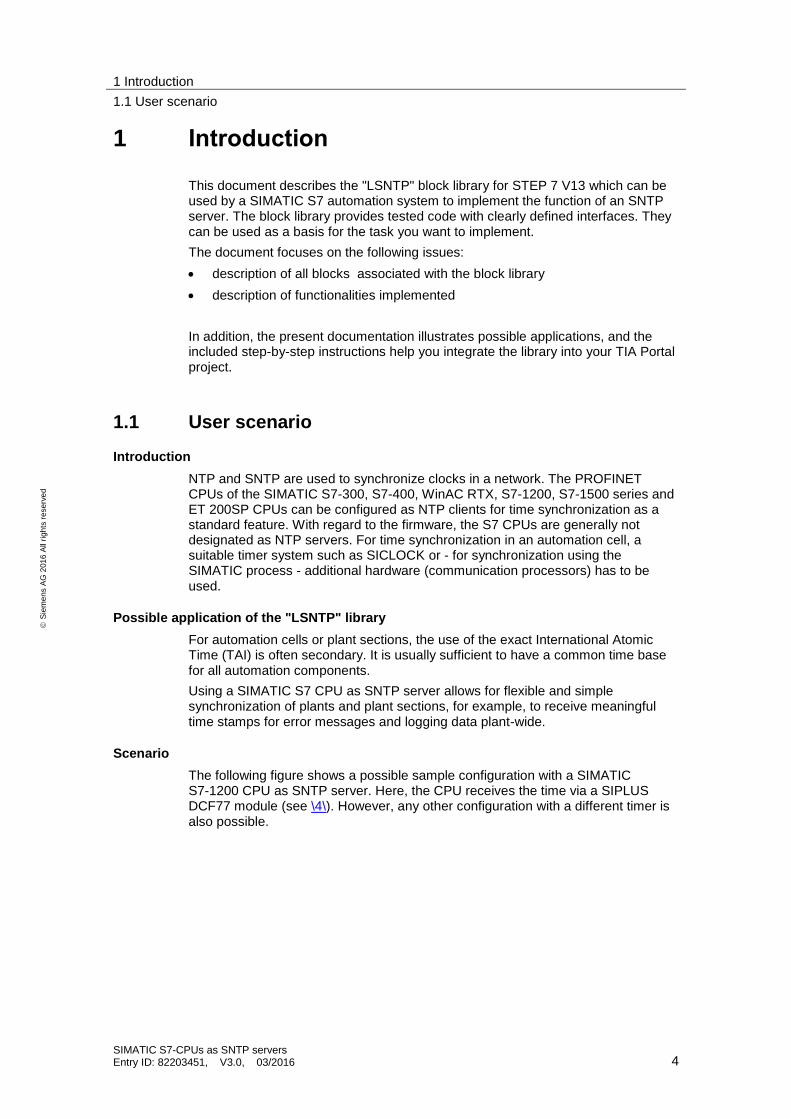
NTP and SNTP are used to synchronize clocks in a network. The PROFINET CPUs of the SIMATIC S7-300, S7-400, WinAC RTX, S7-1200, S7-1500 series and ET 200SP CPUs can be configured as NTP clients for time synchronization as a standard feature. With regard to the firmware, the S7 CPUs are generally not designated as NTP servers. For time synchronization in an automation cell, a suitable timer system such as SICLOCK or - for synchronization using the SIMATIC process - additional hardware (communication processors) has to be used.
Possible application of the "LSNTP" library
For automation cells or plant sections, the use of the exact International Atomic Time (TAI) is often secondary. It is usually sufficient to have a common time base for all automation components.
Using a SIMATIC S7 CPU as SNTP server allows for flexible and simple synchronization of plants and plant sections, for example, to receive meaningful time stamps for error messages and logging data plant-wide.
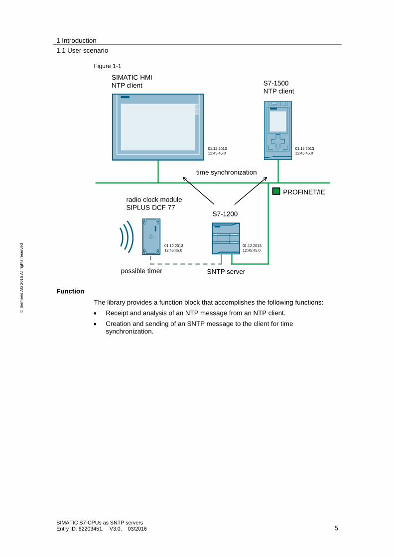
Scenario
The following figure shows a possible sample configuration with a SIMATIC S7-1200 CPU as SNTP server. Here, the CPU receives the time via a SIPLUS DCF77 module (see \4\). However, any other configuration with a different timer is also possible.
1 Introduction
1.1 User scenario
SIMATIC S7-CPUs as SNTP servers Entry ID: 82203451, V3.0, 03/2016 5
S
iem
en
s A
G 2
01
6 A
ll ri
gh
ts r
ese
rve
d
Figure 1-1
PROFINET/IE
SIMATIC HMI
NTP client S7-1500
NTP client
S7-1200
radio clock module
SIPLUS DCF 77
SNTP serverpossible timer
time synchronization
01.12.2013
12:45:45.0
01.12.2013
12:45:45.0
01.12.2013
12:45:45.0
01.12.2013
12:45:45.0
Function
The library provides a function block that accomplishes the following functions:
Receipt and analysis of an NTP message from an NTP client.
Creation and sending of an SNTP message to the client for time synchronization.
1 Introduction
1.2 Hardware and software requirements
SIMATIC S7-CPUs as SNTP servers Entry ID: 82203451, V3.0, 03/2016 6
S
iem
en
s A
G 2
01
6 A
ll ri
gh
ts r
ese
rve
d
1.2 Hardware and software requirements
Requirements for this library
To make use of the full functionality of the library described here, the hardware and software requirements listed below must be met:
Hardware
The "LSNTP" library can be used with all PROFINET S7 CPUs with which Open User Communication (OUC) can be programmed.
These can be CPUs of the following series:
S7-300
S7-400
S7-1200 (CPUs FW ≤ 3.0 or FW ≥ 4.1.3)
S7-1500
ET 200SP
WinAC RTX
Software
The library is available for STEP 7 V13 and higher.
An older version of this library is also available for STEP 7 V5.5 (see \2\).
2 Basics
2.1 System time (UTC) and local time
SIMATIC S7-CPUs as SNTP servers Entry ID: 82203451, V3.0, 03/2016 7
S
iem
en
s A
G 2
01
6 A
ll ri
gh
ts r
ese
rve
d
2 Basics
2.1 System time (UTC) and local time
Explanation of terms
Based on the Universal Time Coordinated (UTC), the local time is determined starting from the prime meridian, taking into account the time shift and summer/winter times, if applicable.
The Central European Time (CET) is calculated as UTC plus one hour. In the summer, the Central European Summer Time (CEST) applies, which is calculated as UTC plus two hours.
The NTP and SNTP always send the UTC according to specification. If the current local time is to be kept, corresponding settings or calculations are required.
S7-1200 and S7-1500
S7-1200 and S7-1500 CPUs include a system time as well as a local time.
When the time of these CPUs is synchronized via an NTP/SNTP server, the UTC is applied as system time and the local time is calculated automatically on the basis of the settings made (also see chapter 5.2).
S7-300 and S7-400
S7-300 and S7-400 CPUs include only a system time which is set to the UTC during synchronization via the CPU using an NTP/SNTP server.
In order to have the local time also available, for example, for the generation of messages, the local time has to be calculated using system-internal functions (see chapter 5.3 or \4\).
2 Basics
2.2 Time synchronization protocol
SIMATIC S7-CPUs as SNTP servers Entry ID: 82203451, V3.0, 03/2016 8
S
iem
en
s A
G 2
01
6 A
ll ri
gh
ts r
ese
rve
d
2.2 Time synchronization protocol
2.2.1 Network Time Protocol (NTP)
Task
NTP serves for the synchronization of clocks in a network. PCs, panels, CPUs, etc. can synchronize time via a (or several) server(s).
Mode of operation
An NTP client sends a message which is already assigned time stamps to the NTP server. The server responds to this message (by using an algorithm, for example, to consider packet runtimes), and the client then sets its clock according to the information received in the message.
An NTP client can have several time servers entered. On the basis of the "stratum" entered in the message and other factors, the client decides in favor of the optimal server and sends the request message to it.
2.2.2 Simple Network Time Protocol (SNTP)
Differentiation between NTP and SNTP
SNTP is a simplified form of the NTP. Due to the simpler algorithms used, the SNTP is less accurate than the NTP. However, for the use in automation cells, the accuracy of the SNTP time synchronization is usually absolutely sufficient.
The structure of the messages is identical in both protocols, which means that NTP clients can also obtain the time from SNTP servers.
2 Basics
2.3 Open User Communication
SIMATIC S7-CPUs as SNTP servers Entry ID: 82203451, V3.0, 03/2016 9
S
iem
en
s A
G 2
01
6 A
ll ri
gh
ts r
ese
rve
d
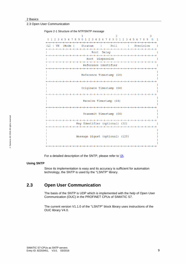
Figure 2-1 Structure of the NTP/SNTP message
For a detailed description of the SNTP, please refer to \3\.
Using SNTP
Since its implementation is easy and its accuracy is sufficient for automation technology, the SNTP is used by the "LSNTP" library.
2.3 Open User Communication
The basis of the SNTP is UDP which is implemented with the help of Open User Communication (OUC) in the PROFINET CPUs of SIMATIC S7.
The current version V1.1.0 of the "LSNTP" block library uses instructions of the OUC library V4.0.
3 Blocks of the library
3.1 Block list
SIMATIC S7-CPUs as SNTP servers Entry ID: 82203451, V3.0, 03/2016 10
S
iem
en
s A
G 2
01
6 A
ll ri
gh
ts r
ese
rve
d
3 Blocks of the library
3.1 Block list
The "LSNTP" library consists of the following blocks and data types.
Table 3-1 Blocks and types of the library for STEP 7 V13
Name Type Version Description
LSNTP_Server FB V2.0.0 Implements the function of the SNTP server.
LSNTP_typeTelegram Data type V1.0.0 Describes the structure of the NTP message.
LSNTP_typeTimestamp Data type V1.0.0 Describes the structure of the time stamp.
3.2 Function principle "LSNTP_Server"
This chapter describes the function principle of the "LSNTP_Server" FB, the calling and formal parameters of the function block for the S7-300/400/WinAC RTX and S7-1200/1500.
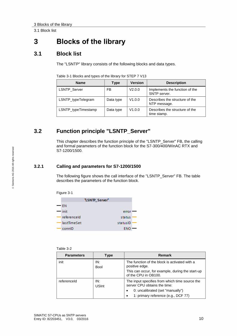
3.2.1 Calling and parameters for S7-1200/1500
The following figure shows the call interface of the "LSNTP_Server" FB. The table describes the parameters of the function block.
Figure 3-1
Table 3-2
Parameters Type Remark
init IN:
Bool
The function of the block is activated with a positive edge.
This can occur, for example, during the start-up of the CPU in OB100.
referenceId IN:
USInt
The input specifies from which time source the server CPU obtains the time:
0: uncalibrated (set "manually")
1: primary reference (e.g., DCF 77)
3 Blocks of the library
3.2 Function principle "LSNTP_Server"
SIMATIC S7-CPUs as SNTP servers Entry ID: 82203451, V3.0, 03/2016 11
S
iem
en
s A
G 2
01
6 A
ll ri
gh
ts r
ese
rve
d
Parameters Type Remark
2: secondary reference (e.g., from GPS receiver)
The information is forwarded to the NTP client in SNTP.
lastTimeSet IN:
DTL
If the information on when the time was set last is available, this information is connected to the input.
The information is forwarded to the NTP client in SNTP.
If the parameter is not assigned, the current time of the CPU is transferred instead.
connID IN:
CONN_OUC
Is assigned with a free connection ID.
The parameter is used internally by the OUC blocks also for connection establishment.
error OUT:
Bool
Shows a configuration error or error of the OUC blocks. Depending on the error type, the output can also be set only for one cycle.
status OUT: Word
Specifies the error (see Chapter 3.2.4).
statusID OUT: Int
Specifies the source of the error (see Chapter 3.2.4).
3 Blocks of the library
3.2 Function principle "LSNTP_Server"
SIMATIC S7-CPUs as SNTP servers Entry ID: 82203451, V3.0, 03/2016 12
S
iem
en
s A
G 2
01
6 A
ll ri
gh
ts r
ese
rve
d
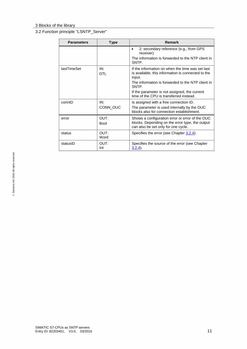
3.2.2 Calling and parameters for S7-300/400
The following figure shows the call interface of the "LSNTP_Server" FB. The table describes the parameters of the function block.
Figure 3-2
Table 3-3
Parameters Type Remark
init IN:
Bool
The function of the block is activated with a positive edge.
This can occur, for example, during the start-up of the CPU in OB100.
referenceId IN:
Int
The input specifies from which time source the server CPU obtains the time:
0: uncalibrated (set "manually")
1: primary reference (e.g., DCF 77)
2: secondary reference (e.g., from GPS receiver)
The information is forwarded to the NTP client in SNTP.
lastTimeSet IN:
Date_and_Time
If the information on when the time was set last is available, this information is connected to the input.
The information is forwarded to the NTP client in SNTP.
If the parameter is not assigned, the current time of the CPU is transferred instead.
connID IN:
Word
Is assigned with a free connection ID.
The parameter is used internally by the OUC blocks also for connection establishment.
localDeviceID IN:
Byte
Specifies the device ID. Further information can be found in the online help of STEP 7 or at \5\.
error OUT:
Bool
Shows a configuration error or error of the OUC blocks. Depending on the error type, the output can also be set only for one cycle.
status OUT: Word
Specifies the error (see Chapter 3.2.4).
statusID OUT: Int
Specifies the source of the error (see Chapter 3.2.4).
3 Blocks of the library
3.2 Function principle "LSNTP_Server"
SIMATIC S7-CPUs as SNTP servers Entry ID: 82203451, V3.0, 03/2016 13
S
iem
en
s A
G 2
01
6 A
ll ri
gh
ts r
ese
rve
d
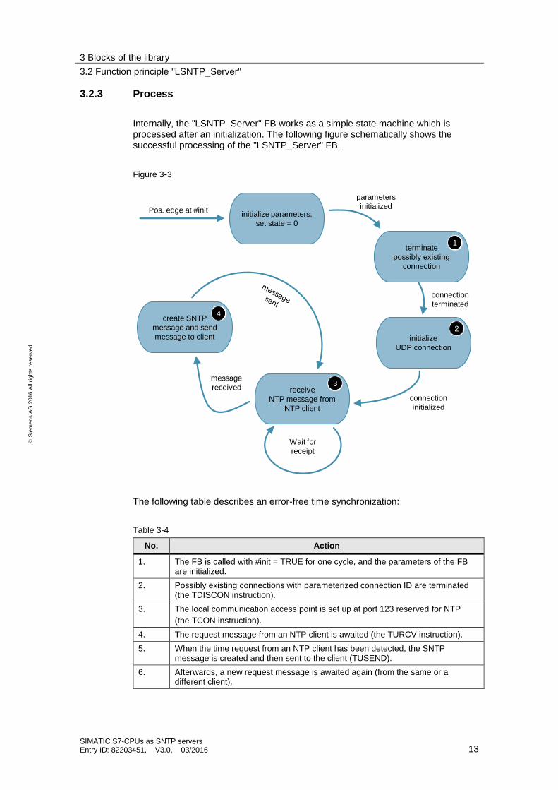
3.2.3 Process
Internally, the "LSNTP_Server" FB works as a simple state machine which is processed after an initialization. The following figure schematically shows the successful processing of the "LSNTP_Server" FB.
Figure 3-3
initialize parameters;
set state = 0
initialize
UDP connection
receive
NTP message from
NTP client
create SNTP
message and send
message to client
connection
initialized
message
received
Wait for
receipt
Pos. edge at #init
parameters
initialized
2
3
4
terminate
possibly existing
connection
connection
terminated
1
The following table describes an error-free time synchronization:
Table 3-4
No. Action
1. The FB is called with #init = TRUE for one cycle, and the parameters of the FB are initialized.
2. Possibly existing connections with parameterized connection ID are terminated (the TDISCON instruction).
3. The local communication access point is set up at port 123 reserved for NTP
(the TCON instruction).
4. The request message from an NTP client is awaited (the TURCV instruction).
5. When the time request from an NTP client has been detected, the SNTP message is created and then sent to the client (TUSEND).
6. Afterwards, a new request message is awaited again (from the same or a different client).
3 Blocks of the library
3.2 Function principle "LSNTP_Server"
SIMATIC S7-CPUs as SNTP servers Entry ID: 82203451, V3.0, 03/2016 14
S
iem
en
s A
G 2
01
6 A
ll ri
gh
ts r
ese
rve
d
Note From any status, it is possible to return to the initialization status with another change of edge at the #init input.
Effect of cycle time
The SNTP message is sent by the server in the same function block and cycle in which the NTP message is received from a client, and the system time is read out. The SNTP message is completely sent within a cycle. As a result, the cycle time has no effect on the accuracy of the transferred time.
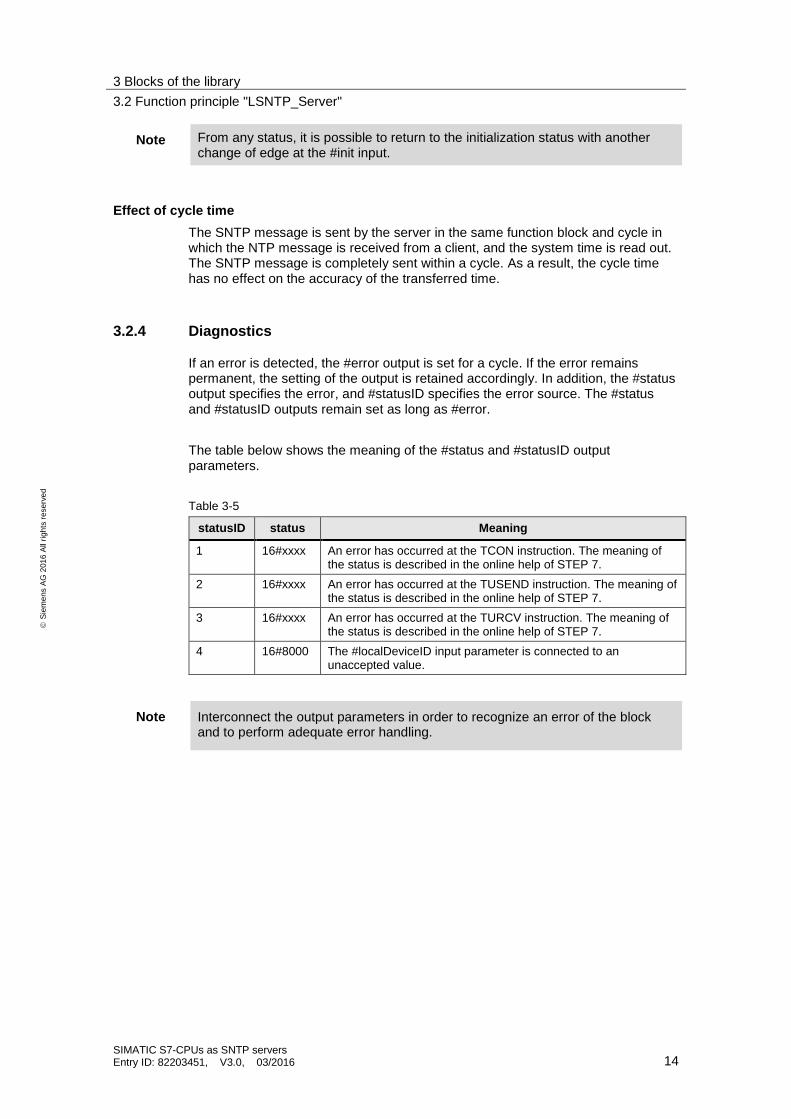
3.2.4 Diagnostics
If an error is detected, the #error output is set for a cycle. If the error remains permanent, the setting of the output is retained accordingly. In addition, the #status output specifies the error, and #statusID specifies the error source. The #status and #statusID outputs remain set as long as #error.
The table below shows the meaning of the #status and #statusID output parameters.
Table 3-5
statusID status Meaning
1 16#xxxx An error has occurred at the TCON instruction. The meaning of the status is described in the online help of STEP 7.
2 16#xxxx An error has occurred at the TUSEND instruction. The meaning of the status is described in the online help of STEP 7.
3 16#xxxx An error has occurred at the TURCV instruction. The meaning of the status is described in the online help of STEP 7.
4 16#8000 The #localDeviceID input parameter is connected to an unaccepted value.
Note Interconnect the output parameters in order to recognize an error of the block and to perform adequate error handling.
4 How to work with the library
4.1 Integrating the library into STEP 7 V13
SIMATIC S7-CPUs as SNTP servers Entry ID: 82203451, V3.0, 03/2016 15
S
iem
en
s A
G 2
01
6 A
ll ri
gh
ts r
ese
rve
d
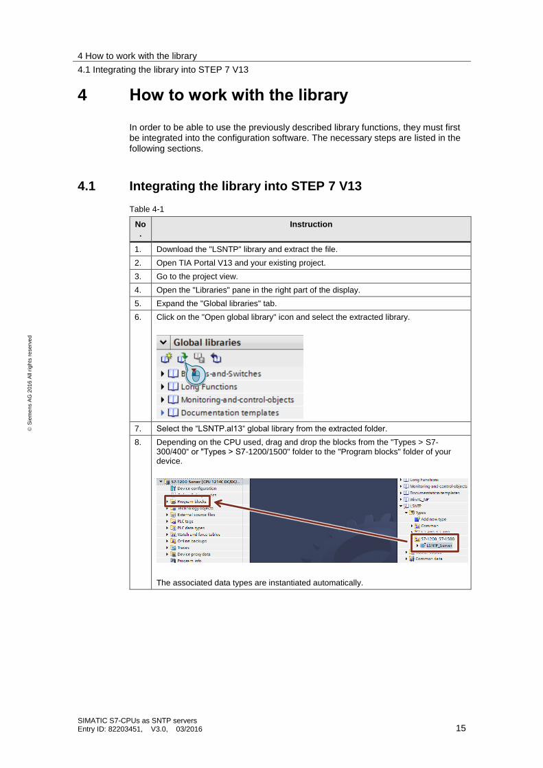
4 How to work with the library
In order to be able to use the previously described library functions, they must first be integrated into the configuration software. The necessary steps are listed in the following sections.
4.1 Integrating the library into STEP 7 V13
Table 4-1
No.
Instruction
1. Download the "LSNTP" library and extract the file.
2. Open TIA Portal V13 and your existing project.
3. Go to the project view.
4. Open the "Libraries" pane in the right part of the display.
5. Expand the "Global libraries" tab.
6. Click on the "Open global library" icon and select the extracted library.
7. Select the “LSNTP.al13“ global library from the extracted folder.
8. Depending on the CPU used, drag and drop the blocks from the "Types > S7-300/400“ or "Types > S7-1200/1500" folder to the "Program blocks" folder of your device.
The associated data types are instantiated automatically.
4 How to work with the library
4.2 Setting up an S7-1200/1500 CPU as SNTP server
SIMATIC S7-CPUs as SNTP servers Entry ID: 82203451, V3.0, 03/2016 16
S
iem
en
s A
G 2
01
6 A
ll ri
gh
ts r
ese
rve
d
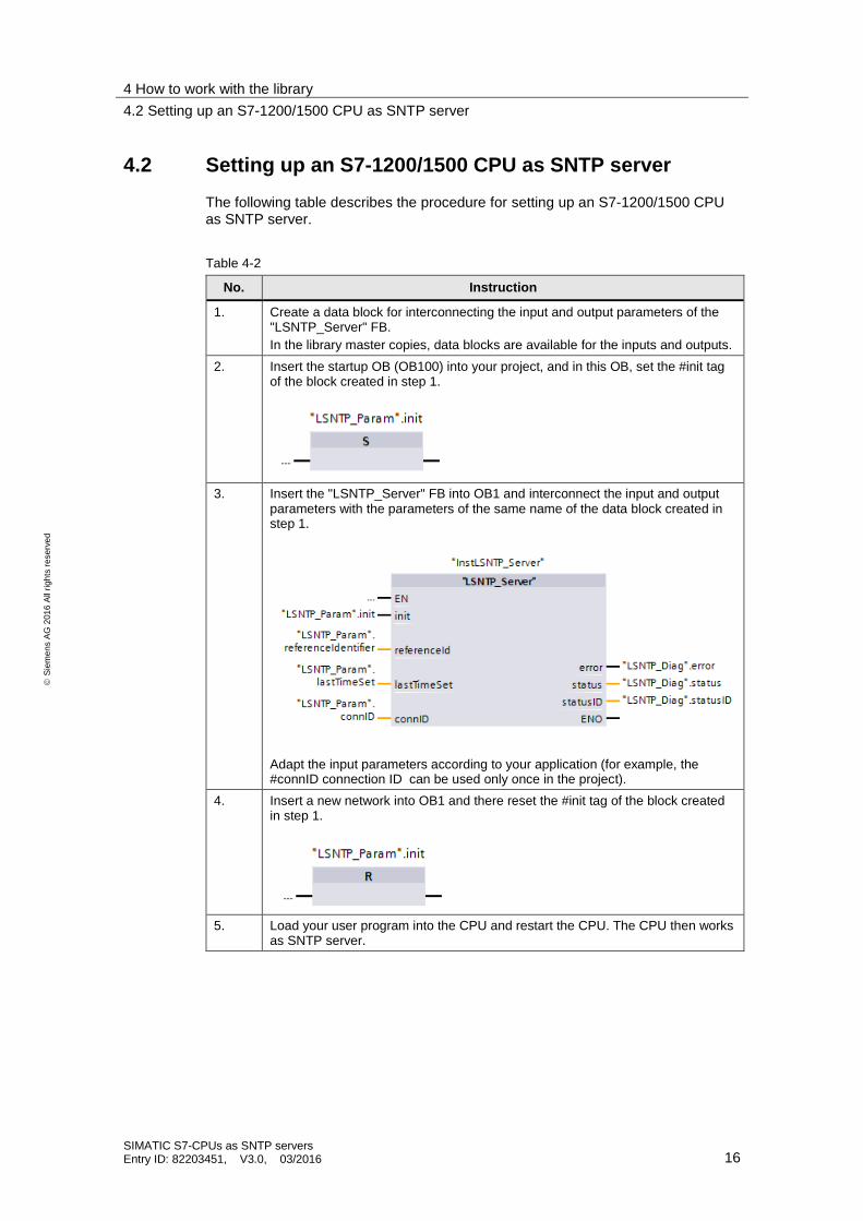
4.2 Setting up an S7-1200/1500 CPU as SNTP server
The following table describes the procedure for setting up an S7-1200/1500 CPU as SNTP server.
Table 4-2
No. Instruction
1. Create a data block for interconnecting the input and output parameters of the "LSNTP_Server" FB.
In the library master copies, data blocks are available for the inputs and outputs.
2. Insert the startup OB (OB100) into your project, and in this OB, set the #init tag of the block created in step 1.
3. Insert the "LSNTP_Server" FB into OB1 and interconnect the input and output parameters with the parameters of the same name of the data block created in step 1.
Adapt the input parameters according to your application (for example, the #connID connection ID can be used only once in the project).
4. Insert a new network into OB1 and there reset the #init tag of the block created in step 1.
5. Load your user program into the CPU and restart the CPU. The CPU then works as SNTP server.
4 How to work with the library
4.3 Setting up an S7-300/400 CPU as SNTP server
SIMATIC S7-CPUs as SNTP servers Entry ID: 82203451, V3.0, 03/2016 17
S
iem
en
s A
G 2
01
6 A
ll ri
gh
ts r
ese
rve
d
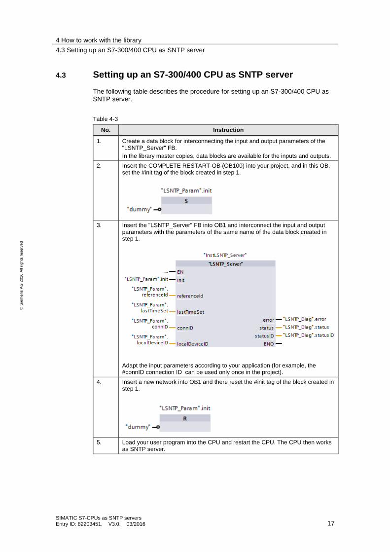
4.3 Setting up an S7-300/400 CPU as SNTP server
The following table describes the procedure for setting up an S7-300/400 CPU as SNTP server.
Table 4-3
No. Instruction
1. Create a data block for interconnecting the input and output parameters of the "LSNTP_Server" FB.
In the library master copies, data blocks are available for the inputs and outputs.
2. Insert the COMPLETE RESTART-OB (OB100) into your project, and in this OB, set the #init tag of the block created in step 1.
3. Insert the "LSNTP_Server" FB into OB1 and interconnect the input and output parameters with the parameters of the same name of the data block created in step 1.
Adapt the input parameters according to your application (for example, the #connID connection ID can be used only once in the project).
4. Insert a new network into OB1 and there reset the #init tag of the block created in step 1.
5. Load your user program into the CPU and restart the CPU. The CPU then works as SNTP server.
5 Notes and support
5.1 Timer
SIMATIC S7-CPUs as SNTP servers Entry ID: 82203451, V3.0, 03/2016 18
S
iem
en
s A
G 2
01
6 A
ll ri
gh
ts r
ese
rve
d
5 Notes and support
5.1 Timer
In order to set the time of the SNTP server, you can use one of the following options:
Setting the CPU clock to the time of the connected PG (with the help of STEP 7). See Table 5-1.
Using the SIPLUS DCF 77 radio clock module.
Reading out the time of a commercially available GPS receiver. For information on that, please refer to \4\.
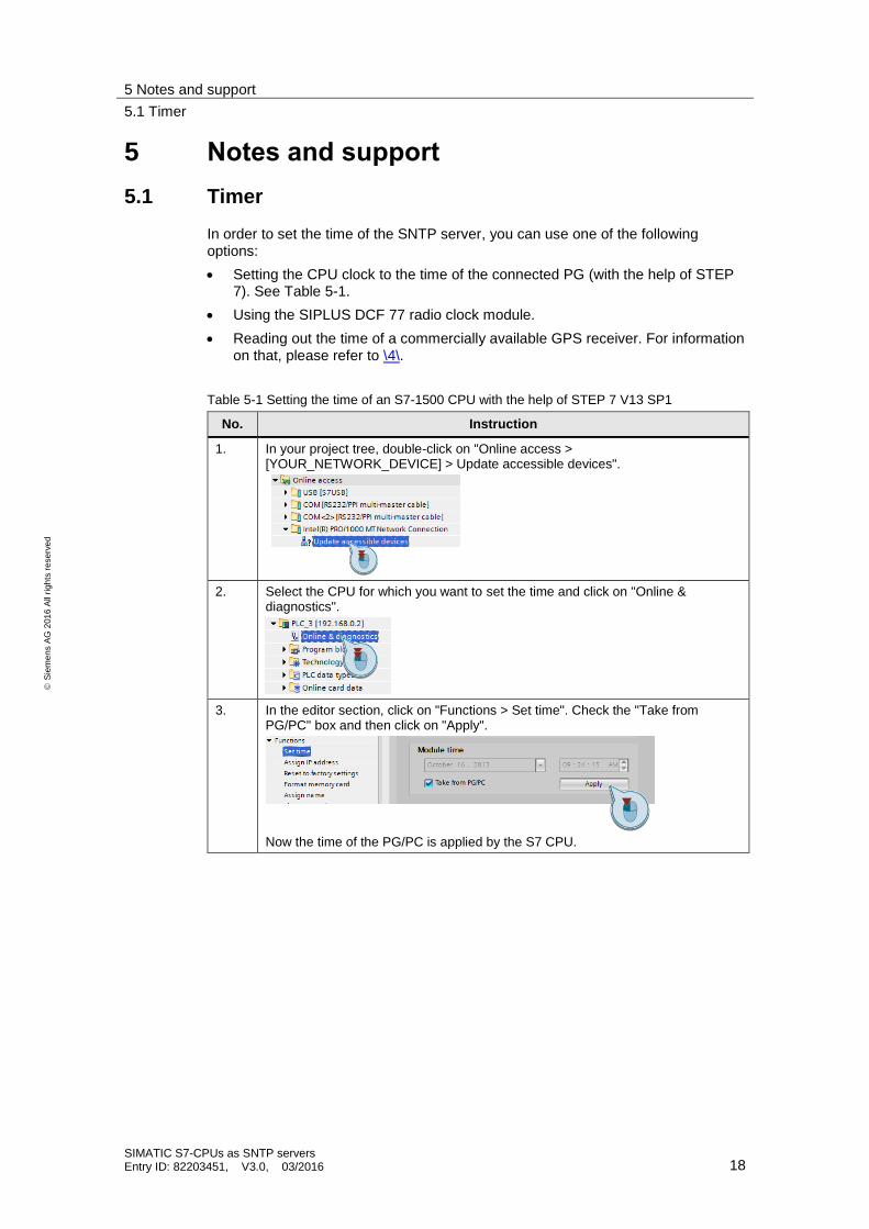
Table 5-1 Setting the time of an S7-1500 CPU with the help of STEP 7 V13 SP1
No. Instruction
1. In your project tree, double-click on "Online access > [YOUR_NETWORK_DEVICE] > Update accessible devices".
2. Select the CPU for which you want to set the time and click on "Online & diagnostics".
3. In the editor section, click on "Functions > Set time". Check the "Take from PG/PC" box and then click on "Apply".
Now the time of the PG/PC is applied by the S7 CPU.
5 Notes and support
5.2 Setting up an S7-1200/S7-1500 as NTP client
SIMATIC S7-CPUs as SNTP servers Entry ID: 82203451, V3.0, 03/2016 19
S
iem
en
s A
G 2
01
6 A
ll ri
gh
ts r
ese
rve
d
5.2 Setting up an S7-1200/S7-1500 as NTP client
Hardware configuration settings
The following table describes how to set up the CPU as NTP client.
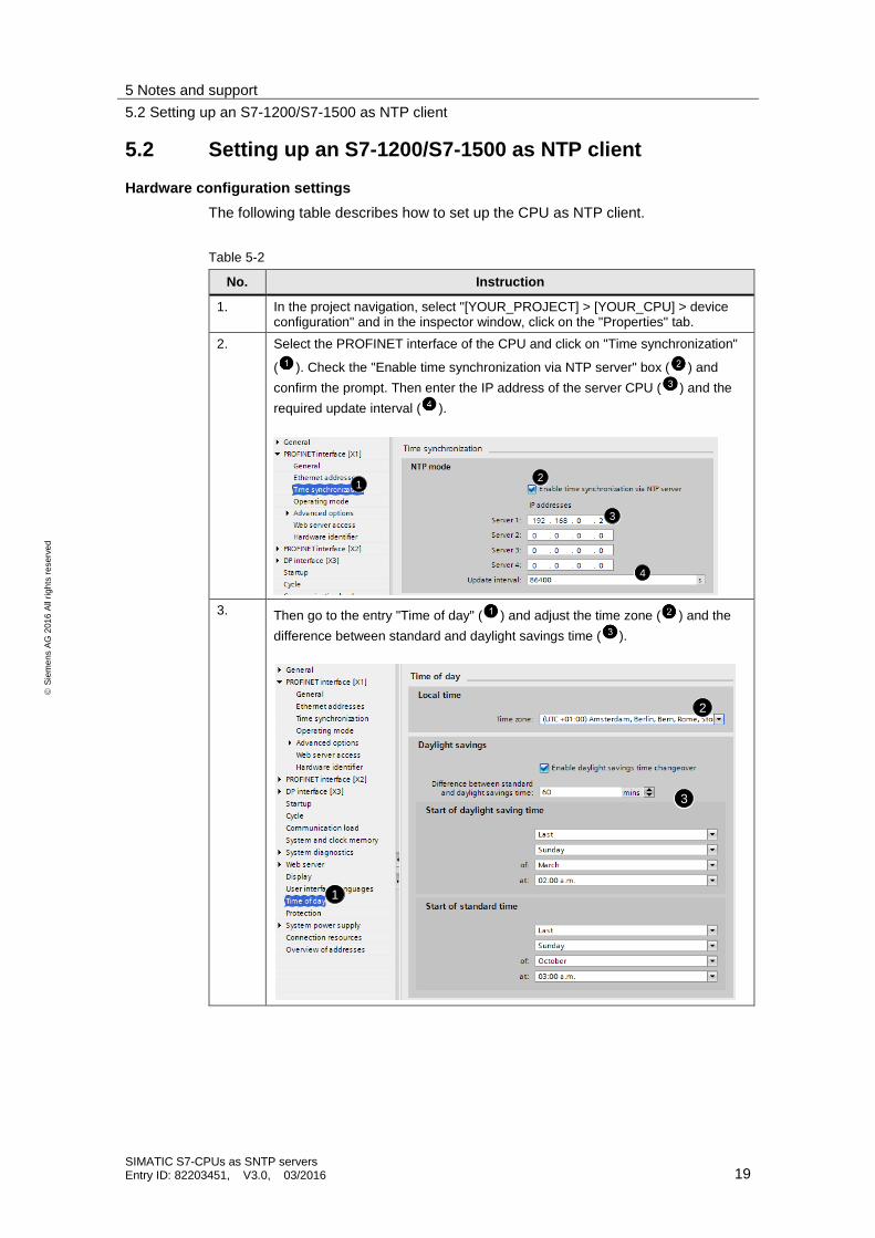
Table 5-2
No. Instruction
1. In the project navigation, select "[YOUR_PROJECT] > [YOUR_CPU] > device configuration" and in the inspector window, click on the "Properties" tab.
2. Select the PROFINET interface of the CPU and click on "Time synchronization"
( ). Check the "Enable time synchronization via NTP server" box ( ) and
confirm the prompt. Then enter the IP address of the server CPU ( ) and the
required update interval ( ).
2
3
4
1
3. Then go to the entry "Time of day" ( ) and adjust the time zone ( ) and the
difference between standard and daylight savings time ( ).
1
2
3
5 Notes and support
5.2 Setting up an S7-1200/S7-1500 as NTP client
SIMATIC S7-CPUs as SNTP servers Entry ID: 82203451, V3.0, 03/2016 20
S
iem
en
s A
G 2
01
6 A
ll ri
gh
ts r
ese
rve
d
Differentiation: system time and local time
The system time of the CPU is the internal time of the CPU, in this case, transferred by the NTP. It is usually provided as UTC.
The local time is the time of the location of the CPU (time zone, summer/winter time) calculated dependent on the system time.
Reading out the system time
The system time can be read out with the "RD_SYS_T" instruction. The "RET_VAL" output parameter of the instruction corresponds to "0" if read-out is completed successfully.
The time is written to a variable via the "OUT" output parameter with one of the following data types:
DT
LDT
DTL
Reading out the local time
The local time of the CPU can be read out with the "RD_LOC_T" instruction. The "RET_VAL" output parameter of the instruction corresponds to "0" if read-out was successful. It corresponds to "1" if read-out was successful, and the local time is currently set to daylight savings time.
The time is written to a variable via the "OUT" output parameter with one of the following data types:
DT
LDT
DTL
5 Notes and support
5.3 Setting up an S7-300/400 as NTP client
SIMATIC S7-CPUs as SNTP servers Entry ID: 82203451, V3.0, 03/2016 21
S
iem
en
s A
G 2
01
6 A
ll ri
gh
ts r
ese
rve
d
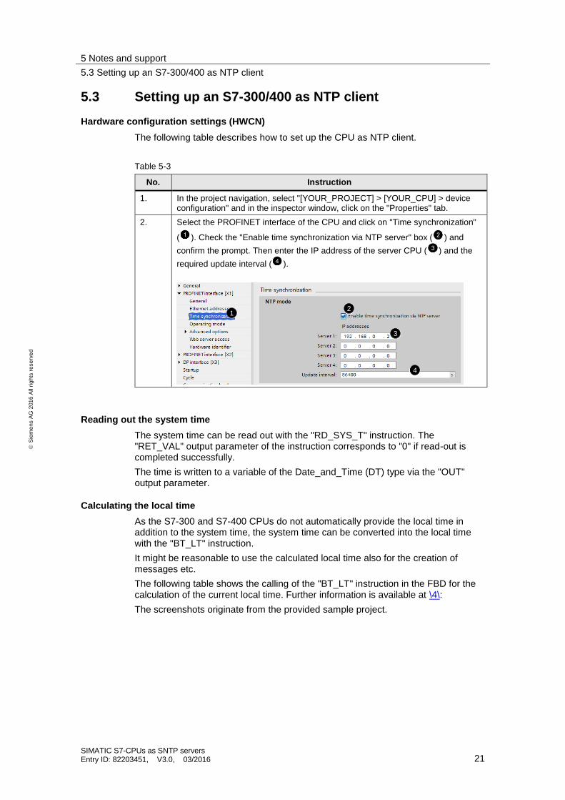
5.3 Setting up an S7-300/400 as NTP client
Hardware configuration settings (HWCN)
The following table describes how to set up the CPU as NTP client.
Table 5-3
No. Instruction
1. In the project navigation, select "[YOUR_PROJECT] > [YOUR_CPU] > device configuration" and in the inspector window, click on the "Properties" tab.
2. Select the PROFINET interface of the CPU and click on "Time synchronization"
( ). Check the "Enable time synchronization via NTP server" box ( ) and
confirm the prompt. Then enter the IP address of the server CPU ( ) and the
required update interval ( ).
2
3
4
1
Reading out the system time
The system time can be read out with the "RD_SYS_T" instruction. The "RET_VAL" output parameter of the instruction corresponds to "0" if read-out is completed successfully.
The time is written to a variable of the Date_and_Time (DT) type via the "OUT" output parameter.
Calculating the local time
As the S7-300 and S7-400 CPUs do not automatically provide the local time in addition to the system time, the system time can be converted into the local time with the "BT_LT" instruction.
It might be reasonable to use the calculated local time also for the creation of messages etc.
The following table shows the calling of the "BT_LT" instruction in the FBD for the calculation of the current local time. Further information is available at \4\:
The screenshots originate from the provided sample project.
5 Notes and support
5.3 Setting up an S7-300/400 as NTP client
SIMATIC S7-CPUs as SNTP servers Entry ID: 82203451, V3.0, 03/2016 22
S
iem
en
s A
G 2
01
6 A
ll ri
gh
ts r
ese
rve
d
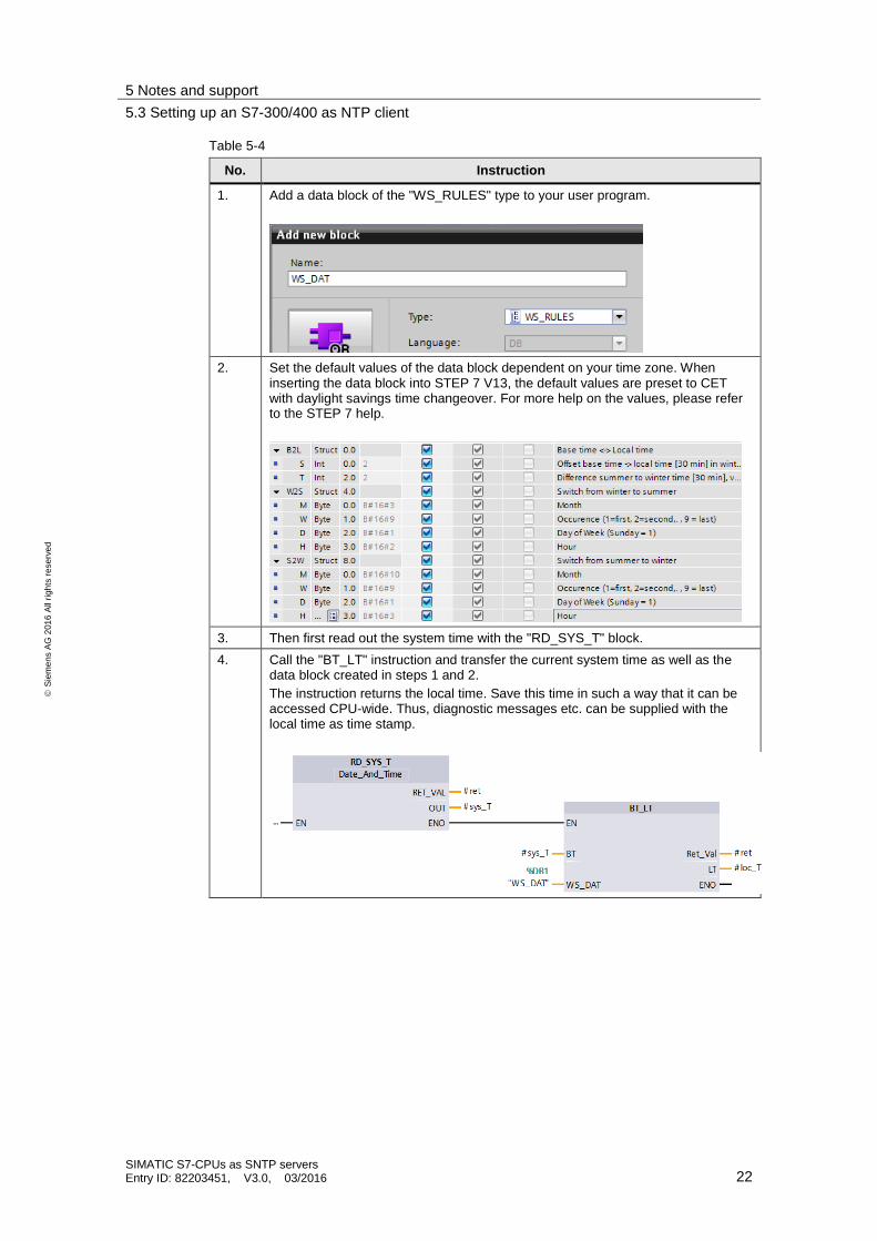
Table 5-4
No. Instruction
1. Add a data block of the "WS_RULES" type to your user program.
2. Set the default values of the data block dependent on your time zone. When inserting the data block into STEP 7 V13, the default values are preset to CET with daylight savings time changeover. For more help on the values, please refer to the STEP 7 help.
3. Then first read out the system time with the "RD_SYS_T" block.
4. Call the "BT_LT" instruction and transfer the current system time as well as the data block created in steps 1 and 2.
The instruction returns the local time. Save this time in such a way that it can be accessed CPU-wide. Thus, diagnostic messages etc. can be supplied with the local time as time stamp.
5 Notes and support
5.4 Setting up Windows PCs as NTP clients
SIMATIC S7-CPUs as SNTP servers Entry ID: 82203451, V3.0, 03/2016 23
S
iem
en
s A
G 2
01
6 A
ll ri
gh
ts r
ese
rve
d
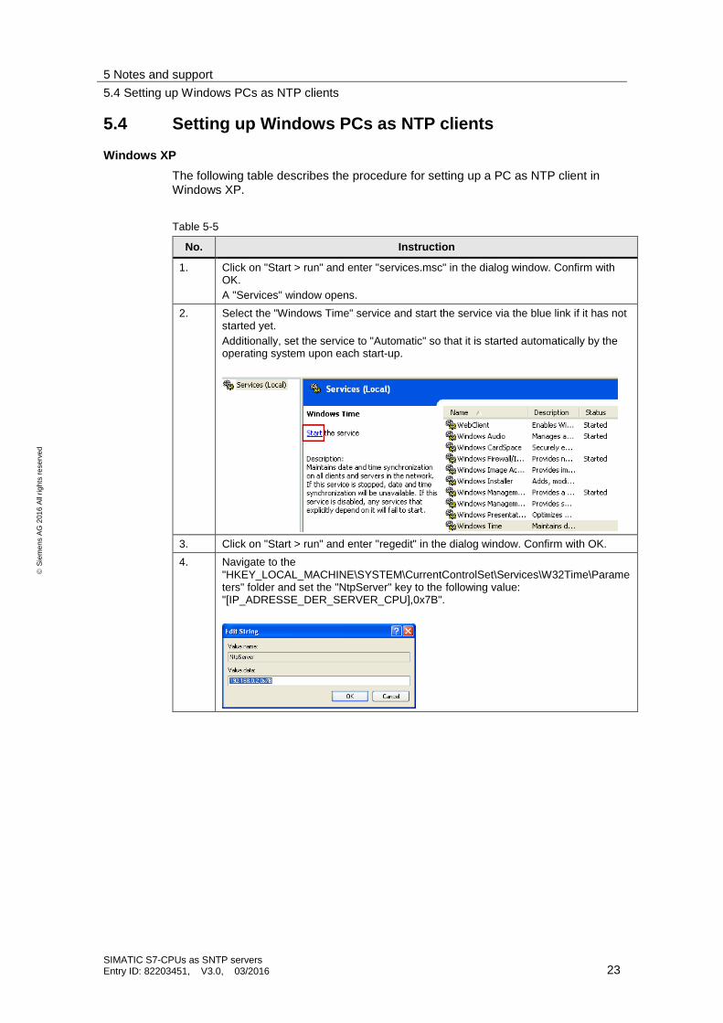
5.4 Setting up Windows PCs as NTP clients
Windows XP
The following table describes the procedure for setting up a PC as NTP client in Windows XP.
Table 5-5
No. Instruction
1. Click on "Start > run" and enter "services.msc" in the dialog window. Confirm with OK.
A "Services" window opens.
2. Select the "Windows Time" service and start the service via the blue link if it has not started yet.
Additionally, set the service to "Automatic" so that it is started automatically by the operating system upon each start-up.
3. Click on "Start > run" and enter "regedit" in the dialog window. Confirm with OK.
4. Navigate to the "HKEY_LOCAL_MACHINE\SYSTEM\CurrentControlSet\Services\W32Time\Parameters" folder and set the "NtpServer" key to the following value: "[IP_ADRESSE_DER_SERVER_CPU],0x7B".
5 Notes and support
5.4 Setting up Windows PCs as NTP clients
SIMATIC S7-CPUs as SNTP servers Entry ID: 82203451, V3.0, 03/2016 24
S
iem
en
s A
G 2
01
6 A
ll ri
gh
ts r
ese
rve
d
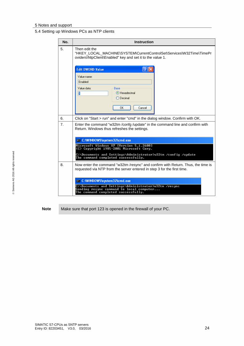
No. Instruction
5. Then edit the "HKEY_LOCAL_MACHINE\SYSTEM\CurrentControlSet\Services\W32Time\TimeProviders\NtpClient\Enabled" key and set it to the value 1.
6. Click on "Start > run" and enter "cmd" in the dialog window. Confirm with OK.
7. Enter the command "w32tm /confg /update" in the command line and confirm with Return. Windows thus refreshes the settings.
8. Now enter the command "w32tm /resync" and confirm with Return. Thus, the time is requested via NTP from the server entered in step 3 for the first time.
Note Make sure that port 123 is opened in the firewall of your PC.
5 Notes and support
5.4 Setting up Windows PCs as NTP clients
SIMATIC S7-CPUs as SNTP servers Entry ID: 82203451, V3.0, 03/2016 25
S
iem
en
s A
G 2
01
6 A
ll ri
gh
ts r
ese
rve
d
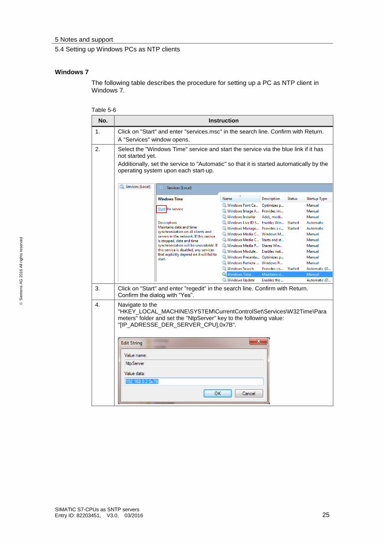
Windows 7
The following table describes the procedure for setting up a PC as NTP client in Windows 7.
Table 5-6
No. Instruction
1. Click on "Start" and enter "services.msc" in the search line. Confirm with Return.
A "Services" window opens.
2. Select the "Windows Time" service and start the service via the blue link if it has not started yet.
Additionally, set the service to "Automatic" so that it is started automatically by the operating system upon each start-up.
3. Click on "Start" and enter "regedit" in the search line. Confirm with Return. Confirm the dialog with “Yes”.
4. Navigate to the "HKEY_LOCAL_MACHINE\SYSTEM\CurrentControlSet\Services\W32Time\Parameters" folder and set the "NtpServer" key to the following value: "[IP_ADRESSE_DER_SERVER_CPU],0x7B".
5 Notes and support
5.4 Setting up Windows PCs as NTP clients
SIMATIC S7-CPUs as SNTP servers Entry ID: 82203451, V3.0, 03/2016 26
S
iem
en
s A
G 2
01
6 A
ll ri
gh
ts r
ese
rve
d
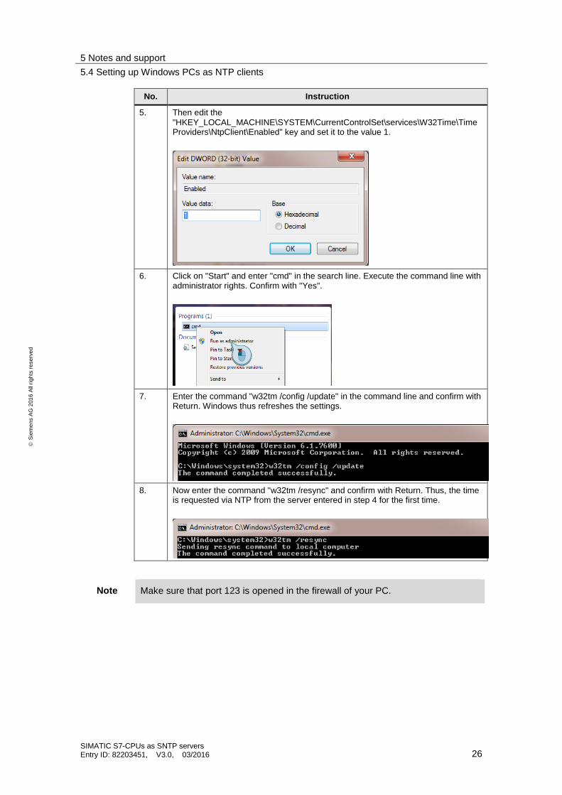
No. Instruction
5. Then edit the "HKEY_LOCAL_MACHINE\SYSTEM\CurrentControlSet\services\W32Time\TimeProviders\NtpClient\Enabled" key and set it to the value 1.
6. Click on "Start" and enter "cmd" in the search line. Execute the command line with administrator rights. Confirm with "Yes".
7. Enter the command "w32tm /config /update" in the command line and confirm with Return. Windows thus refreshes the settings.
8. Now enter the command "w32tm /resync" and confirm with Return. Thus, the time is requested via NTP from the server entered in step 4 for the first time.
Note Make sure that port 123 is opened in the firewall of your PC.
5 Notes and support
5.5 Setting up HMI panels as NTP clients
SIMATIC S7-CPUs as SNTP servers Entry ID: 82203451, V3.0, 03/2016 27
S
iem
en
s A
G 2
01
6 A
ll ri
gh
ts r
ese
rve
d
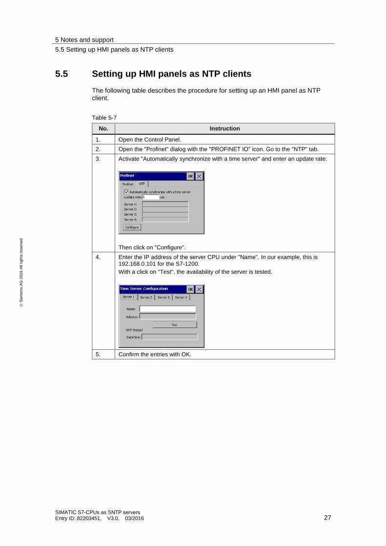
5.5 Setting up HMI panels as NTP clients
The following table describes the procedure for setting up an HMI panel as NTP client.
Table 5-7
No. Instruction
1. Open the Control Panel.
2. Open the "Profinet" dialog with the "PROFINET IO" icon. Go to the "NTP" tab.
3. Activate "Automatically synchronize with a time server" and enter an update rate.
Then click on "Configure".
4. Enter the IP address of the server CPU under "Name". In our example, this is 192.168.0.101 for the S7-1200.
With a click on "Test", the availability of the server is tested.
5. Confirm the entries with OK.
6 References
SIMATIC S7-CPUs as SNTP servers Entry ID: 82203451, V3.0, 03/2016 28
S
iem
en
s A
G 2
01
6 A
ll ri
gh
ts r
ese
rve
d
6 References
Table 6-1
Topic
\1\ Siemens Industry Online Support
https://support.industry.siemens.com
\2\ Download page of the entry https://support.industry.siemens.com/cs/ww/en/view/82203451
\3\ Description of the SNTP, version 3
http://tools.ietf.org/html/rfc4330
\4\ Time synchronization - Time synchronization in the automation environment
https://support.industry.siemens.com/cs/de/de/view/86535497
\5\ FAQ: Which "local_device_id" do you parameterize in order to establish a connection to FB65 "TCON" for open communication via Industrial Ethernet?
https://support.industry.siemens.com/cs/ww/de/view/51339682
7 History
Table 7-1
Version Date Modifications
V1.0 11/2013 First version
V2.0 05/2015 Validity of the V13 library for the S7-1200 CPUs has been adjusted
V3.0 02/2016 Migration to STEP 7 V13 SP1
Updating the OUC library to V4.0
Documentation of the library for STEP 7 V13 as separate document.
Related Documents