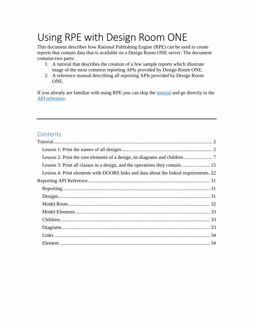
Using RPE with Design Room ONE This document describes how Rational Publishing Engine (RPE) can be used to create reports that contain data that is available on a Design Room ONE server. The document contains two parts: 1. A tutorial that describes the creation of a few sample reports which illustrate usage of the most common reporting APIs provided by Design Room ONE. 2. A reference manual describing all reporting APIs provided by Design Room ONE. If you already are familiar with using RPE you can skip the tutorial and go directly to the API reference. Contents Tutorial ................................................................................................................................ 2 Lesson 1: Print the names of all designs ......................................................................... 2 Lesson 2: Print the root elements of a design, its diagrams and children ....................... 7 Lesson 3: Print all classes in a design, and the operations they contain ....................... 15 Lesson 4: Print elements with DOORS links and data about the linked requirements. 22 Reporting API Reference .................................................................................................. 31 Reporting....................................................................................................................... 31 Designs .......................................................................................................................... 31 Model Roots .................................................................................................................. 32 Model Elements ............................................................................................................ 33 Children......................................................................................................................... 33 Diagrams ....................................................................................................................... 33 Links ............................................................................................................................. 34 Element ......................................................................................................................... 34

Welcome message from author
This document is posted to help you gain knowledge. Please leave a comment to let me know what you think about it! Share it to your friends and learn new things together.
Transcript
Using RPE with Design Room ONE This document describes how Rational Publishing Engine (RPE) can be used to create
reports that contain data that is available on a Design Room ONE server. The document
contains two parts:
1. A tutorial that describes the creation of a few sample reports which illustrate
usage of the most common reporting APIs provided by Design Room ONE.
2. A reference manual describing all reporting APIs provided by Design Room
ONE.
If you already are familiar with using RPE you can skip the tutorial and go directly to the
API reference.
Contents Tutorial ................................................................................................................................ 2
Lesson 1: Print the names of all designs ......................................................................... 2
Lesson 2: Print the root elements of a design, its diagrams and children ....................... 7
Lesson 3: Print all classes in a design, and the operations they contain ....................... 15
Lesson 4: Print elements with DOORS links and data about the linked requirements. 22
Reporting API Reference .................................................................................................. 31
Reporting....................................................................................................................... 31
Designs .......................................................................................................................... 31
Model Roots .................................................................................................................. 32
Model Elements ............................................................................................................ 33
Children......................................................................................................................... 33
Diagrams ....................................................................................................................... 33
Links ............................................................................................................................. 34
Element ......................................................................................................................... 34
Tutorial This tutorial assumes you have RPE Document Studio 2.1.1 installed. Using a different
version of RPE will most likely also work, but you may notice small differences
compared to the described steps and screen shots.
Although you can test the sample reports on your own models, you may want to use the
model “JKE Banking” which you find next to this document ((in <dr-server-install-
folder>\DR_ReleaseManagement\doc\reporting_with_rpe\JKE Banking)). The tutorial
assumes you have exported this model to a Design Room ONE server and called the
design “DemoRPE”.
The first lesson assumes no previous experience from using RPE and is therefore rather
detailed. Subsequent lessons build on the previous ones and will not go into the same
level of detail.
Lesson 1: Print the names of all designs Sample report: DR_all_designs.dta Reporting APIs used: Designs
Let’s start by the simplest possible report – a listing of all designs that are available on a
Design Room ONE server.
1. Create a new document template (New – Document Template). Save it as
“DR_all_designs.dta”.
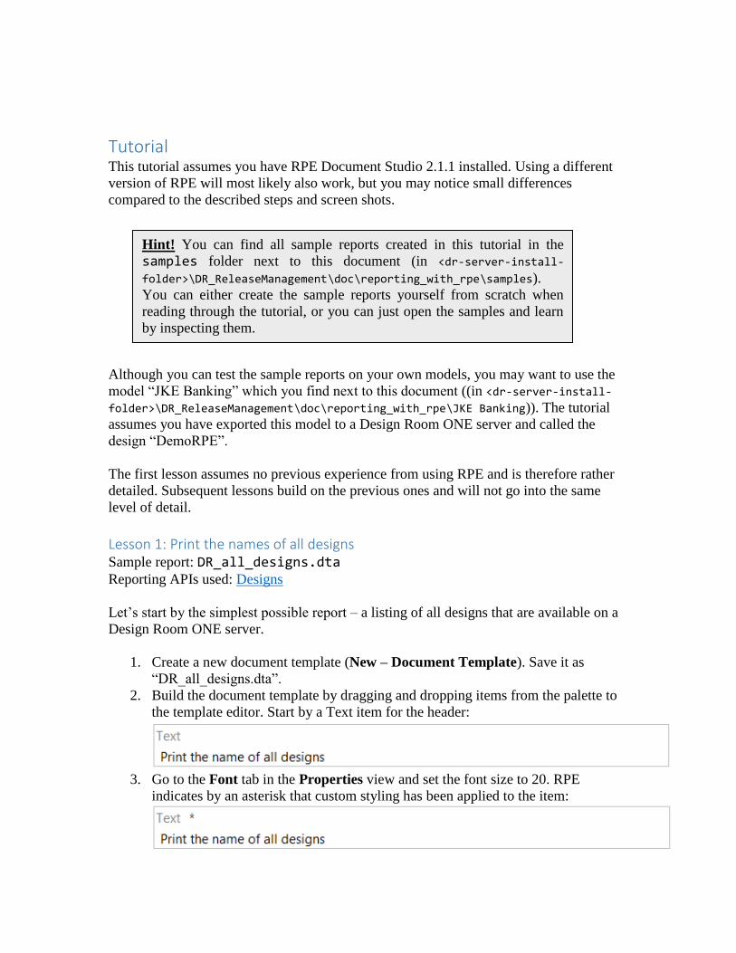
2. Build the document template by dragging and dropping items from the palette to
the template editor. Start by a Text item for the header:
3. Go to the Font tab in the Properties view and set the font size to 20. RPE
indicates by an asterisk that custom styling has been applied to the item:
Hint! You can find all sample reports created in this tutorial in the
samples folder next to this document (in <dr-server-install-
folder>\DR_ReleaseManagement\doc\reporting_with_rpe\samples).
You can either create the sample reports yourself from scratch when
reading through the tutorial, or you can just open the samples and learn
by inspecting them.

4. Place a Container item under the Text item. Container items are used for
extracting the data, that should go into the report, from Design Room ONE (and
possibly also other tools).
5. Next you need to specify from where the container should get its data. In RPE
terminology this is called a data source. A convenient way to specify the data
source is to use a wizard that is provided by RPE. Perform the command Data –
Schema Discovery – REST Schema Discovery. Press Next.
The base reporting URL for Design Room ONE is
https://<server>:<port>/dr/reporting (see Reporting API). From this URL you can
interactively discover all other reporting URLs using the wizard.
Give the name “Designs” to this data source, but leave other fields empty (Design
Room ONE does not require authentication for accessing the reporting APIs).

6. Press Next. You will see the schema of the Reporting API.
Select the Item element and mark all its attributes in the right pane.
7. Press Next. RPE will now invoke the Reporting API and show the result in a
table.
Select the “designs” entry which references the Designs API.
8. Press Finish. A data source will be created for the Designs API. The data source
appears in the Data Source view:

9. Now that we have a data source for getting all designs, we can bind it to the
Container item we created previously. Select the Design element in the Data
Source view, drag it to the document template and drop it on the Container item.
RPE shows that the container is bound to the “Designs” data source. It also shows
that the element Design will be extracted from the data source. There is one such
element for each design and the container will iterate over them all. The variable
($34 in the picture, but another number may be used in your case) is automatically
assigned by RPE to let you refer to the extracted Design element within the
container.
10. Create a Paragraph inside the container, and create two Text items inside the
paragraph. Your document template should now look like this:
11. Double-click on the first Text item and enter the text: “Design: “ as a simple
value. This static text will be printed once for each design. Double-click on the
second Text item and select the design name as its value. You find it in the Data
Expression tab under Attributes:

Alternatively you can drag the “name” attribute from the Data Source view and
drop it onto the Text item.
12. The document template is now ready and should look like this:
13. Now it’s time to test the template by generating a report. Perform the command
Configure and Generate Document from the toolbar.
14. In the wizard that appears you need to enter the URL for all data sources that are
used by the template. Enter the URL for the Designs API:
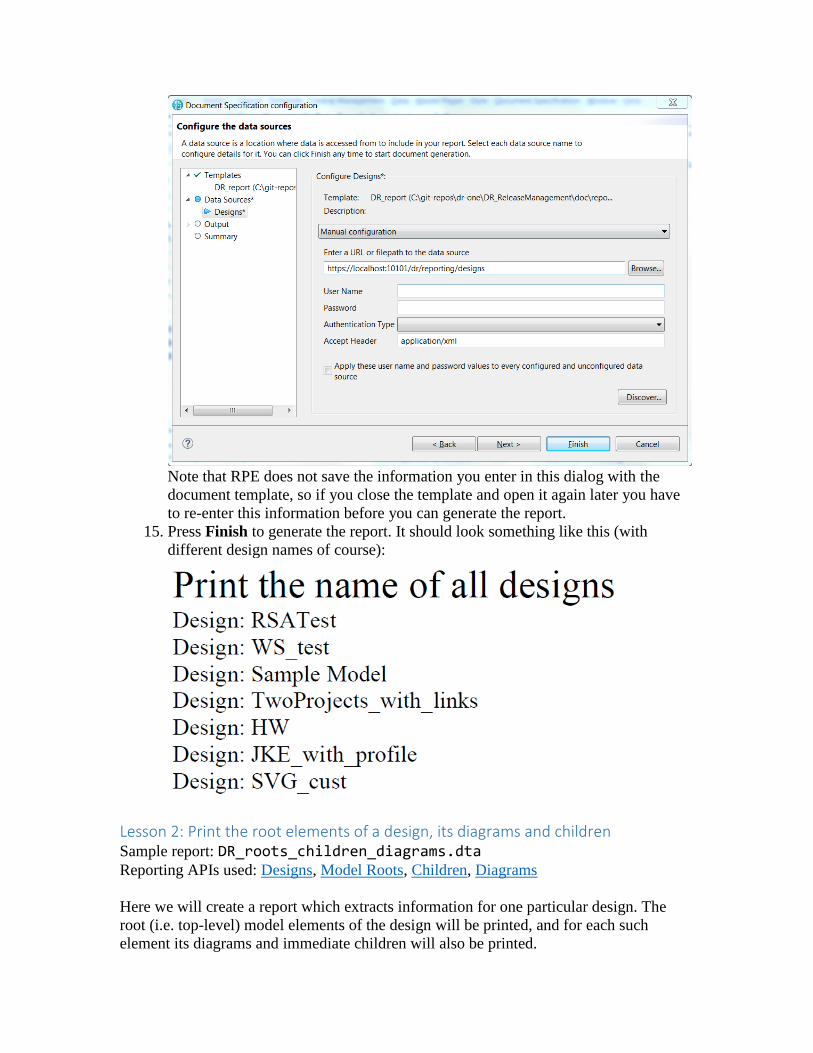
Note that RPE does not save the information you enter in this dialog with the
document template, so if you close the template and open it again later you have
to re-enter this information before you can generate the report.
15. Press Finish to generate the report. It should look something like this (with
different design names of course):
Lesson 2: Print the root elements of a design, its diagrams and children Sample report: DR_roots_children_diagrams.dta Reporting APIs used: Designs, Model Roots, Children, Diagrams
Here we will create a report which extracts information for one particular design. The
root (i.e. top-level) model elements of the design will be printed, and for each such
element its diagrams and immediate children will also be printed.
In lesson 1 you learnt how to use the palette for creating a document template and the
REST Resource Discovery wizard for creating data sources. In this lesson you will learn
about external variables, native filtering, dynamic data source configuration and images.
1. Start by creating this template (either from scratch or by modifying the template
you built in lesson 1):
Refer to lesson 1 if you forgot the steps to create the Designs data source.
If you generate a report for this template you will see that it looks exactly like the
one we built in lesson 1, where the names of all designs are printed.
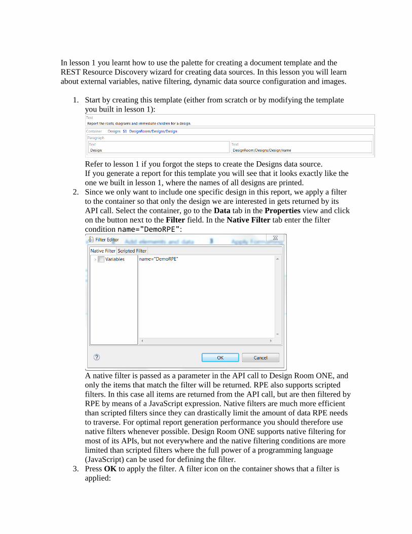
2. Since we only want to include one specific design in this report, we apply a filter
to the container so that only the design we are interested in gets returned by its
API call. Select the container, go to the Data tab in the Properties view and click
on the button next to the Filter field. In the Native Filter tab enter the filter
condition name="DemoRPE":
A native filter is passed as a parameter in the API call to Design Room ONE, and
only the items that match the filter will be returned. RPE also supports scripted
filters. In this case all items are returned from the API call, but are then filtered by
RPE by means of a JavaScript expression. Native filters are much more efficient
than scripted filters since they can drastically limit the amount of data RPE needs
to traverse. For optimal report generation performance you should therefore use
native filters whenever possible. Design Room ONE supports native filtering for
most of its APIs, but not everywhere and the native filtering conditions are more
limited than scripted filters where the full power of a programming language
(JavaScript) can be used for defining the filter.
3. Press OK to apply the filter. A filter icon on the container shows that a filter is
applied:
If you now run report generation for the template you will see that only the design
called “DemoRPE” will get included in the report.
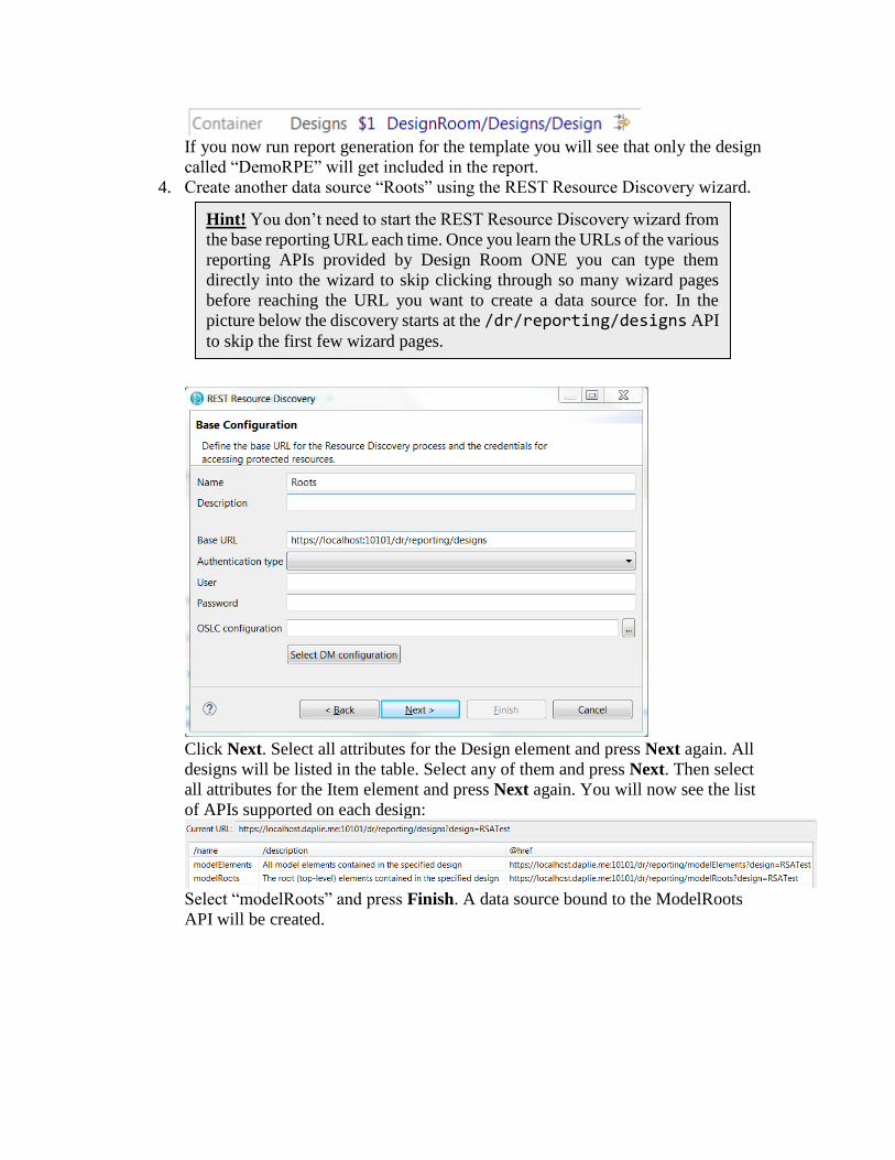
4. Create another data source “Roots” using the REST Resource Discovery wizard.
Click Next. Select all attributes for the Design element and press Next again. All
designs will be listed in the table. Select any of them and press Next. Then select
all attributes for the Item element and press Next again. You will now see the list
of APIs supported on each design:
Select “modelRoots” and press Finish. A data source bound to the ModelRoots
API will be created.
Hint! You don’t need to start the REST Resource Discovery wizard from
the base reporting URL each time. Once you learn the URLs of the various
reporting APIs provided by Design Room ONE you can type them
directly into the wizard to skip clicking through so many wizard pages
before reaching the URL you want to create a data source for. In the
picture below the discovery starts at the /dr/reporting/designs API
to skip the first few wizard pages.

5. Create a Roots container, nested within the Designs container, and create a
Paragraph containing an Image and three Text items:
6. Contrary to the Designs data source, the Roots data source must be dynamic. That
is, rather than configuring it once when generating the report, it must be
configured once for each design (since the design is a parameter in the URL that
is bound to this data source). To configure the Roots data source dynamically,
place a Data Source Configuration item just before the Roots container:
7. Select the Data Source Configuration. Go to the Data tab in the Properties view
and set the Target data source to Roots. This specifies a dynamic data source,
and a new properties tab Dynamic configuration appears (you need to deselect
the Data Source Configuration and select it again). In this tab, the URI field
specifies the URI of the data source. We will use a script expression for setting
this URI. To avoid hard coding the URL of the Design Room ONE server in each
data source configuration URI, we should first define a variable which we can
reference from the URI.
8. Create a variable by right-clicking on the Variables item in the Outline view.
Select Insert – New Variable in the context menu and create a variable
DR_SERVER like this:

The variable is external which means that it should be set when generating the
report. However, by specifying a default value we only need to set it if we want to
use data from a non-default Design Room ONE server.
9. Now we can write the script expression for the URI property of the Data Source
Configuration:
Note that you must mark the variables and attributes, that are referenced by the
script expression, in the left pane. In this case we reference the DR_SERVER

variable and the name and localConfiguration attributes of the Design
element. Note that the localConfiguration attribute is only available if you
have chosen to export the local configuration information with the design. If this
attribute is present we must set the oslc_config.context parameter in the
request for the root elements, to ensure that the correct version of the design will
be used. As a general rule, always set the oslc_config.context parameter
like this in all requests where a design name is included.
10. Enter data for the three Text items. In the first one drag and drop the attribute
metaClass from the Roots data source. During report generation it will expand
to the name of the meta class of the root model element (typically “Package”). In
the second Text item type the simple value “ : “ to be used as separator. In the
third Text item drag and drop the attribute name from the Roots data source
which will expand to the name of the root element. Note that when you drop an
attribute on a Text item you should select “Use as value” in the Select Context
dialog that appears.
11. Set the content URL of the Image to fetch the icon for the root element. Double-
click on the Image and enter the following script expression:
The icon attribute from the ModelElement element contains the path to the icon
of the model element, so we just need to append that to the DR_SERVER variable
to obtain the full URL of the icon.
12. Now is a good time to save and test your template. You should avoid too many
modifications in a template before trying it out, to simplify troubleshooting in
case something does not work as expected. The generated report should look like
this:
Hint! You can drag and drop the variables and attributes from the left
pane into the script expression to avoid typos.

Note that even if the Roots data source is dynamic you need to specify a value for
it when generating the report. You can use any string (but it must be a URL) since
the data source is dynamic. For example, you can use the string
https://dynamic_data_source.
13. To include the diagrams and children elements of the root elements into the report
we need to create two new data sources. Use the REST Schema Discovery wizard
to add these. Start the wizard on the URL
https://localhost:10101/dr/reporting/modelRoots?design=DemoRPE to save some
clicking. On the third wizard page you get the list of root elements (only one for
the DemoRPE design). Select it and proceed to the fourth wizard page which lists
the reporting APIs available for a model element:
Create a data source Children bound to the URL stored in the href attribute of
the Children element, and another data source Diagrams bound to the URL stored
in the href attribute of the Diagrams element:
14. Add a container for each of these two data sources. Place them next to each other
inside the Roots container. Use two Data Source Configuration items to configure
them dynamically using the following scripts:

• Set the URI of the Diagrams data source to: DR_SERVER + '/dr/reporting/diagrams?design=' + name + (localConfiguration ? '&oslc_config.context=' + localConfiguration : '') + '&elementId=' + id
• Set the URI of the Children data source to:
DR_SERVER + '/dr/reporting/children?design=' + name + (localConfiguration ? '&oslc_config.context=' + localConfiguration : '') + '&elementId=' + id
where name and localConfiguration is the name and local configuration
of the design, and id is the id of the root element.
15. In the Diagrams container add a Text item to show the name of the diagram
(attribute name of the Diagrams data source) and an Image item to show the
diagram image (attribute url of the Diagrams data source):
16. In the Children container add an Image and three Text items in the same way as
you did for the root element. In the script expression for the Image URL make
sure you reference the icon of the child element and not the icon of the root
element.

17. The document template is now ready. It should look like this:
The generated report should now contain the diagrams for the root elements, as
well as icon, meta class and name for all its immediate children.
Lesson 3: Print all classes in a design, and the operations they contain Sample report: DR_classes_operations.dta Reporting APIs used: Model Elements, Children, Element
Here we will create a report which extracts information for one particular design. In the
previous lesson we used native filtering on the Designs API to find the design to generate
the report for. In this lesson we will instead specify the design using an external variable.
We will use the Model Elements API with native filtering to find all classes in the design.
We will sort the classes alphabetically and print some information about each of them,
such as the operations they contain. You will learn how to use the Element API to extract
information about a particular model element. You will also learn how to use internal
variables, hyperlinks, sorting and scripted filters.
1. Start by creating two external variables: DESIGN (to hold the name of the design
to report on) and DR_SERVER (same as in previous lesson).
2. Create the data sources we need for this lesson. Use the REST Resource
Discovery wizard and start on the URL
https://localhost:10101/dr/reporting/designs?design=DemoRPE. Create a
ModelElements data source for the ‘modelElements’ entry on the second wizard
page.

Then restart the wizard and click further until you reach the ModelElement
schema where you can create a data source Children. On this same wizard page
you also see an Owner element for which you can create a data source Element.
Note that when the wizard lists all model elements in the design (before you reach
the page shown above) you must select an element that has both an owner and
some children. For example, do not select a root element as in that case no owner
will be present, and the wizard will not let you create a data source for the
Element API.

3. Create the template shown below:
Configure the data source configuration using the script expression
DR_SERVER + '/dr/reporting/modelElements?design=' + DESIGN
Here we have assumed that the design specified by the DESIGN variable has been
exported without any local configuration information. To support also designs
with local configurations we would have to add the setting of the
oslc_config.context parameter as described in the previous lesson.
Finally also set a native filter for the container like this
metaClass=Class
4. If we would generate a report now (try it if you like) we would get a listing of all
classes in the design. The classes will appear in a seemingly random order. We
can make the list sorted by selecting the container, and in the Data tab of the
Properties view click on the button next to the Sort field. Just as for filtering,
sorting can either be native (performed by Design Room ONE) or scripted
(performed by RPE). Currently Design Room ONE does not support native
sorting so you have to use the somewhat slower scripted alternative. Add the
name attribute to the right table to sort the classes by their names.
Hint! A quick way to start the REST Resource Discovery wizard directly
on the page that shows the schema for the Element API is to locate an
element in the Design Room ONE web application. Select it in the
Explorer view and open the Advanced tab in the Properties view. There
you will find the reporting URL for the element. You can copy the URL
and paste it into the REST Resource Discovery wizard:

RPE shows an icon on the container to indicate that the elements will be sorted:
5. Now run report generation for the template. You need to enter a value for the
DESIGN variable (in the Document Specification Configuration dialog) since we
did not give it a default value. Set it for example to “DemoRPE”. You also need
to specify URLs for the three data sources we have. Since all these data sources
are dynamic (i.e. will be configured dynamically while the report generation runs)
you can enter any URL for them. For example, you can use
https://dynamic_data_source to show that the data sources are dynamic.
The generated report should look like this:
6. Next let’s extract the owner element for each of the classes and add a hyperlink to
it in the report. We use the Element data source for getting this data. Add this
inside the container:
Configure the data source using the script expression
DR_SERVER + '/dr/reporting/element?design=' + DESIGN + '&elementId=' + id
where id refers to the id of the current model element. Once again we have
omitted setting the oslc_config.context parameter, but to support designs
with local configurations you would have to set it.

The nested container extracts the owner of the model element. Previously we have
only used containers for extracting a list of items, to let the container iterate over
them, but containers can also be used to extract a single item like the owner
element.
7. The Owner element extracted by the Element container has an href attribute
which contains the URL of the owner element. To extract information about the
owner element, such as its name, we need to query that URL. However, the URL
we get is the Element API which is also used by the parent container. You must
be careful when reconfiguring a data source whose elements you are currently
iterating over. Changing the URL of the data source inside the container typically
affects the iteration, which often is undesired. To solve this problem, we create an
internal variable OWNER_HREF and assign the value of the href attribute to it
in the Element container. You do the assignment by selecting the container and
then in the General tab in the Properties view click on the button next to the
Assignment field. Click the Add button in the dialog and select the
OWNER_HREF variable in the list that appears. Set the value of the variable to
the href attribute of the Owner element.
The assignment should look like this:
8. Now we can reconfigure the Element data source after the container that extracts
the owner element to avoid unwanted side effects. Note that another benefit with
this is that the template gets fewer levels of container nesting.
Add the following items after the container with the variable assignment:
Configure the Element data source using a data expression that references the
OWNER_HREF variable:

9. Set-up the hyperlink using the Properties view. In the Content tab click the
button in the bottom right corner and enter this script expression
DR_SERVER + '/dr/web?design=' + DESIGN + '&id=' + id + '&type=model'
where id references the id of the owner element ($7 in the picture above). The
constructed URL opens the Design Room ONE web application and navigates to
the owner element. To support designs with local configurations we would also
need to set the oslc_config.context parameter as mentioned previously.
Then go to the Specific tab and click the button next to the Display field. Enter a
data expression that references the name of the model element:
To make the hyperlink look like a hyperlink we also need to apply some
formatting. In the Font tab set blue font color and click the underline button.
10. Now run report generation again. You should see a hyperlink after each class that
links to the owner of the class.
If you click on the link, Design Room ONE will open the design and navigate to
the owner element.
11. Now let’s add the operations of each class. Operations are child elements of their
class, so we use the Children data source for getting them. Add the below items at
the end of the outermost container:

Configure the Children data source using the following script expression:
DR_SERVER + '/dr/reporting/children?design=' + DESIGN + '&elementId=' + id
To support designs with local configurations we would also need to set the
oslc_config.context parameter as mentioned previously.
Set-up the content of the Image using this script expression:
DR_SERVER + icon
where icon references the icon attribute of the child element.
To only get the operations, and not all other children, set up a native filter on the
Children container like this:
metaClass=Operation Finally apply a little formatting to make the report look nicer. Let the first Text
item have bold font and its container Paragraph a border:
12. In the DemoRPE design few of the classes have any operations. However, there
are several components in that design which contain operations. Therefore let’s
modify the filter of the outermost container so that it fetches both classes and
components. This is an example of filtering that currently cannot be accomplished
by means of a native filter, so we need to use a script filter instead:

13. Our template is now ready. The completed template looks like this:
Generate a report. It should look like this:
Lesson 4: Print elements with DOORS links and data about the linked requirements Sample report: DR_links_requirements.dta Reporting APIs used: Model Elements, Element, Links
Here we will create a report which extracts all elements in a particular design for which
there is at least one outgoing link to a requirement in DOORS NG. The links are printed
in a table below the element.

In this lesson you will learn about the Links API, tables, conditions and how to create a
report that contains data from multiple tools (in this case Design Room ONE and
DOORS NG).
1. Start by creating data sources for the ModelElements and Element APIs as in the
previous lesson. Also create the external variables DR_SERVER and DESIGN in
the same way as before. Then create the following template:
The ModelElements data source is configured using the following script
expression:
DR_SERVER + '/dr/reporting/modelElements?design=' + DESIGN Note that in this case we don’t apply a filter on the container since we want to
iterate over all model elements in the design. This is because it is possible to link
any model element to a requirement.
Also note that for simplicity we have assumed that the design specified by the
DESIGN variable does not have any local configurations. If it does, you would
need to also set the oslc_config.context parameter as described in previous
lessons.
2. Just as we did in the previous lesson we use the Element data source and an
internal variable for extracting the href attribute of the Links element that is
contained in the ModelElement element. Let’s call this variable LINKS_HREF
and add a container where it is assigned.
The Element data source should be configured using this script expression:
DR_SERVER + '/dr/reporting/element?design=' + DESIGN + '&elementId=' + id To support designs with local configurations also set-up the
oslc_config.context parameter.
3. Add a Paragraph item after the container. It will print the element and its links.
However, we only want to print the element if it has at least one link. We can
accomplish this by defining a condition for the paragraph. In the General tab of
the Properties view click on the button next to the Condition field. Enter a script
expression that checks if the LINKS_HREF variable is set to a URL:

We utilize here the fact that for an element that does not have any links the Links
element will not be present and hence the LINKS_HREF variable will not be
assigned a value by the container. If, on the other hand, there is at least one link,
the LINKS_HREF variable will be assigned the URL of the Links API which we
expect should start with the string “http”.
We also need to remember to assign a new string (that does not start with “http”)
to the LINKS_HREF variable after the paragraph. This is needed so that the
condition for the paragraph gets correctly interpreted for each element in the
model. We can use another container for that, and add an assignment to it (for
example assigning the simple value “nolink” to LINKS_HREF.
Finally, add a Text item inside the paragraph with the following script expression:
'The ' + metaClass + ' "' + name + '" has the following links:' The paragraph and its surrounding containers should look like this:
Note the icon on the paragraph that shows that it has an attached condition. It will
only be included in the report for elements where the condition is fulfilled.
4. Inside the paragraph we can now use LINKS_HREF to configure a data source
for getting all links for the model element. Create this Links data source using the
wizard:

Note that you need to select an element that contains at least one link to be able to
create the Links data source with the wizard.
Then add a Data Source Configuration inside the paragraph and set its target data
source to the Links data source you just created. Set the URI of the data source to
the LINKS_HREF variable.
5. Now it’s time to add the table where the requirement links will be printed. Add a
table with two rows and four columns. The first row is for the table header. Create
four cells in it with static texts in each of them except the first one. Use the
Properties view to set a gray background color for the row (the field Row
background color in the tab Color) and white font color (the field Color in the
Font tab).
Connect the second row to the Links data source by dragging and dropping the
Link element from the Data Source view to the row. This means that one table
row will be created for each link.
Add a Text item in the second column cell for showing the type of the link. Add a
hyperlink in the third column cell for showing a hyperlink to the requirement. Use
the label of the link as the display text of the hyperlink, and use the link URL as
hyperlink content.

The table should look like this when ready:
6. Now test the template by generating a report for it. It should look something like
this:
7. So far all data in the report originates from Design Room ONE. However, one of
the strengths with RPE is its ability to pull data from multiple tools into the same
report. We will now add some data about each requirement that can be found in
DOORS NG. In the first table column we will print the requirement number and
in the last table column we will print the description text of the requirement.
As you may have guessed, the first step is to create a data source for getting the
requirement data from DOORS NG. RPE provides predefined data sources for
DOORS NG, and you therefore don’t have to use the REST Schema Discovery
wizard that you have used previously. Instead you can create the data source by
means of the command Data – Add Data Source. Set Predefined to “DNG
Text” and replace the server name and port in the Schema field.
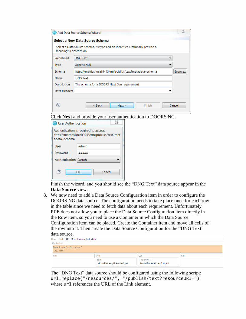
Click Next and provide your user authentication to DOORS NG.
Finish the wizard, and you should see the “DNG Text” data source appear in the
Data Source view.
8. We now need to add a Data Source Configuration item in order to configure the
DOORS NG data source. The configuration needs to take place once for each row
in the table since we need to fetch data about each requirement. Unfortunately
RPE does not allow you to place the Data Source Configuration item directly in
the Row item, so you need to use a Container in which the Data Source
Configuration item can be placed. Create the Container item and move all cells of
the row into it. Then create the Data Source Configuration for the “DNG Text”
data source.
The “DNG Text” data source should be configured using the following script:
url.replace("/resources/", "/publish/text?resourceURI=")
where url references the URL of the Link element.

9. Add Text items to the first and last cells in the row. In the Data Source view find
the element dataSource – artifact – identifier of the “DNG Text” data source
which holds the requirement number. Drag and drop it onto the Text item of the
first cell. Select the Text item and click on the Content tab in the Properties
view. Click the button in the bottom right corner and set the content to the data
expression _value of the “identifier” element.
Repeat the same procedure for the last cell of the row, but this time use the data
source element dataSource – artifact – description.
The row should now look like this:
10. The template is now ready, but before you can generate a report you need to
configure the document specification to provide the authentication information
needed by the “DNG Text” data source:

Also note that if you generate this report for the “DemoRPE” design that is
provided in the Design Room ONE installation, you first need to update the model
in RSAD so that the requirement links point at your DOORS NG server. Then
export the updated model to Design Room ONE and set the DESIGN variable to
the name of the exported design.

11. The final document template looks like this:
And here is what the final report looks like:

Reporting API Reference Design Room ONE provides several REST APIs designed for reporting with RPE. These
APIs all return the data in XML format. If you pass the query parameter
metadata=schema you will get the schema for the returned XML. The REST Schema
Discovery wizard in RPE uses this query parameter to let you interactively browse the
available reporting APIs. All reporting APIs are discoverable using this wizard from the
root reporting URL: /dr/reporting
Reporting URL: /dr/reporting
This is the root reporting API from which all other APIs can be discovered. It provides a
list of Item elements that describe available reporting APIs. The Item elements have the
following nested elements:
• name
The name of the reporting API.
• description
A brief description of what the reporting API does.
• href
The URL of the reporting API.
The following items are currently returned:
• designs
Represents the Designs API.
This reporting API does not support native filtering.
Designs URL: /dr/reporting/designs
Retrieves all designs that are present on a Design Room ONE server. Each design is
represented by a Design element with the following nested elements:
• name
The name of the design.
• id
A unique identifier of the design. This id is not often used since the name of the
design also is unique within the same Design Room ONE server.
• localConfiguration
The name of the design’s local configuration. If the design does not have a local
configuration the element is an empty string.
• href
A URL that describes which reporting APIs that are provided by the design. This
URL is on the form /dr/reporting/designs?design=<name>, where
<name> is the name of the design. If the design has a local configuration it is
specified using an oslc_config.context parameter:

/dr/reporting/designs?design=<name>&oslc_config.context=<localConfigurationName>
The href URL returns a list of Item elements with the same attributes as for the
Reporting API. The following items are currently returned:
o modelElements
Represents the Model Elements API.
o modelRoots
Represents the Model Roots API.
This reporting API supports native filtering. For example, you can use filtering to obtain
a design with a specific name.
Model Roots URL: /dr/reporting/modelRoots?design=<name>
Retrieves the root (i.e. top-level) elements of a design.
If the design has a local configuration the oslc_config.context parameter must also
be provided to specify the local configuration name.
Each root element is represented by a ModelElement element with the following nested
elements:
• metaClass
The meta class of the model element.
• id
The unique identifier of the model element.
• name
The name of the model element. Note that although most model elements have a
name, some don’t. The name is an empty string if the model element does not
have a name.
• icon
A URL that describes the icon of the model element. This URL is on the form
/dr/api/icons/<iconID>, where <iconID> is the unique id of the icon.
• displayName
The string used when displaying the model element in the user interface. For
example, this string is used as the label of the model element’s node in the
Explorer view.
• displayType
The string used when displaying the type (i.e. meta class) of the model element in
the user interface.
• href
A URL that describes the model element. This URL is on the form
/dr/reporting/element?design=<name>&elementId=<id>, where
<name> is the name of the design and <id> is the id of the model element. See
the Element API for more information.

If the design has a local configuration it is specified using an
oslc_config.context parameter:
/dr/reporting/element?design=<name>&oslc_config.context=<localConfigurationName>&elementId=<id>
This reporting API supports native filtering. For example, you can use filtering to obtain
a root element with a specific name.
Model Elements URL: /dr/reporting/modelElements?design=<name>
Retrieves all elements of a design. Each element is represented by a ModelElement
element with the same nested elements as described in the Model Roots API.
If the design has a local configuration the oslc_config.context parameter must also
be provided to specify the local configuration name.
This reporting API supports native filtering. For example, you can use filtering to obtain
all model elements with a specific meta class (for example to retrieve all classes in a
design).
Children URL: /dr/reporting/children?design=<name>&elementId=<id>
Retrieves all immediate children of a model element.
If the design has a local configuration the oslc_config.context parameter must also
be provided to specify the local configuration name.
Each child element is represented by a ModelElement element with the same nested
elements as described in the Model Roots API. Note that only model elements are
returned by this API. Other elements contained in a model element, such as diagrams or
links, are obtained by specific APIs.
This reporting API supports native filtering. For example, you can use filtering to obtain
all children with a specific meta class (for example to retrieve all operations of a class).
Diagrams URL: /dr/reporting/diagrams?design=<name>&elementId=<id>
Retrieves all diagrams of a model element.
If the design has a local configuration the oslc_config.context parameter must also
be provided to specify the local configuration name.

Each diagram is represented by a Diagram element with the following nested elements:
• kind
The kind of diagram (such as Freeform, Sequence etc.).
• id
The unique identifier of the diagram.
• name
The name of the diagram.
• url
The URL from which the diagram image can be obtained. The URL returns the
diagram image as SVG which you can use in a report by means of an Image item.
This reporting API supports native filtering. For example, you can use filtering to obtain
all diagrams of a specific kind.
Links URL: /dr/reporting/links?design=<name>&elementId=<id>
Retrieves all outgoing OSLC links stored on a model element.
If the design has a local configuration the oslc_config.context parameter must also
be provided to specify the local configuration name.
Each link is represented by a Link element with the following nested elements:
• type
The type of link as defined by the OSLC standard (such as Refines, Derives From
etc.)
• label
The label of the link. This is usually the name of the target of the link, for
example the name of a linked requirement.
• linktypedef
The URL that defines the link type. Each type of link has a URL that defines it.
• url
The URL of the target of the link. For example, this could be the URL of a
requirement in DOORS NG.
• projectarea
In case the target of the link is stored in a Jazz CLM product, this specifies the
Jazz project area where it is located.
• server
The URL of the server that hosts the target of the link.
This reporting API supports native filtering. For example, you can use filtering to obtain
all links of a specific type.
Element URL: /dr/reporting/element?design=<name>&elementId=<id>

Retrieves information about a model element.
If the design has a local configuration the oslc_config.context parameter must also
be provided to specify the local configuration name.
The obtained information is represented by a ModelElement element with the following
nested elements:
• metaClass
The meta class of the model element.
• name
The name of the model element. The name is an empty string if the model
element does not have a name.
• id
The unique identifier of the model element.
• icon
A URL that describes the icon of the model element. This URL is on the form
/dr/api/icons/<iconID>, where <iconID> is the unique id of the icon.
• displayName
The string used when displaying the model element in the user interface. For
example, this string is used as the label of the model element’s node in the
Explorer view.
• displayType
The string used when displaying the type (i.e. meta class) of the model element in
the user interface.
• Owner
The owner of the model element. This element has an attribute href which
specifies the URL for getting information about the owner element using the
Element API. The Owner element is not present if the model element is a root
element (i.e. does not have an owner).
• Children
The immediate children of the model element. This element has an attribute href
which specifies the URL for getting the children using the Children API. The
Children element is not present if the model element does not have any children.
• Diagrams
The diagrams contained in the model element. This element has an attribute href
which specifies the URL for getting the diagrams using the Diagrams API. The
Diagrams element is not present if the model element does not have any diagrams.
• Links
The outgoing links stored on the model element. This element has an attribute
href which specifies the URL for getting the links using the Links API. The
Links element is not present if the model element does not have any links.
• Properties
All properties of the model element are represented by means of Property

elements located in the Properties collection. Each Property element has the
following nested elements:
o name
The name of the property.
o value
The value of the property.
• References
All references of the model element are represented by means of Reference
elements located in the References collection. Each Reference element has the
following nested elements:
o name
The name of the reference.
o Target
An element that represents the target of the reference, i.e. the element to
which the reference is bound. The Target element has an attribute href
which specifies the URL for getting information about the target element
using the Element API. The Target element is not present if the reference
is unbound. Some references may have multiple target elements (so called
multi-references). In this case there will be one Target element for each
target element of the reference.
This reporting API does not support native filtering.
Related Documents