Document prepared by ESRI (UK) Ltd Using OS MasterMap ® Integrated Transport Network (ITN) Layer with ArcGIS An ESRI (UK) White Paper Author: ESRI (UK) Reviewer: Ordnance Survey Released: 17/10/2006 Version: 1.2

Welcome message from author
This document is posted to help you gain knowledge. Please leave a comment to let me know what you think about it! Share it to your friends and learn new things together.
Transcript
Document prepared by ESRI (UK) Ltd
Using OS MasterMap® Integrated Transport
Network (ITN) Layer with ArcGIS
An ESRI (UK) White Paper
Author: ESRI (UK)
Reviewer: Ordnance Survey
Released: 17/10/2006
Version: 1.2

Company Confidentiality and Disclaimer Statement This document contains information which is confidential to ESRI (UK) Limited. No part of this document should be reproduced or revealed to third parties without the express permission of ESRI (UK) Limited.
ESRI (UK) Ltd.
Millennium House
65 Walton Street
Aylesbury
Buckinghamshire
HP21 7QG
01296 745 500
01296 745 544 (fax)
www.esriuk.com
Document History
Version Date Changes
0.1 25/11/2005 Document initial release
0.9 20/12/2005 Re-release for external review
0.9.1 16/01/2006 Re-review
0.9.2 09/03/2006 Technology update revision
1.o 29/03/2006 Final release
1.1 30/06/2006 Minor revision to table links
1.2 17/10/2006 Minor revision to network feature extraction instructions
ii of 60 ESRI (UK) Ltd 17/10/2006
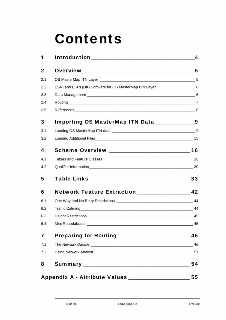
Contents 1 Introduction_______________________________________4
2 Overview__________________________________________5
2.1 OS MasterMap ITN Layer _____________________________________________ 5
2.2 ESRI and ESRI (UK) Software for OS MasterMap ITN Layer __________________ 6
2.3 Data Management ___________________________________________________ 6
2.4 Routing____________________________________________________________ 7
2.5 References_________________________________________________________ 8
3 Importing OS MasterMap ITN Data_______________9
3.1 Loading OS MasterMap ITN data _______________________________________ 9
3.2 Loading Additional Files______________________________________________ 15
4 Schema Overview ______________________________ 16
4.1 Tables and Feature Classes __________________________________________ 16
4.2 Qualifier Information_________________________________________________ 30
5 Table Links _____________________________________ 33
6 Network Feature Extraction____________________ 42
6.1 One Way and No Entry Restrictions ____________________________________ 44
6.2 Traffic Calming_____________________________________________________ 44
6.3 Height Restrictions__________________________________________________ 45
6.4 Mini Roundabouts __________________________________________________ 45
7 Preparing for Routing___________________________ 46
7.1 The Network Dataset ________________________________________________ 46
7.2 Using Network Analyst_______________________________________________ 51
8 Summary________________________________________ 54
Appendix A - Attribute Values _______________________ 55
iii of 60 ESRI (UK) Ltd 17/10/05

1 Introduction The OS MasterMap Integrated Transport Network Layer™ (ITN) is an integral part of the OS MasterMap® product set, along with Topography, Address, and Imagery Layers. Ordnance Survey’s vision of ITN is to provide a detailed overview of Great Britain’s transport infrastructure as a single common multi-modal dataset to meet a variety of business needs, from navigation to asset management, and from traffic analysis to accessibility studies.
Unique identifiers (TOID®) associated with each link and node provide a reference for traffic-flow analysis at crucial junctions, and allow organisations to attach their own data. Examples might be points of interest, traffic incidents or average speeds.
Like other OS MasterMap, ITN contains ‘themes’. The Themes of ITN currently available are:
Road Network – a network representing the roads in Great Britain; and
Road Routing Information (RRI) – data to be associated with Road Network features that may affect a driver’s choice of route; including height and vehicle type restrictions, traffic calming, turn restrictions and one-way roads.
ArcGIS and related products from ESRI (UK) comprise an industry-leading Geographic Information System (GIS) which provides all of the necessary tools for making the most of OS MasterMap data, including ITN Layer.
OS MasterMap ITN, however, is structured in a very particular schema, designed with data delivery efficiency in mind. Working with this data schema is eminently possible, however can seem complex to casual GIS users. This document provides guidance on how best to use ArcGIS with the ITN Layer to maximum effect.
It is anticipated that most users will initially want to use ITN for general cartographic representation and for routing applications. This document, therefore, focuses on these implementations.
4 of 60 ESRI (UK) Ltd 17/10/2006
2 Overview This section covers basic information about OS MasterMap ITN data, as well as a brief overview of the ESRI and ESRI (UK) software products which can be used with it.
2.1 OS MasterMap ITN Layer
The OS MasterMap Integrated Transport Network (ITN) Layer replaces its predecessor, OSCAR™. Like the other vector OS MasterMap products, ITN is delivered in digital files directly from Ordnance Survey in Geographic Markup Language (GML) format, a type of XML. Software is required to interpret and load the ITN GML into a geographic database (See Section 2.2).
Like the other OS MasterMap products, but unlike OSCAR, ITN is delivered ‘to order’ for individual customers through the Ordnance Survey’s on-line ordering service, and according to OS MasterMap data publication dates (available from Ordnance Survey). This means that the Ordnance Survey ‘cut’ the data from the most recent publication date for a particular customer only when they receive an order, and also do the same when updates are requested. This contrasts with the ‘published tile’ push-delivery model for OSCAR.
The customer’s ITN order can be combined within the same GML delivery as the Topography and Address Layers for the same order, or can be split into separate GML files. Either way, the physical delivery of the GML files is made on CD/DVD through the post, or via FTP download (if the total file volume is below the maximum limit, currently 400Mb).
Once an initial delivery (called “Initial Load”) is taken by a customer, the database can then subsequently be kept current through the Ordnance Survey Change-only Update (CoU) system on a time interval, which suits the customer. CoU provides only those features which will have changed in the data holding since the customer’s last delivery.
Alternatively, customers can choose to reload ITN each time. This is a more realistic proposition than it would be for the OS MasterMap Topography Layer, because ITN is much less voluminous.
[Note: At the time of writing of this paper, ESRI/ESRI (UK) software does not support full automatic integration of Change-only Update for ITN Layer; only full re-loads are supported by software. A future release of the Productivity Suite for ArcGIS will support this feature, however the re-loading approach should not create any problems whatsoever for users because the data volume of ‘initial load’ is very manageable.]
See the Ordnance Survey’s OS MasterMap web pages for more detailed information about ordering and delivery: http://www.ordnancesurvey.co.uk/oswebsite/products/osmastermap/index.html.
5 of 60 ESRI (UK) Ltd 17/10/05

Section 4 of this paper describes in detail the structure of the OS MasterMap ITN data itself.
The ITN Layer shares much in common with the Topography Layer. ESRI (UK) have published a white paper, “Loading and Managing OS MasterMap Topography Layer”, which describes in more detail the nature of OS MasterMap itself, its relationship to ESRI software, and guidelines and principles for loading and management. Much of this information applies equally to ITN.
The ESRI (UK) “Loading and Managing OS MasterMap Topography Layer” white paper can be found on the ESRI (UK) website:
http://www.esriuk.com/products/OS_MasterMap.asp
2.2 ESRI and ESRI (UK) Software for OS MasterMap ITN Layer
All ESRI and ESRI (UK) software products can work with ITN data once it is imported into a geodatabase. “Working with data”, however, has two aspects: the data loading and management; and then the use in analysis. The analysis use of ITN data is in areas such as cartography, routing, and asset management. Because of the complex nature of the ITN schema, it is in these areas in which it is perceived that customers require some guidance. This paper focuses therefore on products and methods useful for these application areas.
ArcGIS, as a full-featured GIS, is the centrepiece of the suite of applications and therefore this document will make use of terms and concepts which reference it in various ways.
2.3 Data Management
ESRI (UK)’s MapManager extension for ArcGIS has supported the loading of the ITN layer since 2003. MapManager version 9.1.2 (and above), however, contains many important cumulative improvements to the ITN interpreter, so it is important to use that version.
Productivity Suite for ArcGIS is a new product from ESRI (UK), scheduled for release in early 2006. Productivity Suite replaces MapManager and five other ESRI (UK) extensions. All of MapManager’s functionality, however, exists within the new application.
The new Productivity Suite from ESRI (UK) is a complete set of tools for:
• Ordnance Survey data conversion, including the OS MasterMap ITN Layer • Data maintenance and change management • Analysis • Place-finding and locating • Housing estate management tools
This document will normally refer to and include diagrams and illustrations of Productivity Suite.
ESRI’s Data Interoperability Extension (“Interop”) also reads OS MasterMap, including the OS MasterMap ITN Layer. Interop, however, is especially suited for ‘direct-read’ (reading directly without first loading into a database) of the GML files, and for use within Geoprocessing Models created within ArcGIS. This is very useful
6 of 60 ESRI (UK) Ltd 17/10/05

for previewing the data within ArcCatalog or ArcMap before loading; however it is less suited for complete ‘management’ of an OS MasterMap database, partly because it has no capacity for incorporating Change-only Update, and partly because it doesn’t do any interpretation of the schema without user intervention. Because MapManager and its successor, Productivity Suite, are built specifically for wizard-based implementation of OS MasterMap layers, and automatic integration of CoU, these products are recommended to most users and are the focus of this document.
The result of the import process with MapManager and Productivity Suite is a relational model of the OS MasterMap ITN data which, as has been mentioned, is supplied originally in GML format. This schema is very rich, but also potentially complex for users, and at present there are few automated tools to help users get ‘up and running’ quickly with value-added applications like Network Analyst (for routing). ESRI (UK) are endeavouring to create software which helps bridge this gap, but in the mean time this paper is offered to help provide guidance to GIS users for ways to become productive immediately with OS MasterMap ITN data.
OS MasterMap ITN data is delivered from Ordnance Survey with or without Road Route Information (RRI). This document assumes that RRI has been included.
2.4 Routing
Within ArcGIS, routing processes are performed with the Network Analyst extension. Network Analyst enhances ArcGIS capabilities by adding:
• Routing • Closest facility • Service area analysis • Advanced network management and creation
Network Analyst can be used for a number of analyses, from classic point-to-point routing to advanced time-based delivery models across millions of features. Using the advanced features in the new Network model, users can do even more with their data.
The product delivers advanced features of the Network Model including:
• Closest Facility • Complex multi-part turns • Dynamic impedance • Global weights • Scaleable to multi-users • Exact and hierarchical routing • Network barrier support
Network-based spatial analysis is available for ArcGIS Desktop (ArcView, ArcEditor, or ArcInfo), ArcGIS Engine, and ArcGIS Server. For desktop users, ArcGIS Network Analyst provides a rich environment with easy to use menus and tools, as well as the robust functionality available in the geoprocessing environment for modelling and scripting. ArcGIS Engine and ArcGIS Server users can employ the APIs of the optional Network Extension to provide customized network solutions in a deployed custom application, or as a server-based application. These, essentially, allow the full range of features of ArcGIS to be used in a variety of distributed ways.
ArcView 3.x Network Analyst users will find all their familiar tools available in ArcGIS Network Analyst. In addition, ArcGIS Network Analyst has improved the core
7 of 60 ESRI (UK) Ltd 17/10/05

functionalities and added new features. ArcGIS Network Analyst requires ArcView, ArcEditor, or ArcInfo [4].
2.5 References
[1] Ordnance Survey (2005) OS MasterMap® User Guide: Reference Section v6.0
[2] ESRI (2005) Preparing Street Data for Use with the Network Dataset – An ESRI Technical Paper
[3] White, M (2005) Guide to OS MasterMap Integrated Transport Network (ITN) Tables and Relates in ESRI Map Manager 9.
[4] ESRI (2005) ArcGIS Network Analyst Product Overview - http://www.esri.com/software/arcgis/extensions/networkanalyst/about/overview.html
[5] ESRI (UK) (2005) ESRI (UK) Productivity Suite Brochure.
[6] Ordnance Survey (2005) - OS MasterMap ITN Technical Demonstration http://www.ordnancesurvey.co.uk/oswebsite/products/osmastermap/demos/itn_tech/index.html
8 of 60 ESRI (UK) Ltd 17/10/05

3 Importing OS MasterMap ITN Data
This section provides a quick guide to loading OS MasterMap ITN data. ESRI (UK) MapManager and its Productivity Suite equivalent are universal Ordnance Survey data loaders, and they are required tools for this process. It is strongly recommended that Productivity Suite OS MasterMap Converter or MapManager 9.1.2 (or higher) is used to load ITN data.
First it is necessary to have available the GML files containing ITN Layer data. These can be read directly from the Ordnance Survey CD/DVD, or can be first copied onto local storage media.
Depending on the choices made by the user at the time of placing the OS MasterMap order with Ordnance Survey, the GML files delivered may contain only ITN, or may also contain OS MasterMap Topography Layer and OS MasterMap Address Layer. OS MasterMap Converter and MapManager handle both of these situations.
GML files are normally delivered in ‘chunks’, which usually represent 5km-square areas of coverage; however some users will choose to take ‘non-geographic chunks’, which are divided according to equal file size.
Please refer to the Ordnance Survey web site, or ESRI (UK)’s “Loading and Managing OS MasterMap Topography Layer” white paper for more detailed discussion of OS MasterMap, GML files, chunks, and delivery and processing options.
3.1 Loading OS MasterMap ITN data
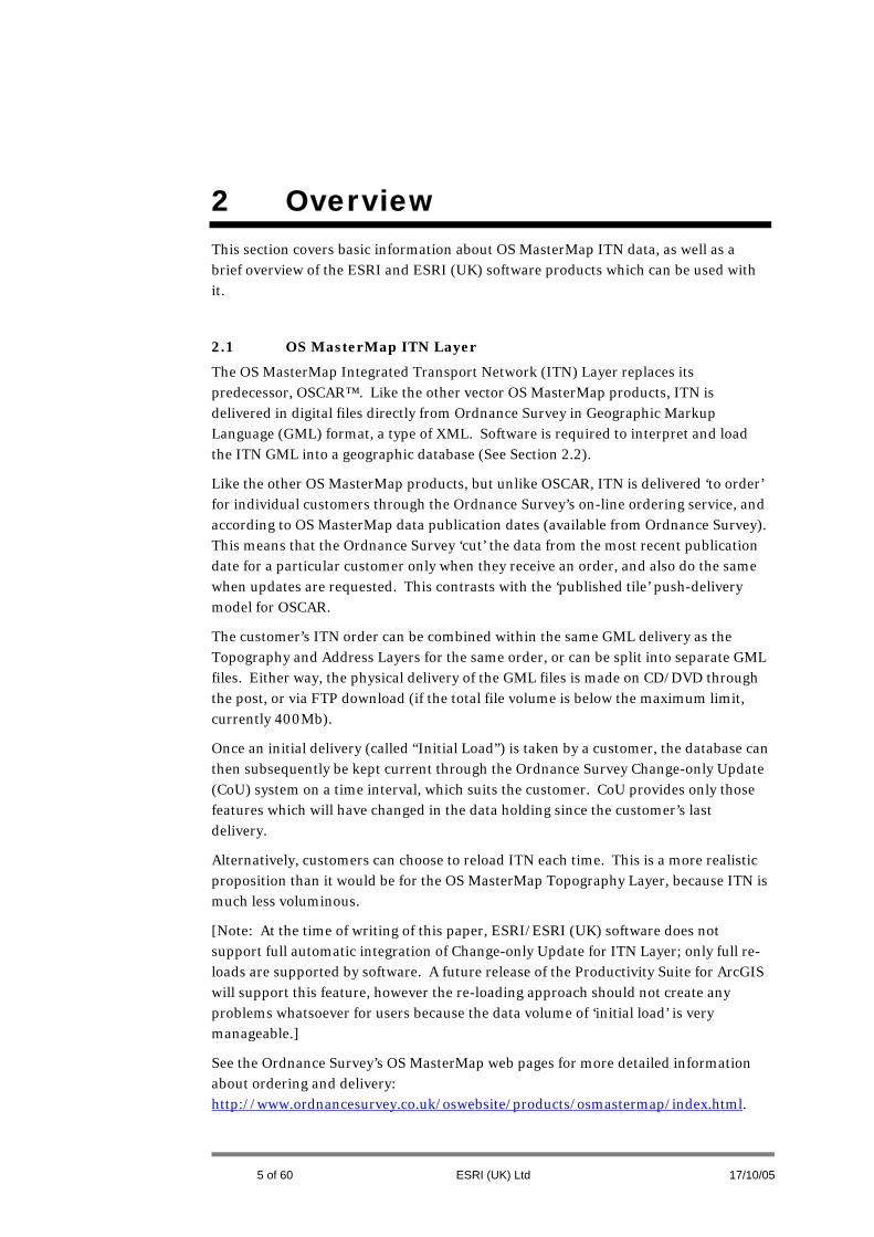
The following sequence shows steps which can be taken to load OS MasterMap ITN data. Productivity Suite OS MasterMap Converter will be accessible from ArcCatalog or from the Windows Program menu. For MapManager users, remember that the same functionality is also available from ArcCatalog or from the Windows Program menu. Figure 3.1.1 shows the OS MasterMap Converter start up screen. Click Next to continue.
9 of 60 ESRI (UK) Ltd 17/10/05
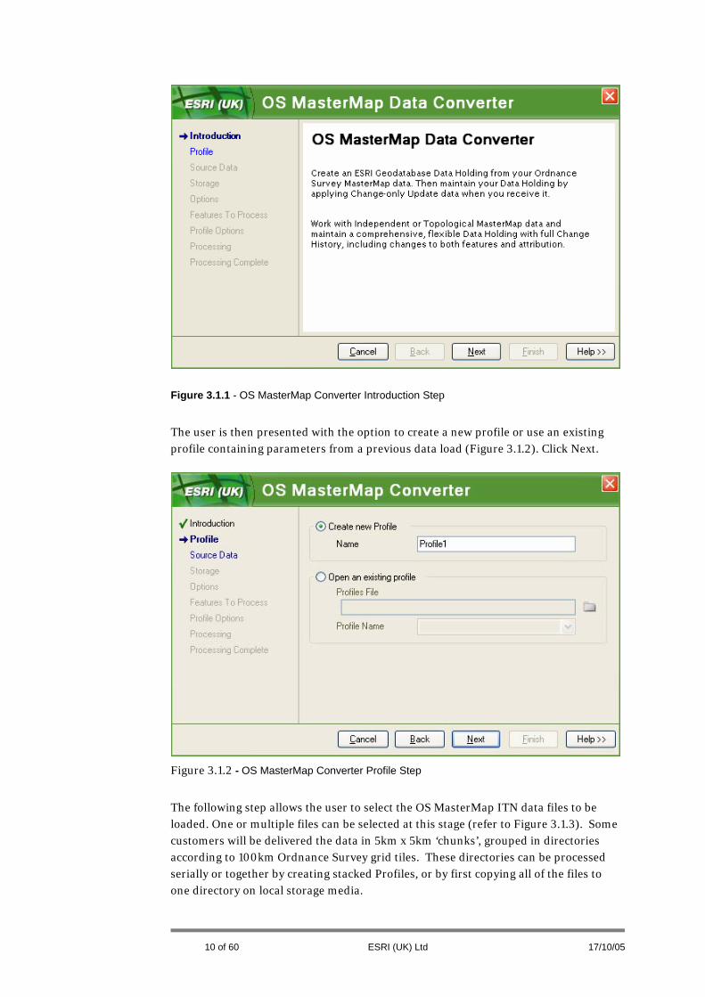
Figure 3.1.1 - OS MasterMap Converter Introduction Step
The user is then presented with the option to create a new profile or use an existing profile containing parameters from a previous data load (Figure 3.1.2). Click Next.
Figure 3.1.2 - OS MasterMap Converter Profile Step
The following step allows the user to select the OS MasterMap ITN data files to be loaded. One or multiple files can be selected at this stage (refer to Figure 3.1.3). Some customers will be delivered the data in 5km x 5km ‘chunks’, grouped in directories according to 100km Ordnance Survey grid tiles. These directories can be processed serially or together by creating stacked Profiles, or by first copying all of the files to one directory on local storage media.
10 of 60 ESRI (UK) Ltd 17/10/05

This step also gives the option to apply a Change-Only Update. For OS MasterMap ITN data do not tick this option. Click Next.
Figure 3.1.3 - OS MasterMap Converter Source Data Step
The following stage (refer to Figure 3.1.4) is important as it controls the configuration of the geodatabase into which the data is loaded. There are options here to load the data into an existing Personal Geodatabase or ArcSDE database; or alternatively a new Personal Geodatabase can be created. To create a new ArcSDE database, refer to the ArcSDE user guide.
At this stage a prefix can be added to the default table names. For example, if the prefix was specified to be ITN then the RdLk table (which stores road links) would be called ITN_RdLk. The purpose of the prefix is to help the users identify quickly within ArcCatalog (for example) which Tables and Feature Classes belong to ITN (as opposed to Topography Layer, for example).
11 of 60 ESRI (UK) Ltd 17/10/05
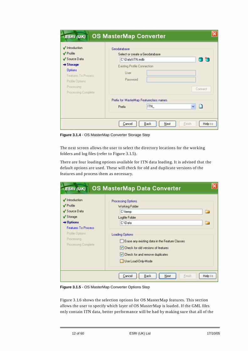
Figure 3.1.4 - OS MasterMap Converter Storage Step
The next screen allows the user to select the directory locations for the working folders and log files (refer to Figure 3.1.5).
There are four loading options available for ITN data loading. It is advised that the default options are used. These will check for old and duplicate versions of the features and process them as necessary.
Figure 3.1.5 - OS MasterMap Converter Options Step
Figure 3.1.6 shows the selection options for OS MasterMap features. This section allows the user to specify which layer of OS MasterMap is loaded. If the GML files only contain ITN data, better performance will be had by making sure that all of the
12 of 60 ESRI (UK) Ltd 17/10/05
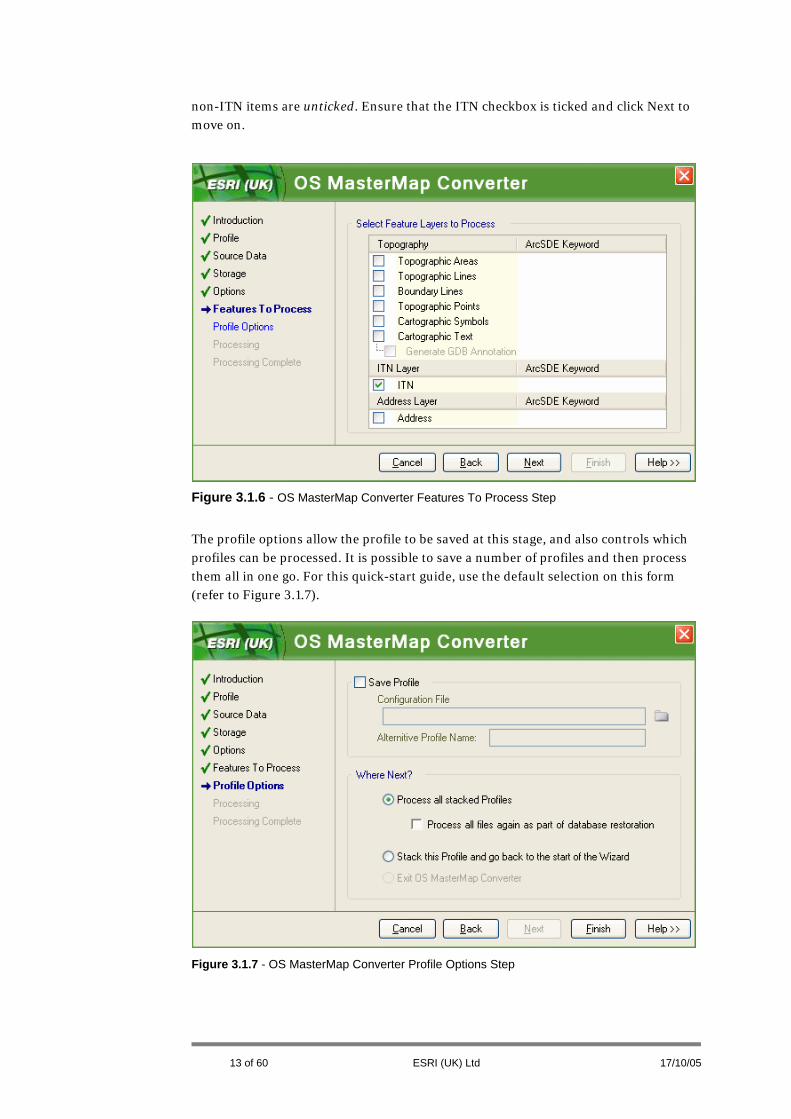
non-ITN items are unticked. Ensure that the ITN checkbox is ticked and click Next to move on.
Figure 3.1.6 - OS MasterMap Converter Features To Process Step
The profile options allow the profile to be saved at this stage, and also controls which profiles can be processed. It is possible to save a number of profiles and then process them all in one go. For this quick-start guide, use the default selection on this form (refer to Figure 3.1.7).
Figure 3.1.7 - OS MasterMap Converter Profile Options Step
13 of 60 ESRI (UK) Ltd 17/10/05

Clicking Next from the Profile Options form (Figure 3.1.7) will start the loading process running (Figure 3.1.8). All ITN files added earlier in the process will then be loaded, with progress information being updated on the screen.
Figure 3.1.8 - OS MasterMap Converter Processing Step
Upon completion of the loading process the user will be presented with the screen shown in Figure 3.1.9. This gives the user the opportunity to inspect the log file.
Figure 3.1.9 - OS MasterMap Data Processing Complete Step
14 of 60 ESRI (UK) Ltd 17/10/05

3.2 Loading Additional Files
The documented sequence of events in the previous section covers the initial loading of ITN data. However, if the user wants to add data to that which has been previously loaded then some amendments to the flow are required. The steps covered by Figure 3.1.1 to Figure 3.1.3 are the same.
When setting the database options (as shown in Figure 3.1.4) ensure that the same database is used. At this step choose Create New for the prefix option, but use the same prefix as before. For example, if a prefix called ITN_ was used then re-enter this information.
The rest of the steps will remain the same.
15 of 60 ESRI (UK) Ltd 17/10/05

16 of 60 ESRI (UK) Ltd 17/10/05
4 Schema Overview
4.1 Tables and Feature Classes
This section provides information on the content of the database tables after loading OS MasterMap ITN data, and how they relate to the original GML.
Table 4.1 provides a summary description of each of the main tables that result after loading ITN data, along with extracts from the original GML. These tables can be subsequently associated to provide further information.

Table Name
ESRI Feature
Type
ITN GML Representation Description
RdNd PointFeature Class
These are road nodes. A node signifies the beginning or end of road link. Road nodes are formed at the start or end of a road, or where a road junction occurs.
17 of 60 ESRI (UK) Ltd 17/10/2006

RNA Table
Road Node Association. Provides a TOID lookup to relate to the areas in the OS MasterMap Topography Layer. The highlighted box in the GML show the Topographic Area the Road Node is associated with.
RdLk Line FeatureClass
A road can be comprised of one or more Road Link features (lines). These road links are stored in this table. This the key table for road network use.
18 of 60 ESRI (UK) Ltd 17/10/05

RLA Table
Road Link Association. Provides a TOID lookup to relate to the areas in the Topography Layer. Highlighted box in the GML extract shows the Topographic Areas the Road Link is associated with.
ROAD PolygonFeature Class
Contains polygons representing the MBR of each Road (the total road links). Holds additional description information (e.g. whether the road is a primary route or trunk road)
19 of 60 ESRI (UK) Ltd 17/10/05

RRN Table
Table containing a road names and the Road TOIDs (not Road Link TOIDs) to which they apply.
RRL Table
Lookup table to associate Roads to Road Links. A Road is made up of 1 or more Road links. The GML extract shows the Road Links forming the road named Cornforth Road.
20 of 60 ESRI (UK) Ltd 17/10/05

InPt PointFeature Class
Information Points currently represent Motorway junctions. They do not form part of the road network.
RNI Table
Road Node Information. This provides a lookup between Qualifier information / restriction and Road Nodes. This can be used to identify features such as mini roundabouts.
21 of 60 ESRI (UK) Ltd 17/10/05

RLI PointFeature Class
Road Link Information describes a condition which affects a Road Link irrespective of direction. It can effect the whole of the Road Link or just a point along the Link. This feature class contains a 1:1 relationship with Road Links.
The first GML extract shows an example of a condition affecting an entire road link and the second example shows GML for a condition that affects a point at a location on a link.
22 of 60 ESRI (UK) Ltd 17/10/05

RPLI Multi PointFeature Class
Road Partial Link Information. A Partial Road Link Restriction occurs where a section of a road link has a restriction irrespective of direction. A point represents the start of the restriction and another represent the end of the restriction.
23 of 60 ESRI (UK) Ltd 17/10/05

RRI PointFeature Class
Road Route Information. Contains restriction locations for Routes and has a 1:M relationship with Road Links. These conditions affect links in a specified direction.
When more than 1 Road Link TOID is specified, it is not possible to travel from one Link to the other.
RPRI Multi PointFeature Class
Road Partial Route Information. A Partial Road Link Restriction occurs where a section of a Road Link has a restriction in a specified direction. A point represents the start of the restriction and another represents the end of the restriction.
24 of 60 ESRI (UK) Ltd 17/10/05
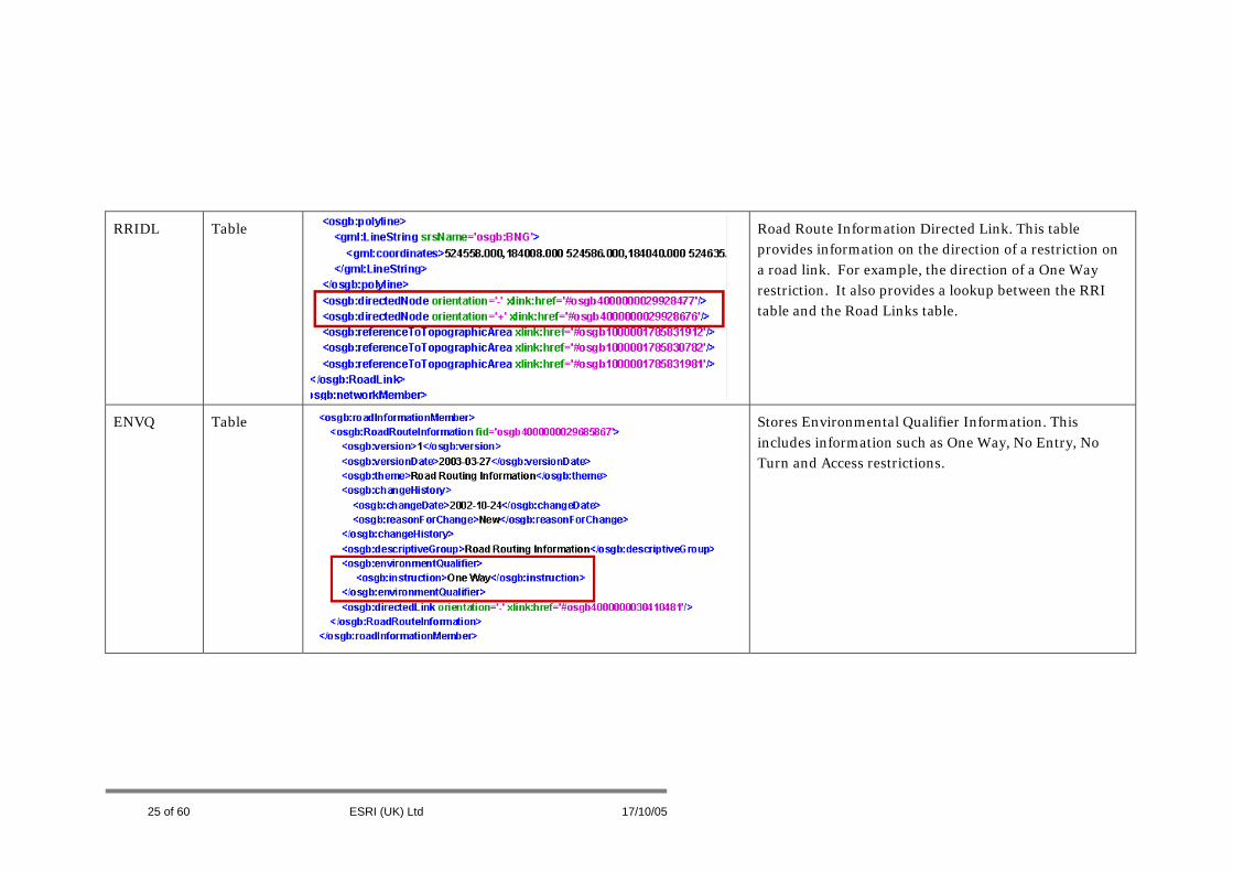
RRIDL Table
Road Route Information Directed Link. This table provides information on the direction of a restriction on a road link. For example, the direction of a One Way restriction. It also provides a lookup between the RRI table and the Road Links table.
ENVQ Table
Stores Environmental Qualifier Information. This includes information such as One Way, No Entry, No Turn and Access restrictions.
25 of 60 ESRI (UK) Ltd 17/10/05

VQ Table
Vehicle Qualifier Information. Contains information stating which types of vehicle (e.g. buses, taxis etc) can (or cannot) access road links.
VHEIGHTQ Table
Vehicle Height Qualifiers. Contains height restriction information for road links.
26 of 60 ESRI (UK) Ltd 17/10/05
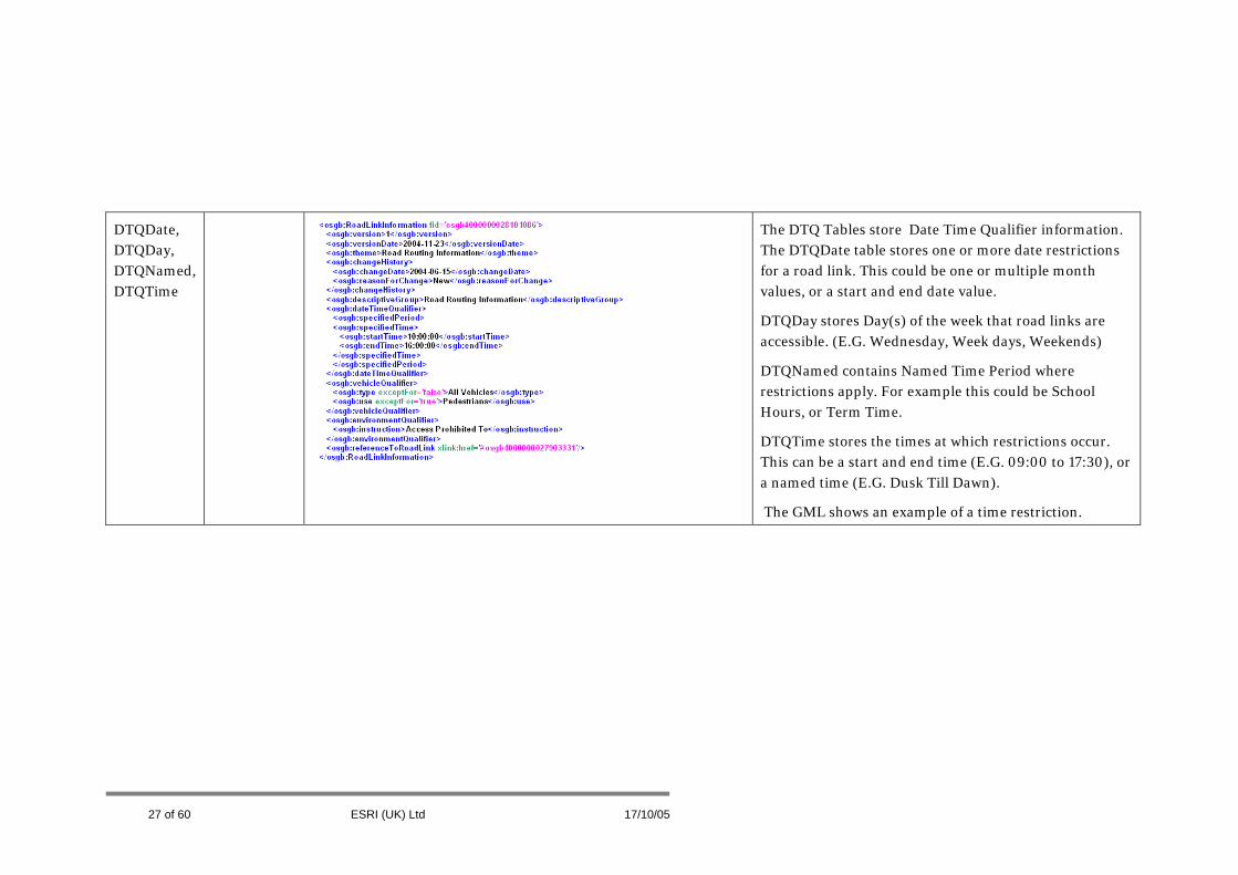
DTQDate, DTQDay, DTQNamed, DTQTime
The DTQ Tables store Date Time Qualifier information. The DTQDate table stores one or more date restrictions for a road link. This could be one or multiple month values, or a start and end date value.
DTQDay stores Day(s) of the week that road links are accessible. (E.G. Wednesday, Week days, Weekends)
DTQNamed contains Named Time Period where restrictions apply. For example this could be School Hours, or Term Time.
DTQTime stores the times at which restrictions occur. This can be a start and end time (E.G. 09:00 to 17:30), or a named time (E.G. Dusk Till Dawn).
The GML shows an example of a time restriction.
27 of 60 ESRI (UK) Ltd 17/10/05

FyNd PointFeature Class
Ferry Nodes. These occur at the beginning and end of each Ferry Link.
FyLk Line FeatureClass
Contains Ferry Links for Vehicular Ferries.
28 of 60 ESRI (UK) Ltd 17/10/05

29 of 60 ESRI (UK) Ltd 17/10/05
FyTl Table
Contains Ferry Terminal Information. No geometry of its own but it is associated with the Ferry Node table.
FyTlLkUp Table
Ferry Terminal Lookup Table. Contains information to connect a Ferry Terminal to a Ferry Node feature and the link on the network.
Table 4.1 – GML and Database Table Content (GML screen shots provided by Ordnance Survey [6].)

4.2 Qualifier Information
Table 4.1 showed that the ENVQ, VQ, VHEIGHTQ and the DTQ tables store the qualifier information that forms the Road Routing Information (RRI). The RRI is information which will affect the choice made on a route. These instructions and restrictions require further examination to explain how they work in combination to provide information.
The tables highlighted in Figure 4.2.1 show those which form the RRI. The arrows in the diagram indicate whether the relationships are one-to-one or one-to-many. These RRI tables are used with the Qualifier tables to associate the restrictions and instructions with Road Links and Nodes.
Figure 4.2.1 - Entity diagram showing table associations which indicate Route Features [6] (Taken from the Ordnance Survey web site – OS MasterMap ITN Layer Technical Demonstrator: http://www.ordnancesurvey.co.uk/oswebsite/products/osmastermap/demos/itn_tech/pages/introduction.html )
The Environmental Qualifiers (ENVQ) determine what the restriction is, the Vehicle Qualifiers (VQ and VHEIGHTQ tables) control who the information is applied to, and the Date Time Qualifiers (DTQ tables) specify when the restrictions occur. This is best illustrated by example.
Environmental qualifiers can be used by themselves or in conjunction with other qualifier types. For example, a One Way restriction on a Road Link will just use information from the ENVQ table along with direction information.
Vehicle qualifiers are always used in conjunction with an instruction from an Environmental qualifier. This can be shown in Figure 4.2.2 where a Road Link has access limited to buses and cycles.
30 of 60 ESRI (UK) Ltd 17/10/2006

Environmental Qualifier:
Access Limited To
Vehicle Qualifier:
Type (exceptfor = false) = Buses Type (exceptfor = false) = Cycles
Figure 4.2.2 - Vehicle Qualifier Example 1
Figure 4.2.3 shows an example where a Vehicle Qualifier is used in conjunction with an Environmental Qualifier and a Date Time Qualifier.
Figure 4.2.3 - Vehicle Qua
Similarly to Vehicle Quawith other Qualifier typQualifier is used in conjQualifier. The final exaan Environmental Qualrestriction between 8am
31 of 60
Date Time Qualifier
Specified Time StartTime = 08:00 EndTime = 18:00
Environmental Qualifier:
Access Prohibited To
Vehicle Qualifier:
Type (exceptfor = true) = Buses Use (exceptfor = true) = Taxis Use (exceptfor = true) = Permit Holders
lifier Example 2
lifiers, Date Time Qualifiers are always used in conjunction es. The previous example illustrated this where a Date Time unction with an Environmental Qualifier and Vehicle mple (Figure 4.2.4) shows use of a Date Time Qualifier with ifier only. This models a Road Link which has a No Entry and 8pm.
ESRI (UK) Ltd 17/10/05

Figure 4.2.4 - Date Time Qual
32 of 60
Date Time Qualifier
Specified Time StartTime = 08:00 EndTime = 20:00
Environmental Qualifier:
No Entry
ifier Example
ESRI (UK) Ltd 17/10/05

5 Table Links The previous section explained what is contained in each Feature Class and Table after loading ITN, and how the content relates back to the original GML. This section provides information on how to make use of the data. The data is complex to model as many of the relationships are one-to-many (1:M). This is apparent when examining road names. A road may have more than one name, in the form of a name and the DfT number. For example Hills Road in Cambridge is also the A1307.
After adding the loaded ITN data into ArcMap, these relationships can be modelled using a Relate operation. A Relate operation can easily be performed in ArcMap by right clicking on the first Feature Class or table required in the Relate operation and then selecting the option shown in Figure 5.1.
Figure 5.1 - Relate Operation Selection
33 of 60 ESRI (UK) Ltd 17/10/05
34 of 60 ESRI (UK) Ltd 17/10/05
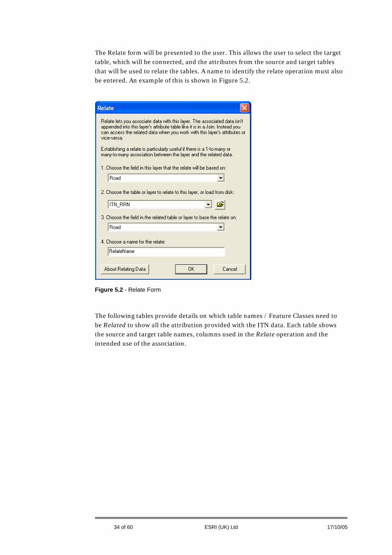
Figure 5.2 - Relate Form
The Relate form will be presented to the user. This allows the user to select the target table, which will be connected, and the attributes from the source and target tables that will be used to relate the tables. A name to identify the relate operation must also be entered. An example of this is shown in Figure 5.2.
The following tables provide details on which table names / Feature Classes need to be Related to show all the attribution provided with the ITN data. Each table shows the source and target table names, columns used in the Relate operation and the intended use of the association.

Source table name Column to relate Target table name Column to relate Suggested Name Use
RRN Road to RRL Road RRN2RRL Road Names
RRL RoadLink to RdLk TOID RRL2RDLK Road Names
RRI TOID to RRIDL TOID RRI2RRIDL Route Restrictions
RRIDL DirectedLinkTOID to RdLk TOID RRIDL2RDLK Route Restrictions
RPRI DirectedLinkTOID to RdLk TOID RPRI2RDLK Partial Restrictions
RLI RoadLinkTOID to RdLk TOID RLI2RDLK Partial Restrictions
RPLI RoadLinkTOID to RdLk TOID RPLI2RDLK Partial Restrictions
ENVQ TOID to RRI TOID ENVQ2RRI Environmental Qualifiers
ENVQ TOID to RPRI TOID ENVQ2RPRI Environmental Qualifiers
ENVQ TOID to RLI TOID ENVQ2RLI Environmental Qualifiers
ENVQ TOID to RPLI TOID ENVQ2RPLI Environmental Qualifiers
VQ TOID to RRI TOID VQ2RRI Vehicle Qualifiers
VQ TOID to RPRI TOID VQ2RPRI Vehicle Qualifiers
VQ TOID to RLI TOID VQ2RLI Vehicle Qualifiers
VQ TOID to RPLI TOID VQ2RPLI Vehicle Qualifiers
VHEIGHTQ TOID to RLI TOID VHEIGHTQ2RLI Vehicle Height Qualifiers
DTQDATE TOID to RRI TOID DATE2RRI Date Time Qualifiers
DTQDATE TOID to RPRI TOID DATE2RPRI Date Time Qualifiers
35 of 60 ESRI (UK) Ltd 17/10/2006

DTQDATE TOID to RLI TOID DATE2RLI Date Time Qualifiers
DTQDATE TOID to RPLI TOID DATE2RPLI Date Time Qualifiers
DTQDAY TOID to RRI TOID DAY2RRI Date Time Qualifiers
DTQDAY TOID to RPRI TOID DAY2RPRI Date Time Qualifiers
DTQDAY TOID to RLI TOID DAY2RLI Date Time Qualifiers
DTQDAY TOID to RPLI TOID DAY2RPLI Date Time Qualifiers
DTQNAMED TOID to RRI TOID NAMED2RRI Date Time Qualifiers
DTQNAMED TOID to RPRI TOID NAMED2RPRI Date Time Qualifiers
DTQNAMED TOID to RLI TOID NAMED2RLI Date Time Qualifiers
DTQNAMED TOID to RPLI TOID NAMED2RPLI Date Time Qualifiers
DTQTIME TOID to RRI TOID TIME2RRI Date Time Qualifiers
DTQTIME TOID to RPRI TOID TIME2RPRI Date Time Qualifiers
DTQTIME TOID to RLI TOID TIME2RLI Date Time Qualifiers
DTQTIME TOID to RPLI TOID TIME2RPLI Date Time Qualifiers
RdLk NODE1 TO RdNd TOID RDLK2RDND1 Links to Nodes
RdLk NODE2 TO RdNd TOID RDLK2RDND2 Links to Nodes
RLA ROADLINK to RdLk TOID RLA2RDLK Link to Topographic Layer
Figure 5.3 - Relate Operations for Road Links
36 of 60 ESRI (UK) Ltd 17/10/05

37 of 60 ESRI (UK) Ltd 17/10/05
Source Table name
Column to relate Target Table name Column to relate Suggested Name Use
RNI RoadNodeTOID RdNdto TOID RNI2RDND Link to Qualifiers
ENVQ TOID to RNI TOID ENVQ2RNI Environmental Qualifiers
VHeightQ TOID to RNI TOID VHQ2RNI Vehicle Height Qualifiers
RNA RoadNode to RDND TOID RNA2RDND Link to Topographic Layer
Figure 5.4 - Relate Operations for Road Nodes

The results from Relate operations can be interrogated in ArcMap. Using the Identify Tool to examine a Road Link (RdLk) or Road Node (RdNd) will show all the related information. The user can drill down through the related features to see all of their attributes. The following series of diagrams gives some examples to demonstrate this. In each case the data displayed is OS MasterMap Topography Layer overlain with the ITN layer.
Figure 5.5 shows the result from clicking on a Road Link which forms part of Newmarket Road in Cambridge. The Identify Results show all the information related to the Road Link. By expanding the RRL value it can be seen that 2 values for RRN are present. This means there are 2 Road Names for this Road Link. The first Identify Results example shows that the Road Name is Newmarket Road. The second example shows that it is also the A1134.
38 of 60 ESRI (UK) Ltd 17/10/2006

Figure 5.5 - Road Name and Number
Figure 5.6 shows an example of some One Way streets. In the diagram the One Way streets are represented by an arrow. From using the Identify Tool on one of these Road Links the user can drill down through the related RRIDL and RRI tables to reveal the ENVQ value. This indicates that the Road Link has a One Way restriction.
39 of 60 ESRI (UK) Ltd 17/10/05

Figure 5.6 - One Way Street Example
The Road Nodes can be used to identify some network features. For example Figure 5.7 shows some mini roundabouts. By using Identify on the Road node the user can drill down to the related ENVQ information to see that there is a mini roundabout at this node.
40 of 60 ESRI (UK) Ltd 17/10/05

Figure 5.7 - Road Node Example
41 of 60 ESRI (UK) Ltd 17/10/05
6 Network Feature Extraction The previous section discussed the interrogation of the data after conducting multiple Relate operations. However, for some of the features which have one-to-one relationships (1:1) with Road Links or Road Nodes, standard ArcMap tools can be used to identify them and export to another Feature Class if necessary. Examples are given to identify the following characteristics of a Road Network:
• One Way Streets
• No Entry Restrictions
• Roads with Traffic Calming
• Height Restrictions
• Mini Roundabouts
It is recommended that the following operations are conducted on a sample test dataset before attempting on a larger quantity of data.
As previously stated, some of the relationships in the data are one-to-one rather than one-to-many or many-to-one. This means that rather than a Relate operation, a Join operation can be used. Unlike a Relate operation the results of this (joined information) can be viewed through the ArcMap Attribute table, and can be queried using the Selection by Attribute tool.
The Join function can be accessed by right clicking on the first table or Feature Class to be used in the process. This is shown in Figure 6.1 which also shows the resulting Join form.
42 of 60 ESRI (UK) Ltd 17/10/05

Figure 6.1 - The Join Operation
43 of 60 ESRI (UK) Ltd 17/10/05

6.1 One Way and No Entry Restrictions
To identify One Way and No Entry restrictions, two tables and the Road Links Feature Class need to be joined. The parameters for these joins are displayed in Table 6.1.1.
The RRIDL table contains the direction of the restriction. When joined to the ENVQ table the One Way and No Entry values will then have a + or – associated with them. The + value indicates a restriction from beginning to end of the Road Link and vice-versa for a – value.
After the first join has been made, the resultant information then needs to be joined to the Road Links (RDLK) Feature Class. Prior to doing this, the user may wish to export the joined tables. This will increase performance of subsequent operations. From the Join form, the target table will now be listed in a form similar to RRIDL_ENVQ because these tables were joined in the first operation (alternatively an exported table containing the results from the first join can be used instead).
Source Table /
FC
Join Field Target Table / FC Join Field
RRIDL TOID ENVQ TOID
RDLK TOID RRIDL_ENVQ RRIDL.DIRECTEDLINKTOID
Table 6.1.1 - One Way and No Entry Restrictions
Upon completing the joins, the Road Links will effectively have extra attribution including No Entry and One Way restrictions. These can be identified using the Attribute Selection tool to select Qualifier attribute values which equal One Way or No Entry. Optionally, the selection can then be exported to a separate Feature Class or Shapefile.
The results from these Join operations consider Road Links where the whole Road Link has the restrictions. Partial Road Link restrictions are not considered in these examples. Caution needs to be taken with the use of the No Entry information as it is often required to be used in conjunction with Date Time Qualifier data.
6.2 Traffic Calming
A similar procedure can be used to identify Road Links with Traffic Calming restrictions. The difference is that Traffic Calming features apply irrespective of direction. Therefore the RLI table is used in the Join process instead of the RRIDL.
The required parameters are shown in Table 6.2.1. After the first join has been made, the joined table needs to be exported to another Feature Class. The exported Feature Class can then be joined to the Road Links (RDLK) Feature Class. The result of this process will have a Qualifier field with the value of Traffic Calming indicating which Road Links have Traffic Calming measures.
44 of 60 ESRI (UK) Ltd 17/10/05

Source Table /
FC
Join Field Target Table / FC Join Field
RLI TOID ENVQ TOID
RDLK TOID RLI_ENVQ RLI.ROADLINKTOID
Table 6.2.1 - Traffic Calming Example
6.3 Height Restrictions
The height restriction information in OS MasterMap ITN data can be utilised to identify Bridge Over Roads and the Road Link on which these restrictions occur. Joining the VHEIGHTQ table to the ENVQ table (refer to Table 6.3.1) will allow Bridges Over Roads to be identified. Looking at the Qualifier attribute will confirm this. Where information in the RLI Feature Class has an x and y attribute value, a point feature is constructed. Therefore joining the RLI table with the result of the first join will allow bridges that occur over roads to be identified. The results of the second table join will need to be exported to another Feature Class prior to the final join. The third row in Table 6.3.1 shows how to apply the final join to the Road Link on which the Bridge occurs to show the height restriction.
Source Table
/ FC
Join Field Target Table / FC Join Field
VHEIGHTQ TOID ENVQ TOID
RLI TOID VHEIGHTQ_ENVQ VHEIGHTQ.TOID
RDLK TOID RLI_VHEIGHTQ_ENVQ RLI.ROADLINKTOID
Table 6.3.1 - Bridge Over Roads
6.4 Mini Roundabouts
Mini Roundabouts can be identified using the Road Node Information (RNI) as each one will occur at a road junction. Table 6.4.1 shows the Join parameters required to achieve this. The results of the first table join will need to be exported to another Feature Class prior to the second table join. The result will be evident in the form of an attribute named Qualifier on the Road Node feature.
Source Table /
FC
Join Field Target Table / FC Join Field
RNI TOID ENVQ TOID
RDND TOID RNI_ENVQ RNI.ROADNODETOID
Table 6.4.1 - Mini Roundabouts
45 of 60 ESRI (UK) Ltd 17/10/05
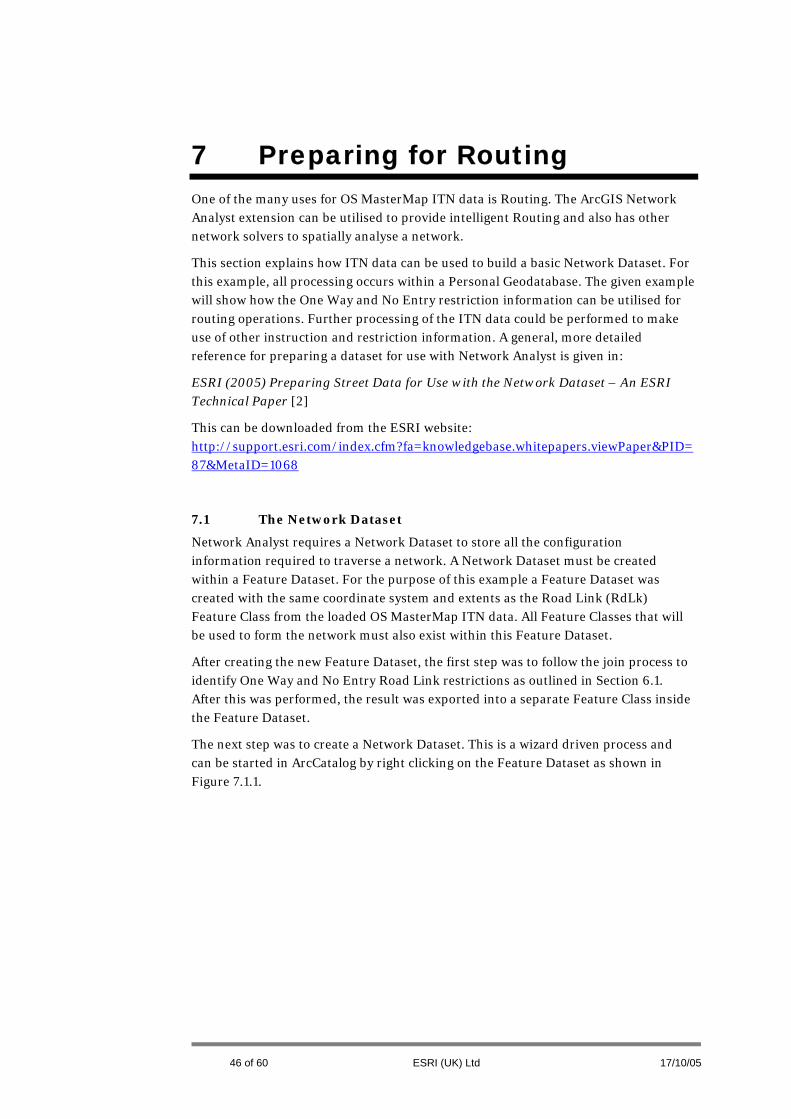
7 Preparing for Routing One of the many uses for OS MasterMap ITN data is Routing. The ArcGIS Network Analyst extension can be utilised to provide intelligent Routing and also has other network solvers to spatially analyse a network.
This section explains how ITN data can be used to build a basic Network Dataset. For this example, all processing occurs within a Personal Geodatabase. The given example will show how the One Way and No Entry restriction information can be utilised for routing operations. Further processing of the ITN data could be performed to make use of other instruction and restriction information. A general, more detailed reference for preparing a dataset for use with Network Analyst is given in:
ESRI (2005) Preparing Street Data for Use with the Network Dataset – An ESRI Technical Paper [2]
This can be downloaded from the ESRI website: http://support.esri.com/index.cfm?fa=knowledgebase.whitepapers.viewPaper&PID=87&MetaID=1068
7.1 The Network Dataset
Network Analyst requires a Network Dataset to store all the configuration information required to traverse a network. A Network Dataset must be created within a Feature Dataset. For the purpose of this example a Feature Dataset was created with the same coordinate system and extents as the Road Link (RdLk) Feature Class from the loaded OS MasterMap ITN data. All Feature Classes that will be used to form the network must also exist within this Feature Dataset.
After creating the new Feature Dataset, the first step was to follow the join process to identify One Way and No Entry Road Link restrictions as outlined in Section 6.1. After this was performed, the result was exported into a separate Feature Class inside the Feature Dataset.
The next step was to create a Network Dataset. This is a wizard driven process and can be started in ArcCatalog by right clicking on the Feature Dataset as shown in Figure 7.1.1.
46 of 60 ESRI (UK) Ltd 17/10/05

Figure 7.1.1 - The Network Dataset
The first steps in the wizard prompt for a Network Dataset name and the input Feature Classes which will form the network. In this example, the only input will be the processed Road Links dataset. The next option allows control over connectivity. This is which features connect and how. The default was accepted for this option.
Elevation properties can then be set (refer to Figure 7.1.2). This controls how roads which cross but do not connect behave. A fly-over is an example of this situation.
Figure 7.1.2 - Elevation Properties
47 of 60 ESRI (UK) Ltd 17/10/05

The ITN data stores this elevation data by setting an integer value and the start and end of each Road Link. These are stored in the Node1GradeSeparation and Node2GradeSeparation attributes and can be entered as shown in Figure 7.1.2.
Road Links can only connect if they have the same value at the connection node. An example is shown in Figure 7.1.3. In the first situation where 4 Road Links join, they all have NodeGradeSeparation values of 0. This means that turns can be made from Road A to Road B and vice-versa. However, in the second situation Road A has NodeGradeSeparation values of 1 at the intersection point. This means that Road A is above Road B at this point and therefore manoeuvres cannot be made between the 2 roads.
Figure 7.1.3 -Road Link Connection
The next stage in the process is to select whether Turn Restriction Features are to be used in the Network Dataset. These are not considered in this example. For more information on these refer to [2].
The following key stage is the setting of network properties. This controls how the network is traversed in terms of journey costs and restrictions. The data used in this example uses 3 properties which can be viewed in Figure 7.1.4.
48 of 60 ESRI (UK) Ltd 17/10/05

Figure 7.1.4 - Network Attributes
These were added manually using the interface. After adding the properties their values need to be set. These can be constant values, Feature Class attributes or calculated values. The form to set these can be accessed via the Evaluators button. The Length property is a cost and its value is set to the shape_Length attribute which is the calculated Length of the Road Link. This means that when a network is traversed this property will be used to find the shortest route.
One Way and No Entry are restrictions. These are set via expressions. Figure 7.1.5 shows the Evaluators form. To set the One Way restrictions for the Road Links data there is a From-To direction and a To-From direction. The Type of these was set to Field and the Value to <expression>, rather than a specific Road Link attribute field. The Evaluators button was then used to set up the Field Evaluators. This allows logic to be applied to calculate whether a Road Link is restricted or not. This logic is applied in the form of VB Script.
Figure 7.1.6 shows the logic to calculate whether a Road Link in the To-From direction is restricted. A check is performed to see if the Qualifier attribute of the Road Link has a value of One Way. If this is true, then the value of the DirectedLinkOrientation is checked. If this value is found to be +, then the Road Link is set as restricted. The same process is used for From-To direction, but the DirectedLinkOrientation is restricted if a – value is present.
49 of 60 ESRI (UK) Ltd 17/10/05
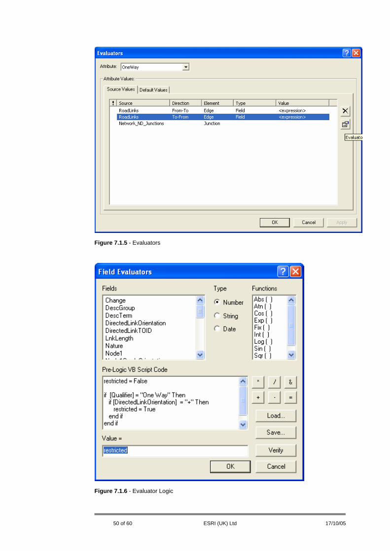
Figure 7.1.5 - Evaluators
Figure 7.1.6 - Evaluator Logic
50 of 60 ESRI (UK) Ltd 17/10/05
After the properties were set the final option was to generate driving directions. This was not included for this example, but this facility allows Road Names to be set so they are included in directions generated for a route.
The Network Dataset was then created and built. The build process constructs the Network Dataset in accordance with the parameters set during the configuration process which has been outlined. After completion of the build process, the Network Dataset is ready for use in Network Analyst.
7.2 Using Network Analyst
This section provides a simple example on how to perform point-to-point routing on a network built from ITN data. It examines how to make use of the restriction information set up in section 7.1. For further information on the capabilities of Network Analyst refer to the Network Analyst Tutorial which is supplied with the extension. Additionally, information can be found in the ArcGIS help.
The Network Analyst Extension has its own toolbar and a window to output Network Analysis information. From the toolbar the user has the option to create a new route. Upon doing so, the user can then set (digitise or load) the start and end points for a route (and any intermediate points). There are also analysis settings which can be configured so that any available parameters such as restrictions can be switched on. After this information has been set the network can be solved to show the route between the locations.
Figure 7.2.1 shows a screenshot of a route solved between 2 points. The route has been generated without setting the network solver to use Road Link restrictions. Figure 7.2.2 shows the same area with the One Way streets rendered as arrows in the display. This shows if restrictions are considered it would be incorrect for a vehicle to take the generated route between the 2 points. Accessing the Route Layer Properties will display the Analysis Settings. The Restrictions section of this form as displayed in Figure 7.2.3 shows that No Entry and One Way restrictions can be used as parameters in solving the network. Checking the boxes to activate these and re-generating the route now produces a different result which avoids One Way streets as shown in Figure 7.2.4.
51 of 60 ESRI (UK) Ltd 17/10/05

Figure 7.2.1 - Route 1
Figure 7.2.2 - Analysis Settings
52 of 60 ESRI (UK) Ltd 17/10/05

Figure 7.2.3 - One Way Streets
Figure 7.2.4 - Route 2
53 of 60 ESRI (UK) Ltd 17/10/05

8 Summary
This paper has provided an overview on how to get started with the OS MasterMap ITN Layer using ESRI and ESRI (UK) software focussing on:
• The key features of OS MasterMap ITN Layer • How to process load ITN into a geodatabase • A description of the resulting ITN schema tables • Details about how to use these tables • How to associate all the ITN attribution, so that users can identify
information and restrictions applicable to road links and nodes. • Identifying and extracting road network features from the data. • Potential uses for the ITN Layer. A dataset was prepared for use within the
ArcGIS Network Analyst Extension and a road network was traversed to show routing between locations and the influence of road restrictions on that route.
The steps taken in this paper will allow users to more quickly get started with ITN data and ESRI software.
As was previously stated, a future version of the ESRI (UK) Productivity Suite will include additional data processing tools for ITN. The aim of these tools will be to facilitate the ease of use of ITN within ArcMap and Network Analyst, by automating many of the tasks outlined in this paper (and more). This will result in a schema which can be used for applications such as Routing and Asset Management.
It is envisaged that the schema generation process will be an interactive sequence of events (“wizard”-based approach) which will permit the user to select the information required for their application use.
For the latest news on the Productivity Suite please refer to the ESRI (UK) website at
http://www.esriuk.com/products/productivitysuite/products.asp.
54 of 60 ESRI (UK) Ltd 17/10/05

Appendix A - Attribute Values For some of the attributes in the OS MasterMap ITN data it is useful to know the range of values that they can have. The following information shows values currently outlined in the MasterMap specification [1] for several of the key information types.
RDLK
DescTerm Nature
A Road Slip Road
A Road Dual Carriageway
A Road Traffic Island Link
A Road Roundabout
A Road Single Carriageway
A Road Traffic Island Link At Junction
Alley Slip Road
Alley Traffic Island Link
Alley Traffic Island Link At Junction
Alley Enclosed Traffic Area Link
Alley Single Carriageway
B Road Traffic Island Link
B Road Slip Road
B Road Dual Carriageway
B Road Roundabout
B Road Traffic Island Link At Junction
B Road Single Carriageway
Local Street Traffic Island Link
Local Street Slip Road
Local Street Dual Carriageway
Local Street Roundabout
Local Street Traffic Island Link At Junction
Local Street Single Carriageway
Local Street Enclosed Traffic Area Link
Minor Road Traffic Island Link
Minor Road Slip Road
Minor Road Dual Carriageway
Minor Road Roundabout
55 of 60 ESRI (UK) Ltd 17/10/05

Minor Road Traffic Island Link At Junction
Minor Road Single Carriageway
Minor Road Enclosed Traffic Area Link
Motorway Dual Carriageway
Motorway Roundabout
Motorway Slip Road
Motorway Traffic Island Link At Junction
Motorway Single Carriageway
Pedestrian Street Slip Road
Pedestrian Street Dual Carriageway
Pedestrian Street Roundabout
Pedestrian Street Traffic Island Link
Pedestrian Street Traffic Island Link At Junction
Private Road – Publicly Accessible Slip Road
Private Road – Publicly Accessible Dual Carriageway
Private Road – Publicly Accessible Roundabout
Private Road – Publicly Accessible Traffic Island Link
Private Road – Publicly Accessible Enclosed Traffic Area Link
Private Road – Publicly Accessible Traffic Island Link At Junction
Private Road – Publicly Accessible Single Carriageway
Private Road – Restricted Access Traffic Island Link
Private Road – Restricted Access Dual Carriageway
Private Road – Restricted Access Roundabout
Private Road – Restricted Access Single Carriageway
Private Road – Restricted Access Traffic Island Link At Junction
Private Road – Restricted Access Slip Road
Private Road – Restricted Access Enclosed Traffic Area Link
ENVQ
Qualifier Type
Bridge Over Road Classification
Firing Range Classification
Ford Classification
Gate Classification
56 of 60 ESRI (UK) Ltd 17/10/05

Level Crossing Classification
Mini Roundabout Classification
Rising Bollards Classification
Severe Turn Classification
Through Route Classification
Toll Indicator Classification
Traffic Calming Classification
Access Limited To Instruction
Access Prohibited To Instruction
Mandatory Turn Instruction
No Entry Instruction
No Turn Instruction
One Way Instruction
DTQDATE
NamedDate StartDate EndDate
NULL --04-01 --09-30
NULL --05-01 --09-30
August NULL NULL
July NULL NULL
June NULL NULL
May NULL NULL
September NULL NULL
DTQDAY
DAY
Monday
Tuesday
Wednesday
Thursday
Friday
Saturday
57 of 60 ESRI (UK) Ltd 17/10/05

Sunday
Weekdays
Weekends
DTQNAMED
NamedPeriod
School Hours
Term Time
DTQTIME
NamedTime
Local Times Apply
Dusk Till Dawn
Dawn Till Dusk
Day
NULL
VQ
Qualifier QualifierType ExceptFor
Access Use True
Access Use False
Authorised Vehicles Use True
Authorised Vehicles Use False
Disabled Use True
Disabled Use False
Emergency Access Use True
Emergency Access Use False
Emergency Vehicles Use True
Emergency Vehicles Use False
Loading And Unloading Use True
Loading And Unloading Use False
Local Buses Use True
Local Buses Use False
Official Business Use False
58 of 60 ESRI (UK) Ltd 17/10/05

Patrons Use False
Pedestrians Use True
Pedestrians Use False
Permit Holders Use True
Permit Holders Use False
Petrol Tankers Use True
Petrol Tankers Use False
Public Transport Use True
Public Transport Use False
Residents And Guests Use True
Residents And Guests Use False
School Buses Use True
School Buses Use False
Service Vehicles Use True
Service Vehicles Use False
Taxis Use True
Taxis Use False
Works Traffic Use False
All Vehicles Type True
All Vehicles Type False
Buses Type True
Buses Type False
Coaches Type True
Coaches Type False
Cycles Type True
Cycles Type False
HGVs Type True
HGVs Type False
LGVs Type True
LGVs Type False
Mopeds Type True
Mopeds Type False
Motor Cycles Type True
Motor Cycles Type False
59 of 60 ESRI (UK) Ltd 17/10/05

Motor Vehicles Type True
Motor Vehicles Type False
Towed Caravans Type True
Tracked Vehicles Type False
Abnormal Loads Type True
Dangerous Goods Type False
Wide Loads Type True
Wide Loads Type False
60 of 60 ESRI (UK) Ltd 17/10/05
Related Documents