4201 E Arkansas Avenue Denver, CO 80222 (303) 512-5204 http://www.dot.state.co.us/DesignSupport/ Colorado Department of Transportation Using InRoads Survey for Data Reduction CADD and Engineering Innovation Updated November 10, 2009 Version DRAFT

Welcome message from author
This document is posted to help you gain knowledge. Please leave a comment to let me know what you think about it! Share it to your friends and learn new things together.
Transcript

4201 E Arkansas AvenueDenver, CO 80222(303) 512-5204http://www.dot.state.co.us/DesignSupport/
Colorado Department of Transportation
Using InRoads Survey for Data Reduction
CADD and Engineering InnovationUpdated November 10, 2009Version DRAFT

Page 2 Colorado Department of Transportation
Using InRoads Survey for Data Reduction
Colorado Department of Transportation Page 3
Using InRoads Survey for Data Reduction
This document has been prepared for the Colorado Department of Transportation by:
And the following Sub-consultants:
Copyright
Copyright © 2009 Colorado Department of Transportation. All Rights Reserved
Many of the designations used by manufacturers and sellers to distinguish their products are claimed as trademarks. MicroStation and InRoads are trademarks of Bentley Systems Incorporated. Where other designations appear in this book, and the authors were aware of a trademark claim, the designations have been capitalized.
The Colorado Department of Transportation (CDOT) has accepted this document. By accepting this document, CDOT assumes ownership and all responsibilities associated with this document. This information is subject to change without notice
Disclaimer
Notice of Disclaimer: CDOT provides documents on an “as is” basis. All warranties and representations of any kind with regard to said documents are disclaimed, including the implied warranties of merchantability and fitness for a particular use. Under no circumstances will CDOT, or any of its officers or employees be liable for any consequential, incidental, special or exemplary damages even if appraised of the likelihood of such damages occurring. CDOT does not warrant the documents against deficiencies of any kind. The use of any of these documents for work which is under contract with CDOT, does not relieve the contractor from any obligation assumed by the contract, or from complete and proper fulfillment of the terms of the contract, nor does it entitle the contractor to compensation for damages or loss which could be attributed to such use.
Notice
This manual may be freely copied or distributed for the purpose of providing the Colorado Department of Transportation and Colorado customers a consistent guide to using the Bentley suite of products to meet CDOT's design and drafting standards.
Software Versions
The software products referred to in this publication are furnished under a license and may only be used in accordance with the terms of such license. This document intended for use with the following software versions:
MicroStation® version 08.09.04.88InRoads® version 08.09.02.160209 – Version 04.00 CDOT Configuration
Colorado Department of TransportationProject Development BranchCDOT CADD Department4201 East Arkansas Ave., Rm 290Denver, CO 80222www.dot.state.co.us
Bohannan Huston, Inc.Meridian One9785 Maroon CircleSuite 140 Englewood, CO 80112-5919www.bhinc.com
The Envision Group8517 Excelsior DriveSuite 205Madison, WI 53717www.envisioncad.com
Page 4 Colorado Department of Transportation
Using InRoads Survey for Data Reduction
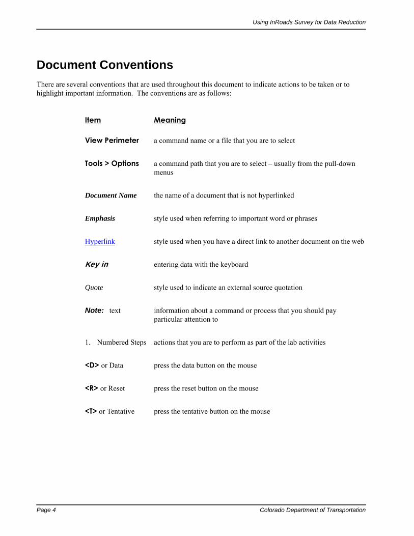
Document Conventions
There are several conventions that are used throughout this document to indicate actions to be taken or to highlight important information. The conventions are as follows:
Item
Meaning
View Perimeter a command name or a file that you are to select
Tools > Options a command path that you are to select – usually from the pull-down menus
Document Name the name of a document that is not hyperlinked
Emphasis style used when referring to important word or phrases
Hyperlink style used when you have a direct link to another document on the web
Key in entering data with the keyboard
Quote style used to indicate an external source quotation
Note: text information about a command or process that you should pay particular attention to
1. Numbered Steps actions that you are to perform as part of the lab activities
<D> or Data press the data button on the mouse
<R> or Reset press the reset button on the mouse
<T> or Tentative press the tentative button on the mouse

Using InRoads Survey for Data Reduction Page 5
Table of Contents
Document Conventions . . . . . . . . . . . . . . . . . . . . . . . . . . . . . . . . . . . . . . . . . . . . . . . . . 4
Chapter 1 - Introduction to CDOTAn Introduction to CDOT XM Configuration . . . . . . . . . . . . . . . . . . . . . . . . . . . . . . 9
Reference Material . . . . . . . . . . . . . . . . . . . . . . . . . . . . . . . . . . . . . . . . . . . . . . . . . . . . . 9
A Practical Guide for Using MicroStation XM . . . . . . . . . . . . . . . . . . . . . . . . . . . . . . . . . 9
A Practical Guide for Using InRoads XM . . . . . . . . . . . . . . . . . . . . . . . . . . . . . . . . . . . . . 9
Lab Material . . . . . . . . . . . . . . . . . . . . . . . . . . . . . . . . . . . . . . . . . . . . . . . . . . . . . . . . . 10
Labs for Using MicroStation XM . . . . . . . . . . . . . . . . . . . . . . . . . . . . . . . . . . . . . . . . . . 10
Labs for Using InRoads XM . . . . . . . . . . . . . . . . . . . . . . . . . . . . . . . . . . . . . . . . . . . . . .11
Training Directory Structure . . . . . . . . . . . . . . . . . . . . . . . . . . . . . . . . . . . . . . . . . . . .11
Training Directory Structure . . . . . . . . . . . . . . . . . . . . . . . . . . . . . . . . . . . . . . . . . . . . . 12
How To Get Help . . . . . . . . . . . . . . . . . . . . . . . . . . . . . . . . . . . . . . . . . . . . . . . . . . . . . 12
CDOT CADD & Engineering Innovation Website . . . . . . . . . . . . . . . . . . . . . . . . . . 12CADD & Engineering Processes . . . . . . . . . . . . . . . . . . . . . . . . . . . . . . . . . . . . . . . 13CADD Manager. . . . . . . . . . . . . . . . . . . . . . . . . . . . . . . . . . . . . . . . . . . . . . . . . . . 13
Chapter 2 - Getting Started with InRoads SurveyInRoads Survey Interface . . . . . . . . . . . . . . . . . . . . . . . . . . . . . . . . . . . . . . . . . . . . . . 15
Menu Bar. . . . . . . . . . . . . . . . . . . . . . . . . . . . . . . . . . . . . . . . . . . . . . . . . . . . . . . . . . . 15
Workspace Bar. . . . . . . . . . . . . . . . . . . . . . . . . . . . . . . . . . . . . . . . . . . . . . . . . . . . . . . 16
Information Window. . . . . . . . . . . . . . . . . . . . . . . . . . . . . . . . . . . . . . . . . . . . . . . . . . . 16
Status Bar . . . . . . . . . . . . . . . . . . . . . . . . . . . . . . . . . . . . . . . . . . . . . . . . . . . . . . . . . . 16
Project Defaults . . . . . . . . . . . . . . . . . . . . . . . . . . . . . . . . . . . . . . . . . . . . . . . . . . . . . . . 17
Dialog Items . . . . . . . . . . . . . . . . . . . . . . . . . . . . . . . . . . . . . . . . . . . . . . . . . . . . . . . . 17
Toolbars . . . . . . . . . . . . . . . . . . . . . . . . . . . . . . . . . . . . . . . . . . . . . . . . . . . . . . . . . . . 18
Survey Toolbar . . . . . . . . . . . . . . . . . . . . . . . . . . . . . . . . . . . . . . . . . . . . . . . . . . . 19View Survey Data Toolbar . . . . . . . . . . . . . . . . . . . . . . . . . . . . . . . . . . . . . . . . . . . 19Locks Toolbar . . . . . . . . . . . . . . . . . . . . . . . . . . . . . . . . . . . . . . . . . . . . . . . . . . . . 20Docked Toolbars . . . . . . . . . . . . . . . . . . . . . . . . . . . . . . . . . . . . . . . . . . . . . . . . . . 20
Survey Options - General Tab. . . . . . . . . . . . . . . . . . . . . . . . . . . . . . . . . . . . . . . . . . . 21
Dialog Items . . . . . . . . . . . . . . . . . . . . . . . . . . . . . . . . . . . . . . . . . . . . . . . . . . . . . . . . 21
Survey Options - Units Tab . . . . . . . . . . . . . . . . . . . . . . . . . . . . . . . . . . . . . . . . . . . . . 23
Survey Options - Symbology Tab . . . . . . . . . . . . . . . . . . . . . . . . . . . . . . . . . . . . . . . . 24
Chapter 3 - Working with InRoads Survey – OverviewFieldbook Data dialog . . . . . . . . . . . . . . . . . . . . . . . . . . . . . . . . . . . . . . . . . . . . . . . . . 25
Dialog Items . . . . . . . . . . . . . . . . . . . . . . . . . . . . . . . . . . . . . . . . . . . . . . . . . . . . . . . . 26
Duplicate Points General Rules:. . . . . . . . . . . . . . . . . . . . . . . . . . . . . . . . . . . . . . . . . . . 28
Rule # 1 . . . . . . . . . . . . . . . . . . . . . . . . . . . . . . . . . . . . . . . . . . . . . . . . . . . . . . . . 28Rule #2 . . . . . . . . . . . . . . . . . . . . . . . . . . . . . . . . . . . . . . . . . . . . . . . . . . . . . . . . . 28
Stations . . . . . . . . . . . . . . . . . . . . . . . . . . . . . . . . . . . . . . . . . . . . . . . . . . . . . . . . . . . . 29
Chainage . . . . . . . . . . . . . . . . . . . . . . . . . . . . . . . . . . . . . . . . . . . . . . . . . . . . . . . . . . . 29

Page 6 Colorado Department of Transportation
Using InRoads Survey for Data Reduction
Observations . . . . . . . . . . . . . . . . . . . . . . . . . . . . . . . . . . . . . . . . . . . . . . . . . . . . . . . . . 29
Chapter 4 - Exporting the Fieldbook – OverviewWrite Survey Data to Graphics dialog . . . . . . . . . . . . . . . . . . . . . . . . . . . . . . . . . . . . 31
Dialog Items: . . . . . . . . . . . . . . . . . . . . . . . . . . . . . . . . . . . . . . . . . . . . . . . . . . . . . . . . 31
Planarize. . . . . . . . . . . . . . . . . . . . . . . . . . . . . . . . . . . . . . . . . . . . . . . . . . . . . . . . . . . . 31
Curve Stroking Modes. . . . . . . . . . . . . . . . . . . . . . . . . . . . . . . . . . . . . . . . . . . . . . . . . . 32
Survey Data to Surface dialog . . . . . . . . . . . . . . . . . . . . . . . . . . . . . . . . . . . . . . . . . . . 33
Dialog Items: . . . . . . . . . . . . . . . . . . . . . . . . . . . . . . . . . . . . . . . . . . . . . . . . . . . . . . . . 33
Curve Stroking Mode . . . . . . . . . . . . . . . . . . . . . . . . . . . . . . . . . . . . . . . . . . . . . . . 34Always Use: . . . . . . . . . . . . . . . . . . . . . . . . . . . . . . . . . . . . . . . . . . . . . . . . . . . . . . 34Triangulate Surface . . . . . . . . . . . . . . . . . . . . . . . . . . . . . . . . . . . . . . . . . . . . . . . . . 34
Triangulate Surface dialog . . . . . . . . . . . . . . . . . . . . . . . . . . . . . . . . . . . . . . . . . . . . . . 35
Dialog items: . . . . . . . . . . . . . . . . . . . . . . . . . . . . . . . . . . . . . . . . . . . . . . . . . . . . . . . . 35
Multiple Feature coding and the DTM . . . . . . . . . . . . . . . . . . . . . . . . . . . . . . . . . . . . 36
Survey Data to Geometry dialog . . . . . . . . . . . . . . . . . . . . . . . . . . . . . . . . . . . . . . . . . 38
Dialog Items: . . . . . . . . . . . . . . . . . . . . . . . . . . . . . . . . . . . . . . . . . . . . . . . . . . . . . . . . 38
Curve Stroking . . . . . . . . . . . . . . . . . . . . . . . . . . . . . . . . . . . . . . . . . . . . . . . . . . . . . . . 38
Chapter 5 - Importing DataResolving Code Error dialog . . . . . . . . . . . . . . . . . . . . . . . . . . . . . . . . . . . . . . . . . . . . 39
Dialog Items: . . . . . . . . . . . . . . . . . . . . . . . . . . . . . . . . . . . . . . . . . . . . . . . . . . . . . . . . 39
Resolving Code Errors options . . . . . . . . . . . . . . . . . . . . . . . . . . . . . . . . . . . . . . . . . . 39
Suggestions. . . . . . . . . . . . . . . . . . . . . . . . . . . . . . . . . . . . . . . . . . . . . . . . . . . . . . . . . . 39
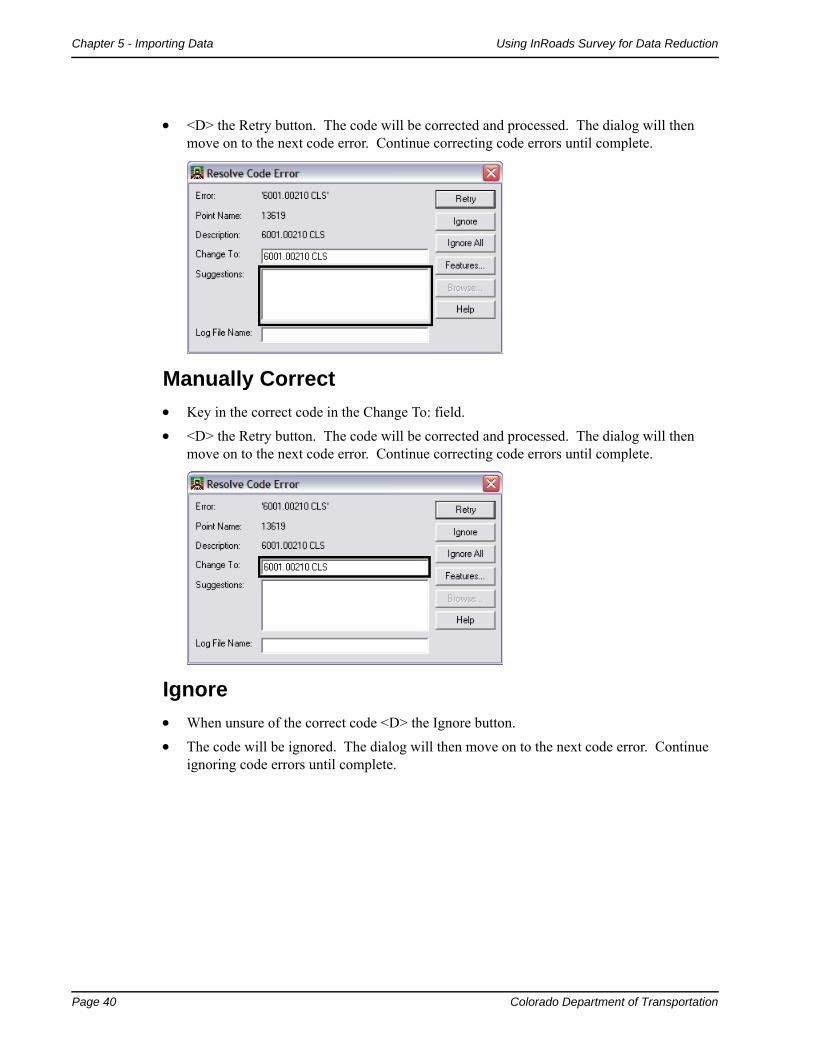
Manually Correct . . . . . . . . . . . . . . . . . . . . . . . . . . . . . . . . . . . . . . . . . . . . . . . . . . . . . 40
Ignore. . . . . . . . . . . . . . . . . . . . . . . . . . . . . . . . . . . . . . . . . . . . . . . . . . . . . . . . . . . . . . 40
Ignore All . . . . . . . . . . . . . . . . . . . . . . . . . . . . . . . . . . . . . . . . . . . . . . . . . . . . . . . . . . . 41
Saving Error Results . . . . . . . . . . . . . . . . . . . . . . . . . . . . . . . . . . . . . . . . . . . . . . . . . . . 41
Finding Points in a MicroStation View . . . . . . . . . . . . . . . . . . . . . . . . . . . . . . . . . . . . 42
Dialog items: . . . . . . . . . . . . . . . . . . . . . . . . . . . . . . . . . . . . . . . . . . . . . . . . . . . . . . . . 42
Chapter 6 - Feature Codes and Control CodesStyle Manager dialog . . . . . . . . . . . . . . . . . . . . . . . . . . . . . . . . . . . . . . . . . . . . . . . . . . . 43
Dialog Filtering: . . . . . . . . . . . . . . . . . . . . . . . . . . . . . . . . . . . . . . . . . . . . . . . . . . . 44 Feature Editing: . . . . . . . . . . . . . . . . . . . . . . . . . . . . . . . . . . . . . . . . . . . . . . . . . . . 45Edit Style dialog . . . . . . . . . . . . . . . . . . . . . . . . . . . . . . . . . . . . . . . . . . . . . . . . . . . 46Control Codes. . . . . . . . . . . . . . . . . . . . . . . . . . . . . . . . . . . . . . . . . . . . . . . . . . . . . 53
Chapter 7 - Fieldbook EditsFieldbook Data dialog . . . . . . . . . . . . . . . . . . . . . . . . . . . . . . . . . . . . . . . . . . . . . . . . . . 71
Find Observation dialog . . . . . . . . . . . . . . . . . . . . . . . . . . . . . . . . . . . . . . . . . . . . . . . . 72
Dialog items: . . . . . . . . . . . . . . . . . . . . . . . . . . . . . . . . . . . . . . . . . . . . . . . . . . . . . . . . 72
Edit Observation dialog . . . . . . . . . . . . . . . . . . . . . . . . . . . . . . . . . . . . . . . . . . . . . . . . 73
Dialog items: . . . . . . . . . . . . . . . . . . . . . . . . . . . . . . . . . . . . . . . . . . . . . . . . . . . . . . . . 73
Chapter 8 - Exporting the FieldbookFinal Export and save . . . . . . . . . . . . . . . . . . . . . . . . . . . . . . . . . . . . . . . . . . . . . . . . . . 75

Colorado Department of Transportation Page 7
Using InRoads Survey for Data Reduction
Chapter 9 - DTM EvaluationSurface Properties dialog . . . . . . . . . . . . . . . . . . . . . . . . . . . . . . . . . . . . . . . . . . . . . . . 77
Dialog Items . . . . . . . . . . . . . . . . . . . . . . . . . . . . . . . . . . . . . . . . . . . . . . . . . . . . . . . . . 77
Data File Naming & Saving . . . . . . . . . . . . . . . . . . . . . . . . . . . . . . . . . . . . . . . . . . . . . 78

Page 8 Colorado Department of Transportation
Using InRoads Survey for Data Reduction
Colorado Department of Transportation Page 9
Chapter 1 - Introduction to CDOT
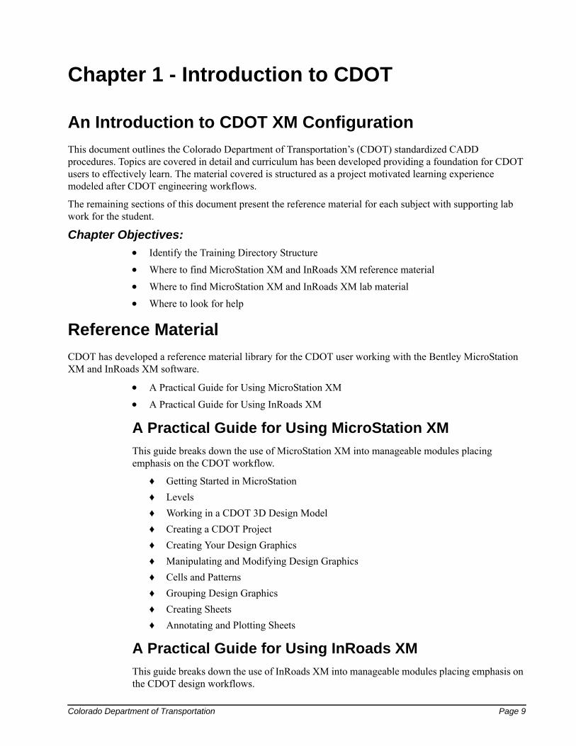
An Introduction to CDOT XM Configuration
This document outlines the Colorado Department of Transportation’s (CDOT) standardized CADD procedures. Topics are covered in detail and curriculum has been developed providing a foundation for CDOT users to effectively learn. The material covered is structured as a project motivated learning experience modeled after CDOT engineering workflows.
The remaining sections of this document present the reference material for each subject with supporting lab work for the student.
Chapter Objectives:
Identify the Training Directory Structure
Where to find MicroStation XM and InRoads XM reference material
Where to find MicroStation XM and InRoads XM lab material
Where to look for help
Reference Material
CDOT has developed a reference material library for the CDOT user working with the Bentley MicroStation XM and InRoads XM software.
A Practical Guide for Using MicroStation XM
A Practical Guide for Using InRoads XM
A Practical Guide for Using MicroStation XM
This guide breaks down the use of MicroStation XM into manageable modules placing emphasis on the CDOT workflow.
♦ Getting Started in MicroStation
♦ Levels
♦ Working in a CDOT 3D Design Model
♦ Creating a CDOT Project
♦ Creating Your Design Graphics
♦ Manipulating and Modifying Design Graphics
♦ Cells and Patterns
♦ Grouping Design Graphics
♦ Creating Sheets
♦ Annotating and Plotting Sheets
A Practical Guide for Using InRoads XM
This guide breaks down the use of InRoads XM into manageable modules placing emphasis on the CDOT design workflows.
Page 10 Colorado Department of Transportation
Chapter 1 - Introduction to CDOT Using InRoads Survey for Data Reduction
♦ Getting Started in InRoads
♦ Reports
♦ Typical Sections
♦ Roadway Modeling
♦ Surface Editing]
♦ Initial Geometry Procedures
♦ Cross Sections
♦ Volumes
♦ Initial Surface Procedures
♦ Defining Vertical Geometry
♦ Profiles
♦ InRoads Options
♦ Hydraulics
♦ Creating Plan Sheets
♦ Surface Fundamentals
♦ Other Helpful Tools
♦ Defining Geometry
Lab Material
CDOT has developed a lab material library for CDOT user’s working with the Bentley MicroStation XM and InRoads XM software.
Labs for Using MicroStation XM
Labs for Using InRoads XM
Labs for Using MicroStation XM
Labs have been created for MicroStation XM placing emphasis on the CDOT workflows.
Getting Started In MicroStation XM
Levels
3D View Controls
Creating the Project and Design Model
Drawing Basics using the CDOT Menu
Draw the Median Island Nose Section
Place Guardrail Lines
Create 3D Utility Graphics
Create Landscape Graphics
Create Hydraulics Graphics
Draw a Bridge Typical Section
Colorado Department of Transportation Page 11
Using InRoads Survey for Data Reduction Chapter 1 - Introduction to CDOT
Create Plan/Profile Sheet for the Intersection
Create a Project Specific Border
Create a 40-Scale Plan Sheet
Create a Bridge General Layout Sheet at Different Scales
Create a General Notes Sheets
Create the Standard Plans List Sheets
Create a Title Sheet
Annotate the Intersection Plan/Profile Sheet
Annotate the Bridge General Layout Sheet
Printing to a Printer
Batch Printing to PDF
Labs for Using InRoads XM
Labs have been created for MicroStation XM placing emphasis on the CDOT workflows.
Building Components
Building Sections
Modifying Templates
Corridors & Template Drops
Superelevation Wizard
Point Controls, Secondary Alignments and Parametric Constraints
Modifying Single Template Drops and Target Aliasing
Creating Design Surfaces
Cross Sections, Volumes and Reports
Creating Plan Sheets
Training Directory Structure
CDOT has developed a training directory structure replicating a CDOT project directory structure for use in all training. The directory has been designed so the top level (project) directory is used to designate the job project code. During training, the project code will be 12345. Sub-directories for each CDOT specialty group are included under the project directory.
Page 12 Colorado Department of Transportation
Chapter 1 - Introduction to CDOT Using InRoads Survey for Data Reduction
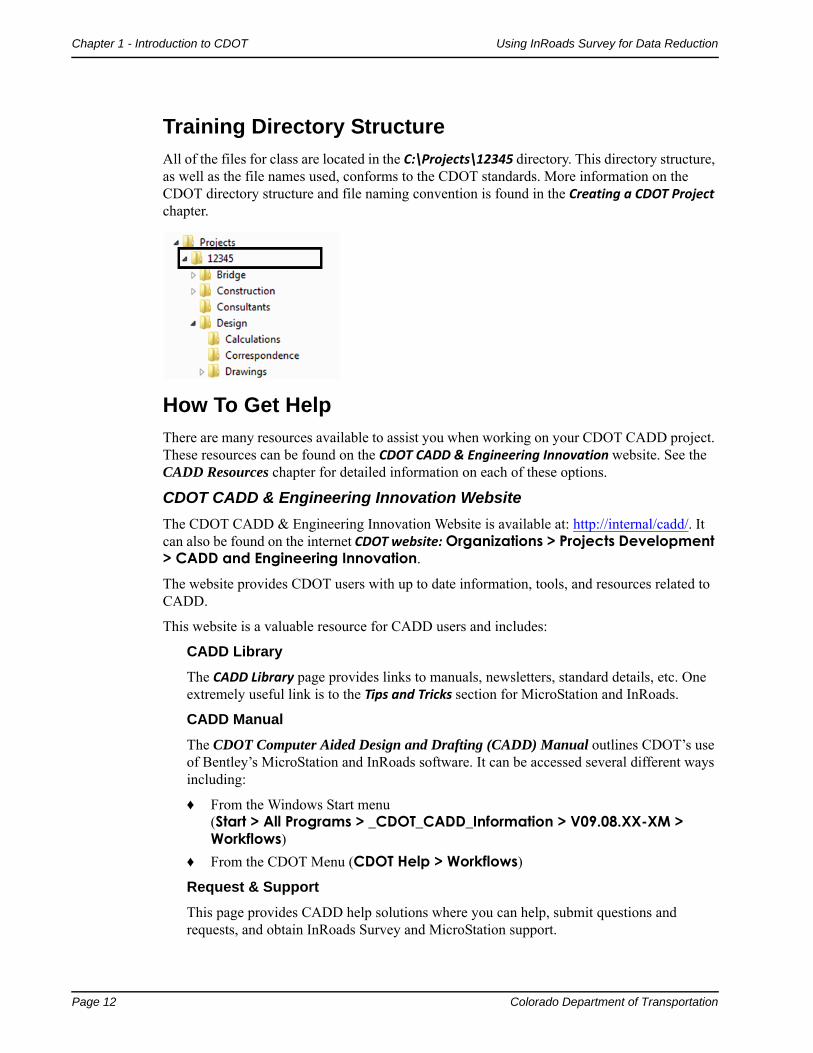
Training Directory Structure
All of the files for class are located in the C:\Projects\12345 directory. This directory structure, as well as the file names used, conforms to the CDOT standards. More information on the CDOT directory structure and file naming convention is found in the Creating a CDOT Project chapter.
How To Get Help
There are many resources available to assist you when working on your CDOT CADD project. These resources can be found on the CDOT CADD & Engineering Innovation website. See the CADD Resources chapter for detailed information on each of these options.
CDOT CADD & Engineering Innovation Website
The CDOT CADD & Engineering Innovation Website is available at: http://internal/cadd/. It can also be found on the internet CDOT website: Organizations > Projects Development > CADD and Engineering Innovation.
The website provides CDOT users with up to date information, tools, and resources related to CADD.
This website is a valuable resource for CADD users and includes:
CADD Library
The CADD Library page provides links to manuals, newsletters, standard details, etc. One extremely useful link is to the Tips and Tricks section for MicroStation and InRoads.
CADD Manual
The CDOT Computer Aided Design and Drafting (CADD) Manual outlines CDOT’s use of Bentley’s MicroStation and InRoads software. It can be accessed several different ways including:
♦ From the Windows Start menu(Start > All Programs > _CDOT_CADD_Information > V09.08.XX-XM > Workflows)
♦ From the CDOT Menu (CDOT Help > Workflows)
Request & Support
This page provides CADD help solutions where you can help, submit questions and requests, and obtain InRoads Survey and MicroStation support.
Colorado Department of Transportation Page 13
Using InRoads Survey for Data Reduction Chapter 1 - Introduction to CDOT
There is also a link to IT Services for hardware support, “how to” instructions, installation, training files, and dual monitor and work space setup.
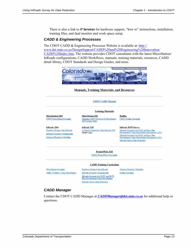
CADD & Engineering Processes
The CDOT CADD & Engineering Processes Website is available at: http://www.dot.state.co.us/DesignSupport/CADD%20and%20Engineering%20Innovation/CADD%20Index.htm. The website provides CDOT consultants with the latest MicroStation/InRoads configurations, CADD Workflows, manuals, training materials, resources, CADD detail library, CDOT Standards and Design Guides, and more.
CADD Manager
Contact the CDOT CADD Manager at [email protected] for additional help or questions.

Page 14 Colorado Department of Transportation
Chapter 1 - Introduction to CDOT Using InRoads Survey for Data Reduction

Colorado Department of Transportation Page 15
Chapter 2 - Getting Started with InRoads Survey
InRoads Survey Interface
Remember, InRoads Survey is running on top of MicroStation. That means the InRoads interface can be moved outside the MicroStation environment to another screen and that the InRoads interface may hide MicroStation dialog boxes.
There are four main parts to the InRoads Survey Interface, the Menu Bar, Workspace Bar, Information Window and Status Bar.
Menu Bar
The Menu Bar pull-down menus are used to access commands, settings, and toolbars.
An arrow > in the pull down will expand to a submenu.
… In the pull down will open a dialog by that name.
The pull-down menus will vary with the application add-ins that are loaded.

Page 16 Colorado Department of Transportation
Chapter 2 - Getting Started with InRoads Survey Using InRoads Survey for Data Reduction
Workspace Bar
The Workspace Bar is used to manage and separate the different file formats of the program.
Right clicking is allowed in the Workspace Bar. The active shortcut menu will vary depending on which Tab is selected.
The Workspace Bar can be undocked as shown here but it is not recommended.
To switch between tabs use the scroll arrows or right click to open a short cut menu.
Information Window
The Information Window varies depending on which Workspace Bar tab is selected.
Right clicking is allowed in the Information Window. The active shortcut menu will vary depending on what feature was selected.
Status Bar
Located in the lower left hand corner of the InRoads Survey Interface, the status bar is used for file processing feedback and tool descriptions.

Colorado Department of Transportation Page 17
Using InRoads Survey for Data Reduction Chapter 2 - Getting Started with InRoads Survey
Project Defaults
Setting project defaults prior to working on any project will save time navigating to directories and will ensure the correct InRoads resources are loaded.
Dialog Items
Configuration Name – Select from the drop down to change the current project directories and resources.
Default Preferences
In this section the user enters specific file names with extension names (types) InRoads will be using. The different file types and their uses are as follows:
♦ Preferences (*.xin) – The main file used to define the symbology and dialog preferences.
♦ *Turnouts (*.txt) – File used to define turnouts.
♦ *Drainage Structures (*.dat) – File used by Storm and Sanitary software.
♦ *Rainfall Data (*.idf) (*.rtc) - File used to calculate rainfall.
♦ *Bridge Sections (*.txt) - File used to define bridge sections.
♦ *Drafting Notes (*.dft) – File used by InRoads drafting tools.
♦ *Pay Items (*.mdb) – File used to calculate pay items and quantities.

Page 18 Colorado Department of Transportation
Chapter 2 - Getting Started with InRoads Survey Using InRoads Survey for Data Reduction
Default Directory Paths.
This section defines directory paths for loading and saving files inside InRoads.
♦ Project Default Directory: - default location for opening, saving, importing, and exporting general files.
♦ Report Directory - default location where report files such as TXT and XML are generated by the report browser.
♦ Projects (*.rwk) – default location of Project’s files.
♦ Surfaces (*.dtm) – default location of Surface files.
♦ Geometry Projects (*.alg) – default location of Geometry Project files.
♦ *Template Libraries (*.itl) – default location of Typical Sections Library files.
♦ *Roadway Design (*.ird) – default location of Roadway Library files.
♦ Survey Data (*.fwd) – default location of Survey Data files.
♦ *Drainage (*.sdb) – default location of Drainage files.
♦ Sheet Style (*.xsl) – default location of Sheet Style files for XML reports.
♦ *Quantity Manager (*.mdb) – default location of Quantity Manager Files.
* Files and directories that do not impact survey applications.
Toolbars
Toolbars can be opened and docked in the InRoads interface. Toolbars in InRoads Survey can be customized to fit the users workflow or personal preference.
From the pull-down menu, select Tools > Customize. The Customize dialog will appear.
Colorado Department of Transportation Page 19
Using InRoads Survey for Data Reduction Chapter 2 - Getting Started with InRoads Survey
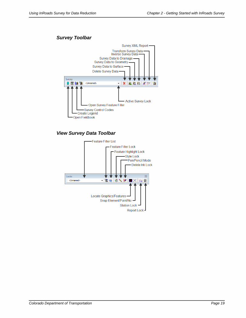
Survey Toolbar
View Survey Data Toolbar

Page 20 Colorado Department of Transportation
Chapter 2 - Getting Started with InRoads Survey Using InRoads Survey for Data Reduction
Locks Toolbar
Docked Toolbars

Colorado Department of Transportation Page 21
Using InRoads Survey for Data Reduction Chapter 2 - Getting Started with InRoads Survey
Survey Options - General Tab
Survey Options dialog controls additional settings required by Survey. The Survey options can be modified by the user and are stored as an FXP file. Some of the main aspects of this dialog are the control of planimetric scale and the Fieldbook Audit Trail file which tracks changes to the fieldbook and features table.
From the pull-down menu, select Tools > Survey Options [General].
Dialog Items
♦ Chord Height: Controls the curve stroking of elements when saved to graphics, surfaces, and alignments. The smaller the value, the greater number of vertices generated.
♦ Point Seed: Seed number used when adding points to the survey fieldbook.
♦ Figure Seed: Seed number used when saving linear planimetrics to a geometry project.
♦ Cell Scale: Scale factor used when writing survey feature Cells to graphics.
♦ Text Scale: Scale factor used when writing survey feature Text to graphics.
♦ Line Scale: Scale factor used when writing survey feature Line Styles to graphics.
♦ Fieldbook Audit Trail File Name: Text file that saves all edits from the fieldbook and feature table. The file will show the edits Before and After.
Page 22 Colorado Department of Transportation
Chapter 2 - Getting Started with InRoads Survey Using InRoads Survey for Data Reduction
♦ File Options○ Resolve Code Errors – If checked, all code errors found while importing will be
taken care of by the Resolve Code Error dialog.
○ Log Code Errors – Will open the Results dialog at the end of the import allowing the errors to be saved to a text file.
○ Save Computed Coordinates – If checked, any computed coordinates will be saved to the fieldbook as individual points.
○ Add/Edit Audit Trail – If checked, displays the Results dialog after each edit is made. Even with it unchecked the file will still keep track of edits.
○ Convert Numeric Codes to Corresponding Alpha Codes on Import - If checked the numeric codes used in the field will be converted to alpha codes in the fieldbook.
♦ View Options○ Automatic Refresh – If checked, will regenerate the displayed graphics after
each edit.
○ Segregate Text by Feature Level – If checked, will save the symbols, point names, codes, notes, errors, and elevations to the same level as the survey feature.
♦ Planimetric Settings○ Use Custom Operations – If checked, all Custom Operations from the Survey
Feature Table will be displayed.
○ Use Symbols – If checked, all symbols from the Survey Feature table will be displayed.
○ Use Cells – If checked, all Cells from the Survey Feature table will be displayed.
○ Include Custom Operations, Symbols and Cells in Single Cell – If checked, all items will be combined into a single cell called NULL.
○ Attach Default Tags – If checked, a default InRoads tag will be defined and attached to the MicroStation graphic when written to a design file.
○ Attach Attribute Tags – If checked, a tag, with attribute information and values will be attached to the MicroStation graphic when written to a design file.
Colorado Department of Transportation Page 23
Using InRoads Survey for Data Reduction Chapter 2 - Getting Started with InRoads Survey
Survey Options - Units Tab
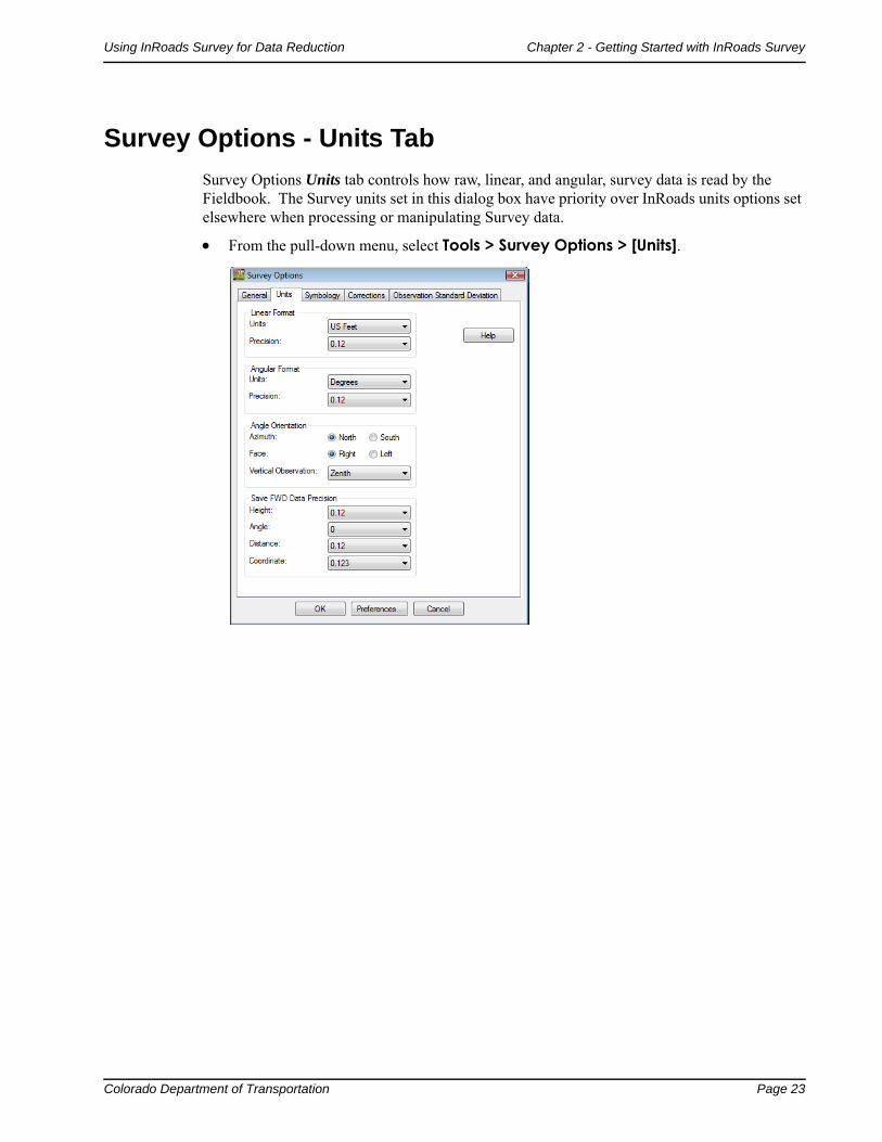
Survey Options Units tab controls how raw, linear, and angular, survey data is read by the Fieldbook. The Survey units set in this dialog box have priority over InRoads units options set elsewhere when processing or manipulating Survey data.
From the pull-down menu, select Tools > Survey Options > [Units].
Page 24 Colorado Department of Transportation
Chapter 2 - Getting Started with InRoads Survey Using InRoads Survey for Data Reduction
Survey Options - Symbology Tab
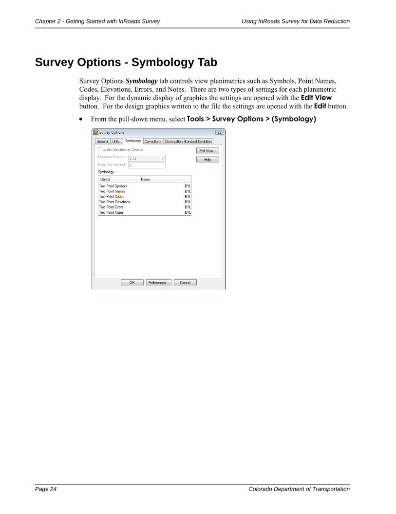
Survey Options Symbology tab controls view planimetrics such as Symbols, Point Names, Codes, Elevations, Errors, and Notes. There are two types of settings for each planimetric display. For the dynamic display of graphics the settings are opened with the Edit View button. For the design graphics written to the file the settings are opened with the Edit button.
From the pull-down menu, select Tools > Survey Options > (Symbology)
Colorado Department of Transportation Page 25
Chapter 3 - Working with InRoads Survey – Overview
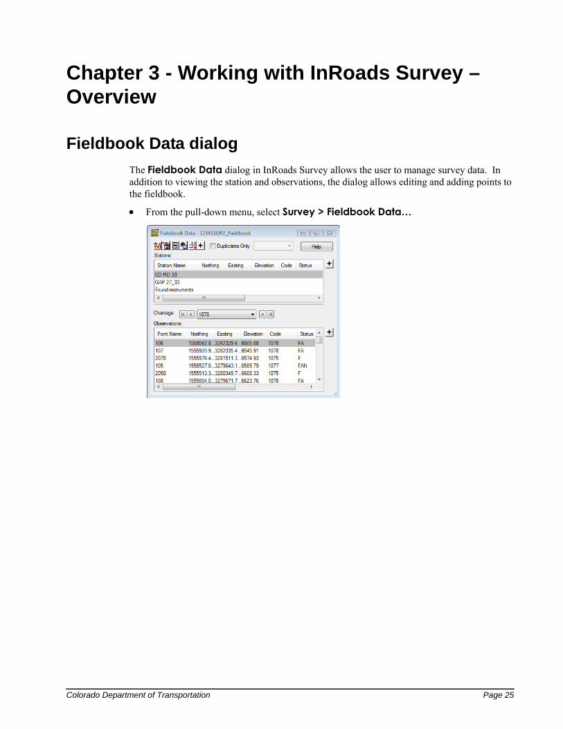
Fieldbook Data dialog
The Fieldbook Data dialog in InRoads Survey allows the user to manage survey data. In addition to viewing the station and observations, the dialog allows editing and adding points to the fieldbook.
From the pull-down menu, select Survey > Fieldbook Data…
Page 26 Colorado Department of Transportation
Chapter 3 - Working with InRoads Survey – Overview Using InRoads Survey for Data Reduction
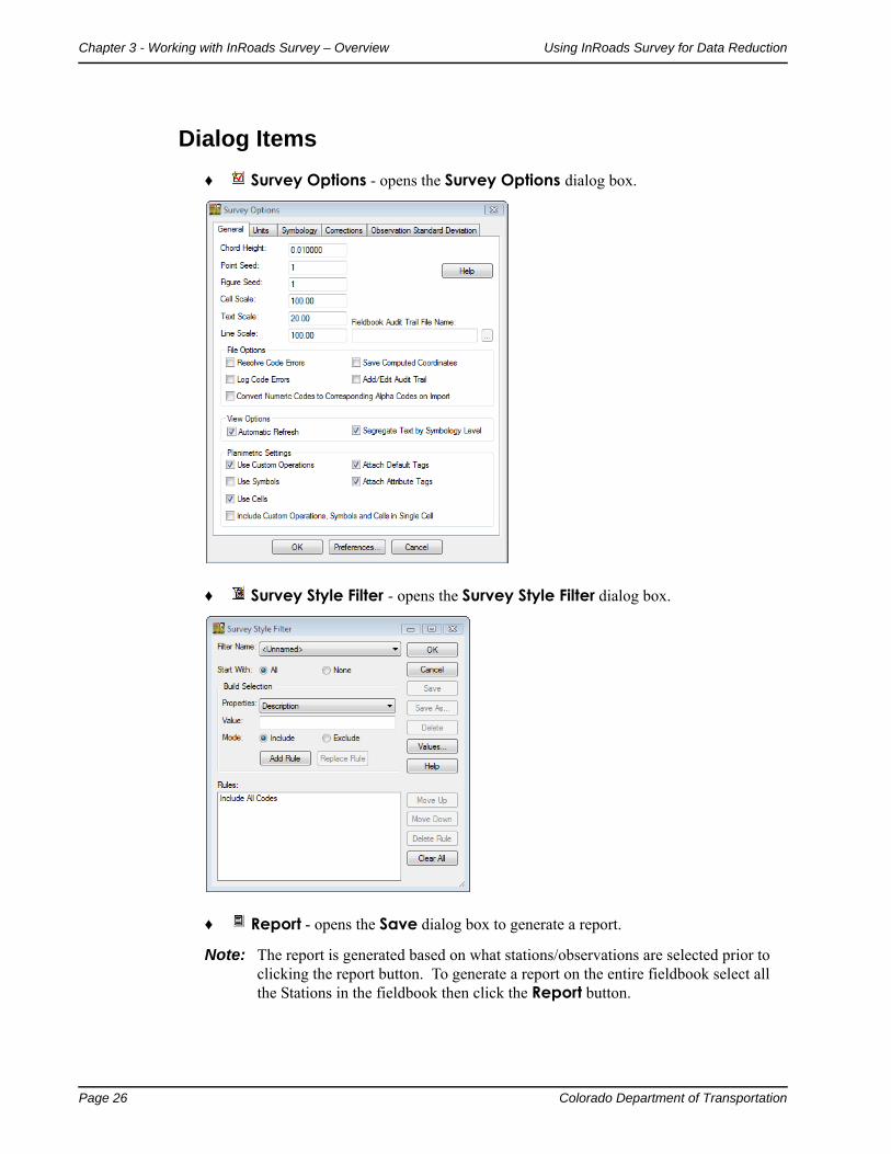
Dialog Items
♦ Survey Options - opens the Survey Options dialog box.
♦ Survey Style Filter - opens the Survey Style Filter dialog box.
♦ Report - opens the Save dialog box to generate a report.
Note: The report is generated based on what stations/observations are selected prior to clicking the report button. To generate a report on the entire fieldbook select all the Stations in the fieldbook then click the Report button.

Colorado Department of Transportation Page 27
Using InRoads Survey for Data Reduction Chapter 3 - Working with InRoads Survey – Overview
♦ Find/Replace Codes - opens the Point Code Find and Replace dialog box.
♦ Select Figure – will only locate the nearest planimetric feature or chainage. The fieldbook will highlight the start of the chainage.
♦ Insert Parallel Point - will add an additional point to a chain based on an existing reference chain.
♦ Duplicates – filters only duplicate points found in the Stations or Observations. To view duplicate points select it from the drop down box.

Page 28 Colorado Department of Transportation
Chapter 3 - Working with InRoads Survey – Overview Using InRoads Survey for Data Reduction
Duplicate Points General Rules:
Rule # 1
If a Point Name is duplicated in a Station Setup then the two points are averaged.
Station 764
Observation 2000
Observation 2000
Observation 2001
Observation 2002
Rule #2
If a Point Name is duplicated in two different Station Setups the points are not averaged and each point is used.
Station 764
Observation 2000
Observation 2001
Observation 2002
Station 766
Observation 2000
Observation 3001
Observation 3002
Note: For more information on how duplicate points are handled in InRoads Survey
select the Help button.
Colorado Department of Transportation Page 29
Using InRoads Survey for Data Reduction Chapter 3 - Working with InRoads Survey – Overview
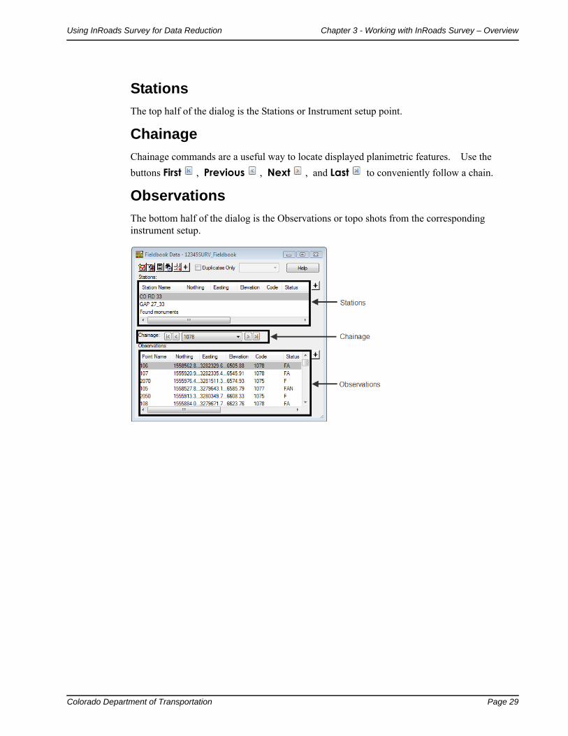
Stations
The top half of the dialog is the Stations or Instrument setup point.
Chainage
Chainage commands are a useful way to locate displayed planimetric features. Use the
buttons First , Previous , Next , and Last to conveniently follow a chain.
Observations
The bottom half of the dialog is the Observations or topo shots from the corresponding instrument setup.

Page 30 Colorado Department of Transportation
Chapter 3 - Working with InRoads Survey – Overview Using InRoads Survey for Data Reduction

Colorado Department of Transportation Page 31
Chapter 4 - Exporting the Fieldbook – Overview
Write Survey Data to Graphics dialog
Writing Survey data to graphics creates the MicroStation design file (DGN) basemap. Once the file has been saved to a MicroStation design file there no longer is a link between the InRoads Survey fieldbook and MicroStation graphics. If there are changes that need to be made to the graphics, modify the InRoads Survey fieldbook and then re-export the graphics.
Dialog Items:
Planimetrics – if checked Planimetrics such as lines, chorded arcs, and cells will be saved to the design file
Symbols – if checked a tic mark representing the location of the shot will be saved to the design file.
Names – if checked the point name of the shot will be saved to the design file.
Codes - if checked the point feature code of the shot will be saved to the design file.
Elevations – if checked the point elevation of the shot will be saved to the design file.
Errors – if checked any errors in the fieldbook will be saved to the design file.
Notes – if checked any notes in the fieldbook will be saved to the design file.
Network – if checked any traverse legs will be saved to the design file.
Apply – will save the checked items to the design file
Filter- will allow the user to include or exclude any feature codes by a set of rules. Only the feature codes that pass through the filter will be saved to the design file.
Note: The symbology for Symbols, Points, Elevations, Notes, Errors, and Codes is controlled in the Survey Options dialog.
Planarize
Elevation – if checked all points will place at a defined elevation.

Page 32 Colorado Department of Transportation
Chapter 4 - Exporting the Fieldbook – Overview Using InRoads Survey for Data Reduction
Curve Stroking Modes
Curves generated from Survey are chorded arcs based on the Chord Height distance in the Survey Options dialog. MicroStation will generate a number of small line segments to represent the arc. There are three settings for generating arcs in 2D and 3D graphics.
Horizontal and VerticalThe curve is created by multipoint splines in the x, y, and z directions. In extreme variations in elevations unwanted sag or crest of a curve may occur.
Horizontal OnlyThe curve is created by multipoint splines only in the x and y directions. The elevations or z values of the points are interpolated linearly between points.
Do Not StrokeThe curve is not created. It will be represented as linear elements between points.
Colorado Department of Transportation Page 33
Using InRoads Survey for Data Reduction Chapter 4 - Exporting the Fieldbook – Overview
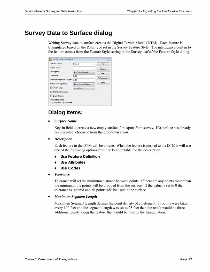
Survey Data to Surface dialog
Writing Survey data to surface creates the Digital Terrain Model (DTM). Each feature is triangulated based on the Point type set in the Survey Feature Style. The intelligence built in to the feature comes from the Feature Style setting in the Survey leaf of the Feature Style dialog.
Dialog Items:
Surface Name
Key-in field to create a new empty surface for export from survey. If a surface has already been created, choose it from the dropdown arrow.
Description
Each feature in the DTM will be unique. When the feature is pushed to the DTM it will use one of the following options from the Feature table for the description.
♦ Use Feature Definition♦ Use Attributes♦ Use Codes
Tolerance
Tolerance will set the minimum distance between points. If there are any points closer than the minimum, the points will be dropped from the surface. If the value is set to 0 then tolerance is ignored and all points will be used in the surface.
Maximum Segment Length
Maximum Segment Length defines the point density of an element. If points were taken every 100 feet and the segment length was set to 25 feet then the result would be three additional points along the feature that would be used in the triangulation.
Page 34 Colorado Department of Transportation
Chapter 4 - Exporting the Fieldbook – Overview Using InRoads Survey for Data Reduction
Curve Stroking Mode
Curve Stroking Mode defines a curve horizontally and vertically. Curves in InRoads are defined by short line segments from the Survey Options dialog Chord Height.
Horizontal and Vertical
The curve is created by multipoint splines in the x, y, and z directions. If extreme variations in elevations exist, unwanted sag or crest of a curve may occur.
Horizontal Only
The curve is created by multipoint splines only in the x and y directions. The elevations or z values of the points are interpolated linearly between points.
Do Not Stroke
The curve is not created. It will be represented as linear elements between points.
Always Use:
Defines what each feature style name will be in the surface. CDOT has defined a Style for each survey feature that corresponds to an InRoads Feature Style. By default if it is unchecked the feature style will be assigned in the following order.
Style – Preference Style name defined in the feature table.
Alpha Code Numeric Code
Triangulate Surface
If checked the Triangulate Surface dialog will appear after the surface has been exported.

Colorado Department of Transportation Page 35
Using InRoads Survey for Data Reduction Chapter 4 - Exporting the Fieldbook – Overview
Triangulate Surface dialog
This dialog will appear when triangulate surface in the Survey to Surface dialog is checked. Exporting Survey data to Surface without triangulating it will result with the data being pushed to the surface, but the triangle network will not exist yet.
Dialog items:
Surface – drop down box shows the active surface by default, other surfaces selectable from the drop down.
Extended Data Checks - checks DTM integrity (during triangulation) as to crossing breaklines and miss-matched elevations.
Maximum Length - maximum length of any one triangle segment (leg) can span during the triangulation process. If set to 0, triangle legs can extend to any length. Used to constrain triangulation to prevent unnecessary ‘surface’ data.
♦ Target button – define a Maximum Length distance by picking two points in a MicroStation view.
Load Tagged Graphics – scans the design file for any InRoads tagged data and loads the elements into the surface.
Delete Surface Contents – empties the surface prior to adding any tagged elements.
Results – readout of triangulation outcome.
More – opens the Surface Properties dialog.
Page 36 Colorado Department of Transportation
Chapter 4 - Exporting the Fieldbook – Overview Using InRoads Survey for Data Reduction
Multiple Feature coding and the DTM
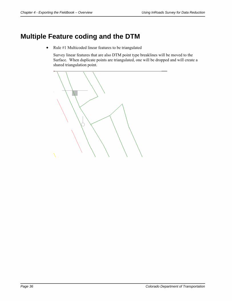
Rule #1 Multicoded linear features to be triangulated
Survey linear features that are also DTM point type breaklines will be moved to the Surface. When duplicate points are triangulated, one will be dropped and will create a shared triangulation point.

Colorado Department of Transportation Page 37
Using InRoads Survey for Data Reduction Chapter 4 - Exporting the Fieldbook – Overview
Rule #2 Multicoded linear features with random points to be triangulated
Survey linear features and random points will be moved to the Surface. However, when duplicate points are triangulated the breakline will override and the random point will be dropped entirely from the surface.
The only way to keep this from happening is to exclude the random point from triangulation with a control code “X”. This will allow the feature to remain part of the surface.
Rule #3 Multicoded linear features excluded from triangulation with random points to be triangulated
Survey linear features that are excluded from triangulation and random point types will be moved to the Surface. When duplicate points are triangulated the linear feature will remain and the random point will be used for triangulation.
Page 38 Colorado Department of Transportation
Chapter 4 - Exporting the Fieldbook – Overview Using InRoads Survey for Data Reduction
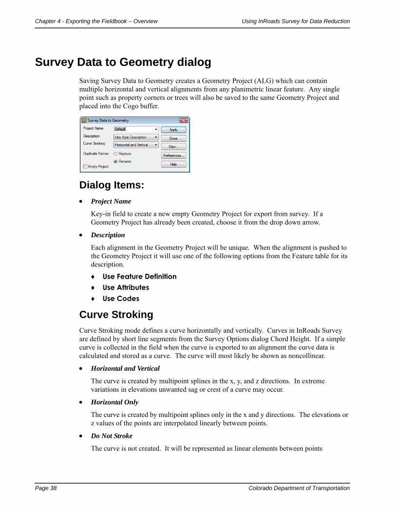
Survey Data to Geometry dialog
Saving Survey Data to Geometry creates a Geometry Project (ALG) which can contain multiple horizontal and vertical alignments from any planimetric linear feature. Any single point such as property corners or trees will also be saved to the same Geometry Project and placed into the Cogo buffer.
Dialog Items:
Project Name
Key-in field to create a new empty Geometry Project for export from survey. If a Geometry Project has already been created, choose it from the drop down arrow.
Description
Each alignment in the Geometry Project will be unique. When the alignment is pushed to the Geometry Project it will use one of the following options from the Feature table for its description.
♦ Use Feature Definition♦ Use Attributes♦ Use Codes
Curve Stroking
Curve Stroking mode defines a curve horizontally and vertically. Curves in InRoads Survey are defined by short line segments from the Survey Options dialog Chord Height. If a simple curve is collected in the field when the curve is exported to an alignment the curve data is calculated and stored as a curve. The curve will most likely be shown as noncollinear.
Horizontal and Vertical
The curve is created by multipoint splines in the x, y, and z directions. In extreme variations in elevations unwanted sag or crest of a curve may occur.
Horizontal Only
The curve is created by multipoint splines only in the x and y directions. The elevations or z values of the points are interpolated linearly between points.
Do Not Stroke
The curve is not created. It will be represented as linear elements between points
Colorado Department of Transportation Page 39
Chapter 5 - Importing Data
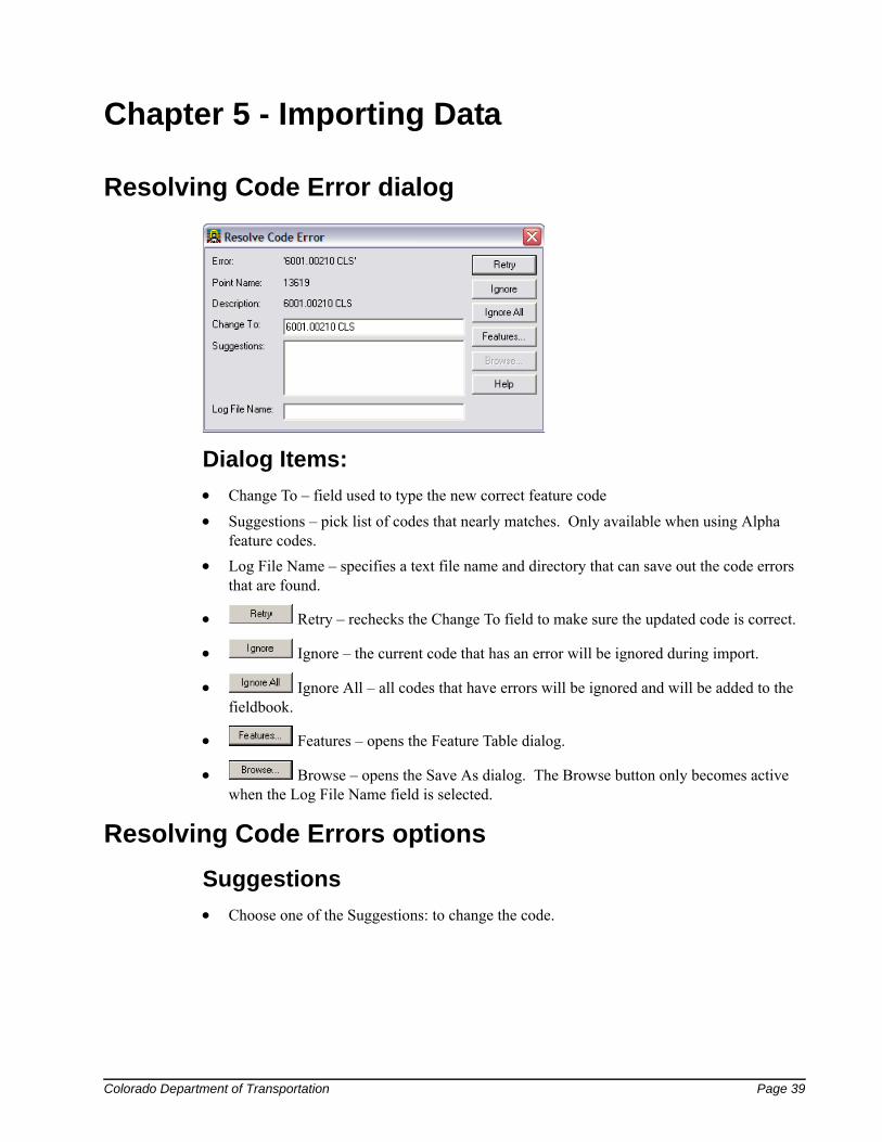
Resolving Code Error dialog
Dialog Items:
Change To – field used to type the new correct feature code
Suggestions – pick list of codes that nearly matches. Only available when using Alpha feature codes.
Log File Name – specifies a text file name and directory that can save out the code errors that are found.
Retry – rechecks the Change To field to make sure the updated code is correct.
Ignore – the current code that has an error will be ignored during import.
Ignore All – all codes that have errors will be ignored and will be added to the fieldbook.
Features – opens the Feature Table dialog.
Browse – opens the Save As dialog. The Browse button only becomes active when the Log File Name field is selected.
Resolving Code Errors options
Suggestions
Choose one of the Suggestions: to change the code.
Page 40 Colorado Department of Transportation
Chapter 5 - Importing Data Using InRoads Survey for Data Reduction
<D> the Retry button. The code will be corrected and processed. The dialog will then move on to the next code error. Continue correcting code errors until complete.
Manually Correct
Key in the correct code in the Change To: field.
<D> the Retry button. The code will be corrected and processed. The dialog will then move on to the next code error. Continue correcting code errors until complete.
Ignore
When unsure of the correct code <D> the Ignore button.
The code will be ignored. The dialog will then move on to the next code error. Continue ignoring code errors until complete.

Colorado Department of Transportation Page 41
Using InRoads Survey for Data Reduction Chapter 5 - Importing Data
The Results dialog will appear showing what codes still have errors. This report can be saved as a text file to the project directory or dismissed.
Ignore All
When unsure of all the correct codes <D> the Ignore All button.
All codes will be ignored. The Resolve Code Error dialog will then close.
The Results dialog will appear showing what codes still have errors. This report can be saved as a text file to the project directory or dismissed.
Saving Error Results
Page 42 Colorado Department of Transportation
Chapter 5 - Importing Data Using InRoads Survey for Data Reduction
Dialog items:
♦ Save As – opens the Save As dialog. This will create a text file that can be opened in Notepad.
♦ Append – opens the Append dialog allowing the user to add additional errors to the end of an existing file.
♦ Display – will write the text to graphics. The text will be displayed using the active text style.
♦ Print – opens the Print Setup dialog. The file will be printed and will not save the file to disk.
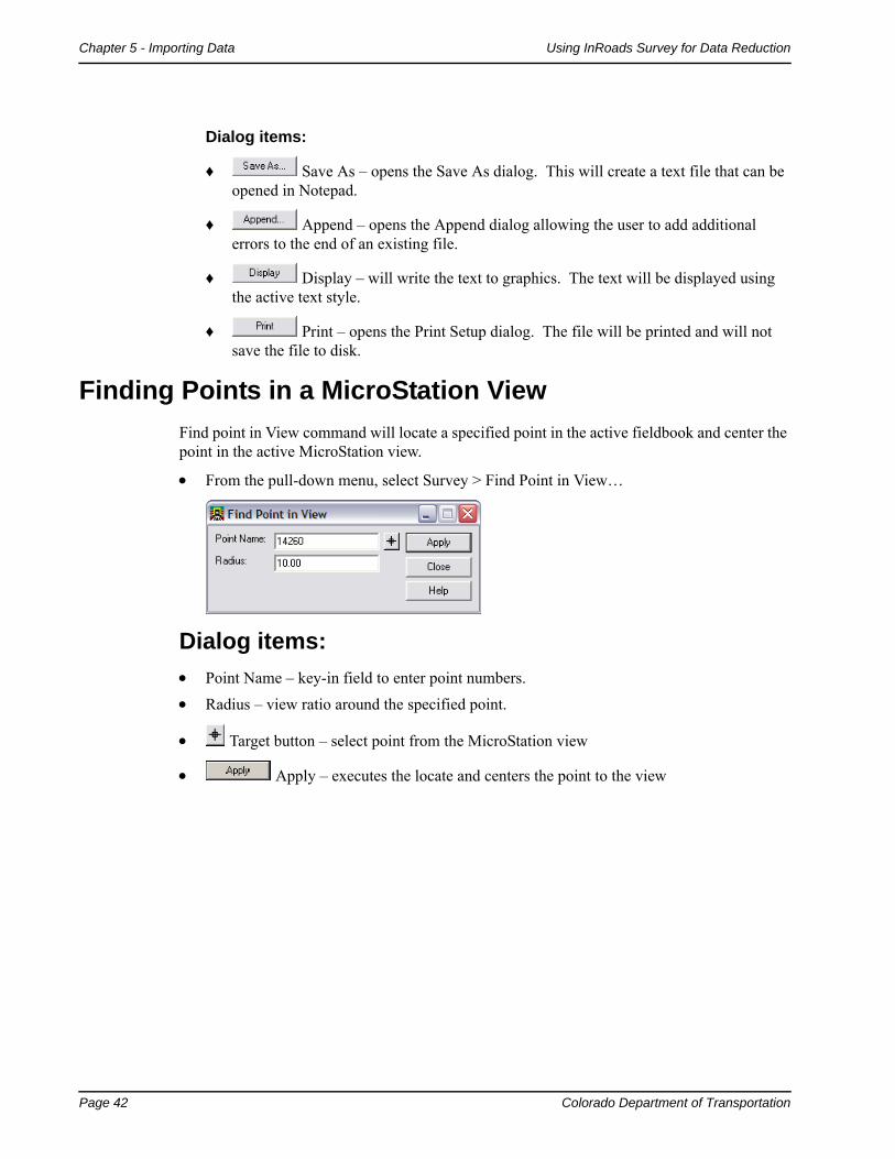
Finding Points in a MicroStation View
Find point in View command will locate a specified point in the active fieldbook and center the point in the active MicroStation view.
From the pull-down menu, select Survey > Find Point in View…
Dialog items:
Point Name – key-in field to enter point numbers.
Radius – view ratio around the specified point.
Target button – select point from the MicroStation view
Apply – executes the locate and centers the point to the view

Colorado Department of Transportation Page 43
Using InRoads Survey for Data Reduction Chapter 6 - Feature Codes and Control Codes
Chapter 6 - Feature Codes and Control Codes
The Feature Styles defined for Survey control how a feature is displayed in the design file, written to a DTM, or exported to Geometry. There are two main types of graphic displays: lines and cells. Additionally, there are a few codes that place text through the use of Custom Operations. The Styles definition also controls, through the association with a Named Symbology, the symbology for the graphics such as level, color, style, and weight.
Extensive effort has been made to ensure the correct symbology is defined in the Feature Style. Changes to Feature Styles will be made only by the CDOT CADD Manager. Any suggested changes should be submitted to the CADD Manager as all of CDOT’s InRoads configuration is stored in the standard delivered CDOT_Civil.xin file.
Style Manager dialog
The Style Manager dialog controls how each surveyed feature is displayed graphically. Each feature can be displayed as Lines, Cells, Text, or Symbols. The feature definitions have been standardized by CDOT and should only be modified by the CADD manager.
From the pull-down menu, select Tools > Style Manager…
Page 44 Colorado Department of Transportation
Chapter 6 - Feature Codes and Control Codes Using InRoads Survey for Data Reduction
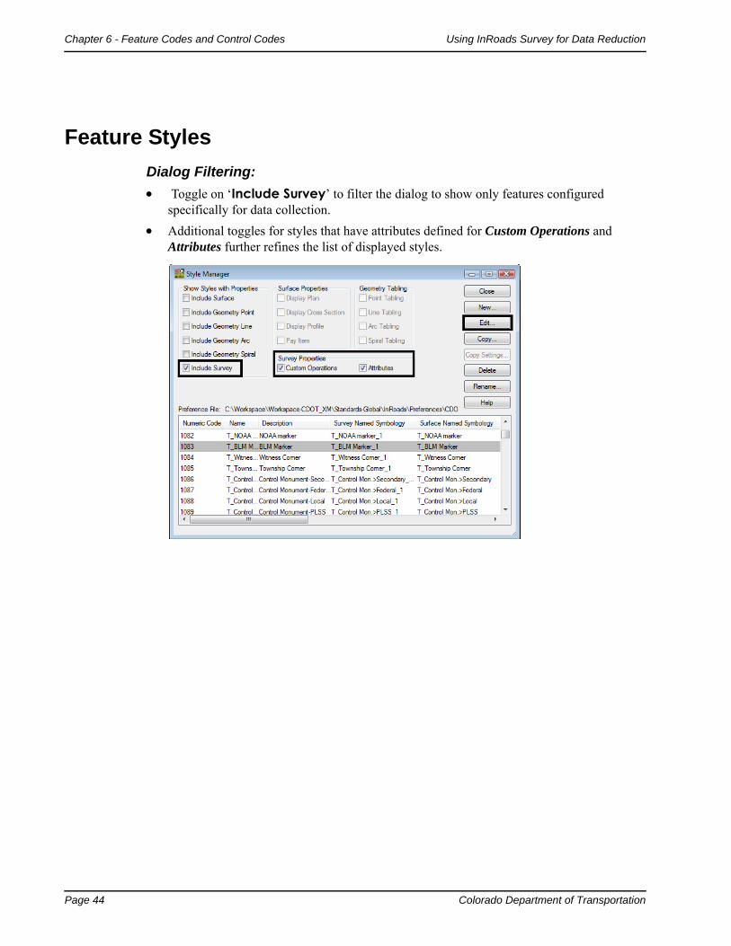
Feature Styles
Dialog Filtering:
Toggle on ‘Include Survey’ to filter the dialog to show only features configured specifically for data collection.
Additional toggles for styles that have attributes defined for Custom Operations and Attributes further refines the list of displayed styles.
Colorado Department of Transportation Page 45
Using InRoads Survey for Data Reduction Chapter 6 - Feature Codes and Control Codes
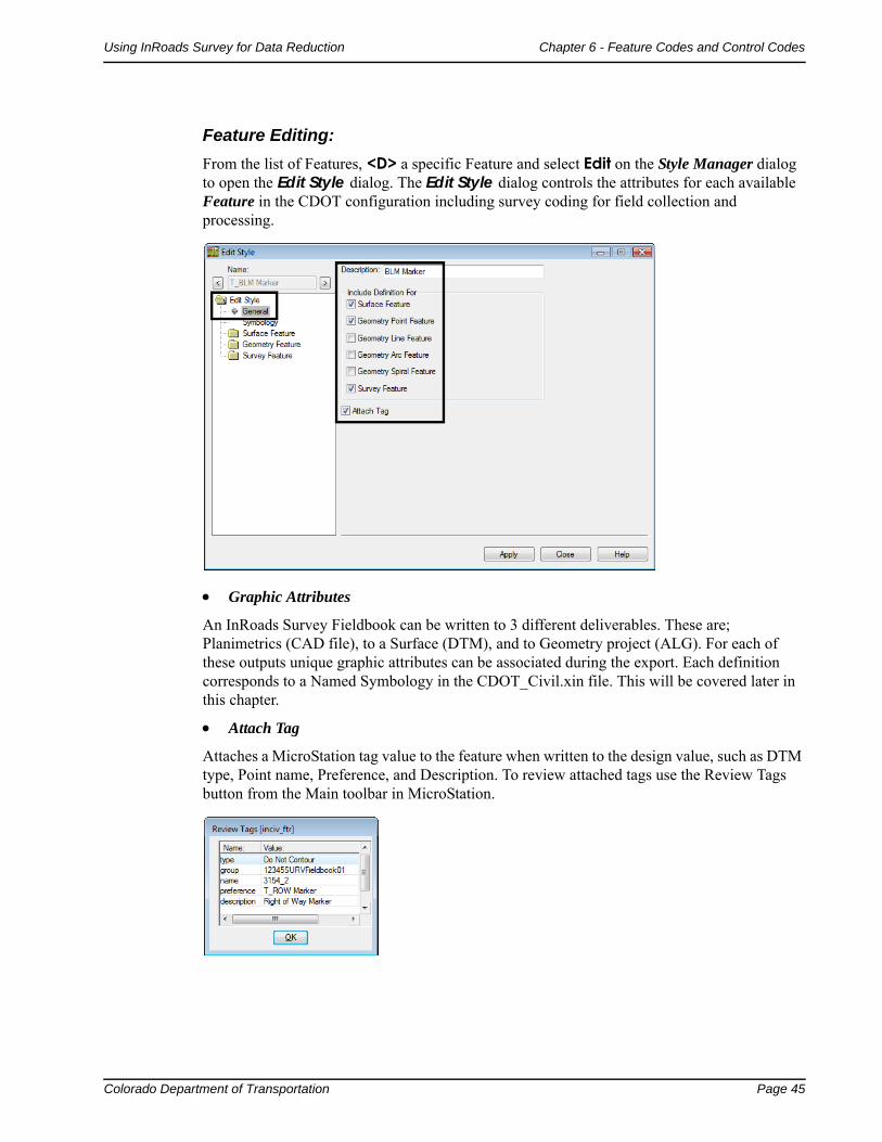
Feature Editing:
From the list of Features, <D> a specific Feature and select Edit on the Style Manager dialog to open the Edit Style dialog. The Edit Style dialog controls the attributes for each available Feature in the CDOT configuration including survey coding for field collection and processing.
Graphic Attributes
An InRoads Survey Fieldbook can be written to 3 different deliverables. These are; Planimetrics (CAD file), to a Surface (DTM), and to Geometry project (ALG). For each of these outputs unique graphic attributes can be associated during the export. Each definition corresponds to a Named Symbology in the CDOT_Civil.xin file. This will be covered later in this chapter.
Attach Tag
Attaches a MicroStation tag value to the feature when written to the design value, such as DTM type, Point name, Preference, and Description. To review attached tags use the Review Tags button from the Main toolbar in MicroStation.
Page 46 Colorado Department of Transportation
Chapter 6 - Feature Codes and Control Codes Using InRoads Survey for Data Reduction
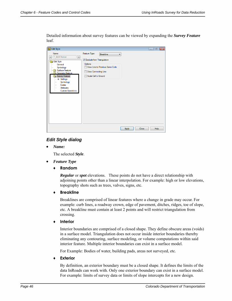
Detailed information about survey features can be viewed by expanding the Survey Feature leaf.
Edit Style dialog
Name:
The selected Style.
Feature Type
♦ RandomRegular or spot elevations. These points do not have a direct relationship with adjoining points other than a linear interpolation. For example: high or low elevations, topography shots such as trees, valves, signs, etc.
♦ BreaklineBreaklines are comprised of linear features where a change in grade may occur. For example: curb lines, a roadway crown, edge of pavement, ditches, ridges, toe of slope, etc. A breakline must contain at least 2 points and will restrict triangulation from crossing.
♦ InteriorInterior boundaries are comprised of a closed shape. They define obscure areas (voids) in a surface model. Triangulation does not occur inside interior boundaries thereby eliminating any contouring, surface modeling, or volume computations within said interior feature. Multiple interior boundaries can exist in a surface model.
For Example: Bodies of water, building pads, areas not surveyed, etc.
♦ ExteriorBy definition, an exterior boundary must be a closed shape. It defines the limits of the data InRoads can work with. Only one exterior boundary can exist in a surface model. For example: limits of survey data or limits of slope intercepts for a new design.
Colorado Department of Transportation Page 47
Using InRoads Survey for Data Reduction Chapter 6 - Feature Codes and Control Codes
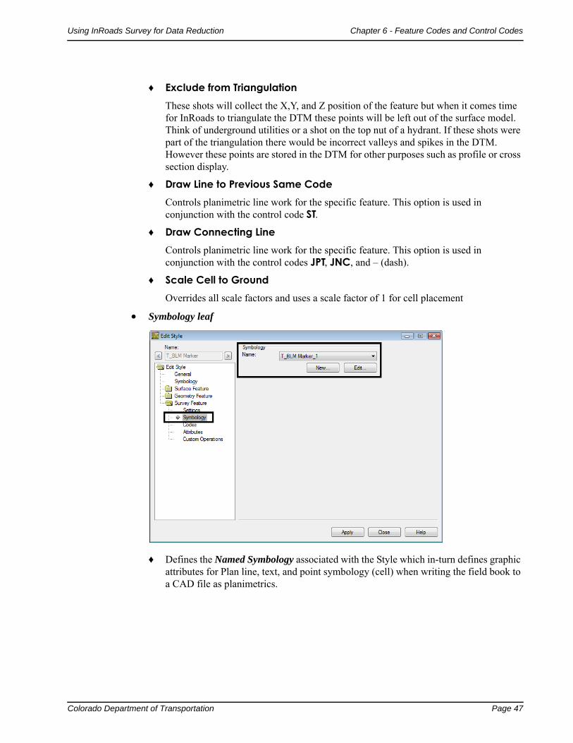
♦ Exclude from TriangulationThese shots will collect the X,Y, and Z position of the feature but when it comes time for InRoads to triangulate the DTM these points will be left out of the surface model. Think of underground utilities or a shot on the top nut of a hydrant. If these shots were part of the triangulation there would be incorrect valleys and spikes in the DTM. However these points are stored in the DTM for other purposes such as profile or cross section display.
♦ Draw Line to Previous Same CodeControls planimetric line work for the specific feature. This option is used in conjunction with the control code ST.
♦ Draw Connecting LineControls planimetric line work for the specific feature. This option is used in conjunction with the control codes JPT, JNC, and – (dash).
♦ Scale Cell to GroundOverrides all scale factors and uses a scale factor of 1 for cell placement
Symbology leaf
♦ Defines the Named Symbology associated with the Style which in-turn defines graphic attributes for Plan line, text, and point symbology (cell) when writing the field book to a CAD file as planimetrics.

Page 48 Colorado Department of Transportation
Chapter 6 - Feature Codes and Control Codes Using InRoads Survey for Data Reduction
Codes leaf
♦ Alpha CodeAlpha codes are used as an additional way to collect the survey data in the field. Alpha feature codes are not to be used as part of the CDOT collection process.
♦ Numeric CodeAssociates a unique numeric code with the Feature Style.

Colorado Department of Transportation Page 49
Using InRoads Survey for Data Reduction Chapter 6 - Feature Codes and Control Codes
Attributes leaf
♦ Attributes are used to help further define or control survey features collected in the field. Attributes can be collected as numeric or alpha data. As an example, additional information such as size, flow, and silt levels in a culvert pipe can be added to a single shot taken in the field. Any survey shots taken in the field without attributes defined will display an ‘A’ in the status column of the electronic fieldbook. If a value is defined, a ‘V’ will display in the fieldbook.
Custom Operations leaf
♦ Custom operations can be thought of as a script file or a list of commands that are run on a certain survey feature. It can be used to control graphic types, symbology, text, placement, and also perform math functions. MicroStation and InRoads key-ins are used to enter commands strings. To view examples of custom operations <D> the Help button.
Page 50 Colorado Department of Transportation
Chapter 6 - Feature Codes and Control Codes Using InRoads Survey for Data Reduction
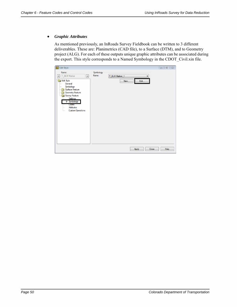
Graphic Attributes
As mentioned previously, an InRoads Survey Fieldbook can be written to 3 different deliverables. These are: Planimetrics (CAD file), to a Surface (DTM), and to Geometry project (ALG). For each of these outputs unique graphic attributes can be associated during the export. This style corresponds to a Named Symbology in the CDOT_Civil.xin file.

Colorado Department of Transportation Page 51
Using InRoads Survey for Data Reduction Chapter 6 - Feature Codes and Control Codes
Edit Style dialog
Selecting the Edit button in the symbology portion of the Edit Style dialog opens the identified Named Symbology.
Identifying a specific attribute and selecting Edit opens additional detailed information on how the graphics will be written as linework, text, or cell to the CAD file.
Line Symbology
Controls the Level, Color, Style, and weight of lines or arcs for individual features written to graphics.
Page 52 Colorado Department of Transportation
Chapter 6 - Feature Codes and Control Codes Using InRoads Survey for Data Reduction
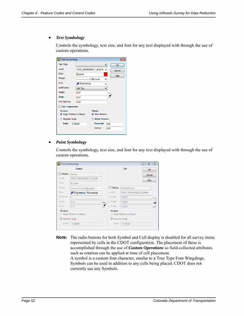
Text Symbology
Controls the symbology, text size, and font for any text displayed with through the use of custom operations.
Point Symbology
Controls the symbology, text size, and font for any text displayed with through the use of custom operations.
Note: The radio buttons for both Symbol and Cell display is disabled for all survey items represented by cells in the CDOT configuration. The placement of these is accomplished through the use of Custom Operations so field-collected attributes such as rotation can be applied at time of cell placement. A symbol is a custom font character, similar to a True Type Font Wingdings. Symbols can be used in addition to any cells being placed. CDOT does not currently use any Symbols.
Colorado Department of Transportation Page 53
Using InRoads Survey for Data Reduction Chapter 6 - Feature Codes and Control Codes
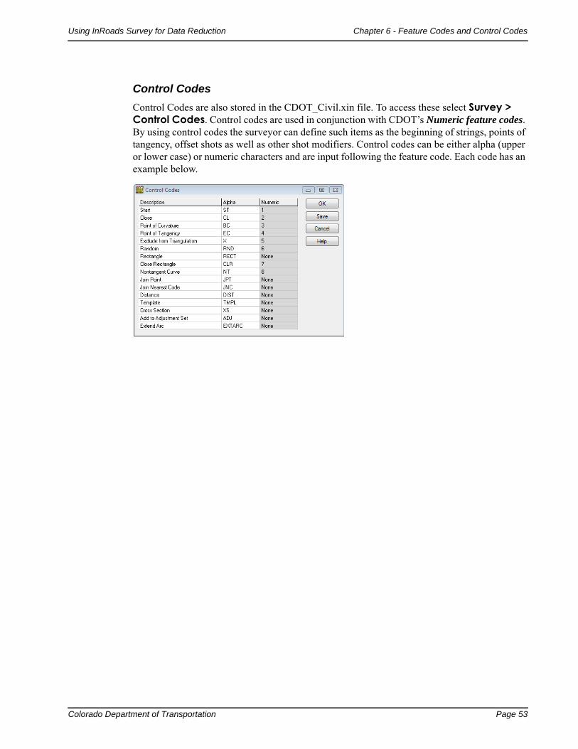
Control Codes
Control Codes are also stored in the CDOT_Civil.xin file. To access these select Survey > Control Codes. Control codes are used in conjunction with CDOT’s Numeric feature codes. By using control codes the surveyor can define such items as the beginning of strings, points of tangency, offset shots as well as other shot modifiers. Control codes can be either alpha (upper or lower case) or numeric characters and are input following the feature code. Each code has an example below.
Page 54 Colorado Department of Transportation
Chapter 6 - Feature Codes and Control Codes Using InRoads Survey for Data Reduction
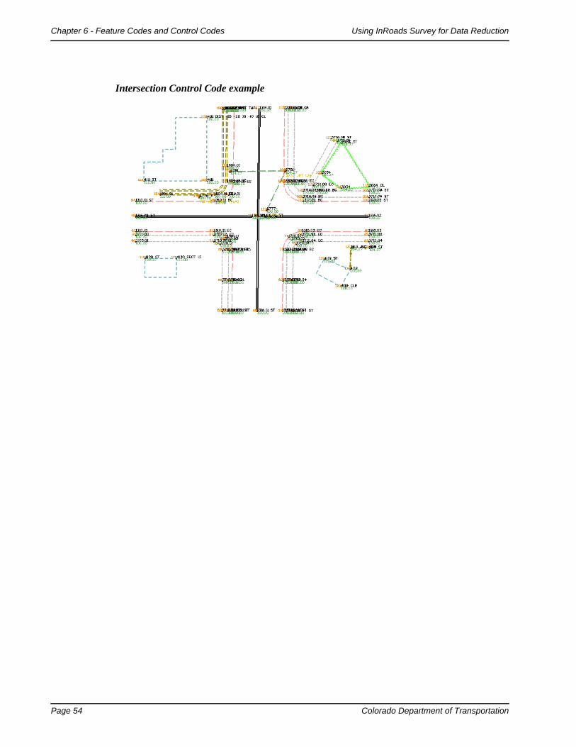
Intersection Control Code example

Colorado Department of Transportation Page 55
Using InRoads Survey for Data Reduction Chapter 6 - Feature Codes and Control Codes
Start
Alpha ST | Numeric 1
Control Code Start begins planimetric lines; there is no code to end a string. InRoads Survey will continue a string until no further data is collected using that code and string identifier. If the same code and string identifier is entered using the ST control code, the previous string will be terminated and a new string begun. See the example below for feature code 1316.02 (feature.string# ST)
Note: It is not mandatory that string identifiers be used. This is only necessary if you wish to collect data using identical feature codes and need to develop multiple strings simultaneously. Examples of this may be when surveying in a crisscross fashion and wish to collect multiple 1310 (edge of oil) strings. If surveying in a linear fashion (collecting the entire length of the physical feature) a code such as 1310 st could be used and reused when moving from one pavement edge to another
Page 56 Colorado Department of Transportation
Chapter 6 - Feature Codes and Control Codes Using InRoads Survey for Data Reduction
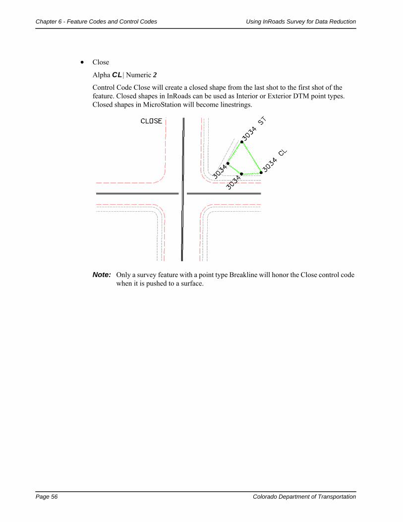
Close
Alpha CL | Numeric 2
Control Code Close will create a closed shape from the last shot to the first shot of the feature. Closed shapes in InRoads can be used as Interior or Exterior DTM point types. Closed shapes in MicroStation will become linestrings.
Note: Only a survey feature with a point type Breakline will honor the Close control code when it is pushed to a surface.

Colorado Department of Transportation Page 57
Using InRoads Survey for Data Reduction Chapter 6 - Feature Codes and Control Codes
Point of Curvature
Alpha BC | Numeric 3
Control code Point of Curvature identifies the beginning of the curve. The incoming tangent of the curve controls the degree of curve.
Point of Tangency
Alpha EC | Numeric 4
Control code Point of Tangency identifies the end of the curve. The outgoing tangent of the curve controls the degree of curve
Note: If a single point on arc is taken then the tangent lines are ignored and the curve is generated by the three points PC, POC, and PT.
Note: If more than one point is taken on the arc then the tangent lines are used when calculating the PC and PT of the curve. CDOT has standardized using the control code NT non-tangent to follow all BC and EC shots. Coding with NT will not add calculated PC’s and PT’s to the linear features. The PC’s and PT’s will be observed points as in the field.
Page 58 Colorado Department of Transportation
Chapter 6 - Feature Codes and Control Codes Using InRoads Survey for Data Reduction
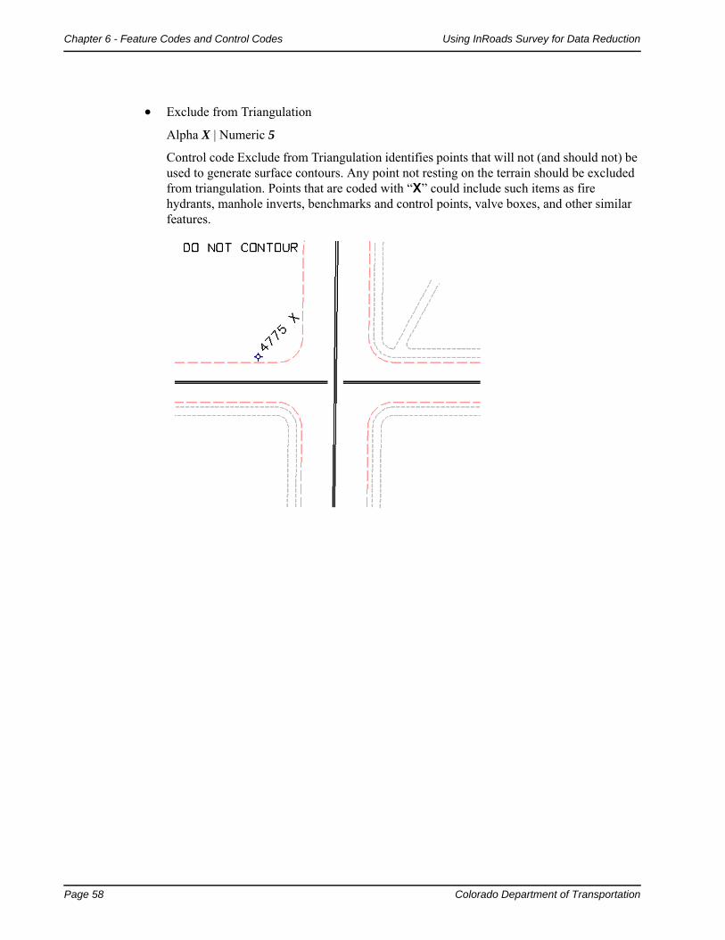
Exclude from Triangulation
Alpha X | Numeric 5
Control code Exclude from Triangulation identifies points that will not (and should not) be used to generate surface contours. Any point not resting on the terrain should be excluded from triangulation. Points that are coded with “X” could include such items as fire hydrants, manhole inverts, benchmarks and control points, valve boxes, and other similar features.

Colorado Department of Transportation Page 59
Using InRoads Survey for Data Reduction Chapter 6 - Feature Codes and Control Codes
Random
Alpha RND | Numeric 6
Control code Random overwrites DTM point types set in the Survey Feature table. For example Breaklines become Random types and Do Not Contour point types become Random points Excluded from triangulation.
Rectangle
Alpha RECT | Numeric None
Control code Rectangle will draw a rectangle based on two points shot in the field and a measured distance. The two points collected in the filed define the direction of the baseline and the measured distance defines the width. The previous two points collected in the filed define the direction of the baseline. To turn left of the baseline use a negative number (-15); to turn right of the baseline use a positive number (15). Each added point using the Rectangle command will be considered a derived point in Survey.
Note: Only a survey feature with a point type Breakline will honor the Rectangle control code when it is pushed to a surface.

Page 60 Colorado Department of Transportation
Chapter 6 - Feature Codes and Control Codes Using InRoads Survey for Data Reduction
Close Rectangle
Alpha CLR | Numeric 7
Control code Close Rectangle will draw a trapezoid based on three points shot in the field. The last two points become the baseline and the fourth point generated will be 90 degrees to the baseline.
Note: Only a survey feature with a point type Breakline will honor the Close Rectangle control code when it is pushed to a surface.
Colorado Department of Transportation Page 61
Using InRoads Survey for Data Reduction Chapter 6 - Feature Codes and Control Codes
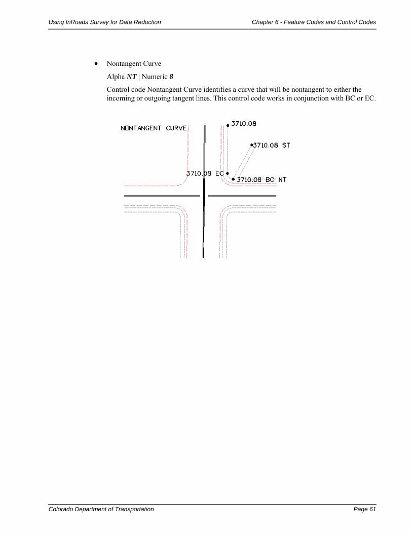
Nontangent Curve
Alpha NT | Numeric 8
Control code Nontangent Curve identifies a curve that will be nontangent to either the incoming or outgoing tangent lines. This control code works in conjunction with BC or EC.

Page 62 Colorado Department of Transportation
Chapter 6 - Feature Codes and Control Codes Using InRoads Survey for Data Reduction
Join Point
Alpha JPT | Numeric None
Control code Join Point will draw a connecting line to the specified point number in the fieldbook using the current feature style.
o

Colorado Department of Transportation Page 63
Using InRoads Survey for Data Reduction Chapter 6 - Feature Codes and Control Codes
Join Nearest Code
Alpha JNC | Numeric None
Control code Join Nearest Code will locate the closest code specified and draw a connecting line using the current feature style.

Page 64 Colorado Department of Transportation
Chapter 6 - Feature Codes and Control Codes Using InRoads Survey for Data Reduction
Distance
Alpha DIST | Numeric None
Control code Distance will continue to draw lines based on measured distances and direction. The previous two points collected in the filed will define the direction the next point will be calculated from. The angle will always be a 90 degree deflection angle, turned looking forward from the last point collected or calculated. To turn left of the baseline use a negative number (-25) to turn right of the baseline use a positive number (10). Each point using the Distance command will be considered a derived point in Survey and will also be used in calculation of DTM surfaces and ALG geometry alignments.
Note: Attention should be paid to the elevations assigned by this method that the surface is only as good as this info is. There may be work-arounds for these instances, but if accurate info is needed, the effort should be made in the field to collect actual data.
Note: Only a survey feature with a point type Breakline will honor the Distance control code when it is pushed to a surface.
Colorado Department of Transportation Page 65
Using InRoads Survey for Data Reduction Chapter 6 - Feature Codes and Control Codes
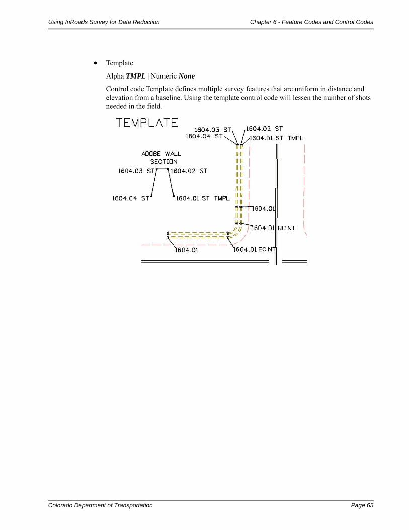
Template
Alpha TMPL | Numeric None
Control code Template defines multiple survey features that are uniform in distance and elevation from a baseline. Using the template control code will lessen the number of shots needed in the field.

Page 66 Colorado Department of Transportation
Chapter 6 - Feature Codes and Control Codes Using InRoads Survey for Data Reduction
Cross Section
Alpha XS | Numeric None
Control code Cross Section allows any uniform set of corridor shots to be collected efficiently. Start by collecting the start of each new feature, and then continue to collect the shots in a crossing pattern.
Note: When the raw data is imported into the field book it will convert the code XS to the correct feature code.
Colorado Department of Transportation Page 67
Using InRoads Survey for Data Reduction Chapter 6 - Feature Codes and Control Codes
Add to Adjustment Set
Alpha ADJ | Numeric None
Control code Add to Adjustment Set defines a sideshot of an unknown point to be included to the adjustment set data.
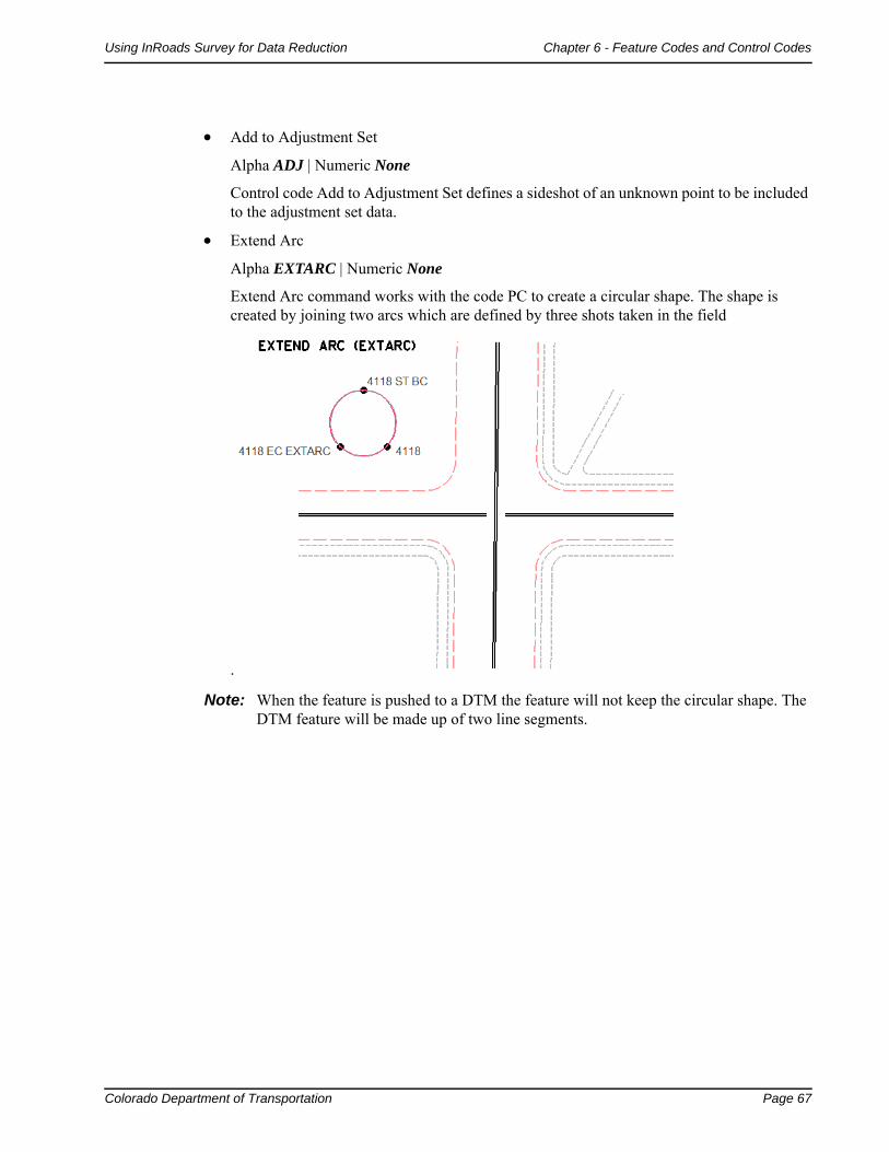
Extend Arc
Alpha EXTARC | Numeric None
Extend Arc command works with the code PC to create a circular shape. The shape is created by joining two arcs which are defined by three shots taken in the field
.
Note: When the feature is pushed to a DTM the feature will not keep the circular shape. The DTM feature will be made up of two line segments.

Page 68 Colorado Department of Transportation
Chapter 6 - Feature Codes and Control Codes Using InRoads Survey for Data Reduction
Colorado Department of Transportation Page 71
Chapter 7 - Fieldbook Edits
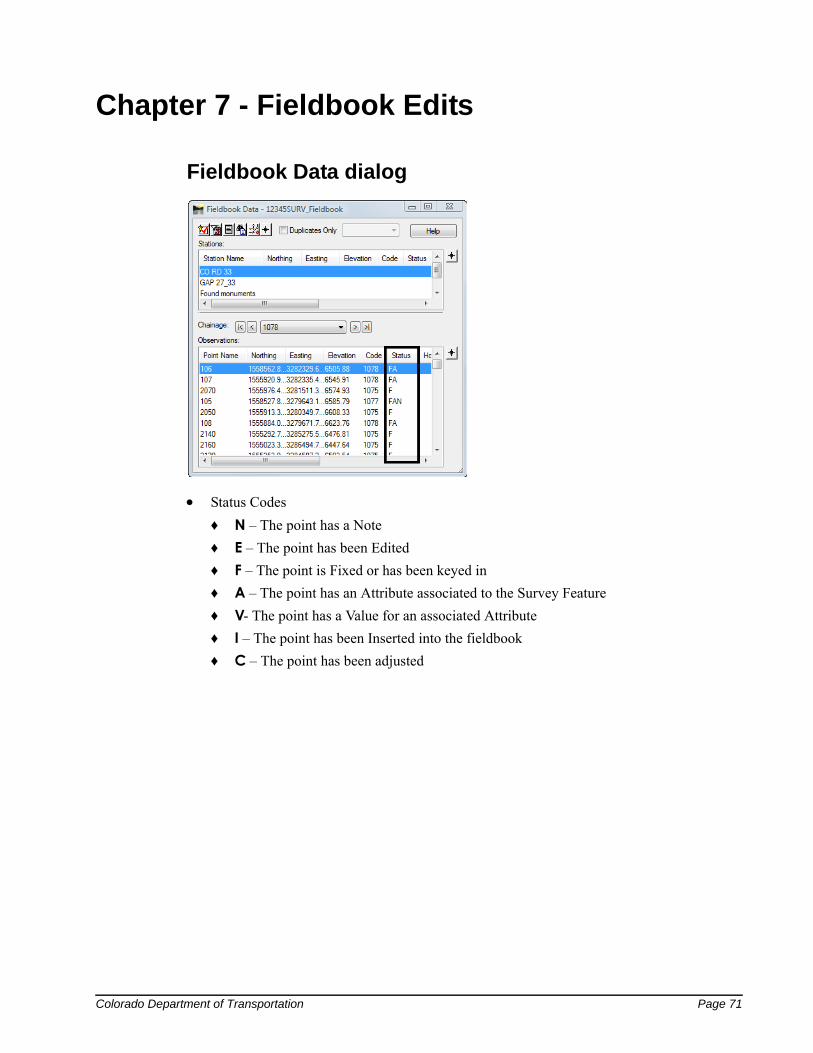
Fieldbook Data dialog
Status Codes
♦ N – The point has a Note
♦ E – The point has been Edited
♦ F – The point is Fixed or has been keyed in
♦ A – The point has an Attribute associated to the Survey Feature
♦ V- The point has a Value for an associated Attribute
♦ I – The point has been Inserted into the fieldbook
♦ C – The point has been adjusted

Page 72 Colorado Department of Transportation
Chapter 7 - Fieldbook Edits Using InRoads Survey for Data Reduction
Find Observation dialog
Dialog items:
Station – key-in field used to locate Station point numbers in the active fieldbook.
Point Name - key-in field used to locate Observation point numbers in the active fieldbook.
Code - key-in field used to locate Alpha or Numeric codes in the active fieldbook.
Fence Mode – used to constrain a lookup area. If a fence is placed in the design file then the item will be activated so fence mode is selectable.
Target Height – locates survey shots based on a target height range
♦ Minimum
♦ Maximum
List – points found based on the selection criteria.
♦ Use the Shift and Ctrl keys to select multiple points in the list.
Apply – locates the points in the active fieldbook and places them in the list section.
Edit – opens the Edit Observation dialog for the selected point numbers.

Colorado Department of Transportation Page 73
Using InRoads Survey for Data Reduction Chapter 7 - Fieldbook Edits
Edit Observation dialog
When editing points in the electronic fieldbook the original raw imported data is not edited. The Edit Observation dialog allows the fields that are not grayed out to be edited. After the point has been edited the point will show an “E” in the Status column of the fieldbook. Edits will also be tracked in the Audit Trail file.
Dialog items:
Point Name – assigned point value in the fieldbook.
♦ Use the arrows to easily cycle through the points.
Type – definition of the point in the fieldbook
♦ Computed – point is defined from measured distances and angles.
♦ Fixed – point is based on a set of coordinates fixed by key-in or by an absolute observation (GPS).
♦ Geometry – point is defined in the Cogo buffer.
Horizontal Observation – measured value
Vertical Observation – measured value
Slope Distance - measured value
Code – feature and control codes
Target Height - prism height above measured point
Notes – any notes added to the shots in the field
Northing, Easting, Elevation - point values for point
Attributes – any additional information collected for the point

Page 74 Colorado Department of Transportation
Chapter 7 - Fieldbook Edits Using InRoads Survey for Data Reduction

Colorado Department of Transportation Page 75
Chapter 8 - Exporting the Fieldbook
Final Export and save
The fieldbook has been corrected until there are no more visible errors. Now the fieldbook will be exported to a DGN, DTM, and ALG files.

Page 76 Colorado Department of Transportation
Chapter 8 - Exporting the Fieldbook Using InRoads Survey for Data Reduction
Colorado Department of Transportation Page 77
Chapter 9 - DTM Evaluation
As part of the deliverables the survey department will provide to the designers is the Surface DTM file. The DTM file is to be an exact copy of what exists in the fieldbook. Meaning that any edits required to the DTM for correction of crossing breaklines or busted elevations is fixed first in the Survey fieldbook and the DTM is then reexported from the fieldbook.
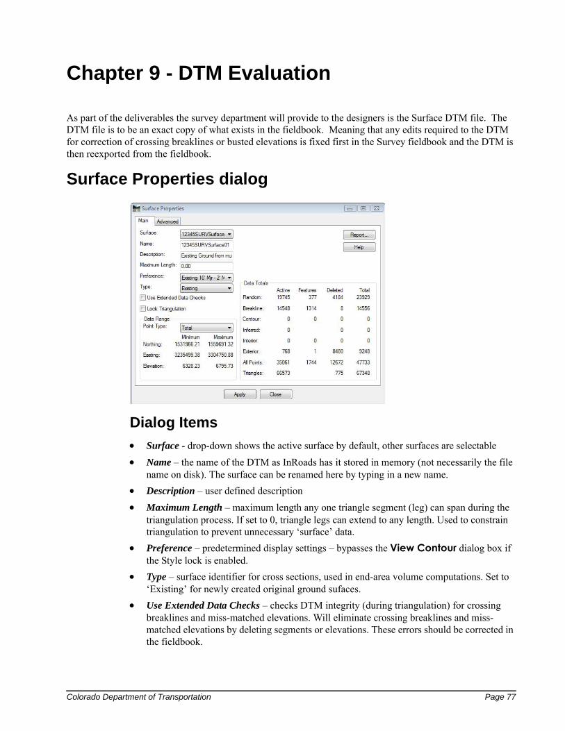
Surface Properties dialog
Dialog Items
Surface - drop-down shows the active surface by default, other surfaces are selectable
Name – the name of the DTM as InRoads has it stored in memory (not necessarily the file name on disk). The surface can be renamed here by typing in a new name.
Description – user defined description
Maximum Length – maximum length any one triangle segment (leg) can span during the triangulation process. If set to 0, triangle legs can extend to any length. Used to constrain triangulation to prevent unnecessary ‘surface’ data.
Preference – predetermined display settings – bypasses the View Contour dialog box if the Style lock is enabled.
Type – surface identifier for cross sections, used in end-area volume computations. Set to ‘Existing’ for newly created original ground sufaces.
Use Extended Data Checks – checks DTM integrity (during triangulation) for crossing breaklines and miss-matched elevations. Will eliminate crossing breaklines and miss-matched elevations by deleting segments or elevations. These errors should be corrected in the fieldbook.
Page 78 Colorado Department of Transportation
Chapter 9 - DTM Evaluation Using InRoads Survey for Data Reduction
Report – generates a separate window summarizing surface properties. The generated report can be printed, written to the CAD file, or stored as an ASCII file
Lock Triangulation – user will not be prompted to retriangulate when surface data is out of date. Not recomended for use.
Data Range – selectable field to show minimum and maximum Northing, Easting, and Elevation of surface featrues.
Data Totals – displays as summary of the suface composition.
Advanced tab – graphic display attribute settings (named symbologies) related to profiles & cross section display of the surface. Also input fields for defining multiple-line parallel offsets for use in profile display. The ‘Use Features Only’ check box instructs InRoads to interpolate cross-section elevations from crossing features vs. from triangle legs.
Data File Naming & Saving
As noted above, a user can rename a surface in the Surface Properties dialog. A critical point to remember is that InRoads is a memory based program. The name given the file on disk can differ from the name used in memory. While they do not have to be the same, it is highly recommended that they share a common name.
Assigning a different name to a surface in the Surface Properties dialog box or by using Surface > Rename Surface simply redefines the surface name as it resides in memory, not on disk.
Renaming a surface in both memory and on disk is a two step process. Use one of the methods described in the preceding paragraph to rename the surface in memory and then use the File > Save As command, using the new name, to save it to disk.

Using InRoads Survey for Data Reduction Page 79
Index

Page 80 Colorado Department of Transportation
Using InRoads Survey for Data Reduction
Related Documents