Using GB-SAR technique to monitor slow moving landslide Linhsia Noferini a , Massimiliano Pieraccini a, ⁎ , Daniele Mecatti a , Giovanni Macaluso a , Carlo Atzeni a , Matteo Mantovani b , Gianluca Marcato b , Alessandro Pasuto b , Sandro Silvano b , Fabrizio Tagliavini b a Department of Electronics and Telecommunications, University of Florence, Italy b National Research Council, Institute for Hydro-geological Protection, Padua, Italy Received 27 October 2006; received in revised form 30 July 2007; accepted 20 September 2007 Available online 29 September 2007 Abstract A Ground-Based SAR (GB-SAR) interferometer was employed to measure the surface displacements of a landslide occurring in the Carnian Alps, north-eastern Italy, which has affected a national road and seriously damaged a road tunnel still under construction. Moreover, since the landslide is located on the left bank of the Tagliamento River Valley, it is feared that this mass movement might dam the river, creating a basin that would increase natural hazard for the valley inhabitants. The data collected from December 2002 to July 2005 by a conventional monitoring system, consisting of a GPS network and boreholes equipped with inclinometric tubes, showed that the landslide was moving at a quasi-constant rate of about 3 cm per year. Due to the slow deformation rate of the landslide, a recently developed GB-SAR technique based on the analysis of a restricted ensemble of coherent points was used. Two surveys, each lasting two days, were planned in December 2004 and July 2005, in order to map and measure the surface displacements that occurred over time. The results from the radar were compared with the ones derived from the GPS monitoring network. An agreement was achieved among the data collected, showing the capability of the GB-SAR technique to measure displacements even within a time span of several months between the surveys. © 2007 Elsevier B.V. All rights reserved. Keywords: Landslide; Remote sensing; Monitoring; Radar 1. Introduction Landslides are a major geological hazard since they are widespread dynamic processes that cause damage, and even loss of life, every year. Development of urban areas and expanded land use in mountain regions has increased the incidence of landslide disasters. The enormous damage caused by landslides can be reduced by means of monitoring systems used for mitigation strategies. Monitoring systems help to forecast the evolution of an area, analyse the kinematics and geometry of failures, and define the history of a failed slope. Conventional monitoring techniques, such as inclinometers, extensometers or GPS networks (Keaton and Degraff, 1996; Mikkelsen, 1996; Angeli et al., 2000; Gili et al., 2000) provide information on accessible points throughout landslide areas. Space- borne or ground-based synthetic aperture radar (SAR) interferometry has been shown to be an effective complementary tool for landslide monitoring (Rott et al., 1999; Pieraccini et al., 2002; Tarchi et al., 2003; Available online at www.sciencedirect.com Engineering Geology 95 (2007) 88 – 98 www.elsevier.com/locate/enggeo ⁎ Corresponding author. E-mail address: [email protected] (M. Pieraccini). 0013-7952/$ - see front matter © 2007 Elsevier B.V. All rights reserved. doi:10.1016/j.enggeo.2007.09.002

Welcome message from author
This document is posted to help you gain knowledge. Please leave a comment to let me know what you think about it! Share it to your friends and learn new things together.
Transcript
Available online at www.sciencedirect.com
5 (2007) 88–98www.elsevier.com/locate/enggeo
Engineering Geology 9
Using GB-SAR technique to monitor slow moving landslide
Linhsia Noferinia, Massimiliano Pieraccinia,⁎, Daniele Mecattia, Giovanni Macalusoa,Carlo Atzenia, Matteo Mantovanib, Gianluca Marcatob, Alessandro Pasutob,
Sandro Silvanob, Fabrizio Tagliavinib
a Department of Electronics and Telecommunications, University of Florence, Italyb National Research Council, Institute for Hydro-geological Protection, Padua, Italy
Received 27 October 2006; received in revised form 30 July 2007; accepted 20 September 2007Available online 29 September 2007
Abstract
A Ground-Based SAR (GB-SAR) interferometer was employed to measure the surface displacements of a landslide occurring inthe Carnian Alps, north-eastern Italy, which has affected a national road and seriously damaged a road tunnel still underconstruction. Moreover, since the landslide is located on the left bank of the Tagliamento River Valley, it is feared that this massmovement might dam the river, creating a basin that would increase natural hazard for the valley inhabitants. The data collectedfrom December 2002 to July 2005 by a conventional monitoring system, consisting of a GPS network and boreholes equipped withinclinometric tubes, showed that the landslide was moving at a quasi-constant rate of about 3 cm per year. Due to the slowdeformation rate of the landslide, a recently developed GB-SAR technique based on the analysis of a restricted ensemble ofcoherent points was used. Two surveys, each lasting two days, were planned in December 2004 and July 2005, in order to map andmeasure the surface displacements that occurred over time. The results from the radar were compared with the ones derived fromthe GPS monitoring network. An agreement was achieved among the data collected, showing the capability of the GB-SARtechnique to measure displacements even within a time span of several months between the surveys.© 2007 Elsevier B.V. All rights reserved.
Keywords: Landslide; Remote sensing; Monitoring; Radar
1. Introduction
Landslides are a major geological hazard since theyare widespread dynamic processes that cause damage,and even loss of life, every year. Development of urbanareas and expanded land use in mountain regions hasincreased the incidence of landslide disasters. Theenormous damage caused by landslides can be reducedby means of monitoring systems used for mitigation
⁎ Corresponding author.E-mail address: [email protected] (M. Pieraccini).
0013-7952/$ - see front matter © 2007 Elsevier B.V. All rights reserved.doi:10.1016/j.enggeo.2007.09.002
strategies. Monitoring systems help to forecast theevolution of an area, analyse the kinematics andgeometry of failures, and define the history of a failedslope. Conventional monitoring techniques, such asinclinometers, extensometers or GPS networks (Keatonand Degraff, 1996; Mikkelsen, 1996; Angeli et al.,2000; Gili et al., 2000) provide information onaccessible points throughout landslide areas. Space-borne or ground-based synthetic aperture radar (SAR)interferometry has been shown to be an effectivecomplementary tool for landslide monitoring (Rottet al., 1999; Pieraccini et al., 2002; Tarchi et al., 2003;
89L. Noferini et al. / Engineering Geology 95 (2007) 88–98
Strozzi et al., 2005; Colesanti and Wasowski, 2006) as itproduces displacement maps even over large andinaccessible areas. In particular, it allows displacementcomponents along the sensor-target line of sight (LOS)to be detected with millimetric precision and all over theilluminated area.
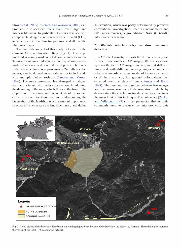
The landslide subject of this study is located in theCarnian Alps, north-eastern Italy (Fig. 1). The slopeinvolved is mainly made up of dolomite and calcareousTriassic formations underlying a thick quaternary covermade of moraine and scree slope deposits. The land-slide, whose volume is approximately 24 million cubicmetres, can be defined as a rotational rock-block slidewith multiple failure surfaces (Cruden and Varnes,1996). The mass movement has damaged a nationalroad and a tunnel still under construction. In addition,the damming of the river, which flows at the base of theslope, has to be taken into account should a suddencollapse occur. For these reasons, understanding thekinematics of the landslide is of paramount importance.In order to better assess the landslide hazard and define
Fig. 1. Aerial picture of the landslide. The darker contour highlights the activethe vertex of the local GPS monitoring network.
its evolution, which was partly determined by previousconventional investigations such as inclinometer andGPS measurements, a ground-based SAR (GB-SAR)interferometer was used.
2. GB-SAR interferometry for slow movementdetection
SAR interferometry exploits the differences in phasebetween two complex SAR images. With space-bornesystems the two SAR images are acquired at differenttimes and with different viewing angles in order toretrieve a three-dimensional model of the scene imaged,or if there are any, the ground deformations thatoccurred over the elapsed time (Bamler and Hartl,1998). The time and the baseline between two imagesare the main sources of decorrelation, which bydeteriorating the interferometric data quality, constitutesthe main limit of this technique. The coherence (Zebkerand Villasenor, 1992) is the parameter that is quitecommonly used to evaluate the interferometric data
part of the landslide, the lighter the dormant. The red triangles represent
90 L. Noferini et al. / Engineering Geology 95 (2007) 88–98
quality. The higher the coherence of a given pixel, thehigher quality of its phase will be. Changes in time ofthe relative positions and of the dielectric properties of thescatterers within the resolution cell strongly decrease thecoherence (temporal decorrelation), making interferometryunfeasible after a certain lapse of time. On the other hand,imaging from different acquisition geometry depends onslightly different projections along the LOSof the scattererswithin the cell and suffers from volume decorrelation.
Moreover, signal propagation through different atmo-spheric conditions causes decorrelation.Many procedureshave been developed over recent years in order tocompensate for the loss of coherence and increase in thenumber of images available for interferometric analysis(Ferretti et al., 2001; Berardino et al., 2002). Ferretti et al.,2001, showed that the set of available images could beincreased at the cost of providing information on a limitednumber of pixels, whose phase could still be interfero-metrically processed. These pixels, called permanentscatterers, are selected according to the amplitudedispersion index, being only slightly influenced by thestandard decorrelation sources.
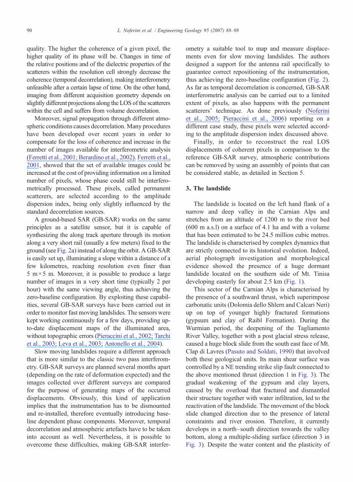
A ground-based SAR (GB-SAR) works on the sameprinciples as a satellite sensor, but it is capable ofsynthesizing the along track aperture through its motionalong a very short rail (usually a few meters) fixed to theground (see Fig. 2a) instead of along the orbit. AGB-SARis easily set up, illuminating a slope within a distance of afew kilometres, reaching resolution even finer than5 m×5 m. Moreover, it is possible to produce a largenumber of images in a very short time (typically 2 perhour) with the same viewing angle, thus achieving thezero-baseline configuration. By exploiting these capabil-ities, several GB-SAR surveys have been carried out inorder to monitor fast moving landslides. The sensors werekept working continuously for a few days, providing up-to-date displacement maps of the illuminated area,without topographic errors (Pieraccini et al., 2002; Tarchiet al., 2003; Leva et al., 2003; Antonello et al., 2004).
Slow moving landslides require a different approachthat is more similar to the classic two pass interferom-etry. GB-SAR surveys are planned several months apart(depending on the rate of deformation expected) and theimages collected over different surveys are comparedfor the purpose of generating maps of the occurreddisplacements. Obviously, this kind of applicationimplies that the instrumentation has to be dismountedand re-installed, therefore eventually introducing base-line dependent phase components. Moreover, temporaldecorrelation and atmospheric artefacts have to be takeninto account as well. Nevertheless, it is possible toovercome these difficulties, making GB-SAR interfer-
ometry a suitable tool to map and measure displace-ments even for slow moving landslides. The authorsdesigned a support for the antenna rail specifically toguarantee correct repositioning of the instrumentation,thus achieving the zero-baseline configuration (Fig. 2).As far as temporal decorrelation is concerned, GB-SARinterferometric analysis can be carried out to a limitedextent of pixels, as also happens with the permanentscatterers' technique. As done previously (Noferiniet al., 2005; Pieraccini et al., 2006) reporting on adifferent case study, these pixels were selected accord-ing to the amplitude dispersion index discussed above.
Finally, in order to reconstruct the real LOSdisplacements of coherent pixels in comparison to thereference GB-SAR survey, atmospheric contributionscan be removed by using an assembly of points that canbe considered stable, as detailed in Section 5.
3. The landslide
The landslide is located on the left hand flank of anarrow and deep valley in the Carnian Alps andstretches from an altitude of 1200 m to the river bed(600 m a.s.l) on a surface of 4.1 ha and with a volumethat has been estimated to be 24.5 million cubic metres.The landslide is characterised by complex dynamics thatare strictly connected to its historical evolution. Indeed,aerial photograph investigation and morphologicalevidence showed the presence of a huge dormantlandslide located on the southern side of Mt. Tinisadeveloping easterly for about 2.5 km (Fig. 1).
This sector of the Carnian Alps is characterised bythe presence of a southward thrust, which superimposecarbonatic units (Dolomia dello Shlern and Calcari Neri)up on top of younger highly fractured formations(gypsum and clay of Raibl Formation). During theWurmian period, the deepening of the TagliamentoRiver Valley, together with a post glacial stress release,caused a huge block slide from the south east face of Mt.Clap di Lavres (Pasuto and Soldati, 1990) that involvedboth these geological units. Its main shear surface wascontrolled by a NE trending strike slip fault connected tothe above mentioned thrust (direction 1 in Fig. 3). Thegradual weakening of the gypsum and clay layers,caused by the overload that fractured and dismantledtheir structure together with water infiltration, led to thereactivation of the landslide. The movement of the blockslide changed direction due to the presence of lateralconstraints and river erosion. Therefore, it currentlydevelops in a north–south direction towards the valleybottom, along a multiple-sliding surface (direction 3 inFig. 3). Despite the water content and the plasticity of
Fig. 2. The used GB-SAR instrumentation: the upper picture is taken from behind the radar and the illuminated scene is well visible in the distance;the lower one is a close-up of the radar instrumentation.
91L. Noferini et al. / Engineering Geology 95 (2007) 88–98
the material involved that increase the instability of theslope (Morgenstern, 1992), the main factor that causesthe deformation is a loading phenomena caused by thepresence of dolomite and limestone over the gypsumand the clay that have been completely remoulded andplasticized (Genovois and Tecca, 1984).
In the early 1990s, construction of a 2 km long roadtunnel was started in this stretch to bypass a rock fallhazard area. During the construction of the tunnel, thestate of activity of the landslide became evident. Thetunnel started to show increasingly serious damage along
the initial 300m from the east entrance and because of thisit has not yet been possible to open the tunnel to traffic.
4. Conventional monitoring system
The stability problems led the authorities to plan aseries of investigations in order to assess the magnitude ofthe deformations, understand the geometry of thelandslide, forecast future scenarios and consider possiblecountermeasures to stabilize the slope. Seven topographicsurveys and levelling investigations were carried out and
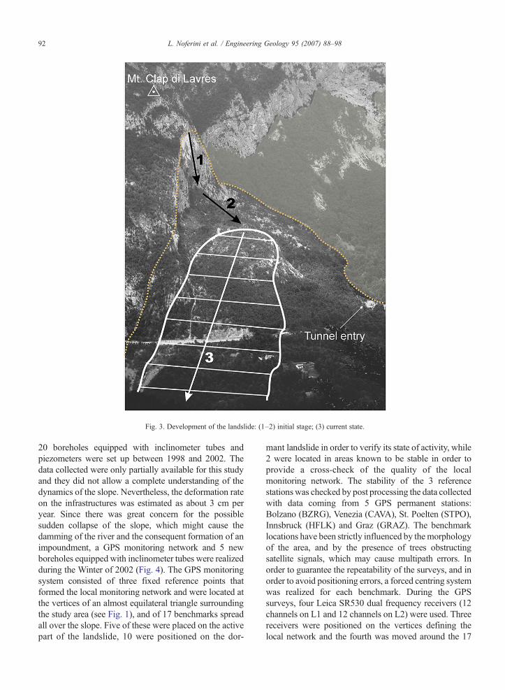
Fig. 3. Development of the landslide: (1–2) initial stage; (3) current state.
92 L. Noferini et al. / Engineering Geology 95 (2007) 88–98
20 boreholes equipped with inclinometer tubes andpiezometers were set up between 1998 and 2002. Thedata collected were only partially available for this studyand they did not allow a complete understanding of thedynamics of the slope. Nevertheless, the deformation rateon the infrastructures was estimated as about 3 cm peryear. Since there was great concern for the possiblesudden collapse of the slope, which might cause thedamming of the river and the consequent formation of animpoundment, a GPS monitoring network and 5 newboreholes equipped with inclinometer tubes were realizedduring the Winter of 2002 (Fig. 4). The GPS monitoringsystem consisted of three fixed reference points thatformed the local monitoring network and were located atthe vertices of an almost equilateral triangle surroundingthe study area (see Fig. 1), and of 17 benchmarks spreadall over the slope. Five of these were placed on the activepart of the landslide, 10 were positioned on the dor-
mant landslide in order to verify its state of activity, while2 were located in areas known to be stable in order toprovide a cross-check of the quality of the localmonitoring network. The stability of the 3 referencestationswas checked by post processing the data collectedwith data coming from 5 GPS permanent stations:Bolzano (BZRG), Venezia (CAVA), St. Poelten (STPO),Innsbruck (HFLK) and Graz (GRAZ). The benchmarklocations have been strictly influenced by themorphologyof the area, and by the presence of trees obstructingsatellite signals, which may cause multipath errors. Inorder to guarantee the repeatability of the surveys, and inorder to avoid positioning errors, a forced centring systemwas realized for each benchmark. During the GPSsurveys, four Leica SR530 dual frequency receivers (12channels on L1 and 12 channels on L2) were used. Threereceivers were positioned on the vertices defining thelocal network and the fourth was moved around the 17
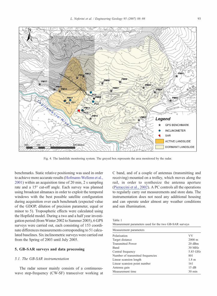
Fig. 4. The landslide monitoring system. The greyed box represents the area monitored by the radar.
Table 1Measurement parameters used for the two GB-SAR surveys
Measurement parameters
Polarisation VVTarget distance 2000 mTransmitted Power 20 dBmBand 30 MHzCentral frequency 5.85 GHzNumber of transmitted frequencies 801Linear scansion length 1.8 mLinear scansion point number 161Antenna gain 15 dBMeasurement time 30 min
93L. Noferini et al. / Engineering Geology 95 (2007) 88–98
benchmarks. Static relative positioning was used in orderto achieve more accurate results (Hofmann-Wellenn et al.,2001) within an acquisition time of 20 min, 2 s samplingrate and a 15° cut-off angle. Each survey was plannedusing broadcast almanacs in order to exploit the temporalwindows with the best possible satellite configurationduring acquisition over each benchmark (expected valueof the GDOP, dilution of precision parameter, equal orminor to 5). Tropospheric effects were calculated usingthe Hopfield model. During a two and a half year investi-gation period (fromWinter 2002 to Summer 2005), 6GPSsurveys were carried out, each consisting of 153 coordi-nate differencesmeasurements corresponding to 51 calcu-lated baselines. Six inclinometric surveys were carried outfrom the Spring of 2003 until July 2005.
5. GB-SAR surveys and data processing
5.1. The GB-SAR instrumentation
The radar sensor mainly consists of a continuous-wave step-frequency (CW-SF) transceiver working at
C band, and of a couple of antennas (transmitting andreceiving) mounted on a trolley, which moves along therail, in order to synthesize the antenna aperture(Pieraccini et al., 2002). A PC controls all the operationsto regularly carry out measurements and store data. Theinstrumentation does not need any additional housingand can operate under almost any weather conditionsand sun illumination.
94 L. Noferini et al. / Engineering Geology 95 (2007) 88–98
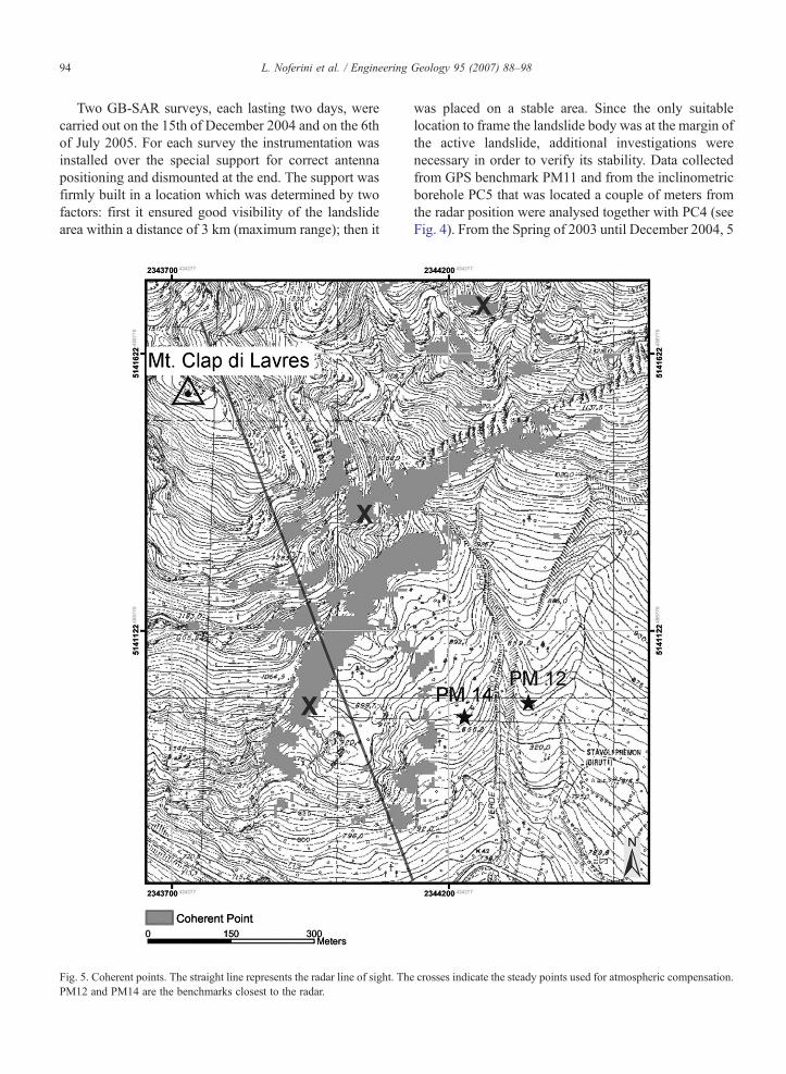
Two GB-SAR surveys, each lasting two days, werecarried out on the 15th of December 2004 and on the 6thof July 2005. For each survey the instrumentation wasinstalled over the special support for correct antennapositioning and dismounted at the end. The support wasfirmly built in a location which was determined by twofactors: first it ensured good visibility of the landslidearea within a distance of 3 km (maximum range); then it
Fig. 5. Coherent points. The straight line represents the radar line of sight. ThPM12 and PM14 are the benchmarks closest to the radar.
was placed on a stable area. Since the only suitablelocation to frame the landslide body was at the margin ofthe active landslide, additional investigations werenecessary in order to verify its stability. Data collectedfrom GPS benchmark PM11 and from the inclinometricborehole PC5 that was located a couple of meters fromthe radar position were analysed together with PC4 (seeFig. 4). From the Spring of 2003 until December 2004, 5
e crosses indicate the steady points used for atmospheric compensation.
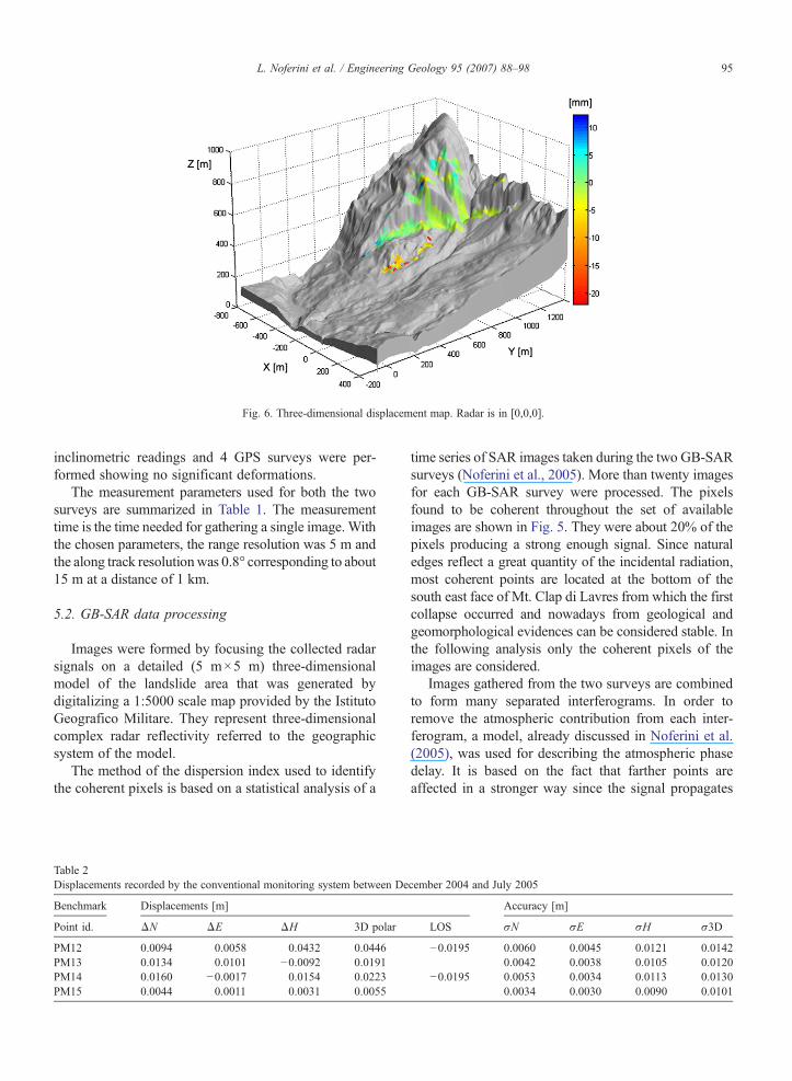
Fig. 6. Three-dimensional displacement map. Radar is in [0,0,0].
95L. Noferini et al. / Engineering Geology 95 (2007) 88–98
inclinometric readings and 4 GPS surveys were per-formed showing no significant deformations.
The measurement parameters used for both the twosurveys are summarized in Table 1. The measurementtime is the time needed for gathering a single image. Withthe chosen parameters, the range resolution was 5 m andthe along track resolutionwas 0.8° corresponding to about15 m at a distance of 1 km.
5.2. GB-SAR data processing
Images were formed by focusing the collected radarsignals on a detailed (5 m×5 m) three-dimensionalmodel of the landslide area that was generated bydigitalizing a 1:5000 scale map provided by the IstitutoGeografico Militare. They represent three-dimensionalcomplex radar reflectivity referred to the geographicsystem of the model.
The method of the dispersion index used to identifythe coherent pixels is based on a statistical analysis of a
Table 2Displacements recorded by the conventional monitoring system between De
Benchmark Displacements [m]
Point id. ΔN ΔE ΔH 3D polar
PM12 0.0094 0.0058 0.0432 0.0446PM13 0.0134 0.0101 −0.0092 0.0191PM14 0.0160 −0.0017 0.0154 0.0223PM15 0.0044 0.0011 0.0031 0.0055
time series of SAR images taken during the two GB-SARsurveys (Noferini et al., 2005). More than twenty imagesfor each GB-SAR survey were processed. The pixelsfound to be coherent throughout the set of availableimages are shown in Fig. 5. They were about 20% of thepixels producing a strong enough signal. Since naturaledges reflect a great quantity of the incidental radiation,most coherent points are located at the bottom of thesouth east face of Mt. Clap di Lavres from which the firstcollapse occurred and nowadays from geological andgeomorphological evidences can be considered stable. Inthe following analysis only the coherent pixels of theimages are considered.
Images gathered from the two surveys are combinedto form many separated interferograms. In order toremove the atmospheric contribution from each inter-ferogram, a model, already discussed in Noferini et al.(2005), was used for describing the atmospheric phasedelay. It is based on the fact that farther points areaffected in a stronger way since the signal propagates
cember 2004 and July 2005
Accuracy [m]
LOS σN σE σH σ3D
−0.0195 0.0060 0.0045 0.0121 0.01420.0042 0.0038 0.0105 0.0120
−0.0195 0.0053 0.0034 0.0113 0.01300.0034 0.0030 0.0090 0.0101
96 L. Noferini et al. / Engineering Geology 95 (2007) 88–98
along a longer path through the atmosphere. Theatmospheric phase is written as a polynomial of therange r:
uatm ¼ c0 þ c1 � r þ c2 � r2 ð1Þwhere the coefficients ci are to be estimated according tothe phases observed on a particular ensemble of pixelschosen as they are stable. In the present case, the chosenpixels are the black crosses highlighted on Fig. 5.
The final LOS displacement map was obtained byaveraging all the interferograms, and it suffers from phaseambiguity (Goldstein et al., 1988) which means thatdisplacements exceeding λ /4, λ, is the transmitted centralwavelength, are mapped within the interval (−λ /4,λ /4]by adding + or −λ /2. In the actual viewing geometry,positive signs represent motion departing from the radartowards the upper part of the mountain that is quiteunrealistic. This is due to phase ambiguity that is solved inthe next paragraph when the final terrain movement radarmap is presented.
The standard deviation across the set of all theinterferograms was used as uncertainty on each coherentpixel. Globally, measurement uncertaintywas calculated asthemean of the standard deviation over the coherent pixels.
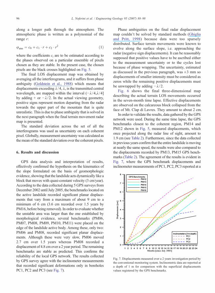
Fig. 7. Displacements measured over a 2 years investigation period bythe conventional monitoring system. Inclinometric data are reported ata depth of 1 m for comparison with the superficial displacementsvalues registered by the GPS benchmarks.
6. Results and discussion
GPS data analysis and interpretation of results,effectively confirmed the hypothesis on the kinematics ofthe slope formulated on the basis of geomorphologicevidence, showing that the landslide acts dynamically like ablock that moves with quasi-constant velocity (3 cm/year).According to the data collected during 5 GPS surveys fromDecember 2002 until July 2005, the benchmarks located onthe active landslide recorded significant planar displace-ments that vary from a maximum of about 9 cm to aminimum of 6 cm (3.6 cm recorded over 1.5 years byPM16, before being removed). In order to evaluatewhetherthe unstable area was larger than the one established bymorphological evidence, several benchmarks (PM06,PM07, PM08, PM09, PM10, PM11) were placed on theedge of the landslide active body. Among these, only two:PM06 and PM08, recorded significant planar displace-ments. Although these were very slow, PM06 moved2.7 cm over 1.5 years whereas PM08 recorded adisplacement of 4.8 cmover a 2 year period. The remainingbenchmarks are stable as predicted. This confirms thereliability of the local GPS network. The results collectedby GPS survey agree with the inclinometer measurementsthat recorded significant deformations only in boreholesPC1, PC2 and PC3 (see Fig. 7).
Phase ambiguities on the final radar displacementmap couldn't be solved by standard methods (Ghigliaand Pritt, 1998) because data were too sparselydistributed. Surface terrain movements were known toevolve along the surface slope, i.e. approaching theradar (negative sign displacements). It can be reasonablysupposed that positive values have to be ascribed eitherto the measurement uncertainty or to the cycles lostbecause of phase wrapping. The uncertainty, estimatedas discussed in the previous paragraph, was ±3 mm sodisplacements of smaller intensity must be considered aszeros while the remaining positive displacements mustbe unwrapped by adding −λ / 2.
Fig. 6 shows the final three-dimensional mapdescribing the actual terrain LOS movements occurredin the seven-month time lapse. Effective displacementsare observed on the calcareous block collapsed from theface of Mt. Clap di Lavres. They amount to about 2 cm.
In order to validate the results, data gathered by theGPSnetwork were used. During the same time lapse, the GPSbenchmarks closest to the coherent region, PM14 andPM12 shown in Fig. 5, measured displacements, whichonce projected along the radar line of sight, amount to1.9 cm (see Table 2). Furthermore, since the data collectedin previous years confirm that the entire landslide ismovingat nearly the same speed, the results were also compared tothe displacements recorded by PM13, PM15 GPS bench-marks (Table 2). The agreement of the results is evident inFig. 7, where the GPS benchmark displacements andinclinometer measurements of PC1, PC2, PC3 reported at a
97L. Noferini et al. / Engineering Geology 95 (2007) 88–98
depth of 1 m show a quasi-constant rate of deformationaveraging 1.3 cm in the time span occurred between the twoGB-SAR surveys.
7. Conclusions
Remote sensing techniques have the very appreciableadvantage of providingwidespread informationwithout theneed for a physical survey of unstable slopes. Ground-based radar interferometry has already been recognized asan effective tool for remote monitoring of fast movinglandslides. The sensor can operate over a wide area underany weather conditions, continuously and over a long time,producing deformation maps with millimetric accuracy.
In the present body of work, a ground-based interfer-ometer was employed to measure and map slow dis-placements of a landslide which was monitored byconventional systems over recent years. Two GB-SARsurveys were carried out with a seven months time lapsebetween them. The accuracy of the results and theirreliability has been proven by the agreement with thedata collected from conventional monitoring systems(e.g. GPS, inclinometers, etc.). It is worth noting that thestability of the GB-SAR location was checked byconventional measurements showing a good example ofintegration between different monitoring techniques.
The GB-SAR results have been useful for theinterpretation of landslide kinematics and its long-termevolution. Moreover the data collected may be useful tocalibrate and validate geotechnical models.
Further developments could include the possibleimplementation of a completely automated alarm sys-tem able to verify the deformation field of a landslideand assess hazard in real time.
Acknowledgements
The equipment used in this work was designed andconstructed with the support of IDS-Ingegneria dei SistemiSpA, Pisa (Italy), and it remains the property of thiscompany.
References
Angeli, M.G., Pasuto, A., Silvano, S., 2000. A critical review oflandslidemonitoring experiences. EngineeringGeology 55, 133–147.
Antonello, G., Casagli, N., Farina, P., Leva, D., Nico, G., Sieber, A.J.,Tarchi, D., 2004. Ground-based SAR interferometry for monitor-ing mass movements. Landslides 1, 21–28.
Bamler, R., Hartl, P., 1998. Synthetic aperture radar interferometry.Inverse Problems 14, R1–R154.
Berardino, P., Fornaro, G., Lanari, R., 2002. A new algorithm forsurface deformation monitoring based on small baseline differen-
tial SAR interferograms. Transactions on Geoscience and RemoteSensing 40 (11), 2375–2383.
Colesanti, C., Wasowski, J., 2006. Investigating landslides with space-borne Synthetic Aperture Radar (SAR) interferometry. Engineer-ing Geology 88, 173–199.
Cruden, D.M., Varnes, D.J., 1996. Landslides types and processes. In:Turner, A.K., Schuster, R.L. (Eds.), Landslides: Investigation andMitigation. Transportation Research Board Special Report, vol. 247.National Academy Press, WA, pp. 36–75.
Ferretti, A., Prati, C., Rocca, F., 2001. Permanent scatterers in SARinterferometry. IEEE Transactions on Geoscience and RemoteSensing 39 (1), 8–20.
Genovois, R., Tecca, P.R., 1984. Alcune considerazioni sulledeformazioni gravitative profonde in argille sovraconsolidate.Bolletino della Societa Geologica Italiana 130, 717–729.
Ghiglia, D.C., Pritt, M.D., 1998. Two-dimensional Phase Unwrapping:Theory, Algorithms and Software. JohnWiley&Sons, Inc., NewYork.
Gili, J.A., Corominas, J., Rius, J., 2000. Using global positioningsystem techniques in landslide monitoring. Engineering Geology55, 167–192.
Goldstein, R.M., Zebker, H.A., Werner, C.L., 1988. Satellite radarinterferometry: two-dimensional phase unwrapping. Radio Science23, 713–720.
Hofmann-Wellenn, B., Lichtenegger, H., Collins, J., 2001. GPS Theoryand Practice, 5th revised edit. Springer Verlag, Wien.
Keaton, J.R., Degraff, J.V., 1996. Surface observation and geologicmapping. Landslides. Investigation and Mitigation. U.S. Trans-port. Res. Boards Special Report, vol. 176. National Academy ofSciences, Washington, pp. 178–230.
Leva, D., Nico, G., Tarchi, D., Fortuny, J., Sieber, A.J., 2003.Temporal analysis of a landslide by means of a ground-based SARinterferometer. IEEE Transactions on Geoscience and RemoteSensing 41, 745–752.
Mikkelsen, P.E., 1996. Field instrumentation. Landslides. Investiga-tion and Mitigation. U.S. Transportation Research BoardsSpecial Report, vol. 247. National Academy Press, Washington,DC, pp. 278–315.
Morgenstern, N.R., 1992. The evaluation of slope stability — a25 year perspective. Proc., ASCE Speciality Conference onStability and Performance of Slopes and Embankments II,Berkeley, California. Geotechnical Special Publication, vol. 31.American Society of Civil Engineers, New York, pp. 1–26.
Noferini, L., Pieraccini, M., Mecatti, D., Macaluso, G., Atzeni, C., 2005.Long term landslidemonitoring byGroundBased SAR Interferometer.International Journal of Remote Sensing 27, 1893–1905.
Pasuto, A., Soldati, M., 1990. Rassegna bibliografica sulle deformazionigravitative profonde di versante. Il Quaternario 3 (2), 131–140.
Pieraccini, M., Casagli, N., Luzi, G., Tarchi, D., Mecatti, D., Noferini, L.,Atzeni, C., 2002. Landslide Monitoring by Ground-Based RadarInterferometry: a field test in Valdarno (Italy). International Journal ofRemote Sensing 24, 1385–1391.
Pieraccini, M., Noferini, L., Mecatti, D., Atzeni, C., Teza, G., Galgaro,A., Zaltron, N., 2006. Integration of Radar Interferometry andLaser Scanning for Remote Monitoring of an urban site built on asliding slope. IEEE Transactions on Geoscience and RemoteSensing 44 (9), 2335–2342.
Rott, H., Scheuchl, B., Siegel, A., Grasemann, B., 1999. Monitoringvery slow slope movements by means of SAR interferometry: acase study from a mass waste above a reservoir in the Ötztal Alps,Austria. Geophysical Research Letters 26, 1629–1632.
Strozzi, T., Farina, P., Corsini, A., Ambrosi, C., Thüring, M., Zilger, J.,Wiesmann, A., Wegmüller, U., Werner, C., 2005. Survey and

98 L. Noferini et al. / Engineering Geology 95 (2007) 88–98
monitoring of landslide displacements by means of L-band satelliteSAR interferometry. Landslides 2 (3), 193–201.
Tarchi, D., Casagli, N., Fanti, R., Leva, D., Luzi, G., Pasuto, A.,Pieraccini, M., Silvano, S., 2003. Landslide monitoring by usingground-based SAR interferometry: an example of application
to the Tessina landslide in Italy. Engineering Geology 68 (1–2),15–30.
Zebker, H.A., Villasenor, J., 1992. Decorrelation in InterferometricRadar Echoes. IEEE Transactions on Geoscience and RemoteSensing 30, 950–959.
Related Documents