1 UNIT-I:Network Hardware: LAN – WAN – MAN – Wireless – Home Networks. Network Software: Protocol Hierarchies – Design Issues for the Layers – Connection-oriented and connectionless services – Service Primitives – The Relationship of services to Protocols. Reference Models: OSI Reference Model – TCP/IP reference Model – Comparison of OSI and TCP/IP -Critique of OSI and protocols – Critique of the TCP/IP Reference model. UNIT-I INTRODUCTION A group of two or more computing devices connected via a form of communications technology. For example, a business might use a computer network connected via cables or the Internet in order to gain access to a common server or to share programs, files and other information. Computer Network means an “interconnected collection of autonomous Computers”. Two Computers are said to be interconnected if they can exchange information. The connection usually will be based on a communication medium like copper wire, fiber optics etc., Master/Slave relationship in which one computer forcibly start, stop, or control another computer is not a network, the computers should be autonomous. Difference between a Computer Network and Distributed System. Computer Network Distributed System The Existence of autonomous computers are not transparent (they are visible). The Existence of autonomous computers are transparent (they are not visible). The autonomous computer performs the operation requested by the user. The best processor is selected by the operating system for carrying out the operations requested by the user. The user is aware of his working environment. The user is not aware of his working environment, which is multiple processor in nature but looks like a virtual uniprocessor. All operations (allocation of jobs to processors, files to disks, movement of files) are done explicitly. All operations (allocation of jobs to processors, files to disks, movement of files) are done automatically without the user’s knowledge. Regulation software is enough for computer networks. A software that gives a high degree of cohesiveness and transparency is needed since distributed system is built on top of a network A computer network can be two computers connected: Fig 1.1 Connecting two computer Characteristics of a Computer Network The primary purpose of a computer network is to share resources: You can play a CD music from one computer while sitting on another computer

Welcome message from author
This document is posted to help you gain knowledge. Please leave a comment to let me know what you think about it! Share it to your friends and learn new things together.
Transcript

1
UNIT-I:Network Hardware: LAN – WAN – MAN – Wireless – Home Networks. Network
Software: Protocol Hierarchies – Design Issues for the Layers – Connection-oriented and
connectionless services – Service Primitives – The Relationship of services to Protocols.
Reference Models: OSI Reference Model – TCP/IP reference Model – Comparison of OSI and
TCP/IP -Critique of OSI and protocols – Critique of the TCP/IP Reference model.
UNIT-I
INTRODUCTION
A group of two or more computing devices connected via a form of communications
technology. For example, a business might use a computer network connected via cables or the
Internet in order to gain access to a common server or to share programs, files and other
information.
Computer Network means an “interconnected collection of autonomous
Computers”.
Two Computers are said to be interconnected if they can exchange information.
The connection usually will be based on a communication medium like copper wire,
fiber optics etc.,
Master/Slave relationship in which one computer forcibly start, stop, or control
another computer is not a network, the computers should be autonomous.
Difference between a Computer Network and Distributed System.
Computer Network Distributed System
The Existence of autonomous computers are
not transparent (they are visible).
The Existence of autonomous computers are
transparent (they are not visible).
The autonomous computer performs the
operation requested by the user.
The best processor is selected by the operating
system for carrying out the operations requested
by the user.
The user is aware of his working
environment.
The user is not aware of his working
environment, which is multiple processor in
nature but looks like a virtual uniprocessor.
All operations (allocation of jobs to
processors, files to disks, movement of files)
are done explicitly.
All operations (allocation of jobs to processors,
files to disks, movement of files) are done
automatically without the user’s knowledge.
Regulation software is enough for computer
networks.
A software that gives a high degree of
cohesiveness and transparency is needed since
distributed system is built on top of a network
A computer network can be two computers connected:
Fig 1.1 Connecting two computer
Characteristics of a Computer Network
The primary purpose of a computer network is to share resources:
You can play a CD music from one computer while sitting on another computer

2
You may have a computer that doesn’t have a DVD or BluRay (BD) player. In this case,
you can place a movie disc (DVD or BD) on the computer that has the player, and then
view the movie on a computer that lacks the player
You may have a computer with a CD/DVD/BD writer or a backup system but the other
computer(s) doesn’t (don't) have it. In this case, you can burn discs or make backups on a
computer that has one of these but using data from a computer that doesn’t have a disc
writer or a backup system
You can connect a printer (or a scanner, or a fax machine) to one computer and let other
computers of the network print (or scan, or fax) to that printer (or scanner, or fax
machine)
The computers can be geographically located anywhere
Fig 1.2 Geographically located network
You can place a disc with pictures on one computer and let other computers access those
pictures
You can create files and store them in one computer,then access those files from the other
computer(s) connected to it
Peer-to-Peer network:
Based on their layout (not the physical but the imagined layout, also referred to as
topology), there are various types of networks. A network is referred to as peer-to-peer if
most computers are similar and run workstation operating systems.
In a peer-to-peer network, each computer holds its files and resources. Other computers
can access these resources but a computer that has a particular resource must be turned on
for other computers to access the resource it has. For example, if a printer is connected to
computer A and computer B wants to printer to that printer, computer A must be turned
On.
History Of Computer Network
A computer network, or simply a network, is a collection of computers and other
hardware components interconnected by communication channels that allow sharing of resources
and information. Today, computer networks are the core of modern communication. All modern
aspects of the public switched telephone network (PSTN) are computer-controlled. Telephony
increasingly runs over the Internet Protocol, although not necessarily the public Internet. The
scope of communication has increased significantly in the past decade.
3
This boom in communications would not have been possible without the progressively
advancing computer network. Computer networks, and the technologies that make
communication between networked computers possible, continue to drive computer hardware,
software, and peripherals industries. The expansion of related industries is mirrored by growth in
the numbers and types of people using networks, from the researcher to the home user.
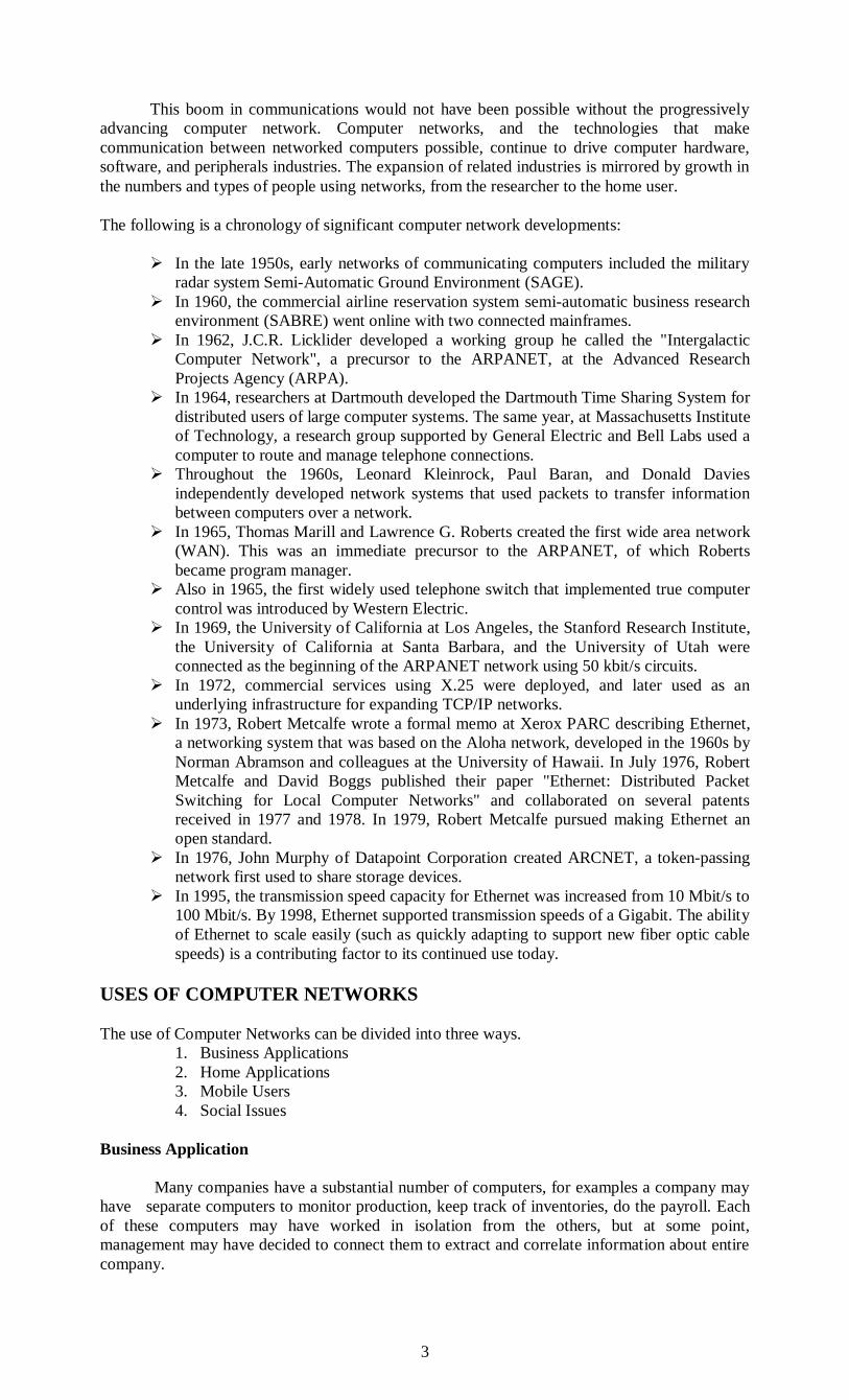
The following is a chronology of significant computer network developments:
In the late 1950s, early networks of communicating computers included the military
radar system Semi-Automatic Ground Environment (SAGE).
In 1960, the commercial airline reservation system semi-automatic business research
environment (SABRE) went online with two connected mainframes.
In 1962, J.C.R. Licklider developed a working group he called the "Intergalactic
Computer Network", a precursor to the ARPANET, at the Advanced Research
Projects Agency (ARPA).
In 1964, researchers at Dartmouth developed the Dartmouth Time Sharing System for
distributed users of large computer systems. The same year, at Massachusetts Institute
of Technology, a research group supported by General Electric and Bell Labs used a
computer to route and manage telephone connections.
Throughout the 1960s, Leonard Kleinrock, Paul Baran, and Donald Davies
independently developed network systems that used packets to transfer information
between computers over a network.
In 1965, Thomas Marill and Lawrence G. Roberts created the first wide area network
(WAN). This was an immediate precursor to the ARPANET, of which Roberts
became program manager.
Also in 1965, the first widely used telephone switch that implemented true computer
control was introduced by Western Electric.
In 1969, the University of California at Los Angeles, the Stanford Research Institute,
the University of California at Santa Barbara, and the University of Utah were
connected as the beginning of the ARPANET network using 50 kbit/s circuits.
In 1972, commercial services using X.25 were deployed, and later used as an
underlying infrastructure for expanding TCP/IP networks.
In 1973, Robert Metcalfe wrote a formal memo at Xerox PARC describing Ethernet,
a networking system that was based on the Aloha network, developed in the 1960s by
Norman Abramson and colleagues at the University of Hawaii. In July 1976, Robert
Metcalfe and David Boggs published their paper "Ethernet: Distributed Packet
Switching for Local Computer Networks" and collaborated on several patents
received in 1977 and 1978. In 1979, Robert Metcalfe pursued making Ethernet an
open standard.
In 1976, John Murphy of Datapoint Corporation created ARCNET, a token-passing
network first used to share storage devices.
In 1995, the transmission speed capacity for Ethernet was increased from 10 Mbit/s to
100 Mbit/s. By 1998, Ethernet supported transmission speeds of a Gigabit. The ability
of Ethernet to scale easily (such as quickly adapting to support new fiber optic cable
speeds) is a contributing factor to its continued use today.
USES OF COMPUTER NETWORKS
The use of Computer Networks can be divided into three ways.
1. Business Applications
2. Home Applications
3. Mobile Users
4. Social Issues
Business Application
Many companies have a substantial number of computers, for examples a company may
have separate computers to monitor production, keep track of inventories, do the payroll. Each
of these computers may have worked in isolation from the others, but at some point,
management may have decided to connect them to extract and correlate information about entire
company.
4
Use of Computer Network for business can be classified as
1. Resource Sharing
2. High Reliability
3. Saving Money
4. Scalability
5. Communication Medium
The goal is resource sharing, to make all programs, equipment, and especially data
available to anyone on the network without regard to the physical location of the resource and
the user.
A second goal is to provide high reliability by having alternative sources of supply. All
files could be replicated on two or three machines, so if one of them is unavailable (due to a
hardware failure), the other copies could be used. In addition, the presence of multiple CPUs
means that if one goes down, the others may be able to take over its work, although at reduced
performance. Military, banking, air traffic control, nuclear reactor safety, and many other
applications, the ability to continue operating in the face of hardware problems is of utmost
importance.
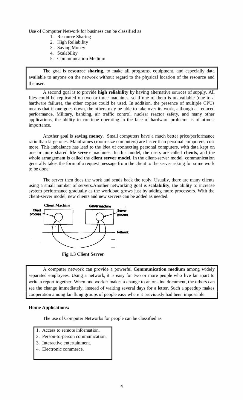
Another goal is saving money. Small computers have a much better price/performance
ratio than large ones. Mainframes (room-size computers) are faster than personal computers, cost
more. This imbalance has lead to the idea of connecting personal computers, with data kept on
one or more shared file server machines. In this model, the users are called clients, and the
whole arrangement is called the client server model. In the client-server model, communication
generally takes the form of a request message from the client to the server asking for some work
to be done.
The server then does the work and sends back the reply. Usually, there are many clients
using a small number of servers.Another networking goal is scalability, the ability to increase
system performance gradually as the workload grows just by adding more processors. With the
client-server model, new clients and new servers can be added as needed.
A computer network can provide a powerful Communication medium among widely
separated employees. Using a network, it is easy for two or more people who live far apart to
write a report together. When one worker makes a change to an on-line document, the others can
see the change immediately, instead of waiting several days for a letter. Such a speedup makes
cooperation among far-flung groups of people easy where it previously had been impossible.
Home Applications:
The use of Computer Networks for people can be classified as
1. Access to remote information.
2. Person-to-person communication.
3. Interactive entertainment.
4. Electronic commerce.
Client Machine
Fig 1.3 Client Server
Model
5
Access to remote information comes in many forms. Information available includes the
Arts, Business, Cooking, Government, Health, History, Hobbies, Recreation, Science, Sports,
Travel and many others. Newspapers will go on-line and be personalized. It will be possible to
download the areas of interest of a person say, politics, big fires, scandals involving celebrities,
and epidemics. The next step beyond newspapers is the on-line digital library. All of the above
applications involve interactions between a person and a remote database.
The second broad category of network use will be person-to-person communication
Electronic mail or email is already widely used by millions of people and will soon contain
audio and video as well as text. Smell in messages will take a bit longer to perfect. Instant
messaging allows two people to type messages at each other in real time. A multiperson version
of this idea is the chat room, in which a group of people can type messages for all to see.
Real-time email will allow remote users to communicate with no delay, possibly seeing
and hearing each other as well. This technology makes it possible to have virtual meetings,
called videoconference, among far-flung people. Virtual meetings could be used for remote
school, getting medical opinions from distant specialists, and numerous other applications.
Worldwide newsgroups, with discussions on every conceivable topic are common among a
select group of people, and this will grow to include the population at large. Here one person
posts a message and all the other subscribers to the newsgroup can read it and can respond with
an answer.
Our third category is entertainment, which is a huge and growing industry. The killer
application here is video on demand. Live television may also become interactive, with the
audience participating in quiz shows, choosing among contestants, and so on. Game playing is
an important application of computer network for people. Multiperson real-time simulation
games, like hide-and-seek in a virtual dungeon, and flight simulators with the players on one
team trying to shoot down the players on the opposing team, 3-dimensional real-time,
photographic-quality moving images, virtual reality games are few to mention.
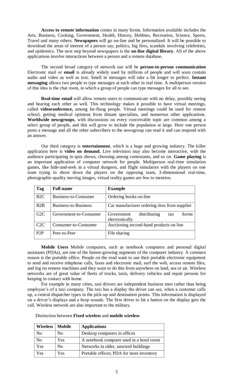
Tag Full name Example
B2C Business-to-Consumer Ordering books on-line
B2B Business-to-Business Car manufacturer ordering tires from supplier
G2C Government-to-Consumer Government distributing tax forms
electronically
C2C Consumer-to-Consumer Auctioning second-hand products on line
P2P Peer-to-Peer File sharing
Mobile Users Mobile computers, such as notebook computers and personal digital
assistants (PDAs), are one of the fastest-growing segments of the computer industry. A common
reason is the portable office. People on the road want to use their portable electronic equipment
to send and receive telephone calls, faxes and electronic mail, surf the web, access remote files,
and log on remote machines and they want to do this from anywhere on land, sea or air. Wireless
networks are of great value of fleets of trucks, taxis, delivery vehicles and repair persons for
keeping in contact with home.
For example in many cities, taxi drivers are independent business men rather than being
employee’s of a taxi company. The taxi has a display the driver can see, when a customer calls
up, a central dispatcher types in the pick-up and destination points. This information is displayed
on a driver’s displays and a beep sounds. The first driver to hit a button on the display gets the
call. Wireless network are also important to the military.
Distinction between Fixed wireless and mobile wireless
Wireless Mobile Applications
No No Desktop computers in offices
No Yes A notebook computer used in a hotel room
Yes No Networks in older, unwired buildings
Yes Yes Portable offices; PDA for store inventory
6
Social issues The widespread introduction of networking has led to
1. Social
2. Ethical and
3. Political problems.
The trouble arises when newsgroups are set up on topics that people contradicting views.
Views posted to such groups may be deeply offensive to some people. Thus the debate rages.
Users rights are violated and freeness of speech is barred. Computer networks offer the potential
for sending anonymous messages, a way to express views without fear of reprisals. This
newfound freedom brings with it many unsolved social, political, and moral issues.
NETWORK HARDWARE There is no generally accepted taxonomy into which all computer networks fit,but two
dimensions Stand out as important.
Transmission Technology
Scale
Transmission Technology: Broadly speaking, there are two types of transmission
technology:
Broadcast networks.
Point-to-point Networks
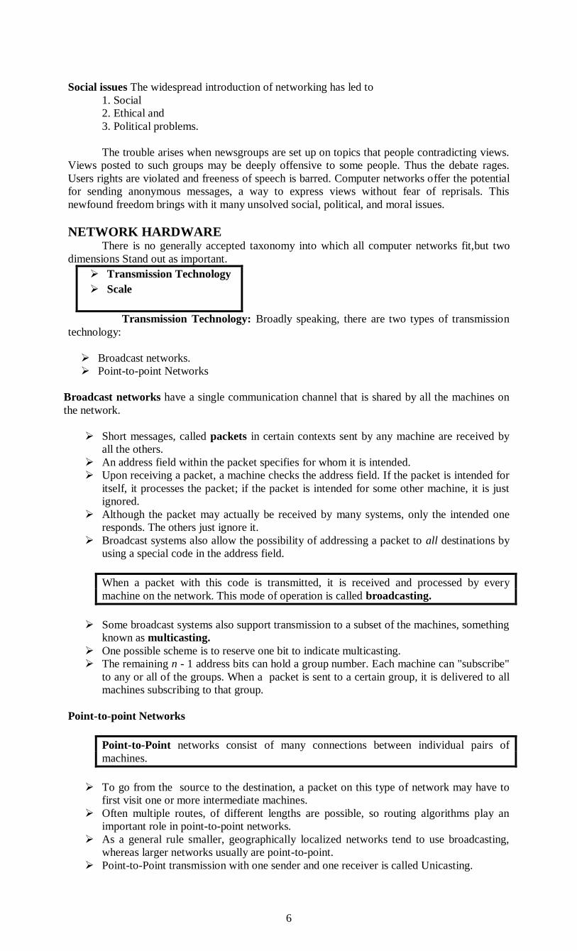
Broadcast networks have a single communication channel that is shared by all the machines on
the network.
Short messages, called packets in certain contexts sent by any machine are received by
all the others.
An address field within the packet specifies for whom it is intended.
Upon receiving a packet, a machine checks the address field. If the packet is intended for
itself, it processes the packet; if the packet is intended for some other machine, it is just
ignored.
Although the packet may actually be received by many systems, only the intended one
responds. The others just ignore it.
Broadcast systems also allow the possibility of addressing a packet to all destinations by
using a special code in the address field.
When a packet with this code is transmitted, it is received and processed by every
machine on the network. This mode of operation is called broadcasting.
Some broadcast systems also support transmission to a subset of the machines, something
known as multicasting.
One possible scheme is to reserve one bit to indicate multicasting.
The remaining n - 1 address bits can hold a group number. Each machine can "subscribe"
to any or all of the groups. When a packet is sent to a certain group, it is delivered to all
machines subscribing to that group.
Point-to-point Networks
Point-to-Point networks consist of many connections between individual pairs of
machines.
To go from the source to the destination, a packet on this type of network may have to
first visit one or more intermediate machines.
Often multiple routes, of different lengths are possible, so routing algorithms play an
important role in point-to-point networks.
As a general rule smaller, geographically localized networks tend to use broadcasting,
whereas larger networks usually are point-to-point.
Point-to-Point transmission with one sender and one receiver is called Unicasting.

7
Computer networks can be classified according to their size:
Personal area network (PAN)
Local area network (LAN)
Metropolitan area network (MAN)
Wide area network (WAN)
Interprocessor Distances Processors located in same Examples
Classification of interconnected processors by scale.
An alternative criterion for classifying networks is their scale. Multiple processor systems
can be arranged by their physical size. At the top are data flow machines, highly parallel
computers with many functional units all working on the same program.
Next come the multicomputers, systems that communicate by sending messages over
very short, very fast buses. Beyond the multicomputers are the true networks, computers that
communicate by exchanging messages over longer cables. These can be divided into local,
metropolitan, and wide area networks, finally, the connection of two or networks are called an
internetwork. The worldwide Internet is a well-known example of an internetwork.
Personal area network
A personal area network (PAN) is a computer network used for data transmission among
devices such as computers, telephones and personal digital assistants.
PANs can be used for communication among the personal devices themselves
(intrapersonal communication), or A PAN is a network that is used for communicating among
computers and computer devices (including telephones) in close proximity of around a few
meters within a room connecting to a higher level network and the Internet (an uplink).
It can be used for communicating between the devices themselves, or for connecting to a
larger network such as the internet PAN’s can be wired or wireless.
PAN’s can be wired with a computer bus such as a universal serial bus: USB (a
serial bus standard for connecting devices to a computer-many devices can be
connected concurrently)
PAN’s can also be wireless through the use of bluetooth (a radio standard
designed for low power consumption for interconnecting computers and devices
such as telephones, printers or keyboards to the computer) or IrDA (infrared data
association) technologies
A wireless personal area network (WPAN) is a PAN carried over wireless network
technologies such as:
INSTEON
IrDA
Wireless USB
Bluetooth
1 m Square meter
10 m Room
100 m Building
1 km Campus
10 km City
100 km Country
1000 km Continent
10000 km Planet
Wide Area Network
Metropolitan Area Network
Personal Area Network
Local area network
The Internet
8
Z-Wave
ZigBee
Body Area Network
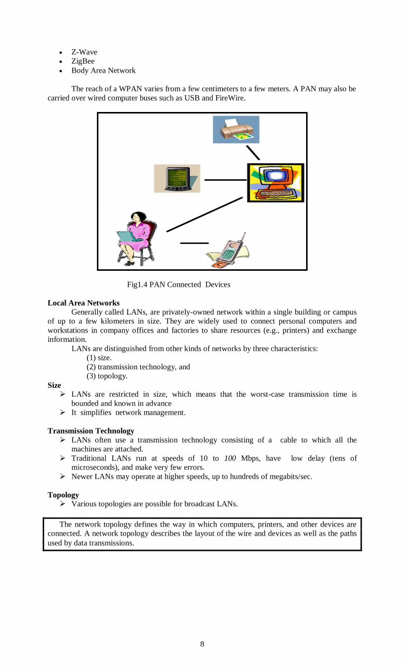
The reach of a WPAN varies from a few centimeters to a few meters. A PAN may also be
carried over wired computer buses such as USB and FireWire.
Fig1.4 PAN Connected Devices
Local Area Networks
Generally called LANs, are privately-owned network within a single building or campus
of up to a few kilometers in size. They are widely used to connect personal computers and
workstations in company offices and factories to share resources (e.g., printers) and exchange
information.
LANs are distinguished from other kinds of networks by three characteristics:
(1) size.
(2) transmission technology, and
(3) topology.
Size
LANs are restricted in size, which means that the worst-case transmission time is
bounded and known in advance
It simplifies network management.
Transmission Technology
LANs often use a transmission technology consisting of a cable to which all the
machines are attached.
Traditional LANs run at speeds of 10 to 100 Mbps, have low delay (tens of
microseconds), and make very few errors.
Newer LANs may operate at higher speeds, up to hundreds of megabits/sec.
Topology
Various topologies are possible for broadcast LANs.
The network topology defines the way in which computers, printers, and other devices are
connected. A network topology describes the layout of the wire and devices as well as the paths
used by data transmissions.

9
Fig 1.5 Toplogies
Bus Topology
Commonly referred to as a linear bus, all the devices on a bus topology are connected by
one single cable.
A linear bus topology consists of a main run of cable with a terminator at each end. All
servers workstations and peripherals are connected to the linear cable
Application of Bus Topology
Transmission Logic
Listen to the bus for traffic
If no traffic is detected, then transmit
Otherwise, if the bus is busy with traffic, wait for a random period of time before
attempting to transmit again
Repeated attempts will be made until the bus is found free
Fig 1.6 Bus Topology used at LAN Network
Collision of Data
Two workstations may find the bus free at the same time
Both would transmit at the same time Collision of data occurs
Both workstations will now wait for a random period of time before attempting to
transmit again
Advantages
Cabling is simple and easy to install in a local setup
Based on well established standards
10
o IEEE 802.3
o Also known as the Ethernet standard
Disadvantages
Sharing of a single data bus
o When the traffic increases the performance deteriorates
Waiting period may reach unacceptable lengths of time under heavy data traffic
Cable fault results in the entire LAN becoming inoperative
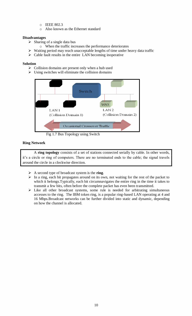
Solution
Collision domains are present only when a hub used
Using switches will eliminate the collision domains
Fig 1.7 Bus Topology using Switch
Ring Network
A ring topology consists of a set of stations connected serially by cable. In other words,
it’s a circle or ring of computers. There are no terminated ends to the cable; the signal travels
around the circle in a clockwise direction.
A second type of broadcast system is the ring.
In a ring, each bit propagates around on its own, not waiting for the rest of the packet to
which it belongs.Typically, each bit circumnavigates the entire ring in the time it takes to
transmit a few bits, often before the complete packet has even been transmitted.
Like all other broadcast systems, some rule is needed for arbitrating simultaneous
accesses to the ring. The IBM token ring, is a popular ring-based LAN operating at 4 and
16 Mbps.Broadcast networks can be further divided into static and dynamic, depending
on how the channel is allocated.

11
Fig 1.8 Ring Topology
A frame travels around the ring, stopping at each node. If a node wants to transmit data, it
adds the data as well as the destination address to the frame. The frame then continues around
the ring until it finds the destination node, which takes the data out of the frame.
Single ring – All the devices on the network share a single cable.
Dual ring – The dual ring topology allows data to be sent in both directions.
A typical static allocation would be to divide up time into discrete intervals and run a
round robin algorithm, allowing each machine to broadcast only when its time slot comes
up.
Static allocation wastes channel capacity when a machine has nothing to say during
its allocated slot, so most systems attempt to allocate the channel dynamically (i.e., on
demand).
Dynamic allocation methods for a common channel are either centralized or
decentralized.In the centralized channel allocation method, there is a single entity, for
example a bus arbitration unit, which determines who goes next.
It might do this by accepting requests and making a decision according to some internal
algorithm.In the decentralized channel allocation method, there is no central entity; each
machine must decide for itself whether or not to transmit.
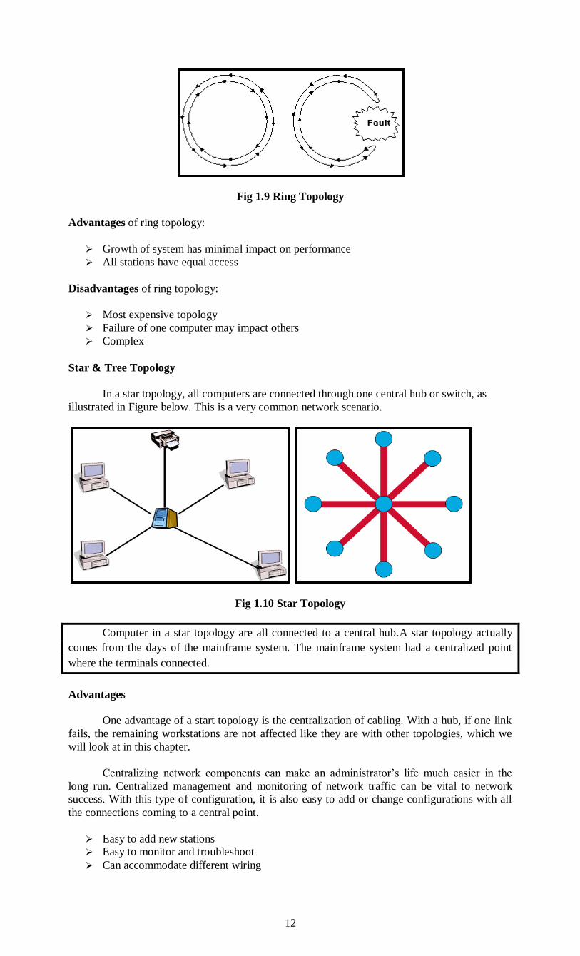
A counterrotating ring is a ring topology that consists of two rings transmitting in opposite
directions. The intent is to provide fault tolerance in the form of redundancy in the event of a
cable failure. If one ring goes, the data can flow across to the other path, thereby preserving the
ring.
12
Fig 1.9 Ring Topology
Advantages of ring topology:
Growth of system has minimal impact on performance
All stations have equal access
Disadvantages of ring topology:
Most expensive topology
Failure of one computer may impact others
Complex
Star & Tree Topology
In a star topology, all computers are connected through one central hub or switch, as
illustrated in Figure below. This is a very common network scenario.
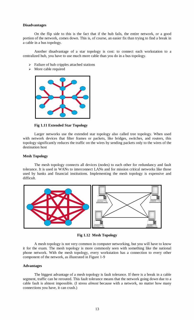
Fig 1.10 Star Topology
Computer in a star topology are all connected to a central hub.A star topology actually
comes from the days of the mainframe system. The mainframe system had a centralized point
where the terminals connected.
Advantages
One advantage of a start topology is the centralization of cabling. With a hub, if one link
fails, the remaining workstations are not affected like they are with other topologies, which we
will look at in this chapter.
Centralizing network components can make an administrator’s life much easier in the
long run. Centralized management and monitoring of network traffic can be vital to network
success. With this type of configuration, it is also easy to add or change configurations with all
the connections coming to a central point.
Easy to add new stations
Easy to monitor and troubleshoot
Can accommodate different wiring
13
Disadvantages
On the flip side to this is the fact that if the hub fails, the entire network, or a good
portion of the network, comes down. This is, of course, an easier fix than trying to find a break in
a cable in a bus topology.
Another disadvantage of a star topology is cost: to connect each workstation to a
centralized hub, you have to use much more cable than you do in a bus topology.
Failure of hub cripples attached stations
More cable required
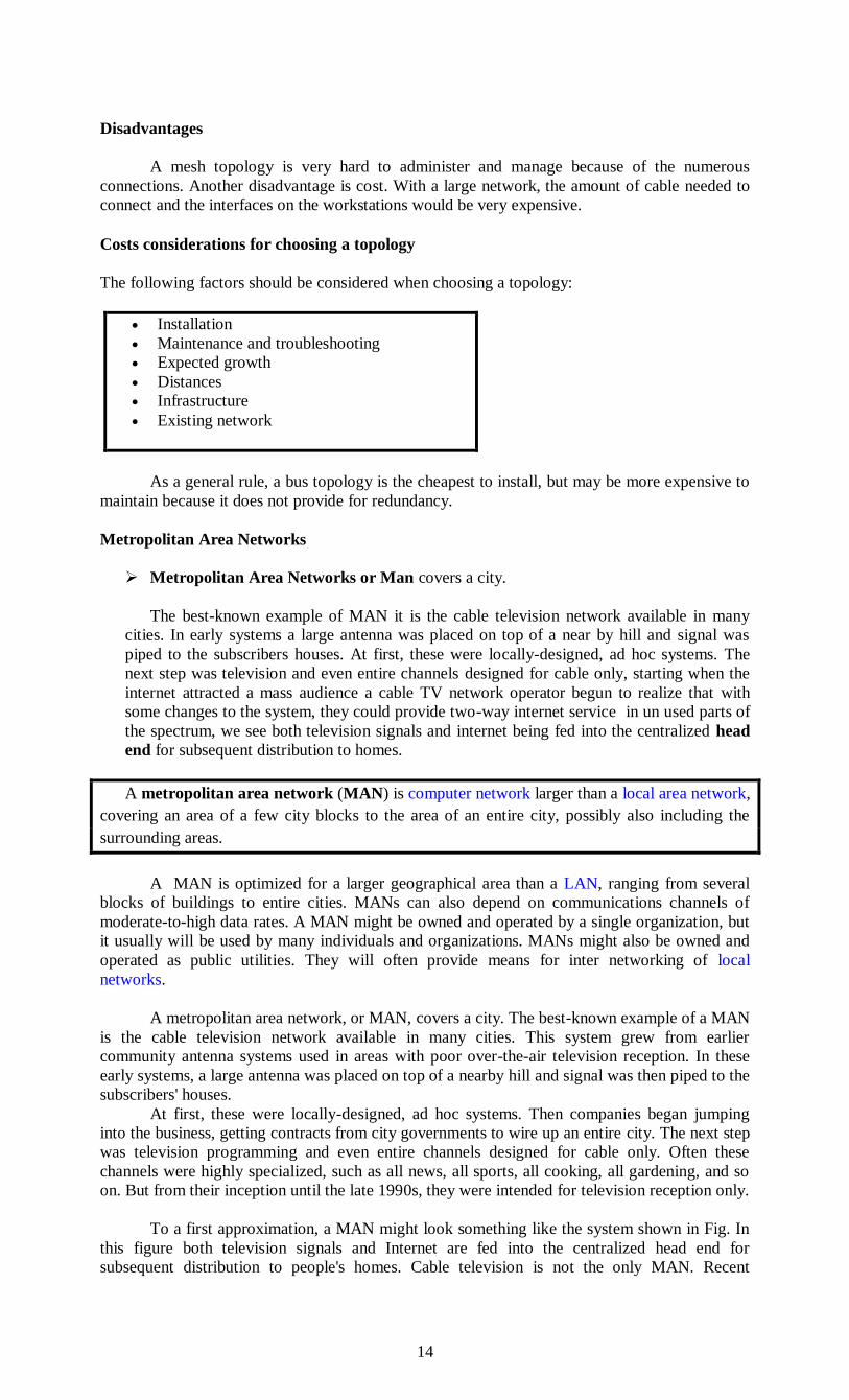
Fig 1.11 Extended Star Topology
Larger networks use the extended star topology also called tree topology. When used
with network devices that filter frames or packets, like bridges, switches, and routers, this
topology significantly reduces the traffic on the wires by sending packets only to the wires of the
destination host
Mesh Topology
The mesh topology connects all devices (nodes) to each other for redundancy and fault
tolerance. It is used in WANs to interconnect LANs and for mission critical networks like those
used by banks and financial institutions. Implementing the mesh topology is expensive and
difficult.
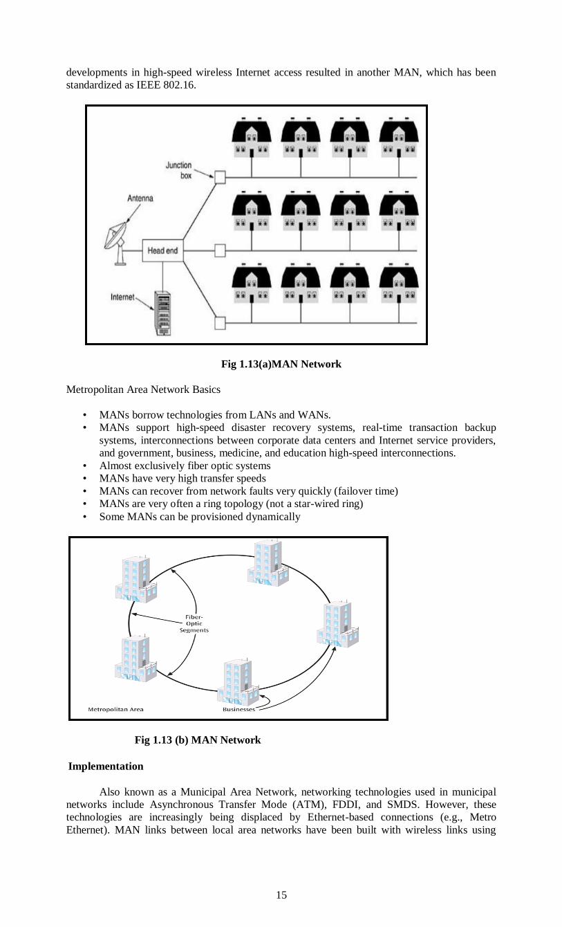
Fig 1.12 Mesh Topology
A mesh topology is not very common in computer networking, but you will have to know
it for the exam. The mesh topology is more commonly seen with something like the national
phone network. With the mesh topology, every workstation has a connection to every other
component of the network, as illustrated in Figure 1-9
Advantages
The biggest advantage of a mesh topology is fault tolerance. If there is a break in a cable
segment, traffic can be rerouted. This fault tolerance means that the network going down due to a
cable fault is almost impossible. (I stress almost because with a network, no matter how many
connections you have, it can crash.)
14
Disadvantages
A mesh topology is very hard to administer and manage because of the numerous
connections. Another disadvantage is cost. With a large network, the amount of cable needed to
connect and the interfaces on the workstations would be very expensive.
Costs considerations for choosing a topology
The following factors should be considered when choosing a topology:
Installation
Maintenance and troubleshooting
Expected growth
Distances
Infrastructure
Existing network
As a general rule, a bus topology is the cheapest to install, but may be more expensive to
maintain because it does not provide for redundancy.
Metropolitan Area Networks
Metropolitan Area Networks or Man covers a city.
The best-known example of MAN it is the cable television network available in many
cities. In early systems a large antenna was placed on top of a near by hill and signal was
piped to the subscribers houses. At first, these were locally-designed, ad hoc systems. The
next step was television and even entire channels designed for cable only, starting when the
internet attracted a mass audience a cable TV network operator begun to realize that with
some changes to the system, they could provide two-way internet service in un used parts of
the spectrum, we see both television signals and internet being fed into the centralized head
end for subsequent distribution to homes.
A metropolitan area network (MAN) is computer network larger than a local area network,
covering an area of a few city blocks to the area of an entire city, possibly also including the
surrounding areas.
A MAN is optimized for a larger geographical area than a LAN, ranging from several
blocks of buildings to entire cities. MANs can also depend on communications channels of
moderate-to-high data rates. A MAN might be owned and operated by a single organization, but
it usually will be used by many individuals and organizations. MANs might also be owned and
operated as public utilities. They will often provide means for inter networking of local
networks.
A metropolitan area network, or MAN, covers a city. The best-known example of a MAN
is the cable television network available in many cities. This system grew from earlier
community antenna systems used in areas with poor over-the-air television reception. In these
early systems, a large antenna was placed on top of a nearby hill and signal was then piped to the
subscribers' houses.
At first, these were locally-designed, ad hoc systems. Then companies began jumping
into the business, getting contracts from city governments to wire up an entire city. The next step
was television programming and even entire channels designed for cable only. Often these
channels were highly specialized, such as all news, all sports, all cooking, all gardening, and so
on. But from their inception until the late 1990s, they were intended for television reception only.
To a first approximation, a MAN might look something like the system shown in Fig. In
this figure both television signals and Internet are fed into the centralized head end for
subsequent distribution to people's homes. Cable television is not the only MAN. Recent
15
developments in high-speed wireless Internet access resulted in another MAN, which has been
standardized as IEEE 802.16.
Fig 1.13(a)MAN Network
Metropolitan Area Network Basics
• MANs borrow technologies from LANs and WANs.
• MANs support high-speed disaster recovery systems, real-time transaction backup
systems, interconnections between corporate data centers and Internet service providers,
and government, business, medicine, and education high-speed interconnections.
• Almost exclusively fiber optic systems
• MANs have very high transfer speeds
• MANs can recover from network faults very quickly (failover time)
• MANs are very often a ring topology (not a star-wired ring)
• Some MANs can be provisioned dynamically
Fig 1.13 (b) MAN Network
Implementation
Also known as a Municipal Area Network, networking technologies used in municipal
networks include Asynchronous Transfer Mode (ATM), FDDI, and SMDS. However, these
technologies are increasingly being displaced by Ethernet-based connections (e.g., Metro
Ethernet). MAN links between local area networks have been built with wireless links using
16
either microwave, radio, or infra-red laser transmission. Most companies rent or lease circuits
from common carriers because laying long stretches of cable is expensive.
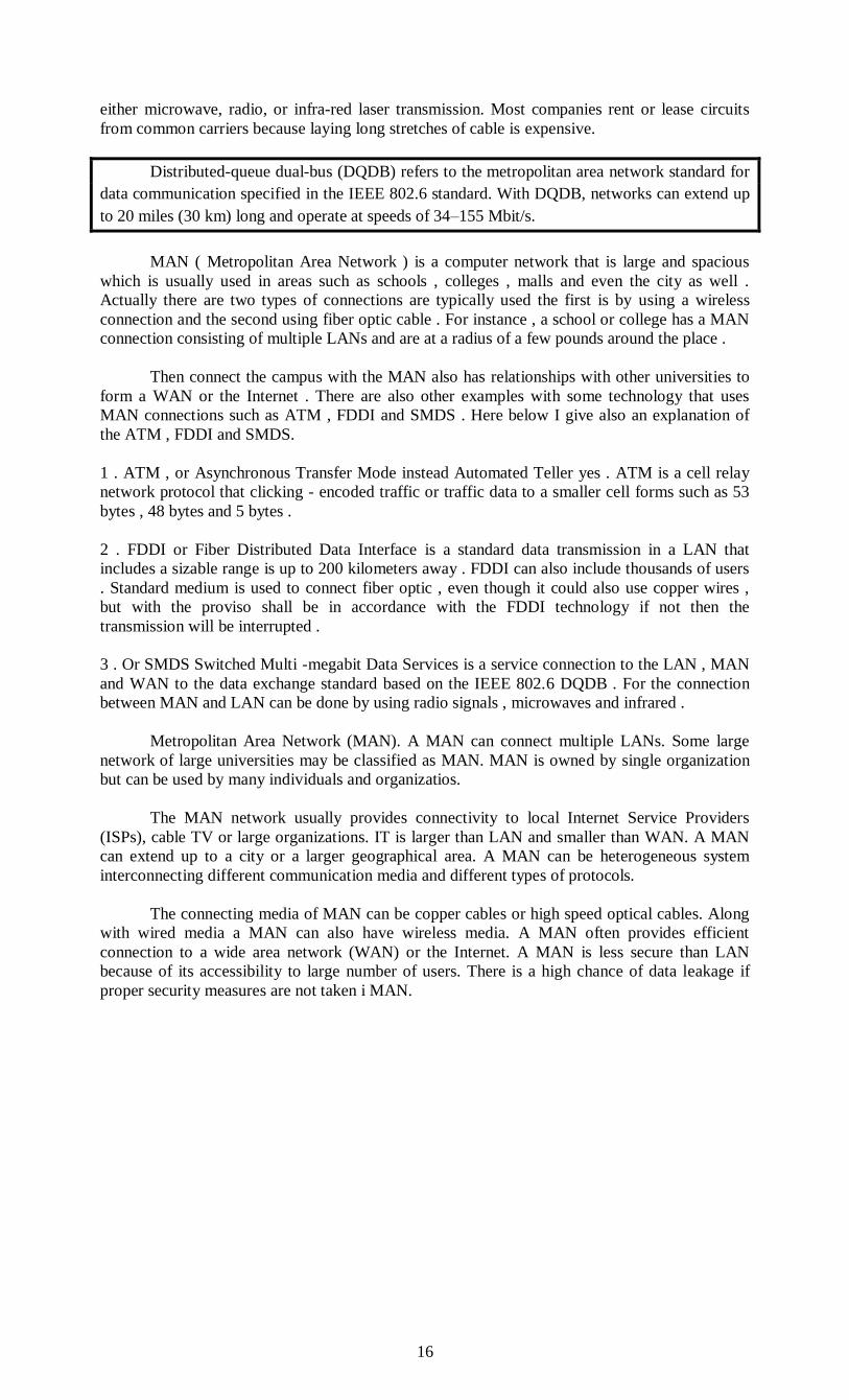
Distributed-queue dual-bus (DQDB) refers to the metropolitan area network standard for
data communication specified in the IEEE 802.6 standard. With DQDB, networks can extend up
to 20 miles (30 km) long and operate at speeds of 34–155 Mbit/s.
MAN ( Metropolitan Area Network ) is a computer network that is large and spacious
which is usually used in areas such as schools , colleges , malls and even the city as well .
Actually there are two types of connections are typically used the first is by using a wireless
connection and the second using fiber optic cable . For instance , a school or college has a MAN
connection consisting of multiple LANs and are at a radius of a few pounds around the place .
Then connect the campus with the MAN also has relationships with other universities to
form a WAN or the Internet . There are also other examples with some technology that uses
MAN connections such as ATM , FDDI and SMDS . Here below I give also an explanation of
the ATM , FDDI and SMDS.
1 . ATM , or Asynchronous Transfer Mode instead Automated Teller yes . ATM is a cell relay
network protocol that clicking - encoded traffic or traffic data to a smaller cell forms such as 53
bytes , 48 bytes and 5 bytes .
2 . FDDI or Fiber Distributed Data Interface is a standard data transmission in a LAN that
includes a sizable range is up to 200 kilometers away . FDDI can also include thousands of users
. Standard medium is used to connect fiber optic , even though it could also use copper wires ,
but with the proviso shall be in accordance with the FDDI technology if not then the
transmission will be interrupted .
3 . Or SMDS Switched Multi -megabit Data Services is a service connection to the LAN , MAN
and WAN to the data exchange standard based on the IEEE 802.6 DQDB . For the connection
between MAN and LAN can be done by using radio signals , microwaves and infrared .
Metropolitan Area Network (MAN). A MAN can connect multiple LANs. Some large
network of large universities may be classified as MAN. MAN is owned by single organization
but can be used by many individuals and organizatios.
The MAN network usually provides connectivity to local Internet Service Providers
(ISPs), cable TV or large organizations. IT is larger than LAN and smaller than WAN. A MAN
can extend up to a city or a larger geographical area. A MAN can be heterogeneous system
interconnecting different communication media and different types of protocols.
The connecting media of MAN can be copper cables or high speed optical cables. Along
with wired media a MAN can also have wireless media. A MAN often provides efficient
connection to a wide area network (WAN) or the Internet. A MAN is less secure than LAN
because of its accessibility to large number of users. There is a high chance of data leakage if
proper security measures are not taken i MAN.
17
Fig 1.14 MAN Network
When the computer network increases beyond local area network then it is called
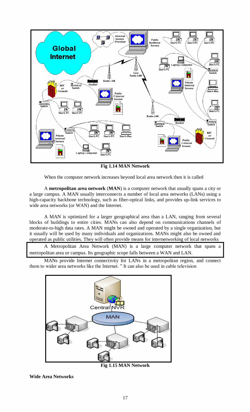
A metropolitan area network (MAN) is a computer network that usually spans a city or
a large campus. A MAN usually interconnects a number of local area networks (LANs) using a
high-capacity backbone technology, such as fiber-optical links, and provides up-link services to
wide area networks (or WAN) and the Internet.
A MAN is optimized for a larger geographical area than a LAN, ranging from several
blocks of buildings to entire cities. MANs can also depend on communications channels of
moderate-to-high data rates. A MAN might be owned and operated by a single organization, but
it usually will be used by many individuals and organizations. MANs might also be owned and
operated as public utilities. They will often provide means for internetworking of local networks
A Metropolitan Area Network (MAN) is a large computer network that spans a
metropolitan area or campus. Its geographic scope falls between a WAN and LAN.
MANs provide Internet connectivity for LANs in a metropolitan region, and connect
them to wider area networks like the Internet. ” It can also be used in cable television
Fig 1.15 MAN Network
Wide Area Networks
18
Wide Area Networks or WAN spans a large geographical area often a country or continent.
It contains collections of machines for running user programs called Hosts.
The hosts are connected by a communication subnet.
The hosts are owned by the customers whereas the communication subnet owned and
operated by Telephone Company or ISP.
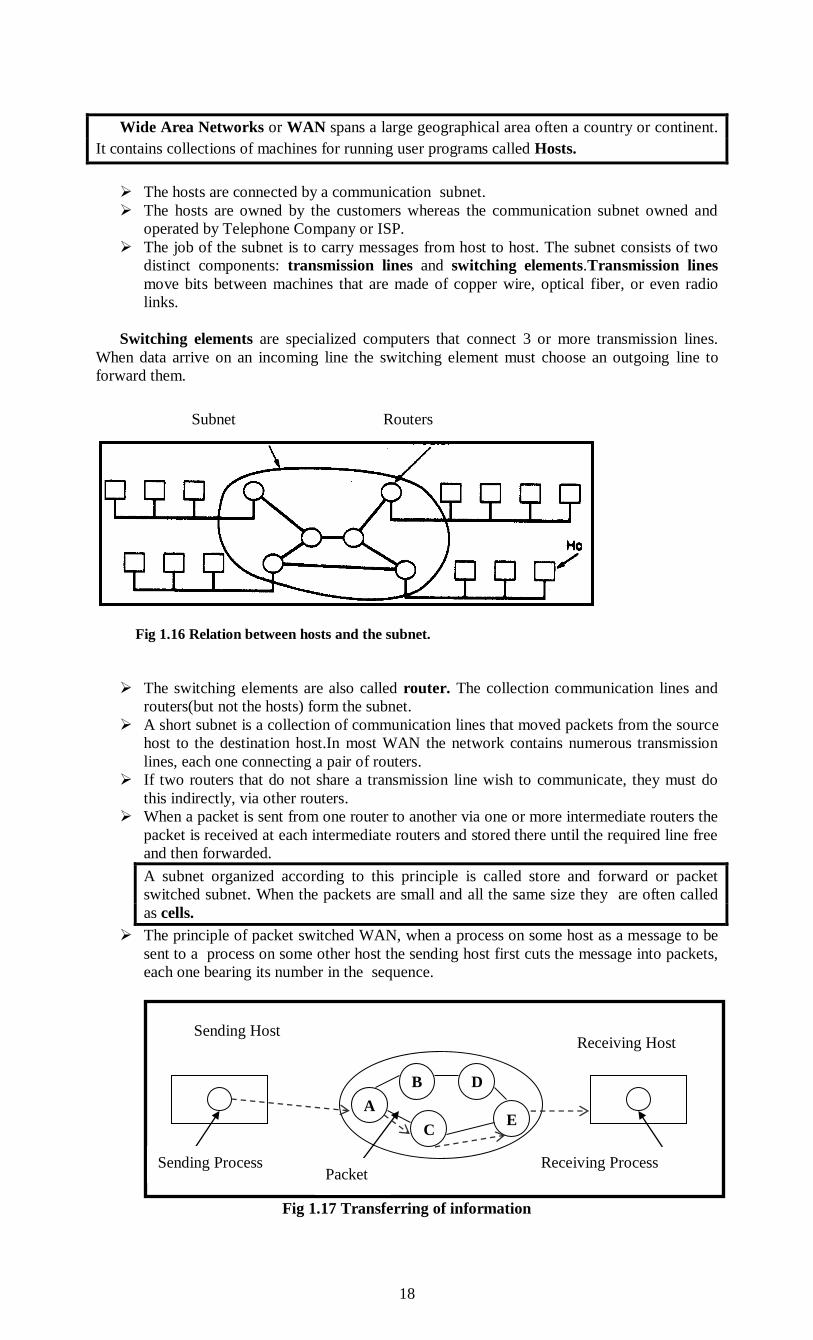
The job of the subnet is to carry messages from host to host. The subnet consists of two
distinct components: transmission lines and switching elements.Transmission lines
move bits between machines that are made of copper wire, optical fiber, or even radio
links.
Switching elements are specialized computers that connect 3 or more transmission lines.
When data arrive on an incoming line the switching element must choose an outgoing line to
forward them.
The switching elements are also called router. The collection communication lines and
routers(but not the hosts) form the subnet.
A short subnet is a collection of communication lines that moved packets from the source
host to the destination host.In most WAN the network contains numerous transmission
lines, each one connecting a pair of routers.
If two routers that do not share a transmission line wish to communicate, they must do
this indirectly, via other routers.
When a packet is sent from one router to another via one or more intermediate routers the
packet is received at each intermediate routers and stored there until the required line free
and then forwarded.
A subnet organized according to this principle is called store and forward or packet
switched subnet. When the packets are small and all the same size they are often called
as cells.
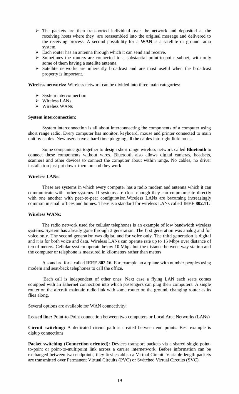
The principle of packet switched WAN, when a process on some host as a message to be
sent to a process on some other host the sending host first cuts the message into packets,
each one bearing its number in the sequence.
Fig 1.17 Transferring of information
A
B
A
D
C E
Sending Process
Sending Host
Receiving Process Packet
Receiving Host
Subnet Routers
Fig 1.16 Relation between hosts and the subnet.
19
The packets are then transported individual over the network and deposited at the
receiving hosts where they are reassembled into the original message and delivered to
the receiving process. A second possibility for a WAN is a satellite or ground radio
system.
Each router has an antenna through which it can send and receive.
Sometimes the routers are connected to a substantial point-to-point subnet, with only
some of them having a satellite antenna.
Satellite networks are inherently broadcast and are most useful when the broadcast
property is important.
Wireless networks: Wireless network can be divided into three main categories:
System interconnection
Wireless LANs
Wireless WANs
System interconnection:
System interconnection is all about interconnecting the components of a computer using
short range radio. Every computer has monitor, keyboard, mouse and printer connected to main
unit by cables. New users have a hard time plugging all the cables into right little holes.
Some companies got together to design short range wireless network called Bluetooth to
connect these components without wires. Bluetooth also allows digital cameras, headsets,
scanners and other devices to connect the computer about within range. No cables, no driver
installation just put down them on and they work.
Wireless LANs:
These are systems in which every computer has a radio modem and antenna which it can
communicate with other systems. If systems are close enough they can communicate directly
with one another with peer-to-peer configuration.Wireless LANs are becoming increasingly
common in small offices and homes. There is a standard for wireless LANs called IEEE 802.11.
Wireless WANs:
The radio network used for cellular telephones is an example of low bandwidth wireless
systems. System has already gone through 3 generation. The first generation was analog and for
voice only. The second generation was digital and for voice only. The third generation is digital
and it is for both voice and data. Wireless LANs can operate rate up to 15 Mbps over distance of
ten of meters. Cellular system operate below 10 Mbps but the distance between way station and
the computer or telephone is measured in kilometers rather than meters.
A standard for a called IEEE 802.16. For example an airplane with number peoples using
modem and seat-back telephones to call the office.
Each call is independent of other ones. Next case a flying LAN each seats comes
equipped with an Ethernet connection into which passengers can plug their computers. A single
router on the aircraft maintain radio link with some router on the ground, changing router as its
flies along.
Several options are available for WAN connectivity:
Leased line: Point-to-Point connection between two computers or Local Area Networks (LANs)
Circuit switching: A dedicated circuit path is created between end points. Best example is
dialup connections
Packet switching (Connection oriented): Devices transport packets via a shared single point-
to-point or point-to-multipoint link across a carrier internetwork. Before information can be
exchanged between two endpoints, they first establish a Virtual Circuit. Variable length packets
are transmitted over Permanent Virtual Circuits (PVC) or Switched Virtual Circuits (SVC)
20
Packet switching (Connectionless): Devices transport packets via a shared single point-to-point
or point-to-multipoint link across a carrier internetwork. Variable length packets are transmitted.
Between endpoints no connection is build; endpoints can just offer packets to the network,
addressed to any other endpoint and the network will try to deliver the packet. As an example:
the Internet works this way.
Cell relay:Similar to packet switching, but uses fixed length cells instead of variable length
packets. Data is divided into fixed-length cells and then transported across virtual circuits
Home network:
Home network is on the horizon. The fundamental idea is that in the future most homes
will be setup for networking. Every device in home will be capable of communicating with every
other device, and all of them will be accessible over the internet. Many devices are capable of
being a network some of more obvious categories are as follows:
Computers ( desktop PC, notebook PC, PDA, shared peripherals)
Entertainment ( TV, DVD, VCR, Camcorder, camera, stereo, MP3)
Telecommunication ( telephone, mobile telephone, intercom, fax)
Appliances ( microwave, refrigerator, clock, furnace, airco, lights)
Telemetry ( utility meter, smoke/burglar alarm, thermostat, babycam)
A home network or home area network (HAN) is a type of local area network that
develops from the need to facilitate communication and interoperability among digital devices
present inside or within the close vicinity of a home.
Devices capable of participating in this network–smart devices such as network printers
and handheld mobile computers–often gain enhanced emergent capabilities through their ability
to interact. These additional capabilities can then be used to increase the quality of life inside the
home in a variety of ways, such as automation of repetitious tasks, increased personal
productivity, enhanced home security, and easier access to entertainment.
Infrastructure
A home network usually relies on one of the following equipment to establish physical
layer, data link layer, and network layer connectivity both internally amongst devices and
externally with outside networks:
A modem is usually provided by an ISP to expose an Ethernet interface to the WAN via
their telecommunications infrastructure. In homes these usually come in the form of a
DSL modem or cable modem.
A router manages network layer connectivity between a WAN and the HAN. Most home
networks feature a particular class of small, passively-cooled, table-top device with an
integrated wireless access point and 4 port Ethernet switch. These devices aim to make
the installation, configuration, and management of a home network as automated, user
friendly, and "plug-and-play" as possible.
A network switch is used to allow devices on the home network to talk to one another via
Ethernet. While the needs of most home networks are satisfied with Wi-Fi or the built-in
switching capacity of their router, certain situations require the introduction of a distinct
switch. For example:
o When the router's switching capacity is exceeded. Most home routers expose only
4 to 6 Ethernet ports.
o When Power over Ethernet is required by devices such as IP cameras and IP
phones
o When distant rooms have a large amount of wired devices in close proximity
A wireless access point is required for connecting wireless devices to a network. Most
home networks rely on one "Wireless Router" combination device to fill this role.
A network bridge connecting two network interfaces to each other, often in order to grant
a wired-only device, e.g. Xbox, access to a wireless network medium.
21
A home network is a group of devices – such as computers, game systems, printers, and mobile
devices – that connect to the Internet and each other. Home networks connect in two ways:
1.A wired network, which connects devices like printers and scanners with cables.
2.A wireless network, which connects devices like tablets and e-readers without cables
Set Up a Home Network
There are many reasons to establish a home network. Here are just a few of the things
home networking allows you to do:
Connect to the Internet from multiple computers, game systems, mobile devices, and
more.
Access files and folders on all devices connected to the network.
Print from multiple computers on a single printer.
Manage security settings for all networked devices in one place.
Need to Set Up a Home Network
To set up home networking, need the following:
XFINITY Internet Service subscription (or subscription to another Internet provider)
A modem, which connects to the Internet, and a router, which connects your devices to
each other and to the Internet through your modem (or a gateway, which functions as
both a modem and a router)
A computer or other device to connect to the network
The Wireless Gateway 1 (model numbers TG852G, TG862G, SMCD3GNV, TC8305C)
and Wireless Gateway 2 (model number DPC3939) function as an all-in-one modem, router, and
phone device. They automatically provide users with the best security settings available for a
home network. Find out more about wireless gateways.
Wireless Home Network
A wireless network, often called Wi-Fi, connects devices to each other and to the Internet
without using cables. Read our rundown of wireless networking and its benefits.
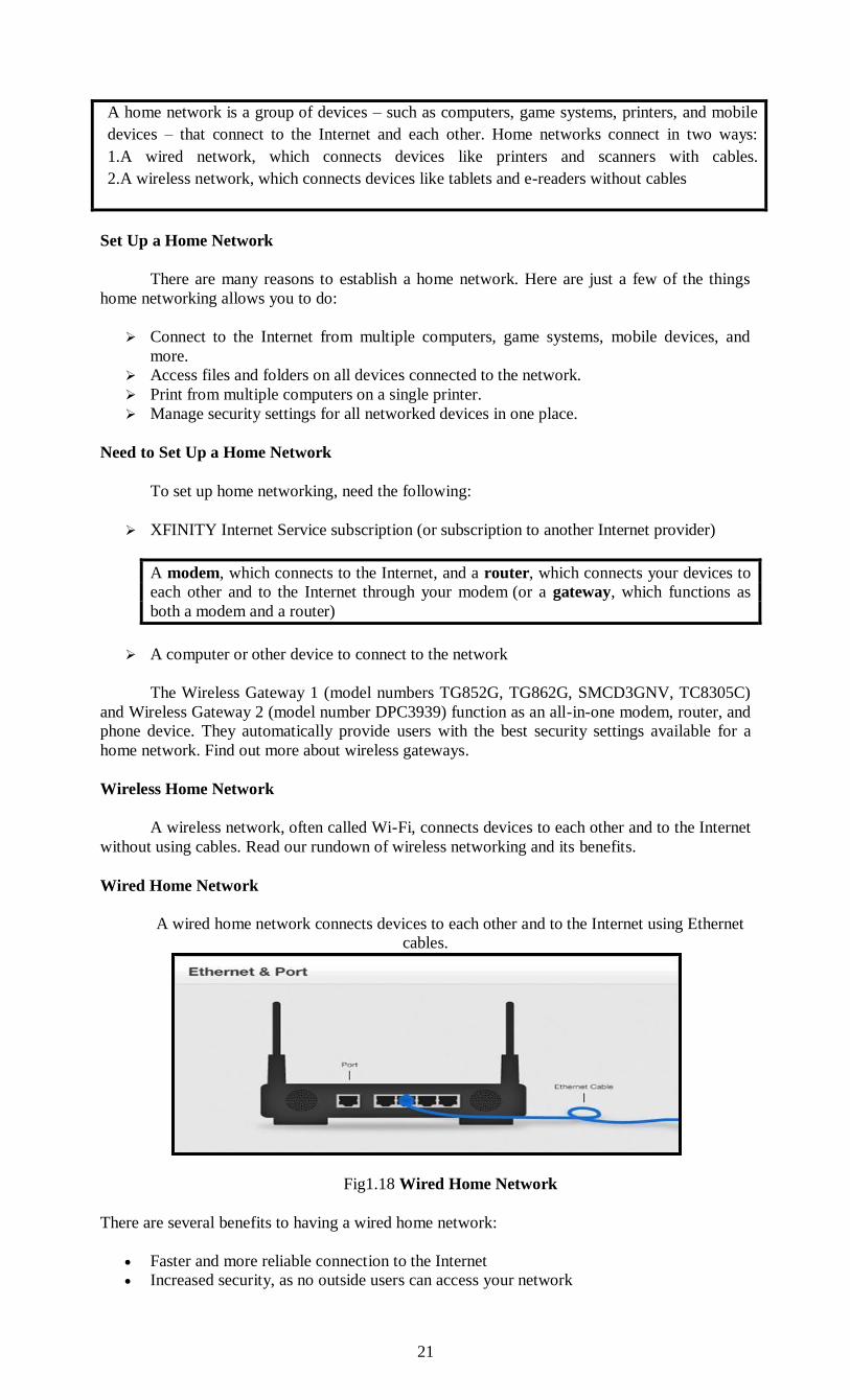
Wired Home Network
A wired home network connects devices to each other and to the Internet using Ethernet
cables.
Fig1.18 Wired Home Network
There are several benefits to having a wired home network:
Faster and more reliable connection to the Internet
Increased security, as no outside users can access your network

22
Easier set-up and troubleshooting than wireless connections
Mixed Home Network
Many people find that a mix of wireless and wired networking meets their needs best. For
instance, devices that stream movies benefit from the quicker and more stable wired connection.
Devices like laptops or tablets, however, benefit from the mobility available with a wireless
connection.
Both the Wireless Gateway 1 and Wireless Gateway 2 come with wireless capability and
four Ethernet ports, allowing you to connect devices with and without cables at the same time.
Internetworks:
A collection of interconnected networks called internetwork or internet. A common form
of internet is a collection of LANs connected by WANs. Subnet makes the most sense in the
context of wide area network, Where it refers to collection of routers to the communication lines
owned by network operator. Telephone system consist of telephone switching offices connected
to one another by high speed lines and houses and businesses by low speed lines.
Lines and equipment owned by telephone companies form the subnet of telephone
system. The combination of a subnet and its host forms a network. An internetwork is formed
when distinct network are interconnected.
A Brief History
A network is a group of connected communicating devices such as computers and
printers. An internet (note the lowercase letter i) is two or more networks that can communicate
with each other. The most notable internet is called the Internet (uppercase letter I), a
collaboration of more than hundreds of thousands of interconnected networks. Private
individuals as well as various organizations such as government agencies, schools, research
facilities, corporations, and libraries in more than 100 countries use the Internet. Millions of
people are users.
Yet this extraordinary communication system only came into being in 1969. In the mid-
1960s, mainframe computers in research organizations were standalone devices. Computers from
different manufacturers were unable to communicate with one another. The Advanced Research
Projects Agency (ARPA) in the Department of Defense (DoD) was interested in finding a way to
connect computers so that the researchers they funded could share their findings, thereby
reducing costs and eliminating duplication of effort.
In 1967, at an Association for Computing Machinery (ACM) meeting, ARPA presented
its ideas for ARPANET, a small network of connected computers. The idea was that each host
computer (not necessarily from the same manufacturer) would be attached to a specialized
computer, called an inteiface message processor (IMP). The IMPs, in tum, would be connected
to one another. Each IMP had to be able to communicate with other IMPs as well as with its own
attached host. By 1969, ARPANET was a reality. Four nodes, at the University of California at
Los Angeles (UCLA), the University of California at Santa Barbara (UCSB), Stanford Research
Institute (SRI), and the University of Utah, were connected via the IMPs to form a network.
Software called the Network Control Protocol (NCP) provided communication between the
hosts.
In 1972, Vint Cerf and Bob Kahn, both of whom were part of the core ARPANET group,
collaborated on what they called the Internetting Project1.
Cerf and Kahn's landmark 1973 paper outlined the protocols to achieve end-to-end
delivery of packets. This paper on Transmission Control Protocol (TCP) included concepts such
as encapsulation, the datagram, and the functions of a gateway. Shortly thereafter, authorities
made a decision to split TCP into two protocols: Transmission Control Protocol (TCP) and
Internetworking Protocol (lP). IP would handle datagram routing while TCP would be
responsible for higher-level functions such as segmentation, reassembly, and error detection. The
internetworking protocol became known as TCPIIP.
The Internet Today
23
The Internet has come a long way since the 1960s. The Internet today is not a simple
hierarchical structure. It is made up of many wide- and local-area networks joined by connecting
devices and switching stations. It is difficult to give an accurate representation of the Internet
because it is continually changing-new networks are being added, existing networks are adding
addresses, and networks of defunct companies are being removed. Today most end users who
want Internet connection use the services of Internet service providers (lSPs). There are
international service providers, national service providers, regional service providers, and local
service providers. The Internet today is run by private companies, not the government.
International Internet Service Providers:
At the top of the hierarchy are the international service providers that connect nations
together.
National Internet Service Providers:
The national Internet service providers are backbone networks created and maintained by
specialized companies. There are many national ISPs operating in North America; some of the
most well known are SprintLink, PSINet, UUNet Technology, AGIS, and internet Mel. To
provide connectivity between the end users, these backbone networks are connected by complex
switching stations (normally run by a third party) called network access points (NAPs). Some
national ISP networks are also connected to one another by private switching stations called
peering points. These normally operate at a high data rate (up to 600 Mbps).
Regional Internet Service Providers:
Regional internet service providers or regional ISPs are smaller ISPs that are connected
to one or more national ISPs. They are at the third level of the hierarchy with a smaller data rate.
Local Internet Service Providers:
Local Internet service providers provide direct service to the end users. The local ISPs
can be connected to regional ISPs or directly to national ISPs. Most end users are connected to
the local ISPs. Note that in this sense, a local ISP can be a company that just provides Internet
services, a corporation with a network that supplies services to its own employees, or a nonprofit
organization, such as a college or a university, that runs its own network. Each of these local
ISPs can be connected to a regional or national service provider.
Protocols:
In computer networks, communication occurs between entities in different systems. An
entity is anything capable of sending or receiving information. However, two entities cannot
simply send bit streams to each other and expect to be understood. For communication to occur,
the entities must agree on a protocol. A protocol is a set of rules that govern data
communications. A protocol defines what is communicated, how it is communicated, and when
it is communicated.
The key elements of a protocol are syntax, semantics, and timing.
Syntax. The term syntax refers to the structure or format of the data, meaning the order in
which they are presented. For example, a simple protocol might expect the first 8 bits of
data to be the address of the sender, the second 8 bits to be the address of the receiver,
and the rest of the stream to be the message itself.
Semantics. The word semantics refers to the meaning of each section of bits. How is a
particular pattern to be interpreted, and what action is to be taken based on that
interpretation? For example, does an address identify the route to be taken or the final
destination of the message?
Timing. The term timing refers to two characteristics: when data should be sent and how
fast they can be sent. For example, if a sender produces data at 100 Mbps but the receiver
can process data at only 1 Mbps, the transmission will overload the receiver and some
data will be lost.
Standards Standards are essential in creating and maintaining an open and competitive market for
equipment manufacturers and in guaranteeing national and international interoperability of data
and telecommunications technology and processes. Standards provide guidelines to

24
manufacturers, vendors, government agencies, and other service providers to ensure the kind of
interconnectivity necessary in today's marketplace and in international communications.
Data communication standards fall into two categories: de facto (meaning "by fact" or
"by convention") and de jure (meaning "by law" or "by regulation").
De facto. Standards that have not been approved by an organized body but have been
adopted as standards through widespread use are de facto standards. De facto standards
are often established originally by manufacturers who seek to define the functionality of a
new product or technology.
De jure. Those standards that have been legislated by an officially recognized body are de
jure standards.
Layered Tasks:
We use the concept of layers in our daily life. As an example, let us consider two friends
who communicate through postal maiL The process of sending a letter to a friend would be
complex if there were no services available from the post office. Below Figure shows the steps in
this task.
Sender, Receiver, and Carrier
In Figure we have a sender, a receiver, and a carrier that transports the letter. There is a
hierarchy of tasks.
At the Sender Site
Let us first describe, in order, the activities that take place at the sender site.
Higher layer. The sender writes the letter, inserts the letter in an envelope, writes the
sender and receiver addresses, and drops the letter in a mailbox.
Middle layer. The letter is picked up by a letter carrier and delivered to the post office.
Lower layer. The letter is sorted at the post office; a carrier transports the letter.
0n the Way: The letter is then on its way to the recipient. On the way to the recipient's local post
office, the letter may actually go through a central office. In addition, it may be transported by
truck, train, airplane, boat, or a combination of these.
Fig 1.19 (a) Layere working Concept

25
At the Receiver Site
Lower layer. The carrier transports the letter to the post office.
Middle layer. The letter is sorted and delivered to the recipient's mailbox.
Higher layer. The receiver picks up the letter, opens the envelope, and reads it.
NETWORK SOFTWARE
The first computer networks were designed with the hardware as the main concern and the
software as an afterthought. Network software is now highly structured. Protocol Hierarchies To
reduce their design complexity, most networks are organized as a series of layers or levels, each
one built upon the one below it. The number of layers, the name of each layer, the contents of
each layer, and the function of each 1ayer differ from network to network.
However, in all networks, the purpose of each layer is to offer certain services to the higher
layers, shielding those layers from the details of how the offered services are actually
implemented. Layer n on one machine carries on a conversation with layer n on another
machine.
The rules and conventions used in this conversation are collectively known as the layer n
protocol.
Basically, a protocol is an agreement between the communicating parties on how
communication is to proceed. Violating the protocol will make communication more difficult if
not impossible. The entities comprising the corresponding layers on different machines are called
peers. The peers communicate using protocol.
In reality, no data are directly transferred from layer n on one machine to layer n on
another machine. Instead, each layer passes data and control information to the layer
immediately below it, until the lowest layer is reached. Below layer 1 is the physical medium
through which actual communication occurs Between each pair of adjacent layers there is an
interface. The interface defines which primitive operations and services the lower layer offers to
the upper one. One of the most important considerations is defining clean interfaces between the
layers.
Doing so, in turn, requires that each layer perform a specific collection of well-understood
functions. In addition to minimizing the amount of information that must be passed between
layers, clean-cut interfaces also make it simpler to replace the implementation of one layer with a
completely different implementation because all that is required of the new implementation is
that it offers exactly the same set of services to its upstairs neighbor as the old implementation
did.
A set of layers and protocols is called network architecture. The specification of
architecture contains enough information to build the hardware/software for each layer so that it
correctly obeys the appropriate protocol.
A list of protocols used by a certain system, one protocol per layer, is called a protocol
stack. A message M, produced by the application process puts a header in front of the message to
identify the message and passes the result to the next layer. The header includes control
information, such as a sequence numbers to allow the next layer in the destination machine to
deliver messages in the right order. Headers may also contain sizes, times and other control
fields. The layers break up the incoming messages into smaller units, packets.
For example, message M is split into two parts, m1 and m2. A Layer decides which of the
outgoing lines to use and passes the packets to next layer. This Layer adds not only a header to
each piece, but also a trailer, and give the resulting unit to layer below it for physical

26
transmission. At the receiving machine the message moves upward, from layer to layer, with
headers being stripped off as it progresses.
Fig 1.19 Layers Hierarchies
None of the headers for layers below n are passed up to layer n. The peer process
abstraction is crucial to all network design. Using it, the unmanageable task of designing the
complete network can be broken into several smaller, manageable, design problems, namely the
design of the individual layers.
Design Issues for the Layers
Some of the key design issues that occur in computer networking are present in several
Layers. Every layer needs a mechanism for identifying senders and receivers. Since a network
normally has many computers, some of which have multiple processes, a means is needed for a
process on one machine to specify with whom it want to talk.
Layers, Protocols and Interfaces
Host 2
Layer 1/2 Interface
Layer 2/3 Interface
Layer 3/4 Interface
Layer 4/5 Interface
Layer 4 Protocol
Layer 3 Protocol
Layer 2 Protocol
Layer 1 Protocol
Layer 5 Protocol Host 1
Layer 5
Layer 2
Layer 1 Layer 1
Layer 2
Layer 3
Layer 4
Layer 5
Layer 3
Layer 4
Physical Medium
Layer 5 Protocol M M
H4 M H4 M
H3 H4 M1 H3 H4 M1 H3 M2 H3 M2
H2 H3 M2 T2 H2 H3 H4 M1 T2 H2 H3 M2 T2
Source Machine Destination Machine
Layer 4 Protocol
Layer 3 Protocol
Layer 2
Protocol H2 H3 H4 M1 T2
27
As a consequence of having multiple destinations, some form of addressing is needed in
order to specify a specific destination.
Another set of design decisions concerns the rules for data transfer. In some systems,
data only travel in one direction (simplex communication). In others they can travel in either
direction, but not simultaneously (half-duplex communication). In still others they travel in
both directions at once (full-duplex communication). The protocol must also determine how
many logical channels the connection corresponds to, and what their priorities are. Many
networks provide at least two logical channels per connection, one for normal data and one for
urgent data.
Error control is an important issue because physical communication circuits are not
perfect. Many error-detecting and error-correcting codes are known, but both ends of the
connection must agree on which one is being used. In addition the receiver must have some way
of telling the sender which messages have been correctly received and which has not. Not all
communication channels preserve the order of messages sent on them to deal with a possible loss
of sequencing; the protocol must make explicit provision for the receiver to allow the pieces to
be put back together properly.
An issue that occurs at every level is how to keep a fast sender from swamping a slow
receiver with data. Some of them involve some kind of feedback from the receiver to the
sender, either directly or indirectly, about the receiver's current situation. This subject is called
flow control.
Another problem that must be solved at several levels is the inability of all processes to
accept arbitrarily long messages. This property leads to mechanisms for disassembling,
transmitting, and then reassembling messages. A related issue is what to do when processes insist
upon transmitting data in units that are so small that sending each one separately is inefficient.
Here the solution is to gather together several small messages heading toward a common
destination into a single large message and dismember the large message at the other side. When
it is inconvenient or expensive to set up a separate connection for each pair of communicating
processes, the underlying layer may decide to use the same connection for multiple, unrelated
conversations.
As long as this multiplexing and de-multiplexing is done transparently, it can be used
by any layer. Multiplexing is needed in the physical layer, for example, where all the traffic for
all connections has to be sent over at most a few physical circuits. When there are multiple paths
between source and destination, a. route must be chosen. Sometimes this decision must be split
over two or more layers.
Connection-Oriented and Connectionless Services
Connection-Oriented and Connectionless Services Layers can offer two different types
of service to the layers above them:
1.Connection-oriented and
2.Connectionless.
Connection-oriented service is modeled after the telephone system. To talk to someone,
you pick up the phone, dial the number, talk, and then hang up. Similarly, to use a connection-
oriented network service, the service user first establishes a connection, uses the connection, and
then releases the connection. The essential aspect of a connection is that it acts like a tube: the
sender pushes objects (bits) in at one end, and the receiver takes them out in the same order at the
other end.
Connectionless service is modeled after the postal system. Each message carries the full
destination address, and each one is routed through the system independent of all the others.
Normally, when two messages are sent to the same destination, the first one sent will be the first
one to arrive. However, it is possible that the first one sent can be delayed so that the second one
arrives first. Each service can be characterized by a quality of service.

28
Some services are reliable in the sense that they never lose data. Usually, a reliable
service is implemented by having the receiver acknowledge the receipt of each message, so the
sender is sure that it arrived. The acknowledgement process introduces overhead and delays,
which are often worth it but are sometimes undesirable.
A typical situation in which a reliable connection-oriented service is appropriate is file
transfer. The owner of the file wants to be sure that all the bits arrive correctly and in the same
order they were sent. Reliable connection-oriented service has two minor variations: message
sequences and byte streams. In the former, the message boundaries are preserved when two 1-
KB messages are sent, they arrive as two distinct 1-KB messages never as one 2-KB message. In
the latter, the connection is simply a stream of bytes, with no message boundaries. Not all
applications require connections.
Unreliable (not acknowledged) connectionless service is often called datagram service,
which does not provide an acknowledgement back to the sender. In other situations, the
convenience of not having to establish a connection to send one short message is desired, but
reliability is essential.
The acknowledged datagram service can be provided for these applications. Still
another service is the request-reply service.
In this service, the sender transmits a single datagram containing a request, the reply
contains the answer. Request-reply is commonly used to implement communication in the client-
server model: the client issues a request and the server responds to it.
Service Primitives
A service is formally specified by a set of primitives (operations) available to a user or
other entity to access the service.
These primitives tell the service to perform some action or report on an action taken by a
peer entity.
One way to classify the service primitives is to divide them into four classes:
Primitive Meaning
LISTEN Block waiting for a incoming connection.
CONNECT Establish a connection with a waiting peer.
RECEIVE Block waiting for an incoming message.
SEND Send the message to the peer
DISCONNECT Terminate a connection
Five classes of service primitives.
First the server executes LISTEN to indicate that is prepared to accept the incoming
connection. A common way to implement LISTEN is make it a blocking system call. After
Connection Oriented
Connectionless
Six different types of Service

29
executing primitive a server process a block until a request for connection appears. A client
process executed CONNECT to establish a connection with the server.
The CONNECT call needs to specify who to connect to, parameter gives the servers
address.
The operating system sends the packet to the peer asking it to connect as shown by (1) fig
(refer class notes). The client process is connected until there is a response. When a packet
arrives at the server it is processed by the operating system. When a system sees the packet is
requesting a connection, it checks to see there is a listener. Unblock the listener and sends back
the acknowledgement (2).
The arrival of acknowledgement releases the client. At this point the client and server are
both are running and they have a connection established. Next step for the server to execute
RECEIVE to prepare to accept the first request.
The server does this immediately upon being released from the LISTEN, before the
acknowledgement can get back to the client. The RECEIVE call blocks the srever. The client
executes send to transmit the request (3) followed by the execution to receive to get the reply.
The arrival of the request packet at the server machine unblocks the server process so it can
process the request. After it has done the work it uses SEND to return the answer to the client
(4).
If it is done it use DISCONNECT to terminate the connection. An initial is a blocking
call, suspending the client and sending a packet to the server saying that connection is no longer
needed (5). When the server gets the packet it also issues a DISCONNECT of its own,
acknowledging the client and releasing the connection when the servers packet (6) gets back to
the client machine, the client process is released and connection is broken.
The Relationship of Services to Protocols
The service defines what operations the layer is prepared to perform or behalf of its users,
but it says nothing at all about how these operations are implemented. A service relates to an
interface between two layers, with the lower layer being the service provider and the upper layer
being the service user.
A service is a set of primitives (operations) that a layer provides to the layer above it. A
protocol, in contrast, is a set of rules governing the format and meaning of the frames, packets,
or messages that are exchanged by the peer entities within a layer.
Entities use protocols in order to implement their service definitions. They are free to
change their protocols at will, provided they do not change the service visible to their users. In
this way, the service and the protocol are completely decoupled.
A service is like an abstract data type or an object in an object-oriented language. It
defines operations that can be performed on an object but does not specify how these operations
are implemented. A protocol relates to the implementation of the service and as such is not
visible to the user of the service.
The OSI Reference Model
This model is based on a proposal developed by the International Standards Organization
(ISO) as a first step toward international standardization of the protocols used in the various
layers The model is called the ISO OSI (Open Systems Interconnection) Reference Model
because it deals with connecting open systems—that is, systems that are open for
communication with .
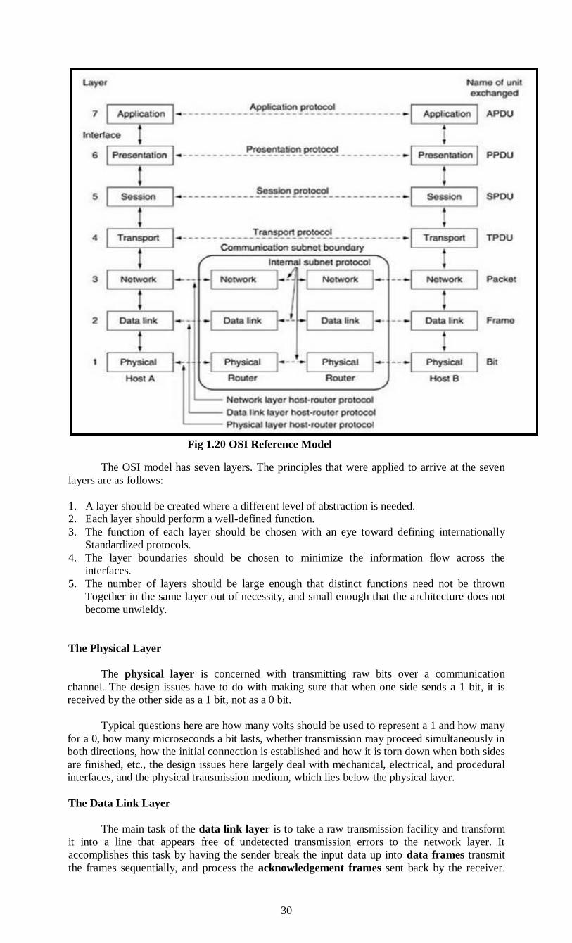
30
The OSI model has seven layers. The principles that were applied to arrive at the seven
layers are as follows:
1. A layer should be created where a different level of abstraction is needed.
2. Each layer should perform a well-defined function.
3. The function of each layer should be chosen with an eye toward defining internationally
Standardized protocols.
4. The layer boundaries should be chosen to minimize the information flow across the
interfaces.
5. The number of layers should be large enough that distinct functions need not be thrown
Together in the same layer out of necessity, and small enough that the architecture does not
become unwieldy.
The Physical Layer
The physical layer is concerned with transmitting raw bits over a communication
channel. The design issues have to do with making sure that when one side sends a 1 bit, it is
received by the other side as a 1 bit, not as a 0 bit.
Typical questions here are how many volts should be used to represent a 1 and how many
for a 0, how many microseconds a bit lasts, whether transmission may proceed simultaneously in
both directions, how the initial connection is established and how it is torn down when both sides
are finished, etc., the design issues here largely deal with mechanical, electrical, and procedural
interfaces, and the physical transmission medium, which lies below the physical layer.
The Data Link Layer
The main task of the data link layer is to take a raw transmission facility and transform
it into a line that appears free of undetected transmission errors to the network layer. It
accomplishes this task by having the sender break the input data up into data frames transmit
the frames sequentially, and process the acknowledgement frames sent back by the receiver.
Fig 1.20 OSI Reference Model

31
Since the physical layer merely accepts and transmits a stream of bits without any regard to
meaning or structure, it is up to the data link layer to create and recognize frame boundaries.
This can be accomplished by attaching special bit patterns to the beginning and end of the
frame. If these bit patterns can accidentally occur in the data, special care must be taken to make
sure these patterns are not incorrectly interpreted as frame delimiters. A noise burst on the line
can destroy a frame completely. In this case, the data link layer software on the source machine
can retransmit the frame.
However, multiple transmissions of the same frame introduce the possibility of duplicate
frames. A duplicate frame could be sent if the acknowledgement frame from the receiver back to
the sender were lost. It is up to this layer to solve the problems caused by damaged, lost, and
duplicate frames. The data link layer may offer several different service classes to the network
layer, each of a different quality and with a different price.
Another issue that arises in the data link layer is how to keep a fast transmitter from
drowning a slow receiver in data. Some traffic regulation mechanism must be employed to let
the transmitter know how much buffer space the receiver has at the moment. Frequently, this
flow regulation and the error handling are integrated. If the line can be used to transmit data in
both directions, this introduces a new complication that the data link layer software must deal
with. The problem is that the acknowledgement frames for A to B traffic compete for the use of
the line with data frames for the B to A traffic.
Broadcast networks have an additional issue in the data link layer: how, to control access
to the shared channel. A special sub layer of the data link layer, the medium access sublayer,
deals with this problem.
The Network Layer
The network layer is concerned with controlling the operation of the subnet. A key
design issue is determining how packets are routed from source to destination. Routes can be
based on static tables that are "wired into" the network and rarely changed. They can also be
determined at the start of each conversation, for example a terminal session. Finally, they can be
highly dynamic, being determined a new for each packet, to reflect the current network load.
If too many packets are present in the subnet at the same time, they will get in each
other's way forming bottlenecks. The control of such congestion also belongs to the network
layer. There should be software that must count how many packets or characters or bits are sent
by each customer. When a packet crosses between layers, with different rates on each side, the
accounting can become complicated.
When a packet has to travel from one network to another to get to its destination, many
problems can arise. The addressing used by the second network may be different from the first
one. The second one may not accept the packet because it is too large, the protocols may differ,
and so on. It is up to the network layer to overcome all these problems to allow heterogeneous
networks get interconnected. In broadcast networks, the routing problem is simple, so the
network layer often is thin or even nonexistent.
The Transport Layer
The basic function of the transport layer is to accept data from the session layer, split it
up into smaller units if needed, pass these to the network layer, and ensure that the pieces all
arrive correctly at the other end. Under normal conditions, the transport layer creates a distinct
network connection for each transport connection required by the session layer. If the transport
connection requires a high throughput, however, the transport layer might create multiple
network connections, dividing the data among the network connections to improve throughput.
On the other hand, if creating or maintaining network connection is expensive, the
transport layer might multiplex several transport connections onto the same network connection
to reduce the cost. In cases, the transport layer is required to make the multiplexing transparent
to the session layer. The transport layer also determines what type of service to provide the
session layer and ultimately, the users of the network.
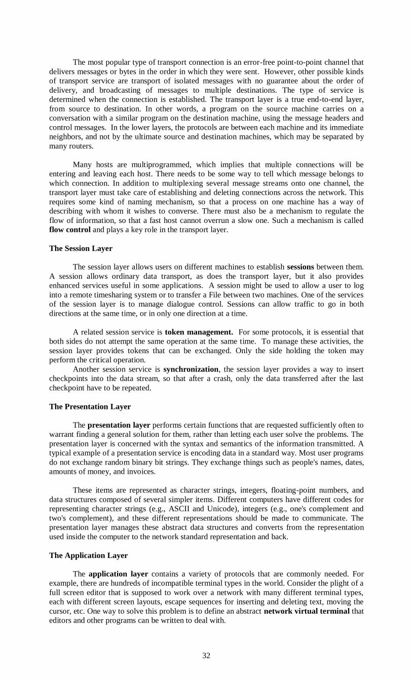
32
The most popular type of transport connection is an error-free point-to-point channel that
delivers messages or bytes in the order in which they were sent. However, other possible kinds
of transport service are transport of isolated messages with no guarantee about the order of
delivery, and broadcasting of messages to multiple destinations. The type of service is
determined when the connection is established. The transport layer is a true end-to-end layer,
from source to destination. In other words, a program on the source machine carries on a
conversation with a similar program on the destination machine, using the message headers and
control messages. In the lower layers, the protocols are between each machine and its immediate
neighbors, and not by the ultimate source and destination machines, which may be separated by
many routers.
Many hosts are multiprogrammed, which implies that multiple connections will be
entering and leaving each host. There needs to be some way to tell which message belongs to
which connection. In addition to multiplexing several message streams onto one channel, the
transport layer must take care of establishing and deleting connections across the network. This
requires some kind of naming mechanism, so that a process on one machine has a way of
describing with whom it wishes to converse. There must also be a mechanism to regulate the
flow of information, so that a fast host cannot overrun a slow one. Such a mechanism is called
flow control and plays a key role in the transport layer.
The Session Layer
The session layer allows users on different machines to establish sessions between them.
A session allows ordinary data transport, as does the transport layer, but it also provides
enhanced services useful in some applications. A session might be used to allow a user to log
into a remote timesharing system or to transfer a File between two machines. One of the services
of the session layer is to manage dialogue control. Sessions can allow traffic to go in both
directions at the same time, or in only one direction at a time.
A related session service is token management. For some protocols, it is essential that
both sides do not attempt the same operation at the same time. To manage these activities, the
session layer provides tokens that can be exchanged. Only the side holding the token may
perform the critical operation.
Another session service is synchronization, the session layer provides a way to insert
checkpoints into the data stream, so that after a crash, only the data transferred after the last
checkpoint have to be repeated.
The Presentation Layer
The presentation layer performs certain functions that are requested sufficiently often to
warrant finding a general solution for them, rather than letting each user solve the problems. The
presentation layer is concerned with the syntax and semantics of the information transmitted. A
typical example of a presentation service is encoding data in a standard way. Most user programs
do not exchange random binary bit strings. They exchange things such as people's names, dates,
amounts of money, and invoices.
These items are represented as character strings, integers, floating-point numbers, and
data structures composed of several simpler items. Different computers have different codes for
representing character strings (e.g., ASCII and Unicode), integers (e.g., one's complement and
two's complement), and these different representations should be made to communicate. The
presentation layer manages these abstract data structures and converts from the representation
used inside the computer to the network standard representation and back.
The Application Layer
The application layer contains a variety of protocols that are commonly needed. For
example, there are hundreds of incompatible terminal types in the world. Consider the plight of a
full screen editor that is supposed to work over a network with many different terminal types,
each with different screen layouts, escape sequences for inserting and deleting text, moving the
cursor, etc. One way to solve this problem is to define an abstract network virtual terminal that
editors and other programs can be written to deal with.

33
To handle each terminal type, a piece of software must be written to map the functions of
the network virtual terminal onto the real terminal. For example, when the editor moves the
virtual terminal's cursor to the upper left-hand corner of the screen, this software must issue the
proper command sequence to the real terminal to get its cursor there too. All the virtual terminal
software is in the application layer.
Another application layer function is file transfer. Different file systems have different
file naming conventions, different ways of representing text lines, and so on. Transferring a file
between two different systems requires handling these and other incompatibilities. This work,
too, belongs to the application layer, as do electronic mail, remote job entry, directory lookup,
and various other general purpose and special-purpose facilities.
The TCP/IP Reference model
ARPANET was a research network sponsored by the DOD (U.S Department of
Defense), connecting hundreds of universities and government installations, using leased
telephone lines.
When satellite and radio networks were added later, the existing protocols had trouble
interworking with them, so new reference architecture was needed. Thus, the ability to connect
multiple networks in a seamless way was one of the major design goals from the very beginning.
This architecture later became known as the TCP/IP Reference model. DOD wanted connections
to remain intact as long as the source and destination machines were functioning.
The Internet Layer
All these requirements led to the choice of a packet-switching network based on a
connectionless internetwork layer. This layer, called the internet layer, is the linchpin that holds
the whole architecture together. Its job is to permit hosts to inject packets into any network and
have them travel independently to the destination. They arrive in a different order than they were
sent, the job of higher layers to rearrange them.
The analogy here is with the (snail) mail system. A person can drop a sequence of
international letters into a mail box in one country and with a little luck, most of them will be
delivered to the correct address in the destination country, letters will travel through one or more
international mail gateways.
Each country (i.e., each network) has its own stamps, preferred envelope sizes and
delivery rules is hidden from the users. The internet layer defines an official packet format and
protocol called IP (INTERNET PROTOCOL). The job of the internet layer is to deliver IP
packets where they are supposed to go.
The Transport Layer
The layer above the internet layer in the TCP/IP model is the transport layer. It is
designed to allow peer entities on the source and destination hosts to carry on a conversation, just
as OSI transport layer. Two end-to-end transport protocols are defined, first one TCP
(Transmission Control Protocol), is a reliable connection-oriented protocol that allows a byte
stream originating on one machine to be delivered without error on any other machine in the
internet. It fragments the incoming byte stream into discrete messages and passes each one to the
internet layer. At the destination, the receiving TCP process reassembles the received messages
into the output stream. TCP also handles flow control to make fast sender cannot swamp slow
receiver with more messages than it can handle.
The second protocol is UDP (USER DATAGRAM PROTOCOL) is an un-reliable,
connectionless protocol for applications protocol for applications that do not want TCP’s
sequencing or flow control and wish to provide their own. It is also widely used for one-shot,
client-server-type request-reply queries and applications in which prompt delivery is more
important than accurate delivery.
The Application layer:
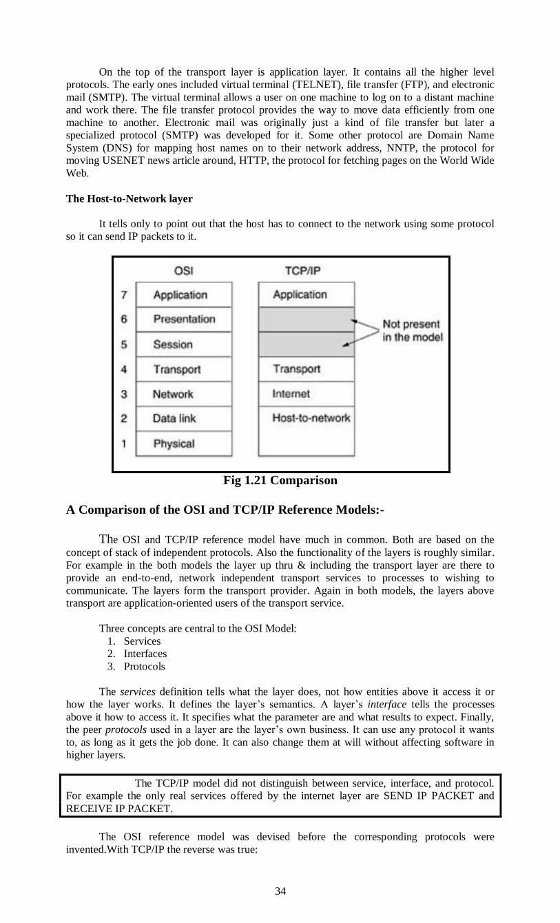
34
On the top of the transport layer is application layer. It contains all the higher level
protocols. The early ones included virtual terminal (TELNET), file transfer (FTP), and electronic
mail (SMTP). The virtual terminal allows a user on one machine to log on to a distant machine
and work there. The file transfer protocol provides the way to move data efficiently from one
machine to another. Electronic mail was originally just a kind of file transfer but later a
specialized protocol (SMTP) was developed for it. Some other protocol are Domain Name
System (DNS) for mapping host names on to their network address, NNTP, the protocol for
moving USENET news article around, HTTP, the protocol for fetching pages on the World Wide
Web.
The Host-to-Network layer
It tells only to point out that the host has to connect to the network using some protocol
so it can send IP packets to it.
Fig 1.21 Comparison
A Comparison of the OSI and TCP/IP Reference Models:-
The OSI and TCP/IP reference model have much in common. Both are based on the
concept of stack of independent protocols. Also the functionality of the layers is roughly similar.
For example in the both models the layer up thru & including the transport layer are there to
provide an end-to-end, network independent transport services to processes to wishing to
communicate. The layers form the transport provider. Again in both models, the layers above
transport are application-oriented users of the transport service.
Three concepts are central to the OSI Model:
1. Services
2. Interfaces
3. Protocols
The services definition tells what the layer does, not how entities above it access it or
how the layer works. It defines the layer’s semantics. A layer’s interface tells the processes
above it how to access it. It specifies what the parameter are and what results to expect. Finally,
the peer protocols used in a layer are the layer’s own business. It can use any protocol it wants
to, as long as it gets the job done. It can also change them at will without affecting software in
higher layers.
The TCP/IP model did not distinguish between service, interface, and protocol.
For example the only real services offered by the internet layer are SEND IP PACKET and
RECEIVE IP PACKET.
The OSI reference model was devised before the corresponding protocols were
invented.With TCP/IP the reverse was true:

35
The protocol came first, and the model was really just a description of the existing
protocols.
OSI model has seven layers and the TCP/IP has four layers. Both have (inter)network,
transport, and application layers, but the other layers are different.
OSI model supports both connection less and connection oriented communication in the
network layer, but only connection oriented communication in the transport layer.
The TCP/IP model has only one mode in the network layer but supports both modes in
the transport layer giving the user a choice. This choice is especially important for
simple request response protocols.
A Critique of the OSI Model and protocols:-
These lessons can be summarized as:
1. Bad timing.
2. Bad technology
3. Bad implementations
4. Bad politics
Bad timing
The time at which a standard is established is absolutely critical to its success. When the
subject is first discovered, there is a burst of research activity in the form of discussions, papers
and meetings. After a while this activity subsides, corporation discover the subject, and the
billion-dollar wave of investment hits. It is essential that the standard be return in the trough in
between the two elephants. If the standards are written too early, before the research is finished,
the subject may still be poorly understood; the result is bad standards. If they are written too late
so many companies may have already made major investments in different ways of doing things
that the standards are effectively ignored.
Bad technology
The choice of seven layers was more political than technical, and two of the layers
(session and presentation) are nearly empty, whereas two other ones (data link and network) are
overfull. The OSI model, along with the associated service definition and protocol, is
extraordinarily complex. Another problem with OSI that some functions, such as addressing,
flow control and error control, reappear again and again in each layer.
Bad Implementation
Complexity of the model and the protocols, it will come as no surprise the initial
implementation were huge, unwieldy and slow.
Bad Politics
OSI was widely thought to be the creature of the European telecommunication ministries,
the European community, and later the U.S. Government. Some people viewed this development
in the same light as IBM announcing in the 1960’s that PL/I was the language of the future or
DoD correcting this later by announcing it was actually Ada.
A Critique of the TCP/IP Reference Model The TCP/IP model and protocols have their problems too.
The model does not clearly distinguish the concepts of service, interface and protocol.
The model is not all general and is poorly suited to describing any protocol stack other
than TCP/IP.
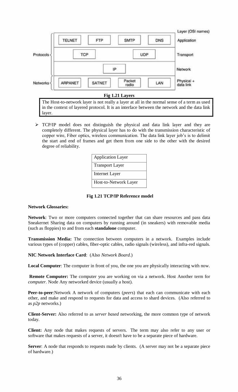
36
Fig 1.21 Layers
The Host-to-network layer is not really a layer at all in the normal sense of a term as used
in the context of layered protocol. It is an interface between the network and the data link
layer.
TCP/IP model does not distinguish the physical and data link layer and they are
completely different. The physical layer has to do with the transmission characteristic of
copper wire, Fiber optics, wireless communication. The data link layer job’s is to delimit
the start and end of frames and get them from one side to the other with the desired
degree of reliability.
Application Layer
Transport Layer
Internet Layer
Host-to-Network Layer
Fig 1.21 TCP/IP Reference model
Network Glossaries:
Network: Two or more computers connected together that can share resources and pass data
Sneakernet Sharing data on computers by running around (in sneakers) with removable media
(such as floppies) to and from each standalone computer.
Transmission Media: The connection between computers in a network. Examples include
various types of (copper) cables, fiber-optic cables, radio signals (wireless), and infra-red signals.
NIC Network Interface Card: (Also Network Board.)
Local Computer: The computer in front of you, the one you are physically interacting with now.
Remote Computer: The computer you are working on via a network. Host Another term for
computer. Node Any networked device (usually a host).
Peer-to-peer:Network A network of computers (peers) that each can communicate with each
other, and make and respond to requests for data and access to shard devices. (Also referred to
as p2p networks.)
Client-Server: Also referred to as server based networking, the more common type of network
today.
Client: Any node that makes requests of servers. The term may also refer to any user or
software that makes requests of a server, it doesn't have to be a separate piece of hardware.
Server: A node that responds to requests made by clients. (A server may not be a separate piece
of hardware.)
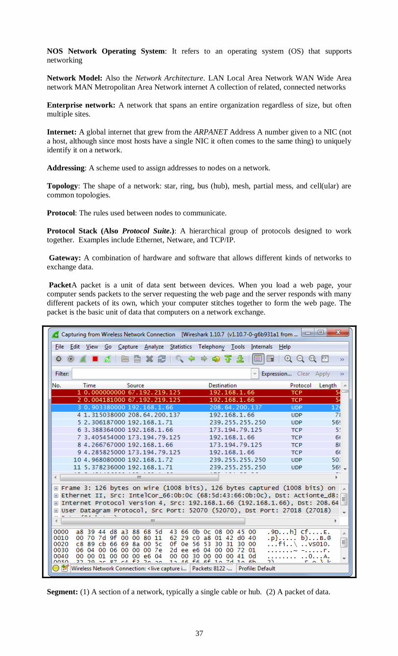
37
NOS Network Operating System: It refers to an operating system (OS) that supports
networking
Network Model: Also the Network Architecture. LAN Local Area Network WAN Wide Area
network MAN Metropolitan Area Network internet A collection of related, connected networks
Enterprise network: A network that spans an entire organization regardless of size, but often
multiple sites.
Internet: A global internet that grew from the ARPANET Address A number given to a NIC (not
a host, although since most hosts have a single NIC it often comes to the same thing) to uniquely
identify it on a network.
Addressing: A scheme used to assign addresses to nodes on a network.
Topology: The shape of a network: star, ring, bus (hub), mesh, partial mess, and cell(ular) are
common topologies.
Protocol: The rules used between nodes to communicate.
Protocol Stack (Also Protocol Suite.): A hierarchical group of protocols designed to work
together. Examples include Ethernet, Netware, and TCP/IP.
Gateway: A combination of hardware and software that allows different kinds of networks to
exchange data.
PacketA packet is a unit of data sent between devices. When you load a web page, your
computer sends packets to the server requesting the web page and the server responds with many
different packets of its own, which your computer stitches together to form the web page. The
packet is the basic unit of data that computers on a network exchange.
Segment: (1) A section of a network, typically a single cable or hub. (2) A packet of data.
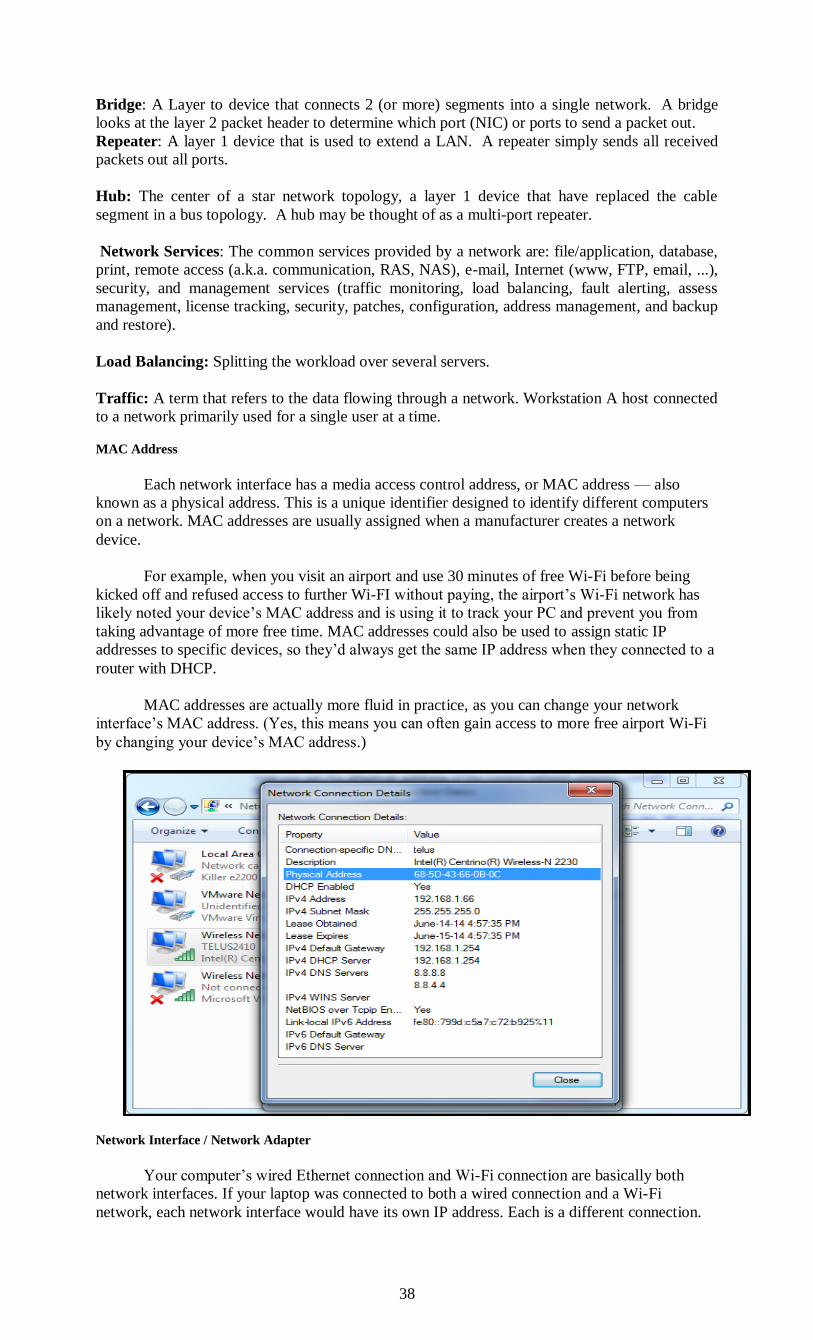
38
Bridge: A Layer to device that connects 2 (or more) segments into a single network. A bridge
looks at the layer 2 packet header to determine which port (NIC) or ports to send a packet out.
Repeater: A layer 1 device that is used to extend a LAN. A repeater simply sends all received
packets out all ports.
Hub: The center of a star network topology, a layer 1 device that have replaced the cable
segment in a bus topology. A hub may be thought of as a multi-port repeater.
Network Services: The common services provided by a network are: file/application, database,
print, remote access (a.k.a. communication, RAS, NAS), e-mail, Internet (www, FTP, email, ...),
security, and management services (traffic monitoring, load balancing, fault alerting, assess
management, license tracking, security, patches, configuration, address management, and backup
and restore).
Load Balancing: Splitting the workload over several servers.
Traffic: A term that refers to the data flowing through a network. Workstation A host connected
to a network primarily used for a single user at a time.
MAC Address
Each network interface has a media access control address, or MAC address — also
known as a physical address. This is a unique identifier designed to identify different computers
on a network. MAC addresses are usually assigned when a manufacturer creates a network
device.
For example, when you visit an airport and use 30 minutes of free Wi-Fi before being
kicked off and refused access to further Wi-FI without paying, the airport’s Wi-Fi network has
likely noted your device’s MAC address and is using it to track your PC and prevent you from
taking advantage of more free time. MAC addresses could also be used to assign static IP
addresses to specific devices, so they’d always get the same IP address when they connected to a
router with DHCP.
MAC addresses are actually more fluid in practice, as you can change your network
interface’s MAC address. (Yes, this means you can often gain access to more free airport Wi-Fi
by changing your device’s MAC address.)
Network Interface / Network Adapter
Your computer’s wired Ethernet connection and Wi-Fi connection are basically both
network interfaces. If your laptop was connected to both a wired connection and a Wi-Fi
network, each network interface would have its own IP address. Each is a different connection.

39
Network interfaces can also be implemented entirely in software, so they don’t always
directly correspond to hardware devices.
Localhost:
The hostname “localhost” always corresponds to the device you’re using. This uses the
loopback network interface — a network interface implemented in software — to connect
directly to your own PC.
localhost actually points to the IPv4 address 127.0.0.1 or the IPv6 address ::1 . Each
always corresponds to the current device.
IP Address
An Internet Protocol address, or IP address, is a numerical address that corresponds to
your computer on a network. When a computer wants to connect to another computer, it
connects to that computer’s IP address.
IPv4 and IPv6
There are two types of IP address in common use. Older IPv4 (IP version 4) addresses are
the most common, followed by newer IPv6 (IP version 6) addresses. IPv6 is necessary because
we just don’t have enough IPv4 addresses for all the people and devices in the world.
NAT
Network Address Translation, or NAT, is used by routers to share a single IP address
among many devices. For example, you probably have a wireless router at home that creates a
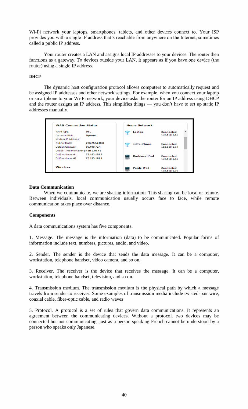
40
Wi-Fi network your laptops, smartphones, tablets, and other devices connect to. Your ISP
provides you with a single IP address that’s reachable from anywhere on the Internet, sometimes
called a public IP address.
Your router creates a LAN and assigns local IP addresses to your devices. The router then
functions as a gateway. To devices outside your LAN, it appears as if you have one device (the
router) using a single IP address.
DHCP
The dynamic host configuration protocol allows computers to automatically request and
be assigned IP addresses and other network settings. For example, when you connect your laptop
or smartphone to your Wi-Fi network, your device asks the router for an IP address using DHCP
and the router assigns an IP address. This simplifies things — you don’t have to set up static IP
addresses manually.
Data Communication
When we communicate, we are sharing information. This sharing can be local or remote.
Between individuals, local communication usually occurs face to face, while remote
communication takes place over distance.
Components
A data communications system has five components.
1. Message. The message is the information (data) to be communicated. Popular forms of
information include text, numbers, pictures, audio, and video.
2. Sender. The sender is the device that sends the data message. It can be a computer,
workstation, telephone handset, video camera, and so on.
3. Receiver. The receiver is the device that receives the message. It can be a computer,
workstation, telephone handset, television, and so on.
4. Transmission medium. The transmission medium is the physical path by which a message
travels from sender to receiver. Some examples of transmission media include twisted-pair wire,
coaxial cable, fiber-optic cable, and radio waves
5. Protocol. A protocol is a set of rules that govern data communications. It represents an
agreement between the communicating devices. Without a protocol, two devices may be
connected but not communicating, just as a person speaking French cannot be understood by a
person who speaks only Japanese.

41
Data Representation:
Information today comes in different forms such as text, numbers, images, audio, and
video.
Text:
In data communications, text is represented as a bit pattern, a sequence of bits (Os or Is).
Different sets of bit patterns have been designed to represent text symbols. Each set is called a
code, and the process of representing symbols is called coding. Today, the prevalent coding
system is called Unicode, which uses 32 bits to represent a symbol or character used in any
language in the world. The American Standard Code for Information Interchange (ASCII),
developed some decades ago in the United States, now constitutes the first 127 characters in
Unicode and is also referred to as Basic Latin.
Numbers:
Numbers are also represented by bit patterns. However, a code such as ASCII is not used
to represent numbers; the number is directly converted to a binary number to simplify
mathematical operations. Appendix B discusses several different numbering systems.
Images:
Images are also represented by bit patterns. In its simplest form, an image is composed
of a matrix of pixels (picture elements), where each pixel is a small dot. The size of the pixel
depends on the resolution. For example, an image can be divided into 1000 pixels or 10,000
pixels. In the second case, there is a better representation of the image (better resolution), but
more memory is needed to store the image. After an image is divided into pixels, each pixel is
assigned a bit pattern. The size and the value of the pattern depend on the image. For an image
made of only blackand- white dots (e.g., a chessboard), a I-bit pattern is enough to represent a
pixel.
If an image is not made of pure white and pure black pixels, you can increase the size of
the bit pattern to include gray scale. For example, to show four levels of gray scale, you can use
2-bit patterns.
A black pixel can be represented by 00, a dark gray pixel by 01, a light gray pixel by 10,
and a white pixel by 11. There are several methods to represent color images. One method is
called RGB, so called because each color is made of a combination of three primary colors: red,
green, and blue. The intensity of each color is measured, and a bit pattern is assigned to it.
Another method is called YCM, in which a color is made of a combination of three other primary
colors: yellow, cyan, and magenta.
Audio:
Audio refers to the recording or broadcasting of sound or music. Audio is by nature different
from text, numbers, or images. It is continuous, not discrete. Even when we use a microphone to

42
change voice or music to an electric signal, we create a continuous signal. In Chapters 4 and 5, we
learn how to change sound or music to a digital or an analog signal.
Video:
Video refers to the recording or broadcasting of a picture or movie. Video can either be
produced as a continuous entity (e.g., by a TV camera), or it can be a combination of images, each a
discrete entity, arranged to convey the idea of motion. Again we can change video to a digital or an
analog signal.
Data Flow
Communication between two devices can be simplex, half-duplex, or full-duplex as shown in
Figure
Simplex:
In simplex mode, the communication is unidirectional, as on a one-way street. Only one of
the two devices on a link can transmit; the other can only receive (see Figure a). Keyboards and
traditional monitors are examples of simplex devices. The keyboard can only introduce input; the
monitor can only accept output. The simplex mode can use the entire capacity of the channel to send
data in one direction.
Half-Duplex:
In half-duplex mode, each station can both transmit and receive, but not at the same time.
When one device is sending, the other can only receive, and vice versa The half-duplex mode is like
a one-lane road with traffic allowed in both directions.
When cars are traveling in one direction, cars going the other way must wait. In a half-duplex
transmission, the entire capacity of a channel is taken over by whichever of the two devices is
transmitting at the time. Walkie-talkies and CB (citizens band) radios are both half-duplex systems.
The half-The half-duplex mode is used in cases where there is no need for communication in both
directions at the same time; the entire capacity of the channel can be utilized for each direction.
Full-Duplex
In full-duplex both stations can transmit and receive simultaneously (see Figure c). The full-
duplex mode is like a tW<D-way street with traffic flowing in both directions at the same time. In
full-duplex mode, si~nals going in one direction share the capacity of the link: with signals going in
the other din~c~on. This sharing can occur in two ways:
Either the link must contain two physically separate t:nmsmissiIDn paths, one for sending
and the other for receiving; or the capacity of the ch:arillilel is divided between signals traveling in
both directions. One common example of full-duplex communication is the telephone network.
When two people are communicating by a telephone line, both can talk and listen at the same time.
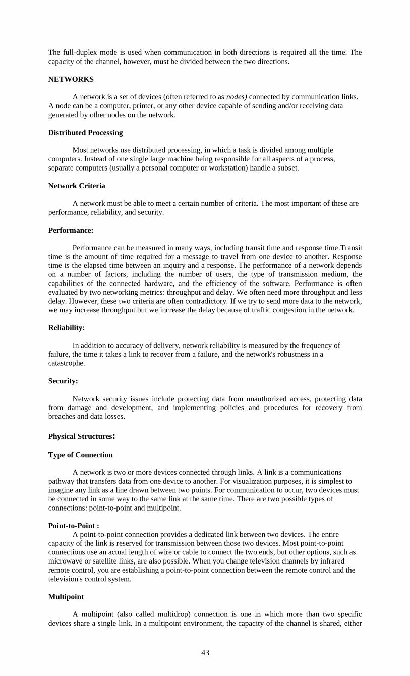
43
The full-duplex mode is used when communication in both directions is required all the time. The
capacity of the channel, however, must be divided between the two directions.
NETWORKS
A network is a set of devices (often referred to as nodes) connected by communication links.
A node can be a computer, printer, or any other device capable of sending and/or receiving data
generated by other nodes on the network.
Distributed Processing
Most networks use distributed processing, in which a task is divided among multiple
computers. Instead of one single large machine being responsible for all aspects of a process,
separate computers (usually a personal computer or workstation) handle a subset.
Network Criteria
A network must be able to meet a certain number of criteria. The most important of these are
performance, reliability, and security.
Performance:
Performance can be measured in many ways, including transit time and response time.Transit
time is the amount of time required for a message to travel from one device to another. Response
time is the elapsed time between an inquiry and a response. The performance of a network depends
on a number of factors, including the number of users, the type of transmission medium, the
capabilities of the connected hardware, and the efficiency of the software. Performance is often
evaluated by two networking metrics: throughput and delay. We often need more throughput and less
delay. However, these two criteria are often contradictory. If we try to send more data to the network,
we may increase throughput but we increase the delay because of traffic congestion in the network.
Reliability:
In addition to accuracy of delivery, network reliability is measured by the frequency of
failure, the time it takes a link to recover from a failure, and the network's robustness in a
catastrophe.
Security:
Network security issues include protecting data from unauthorized access, protecting data
from damage and development, and implementing policies and procedures for recovery from
breaches and data losses.
Physical Structures:
Type of Connection
A network is two or more devices connected through links. A link is a communications
pathway that transfers data from one device to another. For visualization purposes, it is simplest to
imagine any link as a line drawn between two points. For communication to occur, two devices must
be connected in some way to the same link at the same time. There are two possible types of
connections: point-to-point and multipoint.
Point-to-Point :
A point-to-point connection provides a dedicated link between two devices. The entire
capacity of the link is reserved for transmission between those two devices. Most point-to-point
connections use an actual length of wire or cable to connect the two ends, but other options, such as
microwave or satellite links, are also possible. When you change television channels by infrared
remote control, you are establishing a point-to-point connection between the remote control and the
television's control system.
Multipoint
A multipoint (also called multidrop) connection is one in which more than two specific
devices share a single link. In a multipoint environment, the capacity of the channel is shared, either
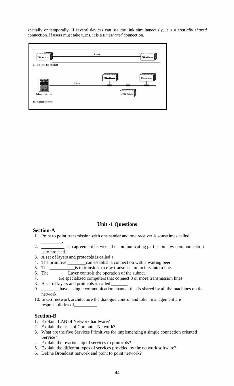
44
spatially or temporally. If several devices can use the link simultaneously, it is a spatially shared
connection. If users must take turns, it is a timeshared connection.
Unit -1 Questions
Section-A 1. Point to point transmission with one sender and one receiver is sometimes called
_________.
2. __________is an agreement between the communicating parties on how communication
is to proceed.
3. A set of layers and protocols is called a _________
4. The primitive ________can establish a connection with a waiting peer.
5. The ___________is to transform a raw transmission facility into a line.
6. The _______ Layer controls the operation of the subnet.
7. _______ are specialized computers that connect 3 or more transmission lines.
8. A set of layers and protocols is called _______
9. ________have a single communication channel that is shared by all the machines on the
network.
10. In OSI network architecture the dialogue control and token management are
responsibilities of__________
Section-B 1. Explain LAN of Network hardware?
2. Explain the uses of Computer Network?
3. What are the five Services Primitives for implementing a simple connection oriented
Service?
4. Explain the relationship of services to protocols?
5. Explain the different types of services provided by the network software?
6. Define Broadcast network and point to point network?
45
7. Define UniCasting and Multi casting
8. Write about the transmission technology?
9. What is datagram service?
10. Explain the three main categories of the wireless networks?
Section-C
1. Explain the topologies of the network?
2. Explain about the TCP/IP Reference model?
3. Differentiate between OSI and TCP/IP Reference Models?
4. Briefly Explain Network Hardware?
5. Explain about the uses of computer network?
6. What is the Critique of the OSI model and TCP/IP Reference Model?
7. Differentiate between broadcast network and Point to Point Network
8. Compare connection oriented and connection less service
9. Explain ISO/OSI reference model?
10. Briefly Explain Network Software?
UNIT-II:PHYSICAL LAYER - Guided Transmission Media: Magnetic Media – Twisted
Pair – Coaxial Cable – Fiber Optics. Wireless Transmission: Electromagnetic Spectrum–Radio
Transmission – Microwave Transmission – Infrared and Millimeter Waves – Light Waves.
Communication Satellites: Geostationary, Medium-Earth Orbit, Low Earth-orbitSatellites –
Satellites versus Fiber.
UNIT-II PHYSICAL LAYER Classes Of Transmission Media:
Conducted or guided media:use a conductor such as a wire or a fiber optic cable to move
the signal from sender to receiver.
Wireless or unguided media:use radio waves of different frequencies and do not need a
wire or cable conductor to transmit signals.
Design Factors for Transmission Media:
Bandwidth: All other factors remaining constant, the greater the band-width of a signal,
the higher the data rate that can be achieved.
Transmission impairments. Limit the distance a signal can travel.
Interference: Competing signals in overlapping frequency bands can distort or wipe out a
signal.
Number of receivers: Each attachment introduces some attenuation and distortion,
limiting distance and/or data rate.
Guided Transmission Media

46
The purpose of physical layer is to transport a raw bit stream from one machine to another.
Various physical media can be used for the actual transmission. Each one has its own niche in terms of
bandwidth, delay, cost, and ease of installation and maintenance. Media are grouped in to guided
media such as copper wire and fiber optics, and unguided media, such as radio and lasers through air.
Transmission capacity depends on the distance and on whether the medium is point-to-point or
multipoint.Examples:Twisted pair wires,Coaxial cables,optical Fiber
Magnetic Media:
One of the most common ways to transport data from one computer to another is to write them
onto magnetic tape or removable media (e.g., recordable DVDs) physically transport the tape or disks
to he destination machine, and read them back in again. Although this method is not as sophisticated
as using a geosynchronous communication satellite, it is more cost effective, and useful when high
bandwidth or cost per bit transported is the key factor. Though, the bandwidth characteristics of
magnetic tape are excellent, the delay characteristics are poor. Transmission time is measured in
minutes, hours or even days.
Twisted Pair:
Although the band width characteristics of magnetic tape are excellent, the delay
characteristics are poor. Many applications need an on-line connection. The most common medium for
transmission is twisted pair. A twisted pair consists of two insulated copper wires about 1mm thick.
The wires are twisted together in a helical form, the structure of a DNA molecule to avoid electrical
interference to similar pairs of wires close by. Twisting is done because two parallel wires constitute a
fine antenna. When the wires are twisted, the waves from different twists cancel out, so the wires
radiates less effectively.
The most common application of twisted pair is the telephone system. Nearly all telephones are
connected to the telephone company (telco) office by a twisted pair. Wires used can run for several
kilometers without amplification, but for longer distances repeaters are used. When many twisted pairs
run in parallel for a substantial distance, such as all the wires coming from an apartment building to
the telephone company office, there are bundled together and encased in a protective sheath. The pairs
in the bundles would interfere with each other if they are not twisted.
Twisted pairs can be used for either analog or digital transmission. The bandwidth depends on
the thickness of the wires and the distance traveled.
Due to their adequate performance and low cost, twisted pairs are widely used. Twisted pair
cabling comes in several varieties, two of which are important for computer networks. Category 3
twisted pairs consist of two insulated wires gently twisted together.
Four such pairs are grouped in a plastic sheath to protect the wires and keep them together,
category 3 cable running from a central wiring closet on each floor into each office. This scheme
allowed up to four regular telephones or two multiline telephones in each office to connect to the
telephone company equipment in the wiring closet.
The most advanced category 5 twisted pairs were introduced. They are similar to category 3
pairs, but with more twists per centimeter, which results in less crosstalk and a better-quality signal
over longer distances, making them more suitable for high-speed computer communication. Up-and-
coming categories are 6 and 7, which are capable of handling signals with bandwidths of 250 MHz
and 600 MHz, respectively. All of these wiring types are often referred as UTP (Unshielded Twisted
Pair), to contrast them with the bulky, expensive, shielded twisted pair cables IBM introduced in the
early 1980s.
Fig 2.1 Twisted PairsUnshielded twisted pair (UTP)
UTP cables are found in many Ethernet networks and telephone systems. For indoor telephone
applications, UTP is often grouped into sets of 25 pairs according to a standard 25-pair color code originally developed by AT&T Corporation. A typical subset of these colors (white/blue, blue/white, white/orange,
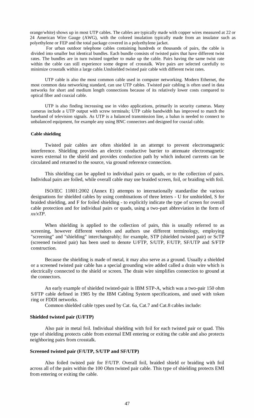
47
orange/white) shows up in most UTP cables. The cables are typically made with copper wires measured at 22 or 24 American Wire Gauge (AWG), with the colored insulation typically made from an insulator such as
polyethylene or FEP and the total package covered in a polyethylene jacket.
For urban outdoor telephone cables containing hundreds or thousands of pairs, the cable is
divided into smaller but identical bundles. Each bundle consists of twisted pairs that have different twist rates. The bundles are in turn twisted together to make up the cable. Pairs having the same twist rate
within the cable can still experience some degree of crosstalk. Wire pairs are selected carefully to
minimize crosstalk within a large cable.Unshielded twisted pair cable with different twist rates.
UTP cable is also the most common cable used in computer networking. Modern Ethernet, the
most common data networking standard, can use UTP cables. Twisted pair cabling is often used in data networks for short and medium length connections because of its relatively lower costs compared to
optical fiber and coaxial cable.
UTP is also finding increasing use in video applications, primarily in security cameras. Many cameras include a UTP output with screw terminals; UTP cable bandwidth has improved to match the
baseband of television signals. As UTP is a balanced transmission line, a balun is needed to connect to
unbalanced equipment, for example any using BNC connectors and designed for coaxial cable.
Cable shielding
Twisted pair cables are often shielded in an attempt to prevent electromagnetic
interference. Shielding provides an electric conductive barrier to attenuate electromagnetic
waves external to the shield and provides conduction path by which induced currents can be
circulated and returned to the source, via ground reference connection.
This shielding can be applied to individual pairs or quads, or to the collection of pairs.
Individual pairs are foiled, while overall cable may use braided screen, foil, or braiding with foil.
ISO/IEC 11801:2002 (Annex E) attempts to internationally standardise the various
designations for shielded cables by using combinations of three letters - U for unshielded, S for
braided shielding, and F for foiled shielding - to explicitly indicate the type of screen for overall
cable protection and for individual pairs or quads, using a two-part abbreviation in the form of
xx/xTP.
When shielding is applied to the collection of pairs, this is usually referred to as
screening, however different vendors and authors use different terminology, employing
"screening" and "shielding" interchangeably; for example, STP (shielded twisted pair) or ScTP
(screened twisted pair) has been used to denote U/FTP, S/UTP, F/UTP, SF/UTP and S/FTP
construction.
Because the shielding is made of metal, it may also serve as a ground. Usually a shielded
or a screened twisted pair cable has a special grounding wire added called a drain wire which is
electrically connected to the shield or screen. The drain wire simplifies connection to ground at
the connectors.
An early example of shielded twisted-pair is IBM STP-A, which was a two-pair 150 ohm
S/FTP cable defined in 1985 by the IBM Cabling System specifications, and used with token
ring or FDDI networks.
Common shielded cable types used by Cat. 6a, Cat.7 and Cat.8 cables include:
Shielded twisted pair (U/FTP)
Also pair in metal foil. Individual shielding with foil for each twisted pair or quad. This
type of shielding protects cable from external EMI entering or exiting the cable and also protects
neighboring pairs from crosstalk.
Screened twisted pair (F/UTP, S/UTP and SF/UTP)
Also foiled twisted pair for F/UTP. Overall foil, braided shield or braiding with foil
across all of the pairs within the 100 Ohm twisted pair cable. This type of shielding protects EMI
from entering or exiting the cable.

48
Screened shielded twisted pair (F/FTP and S/FTP)
Also fully shielded twisted pair, shielded screened twisted pair, screened foiled twisted
pair, shielded foiled twisted pair. Individual shielding using foil between the twisted pair sets,
and also an outer metal and/or foil shielding within the 100 Ohm twisted pair cable.[6] This type
of shielding protects EMI from entering or exiting the cable and also protects neighboring pairs
from crosstalk.
A series of new standards are in the works to include power over some of the unused wire
pairs in Twisted Pairs:
CAT 1-6. This would eliminate the need for separate power cables to some network
devices, and will likely be very popular. CAT 1 Unshielded, un-twisted cable with 2 pairs, usually used for voice but can support
up to 128 Kbps
CAT 2 UTP or STP with 4 pairs; can support up to 4 Mbps
CAT 3 UTP or STP with 4 pairs; can support up to 10 Mbps and was common in older
installations that only supported 4 Mbps token ring or 10 Mbps Ethernet. Has 3 to 4
twists per foot.
CAT 4 UTP with 4 pairs; can support up to 20 Mbps and was common to support
16 Mbps token ring. Has about 10 twists per foot. CAT 5UTP or STP with 4 pairs; can
support 100 Mbps. Has 36 to 48 twists per foot. (Very common today.)
CAT 5eUTP or STP with 4 pairs; can support 250 MHz. Has 48+ twists per foot. When
adding connectors, you must not untwist more than 1/2 inch of cable at each end, and
strip no more than 1 inch of insulation. (Note that even one inch of untwisted wires can
reduce throughput to less than 30 Mbps!) This is the current standard in new
construction and will support Gigabit Ethernet.
CAT 6 STP with 4 pairs; can support 100 Mbps. This is rarely used.
CAT 7 STP with 4 pairs; will support 750 MHz. This category of cable is not currently
standardized (3/2003). This cable will use different connectors than CAT 3-6 (i.e., not
RJ-45 connectors).
Fig 2.1 Twisted Pairs Connection
Networking media can be defined simply as the means by which signals (data) are sent
from one computer to another (either by cable or wireless means).
Advantages
It is a thin, flexible cable that is easy to string between walls
More lines can be run through the same wiring ducts
Electrical noise going into or coming from the cable can be prevented.
Cross-talk is minimized.
Disadvantages
Twisted pair's susceptibility to electromagnetic interference greatly depends on the pair
twisting schemes (usually patented by the manufacturers) staying intact during the installation.
As a result, twisted pair cables usually have stringent requirements for maximum pulling tension
as well as minimum bend radius. This relative fragility of twisted pair cables makes the
installation practices an important part of ensuring the cable's performance.
In video applications that send information across multiple parallel signal wires, twisted
pair cabling can introduce signaling delays known as skew which cause subtle color defects and
ghosting due to the image components not aligning correctly when recombined in the display
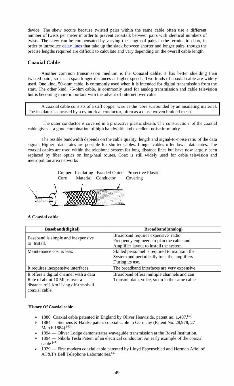
49
device. The skew occurs because twisted pairs within the same cable often use a different
number of twists per meter in order to prevent crosstalk between pairs with identical numbers of
twists. The skew can be compensated by varying the length of pairs in the termination box, in
order to introduce delay lines that take up the slack between shorter and longer pairs, though the
precise lengths required are difficult to calculate and vary depending on the overall cable length.
Coaxial Cable
Another common transmission medium is the Coaxial cable; it has better shielding than
twisted pairs, so it can span longer distances at higher speeds. Two kinds of coaxial cable are widely
used. One kind, 50-ohm cable, is commonly used when it is intended for digital transmission from the
start. The other kind, 75-ohm cable, is commonly used for analog transmission and cable television
but is becoming more important with the advent of Internet over cable.
A coaxial cable consists of a stiff copper wire as the core surrounded by an insulating material.
The insulator is encased by a cylindrical conductor, often as a close woven braided mesh.
The outer conductor is covered in a protective plastic sheath. The construction of the coaxial
cable gives it a good combination of high bandwidth and excellent noise immunity.
The ossible bandwidth depends on the cable quality, length and signal-to-noise ratio of the data
signal. Higher data rates are possible for shorter cables. Longer cables offer lower data rates. The
coaxial cables are used within the telephone system for long-distance lines but have now largely been
replaced by fiber optics on long-haul routes. Coax is still widely used for cable television and
metropolitan area networks
A Coaxial cable
History Of Coaxial cable
1880 Coaxial cable patented in England by Oliver Heaviside, patent no. 1,407.[39]
1884 — Siemens & Halske patent coaxial cable in Germany (Patent No. 28,978, 27
March 1884).[40]
1894 — Oliver Lodge demonstrates waveguide transmission at the Royal Institution.
1894 — Nikola Tesla Patent of an electrical conductor. An early example of the coaxial
cable [41]
1929 — First modern coaxial cable patented by Lloyd Espenschied and Herman Affel of
AT&T's Bell Telephone Laboratories.[42]
Baseband(digital) Broadband(analog)
Baseband is simple and inexpensive
to Install.
Broadband requires expensive radio
Frequency engineers to plan the cable and
Amplifier layout to install the system.
Maintenance cost is less. Skilled personnel is required to maintain the
System and periodically tune the amplifiers
During its use.
It requires inexpensive interfaces. The broadband interfaces are very expensive.
It offers a digital channel with a data
Rate of about 10 Mbps over a
distance of 1 km Using off-the-shelf
coaxial cable.
Broadband offers multiple channels and can
Transmit data, voice, so on in the same cable
Copper Insulating Braided Outer Protective Plastic
Core Material Conductor Covering
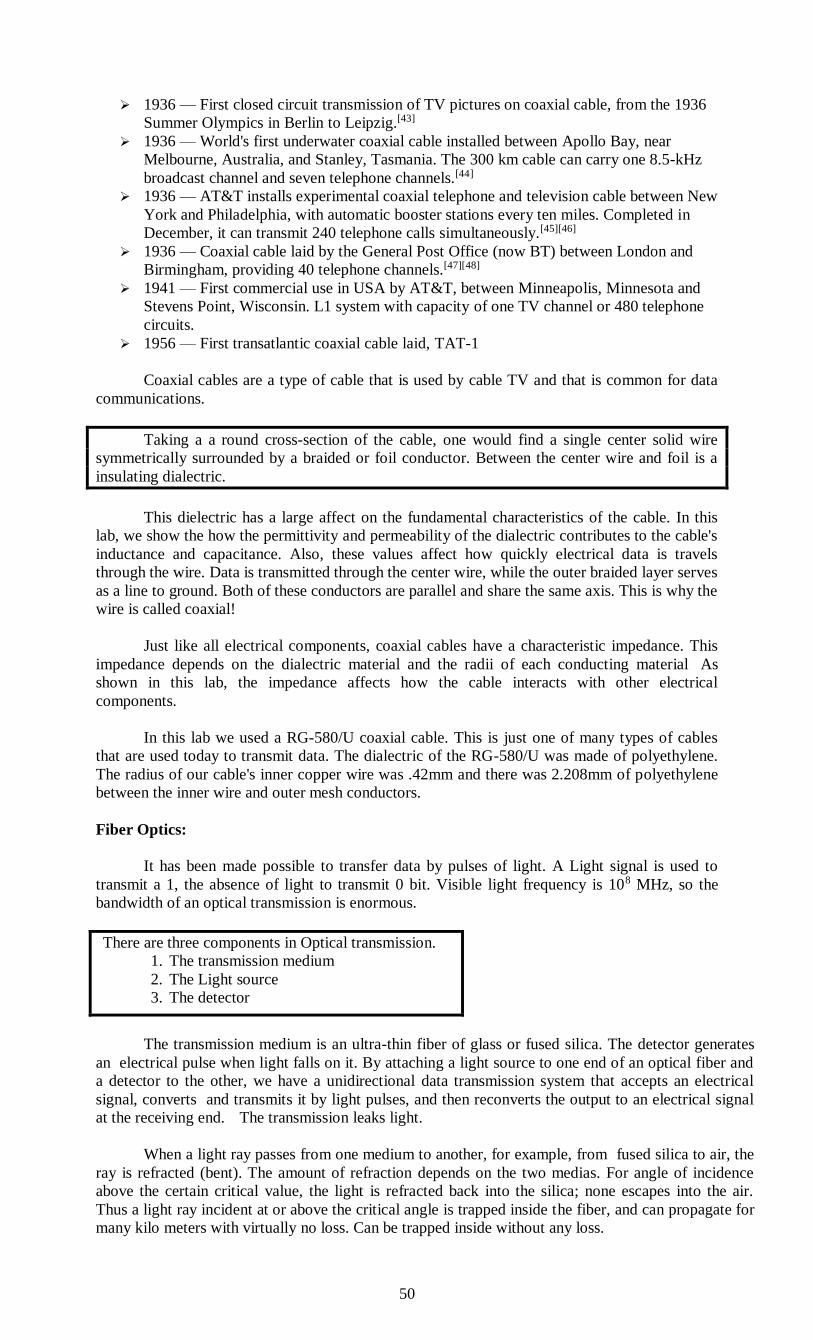
50
1936 — First closed circuit transmission of TV pictures on coaxial cable, from the 1936
Summer Olympics in Berlin to Leipzig.[43]
1936 — World's first underwater coaxial cable installed between Apollo Bay, near
Melbourne, Australia, and Stanley, Tasmania. The 300 km cable can carry one 8.5-kHz
broadcast channel and seven telephone channels.[44]
1936 — AT&T installs experimental coaxial telephone and television cable between New
York and Philadelphia, with automatic booster stations every ten miles. Completed in
December, it can transmit 240 telephone calls simultaneously.[45][46]
1936 — Coaxial cable laid by the General Post Office (now BT) between London and
Birmingham, providing 40 telephone channels.[47][48]
1941 — First commercial use in USA by AT&T, between Minneapolis, Minnesota and
Stevens Point, Wisconsin. L1 system with capacity of one TV channel or 480 telephone
circuits.
1956 — First transatlantic coaxial cable laid, TAT-1
Coaxial cables are a type of cable that is used by cable TV and that is common for data
communications.
Taking a a round cross-section of the cable, one would find a single center solid wire
symmetrically surrounded by a braided or foil conductor. Between the center wire and foil is a
insulating dialectric.
This dielectric has a large affect on the fundamental characteristics of the cable. In this
lab, we show the how the permittivity and permeability of the dialectric contributes to the cable's
inductance and capacitance. Also, these values affect how quickly electrical data is travels
through the wire. Data is transmitted through the center wire, while the outer braided layer serves
as a line to ground. Both of these conductors are parallel and share the same axis. This is why the
wire is called coaxial!
Just like all electrical components, coaxial cables have a characteristic impedance. This
impedance depends on the dialectric material and the radii of each conducting material As
shown in this lab, the impedance affects how the cable interacts with other electrical
components.
In this lab we used a RG-580/U coaxial cable. This is just one of many types of cables
that are used today to transmit data. The dialectric of the RG-580/U was made of polyethylene.
The radius of our cable's inner copper wire was .42mm and there was 2.208mm of polyethylene
between the inner wire and outer mesh conductors.
Fiber Optics:
It has been made possible to transfer data by pulses of light. A Light signal is used to
transmit a 1, the absence of light to transmit 0 bit. Visible light frequency is 108 MHz, so the
bandwidth of an optical transmission is enormous.
There are three components in Optical transmission.
1. The transmission medium
2. The Light source
3. The detector
The transmission medium is an ultra-thin fiber of glass or fused silica. The detector generates
an electrical pulse when light falls on it. By attaching a light source to one end of an optical fiber and
a detector to the other, we have a unidirectional data transmission system that accepts an electrical
signal, converts and transmits it by light pulses, and then reconverts the output to an electrical signal
at the receiving end. The transmission leaks light.
When a light ray passes from one medium to another, for example, from fused silica to air, the
ray is refracted (bent). The amount of refraction depends on the two medias. For angle of incidence
above the certain critical value, the light is refracted back into the silica; none escapes into the air.
Thus a light ray incident at or above the critical angle is trapped inside the fiber, and can propagate for
many kilo meters with virtually no loss. Can be trapped inside without any loss.
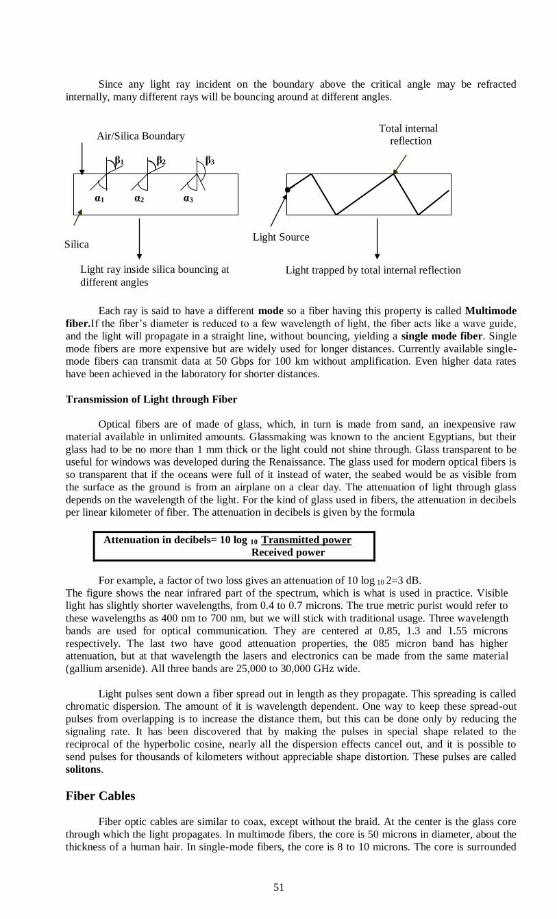
51
Since any light ray incident on the boundary above the critical angle may be refracted
internally, many different rays will be bouncing around at different angles.
β1 β2 β3
Each ray is said to have a different mode so a fiber having this property is called Multimode
fiber.If the fiber’s diameter is reduced to a few wavelength of light, the fiber acts like a wave guide,
and the light will propagate in a straight line, without bouncing, yielding a single mode fiber. Single
mode fibers are more expensive but are widely used for longer distances. Currently available single-
mode fibers can transmit data at 50 Gbps for 100 km without amplification. Even higher data rates
have been achieved in the laboratory for shorter distances.
Transmission of Light through Fiber
Optical fibers are of made of glass, which, in turn is made from sand, an inexpensive raw
material available in unlimited amounts. Glassmaking was known to the ancient Egyptians, but their
glass had to be no more than 1 mm thick or the light could not shine through. Glass transparent to be
useful for windows was developed during the Renaissance. The glass used for modern optical fibers is
so transparent that if the oceans were full of it instead of water, the seabed would be as visible from
the surface as the ground is from an airplane on a clear day. The attenuation of light through glass
depends on the wavelength of the light. For the kind of glass used in fibers, the attenuation in decibels
per linear kilometer of fiber. The attenuation in decibels is given by the formula
Attenuation in decibels= 10 log 10 Transmitted power
Received power
For example, a factor of two loss gives an attenuation of 10 log 10 2=3 dB.
The figure shows the near infrared part of the spectrum, which is what is used in practice. Visible
light has slightly shorter wavelengths, from 0.4 to 0.7 microns. The true metric purist would refer to
these wavelengths as 400 nm to 700 nm, but we will stick with traditional usage. Three wavelength
bands are used for optical communication. They are centered at 0.85, 1.3 and 1.55 microns
respectively. The last two have good attenuation properties, the 085 micron band has higher
attenuation, but at that wavelength the lasers and electronics can be made from the same material
(gallium arsenide). All three bands are 25,000 to 30,000 GHz wide.
Light pulses sent down a fiber spread out in length as they propagate. This spreading is called
chromatic dispersion. The amount of it is wavelength dependent. One way to keep these spread-out
pulses from overlapping is to increase the distance them, but this can be done only by reducing the
signaling rate. It has been discovered that by making the pulses in special shape related to the
reciprocal of the hyperbolic cosine, nearly all the dispersion effects cancel out, and it is possible to
send pulses for thousands of kilometers without appreciable shape distortion. These pulses are called
solitons.
Fiber Cables
Fiber optic cables are similar to coax, except without the braid. At the center is the glass core
through which the light propagates. In multimode fibers, the core is 50 microns in diameter, about the
thickness of a human hair. In single-mode fibers, the core is 8 to 10 microns. The core is surrounded
Air/Silica Boundary
α1 α2 α3
Light Source
Light ray inside silica bouncing at
different angles Light trapped by total internal reflection
Total internal
reflection
Silica

52
by a glass cladding with a lower index of refraction than the core, to keep all the light in the core. Next
comes a thin plastic jacket to protect the cladding. Fibers are grouped in bundles, protected by an outer
sheath.
An optical fiber (or optical fibre) is a flexible, transparent fiber made of extruded glass
(silica) or plastic, slightly thicker than a human hair. It can function as a waveguide, or “light pipe”, to
transmit light between the two ends of the fiber.The field of applied science and engineering
concerned with the design and application of optical fibers is known as fiber optics.
Terrestrial fiber sheaths are normally laid in the ground within a meter of the surface, where
they are occasionally subject to attacks by backhoes or gophers. Near the shore, transoceanic fiber
sheaths are buried in trenches by a kind of seaplow. In deep water, they just lie on the bottom, where
they can be snagged by fishing trawlers or attacked by giant squid.
Fibers can be connected in three different ways.
1. First, they can terminate in connectors and be plugged into fiber sockets. Connectors lose about
10 to 20 percent of the light, but they make is easy to reconfigure systems.
2. Second, they can be spliced mechanically. Mechanical splices just lay the two carefully-cut
ends next to each other in s special sleeve and clamp them in place. Alignment can be
improved by passing light through the junction and then making small adjustments to
maximize the signal. Mechanical splices take trained personnel about 5 minutes and result in a
10 percent light loss.
3. Third, two pieces of fiber can be fused (melted) to form a solid connection. A fusion splice is
as good as a single drawn fiber, but a small amount of attenuation occurs. For all three kinds of
splices, reflections can occur at the point of the splice, and the reflected energy can interfere
with the signal.
Two kinds of light sources are used to do the signaling, LEDs (Light Emitting Diodes) and
semiconductor lasers. They have different properties shown below.
Item LED Semiconductor laser
Data rate Low High
Fiber type Multimode Multimode or single mode
Distance Short Long
Lifetime Long life Short life
Temperature sensitivity Minor Substantial
Cost Low cost Expensive
They can be tuned in wavelength by inserting Fabry-perot or Mach-Zehnder interferometers
between the source and the fiber. Fabry-perot interferometers are simple resonant cavities consisting
of two parallel mirrors. The light is incident perpendicular to the mirrors. The length of the cavity
selects out those wavelengths that fit inside an integral number of times. Mach- Zehnder
interferometers separate the light in to two beams. The two beams travel slightly different distances.
They are recombined at the end and are in phase for only certain wavelengths. The receiving
end of an optical fiber consists of a photodiode, which gives off an electrical pulse when struck by
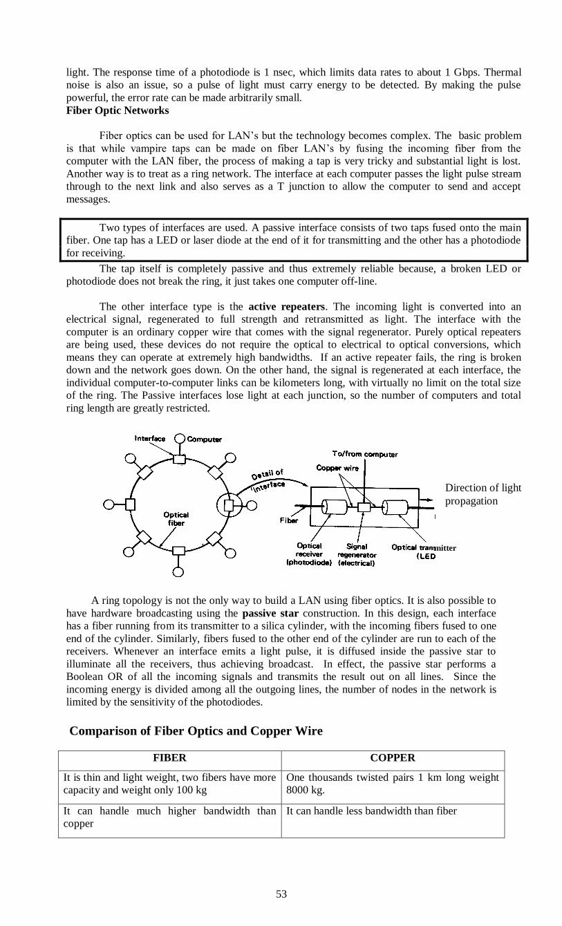
53
mitter
light. The response time of a photodiode is 1 nsec, which limits data rates to about 1 Gbps. Thermal
noise is also an issue, so a pulse of light must carry energy to be detected. By making the pulse
powerful, the error rate can be made arbitrarily small.
Fiber Optic Networks
Fiber optics can be used for LAN’s but the technology becomes complex. The basic problem
is that while vampire taps can be made on fiber LAN’s by fusing the incoming fiber from the
computer with the LAN fiber, the process of making a tap is very tricky and substantial light is lost.
Another way is to treat as a ring network. The interface at each computer passes the light pulse stream
through to the next link and also serves as a T junction to allow the computer to send and accept
messages.
Two types of interfaces are used. A passive interface consists of two taps fused onto the main
fiber. One tap has a LED or laser diode at the end of it for transmitting and the other has a photodiode
for receiving.
The tap itself is completely passive and thus extremely reliable because, a broken LED or
photodiode does not break the ring, it just takes one computer off-line.
The other interface type is the active repeaters. The incoming light is converted into an
electrical signal, regenerated to full strength and retransmitted as light. The interface with the
computer is an ordinary copper wire that comes with the signal regenerator. Purely optical repeaters
are being used, these devices do not require the optical to electrical to optical conversions, which
means they can operate at extremely high bandwidths. If an active repeater fails, the ring is broken
down and the network goes down. On the other hand, the signal is regenerated at each interface, the
individual computer-to-computer links can be kilometers long, with virtually no limit on the total size
of the ring. The Passive interfaces lose light at each junction, so the number of computers and total
ring length are greatly restricted.
A ring topology is not the only way to build a LAN using fiber optics. It is also possible to
have hardware broadcasting using the passive star construction. In this design, each interface
has a fiber running from its transmitter to a silica cylinder, with the incoming fibers fused to one
end of the cylinder. Similarly, fibers fused to the other end of the cylinder are run to each of the
receivers. Whenever an interface emits a light pulse, it is diffused inside the passive star to
illuminate all the receivers, thus achieving broadcast. In effect, the passive star performs a
Boolean OR of all the incoming signals and transmits the result out on all lines. Since the
incoming energy is divided among all the outgoing lines, the number of nodes in the network is
limited by the sensitivity of the photodiodes.
Comparison of Fiber Optics and Copper Wire
FIBER COPPER
It is thin and light weight, two fibers have more
capacity and weight only 100 kg
One thousands twisted pairs 1 km long weight
8000 kg.
It can handle much higher bandwidth than
copper
It can handle less bandwidth than fiber
Direction of light
propagation

54
Due to the low attenuation, repeaters are needed
only about every 50 km on long lines.
Due to the low attenuation, repeaters are needed
only about every 5 km for copper a substantial
cost saving.
It is affected by corrosive chemicals in the air. Copper is affected by power surges,
electromagnetic interference or power failures.
It greatly reduces the need for expensive
mechanical support systems, fiber wins hands
down due to its lower installation cost. Fiber
interfaces cost more than electrical interfaces.
It is inexpensive.
Fibers do not leak light and are quite difficult to
tap. Fibers can be damaged easily by being bent
too much.
The copper has excellent resale value to copper
refiners who see it as very high grade ore.
Fiber excellent security against wiretappers,
since optical transmission is inherently
unidirectional, two-way communication
requires either two fiber or two frequency bands
on one fiber
Copper wire is used for two-way
communications.
Optical Fibre
Three components: light source, transmission system, and a detector
The detector generates an electric pulse when hit by light
1-a pulse of light; 0-missing pulse of light.
optical rays travel in glass or plastic core
When light move from one medium to another it bend at the boundary. The amount of
bending depends on the properties of the media.
Light at shallow angles propagate along the fibre, and those that are less than critical
angle are absorbed in the jacket
The cladding is a glass or plastic with properties that differ from those of the core.
Used in long distance communication, in locations having small amount of space, and
with reduction in price is starting to get also to LANs.
Not affected by external electromagnetic fields, and do not radiate energy. Hence,
providing high degree of security from eavesdropping.
Provide for multimode of propagation at different angles of reflections. Cause signal
elements to spread out in time, which limits the rate in which data can be accurately
received
55
Reduction of the radius of the core implies less reflected angles. Single mode is achieved
with sufficient small radius.
A multimode graded index transmission is obtained by varying the index of reflection
of the core to improve on the multi mode option without resolving to the cost of single
mode. (index of reflection=speed in vacuum / speed in medium.)
1 Gbps is the current limitation, with the bottle neck in the conversion from electrical to
optical signals. Large improvements are expected.
Optical fibers are widely used in fiber-optic communications, where they permit
transmission over longer distances and at higher bandwidths (data rates) than wire cables. Fibers
are used instead of metal wires because signals travel along them with less loss and are also
immune to electromagnetic interference. Fibers are also used for illumination, and are wrapped
in bundles so that they may be used to carry images, thus allowing viewing in confined spaces.
Specially designed fibers are used for a variety of other applications, including sensors and fiber
lasers.
Optical fibers typically include a transparent core surrounded by a transparent cladding
material with a lower index of refraction. Light is kept in the core by total internal reflection.
This causes the fiber to act as a waveguide. Fibers that support many propagation paths or
transverse modes are called multi-mode fibers (MMF), while those that only support a single
mode are called single-mode fibers (SMF). Multi-mode fibers generally have a wider core
diameter, and are used for short-distance communication links and for applications where high
power must be transmitted. Single-mode fibers are used for most communication links longer
than 1,000 meters (3,300 ft).
Joining lengths of optical fiber is more complex than joining electrical wire or cable. The
ends of the fibers must be carefully cleaved, and then carefully spliced together with the cores
perfectly aligned. A mechanical splice holds the ends of the fibers together mechanically, while
fusion splicing uses heat to fuse the ends of the fibers together. Special optical fiber connectors
for temporary or semi-permanent connections are also available.
Advantages over copper wiring
The advantages of optical fiber communication with respect to copper wire systems are:
Broad bandwidth
A single optical fiber can carry 3,000,000 full-duplex voice calls or 90,000 TV channels.
Immunity to electromagnetic interference
Light transmission through optical fibers is unaffected by other electromagnetic radiation
nearby.
The optical fiber is electrically non-conductive, so it does not act as an antenna to pick up
electromagnetic signals.
Information traveling inside the optical fiber is immune to electromagnetic interference,
even electromagnetic pulses generated by nuclear devices.
Low attenuation loss over long distances
Attenuation loss can be as low as 0.2 dB/km in optical fiber cables, allowing transmission
over long distances without the need for repeaters.
Electrical insulator
Optical fibers do not conduct electricity, preventing problems with ground loops and
conduction of lightning.
Optical fibers can be strung on poles alongside high voltage power cables.
Material cost and theft prevention
Conventional cable systems use large amounts of copper. In some places, this copper is a
target for theft due to its value on the scrap market.
Media Comparison:
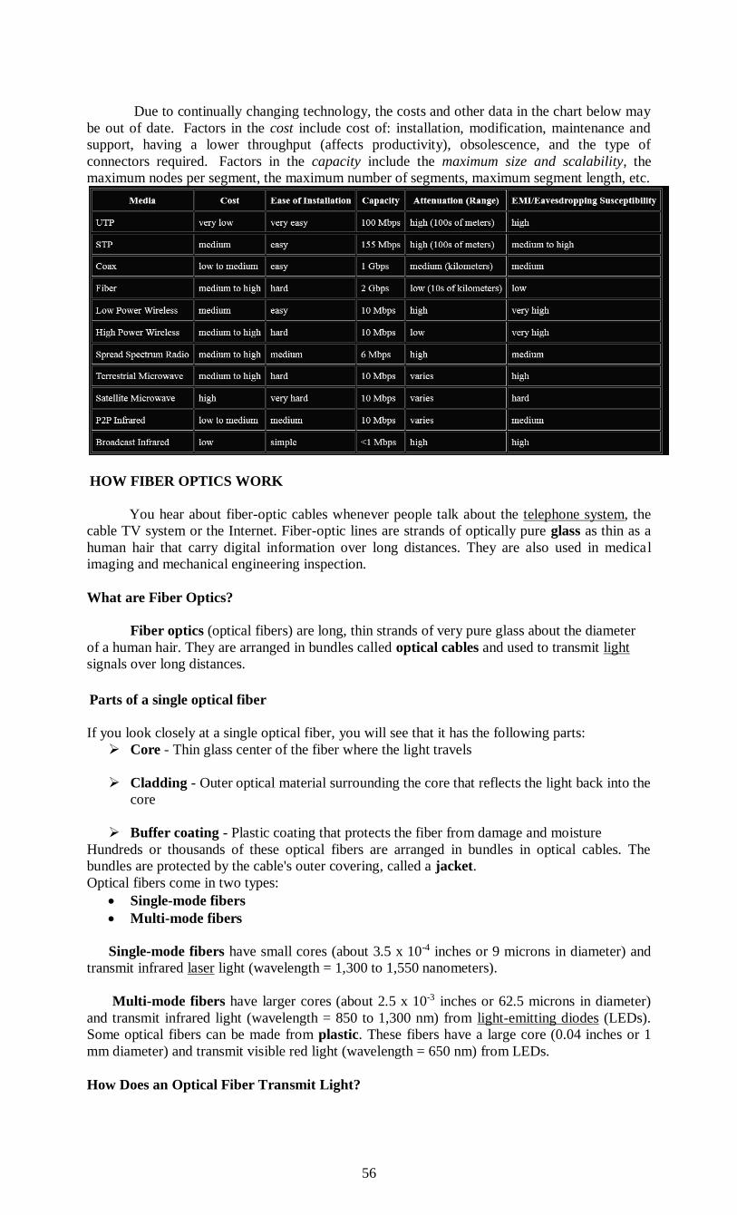
56
Due to continually changing technology, the costs and other data in the chart below may
be out of date. Factors in the cost include cost of: installation, modification, maintenance and
support, having a lower throughput (affects productivity), obsolescence, and the type of
connectors required. Factors in the capacity include the maximum size and scalability, the
maximum nodes per segment, the maximum number of segments, maximum segment length, etc.
HOW FIBER OPTICS WORK
You hear about fiber-optic cables whenever people talk about the telephone system, the
cable TV system or the Internet. Fiber-optic lines are strands of optically pure glass as thin as a
human hair that carry digital information over long distances. They are also used in medical
imaging and mechanical engineering inspection.
What are Fiber Optics?
Fiber optics (optical fibers) are long, thin strands of very pure glass about the diameter
of a human hair. They are arranged in bundles called optical cables and used to transmit light
signals over long distances.
Parts of a single optical fiber
If you look closely at a single optical fiber, you will see that it has the following parts:
Core - Thin glass center of the fiber where the light travels
Cladding - Outer optical material surrounding the core that reflects the light back into the
core
Buffer coating - Plastic coating that protects the fiber from damage and moisture
Hundreds or thousands of these optical fibers are arranged in bundles in optical cables. The
bundles are protected by the cable's outer covering, called a jacket.
Optical fibers come in two types:
Single-mode fibers
Multi-mode fibers
Single-mode fibers have small cores (about 3.5 x 10⁻⁴ inches or 9 microns in diameter) and
transmit infrared laser light (wavelength = 1,300 to 1,550 nanometers).
Multi-mode fibers have larger cores (about 2.5 x 10⁻³ inches or 62.5 microns in diameter)
and transmit infrared light (wavelength = 850 to 1,300 nm) from light-emitting diodes (LEDs).
Some optical fibers can be made from plastic. These fibers have a large core (0.04 inches or 1
mm diameter) and transmit visible red light (wavelength = 650 nm) from LEDs.
How Does an Optical Fiber Transmit Light?

57
Suppose you want to shine a flashlight beam down a long, straight hallway. Just point the
beam straight down the hallway -- light travels in straight lines, so it is no problem. What if the
hallway has a bend in it? You could place a mirror at the bend to reflect the light beam around
the corner. What if the hallway is very winding with multiple bends? You might line the walls
with mirrors and angle the beam so that it bounces from side-to-side all along the hallway. This
is exactly what happens in an optical fiber.
The light in a fiber-optic cable travels through the core (hallway) by constantly bouncing
from the cladding (mirror-lined walls), a principle called total internal reflection.
Because the cladding does not absorb any light from the core, the light wave can travel
great distances. However, some of the light signal degrades within the fiber, mostly due to
impurities in the glass. The extent that the signal degrades depends on the purity of the glass and
the wavelength of the transmitted light (for example, 850 nm = 60 to 75 percent/km; 1,300 nm =
50 to 60 percent/km; 1,550 nm is greater than 50 percent/km). Some premium optical fibers
show much less signal degradation -- less than 10 percent/km at 1,550 nm.
A fiber-optic relay system
To understand how optical fibers are used in communications systems, let's look at an
example from a World War II movie or documentary where two naval ships in a fleet need to
communicate with each other while maintaining radio silence or on stormy seas. One ship pulls
up alongside the other. The captain of one ship sends a message to a sailor on deck. The sailor
translates the message into Morse code (dots and dashes) and uses a signal light (floodlight with
a venetian blind type shutter on it) to send the message to the other ship. A sailor on the deck of
the other ship sees the Morse code message, decodes it into English and sends the message up to
the captain.
Imagine doing this when the ships are on either side of the ocean separated by thousands of
miles and you have a fiber-optic communication system in place between the two ships. Fiber-
optic relay systems consist of the following:
Transmitter - Produces and encodes the light signals
Optical fiber - Conducts the light signals over a distance
Optical regenerator - May be necessary to boost the light signal (for long distances)
Optical receiver - Receives and decodes the light signals
Transmitter
The transmitter is like the sailor on the deck of the sending ship. It receives and directs
the optical device to turn the light "on" and "off" in the correct sequence, thereby generating a
light signal.
The transmitter is physically close to the optical fiber and may even have a lens to focus
the light into the fiber. Lasers have more power than LEDs, but vary more with changes in
temperature and are more expensive. The most common wavelengths of light signals are 850 nm,
1,300 nm, and 1,550 nm (infrared, non-visible portions of the spectrum).
Optical Regenerator
As mentioned above, some signal loss occurs when the light is transmitted through the
fiber, especially over long distances (more than a half mile, or about 1 km) such as with undersea
cables.
Therefore, one or more optical regenerators is spliced along the cable to boost the
degraded light signals.
An optical regenerator consists of optical fibers with a special coating (doping). The
doped portion is "pumped" with a laser. When the degraded signal comes into the doped coating,
the energy from the laser allows the doped molecules to become lasers themselves. The doped
molecules then emit a new, stronger light signal with the same characteristics as the incoming
weak light signal. Basically, the regenerator is a laser amplifier for the incoming signal.

58
Optical Receiver
The optical receiver is like the sailor on the deck of the receiving ship. It takes the
incoming digital light signals, decodes them and sends the electrical signal to the other user's
computer, TV or telephone (receiving ship's captain). The receiver uses a photocell or
photodiode to detect the light.
Advantages of Fiber Optics
Why are fiber-optic systems revolutionizing telecommunications? Compared to conventional
metal wire (copper wire), optical fibers are:
Less expensive
Thinner
Higher carrying capacity
Non-flammable
Lightweight
Flexible
Medical imaging
Mechanical imaging
Plumbing
How Are Optical Fibers Made?
Optical fibers are made of extremely pure optical glass. We think of a glass window as
transparent, but the thicker the glass gets, the less transparent it becomes due to impurities in the
glass. However, the glass in an optical fiber has far fewer impurities than window-pane glass.
One company's description of the quality of glass is as follows: If you were on top of an ocean
that is miles of solid core optical fiber glass, you could see the bottom clearly.
Testing the Finished Optical Fiber
The finished optical fiber is tested for the following:
Tensile strength - Must withstand 100,000 lb/in2 or more
Refractive index profile - Determine numerical aperture as well as screen for optical
defects
Fiber geometry - Core diameter, cladding dimensions and coating diameter are uniform
Attenuation - Determine the extent that light signals of various wavelengths degrade over
distance
Information carrying capacity (bandwidth) - Number of signals that can be carried at one
time (multi-mode fibers)
Chromatic dispersion - Spread of various wavelengths of light through the core
(important for bandwidth)
Operating temperature/humidity range
Temperature dependence of attenuation
Ability to conduct light underwater - Important for undersea cables
Once the fibers have passed the quality control, they are sold to telephone companies, cable
companies and network providers. Many companies are currently replacing their old copper-
wire-based systems with new fiber-optic-based systems to improve speed, capacity and clarity.
Wireless Transmission
Our age has given rise to information junkies: people who need to be online all the time.
For these mobile users, twisted pair, coax, and fiber optics are of no use. They need to get their
‘‘hits’’ of data for their laptop, notebook, shirt pocket,palmtop, or wristwatch computers without
being tethered to the terrestrial communication infrastructure. For these users, wireless
communication is the answer.
In the following sections, we will look at wireless communication in general.It has many
other important applications besides providing connectivity to users who want to surf the Web
from the beach.Wireless has advantages for even fixed devices in some circumstances. For
example, if running a fiber to a building is difficult due to the terrain (mountains, jungles,
59
swamps, etc.), wireless may be better. It is noteworthy that modern wireless digital
communication began in the Hawaiian Islands, where large chunks of Pacific Ocean
separated the users from their computer center and the telephone system was inadequate.
Wireless transmission is a form of unguided media. Wireless communication involves no
physical link established between two or more devices, communicating wirelessly. Wireless
signals are spread over in the air and are received and interpret by appropriate antennas.
When an antenna is attached to electrical circuit of a computer or wireless device, it
converts the digital data into wireless signals and spread all over within its frequency range. The
receptor on the other end receives these signals and converts them back to digital data.
A little part of electromagnetic spectrum can be used for wireless transmission.
Electro magnetic Spectrum
When electrons move, they create electromagnetic waves that can propagate through
space (even in a vacuum). These waves were predicted by the British physicist James Clerk
Maxwell in 1865 and first observed by the Germanphysicist Heinrich Hertz in 1887. The number
of oscillations per second of a wave is called its frequency ,f, and is measured in Hz (in honor of
Heinrich Hertz). The distance between two consecutive maxima (or minima) is called the
wavelength , which is universally designated by the Greek letter λ (lambda).
When an antenna of the appropriate size is attached to an electrical circuit, the
electromagnetic waves can be broadcast efficiently and received by a receiver some distance
away. All wireless communication is based on this principle. In a vacuum, all electromagnetic
waves travel at the same speed, no matter what their frequency. This speed, usually called the
speed of light,c, is approxi-mately 3×10⁸m/sec, or about 1 foot (30 cm) per nanosecond. (Acase
could be made for redefining the foot as the distance light travels in a vacuum in 1 nsec rather
than basing it on the shoe size of some long-dead king.) In copper or fiber the speed slows to
about 2/3 of this value and becomes slightly frequency dependent. The speed of light is the
ultimate speed limit. No object or signal can ever move faster than it.
The fundamental relation between f , λ , and c (in a vacuum) is λ f = c (2-4) Since c is a
constant, if we know f , we can find λ , and vice versa. As a rule of thumb, when λ is in meters
and f is in MHz, λ f ∼ ∼ 300. For example, 100-MHz waves are about 3 meters long, 1000-MHz
waves are 0.3 meters long, and 0.1-meter waves have a frequency of 3000 MHz. The
electromagnetic spectrum is shown in Fig.
The radio, microwave,infrared, and visible light portions of the spectrum can all be used
for transmitting information by modulating the amplitude, frequency, or phase of the waves.
Ultraviolet light, X-rays, and gamma rays would be even better, due to their higher frequencies,
but they are hard to produce and modulate, do not propagate well through buildings, and are
dangerous to living things. The bands listed at the bottom of Fig. 2-10 are the official ITU
(International Telecommunication Union) names and are based on the wavelengths, so the LF
band goes from 1 km to 10 km (approximately 30 kHz to 300 kHz). The terms LF, MF, and HF
refer to Low, Medium, and High Frequency, respectively. Clearly, when the names were
assigned nobody expected to go above 10 MHz, so the higher bands were later named the Very,
Ultra, Super, Extremely, and Tremendously High Frequency bands. Beyond that there are no
names, but Incredibly, Astonishingly, and Prodigiously High Frequency (IHF, AHF, and PHF)
would sound nice.
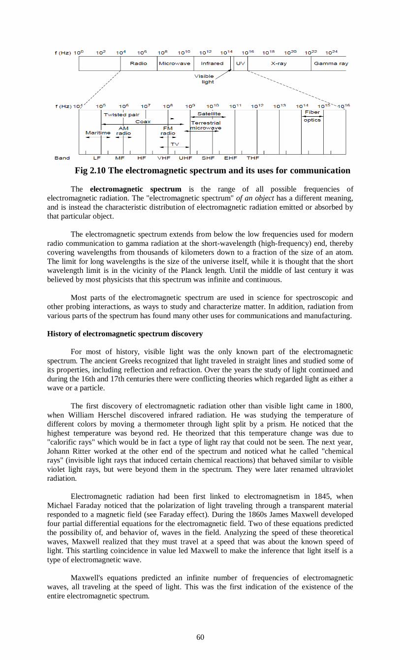
60
Fig 2.10 The electromagnetic spectrum and its uses for communication
The electromagnetic spectrum is the range of all possible frequencies of
electromagnetic radiation. The "electromagnetic spectrum" of an object has a different meaning,
and is instead the characteristic distribution of electromagnetic radiation emitted or absorbed by
that particular object.
The electromagnetic spectrum extends from below the low frequencies used for modern
radio communication to gamma radiation at the short-wavelength (high-frequency) end, thereby
covering wavelengths from thousands of kilometers down to a fraction of the size of an atom.
The limit for long wavelengths is the size of the universe itself, while it is thought that the short
wavelength limit is in the vicinity of the Planck length. Until the middle of last century it was
believed by most physicists that this spectrum was infinite and continuous.
Most parts of the electromagnetic spectrum are used in science for spectroscopic and
other probing interactions, as ways to study and characterize matter. In addition, radiation from
various parts of the spectrum has found many other uses for communications and manufacturing.
History of electromagnetic spectrum discovery
For most of history, visible light was the only known part of the electromagnetic
spectrum. The ancient Greeks recognized that light traveled in straight lines and studied some of
its properties, including reflection and refraction. Over the years the study of light continued and
during the 16th and 17th centuries there were conflicting theories which regarded light as either a
wave or a particle.
The first discovery of electromagnetic radiation other than visible light came in 1800,
when William Herschel discovered infrared radiation. He was studying the temperature of
different colors by moving a thermometer through light split by a prism. He noticed that the
highest temperature was beyond red. He theorized that this temperature change was due to
"calorific rays" which would be in fact a type of light ray that could not be seen. The next year,
Johann Ritter worked at the other end of the spectrum and noticed what he called "chemical
rays" (invisible light rays that induced certain chemical reactions) that behaved similar to visible
violet light rays, but were beyond them in the spectrum. They were later renamed ultraviolet
radiation.
Electromagnetic radiation had been first linked to electromagnetism in 1845, when
Michael Faraday noticed that the polarization of light traveling through a transparent material
responded to a magnetic field (see Faraday effect). During the 1860s James Maxwell developed
four partial differential equations for the electromagnetic field. Two of these equations predicted
the possibility of, and behavior of, waves in the field. Analyzing the speed of these theoretical
waves, Maxwell realized that they must travel at a speed that was about the known speed of
light. This startling coincidence in value led Maxwell to make the inference that light itself is a
type of electromagnetic wave.
Maxwell's equations predicted an infinite number of frequencies of electromagnetic
waves, all traveling at the speed of light. This was the first indication of the existence of the
entire electromagnetic spectrum.

61
Maxwell's predicted waves included waves at very low frequencies compared to infrared,
which in theory might be created by oscillating charges in an ordinary electrical circuit of a
certain type.
Attempting to prove Maxwell's equations and detect such low frequency electromagnetic
radiation, in 1886 the physicist Heinrich Hertz built an apparatus to generate and detect what is
now called radio waves.
Hertz found the waves and was able to infer (by measuring their wavelength and
multiplying it by their frequency) that they traveled at the speed of light. Hertz also demonstrated
that the new radiation could be both reflected and refracted by various dielectric media, in the
same manner as light. For example, Hertz was able to focus the waves using a lens made of tree
resin. In a later experiment, Hertz similarly produced and measured the properties of
microwaves. These new types of waves paved the way for inventions such as the wireless
telegraph and the radio.
In 1895 Wilhelm Röntgen noticed a new type of radiation emitted during an experiment
with an evacuated tube subjected to a high voltage. He called these radiations x-rays and found
that they were able to travel through parts of the human body but were reflected or stopped by
denser matter such as bones. Before long, many uses were found for them in the field of
medicine.
The last portion of the electromagnetic spectrum was filled in with the discovery of
gamma rays. In 1900 Paul Villard was studying the radioactive emissions of radium when he
identified a new type of radiation that he first thought consisted of particles similar to known
alpha and beta particles, but with the power of being far more penetrating than either. However,
in 1910, British physicist William Henry Bragg demonstrated that gamma rays are
electromagnetic radiation, not particles, and in 1914, Ernest Rutherford (who had named them
gamma rays in 1903 when he realized that they were fundamentally different from charged alpha
and beta rays) and Edward Andrade measured their wavelengths, and found that gamma rays
were similar to X-rays, but with shorter wavelengths and higher frequencies.
Radio Transmission
Radio waves are very easy to generate andcan penetrate buildings easily, can travel long
distances because of which they can be used for communication indoor and outdoor both. Radio
waves travel in all the direction from the source because of which physical alignment of
transmitter and receiver is not important.
The property of radio waves varies as the frequency varies.Radio waves pass through
obstacles well at low frequencies,but the power falls roughly as 1/r2with distance from the
source, in air. Radio waves tend to travel in straight lines at high frequenciesand bounce off
obstacles but are also absorbed by rain. At allfrequencies, radio waves are subject to interference
from motors and other electrical equipment.
In the VLF, LF, and MF bands, radio waves follow the ground, as shown in figure. These
waves can bedetected for perhaps 1000 km at the lower frequencies, less at the higher ones. AM
radio broadcasting uses theMF band, which is why the ground wavescannot be heard easily in
New York from Boston AM radio stations.Radio waves in these bands pass through buildings
easily, that’s why portable radios work indoors. Low bandwidth is the mainproblem for using
these bands for data communication.
In the VLF, LF, and MF bands, radio waves follow the curvature of the earth. (B) In the
HFband, they bounce off the ionosphere.
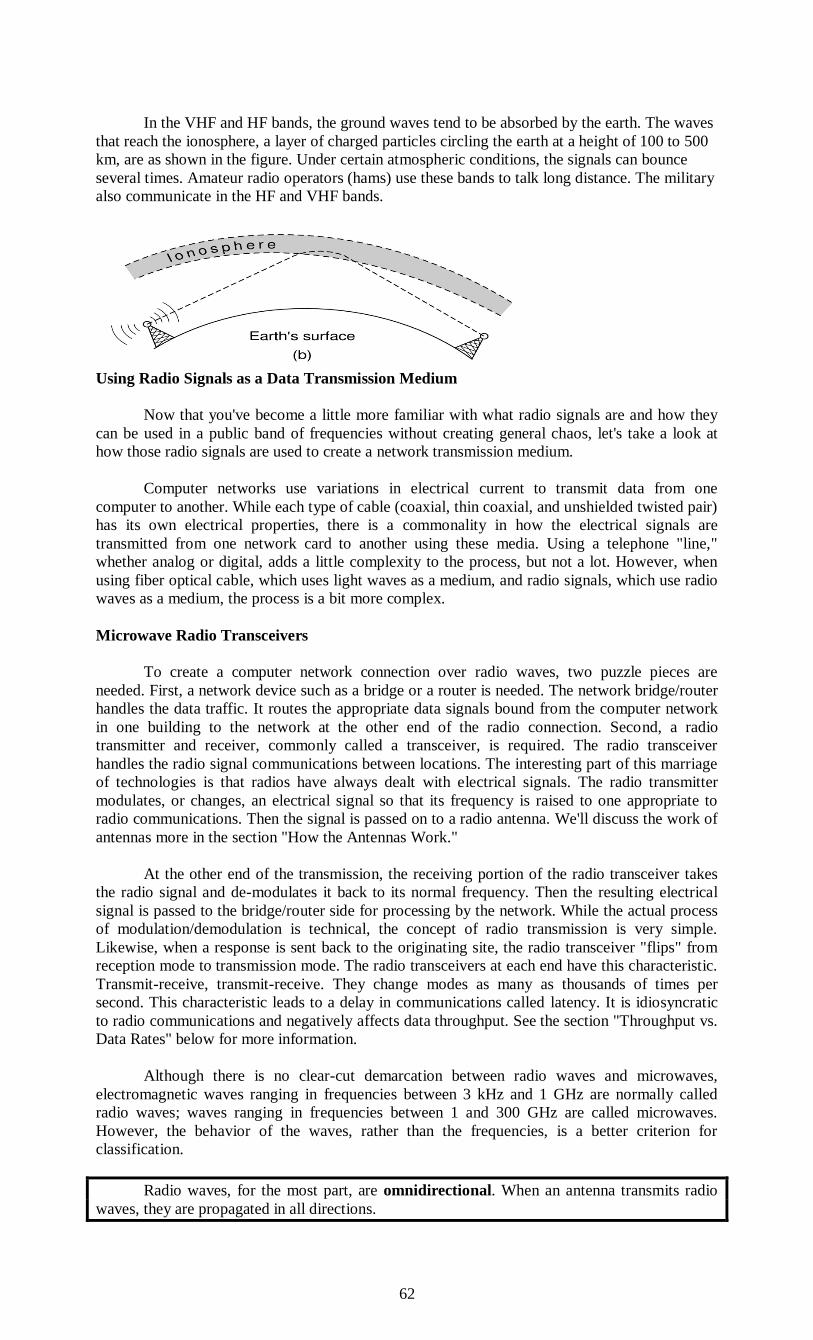
62
In the VHF and HF bands, the ground waves tend to be absorbed by the earth. The waves
that reach the ionosphere, a layer of charged particles circling the earth at a height of 100 to 500
km, are as shown in the figure. Under certain atmospheric conditions, the signals can bounce
several times. Amateur radio operators (hams) use these bands to talk long distance. The military
also communicate in the HF and VHF bands.
Using Radio Signals as a Data Transmission Medium
Now that you've become a little more familiar with what radio signals are and how they
can be used in a public band of frequencies without creating general chaos, let's take a look at
how those radio signals are used to create a network transmission medium.
Computer networks use variations in electrical current to transmit data from one
computer to another. While each type of cable (coaxial, thin coaxial, and unshielded twisted pair)
has its own electrical properties, there is a commonality in how the electrical signals are
transmitted from one network card to another using these media. Using a telephone "line,"
whether analog or digital, adds a little complexity to the process, but not a lot. However, when
using fiber optical cable, which uses light waves as a medium, and radio signals, which use radio
waves as a medium, the process is a bit more complex.
Microwave Radio Transceivers
To create a computer network connection over radio waves, two puzzle pieces are
needed. First, a network device such as a bridge or a router is needed. The network bridge/router
handles the data traffic. It routes the appropriate data signals bound from the computer network
in one building to the network at the other end of the radio connection. Second, a radio
transmitter and receiver, commonly called a transceiver, is required. The radio transceiver
handles the radio signal communications between locations. The interesting part of this marriage
of technologies is that radios have always dealt with electrical signals. The radio transmitter
modulates, or changes, an electrical signal so that its frequency is raised to one appropriate to
radio communications. Then the signal is passed on to a radio antenna. We'll discuss the work of
antennas more in the section "How the Antennas Work."
At the other end of the transmission, the receiving portion of the radio transceiver takes
the radio signal and de-modulates it back to its normal frequency. Then the resulting electrical
signal is passed to the bridge/router side for processing by the network. While the actual process
of modulation/demodulation is technical, the concept of radio transmission is very simple.
Likewise, when a response is sent back to the originating site, the radio transceiver "flips" from
reception mode to transmission mode. The radio transceivers at each end have this characteristic.
Transmit-receive, transmit-receive. They change modes as many as thousands of times per
second. This characteristic leads to a delay in communications called latency. It is idiosyncratic
to radio communications and negatively affects data throughput. See the section "Throughput vs.
Data Rates" below for more information.
Although there is no clear-cut demarcation between radio waves and microwaves,
electromagnetic waves ranging in frequencies between 3 kHz and 1 GHz are normally called
radio waves; waves ranging in frequencies between 1 and 300 GHz are called microwaves.
However, the behavior of the waves, rather than the frequencies, is a better criterion for
classification.
Radio waves, for the most part, are omnidirectional. When an antenna transmits radio
waves, they are propagated in all directions.
63
This means that the sending and receiving antennas do not have to be aligned. A sending
antenna sends waves that can be received by any receiving antenna. The omnidirectional
property has a disadvantage, too. The radio waves transmitted by one antenna are susceptible to
interference by another antenna that may send signals using the same frequency or band. Radio
waves,in the sky mode,can travel long distances.
Microwave Transmission
Above 100 MHz, the waves travel in nearly straight lines and can therefore be narrowly
focused. Concentrating all the energy into a small beam by means of a parabolic antenna (like
the familiar satellite TV dish) gives a much higher signal-to-noise ratio, but the transmitting and
receiving antennas must be accurately aligned with each other.
In addition, this directionality allows multiple transmitters lined up in arow to
communicate with multiple receivers in a row without interference, provided some minimum
spacing rules are observed. Before fiber optics, for decades these microwaves formed the heart of
the long-distance telephone transmission system. In fact, MCI, one of AT&T’s first competitors
after it was deregulated, built its entire system with microwave communications passing between
towers tens of kilometers apart. Even the company’s name reflected this (MCI stood for
Microwave Communications, Inc.). MCI has since gone over to fiber and through a long series
of corporate mergers and bankruptcies in the telecommunications shuffle has become part of
Verizon
Microwaves travel in a straight line, so if the towers are too far apart, the earth will get in
the way (think about a Seattle-to-Amsterdam link). Thus, repeaters are needed periodically. The
higher the towers are, the farther apart they can be. The distance between repeaters goes up very
roughly with the square root of the tower height. For 100-meter-high towers, repeaters can be 80
km apart.Unlike radio waves at lower frequencies, microwaves do not pass through buildings
well. In addition, even though the beam may be well focused at the transmitter, there is still some
divergence in space. Some waves may be refracted off low-lying atmospheric layers and may
take slightly longer to arrive than the direct waves.
The delayed waves may arrive out of phase with the direct wave and thus cancel the
signal. This effect is called multipath fading and is often a serious problem. It is weather and
frequency dependent. Some operators keep 10% of their channels idle as spares to switch on
when multipath fading temporarily wipes out some frequency band.
The demand for more and more spectrum drives operators to yet higher frequencies. Bands up to
10 GHz are now in routine use, but at about 4 GHz a new problem sets in: absorption by water.
These waves are only a few centimeters long and are absorbed by rain. This effect would be fine
if one were planning to build a huge outdoor microwave oven for roasting passing birds, but for
communication it is a severe problem. As with multipath fading, the only solution is to shut off
links that are being rained on and route around them.
In summary, microwave communication is so widely used for long-distance telephone
communication, mobile phones, television distribution, and other purposes that a severe shortage
of spectrum has developed. It has several key advantages over fiber. The main one is that no
right of way is needed to lay down cables. By buying a small plot of ground every 50 km and
putting a microwave tower on it, one can bypass the telephone system entirely.
This is how MCI managed to get started as a new long-distance telephone company so
quickly. (Sprint,another early competitor to the deregulated AT&T, went a completely different
route: it was formed by the Southern Pacific Railroad, which already owned a large amount of
right of way and just buried fiber next to the tracks.) Microwave is also relatively inexpensive.
Putting up two simple towers (which can be just big poles with four guy wires) and putting
antennas on each one may be cheaper than burying 50 km of fiber through a congested urban
area or up over a mountain, and it may also be cheaper than leasing the telephone company’s
fiber, especially if the telephone company has not yet even fully paid for the copper it ripped out
when it put in the fiber.
Infrared Transmission

64
Unguided infrared waves are widely used for short-range communication.The remote
controls used for televisions, VCRs, and stereos all use infrared communication. They are
relatively directional, cheap, and easy to build but have a major drawback: they do not pass
through solid objects. (Try standing between your remote control and your television and see if it
still works.) In general, as we go from long-wave radio toward visible light, the waves behave
more and more like light and less and less like radio.
On the other hand, the fact that infrared waves do not pass through solid walls well is also
a plus. It means that an infrared system in one room of a building will not interfere with a similar
system in adjacent rooms or buildings: you cannot control your neighbor’s television with your
remote control. Furthermore, security of infrared systems against eavesdropping is better than
that of radio systems precisely for this reason. Therefore, no government license is needed to
operate an infrared system, in contrast to radio systems, which must be licensed outside the ISM
bands.
Infrared communication has a limited use on the desktop, for example, to connect
notebook computers and printers with the IrDA(Infrared Data Association ) standard, but it is not
a major player in the communication game.
Infrared reflectography (fr/it/es), as called by art historians, are taken of paintings to
reveal underlying layers, in particular the underdrawing or outline drawn by the artist as a guide.
This often uses carbon black, which shows up well in reflectograms, as long as it has not also
been used in the ground underlying the whole painting. Art historians are looking to see whether
the visible layers of paint differ from the under-drawing or layers in between – such alterations
are called pentimenti when made by the original artist. This is very useful information in
deciding whether a painting is the prime version by the original artist or a copy, and whether it
has been altered by over-enthusiastic restoration work. In general, the more pentimenti the more
likely a painting is to be the prime version. It also gives useful insights into working practices.
Among many other changes in the Arnolfini Portrait of 1434 (left), the man's face was
originally higher by about the height of his eye; the woman's was higher, and her eyes looked
more to the front. Each of his feet was underdrawn in one position, painted in another, and then
overpainted in a third. These alterations are seen in infra-red reflectograms.
Similar uses of infrared are made by historians on various types of objects, especially
very old written documents such as the Dead Sea Scrolls, the Roman works in the Villa of the
Papyri, and the Silk Road texts found in the Dunhuang Caves. Carbon black used in ink can
show up extremely well.
Biological systems
Thermographic image of a snake eating a mouse Thermographic image of a fruit bat.The
pit viper has a pair of infrared sensory pits on its head. There is uncertainty regarding the exact
thermal sensitivity of this biological infrared detection system.Other organisms that have
thermoreceptive organs are pythons (family Pythonidae), some boas (family Boidae), the
Common Vampire Bat (Desmodus rotundus), a variety of jewel beetles (Melanophila acuminata)
darkly pigmented butterflies (Pachliopta aristolochiae and Troides rhadamantus plateni), and
possibly blood-sucking bugs (Triatoma infestans).
Although near-infrared vision (780–1000 nm) has long been deemed impossible due to
noise in visual pigments, sensation of near-infrared light was reported in the common carp and in
three cichlid species. Fish use NIR to capture prey and for phototactic swimming orientation.
NIR sensation in fish may be relevant under poor lighting conditions during twilight and in turbid
surface waters.
Photobiomodulation
Near-infrared light, or photobiomodulation, is used for treatment of chemotherapy-
induced oral ulceration as well as wound healing. There is some work relating to anti-herpes
virus treatment. Research projects include work on central nervous system healing effects via
cytochrome c oxidase upregulation and other possible mechanisms.
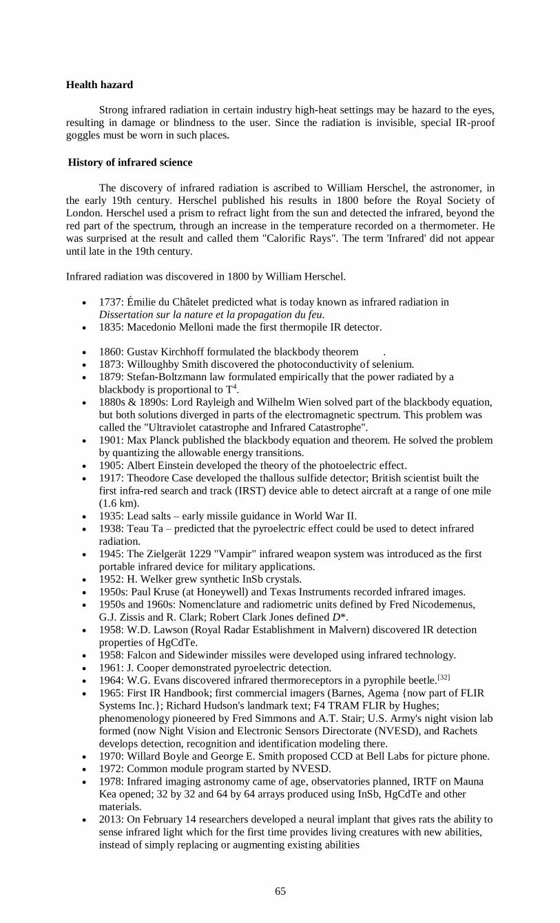
65
Health hazard
Strong infrared radiation in certain industry high-heat settings may be hazard to the eyes,
resulting in damage or blindness to the user. Since the radiation is invisible, special IR-proof
goggles must be worn in such places.
History of infrared science
The discovery of infrared radiation is ascribed to William Herschel, the astronomer, in
the early 19th century. Herschel published his results in 1800 before the Royal Society of
London. Herschel used a prism to refract light from the sun and detected the infrared, beyond the
red part of the spectrum, through an increase in the temperature recorded on a thermometer. He
was surprised at the result and called them "Calorific Rays". The term 'Infrared' did not appear
until late in the 19th century.
Infrared radiation was discovered in 1800 by William Herschel.
1737: Émilie du Châtelet predicted what is today known as infrared radiation in
Dissertation sur la nature et la propagation du feu.
1835: Macedonio Melloni made the first thermopile IR detector.
1860: Gustav Kirchhoff formulated the blackbody theorem .
1873: Willoughby Smith discovered the photoconductivity of selenium.
1879: Stefan-Boltzmann law formulated empirically that the power radiated by a
blackbody is proportional to T4.
1880s & 1890s: Lord Rayleigh and Wilhelm Wien solved part of the blackbody equation,
but both solutions diverged in parts of the electromagnetic spectrum. This problem was
called the "Ultraviolet catastrophe and Infrared Catastrophe".
1901: Max Planck published the blackbody equation and theorem. He solved the problem
by quantizing the allowable energy transitions.
1905: Albert Einstein developed the theory of the photoelectric effect.
1917: Theodore Case developed the thallous sulfide detector; British scientist built the
first infra-red search and track (IRST) device able to detect aircraft at a range of one mile
(1.6 km).
1935: Lead salts – early missile guidance in World War II.
1938: Teau Ta – predicted that the pyroelectric effect could be used to detect infrared
radiation.
1945: The Zielgerät 1229 "Vampir" infrared weapon system was introduced as the first
portable infrared device for military applications.
1952: H. Welker grew synthetic InSb crystals.
1950s: Paul Kruse (at Honeywell) and Texas Instruments recorded infrared images.
1950s and 1960s: Nomenclature and radiometric units defined by Fred Nicodemenus,
G.J. Zissis and R. Clark; Robert Clark Jones defined D*.
1958: W.D. Lawson (Royal Radar Establishment in Malvern) discovered IR detection
properties of HgCdTe.
1958: Falcon and Sidewinder missiles were developed using infrared technology.
1961: J. Cooper demonstrated pyroelectric detection.
1964: W.G. Evans discovered infrared thermoreceptors in a pyrophile beetle.[32]
1965: First IR Handbook; first commercial imagers (Barnes, Agema {now part of FLIR
Systems Inc.}; Richard Hudson's landmark text; F4 TRAM FLIR by Hughes;
phenomenology pioneered by Fred Simmons and A.T. Stair; U.S. Army's night vision lab
formed (now Night Vision and Electronic Sensors Directorate (NVESD), and Rachets
develops detection, recognition and identification modeling there.
1970: Willard Boyle and George E. Smith proposed CCD at Bell Labs for picture phone.
1972: Common module program started by NVESD.
1978: Infrared imaging astronomy came of age, observatories planned, IRTF on Mauna
Kea opened; 32 by 32 and 64 by 64 arrays produced using InSb, HgCdTe and other
materials.
2013: On February 14 researchers developed a neural implant that gives rats the ability to
sense infrared light which for the first time provides living creatures with new abilities,
instead of simply replacing or augmenting existing abilities

66
Lightwave Transmission
Unguided optical signaling or free-space optics has been in use for centuries. Paul Revere
used binary optical signaling from the Old North Church just prior to his famous ride. A more
modern application is to connect the LANs in two buildings via lasers mounted on their rooftops.
Optical signaling using lasers is inherently unidirectional, so each end needs its own laser and its
own photodetector. This scheme offers very high bandwidth at very low cost and is relatively
secure because it is difficult to tap a narrow laser beam. It is also relatively easy to install and,
unlike microwave transmission, does not require an FCC license.
The laser’s strength, a very narrow beam, is also its weakness here.
Aiming a laser beam 1 mm wide at a target the size of a pin head 500 meters away
requires the marksmanship of a latter-day Annie Oakley.
Usually, lenses are put into the system to defocus the beam slightly. To add to the
difficulty, wind and temperature changes can distort the beam and laser beams also cannot
penetrate rain or thick fog, although they normally work well on sunny days. However, many of
these factors are not an issue when the use is to connect two spacecraft.
One of the authors (AST) once attended a conference at a modern hotel in Europe at
which the conference organizers thoughtfully provided a room full of terminals to allow the
attendees to read their email during boring presentations. Since the local PTT was unwilling to
install a large number of telephone lines for just 3 days, the organizers put a laser on the roof and
aimed it at their university’s computer science building a few kilometers away. They tested it the
night before the conference and it worked perfectly. At 9A.M.on a bright, sunny day, the link
failed completely and stayed down all day. The pattern repeated itself the next two days. It was
not until after the conference that the organizers discovered the problem: heat from the sun
during the daytime caused convection currents to rise up from the roof of the building, as shown
in Fig.
This turbulent air diverted the beam and made it dance around the detector, much like a
shimmering road on a hot day. The lesson here is that to work well in difficult conditions as well
as good conditions, unguided optical links need to be engineered with a sufficient margin of error
Unguided optical communication may seem like an exotic networking technology today, but it
might soon become much more prevalent. We are surrounded by cameras (that sense light) and
displays (that emit light using LEDs and other technology). Data communication can be layered
on top of these displays by encoding information in the pattern at which LEDs turn on and off
that is below the threshold of human perception. Communicating with visible light in this way is
inherently safe and creates a low-speed network in the immediate vicinity of the display. This
could enable all sorts of fanciful ubiquitous computing scenarios.
The flashing lights on emergency vehicles might alert nearby traffic lights and vehicles to help
clear a path. Informational signs might broadcast maps. Even festive lights might broadcast
songs that are synchronized with their display.
Communication Satellites
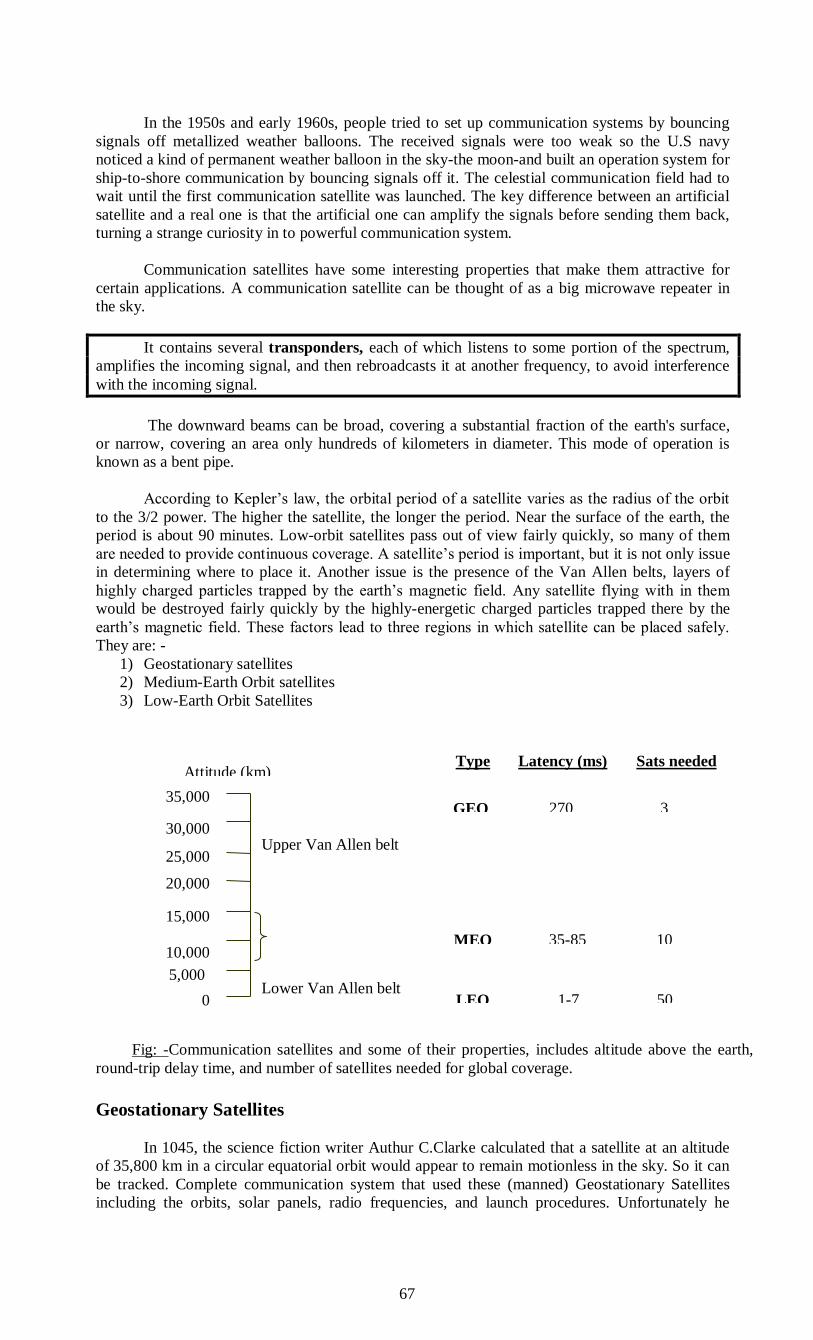
67
In the 1950s and early 1960s, people tried to set up communication systems by bouncing
signals off metallized weather balloons. The received signals were too weak so the U.S navy
noticed a kind of permanent weather balloon in the sky-the moon-and built an operation system for
ship-to-shore communication by bouncing signals off it. The celestial communication field had to
wait until the first communication satellite was launched. The key difference between an artificial
satellite and a real one is that the artificial one can amplify the signals before sending them back,
turning a strange curiosity in to powerful communication system.
Communication satellites have some interesting properties that make them attractive for
certain applications. A communication satellite can be thought of as a big microwave repeater in
the sky.
It contains several transponders, each of which listens to some portion of the spectrum,
amplifies the incoming signal, and then rebroadcasts it at another frequency, to avoid interference
with the incoming signal.
The downward beams can be broad, covering a substantial fraction of the earth's surface,
or narrow, covering an area only hundreds of kilometers in diameter. This mode of operation is
known as a bent pipe.
According to Kepler’s law, the orbital period of a satellite varies as the radius of the orbit
to the 3/2 power. The higher the satellite, the longer the period. Near the surface of the earth, the
period is about 90 minutes. Low-orbit satellites pass out of view fairly quickly, so many of them
are needed to provide continuous coverage. A satellite’s period is important, but it is not only issue
in determining where to place it. Another issue is the presence of the Van Allen belts, layers of
highly charged particles trapped by the earth’s magnetic field. Any satellite flying with in them
would be destroyed fairly quickly by the highly-energetic charged particles trapped there by the
earth’s magnetic field. These factors lead to three regions in which satellite can be placed safely.
They are: -
1) Geostationary satellites
2) Medium-Earth Orbit satellites
3) Low-Earth Orbit Satellites
Fig: -Communication satellites and some of their properties, includes altitude above the earth,
round-trip delay time, and number of satellites needed for global coverage.
Geostationary Satellites
In 1045, the science fiction writer Authur C.Clarke calculated that a satellite at an altitude
of 35,800 km in a circular equatorial orbit would appear to remain motionless in the sky. So it can
be tracked. Complete communication system that used these (manned) Geostationary Satellites
including the orbits, solar panels, radio frequencies, and launch procedures. Unfortunately he
35,000
30,000
25,000
20,000
15,000
10,000
5,000
0
Attitude (km) Type Latency (ms) Sats needed
Upper Van Allen belt
Lower Van Allen belt
GEO
MEO
LEO
270 3
35-85 10
1-7 50
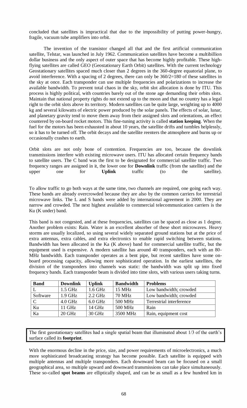
68
concluded that satellites is impractical that due to the impossibility of putting power-hungry,
fragile, vacuum tube amplifiers into orbit.
The invention of the transistor changed all that and the first artificial communication
satellite, Telstar, was launched in July 1962. Communication satellites have become a multibillion
dollar business and the only aspect of outer space that has become highly profitable. These high-
flying satellites are called GEO (Geostationary Earth Orbit) satellites. With the current technology
Geostationary satellites spaced much closer than 2 degrees in the 360-degree equatorial plane, to
avoid interference. With a spacing of 2 degrees, there can only be 360/2=180 of these satellites in
the sky at once. Each transponder can use multiple frequencies and polarizations to increase the
available bandwidth. To prevent total chaos in the sky, orbit slot allocation is done by ITU. This
process is highly political, with countries barely out of the stone age demanding their orbits slots.
Maintain that national property rights do not extend up to the moon and that no country has a legal
right to the orbit slots above its territory. Modern satellites can be quite large, weighting up to 4000
kg and several kilowatts of electric power produced by the solar panels. The effects of solar, lunar,
and planetary gravity tend to move them away from their assigned slots and orientations, an effect
countered by on-board rocket motors. This fine-tuning activity is called station keeping. When the
fuel for the motors has been exhausted in about 10 years, the satellite drifts and tumbles helplessly,
so it has to be turned off. The orbit decays and the satellite reenters the atmosphere and burns up or
occasionally crashes to earth.
Orbit slots are not only bone of contention. Frequencies are too, because the downlink
transmissions interfere with existing microwave users. ITU has allocated certain frequency bands
to satellite users. The C band was the first to be designated for commercial satellite traffic. Two
frequency ranges are assigned in it, the lower one for Downlink traffic (from the satellite) and the
upper one for Uplink traffic (to the satellite).
To allow traffic to go both ways at the same time, two channels are required, one going each way.
These bands are already overcrowded because they are also by the common carriers for terrestrial
microwave links. The L and S bands were added by international agreement in 2000. They are
narrow and crowded. The next highest available to commercial telecommunication carriers is the
Ku (K under) band.
This band is not congested, and at these frequencies, satellites can be spaced as close as 1 degree.
Another problem exists: Rain. Water is an excellent absorber of these short microwaves. Heavy
storms are usually localized, so using several widely separated ground stations but at the price of
extra antennas, extra cables, and extra electronics to enable rapid switching between stations.
Bandwidth has been allocated in the Ka (K above) band for commercial satellite traffic, but the
equipment used is expensive. A modern satellite has around 40 transponders, each with an 80-
MHz bandwidth. Each transponder operates as a bent pipe, but recent satellites have some on-
board processing capacity, allowing more sophisticated operation. In the earliest satellites, the
division of the transponders into channels was static: the bandwidth was split up into fixed
frequency bands. Each transponder beam is divided into time slots, with various users taking turns.
Band Downlink Uplink Bandwidth Problems
L 1.5 GHz 1.6 GHz 15 MHz Low bandwidth; crowded
Software 1.9 GHz 2.2 GHz 70 MHz Low bandwidth; crowded
C 4.0 GHz 6.0 GHz 500 MHz Terrestrial interference
Ku 11 GHz 14 GHz 500 MHz Rain
Ka 20 GHz 30 GHz 3500 MHz Rain, equipment cost
The first geostationary satellites had a single spatial beam that illuminated about 1/3 of the earth’s
surface called its footprint.
With the enormous decline in the price, size, and power requirements of microelectronics, a much
more sophisticated broadcasting strategy has become possible. Each satellite is equipped with
multiple antennas and multiple transponders. Each downward beam can be focused on a small
geographical area, so multiple upward and downward transmissions can take place simultaneously.
These so-called spot beams are elliptically shaped, and can be as small as a few hundred km in
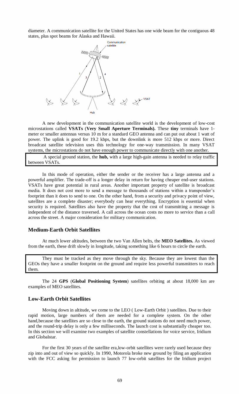
69
diameter. A communication satellite for the United States has one wide beam for the contiguous 48
states, plus spot beams for Alaska and Hawaii.
A new development in the communication satellite world is the development of low-cost
microstations called VSATs (Very Small Aperture Terminals). These tiny terminals have 1-
meter or smaller antennas versus 10 m for a standard GEO antenna and can put out about 1 watt of
power. The uplink is good for 19.2 kbps, but the downlink is more 512 kbps or more. Direct
broadcast satellite television uses this technology for one-way transmission. In many VSAT
systems, the microstations do not have enough power to communicate directly with one another.
A special ground station, the hub, with a large high-gain antenna is needed to relay traffic
between VSATs.
In this mode of operation, either the sender or the receiver has a large antenna and a
powerful amplifier. The trade-off is a longer delay in return for having cheaper end-user stations.
VSATs have great potential in rural areas. Another important property of satellite is broadcast
media. It does not cost more to send a message to thousands of stations within a transponder’s
footprint than it does to send to one. On the other hand, from a security and privacy point of view,
satellites are a complete disaster; everybody can hear everything. Encryption is essential when
security is required. Satellites also have the property that the cost of transmitting a message is
independent of the distance traversed. A call across the ocean costs no more to service than a call
across the street. A major consideration for military communication.
Medium-Earth Orbit Satellites
At much lower altitudes, between the two Van Allen belts, the MEO Satellites. As viewed
from the earth, these drift slowly in longitude, taking something like 6 hours to circle the earth.
They must be tracked as they move through the sky. Because they are lowest than the
GEOs they have a smaller footprint on the ground and require less powerful transmitters to reach
them.
The 24 GPS (Global Positioning System) satellites orbiting at about 18,000 km are
examples of MEO satellites.
Low-Earth Orbit Satellites
Moving down in altitude, we come to the LEO ( Low-Earth Orbit ) satellites. Due to their
rapid motion, large numbers of them are needed for a complete system. On the other
hand,because the satellites are so close to the earth, the ground stations do not need much power,
and the round-trip delay is only a few milliseconds. The launch cost is substantially cheaper too.
In this section we will examine two examples of satellite constellations for voice service, Iridium
and Globalstar.
For the first 30 years of the satellite era,low-orbit satellites were rarely used because they
zip into and out of view so quickly. In 1990, Motorola broke new ground by filing an application
with the FCC asking for permission to launch 77 low-orbit satellites for the Iridium project
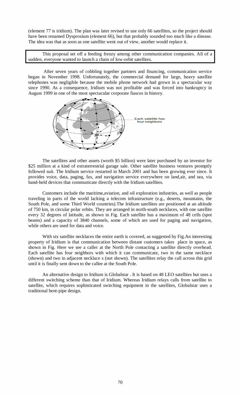
70
(element 77 is iridium). The plan was later revised to use only 66 satellites, so the project should
have been renamed Dysprosium (element 66), but that probably sounded too much like a disease.
The idea was that as soon as one satellite went out of view, another would replace it.
This proposal set off a feeding frenzy among other communication companies. All of a
sudden, everyone wanted to launch a chain of low-orbit satellites.
After seven years of cobbling together partners and financing, communication service
began in November 1998. Unfortunately, the commercial demand for large, heavy satellite
telephones was negligible because the mobile phone network had grown in a spectacular way
since 1990. As a consequence, Iridium was not profitable and was forced into bankruptcy in
August 1999 in one of the most spectacular corporate fiascos in history.
The satellites and other assets (worth $5 billion) were later purchased by an investor for
$25 million at a kind of extraterrestrial garage sale. Other satellite business ventures promptly
followed suit. The Iridium service restarted in March 2001 and has been growing ever since. It
provides voice, data, paging, fax, and navigation service everywhere on land,air, and sea, via
hand-held devices that communicate directly with the Iridium satellites.
Customers include the maritime,aviation, and oil exploration industries, as well as people
traveling in parts of the world lacking a telecom infrastructure (e.g., deserts, mountains, the
South Pole, and some Third World countries).The Iridium satellites are positioned at an altitude
of 750 km, in circular polar orbits. They are arranged in north-south necklaces, with one satellite
every 32 degrees of latitude, as shown in Fig. Each satellite has a maximum of 48 cells (spot
beams) and a capacity of 3840 channels, some of which are used for paging and navigation,
while others are used for data and voice.
With six satellite necklaces the entire earth is covered, as suggested by Fig.An interesting
property of Iridium is that communication between distant customers takes place in space, as
shown in Fig. Here we see a caller at the North Pole contacting a satellite directly overhead.
Each satellite has four neighbors with which it can communicate, two in the same necklace
(shown) and two in adjacent necklace s (not shown). The satellites relay the call across this grid
until it is finally sent down to the callee at the South Pole.
An alternative design to Iridium is Globalstar . It is based on 48 LEO satellites but uses a
different switching scheme than that of Iridium. Whereas Iridium relays calls from satellite to
satellite, which requires sophisticated switching equipment in the satellites, Globalstar uses a
traditional bent-pipe design.
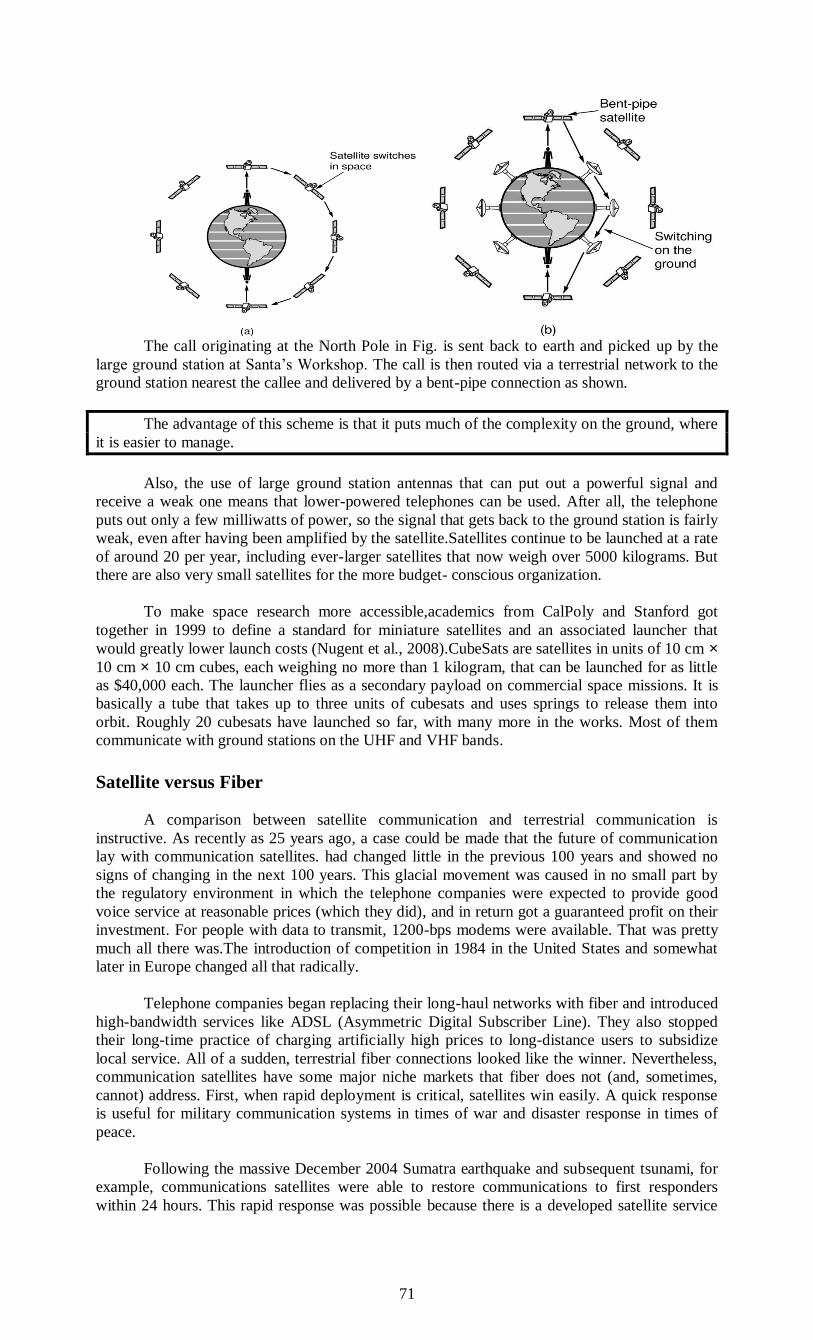
71
The call originating at the North Pole in Fig. is sent back to earth and picked up by the
large ground station at Santa’s Workshop. The call is then routed via a terrestrial network to the
ground station nearest the callee and delivered by a bent-pipe connection as shown.
The advantage of this scheme is that it puts much of the complexity on the ground, where
it is easier to manage.
Also, the use of large ground station antennas that can put out a powerful signal and
receive a weak one means that lower-powered telephones can be used. After all, the telephone
puts out only a few milliwatts of power, so the signal that gets back to the ground station is fairly
weak, even after having been amplified by the satellite.Satellites continue to be launched at a rate
of around 20 per year, including ever-larger satellites that now weigh over 5000 kilograms. But
there are also very small satellites for the more budget- conscious organization.
To make space research more accessible,academics from CalPoly and Stanford got
together in 1999 to define a standard for miniature satellites and an associated launcher that
would greatly lower launch costs (Nugent et al., 2008).CubeSats are satellites in units of 10 cm × 10 cm × 10 cm cubes, each weighing no more than 1 kilogram, that can be launched for as little
as $40,000 each. The launcher flies as a secondary payload on commercial space missions. It is
basically a tube that takes up to three units of cubesats and uses springs to release them into
orbit. Roughly 20 cubesats have launched so far, with many more in the works. Most of them
communicate with ground stations on the UHF and VHF bands.
Satellite versus Fiber
A comparison between satellite communication and terrestrial communication is
instructive. As recently as 25 years ago, a case could be made that the future of communication
lay with communication satellites. had changed little in the previous 100 years and showed no
signs of changing in the next 100 years. This glacial movement was caused in no small part by
the regulatory environment in which the telephone companies were expected to provide good
voice service at reasonable prices (which they did), and in return got a guaranteed profit on their
investment. For people with data to transmit, 1200-bps modems were available. That was pretty
much all there was.The introduction of competition in 1984 in the United States and somewhat
later in Europe changed all that radically.
Telephone companies began replacing their long-haul networks with fiber and introduced
high-bandwidth services like ADSL (Asymmetric Digital Subscriber Line). They also stopped
their long-time practice of charging artificially high prices to long-distance users to subsidize
local service. All of a sudden, terrestrial fiber connections looked like the winner. Nevertheless,
communication satellites have some major niche markets that fiber does not (and, sometimes,
cannot) address. First, when rapid deployment is critical, satellites win easily. A quick response
is useful for military communication systems in times of war and disaster response in times of
peace.
Following the massive December 2004 Sumatra earthquake and subsequent tsunami, for
example, communications satellites were able to restore communications to first responders
within 24 hours. This rapid response was possible because there is a developed satellite service
72
provider market in which large players, such as Intelsat with over 50 satellites, can rent out
capacity pretty much anywhere it is needed.
For customers served by existing satellite networks, a VSAT can be set up easily and
quickly to provide a megabit/sec link to elsewhere in the world.
A second niche is for communication in places where the terrestrial infra structure is
poorly developed. Many people nowadays want to communicate everywhere they go. Mobile
phone networks cover those locations with good population density, but do not do an adequate
job in other places (e.g., at sea or in the desert).
Conversely, Iridium provides voice service everywhere on Earth, even at the South Pole.
Terrestrial infrastructure can also be expensive to install,depending on the terrain and necessary
rights of way. Indonesia, for example, has its own satellite for domestic telephone traffic.
Launching one satellite was cheaper than stringing thousands of undersea cables among the
13,677 islands in the archipelago. A third niche is when broadcasting is essential.
A message sent by satellite can be received by thousands of ground stations at once.
Satellites are used to distribute much network TV programming to local stations for this reason.
There is now a large market for satellite broadcasts of digital TV and radio directly to end users
with satellite receivers in their homes and cars. All sorts of other content can be broadcast too.
For example, an organization transmitting a stream of stock, bond, or commodity prices to
thousands of dealers might find a satellite system to be much cheaper than simulating
broadcasting on the ground. In short, it looks like the mainstream communication of the future
will be terrestrial fiber optics combined with cellular radio, but for some specialized uses,
satellites are better.
However, there is one caveat that applies to all of this: economics. Although fiber offers
more bandwidth, it is conceivable that terrestrial and satellite communication could compete
aggressively on price. If advances in technology radically cut the cost of deploying a satellite
(e.g.,if some future space vehicle can toss out dozens of satellites on one launch) or low-orbit
satellites catch on in a big way, it is not certain that fiber will win all markets.
HUB
An Ethernet hub, active hub, network hub, repeater hub, multiport repeater or hub
is a device for connecting multiple Ethernet devices together and making them act as a single
network segment. It has multiple input/output (I/O) ports, in which a signal introduced at the
input of any port appears at the output of every port except the original incoming. A hub works
at the physical layer (layer 1) of the OSI model.[2] Repeater hubs also participate in collision
detection, forwarding a jam signal to all ports if it detects a collision. In addition to standard
8P8C ("RJ45") ports, some hubs may also come with a BNC and/or Attachment Unit Interface
(AUI) connector to allow connection to legacy 10BASE2 or 10BASE5 network segments.
Hubs are now largely obsolete, having been replaced by network switches except in very
old installations or specialized applications.
Technical information
Physical layer function
A network hub is an unsophisticated device in comparison with a switch. As a multiport
repeater it works by repeating bits (symbols) received from one of its ports to all other ports. It is
aware of physical layer packets, that is it can detect their start (preamble), an idle line
(interpacket gap) and sense a collision which it also propagates by sending a jam signal. A hub
cannot further examine or manage any of the traffic that comes through it: any packet entering
any port is rebroadcast on all other ports.[3] A hub/repeater has no memory to store any data in –
a packet must be transmitted while it is received or is lost when a collision occurs (the sender
should detect this and retry the transmission). Due to this, hubs can only run in half duplex mode.
Consequently, due to a larger collision domain, packet collisions are more frequent in networks
connected using hubs than in networks connected using more sophisticated devices.[2]
73
Connecting multiple hubs
The need for hosts to be able to detect collisions limits the number of hubs and the total
size of a network built using hubs (a network built using switches does not have these
limitations). For 10 Mbit/s networks built using repeater hubs, the 5-4-3 rule must be followed:
up to 5 segments (4 hubs) are allowed between any two end stations.[3] For 10BASE-T networks,
up to five segments and four repeaters are allowed between any two hosts.[4] For 100 Mbit/s
networks, the limit is reduced to 3 segments (2 hubs) between any two end stations, and even
that is only allowed if the hubs are of Class II. Some hubs have manufacturer specific stack ports
allowing them to be combined in a way that allows more hubs than simple chaining through
Ethernet cables, but even so, a large Fast Ethernet network is likely to require switches to avoid
the chaining limits of hubs.[2]
Additional functions
Most hubs detect typical problems, such as excessive collisions and jabbering on
individual ports, and partition the port, disconnecting it from the shared medium. Thus, hub-
based twisted-pair Ethernet is generally more robust than coaxial cable-based Ethernet (e.g.
10BASE2), where a misbehaving device can adversely affect the entire collision domain.[3] Even
if not partitioned automatically, a hub simplifies troubleshooting because hubs remove the need
to troubleshoot faults on a long cable with multiple taps; status lights on the hub can indicate the
possible problem source or, as a last resort, devices can be disconnected from a hub one at a time
much more easily than from a coaxial cable.
To pass data through the repeater in a usable fashion from one segment to the next, the
framing and data rate must be the same on each segment. This means that a repeater cannot
connect an 802.3 segment (Ethernet) and an 802.5 segment (Token Ring) or a 10 Mbit/s segment
to 100 Mbit/s Ethernet.
Fast Ethernet classes
100 Mbit/s hubs and repeaters come in two different speed grades: Class I delay the
signal for a maximum of 140 bit times (enabling translation/recoding between 100Base-TX,
100Base-FX and 100Base-T4) and Class II hubs delay the signal for a maximum of 92 bit times
(enabling installation of two hubs in a single collision domain).[5]
Dual-speed hub
In the early days of Fast Ethernet, Ethernet switches were relatively expensive devices.
Hubs suffered from the problem that if there were any 10BASE-T devices connected then the
whole network needed to run at 10 Mbit/s.
Therefore a compromise between a hub and a switch was developed, known as a dual-
speed hub. These devices make use of an internal two-port switch, bridging the 10 Mbit/s and
100 Mbit/s segments.
The device would typically consist of more than two physical ports. When a network
device becomes active on any of the physical ports, the device attaches it to either the 10 Mbit/s
segment or the 100 Mbit/s segment, as appropriate. This obviated the need for an all-or-nothing
migration to Fast Ethernet networks. These devices are considered hubs because the traffic
between devices connected at the same speed is not switched.
Gigabit Ethernet hubs
Repeater hubs have been defined for Gigabit Ethernet but commercial products have
failed to appear due to the industry's transition to switching.
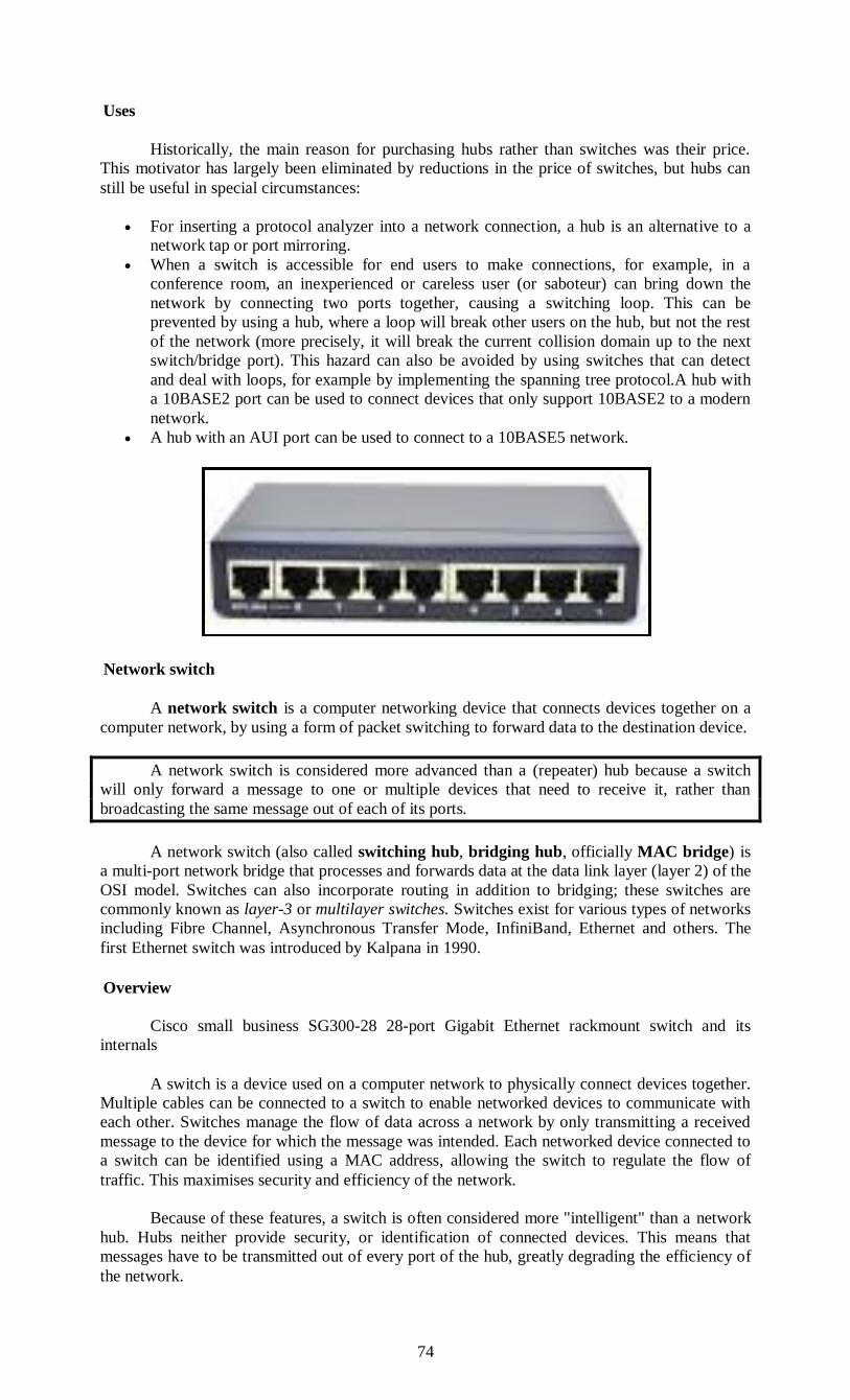
74
Uses
Historically, the main reason for purchasing hubs rather than switches was their price.
This motivator has largely been eliminated by reductions in the price of switches, but hubs can
still be useful in special circumstances:
For inserting a protocol analyzer into a network connection, a hub is an alternative to a
network tap or port mirroring.
When a switch is accessible for end users to make connections, for example, in a
conference room, an inexperienced or careless user (or saboteur) can bring down the
network by connecting two ports together, causing a switching loop. This can be
prevented by using a hub, where a loop will break other users on the hub, but not the rest
of the network (more precisely, it will break the current collision domain up to the next
switch/bridge port). This hazard can also be avoided by using switches that can detect
and deal with loops, for example by implementing the spanning tree protocol.A hub with
a 10BASE2 port can be used to connect devices that only support 10BASE2 to a modern
network.
A hub with an AUI port can be used to connect to a 10BASE5 network.
Network switch
A network switch is a computer networking device that connects devices together on a
computer network, by using a form of packet switching to forward data to the destination device.
A network switch is considered more advanced than a (repeater) hub because a switch
will only forward a message to one or multiple devices that need to receive it, rather than
broadcasting the same message out of each of its ports.
A network switch (also called switching hub, bridging hub, officially MAC bridge) is
a multi-port network bridge that processes and forwards data at the data link layer (layer 2) of the
OSI model. Switches can also incorporate routing in addition to bridging; these switches are
commonly known as layer-3 or multilayer switches. Switches exist for various types of networks
including Fibre Channel, Asynchronous Transfer Mode, InfiniBand, Ethernet and others. The
first Ethernet switch was introduced by Kalpana in 1990.
Overview
Cisco small business SG300-28 28-port Gigabit Ethernet rackmount switch and its
internals
A switch is a device used on a computer network to physically connect devices together.
Multiple cables can be connected to a switch to enable networked devices to communicate with
each other. Switches manage the flow of data across a network by only transmitting a received
message to the device for which the message was intended. Each networked device connected to
a switch can be identified using a MAC address, allowing the switch to regulate the flow of
traffic. This maximises security and efficiency of the network.
Because of these features, a switch is often considered more "intelligent" than a network
hub. Hubs neither provide security, or identification of connected devices. This means that
messages have to be transmitted out of every port of the hub, greatly degrading the efficiency of
the network.

75
Network design
An Ethernet switch operates at the data link layer of the OSI model to create a separate
collision domain for each switch port. Each computer connected to a switch port can transfer
data to any of the other ones at a time, and the transmissions will not interfere with the limitation
that, in half duplex mode, each line can only either receive from or transmit to its connected
computer at a certain time. In full duplex mode, each line can simultaneously transmit and
receive, regardless of the partner.
In the case of using a repeater hub, only a single transmission could take place at a time
for all ports combined, so they would all share the bandwidth and run in half duplex. Necessary
arbitration would also result in collisions requiring retransmissions.
Applications
The network switch plays an integral part in most modern Ethernet local area networks
(LANs). Mid-to-large sized LANs contain a number of linked managed switches. Small
office/home office (SOHO) applications typically use a single switch, or an all-purpose
converged device such as a residential gateway to access small office/home broadband services
such as DSL or cable Internet. In most of these cases, the end-user device contains a router and
components that interface to the particular physical broadband technology. User devices may
also include a telephone interface for Voice over IP (VoIP) protocol.
Microsegmentation
Segmentation is the use of a bridge or a switch (or a router) to split a larger collision
domain into smaller ones in order to reduce collision probability and improve overall throughput.
In the extreme, i. e. microsegmentation, each device is located on a dedicated switch port. In
contrast to an Ethernet hub, there is a separate collision domain on each of the switch ports. This
allows computers to have dedicated bandwidth on point-to-point connections to the network and
also to run in full-duplex without collisions. Full-duplex mode has only one transmitter and one
receiver per 'collision domain', making collisions impossible.
Role of switches in a network
Switches may operate at one or more layers of the OSI model, including the data link and
network layers. A device that operates simultaneously at more than one of these layers is known
as a multilayer switch.
In switches intended for commercial use, built-in or modular interfaces make it possible
to connect different types of networks, including Ethernet, Fibre Channel, ATM, ITU-T G.hn
and 802.11. This connectivity can be at any of the layers mentioned. While layer-2 functionality
is adequate for bandwidth-shifting within one technology, interconnecting technologies such as
Ethernet and token ring is easier at layer 3.
Devices that interconnect at layer 3 are traditionally called routers, so layer-3 switches
can also be regarded as (relatively primitive) routers.
Where there is a need for a great deal of analysis of network performance and security,
switches may be connected between WAN routers as places for analytic modules. Some vendors
provide firewall, network intrusion detection, and performance analysis modules that can plug
into switch ports. Some of these functions may be on combined modules.
In other cases, the switch is used to create a mirror image of data that can go to an external
device. Since most switch port mirroring provides only one mirrored stream, network hubs can
be useful for fanning out data to several read-only analyzers, such as intrusion detection systems
and packet sniffers.

76
Layer-specific functionality
A modular network switch with three network modules (a total of 24 Ethernet and 14
Fast Ethernet ports) and one power supply.
While switches may learn about topologies at many layers, and forward at one or more
layers, they do tend to have common features. Other than for high-performance applications,
modern commercial switches use primarily Ethernet interfaces.
At any layer, a modern switch may implement power over Ethernet (PoE), which avoids
the need for attached devices, such as a VoIP phone or wireless access point, to have a separate
power supply. Since switches can have redundant power circuits connected to uninterruptible
power supplies, the connected device can continue operating even when regular office power
fails.
Layer 1 (Hubs versus higher-layer switches)
A network hub, or repeater, is a simple network device. Repeater hubs do not manage any
of the traffic that comes through them. Any packet entering a port is flooded out or "repeated" on
every other port, except for the port of entry. Since every packet is repeated on every other port,
packet collisions affect the entire network, limiting its capacity.
A switch creates the – originally mandatory – Layer 1 end-to-end connection only
virtually. Its bridge function selects which packets are forwarded to which port(s) on the basis of
information taken from layer 2 (or higher), removing the requirement that every node be
presented with all data. The connection lines are not "switched" literally, it only appears like this
on the packet level. "Bridging hub", "switching hub", or "multiport bridge" would be more
appropriate terms.
There are specialized applications where a hub can be useful, such as copying traffic to
multiple network sensors. High end switches have a feature which does the same thing called
port mirroring.
By the early 2000s, there was little price difference between a hub and a low-end switch.
Layer 2
A network bridge, operating at the data link layer, may interconnect a small number of
devices in a home or the office. This is a trivial case of bridging, in which the bridge learns the
MAC address of each connected device.
Single bridges also can provide extremely high performance in specialized applications
such as storage area networks.
Classic bridges may also interconnect using a spanning tree protocol that disables links so
that the resulting local area network is a tree without loops. In contrast to routers, spanning tree
bridges must have topologies with only one active path between two points. The older IEEE
802.1D spanning tree protocol could be quite slow, with forwarding stopping for 30 seconds
while the spanning tree reconverged. A Rapid Spanning Tree Protocol was introduced as IEEE
802.1w. The newest standard Shortest path bridging (IEEE 802.1aq) is the next logical
progression and incorporates all the older Spanning Tree Protocols (IEEE 802.1D STP, IEEE
802.1w RSTP, IEEE 802.1s MSTP) that blocked traffic on all but one alternative path. IEEE
802.1aq (Shortest Path Bridging SPB) allows all paths to be active with multiple equal cost
paths, provides much larger layer 2 topologies (up to 16 million compared to the 4096 VLANs
limit), faster convergence, and improves the use of the mesh topologies through increase
bandwidth and redundancy between all devices by allowing traffic to load share across all paths
of a mesh network.[11][12][13][14]
While layer 2 switch remains more of a marketing term than a technical term,[citation needed]
the products that were introduced as "switches" tended to use microsegmentation and Full duplex
to prevent collisions among devices connected to Ethernet. By using an internal forwarding plane
77
much faster than any interface, they give the impression of simultaneous paths among multiple
devices. 'Non-blocking' devices use a forwarding plane or equivalent method fast enough to
allow full duplex traffic for each port simultaneously.
Once a bridge learns the addresses of its connected nodes, it forwards data link layer
frames using a layer 2 forwarding method. There are four forwarding methods a bridge can use,
of which the second through fourth method were performance-increasing methods when used on
"switch" products with the same input and output port bandwidths:
1. Store and forward: The switch buffers and verifies each frame before forwarding it.
2. Cut through: The switch reads only up to the frame's hardware address before starting to
forward it. Cut-through switches have to fall back to store and forward if the outgoing
port is busy at the time the packet arrives. There is no error checking with this method.
3. Fragment free: A method that attempts to retain the benefits of both store and forward
and cut through. Fragment free checks the first 64 bytes of the frame, where addressing
information is stored. According to Ethernet specifications, collisions should be detected
during the first 64 bytes of the frame, so frames that are in error because of a collision
will not be forwarded. This way the frame will always reach its intended destination.
Error checking of the actual data in the packet is left for the end device.
4. Adaptive switching: A method of automatically selecting between the other three modes.
While there are specialized applications, such as storage area networks, where the input
and output interfaces are the same bandwidth, this is not always the case in general LAN
applications. In LANs, a switch used for end user access typically concentrates lower bandwidth
and uplinks into a higher bandwidth.
Layer 3
Within the confines of the Ethernet physical layer, a layer-3 switch can perform some or
all of the functions normally performed by a router. The most common layer-3 capability is
awareness of IP multicast through IGMP snooping. With this awareness, a layer-3 switch can
increase efficiency by delivering the traffic of a multicast group only to ports where the attached
device has signaled that it wants to listen to that group.
Layer 4
While the exact meaning of the term layer-4 switch is vendor-dependent, it almost always
starts with a capability for network address translation, but then adds some type of load
distribution based on TCP sessions.[15]
The device may include a stateful firewall, a VPN concentrator, or be an IPSec security gateway.
Layer 7
Layer-7 switches may distribute loads based on Uniform Resource Locator URL or by
some installation-specific technique to recognize application-level transactions. A layer-7 switch
may include a web cache and participate in a content delivery network.[16]
Types of switches
Form factor
Desktop, not mounted in an enclosure, typically intended to be used in a home or office
environment outside of a wiring closet.
Rack-mounted, a switch that mounts in an equipment rack.
Chassis, with swappable module cards.
DIN rail–mounted, normally seen in industrial environments.
Configuration options
Unmanaged switches – these switches have no configuration interface or options. They
are plug and play. They are typically the least expensive switches, and therefore often

78
used in a small office/home office environment. Unmanaged switches can be desktop or
rack mounted.
Managed switches – these switches have one or more methods to modify the operation
of the switch. Common management methods include: a command-line interface (CLI)
accessed via serial console, telnet or Secure Shell, an embedded Simple Network
Management Protocol (SNMP) agent allowing management from a remote console or
management station, or a web interface for management from a web browser. Examples
of configuration changes that one can do from a managed switch include: enabling
features such as Spanning Tree Protocol or port mirroring, setting port bandwidth,
creating or modifying Virtual LANs (VLANs), etc. Two sub-classes of managed switches
are marketed today:
o Smart (or intelligent) switches – these are managed switches with a limited set
of management features. Likewise "web-managed" switches are switches which
fall into a market niche between unmanaged and managed. For a price much
lower than a fully managed switch they provide a web interface (and usually no
CLI access) and allow configuration of basic settings, such as VLANs, port-
bandwidth and duplex.[17]
o Enterprise Managed (or fully managed) switches – these have a full set of
management features, including CLI, SNMP agent, and web interface. They may
have additional features to manipulate configurations, such as the ability to
display, modify, backup and restore configurations. Compared with smart
switches, enterprise switches have more features that can be customized or
optimized, and are generally more expensive than smart switches. Enterprise
switches are typically found in networks with larger number of switches and
connections, where centralized management is a significant savings in
administrative time and effort. A stackable switch is a version of enterprise-
managed switch.
HP Procurve rack-mounted switches mounted in a standard Telco Rack 19-inch rack with
network cables
Turn particular port range on or off
Link bandwidth and duplex settings
Priority settings for ports
IP Management by IP Clustering
MAC filtering and other types of "port security" features which prevent MAC flooding
Use of Spanning Tree Protocol
SNMP monitoring of device and link health
Port mirroring (also known as: port monitoring, spanning port, SPAN port, roving
analysis port or link mode port)
Link aggregation (also known as bonding, trunking or teaming) allows the use of multiple
ports for the same connection achieving higher data transfer rates
VLAN settings. Creating VLANs can serve security and performance goals by reducing
the size of the broadcast domain
802.1X network access control
IGMP snooping
Traffic monitoring on a switched network
Unless port mirroring or other methods such as RMON, SMON or Flow are implemented
in a switch, it is difficult to monitor traffic that is bridged using a switch because only the
sending and receiving ports can see the traffic. These monitoring features are rarely present on
consumer-grade switches.
Two popular methods that are specifically designed to allow a network analyst to monitor traffic
are:
Port mirroring – the switch sends a copy of network packets to a monitoring network
connection.
SMON – "Switch Monitoring" is described by RFC 2613 and is a protocol for controlling
facilities such as port mirroring.
79
Another method to monitor may be to connect a layer-1 hub between the monitored device and
its switch port. This will induce minor delay, but will provide multiple interfaces that can be used
to monitor the individual switch port.
Router (computing)
A router is a networking device, commonly specialized hardware, that forwards data
packets between computer networks. This creates an overlay internetwork, as a router is
connected to two or more data lines from different networks. When a data packet comes in one
of the lines, the router reads the address information in the packet to determine its ultimate
destination. Then, using information in its routing table or routing policy, it directs the packet to
the next network on its journey. Routers perform the "traffic directing" functions on the Internet.
A data packet is typically forwarded from one router to another through the networks that
constitute the internetwork until it reaches its destination node.
The most familiar type of routers are home and small office routers that simply pass data,
such as web pages, email, IM, and videos between the home computers and the Internet. An
example of a router would be the owner's cable or DSL router, which connects to the Internet
through an ISP. More sophisticated routers, such as enterprise routers, connect large business or
ISP networks up to the powerful core routers that forward data at high speed along the optical
fiber lines of the Internet backbone. Though routers are typically dedicated hardware devices,
use of software-based routers has grown increasingly common.
Applications
When multiple routers are used in interconnected networks, the routers exchange
information about destination addresses using a dynamic routing protocol. Each router builds up
a table listing the preferred routes between any two systems on the interconnected networks. A
router has interfaces for different physical types of network connections, such as copper cables,
fiber optic, or wireless transmission. It also contains firmware for different networking
communications protocol standards. Each network interface uses this specialized computer
software to enable data packets to be forwarded from one protocol transmission system to
another.
Routers may also be used to connect two or more logical groups of computer devices
known as subnets, each with a different sub-network address.
The subnet addresses recorded in the router do not necessarily map directly to the
physical interface connections.
A router has two stages of operation called planes:
Control plane: A router maintains a routing table that lists which route should be used to
forward a data packet, and through which physical interface connection. It does this using
internal pre-configured directives, called static routes, or by learning routes using a
dynamic routing protocol. Static and dynamic routes are stored in the Routing
Information Base (RIB). The control-plane logic then strips the RIB from non essential
directives and builds a Forwarding Information Base (FIB) to be used by the forwarding-
plane.
Forwarding plane: The router forwards data packets between incoming and outgoing
interface connections. It routes them to the correct network type using information that
the packet header contains. It uses data recorded in the routing table control plane.
Routers may provide connectivity within enterprises, between enterprises and the
Internet, or between internet service providers' (ISPs) networks. The largest routers (such as the
Cisco CRS-1 or Juniper T1600) interconnect the various ISPs, or may be used in large enterprise
networks. Smaller routers usually provide connectivity for typical home and office networks.
Other networking solutions may be provided by a backbone Wireless Distribution System
(WDS), which avoids the costs of introducing networking cables into buildings.
80
All sizes of routers may be found inside enterprises. The most powerful routers are
usually found in ISPs, academic and research facilities. Large businesses may also need more
powerful routers to cope with ever increasing demands of intranet data traffic. A three-layer
model is in common use, not all of which need be present in smaller networks.
Access
A screenshot of the LuCI web interface used by OpenWrt. This page configures Dynamic
DNS.
Access routers, including 'small office/home office' (SOHO) models, are located at
customer sites such as branch offices that do not need hierarchical routing of their own.
Typically, they are optimized for low cost. Some SOHO routers are capable of running
alternative free Linux-based firmwares like Tomato, OpenWrt or DD-WRT.
Distribution
Distribution routers aggregate traffic from multiple access routers, either at the same site,
or to collect the data streams from multiple sites to a major enterprise location. Distribution
routers are often responsible for enforcing quality of service across a WAN, so they may have
considerable memory installed, multiple WAN interface connections, and substantial onboard
data processing routines. They may also provide connectivity to groups of file servers or other
external networks.
Security
External networks must be carefully considered as part of the overall security strategy. A
router may include a firewall, VPN handling, and other security functions, or these may be
handled by separate devices. Many companies produced security-oriented routers, including
Cisco Systems' PIX and ASA5500 series, Juniper's Netscreen, Watchguard's Firebox,
Barracuda's variety of mail-oriented devices, and many others. Routers also commonly perform
network address translation, which allows multiple devices on a network to share a single public
IP address.
Core
In enterprises, a core router may provide a "collapsed backbone" interconnecting the
distribution tier routers from multiple buildings of a campus, or large enterprise locations. They
tend to be optimized for high bandwidth, but lack some of the features of Edge Routers.
Internet connectivity and internal use
Routers intended for ISP and major enterprise connectivity usually exchange routing
information using the Border Gateway Protocol (BGP). RFC 4098 standard defines the types of
BGP routers according to their functions:
Edge router: Also called a Provider Edge router, is placed at the edge of an ISP network.
The router uses External BGP to EBGP routers in other ISPs, or a large enterprise
Autonomous System.
Subscriber edge router: Also called a Customer Edge router, is located at the edge of the
subscriber's network, it also uses EBGP to its provider's Autonomous System. It is
typically used in an (enterprise) organization.
Inter-provider border router: Interconnecting ISPs, is a BGP router that maintains BGP
sessions with other BGP routers in ISP Autonomous Systems.
Core router: A core router resides within an Autonomous System as a back bone to carry
traffic between edge routers.
Within an ISP: In the ISP's Autonomous System, a router uses internal BGP to
communicate with other ISP edge routers, other intranet core routers, or the ISP's intranet
provider border routers.
"Internet backbone:" The Internet no longer has a clearly identifiable backbone, unlike its
predecessor networks. See default-free zone (DFZ). The major ISPs' system routers make

81
up what could be considered to be the current Internet backbone core.ISPs operate all
four types of the BGP routers described here. An ISP "core" router is used to interconnect
its edge and border routers. Core routers may also have specialized functions in virtual
private networks based on a combination of BGP and Multi-Protocol Label Switching
protocols.
Port forwarding: Routers are also used for port forwarding between private Internet
connected servers.
Voice/Data/Fax/Video Processing Routers: Commonly referred to as access servers or
gateways, these devices are used to route and process voice, data, video and fax traffic on
the Internet. Since 2005, most long-distance phone calls have been processed as IP traffic
(VOIP) through a voice gateway. Voice traffic that the traditional cable networks once
carried. Use of access server type routers expanded with the advent of the Internet, first
with dial-up access and another resurgence with voice phone service.
Historical and technical information
The very first device that had fundamentally the same functionality as a router does
today, was the Interface Message Processor (IMP); IMPs were the devices that made up the
ARPANET, the first packet network. The idea for a router (called "gateways" at the time)
initially came about through an international group of computer networking researchers called
the International Network Working Group (INWG). Set up in 1972 as an informal group to
consider the technical issues involved in connecting different networks, later that year it became
a subcommittee of the International Federation for Information Processing.[16]
These devices were different from most previous packet networks in two ways. First,
they connected dissimilar kinds of networks, such as serial lines and local area networks.
Second, they were connectionless devices, which had no role in assuring that traffic was
delivered reliably, leaving that entirely to the hosts (this particular idea had been previously
pioneered in the CYCLADES network).
The idea was explored in more detail, with the intention to produce a prototype system,
as part of two contemporaneous programs. One was the initial DARPA-initiated program, which
created the TCP/IP architecture in use today.[17] The other was a program at Xerox PARC to
explore new networking technologies, which produced the PARC Universal Packet system; due
to corporate intellectual property concerns it received little attention outside Xerox for years.[18]
Some time after early 1974 the first Xerox routers became operational. The first true IP
router was developed by Virginia Strazisar at BBN, as part of that DARPA-initiated effort,
during 1975-1976. By the end of 1976, three PDP-11-based routers were in service in the
experimental prototype Internet.[19]
The first multiprotocol routers were independently created by staff researchers at MIT
and Stanford in 1981; the Stanford router was done by William Yeager, and the MIT one by
Noel Chiappa; both were also based on PDP-11s.[20][21][22][23]
Virtually all networking now uses TCP/IP, but multiprotocol routers are still
manufactured. They were important in the early stages of the growth of computer networking,
when protocols other than TCP/IP were in use. Modern Internet routers that handle both IPv4
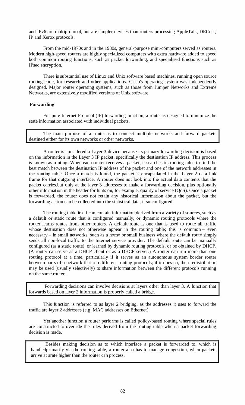
82
and IPv6 are multiprotocol, but are simpler devices than routers processing AppleTalk, DECnet,
IP and Xerox protocols.
From the mid-1970s and in the 1980s, general-purpose mini-computers served as routers.
Modern high-speed routers are highly specialized computers with extra hardware added to speed
both common routing functions, such as packet forwarding, and specialised functions such as
IPsec encryption.
There is substantial use of Linux and Unix software based machines, running open source
routing code, for research and other applications. Cisco's operating system was independently
designed. Major router operating systems, such as those from Juniper Networks and Extreme
Networks, are extensively modified versions of Unix software.
Forwarding
For pure Internet Protocol (IP) forwarding function, a router is designed to minimize the
state information associated with individual packets.
The main purpose of a router is to connect multiple networks and forward packets
destined either for its own networks or other networks.
A router is considered a Layer 3 device because its primary forwarding decision is based
on the information in the Layer 3 IP packet, specifically the destination IP address. This process
is known as routing. When each router receives a packet, it searches its routing table to find the
best match between the destination IP address of the packet and one of the network addresses in
the routing table. Once a match is found, the packet is encapsulated in the Layer 2 data link
frame for that outgoing interface. A router does not look into the actual data contents that the
packet carries.but only at the layer 3 addresses to make a forwarding decision, plus optionally
other information in the header for hints on, for example, quality of service (QoS). Once a packet
is forwarded, the router does not retain any historical information about the packet, but the
forwarding action can be collected into the statistical data, if so configured.
The routing table itself can contain information derived from a variety of sources, such as
a default or static route that is configured manually, or dynamic routing protocols where the
router learns routes from other routers. A default route is one that is used to route all traffic
whose destination does not otherwise appear in the routing table; this is common – even
necessary – in small networks, such as a home or small business where the default route simply
sends all non-local traffic to the Internet service provider. The default route can be manually
configured (as a static route), or learned by dynamic routing protocols, or be obtained by DHCP.
(A router can serve as a DHCP client or as a DHCP server.) A router can run more than one
routing protocol at a time, particularly if it serves as an autonomous system border router
between parts of a network that run different routing protocols; if it does so, then redistribution
may be used (usually selectively) to share information between the different protocols running
on the same router.
Forwarding decisions can involve decisions at layers other than layer 3. A function that
forwards based on layer 2 information is properly called a bridge.
This function is referred to as layer 2 bridging, as the addresses it uses to forward the
traffic are layer 2 addresses (e.g. MAC addresses on Ethernet).
Yet another function a router performs is called policy-based routing where special rules
are constructed to override the rules derived from the routing table when a packet forwarding
decision is made.
Besides making decision as to which interface a packet is forwarded to, which is
handledprimarily via the routing table, a router also has to manage congestion, when packets
arrive at arate higher than the router can process.

83
Three policies commonly used in the Internet are tail drop, random early detection
(RED), and weighted random early detection (WRED). Tail drop is the simplest and most easily
implemented; the router simply drops packets once the length of the queue exceeds the size of
the buffers in the router. RED probabilistically drops datagrams early when the queue exceeds a
pre-configured portion of the buffer, until a pre-determined max, when it becomes tail drop.
WRED requires a weight on the average queue size to act upon when the traffic is about to
exceed the pre-configured size, so that short bursts will not trigger random drops.
Another function a router performs is to decide which packet should be processed first
when multiple queues exist. This is managed through QoS, which is critical when Voice over IP
is deployed, so that delays between packets do not exceed 150ms to maintain the quality of voice
conversations.
These functions may be performed through the same internal paths that the packets travel
inside the router. Some of the functions may be performed through an application-specific
integrated circuit (ASIC) to avoid overhead caused by multiple CPU cycles, and others may have
to be performed through the CPU as these packets need special attention that cannot be handled
by an ASIC.
Wireless access point
In computer networking, a wireless Access Point (AP) is a device that allows wireless
devices to connect to a wired network using Wi-Fi, or related standards. The AP usually
connects to a router (via a wired network) as a standalone device, but it can also be an integral
component of the router itself.
Introduction
Access Points connecting university campus; APs are controlled by a single, common
WLAN Controller
Embedded RouterBoard 112 with U.FL-RSMA pigtail and R52 mini PCI Wi-Fi card
widely used by wireless Internet service providers (WISPs) across the world
Prior to wireless networks, setting up a computer network in a business, home or school
often required running many cables through walls and ceilings in order to deliver network access
to all of the network-enabled devices in the building.
With the creation of the wireless Access Point (AP), network users are now able to add
devices that access the network with few or no cables. An AP normally connects directly to a
wired Ethernet connection and the AP then provides wireless connections using radio frequency
links for other devices to utilize that wired connection. Most APs support the connection of
multiple wireless devices to one wired connection. Modern APs are built to support a standard
for sending and receiving data using, these radio frequencies. Those standards, and the
frequencies they use are defined by the IEEE. Most APs use IEEE 802.11 standards.
Common AP applications
Typical corporate use involves attaching several APs to a wired network and then
providing wireless access to the office LAN. The wireless access points are managed by a
WLAN Controller which handles automatic adjustments to RF power, channels, authentication,
and security. Furthermore, controllers can be combined to form a wireless mobility group to
allow inter-controller roaming. The controllers can be part of a mobility domain to allow clients
access throughout large or regional office locations. This saves the clients time and
administrators overhead because it can automatically re-associate or re-authenticate.
A hotspot is a common public application of APs, where wireless clients can connect to
the Internet without regard for the particular networks to which they have attached for the
moment.
84
The concept has become common in large cities, where a combination of coffeehouses,
libraries, as well as privately owned open access points, allow clients to stay more or less
continuously connected to the Internet, while moving around. A collection of connected hotspots
can be referred to as a lily pad network.
APs are commonly used in home wireless networks. Home networks generally have only
one AP to connect all the computers in a home. Most are wireless routers, meaning converged
devices that include the AP, a router, and, often, an Ethernet switch. Many also include a
broadband modem. In places where most homes have their own AP within range of the
neighbours' AP, it's possible for technically savvy people to turn off their encryption and set up a
wireless community network, creating an intra-city communication network although this does
not negate the requirement for a wired network.
An AP may also act as the network's arbitrator, negotiating when each nearby client
device can transmit. However, the vast majority of currently installed IEEE 802.11 networks do
not implement this, using a distributed pseudo-random algorithm called CSMA/CA instead.
Wireless access point vs. ad hoc network
Some people confuse wireless access points with wireless ad hoc networks. An ad hoc
network uses a connection between two or more devices without using a wireless access point:
the devices communicate directly when in range. An ad hoc network is used in situations such as
a quick data exchange or a multiplayer LAN game because setup is easy and does not require an
access point. Due to its peer-to-peer layout, ad hoc connections are similar to Bluetooth ones and
are generally not recommended for a permanent installation.[citation needed]
Internet access via ad hoc networks, using features like Windows' Internet Connection
Sharing, may work well with a small number of devices that are close to each other, but ad hoc
networks don't scale well. Internet traffic will converge to the nodes with direct internet
connection, potentially congesting these nodes. For internet-enabled nodes, access points have a
clear advantage, with the possibility of having multiple access points connected by a wired LAN.
Limitations
One IEEE 802.11 AP can typically communicate with 30 client systems located within a
radius of 103 m.However, the actual range of communication can vary significantly, depending
on such variables as indoor or outdoor placement, height above ground, nearby obstructions,
other electronic devices that might actively interfere with the signal by broadcasting on the same
frequency, type of antenna, the current weather, operating radio frequency, and the power output
of devices. Network designers can extend the range of APs through the use of repeaters and
reflectors, which can bounce or amplify radio signals that ordinarily would go un-received. In
experimental conditions, wireless networking has operated over distances of several hundred
kilometers.
Most jurisdictions have only a limited number of frequencies legally available for use by
wireless networks. Usually, adjacent WAPs will use different frequencies (Channels) to
communicate with their clients in order to avoid interference between the two nearby systems.
Wireless devices can "listen" for data traffic on other frequencies, and can rapidly switch from
one frequency to another to achieve better reception. However, the limited number of
frequencies becomes problematic in crowded downtown areas with tall buildings using multiple
WAPs. In such an environment, signal overlap becomes an issue causing interference, which
results in signal droppage and data errors.
Wireless networking lags wired networking in terms of increasing bandwidth and
throughput. While (as of 2013) high-density 256-QAM (TurboQAM) modulation, 3-antenna
wireless devices for the consumer market can reach sustained real-world speeds of some 240
Mbit/s at 13 m behind two standing walls (NLOS) depending on their nature &c or 360 Mbit/s at
10 m line of sight or 380 Mbit/s at 2 m line of sight (IEEE 802.11ac) or 20 to 25 Mbit/s at 2 m
line of sight (IEEE 802.11g), wired hardware of similar cost reaches somewhat less than 1000
Mbit/s up to specified distance of 100 m with twisted-pair cabling (Cat-5, Cat-5e, Cat-6, or
Cat-7) (Gigabit Ethernet). One impediment to increasing the speed of wireless communications
comes from Wi-Fi's use of a shared communications medium: Thus, two stations in
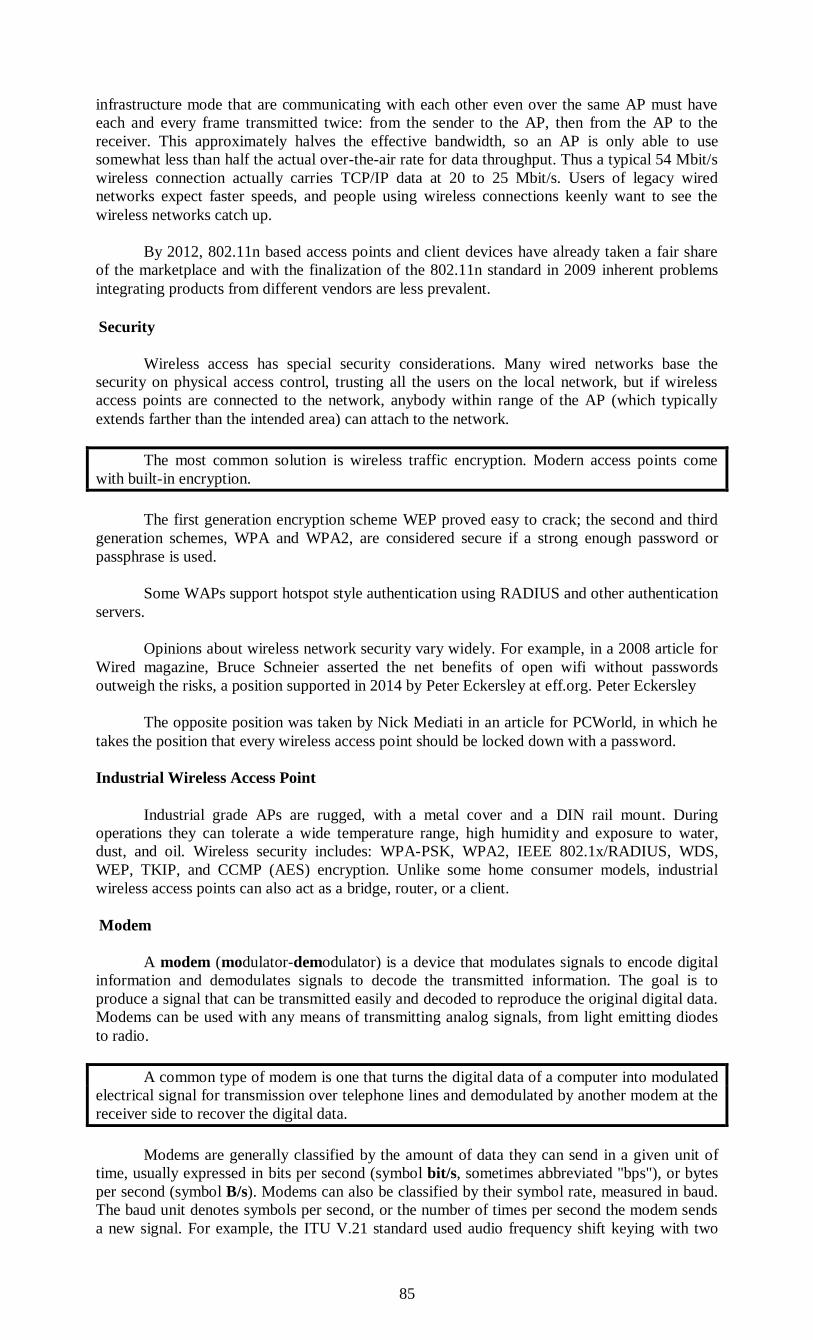
85
infrastructure mode that are communicating with each other even over the same AP must have
each and every frame transmitted twice: from the sender to the AP, then from the AP to the
receiver. This approximately halves the effective bandwidth, so an AP is only able to use
somewhat less than half the actual over-the-air rate for data throughput. Thus a typical 54 Mbit/s
wireless connection actually carries TCP/IP data at 20 to 25 Mbit/s. Users of legacy wired
networks expect faster speeds, and people using wireless connections keenly want to see the
wireless networks catch up.
By 2012, 802.11n based access points and client devices have already taken a fair share
of the marketplace and with the finalization of the 802.11n standard in 2009 inherent problems
integrating products from different vendors are less prevalent.
Security
Wireless access has special security considerations. Many wired networks base the
security on physical access control, trusting all the users on the local network, but if wireless
access points are connected to the network, anybody within range of the AP (which typically
extends farther than the intended area) can attach to the network.
The most common solution is wireless traffic encryption. Modern access points come
with built-in encryption.
The first generation encryption scheme WEP proved easy to crack; the second and third
generation schemes, WPA and WPA2, are considered secure if a strong enough password or
passphrase is used.
Some WAPs support hotspot style authentication using RADIUS and other authentication
servers.
Opinions about wireless network security vary widely. For example, in a 2008 article for
Wired magazine, Bruce Schneier asserted the net benefits of open wifi without passwords
outweigh the risks, a position supported in 2014 by Peter Eckersley at eff.org. Peter Eckersley
The opposite position was taken by Nick Mediati in an article for PCWorld, in which he
takes the position that every wireless access point should be locked down with a password.
Industrial Wireless Access Point
Industrial grade APs are rugged, with a metal cover and a DIN rail mount. During
operations they can tolerate a wide temperature range, high humidity and exposure to water,
dust, and oil. Wireless security includes: WPA-PSK, WPA2, IEEE 802.1x/RADIUS, WDS,
WEP, TKIP, and CCMP (AES) encryption. Unlike some home consumer models, industrial
wireless access points can also act as a bridge, router, or a client.
Modem
A modem (modulator-demodulator) is a device that modulates signals to encode digital
information and demodulates signals to decode the transmitted information. The goal is to
produce a signal that can be transmitted easily and decoded to reproduce the original digital data.
Modems can be used with any means of transmitting analog signals, from light emitting diodes
to radio.
A common type of modem is one that turns the digital data of a computer into modulated
electrical signal for transmission over telephone lines and demodulated by another modem at the
receiver side to recover the digital data.
Modems are generally classified by the amount of data they can send in a given unit of
time, usually expressed in bits per second (symbol bit/s, sometimes abbreviated "bps"), or bytes
per second (symbol B/s). Modems can also be classified by their symbol rate, measured in baud.
The baud unit denotes symbols per second, or the number of times per second the modem sends
a new signal. For example, the ITU V.21 standard used audio frequency shift keying with two

86
possible frequencies, corresponding to two distinct symbols (or one bit per symbol), to carry 300
bits per second using 300 baud. By contrast, the original ITU V.22 standard, which could
transmit and receive four distinct symbols (two bits per symbol), transmitted 1,200 bits by
sending 600 symbols per second (600 baud) using phase shift keying.
Dialup modem
News wire services in the 1920s used multiplex devices that satisfied the definition of a
modem. However the modem function was incidental to the multiplexing function, so they are
not commonly included in the history of modems. Modems grew out of the need to connect
teleprinters over ordinary phone lines instead of the more expensive leased lines which had
previously been used for current loop–based teleprinters and automated telegraphs. In 1942, IBM
adapted this technology to their unit record equipment and were able to transmit punched cards
at 25 bits/second.
Mass-produced modems in the United States began as part of the SAGE air-defense
system in 1958 (the year the word modem was first used[1]), connecting terminals at various
airbases, radar sites, and command-and-control centers to the SAGE director centers scattered
around the U.S. and Canada. SAGE modems were described by AT&T's Bell Labs as
conforming to their newly published Bell 101 dataset standard. While they ran on dedicated
telephone lines, the devices at each end were no different from commercial acoustically coupled
Bell 101, 110 baud modems.
In summer 1960, the name Data-Phone was introduced to replace the earlier term digital
subset. The 202 Data-Phone was a half-duplex asynchronous service that was marketed
extensively in late 1960. In 1962, the 201A and 201B Data-Phones were introduced. They were
synchronous modems using two-bit-per-baud phase-shift keying (PSK). The 201A operated half-
duplex at 2,000 bit/s over normal phone lines, while the 201B provided full duplex 2,400 bit/s
service on four-wire leased lines, the send and receive channels each running on their own set of
two wires.
The famous Bell 103A dataset standard was also introduced by AT&T in 1962. It
provided full-duplex service at 300 bit/s over normal phone lines. Frequency-shift keying was
used, with the call originator transmitting at 1,070 or 1,270 Hz and the answering modem
transmitting at 2,025 or 2,225 Hz. The readily available 103A2 gave an important boost to the
use of remote low-speed terminals such as the Teletype Model 33 ASR and KSR, and the IBM
2741. AT&T reduced modem costs by introducing the originate-only 113D and the answer-only
113B/C modems.
For many years, the Bell System (AT&T) maintained a monopoly on the use of its phone
lines, and what devices could be connected to its lines. However, the seminal Hush-a-Phone v.
FCC case of 1956 concluded that it was within the FCC's jurisdiction to regulate the operation of
the System. Subsequently, the FCC examiner found that as long as the device was not
electrically attached it would not threaten to degenerate the system. This led to a number of
devices that mechanically connected to the phone, through a standard handset. Since most
handsets were supplied from Western Electric, it was relatively easy to build such an acoustic
coupler, and this style of connection was used for many devices like answering machines.
Acoustically coupled Bell 103A-compatible 300 bit/s modems became common during
the 1970s, with well-known models including the Novation CAT and the Anderson-Jacobson,
the latter spun off from an in-house project at Stanford Research Institute (now SRI
International). An even lower-cost option was the Pennywhistle modem, designed to be built
using parts found at electronics scrap and surplus stores.
In December 1972, Vadic introduced the VA3400, which was notable because it provided
full duplex operation at 1,200 bit/s over the phone network. Like the 103A, it used different
frequency bands for transmit and receive. In November 1976, AT&T introduced the 212A
modem to compete with Vadic. It was similar in design to Vadic's model, but used the lower
frequency set for transmission. One could also use the 212A with a 103A modem at 300 bit/s.
According to Vadic, the change in frequency assignments made the 212 intentionally
incompatible with acoustic coupling, thereby locking out many potential modem manufacturers.
In 1977, Vadic responded with the VA3467 triple modem, an answer-only modem sold to

87
computer center operators that supported Vadic's 1,200-bit/s mode, AT&T's 212A mode, and
103A operation.
Carterfone and direct connection
The Hush-a-Phone decision applied only to mechanical collections, but the Carterfone
decision of 1968 led to the FCC introducing a rule setting stringent AT&T-designed tests for
electronically coupling a device to the phone lines. AT&T's tests were complex, making
electronically coupled modems expensive,[citation needed] so acoustically coupled modems remained
common into the early 1980s.
However, the rapidly falling prices of electronics in the late 1970s led to an increasing
number of direct-connect models around 1980. In spite of being directly connected, these
modems were generally operated like their earlier acoustic versions—dialling and other phone-
control operations were completed by hand, using an attached handset. A small number of
modems added the ability to automatically answer incoming calls, or automatically place an
outgoing call to a single number, but even these limited features were relatively rare or limited to
special models in a lineup. When more flexible solutions were needed, 3rd party "diallers" were
used to automate calling, normally using a separate serial port.
The Smartmodem and the rise of BBSs
The next major advance in modems was the Hayes Smartmodem, introduced in 1981. The
Smartmodem was an otherwise standard 103A 300-bit/s modem, but it was attached to a small
microcontroller that let the computer send it commands. The command set included instructions
for picking up and hanging up the phone, dialing numbers, and answering calls. This eliminated
the need for any manual operation, a handset, or a dialler. Terminal programs that maintained
lists of phone numbers and sent the dialing commands became common. The basic Hayes
command set remains the basis for computer control of most modern modems.
The Smartmodem and its clones also aided the spread of bulletin board systems (BBSs)
because it was the first low-cost modem that could answer calls. Modems had previously been
typically either the call-only, acoustically coupled models used on the client side, or the much
more expensive, answer-only models used on the server side. These were fine for large computer
installations, but useless for the hobbyist who wanted to run a BBS using the same telephone line
to call other systems. The first hobby BBS system, CBBS, started as an experiment in ways to
better use the Smartmodem.
Almost all modern modems can inter-operate with fax machines. Digital faxes,
introduced in the 1980s, are simply an image format sent over a high-speed (commonly
14.4 kbit/s) modem. Software running on the host computer can convert any image into fax
format, which can then be sent using the modem. Such software was at one time an add-on, but
has since become largely universal.
1200 and 2400 bit/s
The 300 bit/s modems used audio frequency-shift keying to send data. In this system the
stream of 1s and 0s in computer data is translated into sounds which can be easily sent on the
phone lines. In the Bell 103 system, the originating modem sends 0s by playing a 1,070 Hz tone,
and 1s at 1,270 Hz, with the answering modem transmitting its 0s on 2,025 Hz and 1s on
2,225 Hz. These frequencies were chosen carefully; they are in the range that suffers minimum
distortion on the phone system and are not harmonics of each other.
In the 1,200 bit/s and faster systems, phase-shift keying was used. In this system the two
tones for any one side of the connection are sent at similar frequencies as in the 300 bit/s
systems, but slightly out of phase. Voiceband modems generally remained at 300 and 1,200 bit/s
(V.21 and V.22) into the mid-1980s. A V.22bis 2,400-bit/s system similar in concept to the
1,200-bit/s Bell 212 signaling was introduced in the U.S., and a slightly different one in Europe.
The limited available frequency range meant the symbol rate of 1,200 bit/s modems was still
only 600 baud (symbols per second). The bit rate increases were achieved by defining 4 or 8
distinct symbols, which allowed the encoding of 2 or 3 bits per symbol instead of only 1. The use
of smaller shifts had the drawback of making each symbol more vulnerable to interference, but

88
improvements in phone line quality at the same time helped compensate for this. By the late
1980s, most modems could support all of these standards and 2,400-bit/s operation was
becoming common.
Proprietary standards
Many other standards were also introduced for special purposes, commonly using a high-
speed channel for receiving, and a lower-speed channel for sending. One typical example was
used in the French Minitel system, in which the user's terminals spent the majority of their time
receiving information. The modem in the Minitel terminal thus operated at 1,200 bit/s for
reception, and 75 bit/s for sending commands back to the servers.
Three U.S. companies became famous for high-speed versions of the same concept.
Telebit introduced its Trailblazer modem in 1984, which used a large number of 36 bit/s
channels to send data one-way at rates up to 18,432 bit/s. A single additional channel in the
reverse direction allowed the two modems to communicate how much data was waiting at either
end of the link, and the modems could change direction on the fly. The Trailblazer modems also
supported a feature that allowed them to spoof the UUCP g protocol, commonly used on Unix
systems to send e-mail, and thereby speed UUCP up by a tremendous amount. Trailblazers thus
became extremely common on Unix systems, and maintained their dominance in this market
well into the 1990s.
USRobotics (USR) introduced a similar system, known as HST, although this supplied
only 9,600 bit/s (in early versions at least) and provided for a larger backchannel. Rather than
offer spoofing, USR instead created a large market among Fidonet users by offering its modems
to BBS sysops at a much lower price, resulting in sales to end users who wanted faster file
transfers. Hayes was forced to compete, and introduced its own 9,600-bit/s standard, Express 96
(also known as Ping-Pong), which was generally similar to Telebit's PEP. Hayes, however,
offered neither protocol spoofing nor sysop discounts, and its high-speed modems remained rare.
Echo cancellation, 9600 and 14,400
Echo cancellation was the next major advance in modem design.
Local telephone lines use the same wires to send and receive, which results in a small
amount of the outgoing signal being reflected back. This is useful for people talking on the
phone, as it provides a signal to the speaker that their voice is making it through the system.
However, this reflected signal causes problems for the modem, which is unable to distinguish
between a signal from the remote modem and the echo of its own signal. This was why earlier
modems split the signal frequencies into "answer" and "originate"; the modem could then ignore
any signals in the frequency range it was using for transmission. Even with improvements to the
phone system allowing higher speeds, this splitting of available phone signal bandwidth still
imposed a half-speed limit on modems.
Echo cancellation eliminated this problem. Measuring the echo delays and magnitudes
allowed the modem to tell if the received signal was from itself or the remote modem, and create
an equal and opposite signal to cancel its own. Modems were then able to send over the whole
frequency spectrum in both directions at the same time, leading to the development of 4,800 and
9,600 bit/s modems.
Increases in speed have used increasingly complicated communications theory. 1,200 and
2,400 bit/s modems used the phase shift key (PSK) concept. This could transmit two or three bits
per symbol.
The next major advance encoded four bits into a combination of amplitude and phase,
known as Quadrature Amplitude Modulation (QAM).
The new V.27ter and V.32 standards were able to transmit 4 bits per symbol, at a rate of
1,200 or 2,400 baud, giving an effective bit rate of 4,800 or 9,600 bit/s. The carrier frequency
was 1,650 Hz. For many years, most engineers considered this rate to be the limit of data
communications over telephone networks.
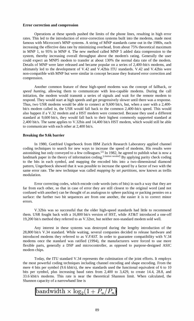
89
Error correction and compression
Operations at these speeds pushed the limits of the phone lines, resulting in high error
rates. This led to the introduction of error-correction systems built into the modems, made most
famous with Microcom's MNP systems. A string of MNP standards came out in the 1980s, each
increasing the effective data rate by minimizing overhead, from about 75% theoretical maximum
in MNP 1, to 95% in MNP 4. The new method called MNP 5 added data compression to the
system, thereby increasing overall throughput above the modem's rating. Generally the user
could expect an MNP5 modem to transfer at about 130% the normal data rate of the modem.
Details of MNP were later released and became popular on a series of 2,400-bit/s modems, and
ultimately led to the development of V.42 and V.42bis ITU standards. V.42 and V.42bis were
non-compatible with MNP but were similar in concept because they featured error correction and
compression.
Another common feature of these high-speed modems was the concept of fallback, or
speed hunting, allowing them to communicate with less-capable modems. During the call
initiation, the modem would transmit a series of signals and wait for the remote modem to
respond. They would start at high speeds and get progressively slower until there was a response.
Thus, two USR modems would be able to connect at 9,600 bit/s, but, when a user with a 2,400-
bit/s modem called in, the USR would fall back to the common 2,400-bit/s speed. This would
also happen if a V.32 modem and a HST modem were connected. Because they used a different
standard at 9,600 bit/s, they would fall back to their highest commonly supported standard at
2,400 bit/s. The same applies to V.32bis and 14,400 bit/s HST modem, which would still be able
to communicate with each other at 2,400 bit/s.
Breaking the 9.6k barrier
In 1980, Gottfried Ungerboeck from IBM Zurich Research Laboratory applied channel
coding techniques to search for new ways to increase the speed of modems. His results were
astonishing but only conveyed to a few colleagues.[2] In 1982, he agreed to publish what is now a
landmark paper in the theory of information coding.[citation needed] By applying parity check coding
to the bits in each symbol, and mapping the encoded bits into a two-dimensional diamond
pattern, Ungerboeck showed that it was possible to increase the speed by a factor of two with the
same error rate. The new technique was called mapping by set partitions, now known as trellis
modulation.
Error correcting codes, which encode code words (sets of bits) in such a way that they are
far from each other, so that in case of error they are still closest to the original word (and not
confused with another) can be thought of as analogous to sphere packing or packing pennies on a
surface: the further two bit sequences are from one another, the easier it is to correct minor
errors.
V.32bis was so successful that the older high-speed standards had little to recommend
them. USR fought back with a 16,800 bit/s version of HST, while AT&T introduced a one-off
19,200 bit/s method they referred to as V.32ter, but neither non-standard modem sold well.
Any interest in these systems was destroyed during the lengthy introduction of the
28,800 bit/s V.34 standard. While waiting, several companies decided to release hardware and
introduced modems they referred to as V.FAST. In order to guarantee compatibility with V.34
modems once the standard was ratified (1994), the manufacturers were forced to use more
flexible parts, generally a DSP and microcontroller, as opposed to purpose-designed ASIC
modem chips.
Today, the ITU standard V.34 represents the culmination of the joint efforts. It employs
the most powerful coding techniques including channel encoding and shape encoding. From the
mere 4 bits per symbol (9.6 kbit/s), the new standards used the functional equivalent of 6 to 10
bits per symbol, plus increasing baud rates from 2,400 to 3,429, to create 14.4, 28.8, and
33.6 kbit/s modems. This rate is near the theoretical Shannon limit. When calculated, the
Shannon capacity of a narrowband line is

90
with the (linear) signal-to-noise ratio. Narrowband phone lines have a bandwidth
of 3000 Hz so using (SNR = 30 dB), the capacity is approximately 30 kbit/s.
Without the discovery and eventual application of trellis modulation, maximum
telephone rates using voice-bandwidth channels would have been limited to 3,429 baud ×
4 bit/symbol = approximately 14 kbit/s using traditional QAM.
V.61/V.70 Analog/Digital Simultaneous Voice and Data
The V.61 Standard introduced Analog Simultaneous Voice and Data (ASVD). This
technology allowed users of v.61 modems to engage in point-to-point voice conversations with
each other while their respective modems communicated.
In 1995, the first DSVD (Digital Simultaneous Voice and Data) modems became
available to consumers, and the standard was ratified as v.70 by the International
Telecommunication Union (ITU) in 1996.
Two DSVD modems can establish a completely digital link between each other over
standard phone lines. Sometimes referred to as "the poor man's ISDN", and employing a similar
technology, v.70 compatible modems allow for a maximum speed of 33.6 kbit/s between peers.
By using a majority of the bandwidth for data and reserving part for voice transmission, DSVD
modems allow users to pick up a telephone handset interfaced with the modem, and initiate a call
to the other peer.
One practical use for this technology was realized by early two-player video gamers, who
could hold voice communication with each other over the phone while playing.
Using digital lines and PCM (V.90/92)
In the late 1990s Rockwell/Lucent and USRobotics introduced new competing
technologies based upon the digital transmission used in modern telephony networks. The
standard digital transmission in modern networks is 64 kbit/s but some networks use a part of the
bandwidth for remote office signaling (e.g. to hang up the phone), limiting the effective rate to
56 kbit/s DS0. This new technology was adopted into ITU standards V.90 and is common in
modern computers. The 56 kbit/s rate is only possible from the central office to the user site
(downlink). In the United States, government regulation limits the maximum power output,
resulting in a maximum data rate of 53.3 kbit/s. The uplink (from the user to the central office)
still uses V.34 technology at 33.6 kbit/s.
Later in V.92, the digital PCM technique was applied to increase the upload speed to a
maximum of 48 kbit/s, but at the expense of download rates. A 48 kbit/s upstream rate would
reduce the downstream as low as 40 kbit/s due to echo on the telephone line. To avoid this
problem, V.92 modems offer the option to turn off the digital upstream and instead use a
33.6 kbit/s analog connection, in order to maintain a high digital downstream of 50 kbit/s or
higher.[4] V.92 also adds two other features. The first is the ability for users who have call
waiting to put their dial-up Internet connection on hold for extended periods[vague] of time while
they answer a call. The second feature is the ability to quickly connect to one's ISP. This is
achieved by remembering the analog and digital characteristics of the telephone line, and using
this saved information when reconnecting.
Using compression to exceed 56k
Today's V.42, V.42bis and V.44 standards allow the modem to transmit data faster than
its basic rate would imply. For instance, a 53.3 kbit/s connection with V.44 can transmit up to
53.3*6 == 320 kbit/s using pure text. However, the compression ratio tends to vary due to noise
on the line, or due to the transfer of already-compressed files (ZIP files, JPEG images, MP3
audio, MPEG video). At some points the modem will be sending compressed files at
approximately 50 kbit/s, uncompressed files at 160 kbit/s, and pure text at 320 kbit/s, or any
value in between.

91
In such situations a small amount of memory in the modem, a buffer, is used to hold the
data while it is being compressed and sent across the phone line, but in order to prevent overflow
of the buffer, it sometimes becomes necessary to tell the computer to pause the datastream.
This is accomplished through hardware flow control using extra lines on the modem–
computer connection. The computer is then set to supply the modem at some higher rate, such as
320 kbit/s, and the modem will tell the computer when to start or stop sending data.
Compression by the ISP
As telephone-based 56k modems began losing popularity, some Internet service
providers such as Netzero/Juno, Netscape, and others started using pre-compression to increase
the throughput and maintain their customer base. The server-side compression operates much
more efficiently than the on-the-fly compression done by modems due to the fact these
compression techniques are application-specific (JPEG, text, EXE, etc.). The website text,
images, and Flash executables are compacted to approximately 4%, 12%, and 30%, respectively.
The drawback of this approach is a loss in quality, which causes image content to become
pixelated and smeared. ISPs employing this approach often advertise it as "accelerated dial-up."
These accelerated downloads are now integrated into the Opera and Amazon Silk web
browsers, using their own server-side text and image compression.
Softmodem
A PCI Winmodem/softmodem (on the left) next to a traditional ISA modem (on the
right).
A Winmodem or softmodem is a stripped-down modem that replaces tasks traditionally
handled in hardware with software. In this case the modem is a simple interface designed to act
as a digital-to-analog and an analog-to-digital converter. Softmodems are cheaper than traditional
modems because they have fewer hardware components. However, the software generating and
interpreting the modem tones to be sent to the softmodem uses many system resources. For
online gaming, this can be a real concern. Another problem is the lack of cross-platform
compatibility, meaning that non-Windows operating systems (such as Linux) often do not have
an equivalent driver to operate the modem.
List of dialup speeds
These values are maximum values, and actual values may be slower under certain
conditions (for example, noisy phone lines).[7] For a complete list see the companion article list
of device bandwidths. A baud is one symbol per second; each symbol may encode one or more
data bits.
Popularity
A CEA study in 2006 found that dial-up Internet access is declining in the U.S. In 2000,
dial-up Internet connections accounted for 74% of all U.S. residential Internet connections. The
US demographic pattern for dial-up modem users per capita has been more or less mirrored in
Canada and Australia for the past 20 years.
Dial-up modem use in the US had dropped to 60% by 2003, and in 2006 stood at 36.
Voiceband modems were once the most popular means of Internet access in the U.S., but with
the advent of new ways of accessing the Internet, the traditional 56K modem is losing popularity.
The dial up modem is still widely used by customers in rural areas, where DSL, Cable or Fiber
Optic Service is not available, or they are unwilling to pay what these companies charge.[13] AOL
in its 2012 annual report showed it still collects around $700 million in fees from dial-up users;
about 3 million people.
92
Radio Routers
Direct broadcast satellite, WiFi, and mobile phones all use modems to communicate, as
do most other wireless services today. Modern telecommunications and data networks also make
extensive use of radio modems where long distance data links are required. Such systems are an
important part of the PSTN, and are also in common use for high-speed computer network links
to outlying areas where fibre is not economical.
Even where a cable is installed, it is often possible to get better performance or make
other parts of the system simpler by using radio frequencies and modulation techniques through a
cable.
Coaxial cable has a very large bandwidth, however signal attenuation becomes a major
problem at high data rates if a baseband digital signal is used.
By using a modem, a much larger amount of digital data can be transmitted through a
single wire. Digital cable television and cable Internet services use radio frequency modems to
provide the increasing bandwidth needs of modern households. Using a modem also allows for
frequency-division multiple access to be used, making full-duplex digital communication with
many users possible using a single wire.
Wireless modems come in a variety of types, bandwidths, and speeds. Wireless modems
are often referred to as transparent or smart. They transmit information that is modulated onto a
carrier frequency to allow many simultaneous wireless communication links to work
simultaneously on different frequencies.
Transparent modems operate in a manner similar to their phone line modem cousins.
Typically, they were half duplex, meaning that they could not send and receive data at the same
time. Typically transparent modems are polled in a round robin manner to collect small amounts
of data from scattered locations that do not have easy access to wired infrastructure. Transparent
modems are most commonly used by utility companies for data collection.
Smart modems come with media access controllers inside, which prevents random data
from colliding and resends data that is not correctly received. Smart modems typically require
more bandwidth than transparent modems, and typically achieve higher data rates. The IEEE
802.11 standard defines a short range modulation scheme that is used on a large scale throughout
the world.
WiFi and WiMax
The WiFi and WiMax standards use wireless mobile broadband modems operating at
microwave frequencies.
Mobile broadband modems
Modems which use a mobile telephone system (GPRS, UMTS, HSPA, EVDO, WiMax,
etc.), are known as mobile broadband modems (sometimes also called wireless modems).
Wireless modems can be embedded inside a laptop or appliance, or be external to it. External
wireless modems are connect cards, USB modems for mobile broadband and cellular routers.
A connect card is a PC Card or ExpressCard which slides into a PCMCIA/PC
card/ExpressCard slot on a computer. USB wireless modems use a USB port on the laptop
instead of a PC card or ExpressCard slot.
A USB modem used for mobile broadband Internet is also sometimes referred to as a
dongle. A cellular router may have an external datacard (AirCard) that slides into it. Most
cellular routers do allow such datacards or USB modems. Cellular routers may not be modems
by definition, but they contain modems or allow modems to be slid into them. The difference
between a cellular router and a wireless modem is that a cellular router normally allows multiple
people to connect to it (since it can route data or support multipoint to multipoint connections),
while a modem is designed for one connection.

93
Most of GSM wireless modems come with an integrated SIM cardholder (i.e., Huawei
E220, Sierra 881, etc.) and some models are also provided with a microSD memory slot and/or
jack for additional external antenna such as Huawei E1762 and Sierra Wireless Compass 885.
The CDMA (EVDO) versions do not use R-UIM cards, but use Electronic Serial Number (ESN)
instead.
The cost of using a wireless modem varies from country to country. Some carriers
implement flat rate plans for unlimited data transfers. Some have caps (or maximum limits) on
the amount of data that can be transferred per month. Other countries have plans that charge a
fixed rate per data transferred—per megabyte or even kilobyte of data downloaded; this tends to
add up quickly in today's content-filled world, which is why many people[who?] are pushing for
flat data rates.
The faster data rates of the newest wireless modem technologies (UMTS, HSPA, EVDO,
WiMax) are also considered to be broadband wireless modems and compete with other
broadband modems below.
Until the end of April 2011, worldwide shipments of USB modems surpassed embedded
3G and 4G modules by 3:1 because USB modems can be easily discarded, but embedded
modems could start to gain popularity as tablet sales grow and as the incremental cost of the
modems shrinks, so by 2016 the ratio may change to 1:1.[17]
Like mobile phones, mobile broadband modems can be SIM locked to a particular
network provider. Unlocking a modem is achieved the same way as unlocking a phone, by using
an 'unlock code'.
Broadband
ADSL (asymmetric digital subscriber line) modems, a more recent development, are not
limited to the telephone's voiceband audio frequencies. Early proprietary ADSL modems used
carrierless amplitude phase (CAP) modulation. All standardized asymmetric DSL variants,
including ANSI T1.413 Issue 2, G.dmt, ADSL2, ADSL2+, VDSL2, and G.fast, use discrete
multi-tone (DMT) modulation, also called (coded) orthogonal frequency-division multiplexing
(OFDM or COFDM).
Standard twisted-pair telephone cable can, for short distances, carry signals with much
higher frequencies than the cable's maximum frequency rating. ADSL broadband takes
advantage of this capability.
However, ADSL's performance gradually declines as the telephone cable's length
increases. This limits ADSL broadband service to subscribers within a relatively short distance
from the telephone exchange.
Cable modems use a range of radio frequencies originally intended to carry television
signals. A single cable can carry radio and television signals at the same time as broadband
internet service without interference. Multiple cable modems attached to a single cable can use
the same frequency band by employing a low-level media access protocol to avoid conflicts. In
the prevalent DOCSIS system, frequency-division duplexing (FDD) separates uplink and
downlink signals. For a single-cable distribution system, the return signals from customers
require bidirectional amplifiers or reverse path amplifiers that send specific customer frequency
bands upstream to the cable plant amongst the downstream frequency bands.
Newer types of broadband modems are available, including satellite and power line
modems.
Most consumers did not know about networking and routers when broadband became
available. However, many people knew that a modem connected a computer to the Internet over
a telephone line. To take advantage of consumers' familiarity with modems, companies called
these devices broadband modems rather use less familiar terms such as adapter, interface,
transceiver, or bridge. In fact, broadband modems fit the definition of modem because they use
complex waveforms to carry digital data. They use more advanced technology than dial-up
94
modems: typically they can modulate and demodulate hundreds of channels simultaneously or
use much wider channels than dial-up modems.
Residential Gateways
Some devices referred to as "broadband modems" are residential gateways, integrating
the functions of a modem, network address translation (NAT) router, Ethernet switch, WiFi
access point, DHCP server, firewall, among others. Some residential gateway offer a so-called
"bridged mode", which disables the built-in routing function and makes the device function
similarly to a plain modem. This bridged mode is separate from RFC 1483 bridging.
Home networking
Although the name modem is seldom used in this case, modems are also used for high-
speed home networking applications, especially those using existing home wiring. One example
is the G.hn standard, developed by ITU-T, which provides a high-speed (up to 1 Gbit/s) Local
area network using existing home wiring (power lines, phone lines and coaxial cables). G.hn
devices use orthogonal frequency-division multiplexing (OFDM) to modulate a digital signal for
transmission over the wire.
The phrase "null modem" was used to describe attaching a specially wired cable between
the serial ports of two personal computers. Basically, the transmit output of one computer was
wired to the receive input of the other; this was true for both computers. The same software used
with modems (such as Procomm or Minicom) could be used with the null modem connection.
Deep-space communications
Many modern modems have their origin in deep space telecommunications systems from
the 1960s.
Differences between deep space telecom modems and landline modems include:
Digital modulation formats that have high Doppler immunity are typically used.
Waveform complexity tends to be low—typically binary phase shift keying.
Error correction varies mission to mission, but is typically much stronger than most
landline modems.
Voice modem
Voice modems are regular modems that are capable of recording or playing audio over
the telephone line. They are used for telephony applications. See Voice modem command set for
more details on voice modems. This type of modem can be used as an FXO card for Private
branch exchange systems (compare V.92).
Questions: Section-A
1. Protocols in which stations listen for carrier and act accordingly or called
________________
2. Systems in which multiple users share a common channel in a way that can lead to
conflicts or widely known as _________systems
3. The protocols used to determine who goes next on a multi-access channel belong to a sub
layer of the data link layer is called _____________
4. The data link layer takes the packets it gets from the network layer and encapsulates them
into _______for transmission
5. The function of data link layer is to provide services to the ___________
6. The use of error correcting codes is often referred to as _________
7. The number of bit positions in which to code words differ is called _________
8. CRC means ___________
9. Protocol in which sender sends one frame and then waits for an acknowledgement before
proceeding is called _________
95
10. The bits in each address positions from different stations or Boolean OR ed together called
________
Section-B
1. Write about the twisted pair?
2. Write about the coaxial cable?
3. Explain about the electronic magnetic spectrum?
4. Explain about the Radio Transmission?
5. Explain about the microwave transmission?
6. Write about the infrared and Millimeter waves?
7. Explain about the light wave transmission?
8. What is an Geostationary satellites?
9. Write short notes on VSATs?
10. Explain about medium earth orbit satellite?
Section-C
1. Write about Fiber Optics in details?
2. Compare Fiber Optics Vs Copper Wire?
3. Explain about Electromagnetic Spectrum?
4. Write about Geostationary Satellites?
5. Write about Low-Earth Orbit Satellites?
6. What are the types of wireless network? Explain with example?
7. Explain about the communication satellites with its type?
8. Compare Satellites Vs Fiber?
9. Explain any two low-earth orbit satellites.
10. Discuss about Guided Transmission Media?
UNIT-III: DATA-LINK LAYER: Error Detection and correction – Elementary Data-link
Protocols – Sliding Window Protocols. MEDIUM-ACCESS CONTROL SUB LAYER: Multiple
Access Protocols – Ethernet – Wireless LANs - Broadband Wireless – Bluetooth.
DATA-LINK LAYER:
The Data-Link layer is the protocol layer in a program that handles the moving of data in
and out across a physical link in a network.
The Data-Link layer is layer 2 in the Open Systems Interconnect (OSI) model for a set of
telecommunication protocols.
This layer is one of the most complicated layers and has complex functionalities and
liabilities. Data link layers hides the details of underlying hardware and represents itself to upper
layer as the medium to communicate
This layer is one of the most complicated layers and has complex functionalities and
liabilities. Data link layers hides the details of underlying hardware and represents itself to upper
layer as the medium to communicate

96
Data link layer works between two hosts which are directly connected in some sense.
This direct connection could be point to point or broadcast. Systems on broadcast network are
said to be on same link. The work of data link layer tends to get more complex when it is dealing
with multiple hosts on single collision domain.
Data link layer is responsible for converting data stream to signals bit by bit and to send
that over the underlying hardware. At the receiving end, Data link layer picks up data from
hardware which are in the form of electrical signals assembles them in a recognizable frame
format, and hands over to upper layer.
Data link layer has two sub-layers:
Logical Link Control: Deals with protocols, flow-control and error control
Media Access Control: Deals with actual control of media
ERROR DETECTION AND CORRECTION
Basic approach used for error detection is the use of redundancy, where additional bits
are added to facilitate detection and correction of errors.
Popular techniques are:
1. Simple Parity check
2. Cyclic Redundancy Check
3. Check Sum
Interferences can change the timing and shape of the signal. If the signal is carrying
binary encoded data, such changes can alter the meaning of the data. These errors can be divided
into two types: Single-bit error and Burst error.
Single-bit Error The term single-bit error means that only one bit of given data unit (such as a byte, character, or
data unit) is changed from 1 to 0 or from 0 to 1. For a single bit error to occur noise must have
duration of only 0.1 μs (micro-second), which is very rare. However, a single-bit error can
happen if we are having a parallel data transmission. For example, if 16 wires are used to send all
16 bits of a word at the same time and one of the wires is noisy, one bit is corrupted in each
word.
Burst Error
The term burst error means that two or more bits in the data unit have changed from 0 to 1 or
vice-versa. Note that burst error doesn’t necessary means that error occurs in consecutive bits.
The length of the burst error is measured from the first corrupted bit to the last corrupted bit.
Some bits in between may not be corrupted.
Redundancy
The central concept in detecting or correcting errors is redundancy. To be able to detect
or correct errors, we need to send some extra bits with our data. These redundant bits are added
by the sender and removed by the receiver. Their presence allows the receiver to detect or correct
corrupted bits. The concept of including extra information in the transmission for error detection
is a good one. But instead of repeating the entire data stream, a shorter group of bits may be
appended to the end of each unit. This technique is called redundancy because the extra bits are
redundant to the information: they are discarded as soon as the accuracy of the transmission has
been determined.
Error Detecting Codes Basic approach used for error detection is the use of redundancy, where additional bits
are added to facilitate detection and correction of errors.
Popular techniques are:
4. Simple Parity check
5. Cyclic Redundancy Check
6. Check Sum
7.
1). Simple Parity Check
The most common and least expensive mechanism for error- detection is the simple
parity check. In this technique, a redundant bit called parity bit, is appended to every data unit
so that the number of 1s in the unit (including the parity becomes even).

97
Blocks of data from the source are subjected to a check bit or Parity bit generator form,
where a parity of 1 is added to the block if it contains an odd number of 1’s (ON bits) and 0 is
added if it contains an even number of 1’s. At the receiving end the parity bit is computed from
the received data bits and compared with the received parity bit, as shown in Figure. This scheme
makes the total number of 1’s even, that is why it is called even parity checking.
2). Two Dimensional Parity Check
Performance can be improved by using two-dimensional parity check, which organizes
the block of bits in the form of a table. Parity check bits are calculated for each row, which is
equivalent to a simple parity check bit. Parity check bits are also calculated for all columns then
both are sent along with the data. At the receiving end these are compared with the parity bits
calculated on the received data.
Two- Dimension Parity Checking increases the likelihood of detecting burst errors. A
burst error of more than n bits is also detected by 2-D Parity check with a high-probability. There
is, however, one pattern of error that remains elusive.
If two bits in one data unit are damaged and two bits in exactly same position in another
data unit are also damaged, the 2-D Parity check checker will not detect an error.
For example, if two data units: 11001100 and 10101100. If first and second from last bits in
each of them is changed, making the data units as 01001110 and 00101110, the error cannot be
detected by 2-D Parity check.
3). Checksum
In checksum error detection scheme, the data is divided into k segments each of m bits. In
the sender’s end the segments are added using 1’s complement arithmetic to get the sum. The
sum is complemented to get the checksum.

98
At the receiver’s end, all received segments are added using 1’s complement arithmetic to
get the sum. The sum is complemented. If the result is zero, the received data is accepted;
otherwise discarded.
4). Cyclic Redundancy Check
This Cyclic Redundancy Check is the most powerful and easy to implement technique.
Unlike checksum scheme, which is based on addition, CRC is based on binary division. In CRC,
a sequence of redundant bits, called cyclic redundancy check bits, are appended to the end of
data unit so that the resulting data unit becomes exactly divisible by a second, predetermined
binary number.
At the destination, the incoming data unit is divided by the same number. If at this step
there is no remainder, the data unit is assumed to be correct and is therefore accepted.
A remainder indicates that the data unit has been damaged in transit and therefore must be
rejected. The generalized technique can be explained as follows.
If a k bit message is to be transmitted, the transmitter generates an r-bit sequence, known
as Frame Check Sequence (FCS) so that the (k+r) bits are actually being transmitted. Now this r-
bit FCS is generated by dividing the original number, appended by r zeros, by a predetermined
number. This number, which is (r+1) bit in length, can also be considered as the coefficients of a
polynomial, called Generator Polynomial.
The remainder of this division process generates the r-bit FCS. On receiving the packet,
the receiver divides the (k+r) bit frame by the same predetermined number and if it produces no
remainder, it can be assumed that no error has occurred during the transmission. Operations at
both the sender and receiver end are shown in Figure.
The transmitter can generate the CRC by using a feedback shift register circuit. The same
circuit can also be used at the receiving end to check whether any error has occurred. All the
values can be expressed as polynomials of a dummy variable X. For example, for P = 11001 the
corresponding polynomial is X4+X3+1. A polynomial is selected to have at least the following
properties:
It should not be divisible by X.
It should not be divisible by (X+1).
The first condition guarantees that all burst errors of a length equal to the degree of
polynomial are detected. The second condition guarantees that all burst errors affecting an odd
number of bits are detected.
CRC process can be expressed as XnM(X)/P(X) = Q(X) + R(X) / P(X)
Commonly used divisor polynomials are:
CRC-16 = X16 + X15 + X2 + 1
CRC-CCITT = X16 + X12 + X5 + 1
CRC-32 = X32 + X26 + X23 + X22 + X16 + X12 + X11 + X10 + X8 + X7 + X5 + X4 +
X2 + 1

99
Performance CRC is a very effective error detection technique. If the divisor is chosen according to the
previously mentioned rules, its performance can be summarized as follows:
CRC can detect all single-bit errors
CRC can detect all double-bit errors (three 1’s)
CRC can detect any odd number of errors (X+1)
CRC can detect all burst errors of less than the degree of the polynomial.
CRC detects most of the larger burst errors with a high probability.
For example CRC-12 detects 99.97% of errors with a length 12 or more.
ERROR CORRECTION TECHNIQUES
The techniques that we have discussed so far can detect errors, but do not correct them.
Error correction can be handled in two ways.
One is when an error is discovered; the receiver can have the sender retransmit the entire
data unit. This is known as backward error correction.
In the other, receiver can use an error-correcting code, which automatically corrects
certain errors. This is known as forward error correction.
1). Automatic repeat request (ARQ)
Automatic Repeat request (ARQ) is an error control method for data transmission that
makes use of error-detection codes, acknowledgment and/or negative acknowledgment
messages, and timeouts to achieve reliable data transmission. An acknowledgment is a message
sent by the receiver to indicate that it has correctly received a data frame.
Usually, when the transmitter does not receive the acknowledgment before the timeout
occurs (i.e., within a reasonable amount of time after sending the data frame), it retransmits the
frame until it is either correctly received or the error persists beyond a predetermined number of
retransmissions.
ARQ is appropriate if the communication channel has varying or unknown capacity, such
as is the case on the Internet. However, ARQ requires the availability of a back channel, results
in possibly increased latency due to retransmissions, and requires the maintenance of buffers and
timers for retransmissions, which in the case of network congestion can put a strain on the server
and overall network capacity.
ARQ is used on shortwave radio data links in the form of ARQ-E or combined with
multiplexing as ARQ-M.
2). Error-correcting code
An error-correcting code (ECC) or forward error correction (FEC) code is a system of
adding redundant data, or parity data, to a message, such that it can be recovered by a receiver
even when a number of errors (up to the capability of the code being used) were introduced,
either during the process of transmission, or on storage.
Since the receiver does not have to ask the sender for retransmission of the data, a back-
channel is not required in forward error correction, and it is therefore suitable for simplex
communication such as broadcasting. Error-correcting codes are frequently used in lower-layer
communication, as well as for reliable storage in media such as CDs, DVDs, hard disks, and
RAM.
Error-correcting codes are usually distinguished between convolutional codes and block codes:
Convolution codes are processed on a bit-by-bit basis. They are particularly suitable for
implementation in hardware, and the Viterbi decoder allows optimal decoding.
Block codes are processed on a block-by-block basis. Early examples of block codes are
repetition codes, Hamming codes and multidimensional parity-check codes. They were
followed by a number of efficient codes, Reed–Solomon codes being the most notable
due to their current widespread use. Turbo codes and low-density parity-check codes
(LDPC) are relatively new constructions that can provide almost optimal efficiency.
Shannon's theorem is an important theorem in forward error correction, and describes the
maximum information rate at which reliable communication is possible over a channel that has a
certain error probability or signal-to-noise ratio (SNR). This strict upper limit is expressed in
terms of the channel capacity. More specifically, the theorem says that there exist codes such that
with increasing encoding length the probability of error on a discrete memory less channel can
be made arbitrarily small, provided that the code rate is smaller than the channel capacity. The
code rate is defined as the fraction k/n of k source symbols and n encoded symbols.
ELEMENTARY DATA-LINK PROTOCOLS An unrestricted simplex protocol is a protocol for communication between computers in
which the data flows in only one direction. Because of that fact, the sender has no way of
knowing whether the receiver received a particular piece of information. Processing time is not a
100
constraint and buffer space is always available (hence there is no need for flow control.) In
addition to its value for teaching, such a protocol could be the right choice for communications
networks where, unlike the Internet, packets are guaranteed to not get lost or reordered. You can
implement an unrestricted simplex protocol in your software applications.
Another key assumption is that machine A wants to send a long stream of data to
machine B, using a reliable, connection-oriented service. Later, we will consider the case where
B also wants to send data to A simultaneously. A is assumed to have an infinite supply of data
ready to send and never has to wait for data to be produced. Instead, when A’s data link layer
asks for data, the network layer is always able to comply immediately. (This restriction, too, will
be dropped later.)
1). A Utopian Simplex Protocol
As an initial example we will consider a protocol that is as simple as it can be because it
does not worry about the possibility of anything going wrong.
Data are transmitted in one direction only. Both the transmitting and receiving network
layers are always ready.
Processing time can be ignored. Infinite buffer space is available. And best of all, the
communication channel between the data link layers never damages or loses frames. This
thoroughly unrealistic protocol, which we will nickname ‘‘Utopia,’’ is simply to show the basic
structure on which we will build.
The protocol consists of two distinct procedures, a sender and a receiver. The sender runs
in the data link layer of the source machine, and the receiver runs in the data link layer of the
destination machine. No sequence numbers or acknowledgements are used here, so MAX SEQ is
not needed. The only event type possible is frame arrival (i.e., the arrival of an undamaged
frame).
The sender is in an infinite while loop just pumping data out onto the line as fast as it can.
The body of the loop consists of three actions: go fetch a packet from the (always obliging)
network layer, construct an outbound frame using the variable s, and send the frame on its way.
Only the info field of the frame is used by this protocol, because the other fields have to do with
error and flow control and there are no errors or flow control restrictions here.
The receiver is equally simple. Initially, it waits for something to happen, the only
possibility being the arrival of an undamaged frame. Eventually, the frame arrives and the
procedure wait for event returns, with event set to frame arrival (which is ignored anyway). The
call to from physical layer removes the newly arrived frame from the hardware buffer and puts it
in the variable r, where the receivern code can get at it. Finally, the data portion is passed on to
the network layer, and the data link layer settles back to wait for the next frame, effectively
suspending itself until the frame arrives.
The utopia protocol is unrealistic because it does not handle either flow control or error
correction. Its processing is close to that of an unacknowledged connectionless service that relies
on higher layers to solve these problems, though even an unacknowledged connectionless service
would do some error detection.
2). Simplex Stop-and-Wait Protocol for an Error-Free Channel
Now we will tackle the problem of preventing the sender from flooding the receiver with
frames faster than the latter is able to process them. This situation can easily happen in practice
so being able to prevent it is of great importance.
The communication channel is still assumed to be error free, however, and the data traffic
is still simplex.
One solution is to build the receiver to be powerful enough to process a continuous
stream of back-to-back frames (or, equivalently, define the link layer to be slow enough that the
receiver can keep up). It must have sufficient buffering and processing abilities to run at the line
rate and must be able to pass the frames that are received to the network layer quickly enough.
However, this is a worst-case solution. It requires dedicated hardware and can be wasteful of
resources if the utilization of the link is mostly low. Moreover, it just shifts the problem of
dealing with a sender that is too fast elsewhere; in this case to the network layer.
Protocols in which the sender sends one frame and then waits for an acknowledgement
before proceeding are called stop-and-wait.
Although data traffic in this example is simplex, going only from the sender to the
receiver, frames do travel in both directions. Consequently, the communication channel between
the two data link layers needs to be capable of bidirectional information transfer. However, this
protocol entails a strict alternation of flow: first the sender sends a frame, then the receiver sends
a frame, then the sender sends another frame, then the receiver sends another one, and so on. A
halfduplex physical channel would suffice here.

101
As in protocol 1, the sender starts out by fetching a packet from the network layer, using
it to construct a frame, and sending it on its way. But now, unlike in protocol 1, the sender must
wait until an acknowledgement frame arrives before looping back and fetching the next packet
from the network layer. The sending data link layer need not even inspect the incoming frame as
there is only one possibility.
The incoming frame is always an acknowledgement.
The only difference between receiver1 and receiver2 is that after delivering a packet to the
network layer, receiver2 sends an acknowledgement frame back to the sender before entering the
wait loop again. Because only the arrival of the frame back at the sender is important, not its
contents, the receiver need not put any particular information in it.
/* Protocol 2 (Stop-and-wait) also provides for a one-directional flow of data from sender to
receiver. The communication channel is once again assumed to be error free, as in protocol 1.
However, this time the receiver has only a finite buffer capacity and a finite processing speed, so
the protocol must explicitly prevent the sender from flooding the receiver with data faster than it
can be handled. */
typedef enum {frame arrival} event type;
#include "protocol.h"
void sender2(void)
{
frame s; /* buffer for an outbound frame */
packet buffer; /* buffer for an outbound packet */
event type event; /* frame arrival is the only possibility */
while (true) {
from network layer(&buffer); /* go get something to send */
s.info = buffer; /* copy it into s for transmission */
to physical layer(&s); /* bye-bye little frame */
wait for event(&event); /* do not proceed until given the go ahead */
}
}
void receiver2(void)
{
frame r, s; /* buffers for frames */
event type event; /* frame arrival is the only possibility */
while (true) {
wait for event(&event); /* only possibility is frame arrival */
from physical layer(&r); /* go get the inbound frame */
to network layer(&r.info); /* pass the data to the network layer */
to physical layer(&s); /* send a dummy frame to awaken sender */
}
}
3). A Simplex Stop-and-Wait Protocol for a Noisy Channel
Now let us consider the normal situation of a communication channel that makes errors.
Frames may be either damaged or lost completely. However, we assume that if a frame is
damaged in transit, the receiver hardware will detect this when it computes the checksum. If the
frame is damaged in such a way that the checksum is nevertheless correct—an unlikely
occurrence—this protocol (and all other protocols) can fail (i.e., deliver an incorrect packet to the
network layer).
At first glance it might seem that a variation of protocol 2 would work: adding a timer.
The sender could send a frame, but the receiver would only send an acknowledgement frame if
the data were correctly received. If a damaged frame arrived at the receiver, it would be
discarded. After a while the sender would time out and sends the frame again. This process
would be repeated until the frame finally arrived intact.
One suggestion is that the sender would send a frame, the receiver would send an ACK
frame only if the frame is received correctly. If the frame is in error the receiver simply ignores
it; the transmitter would time out and would retransmit it.
One fatal flaw with the above scheme is that if the ACK frame is lost or damaged,
duplicate frames are accepted at the receiver without the receiver knowing it.
To overcome this problem it is required that the receiver be able to distinguish a frame
that it is seeing for the first time from a retransmission. One way to achieve this is to have the
sender put a sequence number in the header of each frame it sends. The receiver then can check
102
the sequence number of each arriving frame to see if it is a new frame or a duplicate to be
discarded.
SLIDING WINDOW PROTOCOLS When a data frame arrives, instead of immediately sending a separate control frame, the
receiver restrains itself and waits until the network layer passes it the next packet. The
acknowledgement is attached to the outgoing data frame (using the ack field in the frame
header). In effect, the acknowledgement gets a free ride on the next outgoing data frame. The
technique of temporarily delaying outgoing acknowledgements so that they can be hooked onto
the next outgoing data frame is known as piggybacking.
The principal advantage of using piggybacking over having distinct acknowledgement
frames is a better use of the available channel bandwidth. The ack field in the frame header costs
only a few bits, whereas a separate frame would need a header, the acknowledgement, and a
checksum. In addition, fewer frames sent means fewer ‘‘frame arrival’’ interrupts, and perhaps
fewer buffers in the receiver, depending on how the receiver’s software is organized. In the next
protocol to be examined, the piggyback field costs only 1 bit in the frame header. It rarely costs
more than a few bits.
If a new packet arrives quickly, the acknowledgement is piggybacked onto it; otherwise,
if no new packet has arrived by the end of this time period, the data link layer just sends a
separate acknowledgement frame. The next three protocols are bidirectional protocols that
belong to a class called sliding window protocols. There are 3 types are used as following:
1. One-bit sliding window
2. Go-back-N Protocol
3. Selective repeat protocol
1). One-bit sliding window Before tackling the general case, let us first examine a sliding window protocol with a
maximum window size of 1. Such a protocol uses stop-and-wait since the sender transmits a
frame and waits for its acknowledgement before sending the next one.
Like the others, it starts out by defining some variables. Next3frame3to3send tells which
frame the sender is trying to send. Similarly, frame3expected tells which frame the receiver is
expecting. In both cases, 0 and 1 are the only possibilities.
Under normal circumstances, one of the two data link layers goes first and transmits the
first frame. In other words, only one of the data link layer programs should contain the
to3physical3layer and start3timer procedure calls outside the main loop. In the event that both
data link layers start off simultaneously.
The starting machine fetches the first packet from its network layer, builds a frame from
it, and sends it. When this (or any) frame arrives, the receiving data link layer checks to see if it
is a duplicate, just as in protocol 3. If the frame is the one expected, it is passed to the network
layer and the receiver’s window is slid up. The acknowledgement field contains the number of
the last frame received without error. If this number agrees with the sequence number of the
frame the sender is trying to send, the sender knows it is done with the frame stored in buffer and
can fetch the next packet from its network layer. If the sequence
Number disagrees; it must continue trying to send the same frame. Whenever a frame is
received, a frame is also sent back. Now let us examine protocol 4 to see how resilient it is to
pathological scenarios. Assume that computer A is trying to send its frame 0 to computer Band
that B is trying to send its frame 0 to A. Suppose that A sends a frame to B, but A’s timeout
interval is a little too short. Consequently, A may time out repeatedly, sending a series of
identical frames, all with seq 0 and ack 1.
When the first valid frame arrives at computer B, it will be accepted and frame3expected
will be set to 1.
All the subsequent frames will be rejected because B is now expecting frames with
sequence number 1, not 0. Furthermore, since all the duplicates have ack 1 and B is still
waiting for an acknowledgement of 0, B will not fetch a new packet from its network layer.
After every rejected duplicate comes in, B sends A a frame containing seq 0 and ack
0. Eventually, one of these arrives correctly at A, causing A to begin sending the next packet.

103
No combination of lost frames or premature timeouts can cause the protocol to deliver duplicate
packets to either network layer, to skip a packet, or to deadlock.
2). Go-back-N Protocol As a consequence of the rule requiring a sender to wait for an acknowledgement before
sending another frame. If we relax that restriction, much better efficiency can be achieved.
Basically, the solution lies in allowing the sender to transmit up to w frames before blocking,
instead of just 1. With an appropriate choice of w the sender will be able to continuously transmit
frames for a time equal to the round-trip transit time without filling up the window. In the
example above, w should be at least 26.
The sender begins sending frame 0 as before. By the time it has finished sending 26
frames, at t = 520, the acknowledgement for frame 0 will have just arrived. Thereafter,
acknowledgements arrive every 20 msec, so the sender always gets permission to continue just
when it needs it. At all times, 25 or 26 unacknowledged frames are outstanding. Put in other
terms, the sender’s maximum window size is 26.
If the bandwidth is high, even for a moderate delay, the sender will exhaust its window
quickly unless it has a large window.
If the delay is high (e.g., on a geostationary satellite channel), the sender will exhaust its
window even for a moderate bandwidth. The product of these two factors basically tells what the
capacity of the pipe is, and the sender needs the ability to fill it without stopping in order to
operate at peak efficiency. This technique is known as pipelining.
If the channel capacity is b bits/sec, the frame size l bits, and the round-trip propagation
time R sec, the time required to transmit a single frame is l /b sec. After the last bit of a data
frame has been sent, there is a delay of R /2 before that bit arrives at the receiver and another
delay of at least R /2 for the acknowledgement to come back, for a total delay of R. In stop-and-
wait the line is busy for l /b and idle for R, giving line utilization = l /(l + bR)
Two basic approaches are available for dealing with errors in the presence of pipelining.
One way, called go back n, is for the receiver simply to discard all subsequent frames, sending
no acknowledgements for the discarded frames.
This strategy corresponds to a receive window of size 1. In other words, the data link
layer refuses to accept any frame except the next one it must give to the network layer. If the
sender’s window fills up before the timer runs out, the pipeline will begin to empty. Eventually,
the sender will time out and retransmit all unacknowledged frames in order, starting with the
damaged or lost one. This approach can waste a lot of bandwidth if the error rate is high.
In the figure, we see go back n for the case in which the receiver’s window is large.
Frames 0 and 1 are correctly received and acknowledged. Frame 2, however, is damaged or lost.
The sender, unaware of this problem, continues to send frames until the timer for frame 2
expires. Then it backs up to frame 2 and starts all over with it, sending 2, 3, 4, etc. all over again.
3). A Protocol Using Selective Repeat
The other general strategy for handling errors when frames are pipelined is called
selective repeat. When it is used, a bad frame that is received is discarded, but good frames
received after it are buffered. When the sender times out, only the oldest unacknowledged frame
is retransmitted. If that frame arrives correctly, the receiver can deliver to the network layer, in
sequence, all the frames it has buffered. Selective repeat is often combined with having the
receiver send a negative acknowledgement (NAK) when it detects an error, for example, when it
receives a checksum error or a frame out of sequence. NAKs stimulate retransmission before the
corresponding timer expires and thus improve performance.
In this protocol, both sender and receiver maintain a window of acceptable sequence
numbers. The sender’s window size starts out at 0 and grows to some predefined maximum,
MAX3SEQ.
The receiver’s window, in contrast, is always fixed in size and equal to MAX3SEQ. The
receiver has a buffer reserved for each sequence number within its fixed window.
Associated with each buffer is a bit (arrived ) telling whether the buffer is full or empty.
Whenever a frame arrives, its sequence number is checked by the function between to see if it
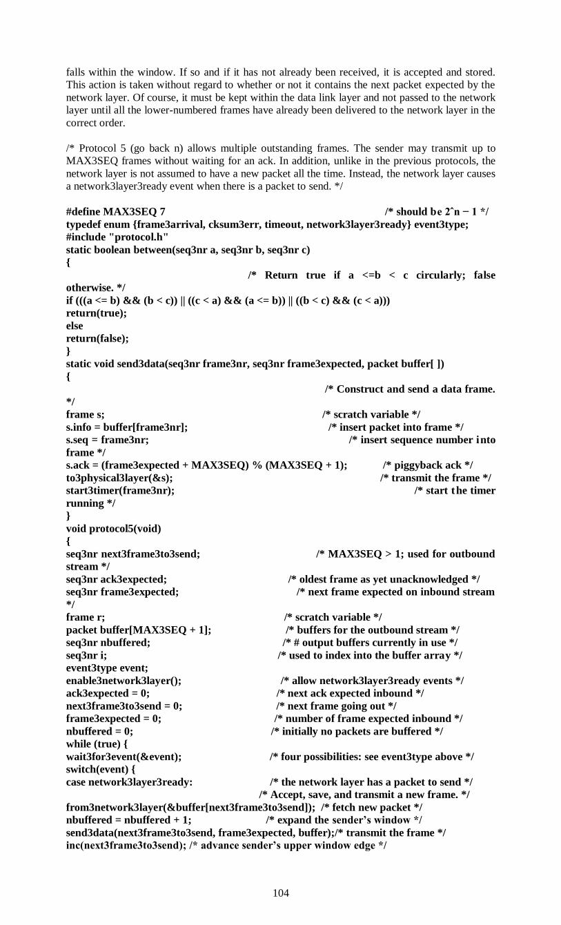
104
falls within the window. If so and if it has not already been received, it is accepted and stored.
This action is taken without regard to whether or not it contains the next packet expected by the
network layer. Of course, it must be kept within the data link layer and not passed to the network
layer until all the lower-numbered frames have already been delivered to the network layer in the
correct order.
/* Protocol 5 (go back n) allows multiple outstanding frames. The sender may transmit up to
MAX3SEQ frames without waiting for an ack. In addition, unlike in the previous protocols, the
network layer is not assumed to have a new packet all the time. Instead, the network layer causes
a network3layer3ready event when there is a packet to send. */
#define MAX3SEQ 7 /* should be 2ˆn − 1 */
typedef enum {frame3arrival, cksum3err, timeout, network3layer3ready} event3type;
#include "protocol.h"
static boolean between(seq3nr a, seq3nr b, seq3nr c)
{
/* Return true if a <=b < c circularly; false
otherwise. */
if (((a <= b) && (b < c)) || ((c < a) && (a <= b)) || ((b < c) && (c < a)))
return(true);
else
return(false);
}
static void send3data(seq3nr frame3nr, seq3nr frame3expected, packet buffer[ ])
{
/* Construct and send a data frame.
*/
frame s; /* scratch variable */
s.info = buffer[frame3nr]; /* insert packet into frame */
s.seq = frame3nr; /* insert sequence number into
frame */
s.ack = (frame3expected + MAX3SEQ) % (MAX3SEQ + 1); /* piggyback ack */
to3physical3layer(&s); /* transmit the frame */
start3timer(frame3nr); /* start the timer
running */
}
void protocol5(void)
{
seq3nr next3frame3to3send; /* MAX3SEQ > 1; used for outbound
stream */
seq3nr ack3expected; /* oldest frame as yet unacknowledged */
seq3nr frame3expected; /* next frame expected on inbound stream
*/
frame r; /* scratch variable */
packet buffer[MAX3SEQ + 1]; /* buffers for the outbound stream */
seq3nr nbuffered; /* # output buffers currently in use */
seq3nr i; /* used to index into the buffer array */
event3type event;
enable3network3layer(); /* allow network3layer3ready events */
ack3expected = 0; /* next ack expected inbound */
next3frame3to3send = 0; /* next frame going out */
frame3expected = 0; /* number of frame expected inbound */
nbuffered = 0; /* initially no packets are buffered */
while (true) {
wait3for3event(&event); /* four possibilities: see event3type above */
switch(event) {
case network3layer3ready: /* the network layer has a packet to send */
/* Accept, save, and transmit a new frame. */
from3network3layer(&buffer[next3frame3to3send]); /* fetch new packet */
nbuffered = nbuffered + 1; /* expand the sender’s window */
send3data(next3frame3to3send, frame3expected, buffer);/* transmit the frame */
inc(next3frame3to3send); /* advance sender’s upper window edge */
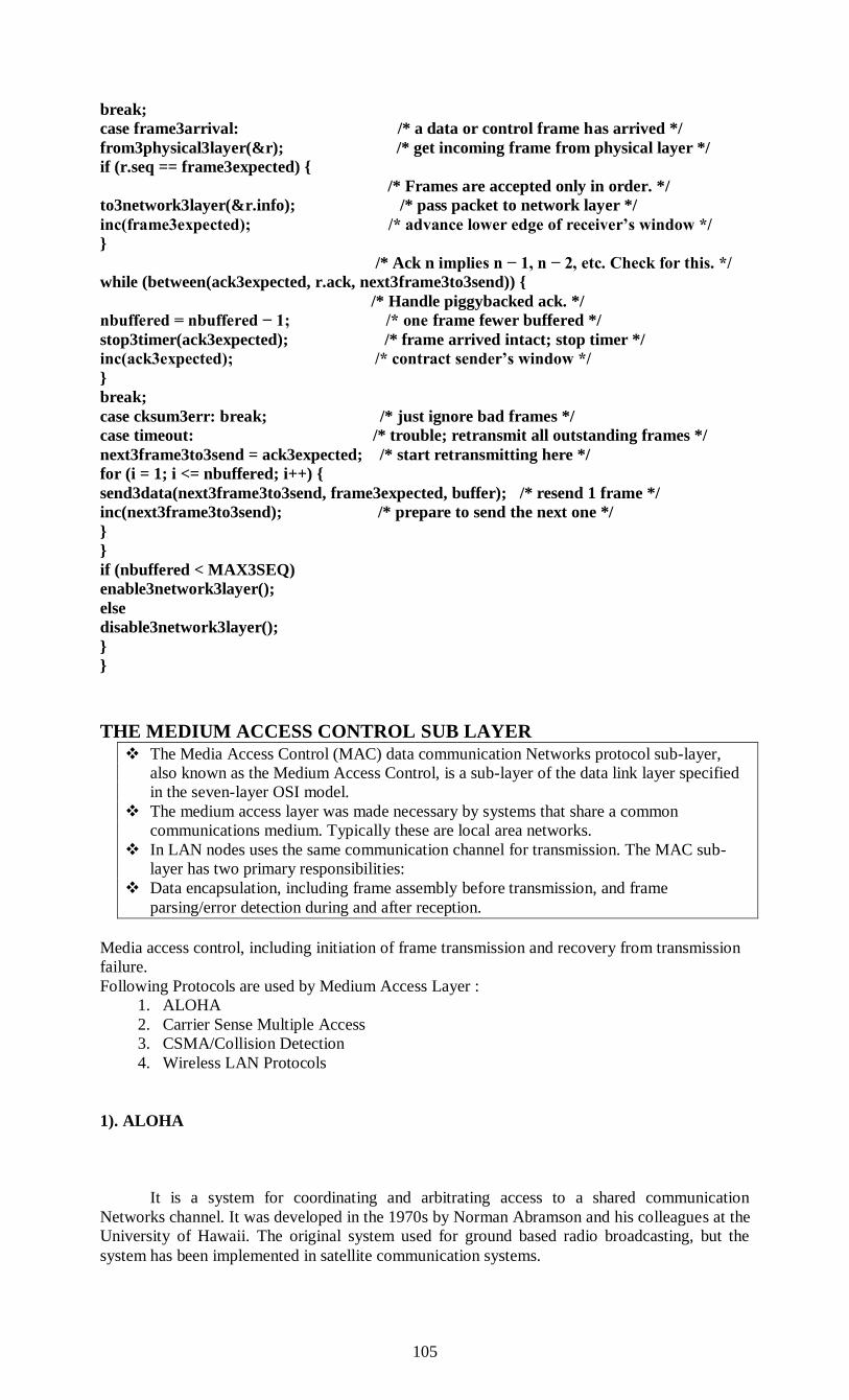
105
break;
case frame3arrival: /* a data or control frame has arrived */
from3physical3layer(&r); /* get incoming frame from physical layer */
if (r.seq == frame3expected) {
/* Frames are accepted only in order. */
to3network3layer(&r.info); /* pass packet to network layer */
inc(frame3expected); /* advance lower edge of receiver’s window */
}
/* Ack n implies n − 1, n − 2, etc. Check for this. */
while (between(ack3expected, r.ack, next3frame3to3send)) {
/* Handle piggybacked ack. */
nbuffered = nbuffered − 1; /* one frame fewer buffered */
stop3timer(ack3expected); /* frame arrived intact; stop timer */
inc(ack3expected); /* contract sender’s window */
}
break;
case cksum3err: break; /* just ignore bad frames */
case timeout: /* trouble; retransmit all outstanding frames */
next3frame3to3send = ack3expected; /* start retransmitting here */
for (i = 1; i <= nbuffered; i++) {
send3data(next3frame3to3send, frame3expected, buffer); /* resend 1 frame */
inc(next3frame3to3send); /* prepare to send the next one */
}
}
if (nbuffered < MAX3SEQ)
enable3network3layer();
else
disable3network3layer();
}
}
THE MEDIUM ACCESS CONTROL SUB LAYER
The Media Access Control (MAC) data communication Networks protocol sub-layer,
also known as the Medium Access Control, is a sub-layer of the data link layer specified
in the seven-layer OSI model.
The medium access layer was made necessary by systems that share a common
communications medium. Typically these are local area networks.
In LAN nodes uses the same communication channel for transmission. The MAC sub-
layer has two primary responsibilities:
Data encapsulation, including frame assembly before transmission, and frame
parsing/error detection during and after reception.
Media access control, including initiation of frame transmission and recovery from transmission
failure.
Following Protocols are used by Medium Access Layer :
1. ALOHA
2. Carrier Sense Multiple Access
3. CSMA/Collision Detection
4. Wireless LAN Protocols
1). ALOHA
It is a system for coordinating and arbitrating access to a shared communication
Networks channel. It was developed in the 1970s by Norman Abramson and his colleagues at the
University of Hawaii. The original system used for ground based radio broadcasting, but the
system has been implemented in satellite communication systems.

106
A shared communication system like ALOHA requires a method of handling collisions that
occur when two or more systems attempt to transmit on the channel at the same time.
In the ALOHA system, a node transmits whenever data is available to send. If another
node transmits at the same time, a collision occurs, and the frames that were transmitted are lost.
However, a node can listen to broadcasts on the medium, even its own, and determine whether
the frames were transmitted.
Aloha means "Hello". Aloha is a multiple access protocol at the datalink layer and proposes
how multiple terminals access the medium without interference or collision. In 1972 Roberts
developed a protocol that would increase the capacity of aloha two fold. The Slotted Aloha
protocol involves dividing the time interval into discrete slots and each slot interval corresponds
to the time period of one frame. This method requires synchronization between the sending
nodes to prevent collisions.
There are two different types of ALOHA:
(i) Pure ALOHA
(ii) slotted ALOHA
(i) Pure ALOHA
In pure ALOHA, the stations transmit frames whenever they have data to send.
When two or more stations transmit simultaneously, there is collision and the frames are
destroyed.
In pure ALOHA, whenever any station transmits a frame, it expects the
acknowledgement from the receiver.
If acknowledgement is not received within specified time, the station assumes that the
frame (or acknowledgement) has been destroyed.
If the frame is destroyed because of collision the station waits for a random amount of
time and sends it again. This waiting time must be random otherwise same frames will
collide again and again.
Therefore pure ALOHA dictates that when time-out period passes, each station must wait
for a random amount of time before resending its frame. This randomness will help avoid
more collisions.
Figure shows an example of frame collisions in pure ALOHA.
(ii) Slotted ALOHA
Slotted ALOHA was invented to improve the efficiency of pure ALOHA as chances of
collision in pure ALOHA are very high.
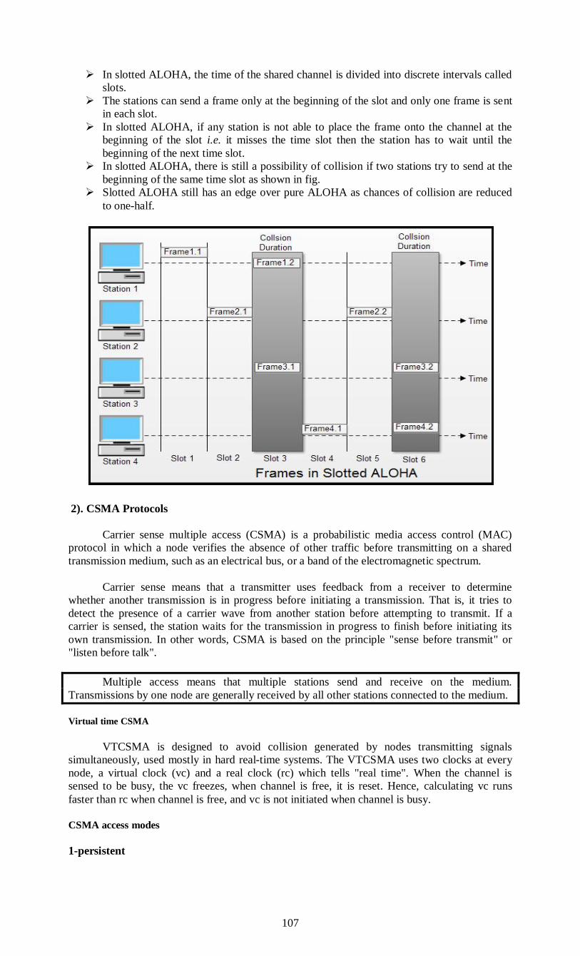
107
In slotted ALOHA, the time of the shared channel is divided into discrete intervals called
slots.
The stations can send a frame only at the beginning of the slot and only one frame is sent
in each slot.
In slotted ALOHA, if any station is not able to place the frame onto the channel at the
beginning of the slot i.e. it misses the time slot then the station has to wait until the
beginning of the next time slot.
In slotted ALOHA, there is still a possibility of collision if two stations try to send at the
beginning of the same time slot as shown in fig.
Slotted ALOHA still has an edge over pure ALOHA as chances of collision are reduced
to one-half.
2). CSMA Protocols
Carrier sense multiple access (CSMA) is a probabilistic media access control (MAC)
protocol in which a node verifies the absence of other traffic before transmitting on a shared
transmission medium, such as an electrical bus, or a band of the electromagnetic spectrum.
Carrier sense means that a transmitter uses feedback from a receiver to determine
whether another transmission is in progress before initiating a transmission. That is, it tries to
detect the presence of a carrier wave from another station before attempting to transmit. If a
carrier is sensed, the station waits for the transmission in progress to finish before initiating its
own transmission. In other words, CSMA is based on the principle "sense before transmit" or
"listen before talk".
Multiple access means that multiple stations send and receive on the medium.
Transmissions by one node are generally received by all other stations connected to the medium.
Virtual time CSMA
VTCSMA is designed to avoid collision generated by nodes transmitting signals
simultaneously, used mostly in hard real-time systems. The VTCSMA uses two clocks at every
node, a virtual clock (vc) and a real clock (rc) which tells "real time". When the channel is
sensed to be busy, the vc freezes, when channel is free, it is reset. Hence, calculating vc runs
faster than rc when channel is free, and vc is not initiated when channel is busy.
CSMA access modes
1-persistent
108
1-persistent CSMA is an aggressive transmission algorithm. When the sender (station) is
ready to transmit data, it senses the transmission medium for idle or busy. If idle, then it
transmits immediately. If busy, then it senses the transmission medium continuously until it
becomes idle, then transmits the message (a frame) unconditionally (i.e. with probability=1). In
case of a collision, the sender waits for a random period of time and attempts to transmit again
unconditionally (i.e. with probability=1). 1-persistent CSMA is used in CSMA/CD systems
including Ethernet.
Non-persistent
Non persistent CSMA is a non aggressive transmission algorithm. When the sender
(station) is ready to transmit data, it senses the transmission medium for idle or busy. If idle, then
it transmits immediately. If busy, then it waits for a random period of time (during which it does
not sense the transmission medium) before repeating the whole logic cycle (which started with
sensing the transmission medium for idle or busy) again. This approach reduces collision, results
in overall higher medium throughput but with a penalty of longer initial delay compared to 1–
persistent.
P-persistent
This is an approach between 1-persistent and non-persistent CSMA access modes. When
the sender (station) is ready to transmit data, it senses the transmission medium for idle or busy.
If idle, then it transmits immediately. If busy, then it senses the transmission medium
continuously until it becomes idle, then transmits a frame with probability p. If the sender
chooses not to transmit (the probability of this event is 1-p), the sender waits until the next
available time slot. If the transmission medium is still not busy, it transmits again with the same
probability p. This probabilistic hold-off repeats until the frame is finally transmitted or when the
medium is found to become busy again (i.e. some other sender has already started transmitting
their data). In the latter case the sender repeats the whole logic cycle (which started with sensing
the transmission medium for idle or busy) again. p-persistent CSMA is used in CSMA/CA
systems including Wi-Fi and other packet radio systems.
O-persistent
Each station is assigned a transmission order by a supervisor station. When medium goes
idle, stations wait for their time slot in accordance with their assigned transmission order. The
station assigned to transmit first transmits immediately. The station assigned to transmit second
waits one time slot (but by that time the first station has already started transmitting). Stations
monitor the medium for transmissions from other stations and update their assigned order with
each detected transmission (i.e. they move one position closer to the front of the queue). O-
persistent CSMA is used by CobraNet, LonWorks and the controller area network.
CSMA with collision detection
CSMA/CD is used to improve CSMA performance by terminating transmission as soon
as a collision is detected, thus shortening the time required before a retry can be attempted. is a
media access control method used most notably in local area networking using early Ethernet
technology. It uses a carrier sensing scheme in which a transmitting data station detects other
signals while transmitting a frame, and stops transmitting that frame, transmits a jam signal, and
then waits for a random time interval before trying to resend the frame.
CSMA/CD is modifications of pure carrier sense multiple accesses (CSMA). CSMA/CD
is used to improve CSMA performance by terminating transmission as soon as a collision is
detected, thus shortening the time required before a retry can be attempted.
Main procedure
1. Is my frame ready for transmission? If yes, it goes on to the next point.
2. Is medium idle? If not, wait until it becomes ready
3. Start transmitting.
4. Did a collision occur? If so, go to collision detected procedure.
5. Reset retransmission counters and end frame transmission.

109
Collision detected procedure
6. Continue transmission (with a jam signal instead of frame header/data/CRC) until
minimum packet time is reached to ensure that all receivers detect the collision.
7. Increment retransmission counter.
8. Was the maximum number of transmission attempts reached? If so, abort transmission.
9. Calculate and wait random backoff period based on number of collisions.
10. Re-enter main procedure at stage 1.
CSMA with collision avoidance
In CSMA/CA collision avoidance is used to improve the performance of CSMA by
attempting to be less "greedy" on the channel. If the channel is sensed busy before transmission
then the transmission is deferred for a "random" interval. This reduces the probability of
collisions on the channel.
It is particularly important for wireless networks, where the collision detection of the
alternative CSMA/CD is unreliable due to the hidden node problem. CSMA/CA is a protocol
that operates in the Data Link Layer (Layer 2) of the OSI model.
Collision avoidance is used to improve the performance of the CSMA method by attempting to
divide the channel somewhat equally among all transmitting nodes within the collision domain.
1. Carrier Sense: prior to transmitting, a node first listens to the shared medium (such as
listening for wireless signals in a wireless network) to determine whether another node is
transmitting or not. Note that the hidden node problem means another node may be
transmitting which goes undetected at this stage.
2. Collision Avoidance: if another node was heard, we wait for a period of time for the
node to stop transmitting before listening again for a free communications channel.
Request to Send/Clear to Send (RTS/CTS) may optionally be used at this point
to mediate access to the shared medium. This goes some way to alleviating the
problem of hidden nodes because, for instance, in a wireless network, the Access
Point only issues a Clear to Send to one node at a time. However, wireless 802.11
implementations do not typically implement RTS/CTS for all transmissions; they
may turn it off completely, or at least not use it for small packets (the overhead of
RTS, CTS and transmission is too great for small data transfers).
Transmission: if the medium was identified as being clear or the node received a
CTS to explicitly indicate it can send, it sends the frame in its entirety. Unlike
CSMA/CD, it is very challenging for a wireless node to listen at the same time as
it transmits (its transmission will dwarf any attempt to listen). Continuing the
wireless example, the node awaits receipt of an acknowledgement packet from the
Access Point to indicate the packet was received and check summed correctly. If
such acknowledgement does not arrive after a timely manner, it assumes the
packet collided with some other transmission, causing the node to enter a period
of binary exponential backoff prior to attempting to re-transmit.
ETHERNET
Digital Equipment Corporation and Xerox (DIX) worked together to develop the first
Ethernet standards.
Ethernet is a passive, contention-based broadcast technology that uses baseband
signaling. Ethernet topology, which is based on bus and bus-star physical configurations, is
currently the most frequently configured LAN network architecture.
A bus is a common pathway (usually copper wire or fiber cable) between multiple
devices such as computers. A bus is often used as a backbone between devices. It is a technology
that has been evolving for more than 25 years and is still evolving to meet the ever increasing
and changing needs of the internetworking community.
Digital Equipment Corporation and Xerox (DIX) worked together to develop the first
Ethernet standards. These standards are the DIX Ethernet standards and are still in use today. As
110
Ethernet topology became more popular, industry-wide standards became necessary. In 1985, the
IEEE adopted the current Ethernet standards. These standards are called the IEEE 802.2 and
802.3 standards. They differ slightly from the DIX standards, but both define the protocols for
the physical and data link layers of the OSI Model. These standards include cabling
specifications, frame format, and network access conventions.
Ethernet is a passive, contention-based broadcast technology that uses baseband
signaling. Baseband signaling uses the entire bandwidth of a cable for a single transmission.
Only one signal can be transmitted at a time and every device on the shared network hears
broadcast transmissions. Passive technology means that there is no one device controlling the
network. Contention-based means that every device must compete with every o ther device for
access to the shared network. In other words, devices take turns. They can transmit only when no
other device is transmitting.
Ethernet popularity is a result of several factors. Ethernet technology is:
· Inexpensive
· Easy to install, maintain, troubleshoot and expand
· A widely accepted industry standard, which means compatibility and equipment access
are less of an issue
· Structured to allow compatibility with network operating systems
(NOS)
· Very reliable
Ethernet is a broadcast topology that may be structured as a physical bus or physical star with a
logical bus.
Ethernet Cables
Generally, some people use the term "Ethernet" or ether refers to cable. Ethernet was the
original product designed by Xerox PARC based on Bob Metcalfe's idea. It was later upgraded
to 10 Mbps by Xerox, Intel and DEC.
This formed the basis for the IEEE 802.3 standard, which then became an ISO standard.
Actually, the Ethernet was the implementation of standard 802.3 between the computers of
Hawaiian Islands.
Cabling for 802.3: The term Ethernet refers to a network of cables. Various types of
cables are being used in different 802.3 implementations.
The following four cable types are the most common among them:
1. 10Base5 cable. 10Base5 cable or "Thick Ethernet" or Thicknet is the cable which is
the oldest in the category. it is called as thicknet because of the use of thick coaxial cable. The
cable is marked after each 2.5 meters. The thicknet uses bus topology. These marks are provided
for attaching tap points. The connections to this cable are made by "Vampire Taps". In this type
of connection, a pin is carefully forced half a way into the coaxial cable core. The cable operates
at 10Mbps and it can support a maximum segment length of 500 meters. It supports 100 nodes
per segment. 10Base5 cable allows, at maximum, five segments (each of max of 500 meter) to be
connected. These segment are connected with the help of repeaters. Therefore four repeaters are
allowed to be used providing the effective length of2.5 km.
It make use of transceiver (transmitter/receiver) connected via a vampire tap. The
transceiver is responsible for transmitting, receiving and detecting collisions. This transceiver is
connected to the station via a transceiver cable that provides separate path for sending and
receiving.
2. 10Base2 Cable. 10Base2 cable also called "Thin Ethernet" or Thinnet or cheapnet or
cheapernet, was designed after the thick Ethernet cable. This type of cable is usually thin,
flexible and bends easily. It also make use of bus topology. It is also a coaxial cable that is
having a smaller diameter than the 10Base5 cable. The connections to this cable are made by
BNC connectors or UTP connectors. The connections are created by forming T junctions. These
are easier to use and more reliable than vampire connections. The Ethernet based on this type of
cables is cheaper and easy to install but it can run for 200 meters and it supports 30 nodes per
segment. In both of these network cables, detecting cable breaks, bad taps or loose connections
111
can be a major problem. Here, a special technique, called "Time Domain Reflectometry" is
used to detect such kind of errors.
3. 10BaseT Cable. l0BaseT cable or "Twisted Pair" Cable is cheapest and easiest to
maintain. This type of cabling is most popular among local area networks. It make use of
unshielded twisted pair and provides maximum segment length of 100 m. It make use of start
topology. In this type of network, every station is having a wired link to a central device, called
"Hub". Telephone company twisted pair cable of category 5 is used in this type of network. This
is an older and known technology of connections. It can support 1024 nodes per cable segment.
The maximum length of a segment from hub to station can be 150 meters. This type of networks
involves the extra cost of hubs.
4. l0BaseF Cable. 10BaseF cable or "Fiber Optics Cable" is the most efficient and fastest
cable in the category of cables for 802 LANs. The fiber optic cable is very expensive as
compared to above discussed cables but it offers a very high data transmission speed and noise
immunity. This type of cabling is preferred for running networks between buildings or widely
separated hubs. It has the highest length per cable segment i.e. 2000 meters and it can support
1024 nodes per cable segment.
Gigabit Ethernet
Gigabit Ethernet provides the data rate of 1 Gbps or 1000 Mbps. IEEE created Gigabit
Ethernet under the name 802.3z.
• It is compatible with Standard or Fast Ethernet.
• It also uses similarly 48 bit hexadecimal addressing scheme.
• The frame format is also similar to standard Ethernet.
• It operates in both half-duplex and full duplex mode.
• In half duplex mode, CSMNCD access method IS used whereas in full duplex mode CSMNCD
is not required.
MAC Sublayer Functions
MAC sub layer remains almost same in Gigabit Ethernet. There are two distinct approaches for
medium access: half-duplex and full duplex.
• In full duplex mode
(a) There is no collision and CSMNCD is not used.
(b) Each computer is connected to central switch or other switches as shown in fig.
(c) In this mode, each switch has buffers for each input port in which data are stored until they
are transmitted.
(d) The maximum length of the cable is determined by the signal attenuation in the cable.
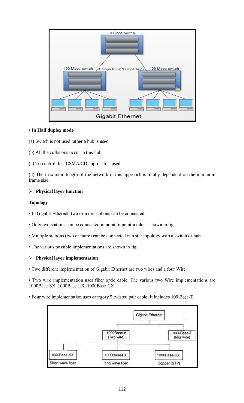
112
• In Half duplex mode
(a) Switch is not used rather a hub is used.
(b) All the collisions occur in this hub.
(c) To control this, CSMA/CD approach is used.
(d) The maximum length of the network in this approach is totally dependent on the minimum
frame size.
Physical layer function
Topology
• In Gigabit Ethernet, two or more stations can be connected.
• Only two stations can be connected in point to point mode as shown in fig.
• Multiple stations (two or more) can be connected in a star topology with a switch or hub.
• The various possible implementations are shown in fig.
Physical layer implementation
• Two different implementation of Gigabit Ethernet are two wires and a four Wire.
• Two wire implementation uses fiber optic cable. The various two Wire implementations are
1000Base-SX, 1000Base-LX, 1000Base-CX
• Four wire implementation uses category 5 twisted pair cable. It includes 100 Base-T.

113
1000 Base-SX
(a) It uses multimode optical fiber with 2 wires.
(b) It uses short wave laser.
(c) The maximum length of segment supported by 1000Base-SX is 550 meters.
(d) It uses 8B/10B block encoding and NRZ line encoding as shown in Fig.
1000 Base-LX
• It uses multimode or single mode optical fiber (2 wires).
• It makes use of long wave laser.
• The maximum length of segment supported is 550 meters (in multimode) and 5000 meters (in
single mode).
• It also uses 8B/IOB block encoding with NRZ line encoding.
1000 Base-CX
• It uses shielded twisted pair cable (2 wires) that carry electrical signal.
• The maximum length of segment supported by it is~5 meters.
• It also uses 8B/6B blocking encoding and NRZ line encoding.
1000 Base-T
• It uses category 5 UTP (4 wires).
• The maximum segment length supported is 100 meters.
• It makes use of 4D-P AM5 encoding to reduce the bandwidth.
• In 4D-PAM 5 encoding, are four wires are evolved input and output.
• Each wire carries 250 Mbps which is in the range for cat 5 UTP cable.
Fast Ethernet
Fast Ethernet is a version of Ethernet with a 100 Mbps data rate.
• Fast Ethernet was designed to compete with LAN protocols such as FDDI or Fiber Channel.
• IEEE created Fast Ethernet under the name 802.3u.
• The frame format of fast Ethernet is same as that of the traditional Ethernet.

114
• Addressing scheme of Fast Ethernet is also same as that of traditional Ethernet.
• It also makes use of 48 bit hexadecimal address.
IEEE has designed two categories of Fast Ethernet: 100Base-X and 100BaseT4.
100Base-X uses two cables between the station and the hub and 100Base-T4 uses four cables
between the station and hub.
100 Base-TX
(a) 1OOBase-TX uses two pairs of category 5 unshielded twisted pair (UTP) or two pairs of
shielded twisted pair (STP) cables to connect a station to the hub.
(b) One pair is used to carry frames from the station to the hub and the other to carry frames from
the hub to the station.
(c) The distance between hub and station should be less than 100 meters.
(d) For this implementation, the MLT-3 scheme is used. However as MLT-3 is not a self
synchronous line coding scheme, 4B/5B block coding is used to provide bit synchronization.
(e) This creates a data rate of 125 Mbps, which is fed into MLT-3 for encoding.
(f) The encoding and decoding is implemented in two steps as shown in Fig.
100 Base-FX
(a) It users two pairs fiber-optic cables.
(b) One pair carries frame from the station to the hub and the other from hub to the station.
(c) The distance between the station and the hub (or switch) should be less than 2000 meters.
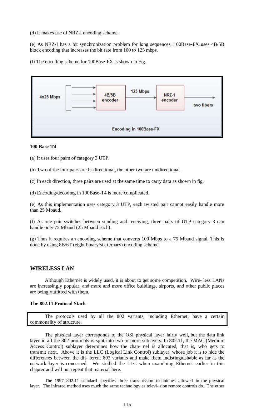
115
(d) It makes use of NRZ-I encoding scheme.
(e) As NRZ-I has a bit synchronization problem for long sequences, 100Base-FX uses 4B/5B
block encoding that increases the bit rate from 100 to 125 mbps.
(f) The encoding scheme for 100Base-FX is shown in Fig.
100 Base-T4
(a) It uses four pairs of category 3 UTP.
(b) Two of the four pairs are bi-directional, the other two are unidirectional.
(c) In each direction, three pairs are used at the same time to carry data as shown in fig.
(d) Encoding/decoding in 100Base-T4 is more complicated.
(e) As this implementation uses category 3 UTP, each twisted pair cannot easily handle more
than 25 Mbaud.
(f) As one pair switches between sending and receiving, three pairs of UTP category 3 can
handle only 75 Mbaud (25 Mbaud each).
(g) Thus it requires an encoding scheme that converts 100 Mbps to a 75 Mbaud signal. This is
done by using 8B/6T (eight binary/six ternary) encoding scheme.
WIRELESS LAN
Although Ethernet is widely used, it is about to get some competition. Wire- less LANs
are increasingly popular, and more and more office buildings, airports, and other public places
are being outfitted with them.
The 802.11 Protocol Stack
The protocols used by all the 802 variants, including Ethernet, have a certain
commonality of structure.
The physical layer corresponds to the OSI physical layer fairly well, but the data link
layer in all the 802 protocols is split into two or more sublayers. In 802.11, the MAC (Medium
Access Control) sublayer determines how the chan- nel is allocated, that is, who gets to
transmit next. Above it is the LLC (Logical Link Control) sublayer, whose job it is to hide the
differences between the dif- ferent 802 variants and make them indistinguishable as far as the
network layer is concerned. We studied the LLC when examining Ethernet earlier in this
chapter and will not repeat that material here.
The 1997 802.11 standard specifies three transmission techniques allowed in the physical
layer. The infrared method uses much the same technology as televi- sion remote controls do. The other
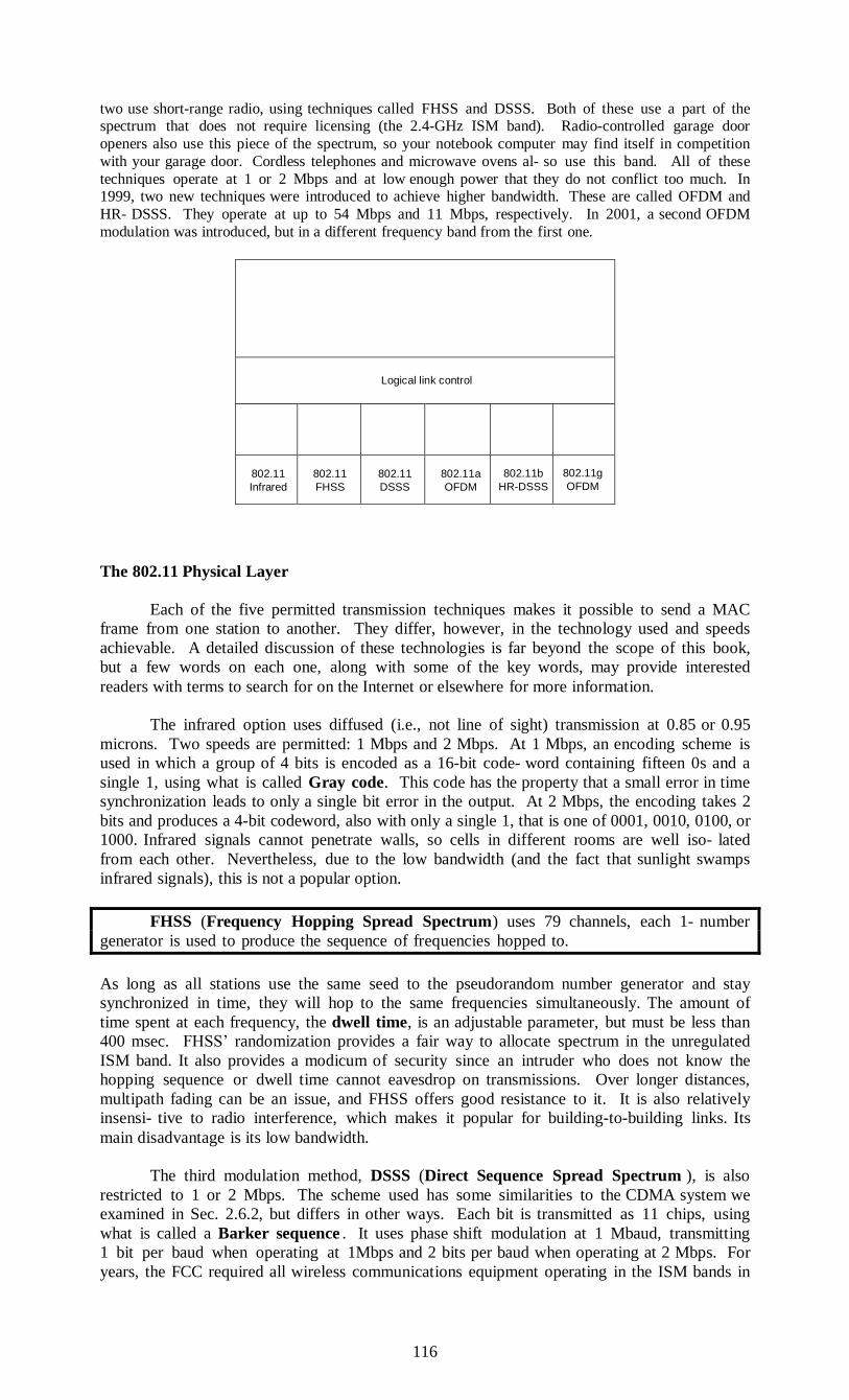
116
two use short-range radio, using techniques called FHSS and DSSS. Both of these use a part of the spectrum that does not require licensing (the 2.4-GHz ISM band). Radio-controlled garage door
openers also use this piece of the spectrum, so your notebook computer may find itself in competition
with your garage door. Cordless telephones and microwave ovens al- so use this band. All of these
techniques operate at 1 or 2 Mbps and at low enough power that they do not conflict too much. In 1999, two new techniques were introduced to achieve higher bandwidth. These are called OFDM and
HR- DSSS. They operate at up to 54 Mbps and 11 Mbps, respectively. In 2001, a second OFDM
modulation was introduced, but in a different frequency band from the first one.
Logical link control
802.11
Infrared
802.11
FHSS
802.11
DSSS
802.11a
OFDM
802.11b
HR-DSSS
802.11g
OFDM
The 802.11 Physical Layer
Each of the five permitted transmission techniques makes it possible to send a MAC
frame from one station to another. They differ, however, in the technology used and speeds
achievable. A detailed discussion of these technologies is far beyond the scope of this book,
but a few words on each one, along with some of the key words, may provide interested
readers with terms to search for on the Internet or elsewhere for more information.
The infrared option uses diffused (i.e., not line of sight) transmission at 0.85 or 0.95
microns. Two speeds are permitted: 1 Mbps and 2 Mbps. At 1 Mbps, an encoding scheme is
used in which a group of 4 bits is encoded as a 16-bit code- word containing fifteen 0s and a
single 1, using what is called Gray code. This code has the property that a small error in time
synchronization leads to only a single bit error in the output. At 2 Mbps, the encoding takes 2
bits and produces a 4-bit codeword, also with only a single 1, that is one of 0001, 0010, 0100, or
1000. Infrared signals cannot penetrate walls, so cells in different rooms are well iso- lated
from each other. Nevertheless, due to the low bandwidth (and the fact that sunlight swamps
infrared signals), this is not a popular option.
FHSS (Frequency Hopping Spread Spectrum) uses 79 channels, each 1- number
generator is used to produce the sequence of frequencies hopped to.
As long as all stations use the same seed to the pseudorandom number generator and stay
synchronized in time, they will hop to the same frequencies simultaneously. The amount of
time spent at each frequency, the dwell time, is an adjustable parameter, but must be less than
400 msec. FHSS’ randomization provides a fair way to allocate spectrum in the unregulated
ISM band. It also provides a modicum of security since an intruder who does not know the
hopping sequence or dwell time cannot eavesdrop on transmissions. Over longer distances,
multipath fading can be an issue, and FHSS offers good resistance to it. It is also relatively
insensi- tive to radio interference, which makes it popular for building-to-building links. Its
main disadvantage is its low bandwidth.
The third modulation method, DSSS (Direct Sequence Spread Spectrum ), is also
restricted to 1 or 2 Mbps. The scheme used has some similarities to the CDMA system we
examined in Sec. 2.6.2, but differs in other ways. Each bit is transmitted as 11 chips, using
what is called a Barker sequence . It uses phase shift modulation at 1 Mbaud, transmitting
1 bit per baud when operating at 1Mbps and 2 bits per baud when operating at 2 Mbps. For
years, the FCC required all wireless communications equipment operating in the ISM bands in
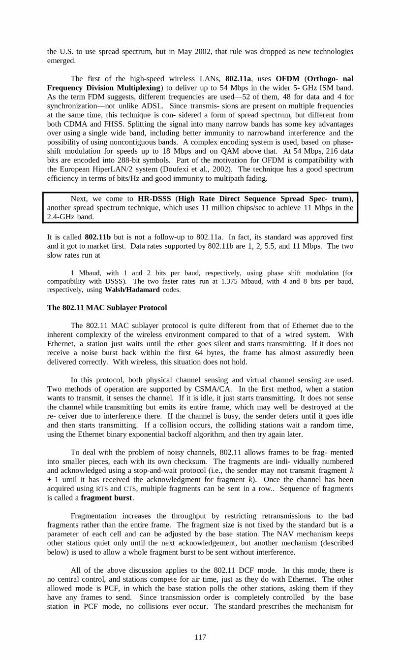
117
the U.S. to use spread spectrum, but in May 2002, that rule was dropped as new technologies
emerged.
The first of the high-speed wireless LANs, 802.11a, uses OFDM (Orthogo- nal
Frequency Division Multiplexing) to deliver up to 54 Mbps in the wider 5- GHz ISM band.
As the term FDM suggests, different frequencies are used—52 of them, 48 for data and 4 for
synchronization—not unlike ADSL. Since transmis- sions are present on multiple frequencies
at the same time, this technique is con- sidered a form of spread spectrum, but different from
both CDMA and FHSS. Splitting the signal into many narrow bands has some key advantages
over using a single wide band, including better immunity to narrowband interference and the
possibility of using noncontiguous bands. A complex encoding system is used, based on phase-
shift modulation for speeds up to 18 Mbps and on QAM above that. At 54 Mbps, 216 data
bits are encoded into 288-bit symbols. Part of the motivation for OFDM is compatibility with
the European HiperLAN/2 system (Doufexi et al., 2002). The technique has a good spectrum
efficiency in terms of bits/Hz and good immunity to multipath fading.
Next, we come to HR-DSSS (High Rate Direct Sequence Spread Spec- trum),
another spread spectrum technique, which uses 11 million chips/sec to achieve 11 Mbps in the
2.4-GHz band.
It is called 802.11b but is not a follow-up to 802.11a. In fact, its standard was approved first
and it got to market first. Data rates supported by 802.11b are 1, 2, 5.5, and 11 Mbps. The two
slow rates run at
1 Mbaud, with 1 and 2 bits per baud, respectively, using phase shift modulation (for
compatibility with DSSS). The two faster rates run at 1.375 Mbaud, with 4 and 8 bits per baud,
respectively, using Walsh/Hadamard codes.
The 802.11 MAC Sublayer Protocol
The 802.11 MAC sublayer protocol is quite different from that of Ethernet due to the
inherent complexity of the wireless environment compared to that of a wired system. With
Ethernet, a station just waits until the ether goes silent and starts transmitting. If it does not
receive a noise burst back within the first 64 bytes, the frame has almost assuredly been
delivered correctly. With wireless, this situation does not hold.
In this protocol, both physical channel sensing and virtual channel sensing are used.
Two methods of operation are supported by CSMA/CA. In the first method, when a station
wants to transmit, it senses the channel. If it is idle, it just starts transmitting. It does not sense
the channel while transmitting but emits its entire frame, which may well be destroyed at the
re- ceiver due to interference there. If the channel is busy, the sender defers until it goes idle
and then starts transmitting. If a collision occurs, the colliding stations wait a random time,
using the Ethernet binary exponential backoff algorithm, and then try again later.
To deal with the problem of noisy channels, 802.11 allows frames to be frag- mented
into smaller pieces, each with its own checksum. The fragments are indi- vidually numbered
and acknowledged using a stop-and-wait protocol (i.e., the sender may not transmit fragment k
+ 1 until it has received the acknowledgment for fragment k). Once the channel has been
acquired using RTS and CTS, multiple fragments can be sent in a row.. Sequence of fragments
is called a fragment burst.
Fragmentation increases the throughput by restricting retransmissions to the bad
fragments rather than the entire frame. The fragment size is not fixed by the standard but is a
parameter of each cell and can be adjusted by the base station. The NAV mechanism keeps
other stations quiet only until the next acknowledgement, but another mechanism (described
below) is used to allow a whole fragment burst to be sent without interference.
All of the above discussion applies to the 802.11 DCF mode. In this mode, there is
no central control, and stations compete for air time, just as they do with Ethernet. The other
allowed mode is PCF, in which the base station polls the other stations, asking them if they
have any frames to send. Since transmission order is completely controlled by the base
station in PCF mode, no collisions ever occur. The standard prescribes the mechanism for
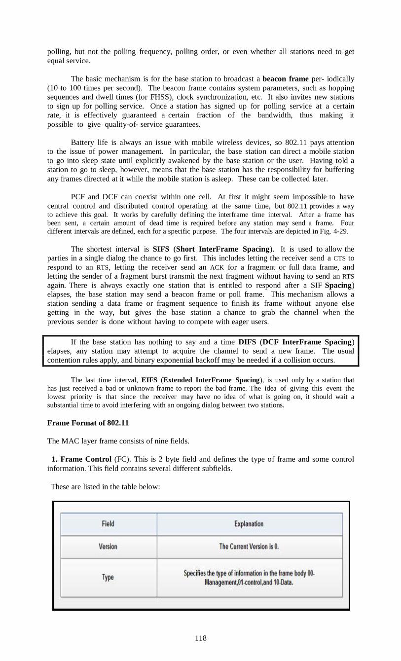
118
polling, but not the polling frequency, polling order, or even whether all stations need to get
equal service.
The basic mechanism is for the base station to broadcast a beacon frame per- iodically
(10 to 100 times per second). The beacon frame contains system parameters, such as hopping
sequences and dwell times (for FHSS), clock synchronization, etc. It also invites new stations
to sign up for polling service. Once a station has signed up for polling service at a certain
rate, it is effectively guaranteed a certain fraction of the bandwidth, thus making it
possible to give quality-of- service guarantees.
Battery life is always an issue with mobile wireless devices, so 802.11 pays attention
to the issue of power management. In particular, the base station can direct a mobile station
to go into sleep state until explicitly awakened by the base station or the user. Having told a
station to go to sleep, however, means that the base station has the responsibility for buffering
any frames directed at it while the mobile station is asleep. These can be collected later.
PCF and DCF can coexist within one cell. At first it might seem impossible to have
central control and distributed control operating at the same time, but 802.11 provides a way
to achieve this goal. It works by carefully defining the interframe time interval. After a frame has
been sent, a certain amount of dead time is required before any station may send a frame. Four
different intervals are defined, each for a specific purpose. The four intervals are depicted in Fig. 4-29.
The shortest interval is SIFS (Short InterFrame Spacing). It is used to allow the
parties in a single dialog the chance to go first. This includes letting the receiver send a CTS to
respond to an RTS, letting the receiver send an ACK for a fragment or full data frame, and
letting the sender of a fragment burst transmit the next fragment without having to send an RTS
again. There is always exactly one station that is entitled to respond after a SIF Spacing)
elapses, the base station may send a beacon frame or poll frame. This mechanism allows a
station sending a data frame or fragment sequence to finish its frame without anyone else
getting in the way, but gives the base station a chance to grab the channel when the
previous sender is done without having to compete with eager users.
If the base station has nothing to say and a time DIFS (DCF InterFrame Spacing)
elapses, any station may attempt to acquire the channel to send a new frame. The usual
contention rules apply, and binary exponential backoff may be needed if a collision occurs.
The last time interval, EIFS (Extended InterFrame Spacing), is used only by a station that
has just received a bad or unknown frame to report the bad frame. The idea of giving this event the
lowest priority is that since the receiver may have no idea of what is going on, it should wait a
substantial time to avoid interfering with an ongoing dialog between two stations.
Frame Format of 802.11
The MAC layer frame consists of nine fields.
1. Frame Control (FC). This is 2 byte field and defines the type of frame and some control
information. This field contains several different subfields.
These are listed in the table below:
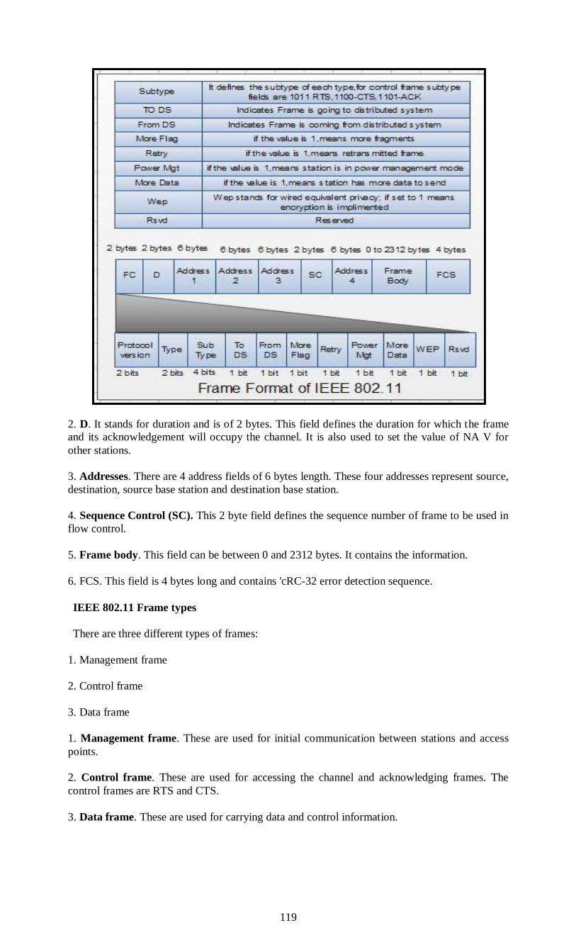
119
2. D. It stands for duration and is of 2 bytes. This field defines the duration for which the frame
and its acknowledgement will occupy the channel. It is also used to set the value of NA V for
other stations.
3. Addresses. There are 4 address fields of 6 bytes length. These four addresses represent source,
destination, source base station and destination base station.
4. Sequence Control (SC). This 2 byte field defines the sequence number of frame to be used in
flow control.
5. Frame body. This field can be between 0 and 2312 bytes. It contains the information.
6. FCS. This field is 4 bytes long and contains 'cRC-32 error detection sequence.
IEEE 802.11 Frame types
There are three different types of frames:
1. Management frame
2. Control frame
3. Data frame
1. Management frame. These are used for initial communication between stations and access
points.
2. Control frame. These are used for accessing the channel and acknowledging frames. The
control frames are RTS and CTS.
3. Data frame. These are used for carrying data and control information.
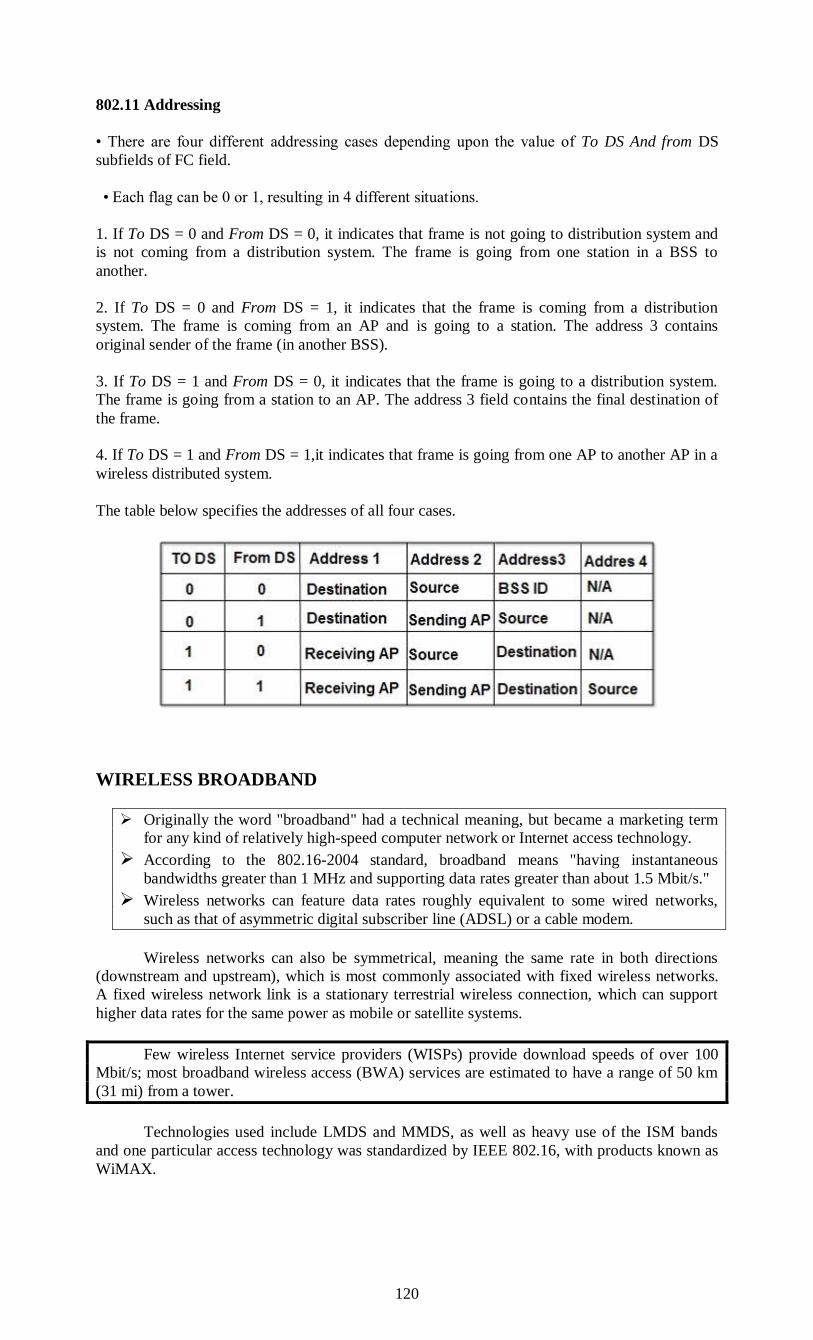
120
802.11 Addressing
• There are four different addressing cases depending upon the value of To DS And from DS
subfields of FC field.
• Each flag can be 0 or 1, resulting in 4 different situations.
1. If To DS = 0 and From DS = 0, it indicates that frame is not going to distribution system and
is not coming from a distribution system. The frame is going from one station in a BSS to
another.
2. If To DS = 0 and From DS = 1, it indicates that the frame is coming from a distribution
system. The frame is coming from an AP and is going to a station. The address 3 contains
original sender of the frame (in another BSS).
3. If To DS = 1 and From DS = 0, it indicates that the frame is going to a distribution system.
The frame is going from a station to an AP. The address 3 field contains the final destination of
the frame.
4. If To DS = 1 and From DS = 1,it indicates that frame is going from one AP to another AP in a
wireless distributed system.
The table below specifies the addresses of all four cases.
WIRELESS BROADBAND
Originally the word "broadband" had a technical meaning, but became a marketing term
for any kind of relatively high-speed computer network or Internet access technology.
According to the 802.16-2004 standard, broadband means "having instantaneous
bandwidths greater than 1 MHz and supporting data rates greater than about 1.5 Mbit/s."
Wireless networks can feature data rates roughly equivalent to some wired networks,
such as that of asymmetric digital subscriber line (ADSL) or a cable modem.
Wireless networks can also be symmetrical, meaning the same rate in both directions
(downstream and upstream), which is most commonly associated with fixed wireless networks.
A fixed wireless network link is a stationary terrestrial wireless connection, which can support
higher data rates for the same power as mobile or satellite systems.
Few wireless Internet service providers (WISPs) provide download speeds of over 100
Mbit/s; most broadband wireless access (BWA) services are estimated to have a range of 50 km
(31 mi) from a tower.
Technologies used include LMDS and MMDS, as well as heavy use of the ISM bands
and one particular access technology was standardized by IEEE 802.16, with products known as
WiMAX.
121
802.16e-2005 Technology
The 802.16 standard essentially standardizes two aspects of the air interface – the physical layer
(PHY) and the media access control (MAC) layer. This section provides an overview of the
technology employed in these two layers in the mobile 802.16e specification.
PHY
802.16e uses scalable OFDMA to carry data, supporting channel bandwidths of between
1.25 MHz and 20 MHz, with up to 2048 subcarriers. It supports adaptive modulation and coding,
so that in conditions of good signal, a highly efficient 64 QAM coding scheme is used, whereas
when the signal is poorer, a more robust BPSK coding mechanism is used. In intermediate
conditions, 16 QAM and QPSK can also be employed. Other PHY features include support for
multiple-input multiple-output (MIMO) antennas in order to provide good non-line-of-sight
propagation (NLOS) characteristics (or higher bandwidth) and hybrid automatic repeat request
(HARQ) for good error correction performance.
Although the standards allow operation in any band from 2 to 66 GHz, mobile operation
is best in the lower bands which are also the most crowded, and therefore most expensive.
MAC
The 802.16 MAC describes a number of Convergence Sublayers which describe how
wireline technologies such as Ethernet, Asynchronous Transfer Mode (ATM) and Internet
Protocol (IP) are encapsulated on the air interface, and how data is classified, etc. It also
describes how secure communications are delivered, by using secure key exchange during
authentication, and encryption using Advanced Encryption Standard (AES) or Data Encryption
Standard (DES) during data transfer. Further features of the MAC layer include power saving
mechanisms (using sleep mode and idle mode) and handover mechanisms.
A key feature of 802.16 is that it is a connection-oriented technology. The subscriber
station (SS) cannot transmit data until it has been allocated a channel by the base station (BS).
This allows 802.16e to provide strong support for quality of service (QoS).
QoS
Quality of service (QoS) in 802.16e is supported by allocating each connection between
the SS and the BS (called a service flow in 802.16 terminologies) to a specific QoS class. In
802.16e, there are 5 QoS classes.
Erecting a big antenna on a hill just outside of town is much easier and cheaper than
digging many trenches and stringing cables. Thus, companies have begun to experiment with
providing multimegabit wireless communication services for voice, Internet, movies on demand,
etc.
To stimulate the market, IEEE formed a group to standardize a broadband wireless
metropolitan area network. The next number available in the 802 numbering space was 802.16,
so the standard got this number. Informally the technology is called WiMAX (Worldwide
Interoperability for Microwave Access).
We will use the terms 802.16 and WiMAX interchangeably. The first 802.16 standard
was approved in December 2001. Early versions provided a wireless local loop between fixed
points with a line of sight to each other. This design soon changed to make WiMAX a more
competitive alternative to cable and DSL for Internet access. By January 2003, 802.16 had been
revised to support non-line-of-sight links by using OFDM technology at frequencies between 2
GHz and 10 GHz. This change made deployment much easier, though stations were still fixed
locations. The rise of 3G cellular networks posed a threat by promising high data rates and
mobility. In response, 802.16 was enhanced again to allow mobility at vehicular speeds by
December 2005. Mobile broadband Internet access is the target of the current standard, IEEE
802.16-2009.
Like the other 802 standards, 802.16 was heavily influenced by the OSI model, including
the (sub)layers, terminology, service primitives, and more. Unfortunately, also like OSI, it is
fairly complicated. In fact, the WiMAX Forum was created to define interoperable subsets of
the standard for commercial offerings.
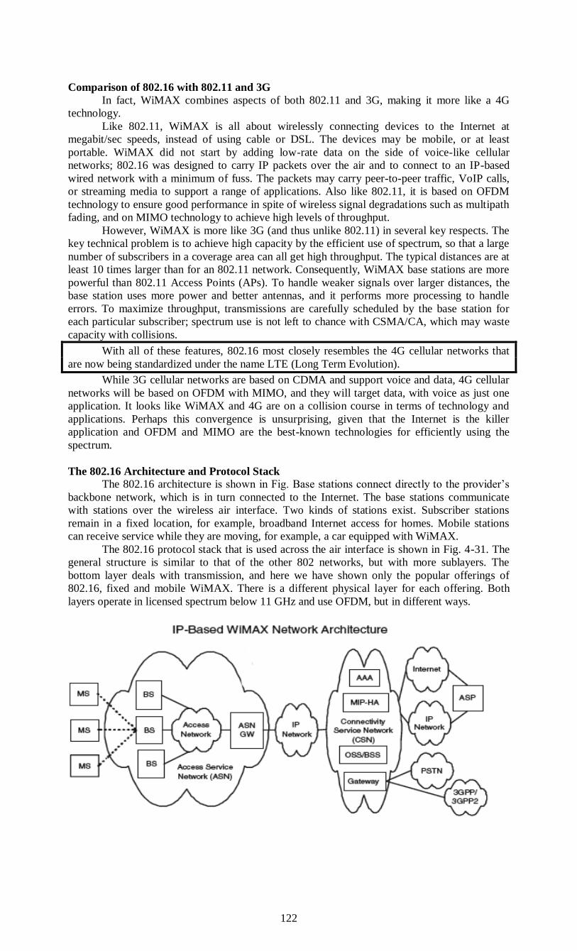
122
Comparison of 802.16 with 802.11 and 3G
In fact, WiMAX combines aspects of both 802.11 and 3G, making it more like a 4G
technology.
Like 802.11, WiMAX is all about wirelessly connecting devices to the Internet at
megabit/sec speeds, instead of using cable or DSL. The devices may be mobile, or at least
portable. WiMAX did not start by adding low-rate data on the side of voice-like cellular
networks; 802.16 was designed to carry IP packets over the air and to connect to an IP-based
wired network with a minimum of fuss. The packets may carry peer-to-peer traffic, VoIP calls,
or streaming media to support a range of applications. Also like 802.11, it is based on OFDM
technology to ensure good performance in spite of wireless signal degradations such as multipath
fading, and on MIMO technology to achieve high levels of throughput.
However, WiMAX is more like 3G (and thus unlike 802.11) in several key respects. The
key technical problem is to achieve high capacity by the efficient use of spectrum, so that a large
number of subscribers in a coverage area can all get high throughput. The typical distances are at
least 10 times larger than for an 802.11 network. Consequently, WiMAX base stations are more
powerful than 802.11 Access Points (APs). To handle weaker signals over larger distances, the
base station uses more power and better antennas, and it performs more processing to handle
errors. To maximize throughput, transmissions are carefully scheduled by the base station for
each particular subscriber; spectrum use is not left to chance with CSMA/CA, which may waste
capacity with collisions.
With all of these features, 802.16 most closely resembles the 4G cellular networks that
are now being standardized under the name LTE (Long Term Evolution).
While 3G cellular networks are based on CDMA and support voice and data, 4G cellular
networks will be based on OFDM with MIMO, and they will target data, with voice as just one
application. It looks like WiMAX and 4G are on a collision course in terms of technology and
applications. Perhaps this convergence is unsurprising, given that the Internet is the killer
application and OFDM and MIMO are the best-known technologies for efficiently using the
spectrum.
The 802.16 Architecture and Protocol Stack
The 802.16 architecture is shown in Fig. Base stations connect directly to the provider’s
backbone network, which is in turn connected to the Internet. The base stations communicate
with stations over the wireless air interface. Two kinds of stations exist. Subscriber stations
remain in a fixed location, for example, broadband Internet access for homes. Mobile stations
can receive service while they are moving, for example, a car equipped with WiMAX.
The 802.16 protocol stack that is used across the air interface is shown in Fig. 4-31. The
general structure is similar to that of the other 802 networks, but with more sublayers. The
bottom layer deals with transmission, and here we have shown only the popular offerings of
802.16, fixed and mobile WiMAX. There is a different physical layer for each offering. Both
layers operate in licensed spectrum below 11 GHz and use OFDM, but in different ways.

123
Above the physical layer, the data link layer consists of three sublayers. The bottom one
deals with privacy and security, which is far more crucial for public outdoor networks than for
private indoor networks. It manages encryption, decryption, and key management.
Next comes the MAC common sublayer part. This part is where the main protocols, such
as channel management, are located. The model here is that the base station completely controls
the system. It can schedule the downlink (i.e., base to subscriber) channels very efficiently and
plays a major role in managing the uplink (i.e., subscriber to base) channels as well. An unusual
feature of this MAC sublayer is that, unlike those of the other 802 protocols, it is completely
connection oriented, in order to provide quality of service guarantees for telephony and
multimedia communication.
The 802.16 Physical Layer
Most WiMAX deployments use licensed spectrum around either 3.5 GHz or 2.5 GHz. As
with 3G, finding available spectrum is a key problem. To help, the 802.16 standard is designed
for flexibility. It allows operation from 2 GHz to 11 GHz. Channels of different sizes are
supported, for example, 3.5 MHz for fixed WiMAX and from 1.25 MHz to 20 MHz for mobile
WiMAX.
Transmissions are sent over these channels with OFDM. Compared to 802.11, the 802.16
OFDM design is optimized to make the most out of licensed spectrum and wide area
transmissions.
The channel is divided into more subcarriers with a longer symbol duration to tolerate
larger wireless signal degradations; WiMAX parameters are around 20 times larger than
comparable 802.11 parameters. For example, in mobile WiMAX there are 512 subcarriers for a
5-MHz channel and the time to send a symbol on each subcarrier is roughly 100 μsec.
Symbols on each subcarrier are sent with QPSK, QAM-16, or QAM-64, modulation
schemes we described in Sec. 2.5.3. When the mobile or subscriber station is near the base
station and the received signal has a high signal-to-noise ratio (SNR), QAM-64 can be used to
send 6 bits per symbol. To reach distant stations with a low SNR, QPSK can be used to deliver 2
bits per symbol.
The designers chose a flexible scheme for dividing the channel between stations, called
OFDMA (Orthogonal Frequency Division Multiple Access).With OFDMA, different sets of
subcarriers can be assigned to different stations, so that more than one station can send or receive
at once. If this were 802.11, all subcarriers would be used by one station to send at any given
moment. The added flexibility in how bandwidth is assigned can increase performance because a
given subcarrier might be faded at one receiver due to multipath effects but clear at another.
Subcarriers can be assigned to the stations that can use them best. As well as having asymmetric
traffic, stations usually alternate between sendingand receiving. This method is called TDD
(Time Division Duplex).
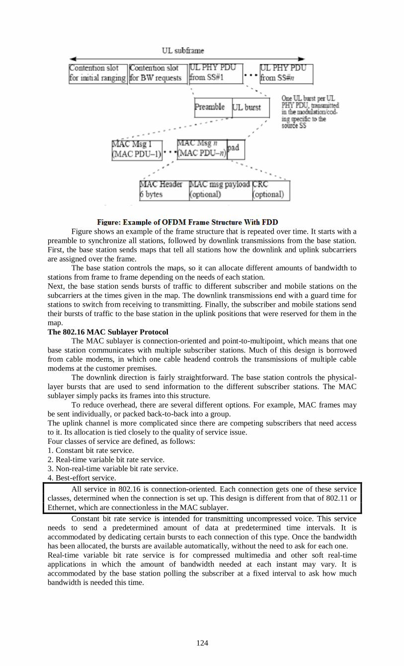
124
Figure shows an example of the frame structure that is repeated over time. It starts with a
preamble to synchronize all stations, followed by downlink transmissions from the base station.
First, the base station sends maps that tell all stations how the downlink and uplink subcarriers
are assigned over the frame.
The base station controls the maps, so it can allocate different amounts of bandwidth to
stations from frame to frame depending on the needs of each station.
Next, the base station sends bursts of traffic to different subscriber and mobile stations on the
subcarriers at the times given in the map. The downlink transmissions end with a guard time for
stations to switch from receiving to transmitting. Finally, the subscriber and mobile stations send
their bursts of traffic to the base station in the uplink positions that were reserved for them in the
map.
The 802.16 MAC Sublayer Protocol
The MAC sublayer is connection-oriented and point-to-multipoint, which means that one
base station communicates with multiple subscriber stations. Much of this design is borrowed
from cable modems, in which one cable headend controls the transmissions of multiple cable
modems at the customer premises.
The downlink direction is fairly straightforward. The base station controls the physical-
layer bursts that are used to send information to the different subscriber stations. The MAC
sublayer simply packs its frames into this structure.
To reduce overhead, there are several different options. For example, MAC frames may
be sent individually, or packed back-to-back into a group.
The uplink channel is more complicated since there are competing subscribers that need access
to it. Its allocation is tied closely to the quality of service issue.
Four classes of service are defined, as follows:
1. Constant bit rate service.
2. Real-time variable bit rate service.
3. Non-real-time variable bit rate service.
4. Best-effort service.
All service in 802.16 is connection-oriented. Each connection gets one of these service
classes, determined when the connection is set up. This design is different from that of 802.11 or
Ethernet, which are connectionless in the MAC sublayer.
Constant bit rate service is intended for transmitting uncompressed voice. This service
needs to send a predetermined amount of data at predetermined time intervals. It is
accommodated by dedicating certain bursts to each connection of this type. Once the bandwidth
has been allocated, the bursts are available automatically, without the need to ask for each one.
Real-time variable bit rate service is for compressed multimedia and other soft real-time
applications in which the amount of bandwidth needed at each instant may vary. It is
accommodated by the base station polling the subscriber at a fixed interval to ask how much
bandwidth is needed this time.

125
BLUETOOTH
Bluetooth is a wireless LAN technology used to connect devices of different functions
such as telephones, computers (laptop or desktop), notebooks, cameras, printers and so on.
Bluetooth project was started by SIG (Special Interest Group) formed by four companies
- IBM, Intel, Nokia and Toshiba for interconnecting computing and communicating
devices using short-range, lower-power, inexpensive wireless radios.
The project was named Bluetooth after the name of Viking king – Harald Blaatand who
unified Denmark and Norway in 10th century.
Nowadays, Bluetooth technology is used for several computer and non computer
application:
1. It is used for providing communication between peripheral devices like wireless mouse or
keyboard with the computer.
2. It is used by modern healthcare devices to send signals to monitors.
3. It is used by modern communicating devices like mobile phone, PDAs, palmtops etc to
transfer data rapidly.
4. It is used for dial up networking. Thus it allows a notebook computer to call via a mobile
phone.
5. It is used for cordless telephoning to connect a handset and its local base station.
6. It also allows hands-free voice comml1nication with headset.
7. It also enables a mobile computer to connect to a fixed LAN.
8. It can also be used for file transfer operations from one mobile phone to another.
Bluetooth devices have a built-in short range radio transmitter. The rate provided is 1Mbps and
uses 2.4 GHz bandwidth.
Bluetooth Architecture
Bluetooth architecture defines two types of networks:
1) Piconet
2) Scattemet
1. Piconet
Piconet is a Bluetooth network that consists of one primary (master) node and seven
active secondary (slave) nodes.
Thus, piconet can have up to eight active nodes (1 master and 7 slaves) or stations within
the distance of 10 meters.
There can be only one primary or master station in each piconet.
The communication between the primary and the secondary can be one-to-one or one-to-
many.

126
All communication is between master and a slave. Salve-slave communication is not
possible.
In addition to seven active slave station, a piconet can have upto 255 parked nodes. These
parked nodes are secondary or slave stations and cannot take part in communication until
it is moved from parked state to active state.
2. Scatternet
Scattemet is formed by combining various piconets.
A slave in one piconet can act as a master or primary in other piconet.
Such a station or node can receive messages from the master in the first piconet and
deliver the message to its slaves in other piconet where it is acting as master. This node is
also called bridge slave.
Thus a station can be a member of two piconets.
A station cannot be a master in two piconets.
Bluetooth Applications
Most network protocols just provide channels between communicating entities and let
application designers figure out what they want to use them for. For example, 802.11 does not
specify whether users should use their notebook computers for reading email, surfing the Web,
or something else. In contrast, the Bluetooth SIG specifies particular applications to be supported
and provides different protocol stacks for each one. At the time of writing, there are 25
applications, which are called profiles. Unfortunately, this approach leads to a very large amount
of complexity. We will omit the complexity here but will briefly look at the profiles to see more
clearly what the Bluetooth SIG is trying to accomplish.
Six of the profiles are for different uses of audio and video. For example, the intercom
profile allows two telephones to connect as walkie-talkies. The headset and hands-free profiles
both provide voice communication between a headset and its base station, as might be used for
hands-free telephony while driving a car.
The human interface device profile is for connecting keyboards and mice to computers.
Other profiles let a mobile phone or other computer receive images from a camera or send
images to a printer. Perhaps of more interest is a profile to use a mobile phone as a remote
control for a (Bluetooth-enabled) TV.
Still other profiles enable networking. The personal area network profile lets Bluetooth
devices form an ad hoc network or remotely access another network, such as an 802.11 LAN, via
an access point. The dial-up networking profile was actually the original motivation for the
whole project. It allows a notebook computer to connect to a mobile phone containing a built-in
modem without using wires.
Profiles for higher-layer information exchange have also been defined. The
synchronization profile is intended for loading data into a mobile phone when it leaves home and
collecting data from it when it returns.
We will skip the rest of the profiles, except to mention that some profiles serve as
building blocks on which the above profiles are built. The generic access profile, on which all of
the other profiles are built, provides a way to establish and maintain secure links (channels)

127
between the master and the slaves. The other generic profiles define the basics of object
exchange and audio and video transport. Utility profiles are used widely for functions such as
emulating a serial line, which is especially useful for many legacy applications.
Bluetooth layers and Protocol Stack
Bluetooth standard has many protocols that are organized into different layers.
The layer structure of Bluetooth does not follow OS1 model, TCP/IP model or any other
known model.
The different layers and Bluetooth protocol architecture.
Radio Layer
The Bluetooth radio layer corresponds to the physical layer of OSI model.
It deals with ratio transmission and modulation.
The radio layer moves data from master to slave or vice versa.
It is a low power system that uses 2.4 GHz ISM band in a range of 10 meters.
This band is divided into 79 channels of 1MHz each. Bluetooth uses the Frequency
Hopping Spread Spectrum (FHSS) method in the physical layer to avoid interference
from other devices or networks.
Bluetooth hops 1600 times per second, i.e. each device changes its modulation frequency
1600 times per second.
In order to change bits into a signal, it uses a version of FSK called GFSK i.e. FSK with
Gaussian bandwidth filtering.
Baseband Layer
Baseband layer is equivalent to the MAC sublayer in LANs.
Bluetooth uses a form of TDMA called TDD-TDMA (time division duplex TDMA).
Master and slave stations communicate with each other using time slots.
The master in each piconet defines the time slot of 625 µsec.
In TDD- TDMA, communication is half duplex in which receiver can send and receive
data but not at the same time.
If the piconet has only no slave; the master uses even numbered slots (0, 2, 4, ...) and the
slave uses odd-numbered slots (1, 3, 5, .... ). Both master and slave communicate in half
duplex mode. In slot 0, master sends & secondary receives; in slot 1, secondary sends and
primary receives.
If piconet has more than one slave, the master uses even numbered slots. The slave sends
in the next odd-numbered slot if the packet in the previous slot was addressed to it.
In Baseband layer, two types of links can be created between a master and slave. These
are:
1. Asynchronous Connection-less (ACL)
128
It is used for packet switched data that is available at irregular intervals.
ACL delivers traffic on a best effort basis. Frames can be lost & may have to be
retransmitted.
A slave can have only one ACL link to its master.
Thus ACL link is used where correct delivery is preferred over fast delivery.
The ACL can achieve a maximum data rate of 721 kbps by using one, three or more slots.
2. Synchronous Connection Oriented (SCO)
sco is used for real time data such as sound. It is used where fast delivery is preferred
over accurate delivery.
In an sco link, a physical link is created between the master and slave by reserving
specific slots at regular intervals.
Damaged packet; are not retransmitted over sco links.
A slave can have three sco links with the master and can send data at 64 Kbps.
Logical Link, Control Adaptation Protocol Layer (L2CAP)
The logical unit link control adaptation protocol is equivalent to logical link control
sublayer of LAN.
The ACL link uses L2CAP for data exchange but sco channel does not use it.
The various function of L2CAP is:
1. Segmentation and reassembly
L2CAP receives the packets of upto 64 KB from upper layers and divides them into
frames for transmission.
It adds extra information to define the location of frame in the original packet.
The L2CAP reassembles the frame into packets again at the destination.
2. Multiplexing
L2CAP performs multiplexing at sender side and demultiplexing at receiver side.
At the sender site, it accepts data from one of the upper layer protocols frames them and
deliver them to the Baseband layer.
At the receiver site, it accepts a frame from the baseband layer, extracts the data, and
delivers them to the appropriate protocol1ayer.
3. Quality of Service (QOS)
L2CAP handles quality of service requirements, both when links are established and
during normal operation.
It also enables the devices to negotiate the maximum payload size during connection
establishment.
Bluetooth Frame Format
The various fields of blue tooth frame format are:

129
1. Access Code: It is 72 bit field that contains synchronization bits. It identifies the master.
2. Header: This is 54-bit field. It contain 18 bit pattern that is repeated for 3 time.
The header field contains following subfields:
(i) Address: This 3 bit field can define upto seven slaves (1 to 7). If the address is zero, it is used
for broadcast communication from primary to all secondaries.
(ii)Type: This 4 bit field identifies the type of data coming from upper layers.
(iii) F: This flow bit is used for flow control. When set to 1, it means the device is unable to
receive more frames.
(iv) A: This bit is used for acknowledgement.
(v) S: This bit contains a sequence number of the frame to detect retransmission. As stop and
wait protocol is used, one bit is sufficient.
(vi) Checksum: This 8 bit field contains checksum to detect errors in header.
3. Data: This field can be 0 to 2744 bits long. It contains data or control information coming
from upper layers.
RFID
RFID technology takes many forms, used in smartcards, implants for pets, passports,
library books, and more. The form that we will look at was developed in the quest for an EPC
(Electronic Product Code) that started with the Auto-ID Center at the Massachusetts Institute
of Technology in 1999. An EPC is a replacement for a barcode that can carry a larger amount of
information and is electronically readable over distances up to 10 m, even when it is not visible.
It is different technology than, for example, the RFID used in passports,which must be placed
quite close to a reader to perform a transaction. The ability to communicate over a distance
makes EPCs more relevant to our studies.
EPCglobal was formed in 2003 to commercialize the RFID technology developed by the
Auto-ID Center. The effort got a boost in 2005 when Walmart required its top 100 suppliers to
label all shipments with RFID tags. Widespread deployment has been hampered by the difficulty
of competing with cheap printed barcodes, but new uses, such as in drivers licenses, are now
growing. We will describe the second generation of this technology, which is informally called
EPC Gen 2 (EPCglobal, 2008).
130
EPC Gen 2 Architecture
It has two key components: tags and readers. RFID tags are small, inexpensive devices
that have a unique 96-bit EPC identifier and a small amount of memory that can be read and
written by the RFID reader. The memory might be used to record the location history of an item,
for example, as it moves through the supply chain.
The readers are the intelligence in the system, analogous to base stations and access
points in cellular and WiFi networks. Readers are much more powerful than tags. They have
their own power sources, often have multiple antennas, and are in charge of when tags send and
receive messages. As there will commonly be multiple tags within the reading range, the readers
must solve the multiple access problems. There may be multiple readers that can contend with
each other in the same area, too.
The main job of the reader is to inventory the tags in the neighborhood, that is, to
discover the identifiers of the nearby tags. The inventory is accomplished with the physical layer
protocol and the tag- identification protocol that are outlined in the following sections.

131
Unit III
QUESTIONS
SECTION A
1. The ------------- layer is layer 2 in the Open Systems Interconnect (OSI) model for a set
of telecommunication protocols.
2. The two sub-layers of data link layer are----------, ------------------.
3. What is redundancy?
4. ---------, ----------, ---------- techniques are used to detect the errors.
5. What is check sum?
6. --------------- is an error control method for data transmission that makes use of error-
detection codes and timeouts to achieve reliable data transmission.
7. The elementary data link protocols are -----------, -----------, and ---------.
8. The technique of temporarily delaying outgoing acknowledgements so that they can
be hooked onto the next outgoing data frame is known as --------------.
9. What are the types of Sliding window protocol?
10. What is ALOHA?
11. The ----------- uses two clocks at every node, a virtual clock (vc) and a real clock (rc)
which tells "real time".
12. ---------, ---------, ---------- are the access modes of CSMA.
13. Expand CSMA and CDMA.
14. --------- is a passive, contention-based broadcast technology that uses baseband
signaling.
15. ---------- is a wireless LAN technology used to connect devices of different functions
such as telephones, computers (laptop or desktop), notebooks, cameras, printers and
so on.
SECTION B
1. Explain the technique of CRC.
2. Discuss about Error Correction methods.
3. What are the types of elementary data link protocols? Explain.
4. Discuss about Go-Back-N ARQ.
5. Explain i) Pure ALOHA ii) Slotted ALOHA.
6. Discuss about a simplex stop and wait protocols in Elementary Data Link Protocols.
7. Explain piggy backing with sliding window protocols.
8. Compare 802.11 with 802.16.
9. Explain in detail about Simplex protocol for a Noisy Channel.
10. Discuss about the current trends in Wireless technology.
SECTION C
1. Explain the Error Correction techniques in detail.
2. Explain the Error Detection techniques in detail.
3. Explain Elementary data link protocols in detail
4. Explain about the channel allocation problem.
5. What is Piggy backing? Explain Sliding Window protocols in detail.
6. What are the protocols are used in MAC Sub-layer? Explain in detail.
7. Explain 1). Ethernet cabling 2). Gigabit Ethernet
8. Explain about Broadband wireless.
9. Explain in detail about Bluetooth architecture.
10. Explain 1). L2CAP. 2).Baseband layer in Bluetooth.
132
UNIT-IV: NETWORK LAYER: Routing algorithms – Congestion Control Algorithms.
TRANSPORT LAYER: Elements of Transport Protocols – Internet Transport Protocols: TCP.
NETWORK LAYER
The network layer is responsible for packet forwarding including routing through
intermediate routers, whereas the data link layer is responsible for media access control,
flow control and error checking.
The network layer provides the functional and procedural means of transferring variable-
length data sequences from a source to a destination host via one or more networks, while
maintaining the quality of service functions.
Functions of the network layer include:
Connection model: connectionless communication
For example, IP is connectionless, in that a datagram can travel from a sender to a
recipient without the recipient having to send an acknowledgement. Connection-oriented
protocols exist at other, higher layers of the OSI model.
Host addressing
Every host in the network must have a unique address that determines where it is. This
address is normally assigned from a hierarchical system. For example, you can be "Fred
Murphy" to people in your house, "Fred Murphy, 1 Main Street" to Dubliners, or "Fred Murphy,
1 Main Street, Dublin" to people in Ireland, or "Fred Murphy, 1 Main Street, Dublin, Ireland" to
people anywhere in the world. On the Internet, addresses are known as Internet Protocol (IP)
addresses.
Message forwarding
Since many networks are partitioned into subnetworks and connect to other networks for
wide-area communications, networks use specialized hosts, called gateways or routers, to
forward packets between networks. This is also of interest to mobile applications, where a user
may move from one location to another, and it must be arranged that his messages follow him.
Version 4 of the Internet Protocol (IPv4) was not designed with this feature in mind, although
mobility extensions exist. IPv6 has a better designed solution.
Within the service layering semantics of the OSI network architecture, the network layer
responds to service requests from the transport layer and issues service requests to the data link
layer.
ROUTING ALGORITHMS
Routing is the process of selecting paths in a network along which to send data on
physical traffic. In different network operating system the network layer perform the
function of protocol routing.
A system that performs this function is called an IP router.
There are two types of routing algorithm :
Static
Dynamic
This type of device attaches to two or more physical networks and forwards packets
between the networks. When sending data to a remote destination, a host passes packet to a local
router.
The router forwards the packet toward the final destination. They travel from one router
to another until they reach a router connected to the destination’s LAN segment. Each router
along the end-to-end path selects the next hop device used to reach the destination. The next hop
represents the next device along the path to reach the destination.
It is located on a physical network connected to this intermediate system. Because this
physical network differs from the one on which the system originally received the datagram, the
intermediate host has forwarded (that is, routed) the packets from one physical network to
another.
There are two types of routing algorithm:
Static
Dynamic

133
Static Routing: Static routing uses preprogrammed definitions representing paths through the
network. Static routing is manually performed by the network administrator. The administrator is
responsible for discovering and propagating routes through the network.
These definitions are manually programmed in every routing device in the environment.
After a device has been configured, it simply forwards packets out the predetermined ports.
There is no communication between routers regarding the current topology of the network. In
small networks with minimal redundancy, this process is relatively simple to administer.
Dynamic Routing: Dynamic routing algorithms allow routers to automatically discover and
maintain awareness of the paths through the network. This automatic discovery can use a number
of currently available dynamic routing protocols.
Following are the routing algorithms for networks:
1 Shortest Path Routing
2 Flooding
3 Distance Vector Routing
4 Link State Routing
5 Path Vector Routing
6 Hybrid Routing
1). Shortest Path Routing
The shortest path concept includes definition of the way of measuring path length.
Deferent metrics like number of hops, geographical distance, the mean queuing and transmission
delay of router can be used. In the most general case, the labels on the arcs could be computed as
a function of the distance, bandwidth, average traffic, communication cost, mean queue length,
measured delay, and other factors.
There are several algorithms for computing shortest path between two nodes of a graph.
One of them is Dijkstra.
For a given source vertex (node) in the graph, the algorithm finds the path with lowest cost (i.e.
the shortest path) between that vertex and every other vertex. It can also be used for finding costs
of shortest paths from a single vertex to a single destination vertex by stopping the algorithm
once the shortest path to the destination vertex has been determined.
For example, if the vertices of the graph represent cities and edge path costs represent
driving distances between pairs of cities connected by a direct road, Dijkstra's algorithm can be
used to find the shortest route between one city and all other cities. As a result, the shortest path
algorithm is widely used in network routing protocols, most notably IS-IS and OSPF (Open
Shortest Path First).
Dijkstra's original algorithm does not use a min-priority queue and runs in time
(where is the number of vertices). The idea of this algorithm is also given in
(Leyzorek et al. 1957). The implementation based on a min-priority queue implemented by a
Fibonacci heap and running in (where is the number of edges) is
due to (Fredman & Tarjan 1984). This is asymptotically the fastest known single-source shortest-
path algorithm for arbitrary directed graphs with unbounded non-negative weights.
2). Flooding
That is another static algorithm, in witch every incoming packet is sent out on every
outgoing line except the one it arrived on. Flooding generates infinite number of duplicate
packets unless some measures are taken to damp the process.
One such measure is to have a hop counter in the header of each packet, which is
decremented at each hop, with the packet being discarded when the counter reaches zero. Ideally,
the hop counter is initialized to the length of the path from source to destination. If the sender
does not no the path length, it can initialize the counter to the worst case, the full diameter of the
subnet.
An alternative technique is to keep track of which packets have been flooded, to avoid
sending then out a second time. To achieve this goal the source router put a sequence number in
each packet it receives from its hosts. Then each router needs a list per source router telling
which sequence numbers originating at that source have already been seen. Any incoming packet
that is on the list is not flooded. To prevent list form growing, each list should be augmented by a
counter, k, meaning that all sequence numbers through k have been seen.

134
A variation of flooding named selective flooding is slightly more practical. In this
algorithm the routers do not send every incoming packet out on every line, but only on those
going approximately in the right direction.(there is usually little point in sending a westbound
packet on an eastbound line unless the topology is extremely peculiar).
Flooding algorithms are rarely used, mostly with distributed systems or systems with
tremendous robustness requirements at any instance.
3). Distance Vector Routing
The distance-vector routing Protocol is a type of algorithm used by routing protocols to
discover routes on an interconnected network. The primary distance-vector routing protocol
algorithm is the Bellman-Ford algorithm. Another type of routing protocol algorithm is the link-
state approach.
Routing protocols that use distance-vector routing protocols include RIP (Routing
Information Protocol), Cisco's IGRP (Internet Gateway Routing Protocol), and Apple's
RTMP (Routing Table Maintenance Protocol). The most common link-state routing protocol
is OSPF (Open Shortest Path First). Dynamic routing, as opposed to static (manually entered)
routing, requires routing protocol algorithms.
Dynamic routing protocols assist in the automatic creation of routing tables. Network
topologies are subject to change at any time. A link may fail unexpectedly, or a new link may be
added. A dynamic routing protocol must discover these changes, automatically adjust its routing
tables, and inform other routers of the changes.
The process of rebuilding the routing tables based on new information is called
convergence. Distance-vector routing refers to a method for exchanging route information. A
router will advertise a route as a vector of direction and distance.
Direction refers to a port that leads to the next router along the path to the destination,
and distance is a metric that indicates the number of hops to the destination, although it may also
be an arbitrary value that gives one route precedence over another. Inter network routers
exchange this vector information and build route lookup tables from it. Distance vector protocols
are RIP, Interior Gateway Routing Protocol (IGPR).
Algorithm where each router exchanges its routing table with each of its neighbors. Each
router will then merge the received routing tables with its own table, and then transmit the
merged table to its neighbors. This occurs dynamically after a fixed time interval by default, thus
requiring significant link overhead.
135
There are problems, however, such as:
If exchanging data among routers every 90 seconds for example, it takes 90 x 10 seconds
that a router detects a problem in router 10, routers ahead and the route cannot be
changed during this period.
Traffic increases since routing information is continually exchanged.
There is a limit to the maximum amount of routing information (15 for RIP), and routing
is not possible on networks where the number of hops exceeds this maximum.
Cost data is only the number of hops, and so selecting the best path is difficult.
However, routing processing is simple, and it is used in small-scale networks in which
the points mentioned above are not a problem.
The distance vector routing algorithm is sometimes called by other names including
Bellman-Ford or Ford-Fulkerson. It was the original ARPANET routing algorithm and was
also used in the Internet under the name RIP and in early versions of DECnet and Novell’s IPX.
AppleTalk & CISCO routers use improved distance vector protocols.
In that algorithm each router maintains a routing table indexed by and containing one
entry for each router in the subnet. This entry contains two parts: the preferred outgoing line to
use for that destination and an estimate of the time or distance to that destination. The metric
used might be number of hops, time delay in milliseconds, total number of packets queued along
the path or something similar.
The router is assumed to know the “distance” to each of its neighbors. In the hops metric
the distance is one hop, for queue length metrics the router examines each queue, for the delay
metric the route can measure it directly with special ECHO packets that the receiver just
timestamps and sends back as fast as it can.
Distance vector routing works in theory, but has a serious drawback in practice: although
it converges to the correct answer, it may be done slowly.
Good news propagates at linear time through the subnet, while bad ones have the count-
to-infinity problem: no router ever has a value more then one higher than the minimum of all its
neighbors. Gradually, all the routers work their way up to infinity, but the number of exchanges
required depends on the numerical value used for infinity. One of the solutions to this problem is
split horizon algorithm that defines the distance to the X router is reported as infinity on the line
that packets for X are sent on. Under that behaviour bad news propagate also at linear speed
through the subnet.
4). Link State Routing
Algorithm where each router in the network learns the network topology then creates a
routing table based on this topology. Each router will send information of its links (Link-State) to
its neighbour who will In turn propagate the information to its neighbours, etc. This occurs until
all routers have built a topology of the network. Each router will then prune the topology, with
itself as the root, choosing the least-cost-path to each router, then build a routing table based on
the pruned topology.
The idea behind link state routing is simple and can be stated as five parts. Each router must:
1) Discover its neighbours and learn their network addresses.
2) Measure the delay or cost to each of its neighbours.
3) Construct a packet telling to all it has just learned.
4) Send the packet to all other routers.

136
5) Compute the shortest path to every other router.
In effect, the complete topology and all delays re experimentally measured and distributed to
every router. Then Dijkstra’s algorithm can be used to find the shortest path to every other
router.
Determining the neighbors of each node[edit]First, each node needs to determine what
other ports it is connected to, over fully working links; it does this using a reachability protocol
which it runs periodically and separately with each of its directly connected neighbors.
Distributing the information for the map[edit]Next, each node periodically (and in case of
connectivity changes) sends a short message, the link-state advertisement, which:
Identifies the node which is producing it.
Identifies all the other nodes (either routers or networks) to which it is directly connected.
Includes a sequence number, which increases every time the source node makes up a new
version of the message.
This message is then flooded throughout the network. As a necessary precursor, each
node in the network remembers, for every other node in the network, the sequence
number of the last link-state message which it received from that node.
Starting with the node which originally produced the message, it sends a copy to all of its
neighbors. When a link-state advertisement is received at a node, the node looks up the sequence
number it has stored for the source of that link-state message. If this message is newer (i.e., has a
higher sequence number), it is saved, and a copy is sent in turn to each of that node's neighbors.
This procedure rapidly gets a copy of the latest version of each node's link-state advertisement to
every node in the network.
a). Learning about the Neighbors
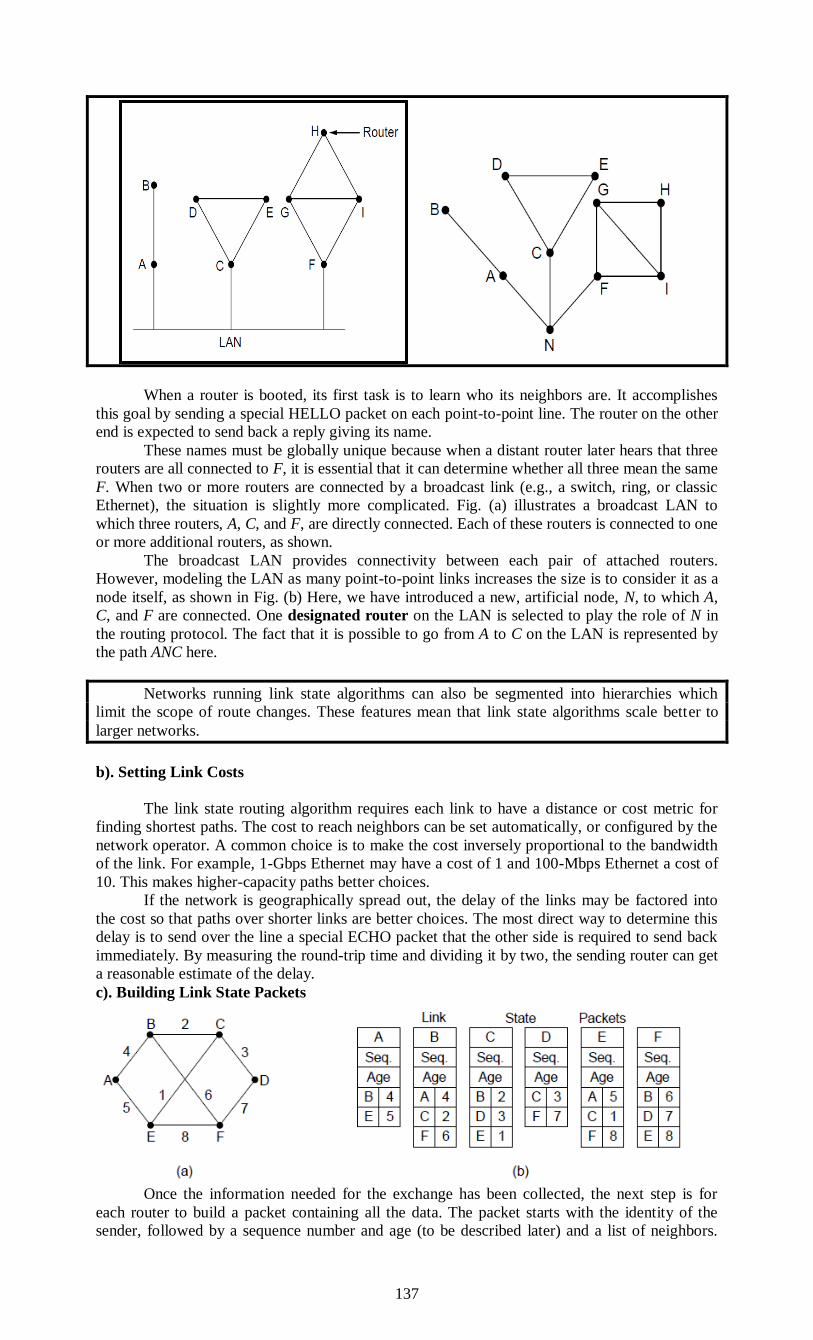
137
When a router is booted, its first task is to learn who its neighbors are. It accomplishes
this goal by sending a special HELLO packet on each point-to-point line. The router on the other
end is expected to send back a reply giving its name.
These names must be globally unique because when a distant router later hears that three
routers are all connected to F, it is essential that it can determine whether all three mean the same
F. When two or more routers are connected by a broadcast link (e.g., a switch, ring, or classic
Ethernet), the situation is slightly more complicated. Fig. (a) illustrates a broadcast LAN to
which three routers, A, C, and F, are directly connected. Each of these routers is connected to one
or more additional routers, as shown.
The broadcast LAN provides connectivity between each pair of attached routers.
However, modeling the LAN as many point-to-point links increases the size is to consider it as a
node itself, as shown in Fig. (b) Here, we have introduced a new, artificial node, N, to which A,
C, and F are connected. One designated router on the LAN is selected to play the role of N in
the routing protocol. The fact that it is possible to go from A to C on the LAN is represented by
the path ANC here.
Networks running link state algorithms can also be segmented into hierarchies which
limit the scope of route changes. These features mean that link state algorithms scale better to
larger networks.
b). Setting Link Costs
The link state routing algorithm requires each link to have a distance or cost metric for
finding shortest paths. The cost to reach neighbors can be set automatically, or configured by the
network operator. A common choice is to make the cost inversely proportional to the bandwidth
of the link. For example, 1-Gbps Ethernet may have a cost of 1 and 100-Mbps Ethernet a cost of
10. This makes higher-capacity paths better choices.
If the network is geographically spread out, the delay of the links may be factored into
the cost so that paths over shorter links are better choices. The most direct way to determine this
delay is to send over the line a special ECHO packet that the other side is required to send back
immediately. By measuring the round-trip time and dividing it by two, the sending router can get
a reasonable estimate of the delay.
c). Building Link State Packets
Once the information needed for the exchange has been collected, the next step is for
each router to build a packet containing all the data. The packet starts with the identity of the
sender, followed by a sequence number and age (to be described later) and a list of neighbors.

138
The cost to each neighbor is also given. An example network is presented in Fig. (a) with costs
shown as labels on the lines. The corresponding link state packets for all six routers are shown in
Fig. (b).
Building the link state packets is easy. The hard part is determining when to build them.
One possibility is to build them periodically, that is, at regular intervals. Another possibility is to
build them when some significant event occurs, such as a line or neighbor going down or coming
back up again or changing its properties appreciably.
d). Distributing the Link State Packets
The trickiest part of the algorithm is distributing the link state packets. All of the routers
must get all of the link state packets quickly and reliably. If different routers are using different
versions of the topology, the routes they compute can have inconsistencies such as loops,
unreachable machines, and other problems.
First, we will describe the basic distribution algorithm. After that we will give some
refinements. The fundamental idea is to use flooding to distribute the link state packets to all
routers. To keep the flood in check, each packet contains a sequence number that is incremented
for each new packet sent. Routers keep track of all the (source router, sequence) pairs they see.
When a new link state packet comes in, it is checked against the list of packets already seen. If it
is new, it is forwarded on all lines except the one it arrived on. If it is a duplicate, it is discarded.
If a packet with a sequence number lower than the highest one seen so far ever arrives, it is
rejected as being obsolete as the router has more recent data.
This algorithm has a few problems, but they are manageable. First, if the sequence
numbers wrap around, onfusion will reign. The solution here is to use a 32-bit sequence number.
With one link state packet per second, it would take 137 years to wrap around, so this possibility
can be ignored.
Second, if a router ever crashes, it will lose track of its sequence number. If it starts again
at 0, the next packet it sends will be rejected as a duplicate.
Third, if a sequence number is ever corrupted and 65,540 is received instead of 4 (a 1-bit
error), packets 5 through 65,540 will be rejected as obsolete, since the current sequence number
will be thought to be 65,540.
The solution to all these problems is to include the age of each packet after the sequence
number and decrement it once per second.
When the age hits zero, the information from that router is discarded. Normally, a new
packet comes in, say, every 10 sec, so router information only times out when a router is down
(or six consecutive packets have been lost, an unlikely event). The Age field is also decremented
by each router during the initial flooding process, to make sure no packet can get lost and live for
an indefinite period of time (a packet whose age is zero is discarded).
In the above Fig., the link state packet from A arrives directly, so it must be sent to C and
F and acknowledged to A, as indicated by the flag bits. Similarly, the packet from F has to be
forwarded to A and C and acknowledged to F.
However, the situation with the third packet, from E, is different. It arrives twice, once
via EAB and once via EFB. Consequently, it has to be sent only to C but must be acknowledged
to both A and F, as indicated by the bits.
If a duplicate arrives while the original is still in the buffer, bits have to be changed. For
example, if a copy of C’s state arrives from F before the fourth entry in the table has been
forwarded, the six bits will be changed to 100011 to indicate that the packet must be
acknowledged to F but not sent there.
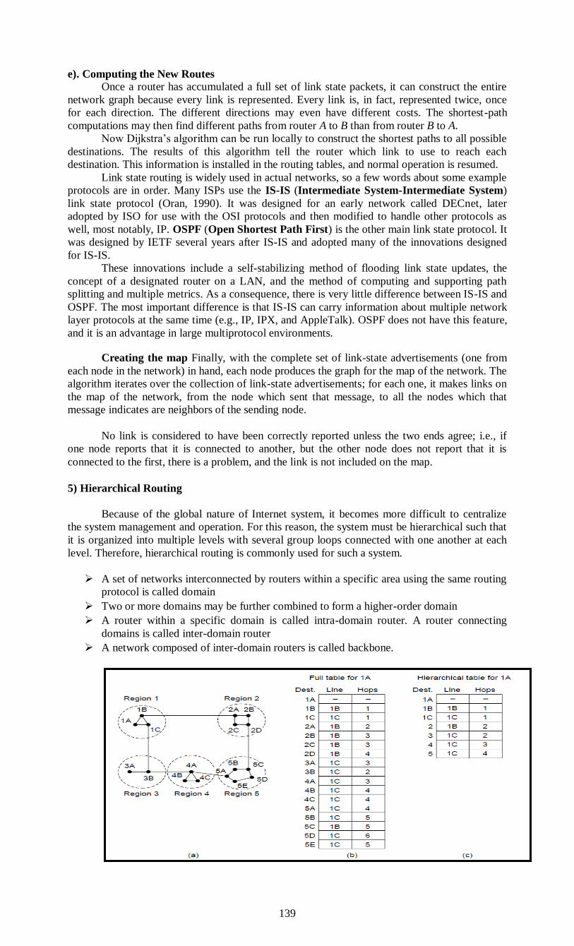
139
e). Computing the New Routes
Once a router has accumulated a full set of link state packets, it can construct the entire
network graph because every link is represented. Every link is, in fact, represented twice, once
for each direction. The different directions may even have different costs. The shortest-path
computations may then find different paths from router A to B than from router B to A.
Now Dijkstra’s algorithm can be run locally to construct the shortest paths to all possible
destinations. The results of this algorithm tell the router which link to use to reach each
destination. This information is installed in the routing tables, and normal operation is resumed.
Link state routing is widely used in actual networks, so a few words about some example
protocols are in order. Many ISPs use the IS-IS (Intermediate System-Intermediate System)
link state protocol (Oran, 1990). It was designed for an early network called DECnet, later
adopted by ISO for use with the OSI protocols and then modified to handle other protocols as
well, most notably, IP. OSPF (Open Shortest Path First) is the other main link state protocol. It
was designed by IETF several years after IS-IS and adopted many of the innovations designed
for IS-IS.
These innovations include a self-stabilizing method of flooding link state updates, the
concept of a designated router on a LAN, and the method of computing and supporting path
splitting and multiple metrics. As a consequence, there is very little difference between IS-IS and
OSPF. The most important difference is that IS-IS can carry information about multiple network
layer protocols at the same time (e.g., IP, IPX, and AppleTalk). OSPF does not have this feature,
and it is an advantage in large multiprotocol environments.
Creating the map Finally, with the complete set of link-state advertisements (one from
each node in the network) in hand, each node produces the graph for the map of the network. The
algorithm iterates over the collection of link-state advertisements; for each one, it makes links on
the map of the network, from the node which sent that message, to all the nodes which that
message indicates are neighbors of the sending node.
No link is considered to have been correctly reported unless the two ends agree; i.e., if
one node reports that it is connected to another, but the other node does not report that it is
connected to the first, there is a problem, and the link is not included on the map.
5) Hierarchical Routing
Because of the global nature of Internet system, it becomes more difficult to centralize
the system management and operation. For this reason, the system must be hierarchical such that
it is organized into multiple levels with several group loops connected with one another at each
level. Therefore, hierarchical routing is commonly used for such a system.
A set of networks interconnected by routers within a specific area using the same routing
protocol is called domain
Two or more domains may be further combined to form a higher-order domain
A router within a specific domain is called intra-domain router. A router connecting
domains is called inter-domain router
A network composed of inter-domain routers is called backbone.

140
Each domain, which is also called operation domain, is a point where the system
operation is divided into plural organizations in charge of operation. Domains are determined
according to the territory occupied by each organization.
Routing protocol in such an Internet system can be broadly divided into two types:
1.Intra-domain routing
2.Inter-domain routing.
Each of these protocols is hierarchically organized. For communication within a domain,
only the former routing is used. However, both of them are used for communication between two
or more domains.
In the following pages, we will look at description of Routing information Protocol
(RIP), Open Shortest Path First (OSPF), and IS-IS, that are intra-domain protocols. RIP and
OSPF will be covered later in detail.
6) Broadcast Routing
For some applications, hosts need to send messages to many or all other hosts. Broadcast
routing is used for that purpose. Some deferent methods where proposed for doing that.
The source should send the packet to all the necessary destinations. One of the problems of this
method is that the source has to have the complete list of destinations. Flooding routing. As it was discussed before the problem of that method is generating duplicate
packets.
Multidestination routing. In that method each packet includes list or a bitmap indicating desired destinations. When a packet arrives router checks all the destinations to determine the set of output
lines that will be needed, generates a new copy of the packet for each output line to be used and
includes in each packet only those destinations that are to use the line. In effect, the destination set is
partitioned between the lines. After a sufficient number of hops, each packet will carry only one destination and can be treated as a normal packet.
This routing method makes use of spanning tree of the subnet. If each router knows which of its
lines belong to the panning tree, it can copy an incoming broadcast packet onto all the spanning tree lines except the one it arrived on. Problem: each router has to know the spanning tree.
Reverse path-forwarding algorithm at the arrival of the packet checks if the line that packet arrived
on is the same one through which the packets are send to the source, if yes it sends it through all other lines, otherwise discards it.
7). Multicast Routing
Sending messages to well-defined groups that are numerically large in size, but small
compared to the network as a whole is called multicasting. To do multicasting, group
management is required, but that is not concern of routers. What is of concern is that when a
process joins a group, it informs its host of this fact. It is important that routers know which of
their hosts belong to which group. Either hosts must inform their routers about changes in group
membership, or routers must query their hosts periodically.
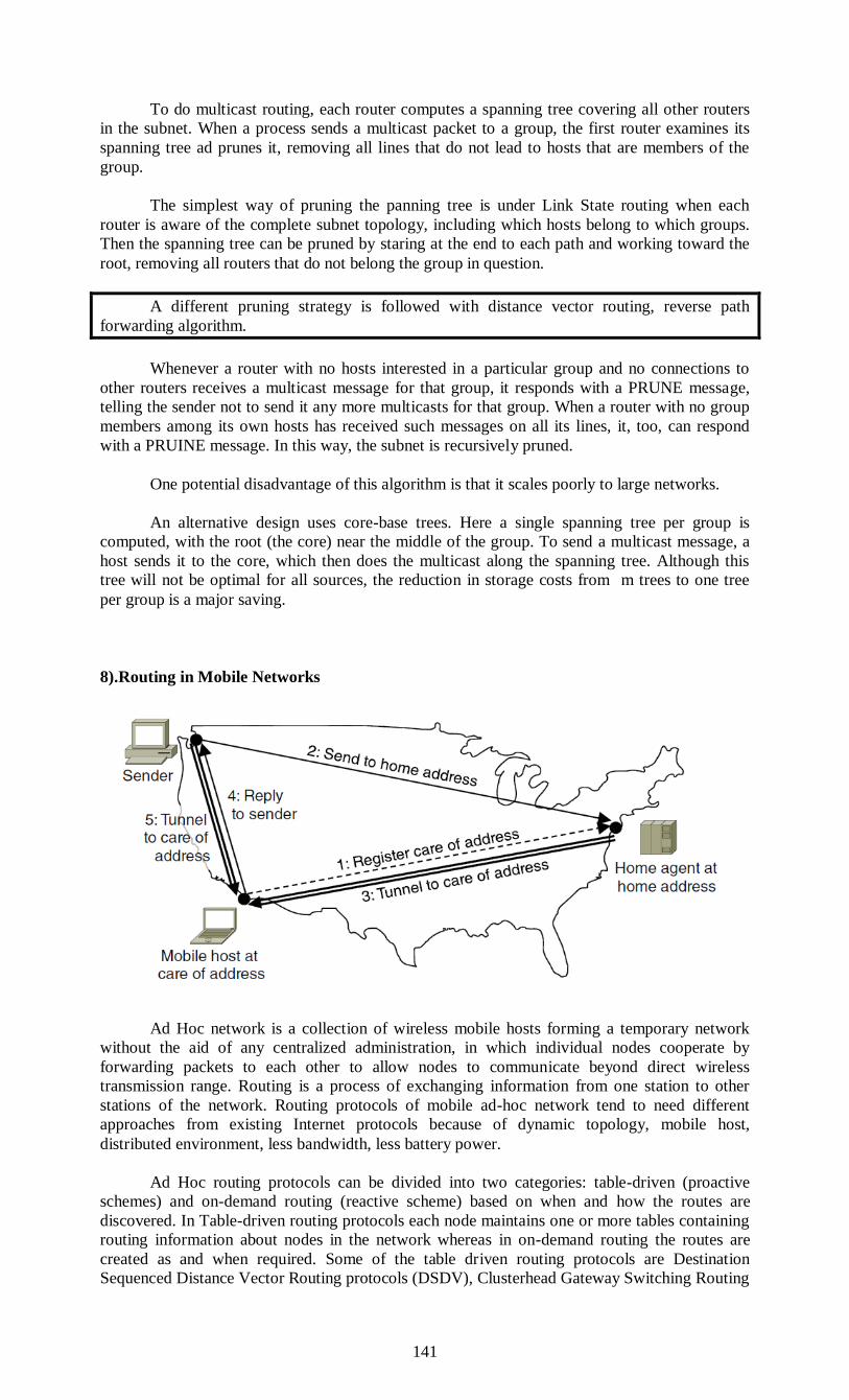
141
To do multicast routing, each router computes a spanning tree covering all other routers
in the subnet. When a process sends a multicast packet to a group, the first router examines its
spanning tree ad prunes it, removing all lines that do not lead to hosts that are members of the
group.
The simplest way of pruning the panning tree is under Link State routing when each
router is aware of the complete subnet topology, including which hosts belong to which groups.
Then the spanning tree can be pruned by staring at the end to each path and working toward the
root, removing all routers that do not belong the group in question.
A different pruning strategy is followed with distance vector routing, reverse path
forwarding algorithm.
Whenever a router with no hosts interested in a particular group and no connections to
other routers receives a multicast message for that group, it responds with a PRUNE message,
telling the sender not to send it any more multicasts for that group. When a router with no group
members among its own hosts has received such messages on all its lines, it, too, can respond
with a PRUINE message. In this way, the subnet is recursively pruned.
One potential disadvantage of this algorithm is that it scales poorly to large networks.
An alternative design uses core-base trees. Here a single spanning tree per group is
computed, with the root (the core) near the middle of the group. To send a multicast message, a
host sends it to the core, which then does the multicast along the spanning tree. Although this
tree will not be optimal for all sources, the reduction in storage costs from m trees to one tree
per group is a major saving.
8).Routing in Mobile Networks
Ad Hoc network is a collection of wireless mobile hosts forming a temporary network
without the aid of any centralized administration, in which individual nodes cooperate by
forwarding packets to each other to allow nodes to communicate beyond direct wireless
transmission range. Routing is a process of exchanging information from one station to other
stations of the network. Routing protocols of mobile ad-hoc network tend to need different
approaches from existing Internet protocols because of dynamic topology, mobile host,
distributed environment, less bandwidth, less battery power.
Ad Hoc routing protocols can be divided into two categories: table-driven (proactive
schemes) and on-demand routing (reactive scheme) based on when and how the routes are
discovered. In Table-driven routing protocols each node maintains one or more tables containing
routing information about nodes in the network whereas in on-demand routing the routes are
created as and when required. Some of the table driven routing protocols are Destination
Sequenced Distance Vector Routing protocols (DSDV), Clusterhead Gateway Switching Routing

142
Protocol (CGSR), Hierarchical State Routing (HSR), and Wireless Routing Protocol (WRP) etc.
The on-demand routing protocols are Ad Hoc On-Demand Distance Vector Routing (AODV),
Dynamic Source Routing (DSR), and Temporally Ordered Routing Algorithm (TORA). There
are many others routing protocols available. Zone Routing Protocol (ZRP) is the hybrid routing
protocol.
Through the last years more and more people purchase portable computer under natural
assumption that they can be used all over the world. These mobile hosts introduce new
complication: to route a packet to a mobile host the network first has to find it. Generally that
requirement is implemented through creation of two new issues in LAN foreign agent and home
agent.
Each time any mobile host connects to the network it collects a foreign agent packet or
generates a request for foreign agent, as a result they establish connection between them and the
mobile host supplies the foreign agent with it’s home & some security information.
After that the foreign agent contacts the mobile host’s home agent and delivers the
information about the mobile host.
Subsequently the home agent examines the received information and if it authorizes the
security information of mobile host it allows the foreign agent to proceed. As the result the
foreign agent enters the mobile host into it’s routing table.
When the packet for the mobile host arrive its home agent it encapsulates it and redirects
to the foreign agent where the mobile host is hosting. Then it returns encapsulation data to the
router that sent the packet so that all next packet would be directly sent to correspondent router
(foreign agent).
CONGESTION CONTROL ALGORITHMS
Both transport and network layers share responsibility of handling congestion.
Network layer is directly affected by Congestion.
Incoming packets from multiple inputs need to go to same output line; queue builds up
If insufficient memory, packets lost Adding memory helps to some point Even with ∞
memory, congestion gets worse when,
1. Delayed packets timeout,
2. Retransmitted duplicates increase load
It is practical to divide Congestion Control Algorithms in two main classes. This is either
on host’s side establishing end-to-end Congestion Control called Host Centric or on router’s side
affecting transferred data packets called Router Centric.
A situation is called congestion if performance degrades in a subnet because of too many
data packets in present, i.e. traffic load temporarily exceeds the offered resources.
The number of packets delivered is proportional to the number of packets send. But if
traffic increases too much, routers are no longer able to handle all the traffic and packets will get
lost. With further growing traffic this subnet will collapse and no more packets are delivered.

143
As traffic increases too far, the routers are no longer able to cope and they begin losing
packets. This tends to make matters worse. At very high trafffic, performance collapses
completely and almost no packets are delivered.
Figure: When too much traffic is offered, congestion sets in and performance degrades
sharply.
Congestion can be brought on by several factors. If all of a sudden, streams of packets
begin arriving on three or four input lines and all need the same output line, a queue will build
up. If there is insufficient memory to hold all of them, packets will be lost.
Adding more memory may help up to a point, but Nagle (1987) discovered that if routers have an
infinite amount of memory, congestion gets worse, not better, because by the time packets get to
the front of the queue, they have already timed out (repeatedly) and duplicates have been sent.
All these packets will be dutifully forwarded to the next router, increasing the load all the
way to the destination. Flow control, in contrast, relates to the point-to-point traffic between a
given sender and a given receiver.
Its job is to make sure that a fast sender cannot continually transmit data faster than the
receiver is able to absorb it. Flow control frequently involves some direct feedback from the
receiver to the sender to tell the sender how things are doing at the other end.
General Principles of Congestion Control
Many problems in complex systems, such as computer networks, can be viewed from a
control theory point of view. This approach leads to dividing all solutions into two groups: open
loop and closed loop.
Open loop solutions attempt to solve the problem by good design, in essence, to make
sure it does not occur in the first place. Once the system is up and running, midcourse corrections
are not made.
Tools for doing open-loop control include deciding when to accept new traffic, deciding
when to discard packets and which ones, and making scheduling decisions at various points in
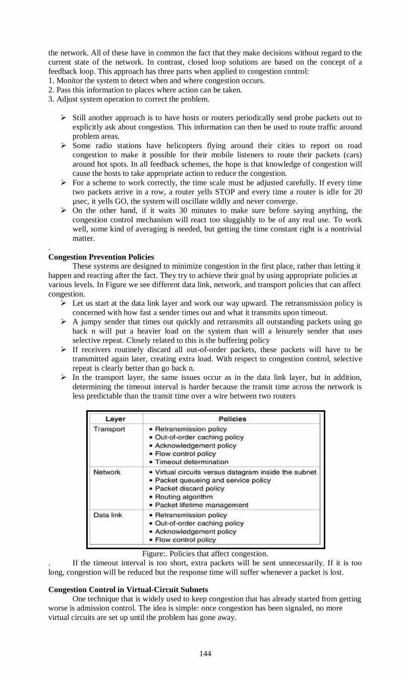
144
the network. All of these have in common the fact that they make decisions without regard to the
current state of the network. In contrast, closed loop solutions are based on the concept of a
feedback loop. This approach has three parts when applied to congestion control:
1. Monitor the system to detect when and where congestion occurs.
2. Pass this information to places where action can be taken.
3. Adjust system operation to correct the problem.
Still another approach is to have hosts or routers periodically send probe packets out to
explicitly ask about congestion. This information can then be used to route traffic around
problem areas.
Some radio stations have helicopters flying around their cities to report on road
congestion to make it possible for their mobile listeners to route their packets (cars)
around hot spots. In all feedback schemes, the hope is that knowledge of congestion will
cause the hosts to take appropriate action to reduce the congestion.
For a scheme to work correctly, the time scale must be adjusted carefully. If every time
two packets arrive in a row, a router yells STOP and every time a router is idle for 20
µsec, it yells GO, the system will oscillate wildly and never converge.
On the other hand, if it waits 30 minutes to make sure before saying anything, the
congestion control mechanism will react too sluggishly to be of any real use. To work
well, some kind of averaging is needed, but getting the time constant right is a nontrivial
matter.
.
Congestion Prevention Policies These systems are designed to minimize congestion in the first place, rather than letting it
happen and reacting after the fact. They try to achieve their goal by using appropriate policies at
various levels. In Figure we see different data link, network, and transport policies that can affect
congestion.
Let us start at the data link layer and work our way upward. The retransmission policy is
concerned with how fast a sender times out and what it transmits upon timeout.
A jumpy sender that times out quickly and retransmits all outstanding packets using go
back n will put a heavier load on the system than will a leisurely sender that uses
selective repeat. Closely related to this is the buffering policy
If receivers routinely discard all out-of-order packets, these packets will have to be
transmitted again later, creating extra load. With respect to congestion control, selective
repeat is clearly better than go back n.
In the transport layer, the same issues occur as in the data link layer, but in addition,
determining the timeout interval is harder because the transit time across the network is
less predictable than the transit time over a wire between two routers
Figure:. Policies that affect congestion.
. If the timeout interval is too short, extra packets will be sent unnecessarily. If it is too
long, congestion will be reduced but the response time will suffer whenever a packet is lost.
Congestion Control in Virtual-Circuit Subnets
One technique that is widely used to keep congestion that has already started from getting
worse is admission control. The idea is simple: once congestion has been signaled, no more
virtual circuits are set up until the problem has gone away.
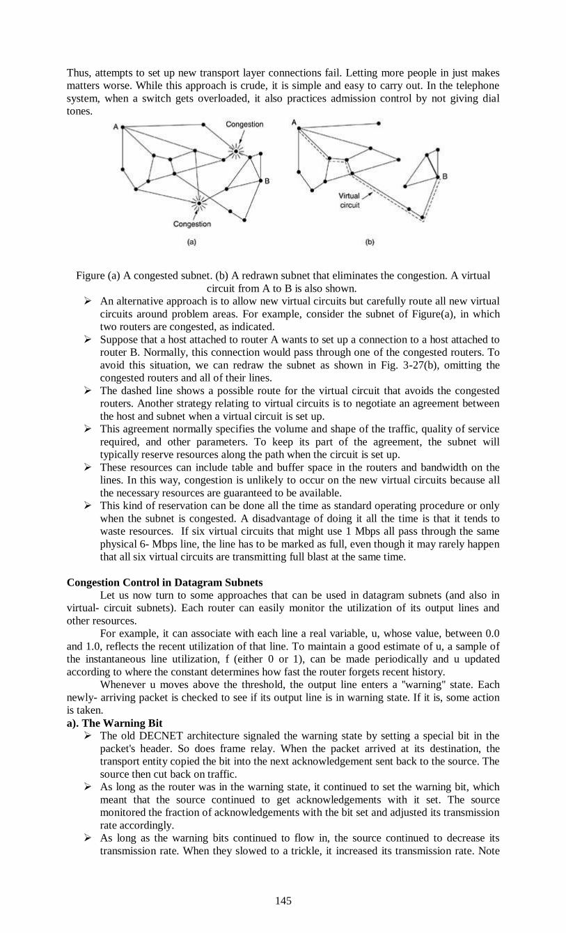
145
Thus, attempts to set up new transport layer connections fail. Letting more people in just makes
matters worse. While this approach is crude, it is simple and easy to carry out. In the telephone
system, when a switch gets overloaded, it also practices admission control by not giving dial
tones.
Figure (a) A congested subnet. (b) A redrawn subnet that eliminates the congestion. A virtual
circuit from A to B is also shown.
An alternative approach is to allow new virtual circuits but carefully route all new virtual
circuits around problem areas. For example, consider the subnet of Figure(a), in which
two routers are congested, as indicated.
Suppose that a host attached to router A wants to set up a connection to a host attached to
router B. Normally, this connection would pass through one of the congested routers. To
avoid this situation, we can redraw the subnet as shown in Fig. 3-27(b), omitting the
congested routers and all of their lines.
The dashed line shows a possible route for the virtual circuit that avoids the congested
routers. Another strategy relating to virtual circuits is to negotiate an agreement between
the host and subnet when a virtual circuit is set up.
This agreement normally specifies the volume and shape of the traffic, quality of service
required, and other parameters. To keep its part of the agreement, the subnet will
typically reserve resources along the path when the circuit is set up.
These resources can include table and buffer space in the routers and bandwidth on the
lines. In this way, congestion is unlikely to occur on the new virtual circuits because all
the necessary resources are guaranteed to be available.
This kind of reservation can be done all the time as standard operating procedure or only
when the subnet is congested. A disadvantage of doing it all the time is that it tends to
waste resources. If six virtual circuits that might use 1 Mbps all pass through the same
physical 6- Mbps line, the line has to be marked as full, even though it may rarely happen
that all six virtual circuits are transmitting full blast at the same time.
Congestion Control in Datagram Subnets
Let us now turn to some approaches that can be used in datagram subnets (and also in
virtual- circuit subnets). Each router can easily monitor the utilization of its output lines and
other resources.
For example, it can associate with each line a real variable, u, whose value, between 0.0
and 1.0, reflects the recent utilization of that line. To maintain a good estimate of u, a sample of
the instantaneous line utilization, f (either 0 or 1), can be made periodically and u updated
according to where the constant determines how fast the router forgets recent history.
Whenever u moves above the threshold, the output line enters a ''warning'' state. Each
newly- arriving packet is checked to see if its output line is in warning state. If it is, some action
is taken.
a). The Warning Bit
The old DECNET architecture signaled the warning state by setting a special bit in the
packet's header. So does frame relay. When the packet arrived at its destination, the
transport entity copied the bit into the next acknowledgement sent back to the source. The
source then cut back on traffic.
As long as the router was in the warning state, it continued to set the warning bit, which
meant that the source continued to get acknowledgements with it set. The source
monitored the fraction of acknowledgements with the bit set and adjusted its transmission
rate accordingly.
As long as the warning bits continued to flow in, the source continued to decrease its
transmission rate. When they slowed to a trickle, it increased its transmission rate. Note
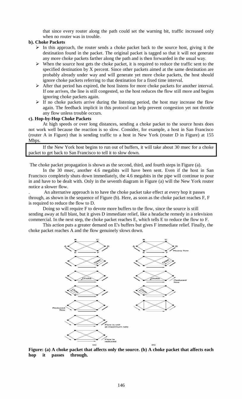
146
that since every router along the path could set the warning bit, traffic increased only
when no router was in trouble.
b). Choke Packets
In this approach, the router sends a choke packet back to the source host, giving it the
destination found in the packet. The original packet is tagged so that it will not generate
any more choke packets farther along the path and is then forwarded in the usual way.
When the source host gets the choke packet, it is required to reduce the traffic sent to the
specified destination by X percent. Since other packets aimed at the same destination are
probably already under way and will generate yet more choke packets, the host should
ignore choke packets referring to that destination for a fixed time interval.
After that period has expired, the host listens for more choke packets for another interval.
If one arrives, the line is still congested, so the host reduces the flow still more and begins
ignoring choke packets again.
If no choke packets arrive during the listening period, the host may increase the flow
again. The feedback implicit in this protocol can help prevent congestion yet not throttle
any flow unless trouble occurs.
c). Hop-by-Hop Choke Packets
At high speeds or over long distances, sending a choke packet to the source hosts does
not work well because the reaction is so slow. Consider, for example, a host in San Francisco
(router A in Figure) that is sending traffic to a host in New York (router D in Figure) at 155
Mbps.
If the New York host begins to run out of buffers, it will take about 30 msec for a choke
packet to get back to San Francisco to tell it to slow down.
The choke packet propagation is shown as the second, third, and fourth steps in Figure (a).
In the 30 msec, another 4.6 megabits will have been sent. Even if the host in San
Francisco completely shuts down immediately, the 4.6 megabits in the pipe will continue to pour
in and have to be dealt with. Only in the seventh diagram in Figure (a) will the New York router
notice a slower flow.
. An alternative approach is to have the choke packet take effect at every hop it passes
through, as shown in the sequence of Figure (b). Here, as soon as the choke packet reaches F, F
is required to reduce the flow to D.
Doing so will require F to devote more buffers to the flow, since the source is still
sending away at full blast, but it gives D immediate relief, like a headache remedy in a television
commercial. In the next step, the choke packet reaches E, which tells E to reduce the flow to F.
This action puts a greater demand on E's buffers but gives F immediate relief. Finally, the
choke packet reaches A and the flow genuinely slows down.
Figure: (a) A choke packet that affects only the source. (b) A choke packet that affects each
hop it passes through.

147
The net effect of this hop-by-hop scheme is to provide quick relief at the point of
congestion at the price of using up more buffers upstream.
Load Shedding
When none of the above methods make the congestion disappear, routers can bring out
the heavy artillery: load shedding. Load shedding is a fancy way of saying that when
routers are being inundated by packets that they cannot handle, they just throw them
away.
The term comes from the world of electrical power generation, where it refers to the
practice of utilities intentionally blacking out certain areas to save the entire grid from
collapsing on hot summer days when the demand for electricity greatly exceeds the
supply.
A step above this in intelligence requires cooperation from the senders. For many
applications, some packets are more important than others. For example, certain
algorithms for compressing video periodically transmit an entire frame and then send
subsequent frames as differences from the last full frame.
In this case, dropping a packet that is part of a difference is preferable to dropping one
that is part of a full frame. As another example, consider transmitting a document
containing ASCII text and pictures. Losing a line of pixels in some image is far less
damaging than losing a line of readable text.
To implement an intelligent discard policy, applications must mark their packets in
priority classes to indicate how important they are. If they do this, then when packets
have to be discarded, routers can first drop packets from the lowest class, then the next
lowest class, and so on.
Of course, unless there is some significant incentive to mark packets as anything other
than VERY IMPORTANT— NEVER, EVER DISCARD, nobody will do it. The
incentive might be in the form of money, with the low-priority packets being cheaper to
send than the high-priority ones.
Alternatively, senders might be allowed to send high-priority packets under conditions of
light load, but as the load increased they would be discarded, thus encouraging the users
to stop sending them.
Another option is to allow hosts to exceed the limits specified in the agreement
negotiated when the virtual circuit was set up (e.g., use a higher bandwidth than allowed),
but subject to the condition that all excess traffic be marked as low priority.
Such a strategy is actually not a bad idea, because it makes more efficient use of idle
resources, allowing hosts to use them as long as nobody else is interested, but without
establishing a right to them when times get tough.
Leaky Bucket Algorithm
The LEAKY BUCKET Algorithm generates a constant output flow. The name describes
to way of working: it works like a bucket with water and a leak on the bottom as shown in figure
How much water runs into the bucket does not matter. As long as there is any water left
in the bucket it runs out at the same constant rate defined by the leak’s size. Obviously, if there is
no water in the bucket there is no output. If the bucket is completely filled additional incoming
water gets lost.
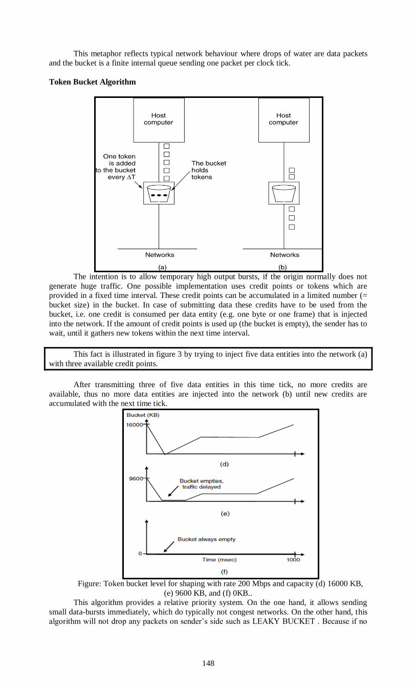
148
This metaphor reflects typical network behaviour where drops of water are data packets
and the bucket is a finite internal queue sending one packet per clock tick.
Token Bucket Algorithm
The intention is to allow temporary high output bursts, if the origin normally does not
generate huge traffic. One possible implementation uses credit points or tokens which are
provided in a fixed time interval. These credit points can be accumulated in a limited number (=
bucket size) in the bucket. In case of submitting data these credits have to be used from the
bucket, i.e. one credit is consumed per data entity (e.g. one byte or one frame) that is injected
into the network. If the amount of credit points is used up (the bucket is empty), the sender has to
wait, until it gathers new tokens within the next time interval.
This fact is illustrated in figure 3 by trying to inject five data entities into the network (a)
with three available credit points.
After transmitting three of five data entities in this time tick, no more credits are
available, thus no more data entities are injected into the network (b) until new credits are
accumulated with the next time tick.
Figure: Token bucket level for shaping with rate 200 Mbps and capacity (d) 16000 KB,
(e) 9600 KB, and (f) 0KB..
This algorithm provides a relative priority system. On the one hand, it allows sending
small data-bursts immediately, which do typically not congest networks. On the other hand, this
algorithm will not drop any packets on sender’s side such as LEAKY BUCKET . Because if no
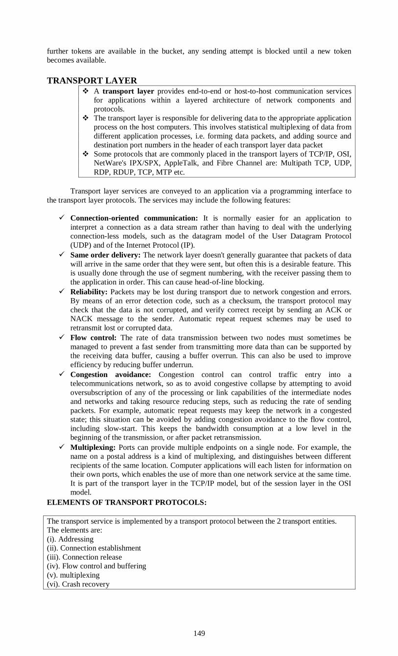
149
further tokens are available in the bucket, any sending attempt is blocked until a new token
becomes available.
TRANSPORT LAYER
A transport layer provides end-to-end or host-to-host communication services
for applications within a layered architecture of network components and
protocols.
The transport layer is responsible for delivering data to the appropriate application
process on the host computers. This involves statistical multiplexing of data from
different application processes, i.e. forming data packets, and adding source and
destination port numbers in the header of each transport layer data packet
Some protocols that are commonly placed in the transport layers of TCP/IP, OSI,
NetWare's IPX/SPX, AppleTalk, and Fibre Channel are: Multipath TCP, UDP,
RDP, RDUP, TCP, MTP etc.
Transport layer services are conveyed to an application via a programming interface to
the transport layer protocols. The services may include the following features:
Connection-oriented communication: It is normally easier for an application to
interpret a connection as a data stream rather than having to deal with the underlying
connection-less models, such as the datagram model of the User Datagram Protocol
(UDP) and of the Internet Protocol (IP).
Same order delivery: The network layer doesn't generally guarantee that packets of data
will arrive in the same order that they were sent, but often this is a desirable feature. This
is usually done through the use of segment numbering, with the receiver passing them to
the application in order. This can cause head-of-line blocking.
Reliability: Packets may be lost during transport due to network congestion and errors.
By means of an error detection code, such as a checksum, the transport protocol may
check that the data is not corrupted, and verify correct receipt by sending an ACK or
NACK message to the sender. Automatic repeat request schemes may be used to
retransmit lost or corrupted data.
Flow control: The rate of data transmission between two nodes must sometimes be
managed to prevent a fast sender from transmitting more data than can be supported by
the receiving data buffer, causing a buffer overrun. This can also be used to improve
efficiency by reducing buffer underrun.
Congestion avoidance: Congestion control can control traffic entry into a
telecommunications network, so as to avoid congestive collapse by attempting to avoid
oversubscription of any of the processing or link capabilities of the intermediate nodes
and networks and taking resource reducing steps, such as reducing the rate of sending
packets. For example, automatic repeat requests may keep the network in a congested
state; this situation can be avoided by adding congestion avoidance to the flow control,
including slow-start. This keeps the bandwidth consumption at a low level in the
beginning of the transmission, or after packet retransmission.
Multiplexing: Ports can provide multiple endpoints on a single node. For example, the
name on a postal address is a kind of multiplexing, and distinguishes between different
recipients of the same location. Computer applications will each listen for information on
their own ports, which enables the use of more than one network service at the same time.
It is part of the transport layer in the TCP/IP model, but of the session layer in the OSI
model.
ELEMENTS OF TRANSPORT PROTOCOLS:
The transport service is implemented by a transport protocol between the 2 transport entities.
The elements are:
(i). Addressing
(ii). Connection establishment
(iii). Connection release
(iv). Flow control and buffering
(v). multiplexing
(vi). Crash recovery
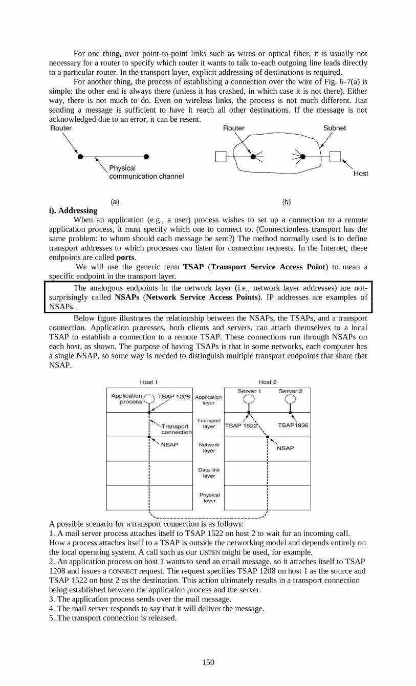
150
For one thing, over point-to-point links such as wires or optical fiber, it is usually not
necessary for a router to specify which router it wants to talk to-each outgoing line leads directly
to a particular router. In the transport layer, explicit addressing of destinations is required.
For another thing, the process of establishing a connection over the wire of Fig. 6-7(a) is
simple: the other end is always there (unless it has crashed, in which case it is not there). Either
way, there is not much to do. Even on wireless links, the process is not much different. Just
sending a message is sufficient to have it reach all other destinations. If the message is not
acknowledged due to an error, it can be resent.
i). Addressing
When an application (e.g., a user) process wishes to set up a connection to a remote
application process, it must specify which one to connect to. (Connectionless transport has the
same problem: to whom should each message be sent?) The method normally used is to define
transport addresses to which processes can listen for connection requests. In the Internet, these
endpoints are called ports.
We will use the generic term TSAP (Transport Service Access Point) to mean a
specific endpoint in the transport layer.
The analogous endpoints in the network layer (i.e., network layer addresses) are not-
surprisingly called NSAPs (Network Service Access Points). IP addresses are examples of
NSAPs.
Below figure illustrates the relationship between the NSAPs, the TSAPs, and a transport
connection. Application processes, both clients and servers, can attach themselves to a local
TSAP to establish a connection to a remote TSAP. These connections run through NSAPs on
each host, as shown. The purpose of having TSAPs is that in some networks, each computer has
a single NSAP, so some way is needed to distinguish multiple transport endpoints that share that
NSAP.
A possible scenario for a transport connection is as follows:
1. A mail server process attaches itself to TSAP 1522 on host 2 to wait for an incoming call.
How a process attaches itself to a TSAP is outside the networking model and depends entirely on
the local operating system. A call such as our LISTEN might be used, for example.
2. An application process on host 1 wants to send an email message, so it attaches itself to TSAP
1208 and issues a CONNECT request. The request specifies TSAP 1208 on host 1 as the source and
TSAP 1522 on host 2 as the destination. This action ultimately results in a transport connection
being established between the application process and the server.
3. The application process sends over the mail message.
4. The mail server responds to say that it will deliver the message.
5. The transport connection is released.
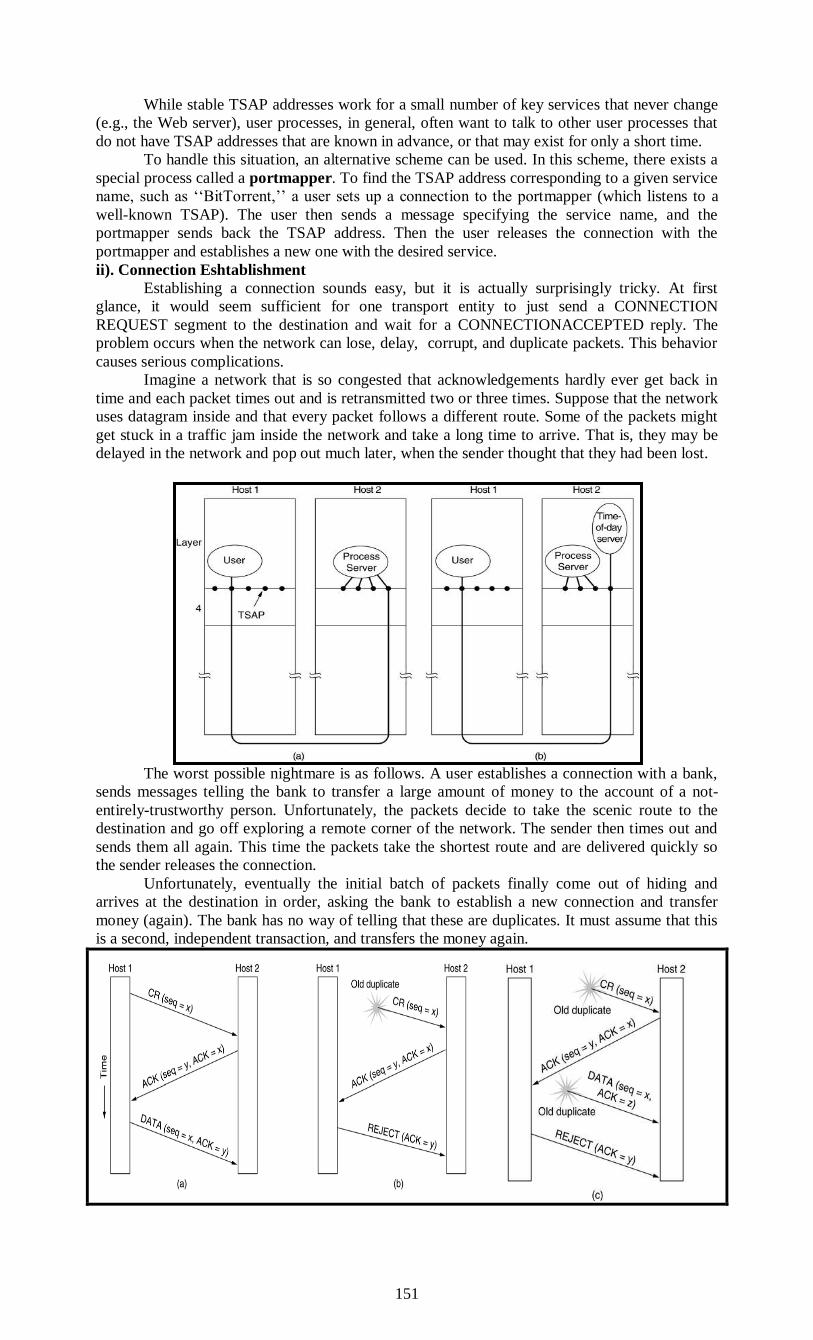
151
While stable TSAP addresses work for a small number of key services that never change
(e.g., the Web server), user processes, in general, often want to talk to other user processes that
do not have TSAP addresses that are known in advance, or that may exist for only a short time.
To handle this situation, an alternative scheme can be used. In this scheme, there exists a
special process called a portmapper. To find the TSAP address corresponding to a given service
name, such as ‘‘BitTorrent,’’ a user sets up a connection to the portmapper (which listens to a
well-known TSAP). The user then sends a message specifying the service name, and the
portmapper sends back the TSAP address. Then the user releases the connection with the
portmapper and establishes a new one with the desired service.
ii). Connection Eshtablishment
Establishing a connection sounds easy, but it is actually surprisingly tricky. At first
glance, it would seem sufficient for one transport entity to just send a CONNECTION
REQUEST segment to the destination and wait for a CONNECTIONACCEPTED reply. The
problem occurs when the network can lose, delay, corrupt, and duplicate packets. This behavior
causes serious complications.
Imagine a network that is so congested that acknowledgements hardly ever get back in
time and each packet times out and is retransmitted two or three times. Suppose that the network
uses datagram inside and that every packet follows a different route. Some of the packets might
get stuck in a traffic jam inside the network and take a long time to arrive. That is, they may be
delayed in the network and pop out much later, when the sender thought that they had been lost.
The worst possible nightmare is as follows. A user establishes a connection with a bank,
sends messages telling the bank to transfer a large amount of money to the account of a not-
entirely-trustworthy person. Unfortunately, the packets decide to take the scenic route to the
destination and go off exploring a remote corner of the network. The sender then times out and
sends them all again. This time the packets take the shortest route and are delivered quickly so
the sender releases the connection.
Unfortunately, eventually the initial batch of packets finally come out of hiding and
arrives at the destination in order, asking the bank to establish a new connection and transfer
money (again). The bank has no way of telling that these are duplicates. It must assume that this
is a second, independent transaction, and transfers the money again.
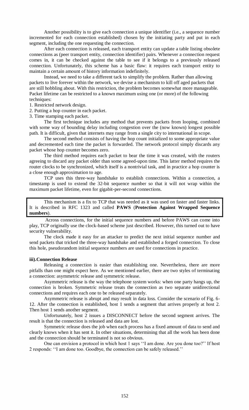
152
Another possibility is to give each connection a unique identifier (i.e., a sequence number
incremented for each connection established) chosen by the initiating party and put in each
segment, including the one requesting the connection.
After each connection is released, each transport entity can update a table listing obsolete
connections as (peer transport entity, connection identifier) pairs. Whenever a connection request
comes in, it can be checked against the table to see if it belongs to a previously released
connection. Unfortunately, this scheme has a basic flaw: it requires each transport entity to
maintain a certain amount of history information indefinitely.
Instead, we need to take a different tack to simplify the problem. Rather than allowing
packets to live forever within the network, we devise a mechanism to kill off aged packets that
are still hobbling about. With this restriction, the problem becomes somewhat more manageable.
Packet lifetime can be restricted to a known maximum using one (or more) of the following
techniques:
1. Restricted network design.
2. Putting a hop counter in each packet.
3. Time stamping each packet.
The first technique includes any method that prevents packets from looping, combined
with some way of bounding delay including congestion over the (now known) longest possible
path. It is difficult, given that internets may range from a single city to international in scope.
The second method consists of having the hop count initialized to some appropriate value
and decremented each time the packet is forwarded. The network protocol simply discards any
packet whose hop counter becomes zero.
The third method requires each packet to bear the time it was created, with the routers
agreeing to discard any packet older than some agreed-upon time. This latter method requires the
router clocks to be synchronized, which itself is a nontrivial task, and in practice a hop counter is
a close enough approximation to age.
TCP uses this three-way handshake to establish connections. Within a connection, a
timestamp is used to extend the 32-bit sequence number so that it will not wrap within the
maximum packet lifetime, even for gigabit-per-second connections.
This mechanism is a fix to TCP that was needed as it was used on faster and faster links.
It is described in RFC 1323 and called PAWS (Protection Against Wrapped Sequence
numbers).
Across connections, for the initial sequence numbers and before PAWS can come into
play, TCP originally use the clock-based scheme just described. However, this turned out to have
security vulnerability.
The clock made it easy for an attacker to predict the next initial sequence number and
send packets that tricked the three-way handshake and established a forged connection. To close
this hole, pseudorandom initial sequence numbers are used for connections in practice.
iii).Connection Release
Releasing a connection is easier than establishing one. Nevertheless, there are more
pitfalls than one might expect here. As we mentioned earlier, there are two styles of terminating
a connection: asymmetric release and symmetric release.
Asymmetric release is the way the telephone system works: when one party hangs up, the
connection is broken. Symmetric release treats the connection as two separate unidirectional
connections and requires each one to be released separately.
Asymmetric release is abrupt and may result in data loss. Consider the scenario of Fig. 6-
12. After the connection is established, host 1 sends a segment that arrives properly at host 2.
Then host 1 sends another segment.
Unfortunately, host 2 issues a DISCONNECT before the second segment arrives. The
result is that the connection is released and data are lost.
Symmetric release does the job when each process has a fixed amount of data to send and
clearly knows when it has sent it. In other situations, determining that all the work has been done
and the connection should be terminated is not so obvious.
One can envision a protocol in which host 1 says ‘‘I am done. Are you done too?’’ If host
2 responds: ‘‘I am done too. Goodbye, the connection can be safely released.’’
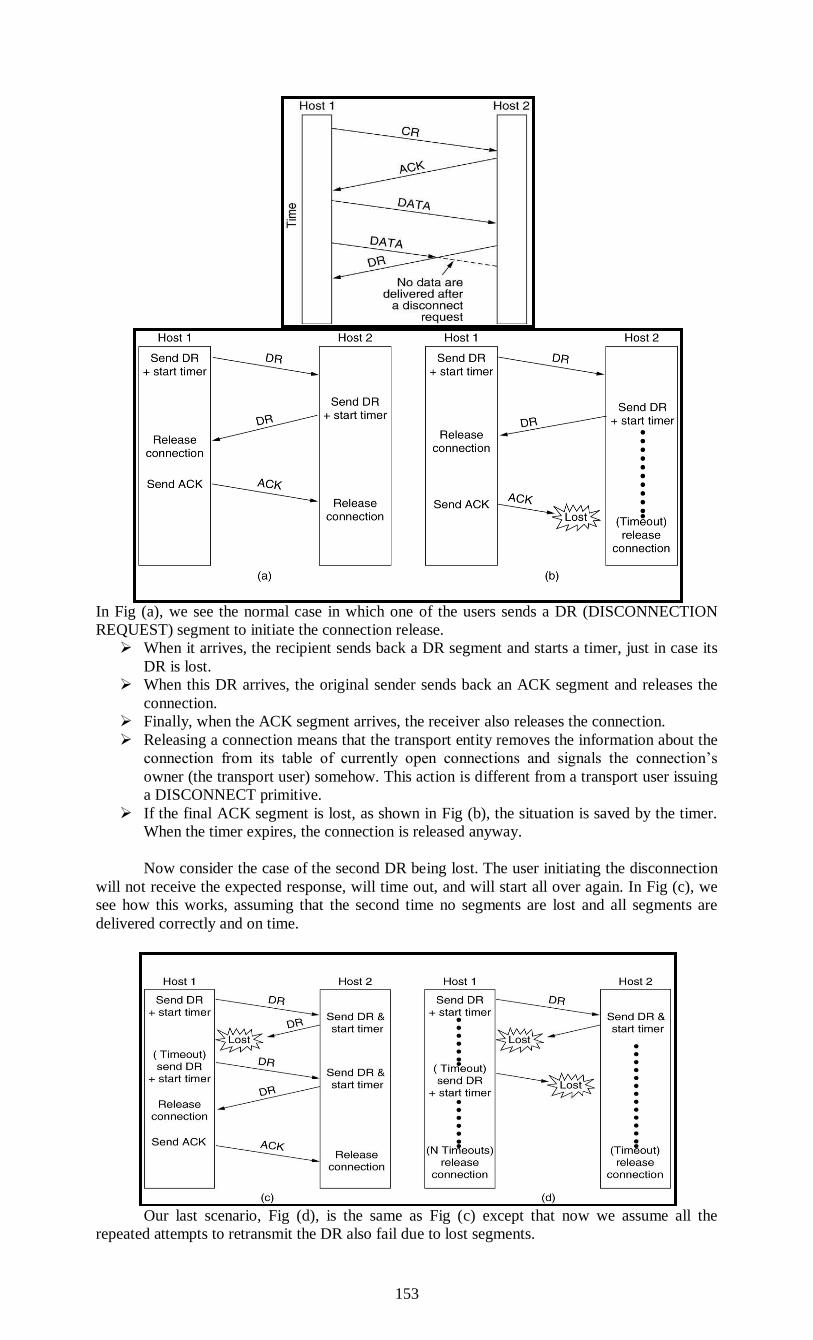
153
In Fig (a), we see the normal case in which one of the users sends a DR (DISCONNECTION
REQUEST) segment to initiate the connection release.
When it arrives, the recipient sends back a DR segment and starts a timer, just in case its
DR is lost.
When this DR arrives, the original sender sends back an ACK segment and releases the
connection.
Finally, when the ACK segment arrives, the receiver also releases the connection.
Releasing a connection means that the transport entity removes the information about the
connection from its table of currently open connections and signals the connection’s
owner (the transport user) somehow. This action is different from a transport user issuing
a DISCONNECT primitive.
If the final ACK segment is lost, as shown in Fig (b), the situation is saved by the timer.
When the timer expires, the connection is released anyway.
Now consider the case of the second DR being lost. The user initiating the disconnection
will not receive the expected response, will time out, and will start all over again. In Fig (c), we
see how this works, assuming that the second time no segments are lost and all segments are
delivered correctly and on time.
Our last scenario, Fig (d), is the same as Fig (c) except that now we assume all the
repeated attempts to retransmit the DR also fail due to lost segments.

154
After N retries, the sender just gives up and releases the connection.
Meanwhile, the receiver times out and also exits.
While this protocol usually suffices, in theory it can fail if the initial DR and N
retransmissions are all lost.
The sender will give up and release the connection, while the other side knows nothing
at all about the attempts to disconnect and is still fully active.
This situation results in a half-open connection. We could have avoided this problem
by not allowing the sender to give up after N retries and forcing it to go on forever
until it gets a response.
However, if the other side is allowed to time out, the sender will indeed go on forever,
because no response will ever be forthcoming. If we do not allow the receiving side to time out,
the protocol hangs in Fig (d).
One way to kill off half-open connections is to have a rule saying that if no segments
have arrived for a certain number of seconds, the connection is automatically disconnected. That
way, if one side ever disconnects, the other side will detect the lack of activity and also
disconnect.
This rule also takes care of the case where the connection is broken (because the network
can no longer deliver packets between the hosts) without either end disconnecting first. Of
course, if this rule is introduced, it is necessary for each transport entity to have a timer that is
stopped and then restarted whenever a segment is sent. If this timer expires, a dummy segment is
transmitted, just to keep the other side from disconnecting. On the other hand, if the automatic
disconnect rule is used and too many dummy segments in a row are lost on an otherwise idle
connection, first one side, then the other will automatically disconnect.
First it receives a request from the client, which is all the data the client will send, and
then it sends a response to the client.
When the Web server is finished with its response, all of the data has been sent in either
direction.
The server can send the client a warning and abruptly shut the connection.
If the client gets this warning, it will release its connection state then and there.
If theclient does not get the warning, it will eventually realize that the server is no longer
talking to it and release the connection state. The data has been successfully transferred in
either case.
iv). Flow Control and Buffering
Error control is ensuring that the data is delivered with the desired level of reliability,
usually that all of the data is delivered without any errors. Flow control is keeping a fast
transmitter from overrunning a slow receiver. Both of these issues have come up before, when
we studied the data link layer. The solutions that are used at the transport layer are the same
mechanisms that we studied in Chap. 3. As a very brief recap:
1. A frame carries an error-detecting code (e.g., a CRC or checksum) that is used to check if the
information was correctly received.
2. A frame carries a sequence number to identify itself and is retransmitted by the sender until it
receives an acknowledgement of successful receipt from the receiver. This is called ARQ
(Automatic Repeat reQuest).
3. There is a maximum number of frames that the sender will allow to be outstanding at any
time, pausing if the receiver is not acknowledging frames quickly enough. If this maximum is
one packet the protocol is called stop-and-wait. Larger windows enable pipelining and improve
performance on long, fast links.
4. The sliding window protocol combines these features and is also used to support bidirectional
data transfer.
For a difference in function, consider error detection. The link layer checksum protects a
frame while it crosses a single link. The transport layer checksum protects a segment while it
crosses an entire network path. It is an end-to-end check, which is not the same as having a check
on every link. Saltzer et al. (1984) describe a situation in which packets were corrupted inside a
router. The link layer checksums protected the packets only while they traveled across a link, not
while they were inside the router. Thus, packets were delivered incorrectly even though they
were correct according to the checks on every link.
This and other examples led Saltzer et al. to articulate the end-to-end argument.
According to this argument, the transport layer check that runs end-to-end is essential for
correctness, and the link layer checks are not essential but nonetheless valuable for improving
performance (since without them a corrupted packet can be sent along the entire path
unnecessarily).
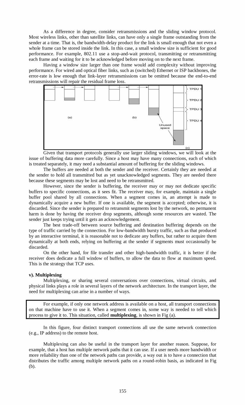
155
As a difference in degree, consider retransmissions and the sliding window protocol.
Most wireless links, other than satellite links, can have only a single frame outstanding from the
sender at a time. That is, the bandwidth-delay product for the link is small enough that not even a
whole frame can be stored inside the link. In this case, a small window size is sufficient for good
performance. For example, 802.11 use a stop-and-wait protocol, transmitting or retransmitting
each frame and waiting for it to be acknowledged before moving on to the next frame.
Having a window size larger than one frame would add complexity without improving
performance. For wired and optical fiber links, such as (switched) Ethernet or ISP backbones, the
error-rate is low enough that link-layer retransmissions can be omitted because the end-to-end
retransmissions will repair the residual frame loss.
Given that transport protocols generally use larger sliding windows, we will look at the
issue of buffering data more carefully. Since a host may have many connections, each of which
is treated separately, it may need a substantial amount of buffering for the sliding windows.
The buffers are needed at both the sender and the receiver. Certainly they are needed at
the sender to hold all transmitted but as yet unacknowledged segments. They are needed there
because these segments may be lost and need to be retransmitted.
However, since the sender is buffering, the receiver may or may not dedicate specific
buffers to specific connections, as it sees fit. The receiver may, for example, maintain a single
buffer pool shared by all connections. When a segment comes in, an attempt is made to
dynamically acquire a new buffer. If one is available, the segment is accepted; otherwise, it is
discarded. Since the sender is prepared to retransmit segments lost by the network, no permanent
harm is done by having the receiver drop segments, although some resources are wasted. The
sender just keeps trying until it gets an acknowledgement.
The best trade-off between source buffering and destination buffering depends on the
type of traffic carried by the connection. For low-bandwidth bursty traffic, such as that produced
by an interactive terminal, it is reasonable not to dedicate any buffers, but rather to acquire them
dynamically at both ends, relying on buffering at the sender if segments must occasionally be
discarded.
On the other hand, for file transfer and other high-bandwidth traffic, it is better if the
receiver does dedicate a full window of buffers, to allow the data to flow at maximum speed.
This is the strategy that TCP uses.
v). Multiplexing
Multiplexing, or sharing several conversations over connections, virtual circuits, and
physical links plays a role in several layers of the network architecture. In the transport layer, the
need for multiplexing can arise in a number of ways.
For example, if only one network address is available on a host, all transport connections
on that machine have to use it. When a segment comes in, some way is needed to tell which
process to give it to. This situation, called multiplexing, is shown in Fig (a).
In this figure, four distinct transport connections all use the same network connection
(e.g., IP address) to the remote host.
Multiplexing can also be useful in the transport layer for another reason. Suppose, for
example, that a host has multiple network paths that it can use. If a user needs more bandwidth or
more reliability than one of the network paths can provide, a way out is to have a connection that
distributes the traffic among multiple network paths on a round-robin basis, as indicated in Fig
(b).
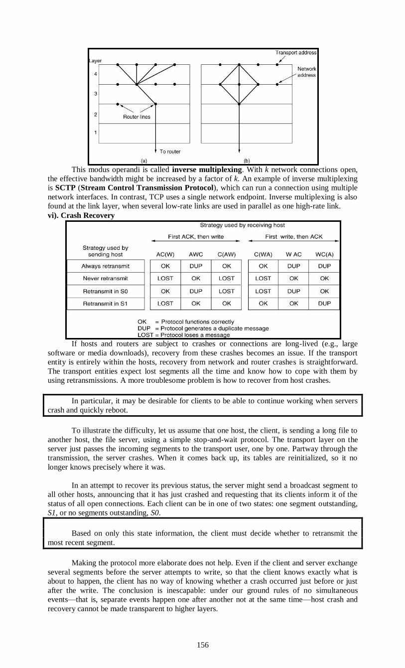
156
This modus operandi is called inverse multiplexing. With k network connections open,
the effective bandwidth might be increased by a factor of k. An example of inverse multiplexing
is SCTP (Stream Control Transmission Protocol), which can run a connection using multiple
network interfaces. In contrast, TCP uses a single network endpoint. Inverse multiplexing is also
found at the link layer, when several low-rate links are used in parallel as one high-rate link.
vi). Crash Recovery
If hosts and routers are subject to crashes or connections are long-lived (e.g., large
software or media downloads), recovery from these crashes becomes an issue. If the transport
entity is entirely within the hosts, recovery from network and router crashes is straightforward.
The transport entities expect lost segments all the time and know how to cope with them by
using retransmissions. A more troublesome problem is how to recover from host crashes.
In particular, it may be desirable for clients to be able to continue working when servers
crash and quickly reboot.
To illustrate the difficulty, let us assume that one host, the client, is sending a long file to
another host, the file server, using a simple stop-and-wait protocol. The transport layer on the
server just passes the incoming segments to the transport user, one by one. Partway through the
transmission, the server crashes. When it comes back up, its tables are reinitialized, so it no
longer knows precisely where it was.
In an attempt to recover its previous status, the server might send a broadcast segment to
all other hosts, announcing that it has just crashed and requesting that its clients inform it of the
status of all open connections. Each client can be in one of two states: one segment outstanding,
S1, or no segments outstanding, S0.
Based on only this state information, the client must decide whether to retransmit the
most recent segment.
Making the protocol more elaborate does not help. Even if the client and server exchange
several segments before the server attempts to write, so that the client knows exactly what is
about to happen, the client has no way of knowing whether a crash occurred just before or just
after the write. The conclusion is inescapable: under our ground rules of no simultaneous
events—that is, separate events happen one after another not at the same time—host crash and
recovery cannot be made transparent to higher layers.
157
Put in more general terms, this result can be restated as ‘‘recovery from a layer N crash
can only be done by layer N + 1,’’ and then only if the higher layer retains enough status
information to reconstruct where it was before the problem occurred. This is consistent with the
case mentioned above that the transport layer can recover from failures in the network layer,
provided that each end of a connection keeps track of where it is.
This problem gets us into the issue of what a so-called end-to-end acknowledgement
really means. In principle, the transport protocol is end-to-end and not chained like the lower
layers. Now consider the case of a user entering requests for transactions against a remote
database. Suppose that the remote transport entity is programmed to first pass segments to the
next layer up and then acknowledge.
Even in this case, the receipt of an acknowledgement back at the user’s machine does not
necessarily mean that the remote host stayed up long enough to actually update the database. A
truly end-to-end acknowledgement, whose receipt means that the work has actually been done
and lack thereof means that it has not, is probably impossible to achieve.
THE INTERNET TRANSPORT PROTOCOLS: TCP
UDP is a simple protocol and it has some very important uses, such as client-server
interactions and multimedia, but for most Internet applications, reliable, sequenced
delivery is needed.
UDP cannot provide this, so another protocol is required. It is called TCP and is the
main workhorse of the Internet
The different issues to be considered are:
The TCP Service Model
The TCP Protocol
The TCP Segment Header
The Connection Management
TCP Transmission Policy
TCP Congestion Control
TCP Timer Management.
Introduction to TCP
TCP (Transmission Control Protocol) was specifically designed to provide a reliable
end-to-end byte stream over an unreliable internetwork. An internetwork differs from a single
network because different parts may have wildly different topologies, bandwidths, delays, packet
sizes, and other parameters. TCP was designed to dynamically adapt to properties of the
internetwork and to be robust in the face of many kinds of failures.
TCP was formally defined in RFC 793 in September 1981. As time went on, many
improvements have been made, and various errors and inconsistencies have been fixed. To give
you a sense of the extent of TCP, the important RFCs are now RFC 793 plus: clarifications and
bug fixes in RFC 1122; extensions for high-performance in RFC 1323; selective
acknowledgements in RFC 2018; congestion control in RFC 2581; repurposing of header fields
for quality of service in RFC 2873; improved retransmission timers in RFC 2988; and explicit
congestion notification in RFC 3168. The full collection is even larger, which led to a guide to
the many RFCs, published of course as another RFC document, RFC 4614.
Each machine supporting TCP has a TCP transport entity, either a library procedure, a
user process, or most commonly part of the kernel. In all cases, it manages TCP streams and
interfaces to the IP layer.
A TCP entity accepts user data streams from local processes, breaks them up into pieces
not exceeding 64 KB (in practice, often 1460 data bytes in order to fit in a single Ethernet frame
with the IP and TCP headers), and sends each piece as a separate IP datagram.
When datagrams containing TCP data arrive at a machine, they are given to the TCP
entity, which reconstructs the original byte streams. For simplicity, we will sometimes use just
‘‘TCP’’ to mean the TCP transport entity (a piece of software) or the TCP protocol (a set of
rules). From the context it will be clear which is meant.
For example, in ‘‘the user gives TCP the data,’’ the TCP transport entity is clearly
intended. The IP layer gives no guarantee that datagrams will be delivered properly, nor any
indication of how fast datagrams may be sent. It is up to TCP to send datagrams fast enough to
make use of the capacity but not cause congestion, and to time out and retransmit any datagrams
that are not delivered. Datagrams that do arrive may well do so in the wrong order; it is also up
to TCP to reassemble them into messages in the proper sequence. In short, TCP must furnish
good performance with the reliability that most applications want and that IP does not provide.
158
The TCP Service Model TCP service is obtained by both the sender and the receiver creating end points, called
sockets, as discussed in Sec. 6.1.3. Each socket has a socket number (address) consisting of the
IP address of the host and a 16-bit number local to that host, called a port. A port is the TCP
name for a TSAP. For TCP service to be obtained, a connection must be explicitly established
between a socket on one machine and a socket on another machine. The socket calls are listed in
figure.
A socket may be used for multiple connections at the same time. In other words, two or
more connections may terminate at the same socket. Connections are identified by the socket
identifiers at ends that is, (socket1, socket2). No virtual circuit numbers or other identifiers are
used. Port numbers below 1024 are reserved for standard services that can usually only be started
by privileged users (e.g., root in UNIX systems). They are called well-known ports. For
example, any process wishing to remotely retrieve mail from a host can connect to the
destination host’s port 143 to contact its IMAP Other ports from 1024 through 49151 can be
registered with IANA for use by unprivileged users, but applications can and do choose their
own ports.
For example, the BitTorrent peer-to-peer file-sharing application (unofficially) uses ports
6881–6887, but may run on other ports as well. It would certainly be possible to have the FTP
daemon attach itself to port 21 at boot time, the SSH daemon attach itself to port 22 at boot time,
and so on.
However, doing so would clutter up memory with daemons that were idle most of the
time. Instead, what is commonly done is to have a single daemon, called inetd (Internet
daemon) in UNIX, attach itself to multiple ports and wait for the first incoming connection.
When that occurs, inetd forks off a new process and executes the appropriate daemon in it,
letting that daemon handle the request. In this way, the daemons other than inetd are only active
when there is work for them to do. Inetd learns which ports it is to use from a configuration file.
Consequently, the system administrator can set up the system to have permanent daemons on the
busiest ports (e.g., port 80) and inetd on the rest.
All TCP connections are full duplex and point-to-point. Full duplex means that traffic can
go in both directions at the same time. Point-to-point means that each connection has exactly two
end points. TCP does not support multicasting or broadcasting.
A TCP connection is a byte stream, not a message stream. Message boundaries are not
preserved end to end. For example, if the sending process does four 512-byte writes to a TCP
stream, these data may be delivered to the receiving process as four 512-byte chunks, two 1024-
byte chunks, one 2048-byte chunk or some other way. There is no way for the receiver to detect
the unit(s) in which the data were written, no matter how hard it tries. Files in UNIX have this
property too. The reader of a file cannot tell whether the file was written a block at a time, a byte
at a time, or all in one blow. As with a UNIX file, the TCP software has no idea of what the
bytes mean and no interest in finding out. A byte is just a byte.
When an application passes data to TCP, TCP may send it immediately or buffer it (in
order to collect a larger amount to send at once), at its discretion.
However, sometimes the application really wants the data to be sent immediately. For
example, suppose a user of an interactive game wants to send a stream of updates. It is essential
that the updates be sent immediately, not buffered until there is a collection of them. To force
data out, TCP has the notion of a PUSH flag that is carried on packets. The original intent was to
let applications tell TCP implementations via the PUSH flag not to delay the transmission.
However, applications cannot literally set the PUSH flag when they send data. Instead, different
operating systems have evolved different options to expedite transmission (e.g., TCP
NODELAY in Windows and Linux).
For Internet archaeologists, we will also mention one interesting feature of TCP service
that remains in the protocol but is rarely used: urgent data. When an application has high
priority data that should be processed immediately, for example, if an interactive user hits the
CTRL-C key to break off a remote computation that has already begun, the sending application
can put some control information in the data stream and give it to TCP along with the URGENT
flag. This event causes TCP to stop accumulating data and transmit everything it has for that
connection immediately.
When the urgent data are received at the destination, the receiving application is
interrupted (e.g., given a signal in UNIX terms) so it can stop whatever it was doing and read the
data stream to find the urgent data. The end of the urgent data is marked so the application
knows when it is over. The start of the urgent data is not marked. It is up to the application to
figure that out.
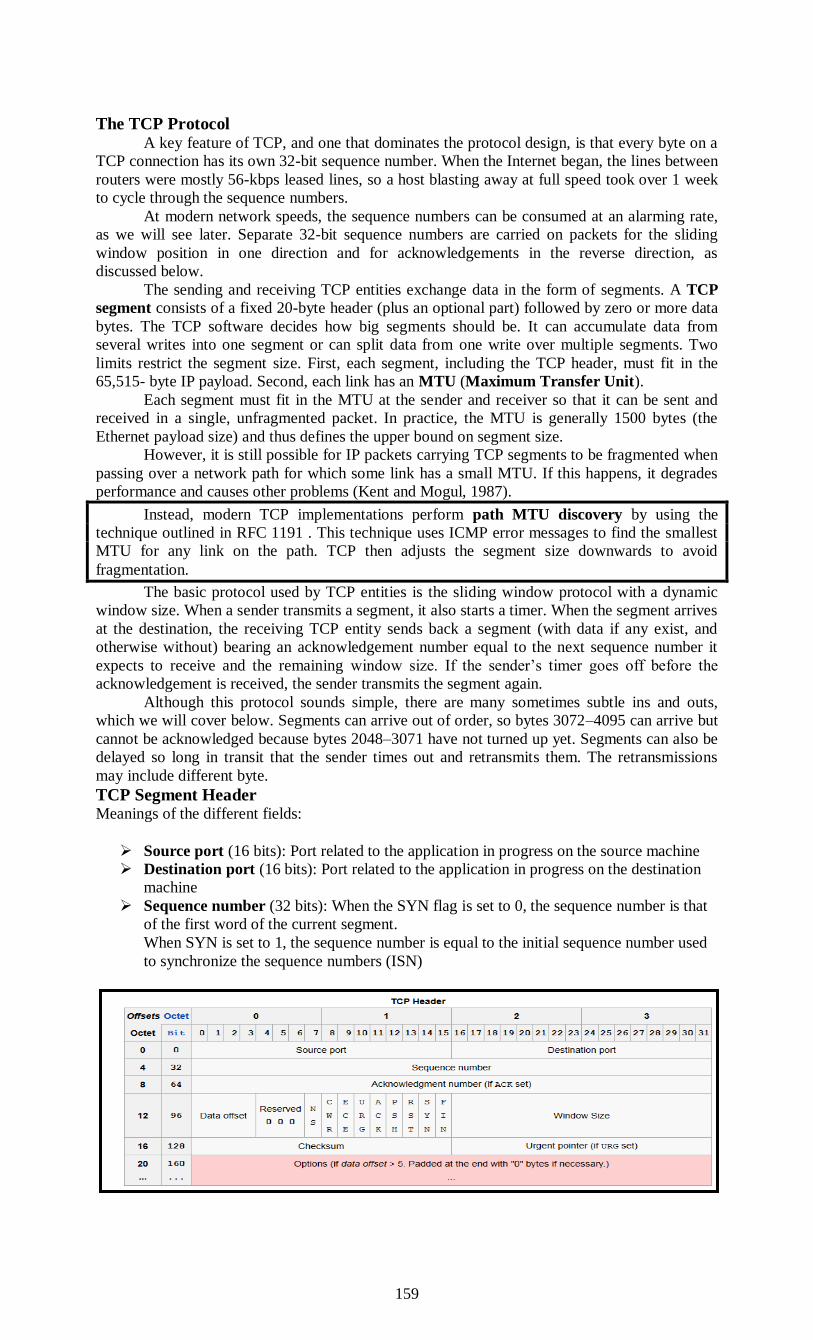
159
The TCP Protocol A key feature of TCP, and one that dominates the protocol design, is that every byte on a
TCP connection has its own 32-bit sequence number. When the Internet began, the lines between
routers were mostly 56-kbps leased lines, so a host blasting away at full speed took over 1 week
to cycle through the sequence numbers.
At modern network speeds, the sequence numbers can be consumed at an alarming rate,
as we will see later. Separate 32-bit sequence numbers are carried on packets for the sliding
window position in one direction and for acknowledgements in the reverse direction, as
discussed below.
The sending and receiving TCP entities exchange data in the form of segments. A TCP
segment consists of a fixed 20-byte header (plus an optional part) followed by zero or more data
bytes. The TCP software decides how big segments should be. It can accumulate data from
several writes into one segment or can split data from one write over multiple segments. Two
limits restrict the segment size. First, each segment, including the TCP header, must fit in the
65,515- byte IP payload. Second, each link has an MTU (Maximum Transfer Unit).
Each segment must fit in the MTU at the sender and receiver so that it can be sent and
received in a single, unfragmented packet. In practice, the MTU is generally 1500 bytes (the
Ethernet payload size) and thus defines the upper bound on segment size.
However, it is still possible for IP packets carrying TCP segments to be fragmented when
passing over a network path for which some link has a small MTU. If this happens, it degrades
performance and causes other problems (Kent and Mogul, 1987).
Instead, modern TCP implementations perform path MTU discovery by using the
technique outlined in RFC 1191 . This technique uses ICMP error messages to find the smallest
MTU for any link on the path. TCP then adjusts the segment size downwards to avoid
fragmentation.
The basic protocol used by TCP entities is the sliding window protocol with a dynamic
window size. When a sender transmits a segment, it also starts a timer. When the segment arrives
at the destination, the receiving TCP entity sends back a segment (with data if any exist, and
otherwise without) bearing an acknowledgement number equal to the next sequence number it
expects to receive and the remaining window size. If the sender’s timer goes off before the
acknowledgement is received, the sender transmits the segment again.
Although this protocol sounds simple, there are many sometimes subtle ins and outs,
which we will cover below. Segments can arrive out of order, so bytes 3072–4095 can arrive but
cannot be acknowledged because bytes 2048–3071 have not turned up yet. Segments can also be
delayed so long in transit that the sender times out and retransmits them. The retransmissions
may include different byte.
TCP Segment Header Meanings of the different fields:
Source port (16 bits): Port related to the application in progress on the source machine
Destination port (16 bits): Port related to the application in progress on the destination
machine
Sequence number (32 bits): When the SYN flag is set to 0, the sequence number is that
of the first word of the current segment.
When SYN is set to 1, the sequence number is equal to the initial sequence number used
to synchronize the sequence numbers (ISN)

160
Acknowledgement number (32 bits): The acknowledgement number, also called the
acquittal number relates to the (sequence) number of the last segment expected and not
the number of the last segment received.
Data offset (4 bits): This makes it possible to locate the start of the data in the packet.
Here, the offset is vital because the option field is a variable size
Reserved (6 bits): A currently unused field but provided for future use
Flags (6x1 bit): The flags represent additional information:
URG: if this flag is set to 1 the packet must be processed urgently
ACK: if this flag is set to 1 the packet is an acknowledgement.
PSH (PUSH): if this flag is set to 1 the packet operates according to the PUSH
method.
RST: if this flag is set to 1 the connection is reset.
SYN: The TCP SYN flag indicates a request to establish a connection.
FIN: if this flag is set to 1 the connection is interrupted.
Window (16 bits): Field making it possible to know the number of bytes that the
recipient wants to receive without acknowledgement
Checksum (CRC): The checksum is conducted by taking the sum of the header data
field, so as to be able to check the integrity of the header
Urgent pointer (16 bits): Indicates the sequence number after which information
becomes urgent
Options (variable size): Various options
Padding: Space remaining after the options is padded with zeros to have a length which
is a multiple of 32 bits
Protocol operations
TCP protocol operations may be divided into three phases. Connections must be properly
established in a multi-step handshake process (connection establishment) before entering the data
transfer phase. After data transmission is completed, the connection termination closes
established virtual circuits and releases all allocated resources.
A TCP connection is managed by an operating system through a programming interface
that represents the local end-point for communications, the Internet socket. During the lifetime of
a TCP connection the local end-point undergoes a series of state changes.
LISTEN
(server) represents waiting for a connection request from any remote TCP and port.
SYN-SENT
(client) represents waiting for a matching connection request after having sent a
connection request.
SYN-RECEIVED

161
(server) represents waiting for a confirming connection request acknowledgment after
having both received and sent a connection request.
ESTABLISHED
(both server and client) represents an open connection, data received can be delivered to
the user. The normal state for the data transfer phase of the connection.
FIN-WAIT-1
(both server and client) represents waiting for a connection termination request from the
remote TCP, or an acknowledgment of the connection termination request previously
sent.
FIN-WAIT-2
(both server and client) represents waiting for a connection termination request from the
remote TCP.
CLOSE-WAIT
(both server and client) represents waiting for a connection termination request from the
local user.
CLOSING
(both server and client) represents waiting for a connection termination request
acknowledgment from the remote TCP.
LAST-ACK
(both server and client) represents waiting for an acknowledgment of the connection
termination request previously sent to the remote TCP (which includes an
acknowledgment of its connection termination request).
TIME-WAIT
(either server or client) represents waiting for enough time to pass to be sure the remote
TCP received the acknowledgment of its connection termination request. [According to
RFC 793 a connection can stay in TIME-WAIT for a maximum of four minutes known
as a MSL (maximum segment lifetime).]
CLOSED
(both server and client) represents no connection state at all.
Reliability of transfers
The TCP protocol makes it possible to ensure reliable data transfer, although it uses the
IP protocol, which does not include any monitoring of datagram delivery.
In reality, the TCP protocol has an acknowledgement system enabling the client and
server to ensure mutual receipt of data.
When a segment is issued, a sequence number is linked to it. Upon receipt of a data segment,
the recipient machine will return a data segment where the ACK flag is set to 1 (in order to
signal that it is an acknowledgement) accompanied by an acknowledgement number equal to the
previous sequence number.
In addition, using a timer which starts upon receipt of a segment at the level of the
originator machine, the segment is resent when the time allowed has passed, because in this case
the originator machine considers that the segment is lost.
However, if the segment is not lost and it arrives at the destination, the recipient machine
will know, thanks to the sequence number that it is a duplication and will only retain the last
segment arrived at the destination.
Establishing a connection
Considering that this communication process, which takes place using data transmission
and acknowledgement, is based on a sequence number, the originator and recipient machines
(client and server) must know the initial sequence number of the other machine.
Establishing the connection between two applications is often done according to the
following schema:
The TCP ports must be open
The application on the server is passive, i.e. the application is listening, awaiting a
connection
The application on the client makes a connection request to the server where the
application is passive open. The application on the client is said to be "active open"
The two machines must then synchronize their sequences using a mechanism commonly
called a three ways handshake that is also found during the closure of the session.
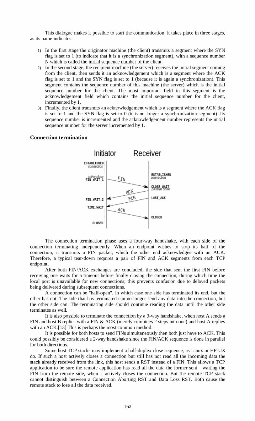
162
This dialogue makes it possible to start the communication, it takes place in three stages,
as its name indicates:
1) In the first stage the originator machine (the client) transmits a segment where the SYN
flag is set to 1 (to indicate that it is a synchronization segment), with a sequence number
N which is called the initial sequence number of the client.
2) In the second stage, the recipient machine (the server) receives the initial segment coming
from the client, then sends it an acknowledgement which is a segment where the ACK
flag is set to 1 and the SYN flag is set to 1 (because it is again a synchronization). This
segment contains the sequence number of this machine (the server) which is the initial
sequence number for the client. The most important field in this segment is the
acknowledgement field which contains the initial sequence number for the client,
incremented by 1.
3) Finally, the client transmits an acknowledgement which is a segment where the ACK flag
is set to 1 and the SYN flag is set to 0 (it is no longer a synchronization segment). Its
sequence number is incremented and the acknowledgement number represents the initial
sequence number for the server incremented by 1.
Connection termination
The connection termination phase uses a four-way handshake, with each side of the
connection terminating independently. When an endpoint wishes to stop its half of the
connection, it transmits a FIN packet, which the other end acknowledges with an ACK.
Therefore, a typical tear-down requires a pair of FIN and ACK segments from each TCP
endpoint.
After both FIN/ACK exchanges are concluded, the side that sent the first FIN before
receiving one waits for a timeout before finally closing the connection, during which time the
local port is unavailable for new connections; this prevents confusion due to delayed packets
being delivered during subsequent connections.
A connection can be "half-open", in which case one side has terminated its end, but the
other has not. The side that has terminated can no longer send any data into the connection, but
the other side can. The terminating side should continue reading the data until the other side
terminates as well.
It is also possible to terminate the connection by a 3-way handshake, when host A sends a
FIN and host B replies with a FIN & ACK (merely combines 2 steps into one) and host A replies
with an ACK.[13] This is perhaps the most common method.
It is possible for both hosts to send FINs simultaneously then both just have to ACK. This
could possibly be considered a 2-way handshake since the FIN/ACK sequence is done in parallel
for both directions.
Some host TCP stacks may implement a half-duplex close sequence, as Linux or HP-UX
do. If such a host actively closes a connection but still has not read all the incoming data the
stack already received from the link, this host sends a RST instead of a FIN. This allows a TCP
application to be sure the remote application has read all the data the former sent—waiting the
FIN from the remote side, when it actively closes the connection. But the remote TCP stack
cannot distinguish between a Connection Aborting RST and Data Loss RST. Both cause the
remote stack to lose all the data received.

163
Some application protocols may violate the OSI model layers, using the TCP open/close
handshaking for the application protocol open/close handshaking — these may find the RST
problem on active close. As an example:
s = connect(remote);
send(s, data);
close(s);
For a usual program flow like above, a TCP/IP stack like that described above does not
guarantee that all the data arrives to the other application.
TCP timer management
TCP uses multiple timers (at least conceptually) to do its work. The most important of
these is the RTO (Retransmission TimeOut). When a segment is sent, a retransmission timer is
started. If the segment is acknowledged before the timer expires, the timer is stopped. If, on the
other hand, the timer goes off before the acknowledgement comes in, the segment is
retransmitted (and the timer OS started again).
The question that arises is: how long should the timeout be? This problem is much more
difficult in the transport layer than in data link protocols such as 802.11. In the latter case, the
expected delay is measured in microseconds and is highly predictable (i.e., has a low variance),
so the timer can be set to go off just slightly after the acknowledgement is expected.
The timeout is doubled on each successive retransmission until the segments get through
the first time. This fix is called Karn’s algorithm (Karn and Partridge, 1987). Most TCP
implementations use it.
TCP uses 3 kinds of timers:
1. Retransmission timer
2. Persistence timer
3. Keep-Alive timer.
1. Retransmission timer
When a segment is sent, a timer is started. If the segment is acknowledged before the
timer expires, the timer is stopped. If on the other hand, the timer goes off before the
acknowledgement comes in, the segment is retransmitted and the timer is started again.
The algorithm that constantly adjusts the time-out interval, based on continuous
measurements of n/w performance was proposed by JACOBSON and works as follows:
for each connection, TCP maintains a variable RTT, that is the best current estimate of the round
trip time to the destination in question.
When a segment is sent, a timer is started, both to see how long the acknowledgement
takes and to trigger a retransmission if it takes too long.
If the acknowledgement gets back before the timer expires, TCP measures how long the
measurements took say M
It then updates RTT according to the formula
RTT = αRTT + ( 1-α ) M
Where α = a smoothing factor that determines how much weight is given to
the old value. Typically, α =7/8
Retransmission timeout is calculated as
D = α D + ( 1-α ) | RTT-M |
Where D = another smoothed variable, Mean Deviation
RTT = expected acknowledgement value
M = observed acknowledgement value
Timeout = RTT+(4*D)
2. Persistence timer:
It is designed to prevent the following deadlock: the receiver sends an acknowledgement
with a window size of ‘0’ telling the sender to wait later, the receiver updates the window, but
the packet with the update is lost now both the sender and receiver are waiting for each other to
do something
_ when the persistence timer goes off, the sender transmits a probe to the receiver
_ the response to the probe gives the window size
_ if it is still zero, the persistence timer is set again and the cycle repeats
_ if it is non zero, data can now be sent
3. Keep-Alive timer:
When a connection has been idle for a long time, this timer may go off to cause one side
to check if other side is still there. If it fails to respond, the connection is terminated.
164
Congestion control The final main aspect of TCP is congestion control. TCP uses a number of mechanisms to
achieve high performance and avoid congestion collapse, where network performance can fall by
several orders of magnitude. These mechanisms control the rate of data entering the network,
keeping the data flow below a rate that would trigger collapse. They also yield an approximately
max-min fair allocation between flows.
Acknowledgments for data sent, or lack of acknowledgments, are used by senders to infer
network conditions between the TCP sender and receiver. Coupled with timers, TCP senders and
receivers can alter the behavior of the flow of data. This is more generally referred to as
congestion control and/or network congestion avoidance.
Modern implementations of TCP contain four intertwined algorithms: Slow-start,
congestion avoidance, fast retransmit, and fast recovery (RFC 5681).
In addition, senders employ a retransmission timeout (RTO) that is based on the
estimated round-trip time (or RTT) between the sender and receiver, as well as the variance in
this round trip time. The behavior of this timer is specified in RFC 6298. There are subtleties in
the estimation of RTT. For example, senders must be careful when calculating RTT samples for
retransmitted packets; typically they use Karn's Algorithm or TCP timestamps (see RFC 1323).
These individual RTT samples are then averaged over time to create a Smoothed Round
Trip Time (SRTT) using Jacobson's algorithm. This SRTT value is what is finally used as the
round-trip time estimate.
Enhancing TCP to reliably handle loss, minimize errors, manage congestion and go fast
in very high-speed environments are ongoing areas of research and standards development. As a
result, there are a number of TCP congestion avoidance algorithm variations.
Selective acknowledgments
Relying purely on the cumulative acknowledgment scheme employed by the original
TCP protocol can lead to inefficiencies when packets are lost. For example, suppose 10,000
bytes are sent in 10 different TCP packets, and the first packet is lost during transmission. In a
pure cumulative acknowledgment protocol, the receiver cannot say that it received bytes 1,000 to
9,999 successfully, but failed to receive the first packet, containing bytes 0 to 999. Thus the
sender may then have to resend all 10,000 bytes.
To solve this problem TCP employs the selective acknowledgment (SACK) option,
defined in RFC 2018, which allows the receiver to acknowledge discontinuous blocks of packets
which were received correctly, in addition to the sequence number of the last contiguous byte
received successively, as in the basic TCP acknowledgment. The acknowledgement can specify a
number of SACK blocks, where each SACK block is conveyed by the starting and ending
sequence numbers of a contiguous range that the receiver correctly received. In the example
above, the receiver would send SACK with sequence numbers 1000 and 9999. The sender thus
retransmits only the first packet, bytes 0 to 999.
A TCP sender can interpret an out-of-order packet delivery as a lost packet. If it does so,
the TCP sender will retransmit the packet previous to the out-of-order packet and slow its data
delivery rate for that connection. The duplicate-SACK option, an extension to the SACK option
that was defined in RFC 2883, solves this problem. The TCP receiver sends a D-ACK to indicate
that no packets were lost, and the TCP sender can then reinstate the higher transmission rate.
The SACK option is not mandatory and it is used only if both parties support it. This is
negotiated when connection is established. SACK uses the optional part of the TCP header (see
TCP segment structure for details). The use of SACK is widespread — all popular TCP stacks
support it. Selective acknowledgment is also used in Stream Control Transmission Protocol
(SCTP).
Window scaling
For more efficient use of high bandwidth networks, a larger TCP window size may be
used. The TCP window size field controls the flow of data and its value is limited to between
2 and 65,535 bytes.
Since the size field cannot be expanded, a scaling factor is used. The TCP window scale
option, as defined in RFC 1323, is an option used to increase the maximum window size from
65,535 bytes to 1 gigabyte. Scaling up to larger window sizes is a part of what is necessary for
TCP Tuning.
The window scale option is used only during the TCP 3-way handshake. The window
scale value represents the number of bits to left-shift the 16-bit window size field. The window
scale value can be set from 0 (no shift) to 14 for each direction independently. Both sides must
send the option in their SYN segments to enable window scaling in either direction.
Some routers and packet firewalls rewrite the window scaling factor during a
transmission. This causes sending and receiving sides to assume different TCP window sizes.
165
The result is non-stable traffic that may be very slow. The problem is visible on some sites
behind a defective router.
TCP timestamps TCP timestamps, defined in RFC 1323, can help TCP determine in which order packets
were sent. TCP timestamps are not normally aligned to the system clock and start at some
random value. Many operating systems will increment the timestamp for every elapsed
millisecond; however the RFC only states that the ticks should be proportional. There are two
timestamp fields:
a 4-byte sender timestamp value (my timestamp)
4-byte echoes reply timestamp value (the most recent timestamp received from
you).
TCP timestamps are used in an algorithm known as Protection against Wrapped
Sequence numbers, or PAWS (see RFC 1323 for details). PAWS is used when the TCP window
size exceeds the possible numbers of sequence numbers (232). In the case where a packet was
potentially retransmitted it answers the question: "Is this sequence number in the first 4 GB or
the second?" And the timestamp is used to break the tie.
Also, the Eifel detection algorithm (RFC 3522) uses TCP timestamps to determine if
retransmissions are occurring because packets are lost or simply out of order.
Out-of-band data
One is able to interrupt or abort the queued stream instead of waiting for the stream to finish.
This is done by specifying the data as urgent. This tells the receiving program to process it
immediately, along with the rest of the urgent data. When finished, TCP informs the application
and resumes back to the stream queue. An example is when TCP is used for a remote login
session, the user can send a keyboard sequence that interrupts or aborts the program at the other
end. These signals are most often needed when a program on the remote machine fails to operate
correctly. The signals must be sent without waiting for the program to finish its current transfer.
TCP OOB data was not designed for the modern Internet. The urgent pointer only alters the
processing on the remote host and doesn't expedite any processing on the network itself. When it
gets to the remote host there are two slightly different interpretations of the protocol, which
means only single bytes of OOB data are reliable. This is assuming it is reliable at all as it is one
of the least commonly used protocol elements and tends to be poorly implemented.
UNIT IV
QUESTIONS
SECTION A:
1. What are the responsibilities of a Network layer?
2. What are the types of Routing algorithms?
3. -------- is the process of selecting paths in a network along which to send data on
physical traffic.
4. -------- Routing algorithms allow routers to automatically discover and maintain
awareness of the paths through the network.
5. -------- routing algorithm is sometimes called by other names including Bellman-
Ford or Ford-Fulkerson.
6. What are the processes included in Link state routing?
7. What is Congestion?
8. What is Jitter control?
9. What is Load Shedding?
10. -------- provides end-to-end or host-to-host communication services for
applications within a layered architecture of network components and protocols.
SECTION B
1. Write short notes on Routing algorithms.
2. Discuss about Link state routing algorithm.
3. Discuss about Shortest path routing algorithm.
4. Write short notes on Congestion control in virtual subnets.
5. Explain about Load Shedding.
6. Write short notes on Leaky bucket algorithm and Token bucket algorithm.
7. Explain Connection establishment & Connection release in TCP.

166
8. Write short notes on TCP segment header.
9. Write short notes on TCP Timer Management.
10. Write short notes on Congestion control.
SECTION C
1. Explain briefly about Bell-ford and Ford Fulkerson algorithm.
2. Explain the types of Routing algorithms in detail.
3. What is congestion control? Explain the congestion control techniques in detail.
4. Explain 1). Leaky bucket algorithm 2). Token bucket Algorithm 3). Jitter Control.
5. Explain in detail about the Elements of Transport protocols.
6.
UNIT-V
APPLICATION LAYER: DNS – E-mail. NETWORK SECURITY:
Cryptography– Symmetric Key Algorithms – Public Key Algorithms – Digital
Signatures.
Application layer
It involves interesting, real applications doing
work
for the end user.
• Primary function: (probably) to provide an
interface to the end user.
• Some protocols exist for enhancing services to
applications:
security protocols (see Chapter 8)
domain Name System (DNS)
electronic Mail
the World Wide Web
streaming media
content delivery
• Common applications:
email readers
web browsers
multimedia
167
DNS – THE DOMAIN NAME SYSTEM: • Problem: how to resolve domain names to IP
addresses?
• DNS properties
hierarchical domain-based naming scheme
distributed database to implement it
original definition in RFCs 1034, 1035
• Operation:
application program calls library routine
resolver
resolver sends UDP packet to DNS server
server returns IP address to resolver
resolver returns address to application
DNS Name Space
• Similar to postal system naming hierarchy
• Several hundred top-level domains
domains are partitioned into sub domains
sub domains are partitioned further
• Original top-level domains:
countries
generic: com, edu, gov, int, mil, net, org
• A domain is named by the path upward to an unnamed root.
Resource Records
• Most common: IP address
• Record format includes:
domain name
time to live
class
type
value
• Record types:
SOA - start of authority
A - IPv4 address of a host
AAAA - IPv6 address of a host
MX - mail exchange
NS - name server
CNAME - canonical name
PTR - pointer
SPF - sender policy framework
SRV - service
TXT - text
Managing a large and constantly changing set of names is a nontrivial problem. In the
postal system, name management is done by requiring letters to specify (implicitly or explicitly)
the country, state or province, city, and street address of the addressee. company and contain
thousands of hosts. The Internet is divided into over 200 top-level domains, where each domain
covers many hosts.
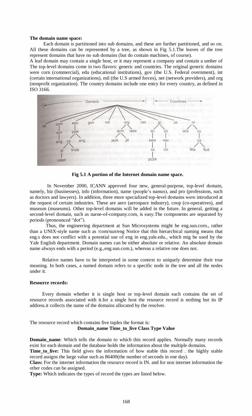
168
The domain name space:
Each domain is partitioned into sub domains, and these are further partitioned, and so on.
All these domains can be represented by a tree, as shown in Fig 5.1.The leaves of the tree
represent domains that have no sub domains (but do contain machines, of course).
A leaf domain may contain a single host, or it may represent a company and contain a umber of
The top-level domains come in two flavors: generic and countries. The original generic domains
were corn (commercial), edu (educational institutions), gov (the U.S. Federal overnment), int
(certain international organizations), mil (the U.S armed forces), net (network providers), and org
(nonprofit organization). The country domains include one entry for every country, as defined in
ISO 3166.
Fig 5.1 A portion of the Internet domain name space.
In November 2000, ICANN approved four new, general-purpose, top-level domain,
namely, biz (businesses), info (information), name (people’s names), and pro (professions, such
as doctors and lawyers). In addition, three more specialized top-level domains were introduced at
the request of certain industries. These are aero (aerospace industry), coop (co-operatives), and
museum (museums). Other top-level domains will be added in the future. In general, getting a
second-level domain, such as narne-of-company.com, is easy.The components are separated by
periods (pronounced “dot”).
Thus, the engineering department at Sun Microsystems might be eng.sun.corn., rather
than a UNIX-style name such as /com/sun/eng Notice that this hierarchical naming means that
eng.s does not conflict with a potential use of eng in eng.yale.edu., which mig be used by the
Yale English department. Domain names can be either absolute or relative. An absolute domain
name always ends with a period (e.g.,eng.sun.com.), whereas a relative one does not.
Relative names have to be interpreted in some context to uniquely determine their true
meaning. In both cases, a named domain refers to a specific node in the tree and all the nodes
under it.
Resource records:
Every domain whether it is single host or top-level domain each contains the set of
resource records associated with it.for a single host the resource record is nothing but its IP
address.it collects the name of the domains allocated by the resolver.
The resource record which contains five tuples the format is:
Domain_name Time_to_live Class Type Value
Domain_name: Which tells the domain to which this record applies. Normally many records
exist for each domain and the database holds the information about the multiple domains.
Time_to_live: This field gives the information of how stable this record . the highly stable
record assigns the large value such as 86400(the number of seconds in one day).
Class: For the internet information the resource record is IN. and for non internet information the
other codes can be assigned.
Type: Which indicates the types of record the types are listed below.
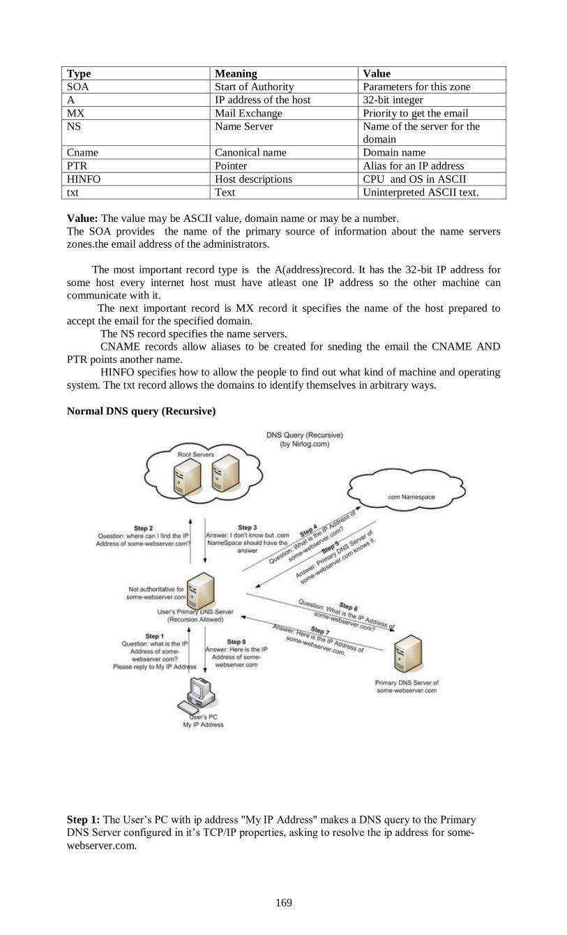
169
Type Meaning Value
SOA Start of Authority Parameters for this zone
A IP address of the host 32-bit integer
MX Mail Exchange Priority to get the email
NS Name Server Name of the server for the
domain
Cname Canonical name Domain name
PTR Pointer Alias for an IP address
HINFO Host descriptions CPU and OS in ASCII
txt Text Uninterpreted ASCII text.
Value: The value may be ASCII value, domain name or may be a number.
The SOA provides the name of the primary source of information about the name servers
zones.the email address of the administrators.
The most important record type is the A(address)record. It has the 32-bit IP address for
some host every internet host must have atleast one IP address so the other machine can
communicate with it.
The next important record is MX record it specifies the name of the host prepared to
accept the email for the specified domain.
The NS record specifies the name servers.
CNAME records allow aliases to be created for sneding the email the CNAME AND
PTR points another name.
HINFO specifies how to allow the people to find out what kind of machine and operating
system. The txt record allows the domains to identify themselves in arbitrary ways.
Normal DNS query (Recursive)
Step 1: The User’s PC with ip address "My IP Address" makes a DNS query to the Primary
DNS Server configured in it’s TCP/IP properties, asking to resolve the ip address for some-
webserver.com.
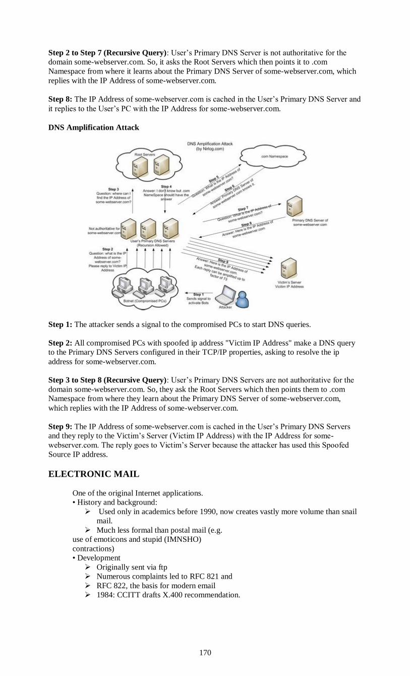
170
Step 2 to Step 7 (Recursive Query): User’s Primary DNS Server is not authoritative for the
domain some-webserver.com. So, it asks the Root Servers which then points it to .com
Namespace from where it learns about the Primary DNS Server of some-webserver.com, which
replies with the IP Address of some-webserver.com.
Step 8: The IP Address of some-webserver.com is cached in the User’s Primary DNS Server and
it replies to the User’s PC with the IP Address for some-webserver.com.
DNS Amplification Attack
Step 1: The attacker sends a signal to the compromised PCs to start DNS queries.
Step 2: All compromised PCs with spoofed ip address "Victim IP Address" make a DNS query
to the Primary DNS Servers configured in their TCP/IP properties, asking to resolve the ip
address for some-webserver.com.
Step 3 to Step 8 (Recursive Query): User’s Primary DNS Servers are not authoritative for the
domain some-webserver.com. So, they ask the Root Servers which then points them to .com
Namespace from where they learn about the Primary DNS Server of some-webserver.com,
which replies with the IP Address of some-webserver.com.
Step 9: The IP Address of some-webserver.com is cached in the User’s Primary DNS Servers
and they reply to the Victim’s Server (Victim IP Address) with the IP Address for some-
webserver.com. The reply goes to Victim’s Server because the attacker has used this Spoofed
Source IP address.
ELECTRONIC MAIL
One of the original Internet applications.
• History and background:
Used only in academics before 1990, now creates vastly more volume than snail
mail.
Much less formal than postal mail (e.g.
use of emoticons and stupid (IMNSHO)
contractions)
• Development
Originally sent via ftp
Numerous complaints led to RFC 821 and
RFC 822, the basis for modern email
1984: CCITT drafts X.400 recommendation.
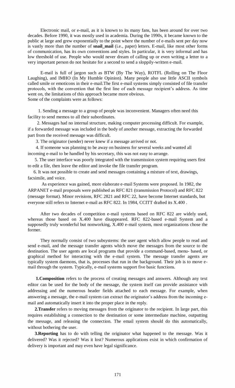
171
Electronic mail, or e-mail, as it is known to its many fans, has been around for over two
decades. Before 1990, it was mostly used in academia. During the 1990s, it became known to the
public at large and grew exponentially to the point where the number of e-mails sent per day now
is vastly more than the number of snail_mail (i.e., paper) letters. E-mail, like most other forms
of communication, has its own conventions and styles. In particular, it is very informal and has
low threshold of use. People who would never dream of calling up or even writing a letter to a
very important person do not hesitate for a second to send a sloppily-written e-mail.
E-mail is full of jargon such as BTW (By The Way), ROTFL (Rolling on The Floor
Laughing), and IMHO (In My Humble Opinion). Many people also use little ASCII symbols
called smile or emoticons in their e-mail.The first e-mail systems simply consisted of file transfer
protocols, with the convention that the first line of each message recipient’s address. As time
went on, the limitations of this approach became more obvious.
Some of the complaints were as follows:
1. Sending a message to a group of people was inconvenient. Managers often need this
facility to send memos to all their subordinates.
2. Messages had no internal structure, making computer processing difficult. For example,
if a forwarded message was included in the body of another message, extracting the forwarded
part from the received message was difficult.
3. The originator (sender) never knew if a message arrived or not.
4. If someone was planning to be away on business for several weeks and wanted all
incoming e-mail to be handled by his secretary, this was not easy to arrange.
5. The user interface was poorly integrated with the transmission system requiring users first
to edit a file, then leave the editor and invoke the file transfer program.
6. It was not possible to create and send messages containing a mixture of text, drawings,
facsimile, and voice.
As experience was gained, more elaborate e-mail Systems were proposed. In 1982, the
ARPANET e-mail proposals were published as RFC 821 (transmission Protocol) and RFC 822
(message format). Minor revisions, RFC 2821 and RFC 22, have become Internet standards, but
everyone still refers to Internet e-mail as RFC 822. In 1984, CCITT drafted its X.400 .
After two decades of competition e-mail systems based on RFC 822 are widely used,
whereas those based on X.400 have disappeared. RFC 822-based e-mail System and a
supposedly truly wonderful but nonworking, X.400 e-mail system, most organizations chose the
former.
They normally consist of two subsystems: the user agent which allow people to read and
send e-mail, and the message transfer agents which move the messages from the source to the
destination. The user agents are local programs that provide a command-based, menu- based, or
graphical method for interacting with the e-mail system. The message transfer agents are
typically system daemons, that is, processes that run in the background. Their job is to move e-
mail through the system. Typically, e-mail systems support five basic functions.
1.Composition refers to the process of creating messages and answers. Although any text
editor can be used for the body of the message, the system itself can provide assistance with
addressing and the numerous header fields attached to each message. For example, when
answering a message, the e-mail system can extract the originator’s address from the incoming e-
mail and automatically insert it into the proper place in the reply.
2.Transfer refers to moving messages from the originator to the recipient. In large part, this
requires establishing a connection to the destination or some intermediate machine, outputting
the message, and releasing the connection. The email system should do this automatically,
without bothering the user.
3.Reporting has to do with telling the originator what happened to the message. Was it
delivered? Was it rejected? Was it lost? Numerous applications exist in which confirmation of
delivery is important and may even have legal significance.

172
4.Displaying incoming messages is needed so people can read their e-mail
Sometimes conversion is required or a special viewer must be invoked, if then message is a
PostScript file or digitized voice. Simple conversion formatting are sometimes attempted as well.
5. Disposition is the final step and concerns what the recipient does with the message after
receiving it. Possibilities include throwing it away before read’° throwing it away after reading,
saving it, and so on. It should also be possible to retrieve and reread saved messages, forward
them, or process them other ways.
THE USER AGENT
Normally a program that accepts a variety of
commands for composing, receiving, replying, etc.
• Typical elements:
message summary screen
ability to organize messages
searching
• Addressing formats:
DNS-based: user@dns-address (example: [email protected])
X.400: Attribute=value pairs separated by slashes
Example:
/C=US/ST=MASSACHUSETTS/L=CAMBRIDGE.
E-mail systems have two basic parts: The user agents and the message transfer agents. A
user agent is a program (sometimes called a mail reader) that accepts a
as for commands for composing, receiving, and replying to messages, as well manipulating
mailboxes. Some user agents have a fancy menu- or icon driven interface that requires a mouse,
whereas others expect 1-character commands from the keyboard. Functionally, these are the
same. Some systems are menu or icon-driven but also have keyboard shortcuts.
SENDING E-MAIL
To send an e-mail message, a user must provide the message, the destination address, and
possibly some other parameters. The message can be produced with a free-standing text editor, a
word processing program, or possibly with a specialized text editor built into the user agent. The
destination address must be in a format that the user agent can deal with. Many user agents
expect addresses of the form user@dns-address.
They are composed of attribute = value pairs separated by slashes. This address specifies a
country, state, locality, personal address and a common name (Ken Smith). Many other attributes
are possible so can send to someone whose exact e-mail address do not know, provided an
enough other attributes.
READING E-MAIL:
When a user agent is started up, it looks at the user’s mailbox for incoming e-mail before
displaying anything on the screen. Then it may announce the number of messages in the mailbox
or display a one-line summary of each one and wait for command.
# Flags Bytes Sender Subject
1 K 1030 asw Changes to MINIX
2 KA 6348 trudy Not all Trudy’s are nasty
3 K F 4519 Amy N.Wong Request for information
4 1236 bal Bioinformatics
5 104110 kaashoek Material on peer-to-peer
6 1223 Frank Re:Will review a grant proposal
7 3110 guido Our paper has been accepted
8 1204 dmr Re:My student’s visit
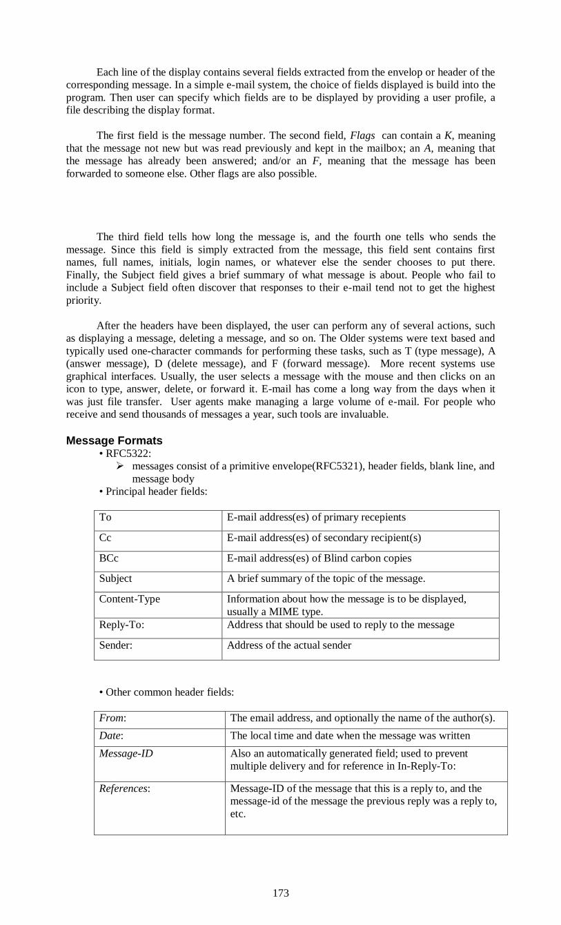
173
Each line of the display contains several fields extracted from the envelop or header of the
corresponding message. In a simple e-mail system, the choice of fields displayed is build into the
program. Then user can specify which fields are to be displayed by providing a user profile, a
file describing the display format.
The first field is the message number. The second field, Flags can contain a K, meaning
that the message not new but was read previously and kept in the mailbox; an A, meaning that
the message has already been answered; and/or an F, meaning that the message has been
forwarded to someone else. Other flags are also possible.
The third field tells how long the message is, and the fourth one tells who sends the
message. Since this field is simply extracted from the message, this field sent contains first
names, full names, initials, login names, or whatever else the sender chooses to put there.
Finally, the Subject field gives a brief summary of what message is about. People who fail to
include a Subject field often discover that responses to their e-mail tend not to get the highest
priority.
After the headers have been displayed, the user can perform any of several actions, such
as displaying a message, deleting a message, and so on. The Older systems were text based and
typically used one-character commands for performing these tasks, such as T (type message), A
(answer message), D (delete message), and F (forward message). More recent systems use
graphical interfaces. Usually, the user selects a message with the mouse and then clicks on an
icon to type, answer, delete, or forward it. E-mail has come a long way from the days when it
was just file transfer. User agents make managing a large volume of e-mail. For people who
receive and send thousands of messages a year, such tools are invaluable.
Message Formats
• RFC5322:
messages consist of a primitive envelope(RFC5321), header fields, blank line, and
message body
• Principal header fields:
To E-mail address(es) of primary recepients
Cc E-mail address(es) of secondary recipient(s)
BCc E-mail address(es) of Blind carbon copies
Subject A brief summary of the topic of the message.
Content-Type Information about how the message is to be displayed,
usually a MIME type.
Reply-To: Address that should be used to reply to the message
Sender: Address of the actual sender
• Other common header fields:
From: The email address, and optionally the name of the author(s).
Date: The local time and date when the message was written
Message-ID Also an automatically generated field; used to prevent
multiple delivery and for reference in In-Reply-To:
References: Message-ID of the message that this is a reply to, and the
message-id of the message the previous reply was a reply to,
etc.

174
The Multipurpose Internet Mail Extensions (MIME)
In the early days, all email was in English and used ASCII.
• Problems with this approach:
Cannot represent various non-English characters or character sets
Cannot represent non-textual data (e.g. audio, video)
• MIME (RFCs 2045-2049, 4288, 4289):
Continues to use RFC 822 format with
more structure plus encoding rules
• MIME (RFCs 2045-2049, 4288, 4289):
Continues to use RFC 822 format with more structure plus encoding rules
message headers
Message headers
MIME-Version
Identifies the MIME-version.
Content-Description
The original MIME specifications only described the structure
of mail messages.
Content-Type
This header indicates the Internet media type of the message
content
Content-Transfer-Encoding
How the body wrapped for transmission
MIME Content Types
• Defines the nature of the message body
text textual information. The primary subtype, "plain", indicates plain (unformatted)
text
multipart data consisting of multiple parts of independent data types.
message an encapsulated message. A body of Content-Type "message"
image image data. Image requires a display device (such as a graphical display, a printer,
or a FAX machine) to view the information.
audio audio data, with initial subtype "basic". Audio requires an audio output device
(such as a speaker or a telephone) to "display" the contents.
video video data. Video requires the capability to display moving images, typically
including specialized hardware and software. The initial subtype is "mpeg".
application
Message Transfer:
The message transfer systems is concerned with relaying messages from source to the
destination.The simplest way to send the message is by establishing the transport connection
between source to destination.
SMTP:The Simple Mail Transfer Protocol:
Within the internet connection to deliver the message from source to destination the TCP
connection should be established. the message transfer system will speaks with the SMTP
SMTP accepts the incoming connections and copies the messages from the mail box.SMTP
is a simple ASCII protocol.when all the email has been exchanged in both directionthe
connection is to be released.
It is completely well defined few problem can still arise.one is related to message lengththe
another one is related with time outs.
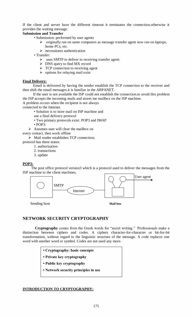
175
If the client and server have the different timeout it terminates the connection.otherwise it
provides the waiting message.
Submission and Transfer
• Submission: performed by user agents
originally ran on same computers as message transfer agent now run on laptops,
home PCs, etc.
necessitates authentication
• Transfer:
uses SMTP to deliver to receiving transfer agent:
DNS query to find MX record
TCP connection to receiving agent
options for relaying mail exist
Final Delivery:
Email is delivered by having the sender establish the TCP connection to the receiver and
then shift the email messages.it is familiar in the ARPANET.
If the user is not available the ISP could not establish the connection.to avoid this problem
the ISP accepts the incoming mails and stores ine mailbox on the ISP machine.
A problem occurs when the recipient is not always
connected to the Internet.
• Solution is to store mail on ISP machine and
use a final delivery protocol
• Two primary protocols exist: POP3 and IMAP
• POP3:
Assumes user will clear the mailbox on
every contact, then work offline
Mail reader establishes TCP connection;
protocol has three states:
1. authorization
2. transactions
3. update
POP3:
The post office protocol version3 which is a protocol used to deliver the messages from the
ISP machine to the client machines.
User agent
SMTP
Sending host Mail box
NETWORK SECURITY CRYPTOGRAPHY
Cryptography comes from the Greek words for “secret writing.” Professionals make a
distinction between ciphers and codes. A ciphers character-for-character or bit-for-bit
transformation, without regard to the linguistic structure of the message. A code replaces one
word with another word or symbol. Codes are not used any more.
INTRODUCTION TO CRYPTOGRAPHY:
Internet
• Cryptography: basic concepts
• Private key cryptography
• Public key cryptography
• Network security principles in use
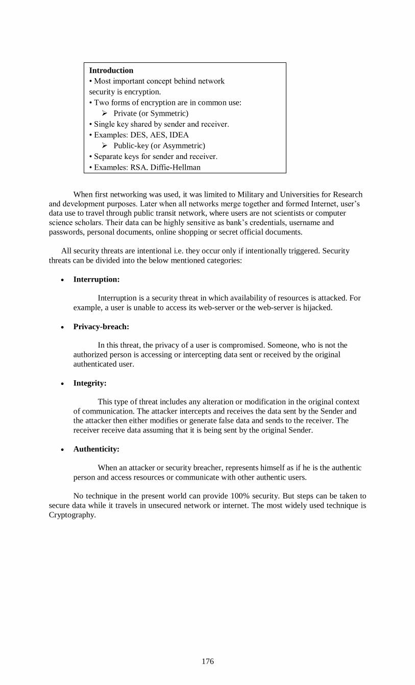
176
When first networking was used, it was limited to Military and Universities for Research
and development purposes. Later when all networks merge together and formed Internet, user’s
data use to travel through public transit network, where users are not scientists or computer
science scholars. Their data can be highly sensitive as bank’s credentials, username and
passwords, personal documents, online shopping or secret official documents.
All security threats are intentional i.e. they occur only if intentionally triggered. Security
threats can be divided into the below mentioned categories:
Interruption:
Interruption is a security threat in which availability of resources is attacked. For
example, a user is unable to access its web-server or the web-server is hijacked.
Privacy-breach:
In this threat, the privacy of a user is compromised. Someone, who is not the
authorized person is accessing or intercepting data sent or received by the original
authenticated user.
Integrity:
This type of threat includes any alteration or modification in the original context
of communication. The attacker intercepts and receives the data sent by the Sender and
the attacker then either modifies or generate false data and sends to the receiver. The
receiver receive data assuming that it is being sent by the original Sender.
Authenticity:
When an attacker or security breacher, represents himself as if he is the authentic
person and access resources or communicate with other authentic users.
No technique in the present world can provide 100% security. But steps can be taken to
secure data while it travels in unsecured network or internet. The most widely used technique is
Cryptography.
Introduction
• Most important concept behind network
security is encryption.
• Two forms of encryption are in common use:
Private (or Symmetric)
• Single key shared by sender and receiver.
• Examples: DES, AES, IDEA
Public-key (or Asymmetric)
• Separate keys for sender and receiver.
• Examples: RSA, Diffie-Hellman

177
Cryptography is a technique to encrypt the plain-text data which makes it difficult to
understand and interpret. There are several cryptographic algorithm available present day as
described below:
Secret Key
Public Key
Message Digest
Secret Key Encryption
Both sender and receiver have one secret key. This secret key is used to encrypt the data
at sender’s end. After encrypting the data, it is then sent on the public domain to the receiver.
Because the receiver knows and has the Secret Key, the encrypted data packets can easily be
decrypted.
Example of secret key encryption is DES. In Secret Key encryption it is required to have a
separate key for each host on the network making it difficult to manage.
Public Key Encryption
In this encryption system, every user has its own Secret Key and it is not in the shared
domain. The secret key is never revealed on public domain. Along with secret key, every user
has its own but public key. Public key is always made public and is used by Senders to encrypt
the data. When the user receives the encrypted data, he can easily decrypt it by using its own
Secret Key. Example of public key encryption is RSA.
Message Digest
In this method, the actual data is not sent instead a hash value is calculated and sent. The
other end user, computes its own hash value and compares with the one just received. The both
hash values matches, it is accepted otherwise rejected.
Four groups of people have used and contributed to the art of cryptography. The military, the
diplomatic corps, diarists, and lovers. The military has had the most important role and has
shaped the field over the centuries. Within military organizations, the messages to be encrypted
have traditionally been given to poorly-paid, low-level code clerks for encryption and
transmission. The sheer volume of messages prevented this work from being done by a few elite
specialists.
Until the advent of computers, one of the main constraints on cryptography had been the
ability of the code clerk to perform the necessary transformations, often on a battlefield with
little equipment. An additional constraint has been the difficulty in switching over quickly from
one cryptographic method to another one, since this entails retraining a large number of people.

178
The danger of a code clerk being captured by the enemy has made it essential to be able to
change the cryptographic method instantly if need be.
The encryption model (for a symmetric-key cipher).
The messages to be encrypted, known as the plaintext, are transformed by a function that
is parameterized by a key. The output of the encryption process, known as the ciphertext, is then
transmitted, often by messenger or radio. Assume that the enemy or intruder hears and accurately
copies down the complete ciphertext.
However, unlike the intended recipient, he does not know what the decryption key is and
so cannot decrypt the ciphertext easily. Sometimes the intruder can not only listen to the
communication channel (passive intruder) but can also record messages and play them back
later, inject his own messages, or modify legitimate messages before they get to the receiver
(active intruder).
The art of breaking ciphers, called cryptanalysis and the art devising them (cryptography)
is collectively known as Cryptology.It will often be useful to have a notation for relating
plaintext, ciphertext and keys. We will use C = EK(P) to mean that the encryption of the plaintext
key K gives the ciphertext C. Similarly, P = DK(C) represents the decryption of C to get the
plaintext again. It then follows that DK(EK(P)) = P .
This notation suggests that E and D are just mathematical functions, which they are. The
only tricky part is that both are functions of two parameters, and we have written one of the
parameters (the key) as a subscript, rather than as an argument, to distinguish it from the
message.
A fundamental rule of cryptography is that one must assume that the cryptanalyst knows
the methods used for encryption and decryption. In other words, the cryptanalyst knows how the
encryption method, E, and decryption, D.
The amount of effort necessary to invent, test, and install a new algorithm every time the
old method is compromised (or thought to be compromised) has always made it impractical to
keep the encryption algorithm secret.. The key consists of a (relatively) short string that selects
one of many potential encryptions.
In contrast to the general method, which may only be changed every few years, the key
can be changed as often as required. Thus, our basic model is a stable and publicly-known
general method parameterized by a secret and easily changed key. The idea that the cryptanalyst
knows the algorithms and that the secrecy lies exclusively in the keys is called Kerckhoff’s
principle, named after the Flemish military cryptographer AuguSte Kerckhoff who first stated it
in 1883 (Kerckhoff, 1883).
Kerckhoff’s principle: All algorithms must be public; only the keys are secret
The longer the key, higher the work factor the cryptanalyst has to deal with. •The work
factor for breaking the system by exhaustive search of the key space is exponential in the key
length. Secrecy comes from having a strong (but public) algorithm and a long key. To prevent
kid brother from reading e-mail, 64-bit keys will do. For routine commercial use, at least 128

179
bits should be used. To keep major governments at bay. keys of at least 256 bits, preferably
more, are needed. From the cryptanalyst’s point of view, the cryptanalysis- problem has three
principal variations. When he has a quantity of ciphertext and no plaintext, he is confronted with
the ciphertext-only problem.
The cryptograms that appear in the puzzle section of newspapers pose this kind of
problem. When the cryptanalyst has some matched ciphertext and plaintext, the problem is called
the known plaintext problem. Finally, when the cryptanalyst has the ability to encrypt pieces of
plaintext of his own choosing, we have the chosen plaintext problem.
Novices in the cryptography business often assume that if a cipher can withstand a
ciphertext-only attack, it is secure. This assumption is very naive. In many cases the cryptanalyst
can make a good guess at parts of the plaintext. Equipped with some matched plaintext-
ciphertext pairs, the cryptanalyst’s job becomes much easier. To achieve security, the
cryptographer should be conservative and make sure that the system is unbreakable even if his
opponent can encrypt arbitrary amounts of chosen plaintext. Encryption methods have
historically been divided into two categories: substitution ciphers and transposition ciphers.
SUBSTITUTION CIPHERS:
In a substitution cipher each letter or group of letters is replaced by another letter or
group of letters to disguise it. One of the oldest known ciphers is the attributed to Julius Caesar.
In this method, a becomes D, b becomes E, c becomes F,..., and z becomes C. For example,
attack becomes WWDFN.
In examples, plaintext will be given in lower case letters, and cipher- ext in upper case
letters. The next improvement is to have each of the symbols in the plaintext 26 letters for
simplicity, map onto some other letter. For example,
the general system of symbol-for-symbol substitution is called a monoalphabetic substitution,
with the key being the 26-letter string corresponding to the full alphabet.
For the key above, the plaintext attack would be transformed into the ciphertext QZZQEA.
At first glance this might appear to be a safe system because although the cryptanalyst knows the
general system (letter-for-letter substitution), he does not know which of the 26! 4 x 1026
possible keys is in use. Given a surprisingly small amount of ciphertext, the cipher can be broken
easily. The basic attack takes advantage of the statistical properties of natural languages. In
English, for example, e is the most common letter, followed by t, o, a, n, i, etc. The most
common two-letter combinations, or digrams, are th, in, er, re, and an. The most common three-
letter combinations, or trigrams, are the, ing, and, and ion.
A cryptanalyst trying to break a monoalphabetic cipher would start out by counting the relative
frequencies of all letters in the ciphertext.
1. Caesar Cipher
Earliest known substitution cipher.
Replace each letter of the alphabet with the letter
three places after that alphabet.
Alphabets are assumed to be wrapped around (Z is
followed by A, etc.).
P: H A P P Y N E W Y E A R
C: K D S S B Q H Z B H D U
Mono-alphabetic Cipher
Allow any arbitrary substitution.
There can be 26! possible keys.
A typical key may be:
(ZAQWSXCDERFVBGTYHNMJUIKLOP)
Drawback:
• We can make guesses by observing the relative
frequency of letters in the text.
• Compare it with standard frequency distribution
charts in English (say).
• Also look at the frequency of diagrams and
trigrams, for which tables are also available.
• Easy to break in general.
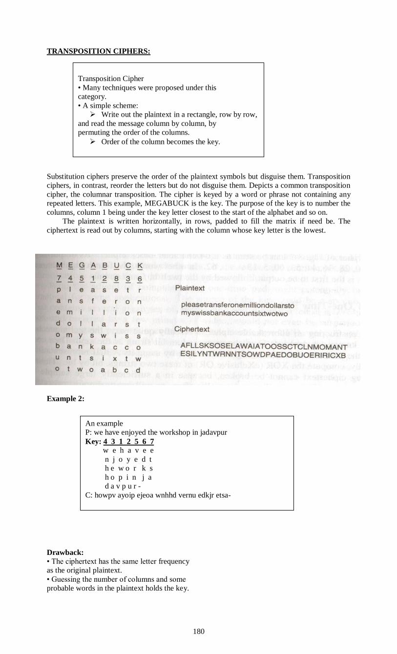
180
TRANSPOSITION CIPHERS:
Substitution ciphers preserve the order of the plaintext symbols but disguise them. Transposition
ciphers, in contrast, reorder the letters but do not disguise them. Depicts a common transposition
cipher, the columnar transposition. The cipher is keyed by a word or phrase not containing any
repeated letters. This example, MEGABUCK is the key. The purpose of the key is to number the
columns, column 1 being under the key letter closest to the start of the alphabet and so on.
The plaintext is written horizontally, in rows, padded to fill the matrix if need be. The
ciphertext is read out by columns, starting with the column whose key letter is the lowest.
Example 2:
Drawback:
• The ciphertext has the same letter frequency
as the original plaintext.
• Guessing the number of columns and some
probable words in the plaintext holds the key.
Transposition Cipher
• Many techniques were proposed under this
category.
• A simple scheme:
Write out the plaintext in a rectangle, row by row,
and read the message column by column, by
permuting the order of the columns.
Order of the column becomes the key.
An example
P: we have enjoyed the workshop in jadavpur
Key: 4 3 1 2 5 6 7
w e h a v e e
n j o y e d t
h e w o r k s
h o p i n j a
d a v p u r -
C: howpv ayoip ejeoa wnhhd vernu edkjr etsa-

181
A transposition cipher
To break a transposition cipher, the cryptanalyst must first be aware that he is dealing
with a transposition cipher. By looking at the frequency of E, T, A, 0, 1, N, etc., t is easy to see if
they fit the normal pattern for plaintext. The next step is to make a guess at the number of
columns.
In many cases a probable word or phrase may be guessed at from the context. For
example, suppose that our cryptanalyst suspects that the plaintext phrase milliondollars occurs
somewhere in the message. Observe that digrams MO, IL, IL, LA, JR and OS Occur in the
ciphertext as a result of this phrase wrapping around. The ciphertext letter 0 follows the
ciphertext letter M (i.e., they are vertically adjacent in column 4) because they are separated in
the probable phrase by a distance equal to the key length. If a key of length seven had been used,
the digrams MD, 10, LL, LL, OR, and NS would have occurred instead. In fact, for each key
length, a different set of digrams is produced in the ciphertext. By hunting for the Various
possibilities, the cryptanalyst can often easily determine the key length. The remaining step is to
order the columns. When the number of columns, k, is small, each of the k(k - 1) column pairs
can be examined to see if its digram frequencies match those for English plaintext. The pair with
the best match is assumed to be correctly positioned.
Now each remaining column is tentatively tried as the successor to this pair. The column
whose digram and trigram frequencies give the best match is tentatively assumed to be correct.
The predecessor column is found in the same way. The entire process is continued until a
potential ordering is found. Chances are that the plaintext will be recognizable at this point (e.g.,
if million occurs, it is clear what the error is).
Some transposition ciphers accept a fixed-length block of input and produce a fixed-length block
of output. These ciphers can be completely described by giving a list telling the order in which
the characters are to be output.
ONE-TIME PADS:
First choose a random bit string as the key. Then convert the plaintext into a bit string, for
example by using its ASCII representation. Finally, compute the XOR (exclusive OR) of these
two strings, bit by bit. The resulting ciphertext cannot be broken, because in a sufficiently large
sample of ciphertext, each letter will occur equally, as will every digram, every trigram, and so
on. This method, known as the one-time pad, is immune to all present and future attacks no
matter how much computational power the intruder has.
The reason derives from information theory: there is simply no information in the message
because all possible plaintexts of the given length are equally likely.
Then a one-time pad, pad 1 is chosen and XORed with the message to get the ciphertext. A
cryptanalyst could try all possible one-time pads
see what plaintext came out for each one. For example, the one-time pad listed as pad 2 in the
figure could be tried, resulting in plaintext 2, “Elvis lives”, which may or may not be plausible.
For every 11-character ASCII plaintext 1 there is a time pad that generates it. That is what we
mean by saying there is no information in the ciphertext: any message of the correct length out
of it.
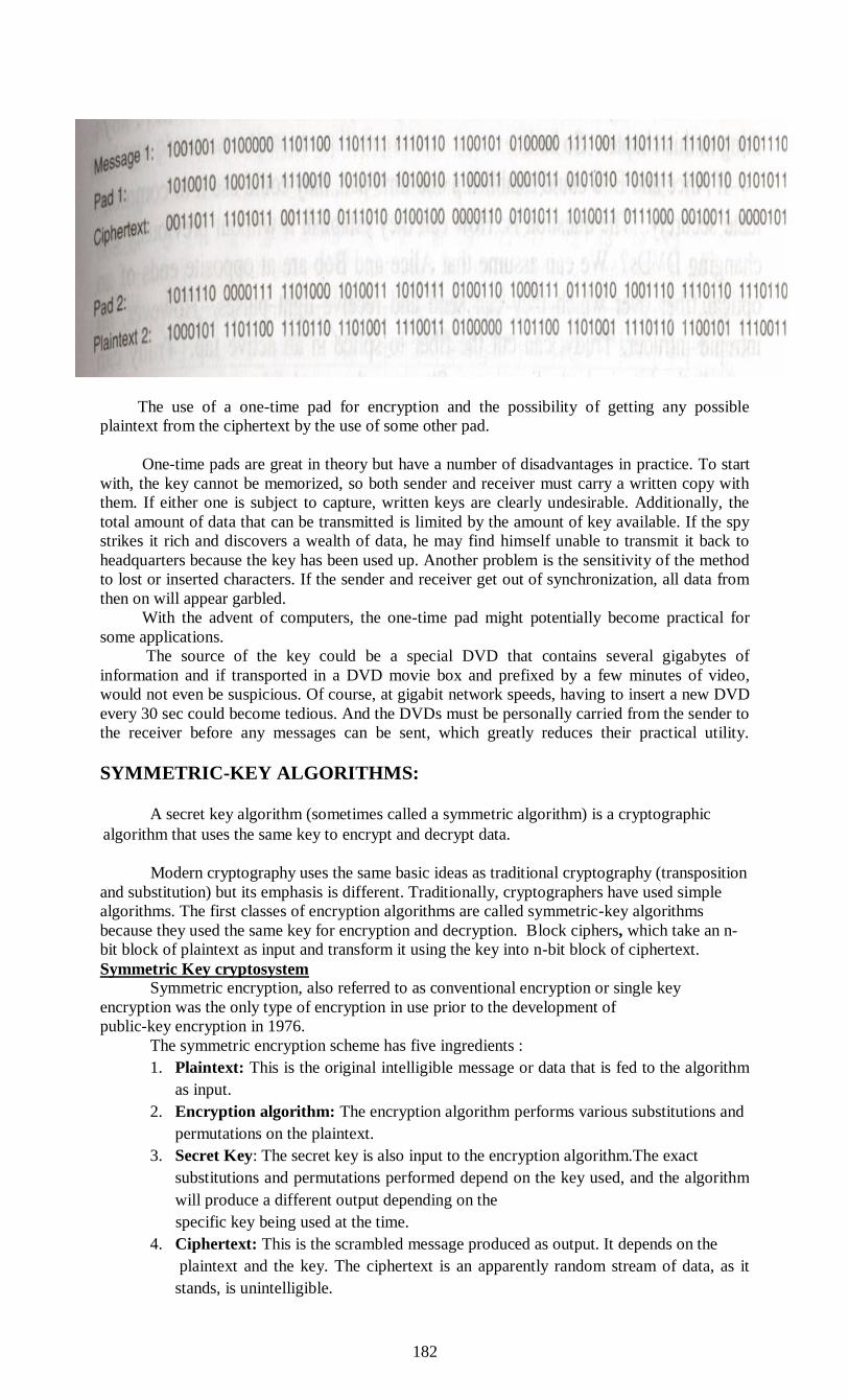
182
The use of a one-time pad for encryption and the possibility of getting any possible
plaintext from the ciphertext by the use of some other pad.
One-time pads are great in theory but have a number of disadvantages in practice. To start
with, the key cannot be memorized, so both sender and receiver must carry a written copy with
them. If either one is subject to capture, written keys are clearly undesirable. Additionally, the
total amount of data that can be transmitted is limited by the amount of key available. If the spy
strikes it rich and discovers a wealth of data, he may find himself unable to transmit it back to
headquarters because the key has been used up. Another problem is the sensitivity of the method
to lost or inserted characters. If the sender and receiver get out of synchronization, all data from
then on will appear garbled.
With the advent of computers, the one-time pad might potentially become practical for
some applications.
The source of the key could be a special DVD that contains several gigabytes of
information and if transported in a DVD movie box and prefixed by a few minutes of video,
would not even be suspicious. Of course, at gigabit network speeds, having to insert a new DVD
every 30 sec could become tedious. And the DVDs must be personally carried from the sender to
the receiver before any messages can be sent, which greatly reduces their practical utility.
SYMMETRIC-KEY ALGORITHMS:
A secret key algorithm (sometimes called a symmetric algorithm) is a cryptographic
algorithm that uses the same key to encrypt and decrypt data.
Modern cryptography uses the same basic ideas as traditional cryptography (transposition
and substitution) but its emphasis is different. Traditionally, cryptographers have used simple
algorithms. The first classes of encryption algorithms are called symmetric-key algorithms
because they used the same key for encryption and decryption. Block ciphers, which take an n-
bit block of plaintext as input and transform it using the key into n-bit block of ciphertext.
Symmetric Key cryptosystem
Symmetric encryption, also referred to as conventional encryption or single key
encryption was the only type of encryption in use prior to the development of
public-key encryption in 1976.
The symmetric encryption scheme has five ingredients :
1. Plaintext: This is the original intelligible message or data that is fed to the algorithm
as input.
2. Encryption algorithm: The encryption algorithm performs various substitutions and
permutations on the plaintext.
3. Secret Key: The secret key is also input to the encryption algorithm.The exact
substitutions and permutations performed depend on the key used, and the algorithm
will produce a different output depending on the
specific key being used at the time.
4. Ciphertext: This is the scrambled message produced as output. It depends on the
plaintext and the key. The ciphertext is an apparently random stream of data, as it
stands, is unintelligible.
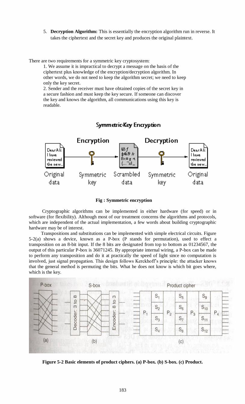
183
5. Decryption Algorithm: This is essentially the encryption algorithm run in reverse. It
takes the ciphertext and the secret key and produces the original plaintext.
There are two requirements for a symmetric key cryptosystem:
1. We assume it is impractical to decrypt a message on the basis of the
ciphertext plus knowledge of the encryption/decryption algorithm. In
other words, we do not need to keep the algorithm secret; we need to keep
only the key secret.
2. Sender and the receiver must have obtained copies of the secret key in
a secure fashion and must keep the key secure. If someone can discover
the key and knows the algorithm, all communications using this key is
readable.
Fig : Symmetric encryption
Cryptographic algorithms can be implemented in either hardware (for speed) or in
software (for flexibility). Although most of our treatment concerns the algorithms and protocols,
which are independent of the actual implementation, a few words about building cryptographic
hardware may be of interest.
Transpositions and substitutions can be implemented with simple electrical circuits. Figure
5-2(a) shows a device, known as a P-box (P stands for permutation), used to effect a
transposition on an 8-bit input. If the 8 bits are designated from top to bottom as 01234567, the
output of this particular P-box is 36071245. By appropriate internal wiring, a P-box can be made
to perform any transposition and do it at practically the speed of light since no computation is
involved, just signal propagation. This design follows Kerckhoff’s principle: the attacker knows
that the general method is permuting the bits. What he does not know is which bit goes where,
which is the key.
Figure 5-2 Basic elements of product ciphers. (a) P-box. (b) S-box. (c) Product.
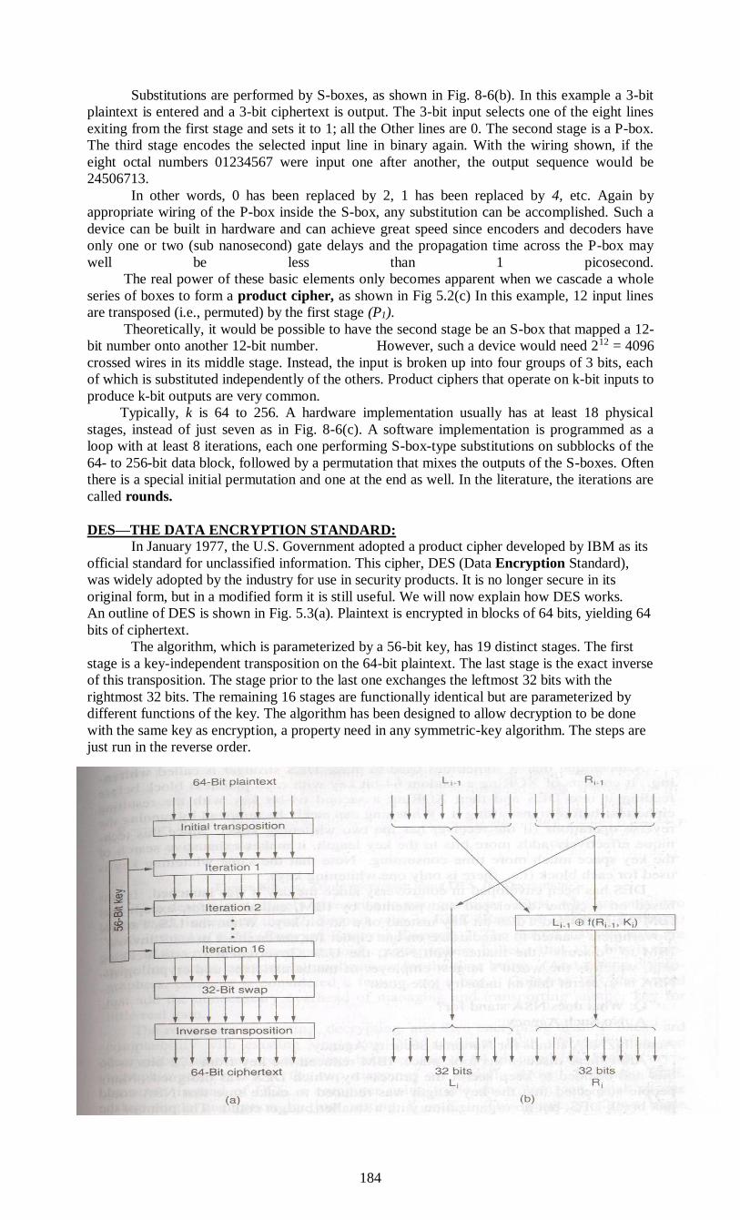
184
Substitutions are performed by S-boxes, as shown in Fig. 8-6(b). In this example a 3-bit
plaintext is entered and a 3-bit ciphertext is output. The 3-bit input selects one of the eight lines
exiting from the first stage and sets it to 1; all the Other lines are 0. The second stage is a P-box.
The third stage encodes the selected input line in binary again. With the wiring shown, if the
eight octal numbers 01234567 were input one after another, the output sequence would be
24506713.
In other words, 0 has been replaced by 2, 1 has been replaced by 4, etc. Again by
appropriate wiring of the P-box inside the S-box, any substitution can be accomplished. Such a
device can be built in hardware and can achieve great speed since encoders and decoders have
only one or two (sub nanosecond) gate delays and the propagation time across the P-box may
well be less than 1 picosecond.
The real power of these basic elements only becomes apparent when we cascade a whole
series of boxes to form a product cipher, as shown in Fig 5.2(c) In this example, 12 input lines
are transposed (i.e., permuted) by the first stage (P1).
Theoretically, it would be possible to have the second stage be an S-box that mapped a 12-
bit number onto another 12-bit number. However, such a device would need 212 = 4096
crossed wires in its middle stage. Instead, the input is broken up into four groups of 3 bits, each
of which is substituted independently of the others. Product ciphers that operate on k-bit inputs to
produce k-bit outputs are very common.
Typically, k is 64 to 256. A hardware implementation usually has at least 18 physical
stages, instead of just seven as in Fig. 8-6(c). A software implementation is programmed as a
loop with at least 8 iterations, each one performing S-box-type substitutions on subblocks of the
64- to 256-bit data block, followed by a permutation that mixes the outputs of the S-boxes. Often
there is a special initial permutation and one at the end as well. In the literature, the iterations are
called rounds.
DES—THE DATA ENCRYPTION STANDARD:
In January 1977, the U.S. Government adopted a product cipher developed by IBM as its
official standard for unclassified information. This cipher, DES (Data Encryption Standard),
was widely adopted by the industry for use in security products. It is no longer secure in its
original form, but in a modified form it is still useful. We will now explain how DES works.
An outline of DES is shown in Fig. 5.3(a). Plaintext is encrypted in blocks of 64 bits, yielding 64
bits of ciphertext.
The algorithm, which is parameterized by a 56-bit key, has 19 distinct stages. The first
stage is a key-independent transposition on the 64-bit plaintext. The last stage is the exact inverse
of this transposition. The stage prior to the last one exchanges the leftmost 32 bits with the
rightmost 32 bits. The remaining 16 stages are functionally identical but are parameterized by
different functions of the key. The algorithm has been designed to allow decryption to be done
with the same key as encryption, a property need in any symmetric-key algorithm. The steps are
just run in the reverse order.

185
Figure 5.3 The data encryption standard. (a) General outline. (b) Detail of one iteration.
The circled + means exclusive OR.
The operation of one of these intermediate stages is illustrated in Fig. 5.3(b). Each stage
takes two 32-bit inputs and produces two 32-bit outputs. The left output is simply a copy of the
right input. The right output is the bitwise XOR of the left input and a function of the right input
and the key for this stage, Ki. All the complexity lies in this function.
The function consists of four steps, carried out in sequence. First, a 48-bit number, E, is
constructed by expanding the 32-bit Ri-1 according to a fixed transposition and duplication rule.
Second, E and Ki are XORed together. This output is then partitioned into eight groups of 6 bits
each, each of which is fed into a different S-box.
Each of the 64 possible inputs to an S-box is mapped onto a 4-bit Output. Finally, these 8 x
4 bits are passed through a P-box. In each of the 16 iterations, a different key is used. Before the
algorithm starts, a 56-bit transposition is applied to the key. Just before each iteration, the key is
partitioned into two 28-bit units, each of which is rotated left by a number of bits dependent on
the iteration number. Ki is derived from this rotated key by applying yet another 56-bit
transposition to it. A different 48-bit subset of the 56 bits is extracted and permuted on each
round.
A technique that is sometimes used to make DES stronger is called whitening. It consists
of XORing a random 64-bit key with each plaintext block before feeding it into DES and then
XORing a second 64-bit key with the resulting ciphertext before transmitting it. Whitening can
easily be removed by running reverse operations (if the receiver has the two whitening keys).
Since this technique effectively adds more bits to the key length, it makes exhaustive search of
the key space much more time consuming. Note that the same whitening key is used for each
block (i.e., there is only one whitening key).
DES has been enveloped in controversy since the day it was launched It was based on a
cipher developed and patented by IBM, called Lucifer, except that IBM’s cipher used a 128-bit
key instead of a 56-bit key. NSA stands for National Security Agency.
IBM reduced the key from 128 bits to 56 bits and decided to keep secret the process by
which DES was designed. Many people suspected that the key length was reduced to make sure
that NSA could just break DES, but no organization with a smaller budget could. The point of
the secret design was supposedly to hide a back door that could make it even easier for NSA to
break DES. When an NSA employee discreetly told IEEE to cancel a planned conference on
cryptography that did not make people any more comfortable.
NSA denied everything. In 1977, two Stanford cryptography researchers, Diffie and
Heliman (1977), designed a machine to break DES and estimated that it could be built for 20
million dollars. Given a small piece of plaintext and matched ciphertext, this machine could find
the key by exhaustive search of the 256-entry key space in under 1 day. Nowadays, such a
machine would cost well under 1 million dollars.
TRIPLE DES:
As early as 1979, IBM realized that the DES key length was too short and7 vised a way
to effectively increase it, using triple encryption (Tuchmandard The method chosen, which has
since been incorporated in International In the 8732, is illustrated in Fig. 8-8. Here two keys and
three stages are used. In the first stage, the plaintext is encrypted using DES in the usual way
with Ki. another second stage, DES is run in decryption mode, using J2 as the key. Final
Year DES encryption is done with K1.
This design immediately gives rise to two questions. First, why are only two keys used,
instead of three? Second, why is EDE (Encrypt Decrypt Encrypt) used, instead of EEE (Encrypt
Encrypt Encrypt)? The reason that two keys are used is that even the most paranoid
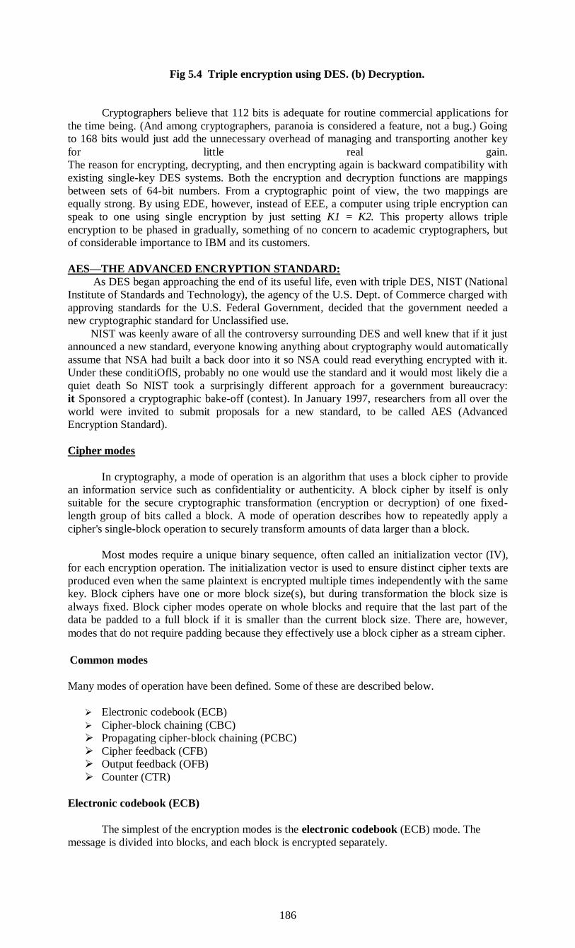
186
Fig 5.4 Triple encryption using DES. (b) Decryption.
Cryptographers believe that 112 bits is adequate for routine commercial applications for
the time being. (And among cryptographers, paranoia is considered a feature, not a bug.) Going
to 168 bits would just add the unnecessary overhead of managing and transporting another key
for little real gain.
The reason for encrypting, decrypting, and then encrypting again is backward compatibility with
existing single-key DES systems. Both the encryption and decryption functions are mappings
between sets of 64-bit numbers. From a cryptographic point of view, the two mappings are
equally strong. By using EDE, however, instead of EEE, a computer using triple encryption can
speak to one using single encryption by just setting K1 = K2. This property allows triple
encryption to be phased in gradually, something of no concern to academic cryptographers, but
of considerable importance to IBM and its customers.
AES—THE ADVANCED ENCRYPTION STANDARD:
As DES began approaching the end of its useful life, even with triple DES, NIST (National
Institute of Standards and Technology), the agency of the U.S. Dept. of Commerce charged with
approving standards for the U.S. Federal Government, decided that the government needed a
new cryptographic standard for Unclassified use.
NIST was keenly aware of all the controversy surrounding DES and well knew that if it just
announced a new standard, everyone knowing anything about cryptography would automatically
assume that NSA had built a back door into it so NSA could read everything encrypted with it.
Under these conditiOflS, probably no one would use the standard and it would most likely die a
quiet death So NIST took a surprisingly different approach for a government bureaucracy:
it Sponsored a cryptographic bake-off (contest). In January 1997, researchers from all over the
world were invited to submit proposals for a new standard, to be called AES (Advanced
Encryption Standard).
Cipher modes
In cryptography, a mode of operation is an algorithm that uses a block cipher to provide
an information service such as confidentiality or authenticity. A block cipher by itself is only
suitable for the secure cryptographic transformation (encryption or decryption) of one fixed-
length group of bits called a block. A mode of operation describes how to repeatedly apply a
cipher's single-block operation to securely transform amounts of data larger than a block.
Most modes require a unique binary sequence, often called an initialization vector (IV),
for each encryption operation. The initialization vector is used to ensure distinct cipher texts are
produced even when the same plaintext is encrypted multiple times independently with the same
key. Block ciphers have one or more block size(s), but during transformation the block size is
always fixed. Block cipher modes operate on whole blocks and require that the last part of the
data be padded to a full block if it is smaller than the current block size. There are, however,
modes that do not require padding because they effectively use a block cipher as a stream cipher.
Common modes
Many modes of operation have been defined. Some of these are described below.
Electronic codebook (ECB)
Cipher-block chaining (CBC)
Propagating cipher-block chaining (PCBC)
Cipher feedback (CFB)
Output feedback (OFB)
Counter (CTR)
Electronic codebook (ECB)
The simplest of the encryption modes is the electronic codebook (ECB) mode. The
message is divided into blocks, and each block is encrypted separately.
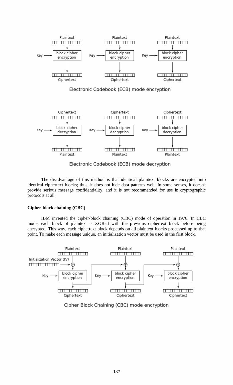
187
The disadvantage of this method is that identical plaintext blocks are encrypted into
identical ciphertext blocks; thus, it does not hide data patterns well. In some senses, it doesn't
provide serious message confidentiality, and it is not recommended for use in cryptographic
protocols at all.
Cipher-block chaining (CBC)
IBM invented the cipher-block chaining (CBC) mode of operation in 1976. In CBC
mode, each block of plaintext is XORed with the previous ciphertext block before being
encrypted. This way, each ciphertext block depends on all plaintext blocks processed up to that
point. To make each message unique, an initialization vector must be used in the first block.
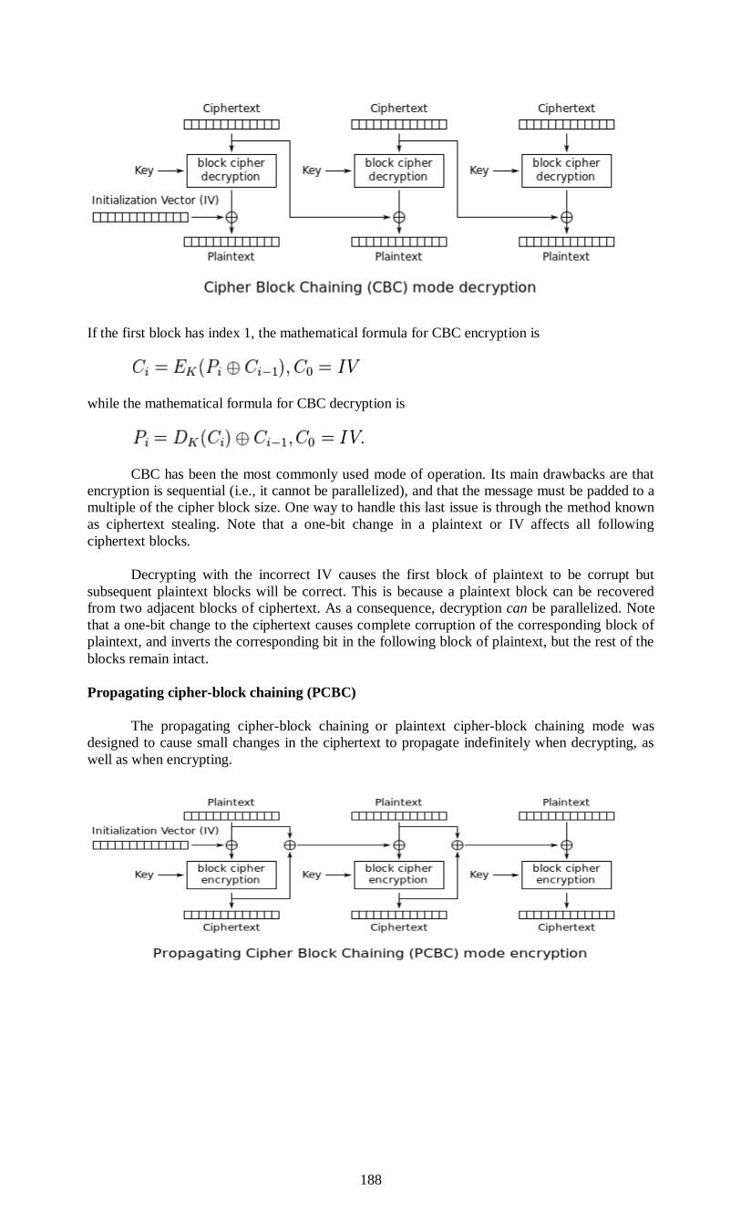
188
If the first block has index 1, the mathematical formula for CBC encryption is
while the mathematical formula for CBC decryption is
CBC has been the most commonly used mode of operation. Its main drawbacks are that
encryption is sequential (i.e., it cannot be parallelized), and that the message must be padded to a
multiple of the cipher block size. One way to handle this last issue is through the method known
as ciphertext stealing. Note that a one-bit change in a plaintext or IV affects all following
ciphertext blocks.
Decrypting with the incorrect IV causes the first block of plaintext to be corrupt but
subsequent plaintext blocks will be correct. This is because a plaintext block can be recovered
from two adjacent blocks of ciphertext. As a consequence, decryption can be parallelized. Note
that a one-bit change to the ciphertext causes complete corruption of the corresponding block of
plaintext, and inverts the corresponding bit in the following block of plaintext, but the rest of the
blocks remain intact.
Propagating cipher-block chaining (PCBC)
The propagating cipher-block chaining or plaintext cipher-block chaining mode was
designed to cause small changes in the ciphertext to propagate indefinitely when decrypting, as
well as when encrypting.

189
Encryption and decryption algorithms are as follows:
PCBC is used in Kerberos v4 and WASTE, most notably, but otherwise is not common.
On a message encrypted in PCBC mode, if two adjacent ciphertext blocks are exchanged, this
does not affect the decryption of subsequent blocks. For this reason, PCBC is not used in
Kerberos v5.
Cipher feedback (CFB)
The cipher feedback (CFB) mode, a close relative of CBC, makes a block cipher into a
self-synchronizing stream cipher. Operation is very similar; in particular, CFB decryption is
almost identical to CBC encryption performed in reverse:
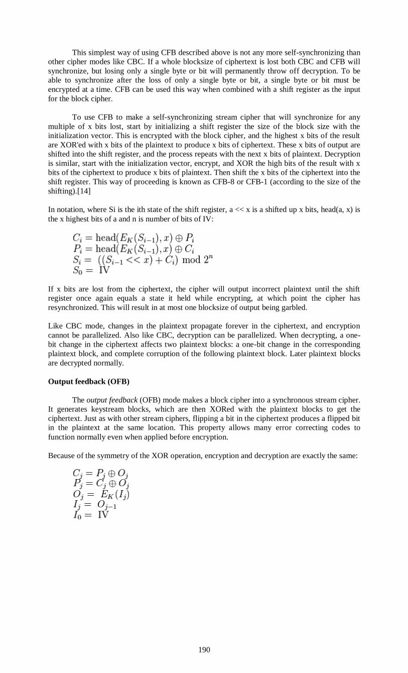
190
This simplest way of using CFB described above is not any more self-synchronizing than
other cipher modes like CBC. If a whole blocksize of ciphertext is lost both CBC and CFB will
synchronize, but losing only a single byte or bit will permanently throw off decryption. To be
able to synchronize after the loss of only a single byte or bit, a single byte or bit must be
encrypted at a time. CFB can be used this way when combined with a shift register as the input
for the block cipher.
To use CFB to make a self-synchronizing stream cipher that will synchronize for any
multiple of x bits lost, start by initializing a shift register the size of the block size with the
initialization vector. This is encrypted with the block cipher, and the highest x bits of the result
are XOR'ed with x bits of the plaintext to produce x bits of ciphertext. These x bits of output are
shifted into the shift register, and the process repeats with the next x bits of plaintext. Decryption
is similar, start with the initialization vector, encrypt, and XOR the high bits of the result with x
bits of the ciphertext to produce x bits of plaintext. Then shift the x bits of the ciphertext into the
shift register. This way of proceeding is known as CFB-8 or CFB-1 (according to the size of the
shifting).[14]
In notation, where Si is the ith state of the shift register, a << x is a shifted up x bits, head(a, x) is
the x highest bits of a and n is number of bits of IV:
If x bits are lost from the ciphertext, the cipher will output incorrect plaintext until the shift
register once again equals a state it held while encrypting, at which point the cipher has
resynchronized. This will result in at most one blocksize of output being garbled.
Like CBC mode, changes in the plaintext propagate forever in the ciphertext, and encryption
cannot be parallelized. Also like CBC, decryption can be parallelized. When decrypting, a one-
bit change in the ciphertext affects two plaintext blocks: a one-bit change in the corresponding
plaintext block, and complete corruption of the following plaintext block. Later plaintext blocks
are decrypted normally.
Output feedback (OFB)
The output feedback (OFB) mode makes a block cipher into a synchronous stream cipher.
It generates keystream blocks, which are then XORed with the plaintext blocks to get the
ciphertext. Just as with other stream ciphers, flipping a bit in the ciphertext produces a flipped bit
in the plaintext at the same location. This property allows many error correcting codes to
function normally even when applied before encryption.
Because of the symmetry of the XOR operation, encryption and decryption are exactly the same:
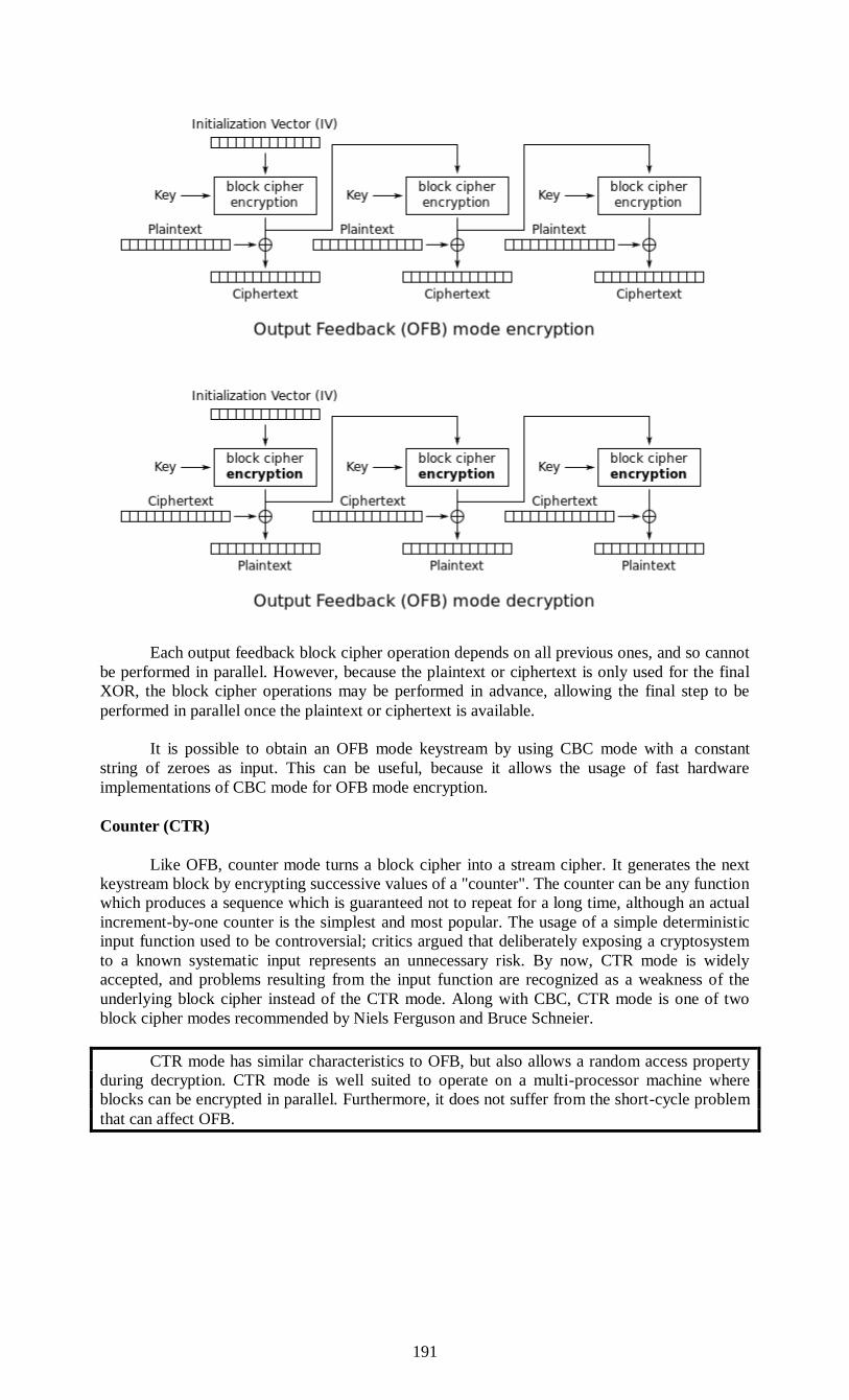
191
Each output feedback block cipher operation depends on all previous ones, and so cannot
be performed in parallel. However, because the plaintext or ciphertext is only used for the final
XOR, the block cipher operations may be performed in advance, allowing the final step to be
performed in parallel once the plaintext or ciphertext is available.
It is possible to obtain an OFB mode keystream by using CBC mode with a constant
string of zeroes as input. This can be useful, because it allows the usage of fast hardware
implementations of CBC mode for OFB mode encryption.
Counter (CTR)
Like OFB, counter mode turns a block cipher into a stream cipher. It generates the next
keystream block by encrypting successive values of a "counter". The counter can be any function
which produces a sequence which is guaranteed not to repeat for a long time, although an actual
increment-by-one counter is the simplest and most popular. The usage of a simple deterministic
input function used to be controversial; critics argued that deliberately exposing a cryptosystem
to a known systematic input represents an unnecessary risk. By now, CTR mode is widely
accepted, and problems resulting from the input function are recognized as a weakness of the
underlying block cipher instead of the CTR mode. Along with CBC, CTR mode is one of two
block cipher modes recommended by Niels Ferguson and Bruce Schneier.
CTR mode has similar characteristics to OFB, but also allows a random access property
during decryption. CTR mode is well suited to operate on a multi-processor machine where
blocks can be encrypted in parallel. Furthermore, it does not suffer from the short-cycle problem
that can affect OFB.
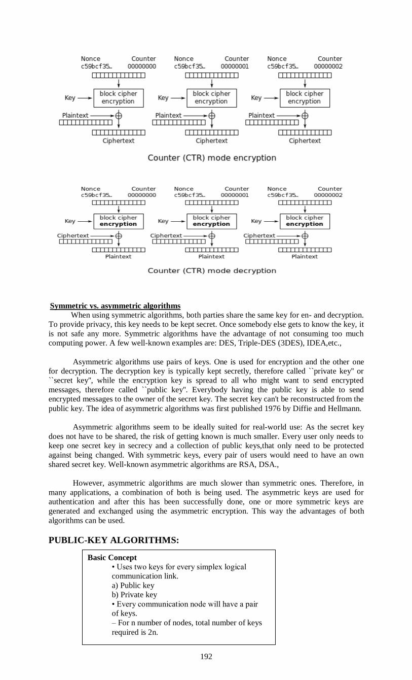
192
Symmetric vs. asymmetric algorithms
When using symmetric algorithms, both parties share the same key for en- and decryption.
To provide privacy, this key needs to be kept secret. Once somebody else gets to know the key, it
is not safe any more. Symmetric algorithms have the advantage of not consuming too much
computing power. A few well-known examples are: DES, Triple-DES (3DES), IDEA,etc.,
Asymmetric algorithms use pairs of keys. One is used for encryption and the other one
for decryption. The decryption key is typically kept secretly, therefore called ``private key'' or
``secret key'', while the encryption key is spread to all who might want to send encrypted
messages, therefore called ``public key''. Everybody having the public key is able to send
encrypted messages to the owner of the secret key. The secret key can't be reconstructed from the
public key. The idea of asymmetric algorithms was first published 1976 by Diffie and Hellmann.
Asymmetric algorithms seem to be ideally suited for real-world use: As the secret key
does not have to be shared, the risk of getting known is much smaller. Every user only needs to
keep one secret key in secrecy and a collection of public keys,that only need to be protected
against being changed. With symmetric keys, every pair of users would need to have an own
shared secret key. Well-known asymmetric algorithms are RSA, DSA.,
However, asymmetric algorithms are much slower than symmetric ones. Therefore, in
many applications, a combination of both is being used. The asymmetric keys are used for
authentication and after this has been successfully done, one or more symmetric keys are
generated and exchanged using the asymmetric encryption. This way the advantages of both
algorithms can be used.
PUBLIC-KEY ALGORITHMS:
Basic Concept
• Uses two keys for every simplex logical
communication link.
a) Public key
b) Private key
• Every communication node will have a pair
of keys.
– For n number of nodes, total number of keys
required is 2n.

193
Public-key cryptography, also known as asymmetric cryptography, is a class of
cryptographic algorithms which requires two separate keys, one of which is secret (or private)
and one of which is public. Although different, the two parts of this key pair are mathematically
linked. The public key is used to encrypt plaintext or to verify a digital signature; whereas the
private key is used to decrypt ciphertext or to create a digital signature. The term "asymmetric"
stems from the use of different keys to perform these opposite functions, each the inverse of the
other – as contrasted with conventional ("symmetric") cryptography which relies on the same
key to perform both.
Public-key algorithms are based on mathematical problems which currently admit no
efficient solution that are inherent in certain integer factorization, discrete logarithm, and elliptic
curve relationships. It is computationally easy for a user to generate their own public and private
key-pair and to use them for encryption and decryption. The strength lies in the fact that it is
"impossible" (computationally infeasible) for a properly generated private key to be determined
from its corresponding public key.
Thus the public key may be published without compromising security, whereas the
private key must not be revealed to anyone not authorized to read messages or perform digital
signatures. Public key algorithms, unlike symmetric key algorithms, do not require a secure
initial exchange of one (or more) secret keys between the parties.
Message authentication involves processing a message with a private key to produce a
digital signature. Thereafter anyone can verify this signature by processing the signature value
with the signer's corresponding public key and comparing that result with the message. Success
confirms the message is unmodified since it was signed, and – presuming the signer's private key
has remained secret to the signer – that the signer, and no one else, intentionally performed the
signature operation. In practice, typically only a hash or digest of the message, and not the
message itself, is encrypted as the signature.
Public-key algorithms are fundamental security ingredients in cryptosystems,
applications and protocols. They underpin various Internet standards, such as Transport Layer
Security (TLS), PGP, and GPG. Some public key algorithms provide key distribution and
secrecy (e.g., Diffie–Hellman key exchange), some provide digital signatures (e.g., Digital
Signature Algorithm), and some provide both (e.g., RSA).
Public-key cryptography finds application in, amongst others, the IT security discipline
information security. Information security (IS) is concerned with all aspects of protecting
electronic information assets against security threats.[1] Public-key cryptography is used as a
method of assuring the confidentiality, authenticity and non-repudiability of electronic
communications and data storage.
Symmetric Encryption: Historically, encryptions algorithms have primarily been of a
type known as symmetric. This means that the same key is used to encrypt and decrypt the file).
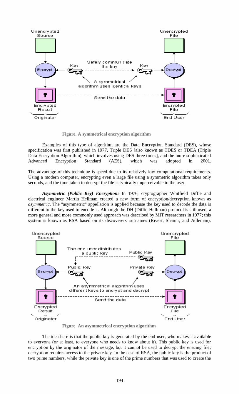
194
Figure. A symmetrical encryption algorithm
Examples of this type of algorithm are the Data Encryption Standard (DES), whose
specification was first published in 1977, Triple DES [also known as TDES or TDEA (Triple
Data Encryption Algorithm), which involves using DES three times], and the more sophisticated
Advanced Encryption Standard (AES), which was adopted in 2001.
The advantage of this technique is speed due to its relatively low computational requirements.
Using a modern computer, encrypting even a large file using a symmetric algorithm takes only
seconds, and the time taken to decrypt the file is typically unperceivable to the user.
Asymmetric (Public Key) Encryption: In 1976, cryptographer Whitfield Diffie and
electrical engineer Martin Hellman created a new form of encryption/decryption known as
asymmetric. The "asymmetric" appellation is applied because the key used to decode the data is
different to the key used to encode it. Although the DH (Diffie-Hellman) protocol is still used, a
more general and more commonly used approach was described by MIT researchers in 1977; this
system is known as RSA based on its discoverers' surnames (Rivest, Shamir, and Adleman).
Figure An asymmetrical encryption algorithm
The idea here is that the public key is generated by the end-user, who makes it available
to everyone (or at least, to everyone who needs to know about it). This public key is used for
encryption by the originator of the message, but it cannot be used to decrypt the ensuing file;
decryption requires access to the private key. In the case of RSA, the public key is the product of
two prime numbers, while the private key is one of the prime numbers that was used to create the
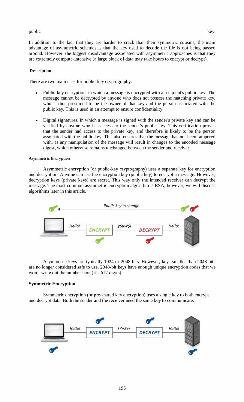
195
public key.
In addition to the fact that they are harder to crack than their symmetric cousins, the main
advantage of asymmetric schemes is that the key used to decode the file is not being passed
around. However, the biggest disadvantage associated with asymmetric approaches is that they
are extremely compute-intensive (a large block of data may take hours to encrypt or decrypt).
Description
There are two main uses for public-key cryptography:
Public-key encryption, in which a message is encrypted with a recipient's public key. The
message cannot be decrypted by anyone who does not possess the matching private key,
who is thus presumed to be the owner of that key and the person associated with the
public key. This is used in an attempt to ensure confidentiality.
Digital signatures, in which a message is signed with the sender's private key and can be
verified by anyone who has access to the sender's public key. This verification proves
that the sender had access to the private key, and therefore is likely to be the person
associated with the public key. This also ensures that the message has not been tampered
with, as any manipulation of the message will result in changes to the encoded message
digest, which otherwise remains unchanged between the sender and receiver.
Asymmetric Encryption
Asymmetric encryption (or public-key cryptography) uses a separate key for encryption
and decryption. Anyone can use the encryption key (public key) to encrypt a message. However,
decryption keys (private keys) are secret. This way only the intended receiver can decrypt the
message. The most common asymmetric encryption algorithm is RSA; however, we will discuss
algorithms later in this article.
Asymmetric keys are typically 1024 or 2048 bits. However, keys smaller than 2048 bits
are no longer considered safe to use. 2048-bit keys have enough unique encryption codes that we
won’t write out the number here (it’s 617 digits).
Symmetric Encryption
Symmetric encryption (or pre-shared key encryption) uses a single key to both encrypt
and decrypt data. Both the sender and the receiver need the same key to communicate.

196
Symmetric key sizes are typically 128 or 256 bits—the larger the key size, the harder the key is
to crack. For example, a 128-bit key has 340,282,366,920,938,463,463,374,607,431,768,211,456
encryption code possibilities. As can imagine, a ‘brute force’ attack (in which an attacker tries
every possible key until they find the right one) would take quite a bit of time to break a 128-bit
key.
Whether a 128-bit or 256-bit key is used depends on the encryption capabilities of both the
server and the client software. SSL Certificates do not dictate what key size is used.
Cryptologists always took for gran that the encryption key and decryption key were the
same (or easily derived fr ed one another). But the key had to be distributed to all users of the
system. Thus seemed as if there was an inherent built-in problem. Keys had to be protece from
theft, but they also had to be distributed, so they could not just be locked u in a bank vault. p
The first requirement says that if we apply D to an encrypted message, E(P), we get the
original plaintext message, P, back. Without this property, the legitimate receiver could not
decrypt the ciphertext.
The second requirement speaks for itself. The third requirement is needed because, as we shall
see in a moment, intruders may experiment with the algorithm to their hearts’ content. Under
these conditions, there is no reason that the encryption key cannot be made public.
The method works like this. A person, say, Alice, wanting to receive secret messages, first
devises two algorithms meeting the above requirements. The encryption algorithm and Alice’s
key are then made public, hence the name public key cryptography. Alice might put her public
key on her home page on the Web, for example. We will use the notation EA to mean the
encryption algorithm parameterized by Alice’s public key. Similarly, the (secret) decryption
algorithm parameterized by Alice’s private key is DA. Bob does the same thing, publlclzing\ EB
but keeping DB secret.
Now let us see if we can solve the problem of establishing a secure chanfle between Alice
and Bob, who have never had any previous contact. Both Alice S encryption key, EA, and Bob’s
encryption key, EB, are assumed to be in publiClY readable files. Now Alice takes her first
message, P, computes E8(P), and sen it to Bob. Bob then decrypts it by applying his secret key
D8 [i.e., he computeS D8(E8(P)) =P]. No one else can read the encrypted message, E8(P),
becaUs the encryption system is assumed strong and because it is too difficult to derive D from
the publicly known EB. To send a reply, R, Bob transmits EA(R). Alice and Bob can now
communicate securely.
A note on terminology is perhaps useful here. Public-key cryptography reuires each user to have
two keys: a public key, used by the entire world for enrypting messages to be sent to that user,
and a private key, which the user needs for deciyptmg messages.
RSA :
RSA is one of the first practicable public-key cryptosystems and is widely used for secure
data transmission. In such a cryptosystem, the encryption key is public and differs from the
decryption key which is kept secret. In RSA, this asymmetry is based on the practical difficulty
of factoring the product of two large prime numbers, the factoring problem. RSA stands for Ron
Rivest, Adi Shamir and Leonard Adleman, who first publicly described the algorithm in 1977.
Clifford Cocks, an English mathematician, had developed an equivalent system in 1973, but it
wasn't declassified until 1997.
The RSA algorithm — named after Ron Rivest,
Adi Shamir, and Leonard Adleman — is based
on a property of positive integers that we describe
below.
When n is a product of two primes, in arithmetic
operations modulo n, the exponents behave
modulo the totient _(n) of n.
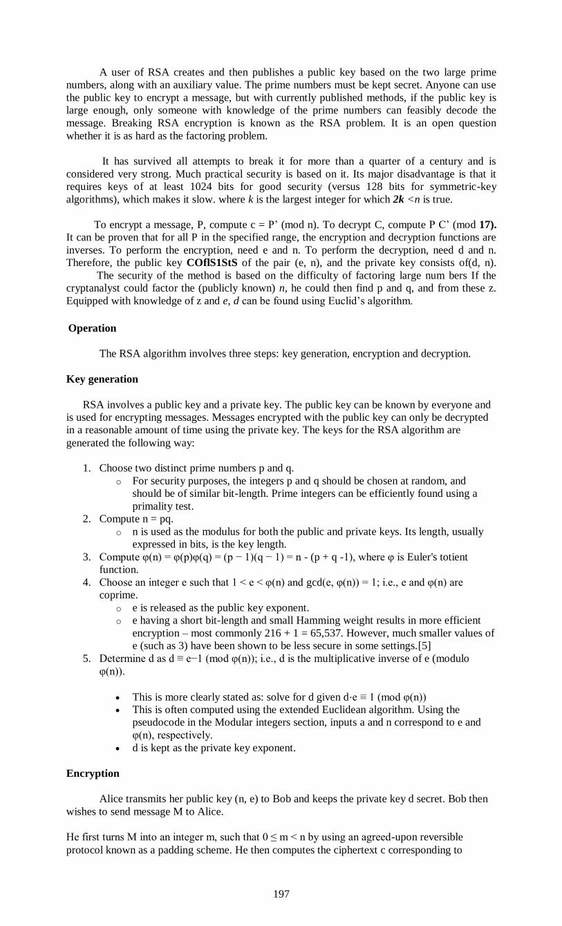
197
A user of RSA creates and then publishes a public key based on the two large prime
numbers, along with an auxiliary value. The prime numbers must be kept secret. Anyone can use
the public key to encrypt a message, but with currently published methods, if the public key is
large enough, only someone with knowledge of the prime numbers can feasibly decode the
message. Breaking RSA encryption is known as the RSA problem. It is an open question
whether it is as hard as the factoring problem.
It has survived all attempts to break it for more than a quarter of a century and is
considered very strong. Much practical security is based on it. Its major disadvantage is that it
requires keys of at least 1024 bits for good security (versus 128 bits for symmetric-key
algorithms), which makes it slow. where k is the largest integer for which 2k <n is true.
To encrypt a message, P, compute c = P’ (mod n). To decrypt C, compute P C’ (mod 17).
It can be proven that for all P in the specified range, the encryption and decryption functions are
inverses. To perform the encryption, need e and n. To perform the decryption, need d and n.
Therefore, the public key COflS1StS of the pair (e, n), and the private key consists of(d, n).
The security of the method is based on the difficulty of factoring large num bers If the
cryptanalyst could factor the (publicly known) n, he could then find p and q, and from these z.
Equipped with knowledge of z and e, d can be found using Euclid’s algorithm.
Operation
The RSA algorithm involves three steps: key generation, encryption and decryption.
Key generation
RSA involves a public key and a private key. The public key can be known by everyone and
is used for encrypting messages. Messages encrypted with the public key can only be decrypted
in a reasonable amount of time using the private key. The keys for the RSA algorithm are
generated the following way:
1. Choose two distinct prime numbers p and q.
o For security purposes, the integers p and q should be chosen at random, and
should be of similar bit-length. Prime integers can be efficiently found using a
primality test.
2. Compute n = pq.
o n is used as the modulus for both the public and private keys. Its length, usually
expressed in bits, is the key length.
3. Compute φ(n) = φ(p)φ(q) = (p − 1)(q − 1) = n - (p + q -1), where φ is Euler's totient
function.
4. Choose an integer e such that 1 < e < φ(n) and gcd(e, φ(n)) = 1; i.e., e and φ(n) are
coprime.
o e is released as the public key exponent.
o e having a short bit-length and small Hamming weight results in more efficient
encryption – most commonly 216 + 1 = 65,537. However, much smaller values of
e (such as 3) have been shown to be less secure in some settings.[5]
5. Determine d as d ≡ e−1 (mod φ(n)); i.e., d is the multiplicative inverse of e (modulo
φ(n)).
This is more clearly stated as: solve for d given d⋅e ≡ 1 (mod φ(n))
This is often computed using the extended Euclidean algorithm. Using the
pseudocode in the Modular integers section, inputs a and n correspond to e and
φ(n), respectively.
d is kept as the private key exponent.
Encryption
Alice transmits her public key (n, e) to Bob and keeps the private key d secret. Bob then
wishes to send message M to Alice.
He first turns M into an integer m, such that 0 ≤ m < n by using an agreed-upon reversible
protocol known as a padding scheme. He then computes the ciphertext c corresponding to
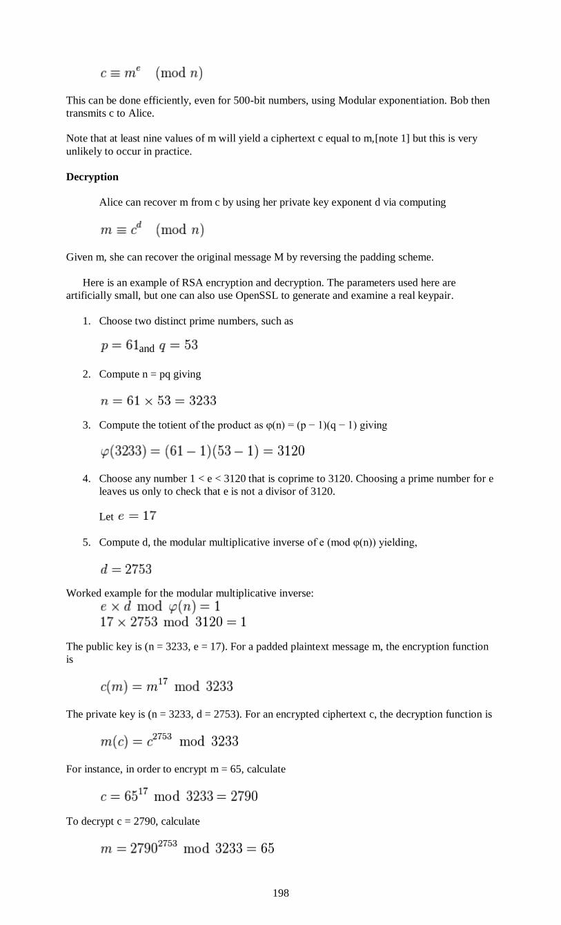
198
This can be done efficiently, even for 500-bit numbers, using Modular exponentiation. Bob then
transmits c to Alice.
Note that at least nine values of m will yield a ciphertext c equal to m,[note 1] but this is very
unlikely to occur in practice.
Decryption
Alice can recover m from c by using her private key exponent d via computing
Given m, she can recover the original message M by reversing the padding scheme.
Here is an example of RSA encryption and decryption. The parameters used here are
artificially small, but one can also use OpenSSL to generate and examine a real keypair.
1. Choose two distinct prime numbers, such as
and
2. Compute n = pq giving
3. Compute the totient of the product as φ(n) = (p − 1)(q − 1) giving
4. Choose any number 1 < e < 3120 that is coprime to 3120. Choosing a prime number for e
leaves us only to check that e is not a divisor of 3120.
Let
5. Compute d, the modular multiplicative inverse of e (mod φ(n)) yielding,
Worked example for the modular multiplicative inverse:
The public key is (n = 3233, e = 17). For a padded plaintext message m, the encryption function
is
The private key is (n = 3233, d = 2753). For an encrypted ciphertext c, the decryption function is
For instance, in order to encrypt m = 65, calculate
To decrypt c = 2790, calculate
199
Other Public-Key Algorithms:
Although RSA is widely used, it is by no means the only pubiic-key algorithm wn. The
first public-key algorithm was the knapsack algorithm (Merkie and IJellma1 1978). The idea
here is that someone owns a large number of objects, each with a different weight. The owner
encodes the message by secretly selecting a subset of the objects and placing them in the
knapsack.
The total weight of the objects in the knapsack is made public, as is the list of all
possible objects. The list of objects in the knapsack is kept secret. With certain additional
restrictions, the problem. of figuring out a possible list of objects with the given weight was
thought to be computationally infeasible and formed the basis of the public- key algorithm. The
algorithm’s inventor, Ralph Merkie, was quite sure that this algorithm could not be broken, so he
offered a $100 reward to anyone who could break it. Adi Shamir (the “S” in RSA) promptly
broke it and collected the reward.
Undeterred, Merkle strengthened the algorithm and offered a $1000 reward to anyone
who could break the new one. Ronald Rivest (the “R” in RSA) promptly broke the new one and
collected the reward. Merkie did not dare offer $10,000 for the next version, so “A” (Leonard
Adleman) was out of luck. Nevertheless, the knapsack algorithm is not considered secure and is
not used in practice any more.
Other public-key schemes are based on the difficulty of computing discrete logarithms.
Algorithms that use this principle have been invented by El Gamal (1985) and Schnorr (1991).
A few other schemes exist, such as those based on elliptic curves (Menezes and Varistone,
1993), but the two major categories are those based on the difficulty of factoring large numbers
and computing discrete logarithms modulo a large prime. These problems are thought to be
genuinely difficult to solve—mathematicians have been working on them for many years without
any great breakthroughs.
DIGITALSIGNATURES
A digital signature is a mathematical scheme for demonstrating the authenticity of a
digital message or document. A valid digital signature gives a recipient reason to believe that the
message was created by a known sender, such that the sender cannot deny having sent the
message (authentication and non-repudiation) and that the message was not altered in transit
(integrity). Digital signatures are commonly used for software distribution, financial transactions,
and in other cases
The authenticity of many legal, financial, and other documents is determined by the
presence or absence of an authorized handwritten signature. And photocopies do not count. For
computerized message systems to replace the physical transport of paper and ink documents, a
method must be found to allow documents to be signed in an unforgeable way.
The problem of devising a replacement for handwritten signatures is a difficult one. Basically,
what is needed is a system by which one party can send a Signed message to another party in
such a way that the following conditions hold:
1. The receiver can verify the claimed identity of the sender.
2. The sender cannot later repudiate the contents of the message,
3. The receiver cannot possibly have concocted the message
A digital signature is basically a way to ensure that an electronic document (e-mail,
spreadsheet, text file, etc.) is authentic. Authentic means that know who created the document
and know that it has not been altered in any way since that person created it.
Digital signatures rely on certain types of encryption to ensure authentication.
Encryption is the process of taking all the data that one computer is sending to another and
encoding it into a form that only the other computer will be able to decode. Authentication is the
process of verifying that information is coming from a trusted source. These two processes work
hand in hand for digital signatures.
There are several ways to authenticate a person or information on a computer:
200
Password - The use of a user name and password provide the most common form of
authentication. enter name and password when prompted by the computer. It checks the pair
against a secure file to confirm. If either the name or password do not match, then are not
allowed further access.
Checksum - Probably one of the oldest methods of ensuring that data is correct, checksums also
provide a form of authentication since an invalid checksum suggests that the data has been
compromised in some fashion. A checksum is determined in one of two ways. Let's say the
checksum of a packet is 1 byte long, which means it can have a maximum value of 255. If the
sum of the other bytes in the packet is 255 or less, then the checksum contains that exact value.
However, if the sum of the other bytes is more than 255, then the checksum is the remainder of
the total value after it has been divided by 256. Look at this example:
Byte 1 = 212
Byte 2 = 232
Byte 3 = 54
Byte 4 = 135
Byte 5 = 244
Byte 6 = 15
Byte 7 = 179
Byte 8 = 80
Total = 1151. 1151 divided by 256 equals 4.496 (round to 4). Multiply 4 X 256 which
equals 1024. 1151 minus 1024 equals checksum of 127
CRC (Cyclic Redundancy Check) - CRCs are similar in concept to checksums but they use
polynomial division to determine the value of the CRC, which is usually 16 or 32 bits in length.
The good thing about CRC is that it is very accurate. If a single bit is incorrect, the CRC value
will not match up. Both checksum and CRC are good for preventing random errors in
transmission, but provide little protection from an intentional attack on data. The encryption
techniques below are much more secure.
Private key encryption -Private key means that each computer has a secret key (code) that it
can use to encrypt a packet of information before it is sent over the network to the other
computer. Private key requires that know which computers will talk to each other and install the
key on each one. Private key encryption is essentially the same as a secret code that the two
computers must each know in order to decode the information. The code would provide the key
to decoding the message. Think of it like this. create a coded message to send to a friend where
each letter is substituted by the letter that is second from it. So "A" becomes "C" and "B"
becomes "D". have already told a trusted friend that the code is "Shift by 2". friend gets the
message and decodes it. Anyone else who sees the message will only see nonsense.
Public key encryption - Public key encryption uses a combination of a private key and a
public key. The private key is known only to computer while the public key is given by
computer to any computer that wants to communicate securely with it. To decode an encrypted
message, a computer must use the public key provided by the originating computer and it's own
private key.
The key is based on a hash value. This is a value that is computed from a base input number
using a hashing algorithm. The important thing about a hash value is that it is nearly impossible
to derive the original input number without knowing the data used to create the hash value.
Here's a simple example:
Input number 10667Hashing Algorithm = Input # x 143Hash Value = 1525381
Public key encryption is much more complex than this example but that is the basic idea.
Public keys generally use complex algorithms and very large hash values for encrypting: 40-bit
or even 128-bit numbers. A 128-bit number has a possible 2128 different combinations. That's as
many combinations as there are water molecules in 2.7 million olympic size swimming pools.
Even the tiniest water droplet can image has billions and billions of water molecules in it!
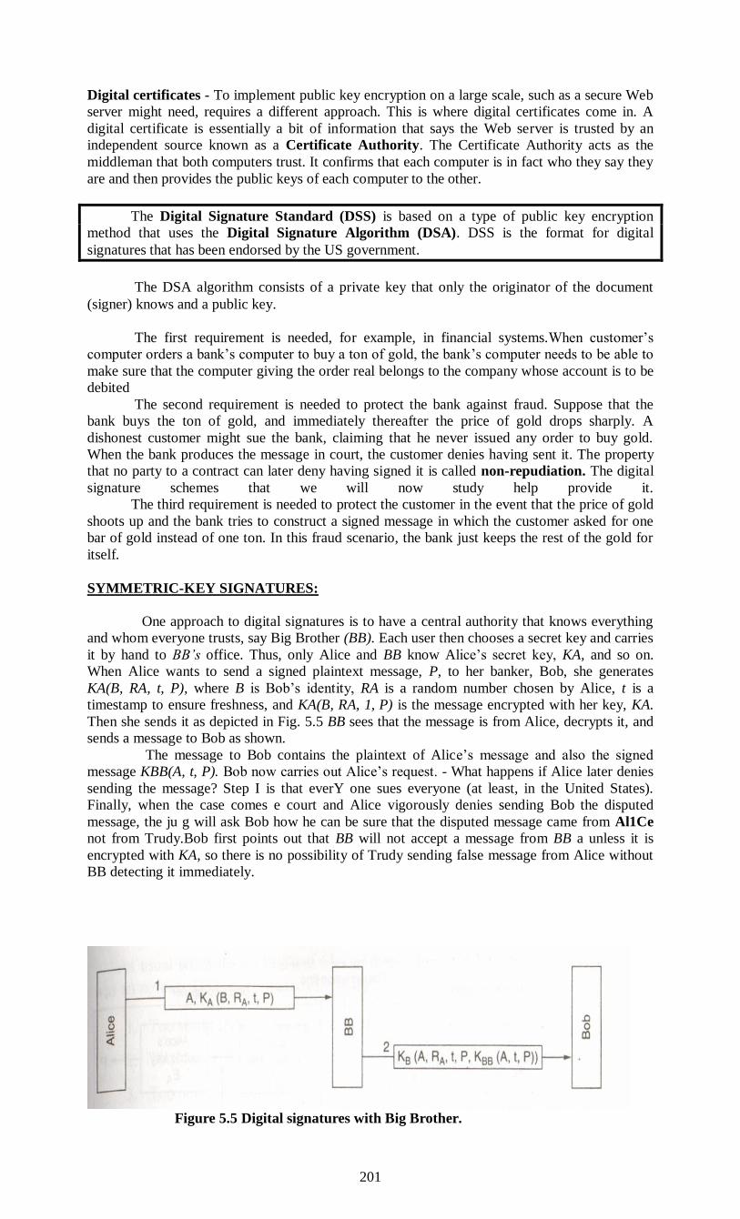
201
Digital certificates - To implement public key encryption on a large scale, such as a secure Web
server might need, requires a different approach. This is where digital certificates come in. A
digital certificate is essentially a bit of information that says the Web server is trusted by an
independent source known as a Certificate Authority. The Certificate Authority acts as the
middleman that both computers trust. It confirms that each computer is in fact who they say they
are and then provides the public keys of each computer to the other.
The Digital Signature Standard (DSS) is based on a type of public key encryption
method that uses the Digital Signature Algorithm (DSA). DSS is the format for digital
signatures that has been endorsed by the US government.
The DSA algorithm consists of a private key that only the originator of the document
(signer) knows and a public key.
The first requirement is needed, for example, in financial systems.When customer’s
computer orders a bank’s computer to buy a ton of gold, the bank’s computer needs to be able to
make sure that the computer giving the order real belongs to the company whose account is to be
debited
The second requirement is needed to protect the bank against fraud. Suppose that the
bank buys the ton of gold, and immediately thereafter the price of gold drops sharply. A
dishonest customer might sue the bank, claiming that he never issued any order to buy gold.
When the bank produces the message in court, the customer denies having sent it. The property
that no party to a contract can later deny having signed it is called non-repudiation. The digital
signature schemes that we will now study help provide it.
The third requirement is needed to protect the customer in the event that the price of gold
shoots up and the bank tries to construct a signed message in which the customer asked for one
bar of gold instead of one ton. In this fraud scenario, the bank just keeps the rest of the gold for
itself.
SYMMETRIC-KEY SIGNATURES:
One approach to digital signatures is to have a central authority that knows everything
and whom everyone trusts, say Big Brother (BB). Each user then chooses a secret key and carries
it by hand to BB’s office. Thus, only Alice and BB know Alice’s secret key, KA, and so on.
When Alice wants to send a signed plaintext message, P, to her banker, Bob, she generates
KA(B, RA, t, P), where B is Bob’s identity, RA is a random number chosen by Alice, t is a
timestamp to ensure freshness, and KA(B, RA, 1, P) is the message encrypted with her key, KA.
Then she sends it as depicted in Fig. 5.5 BB sees that the message is from Alice, decrypts it, and
sends a message to Bob as shown.
The message to Bob contains the plaintext of Alice’s message and also the signed
message KBB(A, t, P). Bob now carries out Alice’s request. - What happens if Alice later denies
sending the message? Step I is that everY one sues everyone (at least, in the United States).
Finally, when the case comes e court and Alice vigorously denies sending Bob the disputed
message, the ju g will ask Bob how he can be sure that the disputed message came from Al1Ce
not from Trudy.Bob first points out that BB will not accept a message from BB a unless it is
encrypted with KA, so there is no possibility of Trudy sending false message from Alice without
BB detecting it immediately.
Figure 5.5 Digital signatures with Big Brother.
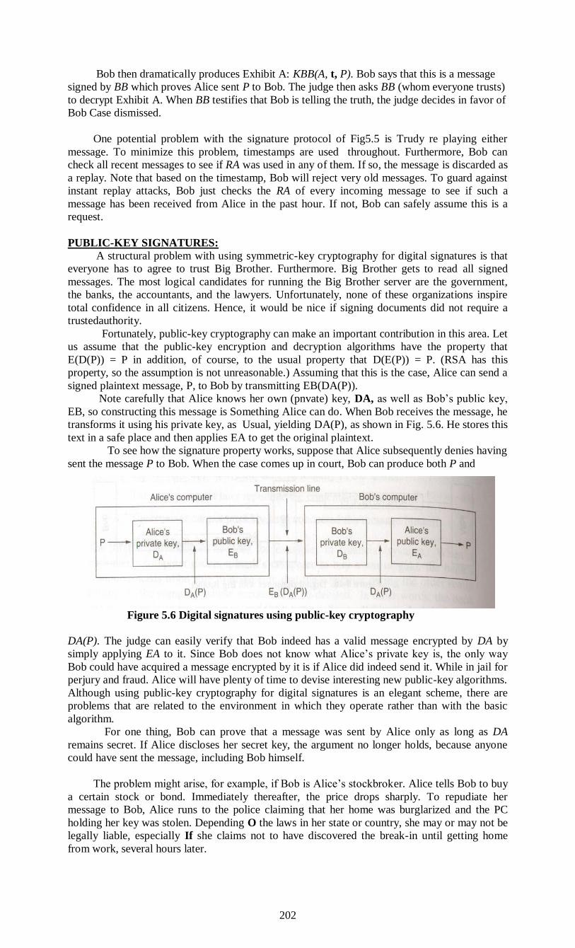
202
Bob then dramatically produces Exhibit A: KBB(A, t, P). Bob says that this is a message
signed by BB which proves Alice sent P to Bob. The judge then asks BB (whom everyone trusts)
to decrypt Exhibit A. When BB testifies that Bob is telling the truth, the judge decides in favor of
Bob Case dismissed.
One potential problem with the signature protocol of Fig5.5 is Trudy re playing either
message. To minimize this problem, timestamps are used throughout. Furthermore, Bob can
check all recent messages to see if RA was used in any of them. If so, the message is discarded as
a replay. Note that based on the timestamp, Bob will reject very old messages. To guard against
instant replay attacks, Bob just checks the RA of every incoming message to see if such a
message has been received from Alice in the past hour. If not, Bob can safely assume this is a
request.
PUBLIC-KEY SIGNATURES:
A structural problem with using symmetric-key cryptography for digital signatures is that
everyone has to agree to trust Big Brother. Furthermore. Big Brother gets to read all signed
messages. The most logical candidates for running the Big Brother server are the government,
the banks, the accountants, and the lawyers. Unfortunately, none of these organizations inspire
total confidence in all citizens. Hence, it would be nice if signing documents did not require a
trustedauthority.
Fortunately, public-key cryptography can make an important contribution in this area. Let
us assume that the public-key encryption and decryption algorithms have the property that
E(D(P)) = P in addition, of course, to the usual property that D(E(P)) = P. (RSA has this
property, so the assumption is not unreasonable.) Assuming that this is the case, Alice can send a
signed plaintext message, P, to Bob by transmitting EB(DA(P)).
Note carefully that Alice knows her own (pnvate) key, DA, as well as Bob’s public key,
EB, so constructing this message is Something Alice can do. When Bob receives the message, he
transforms it using his private key, as Usual, yielding DA(P), as shown in Fig. 5.6. He stores this
text in a safe place and then applies EA to get the original plaintext.
To see how the signature property works, suppose that Alice subsequently denies having
sent the message P to Bob. When the case comes up in court, Bob can produce both P and
Figure 5.6 Digital signatures using public-key cryptography
DA(P). The judge can easily verify that Bob indeed has a valid message encrypted by DA by
simply applying EA to it. Since Bob does not know what Alice’s private key is, the only way
Bob could have acquired a message encrypted by it is if Alice did indeed send it. While in jail for
perjury and fraud. Alice will have plenty of time to devise interesting new public-key algorithms.
Although using public-key cryptography for digital signatures is an elegant scheme, there are
problems that are related to the environment in which they operate rather than with the basic
algorithm.
For one thing, Bob can prove that a message was sent by Alice only as long as DA
remains secret. If Alice discloses her secret key, the argument no longer holds, because anyone
could have sent the message, including Bob himself.
The problem might arise, for example, if Bob is Alice’s stockbroker. Alice tells Bob to buy
a certain stock or bond. Immediately thereafter, the price drops sharply. To repudiate her
message to Bob, Alice runs to the police claiming that her home was burglarized and the PC
holding her key was stolen. Depending O the laws in her state or country, she may or may not be
legally liable, especially If she claims not to have discovered the break-in until getting home
from work, several hours later.
203
Another problem with the signature scheme is what happens if Alice decides to change her
key. Doing so is clearly legal, and it is probably a good idea to do so periodically. If a court case
later arises, as described above, the judge Wil apply the current EA to DA(P) and discover that it
does not produce P. Bob WI look pretty stupid at this point. The In principle, any public-key
algorithm can be used for digital signatures. de facto industry standard is the RSA algorithm.
Many security products use ‘ However, in 1991,
NIST proposed using a variant of the El Gamal bliC-keY gorithm for their new Digital
Signature Standard (DSS). El Gamal gets te security from the difficulty of computing discrete
logarithms, rather than from difficulty of factoring large numbers. As usual when the
government tries to dictate cryptographic standards, there was an uproar. DSS was criticized for
being
I. Too secret (NSA designed the protocol for using El Gamal).
2. Too slow (10 to 40 times slower than RSA for checking signatures).
3. Too new (El Gamal had not yet been thoroughly analyzed).
4. Too insecure (fixed 512-bit key).
In a subsequent revision, the fourth point was rendered moot when keys up to 1024 bits
were allowed. Nevertheless, the first two points remain valid.
ENCRYPTION AND DECRYPTION ALGORITHM
Encryption is a process of coding information which could either be a file or mail
message in into cipher text a form unreadable without a decoding key in order to prevent
anyone except the intended recipient from reading that data. Decryption is the reverse process of
converting encoded data to its original un-encoded form, plaintext.
A key in cryptography is a long sequence of bits used by encryption / decryption
algorithms. For example, the following represents a hypothetical 40-bit key:
00001010 01101001 10011110 00011100 01010101
A given encryption algorithm takes the original message, and a key, and alters the
original message mathematically based on the key's bits to create a new encrypted message.
Likewise, a decryption algorithm takes an encrypted message and restores it to its original form
using one or more keys. An Article by Guide Bradley Mitchell
When a user encodes a file, another user cannot decode and read the file without the
decryption key. Adding a digital signature, a form of personal authentication, ensures the
integrity of the original message
“To encode plaintext, an encryption key is used to impose an encryption algorithm onto
the data. To decode cipher, a user must possess the appropriate decryption key. A decryption key
consists of a random string of numbers, from 40 through 2,000 bits in length. The key imposes a
decryption algorithm onto the data. This decryption algorithm reverses the encryption algorithm,
returning the data to plaintext. The longer the encryption key is, the more difficult it is to decode.
For a 40-bit encryption key, over one trillion possible decryption keys exist.
There are two primary approaches to encryption: symmetric and public-key. Symmetric
encryption is the most common type of encryption and uses the same key for encoding and
decoding data. This key is known as a session key. Public-key encryption uses two different
keys, a public key and a private key. One key encodes the message and the other decodes it. The
public key is widely distributed while the private key is secret.
Aside from key length and encryption approach, other factors and variables impact the
success of a cryptographic system. For example, different cipher modes, in coordination with
initialization vectors and salt values, can be used to modify the encryption method. Cipher modes
define the method in which data is encrypted. The stream cipher mode encodes data one bit at a
time. The block cipher mode encodes data one block at a time. Although block cipher tends to
execute more slowly than stream cipher, block”
204
Background Of Encryption And Decryption Algorithm
Cryptography is an algorithmic process of converting a plain text or clear text message
to a cipher text or cipher message based on an algorithm that both the sender and receiver know,
so that the cipher text message can be returned to its original, plain text form. In its cipher form,
a message cannot be read by anyone but the intended receiver. The act of converting a plain text
message to its cipher text form is called enciphering. Reversing that act (i.e., cipher text form to
plain text message) is deciphering. Enciphering and deciphering are more commonly referred to
as encryption and decryption, respectively.
There are a number of algorithms for performing encryption and decryption, but
comparatively few such algorithms have stood the test of time. The most successful algorithms
use a key.
A key is simply a parameter to the algorithm that allows the encryption and decryption
process to occur. There are many modern key-based cryptographic techniques . These are
divided into two classes: symmetric and asymmetric (also called public/private) key
cryptography. In symmetric key cryptography, the same key is used for both encryption and
decryption. In asymmetric key cryptography, one key is used for encryption and another,
mathematically related key, is used for decryption.
TYPES OF CRYPTOGRAPHIC ALGORITHMS
There are several ways of classifying cryptographic algorithms. For purposes of this
report they will be categorized based on the number of keys that are employed for
encryption and decryption, and further defined by their application and use. The
following are the three types of Algorithm that are disscused
Secret Key Cryptography (SKC): Uses a single key for both
encryption and decryption
Public Key Cryptography (PKC): Uses one key for encryption and
another for decryption
Hash Functions: Uses a mathematical transformation to
irreversibly "encrypt" information
Symmetric Key Cryptography
The most widely used symmetric key cryptographic method is the Data Encryption
Standard (DES) , published in 1977 by the National Bureau of Standards. DES It is still
the most widely used symmetric-key approach. It uses a fixed length, 56-bit key and an
efficient algorithm to quickly encrypt and decrypt messages.
The International Data Encryption Algorithm (IDEA) was invented by James
Massey and Xuejia Lai of ETH Zurich, Switzerland in 1991. IDEA uses a fixed
length, 128-bit key (larger than DES but smaller than Triple-DES). It is also faster
than Triple-DES. In the early 1990s, Don Rivest of RSA Data Security, Inc.,
invented the algorithms RC2 and RC4.
Despite the efficiency of symmetric key cryptography , it has a fundamental weak spot-key
management. Since the same key is used for encryption and decryption, it must be kept secure. If
an adversary knows the key, then the message can be decrypted.
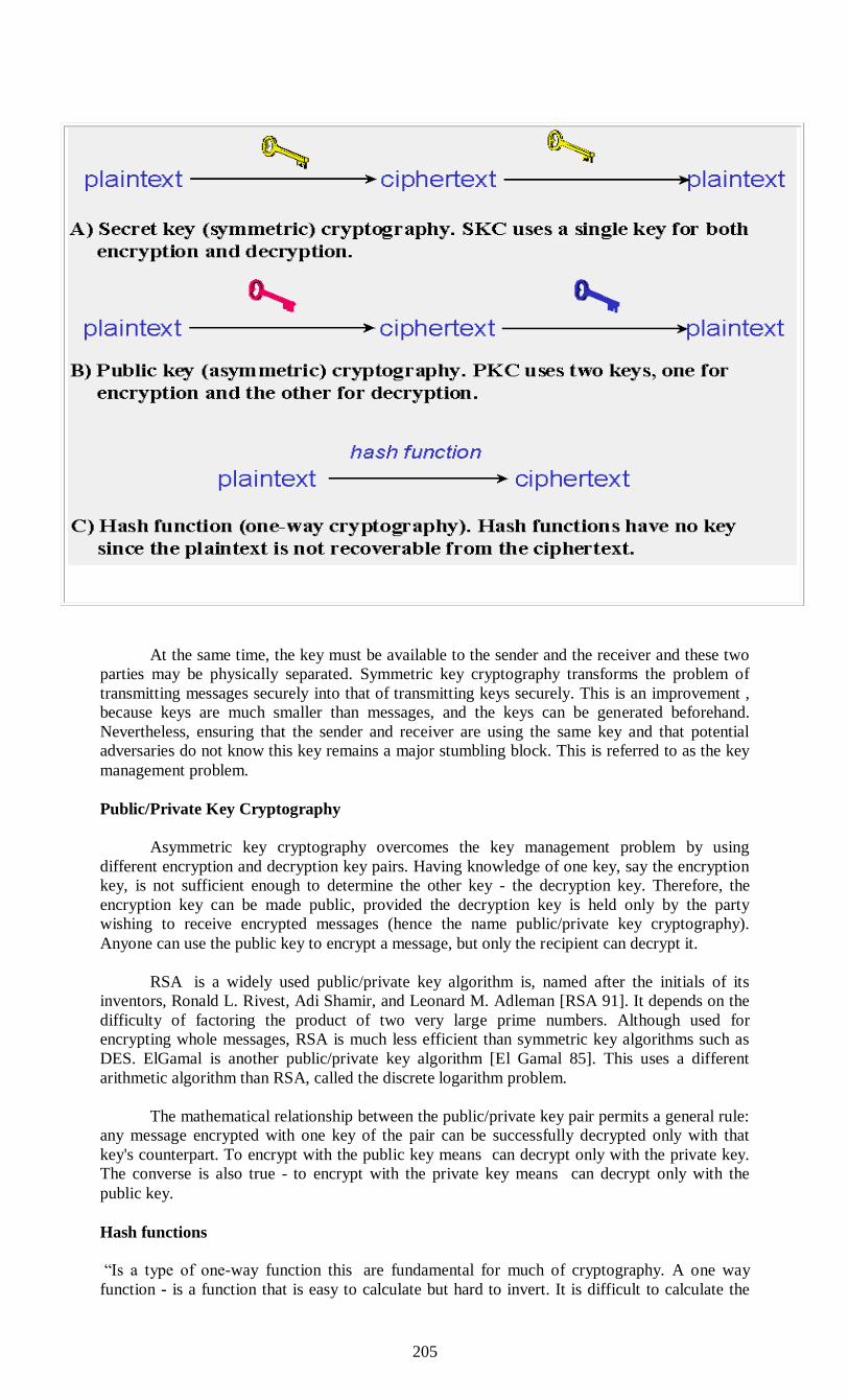
205
At the same time, the key must be available to the sender and the receiver and these two
parties may be physically separated. Symmetric key cryptography transforms the problem of
transmitting messages securely into that of transmitting keys securely. This is an improvement ,
because keys are much smaller than messages, and the keys can be generated beforehand.
Nevertheless, ensuring that the sender and receiver are using the same key and that potential
adversaries do not know this key remains a major stumbling block. This is referred to as the key
management problem.
Public/Private Key Cryptography
Asymmetric key cryptography overcomes the key management problem by using
different encryption and decryption key pairs. Having knowledge of one key, say the encryption
key, is not sufficient enough to determine the other key - the decryption key. Therefore, the
encryption key can be made public, provided the decryption key is held only by the party
wishing to receive encrypted messages (hence the name public/private key cryptography).
Anyone can use the public key to encrypt a message, but only the recipient can decrypt it.
RSA is a widely used public/private key algorithm is, named after the initials of its
inventors, Ronald L. Rivest, Adi Shamir, and Leonard M. Adleman [RSA 91]. It depends on the
difficulty of factoring the product of two very large prime numbers. Although used for
encrypting whole messages, RSA is much less efficient than symmetric key algorithms such as
DES. ElGamal is another public/private key algorithm [El Gamal 85]. This uses a different
arithmetic algorithm than RSA, called the discrete logarithm problem.
The mathematical relationship between the public/private key pair permits a general rule:
any message encrypted with one key of the pair can be successfully decrypted only with that
key's counterpart. To encrypt with the public key means can decrypt only with the private key.
The converse is also true - to encrypt with the private key means can decrypt only with the
public key.
Hash functions
“Is a type of one-way function this are fundamental for much of cryptography. A one way
function - is a function that is easy to calculate but hard to invert. It is difficult to calculate the
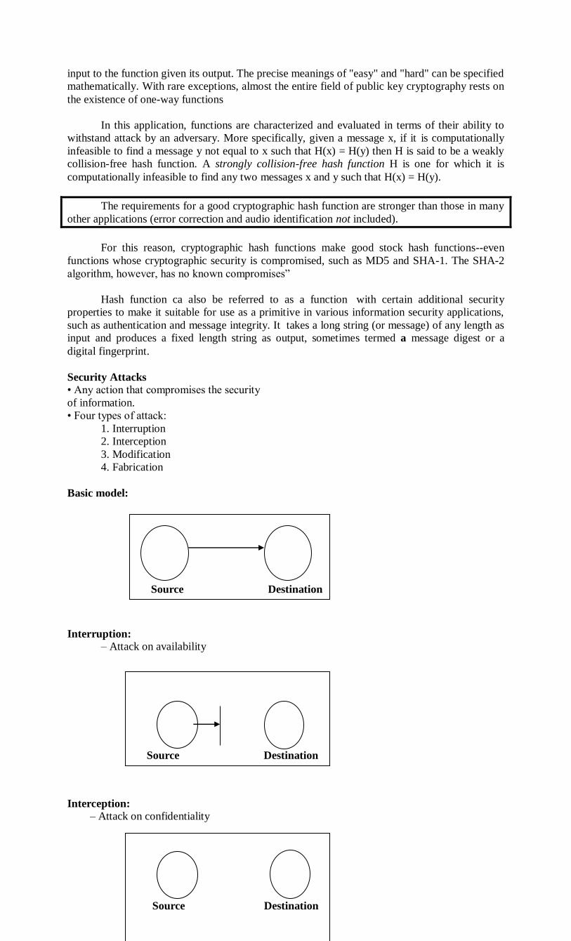
206
input to the function given its output. The precise meanings of "easy" and "hard" can be specified
mathematically. With rare exceptions, almost the entire field of public key cryptography rests on
the existence of one-way functions
In this application, functions are characterized and evaluated in terms of their ability to
withstand attack by an adversary. More specifically, given a message x, if it is computationally
infeasible to find a message y not equal to x such that H(x) = H(y) then H is said to be a weakly
collision-free hash function. A strongly collision-free hash function H is one for which it is
computationally infeasible to find any two messages x and y such that H(x) = H(y).
The requirements for a good cryptographic hash function are stronger than those in many
other applications (error correction and audio identification not included).
For this reason, cryptographic hash functions make good stock hash functions--even
functions whose cryptographic security is compromised, such as MD5 and SHA-1. The SHA-2
algorithm, however, has no known compromises”
Hash function ca also be referred to as a function with certain additional security
properties to make it suitable for use as a primitive in various information security applications,
such as authentication and message integrity. It takes a long string (or message) of any length as
input and produces a fixed length string as output, sometimes termed a message digest or a
digital fingerprint.
Security Attacks
• Any action that compromises the security
of information.
• Four types of attack:
1. Interruption
2. Interception
3. Modification
4. Fabrication
Basic model:
Interruption:
– Attack on availability
Interception:
– Attack on confidentiality
Source Destination Source Destination
Source Destination
Source Destination

207
• Modification:
– Attack on integrity
• Fabrication:
– Attack on authenticity
Data Modification
After an attacker has read data, the next logical step is to alter it. An attacker can modify
the data in the packet without the knowledge of the sender or receiver. Even if do not require
confidentiality for all communications, do not want any of messages to be modified in transit.
For example, if are exchanging purchase requisitions, do not want the items, amounts, or billing
information to be modified.
Identity Spoofing (IP Address Spoofing)
Most networks and operating systems use the IP address of a computer to identify a valid
entity. In certain cases, it is possible for an IP address to be falsely assumed— identity spoofing.
An attacker might also use special programs to construct IP packets that appear to originate from
valid addresses inside the corporate intranet.
After gaining access to the network with a valid IP address, the attacker can modify,
reroute, or delete data. The attacker can also conduct other types of attacks, as described in the
following sections.
I
S
D
I
S
D
I

208
Password-Based Attacks
A common denominator of most operating system and network security plans is
password-based access control. This means access rights to a computer and network resources
are determined by user name and password.
Older applications do not always protect identity information as it is passed through the
network for validation. This might allow an eavesdropper to gain access to the network by
posing as a valid user.
When an attacker finds a valid user account, the attacker has the same rights as the real
user. Therefore, if the user has administrator-level rights, the attacker also can create accounts
for subsequent access at a later time.
After gaining access to the network with a valid account, an attacker can do any of the
following:
Obtain lists of valid user and computer names and network information.
Modify server and network configurations, including access controls and routing tables.
Modify, reroute, or delete the data.
Denial-of-Service Attack
Unlike a password-based attack, the denial-of-service attack prevents normal use of computer or
network by valid users.
After gaining access to the network, the attacker can do any of the following:
Randomize the attention of Internal Information Systems staff so that they do not see the
intrusion immediately, which allows the attacker to make more attacks during the
diversion.
Send invalid data to applications or network services, which causes abnormal termination
or behavior of the applications or services.
Flood a computer or the entire network with traffic until a shutdown occurs because of
the overload.
Block traffic, which results in a loss of access to network resources by authorized users.
Man-in-the-Middle Attack
As the name indicates, a man-in-the-middle attack occurs when someone between the
persons with whom are communicating is actively monitoring, capturing, and controlling
communication transparently. For example, the attacker can re-route a data exchange. When
computers are communicating at low levels of the network layer, the computers might not be
able to determine with whom they are exchanging data.
Man-in-the-middle attacks are like someone assuming identity in order to read message.
The person on the other end might believe it is because the attacker might be actively replying to
keep the exchange going and gain more information. This attack is capable of the same damage
as an application-layer attack, described later in this section.
Compromised-Key Attack
A key is a secret code or number necessary to interpret secured information. Although
obtaining a key is a difficult and resource-intensive process for an attacker, it is possible. After
an attacker obtains a key, that key is referred to as a compromised key.
An attacker uses the compromised key to gain access to a secured communication
without the sender or receiver being aware of the attack.With the compromised key, the attacker
can decrypt or modify data, and try to use the compromised key to compute additional keys,
which might allow the attacker access to other secured communication.
209
Sniffer Attack
A sniffer is an application or device that can read, monitor, and capture network data exchanges
and read network packets. If the packets are not encrypted, a sniffer provides a full view of the
data inside the packet. Even encapsulated (tunneled) packets can be broken open and read unless
they are encrypted and the attacker does not have access to the key.
Using a sniffer, an attacker can do any of the following:
Analyze network and gain information to eventually cause network to crash or to
become corrupted.
Read communications.
Application-Layer Attack
An application-layer attack targets application servers by deliberately causing a fault in a
server's operating system or applications. This results in the attacker gaining the ability to bypass
normal access controls. The attacker takes advantage of this situation, gaining control of
application, system, or network, and can do any of the following:
Read, add, delete, or modify data or operating system.
Introduce a virus program that uses computers and software applications to copy viruses
throughout network.
Introduce a sniffer program to analyze network and gain information that can eventually
be used to crash or to corrupt systems and network.
Abnormally terminate data applications or operating systems.
Disable other security controls to enable future attacks.

210
QUESTIONS
Section A:
1. Define DNS.
2. What is zones
3. What is the uses of E-mail?
4. In e-mail, ASCII symbols are called _________&_________.
5. What is Reporting?
6. Expand MIME.
7. What is DES?
8. RSA refers to _________,_________&________.
9. A fixed length of bit string called__________.
10. What is Message transfer ?
Section B:
1. Define Domain Name space with example.
2. Define Domain Name System.
3. What are uses of E-mail?
4. Explain the five basic principles of e-mail.
5. Define Cryptography.
6. Write a short note on Substitution ciphers.
7. What is Public-key algorithm?
8. Define other Public-key algorithm.
9. Write about Digital Signatures.
10.Write sort notes on cryptography
Section C:
1. Describe about Name servers with example.
2. Discuss about Domain Name Space & Domain Name System.
3. Discuss about email
4. Explain a) Architecture and services b) User Agent.
5. Explain Encryption model in Cryptography with example.
6. Describe about One-time pads with example.
7. Discuss about DES and Triple DES with example.
8. Describe the two Fundamental Principles of Cryptography.
9. Discuss about AES algorithm with example.
10. Explain in detail about RSA algorithm.

211
Related Documents