www.nordictrack.com Model No. NTEL07808.0 Serial No. Write the serial number in the space above for reference. @_-%( (oSeur iadeNrU_d beerf Deamle) QUESTIONS? As a manufacturer, we are commit- ted to providing complete customer satisfaction. If you have questions, or if parts are damaged or missing, DO NOT CONTACT THE STORE; please contact Customer Care. IMPORTANT: You must note the product model number and serial number (see the drawing above) before contacting us: CALL TOLL-FREE: 1-888-825-2588 Mon.-Fri. 6 a.m.-6 p.m. MT Sat. 8 a.m.-4 p.m. MT ON THE WEB: www.nordictrackservice.com "=='=1_ .... E7 Ff_rlt E_fiv_ USER'S MANUAL

Welcome message from author
This document is posted to help you gain knowledge. Please leave a comment to let me know what you think about it! Share it to your friends and learn new things together.
Transcript

www.nordictrack.com
Model No. NTEL07808.0Serial No.
Write the serial number in thespace above for reference.
@_-%( (oSeuriadeNrU_dbeerfDeamle)
QUESTIONS?As a manufacturer, we are commit-ted to providing complete customersatisfaction. If you have questions,or if parts are damaged or missing,DO NOT CONTACT THE STORE;please contact Customer Care.
IMPORTANT: You must note theproduct model number and serialnumber (see the drawing above)before contacting us:
CALL TOLL-FREE:
1-888-825-2588Mon.-Fri. 6 a.m.-6 p.m. MTSat. 8 a.m.-4 p.m. MT
ON THE WEB:www.nordictrackservice.com
"=='=1_ ....
E7Ff_rlt E_fiv_
USER'S MANUAL

TABLE OF CONTENTS
WARNING DECAL PLACEMENT .............................................................. 2IMPORTANT PRECAUTIONS ................................................................ 3BEFORE YOU BEGIN ...................................................................... 4ASSEMBLY ............................................................................... 5HOW TO USE THE ELLIPTICAL EXERCISER .................................................. 12MAINTENANCE AND TROUBLESHOOTING ................................................... 21EXERCISE GUIDELINES ................................................................... 22PART LIST .............................................................................. 23EXPLODED DRAWING .................................................................... 25ORDERING REPLACEMENT PARTS .................................................. Back CoverLIMITED WARRANTY .............................................................. Back Cover
WARNING DECAL PLACEMENT
This drawing shows the location(s) ofthe warning decal(s). If a decal ismissing or illegible, see the frontcover of this manual and request afree replacement decal. Apply thedecal in the location shown. Note:
The decal(s) may not be shown atactual size.
• Misuse ofthis machinemay result in seriousinjury.
• Read user's manualpriorto use and followall warnings andinstructions.
• Do not allow childrenonor around machine.
• Pedals continue tospin when you stoppedaling,
• Spinning pedals cancause injury.
• Reduce pedal speedin a controlled manner.
User weight must notexceed 275 pounds.
• Replace label ifdamaged, illegible, or
removed, [_
NordicTrack is a registered trademark of ICON IP, Inc.
2

IMPORTANT PRECAUTIONS
3
BEFORE YOU BEGIN
Thank you for selecting the new NordicTrack ® E7 SVFRONT DRIVE elliptical exerciser. The E7 SV FRONTDRIVE elliptical exerciser provides a wide array of fea-tures designed to make your workouts at home moreeffective and enjoyable.
For your benefit, read this manual carefully beforeyou use the elliptical exerciser. If you have ques-tions after reading this manual, please see the front
cover of this manual. To help us assist you, note theproduct model number and serial number before con-tacting us. The model number and the location of theserial number decal are shown on the front cover ofthis manual.
Before reading further, please familiarize yourself withthe parts that are labeled in the drawing below.
Console Handgrip Pulse Sensor
Handlebar
Water Bottle Holder*
Ramp Handle
PedalWheel
Ramp
Handle
Roller
*Water bottle is not included
4

ASSEMBLY
Assembly requires two persons. Place all parts of the elliptical exerciser in a cleared area and remove thepacking materials. Do not dispose of the packing materials until assembly is completed.
In addition to the included tool(s), assembly requires a Phillips screwdriver _====_, two adjustable
wrenches _, and a rubber mallet _.
As you assemble the elliptical exerciser, use the drawings below to identify small parts. The number in parenthe-ses below each drawing is the key number of the part, from the PART LIST near the end of this manual. Thenumber following the parentheses is the quantity needed for assembly. Note: Some small parts may havebeen preassembled. If a part is not in the hardware kit, check to see if it has been preassembled.
16mm WaveM8 SplitWasher (83)-9 Washer (54)-2
M8 Locknut(1O2)-8
M10 Locknut(92)-2
19mm WaveWasher (66)-4
M4 x 16mmScrew (104)-10
M8 x 80mm PatchScrew (84)-2
HM10 Washer
(95)-2
1M8 x 25mm
Washer (98)-6
M8 x 19mm PatchScrew (82)-15
M8 x 38mmBolt (96)-8
MIO x 45mm PatchScrew (99)-4
M10 x 60mmBolt (100)-2
5

.
Attach the Front Stabilizer (6) to the Frame (1)with two M8 x 80mm Patch Screws (84).
84
. Orient the Ramp (3) as shown. Then, insert theRamp into the Frame (1).
Attach the Ramp (3) with five M8 x 19mm PatchScrews (82) and five M8 Split Washers (83).
82
82
. While a second person holds the Upright (4)near the Frame (1), connect the Upper WireHarness (110) to the Lower Wire Harness (111).
Tip: Avoid pinching the wires. Slide theUpright (4) onto the Frame (1). Attach theUpright with four M8 x 19mm Patch Screws (82)and four M8 Split Washers (83). Do not tightenthe Patch Screws yet.
Avoid pinchingthe wires
83
6

Apply a small amount of the included grease tothe right Crank Arm (20) and to a 19mm WaveWasher (66).
Slide a Crank Arm Spacer (55) and the 19mmWave Washer (66) onto the right Crank Arm(20).
Identify the Right Roller Arm (59), which ismarked with a "Right" sticker, and orient it asshown.
Slide the Right Roller Arm (59) onto the rightCrank Arm (20). Attach the Right Roller Armwith an M8 x 19mm Patch Screw (82), an AxleCover (53), and an M8 x 25mm Washer (98); toavoid breaking the Axle Cover, do not over-tighten the Patch Screw.
Repeat this step for the Left Roller Arm (notshown).
Grease
98
59
53
. Identify the Right Pedal Bracket (64), which ismarked with a "Right" sticker.
Apply a small amount of grease to the inside ofthe tube on the Right Roller Arm (59) and to thebarrel of an M10 x 60mm Bolt (100).
Attach the Right Pedal Bracket (64) to the RightRoller Arm (59) with the M10 x 60mm Bolt(100), an M10 Washer (95), and an M10Locknut (92). Do not overtighten the Locknut;the Right Pedal Bracket must pivot freely.
Repeat this step for the Left Pedal Bracket(48).
48
92
\
100
Grease
59
7

6. 6Identify the Right Handlebar (61) and the RightHandlebar Leg (60), which are marked with"Right" stickers, and orient them as shown.Make sure that the hexagonal holes are inthe indicated location.
Slide the Right Handlebar (61) onto the RightHandlebar Leg (60).
Attach the Right Handlebar (61) with two M8 x38mm Bolts (96) and two M8 Locknuts (102).Make sure that the Locknuts are in the
hexagonal holes.
Repeat this step for the Left Handlebar (notshown) and the Left Handlebar Leg (notshown).
61
96
102
HexagonalHoles
60
. Apply a small amount of grease to the PivotAxle (35) and to a 16mm Wave Washer (54).
Insert the Pivot Axle (35) through the Upright (4)and then center it.
Slide the 16mm Wave Washer (54), an InnerHandlebar Cover (68), and the Right HandlebarLeg (60) onto the right side of the Pivot Axle(35).
Repeat this step for the Left Handlebar Leg(not shown).
Tighten an M8 x 19mm Patch Screw (82) andan M8 x 25mm Washer (98) into each end ofthe Pivot Axle (35).
7
Grease
68
60
98
8

8. 8Attach an Outer Handlebar Cover (67) and theInner Handlebar Cover (68) around the RightHandlebar Leg (60) with two M4 x 16mmScrews (104).
Repeat this step for the other side of theelliptical exerciser.
68
60
67
. Apply a small amount of grease to the axle onthe Right Handlebar Leg (60) and to a 19mmWave Washer (66).
Identify the Right Pedal Arm (58), which ismarked with a "Right" sticker, and orient it asshown.
Slide the 19mm Wave Washer (66) and theRight Pedal Arm (58) onto the Right HandlebarLeg (60).
Attach the Right Pedal Arm (58) with an M8 x19mm Patch Screw (82), an Axle Cover (53),and an M8 x 25mm Washer (98); to avoidbreaking the Axle Cover, do not overtightenthe Patch Screw.
Repeat this step for the Left Pedal Arm (notshown).
Grease
58
8 53
82
9

10. Attach the Right Pedal Arm (58) to the RightPedal Bracket (64) with two M10 x 45mm PatchScrews (99).
Repeat this step for the Left Pedal Arm (44).
10
44
58
11. Identify the Right Pulse Bar (9), which ismarked with a "Right" sticker.
See the inset drawing. Locate the wire tie inthe Upright (4). Tie the lower end of the wire tieto the Pulse Wire (63) in the Right Pulse Bar(9). Next, pull the upper end of the wire tieupward out of the top of the Upright. Then, untieand discard the wire tie.
Slide the Right Pulse Bar (9) onto the right sideof the Upright (4). Make sure that the hexago-nal holes are in the indicated location.
Tip: Avoid pinching the wires. Attach theRight Pulse Bar (9) with two M8 x 38mm Bolts(96) and two M8 Locknuts (102). Make surethat the Locknuts are in the hexagonalholes.
Repeat this step for the Left Pulse Bar (8).
11
Wire Tie
Ill"63
110
HexagonalHoles
Avoid pinchingthe wires
Tie
10
96

12.AttachtheWaterBottleHolder(37)to theUpright(4)withtwoM4x 16mmScrews(104).
12
13.WhileasecondpersonholdstheConsole(7)neartheUpright(4),connecttheconsolewiretotheUpperWireHarness(110).Then,connecttheconsolepulsewirestothePulseWires(63).
Insert the excess wire downward into theUpright (4).
Tip: Avoid pinching the wires. Attach theConsole (7) to the Upright (4) with four M4 x16mm Screws (104).
See step 3. Tighten the M8 x 19mm PatchScrews (82).
13Avoid pinching
the wires
Console Wire
110
104
14. Plug the power adapter into the jack on the back of the console (see HOW TO PLUG IN THE POWERADAPTER on page 12). IMPORTANT: If the elliptical exerciser has been exposed to cold temperatures,allow it to warm to room temperature before plugging in the power adapter. If you do not do this, youmay damage the console displays or other electronic components.
Make sure that all parts are properly tightened before you use the elliptical exerciser. Note: After assem-bly is completed, some extra parts may be left over. Place a mat beneath the elliptical exerciser to protect thefloor.
11
HOW TO USE THE ELLIPTICAL EXERCISER
HOW TO PLUG IN THE POWER ADAPTER
Plug one end of the included power adapter into thejack on the console. Plug the other end of the poweradapter into an appropriate outlet that is properlyinstalled in accordance with all local codes and ordi-nances.
Note: The console can also be operated with four 1.5VD batteries (not included); alkaline batteries are rec-ommended. Locate the battery cover on the back ofthe console. Remove the battery cover, insert the bat-teries into the battery compartment, and then reattachthe battery cover. Make sure to orient the batteriesas shown by the diagrams inside the battery com-partment.
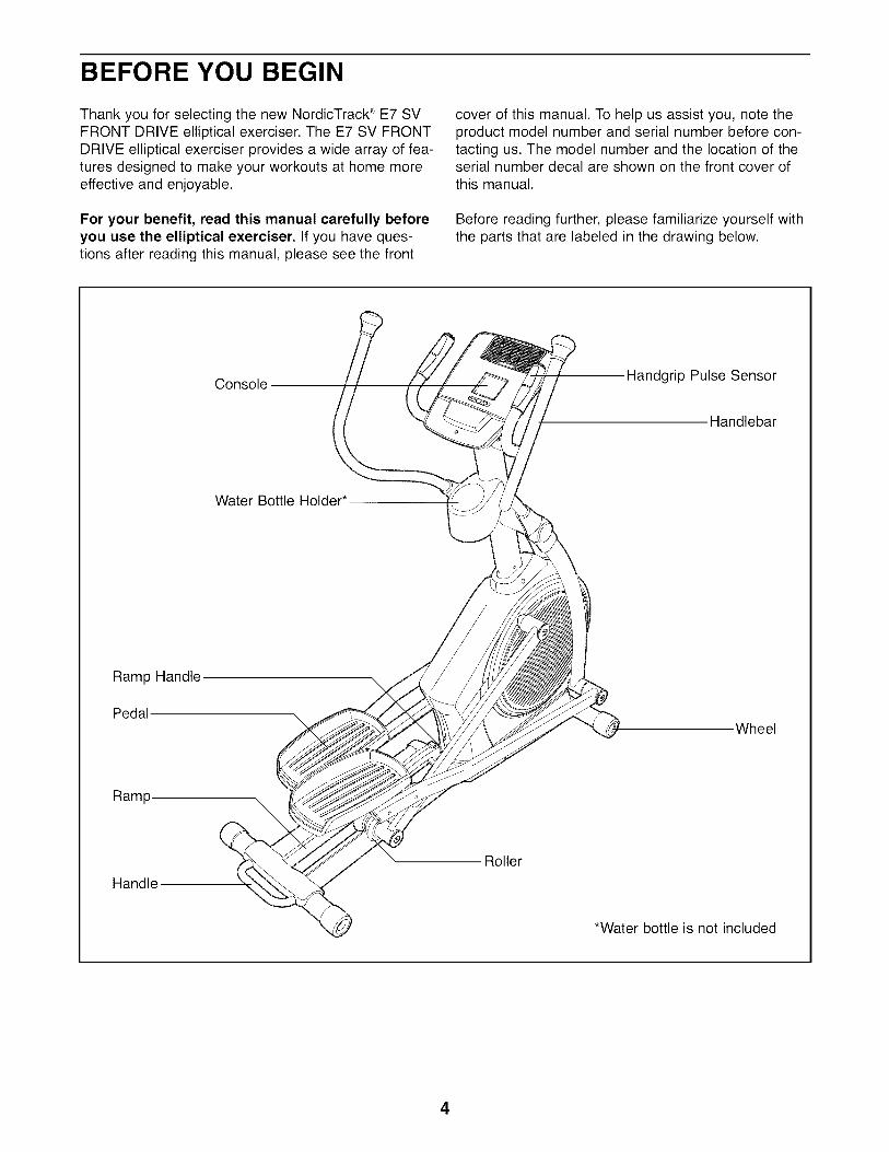
HOW TO MOVE THE ELLIPTICAL EXERCISER
Due to the size and weight of the ellipticalexerciser, moving it requires two persons. Stand infront of the elliptical exerciser, hold the upright, andplace one foot against one of the front wheels. Pull onthe upright and have a second person lift the handleon the ramp until the elliptical exerciser will roll on thefront wheels. Carefully move the elliptical exerciser tothe desired location, and then lower it to the floor.
Pull onupright
Placeyour foot
here
Lift h_ 7
12

HOW TO EXERCISE ON THE ELLIPTICALEXERCISER
To mount the elliptical exerciser, hold the handlebarsand step onto the pedal that is in the lower position.Then, step onto the other pedal. Push the pedals untilthey begin to move with a continuous motion. Note:The crank arms can turn in either direction. It is
recommended that you turn the crank arms in thedirection shown by the arrow; however, for variety,you can turn the crank arms in the opposite direc-tion.
HOW TO CHANGE THE INCLINE OF THE RAMP
To vary the motion of the pedals, you can change theincline of the ramp. To change the incline, press thelatch button, pull the ramp handle, and raise or lowerthe ramp to the desired incline level. Then, release thelatch button and engage the latch pin into one of theadjustment holes in the frame. The white line on thelatch button must be visible or the latch pin is not fullyengaged. Make sure that the latch pin is firmlyengaged in one of the adjustment holes in theframe.
LatchRamp Button
Handle\
CrankArm
Ramp
To dismount the elliptical exerciser, wait until the ped-als come to a complete stop. Note: The ellipticalexerciser does not have a free wheel; the pedalswill continue to move until the flywheel stops.When the pedals are stationary, step off the higherpedal first. Then, step off the lower pedal.
13

CONSOLE DIAGRAM
ENDURANCE
PERFORMANCE
?fitTRAINER
/ WORKOUTS\
\
\\\\\
RESEF
B l"!,e'!U'U B
TIME
2.64 ,5uDISTANCE SPEED
WORKOUTS a[ iFIT.COM
ODOMETER
WEIGHT LOSS 2
WEIGHT LOSS 3
WEIGIII LOSS 4
/
d fitWEIGHT LOSS
WORKOUTS
SILENT MAGNETIC RESISTANCE /
/V A
/J
FEATURES OF THE CONSOLE
The revolutionary console offers an array of featuresdesigned to make your workouts more effective andenjoyable. When you use the manual mode of theconsole, you can change the resistance of the pedalswith the touch of a button. While you exercise, theconsole will display continuous exercise feedback. Youcan also measure your heart rate using the handgrippulse sensor.
In addition, the console offers twelve trainer workoutsand four weight loss workouts. Each workout automat-ically changes the resistance of the pedals as it guidesyou through an effective workout.
The console features the iFit Interactive WorkoutSystem, which enables the console to accept iFitcards containing workouts designed to help youachieve specific fitness goals. For example, loseunwanted pounds with the 8-week Weight Loss work-
out. iFit workouts control the resistance of the pedalswhile the voice of a personal trainer coaches youthrough your workouts, iFit cards are available sepa-rately. To purchase iFit cards, go to www.iFit.comor call the telephone number on the front cover ofthis manual, iFit cards are also available at selectstores.
You can even connect your MP3 player or CD playerto the console's sound system and listen to yourfavorite music or audio books while you exercise.
To use the manual mode, see page 15. To use atrainer workout, see page 17. To use a weight lossworkout, see page 18. To use an iFit workout, seepage 19. To use the sound system, see page 19. Tochange console settings, see page 20.
Note: If there is a sheet of clear plastic on the faceof the console, remove the plastic.
14

HOW TO USE THE MANUAL MODE
1. Begin pedaling or press any button on theconsole to turn on the console.
A moment after you begin pedaling or press a but-ton, a tone will sound, and the display will light.
2. Select the manual mode.
Each time you turnon the console, themanual mode will
be selected. If youhave selected aworkout, reselectthe manual mode
by pressing any ofthe Workouts but-
tons repeatedly
F'I F'I,F'I t"llUU'UU
TiME
f"H-IFI Fll-1U,U LJ U.U
DISTANCE SPEED
until zeros appear in the display.
3. Change the resistance of the pedals asdesired.
AsyoupedaI schange the resis-tance of the pedalsby pressing theSilent MagneticResistance
increase and decrease buttons. Note: After youpress the buttons, it will take a moment for thepedals to reach the selected resistance level.
4. Follow your progress with the display.
The lower left dis-
I I.exercise, the lower 22D B _Sleft display can D,STANDECA_O_,ESshow the elapsed __time and the dis-
tance (in miles or kilometers) that you havepedaled. Note: When a workout is selected, thedisplay will show the time remaining in the workoutinstead of the elapsed time.
The lower right jdisplay--The lower Jright display canshow the your ped-aling speed (in roB'miles or kilometers
per hour) and the approximate number of caloriesthat you have burned. The display also showsyour heart rate when you use the handgrip pulsesensor (see step 5 on page 16).
theupperI ¸display--The upper
display can show t_ _'==._
the elapsed time, t _m_,_Jthe distance that _ -,you have pedaled,your pedaling speed, and the approximate numberof calories you have burned. Press the PriorityDisplay button repeatedly until the upper displayshows the information that you are most interestedin viewing. Note: While information is shown in theupper display, the same information will not beshown in the lower left or lower right display.
The lower I
display--The lowerdisplay will show atrack representing1/4 mile (402meters). As you
220 124DISTANCE SPEED
exercise, indicators will appear in successionaround the track until the entire track appears. Thetrack will then disappear and the indicators willagain begin to appear in succession
To view the trip dis-tance, press theOdometer buttononce. To reset the
trip distance to zero,press the Reset but-ton.
225B IDISTANCE
krl P
To view the total distance pedaled since the ellipti-cal exerciser was purchased, press the Odometerbutton a second time. To exit the odometer infor-
mation, press the Odometer button a third time.
Note: The console can show pedaling speed anddistance in either miles or kilometers. To view or
change the unit of measurement, see HOW TOCHANGE CONSOLE SETTINGS on page 20.
15

5. Measure your heart rate if desired.
If there are sheets I
of clear plastic on I Contactsthe metal con-tacts on thehandgrip pulsesensor, removethe plastic. Tomeasure yourheart rate, hold thehandgrip pulsesensor with yourpalms restingagainst the metal contacts. Avoid moving yourhands or gripping the contacts tightly.
When your pulse is !1detected, a flashingheart symbol willappear in the dis-play, and then yourheart rate willappear. For the most accurate heart rate reading,hold the contacts for at least 15 seconds. Note: Ifyou continue to hold the handgrip pulse sensor,the display will show your heart rate for up to 30seconds.
If the display does not show your heart rate, makesure that your hands are positioned as described.Be careful not to move your hands excessively orto squeeze the metal contacts tightly. For optimalperformance, clean the metal contacts using a softcloth; never use alcohol, abrasives, or chemi-cals to clean the contacts.
6. When you are finished exercising, the consolewill turn off automatically.
If the pedals do not move for several seconds, atone will sound and the console will pause.
If the pedals do not move for several minutes andthe buttons are not pressed, the console will turnoff and the display will be reset.
16

HOW TO USE A TRAINER WORKOUT
1. Begin pedaling or press any button on theconsole to turn on the console.
A moment after you begin pedaling or press a but-ton, a tone will sound, and the display will light.
2. Select a trainer workout.
To select a trainer
workout, press theWarm Up, Aerobic,Endurance, orPerformance button
repeatedly until thename of thedesired workout
appears in the dis-play. The workouttime and a profile of
u'uu u.u_ME SPEED
IProfile
the resistance levels for the workout will also
appear in the display.
3. Begin pedaling to start the workout.
Each workout is divided into 20, 30 or 45 one-minute segments. One resistance level isprogrammed for each segment. Note: The sameresistance level may be programmed for consecu-tive segments.
The resistance level for the first segment willappear in the display for a few seconds. Duringthe workout, the workout profile will show yourprogress (see the drawing above). The flashingsegment of the profile represents the current seg-
ment of the workout. The height of the flashingsegment indicates the resistance level for the cur-rent segment. At the end of each segment of theworkout, a series of tones will sound and the nextsegment of the profile will begin to flash. If a differ-ent resistance level is programmed for the nextsegment, the resistance level will appear in thedisplay for a few seconds to alert you. The resis-tance of the pedals will then change.
If the resistance level for the current segment istoo high or too low, you can manually override thesetting by pressing the Silent Magnetic Resistancebuttons. IMPORTANT: When the current seg-ment of the workout ends, the pedals willautomatically adjust to the resistance levelprogrammed for the next segment.
The workout will continue in this way until the lastsegment ends. To stop the workout at any time,stop pedaling. A tone will sound and the time willstop counting. To restart the workout, simplyresume pedaling.
4. Follow your progress with the display.
See step 4 on page 15.
5. Measure your heart rate if desired.
.
See step 5 on page 16.
When you are finished exercising, the consolewill turn off automatically.
See step 6 on page 16.
17

HOW TO USE A WEIGHT LOSS WORKOUT
1. Begin pedaling or press any button on theconsole to turn on the console.
A moment after you begin pedaling or press a but-ton, a tone will sound, and the display will light.
2. Select a weight loss workout.
To select a weightloss workout, pressthe desired WeightLoss button. Theworkout time and aprofile of the resis-tance levels for theworkout will alsoappear in the dis-play.
_,t"_t'I t'_t'lU'UU U,U
TIME SPEED
Profile
3. Begin pedaling to start the workout.
Each workout is divided into 30 one-minute seg-ments. One resistance level is programmed foreach segment. Note: The same resistance levelmay be programmed for consecutive segments.
The resistance level for the first segment willappear in the display for a few seconds. Duringthe workout, the workout profile will show yourprogress (see the drawing above). The flashingsegment of the profile represents the current seg-ment of the workout. The height of the flashingsegment indicates the resistance level for the cur-
rent segment. At the end of each segment of theworkout, a series of tones will sound and the nextsegment of the profile will begin to flash. If a differ-ent resistance level is programmed for the nextsegment, the resistance level will appear in thedisplay for a few seconds to alert you. The resis-tance of the pedals will then change.
If the resistance level for the current segment istoo high or too low, you can manually override thesetting by pressing the Silent Magnetic Resistancebuttons. IMPORTANT: When the current seg-ment of the workout ends, the pedals willautomatically adjust to the resistance levelprogrammed for the next segment.
The workout will continue in this way until the lastsegment ends. To stop the workout at any time,stop pedaling. A tone will sound and the time willstop counting. To restart the workout, simplyresume pedaling.
4. Follow your progress with the display.
See step 4 on page 15.
5. Measure your heart rate if desired.
.
See step 5 on page 16.
When you are finished exercising, the consolewill turn off automatically.
See step 6 on page 16.
18

HOW TO USE AN IFIT WORKOUT HOW TO USE THE SOUND SYSTEM
1. Begin pedaling or press any button on theconsole to turn on the console.
A moment after you begin pedaling or press a but-ton, a tone will sound, and the display will light.
2. Insert an iFit card and select a workout.
To use an iFit workout, insert an iFit card into theiFit slot; make sure that the iFit card is oriented sothe metal contacts are face down and are facingthe slot. When the iFit card is properly inserted,the indicator next to the slot will light and wordswill appear in the display.
To play music or audio books through the console'ssound system while you exercise, plug an audio cable(not included) into the jack on the console and into ajack on your MP3 player or CD player; make surethat the audio cable is fully plugged in.
Next, press the play button on your MP3 player or CDplayer. Adjust the volume level using the volume con-trol on your MP3 player or CD player.
iFit Slot___ iFit Card
.
Next, select the desired workout on the iFit cardby pressing the increase and decrease buttonsnext to the iFit slot.
A moment after you select a workout, the voice ofa personal trainer will begin guiding you throughyour workout, iFit workouts function in the sameway as trainer workouts. To use the workout, seesteps 3 to 6 on page 17.
When you are finished exercising, remove theiFit card.
Remove the iFit card when you are finished exer-cising. Store the iFit card in a secure place.
19

HOW TO CHANGE CONSOLE SETTINGS 3. Select a unit of measurement if desired.
The console features a user mode that allows you toselect a unit of measurement and a backlight optionfor the console and to view console usage information.
1. Select the user mode.
To select the user mode, press and hold down thePriority Display button for a few seconds until theuser mode information appears in the display.
2 Select a backlight option if desired.
The console hasthree backlightoptions. The ONoption keeps thebacklight on whilethe console is on.The AUTO optionkeeps the backlighton only while youare pedaling. TheOFF option turns the backlight off.
B ETIME
The upper display will show the currently selectedbacklight option. Press the Silent MagneticResistance increase button repeatedly to selectthe desired backlight option.
The console can show pedaling speed and dis-tance in either miles or kilometers.
The lower right display will show the selected unitof measurement. An E for English miles or an Mfor metric kilometers will appear in the lower rightdisplay. To change the unit of measurement, pressthe Silent Magnetic Resistance decrease buttonrepeatedly.
Note: When you replace the batteries, it may benecessary to reselect the unit of measurement.
4. View console usage information if desired.
The lower left display will show the total number ofhours that the console has been used since theelliptical exerciser was purchased.
5. Exit the user mode.
Press the Priority Display button to save the con-sole settings and exit the user mode.
20

MAINTENANCE AND TROUBLESHOOTING
Inspect and tighten all parts of the elliptical exerciserregularly. Replace any worn parts immediately.
To clean the elliptical exerciser, use a damp cloth anda small amount of mild soap. IMPORTANT: To avoiddamage to the console, keep liquids away fromthe console and keep the console out of directsunlight.
CONSOLE TROUBLESHOOTING
If the console does not display your heart rate whenyou hold the handgrip pulse sensor, or if the displayedheart rate appears to be too high or too low, see step5 on page 16.
HOW TO ADJUST THE DRIVE BELT
If the pedals slip whileyou are pedaling, evenwhile the resistance isadjusted to the highestlevel, the drive belt mayneed to be adjusted. Toadjust the drive belt, firstuse a flat screwdriver topry the right Disc (71)carefully away from theright Disc Mount (72). Then, remove the right Disc.
Locate and loosen the M10 x 22mm Bolt (89). Next,tighten the M8 x 38mm Hex Screw (88) until the DriveBelt (113) is tight. Then, retighten the M10 x 22mmBolt.
89
HOW TO ADJUST THE REED SWITCH
If the console does not display correct feedback, thereed switch should be adjusted. To adjust the reedswitch, first use a flat screwdriver to pry the left disccarefully away from the left disc mount. Then, removethe left disc.
Locate the Reed Switch (38). Loosen, but do notremove, the indicated M4 x 16mm Reed Switch Screw(69). Slide the Reed Switch slightly closer to or awayfrom a Magnet (43) on the Pulley (19). Then, retightenthe M4 x 16mm Screw. Turn the Pulley for a moment.Repeat until the console displays correct feedback.
Reattach the left disc by pressing it firmly into the leftdisc mount.
HOW TO GREASE THE ROLLERS
See the EXPLODED DRAWING near the end of this
manual. If the Rollers (51) squeak when moving onthe Ramp (3), apply a small amount of white marinegrease equally to each Roller. Spread the greaseevenly around the Rollers. Pedal the elliptical exercis-er until a thin film of grease is distributed along theRamp; wipe off any excess grease.
Reattach the right disc by pressing it firmly into theright disc mount.
21
EXERCISE GUIDELINES
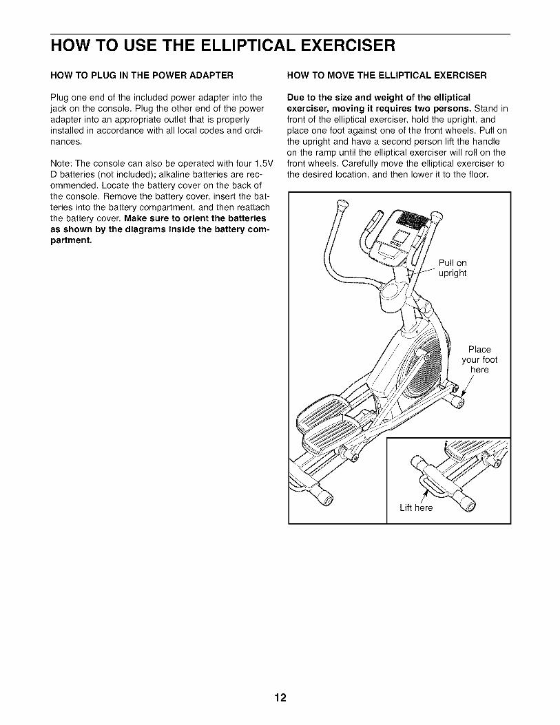
These guidelines will help you to plan your exerciseprogram. For detailed exercise information, obtain areputable book or consult your physician. Remember,proper nutrition and adequate rest are essential forsuccessful results.
EXERCISE INTENSITY
Whether your goal is to burn fat or to strengthen yourcardiovascular system, exercising at the proper inten-sity is the key to achieving results. You can use yourheart rate as a guide to find the proper intensity level.The chart below shows recommended heart rates forfat burning and aerobic exercise.
165 155 145 140 i30 125 115 _
145 138 I30 125 118 110 103 CW_)
125 120 115 I10 105 95 90
20 30 40 50 60 70 80
To find the proper intensity level, find your age at thebottom of the chart (ages are rounded off to the near-est ten years). The three numbers listed above yourage define your "training zone." The lowest number isthe heart rate for fat burning, the middle number is theheart rate for maximum fat burning, and the highestnumber is the heart rate for aerobic exercise.
Burning Fat--To burn fat effectively, you must exer-cise at a low intensity level for a sustained period oftime. During the first few minutes of exercise, yourbody uses carbohydrate calories for energy. Only afterthe first few minutes of exercise does your body beginto use stored fat calories for energy. If your goal is toburn fat, adjust the intensity of your exercise until yourheart rate is near the lowest number in your trainingzone. For maximum fat burning, exercise with yourheart rate near the middle number in your trainingzone.
Aerobic Exercise--If your goal is to strengthen yourcardiovascular system, you must perform aerobicexercise, which is activity that requires large amountsof oxygen for prolonged periods of time. For aerobicexercise, adjust the intensity of your exercise untilyour heart rate is near the highest number in yourtraining zone.
WORKOUT GUIDELINES
Warming Up--Start with 5 to 10 minutes of stretchingand light exercise. A warm-up increases your bodytemperature, heart rate, and circulation in preparationfor exercise.
Training Zone Exercise--Exercise for 20 to 30 min-utes with your heart rate in your training zone. (Duringthe first few weeks of your exercise program, do notkeep your heart rate in your training zone for longerthan 20 minutes.) Breathe regularly and deeply as youexercise-never hold your breath.
Cooling Down--Finish with 5 to 10 minutes ofstretching. Stretching increases the flexibility of yourmuscles and helps to prevent post-exercise problems.
EXERCISE FREQUENCY
To maintain or improve your condition, complete threeworkouts each week, with at least one day of restbetween workouts. After a few months of regular exer-cise, you may complete up to five workouts eachweek, if desired. Remember, the key to success is tomake exercise a regular and enjoyable part of youreveryday life.
22

PART LIST--Model No. NTEL07808.0 Rloo8A
Key No. Qty. Description Key No. Qty.
1 1 Frame 51 22 1 Base 52 2
3 1 Ramp 53 84 1 Upright 54 25 3 M4 x 19mm Screw 55 26 1 Front Stabilizer 56 27 1 Console 57 48 1 Left Pulse Bar 58 1
9 1 Right Pulse Bar 59 110 1 Track Cover 60 111 1 Left Latch Cover 61 1
12 1 Right Latch Cover 62 213 1 Latch Button 63 214 1 Latch Cable 64 1
15 4 Cable Pulley 65 616 1 Latch Spring 66 417 1 Latch Pin 67 218 1 Crank 68 2
19 1 Pulley 69 120 2 Crank Arm 70 2
21 13 M4 x 16mm Flange Screw 71 222 1 Idler 72 2
23 1 C-magnet 73 124 1 Motor Bracket 74 125 1 Resistance Motor 75 126 1 Resistance Rod 76 1027 1 Resistance Disc 77 2
28 1 Flywheel 78 229 1 Flywheel Axle 79 130 6 Stabilizer Bushing 80 131 1 Stabilizer Axle 81 2
32 2 Stabilizer Cap 82 1533 1 Foot 83 934 2 Wheel 84 235 1 Pivot Axle 85 2
36 4 Pivot Bushing 86 237 1 Water Bottle Holder 87 438 1 Reed Switch 88 1
39 2 Clamp 89 140 6 R12 Bearing 90 141 2 Flywheel Bearing 91 242 4 Snap Ring 92 343 2 Magnet 93 444 1 Left Pedal Arm 94 445 1 Left Roller Arm 95 2
46 1 Left Handlebar Leg 96 847 1 Left Handlebar 97 848 1 Left Pedal Bracket 98 849 2 Pedal 99 450 2 Pedal Insert 100 2
Description
Roller
Pedal Arm CapAxle Cover16mm Wave Washer
Crank Arm SpacerPedal Bracket BushingPedal Arm BushingRight Pedal ArmRight Roller ArmRight Handlebar LegRight HandlebarHandlebar CapPulse Sensor Assembly/WireRight Pedal BracketM6 x 25mm Flat Head Screw19mm Wave WasherOuter Handlebar CoverInner Handlebar CoverM4 x 16mm Reed Switch Screw
Inner Pivot BushingDiscDisc MountLeft Shield
Right ShieldShield Cover
V-clipRoller SpacerKeyLong Magnet SpacerShort Magnet SpacerM10 Shoulder ScrewM8 x 19mm Patch Screw
M8 Split WasherM8 x 80mm Patch ScrewM6 x 12mm Hex Patch ScrewM8 x 48mm Hex BoltM8 x 13mm ScrewM8 x 38mm Hex ScrewM10 x 22mm BoltM8 x 80mm Shoulder BoltM10 Fender WasherM10 LocknutM4 x 12mm BoltM4 LocknutM10 WasherM8 x 38mm BoltM8 x 19mm Patch ScrewM8 x 25mm WasherM10 x 45mm Patch ScrewM10 x 60mm Bolt
23

Key No. Qty. Description Key No. Qty. Description
101 2 M8 x 20mm Washer 110 1 Upper Wire Harness102 12 M8 Locknut 111 1 Lower Wire Harness103 1 M3.5 x 12mm Flat Head Screw 112 1 Power Adapter104 17 M4 x 16mm Screw 113 1 Drive Belt105 10 M4 x 10mm Machine Screw 114 2 Foam Grip106 1 M4 x 16mm Bright Screw * - 1" Grommet107 4 Roller Arm Bushing * - Assembly Tool108 12 M6 x 13mm Screw * - Grease Packet109 2 M6 Washer * - User's Manual
Note: Specifications are subject to change without notice. See the back cover of this manual for informationabout ordering replacement parts. *These parts are not illustrated.
24

EXPLODED DRAWING A--Model No. NTEL07808.0 moo8A
81
6978 38
J
20 ""86
82
32
83
1024
30
9129
30
31
34
43
84
34 81
1820
85
86
104 35
109
11
108
15
....-13
36
82
83
.,_ 1716
25

EXPLODED DRAWING B--Model No. NTEL07808.0 RlOO8A
76
99
47
98
44
50"
108
46
53
100
42
77
82
70
45
51
53 c
53
3654
68
40 104107
10740
66
26

EXPLODED DRAWING C--Model No. NTEL07808.0 moo8A
61
96
104
104
76
7665
65
72
71
108 95_-_
9256
51 77
53
104
6854 60
3670
05
59
97
53
58
30
98
42
67
57
5798
53 82
27
ORDERING REPLACEMENT PARTS
To order replacement parts, please see the front cover of this manual. To help us assist you, be prepared toprovide the following information when contacting us:
• the model number and serial number of the product (see the front cover of this manual)
• the name of the product (see the front cover of this manual)
• the key number and description of the replacement part(s) (see the PART LIST and the EXPLODEDDRAWING near the end of this manual)
LIMITED WARRANTY
ICON Health & Fitness, Inc. (ICON) warrants this product to be free from defects in workmanship andmaterial, under normal use and service conditions. The frame is warranted for a lifetime. The resistancemechanism is warranted for seven (7) years from the date of purchase. Parts and labor are warranted forone (1) year from the date of purchase.
This warranty extends only to the original purchaser. ICON's obligation under this warranty is limited torepairing or replacing, at ICON's option, the product through one of its authorized service centers. Allrepairs for which warranty claims are made must be preauthorized by ICON. If the product is shipped toa service center, freight charges to and from the service center will be the customer's responsibility. Forreplacement parts shipped while the product is under warranty, the customer will be responsible for aminimal handling charge. For in-home service, the customer will be responsible for a minimal tripcharge. This warranty does not extend to any damage to a product caused by or attributable to freightdamage, abuse, misuse, improper or abnormal usage, or repairs not provided by an ICON authorizedservice center; products used for commercial or rental purposes; or products used as store displaymodels. No other warranty beyond that specifically set forth above is authorized by ICON.
ICON is not responsible or liable for indirect, special, or consequential damages arising out of or in con-nection with the use or performance of the product; damages with respect to any economic loss, loss ofproperty, loss of revenues or profits, loss of enjoyment or use, or costs of removal or installation; orother consequential damages of whatsoever nature. Some states do not allow the exclusion or limita-tion of incidental or consequential damages. Accordingly, the above limitation may not apply to you.
The warranty extended hereunder is in lieu of any and all other warranties, and any implied warrantiesof merchantability or fitness for a particular purpose are limited in their scope and duration to the termsset forth herein. Some states do not allow limitations on how long an implied warranty lasts.Accordingly, the above limitation may not apply to you.
This warranty gives you specific legal rights. You may also have other rights that vary from state to state.
ICON Health & Fitness, Inc., 1500 S. 1000 W., Logan, UT 84321-9813
Part No. 272152 R1008A Printed in China © 2008 ICON IP, Inc.
Related Documents