BNI PBS-104-101-Z001 BNI PBS-202-101-Z001 BNI PBS-206-101-Z001 BNI PBS-302-101-Z001 Profibus IO Modules User's Guide

Welcome message from author
This document is posted to help you gain knowledge. Please leave a comment to let me know what you think about it! Share it to your friends and learn new things together.
Transcript
BNI PBS-104-101-Z001 BNI PBS-202-101-Z001 BNI PBS-206-101-Z001 BNI PBS-302-101-Z001
Profibus IO Modules User's Guide

www.balluff.com 1
Contents
1 Notes for the user 3 1.1 Structure of the manual 3 1.2 Typographical conventions 3
Enumerations 3 Actions 3 Syntax 3 Cross-references 3
1.3 Symbols 3 1.4 Abbreviations 3 1.5 Deviating views 3
2 Safety 4 2.1 Intendend use 4 2.2 Installation and Startup 4 2.3 General Safety Notes 4 2.4 Resistance to Aggressive Substances 4
Dangerous Voltage 4 3 First Steps 5
3.1 Connection overview - BNI PBS-xxx-101 5 4 Basic knowledge 6
4.1 Product description 6 4.2 Profibus 6 4.3 Replacing modules 6
5 Technical data 7 5.1 Dimensions 7 5.2 Mechanical data 7 5.3 Electrical data 7 5.4 Operating conditions 7
6 Installation 8 6.1 Mechanical connection 8 6.2 Electrical connection 8
Function ground 8 Supply voltage 9
6.3 Bus connection 10 6.4 Ports 10
I/O ports 10 6.5 Replacing BNI PBS modules 10
7 Startup 11 7.1 Profibus address 11
Addressing 11 Menu structure 11 Address setting 11
7.2 Configuration 11 GSD file 12 Header module 12 Structure of the header module 12 Header byte coding 12 Data modules 12 Data module coding 12 Process data coding 13
7.3 Parameter configuration 14 Parameter setting of the standard I/O ports 14
7.4 Parameter configuration 15 Norm-specific parameters 15 Station status 15

Balluff Network Interface Profibus BNI PBS-xxx-101-Z001
www.balluff.com 2
WD_Fact_1 and WD_Fact_2 15 MinTSDR 16 Ident_Number_High 16 Ident_Number_Low 16 Group_Ident 16 User parameters 17 BNI PBS-104-… 17 BNI PBS-202-… 17 BNI PBS-206-… 17 BNI PBS-302-… 18 Coding the user parameters 18
7.5 Integration in project planning software 21 Installing the GSD file 21 Prerequisite 22 Integrating the module 22 Header module 23 Adding 23 Specifying the properties 23 Configuring inputs or outputs 24 Configuring the slots 24
8 Diagnostics 25 8.1 Function Indicators 25
LED indicators 25 Module LEDs 25 I/O port LEDs 25 Diagnostics input 25
8.2 Diagnostics telegram 26 8.3 Norm diagnostics 26
Norm diagnostics coding 26 Status 1 26 Status 2 27 Status 3 27 Address 27 Ident_Number_High_Byte 27 Ident_Number_Low_Byte 27
8.4 Device-specific diagnostics 28 ID-specific diagnostics 28 Channel-specific diagnostics 28 Possible channel-specific diagnostics 29
9 Appendix 31 9.1 Scope of delivery 31 9.2 Order code 31 9.3 Ordering information 31 9.4 ASCII table 32

www.balluff.com 3
1 Notes for the user
1.1 Structure of the manual
The guide is organized so that the chapters build on each other: Chapter 2: Basic safety information. ……..
1.2 Typographical
conventions The following typographical conventions are used in this guide
Enumerations Enumerations are shown in list form with bullet points
• Entry 1 • Entry 2
Actions Action instructions are indicated by a preceding triangle. The result of an action is indicated
by an arrow. Action instruction 1, Action result. Action instruction 2.
Syntax Numbers:
• Decimal numbers are shown without additional indicators (e.g. 123), • Hexadecimal numbers are shown with the additional indicator hex (e.g. 00hex).
Menu commands: Menu commands are separated by a vertical line. "Tools | Install new GSD..." refers to the menu command "Install new GSD...“ from the "Tools“ menu. Buttons: Buttons are shown in brackets, e.g. [Install].
Cross-references Cross-references indicate where additional information on the topic can be found.
1.3 Symbols Note
This symbol indicates general notes.
Attention! This symbol indicates a safety instruction that must be followed without exception.
1.4 Abbreviations BCD Binary coded switch
BNI Balluff Network Interface EMC Electromagnetic Compatibility FE Function ground GSD file Generic Station Description I-port Digital input port LSB Least Significant Bit MSB Most Significant Bit O-port Digital output port PELV Protective Extra Low Voltage PLC Programmable Logic Controller Profibus-DP Profibus Decentralized Periphery SELV Safety Extra Low Voltage
1.5 Deviating views Product views and illustrations in this guide may differ from the actual product. They are
intended only as illustrative material.

Balluff Network Interface Profibus BNI PBS-xxx-101-Z001
www.balluff.com 4
2 Safety
2.1 Intendend use The BNI PBS-... serves as a decentralized input and output module for connecting to a Profibus-DP network. The module may be used only for this purpose in an industrial environment corresponding to Class A of the EMC Law.
2.2 Installation and
Startup Attention!
Installation and startup are to be performed by trained technical personnel only. Skilled specialists are people who are familiar with the work such as installation and the operation of the product and have the necessary qualifications for these tasks. Any damage resulting from unauthorized tampering or improper use shall void warranty and liability claims against the manufacturer. The operator is responsible for ensuring that the valid safety and accident prevention regulations are observed in specific individual cases.
2.3 General Safety
Notes Commissioning and inspection
Before commissioning, carefully read the User's Guide. The system must not be used in applications in which the safety of persons depends on the function of the device. Intended use Warranty and liability claims against the manufacturer shall be rendered void by damage from:
• Unauthorized tampering • Improper use • Use, installation or handling contrary to the instructions provided in this User's
Guide. Obligations of the owner/operator! The device is a piece of equipment in accordance with EMC Class A. This device can produce RF noise. The owner/operator must take appropriate precautionary measures against this for its use. The device may be used only with a power supply approved for this. Only approved cables may be connected. Malfunctions In the event of defects and device malfunctions that cannot be rectified, the device must be taken out of operation and protected against unauthorized use. Approved use is ensured only when the housing is fully installed.
2.4 Resistance to
Aggressive Substances
Attention! The BNI modules always have good chemical and oil resistance. When used in aggressive media (such as chemicals, oils, lubricants and coolants, each in a high concentration (i.e. too little water content)), the material must first be checked for resistance in the particular application. No defect claims may be asserted in the event of a failure or damage to the BNI modules caused by such aggressive media.
Dangerous
Voltage Attention!
Before working on the device, switch off its power supply.
Note In the interest of continuous improvement of the product, Balluff GmbH reserves the right to change the technical data of the product and the content of these instructions at any time without notice.
www.balluff.com 5
3 First Steps
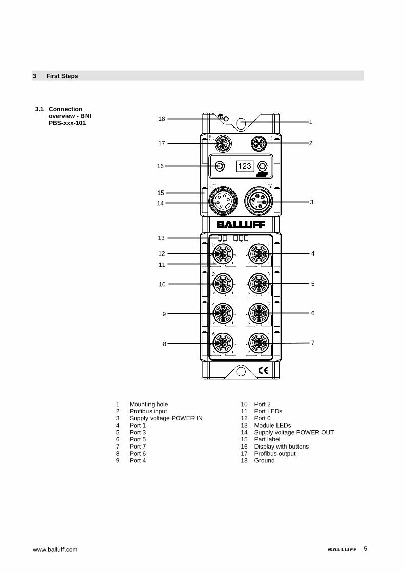
3.1 Connection overview - BNI PBS-xxx-101
1 Mounting hole
2 Profibus input 3 Supply voltage POWER IN 4 Port 1 5 Port 3 6 Port 5 7 Port 7 8 Port 6 9 Port 4
10 Port 2 11 Port LEDs 12 Port 0 13 Module LEDs 14 Supply voltage POWER OUT 15 Part label 16 Display with buttons 17 Profibus output 18 Ground
1
2
3
4
5
6
7 8
9
10
11
12
13
14
15
16
17
18
Balluff Network Interface Profibus BNI PBS-xxx-101-Z001
www.balluff.com 6
4 Basic knowledge
4.1 Product description
Balluff Network Interface BNI PBS-...: Used for connecting sensors/actuators to a Profibus-DP network. Sensors/actuators can be connected through eight standard I/O ports. Connection to Profibus using 2 × M12×1 round connectors. Electrical power 24 V DC using 7/8" round connector. Connection options: -BNI PBS-104-…: 16 standard inputs -BNI PBS-202-…: 8 standard outputs -BNI PBS-206-…: 16 standard outputs -BNI PBS-302-…: max. 16 standard inputs/outputs, freely configurable The main areas of application are:
• In the industrial sector as an interface between sensors/actuators and a Profibus. 4.2 Profibus Open bus system for process and field communication in cell networks with a low number
of stations as well as for data communication per IEC 61158/EN 50170. Automation devices such as PLCs, PCs, control and monitoring devices, sensors or actuators can communicate over this bus system. Variants:
• Profibus DP for fast, cyclical data exchange with field devices, • Profibus PA for applications in process automation in the intrinsically safe area, • Profibus FMS for data communication between automation devices and field
devices. 4.3 Replacing
modules The BNI PBS-... modules are upward compatible. A defective module can be replaced with
a module which has a greater or at least the same functionality.

www.balluff.com 7
5 Technical data
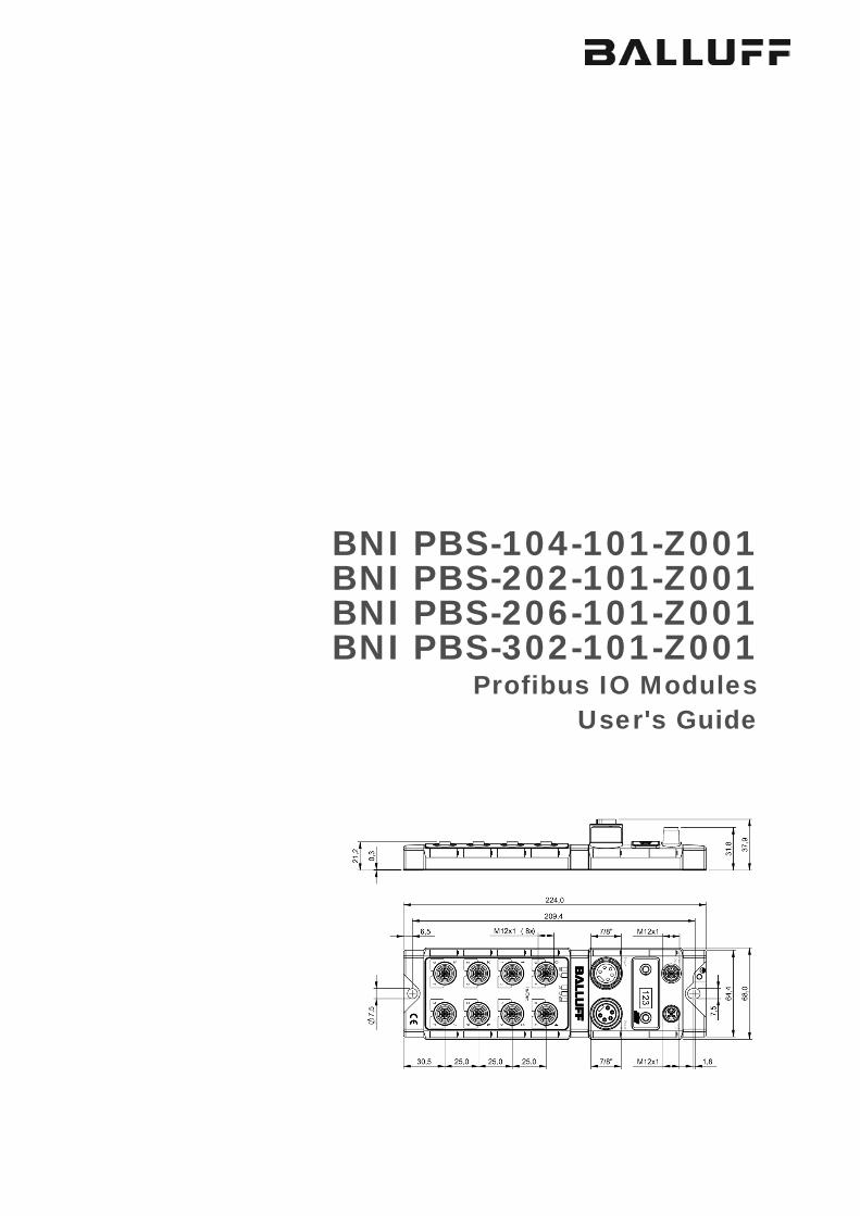
5.1 Dimensions
5.2 Mechanical data Housing material Die-case zinc, matte nickel plated
Fieldbus Profibus: M12, B-coded (male and female)
Supply voltage 5-pin, 7/8" (male and female)
I/O ports M12, A-coded (8x female)
Enclosure rating IP67 (only when plugged-in and screwed-in)
Weight approx. 735 g
5.3 Electrical data Operating voltage 18 ... 30 V DC
Ripple < 1 %
Current draw without load ≤ 200 mA
5.4 Operating
conditions Operating temperature
Storage temperature -5 C … 70°C -25 C … 70°C

Balluff Network Interface Profibus BNI PBS-xxx-101-Z001
www.balluff.com 8
6 Installation
6.1 Mechanical connection
The BNI PBS-... module can be connected directly to a mounting wall or to a machine. Be
sure that the mounting base is flat to prevent any mechanical stress on the device housing. Two M6 screws and two washers are required for mounting. The tightening torque is 9 Nm. Installation:
• Attach module using two M6 screws and two washers. • Keep a distance of at least 3 mm between two modules.
The BNI PBS-... is attached using two max. M6 screws and two washers.
Note Recommended hole dimension: 210.5 ±0.2 mm (when using M6 screws!). All IP67 Profibus/Profinet splitter boxes can be mounted when this hole diameter is used.
6.2 Electrical
connection The ground connection for the BNI PBS-... modules is located at upper left next to the
mounting hole. Ground straps are preferred for the ground connection. Alternately a fine-strand PE wire with large cross-section may be used.
Function ground
Note The FE connection from the housing to the machine must be low-impedance and kept as short as possible.

www.balluff.com 9
6 Installation
Supply voltage Profibus modules require a DC voltage of 24 V DC (SELF/PELF) for power. The power can be provided by regulated and unregulated power supplies. Regulated power supplies allow the output voltage to be increased above the nominal voltage to compensate for line losses.
Attention!
The use of a Profibus hybrid cable is not permitted. Power IN (7/8", 5-pin, male) Power OUT (7/8", 5-pin, female)
Pin Function 1 Ground 0 V 2 3 Function ground FE 4 Module and sensor supply +24V 5 Actuator supply +24V
• 24 V DC. • Use different power sources for the sensor/bus and for the actuator if possible to
minimize noise susceptibility. • Total current < 9 A. The total current of all modules may not exceed 9 A even
when daisy chaining the actuator supply.
Note Module and connected sensors are powered by the "module and sensor supply", while the "actuator supply" powers all outputs.
Note The sensor supply and actuator supply should be powered from different electricity sources wherever possible.

Balluff Network Interface Profibus BNI PBS-xxx-101-Z001
www.balluff.com 10
6 Installation
6.3 Bus connection The bus connection is made using the Profibus IN and Profibus OUT M12 sockets. The
address is set on the address switch.
Profibus OUT (M12, B-coded, female)
Profibus IN (M12, B-coded, male)
PIN Function
1 VP(+5V) 2 RxD/TxD-N, A line (green) 3 DGND 4 RxD/TxD-P, B line (red) 5 n.c.
Thread Shield/FE
Connection information Connect protective ground to FE Connect the incoming Profibus line to Profibus IN Connect the secondary Profibus line to Profibus OUT and connect to
downstream device or use terminating resistor.
Note Each Profibus segment must be terminated with a bus terminator. The terminating resistor requires no external voltage. Unused sockets must be fitted with cover caps to ensure IP 67 enclosure rating.
Attention! Pin 1 on the male connector (VP) is only required for the terminating resistors and is coupled via the Profibus. Any voltages connected directly to the pin may damage the module.
6.4 Ports Eight I/O ports are provided for connecting actuators and sensors.
The sensor supply is protected against short circuits and overload by a self-resetting PTC. When an overload or short circuit occurs at the output, the affected output is turned off. The output remains turned off after the fault is eliminated. The affected output must be turned off from the controller to clear the short circuit memory.
I/O ports Standard I/O port M12, A-coded, female
PIN Function 1 + 24 V, max. 200mA 2 Input / output max. 2A / diagnostics input 3 0 V / GND 4 Input / output max. 2A 5 FE
Note For the digital sensor inputs, the input guideline specified in EN 61131-2, Type 2 applies.
6.5 Replacing BNI
PBS modules • Turn off power to the Profibus module,
• remove the mounting screws, • replace the unit.

www.balluff.com 11
7 Startup
7.1 Profibus address The Profibus address is set directly on the BNI PBS-... using two buttons on the display. Permissible address range 0...125.
Addressing
Each Profibus node must have a unique address assigned to it. The address is loaded
once from the hard disk after the power is turned on. Any change to the address is saved immediately but does not become effective until power is reset on the module.
Menu structure The display on the BNI PBS-xxx-101-Z001 has the following menu structure. You can
navigate between the different menu items using the buttons.
Address setting The bus address is set on the display. Editing mode is activated if the "S" button is
pressed for longer than 3s. A flashing status value indicates that editing mode is active. In this case, pressing the " ↑ " button increases the value by one. When the required value is reached, the next status value can be selected by pressing the "S" button again. The value is changed by pressing the " ↑ " button. Pressing the "S" button in editing mode for more than approx. 10s saves the address currently selected. Although this address is saved, it is not yet active. The display LEDs and address flash to indicate that this status is active. The new address is only adopted after the power is reset. If no buttons are pressed in editing mode within 10 seconds, the module exits editing mode without saving the address. The display buttons can be locked by the PLC. A key symbol on the display indicates that this status is active.
7.2 Configuration When project planning Profibus devices, a device is mapped as a modular system which
consists of a header module and multiple data modules.
Current state Switch Condition: brief actuation of the Set button Condition: long actuation of the Set button Condition: brief actuation of the arrow button Flashing letter
Address changed
Editing mode

Balluff Network Interface Profibus BNI PBS-xxx-101-Z001
www.balluff.com 12
7 Startup
GSD file The device data required for project planning are stored in GSD files (Generic Station Description). The GSD files are available in 2 languages for downloading over the Internet (www.balluff.com).
Header module First the header module is inserted into the configuration. The header module is coded
according to the special identification format. Header modules with this coding are only used for identification and configuration and have a data width of 0 bytes.
Structure of the
header module Coding of the header module
Header module Description Coding BNI PBS-104-101-Z001 BNI DI16
01hex 52hex BNI PBS-202-101-Z001 BNI DO8 BNI PBS-206-101-Z001 BNI DO16 BNI PBS-302-101-Z001 BNI DI16DO16
Header byte
coding First byte of the header module (header byte)
Determining the inputs and/or outputs of the module Bit layout of header byte
7 6 5 4 3 2 1 0 0 0 Number of manufacturer-specific bytes:
(0: none, 1…14: number of bytes, 15: 16 bytes or words)
Header special format Determining inputs/outputs of the module: 0 0 Empty 0 1 Ports are inputs, 1 length-byte for input data 1 0 Ports are outputs, 1 length-byte for output data 1 1 Ports may be inputs or outputs, each 1 length-byte for output and
input data
Data modules Data modules are strung on to the header module in any sequence. Each data module
contains 1 byte of process data. Data module
coding Input modules
Data module Bit assignment Coding Input/Read back Pin 4 41hex 00hex 01hex Input/Diagnostic/Read back Pin 2 41hex 00hex 02hex Station diagnostic 41hex 00hex 03hex Periphery error on port 41hex 00hex 04hex Sensor supply short circuit 41hex 00hex 05hex Actuator shutdown Pin 4 41hex 00hex 06hex Actuator shutdown Pin 2 41hex 00hex 07hex Actuator warning Pin 4 41hex 00hex 08hex Actuator warning Pin 2 41hex 00hex 09hex
Output modules
Data module Bit assignment Coding Outputs Pin 4 81hex 00hex 0Ahex Outputs Pin 2 81hex 00hex 0Bhex Restart Pin 4 81hex 00hex 0Chex Restart Pin 2 81hex 00hex 0Dhex
Display Control 81hex 00hex 0Ehex
Note
Project planning software offers mostly graphical assistance in configuration; the configuration string is automatically created.

www.balluff.com 13
7 Startup
Process data
coding
Bit 7 6 5 4 3 2 1 0
Port 7, Channel
14
Port 6, Channel
12
Port 5, Channel
10
Port 4, Channel 8
Port 3, Channel 6
Port 2, Channel 4
Port 1, Channel 2
Port 0, Channel 0
Bit 7 6 5 4 3 2 1 0
Port 7, Channel
15
Port 6, Channel
13
Port 5, Channel
11
Port 4, Channel 9
Port 3, Channel 7
Port 2, Channel 5
Port 1, Channel 3
Port 0, Channel 1
Bit 7 6 5 4 3 2 1 0
- Actuator warning
Actuator short circ.
Sensor short circ.
External error
None UA
Undervolt. UA
Undervolt. US
Bit 7 6 5 4 3 2 1 0
Port 7, Ch.
Port 6 Port 5 Port 4 Port 3 Port 2 Port 1 Port 0
Bit 7 6 5 4 3 2 1 0
- - - - - - Green LED on
Red LED on

Balluff Network Interface Profibus BNI PBS-xxx-101-Z001
www.balluff.com 14
7 Startup
7.3 Parameter configuration
The BNI PBS modules differ in how their I/O ports are configured:
Module Port Pin Channel Function BNI PBS-104- 0…7 4 00, 02, 04, 06,
08, 10, 12, 14 Input with N.O. function or input with N.C. function
0…7 2 01, 03, 05, 07, 09, 11, 13, 15
Input with N.O. function or input with N.C. function or diagnostics input (N.C. function)
BNI PBS-202- 0…7 4 00, 02, 04, 06, 08, 10, 12, 14
Output
BNI PBS-206- 0…7 4 00, 02, 04, 06, 08, 10, 12, 14
Output
0…7 2 01, 03, 05, 07, 09, 11, 13, 15
Output
BNI PBS-302- 0…7 4 00, 02, 04, 06, 08, 10, 12, 14
Input with N.O. function or input with N.C. function Output
0…7 2 01, 03, 05, 07, 09, 11, 13, 15
Input with N.O. function or input with N.C. function or diagnostics input (N.C. function) Output
Some parameters have four selection options. These parameters are represented by two bits each (values 0dec to 3dec).
Note
Coding of the function of pin 2 and pin 4 is not identical.
Parameter setting
of the standard I/O ports
Pin 4 functions:
Decimal Bit 1 Bit 0 Function 0 0 0 Input – N.O. function (for BNI PBS-202/206... reserved) 1 0 1 Input – N.C. function (for BNI PBS-202/206…reserved) 2 1 0 Output (for BNI PBS-104-101… reserved) 3 1 1 Reserved
Functions Pin 2: (only for BNI PBS-104… and BNI PBS-302…)
Decimal Bit 1 Bit 0 Function 0 0 0 Input – N.O. function (for BNI PBS-202/206 reserved) 1 0 1 Input – N.C. function (for BNI PBS-202/206 reserved) 2 1 0 Diagnostics input (N.C.) 3 1 1 Output (for BNI PBS-104-101 reserved.)
Safe state: The "safe state“ function can only be configured for standard outputs. (not possible for BNI PBS-104-…)
Decimal Bit 1 Bit 0 Function 0 0 0 "0" output is switched off (0V) 1 0 1 "1" output is switched on (+24V) 2 1 0 Last state – the last state of the output is preserved 3 1 1 Reserved
www.balluff.com 15
7 Startup
7.4 Parameter configuration
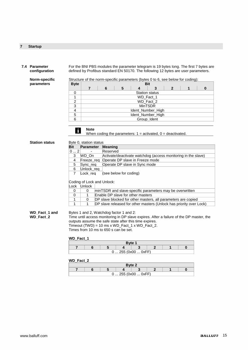
For the BNI PBS modules the parameter telegram is 19 bytes long. The first 7 bytes are defined by Profibus standard EN 50170. The following 12 bytes are user parameters.
Norm-specific
parameters Structure of the norm-specific parameters (bytes 0 to 6, see below for coding):
Byte Bit 7 6 5 4 3 2 1 0
0 Station status 1 WD_Fact_1 2 WD_Fact_2 3 MinTSDR 4 Ident_Number_High 5 Ident_Number_High 6 Group_Ident
Note
When coding the parameters: 1 = activated, 0 = deactivated.
Station status Byte 0, station status
Bit Parameter Meaning 0 ... 2 - Reserved
3 WD_On Activate/deactivate watchdog (access monitoring in the slave) 4 Freeze_req Operate DP slave in Freeze mode 5 Sync_req Operate DP slave in Sync mode 6 Unlock_req
(see below for coding) 7 Lock_req Coding of Lock and Unlock: Lock Unlock
0 0 minTSDR and slave-specific parameters may be overwritten 0 1 Enable DP slave for other masters 1 0 DP slave blocked for other masters, all parameters are copied 1 1 DP slave released for other masters (Unlock has priority over Lock)
WD_Fact_1 and
WD_Fact_2 Bytes 1 and 2, Watchdog factor 1 and 2:
Time until access monitoring in DP slave expires. After a failure of the DP master, the outputs assume the safe state after this time expires. Timeout (TWD) = 10 ms x WD_Fact_1 x WD_Fact_2. Times from 10 ms to 650 s can be set. WD_Fact_1
Byte 1 7 6 5 4 3 2 1 0
0 ... 255 (0x00 ... 0xFF) WD_Fact_2
Byte 2 7 6 5 4 3 2 1 0
0 ... 255 (0x00 ... 0xFF)

Balluff Network Interface Profibus BNI PBS-xxx-101-Z001
www.balluff.com 16
7 Startup
MinTSDR MinTSDR: Minimum time before sending a slave reply (in Tbits). The standard prescribes a minimum value of 11 Tbits. The value must be less than MaxTSDR.
Byte 1 7 6 5 4 3 2 1 0
0, 11 ... 255 (0x00, 0x0B ... 0xFF)
Ident_Number-
_High Ident_Number_High: Identification number high-byte
Byte 1 7 6 5 4 3 2 1 0
0 ... 255 (0x00 ... 0xFF)
Ident_Number-
_Low Ident_Number_Low: Identification number low-byte
Byte 1 7 6 5 4 3 2 1 0
0 ... 255 (0x00 ... 0xFF)
Group_Ident Group_Ident: Group number of the BNI PBS-Module.
Each bit represents a group. Is only applied if Lock_Req is activated. Byte 1
7 6 5 4 3 2 1 0 Group 8 Group 7 Group 6 Group 5 Group 4 Group 3 Group 2 Group 1

www.balluff.com 17
7 Startup
User parameters
The BNI PBS modules differ in how the functions are set for the ports. The user parameters have the same structure for all modules. Parameters which are not supported by a module are indicated as reserved. Reserved parameters must be written with the value 0. Bytes 7 to 9 of the user parameters are reserved and can be ignored. The required settings are made using the user parameters beginning with byte 10.
BNI PBS-104-… Bytes in
telegram Meaning
0 to 6 Norm-specific parameters (see above) 7 Reserved 8 Reserved 9 Reserved 10 Global settings 11 Function Port 0…3 Pin 4 (Channel 00, 02, 04, 06) 12 Function Port 4…7 Pin 4 (Channel 08, 10, 12, 14) 13 Function Port 0…3 Pin 2 (Channel 01, 03, 05, 07) 14 Function Port 4…7 Pin 2 (Channel 09, 11, 13, 15) 15 Reserved 16 Reserved 17 Reserved 18 Reserved
BNI PBS-202-… Bytes in
telegram Meaning
0 to 6 Norm-specific parameters (see above) 7 Reserved 8 Reserved 9 Reserved 10 Global settings 11 Reserved 12 Reserved 13 Reserved 14 Reserved 15 Safe State Port 0…3 Pin 4 (Channel 00, 02, 04, 06) 16 Safe State Port 4…7 Pin 4 (Channel 08, 10, 12, 14) 17 Reserved 18 Reserved
BNI PBS-206-… Bytes in
telegram Meaning
0 to 6 Norm-specific parameters (see above) 7 Reserved 8 Reserved 9 Reserved 10 Global settings 11 Reserved 12 Reserved 13 Reserved 14 Reserved 15 Safe State Port 0…3 Pin 4 (Channel 00, 02, 04, 06) 16 Safe State Port 4…7 Pin 4 (Channel 08, 10, 12, 14) 17 Safe State Port 0…3 Pin 2 (Channel 01, 03, 05, 07) 18 Safe State Port 4…7 Pin 2 (Channel 09, 11, 13, 15)

Balluff Network Interface Profibus BNI PBS-xxx-101-Z001
www.balluff.com 18
7 Startup
BNI PBS-302-… Bytes in
telegram Meaning
0 to 6 Norm-specific parameters (see above) 7 Reserved 8 Reserved 9 Reserved 10 Global settings 11 Function Port 0…3 Pin 4 (Channel 00, 02, 04, 06) 12 Function Port 4…7 Pin 4 (Channel 08, 10, 12, 14) 13 Function Port 0…3 Pin 2 (Channel 01, 03, 05, 07) 14 Function Port 4…7 Pin 2 (Channel 09, 11, 13, 15) 15 Safe State Port 0…3 Pin 4 (Channel 00, 02, 04, 06) 16 Safe State Port 4…7 Pin 4 (Channel 08, 10, 12, 14) 17 Safe State Port 0…3 Pin 2 (Channel 01, 03, 05, 07) 18 Safe State Port 4…7 Pin 2 (Channel 09, 11, 13, 15)
Coding the user
parameters
Global settings Byte 10
Bit Meaning 0 Enable/block diagnostics messages 1 Enable/block channel-specific diagnostics 2 Enable/block diagnostics for undervoltage of sensor/bus supply 3 Enable/block diagnostics for undervoltage of actuators* 4 Enable/block diagnostics for Us short circuit at outputs** 5 Enable/block editing of the address 6 Reserved 7 Reserved
* for BNI-PBS-104-… reserved ** only for BNI PBS-302-…
Note
When coding the settings: 1 = enabled, 0 = blocked.
Function Port 0…3 (Channel 00, 02, 04, 06)
Byte 11 Bit Meaning 0 Function Port 0, Pin 4 (Channel 00) 1 2 Function Port 1, Pin 4 (Channel 02) 3 4 Function Port 2, Pin 4 (Channel 04) 5 6 Function Port 3, Pin 4 (Channel 06) 7

www.balluff.com 19
7 Startup
Function Port 4…7 (Channel 08, 10, 12, 14)
Byte 12 Bit Meaning 0 Function Port 4, Pin 4 (Channel 08) 1 2 Function Port 5, Pin 4 (Channel 10) 3 4 Function Port 6, Pin 4 (Channel 12) 5 6 Function Port 7, Pin 4 (Channel 14) 7
Function Port 0…3 (Channel 01, 03, 05, 07)
Byte 13 Bit Meaning 0 Function Port 0, Pin 2 (Channel 01) 1 2 Function Port 1, Pin 2 (Channel 03) 3 4 Function Port 2, Pin 2 (Channel 05) 5 6 Function Port 3, Pin 2 (Channel 07) 7
Function Port 4…7 (Channel 09, 11, 13, 15)
Byte 14 Bit Meaning 0 Function Port 4, Pin 2 (Channel 09) 1 2 Function Port 5, Pin 2 (Channel 11) 3 4 Function Port 6, Pin 2 (Channel 12) 5 6 Function Port 7, Pin 2 (Channel 15) 7
Note
For BNI PBS-202/206-…bytes 11 to 14 are reserved
Safe State Port 0…3 (Channel 00, 02, 04, 06)
Byte 15 Bit Meaning 0 Safe State Port 0, Pin 4 (Channel 00) 1 2 Safe State Port 1, Pin 4 (Channel 02) 3 4 Safe State Port 2, Pin 4 (Channel 04) 5 6 Safe State Port 3, Pin 4 (Channel 06) 7

Balluff Network Interface Profibus BNI PBS-xxx-101-Z001
www.balluff.com 20
7 Startup
Safe State Port 4…7 (Channel 08, 10, 12, 14)
Byte 16 Bit Meaning 0 Safe State Port 4, Pin 4 (Channel 08) 1 2 Safe State Port 5, Pin 4 (Channel 10) 3 4 Safe State Port 6, Pin 4 (Channel 12) 5 6 Safe State Port 7, Pin 4 (Channel 14) 7
Safe State Port 0…3 (Channel 01, 03, 05, 07)
Byte 17 Bit Meaning 0 Safe State Port 0, Pin 2 (Channel 01) 1 2 Safe State Port 1, Pin 2 (Channel 03) 3 4 Safe State Port 2, Pin 2 (Channel 05) 5 6 Safe State Port 3, Pin 2 (Channel 07) 7
Safe State Port 4…7 (Channel 09, 11, 13, 15)
Byte 18 Bit Meaning 0 Safe State Port 4, Pin 2 (Channel 09) 1 2 Safe State Port 5, Pin 2 (Channel 11) 3 4 Safe State Port 6, Pin 2 (Channel 12) 5 6 Safe State Port 7, Pin 2 (Channel 15) 7
Note
Bytes 15 to 18 are reserved for the BNI PBS-104-… Bytes 13 to 14 and 17 to 18 are reserved for the BNI PBS-202-…

www.balluff.com 21
7 Startup
7.5 Integration in project planning software
The example shows the connection of the BNI PBS modules to a Siemens S7 controller with "SIMATIC Manager". The exact procedure depends on the project planning software used
Installing the
GSD file To perform project planning on the PC, the GSD file for the module must be installed:
Open a new project. Open hardware configurator. Select menu command "Tools | Install new GSD...". The window "Install new GSD" opens. Select directory and GSD file. The [Install] button only becomes active if a GSD file is selected. Click on [Install]. The GSD file is installed. When the process is finished, a message appears. Confirm the message and close the window. Select the menu command "Tools | Update catalog". The modules are displayed in the project tree.

Balluff Network Interface Profibus BNI PBS-xxx-101-Z001
www.balluff.com 22
7 Startup
Prerequisite To integrate the Profibus slave, a functioning configuration of the PLC and of DP interface is necessary.
Integrating the
module The modules are located in the hardware catalog under "Other field devices“. The module is
added as a DP slave. • Select the Profibus rail. • Double-clicking adds the module as a DP slave.
www.balluff.com 23
7 Startup
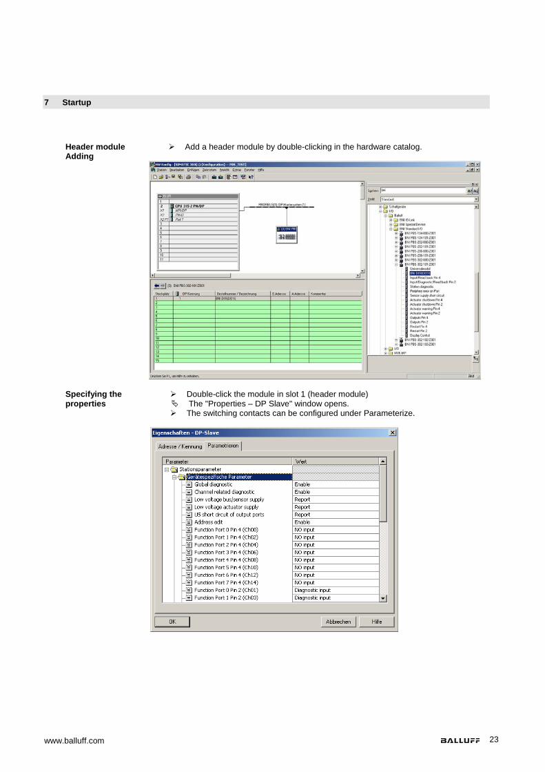
Header module Adding
Add a header module by double-clicking in the hardware catalog.
Specifying the
properties Double-click the module in slot 1 (header module)
The "Properties – DP Slave" window opens. The switching contacts can be configured under Parameterize.

Balluff Network Interface Profibus BNI PBS-xxx-101-Z001
www.balluff.com 24
7 Startup
Configuring inputs or outputs
Under "Parameter" select port and pin. In the list field click on "Value". The possible functions for the selected port and pin are displayed. Select the function.
Configuring the
slots Additional data modules can be selected and configured from the hardware catalog.
Example:
Note
If the Restart Pin x modules are not selected, the outputs are automatically restarted in the event of a short circuit
www.balluff.com 25
8 Diagnostics
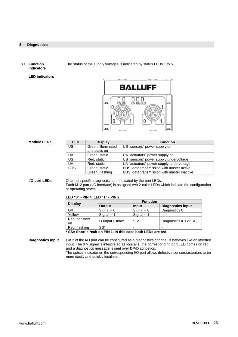
8.1 Function Indicators
The status of the supply voltages is indicated by status LEDs 1 to 5.
LED indicators
Module LEDs LED Display Function
US Green, illuminated and stays on
US "sensors" power supply on
UA Green, static UA "actuators" power supply on US Red, static US "sensors" power supply undervoltage UA Red, static UA "actuators" power supply undervoltage BUS Green, static
Green, flashing BUS, data transmission with master active BUS, data transmission with master inactive
I/O port LEDs Channel-specific diagnostics are indicated by the port LEDs.
Each M12 port (I/O interface) is assigned two 2-color LEDs which indicate the configuration or operating states. LED "0" - PIN 4, LED "1" - PIN 2
Display Function Output Input Diagnostics input
Off Signal = 0 Signal = 0 Diagnostics 0 Yellow Signal = 1 Signal = 1 Red, constant on I Output > Imax SS* Diagnostics = 1 or SC
Red, flashing SS* - - * SS= Short circuit on PIN 1. In this case both LEDs are red.
Diagnostics input Pin 2 of the I/O port can be configured as a diagnostics channel. It behaves like an inverted
input. The 0 V signal is interpreted as logical 1, the corresponding port LED comes on red and a diagnostics message is sent over DP-Diagnostics. The optical indicator on the corresponding I/O port allows defective sensors/actuators to be more easily and quickly localized.

Balluff Network Interface Profibus BNI PBS-xxx-101-Z001
www.balluff.com 26
8 Diagnostics
8.2 Diagnostics telegram
The diagnostics telegram comprises various blocks. The first 6 bytes are defined by the Profibus standard EN 50170. The following 4 bytes are device-specific and ID-specific diagnostics information (2 bytes each). For each channel-specific diagnostic, 3 bytes of diagnostics information are added (min. 6 and max. 244 bytes).
8.3 Norm diagnostics Byte Bit
7 6 5 4 3 2 1 0 0 Status 1 1 Status 2 2 Status 3 3 Master address 4 Indent_Number_High_Byte: 0Bhex 5 Indent_Number_Low_Byte: 1Ahex
Note The following applies for the coding of norm-specific diagnostics: 1 = activated, 0 = deactivated
Norm diagnostics
coding In the following, the coding of bytes 0 to 3 of the norm diagnostics is described.
Byte 4 and byte 5 (identification number) are fixed. Status 1 Byte 0, status 1
Bit Meaning 0 Station_non_existent
The DP slave always sets the bit to 0. The DP master sets it to 1 if the DP slave cannot be reached.
1 Station_not_ready The DP slave sets the bit to 1 if it is not yet ready for data exchange.
2 Cfg_Fault The DP slave sets the bit to 1 if the configuration data last received from the master do not agree with those which the DP slave determined.
3 Ext_diag If the bit is set to 1, there is a diagnostics entry in the slave-specific diagnostics area (Ext_Diag_Data). A further diagnostic follows in the telegram.
4 Not supported The DP slave sets the bit to 1 if a function was requested which is not supported.
5 Invalid_Slave-Response The DP slave always sets the bit to 0. The DP master sets it to 1 if the DP slave sends an implausible response.
6 Prm_fault The DP slave sets the bit to 1 if the last parameter telegram was incorrect (e.g. incorrect length, incorrect identification number, invalid parameters).
7 Master_lock The DP slave always sets the bit to 0. The DP master sets it to 1 if the DP slave was parameterized by a different master (Lock from another master, here: address in byte 3 not equal to FFhex and not equal to its own address).

www.balluff.com 27
8 Diagnostics
Status 2 Byte 1, status 2 Bit Meaning 0 Prm_req
The DP slave always sets the bit to 1 if it needs to be reconfigured and parameterized. The bit remains set until parameterization has been performed.
1 Stat_Diag (static diagnostic) The slave sets the bit to 1 if, for example, it can´t + send valid data. In this case the DP master retrieves diagnostic data until the bit is reset to 0.
2 Fixed at 1 3 WD_On
Monitoring activated/deactivated (Watchdog on). 4 Freeze_Mode
The slave sets the bit to 1 if it has received the Freeze command. 5 Sync_Mode
The slave sets the bit to 1 if it has received the Sync command. 6 Not_Present
The DP slave always sets the bit to 0. The DP master sets it to 1 for the DP slaves that are not included in the master parameter set.
7 Deactivated The DP slave always sets the bit to 0. The DP master sets it to 1 if the DP slave is removed from the master parameter set.
Status 3 Byte 2, status 3
Bit Meaning 0 ... 6 Reserved
7 Ext_Diag_Overflow If this bit is set, there is more diagnostics information than indicated in Ext_Diag_Data. For example, the DP slave sets the bit to 1 if there is more channel-specific diagnostics information than the DP slave can enter in its send buffer. A DP master sets the bit to 1 if the DP slave sends more diagnostics information than the master can hold in its diagnostics buffer.
Address Byte 3, address of the master:
Bit Meaning 0 ... 7 Master_Add
After parameterizing, the address of the DP master which has parameterized the DP slave is entered. If the DP slave has not been parameterized by a master, it sets address FFhex.
Ident_Number_High_Byte Byte 4, Ident High
Bit Meaning 0 ... 7 BNI PBS-…-101-...: 0Dhex
Ident_Number_Low_Byte Byte 5, Ident Low
Bit Meaning 0 ... 7 BNI PBS-104-101-...: 92hex
BNI PBS-202-101-...: 91hex BNI PBS-206-101-…: 90hex BNI PBS-302-101-...: 8Fhex

Balluff Network Interface Profibus BNI PBS-xxx-101-Z001
www.balluff.com 28
8 Diagnostics
8.4 Device-specific diagnostics
Bytes 6 and 7 in the diagnostics telegram, device-specific diagnostics:
Byte Bit 7 6 5 4 3 2 1 0
Header 6 0 0 Device-specific header byte: Number of bytes in the device-specific diagnostics (incl. header byte)
Device block 7 - Actuator
warning Actuator turn-off
Sensor short circuit
External error
None UA UA US
UA: Undervoltage, actuator supply; US: Undervoltage, sensor and bus supply
Note The following applies for the coding of device-specific diagnostics: 1 = activated, 0 = deactivated
ID-specific
diagnostics Bytes 8 and 9 in diagnostics telegram, ID-specific diagnostics
Byte Bit
7 6 5 4 3 2 1 0
Header 8 0 0 ID-specific header byte: Number of bytes in the ID-specific diagnostic (incl. header byte)
Module-specific.
diagnostics 9 Ident number of the module
Channel-specific
diagnostics Bytes 10 to 12 in diagnostics telegram, channel-specific diagnostics
For each channel-specific diagnosis, three bytes of diagnostics information are added with the following coding.
Byte Bit 7 6 5 4 3 2 1 0
10 1 0 Ident number
11
Channel number (from port/pin) 0 0 Reserved 0 1 Input 1 0 Output 1 1 Input and output
12
Error type: 01hex: Short circuit, sensor supply 02hex: Undervoltage 17hex: Actuator warning 18hex: Actuator turn-off 1Ahex: External error 0 0 0 Reserved 0 0 1 Bit 0 1 0 2 bit 0 1 1 4 bit 1 0 0 Byte 1 0 1 Word 1 1 0 2 words 1 1 1 Reserved

www.balluff.com 29
8 Diagnostics
Possible channel-specific diagnostics
Sensor supply short circuit (pin configured as input): Port Pin Channel 1st byte 2nd byte 3rd byte 0 4 0 80hex 40hex 21hex
2 1 80hex 41hex 21hex 1 4 2 80hex 42hex 21hex
2 3 80hex 43hex 21hex 2 4 4 80hex 44hex 21hex
2 5 80hex 45hex 21hex 3 4 6 80hex 46hex 21hex
2 7 80hex 47hex 21hex 4 4 8 80hex 48hex 21hex
2 9 80hex 49hex 21hex 5 4 10 80hex 4Ahex 21hex
2 11 80hex 4Bhex 21hex 6 4 12 80hex 4Chex 21hex
2 13 80hex 4Dhex 21hex 7 4 14 80hex 4Ehex 21hex
2 15 80hex 4Fhex 21hex
Sensor supply short circuit (pin configured as output, only for BNI PBS-302-...):
Port Pin Channel 1st byte 2nd byte 3rd byte 0 4 0 80hex 80hex 21hex
2 1 80hex 81hex 21hex 1 4 2 80hex 82hex 21hex
2 3 80hex 83hex 21hex 2 4 4 80hex 84hex 21hex
2 5 80hex 85hex 21hex 3 4 6 80hex 86hex 21hex
2 7 80hex 87hex 21hex 4 4 8 80hex 88hex 21hex
2 9 80hex 89hex 21hex 5 4 10 80hex 8Ahex 21hex
2 11 80hex 8Bhex 21hex 6 4 12 80hex 8Chex 21hex
2 13 80hex 8Dhex 21hex 7 4 14 80hex 8Ehex 21hex
2 15 80hex 8Fhex 21hex
Actuator warning (pin configured as output, except for BNI PBS-104-...):
Port Pin Channel 1st byte 2nd byte 3rd byte 0 4 0 80hex 80hex 37hex
2 1 80hex 81hex 37hex 1 4 2 80hex 82hex 37hex
2 3 80hex 83hex 37hex 2 4 4 80hex 84hex 37hex
2 5 80hex 85hex 37hex 3 4 6 80hex 86hex 37hex
2 7 80hex 87hex 37hex 4 4 8 80hex 88hex 37hex
2 9 80hex 89hex 37hex 5 4 10 80hex 8Ahex 37hex
2 11 80hex 8Bhex 37hex 6 4 12 80hex 8Chex 37hex
2 13 80hex 8Dhex 37hex 7 4 14 80hex 8Ehex 37hex
2 15 80hex 8Fhex 37hex

Balluff Network Interface Profibus BNI PBS-xxx-101-Z001
www.balluff.com 30
8 Diagnostics
Actuator turn-off (pin configured as output, except for BNI PBS-104-…) Port Pin Channel 1st
byte 2nd byte
3rd byte
0 4 0 80hex 80hex 38hex 2 1 80hex 81hex 38hex
1 4 2 80hex 82hex 38hex 2 3 80hex 83hex 38hex
2 4 4 80hex 84hex 38hex 2 5 80hex 85hex 38hex
3 4 6 80hex 86hex 38hex 2 7 80hex 87hex 38hex
4 4 8 80hex 88hex 38hex 2 9 80hex 89hex 38hex
5 4 10 80hex 8Ahex 38hex 2 11 80hex 8Bhex 38hex
6 4 12 80hex 8Chex 38hex 2 13 80hex 8Dhex 38hex
7 4 14 80hex 8Ehex 38hex 2 15 80hex 8Fhex 38hex
External error (pin configured as diagnostics input)
Port Pin Channel 1st byte
2nd byte
3rd byte
0 2 1 80hex 41hex 3Ahex 1 2 3 80hex 43hex 3Ahex 2 2 5 80hex 45hex 3Ahex 3 2 7 80hex 47hex 3Ahex 4 2 9 80hex 49hex 3Ahex 5 2 11 80hex 4Bhex 3Ahex 6 2 13 80hex 4Dhex 3Ahex 7 2 15 80hex 4Fhex 3Ahex

www.balluff.com 31
9 Appendix
9.1 Scope of delivery The BNI EIP consists of the following components: • IO block • 4 blind plugs M12 • Ground strap • Screw M4x6 • 20 labels
9.2 Order code BNI PBS-xxx-101-Z001
Balluff Network Interface Profibus Function 104 = IP67 IO modules, 16 x standard inputs 202 = IP67 IO modules, 8 x standard outputs 206 = IP67 IO modules, 16 x standard outputs 302 = IP67 IO modules, 16 x standard inputs/outputs, freely configurable Variants 101 = display version Mechanical version Z001 = Material die-cast zinc, matte nickel plated Bus connection: 1 x M12x1 internal thread, 1x M12x1 external thread Supply voltage: 7/8" male thread IO ports: 8 x M12x1 internal thread
9.3 Ordering
information Type designation code Order code
BNI PBS-104-101-Z001 BNI005C BNI PBS-202-101-Z001 BNI0057 BNI PBS-206-101-Z001 BNI0069 BNI PBS-302-101-Z001 BNI0047

Balluff Network Interface Profibus BNI PBS-xxx-101-Z001
www.balluff.com 32
9 Appendix
9.4 ASCII table Decimal Hex Control
code ASCII Decimal Hex ASCII Decimal Hex ASCII
0 00 Ctrl @ NUL 43 2B + 86 56 V 1 01 Ctrl A SOH 44 2C , 87 57 W 2 02 Ctrl B STX 45 2D - 88 58 X 3 03 Ctrl C ETX 46 2E . 89 59 Y 4 04 Ctrl D EOT 47 2F / 90 5 A Z 5 05 Ctrl E ENQ 48 30 0 91 5B [ 6 06 Ctrl F ACK 49 31 1 92 5C \ 7 07 Ctrl G BEL 50 32 2 93 5D [ 8 08 Ctrl H BS 51 33 3 94 5E ^ 9 09 Ctrl I HT 52 34 4 95 5F _ 10 0 A Ctrl J LF 53 35 5 96 60 ` 11 0B Ctrl K VT 54 36 6 97 61 A 12 0C Ctrl L FF 55 37 7 98 62 B 13 0D Ctrl M CR 56 38 8 99 63 c 14 0E Ctrl N SO 57 39 9 100 64 d 15 0F Ctrl O SI 58 3 A : 101 65 e 16 10 Ctrl P DLE 59 3B ; 102 66 f 17 11 Ctrl Q DC1 60 3C < 103 67 g 18 12 Ctrl R DC2 61 3D = 104 68 h 19 13 Ctrl S DC3 62 3E > 105 69 i 20 14 Ctrl T DC4 63 3F ? 106 6 A j 21 15 Ctrl U NAK 64 40 @ 107 6B k 22 16 Ctrl V SYN 65 41 A 108 6C L 23 17 Ctrl W ETB 66 42 B 109 6D m 24 18 Ctrl X CAN 67 43 C 110 6E n 25 19 Ctrl Y EM 68 44 D 111 6F o 26 1 A Ctrl Z SUB 69 45 E 112 70 p 27 1B Ctrl [ ESC 70 46 F 113 71 q 28 1C Ctrl \ FS 71 47 G 114 72 r 29 1D Ctrl ] GS 72 48 H 115 73 s 30 1E Ctrl ^ RS 73 49 I 116 74 t 31 1F Ctrl _ US 74 4 A J 117 75 u 32 20 SP 75 4B K 118 76 V 33 21 ! 76 4C L 119 77 W 34 22 „ 77 4D M 120 78 X 35 23 # 78 4E N 121 79 Y 36 24 $ 79 4F O 122 7 A Z 37 25 % 80 50 P 123 7B { 38 26 & 81 51 Q 124 7C | 39 27 ‘ 82 52 R 125 7D } 40 28 ( 83 53 S 126 7E ~ 41 29 ) 84 54 T 127 7F DEL 42 2 A * 85 55 U

www.balluff.com
www.balluff.com
Balluff GmbH Schurwaldstrasse 9 73765 Neuhausen a.d.F. Germany Tel. +49 7158 173-0 Fax +49 7158 5010 [email protected]
No.
894
353-
726
EN
•01
.125
152
• E
ditio
n J1
7 •
Rep
lace
s Ed
ition
130
1 •
Sub
ject
to m
odifi
catio
ns
Related Documents