User's and maintenance manual [email protected] www.electricmotorsmt.com M.T. Motori Elettrici Srl Via Bologna n. 175 40017 San Giovanni in Persiceto (BO) Cod.Fisc. e P.IVA: 00863511200 / REA 407664 Tel. 051/6875011 Fax 051/6871455 1 Data contained in this manual are indicative, not binding and can be modified without prior notification by MT Motori Elettrici. MT MOTORI ELETTRICI Installation, operation and maintenance manual for low voltage motors TABLE OF CONTENTS I. Introduction: scope of application; safety; reception and storage; installation; maintenance and spare parts; disposal II. Electric connection III. IE2/IE3 IV. Brake motors V. ATEX and UL certificates VI. Inverter use EC Declaration of Conformity

Welcome message from author
This document is posted to help you gain knowledge. Please leave a comment to let me know what you think about it! Share it to your friends and learn new things together.
Transcript

User's and maintenance manual [email protected]
www.electricmotorsmt.com
M.T. Motori Elettrici Srl
Via Bologna n. 175
40017 San Giovanni in Persiceto (BO)
Cod.Fisc. e P.IVA: 00863511200 / REA 407664
Tel. 051/6875011 Fax 051/6871455
1 Data contained in this manual are indicative, not binding and can be modified without prior notification by MT Motori Elettrici.
MT MOTORI ELETTRICI
Installation, operation and maintenance manual for low voltage
motors
TABLE OF CONTENTS
I. Introduction: scope of application; safety; reception and storage; installation;
maintenance and spare parts; disposal
II. Electric connection
III. IE2/IE3
IV. Brake motors
V. ATEX and UL certificates
VI. Inverter use
EC Declaration of Conformity

User's and maintenance manual [email protected]
www.electricmotorsmt.com
M.T. Motori Elettrici Srl
Via Bologna n. 175
40017 San Giovanni in Persiceto (BO)
Cod.Fisc. e P.IVA: 00863511200 / REA 407664
Tel. 051/6875011 Fax 051/6871455
2 Data contained in this manual are indicative, not binding and can be modified without prior notification by MT Motori Elettrici.
I – Introduction
The instructions contained in this manual refer to MT Motori Elettrici threephase and single phase
asynchronous motors, with or without brake, under following designations TN, DN, MN, XN, TF, DF, MF, XF,
TFP, MFP, XFP DFP, TFS, DFS, MFS, XFS, sizes 56 to 200. For further information visit the website
www.electricmotorsmt.com.
1.1 Scope of application
MT Motori Elettrici motors are designed and built to operate, according to the data on the plate, in
environments with temperature between -20 °C and 40 °C; maximum altitude 1000 m above sea level;
tolerance for voltage supply +/- 5% and for frequency +/- 2% (EN 60034-1). Only use the motor for the
applications it was designed and built for. Comply with data on the plate. Non-compliance with the
instructions provided in this manual and with the reference standards may make the motor not suitable for
the foreseen use. Always comply with the prescriptions in order not to compromise safety. For any other
use in environments with different temperature, or at an altitude higher than 1000 m above sea level,
contact MT Motori Elettrici. In case of motors to be used in hazardous areas and explosive atmospheres
due to the presence of gas or dust, refer to the ATEX 2014/34/UE European directive and order motors
specifically designed, built and tested in compliance with the aforementioned directive, related updates
and following (see chapter V).
1.2 Safety
Motor installation, maintenance and disposal must be carried out by skilled staff, in compliance with the
user’s and maintenance manual. MT Motori Elettrici provides this manual on the website
www.electricmotorsmt.com, section Download - Operating Instructions and User's Manual.
WARNING: The electric motor is an electric rotating device and it is therefore supplied with moving parts
and can reach high temperature. The motor is designed to be combined with other devices or machinery
and it should never be operated if the device or the machinery does not comply with 2006/95/CE (Low
voltage directive); 2006/42/CE (Machinery directive); 2004/108/CE (electromagnetic compatibility
directive). It is necessary to comply with the aforementioned directives and following updates, and with the
current regulations. Operations on the motor must be carried out when the device is not operating nor
connected to the power network. Should clarifications be necessary or, in any event, in case of doubt,
contact MT Motori Elettrici.
1.3 Reception and storage
Always check the information written in the technical documents and make sure it matches the features of
the environment where the motor will be installed. MT Motori Elettrici supplies tested motors, which are
ready to be installed.
It is recommended to check the motor upon reception in order to make sure there are no transport
damages. Do not operate motors that display damages or are not considered suitable for the intended use.
In case of doubt, contact MT Motori Elettrici. Carefully check the motor plate data in order to make sure
the motor meets the requirements specified in the order and that the motor has the right features for the
installation. More specifically, check that the wording on the use in potentially explosive atmospheres is
correct for the required use (see chapter V). If the motor is not operated immediately, it has to be stored
indoor and dry place, without any dust, vibrations and corrosive agents. Before starting the motor after
long periods of inactivity or storage, it is recommendable to check insulation to ground by testing it with

User's and maintenance manual [email protected]
www.electricmotorsmt.com
M.T. Motori Elettrici Srl
Via Bologna n. 175
40017 San Giovanni in Persiceto (BO)
Cod.Fisc. e P.IVA: 00863511200 / REA 407664
Tel. 051/6875011 Fax 051/6871455
3 Data contained in this manual are indicative, not binding and can be modified without prior notification by MT Motori Elettrici.
the specific tool for dielectric strength. Perform the aforementioned check outside of potentially explosive
areas.
1.4 Installation
Do not work on the motor if energized. Perform all installation operations outside of potentially explosive
areas. Always check certificates and technical data. Verify compatibility between motor, atmosphere and
zone. Install the motor in compliance with the EN 1127-1 standard (explosive atmospheres – Explosion
prevention and explosion protection - main notions and methods); IEC/EN 60079-14 (electric constructions
for explosive atmospheres due to the presence of gas Part 14: Electric systems in environments with
explosion hazard due to the presence of gas (other than mines); IEC/EN 60079-17 (check and maintenance
of electric systems); IEC/EN 61241-14 (electric constructions to be used in presence of combustible dust
Part 14: selection and installation). Install the motor in a well-ventilated environment, avoiding installing it
close to walls or other machines preventing air to flow. Accurately avoid every situation that can
compromise thermal exchange between motor and surrounding environment (heat sources nearby; air
channels bottlenecks, etc.). For outdoor installations, protect the motor against weather events and
sunlight. For vertical axis installation with fan cover on top, undertake the necessary measures to protect
the motor against fluid infiltrations or object infiltrations through the fan cover holes. Plan regular
inspections and maintenance during operation. The motor must always be perfectly aligned: make sure the
coupling joint is stable and has no vibrations, which may damage the bearings. Motor pulleys coupling must
be carefully balanced and mounted with particular care in order to avoid bearing damages. Mount and
remove the motor avoiding impacts and shocks, which may damage both visible external and non-visible
internal parts of the motor, such as - for instance - the bearings. In case of direct coupling, make sure the
motor shaft is aligned with the coupled unit shaft (e.g. gearbox); in case of belt drive, keep the smallest
clearance possible and avoid excessive tensions in order not to apply excessive radial loads onto the
bearings.
1.5 Maintenance and spare parts
Overhaul and repair operations can only be carried out by skilled and specialized staff in compliance with
current regulations. Only skilled staff knowing all of the regulations and standard on connection and use of
electric devices are authorized to operate MT Motori Elettrici motors. Do not open the motor nor the
terminal board while the motor is being energized and in an explosive atmosphere. It is necessary to keep
the motor and any possible accessories clean and with no traces of dust, oil, dirt or other impurities. Always
make sure the air channel for cooling is not obstructed in order to avoid overheating. Inspect the motor on
a regular basis. Make sure the motor works without any vibrations or strange noise. Make sure the tension
of any possible drive belts is correct. Make sure the motor fastening elements are fastened correctly. Check
the shaft seal conditions and, if necessary, replace the seals. Spare parts must be original, with suitable
certificate and approved by MT Motori Elettrici. In case of doubt, contact MT Motori Elettrici.
1.6 Disposal
The motor must be disposed of according to the material used and in compliance with current regulations
in the country of installation. For further information regarding the materials, contact MT Motori Elettrici.

User's and maintenance manual [email protected]
www.electricmotorsmt.com
M.T. Motori Elettrici Srl
Via Bologna n. 175
40017 San Giovanni in Persiceto (BO)
Cod.Fisc. e P.IVA: 00863511200 / REA 407664
Tel. 051/6875011 Fax 051/6871455
4 Data contained in this manual are indicative, not binding and can be modified without prior notification by MT Motori Elettrici.
II – Electric connection
Electric connections must exclusively be carried out by specialized and skilled staff in compliance with
current standards. Motor metal parts must be connected to the ground with a cable with suitable cross-
section and using the specific connection positions in the terminal board and outside on the case, marked
with the ground symbol. The ground connection must be carried out in compliance with local regulations
before powering the motor. Once the connection has been carried out, it is always necessary to close the
terminal board cover by suitably fastening the four fastening screws. The power and ground cables must be
compliant with cable connection requirements and the section of cables contained in EN60204-1
(Machinery safety - Electric equipment for machines Part 1: General rules).
Table 2.1 – Wiring diagram three-phase single speed motor
Table 2.2 – Wiring diagram three-phase double speed motor with single winding
Table 2.3 – Wiring diagram three-phase double speed motor with double winding

User's and maintenance manual [email protected]
www.electricmotorsmt.com
M.T. Motori Elettrici Srl
Via Bologna n. 175
40017 San Giovanni in Persiceto (BO)
Cod.Fisc. e P.IVA: 00863511200 / REA 407664
Tel. 051/6875011 Fax 051/6871455
5 Data contained in this manual are indicative, not binding and can be modified without prior notification by MT Motori Elettrici.
Table 2.4 – Wiring diagram single-phase motor
Standard Symmetric
All motors to be mounted in hazardous areas must be protected by overloads (IEC/EN 60079-14 and
IEC/EN61241-14). Always check that the seal between cover and terminal board and between terminal
board and case are in good conditions.
When connecting the motor to the power network it is necessary to comply with the following
requirements:
• Make sure there is no explosive atmosphere;
• Make sure the power cable is not being energized when connecting it to the terminal board;
Do not loosen the bolts fastening the motor winding cables during power connection operations in
order to avoid reducing the distance between neighbouring cables and in order not to create play
between bolt and cable;
• Make sure the cable connection is stable;
• Fasten the cable glands well.

User's and maintenance manual [email protected]
www.electricmotorsmt.com
M.T. Motori Elettrici Srl
Via Bologna n. 175
40017 San Giovanni in Persiceto (BO)
Cod.Fisc. e P.IVA: 00863511200 / REA 407664
Tel. 051/6875011 Fax 051/6871455
6 Data contained in this manual are indicative, not binding and can be modified without prior notification by MT Motori Elettrici.
III – High efficiency IE2-IE3 motors
High efficiency motors are designed, built and sold by MT Motori Elettrici in compliance with EC 640/2009
regulations dated 22 July 2009 containing the application details of 2005/32/EC directive by European
Parliament and Council on specifications for ecological motors design and in compliance with EU 4/2014
regulation dated 6 January which updates the EC 640/2009 regulation. The performance of these motors
comply with the aforementioned regulation and is calculated based on IEC 60034-2-1 standard. Please refer
to IE2-IE3 catalogue available on the website www.electricmotorsmt.com section Download - Catalogue for
further technical information.
In compliance with EC 640/2009 regulation, MT Motori Elettrici provides technical documents for high
efficiency motors.
Table 3.1 –IE2/IE3 sample plate
In particular, EC 640/2009 regulation (Allegato I, section 2) is applied on the plates (sections 1, 2, 3, 4, 5, 6,
7, 8, 9, 10; see table 3.1 of present manual); on the website www.electricmotorsmt.com, section Company
data (section 4); in the present manual at paragraph 1.6 (section 11). Information about specific operating
conditions of the aforementioned motor (section 12), can be found in paragraph 1.1 of present manual; in
catalogues available on the website www.electricmotorsmt.com, section Download - Catalogues; in the
plate, in particular for potentially explosive atmospheres; in the motor technical specifications available on
the website www.electricmotorsmt.com section Products – Electric Motors, Tecnichal specifications, the
technical specification can also be requested at MT Motori Elettrici.
Should clarifications be necessary or, in any event, in case of doubt, contact MT Motori Elettrici.
User's and maintenance manual [email protected]
www.electricmotorsmt.com
M.T. Motori Elettrici Srl
Via Bologna n. 175
40017 San Giovanni in Persiceto (BO)
Cod.Fisc. e P.IVA: 00863511200 / REA 407664
Tel. 051/6875011 Fax 051/6871455
7 Data contained in this manual are indicative, not binding and can be modified without prior notification by MT Motori Elettrici.
IV – Brake motors
MT Motori Elettrici offers a wide range of brake motors (TF, TFP, TFS). See the general catalogue available
on the website www.electricmotorsmt.com, section Download - Catalogue for the necessary technical
information.
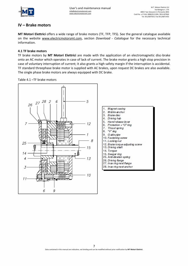
4.1 TF brake motors
TF brake motors by MT Motori Elettrici are made with the application of an electromagnetic disc-brake
onto an AC motor which operates in case of lack of current. The brake motor grants a high stop precision in
case of voluntary interruption of current; it also grants a high safety margin if the interruption is accidental.
TF standard threephase brake motor is supplied with AC brakes, upon request DC brakes are also available.
The single phase brake motors are always equipped with DC brake.
Table 4.1 –TF brake motors
User's and maintenance manual [email protected]
www.electricmotorsmt.com
M.T. Motori Elettrici Srl
Via Bologna n. 175
40017 San Giovanni in Persiceto (BO)
Cod.Fisc. e P.IVA: 00863511200 / REA 407664
Tel. 051/6875011 Fax 051/6871455
8 Data contained in this manual are indicative, not binding and can be modified without prior notification by MT Motori Elettrici.
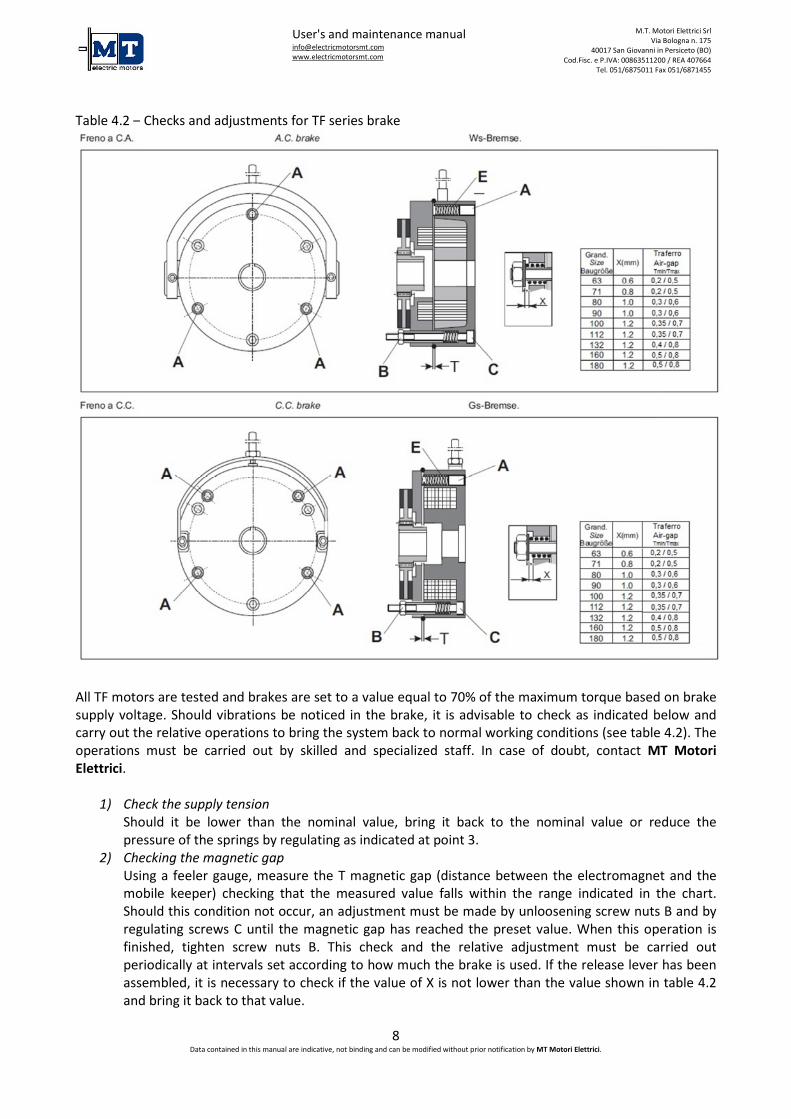
Table 4.2 – Checks and adjustments for TF series brake
All TF motors are tested and brakes are set to a value equal to 70% of the maximum torque based on brake
supply voltage. Should vibrations be noticed in the brake, it is advisable to check as indicated below and
carry out the relative operations to bring the system back to normal working conditions (see table 4.2). The
operations must be carried out by skilled and specialized staff. In case of doubt, contact MT Motori
Elettrici.
1) Check the supply tension
Should it be lower than the nominal value, bring it back to the nominal value or reduce the
pressure of the springs by regulating as indicated at point 3.
2) Checking the magnetic gap
Using a feeler gauge, measure the T magnetic gap (distance between the electromagnet and the
mobile keeper) checking that the measured value falls within the range indicated in the chart.
Should this condition not occur, an adjustment must be made by unloosening screw nuts B and by
regulating screws C until the magnetic gap has reached the preset value. When this operation is
finished, tighten screw nuts B. This check and the relative adjustment must be carried out
periodically at intervals set according to how much the brake is used. If the release lever has been
assembled, it is necessary to check if the value of X is not lower than the value shown in table 4.2
and bring it back to that value.

User's and maintenance manual [email protected]
www.electricmotorsmt.com
M.T. Motori Elettrici Srl
Via Bologna n. 175
40017 San Giovanni in Persiceto (BO)
Cod.Fisc. e P.IVA: 00863511200 / REA 407664
Tel. 051/6875011 Fax 051/6871455
9 Data contained in this manual are indicative, not binding and can be modified without prior notification by MT Motori Elettrici.
3) Adjusting the braking torque
The braking torque is proportional to the compression of springs E and it is possible to change it by
regulating the dowels A (3 for the motor sizes 63-112, 5 for the motor sizes 132-180) in sequence
and in a uniform manner; on this matter, it is advisable to rotate each screw by 1/2 turn and retry
the brake functioning.
Tab. 4.3 – Checking the braking torque of TF range
The braking torque can be adjusted by means of the adjusting screws (12,
table 4.1) situated at the back of the brake. When loosening the screws
completely, the braking torque will not go under the 35% safety value. When
tightening the screws to the level of the back surface, the braking torque
adjustment will be 50%. For other adjustments, refer to the diagram.
Maintenance
Overhaul and repair operations can only be carried out by skilled and specialized staff. In case of doubt,
contact MT Motori Elettrici. The periodical maintenance interval should be determined according to the
load to be braked and relative braking work; breaking work that can be carried out by the brake between
two adjustment intervals. During maintenance check that the friction packing minimum thickness is not
lower than 1 mm; check that the play between brake disk (3, table 4.1) and driving hub (4, table 4.1) is not
excessive; check the absence of play between the tongue (14, table 4.1) and its housing on the hub; check
the absence of play between driving hub (4, table 4.1) and driving shaft (13, table 4.1); replace worn parts;
adjust the air gap taking it back to its initial value, by means of the screws (10, table 4.1) and lock it with
the nuts (11, table 4.1).
4.2 TFP brake motors
The motors of TFP range are equipped with electromagnetic springs brake, they work with a.c. and the disk
brake has double braking surface.
Tab. 4.4 –TFP brake motors
Traferro / Air Gap
Taglia /
Size Tmin Tmax
63 0,30 0,70
71 0,30 0,70
80 0,30 0,70
90 0,30 0,70
100 0,30 0,70
112 0,40 0,80
132 0,40 0,80
160 0,5 1
180 0,5 1
200 0,65 1,15

User's and maintenance manual [email protected]
www.electricmotorsmt.com
M.T. Motori Elettrici Srl
Via Bologna n. 175
40017 San Giovanni in Persiceto (BO)
Cod.Fisc. e P.IVA: 00863511200 / REA 407664
Tel. 051/6875011 Fax 051/6871455
10 Data contained in this manual are indicative, not binding and can be modified without prior notification by MT Motori Elettrici.
All TFP motors are provided with the screw for the brake hand release. Therefore it is possible to manually
rotate the output shaft with a full shaft hexagonal key of 5 mm, for the 63 – 100 sizes, and of 6 mm, for the
112 – 200 sizes. TFP motors are tested and brakes are set to a value equal to 70% of the maximum torque
based on brake supply voltage. Should vibrations be noticed in the brake, it is advisable to check as
indicated below and carry out the relative operations to bring the system back to normal working
conditions (see table 4.4). The operations must be carried out by skilled and specialized staff. In case of
doubt, contact MT Motori Elettrici.
1) Check the supply tension
Should it be lower than the nominal value, bring it back to the nominal value or reduce the
pressure of the springs by regulating as indicated at point 3.
2) Checking the magnetic gap
Using a feeler gauge, measure the T magnetic gap (distance between the electromagnet and the
mobile keeper) checking that the measured value falls within the range indicated in the chart 4.4.
Should this condition not occur, an adjustment must be made by unloosening nuts (see table 4.4 -
detail 22) until the magnetic gap has reached the preset value. When this operation is finished,
tighten the nuts. This check and the relative adjustment must be carried out periodically at
intervals set according to how much the brake is used.
3) Adjusting the braking torque
The braking torque is proportional to the compression of springs and it is possible to change it by
regulating the dowels which compressing the spring (see table 4.4 – detail 23). It is advisable to
rotate each dowel by 1/2 turn and retry the brake functioning.
Maintenance
Overhaul and repair operations can only be carried out by skilled and specialized staff. In case of doubt,
contact MT Motori Elettrici. The periodical maintenance interval should be determined according to the
load to be braked and relative braking work; breaking work that can be carried out by the brake between
two adjustment intervals. During maintenance check that the friction packing minimum thickness is not
lower than 1 mm; check that the play between brake disk (3, table 4.4) and driving hub (4, table 4.4) is not
excessive; check the absence of play between the tongue (14, table 4.4) and its housing on the hub; check
the absence of play between driving hub (4, table 4.4) and driving shaft (13, table 4.4); replace worn parts;
adjust the air gap taking it back to its initial value, by means of the nuts (22, table 4.4).
4. TFS brake motors
The motors of TFS range are equipped with an electromagnetic standing brake, a d.c. coil and fixed braking
torque. The brake feeding is directly connected to the motor terminal board by a rectifier. Upon request it
is possible to supply separate feeded brakes. With two speed motors or motors working through inverters
it is advisable to adopt brakes with separate feeding.

User's and maintenance manual [email protected]
www.electricmotorsmt.com
M.T. Motori Elettrici Srl
Via Bologna n. 175
40017 San Giovanni in Persiceto (BO)
Cod.Fisc. e P.IVA: 00863511200 / REA 407664
Tel. 051/6875011 Fax 051/6871455
11 Data contained in this manual are indicative, not binding and can be modified without prior notification by MT Motori Elettrici.
Tab. 4.5 – TFS brake motors
Traferro / Air Gap
Taglia /
Size Tmin Tmax
63 0,20 0,5
71 0,20 0,6
80 0,20 0,6
90 0,20 0,6
100 0,25 0,6
112 0,25 0,6
132 0,25 0,7
160 0,25 0,7
Maintenance
Overhaul and repair operations can only be carried out by skilled and specialized staff. In case of doubt,
contact MT Motori Elettrici. The periodical maintenance interval should be determined according to the
load to be braked and relative braking work; breaking work that can be carried out by the brake between
two adjustment intervals. During maintenance check that the friction packing minimum thickness is not
lower than 1 mm; check that the play between fan hole (17, table 4.5) and driving shaft (13, table 4.5) is not
excessive; check the absence of play between the tongue (14, table 4.5) and its housing on the hub; adjust
the air gap taking it back to its initial value (table 4.5), by means of the self-locking nut (19, table 4.5);
replace worn parts.
4.4 Brake wiring diagram
MT Motori Elettrici supplies TF, TFP and TFS brake motors in AC or DC directly feeded from the terminal
board, prepared for separate feeding. Upon request it is possible to supply TF, TFP and TFS brake motors in
AC or DC with separate feeding (this solution is advisable in case of two speed motors and motors operated
through inverters).
Table 4.6 - Wiring diagram AC Brake (TF and TFP)
U1 – Black
V1 – Red
W1 – Brown
W2 – Brown-White
U2 – Black- White
V2 – Red- White

User's and maintenance manual [email protected]
www.electricmotorsmt.com
M.T. Motori Elettrici Srl
Via Bologna n. 175
40017 San Giovanni in Persiceto (BO)
Cod.Fisc. e P.IVA: 00863511200 / REA 407664
Tel. 051/6875011 Fax 051/6871455
12 Data contained in this manual are indicative, not binding and can be modified without prior notification by MT Motori Elettrici.
DC brake
Brake motors with DC brake are supplied with the following rectifiers.
• NBR500-1 (sizes 56-90) • SBR440-1 (sizes 100-200)
Upon request different rectifiers can be provided.
Table 4.7 – Wiring diagram DC Brake (TF, TFP and TFS)
1-2: AC inlet
3-4: contact for fast braking
5-6: DC outlet
7-8-9: auxiliary terminals

User's and maintenance manual [email protected]
www.electricmotorsmt.com
M.T. Motori Elettrici Srl
Via Bologna n. 175
40017 San Giovanni in Persiceto (BO)
Cod.Fisc. e P.IVA: 00863511200 / REA 407664
Tel. 051/6875011 Fax 051/6871455
13 Data contained in this manual are indicative, not binding and can be modified without prior notification by MT Motori Elettrici.
V – ATEX and UL certificates
MT Motori Elettrici supplies a wide range of motors with ATEX certificate, in compliance with the
2014/34/UE European directive. In particular, MT Motori Elettrici motors can be used in hazardous areas
and explosive atmospheres. Standard supply is certified ATEX for the following series TN, DN, MN, XN, TF,
DF, MF, XF, TFP, DFP, sizes 56-200. Aforementioned motors can be installed in following conditions: group
II, category 3G-3D, zones 2-22. The codes identifying these products, also provided on the plate, are as
follows:
II 3G Ex nA IIC T4/T3 Gc
II 3D Ex tc IIIC T135°/T200°C Dc
MT Motori Elettrici also provides a wide range of motors to be used in hazardous areas and explosive
atmospheres, under following codes:
II 2G Ex e II T4/T3 Gb
II 2D Ex tb IIIC T135°/T200°C Db
Aforementioned motors, known as high safety electric motors, can be installed in following conditions:
group II, category 2G-2D, zones 1-21.
For further information visit the website www.electricmotorsmt.com, section Download - Operating
Instructions and User's Manual. Always comply with instructions contained in the manuals and with the
regulations on the use of the devices in hazardous areas. Motors must be moved, installed, operated and
maintained only by skilled staff knowing all of the regulations on explosion protection.
MT Motori Elettrici motors are also certified UL-CSA, with certificate UL 1004 CSA C22.2 Nr. 100-95.
Documents on different ATEX certificates and on the UL-CSA certificate are available on the website
www.electricmotorsmt.com, section Download - Certificates.
For further clarification, contact MT Motori Elettrici.

User's and maintenance manual [email protected]
www.electricmotorsmt.com
M.T. Motori Elettrici Srl
Via Bologna n. 175
40017 San Giovanni in Persiceto (BO)
Cod.Fisc. e P.IVA: 00863511200 / REA 407664
Tel. 051/6875011 Fax 051/6871455
14 Data contained in this manual are indicative, not binding and can be modified without prior notification by MT Motori Elettrici.
VI – Inverter use
MT Motori Elettrici motors are suitable for operating with inverters. Further information on motors used
with inverter can be found in following chart.
V230/400-50Hz motors with V400-50Hz inverter are available in two possible operating types:
A) Y-connected motor, constant V/f ratio up to 50Hz;
P ≈ PN; I ≈ IN;
5 ÷ 35 Hz = self-ventilated motor is slightly cooled, so M decreases by decreasing f. M keeps
constant in motors with servo ventilation (servo ventilation under 40Hz);
÷ 50 Hz = motor operates at constant M (= MN);
> 50 Hz = motor operates at constant P ≈ PN with decreased V/f ratio with reference to nominal
value (V keeps unvaried, f increases) with following M decrease at the same current-absorption
level.
(V400/690-50Hz motors can only have this operating type and must be ∆-connected).
B) ∆-connected motor, constant V/f ratio up to 87 Hz;
PMAX ≈ 1.73 PN; I ≈ 1.73 IN 400V ≈ IN 230V;
5 ÷ 35 Hz = self-ventilated motor is slightly cooled, so M decreases by decreasing f M keeps
constant (≈ MN) in motors with servo ventilation (servo ventilation under 40Hz);
35 ÷ 87 Hz = motor operates at constant M (≈ MN);

User's and maintenance manual [email protected]
www.electricmotorsmt.com
M.T. Motori Elettrici Srl
Via Bologna n. 175
40017 San Giovanni in Persiceto (BO)
Cod.Fisc. e P.IVA: 00863511200 / REA 407664
Tel. 051/6875011 Fax 051/6871455
15 Data contained in this manual are indicative, not binding and can be modified without prior notification by MT Motori Elettrici.
> 87 Hz = motor operates at constant P (≈ 1.73 PN) with progressively decreased V/f ratio with
reference to nominal value (V keeps unvaried, f increases) with following M decrease at the same
current-absorption level.
Inverter use must be combined with the use of thermistors. In case of frequencies lower than 40Hz it is
necessary to provide the motor with servo ventilation. Further information can be found in the MT Motori
Elettrici general catalogue. For particular applications and further specifications see the ATEX manual.
Should clarifications be necessary, contact MT Motori Elettrici.
Related Documents


