Access Easy Controller 2.1 APC-AEC21-UPS1 en Software Manual

Welcome message from author
This document is posted to help you gain knowledge. Please leave a comment to let me know what you think about it! Share it to your friends and learn new things together.
Transcript

7/18/2019 User_Guide___Instruction_Book_enUS_1385855115.pdf
http://slidepdf.com/reader/full/userguideinstructionbookenus1385855115pdf 1/194
Access Easy Controller 2.1APC-AEC21-UPS1
en Software Manual

7/18/2019 User_Guide___Instruction_Book_enUS_1385855115.pdf
http://slidepdf.com/reader/full/userguideinstructionbookenus1385855115pdf 2/194

7/18/2019 User_Guide___Instruction_Book_enUS_1385855115.pdf
http://slidepdf.com/reader/full/userguideinstructionbookenus1385855115pdf 3/194
Access Easy Controller 2.1 Table of Contents | en 3
Bosch Security Systems Software Manual F.01U.122.797 | 1.0.4 | 2010.10
Table of Contents
1 Introduction 9
1.1 Access Easy Controller 2.1 Functional Features 9
1.2 Powering up Access Easy Controller 2.1 11
2 Overview of Access Easy Controller 2.1 13
3 Accessing Access Easy Controller 2.1 15
3.1 Connecting to Access Easy Controller 2.1 15
3.2 System Requirements 15
3.3 Accessing Access Easy Controller 2.1 Software 15
3.4 Logging into Access Easy Controller 2.1 16
3.4.1 Logging in Access Easy Controller 2.1 17
3.4.2 Logging off from Access Easy Controller 2.1 17
4 Installing ActiveX and VideoSDK 18
4.1 Installation Procedure for Video SDK 18
5 Main Menu Groups 20
5.1 Menu Description 20
5.1.1 Activity 20
5.1.2 Card 21
5.1.3 Configuration 21
5.1.4 System 21
5.1.5 Report 225.1.6 Logout 22
5.2 Navigating Through Access Easy Controller 2.1 page 22
5.3 Usage of the buttons 22
6 Activity 25
6.1 Transactions 25
6.1.1 All 27
6.1.2 Alarm 28
6.1.3 Valid & Alarm 29
6.1.4 Restore & Alarm 29
6.1.5 Time Attendance 29
6.1.6 APB 29
6.1.7 Video Verification 30
6.1.8 Online Swipe 31
6.1.9 Surveillance 34
6.1.10 Camera Monitoring 37
6.2 Device Control 39
6.2.1 Door Control 39
6.2.2 Input Control 41
6.2.3 Output Control 43
6.3 Activity - Default Settings 45

7/18/2019 User_Guide___Instruction_Book_enUS_1385855115.pdf
http://slidepdf.com/reader/full/userguideinstructionbookenus1385855115pdf 4/194
4 en | Table of Contents Access Easy Controller 2.1
F.01U.122.797 | 1.0.4 | 2010.10 Software Manual Bosch Security Systems
6.3.1 To edit Transactions Setting 45
7 Card Administration 46
7.1 Card Assignment 46
7.1.1 Card Details 48
7.1.2 Card Functionality 507.1.3 The Search Function 55
7.2 Card Enrollment 57
7.2.1 Card Enrollment Using Web Page 57
7.3 Import/Export Function 58
7.3.1 Exporting the Card Database 59
7.3.2 Importing the Card Database 60
7.4 Batch Cards 60
7.4.1 Adding Batch Cards 60
7.4.2 To delete a Batch of Card Number 61
7.4.3 To add a Batch of Card Number with same data entries 61
7.4.4 System Messages 62
8 Card Fields Configuration 64
8.1 Access Groups 64
8.1.1 To configure/edit Access Group parameters 64
8.2 Card Format 65
8.3 Department 68
8.4 Reset APB 69
8.5 Card - Default Settings 70
8.5.1 To edit the User Definable Fields and Facility Code 70
9 Door Settings (Card Reader Settings) 71
9.1 To Setup the card readers 71
9.2 Reader Function 73
9.2.1 Reader Options 74
9.2.2 Scheduling Options 77
9.3 IO Configuration 78
9.3.1 Door Output Settings (For Entry Reader, Entry and Arm/Disarm Reader) 78
9.3.2 Door Input Settings (For Entry Reader, Entry and Arm/Disarm Reader) 79
9.3.3 Floor Output Settings (For Elevator Reader Only) 81
9.3.4 Output Link 81
9.4 Advanced 829.4.1 PIN Code Settings 82
9.4.2 Anti-Passback (APB) Settings 83
9.4.3 Dual Card Configuration 85
9.5 Video Setup 86
9.5.1 Verification Camera Setting 87
9.5.2 Surveillance Camera setting 88
9.5.3 Optional Camera Setting 88
10 Videos 90
10.1 Installing DirectX and Video SDK 90

7/18/2019 User_Guide___Instruction_Book_enUS_1385855115.pdf
http://slidepdf.com/reader/full/userguideinstructionbookenus1385855115pdf 5/194
Access Easy Controller 2.1 Table of Contents | en 5
Bosch Security Systems Software Manual F.01U.122.797 | 1.0.4 | 2010.10
10.1.1 Installing Video SDK 90
10.2 Web Browser settings for accessing Video features in AEC2.1 90
10.3 Video Configuration 93
10.3.1 Device Type addition 93
10.3.2 Adding camera to AEC2.1 94
10.3.3 Miscellaneous 99
11 Input/Output Setup 100
11.1 Input Setup 100
11.1.1 To activate the Input Setup 101
11.2 Output Setup 104
11.2.1 To activate the Output Setup 105
11.2.2 Disable Activity From Output Point 107
12 Advance IO Setup 109
12.1 Guard Tour 109
12.2 Feed Through 110
12.3 OR Logic 111
12.4 AND Logic 111
12.5 XOR Logic 112
12.6 NAND Logic 113
12.7 Interlock / Man Trap 114
12.8 Up-Down Counter 119
12.9 Exit Door 120
12.10 One Shot 122
12.11 Intrusion Function 122
13 Input State 124
13.1 Input Point Configuration 124
13.1.1 To activate Input Point Configuration 124
13.1.2 To select Input Point Configuration 124
13.2 Alarm Zone Description 125
14 Criteria 126
14.1 Configuration Setting 126
14.2 Cardholder Setting 128
14.3 Event Setting 132
14.4 Time Setting 133
15 Schedules and Holidays 134
15.1 Schedules 134
15.1.1 System Behavior when using Schedule 136
15.2 Holidays 137
16 Users 139
16.1 User Administration 139
16.1.1 To enter user information 139

7/18/2019 User_Guide___Instruction_Book_enUS_1385855115.pdf
http://slidepdf.com/reader/full/userguideinstructionbookenus1385855115pdf 6/194
6 en | Table of Contents Access Easy Controller 2.1
F.01U.122.797 | 1.0.4 | 2010.10 Software Manual Bosch Security Systems
16.1.2 To select user profile 140
17 Network Settings 143
17.1 Network 143
17.1.1 Network Setting 143
17.1.2 Remote PC Addresses 14417.2 Email Server Setup Information 144
17.2.1 To Configure the Email Server Setup Information 145
17.3 Dial In IP Setup Information 145
17.3.1 To edit the Dial In IP Settings Information 145
17.4 SMS Server Settings Information 146
17.4.1 To Configure Access Easy Controller 2.1 as a SMS Server 146
17.5 AEMC Settings 147
17.6 LAN Converter 148
18 System Settings 149
18.1 Date and Time 149
18.1.1 Set Date & Time 149
18.1.2 To activate Date & Time Setting 149
18.1.3 To set the Date & Time 149
18.2 NTP Settings (Network Time Protocol Settings) 150
18.2.1 To set the Time Synchronization 150
19 Email/SMS Configuration 152
19.1 Email Configuration 152
19.1.1 To edit the Email Configuration 152
19.1.2 To send the Email 15319.2 SMS Configuration 153
19.2.1 To send the Email 154
19.3 Message Configuration 154
19.3.1 To edit the Message field 154
20 Advance Settings 155
20.1 System Maintenance 155
20.1.1 To activate Reboot Panel 155
20.1.2 To Shutdown Panel 155
20.2 Firmware Upgrade 156
20.2.1 To Upload Settings and Configurations on the Panel 156
20.2.2 To Update Panel Software 157
20.3 Database Backup 157
20.3.1 To activate Database Backup 158
20.3.2 To define Daily Backup Schedule 158
20.3.3 To Backup System Database To Desktop 158
20.4 Customer Logo 159
20.5 Video SDK 159
20.5.1 Upload Video SDK 160
20.6 System - Default Settings 161
20.6.1 Auto Logout Timer 161

7/18/2019 User_Guide___Instruction_Book_enUS_1385855115.pdf
http://slidepdf.com/reader/full/userguideinstructionbookenus1385855115pdf 7/194
Access Easy Controller 2.1 Table of Contents | en 7
Bosch Security Systems Software Manual F.01U.122.797 | 1.0.4 | 2010.10
20.6.2 PIN Settings 161
21 Reports 163
21.1 Activity 163
21.1.1 To format report based on Card Number 164
21.1.2 To format report based on Name 16421.1.3 To format report based on Department 164
21.1.4 To format report based on Location 165
21.1.5 To format report based on Date/Time 165
21.2 APB 165
21.2.1 To generate APB Zones Report 165
21.3 Card 166
21.4 Access Group 167
21.4.1 To generate an Access Groups report 167
21.5 Reader 167
21.5.1 To generate a Card Reader Report 167
21.6 Input 16721.6.1 To generate an Input Point Report 167
21.7 Output 168
21.7.1 To generate an Output Point Report 168
21.8 Advance I/O 168
21.8.1 To generate an I/O function Block Report 168
21.9 Camera 169
21.9.1 To generate a Report based on Camera 169
21.10 Schedule 169
21.10.1 To generate a Schedule Report 169
21.11 Regular Holiday 169
21.11.1 To generate a Regular Holiday Report 17021.12 Special Holiday 170
21.12.1 To generate a Special Holiday Report 170
21.13 Audit Log 170
21.14 View .CSV file in Excel 171
21.15 Report - Default Settings 172
21.15.1 To edit the report settings 173
22 Resetting to Factory Default 174
22.1 Resetting IP Address to Default IP Address 175
23 APPENDIX A 176
23.1 Initial Setup To Access Easy Controller 2.1 176
23.2 Configuring a Web Browser to Work with Access Easy Controller 2.1 177
23.3 Install AEC2.1 certificate on a Windows Computer 181
24 APPENDIX B 186
24.1 Procedure to set the IP Address of computer 186
25 APPENDIX C 190
25.1 Activity Transactions 190

7/18/2019 User_Guide___Instruction_Book_enUS_1385855115.pdf
http://slidepdf.com/reader/full/userguideinstructionbookenus1385855115pdf 8/194
8 en | Table of Contents Access Easy Controller 2.1
F.01U.122.797 | 1.0.4 | 2010.10 Software Manual Bosch Security Systems
25.2 Alarm Activity 190
25.3 Restore Activity 190
25.4 Valid Activity 190
25.5 Time Attendance 191
26 Troubleshooting 192

7/18/2019 User_Guide___Instruction_Book_enUS_1385855115.pdf
http://slidepdf.com/reader/full/userguideinstructionbookenus1385855115pdf 9/194
Access Easy Controller 2.1 Introduction | en 9
Bosch Security Systems Software Manual F.01U.122.797 | 1.0.4 | 2010.10
1 IntroductionAccess Easy Controller 2.1 (AEC2.1) is a new generation IP web based security system that
allows you to control and monitor access routes with flexibility and conveniences to suit
individual needs.
Access Easy Controller 2.1 uniquely combines the features of a Web server, video integrationand security system in one complete unit. Such powerful combination provides a highly cost-
effective solution, which provides simplicity and ease-of-use associated with the popular Web
interface while incorporating a rich suite of sophisticated security features essential for all
businesses.
The design of Access Easy Controller 2.1 adopts the common desktop metaphor for all web
based applications for consistency and ease of use.
Access Easy Controller 2.1 provides the necessary operation of an Access Control system and
comes with its own Intrusion Detection system. The Access Easy Controller 2.1 can store up
to 20,480 Card IDs in it’s database and hold up to 100,000 transactions/events. Features suchas video integration, video verification, Email and Short text Messaging Service (SMS) are
available in Access Easy Controller 2.1.
This software manual helps you understand the software interface and the different menu
features available in Access Easy Controller 2.1.
1.1 Access Easy Controller 2.1 Functional Features
Access Easy Controller 2.1 Functional Features
Item Description Remarks
1 Door access control X
2 Intrusion alarm/input monitoring X
3 Output device control (on/off) X
4 Time attendance clocking X
5 Email messaging upon triggered events X
6 SMS messaging upon triggered events X
7 View Live and Playback videos X
8 Video verification for door access X
9 Search event videos for verification X
10 Modem dial-in from remote PC X
11 Backup database (parameters, activities & audit log) into
compact flash
X
12 Integrate to Access Easy Master Controller X

7/18/2019 User_Guide___Instruction_Book_enUS_1385855115.pdf
http://slidepdf.com/reader/full/userguideinstructionbookenus1385855115pdf 10/194
10 en | Introduction Access Easy Controller 2.1
F.01U.122.797 | 1.0.4 | 2010.10 Software Manual Bosch Security Systems
13 Priority anti-passback zone (254 zones) operation and only
registered if door contact detect door being open by
cardholder
X
14 Door forced open alarm delay X
15 Door held open pre-warning X
16 Reader lockout after a pre-define invalid card event X
17 Elevator access control X
18 Integrated door access reader with arm/disarm function
(using same reader)
X
19 Special cardholder with extended duration for door strike and
keypad
X
20 One time access X
21 Dual card entry (2 man rule) X
22 Card enrollment function for any card with unknown card
format
X
23 Option to unlock door by schedule only after a valid access
card is presented
X
24 Input monitoring (door contact, request-to-exit, alarm input
points) supports configurable 2 state non-supervise, 2 state
supervise and 4 state supervise for all input points in the
controller.
Configurable:- 2
state nonsupervise
(no EOL), 2 state
supervise (6.8K
EOL), 4 state
supervise (12K &
15K EOL)
25 Card database import and export function (in CSV format) X
26 Real time activities and status update X
27 Department field in the card assignment 30 alpha-numeric
characters
28 Advance IO (guard tour, feed through, OR, AND, XOR, NAND,
up/down counter, exit door, one shot and intrusion)
X
29 Support interlock/mantrap operation using advance IO
configuration.
X
30 Browser login encryption 128 bits SSL
Access Easy Controller 2.1 Functional Features
Item Description Remarks

7/18/2019 User_Guide___Instruction_Book_enUS_1385855115.pdf
http://slidepdf.com/reader/full/userguideinstructionbookenus1385855115pdf 11/194
Access Easy Controller 2.1 Introduction | en 11
Bosch Security Systems Software Manual F.01U.122.797 | 1.0.4 | 2010.10
1.2 Powering up Access Easy Controller 2.1
Access Easy Controller 2.1 is incorporated with some beep sounds in the system for you to
identify the stages/faults in the system/events etc. The table below lists the beep sounds that
you may encounter while booting the system.
Maximum Capacities
Item Description Capacity
1 Wiegand reader support 32
2 Input monitoring points 64
3 Relay outputs 64
4 Cardholder 20480
5 Transaction history 100,000
6 Audit log 1023
7 Compact flash size 512 MB
8 Video camera to a reader or input/output point or advance IO
function block
3
Types of Beep during Boot up Significance/Stages in Booting Sequence
2 short beeps When the panel is powered up, a boot up check will be
carried out. The CPU will authenticate with its security
key before proceeding to run the software
Continuous beep for 60 seconds Occurs after boot up check and if verification of the
security key fails.
3 short beeps Occurs when the system starts to launch the back end
program.
Continuous beep for 30 seconds Occurs when any decrypting failure takes place.
5 beeps in ascending tune Occurs when all the back end programs are launched
successfully.
8 beeps Occurs when the boot up is complete.
Types of Beep when Software is
Running
Significance
2 short beeps Faults occur in Webacu file.
3 short beeps Faults occur in Webcru file.
4 short beeps Faults occur in Webser file.

7/18/2019 User_Guide___Instruction_Book_enUS_1385855115.pdf
http://slidepdf.com/reader/full/userguideinstructionbookenus1385855115pdf 12/194
12 en | Introduction Access Easy Controller 2.1
F.01U.122.797 | 1.0.4 | 2010.10 Software Manual Bosch Security Systems
NOTICE!
The software errors are auto fixed in the program.

7/18/2019 User_Guide___Instruction_Book_enUS_1385855115.pdf
http://slidepdf.com/reader/full/userguideinstructionbookenus1385855115pdf 13/194
Access Easy Controller 2.1 Overview of Access Easy Controller 2.1 | en 13
Bosch Security Systems Software Manual F.01U.122.797 | 1.0.4 | 2010.10
2 Overview of Access Easy Controller 2.1
The basic AEC2.1 system consists of a single metal enclosure with three components: CPU, 4-
Reader board, and Power Supply Unit (PSU). Space is provided for a 12-volt standby battery
to sustain the system in event of a power failure. The PSU in the controller has an input power
of 100~240 VAC.
The enclosure is key locked and is equipped with a tamper switch to detect any tampering of
the panel, and/or when the controller door is being opened.
Figure 2.1 AEC2.1 Main Enclosure
In its minimum configuration, an AEC2.1 system supports one 4-Reader board. The boardcomes with, 4 card reader, 8 input, and 8 output ports to support all necessary hardware
(door lock/strike outputs, door contact inputs and request-to-exit inputs). A full AEC2.1
system supports up to a maximum of 16 interface boards (eight 4-Reader boards and eight 8-
IO boards). This allows the AEC2.1 system to support up to 32 card readers, 64 alarm type
input and 64 controllable output points.
CPU Board - The CPU board contains a microprocessor, RAM memory and all necessary
electronic circuitry to interact with other circuit boards. The CPU board contains the
hardware and software needed to interface to an Ethernet-type network and to communicate
with host computers using TCP/IP protocol.
4-Reader Board - The 4-Reader board is an interface board for AEC2.1. The reader board
contains all circuitry necessary to interface with, and operate, up to four card readers. The
reader board also provides wiring termination points for the readers, door strikes or magnetic
locks, door contacts and request-to-exit devices. The first interface board of the system
communicates with the CPU board via the RS232 channel. The subsequent interface boards
are linked through a multi-drop communication channel, RS485, to form the system. The PSU
supplies the required 12V DC power to the board.
8-Input-Output Board -The 8-IO board is an interface board for AEC2.1.The 8-IO board
provides the necessary circuitry to monitor 8-alarm type (non-reader) inputs, and to control

7/18/2019 User_Guide___Instruction_Book_enUS_1385855115.pdf
http://slidepdf.com/reader/full/userguideinstructionbookenus1385855115pdf 14/194
14 en | Overview of Access Easy Controller 2.1 Access Easy Controller 2.1
F.01U.122.797 | 1.0.4 | 2010.10 Software Manual Bosch Security Systems
up to eight external devices, such as bells, fans, lights, etc. The board also provides wiring
termination points for the input and output devices. The first interface board of the system
communicates with the CPU board via the RS232 channel. The subsequent interface boards
are linked up through a multi-drop communication channel, RS485. The PSU supplies the
required 12V DC power to the board.
Access Easy Extension - Access Easy Extension is a metal enclosure identical in size to the
basic AEC2.1. The Extension unit contains a Power Supply Unit, and space to install up to two
additional 4-Reader boards and/or 8-IO boards. Space is provided for an optional 12V, 7AH
standby battery to sustain the system in time of power failure.
NOTICE!
AEC2.1 does not come with the 12V DC standby battery.

7/18/2019 User_Guide___Instruction_Book_enUS_1385855115.pdf
http://slidepdf.com/reader/full/userguideinstructionbookenus1385855115pdf 15/194
Access Easy Controller 2.1 Accessing Access Easy Controller 2.1 | en 15
Bosch Security Systems Software Manual F.01U.122.797 | 1.0.4 | 2010.10
3 Accessing Access Easy Controller 2.1
This chapter explains the basic information on how to access the AEC2.1 and log onto the
software.
A standard web browser program such as Internet Explorer 7.0 and later is required to accessor monitor the AEC2.1.
3.1 Connecting to Access Easy Controller 2.1
Before accessing the AEC2.1, it must be configured and integrated to the existing computer
network.
As this integration requires knowledge on networking, it is the responsibility of the System
Installer to work closely with your company's Network Administrator to do the initial set up.
However, for general knowledge, a description is presented in Appendix A. Refer to
Section 23 APPENDIX A, page 176 for more information. For users accessing the AEC2.1 using
their own computer, refer to the section ‘Setting to be made to the Web Browser’.
3.2 System Requirements
Check the following minimum hardware and software requirements on the Remote PC to
access the AEC2.1.
– 10/100Base-T Ethernet card
– CD drive– Operating System (Windows)
– Windows XP/Vista
– .NET Framework 3.0
– Standard Web browser (Internet Explorer version 7 and later)
– DirectX 9.0cVideo card that supports DirectX 9.0c (For video features only)
The AEC2.1 can be accessed after all the preceding system requirements are met.
Note: Video integration features are available on Windows XP/Vista OS only.
3.3 Accessing Access Easy Controller 2.1 Software
A working knowledge of Windows and Internet Explorer is required to access the AEC2.1.
To get connected to AEC2.1, launch the web browser program (Internet Explorer 7.0 and
later) and key in the AEC2.1's URL address followed by the Enter key. The factory default URL
for AEC2.1 is 192.168.0.41.
The screen below shows an example of the web browser with the default URL address for the
AEC2.1.

7/18/2019 User_Guide___Instruction_Book_enUS_1385855115.pdf
http://slidepdf.com/reader/full/userguideinstructionbookenus1385855115pdf 16/194
16 en | Accessing Access Easy Controller 2.1 Access Easy Controller 2.1
F.01U.122.797 | 1.0.4 | 2010.10 Software Manual Bosch Security Systems
Figure 3.1 AEC2.1 Default URL address
Note: All screens are presented in Internet Explorer 7.0.
This will bring up the login page.
3.4 Logging into Access Easy Controller 2.1
The login screen appears as shown below.
This User Login dialog box provides a security control that protects the AEC2.1 from
unauthorized access. Enter your user id and password in the User Name and Password field
to gain access to the AEC2.1. Select the required GUI language from the language dropdown.
The system allows upto 8 users to logon the same AEC2.1 using different computers.
When the AEC2.1 is first installed, there is only one assigned user ID and password. This
default user ID is called the Super-user and is usually assigned to the AEC2.1 System
Administrator. The Super-user has the full access rights to all features of the AEC2.1,
including the AEC2.1 Utility programs. The user id and password of the Super-user id can be
changed but the access rights cannot be changed.
The default IP Address - 192.168.0.41, User ID = user1 and Password = 8088
NOTICE!
The User ID and Password are case-sensitive and can be changed.

7/18/2019 User_Guide___Instruction_Book_enUS_1385855115.pdf
http://slidepdf.com/reader/full/userguideinstructionbookenus1385855115pdf 17/194
Access Easy Controller 2.1 Accessing Access Easy Controller 2.1 | en 17
Bosch Security Systems Software Manual F.01U.122.797 | 1.0.4 | 2010.10
3.4.1 Logging in Access Easy Controller 2.1
1. Enter your assigned User ID in the User Name field.
2. Enter your assigned Password in the Password field.
3. Select the required GUI language from the Language dropdown.
4. Click the login button to log into AEC2.1.
If you do not know your User ID and Password, contact your AEC2.1 system administrator to
obtain them. User IDs and Passwords are configured by the AEC2.1 system administrator.
3.4.2 Logging off from Access Easy Controller 2.1
After you finish your session with AEC2.1 or need to be away from the computer, it is
recommended to log off from the AEC2.1.
To log off, click the logout link on the top of the page.
NOTICE!
Once the system is commissioned and handed-over, change the default User ID and
Passwordas soon as possible to prevent unauthorized access.
NOTICE!
Changing the language in the login page changes the GUI language interface and not the data
in the database.
NOTICE!
ALWAYS LOG OFF BEFORE LEAVING THE COMPUTER!

7/18/2019 User_Guide___Instruction_Book_enUS_1385855115.pdf
http://slidepdf.com/reader/full/userguideinstructionbookenus1385855115pdf 18/194
18 en | Installing ActiveX and VideoSDK Access Easy Controller 2.1
F.01U.122.797 | 1.0.4 | 2010.10 Software Manual Bosch Security Systems
4 Installing ActiveX and VideoSDK
Install ActiveX and VideoSDK to access the video features of AEC2.1.
The ActiveX and Video SDK is installed automatically when the AEC2.1 system is set. If the
Video SDK is not installed automatically then you can install it from the utility CD or retrievethe files from the VideoSDK page. Refer to Section 20.5 Video SDK, page 159 in Advance
settings for more information.
Refer to the section below for installing VideoSDK from the utility CD.
4.1 Installation Procedure for Video SDK
The steps below will guide you through the installation of the Video SDK.
1. Place the CD in the CD-ROM and open the folder BOSCH VideoSDK. In the BOSCH
VideoSDK folder look for the .exe file in the installer folder.
2. Double click the .exe file. The screen below appears. Click the Next button to proceed
with the installation.
NOTICE!
The system will auto install VideoSDK only if a camera is configured.

7/18/2019 User_Guide___Instruction_Book_enUS_1385855115.pdf
http://slidepdf.com/reader/full/userguideinstructionbookenus1385855115pdf 19/194
Access Easy Controller 2.1 Installing ActiveX and VideoSDK | en 19
Bosch Security Systems Software Manual F.01U.122.797 | 1.0.4 | 2010.10
3. Follow the instructions in the install Shield window to complete the installation. After the
installation is completed successfully the screen below appears.
This completes the BOSCH VideoSDK installation.

7/18/2019 User_Guide___Instruction_Book_enUS_1385855115.pdf
http://slidepdf.com/reader/full/userguideinstructionbookenus1385855115pdf 20/194

7/18/2019 User_Guide___Instruction_Book_enUS_1385855115.pdf
http://slidepdf.com/reader/full/userguideinstructionbookenus1385855115pdf 21/194
Access Easy Controller 2.1 Main Menu Groups | en 21
Bosch Security Systems Software Manual F.01U.122.797 | 1.0.4 | 2010.10
The Transactions page also shows the online swipe, surveillance and camera monitoring. The
online swipe function lists the last three valid cardholders who tried to access the AEC2.1
system. The surveillance window displays the live event video, when an alarm event is
triggered in the camera configured location. In the surveillance window you can view the Live
video, Playback video, and compare the two videos. The camera monitoring function allows
you to view the live streaming video of the camera for monitoring. You can also view the
playback video of the camera for a selected date and time in the camera monitoring window.
The video verification function enables automatic live video display of the access point for
comparison with cardholder’s photo for the operator to grant access or deny access to the
cardholder.
The Activity menu relates to the manual control of the system hardware and consists of Door
Control, Input Control and Output Control.
5.1.2 Card
The card menu relates to the card parameter set up, such as Card Number, Cardholder’s
name, Cardholder’s photo etc including the right to Arm/Disarm an alarm zone.
The card menu also relates to the Access Groups that allows to categorize the Card Readers
into different Access Groups for Cardholder’s access rights. A cardholder can have access
rights for a maximum of two access groups.
In the card menu option you can create Card Formats, Departments and Reset the Anti
Passback settings for a cardholder.
5.1.3 Configuration
The configuration menu relates to the door settings and camera settings of the system. In the
camera settings a maximum of three cameras can be configured to each reader or input/
output point or advance IO function block.
In the card menu option you can create alarm zones, criteria settings, configure Email, SMS
and Message settings.
Advance IO setup is used to enable the rerouting of physical or logical information from one
operation to another.
In the configuration menu you can add device types and configure cameras to the AEC2.1
system. The auto detect camera option lists the available cameras.
Schedules are used to set-up time intervals for use in access system and hardware control.
Holidays are used to define and assign programmable holiday dates.
5.1.4 System
User ID’s and Password including access rights to the various menu items are set in the
system menu. You can configure the Panel IP address, Dial In settings, and the AEMC IP

7/18/2019 User_Guide___Instruction_Book_enUS_1385855115.pdf
http://slidepdf.com/reader/full/userguideinstructionbookenus1385855115pdf 22/194
22 en | Main Menu Groups Access Easy Controller 2.1
F.01U.122.797 | 1.0.4 | 2010.10 Software Manual Bosch Security Systems
settings. The system menu allows you to set the date and time of the panel.
Database Backup is used to backup (write) all databases into the flash memory of the
controller and further download to the hard disk of a PC. You can define a time in the AEC2.1
to perform an automatic backup to the flash memory. The database backup is also used for
database recovery.
Firmware upgrade is used to upgrade firmware or program upgrade. Video update is used to
update the video versions.
Reboot Panel function is used to reboot the AEC2.1 system. A reboot is usually performed
after resetting the AEC2.1 IP Address or during a firmware upgrade. Shutdown Panel function
is used to shutdown the AEC2.1 system. A shutdown is usually performed after hardware
upgrades.
5.1.5 Report
This menu item allows you to print reports based on transactions, cardholders violating the
APB settings, access groups, schedules, user log, Input points, camera, holidays etc.
You can provide a main header and sub headers for the reports generated from the AEC2.1
system.
5.1.6 Logout
The Logout option is used to log off from AEC2.1 system.
5.2 Navigating Through Access Easy Controller 2.1 pageClick the main menu followed by the sub menus to access the web page of the functions
selected.
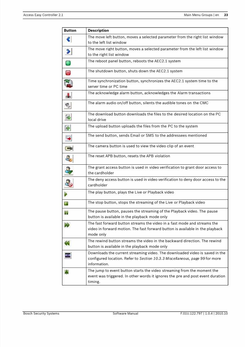
5.3 Usage of the buttons
The table below shows the functions of the action buttons available in AEC2.1 webpage.
Button Description
The save button saves the current settings to the (Dynamic RAM) DRAM and
refreshes the current web page
The add button performs the following functions: -– carries out the addition process
– adds selected parameter to the list window
The delete button performs the following functions: -
– deletes all configurable parameters and sets it to default
– removes selected parameter from the list window
The previous button performs the following functions
– does not save the settings made on the current screen and
– brings up the previous screen
The edit button, edits the current parameter settings
7/18/2019 User_Guide___Instruction_Book_enUS_1385855115.pdf
http://slidepdf.com/reader/full/userguideinstructionbookenus1385855115pdf 23/194
Access Easy Controller 2.1 Main Menu Groups | en 23
Bosch Security Systems Software Manual F.01U.122.797 | 1.0.4 | 2010.10
The move left button, moves a selected parameter from the right list window
to the left list window
The move right button, moves a selected parameter from the left list window
to the right list window
The reboot panel button, reboots the AEC2.1 system
The shutdown button, shuts down the AEC2.1 system
Time synchronization button, synchronizes the AEC2.1 system time to the
server time or PC time
The acknowledge alarm button, acknowledges the Alarm transactions
The alarm audio on/off button, silents the audible tones on the CMC
The download button downloads the files to the desired location on the PC
local driveThe upload button uploads the files from the PC to the system
The send button, sends Email or SMS to the addressees mentioned
The camera button is used to view the video clip of an event
The reset APB button, resets the APB violation
The grant access button is used in video verification to grant door access to
the cardholder
The deny access button is used in video verification to deny door access to the
cardholder
The play button, plays the Live or Playback video
The stop button, stops the streaming of the Live or Playback video
The pause button, pauses the streaming of the Playback video. The pause
button is available in the playback mode only
The fast forward button streams the video in a fast mode and streams the
video in forward motion. The fast forward button is available in the playback
mode only
The rewind button streams the video in the backward direction. The rewind
button is available in the playback mode only
Downloads the current streaming video. The downloaded video is saved in the
configured location. Refer to Section 10.3.3 Miscellaneous, page 99 for more
information.
The jump to event button starts the video streaming from the moment the
event was triggered. In other words it ignores the pre and post event duration
timing.
Button Description

7/18/2019 User_Guide___Instruction_Book_enUS_1385855115.pdf
http://slidepdf.com/reader/full/userguideinstructionbookenus1385855115pdf 24/194
24 en | Main Menu Groups Access Easy Controller 2.1
F.01U.122.797 | 1.0.4 | 2010.10 Software Manual Bosch Security Systems
The snapshot button is used to take a still image from the streaming video. The
image file is saved in the configured location. Refer to
Section 10.3.3 Miscellaneous, page 99 for more information.
The view report button is used to preview the configured report.
Button Description

7/18/2019 User_Guide___Instruction_Book_enUS_1385855115.pdf
http://slidepdf.com/reader/full/userguideinstructionbookenus1385855115pdf 25/194
Access Easy Controller 2.1 Activity | en 25
Bosch Security Systems Software Manual F.01U.122.797 | 1.0.4 | 2010.10
6 Activity
The Activity menu relates to the transactions generated by the AEC2.1 system and the video
features available in AEC2.1. The activity menu also relates to the manual control of the
system hardware.
The different features of the activity menu are explained in the following sections.
The Activity main menu consists of the following submenus:
– Transactions
– Device Control
– Default Settings
The three submenus are explained in detail in the following pages.
6.1 Transactions
The transactions submenu lists all the transactions or events triggered by the AEC2.1. Every
activity transaction such as Door Forced Open, Door Held Open, Access Granted, Access
Denied etc. are captured by AEC2.1 and displayed on the transactions web page in real-time
mode with the transaction occurrence date and time.
The transactions window consists of two window panes, the left pane and the right pane. The
left pane displays the transactions performed by AEC2.1 and the right pane displays the
online swipe, surveillance and camera monitoring features.
The transactions are categorized into different groups based on the event triggered or actions
performed on the AEC2.1. The transactions are categorized as follows: All, Alarm, Valid &
Alarm, Restore & Alarm, Time Attendance, APB and Video Verification. You can select a
specific transaction event or view all the transactions by selecting the All tab.
AEC2.1 can store up to 100,000 activity transactions and the Alarm transactions window is
the default screen for AEC2.1
Note: The default view of the transaction screen can be changed in the default settings page
of the activity menu. Refer to Section 6.3 Activity - Default Settings, page 45 for more details.
The screen below shows the transaction window with the All tab selected. You can select a
transaction group by selecting the transaction group tab you want to view.

7/18/2019 User_Guide___Instruction_Book_enUS_1385855115.pdf
http://slidepdf.com/reader/full/userguideinstructionbookenus1385855115pdf 26/194
26 en | Activity Access Easy Controller 2.1
F.01U.122.797 | 1.0.4 | 2010.10 Software Manual Bosch Security Systems
The transactions webpage displays the details of the event triggered or the action performed
on the AEC2.1 system. The transactions webpage lists the name, card number, location
where the event or action was performed, the date and time when the event or the action was
performed and the description of the event or action performed.
A camera icon is displayed along the transactions row if a camera is configured for the
location. Click the camera icon to view the recorded events or action video clip. These
event videos can be downloaded to the PC for later investigation. The videos are recorded in
the video device and not on the AEC2.1 system.
You can view the cardholder's profile by moving the pointer along the card number column.
This feature is available in all the transaction groups. The screen below shows an example of
the cardholder's profile details as you move along the card number column.
The cardholders profile window also shows the Reset APB button if a cardholder has APB
violation. You can reset the Anti-Passback violation for the cardholder by clicking the Reset
APB button.

7/18/2019 User_Guide___Instruction_Book_enUS_1385855115.pdf
http://slidepdf.com/reader/full/userguideinstructionbookenus1385855115pdf 27/194
Access Easy Controller 2.1 Activity | en 27
Bosch Security Systems Software Manual F.01U.122.797 | 1.0.4 | 2010.10
Note: You should have the access rights to reset the anti-passback option. Refer to
Section 8.4 Reset APB, page 69 for more details.
The features of activity transactions are as follow:-
– All Alarm transactions have red colored text wording while other transactions have black
colored text wording.
– Click the acknowledge button to acknowledge the alarm transactions. Once the
acknowledge button is clicked the alarm audio is silenced. The text of the alarm
transactions remain red even after the transactions are acknowledged.
– When the web page refreshes or is acknowledged, either automatically or through user
intervention the transactions background is replaced with grey background.
All the alarm transaction tabs (All, Alarm, Valid & Alarm, Restore & Alarm) consists of two
action buttons namely the acknowledge button and the speaker on/off button . Click
the acknowledge button to acknowledge the alarm transactions.
The AEC2.1 system sends a beep sound every time there is a transaction in the system. Click
the speaker on/off button to mute the beep sound.
The available Transaction groups are explained in detail below.
6.1.1 All
Displays all the transactions performed by the AEC2.1 system. The screen below shows the
All transactions window. The transactions page is explained in detail in the previous
paragraphs.
The Choose Location dropdown at the top of the page lists all the doors configured to the
system. You can configure a group of doors as a set in Setting - Door Group… option available

7/18/2019 User_Guide___Instruction_Book_enUS_1385855115.pdf
http://slidepdf.com/reader/full/userguideinstructionbookenus1385855115pdf 28/194
28 en | Activity Access Easy Controller 2.1
F.01U.122.797 | 1.0.4 | 2010.10 Software Manual Bosch Security Systems
in the choose location dropdown. Select Setting - Door Group… from the Choose Location
dropdown as shown below.
The screen below appears to select the doors to be added to the Door Group.
Select the check box corresponding to the respective doors which has to be configured in the
Door Group set. Click the save button to save the locations in the door group. Select the
All Items option if you want to select all the doors in the locations list to the door group. After
selecting the required doors click the save button to save the settings. Click the back
button to cancel the settings and return to the transactions page.
After saving the settings the web page returns to the Transactions main page. Select a
location from the Choose Location dropdown to view the transactions/events of the AEC2.1
system at the selected location.
In the All transactions window, all the alarm transactions have red colored text while other
transactions have black colored text.
6.1.2 Alarm
NOTICE!
The configured location is user based and is available to the user who configured the door
group.

7/18/2019 User_Guide___Instruction_Book_enUS_1385855115.pdf
http://slidepdf.com/reader/full/userguideinstructionbookenus1385855115pdf 29/194
Access Easy Controller 2.1 Activity | en 29
Bosch Security Systems Software Manual F.01U.122.797 | 1.0.4 | 2010.10
Displays the alarm events triggered by the system. Examples of Alarm transactions include
Access Denied, Door Held Open, Panel Tamper, Duress etc. For a detailed list on Alarm
transaction, refer to Section 25.1 Activity Transactions, page 190.
When any of the Alarm Activity transactions is transacted, an alerting audio tone is sent to the
Central Monitoring Computer (CMC). Ensure that the CMC's audio system is in working order
and the volume is set to a reasonable level.
The working procedure and the features available in Alarm transaction group is the same as
explained in the All transactions group. Refer to Section 6.1.1 All, page 27 for more
information about the software interface and the features available in the Alarm tab.
6.1.3 Valid & Alarm
Displays transactions performed by the system. Examples of Valid transactions include
Access Granted, Turn On, Disarmed, Duration On etc. For a detailed list on Valid transaction,
refer to Section 25.4 Valid Activity, page 190.
The working procedure and the features available in Valid & Alarm is the same as explained in
the All transactions group. Refer to Section 6.1.1 All, page 27 for more information about the
software interface and the features available in the Valid & Alarm tab.
6.1.4 Restore & Alarm
Displays the Alarm and Restored transactions performed by the system. Examples of Restored
transactions include Door Closed, Tamper Restored, Alarm Restored and Power Restored.
For a detailed list on Restored transaction, refer to Section 25.3 Restore Activity, page 190.
The working procedure and the features available in Restore & Alarm is the same as explainedin the All transactions group. Refer to Section 6.1.1 All, page 27 for more information about
the software interface and the features available in the alarm tab.
6.1.5 Time Attendance
Displays only Time Clocking transactions. Examples of Time Attendance transactions include
Clock In and Clock Out.
The working procedure and the features available in Time Attendance is the same as
explained in the All transactions group. Refer to Section 6.1.1 All, page 27 for more
information about the software interface and the features available in the time attendance tab.
6.1.6 APB
Displays the list of cardholder's name who are currently present in the APB zone. Refer to the
Section 8.4 Reset APB, page 69 for more information about Anti Passback.
The APB Zone dropdown at the top of the page lists all the APB Zones configured in the
system. Select a Zone from the Alarm Zone dropdown to view the list of cardholder’s who are
in the selected APB zone.

7/18/2019 User_Guide___Instruction_Book_enUS_1385855115.pdf
http://slidepdf.com/reader/full/userguideinstructionbookenus1385855115pdf 30/194
30 en | Activity Access Easy Controller 2.1
F.01U.122.797 | 1.0.4 | 2010.10 Software Manual Bosch Security Systems
6.1.7 Video Verification
The video verification page displays the live video of the access point for comparison with the
cardholder's photo. This allows the door operator to grant or deny access to the cardholder
via webpage manually after verification. In an event where there is no action and the time-out
occurs, grant access or deny access is provided based on the option configured in the door
settings menu. Refer to the Section 9 Door Settings (Card Reader Settings), page 71 for more
information.
If the user is in transaction view page (All, Alarm, Valid & Alarm, Restore & Alarm, Time
Attendance or APB) and upon receiving access request event the tab will automatically
switch to the video verification tab.
Video verification feature can be enabled or disabled based on schedules. Refer to
Section 9.5.1 Verification Camera Setting, page 87 for more information.
Note: A maximum of three cameras can be configured to a card reader, input/output point or
advance IO function block.
The screen below shows the video verification page.
Click the grant access button to grant door access to the cardholder or click the deny
access button to deny door access to the cardholder.
This view shows the Live video of all the cameras configured to the reader. Double click on
the main video to view the full screen video or select any small video at the bottom to view the
video in the main window.

7/18/2019 User_Guide___Instruction_Book_enUS_1385855115.pdf
http://slidepdf.com/reader/full/userguideinstructionbookenus1385855115pdf 31/194
Access Easy Controller 2.1 Activity | en 31
Bosch Security Systems Software Manual F.01U.122.797 | 1.0.4 | 2010.10
The pending list at the bottom of the video verification tab lists the name and location of the
cardholder waiting for door access at different configured locations. Select each cardholder
from the list to grant or deny door access. The number of items is equal to the number of
cardholders waiting for access rights.
The grant access and deny access button will be disabled if the cardholder in the pending list
has been granted or denied access by another user.
Before the cardholder in the pending list is granted or denied access, another user flashes the
card on the same location it will overwrite the existing cardholder details in the pending list to
the latest cardholder details.
The current date and time is displayed at the top right of the page and the location of the
cardholder waiting for door access is described besides the video verification text. A sample
video verification window is shown below for reference.
In the earlier example as soon as Maria is granted or denied access her transaction can be
viewed in the online swipe window and Sachin’s video clips are displayed in the video
verification window.
6.1.8 Online Swipe
The online swipe function lists the last three valid cardholders with photo who tried to access
the system. The online swipe tab lists the cardholder's profile and a button to reset APB if the
cardholder has APB violation.
The screen below shows the Online Swipe window.

7/18/2019 User_Guide___Instruction_Book_enUS_1385855115.pdf
http://slidepdf.com/reader/full/userguideinstructionbookenus1385855115pdf 32/194
32 en | Activity Access Easy Controller 2.1
F.01U.122.797 | 1.0.4 | 2010.10 Software Manual Bosch Security Systems
In the online swipe window all the alarm transactions and access denied events, APB violating
transactions are represented with a red border along the cardholder’s photo as shown below.
The invalid card actions are not recorded or represented in the online swipe window.
For example in the preceding screenshot Maria Robinson is denied access due to APB
violation, click the Reset APB button to reset her APB violation. After resetting the APB
settings the cardholder can use the card again with the same access rights provided. The
screen below shows the reset option in the transactions and online swipe window. You can
reset the APB settings in the transactions and online swipe window.

7/18/2019 User_Guide___Instruction_Book_enUS_1385855115.pdf
http://slidepdf.com/reader/full/userguideinstructionbookenus1385855115pdf 33/194
Access Easy Controller 2.1 Activity | en 33
Bosch Security Systems Software Manual F.01U.122.797 | 1.0.4 | 2010.10
Note: Only authorized users can reset APB violation.
This tab also provides an option to see the list of cardholder's who tried to access the system
at a particular door or group of doors.
The Choose Location dropdown at the top of the page lists all the doors configured to the
AEC2.1 system. You can configure a group of doors as one door group in Setting - Door
Group… option available in the Choose Location dropdown. Select Setting - Door Group…
from the Choose Location dropdown as shown below.
The screen below pops up to select the doors to be added to the Door Group.

7/18/2019 User_Guide___Instruction_Book_enUS_1385855115.pdf
http://slidepdf.com/reader/full/userguideinstructionbookenus1385855115pdf 34/194
34 en | Activity Access Easy Controller 2.1
F.01U.122.797 | 1.0.4 | 2010.10 Software Manual Bosch Security Systems
Select the check box corresponding to the respective doors which has to be configured in the
Door Group set. Click the save button to save the locations in the door group. Select the
All Items option if you want to select all the doors in the location list to the door group. After
selecting the required doors click the save button to save the settings. Click the back
button to cancel the settings and return to the transactions page.
6.1.9 Surveillance
When an alarm event is triggered the surveillance window will automatically display the
surveillance Live video of the event location and the event details, if a surveillance camera is
configured for the event location. In the surveillance window you can view the Live and
Playback videos of the configured cameras. You can also compare the Live and Playback
videos in the surveillance window. The surveillance camera for door is set in the door settings
option, refer to Section 9 Door Settings (Card Reader Settings), page 71 for more information.
The screen below shows the surveillance screen in the Live mode.
The table below lists the function buttons available in the surveillance window of the AEC2.1
system. The buttons mentioned in the table below have the same functionality in all the video
feature tabs.
NOTICE!
If an optional camera is configured for the event location without configuring a surveillance
camera, it is considered as no surveillance camera is configured for the event location.

7/18/2019 User_Guide___Instruction_Book_enUS_1385855115.pdf
http://slidepdf.com/reader/full/userguideinstructionbookenus1385855115pdf 35/194
Access Easy Controller 2.1 Activity | en 35
Bosch Security Systems Software Manual F.01U.122.797 | 1.0.4 | 2010.10
The Auto Popup checkbox must be selected for the window to automatically switch to
surveillance window when there is an alarm event. If this check box is not checked then the
surveillance window will not switch automatically when there is an event. It is always
advisable to check this box as this helps in monitoring the events.
The event details section specifies the status, location and Date/Time of the triggered event.
The Status field refers to the current status of the event for example Access Denied etc. The
Location field refers to the location where the event is triggered. The Date/Time field refers
to the date and time when the event is triggered.
You can view the Live and Playback mode in this window. Along the mode description field
you can see two function buttons namely the Compare button and the Toggle Live/Playback
button.
Button Function
Compares the Live and Playback video
Toggles between the Live and Playback video
Plays the video. Starts the video streaming
Pauses the video streaming and this option is available in the Playback mode
only
Stops the video display or video streaming
The rewind button streams the video in the backward direction. The rewind
button is available in the Playback mode only
The fast forward button streams the video in a fast mode and streams the video
in forward motion. The fast forward button is available in the Playback mode
only
Downloads the current streaming video. The downloaded video is saved in theconfigured location. Refer to Section 10.3.3 Miscellaneous, page 99 for more
information.
The jump to event button starts the video streaming from the moment the event
was triggered. In other words it ignores the pre and post event duration timing.
Refer to Section 10.3.3 Miscellaneous, page 99 for more information.
The snapshot button is used to take a still image from the streaming video. The
image file is saved in the configured location. Refer to
Section 10.3.3 Miscellaneous, page 99 for more information.
Camera 1 configured to the system. This camera is also known as main
surveillance camera.
Camera 2 configured to the system. This camera is also known as Optional
camera 1.
Camera 3 configured to the system. This camera is also known as Optional
camera 2.

7/18/2019 User_Guide___Instruction_Book_enUS_1385855115.pdf
http://slidepdf.com/reader/full/userguideinstructionbookenus1385855115pdf 36/194
36 en | Activity Access Easy Controller 2.1
F.01U.122.797 | 1.0.4 | 2010.10 Software Manual Bosch Security Systems
The toggle button toggles between the Live and Playback mode. The toggle button
switches between Live mode and Playback mode . The function buttons in the Live
and Playback mode are explained in the earlier table. The Live video option displays the live
video of the selected camera and the playback option displays the event video with the pre
and post event duration. Refer to Section 10.3.3 Miscellaneous, page 99 for more information.
You can view the live or playback video of all the cameras configured to the same reader as
the surveillance camera. The camera selection icons are available at the bottom of the
surveillance window.The default surveillance camera is set in the door settings menu. Refer to
Section 9 Door Settings (Card Reader Settings), page 71.
The screen below shows the surveillance window in Playback mode.
At the bottom of the surveillance window you will see the play, stop, snapshot and export
video clip buttons. Click the play button to start the video streaming, stop button to end the
video streaming, snapshot button to capture a still image from the streaming video and
export video clip to download the streaming video.
The Playback mode consists of more function buttons namely pause, rewind, forward and
jump to event. Click the pause button to pause the video streaming, rewind button to stream
the video in the backward direction, forward button to stream the video in the forward
direction, jump to event button to start the video streaming from the moment the event was
triggered.
NOTICE!
The pause button , rewind button , forward button and jump to event are
available in Playback mode only.

7/18/2019 User_Guide___Instruction_Book_enUS_1385855115.pdf
http://slidepdf.com/reader/full/userguideinstructionbookenus1385855115pdf 37/194
Access Easy Controller 2.1 Activity | en 37
Bosch Security Systems Software Manual F.01U.122.797 | 1.0.4 | 2010.10
A compare option is provided in the surveillance tab to compare the live and playback video
of the selected camera. Click the compare button to compare the Live video and
Playback video simultaneously. The playback video starts and ends the video display with the
pre and post timer settings. Refer to Section 10.3.3 Miscellaneous, page 99 for setting the pre
and post timer settings.
The screen below shows the compare window.
The function buttons have the same functionality as explained in the earlier paragraphs. Click
the back button to return to the Transactions | surveillance page.
Note: Double click on the video in the Live and Playback mode to view the enlarged video.
Note: The exported videos can be viewed using the player available in BOSCH VideoSDK
folder on the utility CD.
6.1.10 Camera Monitoring
The camera monitoring tab is used to monitor the cameras configured to the AEC2.1 system.
When you select the camera monitoring tab you can view the live or the playback video for a
selected date and time.
The screen below shows the camera monitoring screen in the Live mode.

7/18/2019 User_Guide___Instruction_Book_enUS_1385855115.pdf
http://slidepdf.com/reader/full/userguideinstructionbookenus1385855115pdf 38/194
38 en | Activity Access Easy Controller 2.1
F.01U.122.797 | 1.0.4 | 2010.10 Software Manual Bosch Security Systems
Select a camera from the Live View dropdown, the dropdown lists all the cameras configured
to the AEC2.1 system. The function keys at the bottom of the preview window is the same as
explained in the surveillance menu. Refer to Section 6.1.9 Surveillance, page 34 for more
information about the function keys.
The screen below shows the camera monitoring window in the playback mode.

7/18/2019 User_Guide___Instruction_Book_enUS_1385855115.pdf
http://slidepdf.com/reader/full/userguideinstructionbookenus1385855115pdf 39/194
Access Easy Controller 2.1 Activity | en 39
Bosch Security Systems Software Manual F.01U.122.797 | 1.0.4 | 2010.10
Select a camera from the Playback dropdown, the dropdown lists all the cameras configured
to the AEC2.1 system.
When you are in the playback view, a date and time text box appears as shown above to view
the earlier recorded event videos. Click the Date Selector button to select a date, and a
pop up appears as shown below.
Select the date to view the video of a recorded event. The selected date appears in the Date
box. Select the hour, minute and second from the respective dropdowns. Select a duration
from the duration dropdown. After all the settings are made the surveillance window will start
streaming the video.
If a duration is set the surveillance window will play video for the set duration only.
If there are no videos in the selected date and time then the AEC 2.1 did not encounter any
event on the selected date or time, try again with another date and time.
The function keys at the bottom of the preview window is the same as explained in the
surveillance menu. Refer to Section 6.1.9 Surveillance, page 34 for more information about the
function keys.
Note: Double click on the video in the Live and Playback mode to view the enlarged video.
Note: The exported videos can be viewed using the player available in BOSCH VideoSDK
folder on the utility CD.
6.2 Device Control
The device control is a submenu of the Activity menu. The device control submenu refers to
the manual door settings of the AEC2.1 system. The device control menu consists of three
tabs namely Door Control, Input Control and Output Control.
The three submenus are explained in detail in the following pages.
6.2.1 Door Control
The Door Control option allows you to check the status of the doors and momentarily unlock/
lock the door without having to be present at the door location. This is a manually operated
control and has priority over the system control. However, the system will resume normal
operation once it encounters a valid schedule interval.
Let's explain this with an example

7/18/2019 User_Guide___Instruction_Book_enUS_1385855115.pdf
http://slidepdf.com/reader/full/userguideinstructionbookenus1385855115pdf 40/194
40 en | Activity Access Easy Controller 2.1
F.01U.122.797 | 1.0.4 | 2010.10 Software Manual Bosch Security Systems
The door is scheduled as follows Unlock Door Start - 0830 hrs and End - 1730 hrs.
The manual control is as follows
Unlock door 0730 hrs and Lock door at 0800 hrs
Lock door at 1230 hrs and Unlock door at 1315 hrs
The figure below shows the status of the door during the schedule time and when there is a
manual door control
Notice that the system resumes normal operation according to Schedule at 0830 hrs and
1731 hrs.
To activate Door Control
Click the link Activity > Device Control. In the Device Control main page select the tab Door to
set the manual door settings for the door. The Door tab is the main page of the device control
menu. The screen below shows the Door Control page.
The door control page mainly consists of three columns namely Description, Status and
Manual Action. The Description column provides the door description.
Door Locked Door Unlocked Door Locked
0830hrs 1731hrs
Door Status
according toSchedule
Manual Door
Controlcommand sent
Resultant Door Status
1. Unlock Door at 0730hrs
2. Lock Door at 0800hrs
3. Lock Door at 1230hrs
4. Unlock Door at 1315hrs
0730hrs 0800hrs
0830hrs0000hrs
1230hrs 1315hrs
2359hrs1731hrs
Legend:
Door is permanently Unlocked
Door is permanently Locked

7/18/2019 User_Guide___Instruction_Book_enUS_1385855115.pdf
http://slidepdf.com/reader/full/userguideinstructionbookenus1385855115pdf 41/194
Access Easy Controller 2.1 Activity | en 41
Bosch Security Systems Software Manual F.01U.122.797 | 1.0.4 | 2010.10
The Status column refers to the current status of the door. Move along the icon in the status
column to see the icon representation or tool tip.
The Manual Actions column provides radio buttons to select the manual action to be
performed. The description of the first radio button is to retain the door action and by default
the No Change radio button is selected. The description of the second radio button is the
opposite of the current status and toggles between Lock and Unlock. The third radio button,
Momentary Unlock, is used to send a command to momentarily unlock the door for the
duration as specified in the Door Strike Timer. This command is only effective when the
current status of the door is locked.
To control the Doors manually
1. Select the desired action radio button (see the below NOTICE).
2. Click the save button to send the command. The web page refreshes and reflects
the new status.
6.2.2 Input Control
The Input Control menu allows you to check the status of all the Input Points and sends a
command to Arm/Disarm the device manually. This is a manually operated control and has
priority over the system set control. However, the system will resume normal operation once
it encounters a valid schedule interval.
For configuration of system control, refer to Section 13 Input State, page 124.
Let's explain this with an example
The door is scheduled as follows Unlock Door Start - 0830 hrs and End - 1730 hrs.
The manual control is set as follows
Disarm device 0730 hrs and Arm Device at 0800 hrs
Arm Device at 1230 hrs and Disarm device at 1315 hrs
The figure below shows the status of the door during the schedule time and when there is a
manual door control
NOTICE!
Only readers configured as Entry Readers will be shown in the Device Control > Door web
page.
NOTICE!
Select only door(s) that you want to send command to. The current status of the door for a
Momentarily Unlocked command will not show the status.

7/18/2019 User_Guide___Instruction_Book_enUS_1385855115.pdf
http://slidepdf.com/reader/full/userguideinstructionbookenus1385855115pdf 42/194
42 en | Activity Access Easy Controller 2.1
F.01U.122.797 | 1.0.4 | 2010.10 Software Manual Bosch Security Systems
Notice the system resumes normal operation according to Schedule at 0830 hrs and 1731 hrs.
To activate Input Control
Click the link Activity > Device Control. In the Device Control main page select the Input tab
to set the manual input point settings. The screen below shows the Input Device Control
page.
The input control page allows you to view the current status of all assigned Input Points.
The input control consists of mainly three columns namely Description, Status and Manual
Action. The Description column provides the door description.
The Status column refers to the current status of the input point. Move along the icon in the
status column to see the icon representation or tool tip.
The horizontal strip provides the Alarm Zone to which the Input Points belong. In this case,
Undefined Input Point 1 belongs to Alarm Zone 1 and Undefined Input Point 2 is an
independent input point.
Alarm ZoneArmed
0830hrs 1731hrs
Alarm Zone Statusaccording to
Schedule
Manual Input
Controlcommand sent
Resultant Alarm Zone
Status
1. Disarm Zone at 0730hrs
2. Arm Zone at 0800hrs
3. Arm Zone at 1230hrs
4. Disarm Zone at 1315hrs
0730hrs 0800hrs
0830hrs0000hrs
1230hrs 1315hrs
2359hrs1731hrs
Legend:
All Input Points within the Alarm Zone are Disarmed
Alarm ZoneArmed
Alarm Zone
Disarmed
All Input Points within the Alarm Zone are Armed

7/18/2019 User_Guide___Instruction_Book_enUS_1385855115.pdf
http://slidepdf.com/reader/full/userguideinstructionbookenus1385855115pdf 43/194
Access Easy Controller 2.1 Activity | en 43
Bosch Security Systems Software Manual F.01U.122.797 | 1.0.4 | 2010.10
In the preceding example Undefined Inpoint 1 belongs to Alarm Zone 1. Select a zone from
the input points dropdown to arm or disarm the input points in an alarm zone. The screen
below shows an example of an input point set in an alarm zone.
Click the arm or disarm button to arm/disarm the input points set in the alarm zones.
The Manual Actions column provides radio buttons to select the manual action to be
performed. The description of the first radio button is to retain the door alarm zone and by
default the No Change radio button is selected. The description of the second radio button is
the opposite of the current status and toggles between Disarm now and Arm now.
To control the Input points
1. Select the desired action radio button
2. Click the save button to arm the Input Points. The web page will refresh to reflect
the new status.
6.2.3 Output Control
The Output Control menu allows you to check the status of all the Output Points and sends a
command to turn on/off the output points manually. This is a manually operated control and
has priority over the system set control. However, the system will resume normal operation
once it encounters a valid schedule interval.
Let's explain this with an example
The door is scheduled as follows Unlock Door Start - 0830 hrs and End - 1730 hrs.
The manual control is as followsOn Output 0730hrs and Off Input at 0800hrs
Off Input at 1230hrs and On Output at 1315hrs
The figure below shows the status of the door during the schedule time and when there is a
manual door control

7/18/2019 User_Guide___Instruction_Book_enUS_1385855115.pdf
http://slidepdf.com/reader/full/userguideinstructionbookenus1385855115pdf 44/194
44 en | Activity Access Easy Controller 2.1
F.01U.122.797 | 1.0.4 | 2010.10 Software Manual Bosch Security Systems
Notice the system resumes normal operation according to Schedule at 0830 hrs and 1731 hrs.
To activate Output Control
Click the link Activity > Device Control. In the Device control main page click the Output tab to
set the manual output settings. The screen below shows the Output Device Control page.
The output control main page consists of mainly three columns namely door Description,
Status and Manual Action. The Description column provides the door description.
The Status column refers to the current status of the output point. In the status column On
(glowing output point) status indicates that the Output Point is On and Off status indicates
that the Output Point is Off . The manual actions column provides radio buttons to select the
manual action that can be performed on the device. The second radio button is the opposite
of the current status and toggles between On and Off .
The third radio button, Duration On or Duration Off reflects the opposite of the current
status, and is used to send command to turn on or turn off the Output Point for duration as
depicted in the Duration field in Output Setup menu item. Refer to the Chapter on Output
Setup for details.
Output Off
0830hrs 1731hrs
Output Statusaccording to
Schedule
Manual Output Control
command sent
Resultant Output Status
1. On Output at 0730hrs
2. Off Input at 0800hrs
3. Off Output at 1230hrs
4. On Output at 1315hrs
0730hrs 0800hrs
0830hrs0000hrs
1230hrs 1315hrs
2359hrs1731hrs
Legend:
Output Points On
Output Points Off
Output Off Output On

7/18/2019 User_Guide___Instruction_Book_enUS_1385855115.pdf
http://slidepdf.com/reader/full/userguideinstructionbookenus1385855115pdf 45/194
Access Easy Controller 2.1 Activity | en 45
Bosch Security Systems Software Manual F.01U.122.797 | 1.0.4 | 2010.10
To control the Output Points
1. Select the desired radio button(s) (see the below NOTICE).
2. Click the save button to save the settings. The web page will refresh to reflect the
new status.
6.3 Activity - Default Settings
The activity menu consists of the default settings submenu, which controls the settings of the
transactions window. In the default settings window you can edit the number of transactions
to view and the default transaction view. The screen below shows the default settings screen.
6.3.1 To edit Transactions Setting
1. Select the number of transactions to view from the Number of Transactions to View
dropdown list. The number selected here is the number of transactions you will be ableto see in the transactions page. Number of transactions can range from 10 to 70 in the
steps of 10.
2. Select the appropriate view from the Default Activity View dropdown list. There are 5
types of transaction views namely; All, Alarm, Valid & Alarm, Restore & Alarm and Time
Attendance.
The selected view is the default page for the transactions menu and the default screen of
AEC2.1.
3. Click the save button to save the settings.
Note: The number of records to view on screen is configurable to a maximum of 70 records.
These settings are effective immediately and is reflected the next time you log on the
transactions page.
NOTICE!
Select only Output Point(s) that you want to send command to. The current status of the
Output Point for a Duration On or Duration Off command will not show the true status after
the Duration has elapsed, unless you refresh the web page by clicking the save button.

7/18/2019 User_Guide___Instruction_Book_enUS_1385855115.pdf
http://slidepdf.com/reader/full/userguideinstructionbookenus1385855115pdf 46/194
46 en | Card Administration Access Easy Controller 2.1
F.01U.122.797 | 1.0.4 | 2010.10 Software Manual Bosch Security Systems
7 Card Administration
Card administration refers to the parameters that control the access rights of the cards. Card
parameters contain information such as which card reader a cardholder can access at a
specified schedule. The card parameters are used to configure additional card information
like Department, Arm/disarm, Access Group …etc.
This chapter describes the features of the Card parameter function and the card assignment,
enrollment, adding batch cards and database import/export procedure.
The cards main menu consists of the following submenus:-
– Card Administration
– Access Groups
– Card Format
– Department
– Reset APB
– Default setting
The above submenus are explained in detail in the following pages.
Card Administration refers to the access rights of the cards and the cardholder. Card
administration consists of the following card functionality parameters
– Assignment
– Enrollment
– Import/Export
– Batch Card
The above card parameters are explained in detail in the following pages.
7.1 Card Assignment
Card Assignment refers to adding or editing card details. The card assignment parameter also
refers to the access rights of the card and the schedule when a card can be accessed by the
card reader.
Card assignment menu consists of the following card parameters: -
Card Details
– Card Number
– User Name
NOTICE!
AEC2.1 supports a maximum capacity of 20,480 cardholders.
NOTICE!
As the AEC2.1 supports different types of Card Formats, such as BOSCH 37-Bits, 26-Bits, 34-
bits or other customized format, there will be an overlapping of card number range. There is apossibility to assign the same Card Number(s) with different Facility Code. The AEC2.1
processes the card number along with the Facility code.

7/18/2019 User_Guide___Instruction_Book_enUS_1385855115.pdf
http://slidepdf.com/reader/full/userguideinstructionbookenus1385855115pdf 47/194
Access Easy Controller 2.1 Card Administration | en 47
Bosch Security Systems Software Manual F.01U.122.797 | 1.0.4 | 2010.10
– Facility Code
– Card Format
– Department
– User Field 1 and User Field 2 (user definable field)
– Access Groups A and B
Card Functionality
– Cardholder Arm/Disarm rights
– Card Operations
– Card + PIN Operations
– User PIN
– Card Validation Period
– Dual Card Assignment
– Enrollment operation
The following pages explain the card details and card functionality features in detail.
To access the card assignment parameter click the link Card > Card Administration. In the
card administration main page, select the Assignment tab. The assignment tab is the default
page for the card administration menu.
The screen below shows the card assignment main page.
The card assignment main page provides an option to search for a card based on the card
number, name and the user fields. The search option is explained in detail in
Section 7.1.3 The Search Function, page 55.
The card assignment main page shows 20 card numbers in the page. To view different ranges
of card numbers click the card range links at the top right of the page.
Note: AEC2.1 supports a maximum of 20,480 cardholders.
To add or edit card number and its parameters
When the AEC2.1 is first installed, there is only one assigned User ID and Password. This
default User ID is called the Super-user and is usually assigned to the AEC2.1 System
Administrator. The AEC2.1 system administrator must configure the card parameters in the
AEC2.1 card database for the cardholder to gain access.

7/18/2019 User_Guide___Instruction_Book_enUS_1385855115.pdf
http://slidepdf.com/reader/full/userguideinstructionbookenus1385855115pdf 48/194
48 en | Card Administration Access Easy Controller 2.1
F.01U.122.797 | 1.0.4 | 2010.10 Software Manual Bosch Security Systems
Card assignment is frequently used to assign card number and access right to new employees
or block cards for employees who have resigned from the company.
7.1.1 Card Details
Card details refer to the card number, user name, department and the profile of the
cardholder. Follow the steps below to add a new card and to assign access rights to thecardholder.
1. Click the add button in the card assignment main page to add a new card. The Card
Assignment > Add main page shows the card number and user name text boxes.
2. Enter a card number in the Card Number field.
3. Enter the Cardholder's (User) Name in the User Name field.
4. The Card Assignment > Add main page consists of two card parameters or tabs namelyDetails and Functionality. Click the Details tab and the screen below appears.
5. Enter the facility code in the Facility code field. The Facility code is configured in the
Card > Default Settings page. Refer to Section 8.5 Card - Default Settings, page 70 for
more information.
6. Select the Card Format from the card format dropdown list. The card format is
configured in the Card > Card Format page. Refer to Section 8.2 Card Format, page 65 for
more information.
NOTICE!
The Card Number together with the Card Format and Facility Code is a unique field, so do not
enter duplicate information. The card number and the facility code are mandatory fields.

7/18/2019 User_Guide___Instruction_Book_enUS_1385855115.pdf
http://slidepdf.com/reader/full/userguideinstructionbookenus1385855115pdf 49/194
Access Easy Controller 2.1 Card Administration | en 49
Bosch Security Systems Software Manual F.01U.122.797 | 1.0.4 | 2010.10
7. Select the Department from the department dropdown list. The department is
configured in the Card > Department page. Refer to Section 8.3 Department, page 68 for
more information.
8. Enter the required details in User Field 1 and User Field 2.
9. Select the Access Grouping for the cardholder in Access Group A and/or Access Group
B from the dropdown list. Leave the entry blank if there is only one or no assignment. The
access group is configured in Card > Access Group page. Refer to Section 8.1 Access
Groups, page 64 for more information.
10. The cardholder photo uploaded here is used for the video verification feature. If this
photo matches with the cardholder's video from the identification camera at the access
door, then the door operator grants or denies door access according to the cardholder's
access rights. Click the browse button to upload the cardholder photo.
A browse window pops up as shown below.
NOTICE!The User Field 1 and User Field 2 are configured in Card > Default Settings page. Refer
Section 8.5 Card - Default Settings, page 70 for more information.
NOTICE!
Setting the access group allows the cardholder to access the door as scheduled in the access
group settings.

7/18/2019 User_Guide___Instruction_Book_enUS_1385855115.pdf
http://slidepdf.com/reader/full/userguideinstructionbookenus1385855115pdf 50/194
50 en | Card Administration Access Easy Controller 2.1
F.01U.122.797 | 1.0.4 | 2010.10 Software Manual Bosch Security Systems
a. Select a file and click the upload button. The following error message will pop
up if the file size is more than 5 KB.
b. Click the OK button and browse another file with a smaller file size.
11. Upload the photo and a preview can be seen in the Photo preview window as shown
below.
12. Click the save button to save the settings. Click the back button if you want to
cancel the settings and return to the card assignment main page.
7.1.2 Card Functionality
Card Functionality refers to the access rights and functionality of the cards such as Arm/
Disarm the door, access behavior and validation dates. Each card can be configured with
different access rights. Some of the settings of the card can be activated in co-ordination with
the card reader parameters such as Card + PIN mode. These settings can be modified at any
point of time.
NOTICE!
AEC2.1 supports image files with format JPEG and BMP
NOTICE!
The photo is necessary for the video verification feature. Refer to Section 6.1.7 Video
Verification, page 30 for more details.

7/18/2019 User_Guide___Instruction_Book_enUS_1385855115.pdf
http://slidepdf.com/reader/full/userguideinstructionbookenus1385855115pdf 51/194
Access Easy Controller 2.1 Card Administration | en 51
Bosch Security Systems Software Manual F.01U.122.797 | 1.0.4 | 2010.10
The screen below shows the card functionality page.
All the card functions are explained in detail below
Cardholder is able to Arm/Disarm
If this feature is checked, it implies that the cardholder is given the authority to arm/disarm a
specific Alarm Zone or All Alarm Zones as defined in the field. Select the alarm zone from the
Zone dropdown list.
This functionality works in conjunction with the reader that is set to arm/disarm the alarm
zone. Refer to Section 9.3.1 Door Output Settings (For Entry Reader, Entry and Arm/Disarm
Reader), page 78 for more details.
If this function is enabled on the cardholder, then the alarm zone will toggle from arm to
disarm or vice versa when the cardholder presses 0 before presenting the card to the card
reader. However if the cardholder presents the card to the reader without activating the arm/
disarm function on the reader keypad, it will unlock the door and disarm the alarm zone
depending on the cardholders access right.
Cardholder must abide by holiday schedules (to work in conjunction with Reader Options)
If this feature is checked, it implies the cardholders' access rights are different during
holidays. It works in conjunction with the Reader Options on holidays followed by the holiday
schedules. If checked, the 4 sets of Regular or Special Holiday schedules are used to operate
the access mode, e.g. Cardholder is allowed to access the controlled area during weekdaysand during office hours. However during holidays, the cardholder is allowed to access this
area as defined by the Holiday schedule intervals.
Allow exit reader usage only in accordance with time schedules
This mode is valid only if there is an exit reader. If this function is checked, the Reader will
allow the cardholder to exit the area within the valid Schedule intervals. When the function is
unchecked, the reader will allow the cardholder to exit the area at all times.
Card holder can enable enrollment operation
If this feature is checked, it implies the selected cardholders have the right to use their card
to activate a Reader to be in enrollment mode. Refer to Section 7.2 Card Enrollment, page 57
for more details.

7/18/2019 User_Guide___Instruction_Book_enUS_1385855115.pdf
http://slidepdf.com/reader/full/userguideinstructionbookenus1385855115pdf 52/194
52 en | Card Administration Access Easy Controller 2.1
F.01U.122.797 | 1.0.4 | 2010.10 Software Manual Bosch Security Systems
Disable card from all access permanently
If this feature is checked, it implies the cardholder will be denied access from the system
immediately. This feature is useful to prevent illegal access to the system if the cardholder
loses or misplaces the card
Card holder with one time access only
If this feature is checked, it implies the cardholder will have only one time access to thesystem. This means that after the card holder has gained access, the cardholder's access will
become invalid immediately. To gain access again, the AEC2.1 system administrator has to
reactivate the one time access right. This function is useful in a remote station delivery
application.
Ensure the Valid radio button is selected for the Access Status. After the card has been used
for one time access, the Access Status will expire immediately and the Access Status will be
updated to Expired automatically.
Card + PIN is required on Keypad readers
This mode works only when the Card Reader's PIN mode is set. If this feature is checked, it
implies the cardholder must enter the PIN after presenting the card to the reader to gain
access. The cardholder can configure up to 7 digits for the PIN.
When using it on the reader, the cardholder must enter the PIN followed by the ‘E’ key for C3
readers and S-Series reader or ‘#’ for HID compliant readers. For example, if the cardholder
configures less than 7 digits as the pin, for example ‘5566’, then the cardholder must enter
‘5566#’ for the PIN.
Enter user PIN (1-7 digits)
This field is to be used for the Card + PIN mode (default PIN code 1234000).
Extended duration for door access
This function is to facilitate special card holders to have extended duration for Door Strike
and Keypad Time-out. If this feature is checked, it allows the cardholder to keep the door
open for a longer time after a successful access is granted before a Door Held Open alarm is
activated. The Keypad Time-out duration is also extended by the selected time on top of the
normal Keypad Time-out duration. An example of such an application is for the handicapped
people who need a longer time to access the door.
To select the extended time duration, select the time in seconds from the dropdown list
beside the extended duration for door access. The range is from 0 to 255 seconds.
Card Validation Dates
This feature defines the start and end date parameters.
The Start Date is the date from when the card is valid and End Date is the date from when the
card is no longer valid. The card will not be able to access any door before the Start Date and
after the End Date.
Cards having such parameter settings are normally issued to contractors or temporary staff
who will only be allowed to access the controlled area for a known period of time. The usage
of this feature can be either one or the combination of both. You can define a card that only
allow access after a specified future date but doesn't have an expiry date. In this case, you
only select and set the Start Date but leave the End Date unchecked.

7/18/2019 User_Guide___Instruction_Book_enUS_1385855115.pdf
http://slidepdf.com/reader/full/userguideinstructionbookenus1385855115pdf 53/194
Access Easy Controller 2.1 Card Administration | en 53
Bosch Security Systems Software Manual F.01U.122.797 | 1.0.4 | 2010.10
Alternatively, you can define a card that is valid with immediate effect but is valid only for 2
days; in this case you can leave the Start Date unchecked but check and select the End Date.
Dual Card Assignment
This mode is useful if 2 cards are required to be presented in sequence to the Reader to
unlock the door. This mode works in conjunction with the Dual Card Configuration. Refer to
Section 9.4.3 Dual Card Configuration, page 85 for more information. The First Card has to be
presented first before the Second Card is presented, else the door will not unlock. A Don't
Care Card can act as the first or second card. In this setup here, you will need to define
whether a card is a First Card, Second Card or Don't Care Card, and which group it belongs
to. Cards from different groups cannot unlock the door.
Select the radio button besides Dual Card presentation sequence to enable this mode. You
will need to define whether a card is a First Card, Second Card or Don't Care Card from thedropdown list. You will also have to select the Dual Card Group ID from the dropdown list. 2
cards from the same Dual Card Group ID must be presented to the Reader to unlock the door.
The table below shows all the possible card combinations that can be presented to the
Reader.
To select Card Functionality
1. Select the Card Functionality tab and click the corresponding check boxes to show a tick
mark. To de-select the function click the checkbox again.
2. To assign the Alarm Zone, select the appropriate Alarm Zone from the Zone dropdown
list.
3. Click the appropriate radio button to show if the card is a valid card or an expired card
4. To edit User PIN code, highlight the default PIN code and enter the new User PIN code.
To select and edit Card Validation Period
1. To enable the Start Date, click the Start Date check box to show a tick mark. To deselect,
click the checkbox again.
NOTICE!
You must check the respective box for Start Date or End Date in order for it to be effective.
Possible card combination
First card Second Card
Don't Care Don't Care
First Card Don't Care
Don't Care Second Card
First Card Second Card
NOTICE!
You can enter 1 to 7 digits for the User PIN code. For security reason, every character entered
for the PIN code is represented by an dot.

7/18/2019 User_Guide___Instruction_Book_enUS_1385855115.pdf
http://slidepdf.com/reader/full/userguideinstructionbookenus1385855115pdf 54/194
54 en | Card Administration Access Easy Controller 2.1
F.01U.122.797 | 1.0.4 | 2010.10 Software Manual Bosch Security Systems
2. Select the appropriate Day from the calendar picker.
3. To enable the End Date, click on the End Date check box to show a tick mark. To de-
select, click the checkbox again.
4. Repeat step 2 for End Date. An example is shown below for your reference.
To Select and edit dual card assignment
This option is applicable for using two cards to initiate the access. This option allows the
system to switch back to single card access after using dual card for the first time or set to
Dual Card access at all time.
1. Click the link Card > Card Administration > Assignment > Functionality tab and Dual
Card Assignment option.
2. Select the Dual Card presentation sequence radio button and choose the card sequence
to set if the card is a First Card or Second Card. Select Don't care option is no sequence
is required.
3. Also select the Dual Card Group ID from the drop-down box.
4. If dual card is not assigned, click the radio button Dual card not assigned.
Click the save button to save the settings. Click the back button to cancel the
settings and return to the card assignment main page.
The card assignment main page consists of the edit and delete button. Click the edit
button to edit the card details and the card functionality settings. The edit card page is same
as the add card details and functionality web page.
Click the delete button to delete an existing card details.
NOTICE!
Date setting will not be updated if the corresponding check box is not checked. It will return
to the previous setting.
NOTICE!
Deleting a configuration will delete the item from the current setting and everywhere it is
configured.

7/18/2019 User_Guide___Instruction_Book_enUS_1385855115.pdf
http://slidepdf.com/reader/full/userguideinstructionbookenus1385855115pdf 55/194
Access Easy Controller 2.1 Card Administration | en 55
Bosch Security Systems Software Manual F.01U.122.797 | 1.0.4 | 2010.10
7.1.3 The Search FunctionThe Card Assignment main page allows you to search the card database for a particular card.
You can search the card either by Card Number, Name, User Field or any of the card details
value.
To find a particular Cardholder based on Name.
1. If you wish to find a Card Number whose Name is known, select the option Name from
the Option drop down box
2. Enter the first few characters of the person's name in the Search field and click the
search button. If you know the full name of the cardholder enter the full name in the
search field.
During the Search function, one of the following cases can happen:
a. If the name specified is not found in the card database, the No records found
message appears, or
b. If the result has only one match, the Card assignment page with the cardholders
name will appear, or
c. If the result yields more than one match, a window will appear below the function
field for further selection.
We will elaborate on case c. For example, lets search the database for Cardholder with
the name “Maria”.
a. Enter the word Maria in the Search field.
b. Click the search button and the following result will be displayed.
The database contains two Cardholders whose name satisfies the word “Maria”.
c. Click the edit button along the desired name to view and edit the cardholder details.
To find a particular Cardholder based on Card Number.
If you want to find a Cardholder's details whose Card Number is known, use the Search
function as shown below.
1. Select the Card Number option from the Option dropdown list.
2. Enter the exact Card Number in the Search field.

7/18/2019 User_Guide___Instruction_Book_enUS_1385855115.pdf
http://slidepdf.com/reader/full/userguideinstructionbookenus1385855115pdf 56/194
56 en | Card Administration Access Easy Controller 2.1
F.01U.122.797 | 1.0.4 | 2010.10 Software Manual Bosch Security Systems
3. Click the search button.
4. The card assignment main page appears with the list of card numbers entered.
To find a particular Cardholder based on User Field 1 or User Field 2.
1. If you wish to find a Card Number whose user field 1 or user filed 2 is known, select the
option User Field 1 or User Field 2 from the Option drop down box.
2. Enter the value in search field.
3. Click the search button.
4. The card assignment main page appears with the list of card numbers entered.
Advance Search
The advance search window allows you to search the card database more easily. The Advance
Search window is shown below.
Enter a value in any one field of the search window. You can search the card database on the
following parameters Card Number, Name, Card Format, Facility Code, User Field 1, User
Field 2, Department, Access Group A, Access Group B, Start date or End date. After
entering the value click the search button. The search result is displayed in the card
assignment main page.
Click the back button if you do not want to continue with the search option.
NOTICE!
If the card number specified is not configured in the card database, than No records found
message appears.
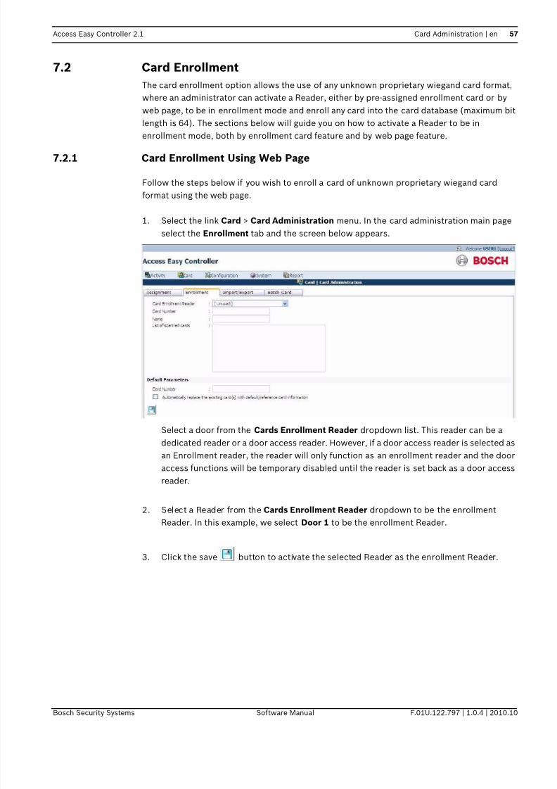
7/18/2019 User_Guide___Instruction_Book_enUS_1385855115.pdf
http://slidepdf.com/reader/full/userguideinstructionbookenus1385855115pdf 57/194
Access Easy Controller 2.1 Card Administration | en 57
Bosch Security Systems Software Manual F.01U.122.797 | 1.0.4 | 2010.10
7.2 Card Enrollment
The card enrollment option allows the use of any unknown proprietary wiegand card format,
where an administrator can activate a Reader, either by pre-assigned enrollment card or by
web page, to be in enrollment mode and enroll any card into the card database (maximum bit
length is 64). The sections below will guide you on how to activate a Reader to be in
enrollment mode, both by enrollment card feature and by web page feature.
7.2.1 Card Enrollment Using Web Page
Follow the steps below if you wish to enroll a card of unknown proprietary wiegand card
format using the web page.
1. Select the link Card > Card Administration menu. In the card administration main page
select the Enrollment tab and the screen below appears.
Select a door from the Cards Enrollment Reader dropdown list. This reader can be a
dedicated reader or a door access reader. However, if a door access reader is selected as
an Enrollment reader, the reader will only function as an enrollment reader and the door
access functions will be temporary disabled until the reader is set back as a door access
reader.
2. Select a Reader from the Cards Enrollment Reader dropdown to be the enrollment
Reader. In this example, we select Door 1 to be the enrollment Reader.
3. Click the save button to activate the selected Reader as the enrollment Reader.

7/18/2019 User_Guide___Instruction_Book_enUS_1385855115.pdf
http://slidepdf.com/reader/full/userguideinstructionbookenus1385855115pdf 58/194
58 en | Card Administration Access Easy Controller 2.1
F.01U.122.797 | 1.0.4 | 2010.10 Software Manual Bosch Security Systems
4. Present the card with unknown Wiegand Format to the enrollment Reader. The card that
has been presented to the enrollment Reader will appear in the box List of scanned
cards.
5. You can now assign any Card Number and Name to the card.
6. Highlight the card in the List of scanned cards that you are assigning the Card Number
and Name to and enter the card number and name in the appropriate field as shown
below.
7. Click the save button to save the card details.
7.3 Import/Export Function
This feature allows you to export or import the card database in a familiar CSV format.
NOTICE!
It is recommended that you assign a number to the card of unknown wiegand format
beforehand and stick a label on the card, so that it is easier to refer to the card number during
the card enrollment process.
NOTICE!
If you are using a door access reader as a temporary enrollment reader, after enrolling the
unknown wiegand card, it is required to reset the reader back to a door access reader.

7/18/2019 User_Guide___Instruction_Book_enUS_1385855115.pdf
http://slidepdf.com/reader/full/userguideinstructionbookenus1385855115pdf 59/194
Access Easy Controller 2.1 Card Administration | en 59
Bosch Security Systems Software Manual F.01U.122.797 | 1.0.4 | 2010.10
The import/Export function is also used as a backup and restores utility. Select the link Card >
Card Administration and in the card administration page select the tab Import/Export, the
screen below appears.
7.3.1 Exporting the Card Database
Follow the steps below to export the card database.
1. To export the card database, click the export button. A screen as shown below will
appear.
2. Save the file to a local hard disk or an external drive. Click the Save button and the
screen below appears.

7/18/2019 User_Guide___Instruction_Book_enUS_1385855115.pdf
http://slidepdf.com/reader/full/userguideinstructionbookenus1385855115pdf 60/194
60 en | Card Administration Access Easy Controller 2.1
F.01U.122.797 | 1.0.4 | 2010.10 Software Manual Bosch Security Systems
3. Select the drive you want to save the file in and give an appropriate File Name. Click the
save button to save the file.
4. Once the download is complete the screen below appears.
5. Click Open to view the file else click the Close button to close the window.
7.3.2 Importing the Card Database
Follow the steps below to import the above edited CSV file.
1. To import the card database, select a .CSV file using the Browse button or enter the
directory and the file name directly in the space provided beside Select a CSV file.
2. Select the checkbox besides Clear the current database and then import the cards if
you want to delete the existing database and import the new database.
3. Click the Import button to import the database to the system.
7.4 Batch Cards
Below sections describe the adding and deleting processes for Batch Cards.
7.4.1 Adding Batch Cards1. Select the link Cards > Card Administration. From the card administration main page
select the Batch Card tab.

7/18/2019 User_Guide___Instruction_Book_enUS_1385855115.pdf
http://slidepdf.com/reader/full/userguideinstructionbookenus1385855115pdf 61/194
Access Easy Controller 2.1 Card Administration | en 61
Bosch Security Systems Software Manual F.01U.122.797 | 1.0.4 | 2010.10
2. Enter the card number in the Card Number field (the number specified here will be the
starting number of the batch card operation and will be included).
3. The number in the Facility code is configured in Card > Default Settings, if the code is
different from the default, then change the facility code. Refer to Section 8.5 Card -
Default Settings, page 70 for more details. Enter 0 if the Card Format doesn't support
Facility Code.
4. Select the appropriate Card Format from the dropdown list. The Card format is
configured in the section Cards > Card Format menu. Refer to Section 8.2 Card Format,
page 65 for more details.
5. Enter the number(s) of card number to add in the Number of Cards field.
6. Click the add button. If there is no error during the card numbers addition, the Cards
added successfully message will be shown. Refer to Section 7.4.4 System Messages,
page 62 if other message are displayed.
7. Click the save button to return to the menu item first page.
8. Proceed to edit the newly added card number parameters.
7.4.2 To delete a Batch of Card Number
The procedures to delete a range of card numbers is similar to adding a batch of card
numbers. Instead of clicking the add button, click the delete button.
7.4.3 To add a Batch of Card Number with same data entries
This function allows addition of a range of card numbers with data entries copied from a
reference card number (see NOTICE below). All card number(s) added will be copied with the
data/parameters of the reference card. However, the following parameters will not be copied,
Facility code, Card Format and Username as all these parameters relates to the individual
card and cardholder.
This is very useful and time saving when assigning a batch of card number to a specified
department staff.
WARNING!
This function must be used carefully as it is not reversible. The delete option will delete all the
information permanently from the database.
NOTICE!
In order for the process to be carried out, the reference card number entered must be exact in
term of Card Number, Facility Code and Card Format. The Controller will prompt the user
with an error message if a non-existence reference card number is specified.

7/18/2019 User_Guide___Instruction_Book_enUS_1385855115.pdf
http://slidepdf.com/reader/full/userguideinstructionbookenus1385855115pdf 62/194
62 en | Card Administration Access Easy Controller 2.1
F.01U.122.797 | 1.0.4 | 2010.10 Software Manual Bosch Security Systems
1. In the batch card main page enter all the details as described in Add batch card section.
In the default parameter window enter the card number in the card number field from
which you want to copy the card parameters.
2. Click the add button to proceed. A message will appear. Refer to Section 7.4.4 System
Messages, page 62 to interpret the meaning of the message.
Using automatically replace the existing card(s) with default/reference card information
function
This function will overwrite all data within a card number when the software encounters
existing card number (with same Card Format and Facility Code) during Batch Cardsfunction. It allows recycling of card number allocation when employee resigns.
The function will be activated when a tick appears in the check box.
7.4.4 System Messages
The following are the sample messages that are displayed when batch card function is carried
out.
Card numbers already exist.
This message indicates that the card number, having the same Facility code and Card Format,
already exist in the database and the Overwrite function was not activated.
Card database full. 3 cards starting from card number 20479 were not added.
This message appears when an attempt is made to add in more Card number when the card
database is already full. It indicates the card number and number of card(s) not added, in this
example; card number 20480, 20481, and 20482 was not added.
Card not found.
This message indicates that the Card number specified during a batch card deletion does not
exist and the deletion could not proceed.
Cards deleted successfully.
This message indicates that all Card Numbers specified during a batch card deletion has been
carried out successfully.
5 cards deleted.
NOTICE!
The Card Number 18020 is of BOSCH-ADC Proprietary Card Format with Facility Code of 0. It
is used as a reference as we wanted to set similar parameters for the new card numbers such
as Access Group(s), …etc.
WARNING!
This function should be used carefully as it is not reversible. All information on the existing
card number in the database will be permanently overwritten once this option is carried out.

7/18/2019 User_Guide___Instruction_Book_enUS_1385855115.pdf
http://slidepdf.com/reader/full/userguideinstructionbookenus1385855115pdf 63/194
Access Easy Controller 2.1 Card Administration | en 63
Bosch Security Systems Software Manual F.01U.122.797 | 1.0.4 | 2010.10
This message indicates that only 5 Card Numbers out of the Number of Cards specified during
a batch card deletion was carried out successfully. The remaining card numbers doesn't exist
in the database.
3 cards added successfully.
This message indicates that only 3 Card Numbers out of the Number of Cards specified during
a batch card addition was added successfully. The remaining card numbers already exist in
the database and the Overwrite function was not activated.
Unable to perform add operation.
This message appears when the Card Number or the Number of Card field was not specified
during the add operation.
Unable to perform delete operation.
This message appears when the Card Number or the Number of Card field was not specified
during the delete operation.
Reference card not found.
This message shows that the reference card number does not exist.

7/18/2019 User_Guide___Instruction_Book_enUS_1385855115.pdf
http://slidepdf.com/reader/full/userguideinstructionbookenus1385855115pdf 64/194
64 en | Card Fields Configuration Access Easy Controller 2.1
F.01U.122.797 | 1.0.4 | 2010.10 Software Manual Bosch Security Systems
8 Card Fields Configuration
This chapter explains the configuration of the card information fields.
8.1 Access Groups
An Access Group defines a list of readers that the cardholders can access within certain
authorized time periods (pre-defined Schedule). This means that only within this Schedule,
cardholders in this access group can access this reader. AEC2.1 supports upto 254
programmable Access Groups.
In addition, there are two more unique access groups. They are the Full Access group that
allows cardholders to access all readers at all times, usually reserved for the President,
Chairman or Directors of the company and the Unused group that prohibits cardholder to
access any reader at all times. All these features are explained in this chapter and this chapter
covers a step by step guide to set up the Access Groups.
Access Group is implemented to simplify the process of assigning cardholder's access rights
to each reader. Usually a group of cardholders can access the same group of readers, using a
common Schedule. Assigning access groups reduces the pain of going through the same steps
repeatedly. Rather than assigning each reader to one of the cardholder and going through the
same steps repeatedly, grouping of Access Group is implemented. It is highly recommended
that detail planning be done before setting up the Access Groups. Each Access Group can
configure up to 32 readers with each reader linked to a Schedule.
Click the link Card > Access group to access the access group page. The screen below shows
the Access Group main page.
Click the corresponding range link at the top right to view the access groups.
8.1.1 To configure/edit Access Group parameters
1. Click the add button to add a new access group. The screen below appears.

7/18/2019 User_Guide___Instruction_Book_enUS_1385855115.pdf
http://slidepdf.com/reader/full/userguideinstructionbookenus1385855115pdf 65/194
Access Easy Controller 2.1 Card Fields Configuration | en 65
Bosch Security Systems Software Manual F.01U.122.797 | 1.0.4 | 2010.10
2. Enter a description for the access group in the Description field.
3. Select the appropriate check boxes besides the door description to be assigned to this
Access Group.
4. Select the appropriate Schedule, from the dropdown list, for each selected Reader.
Refer to Section 15.1 Schedules, page 134 for more information about schedule
configuration.
5. For an Elevator Reader, you need to select the Floor List and assign appropriate Floor
level that you want to allocate to this access group.
6. To confirm the Floor List, click the OK button.
7. Click the save button to save the settings.
8.2 Card Format
The card format feature allows you to customize the AEC2.1 to accept up to 16 different typesof Wiegand Card Format. AEC2.1 supports up to a maximum of 64 bit card format and up to 8
Parity Format.
To activate Card Format
1. Click the link Card > Card Format to access the card format page. The screen below
shows the Card format main page.
NOTICE!
The Reader's Description shown above is configured in Card Readers setting. Refer to
Section 9 Door Settings (Card Reader Settings), page 71 for more information.
NOTICE!
You need to assign a Reader as an Elevator Reader in Card Reader Setup and assign Floor
Relay in the Floor Output Settings before assigning any access group for elevator reader.
Refer to Section 9 Door Settings (Card Reader Settings), page 71 for more information.

7/18/2019 User_Guide___Instruction_Book_enUS_1385855115.pdf
http://slidepdf.com/reader/full/userguideinstructionbookenus1385855115pdf 66/194
66 en | Card Fields Configuration Access Easy Controller 2.1
F.01U.122.797 | 1.0.4 | 2010.10 Software Manual Bosch Security Systems
2. Click the add button to add a new card format. The screen below shows the add
Card format main page.
3. Enter a Description for this Card Format in the Description field.
4. Enter the format for the Card Encoded Format field accordingly.
5. Repeat for Parity Format 1 (see NOTICE).
6. Repeat for Parity Format 2 (Apply the condition in NOTICE here and for subsequent
Parity Format fields).
If the Card Format doesn't support Parity checking, leave the All Parity Format fields blank.
In order to understand how to configure the different format, the standard 26-Bit Wiegand
Card Format will be used as an example.
Example: 26-Bit Wiegand Card FormatThe 26-bits of transmission from the reader to the AEC2.1 consist of two parity bits and 24
code bits. The first transmitted bit is the even parity bit E, it is calculated over the first 12 bits.
The last bit transmitted is the Odd parity O, it is calculated over the last 12 bits.
The string of bits for this code format is shown in the following tables. Due to the lack of
space, the 26-Bits are split into two separate rows of 13 each.
Code Format
NOTICE!
The entries to this field must not contain Parity Bit Location that depends on the resultant
Parity Bit of the next or higher (Parity Format 2 to 8) Parity Format field entries.
1 2 3 4 5 6 7 8 9 10 11 12 13
E F F F F F F F F C C C C

7/18/2019 User_Guide___Instruction_Book_enUS_1385855115.pdf
http://slidepdf.com/reader/full/userguideinstructionbookenus1385855115pdf 67/194
Access Easy Controller 2.1 Card Fields Configuration | en 67
Bosch Security Systems Software Manual F.01U.122.797 | 1.0.4 | 2010.10
Legend:
E: Resultant Even Parity Bit
F: Facility Code Bit
C: Card Number Bit
O: Resultant Odd Parity Bit
Parity Format
Legend:
E: Even Parity Bit Location
P: Resultant Even and Odd Parity Bit
O: Odd Parity Bit Location
In order for the AEC2.1 to decode the data string correctly, we need to configure the code
accordingly.
Referring to the Code Format Table
For Card Encoded Format
1. Enter P or p for the resultant Even (E) and Odd (O) Parity Bit
2. Enter F or f for the Facility Code Bit (F)
3. Enter C or c for the Card Number Bit (C)
Referring to the Parity Format Table
For the Odd Parity Format (Parity Format 1).
1. Enter O or o for the resultant Odd Parity Bit (O)
2. Enter X or x for Odd Parity Bit Location.
3. Enter B or b otherwise.
For the Even Parity Format (Parity Format 2).
1. Enter E or e for the resultant Even Parity Bit (E)
2. Enter X or x for Even Parity Bit Location.
3. Enter B or b otherwise.
With the information, proceed to configure the Card Format as shown below.
14 15 16 17 18 19 20 21 22 23 24 25 26
C C C C C C C C C C C C O
1 2 3 4 5 6 7 8 9 10 11 12 13
P E E E E E E E E E E E E
14 15 16 17 18 19 20 21 22 23 24 25 26
O O O O O O O O O O O O P

7/18/2019 User_Guide___Instruction_Book_enUS_1385855115.pdf
http://slidepdf.com/reader/full/userguideinstructionbookenus1385855115pdf 68/194
68 en | Card Fields Configuration Access Easy Controller 2.1
F.01U.122.797 | 1.0.4 | 2010.10 Software Manual Bosch Security Systems
8.3 Department
1. Click the link Card > Department to edit or add a new department. The screen below
shows the department page.
2. Enter the department description in the Description field and click the add button to
add a new department.
3. The added department appears in the department main page table.
NOTICE!
The system will not allow you to delete a card format if the card format is already in use.

7/18/2019 User_Guide___Instruction_Book_enUS_1385855115.pdf
http://slidepdf.com/reader/full/userguideinstructionbookenus1385855115pdf 69/194
Access Easy Controller 2.1 Card Fields Configuration | en 69
Bosch Security Systems Software Manual F.01U.122.797 | 1.0.4 | 2010.10
4. Click the edit button to edit the description of the existing department. The edit
screen is as shown below.
After editing the department description click the save button to save the settings.
Click the delete button to delete the department from the database.
5. After adding the department, this department can be seen in the Department drop-down
list on the page Card > Card Administration > Card Assignment > Card Details tab.
8.4 Reset APB
The Reset APB menu allows you to reset the Anti-Passback (APB) feature once it is violated.
Refer to Section 9.4 Advanced, page 82 for more information about Anti-Passback Settings.
If Full APB is used, this command will reset the violation and allow violator(s) to access or
exit the controlled door. However, if Soft APB is used, this command will reset the Activity
transactions for "Access Granted, Soft APB" and "Exit Granted, Soft APB" for violator's
subsequent access or exit respectively.
User is given the option to reset the APB violation with the following combination: -– By All Cards
– By Individual Card
To reset APB by All Cards
1. Select the radio button All card to reset APB for all the cards in the database
2. Click the reset APB button to proceed. If the command is executed successfully, a
message indicating APB reset for card number is displayed.
To reset APB based on Individual Card
You can Reset APB of an individual card based on Name, Card Number, User Field 1 and UserField 2. To Reset APB based on Card Number, you should know the Card Number, its Facility
Code, and its Card Format.
The reset APB window lists all the cardholders name and details in the main page.

7/18/2019 User_Guide___Instruction_Book_enUS_1385855115.pdf
http://slidepdf.com/reader/full/userguideinstructionbookenus1385855115pdf 70/194
70 en | Card Fields Configuration Access Easy Controller 2.1
F.01U.122.797 | 1.0.4 | 2010.10 Software Manual Bosch Security Systems
1. Click the radio button Individual Card to reset APB for a particular card as shown below.
2. Enter the Name, Card Number, User Field 1 or User Field 2 of the APB violator in the
Search field.
3. The Reset APB main page displays the result of the search criteria.
4. You can also select the cardholder name from the existing list and click the reset APB
button to Reset the APB settings.
8.5 Card - Default Settings
This setting allows you to define the descriptive Name for the two user fields and the global
Facility Code that appear under the title Card Details in Card Assignment page. These user
fields are limited to 20 character entries each while the Facility code range depends on the
Card Format in use.
8.5.1 To edit the User Definable Fields and Facility Code1. In the User Definable Fields window enter the Description for User Field 1in the User
Field 1 field.
2. Repeat for User Field 2.
3. In the facility code window enter the default Facility Code (you can obtain this code from
your card supplier; enter "0" if the Card Format doesn't support Facility Code).
4. Click the save button to save the settings
The changes done here are updated in the Card > Card Details > Assignment page.

7/18/2019 User_Guide___Instruction_Book_enUS_1385855115.pdf
http://slidepdf.com/reader/full/userguideinstructionbookenus1385855115pdf 71/194
Access Easy Controller 2.1 Door Settings (Card Reader Settings) | en 71
Bosch Security Systems Software Manual F.01U.122.797 | 1.0.4 | 2010.10
9 Door Settings (Card Reader Settings)
AEC2.1 software is designed to integrate with its hardware to provide a total solution as an
integrated Access Control System.
Before the System is fully functional, we have to set up the hardware-related parameters. Thischapter explains how to setup the most essential parameters of the AEC2.1 system, namely
the Card Reader parameters, comprising of the following sections: -
– Reader Function
– Reader Options
– I/O Settings
– PIN Code Settings
– Anti-Passback (APB) Settings
– Dual Card Configuration
All AEC2.1 Card Readers can be configured to work either as an Entry Reader, Entry and ExitReader or an Elevator Reader.
9.1 To Setup the card readers
1. Click the link Configuration > Device > Door to access the door settings page. The screen
below shows the door settings main page.
2. Click the add button to add a new door setting, the screen below appears. The door
function tab is the default page of the door settings menu.
3. Enter a description for the door in the Description field.

7/18/2019 User_Guide___Instruction_Book_enUS_1385855115.pdf
http://slidepdf.com/reader/full/userguideinstructionbookenus1385855115pdf 72/194
72 en | Door Settings (Card Reader Settings) Access Easy Controller 2.1
F.01U.122.797 | 1.0.4 | 2010.10 Software Manual Bosch Security Systems
4. Select a door type from the door model dropdown list. The system provides two types of
door models namely Entry and Exit reader and Elevator reader.
Entry and Exit Reader
All 64 readers are configured as Entry Reader allowing Door Access. When this mode is
selected you can define an Entry and Exit reader. A reader must be assigned to the Entry
reader and assigning an Exit reader is optional. This Exit Reader will follow the operationalbehavior of the Entry Reader such as Door Open Timer and Door Strike Timer. If the Entry
Reader for this Exit Reader is also a Arm/Disarm Reader, you can also arm/disarm the same
Alarm Zone at the Exit Reader, as the Exit reader now has the operational behavior of the
Entry Reader.
Elevator ReaderSimilar concept of door access right assignment in door Readers is also implemented in the
Elevator Reader floor assignment. However, there are a number of differences between an
Elevator Reader and an Entry & Exit Reader. The differences are listed below:-
– No Anti-Passback Setting
– Floor Output Settings instead of Door Output Settings and Door Input Settings
– Output Link can control only Invalid Card Output
– Cannot be used as a arming/disarming reader
Each item is explained in detail below.
– No Anti-Passback (APB) Setting
Elevator Readers do not have the function Anti-Passback (APB) Settings. This is because
it would be complicated to register a zone for the cardholder after entering the elevator
and flashing the card to the elevator reader, as the elevator has exit to more than one
floor. (You can consider the Elevator has more than one exit).
NOTICE!
Once a Reader is configured as an Exit Reader, the Reader will only be accessible to Reader
Functions. The rest of the configuration, such as Reader Options, I/O Settings, PIN Code
Settings, Anti-Passback (APB) Settings and Dual Card Configuration will not be available until
it is changed to an Entry Reader, or an Entry and Arm/Disarm Reader.

7/18/2019 User_Guide___Instruction_Book_enUS_1385855115.pdf
http://slidepdf.com/reader/full/userguideinstructionbookenus1385855115pdf 73/194
Access Easy Controller 2.1 Door Settings (Card Reader Settings) | en 73
Bosch Security Systems Software Manual F.01U.122.797 | 1.0.4 | 2010.10
– Floor Output Settings instead of Door Output Settings and Door Input Settings
The settings of an Elevator Reader is also different from that of an Entry and Exit Reader.
Elevator Reader only has Floor Output Settings whereas an Entry and Exit Reader has
Door Output Settings and Door Input Settings. This can be seen in the screen below.
To access this page, select Configuration > Device > Door. Enter a reader as an Elevator
Reader. Then select IO Configuration tab. This feature allows you to set any of the 64
programmable Output Point to the selected Floor.
a. To configure the Selecting Floor Relay Output, select a Floor from the Floor List.
b. Select an Output Point from the Output List.
c. Click the add button to add the selected Output Point to the selected Floor. The
selected items would appear on the Floor Relay list box. Each Floor and Output
Point can only be selected once.
d. To delete any selected items from the Floor Relay list box, highlight the item and
click the delete button.
e. To configure the Floor Relay Enable Timer, delete the default timing in seconds and
enter a new timing for it. The default timing is 5 seconds.
– Output Link can control only Invalid Card Output
For an Elevator Reader, the Output Link is used to control Invalid Card Output only.
When the Elevator Alarm Output is assigned to an Invalid Card Output it means that when
an invalid card is presented to the Elevator Reader, it will trigger Elevator Alarm Output,
so that the security will be alerted.
9.2 Reader Function
This section allows you to define the use of the Reader in an Entry and Exit Reader or an
Elevator Reader.
A screen of the Reader Function page is shown earlier.

7/18/2019 User_Guide___Instruction_Book_enUS_1385855115.pdf
http://slidepdf.com/reader/full/userguideinstructionbookenus1385855115pdf 74/194
74 en | Door Settings (Card Reader Settings) Access Easy Controller 2.1
F.01U.122.797 | 1.0.4 | 2010.10 Software Manual Bosch Security Systems
Arm/Disarm
When this mode is selected, this can be used for Arming and Disarming a specific Alarm Zone.
Select an Alarm Zone from the Arm/Disarm drop-down list.
To arm an Alarm Zone using the same access Reader, a card holder with the Arm/Disarmcontrol just has to press the <0> key on the Keypad before presenting the card. During an Arm
state, all valid access cards will be disabled. Only a Arm/Disarm card (Card must be checked
at Card holder is able to Arm/Disarm under Card Assignment.) can disarm the Alarm Zone
and enable the door back to normal card access operation or manually disarm the alarm zone
through input control.
During Arm state, if the door is unlocked by Schedule or manually from Door control page, the
alarm zone will be disarmed first before door is unlocked. If the Reader is ONLY used for Arm/
Disarm purpose, you just have to assign the cardholder with Arm/Disarm function without
giving access right to the Reader. This will allow the cardholder to arm the Alarm Zone without
pressing the <0> key.
To disarm the alarm zone, present the arming card to the reader, if the card has access rights,
the door will be unlocked as well.
Entry
The door settings option consists of the following tabs:
– Function– IO Configuration
– Advanced
– Video Setup
The reader function tab consists of two options namely Reader Options and Scheduling
Options. The two options are explained in detail in the following pages.
9.2.1 Reader OptionsThis section allows you to configure parameters in relation to the Reader. You can de-activate
the Reader to prevent access to anyone, or allow access by entering the Card Number
manually, and/or access in accordance to Holiday Schedules.
NOTICE!
In order for the Reader to work properly, additional wiring is required. Please consult your
System Installer for advice.

7/18/2019 User_Guide___Instruction_Book_enUS_1385855115.pdf
http://slidepdf.com/reader/full/userguideinstructionbookenus1385855115pdf 75/194
Access Easy Controller 2.1 Door Settings (Card Reader Settings) | en 75
Bosch Security Systems Software Manual F.01U.122.797 | 1.0.4 | 2010.10
A screen of the Reader Options page is shown below
The Reader Options are explained in detail below.
Turn off the reader
If selected, it turns the reader off and does not read any card. The door will be locked and all
access will be denied. For Arm/Disarm Reader, turning off the reader prevents arming and
disarming through the Reader.
Enable Keypad Only Operation
If selected, the cardholder need not present the card to gain access or Arm/Disarm the Alarm
Zone (see NOTICE 1). Instead, the cardholder has to key in the card number, (see NOTICE 2)
followed by its PIN code (Only if PIN function is required) using the keypad.
On Holidays, follow holiday schedules (to work in conjunction with Card Functionality)
This mode works in conjunction with the Card assignment, Cardholder must abide by holiday
schedules. If both are selected and the current date is a holiday, the controller will apply the 4
sets of Schedule intervals setting in the Regular or Special Holiday, depending on which
Holiday Type the current date setting is on, for access right processing (for each cardholder).
Keypad Timeout
Keypad Time-out relates to the interval where the Controller expects key entry via the reader's
keypad from the cardholder. If the cardholder does not press any key within this duration or
when the cardholder forgets to quit from a specific operation, the Controller will return to the
normal mode to wait for card presentation or cardholder action during a PIN change or
Manual Card Number Entry operation. To edit the Keypad Time-out, enter the time-out value.
The keypad time-out can range from 0 - 255. The factory default is 10 seconds.
Enable Reader Lockout
When this mode is selected, there is a restriction on the number of times a cardholder with
invalid access can present the card at the Reader.
NOTICE!
NOTICE1: Cardholder can still present the card to gain access or Arm/Disarm. If PIN code is
required, cardholder has to present card followed by PIN code.
NOTICE2: Cardholder has to activate the key first before entering the card number.

7/18/2019 User_Guide___Instruction_Book_enUS_1385855115.pdf
http://slidepdf.com/reader/full/userguideinstructionbookenus1385855115pdf 76/194
76 en | Door Settings (Card Reader Settings) Access Easy Controller 2.1
F.01U.122.797 | 1.0.4 | 2010.10 Software Manual Bosch Security Systems
1. Select the checkbox beside Enable Reader Lockout. The screen below appears.
2. Choose the events that you would like to lock the cardholder out by selecting from Select
an illegal event and click the add button.
3. The illegal events will appear on the List of selected illegal events to trigger lockout.
4. To remove the illegal event from the List of selected illegal events to trigger lockout,
highlight the event and click the delete button.
5. Enter the Number of illegal attempts prior to lockout. The default is set to 3. The number
of attempts can range from 0 to 255.
6. Enter the Duration between illegal attempts. The duration can range from 0 to 255
seconds. By default it is set to 10 seconds.
7. Enter the Lockout duration. The lockout duration can range from 0 to 255 seconds. By
default it is set to 30 seconds
In the above example, the cardholder will be lockout after the 3rd attempt when the
cardholder uses an Invalid Card to access the Reader, 3 times within 10 seconds. The
cardholder will not be able to access the Reader for 30 seconds, meaning the Reader will lock
out for 30 seconds. However, if the cardholder only attempted 2 times with an invalid card,
the Reader will reset the illegal attempt counter 10 seconds after the very first time the
cardholder uses an invalid card to access the Reader.
NOTICE!
Once a reader is lockout, it will not be accessible by any cardholder. The reader can be used
only after the reader lockout duration.

7/18/2019 User_Guide___Instruction_Book_enUS_1385855115.pdf
http://slidepdf.com/reader/full/userguideinstructionbookenus1385855115pdf 77/194
Access Easy Controller 2.1 Door Settings (Card Reader Settings) | en 77
Bosch Security Systems Software Manual F.01U.122.797 | 1.0.4 | 2010.10
9.2.2 Scheduling OptionsThe AEC2.1 can be programmed to activate or de-activate the reader based on pre-
programmed Schedules. This is particularly useful if the reader is used for controlling door
access and the door is required to be unlocked during certain period of the day, but to be
locked back at different time period for the same day.
The above scenario is a typical operation of a Main Entrance Door of a building. During the
time when staffs normally come to work, you might want to unlock the door throughout the
office working hours and automatically lock back after work.
A screen of the Scheduling Options page is shown in the section Reader Options.
Unlock door
If selected, the door controller by the particular reader is permanently unlocked. There is free
access to everyone. This function is applicable to Entry Reader. For Elevator Reader, this
function is replaced by a similar function Disable Elevator Reader, in the below section.
Disable Elevator Reader (For Elevator Reader Only)
If selected, the elevator that is controlled by the particular reader is permanently unlocked.
There is free access to everyone. This function is applicable to Elevator Reader only. For Entry
Reader, and Entry and Arm/Disarm Reader, it is replaced by a similar function Unlock door, in
the above section.
Schedules will not be used to unlock this door
If selected, the reader access mode will be activated. Gaining access will require the
cardholder to present the card and enter the PIN code (if PIN code is required).
Schedules will be used to unlock this door
If selected, the Reader access mode will function based on the Schedule intervals setting. Toset the scheduling options, refer to Section 15.1 Schedules, page 134 for more information.
For example: - The Start and End time for Interval 1 of Schedule settings is set to 0830 hrs and
1730 hrs respectively. In this period, the door will be unlocked between 0830 hrs to 1731 hrs.
The drawing below provides a pictorial representation of the function.
Notice that the Door is locked only at 1731 hrs instead of 1730 hrs. The reason is that AEC2.1
takes 17:30:59 hrs as a valid End time for 1730 hrs.
Door Locked Door Unlocked Door Locked
0830hrs 1731hrs
Door Status

7/18/2019 User_Guide___Instruction_Book_enUS_1385855115.pdf
http://slidepdf.com/reader/full/userguideinstructionbookenus1385855115pdf 78/194
78 en | Door Settings (Card Reader Settings) Access Easy Controller 2.1
F.01U.122.797 | 1.0.4 | 2010.10 Software Manual Bosch Security Systems
Schedules and Holidays will be used to unlock this door
If selected, the Cardholder will be allowed to access this Reader during the specific period as
defined in Schedule intervals setting for holiday.
To set the Scheduling Options (Schedules and Holidays will be used to unlock this door)
1. To assign the Scheduling Options, click the desired radio button. To de-select a
scheduling option, click the radio button again. By default, it is set at Schedules will notbe used to unlock this door.
2. If the selection is made on either Schedules will be used to unlock this door or Schedules
and Holidays will be used to unlock this door, please proceed to step 3 to select the
Schedule.
3. Select the desired Schedule from the Schedule dropdown list.
4. When Schedules will be used to unlock this door or Schedules and Holidays will be used
to unlock this door is selected, the door will unlock on time even if nobody is in the
premises. However, with the Only after a valid access condition selected, the system
will only unlock the door after a valid access card is presented during the schedule time
period.
9.3 IO Configuration
Following are the settings for Input Output devices:
9.3.1 Door Output Settings (For Entry Reader, Entry and Arm/Disarm Reader)
This parameter allows you to set the timer duration that is related to the door.
A screen of the Door Output Settings page is shown below.
Door Open Timer
This setting defines how long the door can be held open, after an access/exit is granted,
before the Controller registers it as Door Held Open transaction. If the reader has a built-in

7/18/2019 User_Guide___Instruction_Book_enUS_1385855115.pdf
http://slidepdf.com/reader/full/userguideinstructionbookenus1385855115pdf 79/194
Access Easy Controller 2.1 Door Settings (Card Reader Settings) | en 79
Bosch Security Systems Software Manual F.01U.122.797 | 1.0.4 | 2010.10
buzzer, it will generate a beeping alert signal and will stop once the door is closed back. The
door open timer can range from 0 to 255 seconds. The factory default is 60 seconds.
Door Strike Timer
This setting defines the duration to de-energize the Door Strike when the Momentarily Unlock
command is sent via the Door Control web page or when an access/exit is granted. When
access is granted to a Cardholder, sufficient time must be given for the person to open thedoor before the Controller locks it back again. The door strike timer can range from 0 to 255
seconds. The factory default is 5 seconds.
Door Strike
For the Output device, such as Door Strike, though it is pre-defined, you can still change thedefault address to other available addresses within the same reader board, should the original
output relay is defective.
To allocate an Output Address for Door Strike, select Output for Source, else select none.
After allocating Output to Source, select an Address for it. Each reader has a predefined
output, however, if the allocated output is faulty, you can select other available output.
Output
It defines the physical output on the reader board. The output channels are applicable for
Door Strike, Door Forced Alarm Output, Door Held Alarm Output and Invalid Card Output.
Output channel assignment for devices connected in relation to the Reader is selectable
within the spare Output channels of the card. You can disable the Output channel by selecting
None.
None
This setting will disable the Output channel.
An additional feature is the enabling schedules and holidays to be used for shunt door
contact. If a schedule is selected, during the time interval, the door contact will be ignored.
This is the same as setting the door contact to None. If the door contact is ignored, there will
not be any alarms like Door Held Open or Door Forced Open on that particular reader.
9.3.2 Door Input Settings (For Entry Reader, Entry and Arm/Disarm Reader)
A screen of the Door Input Settings page is shown in the section Door Output Settings.
The AEC2.1 has the capability to support a maximum of 32 wiegand card readers, 64 input (I)
monitoring points, and 64 relay output (O) points. Of the 64 I/Os, 64 Inputs and Outputs are
user programmable, 32 I/Os are assigned to the Readers.
NOTICE!
When the Door Strike Timer is set to 0, and a valid card is presented at the Reader, the door is
unlocked (Transactions shows Door Unlocked) until the same card or another valid card is
presented at the Reader, only then the Reader will go back to locked mode (Transactions
shows Door Locked). Presenting an invalid card will not change the status. Transactions will
only show Invalid Card.
NOTICE!
Address for Door Strike is selectable only within the Card's spare Output channels. Door
Forced Alarm Output, Door Held Alarm Output and Invalid Card Output are selectable only
within the user programmable 64 outputs.

7/18/2019 User_Guide___Instruction_Book_enUS_1385855115.pdf
http://slidepdf.com/reader/full/userguideinstructionbookenus1385855115pdf 80/194
80 en | Door Settings (Card Reader Settings) Access Easy Controller 2.1
F.01U.122.797 | 1.0.4 | 2010.10 Software Manual Bosch Security Systems
The addresses for Input devices (Request-to-Exit device and Door Contact) connected in
relation to the Reader, are pre-defined and cannot be changed. The following is the list of
hardware to configure: -
– Request-to-Exit Device,
– Door Contact,
– Door Forced Open Alarm delay duration,
– Pre-alarm Warning before door held open alarm
Request-to-Exit Device
To allocate an Input Address for Request-to-Exit Device, select Input, else select None. The
Address for Request-to-Exit Device is fixed and cannot be changed.
Door Contact
To allocate an Input Address for Door Contact, select Input for Source, else select None. The
Address for Door Contact is fixed and cannot be changed.
Input
It defines the physical input on the interface board. The input channels are applicable toRequest-to-Exit device and Door Contact. Input channel assignment for devices connected in
relation to Reader is fixed and cannot be changed. However, you can disable the Input
channel by selecting None.
None
This setting will disable the Input channel. If the door contact is ignored, there will not be any
alarms like ‘Door Held Open’ or ‘Door Forced Open’ on that particular reader.
Door Forced Open Alarm delay duration
This feature is available for Entry Reader, and Entry and Exit reader only.
This is to facilitate some special exit requirement. You may just want to open the door to exitwithout pushing any exit button. This is also to prevent Door Forced Open false alarm due to
poor mechanical problem.
Enter the timing in seconds at the Door Forced Open Alarm delay duration if desired. The
timing can range from 0 to 255 seconds.
Schedules and holidays will be used to shunt door contact
An additional feature is the enabling schedules and holidays to be used for shunt door
contact.
If a schedule is selected, during the time interval, the door contact will be ignored. This is the
same as setting the door contact to "None".
If the door contact is ignored, there will not be any alarms like Door Held Open or Door
Forced Open on that particular reader.
Pre-alarm Warning before door held open alarm
This feature is available for Entry Reader, and Entry and Arm/Disarm Reader only.
With the pre-alarm function, you will be reminded with a slow beeping that the door the
cardholder has just gained access is still open. An example is the cardholder can set Pre-alarm
Warning before door held open alarm to 5 seconds so that the cardholder will be alerted to

7/18/2019 User_Guide___Instruction_Book_enUS_1385855115.pdf
http://slidepdf.com/reader/full/userguideinstructionbookenus1385855115pdf 81/194
Access Easy Controller 2.1 Door Settings (Card Reader Settings) | en 81
Bosch Security Systems Software Manual F.01U.122.797 | 1.0.4 | 2010.10
close the door on time before the Door Held Open Alarm. The timing can range from 0 to 60
seconds.
9.3.3 Floor Output Settings (For Elevator Reader Only)This section allows you to set any of the 64 programmable Output Point to the selected Floor.
These setting will only appear if the reader is configured as an elevator reader.
A screen of the Floor Output Settings page is shown above.
1. To configure the Selecting Floor Relay Output, select a Floor from the Floor List
dropdown.
2. Select an Output Point from the Output List dropdown.
3. Click the add button to add the selected Output Point to the selected Floor. The
selected items would appear on the Floor Relay list box. Each Floor and Output Point
can only be selected once.
4. To delete any selected items from the Floor Relay list box, highlight the item and click
the delete button.
5. To configure the Floor Relay Enable Timer, delete the default timing in seconds and entera new timing for it. The default timing is 5 seconds.
9.3.4 Output LinkA screen of the Output Link page is shown in the section Door Output Settings for Entry and
Exit Reader. These output links allow you to configure individual outputs to trigger when a
Door Forced Open, Door Held Open or Invalid Card alarm occurs at the Reader.
In an Entry Reader, and Entry and Exit Reader, it allows you to set any of the 64 programmable
Output Point to Door Forced Alarm Output, Door Held Alarm Output and Invalid Card Output.
By default, all the 3 are set to Not Assigned.
NOTICE!
Address for Request-to-Exit Device and Door Contact is fixed and cannot be changed. If the
Input channel is disabled, the address will not be.

7/18/2019 User_Guide___Instruction_Book_enUS_1385855115.pdf
http://slidepdf.com/reader/full/userguideinstructionbookenus1385855115pdf 82/194
82 en | Door Settings (Card Reader Settings) Access Easy Controller 2.1
F.01U.122.797 | 1.0.4 | 2010.10 Software Manual Bosch Security Systems
However, in an Elevator Reader, this section only allows you to set any of the 64
programmable Output Point to Invalid Card Output. By default, it is set to Not Assigned.
9.4 Advanced
Following are the advanced settings for Input Output devices:
9.4.1 PIN Code SettingsThis section allows you to set the parameter on when the Personal Identification Number
(PIN) is to be used.
A screen of the PIN Code Settings page is shown below.
PIN code not required
When this mode is selected, cardholders accessing this Reader do not have to key in the PIN
code.
PIN code required at all times
When this mode is selected, cardholders are required to key in the PIN code.
PIN code required, except during schedule intervals
When this mode is selected, cardholders are not required to key in the PIN code except during
specific periods defined in the Schedule settings.
As an example, the Start and End time for Interval 1 of the Schedule is set to 0830hrs and
1730hrs respectively. The Reader status will be set accordingly. The following drawing
provides a pictorial representation of the function.
NOTICE!
In order for the feature to work, the Cardholder's Card + PIN is required on keypad readers
mode must be activated, and the PIN must be set at the card in Card Assignment > Card
functionality page. For the setting of the PIN, refer to Section 7.1.2 Card Functionality, page 50.

7/18/2019 User_Guide___Instruction_Book_enUS_1385855115.pdf
http://slidepdf.com/reader/full/userguideinstructionbookenus1385855115pdf 83/194
Access Easy Controller 2.1 Door Settings (Card Reader Settings) | en 83
Bosch Security Systems Software Manual F.01U.122.797 | 1.0.4 | 2010.10
Notice that PIN is required at 1731hrs instead of 1730hrs. The reason is that AEC2.1 takes
17:30:59hrs as a valid End time for 1730hrs. This mode is not affected by Holiday setting, i.e.during holiday; it will still use the Day of Week schedule.
PIN code required, except during regular schedule intervals and holiday schedule intervals
When this mode is selected, the operation is the same as the previous mode, except that
during holiday the Holiday schedule is used instead of the normal Day of Week schedule.
To set the Schedule1. If selection is made on PIN code required, except during schedule intervals or PIN code
required, except during regular schedule intervals and holiday schedule intervals, the
Schedule field must be set.
2. To edit the Schedule, select the appropriate schedule from the Schedule list box.
PIN code only operation using Reader's PIN code
When this mode is selected, all cardholders will use a pre-defined Reader's PIN code (default
code 1234000) to gain access to the controlled area or to arm/disarm the Alarm Zone. No
card is required.
The Reader's PIN code is defined in the Reader's PIN code (1-7 digits) edit field.
To set the Reader's PIN Code
1. If the selection is made on PIN code only operation using Reader's PIN code, the Reader's
PIN code (1-7 digits) field be entered.
2. To edit the Reader's PIN code, delete the default PIN and enter the new Reader's PIN
code, limited to 7 digits. See NOTICE 1 and 2.
9.4.2 Anti-Passback (APB) Settings
A screen of the Anti-Passback (APB) Settings page is shown below.
PIN RequiredPIN Not Required
PIN Required
0830hrs 1731hrs
Reader Status
NOTICE!
To use this feature as intended, the cardholder must be given access rights to the reader(s).
In order for the feature to work, the cardholder's Card + PIN is required on keypad readers
mode must be activated.
NOTICE!
NOTICE1: Cardholder can enter from 1 to 7 digits for the Reader's PIN code (default code
1234000).
NOTICE2: For security reason, every character entered for the PIN code is represented by an
asterisk.

7/18/2019 User_Guide___Instruction_Book_enUS_1385855115.pdf
http://slidepdf.com/reader/full/userguideinstructionbookenus1385855115pdf 84/194
84 en | Door Settings (Card Reader Settings) Access Easy Controller 2.1
F.01U.122.797 | 1.0.4 | 2010.10 Software Manual Bosch Security Systems
Anti-Passback (APB) function prevents a cardholder from passing the card to another person
to gain access to the door after accessing through it. It is normally implemented in sensitive
area having high security.
Three types of APB modes are available namely: - Time Based APB, Soft APB, and Full APB.
Each mode provides different level of security and is explained in detail in the following pages.
APB deactivated
If selected, indicates there is no APB setting for the readers in this AEC2.1. By default, APB
deactivated is checked.
Activate Time Based APB
Time Based APB relates to Entry Readers only. If selected, implies the Controller will not
accept the same card until the time set in 'Activate time based schedule' has elapsed.
After selecting the option, select the time from the dropdown list provided, the time period
ranges from 0 to 60 minutes.
Activate Soft APB
Soft APB mode requires a cardholder to present the card at the Entry Reader and Exit Reader
at all times. However, if the cardholder follows another person in or out the controlled area,
the transaction "Exit Granted, Soft APB" or "Access Granted, Soft APB" will be shown on the
cardholder's next exit or entry respectively. The administrator has to Reset APB in order toclear the above transaction. Refer to Section 8.4 Reset APB, page 69 for more information.
Select the radio button besides 'Activate Soft APB' to activate this option. After selecting this
option, select the Entry Zone and Exit Zone from the dropdown for this mode to work
properly.
Activate Full APB
When this mode is selected, the cardholder must first enter using the Entry Reader in order to
exit from the corresponding Exit Reader. If cardholder violates this, access will be denied. The
administrator has to Reset APB before the cardholder can have access again. Refer to
Section 8.4 Reset APB, page 69 for more information.

7/18/2019 User_Guide___Instruction_Book_enUS_1385855115.pdf
http://slidepdf.com/reader/full/userguideinstructionbookenus1385855115pdf 85/194
Access Easy Controller 2.1 Door Settings (Card Reader Settings) | en 85
Bosch Security Systems Software Manual F.01U.122.797 | 1.0.4 | 2010.10
Select the radio button besides 'Activate full APB' to activate this option. After checking this
option, select the Entry Zone and Exit Zone from the dropdown for this mode to work
properly.
The main difference between the Soft APB and Full APB is that, for Soft APB, the cardholder is
allowed to exit the controlled area via the Exit Reader even if the cardholder entered the
controlled area previously by following another person. Full APB does not allow that.
Understanding the APB Zone
APB Zone is applicable to Soft APB and the Full APB mode. AEC2.1 is able to support up to
254 Soft APB Entry Zones, 254 Soft APB Exit Zone, 254 Full APB Entry Zone and 254 Full APB
Exit Zone.
Any Reader assigned to operate Soft APB mode or Full APB mode will be given an Entry Zone
and Exit Zone. When a cardholder presents card at Entry Reader #1, the system will verify
whether the cardholder has been registered in Zone 1. If the cardholder has been registered
in Zone 1, access is granted to the cardholder. When the cardholder opens the door to gainaccess such that the door contact sensing is opened, the cardholder is registered to be in
Zone 2. However, if the cardholder is verified to be in other zones instead of Zone 1, access
will be denied to the cardholder.
9.4.3 Dual Card Configuration
In the Dual Card Configuration, the Reader can either be configured as Dual Card Mode
disabled, After using 2 cards to initiate the access, the system will switch back to single card
access or Dual Card access at all time.A screen of the Dual Card Configuration page is shown
below.
NOTICE!
By default all APB settings are based on Door Sensor.
Select Door Contact as None in Device > Door > IO Configuration > Door Input Setting if you
do not want the the APB settings to be based on Door Sensor.
NOTICE!
In the case that the cardholder is verified to be in Zone 1 and is granted access but the
cardholder did not open the door to gain access, then the cardholder will not be registered in
Zone 2. The cardholder will only be registered in Zone 2 when access is granted. Using this
verification method, no card can bypass any zone to gain access to any other zone. In addition,
zone will only be registered into the card if the cardholder has opened the door physically
(based on door contact sensing).

7/18/2019 User_Guide___Instruction_Book_enUS_1385855115.pdf
http://slidepdf.com/reader/full/userguideinstructionbookenus1385855115pdf 86/194
86 en | Door Settings (Card Reader Settings) Access Easy Controller 2.1
F.01U.122.797 | 1.0.4 | 2010.10 Software Manual Bosch Security Systems
Dual Card Mode disabled
If selected, it implies that no 2 cards are needed to activate the Reader.
After using 2 card to initiate the access, the system will switch back to single card access
If selected, it implies that after two cards are presented to the same Reader to unlock the
door, the Reader will switch back to single card access.
An example of the scenario would be as follows:
In the morning, 2 authorized personnel with dual card function have to present their card at
the high security door Reader before the door can be accessed normally. Subsequently therest of the employees would access the door using their own card. At the end of the day,
either of the 2 authorized personnel holding the dual card will have to revert the system back
to dual card mode by pressing the <3> key on the Keypad before presenting their cards.
Dual Card access at all time
If selected, implies that two cards should be presented to the Reader at all times to unlock
the door.
This mode works in conjunction with the Dual Card Assignment under the chapter Card
Assignment as to check if there is any order in the presentation of cards.
9.5 Video Setup
The video setup tab is used to configure cameras to the readers. The video verification camera
and the surveillance camera, for the reader are set in the video setup tab.
A maximum of three cameras can be configured to a reader.
NOTICE!
When a reader is set with Dual card mode, the cardholders should be configured with either
1st card, 2nd card or don't care card. Accessing the door will require cardholder to present
their cards in the correct order. Example, 1st card followed by 2nd card.

7/18/2019 User_Guide___Instruction_Book_enUS_1385855115.pdf
http://slidepdf.com/reader/full/userguideinstructionbookenus1385855115pdf 87/194
Access Easy Controller 2.1 Door Settings (Card Reader Settings) | en 87
Bosch Security Systems Software Manual F.01U.122.797 | 1.0.4 | 2010.10
The following screen shows the video setup window.
The video setup window consists of verification camera, surveillance camera and optional
camera settings.
9.5.1 Verification Camera Setting
The camera set in the verification camera setting can be viewed in the video verification tab
of the transactions menu. The video verification function enables automatic live video display
of this camera, of the access point for comparison with cardholder's photo. The video
verification camera is configured to the identification camera.
The video verification function can also be enabled by schedules set in this window. Follow
the steps below to setup the video verification camera.
1. Select a camera for the video verification function from the Identification Camera
dropdown list. The screen below appears with additional functions assigned with the
camera. The identification camera dropdown lists all the cameras configured to the
AEC2.1 system.

7/18/2019 User_Guide___Instruction_Book_enUS_1385855115.pdf
http://slidepdf.com/reader/full/userguideinstructionbookenus1385855115pdf 88/194
88 en | Door Settings (Card Reader Settings) Access Easy Controller 2.1
F.01U.122.797 | 1.0.4 | 2010.10 Software Manual Bosch Security Systems
2. Click the camera button displayed next to the identification camera dropdown list
to view the preview of the live video of the camera in the preview window.
3. Select a schedule from the Schedule dropdown to activate the video verification function
at the set schedule. When a schedule is set, the video verification feature will be active
during the set time only and at other times the door behaves like a normal access door.Select No Schedule if you do not want to set a schedule for the activation of the video
verification feature.
4. Select a time from the timeout dropdown. This timeout period is set for the operator to
grant or deny access to the cardholder within the set time. If the time-out occurs, grant
access or deny access is provided according to the cardholder's access permissions. The
time-out period can range between 0 and 60 seconds.
5. Select the radio button Deny access if you want to deny door access to the cardholder
after the time out duration. If this option is enabled the cardholder will be denied access
even if the cardholder has the access rights to the door. If this option is enabled the
cardholder can access the door only if the operator grants access manually.
6. Select the radio button Grant Access based on Authorization if you want the cardholder
to access the door after the time out duration.
Refer to Section 6.1.7 Video Verification, page 30 for more details on video verification
functions
9.5.2 Surveillance Camera setting
The camera set in the surveillance camera setting is used for the surveillance tab in the
transactions window. The surveillance window will pop up automatically when an alarm event
is triggered by the AEC2.1 system in the configured location. Refer to
Section 6.1.9 Surveillance, page 34 for more information about the surveillance window
functions. Follow the steps below to setup the video surveillance window.
1. Select a camera for the video surveillance function from the Surveillance Camera
dropdown list. The surveillance camera dropdown lists all the cameras configured to the
AEC2.1 system.
2. Click the camera button to view the preview of the live video in the previewwindow.
9.5.3 Optional Camera Setting
AEC2.1 system supports a maximum of three cameras to a reader. The set optional cameras
are available in the video verification and surveillance function. Follow the steps below to set
the remaining cameras to the AEC2.1 system.
1. Select a camera from the Optional Camera 1 dropdown list. The Optional camera
dropdown lists all the cameras configured to the AEC2.1 system.

7/18/2019 User_Guide___Instruction_Book_enUS_1385855115.pdf
http://slidepdf.com/reader/full/userguideinstructionbookenus1385855115pdf 89/194
Access Easy Controller 2.1 Door Settings (Card Reader Settings) | en 89
Bosch Security Systems Software Manual F.01U.122.797 | 1.0.4 | 2010.10
2. Click the camera button to see the preview of the live video in the preview window.
3. Repeat step 1 and 2 for the Optional camera 2 option. Leave the optional cameras
setting as No Camera if the reader is not configured to other cameras.
This section completes the Door settings for the AEC2.1 system.
NOTICE!
If an optional camera is configured for the event location without configuring a surveillance
camera, it is considered as no surveillance camera is configured for the event location.

7/18/2019 User_Guide___Instruction_Book_enUS_1385855115.pdf
http://slidepdf.com/reader/full/userguideinstructionbookenus1385855115pdf 90/194
90 en | Videos Access Easy Controller 2.1
F.01U.122.797 | 1.0.4 | 2010.10 Software Manual Bosch Security Systems
10 Videos
AEC2.1 provides seamless integration with selected IP cameras, encoders, digital video
recorder and network video recorder. The video features include viewing Live and Playback
video, and comparing the live and playback videos. The video verification feature enables
automatic live video display of the access point for comparison with cardholder's photo.
AEC2.1 supports up to a maximum of three live video cameras for each device. The videos are
recorded in the video device and not on the AEC system.
The following software tools must be loaded in the remote PC before using the video features
in AEC2.1:
– DirectX 9.0c
– Video card that supports DirectX 9.0c
– Microsoft .NET Framework 3.0
Note: The ActiveX and Video SDK is installed automatically when the AEC2.1 system is
configured to a camera. If the Video SDK is not installed automatically then you can install it
from the utility CD or retrieve them from the VideoSDK page.
The AEC2.1 integrates with the following video devices.
10.1 Installing DirectX and Video SDK
DirectX 9.0c and Video SDK must be installed in the system for the video features to be
accessible. Video features are available in Windows XP/Vista OS only.
10.1.1 Installing Video SDK
Refer to Section 4.1 Installation Procedure for Video SDK, page 18 to install VideoSDK.
10.2 Web Browser settings for accessing Video features in AEC2.1
Proceed as follows to make the necessary web browser settings for the working of the video
features available in AEC2.1.
NOTICE!
The video integration features are available in Windows XP/Vista OS only.
IP Camera : AutoDome IP, Dinion IP, FlexiDome IP
Encoders : VideoJet X10, VIP10, VIP-X
DVR/NVR : DiBos, DivarXF, Vidos NVR4.0

7/18/2019 User_Guide___Instruction_Book_enUS_1385855115.pdf
http://slidepdf.com/reader/full/userguideinstructionbookenus1385855115pdf 91/194
Access Easy Controller 2.1 Videos | en 91
Bosch Security Systems Software Manual F.01U.122.797 | 1.0.4 | 2010.10
1. Launch Internet Explorer and in the menu bar select Tools > Internet Options. The
screen below appears.
2. In the Internet options window select the tab Security and select the icon Trusted Sites
in Select a zone to view or change security settings as shown below.

7/18/2019 User_Guide___Instruction_Book_enUS_1385855115.pdf
http://slidepdf.com/reader/full/userguideinstructionbookenus1385855115pdf 92/194
92 en | Videos Access Easy Controller 2.1
F.01U.122.797 | 1.0.4 | 2010.10 Software Manual Bosch Security Systems
3. Click the button sites and the Trusted Sites window pops up as shown below. Enter the
IP address of the panel in the Add this website to the zone window. Click the Add
button.
4. The added IP address now appears in the Websites window as shown below.

7/18/2019 User_Guide___Instruction_Book_enUS_1385855115.pdf
http://slidepdf.com/reader/full/userguideinstructionbookenus1385855115pdf 93/194
Access Easy Controller 2.1 Videos | en 93
Bosch Security Systems Software Manual F.01U.122.797 | 1.0.4 | 2010.10
5. Click the close button to return to the security tab in the Internet Options window. Click
the button Custom Level in the Security level for this zone window. The screen below
appears.
Select the checkbox besides Enable for all the functions below ActiveX controls and
plug-ins. Click the OK button repeatedly to exit from the Internet Options window.
10.3 Video Configuration
This section describes the steps to setup a camera on the AEC2.1 system. The video
configuration menu consists of three tabs namely Camera, Device Type and Miscellaneous.
The three submenus are explained in detail in the following pages.
10.3.1 Device Type addition
The device type refers to the type of the camera being used, it can either be a IP Camera,
Encoder camera etc. Camera device type is necessary to add a camera to the AEC 2.1 system.
By default some of the camera types are defined in the AEC2.1 system.
NOTICE!Contact the nearest BOSCH Security Systems representative to add a new Device Type to the
AEC2.1 system.
NOTICE!
Follow the steps below to configure the device type only if the Auto Detection option is not
available.

7/18/2019 User_Guide___Instruction_Book_enUS_1385855115.pdf
http://slidepdf.com/reader/full/userguideinstructionbookenus1385855115pdf 94/194
94 en | Videos Access Easy Controller 2.1
F.01U.122.797 | 1.0.4 | 2010.10 Software Manual Bosch Security Systems
Click the link Configuration > Videos to add a new camera device type to the AEC2.1 system.
In the Configuration | Video main page select the tab Device Type. The screen below
appears.
The Device type main page lists the existing Device name and Device type available in AEC2.1
system. Cardholder’s having the access rights to add video devices can add new device type
to the system.
Click the add button to add a new video device. The screen below appears.
Enter the Device Name in the device name field, Device ID in the device id field, and select a
Device Type from the device type dropdown provided. Click the save button to save the
values added. Click the back button to cancel the changes and display the device settings
main page.
In the Device Settings main page you can edit or delete an existing video device. Click the edit
button to edit the settings of the existing video device. The edit device page is same as
the add device web page. Refer to the previous paragraphs for more information.
Click the delete button to delete an existing video device.
10.3.2 Adding camera to AEC2.1
After adding the camera device type, cameras can be configured on the AEC2.1 system. Select
the Camera tab from Configuration > Video main page to add cameras to the AEC2.1 system.
The screen below shows the default page for the camera tab.The camera tab is the default
page for Video Configuration menu.
NOTICE!
The Device ID is provided by the BOSCH Security Systems. Contact the nearest BOSCH
Security Systems representative to obtain a Device ID.

7/18/2019 User_Guide___Instruction_Book_enUS_1385855115.pdf
http://slidepdf.com/reader/full/userguideinstructionbookenus1385855115pdf 95/194
Access Easy Controller 2.1 Videos | en 95
Bosch Security Systems Software Manual F.01U.122.797 | 1.0.4 | 2010.10
The Camera main page shows a list of cameras configured in AEC2.1 system. The camera main
page consists of two function buttons namely the add button and the Auto Detection
Camera button .
Auto Detection
Click the auto detection button to detect the cameras available in the system. The screen
below shows the auto detection camera page.
Once the Auto detection button is clicked the above window pops up and starts searching the
device types available. Enter the username and password for the device types in the username
and password field. You can search cameras without entering the username and password,
but PTZ cameras require a username and password. Click the search cameras icon to
search the cameras available in the selected device type.
The screen below shows the auto detection window with the list of cameras available.

7/18/2019 User_Guide___Instruction_Book_enUS_1385855115.pdf
http://slidepdf.com/reader/full/userguideinstructionbookenus1385855115pdf 96/194
96 en | Videos Access Easy Controller 2.1
F.01U.122.797 | 1.0.4 | 2010.10 Software Manual Bosch Security Systems
Notice the colored icons besides the device type. The green icon shows the search was
successful, the red icon shows that the device is not compatible with the VideoSDK. The redicon shows that the search failed and the blue icon shows no status or requires user id and
password to search for cameras. Move along the icons to know the icon representation.
Enter the Device Name and IP address of the device in the device name and IP address field if
you want the system to search for a particular device type. Click the add button to add
the device type in the search list. If the camera is at remote location then add Public IP and
Port No. also
Select the checkbox besides the required camera as shown below and click the save
button. Click the back button to cancel the search function and return to the cameramain page.
The selected cameras are now available in the camera main page as shown below.

7/18/2019 User_Guide___Instruction_Book_enUS_1385855115.pdf
http://slidepdf.com/reader/full/userguideinstructionbookenus1385855115pdf 97/194
Access Easy Controller 2.1 Videos | en 97
Bosch Security Systems Software Manual F.01U.122.797 | 1.0.4 | 2010.10
If you click the auto detection button again you will notice that the checkbox besides the
selected cameras will be disabled as shown below.
Manual Addition
Click the add button to add a new camera to the AEC2.1 system. The screen below
appears.
Select the device type from Select the type dropdown. Refer to the Section 13.3.1 Device
Type addition, Page 128 for more details on adding new device type to the AEC2.1 system. If
the user selects Dibos then the port no automatically sets to 8080.

7/18/2019 User_Guide___Instruction_Book_enUS_1385855115.pdf
http://slidepdf.com/reader/full/userguideinstructionbookenus1385855115pdf 98/194
98 en | Videos Access Easy Controller 2.1
F.01U.122.797 | 1.0.4 | 2010.10 Software Manual Bosch Security Systems
In the Encoder Settings window enter the Camera Name in the camera name field, Camera's
IP address in the camera IP field, and the Camera number in the camera no. field.
The camera number can range from 0 to 64. If the camera ID is set to 0 the system will accessthe camera by camera name. The exact camera name has to be entered to access the camera.
Select the checkbox besides Is PTZ Camera if the camera is a Pan Tilt Zoom camera. Enter a
user name and password for the camera. This user name and password is necessary to
control the camera and to view the video of this camera.
The server type refers to the storage of the recorded videos. Select a storage place for the
recorded videos from the dropdown. If you select the server type as VIDOS the following
screen appears. Enter the Server IP, Username and password in the appropriate fields.
Select No Storage option from the Server type dropdown if there is no video storage device.
After entering all the values click the save button to save the settings. Click the back
button to cancel the changes and return to the camera main page.
NOTICE!
A maximum of 128 cameras can be configured in the AEC2.1 system.

7/18/2019 User_Guide___Instruction_Book_enUS_1385855115.pdf
http://slidepdf.com/reader/full/userguideinstructionbookenus1385855115pdf 99/194
Access Easy Controller 2.1 Videos | en 99
Bosch Security Systems Software Manual F.01U.122.797 | 1.0.4 | 2010.10
In the Camera main page you can edit or delete an existing camera. Click the edit button
to edit the existing camera settings. The edit camera page is same as the add camera page.
Refer to the earlier paragraphs for more information.Click the delete button to delete an
existing camera.
10.3.3 Miscellaneous
The miscellaneous tab in Configuration > Video main page refers to the event pre and post
recording timer settings and the location configuration for snapshot and export video.
The pre and post timer settings are used in the playback option of the video settings. The
screen below shows the main page for the miscellaneous option.
In the event timer settings window enter the pre event and post event duration. For example
set 10 seconds in the pre timer and post timer settings. At any time if you view a playback
video, the video will start playing the video 10 seconds before the event and stop 10 seconds
after the event. The maximum number of seconds for pre event and post event duration is 180
seconds.
Type in a location for storing the snapshot and exported videos from the AEC2.1 system to the
PC in the Snapshot/Export Video location field. Click the save button to save the
settings.
After adding the video device and camera to the AEC2.1 system you can now go ahead and
configure the camera to a reader.

7/18/2019 User_Guide___Instruction_Book_enUS_1385855115.pdf
http://slidepdf.com/reader/full/userguideinstructionbookenus1385855115pdf 100/194
100 en | Input/Output Setup Access Easy Controller 2.1
F.01U.122.797 | 1.0.4 | 2010.10 Software Manual Bosch Security Systems
11 Input/Output Setup
This chapter explains the steps to set the Input and Output points.
11.1 Input Setup
The AEC2.1 has 64 user programmable Input Points that will be used for Alarm Monitoring
purposes. The address for these Input Points ranges from 33 to 64 and is available on the 8-I/
O board. Each board provides up to eight Input Points.
These Input Points can be assigned into a Group (called an Alarm Zone) or as an Individual.
Both the types provide the same function, the only difference is the way each is being armed/
disarmed. AEC2.1 allows you to configure up to eight Alarm Zones.
An Alarm Zone (see NOTICE) can be armed/disarmed by the following methods: -
– manually via a dedicated Arm/Disarm Reader, or
– manually via the web page (Input Control), or
– system control based on Schedule Intervals.
An Individual Input Point can be armed/disarmed only by Schedule intervals.
All Input Points, Group or Individual, can be configured to trigger 1 to 4 Output Points (of
the8-I/O board) for the purpose of status indication. The Outputs are labelled as: -
Any alarm detected by any of the Input Points would also trigger the Common Alarm Output
relay, at address 8, and is only restored when all the Input Points is restored back to Normal
state.
The paragraph below provides a brief description of how the AEC2.1 interprets the Schedule
Intervals for Input Points arming and disarming statuses
For example,If the setting for Schedule is: -Interval 1 Start 0830 hrs End 1730 hrsInterval 2, 3,
and 4 has no setting.
When the Schedule is tied to Input Point #1, the point will arm and disarm accordingly.
Status Description
Alarm Status Turns “ON” during an Alarm condition.
Arm/Disarm Status Turns “ON” when it is Armed.
Ready Status Turns “ON” when the Input Point is not in the normal condition.
It is said to be Not Ready for Arming.
Bypass Status Turns “ON” when the Input Point is Bypassed.
NOTICE!
The Input Control web page displays the status of the Alarm Zones only, and status of
Individual Input Points will not be displayed.
All Input Points configured to an Alarm Zone follows the First Input Point's setting for ArmDelay, Alarm Delay, and Schedule of that Zone.

7/18/2019 User_Guide___Instruction_Book_enUS_1385855115.pdf
http://slidepdf.com/reader/full/userguideinstructionbookenus1385855115pdf 101/194
Access Easy Controller 2.1 Input/Output Setup | en 101
Bosch Security Systems Software Manual F.01U.122.797 | 1.0.4 | 2010.10
Take note that the Input Point is disarmed at exactly 0830 hrs but re-armed at 1731 hrs a
minute delay as compared to the Schedule setting. The reason is that AEC2.1 takes 17:30:59 hrs as a valid End time for 1730 hrs.
11.1.1 To activate the Input Setup
1. Click the link Configuration > Device > Input/Output. In the Input/Output main page
select the tab Input. The Input page is the default page of the Input/Output menu. The
screen below shows the main page of the Input Point menu.
2. In the Input main page click the button to add a new input point. The screen below
appears.
Armed
0830hrs 1731hrs
Input Point # 1Status ArmedDisarmed
0000hrs 2359hrs
NOTICE!
Before you configure any Input Point(s), please ensure that the Alarm Monitoring Device with
the EOL resistor is in place with the necessary logic inversion on the Input Point Configuration
web page.

7/18/2019 User_Guide___Instruction_Book_enUS_1385855115.pdf
http://slidepdf.com/reader/full/userguideinstructionbookenus1385855115pdf 102/194
102 en | Input/Output Setup Access Easy Controller 2.1
F.01U.122.797 | 1.0.4 | 2010.10 Software Manual Bosch Security Systems
3. Select the check box besides the Input points to be configured. Click the edit
button to edit the description of the input point. Click the save button to save the
input point settings or click the back button to return to the Input point main page.
The added Input point is now available in the Input point main page. After adding the
input point to the device click the edit button to edit the settings of the configured
input point.
4. New input points can also be configured by clicking the edit button besides any
Undefined Input Point. The input point main page consists of two tabs namely Input and
Camera Input. Select the tab Input.
The screen below shows the edit Input point > Input page.
5. Highlight the default text in the Description field and enter the new Description.
6. Highlight the default entry for Arm Delay and enter the new Arm Delay (this field is a
hyperlink to the first Input Point if this is the second or subsequent Input Point of an
Alarm Zone). If you want immediate arming/disarming, leave it as 0. The arm delay
duration can range from 0 to 255 seconds. The arm delay will cause a delay before the
Alarm Zone is armed, during this delay any triggering of the Input Points will not be
considered as an Alarm.
7. Highlight the default entry for Alarm Delay and enter the new Alarm Delay (this field is a
hyperlink to the first Input Point if this is the second or subsequent Input Point of an
Alarm Zone). If you want the Alarm to be activated immediately when the Input Point is
triggered during Arm condition, leave it as 0. The alarm delay duration can range from 0
to 255 seconds. This alarm delay will cause a delay before Alarm activation, during this
delay period, if the Input Point is restored to normal or user Disarms the Alarm Zone, no
alarm will be activated. Alarm activation will cause the Output Relay configured in the
Alarm Status and the CAO to turn on.

7/18/2019 User_Guide___Instruction_Book_enUS_1385855115.pdf
http://slidepdf.com/reader/full/userguideinstructionbookenus1385855115pdf 103/194
Access Easy Controller 2.1 Input/Output Setup | en 103
Bosch Security Systems Software Manual F.01U.122.797 | 1.0.4 | 2010.10
8. Select the Alarm Zone to which this Input Point is to group with, from the Zone
dropdown list. If you do not wish to assign it to Alarm Zone, just select Not Assigned,
however, it should at least be assigned to an Arm/Disarm input control for this
configuration to function.
9. Select the desired Arm/Disarm input control from the list. If you do not wish to assign it
to a Arm/Disarm input control, just select undefined, however, it should at least be
assigned to an Alarm Zone for this configuration to function. (This field is disabled if this
is the second or subsequent Input Point of an Alarm Zone).
10. Select the appropriate Output Point, for the various Status Outputs, from the list. By
default, these Outputs are Not Assigned.
11. Click the save button to save the settings (see NOTICE).
After saving the settings in the Input tab select the tab Input Camera. The screen below
appears.
NOTICE!
The Alarm status Output Relay assigned here is the same that is listed at the Output Setup. By
setting the Duration to a value other than 0 at the Output Setup, will cause the Alarm status
Output Relay to turn on for the configured duration only. Leaving it as 0 will cause the Output
Relay to remains on till the Alarm Zone is disarmed or the Input Point has restored to normal
condition.
If the checkbox for Alarm Status is selected in the Output Link window, the output point
assigned to the Alarm Status will be turned on the instant an alarm is triggered at the input
point and will remain on even after the alarm is restored, until the user manually disarms
the input point at the Input Control settings or turns the output off at the output control
settings.
NOTICE!
Refer to Section 12 Advance IO Setup, page 109 for more details on setting up the various Arm/
Disarm input control.
NOTICE!
The Output Points listed/assigned here are the same one that is listed in the Output Setup. By
setting the Duration to a value other than 0 at the Output Setup, will cause the Status Output
Relays to turn on for the configured duration. Leaving it as 0 will cause the Output Relays to
remains on till the Status has changed.
NOTICE!
Note1: Activating the button will cause all active (Armed) Input Points within the Alarm Zoneto be set to default, i.e. Disarmed.
Note2: Activating the button outside the pre-defined Schedule intervals will cause the Input
Point to be Armed.
Note3: When an Alarm Zone is also armed/disarmed by Schedule, the condition similar to
Note 2 has the priority over Note 1.

7/18/2019 User_Guide___Instruction_Book_enUS_1385855115.pdf
http://slidepdf.com/reader/full/userguideinstructionbookenus1385855115pdf 104/194
104 en | Input/Output Setup Access Easy Controller 2.1
F.01U.122.797 | 1.0.4 | 2010.10 Software Manual Bosch Security Systems
Each Input Point can be configured with three cameras.
1. Set one of the camera as the surveillance camera. The surveillance camera pops up
whenever an event is triggered in the configured location. Refer to
Section 6.1.9 Surveillance, page 34 for more information. Select a camera from the
Surveillance camera dropdown list. Click the camera button to view the preview of
the video. The video preview can be seen in the Preview window.
2. Select the second camera from the Optional Camera1 dropdown list. Click the
button to view the preview of the video. The video preview can be seen in the Preview
window.
3. Select the third camera from the Optional Camera2 dropdown list. Click the button
to view the preview of the video. The video preview can be seen in the Preview window.
Click the save button to save the settings. Click the back button to cancel the settings
and return to the Input main page. At any point of time click the reset to factory default
to reset the input points to factory default.
11.2 Output Setup
The AEC2.1 has 64 user programmable Output Points that will be used for Utility Triggering
purposes. The address for these Input Points ranges from 33 to 64 and is available on the I/O
Card. Each card provide up to 8 Output Points
The Output Points are triggered manually via the web page, or based on Schedule Intervals, or
is triggered by an Input Point as a Status indicator.
The status of all the Output Points is displayed in the Output Control web page except those
points that are triggered by Input Points.
The paragraph below provides a brief description of how the AEC2.1 interprets the Schedule
Intervals for Output Points triggering status
For example,If the setting for Schedule is: -Interval 1Start 0830 hrs, End 1730 hrsInterval 2, 3,
and 4 has no setting.
When the Schedule is tied to Output Point #1, the point will turn on and off accordingly.

7/18/2019 User_Guide___Instruction_Book_enUS_1385855115.pdf
http://slidepdf.com/reader/full/userguideinstructionbookenus1385855115pdf 105/194
Access Easy Controller 2.1 Input/Output Setup | en 105
Bosch Security Systems Software Manual F.01U.122.797 | 1.0.4 | 2010.10
Take note that the Output Point switches On at exactly 0830hrs but switches Off at 1731hrs
aminute delay as compared to the Schedule setting. The reason is that AEC2.1 takes 17:30:59
hrs as a valid End time for 1730 hrs.
11.2.1 To activate the Output SetupThe Input Setup can be activated only from the menu item page.
1. Click Configuration > Device > Input/Output. In the Input/Output main page select the
tab Output. The screen below shows the main page of the Output Point menu
2. In the Output main page click the button to add a new output point. The screen
below appears.
3. Select the check box besides the output points to be configured. Click the edit
button to edit the description of the output point. Click the save button to save the
Off
0830hrs 1731hrs
Output Point # 1Status Off On
0000hrs 2359hrs

7/18/2019 User_Guide___Instruction_Book_enUS_1385855115.pdf
http://slidepdf.com/reader/full/userguideinstructionbookenus1385855115pdf 106/194
106 en | Input/Output Setup Access Easy Controller 2.1
F.01U.122.797 | 1.0.4 | 2010.10 Software Manual Bosch Security Systems
output point settings or click the back button to return to the output point main
page. The added output point is now available in the output point main page.
After adding the output point to the device click the edit button to edit the settings
of the configured output point.
4. New output points can also be configured by clicking the edit button besides anyUndefined Output Point.
The screen below shows the edit Output point page.
5. Highlight the default text in the Description field and enter the new Description.
6. Highlight the default entry for Duration and enter the new Duration (see NOTICE).
7. Select the appropriate Schedule from the list. By default, an unused Output Point is tied
to No Schedule i.e. the Output will not be triggered.
8. Click the save button.
NOTICE!
This setting for the Duration field is applicable for Manual Output Control (refer to the
Chapter on Output Control). User can force the Output Point(s) to toggle its current state for
the duration specified here. User could also assign the Output Point as a Status Output for the
Input Point, however, if the Duration field has a value other than 0, the Output Point will notremains on when the respective status is activated, instead, it will turns on only for the
duration as specified here.
If Duration Field is Always On, output point will be turned on infinitely when triggered until
the user turns it off manually at the Output Control settings. E.g. If Output Point 1 is
assigned to Door Forced Alarm Output of Reader 1, when door at Reader 1 is forced open,
Output Point 1 will be turned on, and will remain on even after the door is closed, until the
user turns it off manually at the output control settings.
NOTICE!
Activating the button within the pre-defined Schedule intervals will cause the Output Relay to
turn On.

7/18/2019 User_Guide___Instruction_Book_enUS_1385855115.pdf
http://slidepdf.com/reader/full/userguideinstructionbookenus1385855115pdf 107/194
Access Easy Controller 2.1 Input/Output Setup | en 107
Bosch Security Systems Software Manual F.01U.122.797 | 1.0.4 | 2010.10
9. Click the save button to save the settings or click the back button to return to
Output main page. At any point of time click the reset to factory default button to
reset the output points to factory default.
11.2.2 Disable Activity From Output PointThis will allow the user to disable any of the 64 output points activity to be logged, especially
when they are activated by other type of function or elevator operation which do not require
logging. This means that the activity transactions associated with the Output Point will not
belogged at the Transactions page.
1. To use this feature, select an Output Point that you do not want its activity transactions
to be logged.
2. Select a schedule from the output scheduling dropdown list.
3. Select the Disable Transaction at Activity checkbox besides the schedule dropdown asshown below.
4. Click the save button to save the settings or click the back button to return to
the output point main page. At any point of time, click the reset to factory default
button to reset the output points to factory default.
After saving the settings in the output tab select the tab Output Camera. The screen below
appears.
Each Output Point can be configured with three cameras.

7/18/2019 User_Guide___Instruction_Book_enUS_1385855115.pdf
http://slidepdf.com/reader/full/userguideinstructionbookenus1385855115pdf 108/194
108 en | Input/Output Setup Access Easy Controller 2.1
F.01U.122.797 | 1.0.4 | 2010.10 Software Manual Bosch Security Systems
1. Set one of the camera as the surveillance camera. The surveillance camera pops up
whenever an event is triggered in the configured location. Refer to
Section 6.1.9 Surveillance, page 34 for more information. Select a camera from the
Surveillance camera dropdown list. Click the button to view the preview of the
video. The video preview can be seen in the preview window.
2. Select the second camera from the Optional Camera1 dropdown list. Click the
button to view the preview of the video. The video preview can be seen in the preview
window.
3. Select the third camera from the Optional Camera2 dropdown list. Click the button
to view the preview of the video. The video preview can be seen in the preview window.
Click the save button to save the settings or click the back button to return to the
output point main page. At any point of time click the reset to factory default button to
reset the output points to factory default.Click the save button to save the settings.

7/18/2019 User_Guide___Instruction_Book_enUS_1385855115.pdf
http://slidepdf.com/reader/full/userguideinstructionbookenus1385855115pdf 109/194
Access Easy Controller 2.1 Advance IO Setup | en 109
Bosch Security Systems Software Manual F.01U.122.797 | 1.0.4 | 2010.10
12 Advance IO Setup
The basic need for such an operation is to enable the rerouting of physical or logical
information from one operation to another. Due to its flexibility, the type of operation it can
achieve is dependent on the installer. Besides normal input, output and schedule selection,
some functions allow:-
– Inter-connection with other functions.
– Criteria to select 'Where', 'What' and 'Who' (individual and access group) as well as Key
input.
– Always 'On' or 'Off'.
Some of the advance functions that it can support are:-
– Guard Tour
– Feed Through
– OR Logic
– AND Logic– XOR Logic
– NAND Logic
– Interlock
– Up-Down Counter
– Exit Door
– One Shot
– Intrusion Function
A description of each item will be given below.
12.1 Guard TourThis function is used when the block, is used as one of the guard tour stations in the guard
tour routes.A toggle key switch can be used to activate guard tour registration. If key is
switched to ON state and is not removed, a reminder alarm will be activated.
Input/Output Description
Guard Tour Input This input is edge triggered from '0' to '1' (leading edge) &
toggling.A key switch can be connected to this input.
Guard Tour Output A LED is normally connected to this output. The LED will be
turned on for the duration when the guard tour input is triggered.
Guard Tour Alert Output A LED is normally connected to this output. The LED will be
turned on when the Input Duration has lapsed and the key switch,
which is switched to ON state, is still not removed. A reminder
alarm will be activated.
Guard TourInput (Toggle)
Guard Tour
Outout
Guard Tour
Alert Outout

7/18/2019 User_Guide___Instruction_Book_enUS_1385855115.pdf
http://slidepdf.com/reader/full/userguideinstructionbookenus1385855115pdf 110/194
110 en | Advance IO Setup Access Easy Controller 2.1
F.01U.122.797 | 1.0.4 | 2010.10 Software Manual Bosch Security Systems
The timing diagram below gives a graphical description of the function.
In the timing diagram above, Guard Tour Input at transition A and B will cause the Guard Tour
Output to be turned On for the duration when the Guard Tour Input is triggered. When the
Input Duration, t1, has lapsed and the Guard Tour Input is still at High (1), the Guard Tour
Alert Output will be turned On until the Guard Tour Input is switched to Low (0). Whereas for
t2, the Input Duration is such that the Guard Tour Input has already been switched to Low (0)before the Input Duration, t2, has lapsed. Therefore the Guard Tour Alert Output is not
triggered.
In practical scenario, a key switch is normally connected to the Guard Tour Input, a LED
connected to Guard Tour Output and a LED and/or an alarm is connected to the Guard Tour
Alert Output. When the guard goes for his daily routine, he would turn his key switch to On
state. This will cause the LED in the Guard Tour Output to be turned On. And if the key is not
removed after the Input Duration has lapsed, the LED in the Guard Tour Alert Output will be
turned On and the alarm will be activated to remind the guard that he has not removed the
key from the key switch.
12.2 Feed Through
This function is used when the output of a function block has to be fed into the input of
another function block for further action.
This function will enable any type of output such as physical output, link or reader control to
follow the input such as physical input, physical output, link, criteria or schedule. Each item is
explained in the above section Input Point Able to Arm/Disarm by Other Type of Input. Level
or toggle input behavior can be selected.
Input/Output Description
Input source The input will be linked to the output directly.It is edge triggered
from '0' to '1' (leading edge) & toggling.
Output The output is a direct link of the input.
Input Output

7/18/2019 User_Guide___Instruction_Book_enUS_1385855115.pdf
http://slidepdf.com/reader/full/userguideinstructionbookenus1385855115pdf 111/194
Access Easy Controller 2.1 Advance IO Setup | en 111
Bosch Security Systems Software Manual F.01U.122.797 | 1.0.4 | 2010.10
12.3 OR Logic
This function is used in cases whereby the output of a function block is to be triggered when
any one or more of the stated conditions is fulfilled. In Advance I/O Setup, a maximum of 7
conditions is allowed.
The output is set to high when one or more of the stated inputs is set to high. The following
table depicts the OR logic operation, assuming only 3 inputs are used.
The timing diagram below gives a graphical description of the function.
12.4 AND Logic
This function is used in cases whereby the output of a function block is to be triggered when
all the stated conditions are fulfilled. In Advance I/O Setup, a maximum of 7 conditions is
allowed.
The output is set to high when all of the stated inputs are set to high. The following table
depicts the AND logic operation, assuming only 3 inputs are used.
Input A Input B Input C Input D
0 0 0 0
1 0 0 1
0 1 0 10 0 1 1
1 1 0 1
0 1 1 1
1 0 1 1
1 1 1 1
Input A Output
Input G
.
.
.
.
0
0
Input A Output
Input G
.
.
.
.
1
1
0
0

7/18/2019 User_Guide___Instruction_Book_enUS_1385855115.pdf
http://slidepdf.com/reader/full/userguideinstructionbookenus1385855115pdf 112/194
112 en | Advance IO Setup Access Easy Controller 2.1
F.01U.122.797 | 1.0.4 | 2010.10 Software Manual Bosch Security Systems
The timing diagram below gives a graphical description of the function.
12.5 XOR Logic
This function is used in cases whereby the output of a function block is to be triggered when
all the stated conditions are different. In Advance I/O Setup, a maximum of 7 conditions is
allowed.
The output is set to high when all the stated inputs are at different states. The following
tabledepicts the XOR logic operation, assuming only 2 inputs are used.
The timing diagram below gives a graphical description of the function.
Input A Input B Input C Input D
0 0 0 0
1 0 0 0
0 1 0 0
0 0 1 0
1 1 0 0
0 1 1 0
1 0 1 0
1 1 1 1
Input A Input B Input C
0 0 0
0 1 1
1 0 0
1 1 0
Input A Output
Input G
.
.
.
.
1
1
0
0

7/18/2019 User_Guide___Instruction_Book_enUS_1385855115.pdf
http://slidepdf.com/reader/full/userguideinstructionbookenus1385855115pdf 113/194
Access Easy Controller 2.1 Advance IO Setup | en 113
Bosch Security Systems Software Manual F.01U.122.797 | 1.0.4 | 2010.10
12.6 NAND Logic
This function is used in cases whereby the output of a function block is to be triggered when
one or more of the input states is low.
The output is set to high when one or more of the input states is low. The following table
depicts the NAND logic operation, assuming only 2 inputs are used.
The timing diagram below gives a graphical description of the function.
Input A Input B Input C
0 0 1
0 1 1
1 0 1
1 1 0
Input A Output
Input G
.
.
.
.
1
1
0
0

7/18/2019 User_Guide___Instruction_Book_enUS_1385855115.pdf
http://slidepdf.com/reader/full/userguideinstructionbookenus1385855115pdf 114/194
114 en | Advance IO Setup Access Easy Controller 2.1
F.01U.122.797 | 1.0.4 | 2010.10 Software Manual Bosch Security Systems
12.7 Interlock / Man Trap
1. Interlock Operation
All doors will remain closed and unlocked. Opening any of the doors will cause all other
doors to be locked until the opened door returns to the closed position. In AEC2.1, a
maximum of 5 doors can be configured.
Examples of such applications are darkrooms, laboratories, clean rooms, airlock rooms,
X-ray or other treatment rooms.
The figure below shows an illustration of Interlock Operation for 2 doors

7/18/2019 User_Guide___Instruction_Book_enUS_1385855115.pdf
http://slidepdf.com/reader/full/userguideinstructionbookenus1385855115pdf 115/194
Access Easy Controller 2.1 Advance IO Setup | en 115
Bosch Security Systems Software Manual F.01U.122.797 | 1.0.4 | 2010.10
The timing diagram below gives a graphical description of the function.
– Section 1
In Section 1, a leading edge from '0' to '1' is detected at Input A first. This means
that the door at A is opened. This causes the door at A to be unlocked (Output A-
Low) and the rest of the doors to be locked (Output-High) until door at A is closed.
The same applies when each door is opened in turn.
Enable is always high (In AEC2.1 configuration, Enable can be configured as “Always
On”). Activate all output is always low (In AEC2.1 configuration, Activate all output
can be configured as “Always Off”).
– Section 2
In Section 2, a leading edge from '0' to '1' is first detected at Input A. From Section
1, we know that the door at A is opened and this causes the door at A to be

7/18/2019 User_Guide___Instruction_Book_enUS_1385855115.pdf
http://slidepdf.com/reader/full/userguideinstructionbookenus1385855115pdf 116/194
116 en | Advance IO Setup Access Easy Controller 2.1
F.01U.122.797 | 1.0.4 | 2010.10 Software Manual Bosch Security Systems
unlocked (Output A-Low) and the rest of the doors to be locked (Output-High) until
door at A is closed.
But before door at A is closed, someone tries to open door at B. He cannot open the
door at B as it is locked (Output B-High) as door at A has not been closed back to
original position.

7/18/2019 User_Guide___Instruction_Book_enUS_1385855115.pdf
http://slidepdf.com/reader/full/userguideinstructionbookenus1385855115pdf 117/194
Access Easy Controller 2.1 Advance IO Setup | en 117
Bosch Security Systems Software Manual F.01U.122.797 | 1.0.4 | 2010.10
2. Man Trap Operation
All doors are normally closed and locked. Unlocking any door by reader causes the other
doors to be incapable of being unlocked. In AEC2.1, a maximum of 5 doors can be
configured.
Examples of such applications are restricted darkrooms, laboratories, clean rooms,
airlocks, showers, money counting rooms and computer rooms.
The figure below shows an illustration of Mantrap for 2 doors.

7/18/2019 User_Guide___Instruction_Book_enUS_1385855115.pdf
http://slidepdf.com/reader/full/userguideinstructionbookenus1385855115pdf 118/194
118 en | Advance IO Setup Access Easy Controller 2.1
F.01U.122.797 | 1.0.4 | 2010.10 Software Manual Bosch Security Systems
The timing diagram below gives a graphical description of the function.
– Section 1
In Section 1, a leading edge from '0' to '1' is first detected at Input A, i.e someone
presents his card at reader for door A. This means that door A will be unlocked (Out-
put A-Low) and the rest of the doors will be incapable of being unlocked (Output-
High). The same applies when card is presented to the readers at the other doors in
turn.
Enable is always high (In AEC2.1 configuration, Enable can be configured as “Always
On”). Activate all output is always low (In AEC2.1 configuration, Activate all output
can be configured as “Always Off”).
– Section 2
In Section 2, a leading edge from '0' to '1' is first detected at Input A. From Section
1, we know that when a cardholder the card at reader for door A, door A will be

7/18/2019 User_Guide___Instruction_Book_enUS_1385855115.pdf
http://slidepdf.com/reader/full/userguideinstructionbookenus1385855115pdf 119/194
Access Easy Controller 2.1 Advance IO Setup | en 119
Bosch Security Systems Software Manual F.01U.122.797 | 1.0.4 | 2010.10
unlocked (Output A Low) and the rest of the doors to be incapable of being
unlocked (Output-High).
But before door A is locked back, if a cardholder presents the card at door B. The
cardholder cannot unlock door B as it is incapable of being unlocked (Output B-
High).
Both the above operations, Interlock Operation and Mantrap can be easily config-
ured by monitoring the door strike and contact status.
The number of doors that can be configured for these operations is only limited by
the number of I/O and Reader available per controller
12.8 Up-Down Counter
This function enables the tracking of the number of card holder/event and is able to trigger
output or control based on the maximum configuration limit.
The timing diagram below gives a graphical description of the function.
Input/Output Description
Up count Input Increment the counter when a low to high edge is detected.
Down count Input Decrement the counter when a low to high edge is detected.
Reset Reset the counter to zero when a low to high edge is detected.
Output > 0 Set high when the counter is not zero, and set low when the
counter is zero.
Output >= Max Set high when the counter is greater than or equal to the
maximum limit, else set low.
Up Count InputOutput>0
Reset
Down Count Input
Output>=Max

7/18/2019 User_Guide___Instruction_Book_enUS_1385855115.pdf
http://slidepdf.com/reader/full/userguideinstructionbookenus1385855115pdf 120/194
120 en | Advance IO Setup Access Easy Controller 2.1
F.01U.122.797 | 1.0.4 | 2010.10 Software Manual Bosch Security Systems
In the timing diagram, the basic operation of the function is outlined below: -
Max Limit = 5 and Pre-Load = 0With the 2 defined parameters, the Output>=Max will be driven
high on the 5th pulse on the Up Count input. However, the Output>0 is driven high on the first
pulse. A Reset pulse clears both outputs to zero.
Max Limit = 10 and Pre-Load = 5With a Pre-Load of 5 count, the Output>0 is driven high. This
Output>0 will be cleared on the 5th pulse on the Down Count input.
A pulse on the Up Count input drives the Output>0 high again and the Output>=Max will be
driven high on the 10th pulse.
12.9 Exit Door
This function is mainly used to monitor and control emergency exit doors.
Input/Output DescriptionRequest-to-Exit (Toggle) This input is edge triggered from '0' to '1' (leading edge) &
toggling. It activates the Door Strike output for a period of the
Door Strike Duration when a leading edge is detected.
Door Contact (Level) This input is edge triggered from '0' to '1' (leading edge). It
activates the Door Forced Open output when a leading edge is
detected and a period of the Door Forced Open Alarm Delay
Duration has passed.
Lock/Unlock Door Permanently locks/unlocks the door when activated.
Door Strike Driven to high for a period of Door Strike Duration when a leading
edge is detected at Request-to-Exit.
Request to Exit
(Toggle)Door Strike
Lock/Unlock Door
Door Contact
(Level)Door Forced Open
Door Held Open
On
Off
On
Off

7/18/2019 User_Guide___Instruction_Book_enUS_1385855115.pdf
http://slidepdf.com/reader/full/userguideinstructionbookenus1385855115pdf 121/194
Access Easy Controller 2.1 Advance IO Setup | en 121
Bosch Security Systems Software Manual F.01U.122.797 | 1.0.4 | 2010.10
The timing diagram below gives a graphical description of the function
In the timing diagram, it is divided into 4 sections. The basic operation of each section isoutlined below: -
– Section 1
In Section 1, a leading edge from '0' to '1' is detected at Request-to-Exit. This causes the
Door strike to be driven high for a duration of t1, the Door Strike Duration.
– Section 2
In Section 2, a leading edge is first detected at Lock/Unlock Door. This causes the Door
strike to be driven high for the duration when the Lock/Unlock Door is triggered. Since
the Door Strike is already at state high, meaning it is de-energized, when a leading edge
is detected at Request-to-Exit, there is no difference in Door Strike.
– Section 3
In Section 3, a leading edge is detected at Door Contact. However there is a Door Forced
Open Alarm Delay Duration of period t3. Hence the Door Forced Open is driven high only
after the Door Forced Open Alarm Delay Duration has passed and remains high until the
Door Contact is triggered low. The Door Forced Open Alarm Delay Duration is to ensure
that the alarm is genuine and not caused by noise or interference.
Door Forced Open Driven to high for the duration when Door Contact is high when a
leading edge is detected at Door Contact and the Door Forced
Open Alarm Delay Duration has lapsed.
Door Held Open Driven to high when the Door Strike Duration is over and
subsequently, the Door Open Duration is over.
Input/Output Description

7/18/2019 User_Guide___Instruction_Book_enUS_1385855115.pdf
http://slidepdf.com/reader/full/userguideinstructionbookenus1385855115pdf 122/194
122 en | Advance IO Setup Access Easy Controller 2.1
F.01U.122.797 | 1.0.4 | 2010.10 Software Manual Bosch Security Systems
– Section 4
In Section 4, a leading edge is detected at Door Contact. However the signal lasts for a
period less than the Door Forced Open Alarm Delay Duration of period t3. Therefore the
Door Forced Open output is not activated. This is because the signal detected could be
due to noise or interference
12.10 One Shot
This function is similar to Feed Through except it is used when the output of a function block
is triggered for a predefined duration when input state is high.
This function will enable any type of output such as physical output, link or reader control to
follow the input such as physical input, physical output, link, criteria or schedule.
12.11 Intrusion Function
This function is used to integrate a 3rd party intrusion system to AEC2.1 using standard input/
output from the AEC.
The triggering function for a signal to Arm/Disarm the IDS panel is determined by the criteria
that are set. When the IDS Status shows ‘ready’, and the criteria set is fulfilled, the AEC
system will Lock/Unlock a 4R8IO Output. This change in the status of the 4R8IO Output will
be used as a signal to Arm/Disarm the IDS panel.
Input/Output Description
Input source(Toggle) The input will be linked to the output directly.It is edge triggered
from '0' to '1' (leading edge).
Output The output is a direct link of the input.
Input Output
Ready to Arm (3rd Party Alarm Zone Output
Ready to Arm Armed Armed
Ready to Arm Disarmed Disarmed
Not Ready to Arm Armed Disarmed
Not Ready to Arm Disarmed Disarmed
Input A Output
Input B
1
1
0
0
Ready to Arm
Alarm Zone(Activated based on
Card)

7/18/2019 User_Guide___Instruction_Book_enUS_1385855115.pdf
http://slidepdf.com/reader/full/userguideinstructionbookenus1385855115pdf 123/194
Access Easy Controller 2.1 Advance IO Setup | en 123
Bosch Security Systems Software Manual F.01U.122.797 | 1.0.4 | 2010.10
This intrusion function works exactly like the AND gate used in digital logic. When the two
inputs are both at logical ‘1’, output of the AND function will give a ‘1’. In this application, this
AND function is used to control the Arming/Disarming of the IDS panel. According to the logic
diagram when IDS status is ‘1 (Output LED of the 8IO turns on)’ and the criteria set is fulfilled
(logic ‘1’), the AND function will output a logic ‘1’.
Ready to Arm
Alarm Zone
(Activated based
on card)
Output

7/18/2019 User_Guide___Instruction_Book_enUS_1385855115.pdf
http://slidepdf.com/reader/full/userguideinstructionbookenus1385855115pdf 124/194
124 en | Input State Access Easy Controller 2.1
F.01U.122.797 | 1.0.4 | 2010.10 Software Manual Bosch Security Systems
13 Input State
This chapter explains the steps to configure the input and output points.
13.1 Input Point Configuration
The state of each Input point must be closed for the AEC2.1 to treat it as normal state.
However, there are some devices whose normal state is open thus, representing an activated/
alarm state.When such devices are connected to these Input points, without inverting an input
to the normal state, it would cause unexpected or false alarm. In simple term, this
configuration allows you to invert the logical state of the input that is seen in the AEC2.1 thus
allowing such devices to be used. AEC2.1 allows all the Input Points to be inverted except
those assigned to Exit Readers and Arm/Disarm Readers.
13.1.1 To activate Input Point Configuration
Click the link Configuration > Input State to access the input point configuration.The screen
below shows the input state page.
13.1.2 To select Input Point Configuration
Support Configurable Non-Supervised/ Supervised for All Input PointsThe input state menu supports configurable Non-Supervised/Supervised for All Input Points
and Readers. This provides the system installer to have the flexibility to configure any input in
the panel to be in any monitoring requirement.
Each input is programmable for 2 state or 4 state supervised
– 2 state non supervised or supervised is used to monitor normal conditions
– 4 state supervised is used to monitor normal, open and short conditions.
Example, a short condition is shorting the input wiring and open condition is a cut wire. The
panel will report fault in open or short condition only when the input is configured as 4 State
Supervised monitoring. Follow the steps below to configure the input points.

7/18/2019 User_Guide___Instruction_Book_enUS_1385855115.pdf
http://slidepdf.com/reader/full/userguideinstructionbookenus1385855115pdf 125/194
Access Easy Controller 2.1 Input State | en 125
Bosch Security Systems Software Manual F.01U.122.797 | 1.0.4 | 2010.10
1. The screen below shows the Reader input state screen. To change the supervised mode
for each input, select the radio button representing each mode.
2. Click the save button to save the settings
13.2 Alarm Zone Description
The Alarm Zone Description allows you to change the description for each Alarm Zone to
describe the alarm zone location more clearly.
Click the link Configuration > Alarm Zone to access the Alarm Zone Description page. The
screen below shows the alarm description page.
1. To change the Alarm Zone Description for each Alarm Zone, delete the default
description from each Alarm Zone and enter the new description accordingly.
2. After making the changes, click the save button to save the settings.

7/18/2019 User_Guide___Instruction_Book_enUS_1385855115.pdf
http://slidepdf.com/reader/full/userguideinstructionbookenus1385855115pdf 126/194
126 en | Criteria Access Easy Controller 2.1
F.01U.122.797 | 1.0.4 | 2010.10 Software Manual Bosch Security Systems
14 CriteriaCriteria are some of the conditions or limitations that are imposed on the input to the
functional block. Conditions or limitations can be imposed on the devices, cardholders or
events. You can choose to include items to trigger the output or omit items so that it will not
trigger the output of the functional block. A table listing the choice that can be selected under
each item is shown below.
1. Click the link Configuration > Criteria to access the criteria page.
2. Click the button to add a new criteria. The screen below appears.
3. Enter a Description for the criteria in the Description field.
4. The criteria main page consists of four function tabs namely Configuration, Cardholder,
Events and Time. Click the tab Configuration.
5. In the Configuration > Criteria settings select the appropriate radio button.
14.1 Configuration Setting
6. Click the Configuration tab in the criteria page to access the criteria setting details. In
the configuration page, select the appropriate radio button.
When Selected devices only is chosen
Criteria Configuration Choice that can be selected
Devices – All readers, input & output points
– All readers only
– All input points only
– All output points only
– Selected devices only
– Omit these selected devices only
Cardholders – All cardholders
– Selected cardholders only
– Omit these selected cardholders only
– Selected Access Group only
Events – All events
– Selected events only
– Omit these selected events only
Time – Based on Time

7/18/2019 User_Guide___Instruction_Book_enUS_1385855115.pdf
http://slidepdf.com/reader/full/userguideinstructionbookenus1385855115pdf 127/194
Access Easy Controller 2.1 Criteria | en 127
Bosch Security Systems Software Manual F.01U.122.797 | 1.0.4 | 2010.10
a. The screen below shows the Criteria > Configuration page when Selected devices
only is chosen.
To add an item to the Selected Devices listbox, select an item from the List of
Devices listbox and click the move left button to move the selected device to
Selected Device(s) listbox.
b. Repeat Step ‘a’ to add more items to the Selected Devices listbox. When the items
are added to the Selected Devices listbox, it means that only these devices will be
able to trigger an output.
c. To remove a device from Selected Device(s) listbox, select the item and click the
move right button to move it back to List of Devices listbox.
d. Repeat Step c to remove more items from the List of Selected Devices.
e. Click the save button to save the settings or click the back button to return
to the Criteria main page.
When Omit these selected devices only is chosen

7/18/2019 User_Guide___Instruction_Book_enUS_1385855115.pdf
http://slidepdf.com/reader/full/userguideinstructionbookenus1385855115pdf 128/194
128 en | Criteria Access Easy Controller 2.1
F.01U.122.797 | 1.0.4 | 2010.10 Software Manual Bosch Security Systems
a. The screen below shows the Criteria > Configuration page when Omit these
selected devices only is chosen.
To omit an item to the Selected Devices listbox, select an item from the List of
Devices listbox and click the button to move the selected device to Selected
Device(s).
b. Repeat Step ‘a’ to add more items to the Selected Devices listbox. When the items
are added to the Selected Devices listbox, it means that only these devices will be
omitted and will not be able to trigger an output.
c. To remove a device from Selected Device(s) listbox, select the item and click the
button to move it back to List of Devices listbox
d. Repeat Step c to remove more items from the List of Selected Devices.
e. Click the save button to save the settings.
14.2 Cardholder Setting
7. Click the Cardholders tab in the criteria page to access the cardholder details. In the
Cardholders page, select the appropriate radio button. The screen below shows the
cardholder settings in the criteria page.
When Selected cardholders only is chosen

7/18/2019 User_Guide___Instruction_Book_enUS_1385855115.pdf
http://slidepdf.com/reader/full/userguideinstructionbookenus1385855115pdf 129/194
Access Easy Controller 2.1 Criteria | en 129
Bosch Security Systems Software Manual F.01U.122.797 | 1.0.4 | 2010.10
a. The screen below shows the Criteria > Cardholder page when Selected cardholders
only is chosen.
To add an item to the Selected Cardholders listbox, you can search for a cardholder
using the search option based on Cardholder Name, Card Number, User Field 1 or
User Field 2.
b. After selecting the appropriate option, enter the corresponding character in the
Search field and click the search button. If you select Name in the dropdown,
alphabet/s must be entered in the search field, and if you select Card Number in the
dropdown, number/s must be entered in the Search field.
c. Select a cardholder detail and click the button. The selected detail will appear in
the Selected Cardholders listbox.
d. Repeat Step a, b and c to add more items to the Selected Cardholders list. When
the items are added to the Selected Cardholders list, it means that only these
cardholders will trigger an output.
e. To remove an item from the Selected Cardholders list, select the item on the list
and click the button.
f. Repeat Step e to remove more items from the List of Selected Cardholders
When Omit these selected cardholders only is chosen

7/18/2019 User_Guide___Instruction_Book_enUS_1385855115.pdf
http://slidepdf.com/reader/full/userguideinstructionbookenus1385855115pdf 130/194
130 en | Criteria Access Easy Controller 2.1
F.01U.122.797 | 1.0.4 | 2010.10 Software Manual Bosch Security Systems
a. The screen below shows the Criteria > Cardholder page when Omit these selected
cardholders only is chosen.
To add an item to the Selected Cardholders listbox, you can search for a cardholderusing the Search Option based on Cardholder Name, Card Number, User Field 1 or
User Field 2.
b. After selecting the appropriate option, enter the corresponding character in the
Search field and click the search button. If you select Name in the dropdown,
alphabet/s must be entered in the search field, and if you select Card Number in the
dropdown, number/s must be entered in the Search field.
c. Select a cardholder detail and click the move left button.
d. Repeat Step a, b and c to add more items to the Selected Cardholders list. When
the items are added to the Selected Cardholders list, it means that these
cardholders will be omitted and will not be able to trigger an output.
e. To remove an item from the Selected Cardholders list, select the item on the list
and click move right button.
f. Repeat Step e to remove more items from the List of Selected Cardholders
When Selected Access Group only is chosen

7/18/2019 User_Guide___Instruction_Book_enUS_1385855115.pdf
http://slidepdf.com/reader/full/userguideinstructionbookenus1385855115pdf 131/194
Access Easy Controller 2.1 Criteria | en 131
Bosch Security Systems Software Manual F.01U.122.797 | 1.0.4 | 2010.10
a. The screen below shows the Criteria > Cardholder page when Selected Access
Group only is chosen.
To add an item to the list of Selected Access Groups, select an item from the List of
Access Group and click the move left button.
b. Repeat Step a to add more items to the Selected Access Groups list. When the
items are added to the Selected Access Groups list, it means that only cardholders
in these access groups will trigger an output.
c. To remove an item from the List of Selected Access Groups, select the item on the
list and click the move right button.
d. Repeat Step c to remove more items from the List of Selected Access Groups.
8. After selecting the appropriate radio button, you must select the Reader Control Key, as
shown below.
If it is not required, select the blank space. When the Reader Control Key is selected, forexample, '8' is selected, it means that the user must press the key '8' on the reader
keypad before presenting the card to the reader. Of course, all other conditions are to be
satisfied.
NOTICE!
For C3 Smart Card Readers Series, the key is 'C' and 'E'. For ProxPro Reader with keypad, the
key 'C' is replaced by '*' and the key 'E' is replaced by '#'.

7/18/2019 User_Guide___Instruction_Book_enUS_1385855115.pdf
http://slidepdf.com/reader/full/userguideinstructionbookenus1385855115pdf 132/194
132 en | Criteria Access Easy Controller 2.1
F.01U.122.797 | 1.0.4 | 2010.10 Software Manual Bosch Security Systems
14.3 Event Setting
9. Click the Events tab in Configuration > Criteria window. The screen below shows the
Criteria > Event page.
10. In the Events page, select the appropriate radio button.
When Selected events only is chosen
a. The screen below shows the Criteria > Events page when Selected events only ischosen.
To add an item to the Selected Events list, select an item from the List of Events
listbox and click the button.
b. Repeat Step a to add more items to the List of Selected Events. When the items are
added to the List of Selected Events, it means that only these events will trigger an
output.
c. To remove an item from the List of Selected Events, select the item on the list and
click the button.
d. Repeat Step c to remove more items from the List of Selected Events.
When Omit these selected events only is chosen

7/18/2019 User_Guide___Instruction_Book_enUS_1385855115.pdf
http://slidepdf.com/reader/full/userguideinstructionbookenus1385855115pdf 133/194
Access Easy Controller 2.1 Criteria | en 133
Bosch Security Systems Software Manual F.01U.122.797 | 1.0.4 | 2010.10
a. The screen below shows the Criteria > Events page when Omit these selected
events only is chosen.
To add an item to the List of Selected Events, select an item from the List of events
listbox and click the button.
b. Repeat Step a to add more items to the List of Selected Events. When the items are
added to the List of Selected Events, it means that only these events will be
omitted and will not be able to trigger an output.
c. To remove an item from the List of Selected Events, select the item on the list and
click the button.
d. Repeat Step c to remove more items from the List of Selected Events.
14.4 Time Setting11. Click the Time tab in Configuration > Criteria window.The screen below shows the
Criteria > Time page
12. Select a schedule from the Based on Schedule dropdown. When a schedule is selected it
means the events triggered during the selected schedule will trigger an output.
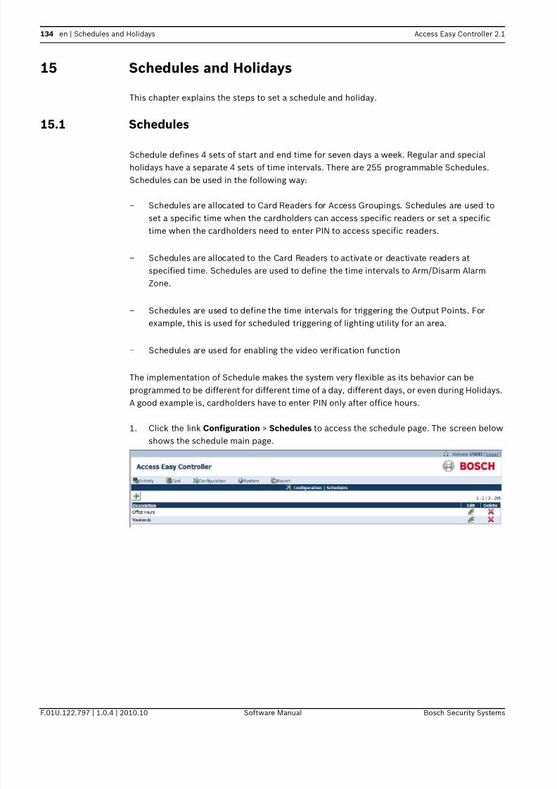
7/18/2019 User_Guide___Instruction_Book_enUS_1385855115.pdf
http://slidepdf.com/reader/full/userguideinstructionbookenus1385855115pdf 134/194
134 en | Schedules and Holidays Access Easy Controller 2.1
F.01U.122.797 | 1.0.4 | 2010.10 Software Manual Bosch Security Systems
15 Schedules and Holidays
This chapter explains the steps to set a schedule and holiday.
15.1 Schedules
Schedule defines 4 sets of start and end time for seven days a week. Regular and special
holidays have a separate 4 sets of time intervals. There are 255 programmable Schedules.
Schedules can be used in the following way:
– Schedules are allocated to Card Readers for Access Groupings. Schedules are used to
set a specific time when the cardholders can access specific readers or set a specific
time when the cardholders need to enter PIN to access specific readers.
– Schedules are allocated to the Card Readers to activate or deactivate readers at
specified time. Schedules are used to define the time intervals to Arm/Disarm Alarm
Zone.
– Schedules are used to define the time intervals for triggering the Output Points. For
example, this is used for scheduled triggering of lighting utility for an area.
– Schedules are used for enabling the video verification function
The implementation of Schedule makes the system very flexible as its behavior can be
programmed to be different for different time of a day, different days, or even during Holidays.
A good example is, cardholders have to enter PIN only after office hours.
1. Click the link Configuration > Schedules to access the schedule page. The screen below
shows the schedule main page.
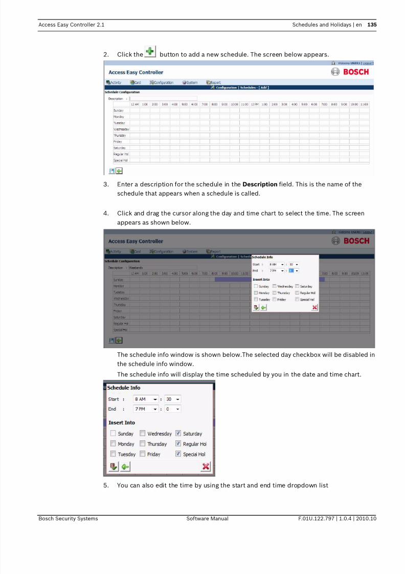
7/18/2019 User_Guide___Instruction_Book_enUS_1385855115.pdf
http://slidepdf.com/reader/full/userguideinstructionbookenus1385855115pdf 135/194
Access Easy Controller 2.1 Schedules and Holidays | en 135
Bosch Security Systems Software Manual F.01U.122.797 | 1.0.4 | 2010.10
2. Click the button to add a new schedule. The screen below appears.
3. Enter a description for the schedule in the Description field. This is the name of the
schedule that appears when a schedule is called.
4. Click and drag the cursor along the day and time chart to select the time. The screen
appears as shown below.
The schedule info window is shown below.The selected day checkbox will be disabled in
the schedule info window.
The schedule info will display the time scheduled by you in the date and time chart.
5. You can also edit the time by using the start and end time dropdown list

7/18/2019 User_Guide___Instruction_Book_enUS_1385855115.pdf
http://slidepdf.com/reader/full/userguideinstructionbookenus1385855115pdf 136/194
136 en | Schedules and Holidays Access Easy Controller 2.1
F.01U.122.797 | 1.0.4 | 2010.10 Software Manual Bosch Security Systems
6. To copy the same time setting to other days use the insert info selection checkbox.
7. Click the save button to save the settings. Click the back button to return to the
schedule page without applying the changes or click the delete button to delete the
settings and return to the schedule page.
8. After saving the settings the time of operation is copied to the selected days and a
sample schedule window is shown below for reference.
9. Click the save button to save the schedule. Click the back button to cancel the
changes and return to the schedule main page.
In the Schedule main page you can edit or delete a schedule. Click the edit button to
edit the settings of the existing schedule. The edit schedule page is same as the add schedule
page.
Click the delete button to delete an existing schedule.
15.1.1 System Behavior when using ScheduleThe diagram below provides a graphical representation of the system's behavior when a
Schedule is used on the various functions.

7/18/2019 User_Guide___Instruction_Book_enUS_1385855115.pdf
http://slidepdf.com/reader/full/userguideinstructionbookenus1385855115pdf 137/194
Access Easy Controller 2.1 Schedules and Holidays | en 137
Bosch Security Systems Software Manual F.01U.122.797 | 1.0.4 | 2010.10
Notice that all the functions toggle its state only at 1731 hrs instead of 1730 hrs. The reason is
that AEC2.1 takes 17:30:59hrs as a valid End time for 1730hrs.
15.2 Holidays
This chapter covers step by step procedure to set up Holiday parameters. Holiday parameters
are set only if the system operation behavior is different during holidays. Some samples of
how the parameters affect the system operation behavior are: -
– The controller unlocks a specific door during certain working hours of the day. However,
during a holiday, the door will remain locked the whole day.
– A cardholder is allowed access to certain areas during working hours. However during a
holiday, the cardholder is not allowed access.
Holidays set-up consist of 64 Holidays selection, of which 32 are assigned for Regular Holiday
dates and the other 32 are assigned to Special Holiday dates. There is no difference between
the operational behaviors of both types. For simplicity, you may treat the Special Holiday set
up for use during the eve of a holiday.
Each Holiday date has the feature 'Include year in processing?', if it is set to No, the system
will not consider the Year during a date check. This feature is useful if the holiday date falls on
the same date year after year e.g. New Year day and Christmas Day. This date needs to be
defined once and the holiday date is set on the same date every year. For those holiday dates
that vary from year to year the date has to be updated at the beginning of the year, and
'Include year in processing?' must be set to Yes.
You can use this feature to ease the updating of holiday dates every year by allocating the
fixed holiday dates to regular holiday and the variable holiday dates to special holidays. In this
way, you just need to update the variable holiday dates i.e. special holidays and skip the fixed

7/18/2019 User_Guide___Instruction_Book_enUS_1385855115.pdf
http://slidepdf.com/reader/full/userguideinstructionbookenus1385855115pdf 138/194
138 en | Schedules and Holidays Access Easy Controller 2.1
F.01U.122.797 | 1.0.4 | 2010.10 Software Manual Bosch Security Systems
holiday dates i.e. regular holidays at the beginning of the year.
1. Click the link Configuration > Holidays to access the holiday page. The screen below
appears.
2. In the Holiday main page select the tab regular holiday and click the button to add a
new holiday date. The screen below appears.
3. Enter a description for the holiday in the Description field
4. Click the calendar picker to select the holiday date.
5. Click the radio button No besides Include year in processing? if the holiday date is fixed,
else click Yes.
6. Click the save button to save the entries. Click the back button to cancel the entries and
return to the holiday main page
7. Repeat steps 2 to 7 for configuring special holidays also.
In the Holiday main page you can edit or delete a holiday. Click the edit button to edit
the settings of the existing holiday. The edit holiday page is same as the add holiday page.
Click the delete button to delete an existing holiday.

7/18/2019 User_Guide___Instruction_Book_enUS_1385855115.pdf
http://slidepdf.com/reader/full/userguideinstructionbookenus1385855115pdf 139/194
Access Easy Controller 2.1 Users | en 139
Bosch Security Systems Software Manual F.01U.122.797 | 1.0.4 | 2010.10
16 Users
This chapter explains the steps to define different access controls to users.
16.1 User Administration
Each user is assigned access rights to access and carry out programming of certain or all
functions of the AEC2.1.
The User administration menu item allows the System Administrator to define different access
control to users, by selecting whether a particular user can have View and/or Edit/Control
rights to programming certain functions.
The system can assign 24 users. By default, user1 is defined as the Super-user having access
to all the AEC2.1 features. The user id and password of the super user can be changed but the
function rights of the super user cannot be modified or disabled.
The default super-user can define the access rights (View and/or Edit/Control) of the
remaining 24 users, up to the level equivalent to the Super-user.
The AEC2.1 software will not display the access button of the functions for the users who do
not have the Supervisory Access Level rights login, implying that changes or settings made
cannot be saved.
16.1.1 To enter user information
1. Click the link System > User Administration to access the user details page. the screen
below shows the User Administration home page. The user administration main page
consists of two tabs namely the User and User Profile.
2. Select the User tab to add or modify User information.
3. Click the button to add a new user to the AEC2.1 system. The screen below shows
the add user page.

7/18/2019 User_Guide___Instruction_Book_enUS_1385855115.pdf
http://slidepdf.com/reader/full/userguideinstructionbookenus1385855115pdf 140/194
140 en | Users Access Easy Controller 2.1
F.01U.122.797 | 1.0.4 | 2010.10 Software Manual Bosch Security Systems
4. Enter a username in the Username field
5. Enter the password in the Password field. The password is limited to 50 alphanumerical
characters including punctuation marks.
6. Re-enter the password in the confirm field. The password entered in the Password field
and Confirm Password field must match else a error pops up indicating wrong password
entered.
7. Select whetehetuser profile dropdown list. The user profile dropdown lists the user
profiles created in the user profile page. This lists the pre defined access rights for the
user. A user can be assigned to a profile by selecting the profile from the dropdown. This
reduces the time in creating individual user access rights.
Select the option for Default Login page from the drop down list. This action will take
the user to the particular page selected by the user.
8. Select Video Access options according to the location of the camera. If the camera is at
remote location, then select Internet option else select Intranet.
9. Click the save button to save the setting. Click the back button to cancel the settings and
to return to the user main page.
In the User main page you can edit or delete a user configuration. Click the edit button
to edit the settings of the existing user. The edit user page is same as the add user page.
Click the delete button to delete an existing user configuration.
16.1.2 To select user profileRefer to the corresponding chapters to understand the various menu items before assigning
the access rights to the user.
The FTP (File Transfer) title refers to the use of the separate AEC2.1 Utility program called the
Database Converter. Refer to AEC2.1 Utility Programs Manual for more details.
User profile page consists of the option View and Edit/Control.
View
If checked, implies the user has rights to view the contents of that menu item.
Edit/Control
If checked, implies the user has the right to access and edit the setting within the menu item
NOTICE!
The username and Password are case-sensitive. For security reason, every character entered
in the Password field is represented by a dot.

7/18/2019 User_Guide___Instruction_Book_enUS_1385855115.pdf
http://slidepdf.com/reader/full/userguideinstructionbookenus1385855115pdf 141/194
Access Easy Controller 2.1 Users | en 141
Bosch Security Systems Software Manual F.01U.122.797 | 1.0.4 | 2010.10
1. Click the link System > User Administration to access the user page. In the user
administration page select the tab user profile to edit the access rights of the user. The
screen below shows the User Profile page.
2. In the user profile main page click the button to add a new profile. The screen below
shows the add user profile page.
3. Enter a description for the user profile in the Description field. This description is
presented in the user profile dropdown list in the user information page.

7/18/2019 User_Guide___Instruction_Book_enUS_1385855115.pdf
http://slidepdf.com/reader/full/userguideinstructionbookenus1385855115pdf 142/194
142 en | Users Access Easy Controller 2.1
F.01U.122.797 | 1.0.4 | 2010.10 Software Manual Bosch Security Systems
4. Select the desired checkbox for the user to have access to view and/or Edit/Control the
menu items. To de-select access rights, click the check box again.
For example in the Reports heading, you can grant access to the user to save the report
in a csv format. This option is available for the activity and audit log reports. For other
reports you can only view the report preview.
5. Click the save button to save the settings. Click the back button to cancel the
settings and return to the user profile main page.
In the User Profile main page you can edit or delete a user profile. Click the edit button
to edit the settings of the existing user profile. The edit user profile page is same as the add
user profile page.
Click the delete button to delete an existing user profile.

7/18/2019 User_Guide___Instruction_Book_enUS_1385855115.pdf
http://slidepdf.com/reader/full/userguideinstructionbookenus1385855115pdf 143/194
Access Easy Controller 2.1 Network Settings | en 143
Bosch Security Systems Software Manual F.01U.122.797 | 1.0.4 | 2010.10
17 Network SettingsThe network settings menu allows you to configure the Panel's IP, Netmask, and Gateway
Address. Each AEC2.1 comes with 2 LAN ports labeled LAN1 and LAN2. These LAN ports are
physically individual ports that have their own IP address.LAN1 is connected to the network
where the AEC2.1 is accessed by other workstations and is usually the office network and
LAN2 is used for catering further expansion.In addition, you can define three Remote PCAddresses for FTP purposes and the address of the email server. User using DB Backup will
also need to include the PC (IP Address) running the DB Backup software as one of the
remote PC.
17.1 Network
Following sections describe the configuration and settings for Network:
17.1.1 Network Setting1. Click the link System > Network Setting and in the network settings main page click the
tab Network to access the Network Setting page. The network page is the default page of
network settings menu. The screen below appears.
2. Enter the Panel IP Address in the Panel's IP field.
3. Repeat the above step for the Panel's Netmask and Gateway.
4. Enter the primary and secondary DNS if you are using a DNS server
5. Click the save button to save the settings.NOTICE!
In order for the new IP Address to take effect, the Controller has to be rebooted.
NOTICE!
Always backup the Database before rebooting.

7/18/2019 User_Guide___Instruction_Book_enUS_1385855115.pdf
http://slidepdf.com/reader/full/userguideinstructionbookenus1385855115pdf 144/194
144 en | Network Settings Access Easy Controller 2.1
F.01U.122.797 | 1.0.4 | 2010.10 Software Manual Bosch Security Systems
17.1.2 Remote PC AddressesThe remote PC addresses window in the network settings page allows you to enter the IP
address of three dedicated personal computer's IP Address to download parameters using the
utility programs, DB backup, Report Generator and DB administrator.
To edit Remote PC Addresses
1. Enter the IP Address's of the remote PC in the IP address field
2. Enter the PC name as a complete word, with no spacing in the hostname field.
3. Click the save button to save the settings. The screen below shows an example of
the network settings page.
17.2 Email Server Setup Information
This section allows you to define the IP address of the Outgoing Mail (SMTP) server, the SMTP
port to use and the AEC2.1 Email Address/Name. Click the link System > Network settings
and in the network settings main page click the Email Server tab to access the Email server
information page. The screen below shows the Email server page
NOTICE!
For usage of the utility programs, refer to the AEC2.1 Utility Programs Manual.

7/18/2019 User_Guide___Instruction_Book_enUS_1385855115.pdf
http://slidepdf.com/reader/full/userguideinstructionbookenus1385855115pdf 145/194
Access Easy Controller 2.1 Network Settings | en 145
Bosch Security Systems Software Manual F.01U.122.797 | 1.0.4 | 2010.10
The Outgoing Mail (SMTP) Server defines the server that provides your email facilities and the
AEC2.1 Email Address/Name in the reply address for emails sent by the AEC2.1 that is, the
name address that is to appear in the 'sent to' field of the dispatched email. Check the Email
Service Logon Information icon for authentication. The user can key in the user name and
password of upto 16 characters.
17.2.1 To Configure the Email Server Setup Information1. Enter the Outgoing Mail Server IP address in the Outgoing Mail (SMTP) Server field.
2. The default number (25) is the commonly used port number for the Outgoing Mail
(SMTP) Server, unless your configuration is different, we suggest you skip this field.
3. Enter the AEC2.1 Address/Name as a complete word, with no spacing in between. You
can use the underscore ( _ ) to denote spacing. The Address/Name specified in this field
will be used together with the Domain name to form the email address of the AEC2.1.
Referring to the diagram and with the Domain name "bosch.com.sg", the email address of
AEC2.1 will be [email protected]
4. Click the save button to save the settings.
17.3 Dial In IP Setup Information
This section allows you to configure the Dial In IP that is required for PPP protocol. In order to
have remote access ability using a modem for connection, a temporary IP address has to be
issued to the incoming connection. When you dial in from home, using your PC and a modem,
the AEC2.1's modem will answer the incoming call and negotiate with the remote modem for
a suitable connection protocol and speed. If the process is successful, a temporary IP is
issued to the remote modem and the connection is established. By default, this Dial in IP
address is set at 10.1.1.2. It work's fine on most network setup, change the address if youencounter connection problem.
To change this setting, click the link System > Network settings and in the network settings
page click the Dial In tab to access the Dial In Setting page.The screen below shows the Dial
In settings page.
17.3.1 To edit the Dial In IP Settings Information1. Enter the default IP in the Dial In IP field.

7/18/2019 User_Guide___Instruction_Book_enUS_1385855115.pdf
http://slidepdf.com/reader/full/userguideinstructionbookenus1385855115pdf 146/194
146 en | Network Settings Access Easy Controller 2.1
F.01U.122.797 | 1.0.4 | 2010.10 Software Manual Bosch Security Systems
2. Enter a Username and Password for the user to access the AEC2.1 through a dial In
process
3. Select a number from the dropdown for the number of illegal attempts the user can have
before successfully logging in the system
4. Select a time from the Lockout duration dropdown. This time is the time duration set
between illegal attempts. The time range is between 1 to 255 minutes.
5. Click the save button to save the settings.
17.4 SMS Server Settings Information
The SMS server menu allows you to define the IP address of the AEC2.1 that has a GSM
adapter attached to its serial com acting as the SMS server. To briefly understand how the
SMS feature works, we need to understand how the system must be configured.
The following diagram shows more than one AEC2.1 in the network. These controllers work
stand-alone but share a common GSM adapter, which is attached to a dedicated AEC2.1 serial
com port.
The AEC2.1 has a GSM adapter connected to its serial com port and acts as a SMS Server to
help relay the other AEC2.1 messages to the Service Provider.
Whenever, there are any SMS messages that need to be sent, the respective AEC2.1 will send
the SMS messages over to the AEC2.1 SMS Server and the SMS Server will send via the GSMadapter to the Service Provider. These controllers are defined as the SMS Client. Hence, there
is a need to control the IP Address that is allowed to send SMS; this is to prevent
unauthorized personnel sending SMS via your AEC2.1.
17.4.1 To Configure Access Easy Controller 2.1 as a SMS Server
NOTICE!
US Robotics 56K modems are tested with the AEC2.1 for dial up functionality. For other
brands, refer the hardware manual for protocol requirement.
NOTICE!
AEC2.1 only supports WAVECOM GSM modems. Please ensure that GSM adapter baud rate is
configured at 115200bps, 8bit data, 1 stop bit and no parity settings.

7/18/2019 User_Guide___Instruction_Book_enUS_1385855115.pdf
http://slidepdf.com/reader/full/userguideinstructionbookenus1385855115pdf 147/194
Access Easy Controller 2.1 Network Settings | en 147
Bosch Security Systems Software Manual F.01U.122.797 | 1.0.4 | 2010.10
Click the link System > Network Settings and in the network setting page select the tab SMS
Server to configure the SMS server setting of the AEC2.1. The screen below shows the SMS
server settings page. By default, the SMS Server IP address is blank as shown below.
If this controller is attached to a GSM adapter, you will need to configure the IP address of
other AEC2.1 that will send SMS message through it.
1. Since this is an SMS Server, select the radio button Yes besides GSM Connected?. The
SMS Server Setting page is shown below:
2. There are up to 10 Remote Controller addresses that you can configure. These addresses
are the IP Address of those AEC2.1’s that send SMS messages via the SMS Server. Be
sure to include the IP address of the AEC 2.1 that is acting as the SMS server or else it
will not be able to send SMS while the rest is able to.
3. Click the save button to save the settings.
17.5 AEMC SettingsAccess Easy series come with an Access Easy Master Controller. The master controller
enables you to connect to up to 20 AEC2.1 through a hub. This will greatly increase the
capacity of the whole system. To differentiate between a stand-alone controller and one that
is connected to a master controller, they will be referred as AEC2.1 and Access Easy Master 2
respectively.

7/18/2019 User_Guide___Instruction_Book_enUS_1385855115.pdf
http://slidepdf.com/reader/full/userguideinstructionbookenus1385855115pdf 148/194
148 en | Network Settings Access Easy Controller 2.1
F.01U.122.797 | 1.0.4 | 2010.10 Software Manual Bosch Security Systems
17.6 LAN Converter
The LAN Converter tab will ask for the IP address of the LAN Converter. Connecting through
the LAN converter, the system can be upgraded to 16 interface boards. The default IP address
is 192.168.2.42. If the user is connecting it to the CPU LAN 2 then enter 192.168.2.X, where X
can be any number except 41 since 192.168.2.41 is the reserved IP address for LAN 2.
The LAN converter support requires AEC2.1 firmware upgrade version 2.1.6.0 or later. Please
check our online AEC software upgrade at http://www.boschsecurity.us/en-us/aec .

7/18/2019 User_Guide___Instruction_Book_enUS_1385855115.pdf
http://slidepdf.com/reader/full/userguideinstructionbookenus1385855115pdf 149/194
Access Easy Controller 2.1 System Settings | en 149
Bosch Security Systems Software Manual F.01U.122.797 | 1.0.4 | 2010.10
18 System Settings
This chapter explains the steps to synchronize the system time to the PC time or server time.
18.1 Date and Time
Following sections describe the settings and activation of Date and Time:
18.1.1 Set Date & Time
The AEC2.1 software allows you to set the Date and Time of the real-time clock within the
controller. For countries that practice Daylight Saving Time, the feature is included. Time
setting is in the 24-hour format.
An additional function is implemented to allow you to maintain date and time synchronization
with a timeserver. With synchronization on all of AEC2.1, you can ensure that the events that
happen in sequence on different controller can be analyzed correctly. AEC2.1 only support
NTP Time server, it will performs synchronization with the NTP Time server every night at 3am.
18.1.2 To activate Date & Time SettingClick the link System > Date and Time and in the date and time main page select the tab
Date/Time to access the date and time setting of the AEC2.1 The screen below appears.
18.1.3 To set the Date & Time1. The Date/Time main page shows the Panel Date/Time and the PC Date/Time. Click the
synchronize button to synchronize the Panel time with the PC time.
2. Select the appropriate Time Zone corresponding to the country from Choose Time Zone
dropdown.

7/18/2019 User_Guide___Instruction_Book_enUS_1385855115.pdf
http://slidepdf.com/reader/full/userguideinstructionbookenus1385855115pdf 150/194
150 en | System Settings Access Easy Controller 2.1
F.01U.122.797 | 1.0.4 | 2010.10 Software Manual Bosch Security Systems
3. Select the date format from the date format dropdown. Click the save button to
save the settings.
18.2 NTP Settings (Network Time Protocol Settings)
Following sections describe the synchronisation of Date and Time:
18.2.1 To set the Time Synchronization
1. Click the link System > Date and Time and in the date and time settings page select the
tab NTP to access the time synchronization settings page. The screen below shows the
NTP settings page.
2. Select the checkbox besides Enable NTP Time server for synchronization and key in the
IP address of the Timeserver PC in the Time Server IP address/name. Click the
synchronize button to synchronize the AEC2.1 system time with the server time.
3. Select the checkbox besides Disable synchronization if time difference between AEC
and Time Server is >15 minutes if you do not want the AEC 2.1 to synchronize its time
with the server even if the difference is more than 15 minutes. This is useful as it
prevents the AEC2.1 from synchronizing the wrong time with the Time server that is not
accurate or is not in time with the timezone.
NOTICE!
If your country is not listed, please select an alternative country that uses the same Time Zone.
NOTICE!
Refer to the section on Setting up a Timeserver PC. Time Server Address/DNS input is the IP
address of the PC being configured as a time server PC. AEC2.1 is only able to synchronize
with a NTP time server and will sync at 3 am daily automatically. Auto Time synchronization at
3 am is only logged at transaction, however if you manually synchronize with the timer server,
audit log will be logged.
7/18/2019 User_Guide___Instruction_Book_enUS_1385855115.pdf
http://slidepdf.com/reader/full/userguideinstructionbookenus1385855115pdf 151/194
Access Easy Controller 2.1 System Settings | en 151
Bosch Security Systems Software Manual F.01U.122.797 | 1.0.4 | 2010.10
Synchronizing date & time with a internet Time Server
Access Easy Controller 2.1 is not able to synchronize with an internet Time Server if it is
behind a firewall or proxy server. If it is outside the firewall or in a DMZ, you can enter the IP
address of the Time Server in the Time Server Address/DNS input. Do not enter the domain
name of the Time Server (e.g. Time.windows.gov) in this input. AEC2.1 will not be able to
resolve the name to an IP address.
Synchronizing date & time with an intranet Time Server
It is recommended that AEC2.1 should synchronize its date & time to an intranet (internal)
Time Server. Most of the office has an internal Time Server, this Time Server will synchronize
its date & time with an internet (external) Time Server, while all other PCs in the office
synchronize with this intranet Time Server.
If the office does not have an intranet Time Server, you can setup any existing PC on the
network as a Time Server, hence, the AEC2.1 can synchronize its date and time with this PC.
There are numerous freeware available that you could install in this PC to synchronize its date
and time with an external Time Server.

7/18/2019 User_Guide___Instruction_Book_enUS_1385855115.pdf
http://slidepdf.com/reader/full/userguideinstructionbookenus1385855115pdf 152/194
152 en | Email/SMS Configuration Access Easy Controller 2.1
F.01U.122.797 | 1.0.4 | 2010.10 Software Manual Bosch Security Systems
19 Email/SMS ConfigurationThis function allows you to configure the AEC2.1 to send out messages or Lateness Report
using Simple Mail Transfer Protocol (SMTP) to email addresses. A total of eight groups and
eight messages field are available for configuration. Each group has two "Send To" and two
"Carbon Copy (Cc)" email addresses.
In order for the feature to work, you have to configure the Devices, Cardholders, and Events in
an AND operation. To exclude/disable an item(s) from the operation, the option Selected Only
or Omit Only must be used with nothing selected. While for the Lateness Report, the feature
is disable if no selection is made on any of the day of week (DOW).
19.1 Email Configuration
Click the link Configuration > E-mail/SMS setting in the E-mail/SMS main page select the tab
E-mail. In the Email page click the edit button besides any Undefined Email. The screen below
shows the Email configuration page.
This web page allows you to configure the email addresses of the recipients. The AEC2.1 will
ignore any configurations made for the group if there is no email address in the To field even if
there is an email address in the Cc field. Each To and Cc must contain one email address,
multiple email addresses are not allowed address, hence, will not send out the mail to the
recipients.
19.1.1 To edit the Email Configuration1. Enter a Description for the mail in the Description field. This description is the subject of
the mail.
2. In the Email Address Setting window enter the email address in the appropriate field.
3. In the Criteria settings window select a criteria from the Criteria Selection dropdown.
4. Select a message from the Message dropdown. The messages are configured in the
message tab of the Email/SMS settings page.
5. Click the save button to save the email as a draft copy. Click the back button
to cancel the settings and return to the main Email/SMS settings page. Click the send
button to send the Email to the recipients in the email address window.

7/18/2019 User_Guide___Instruction_Book_enUS_1385855115.pdf
http://slidepdf.com/reader/full/userguideinstructionbookenus1385855115pdf 153/194
Access Easy Controller 2.1 Email/SMS Configuration | en 153
Bosch Security Systems Software Manual F.01U.122.797 | 1.0.4 | 2010.10
19.1.2 To send the Email
1. Click the send button to send the email
2. A successful test message will appear
3. Click the OK button to acknowledge the message.
4. If you are unable to send out the email, please check your Email Server Settings again.
In the Email main page you can edit or delete a Email setting. Click the edit button to
edit the settings of the existing Email. The edit Email settings page is same as the add Email
settings page.
Click the delete button to delete an existing Email setting.
19.2 SMS ConfigurationClick the link Configuration > Email/SMS setting in the email/SMS main page select the tab
SMS. In the SMS main page click the edit button besides any Undefined SMS. The screen
below shows the SMS configuration page.
1. Enter a description in the Description field.
2. In the Mobile Device Setting window enter the mobile numbers to which the SMS has to
be sent. The system can configure up to four mobile devices.
3. In the Criteria settings window select a criteria from the Criteria Selection dropdown.
4. Select a message from the Message dropdown. The messages are configured in the
message tab of the Email/SMS settings page.
5. Click the save button to save the SMS as a draft copy. Click the back button to
cancel the settings and return to the main Email/SMS settings page. Click the send
button to send the SMS to the mobile devices in the Mobile device settings window.

7/18/2019 User_Guide___Instruction_Book_enUS_1385855115.pdf
http://slidepdf.com/reader/full/userguideinstructionbookenus1385855115pdf 154/194
154 en | Email/SMS Configuration Access Easy Controller 2.1
F.01U.122.797 | 1.0.4 | 2010.10 Software Manual Bosch Security Systems
19.2.1 To send the Email
1. Click the send button to send the SMS
2. A successful test message will appear
3. Click the OK button to acknowledge the message.
In the SMS main page you can edit or delete a SMS. Click the edit button to edit the
settings of the existing SMS. The edit SMS page is same as the add SMS page.
Click the delete button to delete an existing SMS.
19.3 Message Configuration
The Message field constitutes the 'body text' while the Event is to appear in the 'subject' field
of the dispatched email.
19.3.1 To edit the Message field1. Click the link Configuration > Email/SMS Settings and in the Email/SMS settings page
select the Message tab. In the message main page click the edit button besides any
Undefined Message. The screen below shows the message tab.
2. Enter a description in the Description field
3. Enter the new message in the text box provided, limiting to 127 characters including
punctuation.
4. Click the save button to save the message. This message is now available in the
message dropdown list in the Email settings page. Click the back button to cancelthe settings and return to the main page.
In the Message main page you can edit or delete a message. Click the edit button to edit
the settings of the existing message. The edit message page is same as the add message page.
Click the delete button to delete an existing message.

7/18/2019 User_Guide___Instruction_Book_enUS_1385855115.pdf
http://slidepdf.com/reader/full/userguideinstructionbookenus1385855115pdf 155/194
Access Easy Controller 2.1 Advance Settings | en 155
Bosch Security Systems Software Manual F.01U.122.797 | 1.0.4 | 2010.10
20 Advance Settings
This chapter will guide you through some of the advance features available in AEC2.1.
20.1 System Maintenance
Following sections describe the various maintanence activities for the panel:
20.1.1 To activate Reboot Panel
Since the AEC2.1's software is residing within its hardware. The Reboot Panel menu item
allows you to reboot the controller after upgrading to the system software or in order to allow
changes made to take effect, especially changes made to Network Setting, such as Panel's IP
Address.
1. Click the link System > Advance Settings and in the advance settings main page select
the System maintenance tab to reboot the panel.The screen below shows the Advance
Settings > System Maintenance page.
2. In the maintenance options window click the reboot button to reboot the panel
3. The message box appears for confirmation. Click the OK button to proceed.
4. It takes about two minutes for the process to complete (see NOTICE).
Once the AEC2.1 is up and running again, enter the AEC2.1 URL Address and proceed with the
Login.
20.1.2 To Shutdown Panel
The Shutdown Panel function allows you to do a proper shutdown of the controller hardware.
This is usually done when controller hardware requires a hardware upgrade or maintenance.
CAUTION!
During a Reboot Panel function, all settings and parameters are taken from the flash
memories. In such a case, it is important that the Database Backup function is carried out
before proceeding to reboot the AEC2.1.
NOTICE!
During the rebooting process, the AEC2.1 disconnects itself from the computer and the web
page on the computer screen might show an error message or be completely blank. You
should close and re-launch the web browser program. Login to AEC2.1 again after the process
is completed.

7/18/2019 User_Guide___Instruction_Book_enUS_1385855115.pdf
http://slidepdf.com/reader/full/userguideinstructionbookenus1385855115pdf 156/194

7/18/2019 User_Guide___Instruction_Book_enUS_1385855115.pdf
http://slidepdf.com/reader/full/userguideinstructionbookenus1385855115pdf 157/194
Access Easy Controller 2.1 Advance Settings | en 157
Bosch Security Systems Software Manual F.01U.122.797 | 1.0.4 | 2010.10
2. Click the upload button to upload the file.
3. A message box appears for confirmation. Click the OK button to proceed. Once the
process is completed without error, the confirmation message will appear.
4. Reboot the AEC2.1.
5. Click on the browser link AEC2.1 Update to download the latest patch from the Bosch
intranet.
20.2.2 To Update Panel SoftwareDue to the constant development of the software, the software is designed to allow you to
upgrade to the newest version by uploading a file. To differentiate between uploading settings
and configurations, and updating the panel software, the names of the files to upload are
fixed. For uploading settings and configurations to the panel, you will upload a db_tar file. To
update the panel software, a file named aec_sys will be uploaded.
20.3 Database Backup
The database menu allows you to choose two options, Backup Database to the Flash Memory
or to the Desktop. Backup Database To Flash Memory allows you to overwrite the database in
the flash memory with the current parameters in the Dynamic Random Access Memory
(DRAM). The flash memory acts as a permanent storage just like the computer's hard disk
drive. Every time a Reboot is initiated, the AEC2.1 software will access the flash memory for
parameter setting, card database …etc. You are given the option to allow the AEC2.1 to carry
out an automatic backup at specific time of the day or to do it manually.
NOTICE!
– Upload db_tar file for uploading settings and configurations
– Upload aec_sys file for updating the panel software

7/18/2019 User_Guide___Instruction_Book_enUS_1385855115.pdf
http://slidepdf.com/reader/full/userguideinstructionbookenus1385855115pdf 158/194
158 en | Advance Settings Access Easy Controller 2.1
F.01U.122.797 | 1.0.4 | 2010.10 Software Manual Bosch Security Systems
The backup database contains the entire database of the AEC2.1 inclusive of activities and
logs. Backup Database To Desktop provides downloading of information which relates to the
setting up of AEC2.1, for example: - Schedules details, Card Readers parameters…etc. It also
allows you to download the history of the Activity and Attendance in Comma Separated
Variable (CSV) format.
With the downloading, you can save the parameters (in encrypted zipped file) and the
transactions as a backup on your computer hard disk or other external storage media, or
floppy diskette.
20.3.1 To activate Database BackupClick the link System > Advance Settings and in the advance settings main page select the
Database Backup tab to access the Database backup page. The screen below shows the
database backup page.
20.3.2 To define Daily Backup Schedule1. Select the appropriate hour and minute from the dropdown list besides Daily backup
schedule.
2. Click the save button to save the backup settings
If you wish to disable this feature, select the "blank" for both Hour and Minute field as
illustrated above.
20.3.3 To Backup System Database To DesktopThis process involves two stages, when activated; the software will collect all parameter
settings and zipped them up in an encrypted file called db_tar.gz. This encrypted file is only
recognizable by the AEC2.1 thus providing security of its contents.
WARNING!
This function requires at least 2-3 minutes to complete the download. During this period,
please do not switch off power to the AEC2.1 or close your Web Browser application. You
MUST wait till the downloading page appears before you could proceed to other page or close
the Web Browser application. If this step is not followed, the backup operation will not be
completed.
WARNING!
This function required at least 2-3 minutes to complete. During this period, please do not
switch off power to either the computer or the AEC2.1.

7/18/2019 User_Guide___Instruction_Book_enUS_1385855115.pdf
http://slidepdf.com/reader/full/userguideinstructionbookenus1385855115pdf 159/194
Access Easy Controller 2.1 Advance Settings | en 159
Bosch Security Systems Software Manual F.01U.122.797 | 1.0.4 | 2010.10
1. Click the System Database Backup button and the system will start backing up the
System Database into the encrypted file. Once that is done, the Save As dialog box
appears.
The function of the Save As dialog box is the same as any Windows software application,
so it is very easy to select the destination location of the zip file.
2. Click the save button to proceed.
20.4 Customer Logo
1. Click the link System > Advance Settings and in the Advance Settings page select the
Customer Logo tab. The screen below shows the customer logo page.
2. Click the browse button besides the logo field to select the logo file from the system.
Click the upload button after selecting the logo.
20.5 Video SDK
This function is necessary to access the video features available in AEC2.1. A Video SDK
should be selected if you want to view the videos. If a Video SDK is not selected you will not
be able to view the video features and the transactions page will not display the surveillance,
camera monitoring and video verification function tabs.
NOTICE!
Do not change the default file name of the file. The AEC2.1 will not recognize it when you
import it back for database recovery purpose.
NOTICE!
Some of the Web Browser application needs only to click the icon and it will prompt you
immediately to save or to open the file. If that is the case choose the save option.
NOTICE!
The file to upload MUST be named "CustomerLogo.gif" with a file size of less than 10KB.

7/18/2019 User_Guide___Instruction_Book_enUS_1385855115.pdf
http://slidepdf.com/reader/full/userguideinstructionbookenus1385855115pdf 160/194
160 en | Advance Settings Access Easy Controller 2.1
F.01U.122.797 | 1.0.4 | 2010.10 Software Manual Bosch Security Systems
1. Click the link System > Advance Settings and in the advance settings page select the
Video SDK tab.
Select the latest Video SDK version and click the upload icon. Once it is updated the
message to restart the browser appears, as shown in the figure. Restart the browser to
get the latest patch.
2. The Video SDK page lists all the available Video SDK’s. In the List of Available Video
SDK’s window the BOSCH Video SDK is selected by default. If any camera is configured
then the selected Video SDK is automatically downloaded.
Note: Due to some security reasons the Video SDK may not automatically download and
install. In that case you can download using the download button in the Download
column to manually download the Video SDK from the system to the remote PC or you
can get the Video SDK from the utility CD. Contact the system administrator to install the
Video SDK in the remote PC.
3. Click the save button to save the settings
20.5.1 Upload Video SDK
The Video SDK window allows you to upload a Video SDK from the remote PC to the AEC2.1panel. The upload option is used to upload a Video SDK upgrade or insert a new SDK.
Follow the steps below to upload a Video SDK file to the AEC2.1 system.
1. Click the Browse button to browse for the Video SDK file in the PC.
2. After selecting the file, click the upload button to upload the Video SDK from the PC
to the AEC2.1 system.
NOTICE!
Atleast one Video SDK has to be selected to view the video features and the video related
software interface pages in the AEC2.1 system.

7/18/2019 User_Guide___Instruction_Book_enUS_1385855115.pdf
http://slidepdf.com/reader/full/userguideinstructionbookenus1385855115pdf 161/194
Access Easy Controller 2.1 Advance Settings | en 161
Bosch Security Systems Software Manual F.01U.122.797 | 1.0.4 | 2010.10
20.6 System - Default Settings
Following sections describe the various default settings of the system:
20.6.1 Auto Logout TimerThe auto logout timer allows you to set the timer for the AEC2.1 software to Logout
automatically if it detects no user activity. Default setting is 1 hour.
To activate Auto Logout Timer
1. Click the link System > Default Settings to access the auto logout timer settings. The
screen below appears.
2. Select the hour and minutes from the hour and minute dropdown list.
3. Click the save button to save the settings
20.6.2 PIN SettingsThe PIN setting option allows you to set the maximum PIN length. The PIN is entered in the
reader settings of the AEC2.1. Refer to Section 9.4.1 PIN Code Settings, page 82 for more
information.
To activate PIN settings
1. Click the link System > Default Settings to access the auto logout timer settings. The
screen below appears.
2. Select the number of characters from the Maximum PIN length dropdown.
NOTICE!
If a Video SDK upgrade is uploaded the Version of the Video SDK will be automatically
updated in the List of Available Video SDK’s window once the upload is successful. The
upgrade is automatically downloaded to the PC the next time you access the video pages in
the AEC2.1 software interface.
NOTICE!
This Timer setting is applicable to all menu items except Transactions.

7/18/2019 User_Guide___Instruction_Book_enUS_1385855115.pdf
http://slidepdf.com/reader/full/userguideinstructionbookenus1385855115pdf 162/194
162 en | Advance Settings Access Easy Controller 2.1
F.01U.122.797 | 1.0.4 | 2010.10 Software Manual Bosch Security Systems
3. Click the save button to save the settings

7/18/2019 User_Guide___Instruction_Book_enUS_1385855115.pdf
http://slidepdf.com/reader/full/userguideinstructionbookenus1385855115pdf 163/194
Access Easy Controller 2.1 Reports | en 163
Bosch Security Systems Software Manual F.01U.122.797 | 1.0.4 | 2010.10
21 Reports
This chapter explains the steps to generate a report based on the defined criterias and to
customize the hard copy report.
21.1 Activity
This menu allows you to select the types of activity report based on the combination of
Transaction or Card Number or Name or Department or location.
Click the link Report > Activity to access the activity report page. The screen below shows the
activity report page.
1. Select the Activity types from the list. The available activity types are All, Alarm, Valid,
Restore and Time Attendance.
2. Enter the required values in the card number and name field. Select the required values
and click the view report button to see a preview of the report. The screen below
shows an example of the All activities report.

7/18/2019 User_Guide___Instruction_Book_enUS_1385855115.pdf
http://slidepdf.com/reader/full/userguideinstructionbookenus1385855115pdf 164/194
164 en | Reports Access Easy Controller 2.1
F.01U.122.797 | 1.0.4 | 2010.10 Software Manual Bosch Security Systems
3. Click save as CSV or XLS file to save the report in a CSV or XSL format in the PC or click
the back button to return to report > activity page.
Note: The values entered in the fields work on AND condition.
21.1.1 To format report based on Card Number1. Select the Activity from the activities dropdown list.
2. Enter the exact Card Number in the Card Number field.
3. Click the search button. If the card number is not in the database, you will be
prompted by an error message.
4. Select the appropriate Department and location from the Department and Location
dropdown list. If you want to generate report for all locations, select All Locations.
5. Click the view report button to see a preview of the report. Click save as CSV or XLS
button to save the report in a CSV format in the PC or click the back button to
return to report > activity page.
21.1.2 To format report based on Name
1. Enter a character, a portion, or the full name in the name field. Click the search
button to search the database for the entered value. If a match is found that satisfies the
entry, a window will appear with the Names.
2. From the search result window, select the desired name. The selected name appears in
the Name field.
3. Select the appropriate department and location from the Department and Location
dropdown list. If you want to generate report for all location, select All Locations.
4. Click the view report button to see a preview of the report. Click save as CSV or
XLS file to save the report in a CSV or XLS format in the PC or click the back button
to return to report > activity page.
21.1.3 To format report based on Department1. Select the appropriate Department from the Department dropdown list
2. Select the appropriate location from the location dropdown list. If you want to generate
report for all locations, select All Locations.

7/18/2019 User_Guide___Instruction_Book_enUS_1385855115.pdf
http://slidepdf.com/reader/full/userguideinstructionbookenus1385855115pdf 165/194
Access Easy Controller 2.1 Reports | en 165
Bosch Security Systems Software Manual F.01U.122.797 | 1.0.4 | 2010.10
3. Click the view report button to see a preview of the report. Click save as CSV or
XSL file to save the report in a CSV format or XLS format in the PC or click the back
button to return to report > activity page.
21.1.4 To format report based on Location1. Select the appropriate Location from the list.
2. Select the appropriate location from the location dropdown list. If you want to generate
report for all readers, select All Locations.
3. Click the view report button to see a preview of the report. Click save as CSV or
XSL file to save the report in a CSV format or XSL format in the PC or click the back
button to return to report > activity page.
21.1.5 To format report based on Date/Time You can select the range of dates to view the activities in that date range. This would cut
down the time on scrolling through the list of activities if you know the date when the
activities have taken place.
21.2 APB
The APB Zones report allows you to know which cardholder is in the APB Zone at the time of
the preview. Should there be a need to Reset APB for a particular cardholder, you can use this
report to verify that the cardholder has actually violated the APB and not due to other
condition such as an Expired Card Number.
21.2.1 To generate APB Zones ReportThis report shows the list of cardholders still in the APB zones. When a cardholder enters an
APB zone, by opening a door from an APB entry reader, the cardholder will be registered in
the system as present in the APB zone governed by the APB entry reader. Similarly, when the
cardholder exits from an APB zone, by opening a door from an APB exit reader, the cardholder
will be de-registered in the system as present in the APB zone governed by the APB entry
reader.
1. Click the link Report > Activity and in the activity main page select the APB tab to access
the APB report page. The screen below shows the APB report page.
2. Select the desired Zone from the APB zone dropdown list.

7/18/2019 User_Guide___Instruction_Book_enUS_1385855115.pdf
http://slidepdf.com/reader/full/userguideinstructionbookenus1385855115pdf 166/194
166 en | Reports Access Easy Controller 2.1
F.01U.122.797 | 1.0.4 | 2010.10 Software Manual Bosch Security Systems
3. Select the required values and click the view report button to see a preview of the
report. Click save as CSV or XSL file to save the report in a CSV or XSL format in the PC
or click the back button to return to report > APB page.
21.3 Card1. Click the link Report > Card and in the card main page select the tab card to print a
report based on the cardholders. The screen below shows the card report page.
2. Enter the desired values in the appropriate fields.
3. Click the view report button to see a preview of the report. The screen below shows
the report for the search criteria based on name Maria.
4. Click the back button to return to report > card page.

7/18/2019 User_Guide___Instruction_Book_enUS_1385855115.pdf
http://slidepdf.com/reader/full/userguideinstructionbookenus1385855115pdf 167/194
Access Easy Controller 2.1 Reports | en 167
Bosch Security Systems Software Manual F.01U.122.797 | 1.0.4 | 2010.10
21.4 Access Group
Click the link Report > Card and in the card main page select the tab Access Group to print a
report based on the access groups. The screen below shows the access group page.
21.4.1 To generate an Access Groups report1. Select the desired access group from the access group dropdown list.
2. Click the view report button to see a preview of the report. Click the back
button to return to report > access groups page.
21.5 Reader
Following are the steps to generate a Card Reader Report:
21.5.1 To generate a Card Reader Report1. Click the link Report > Device and in the device main page select the reader tab to
access the Reader report settings. The screen below appears.
2. Select the desired Reader from the Reader Description dropdown list. Click the search
button to search the reader entered in the Reader Description field.
3. Click the view report button to see a preview of the report. Click the backbutton to return to report > reader page.
21.6 Input
Following are the steps to generate an Input Point Report:
21.6.1 To generate an Input Point Report1. Click the link Report > Device and in the device main page select the Input tab to access
the Input report settings. The screen below appears.
NOTICE!
Only Access Groups that are defined will be shown.

7/18/2019 User_Guide___Instruction_Book_enUS_1385855115.pdf
http://slidepdf.com/reader/full/userguideinstructionbookenus1385855115pdf 168/194
168 en | Reports Access Easy Controller 2.1
F.01U.122.797 | 1.0.4 | 2010.10 Software Manual Bosch Security Systems
2. Select the desired Input point from the Input Description dropdown list. Click the search
button to search the Input Point entered in the Input Description field.
3. Click the view report button to see a preview of the report. Click the back
button to return to report > input page.
21.7 Output
Following are the steps to generate an Output Point Report:
21.7.1 To generate an Output Point Report1. Click the link Report > Device and in the device main page select the Output tab to
access the Output report settings. The screen below appears.
2. Select the desired output point from the Output dropdown list. Click the search button
to search the Output Point entered in the Output field.
3. Click the view report button to see a preview of the report. Click the back
button to return to report > output page.
21.8 Advance I/O
Following are the steps to generate an I/O function Block Report:
21.8.1 To generate an I/O function Block Report1. Click the link Report > Device and in the device main page select the Advance I/O tab to
access the Advance I/O report settings. The screen below appears.
2. Select the desired I/O function block from the Advance I/O dropdown list. Click the
search button to search the I/O function block entered in the Advance I/O field.

7/18/2019 User_Guide___Instruction_Book_enUS_1385855115.pdf
http://slidepdf.com/reader/full/userguideinstructionbookenus1385855115pdf 169/194
Access Easy Controller 2.1 Reports | en 169
Bosch Security Systems Software Manual F.01U.122.797 | 1.0.4 | 2010.10
3. Click the view report button to see a preview of the report. Click the back
button to return to report > advance I/O page.
21.9 Camera
Following are the steps to generare a Report based on Camera:
21.9.1 To generate a Report based on Camera1. Click the link Report > Device and in the device main page select the Camera tab to
access the Camera report settings. The screen below appears.
2. Select the desired Camera from the Camera Description dropdown list. Click the search
button to search the Camera entered in the Camera Description field.
3. Click the view report button to see a preview of the report. Click the back
button to return to report > camera page.
21.10 Schedule
Following are the steps to generate a Schedule report:
21.10.1 To generate a Schedule Report1. Click the link Report > Configuration and in the configuration main page select the
Schedule tab to access the Schedule report settings. The screen below appears.
2. Select the desired Schedule from the Schedule Description dropdown list. Click the
search button to search the Schedule entered in the Schedule Description field.
3. Click the view report button to see a preview of the report. Click the back
button to return to report > schedule page.
21.11 Regular Holiday
Following are the steps to generate a Regular Holiday report:

7/18/2019 User_Guide___Instruction_Book_enUS_1385855115.pdf
http://slidepdf.com/reader/full/userguideinstructionbookenus1385855115pdf 170/194
170 en | Reports Access Easy Controller 2.1
F.01U.122.797 | 1.0.4 | 2010.10 Software Manual Bosch Security Systems
21.11.1 To generate a Regular Holiday Report1. Click the link Report > Configuration and in the configuration main page select the
Regular Holiday tab to access the Regular Holiday report settings. The screen below
appears.
2. Select the desired regular holiday from the Regular Holiday Description dropdown list.
Click the search button to search the Regular Holiday entered in the Regular Holiday
Description field.
3. Click the view report button to see a preview of the report. Click the back
button to return to report > regular holiday page.
21.12 Special Holiday
Following are the steps to generate a Special Holiday Report:
21.12.1 To generate a Special Holiday Report1. Click the link Report > Configuration and in the configuration main page select the
Special Holiday tab to access the Special Holiday report settings. The screen below
appears.
2. Select the desired regular holiday from the Special Holiday Description dropdown list.
Click the search button to search the Regular Holiday entered in the Special Holiday
Description field.
3. Click the view report button to see a preview of the report. Click the back
button to return to report > special holiday page.
21.13 Audit Log
User log tracks the Users operation on the AEC2.1, and logs all the action performed by the
user, such as manual on/off any output, change the settings for a Cardholder, set the date and
time, etc.
To View the User Log
1. Click the link Report > Audit Log to access the user log report settings. The screen below
appears

7/18/2019 User_Guide___Instruction_Book_enUS_1385855115.pdf
http://slidepdf.com/reader/full/userguideinstructionbookenus1385855115pdf 171/194
Access Easy Controller 2.1 Reports | en 171
Bosch Security Systems Software Manual F.01U.122.797 | 1.0.4 | 2010.10
2. Choose the From date and To date, from the Calendar picker.
3. Select the User Name from the Name dropdown list. If a particular User has been
selected, the report will only show the operation of that User. If All Names is selected,
the result will show report containing all the action performed by all users on the system.
4. Click the view report button to see a preview of the report. Click save as CSV or XSL
file to save the report in a CSV or XSL format in the PC. Click the back button to
return to report > audit log page.
21.14 View .CSV file in Excel
In MS Excel you can only view the database details and not edit them. Follow the steps below
to view the .CSV file.
Method 1
1. Rename the Card.csv file to Card.bat. Launch MS Excel and click on File > Open. Selectthe Card.bat file from the saved location. The below window appears.
2. Select Delimited from the Original Data Type option and Unicode (UTF-8) from the File
Origin dropdown. Click the Next button to complete the Text Import Wizard.
Method 2

7/18/2019 User_Guide___Instruction_Book_enUS_1385855115.pdf
http://slidepdf.com/reader/full/userguideinstructionbookenus1385855115pdf 172/194
172 en | Reports Access Easy Controller 2.1
F.01U.122.797 | 1.0.4 | 2010.10 Software Manual Bosch Security Systems
1. Open Notepad. Click on File > Open. Select the .CSV file from the local hard disk or an
external drive and click the Open button.
2. Click on File > Save As, select Unicode from the Encoding dropdown as shown below.
3. Click the save button to save the file. Close the file.
4. Launch Excel and click on File > Open. Select the Unicode Card.csv (the above saved
file) file from the saved location. The below window appears
5. Select Delimited from the Original Data Type option. Click the Next button to complete
the Text Import Wizard.
21.15 Report - Default Settings
The report menu consists of the default settings submenu. In the default settings you can edit
the report header and sub headers. The screen below shows the default settings screen.

7/18/2019 User_Guide___Instruction_Book_enUS_1385855115.pdf
http://slidepdf.com/reader/full/userguideinstructionbookenus1385855115pdf 173/194
Access Easy Controller 2.1 Reports | en 173
Bosch Security Systems Software Manual F.01U.122.797 | 1.0.4 | 2010.10
21.15.1 To edit the report settings1. Type the report header in the Report Header field. For example you can type in the
company name as the Report header.
2. Type the company address in Sub header 1 and Sub header 2 fields.
3. Click the save to save the settings.

7/18/2019 User_Guide___Instruction_Book_enUS_1385855115.pdf
http://slidepdf.com/reader/full/userguideinstructionbookenus1385855115pdf 174/194
174 en | Resetting to Factory Default Access Easy Controller 2.1
F.01U.122.797 | 1.0.4 | 2010.10 Software Manual Bosch Security Systems
22 Resetting to Factory DefaultOn the first 4-Reader board of AEC2.1 system, JP2 is used to reset the panel to factory default
setting. Refer to the Hardware Manual for more information.
When the jumpers on the left of JP2 (vertically), is shorted with a jumper link the system
provides the option to retain the current settings and configuration or clear all the settings
and configuration.
When the jumpers are shorted the screen below appears.
Click the Yes button to reset the AEC2.1 back to the factory default settings. This process will
clear all the settings and configurations set, except for the IP address. Information like Card
numbers and Advance IO settings will also be erased.
Click the No button to reboot the panel without changing the settings and configurations.
After setting the jumper link the system will reboot. Upon system reboot, enter the AEC2.1
URL address in the address field of a web browser.
To reset IPaddress
Reset to factorydefault
JP2
WARNING!
– All information, settings and configurations will be erased. Users are advised to do a
system backup before proceeding. (IP Address will not be reset with this function)

7/18/2019 User_Guide___Instruction_Book_enUS_1385855115.pdf
http://slidepdf.com/reader/full/userguideinstructionbookenus1385855115pdf 175/194
Access Easy Controller 2.1 Resetting to Factory Default | en 175
Bosch Security Systems Software Manual F.01U.122.797 | 1.0.4 | 2010.10
22.1 Resetting IP Address to Default IP Address
The jumpers on the right of JP2 (vertically), when shorted with a jumper link, will reset the
panel’s IP address back to AEC2.1 default IP address (i.e 192.168.0.41). Note that this will
only reset the IP Address back to default. No information, settings and configurations will be
altered. A reboot will be required for changes to take effect. Upon completion of rebooting,
you will be able to log onto the login screen with the default IP Address.
NOTICE!
These two functions are independent of each other and can be carried out independently or
simultaneously.
– Shorting the jumper on the left and rebooting the system will cause the panel to be reset
to factory default settings, keeping the IP Address unchanged.
– Shorting the jumper on the right and rebooting the system will cause the panel to reset
ONLY the IP Address to default IP Address.
– Shorting both will reset both the, configurations and settings, and IP Address.

7/18/2019 User_Guide___Instruction_Book_enUS_1385855115.pdf
http://slidepdf.com/reader/full/userguideinstructionbookenus1385855115pdf 176/194
176 en | APPENDIX A Access Easy Controller 2.1
F.01U.122.797 | 1.0.4 | 2010.10 Software Manual Bosch Security Systems
23 APPENDIX A
This chapter explains the initial setup required in the system to access the AEC2.1 system.
23.1 Initial Setup To Access Easy Controller 2.1
Before connecting to the AEC2.1, the following conditions must be taken into consideration.
They are: -
1. If the Central Monitoring Computer (CMC) is not connected to a Network as in a
standalone.
2. If the CMC is connected to a Network.
For case 1, having the CMC as a stand-alone unit, either IP Address for the AEC2.1 or CMC can
be changed to suit the other.
For an initial set-up, a Notebook or a Personal Computer either stand-alone or taken from an
existing network have to be used. For either case, there must be a 10Base-T Ethernet card
installed and with a running web browser program such as Internet Explorer, version 7.0 and
later.
Connect the AEC2.1 server and Notebook using the industrial standard UTP Category 5 cable
as shown below.
The below drawing shows the Transmit (T+ & T-) and Receive (R+ & R-) lines between both
end of the connectors being twisted. The wires for pins 4, 5, 7 and 8 are connected without
twisting at both end of the connectors, but are not drawn above. The drawing below shows
the full pin-to-pin connections with cable color coding.
Access EasyController
UTP CAT 5 Cable terminated withRJ45 connector on both endsMaximum Length of 20ft (6m)
Notebook with network card installed
NOTICE!
The cable has to be terminated and polarized accordingly as shown.

7/18/2019 User_Guide___Instruction_Book_enUS_1385855115.pdf
http://slidepdf.com/reader/full/userguideinstructionbookenus1385855115pdf 177/194
Access Easy Controller 2.1 APPENDIX A | en 177
Bosch Security Systems Software Manual F.01U.122.797 | 1.0.4 | 2010.10
The individual conductors must be arranged as indicated above, taking reference to the pin
numbers on the left (standard).
23.2 Configuring a Web Browser to Work with Access EasyController 2.1
The instructions in this section describes the steps necessary to configure the Web browser
to operate with the AEC2.1. In most instances, you will not need to make any changes to the
setup of a Web browser to connect to an AEC2.1.
Follow the steps below to configure Microsoft's Internet Explorer version 7.0 and above.
1. Launch Internet Explorer and in the menu bar select Tools > Internet Options. The
screen below appears.
2. If you want the AEC2.1 login page to open every time you activate your Web browser,
then set the Home page Address to the AEC2.1's assigned IP address in the Address field.

7/18/2019 User_Guide___Instruction_Book_enUS_1385855115.pdf
http://slidepdf.com/reader/full/userguideinstructionbookenus1385855115pdf 178/194
178 en | APPENDIX A Access Easy Controller 2.1
F.01U.122.797 | 1.0.4 | 2010.10 Software Manual Bosch Security Systems
3. Under Temporary Internet Files, click the settings button to display the
settings dialog box as shown below. Confirm that the option in Check for newer
versions of stored pages is set to Every time I visit the webpage as shown below. If it is
not, select the corresponding radio button to select this option. This step is necessary to
update the ‘Activity’ user interface menu and to transfer the images from the server to
the system periodically. The ’Activity > Transactions’ menu lists all the activities
performed by the AEC panel.
4. Click the button to save the changes and exit from the Settings windows.
You will return to the Internet Option dialog box as shown in point 1.
5. From the Internet Option screen, select the Connections tab to display the Connections
dialog box. This screen below appears.

7/18/2019 User_Guide___Instruction_Book_enUS_1385855115.pdf
http://slidepdf.com/reader/full/userguideinstructionbookenus1385855115pdf 179/194
Access Easy Controller 2.1 APPENDIX A | en 179
Bosch Security Systems Software Manual F.01U.122.797 | 1.0.4 | 2010.10
6. Click to display the LAN Settings dialog box.
7. If your network does not use a proxy server, then you can skip and go directly to step 10.
If your network does use a proxy server, then select Use a proxy server for your LAN in
the Proxy Server window as shown below.
8. In the Proxy Server window click the Advanced button to show the Proxy Settings
dialog box. In the proxy settings dialog box enter the IP address of the AEC2.1 as shown
below.

7/18/2019 User_Guide___Instruction_Book_enUS_1385855115.pdf
http://slidepdf.com/reader/full/userguideinstructionbookenus1385855115pdf 180/194
180 en | APPENDIX A Access Easy Controller 2.1
F.01U.122.797 | 1.0.4 | 2010.10 Software Manual Bosch Security Systems
9. Click the button repeatedly to exit the Internet Options window.
10. Make sure you have a crossover type network cable connected between the computer
and the AEC2.1. Now run the Web Browser program from Windows.
11. Enter the AEC2.1's IP address in the browser's Address box as shown below.
12. This will bring up the login page. The screen below shows the AEC2.1's login page.

7/18/2019 User_Guide___Instruction_Book_enUS_1385855115.pdf
http://slidepdf.com/reader/full/userguideinstructionbookenus1385855115pdf 181/194
Access Easy Controller 2.1 APPENDIX A | en 181
Bosch Security Systems Software Manual F.01U.122.797 | 1.0.4 | 2010.10
13. Proceed to login using the default user id: user1 and password: 8088. Select the required
GUI language from the language dropdown.
23.3 Install AEC2.1 certificate on a Windows Computer
Follow the steps below to install AEC2.1 certificate in Microsoft's Internet Explorer version
7.0 and above.
Note: The following steps should be followed if you are prompted with the certificate error
message, if not this step should be skipped.
1. Enter the AEC2.1's IP address in the browser's Address box as shown below.
2. This will bring up the certificate error page as shown below.
NOTICE!
Changing the language in the login page changes the GUI language interface and not the
database.
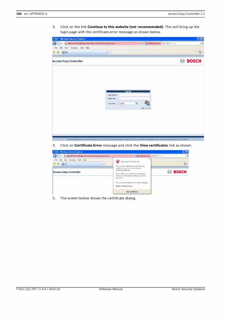
7/18/2019 User_Guide___Instruction_Book_enUS_1385855115.pdf
http://slidepdf.com/reader/full/userguideinstructionbookenus1385855115pdf 182/194
182 en | APPENDIX A Access Easy Controller 2.1
F.01U.122.797 | 1.0.4 | 2010.10 Software Manual Bosch Security Systems
3. Click on the link Continue to this website (not recommended). This will bring up the
login page with the certificate error message as shown below.
4. Click on Certificate Error message and click the View certificates link as shown.
5. The screen below shows the certificate dialog.

7/18/2019 User_Guide___Instruction_Book_enUS_1385855115.pdf
http://slidepdf.com/reader/full/userguideinstructionbookenus1385855115pdf 183/194
Access Easy Controller 2.1 APPENDIX A | en 183
Bosch Security Systems Software Manual F.01U.122.797 | 1.0.4 | 2010.10
6. In the General tab, click Install Certificates. The screen below appears.
7. Click the Next button to start importing the certificate.

7/18/2019 User_Guide___Instruction_Book_enUS_1385855115.pdf
http://slidepdf.com/reader/full/userguideinstructionbookenus1385855115pdf 184/194
184 en | APPENDIX A Access Easy Controller 2.1
F.01U.122.797 | 1.0.4 | 2010.10 Software Manual Bosch Security Systems
8. Select the radio button Place all certificates in the following store. Click the Browse
button to select a location to save the certificates. The following window pops up for you
to select the location.
9. Select the location Trusted Root Certificate Authorities and click the OK button.

7/18/2019 User_Guide___Instruction_Book_enUS_1385855115.pdf
http://slidepdf.com/reader/full/userguideinstructionbookenus1385855115pdf 185/194
Access Easy Controller 2.1 APPENDIX A | en 185
Bosch Security Systems Software Manual F.01U.122.797 | 1.0.4 | 2010.10
10. Click the Finish button to complete the installation. The following security warning
prompts.
11. Click Yes to complete the installation. Enter the AEC2.1's IP address in the browser's
Address box and the AEC2.1 login page appears without the certificate error message.

7/18/2019 User_Guide___Instruction_Book_enUS_1385855115.pdf
http://slidepdf.com/reader/full/userguideinstructionbookenus1385855115pdf 186/194
186 en | APPENDIX B Access Easy Controller 2.1
F.01U.122.797 | 1.0.4 | 2010.10 Software Manual Bosch Security Systems
24 APPENDIX B
This chapter explains the steps to configure the IP address of the system.
24.1 Procedure to set the IP Address of computer
This section provides procedure to set the IP Address for the PC.
Follow through the procedures to set the IP Address of the PC.
1. Click the button, followed by Settings > Control Panel > Network
Connections
2. Double-click the existing network connection icon and select Properties, the
screen below appears.
3. Look up for Internet Protocol TCP/IP from the list. If the component is found, highlight it
by single clicking on it. Then skip forward to step 8 of this procedure. However if the
component is not found, continue with steps 4 to 7 and install the component.
NOTICE!
The example described here is based on Windows 98 and Internet Explorer 5.
Differencesmight appear for the dialog box, displays, or description if other version or
different operatingsystem is used. However, the principle of setting is the same.

7/18/2019 User_Guide___Instruction_Book_enUS_1385855115.pdf
http://slidepdf.com/reader/full/userguideinstructionbookenus1385855115pdf 187/194
Access Easy Controller 2.1 APPENDIX B | en 187
Bosch Security Systems Software Manual F.01U.122.797 | 1.0.4 | 2010.10
4. If Internet Protocol TCP/IP is not found, then you need to install it. To add the TCP/IP
component, click the button, the screen below appears:
5. Highlight the Protocol by single clicking on it, and then click the button.
6. The dialog box below appears. From this box, select Microsoft TCP/IP version 6 in the
Network Protocol window.
7. Click the button to proceed with the component installation. Follow any
instructions that may be displayed on the screen. Note that the system may ask you to
insert your Windows Installation Disk in the CD ROM drive. When done, go back to step 3
and select the TCP/IP Protocol - network adapter line from the list of installed network
components. Then proceed to step. 8.
8. With the TCP/IP - adapter component highlighted, click the button to
define the TCP/IP Properties. The TCP/IP properties dialog box appears as shown below

7/18/2019 User_Guide___Instruction_Book_enUS_1385855115.pdf
http://slidepdf.com/reader/full/userguideinstructionbookenus1385855115pdf 188/194
188 en | APPENDIX B Access Easy Controller 2.1
F.01U.122.797 | 1.0.4 | 2010.10 Software Manual Bosch Security Systems
9. Select Use the following IP address radio button. This will enable the fields for IP
Address and Subnet Mask.
10. Enter the IP Address and Subnet Mask Address. The following examples shows the
recommended address and subnet mask to assign to the computer to communicate with
a brand new AEC2.1 as received from the factory. Leave DNS field blank

7/18/2019 User_Guide___Instruction_Book_enUS_1385855115.pdf
http://slidepdf.com/reader/full/userguideinstructionbookenus1385855115pdf 189/194
Access Easy Controller 2.1 APPENDIX B | en 189
Bosch Security Systems Software Manual F.01U.122.797 | 1.0.4 | 2010.10
11. Click the button after verifying the IP address and subnet mask.
12. The computer will proceed to configure the TCP/IP settings. When completed, you will be
prompted to reboot the computer for the new settings to take effect.

7/18/2019 User_Guide___Instruction_Book_enUS_1385855115.pdf
http://slidepdf.com/reader/full/userguideinstructionbookenus1385855115pdf 190/194
190 en | APPENDIX C Access Easy Controller 2.1
F.01U.122.797 | 1.0.4 | 2010.10 Software Manual Bosch Security Systems
25 APPENDIX C
25.1 Activity Transactions
This appendix list the various Activity transactions found within each category.
25.2 Alarm Activity
25.3 Restore Activity
25.4 Valid Activity
No Transactions
1 Access Denied
2 Invalid Schedule
3 Invalid Start Date
4 Invalid End Date
5 Duress
6 Access Denied - Wrong PIN
7 Access Denied - Passback
8 Access Denied - Timed APB
9 Exit Denied - Passback
10 Invalid Card
11 Door Forced Opened
12 Door Held Open
13 Panel Tamper
14 Panel AC Failure
15 Alarm
16 Auto Deny Access
7 Exit Denied
No Transactions
1 Door Closed
2 Tamper Restored
3 Alarm Restored
4 Power Restored
No Transactions
1 Access Granted
2 Exit Granted
3 Access Granted, Soft APB
4 Exit Granted, Soft APB
5 PIN Changed
6 Disarmed
7 Armed

7/18/2019 User_Guide___Instruction_Book_enUS_1385855115.pdf
http://slidepdf.com/reader/full/userguideinstructionbookenus1385855115pdf 191/194
Access Easy Controller 2.1 APPENDIX C | en 191
Bosch Security Systems Software Manual F.01U.122.797 | 1.0.4 | 2010.10
25.5 Time Attendance
8 Turn On
9 Turn Off
10 Door Locked
11 Door Unlocked
12 Door Locked By Schedule
13 Door Unlocked By Schedule
14 Door Momentarily Unlocked
15 Door Access Enabled
16 Door Access Disabled
17 Armed By Schedule
18 Disarmed By Schedule
19 Bypassed
20 Turned Off By Schedule
21 Turned On By Schedule22 Duration Off
23 Duration On
24 Grant Access
25 Auto Grant Access
26 Access Granted - No Entry
27 Exit Granted - No Entry
28 Access Soft APB - No Entry
29 Exit Soft APB - No Entry
30 Grant Access - No Entry
31 Auto Grant Access - No Entry
No Transactions
No Transactions
1 Clock In
2 Clock Out

7/18/2019 User_Guide___Instruction_Book_enUS_1385855115.pdf
http://slidepdf.com/reader/full/userguideinstructionbookenus1385855115pdf 192/194

7/18/2019 User_Guide___Instruction_Book_enUS_1385855115.pdf
http://slidepdf.com/reader/full/userguideinstructionbookenus1385855115pdf 193/194

7/18/2019 User_Guide___Instruction_Book_enUS_1385855115.pdf
http://slidepdf.com/reader/full/userguideinstructionbookenus1385855115pdf 194/194
Related Documents


