GMW USER’S MANUAL MODEL: 3470 45MM ELECTROMAGNET Date Sold: _______________ Serial number: ___________ PROPRIETARY THIS DOCUMENT CONTAINS CONFIDENTIAL INFORMATION PROPRIETARY TO GMW ASSOCIATES. IT MUST NOT BE REPRODUCED OR DISCLOSED TO OTHERS OR USED IN ANY WAY EXCECPT FOR THE INSTALLATION, OPERATION OR MAINTENANCE OF GMW ASSOCIATES PRODUCTS. This manual is for the model 3470 electromagnet with serial numbers 195 and below. For the model 3470 electromagnet with serial numbers 196 to 205 see manual M3470d. For the model 3470 electromagnet with serial numbers 206 and below see manual 3470e. File No: M3470c.407 Revision Date: March 20, 2007 ________________________________________________ GMW 955 Industrial Road, San Carlos, CA 94070 Tel: (650) 802-8292 Fax: (650) 802-8298 Email: [email protected] Web site: http://www.gmw.com

Welcome message from author
This document is posted to help you gain knowledge. Please leave a comment to let me know what you think about it! Share it to your friends and learn new things together.
Transcript

GMW
USER’S MANUAL
MODEL: 3470
45MM ELECTROMAGNET
Date Sold: _______________
Serial number: ___________
PROPRIETARYTHIS DOCUMENT CONTAINS CONFIDENTIAL INFORMATIONPROPRIETARY TO GMW ASSOCIATES. IT MUST NOT BE REPRODUCED OR DISCLOSED TO OTHERS OR USED IN ANY WAY EXCECPT FOR THE INSTALLATION, OPERATION OR MAINTENANCE OF GMW ASSOCIATES PRODUCTS.
This manual is for the model 3470 electromagnet with serial numbers 195 and below.For the model 3470 electromagnet with serial numbers 196 to 205 see manual M3470d.For the model 3470 electromagnet with serial numbers 206 and below see manual 3470e.
File No: M3470c.407 Revision Date: March 20, 2007________________________________________________
GMW 955 Industrial Road, San Carlos, CA 94070 Tel: (650) 802-8292 Fax: (650) 802-8298Email: [email protected] Web site: http://www.gmw.com

TABLE OF CONTENTS
SPECIFICATIONS Section 1Table 1 Model 3470 General SpecificationsTable 2 Model 3470 Electrical and Water Connections
WARNINGS [ Refer to this section before operation of Electromagnet ] Section 2
INSTALLATION Section 3Unpacking InstructionsMounting PositionPole Selection and InstallationElectrical CircuitInterlocksCooling
OPERATION Section 4GeneralCalibrationField Control Operation
MAINTENANCE Section 5
STANDARD OPTIONS Section 6Probe Holder
CUSTOM OPTIONS Section 7
EXCITATION CURVES Section 8
TEST DATA Section 9
DRAWINGS Section 10Elmwood 3450 ThermostatsDrawing 11801470-C 3470 Electromagnet General Assembly (Serial numbers 195 and below)Drawing 11900010 3470/PT6010 Electromagnet Electrical AssemblyDrawing 13900130 3470/PT6010 Electromagnet Electrical WiringDrawing 11900020 3470/BOP50-8 Electromagnet Electrical Assembly
Continued

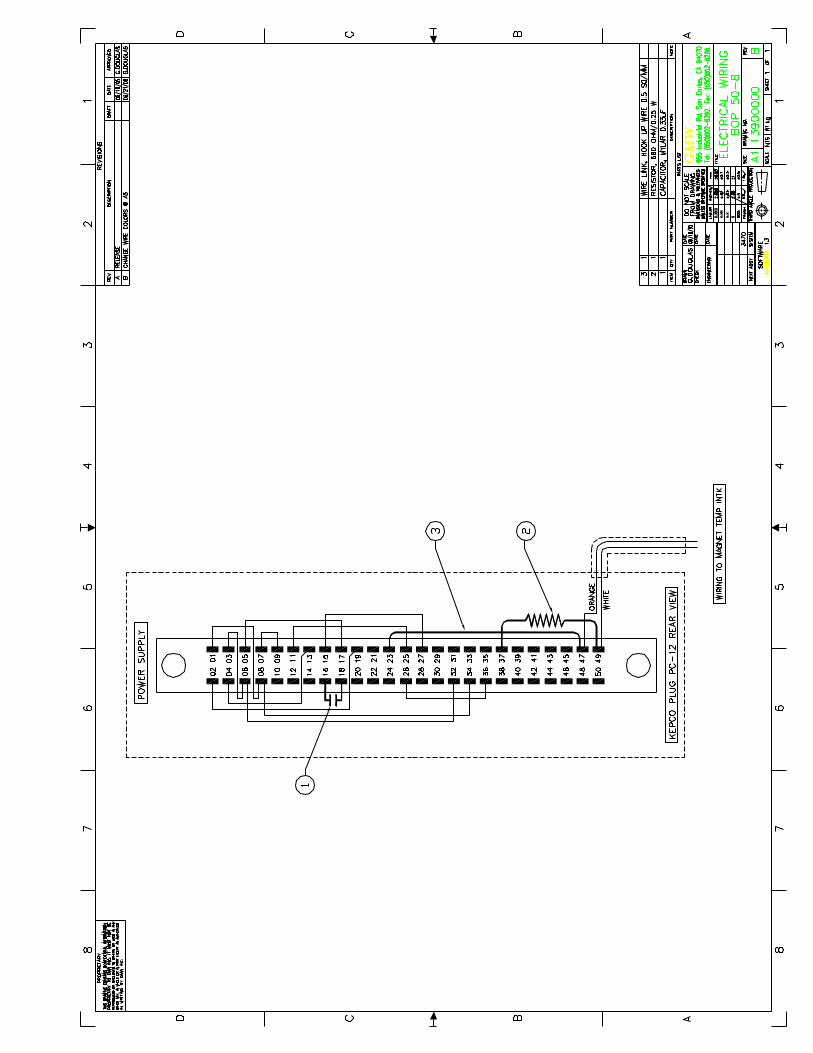
DRAWINGSDrawing 113900140 3470/BOP50-8 Electromagnet Electrical Wiring
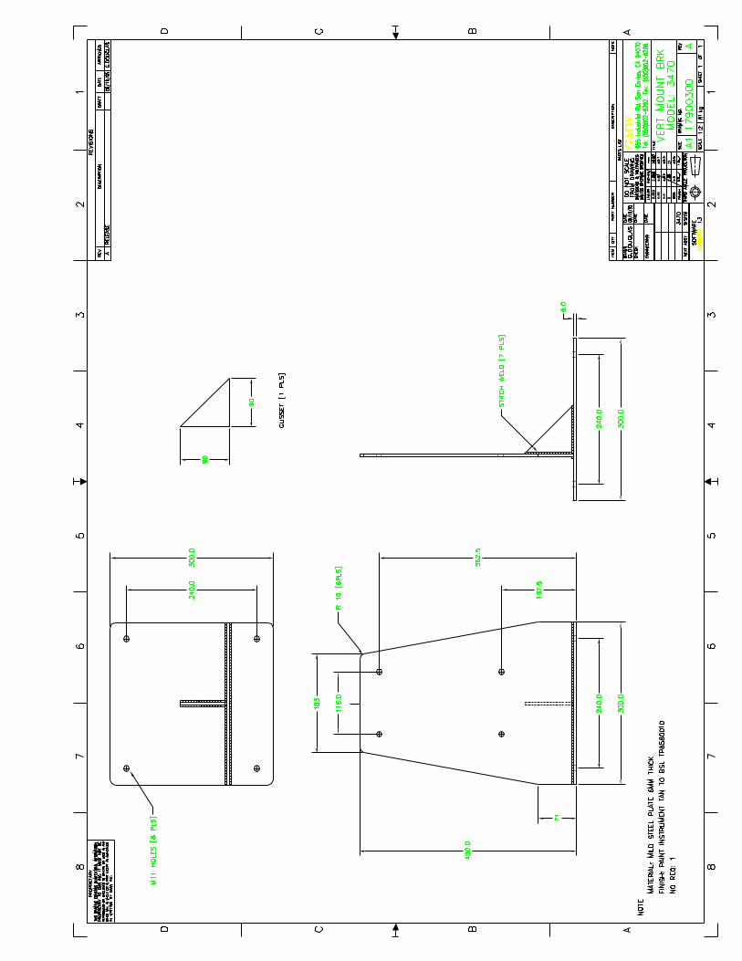
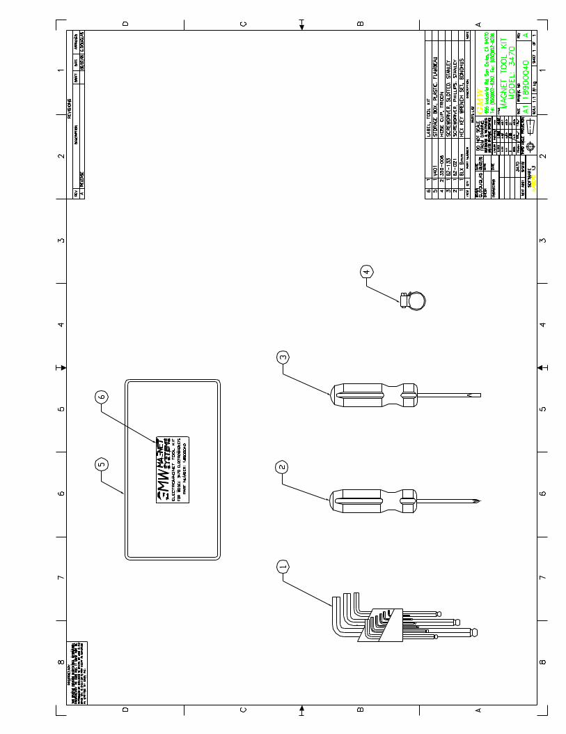
Drawing 11900000 Electromagnet Assembly to Vertical MountDrawing 17900300 Electromagnet Vertical Mount BracketDrawing 18900040 Electromagnet Tool KitDrawing 17801500 Pole Cylindrical/Tapered (40/20mm)Drawing 17802760 Square Pole Cap (45mm)Drawing 18900391 Shipping Crate Assembly
Drawing 113900000 3470/BOP50-8 Electromagnet Electrical Wiring
Section 1SPECIFICATIONS
Table 1. Model 3470 Specifications
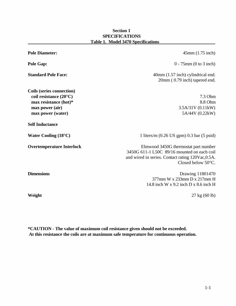
Pole Diameter: 45mm (1.75 inch)
Pole Gap: 0 - 75mm (0 to 3 inch)
Standard Pole Face: 40mm (1.57 inch) cylindrical end. 20mm ( 0.79 inch) tapered end.
Coils (series connection) coil resistance (20°C) 7.3 Ohm max resistance (hot)* 8.8 Ohm max power (air) 3.5A/31V (0.11kW) max power (water) 5A/44V (0.22kW)
Self Inductance
Water Cooling (18°C) 1 liters/m (0.26 US gpm) 0.3 bar (5 psid)
Overtemperature Interlock Elmwood 3450G thermostat part number3450G 611-1 L50C 89/16 mounted on each coiland wired in series. Contact rating 120Vac,0.5A.
Closed below 50°C.
Dimensions Drawing 11801470377mm W x 233mm D x 217mm H
14.8 inch W x 9.2 inch D x 8.6 inch H
Weight 27 kg (60 lb)
*CAUTION - The value of maximum coil resistance given should not be exceeded. At this resistance the coils are at maximum safe temperature for continuous operation.
1-1
Section 1SPECIFICATIONS
Table 2. Model 3470 Electrical and Water Connections
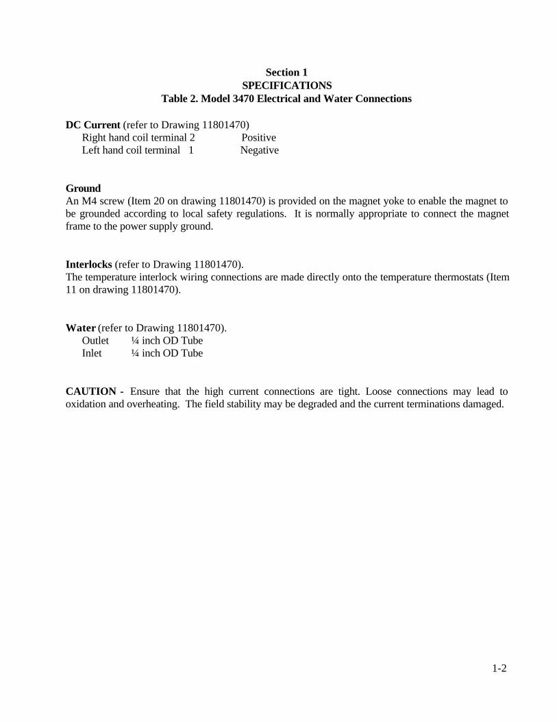
DC Current (refer to Drawing 11801470)Right hand coil terminal 2 PositiveLeft hand coil terminal 1 Negative
GroundAn M4 screw (Item 20 on drawing 11801470) is provided on the magnet yoke to enable the magnet tobe grounded according to local safety regulations. It is normally appropriate to connect the magnetframe to the power supply ground.
Interlocks (refer to Drawing 11801470).The temperature interlock wiring connections are made directly onto the temperature thermostats (Item11 on drawing 11801470).
Water (refer to Drawing 11801470).Outlet ¼ inch OD TubeInlet ¼ inch OD Tube
CAUTION - Ensure that the high current connections are tight. Loose connections may lead tooxidation and overheating. The field stability may be degraded and the current terminations damaged.
1-2
Section 2
WARNINGS
REFER TO WARNINGS BELOW BEFORE OPERATING ELECTROMAGNET
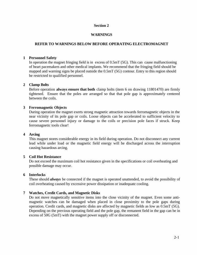
1 Personnel SafetyIn operation the magnet fringing field is in excess of 0.5mT (5G). This can cause malfunctioningof heart pacemakers and other medical implants. We recommend that the fringing field should bemapped and warning signs be placed outside the 0.5mT (5G) contour. Entry to this region shouldbe restricted to qualified personnel.
2 Clamp BoltsBefore operation always ensure that both clamp bolts (item 6 on drawing 11801470) are firmlytightened. Ensure that the poles are arranged so that that pole gap is approximately centeredbetween the coils.
3 Ferromagnetic ObjectsDuring operation the magnet exerts strong magnetic attraction towards ferromagnetic objects in thenear vicinity of its pole gap or coils. Loose objects can be accelerated to sufficient velocity tocause severe personnel injury or damage to the coils or precision pole faces if struck. Keepferromagnetic tools clear!
4 ArcingThis magnet stores considerable energy in its field during operation. Do not disconnect any currentlead while under load or the magnetic field energy will be discharged across the interruptioncausing hazardous arcing.
5 Coil Hot ResistanceDo not exceed the maximum coil hot resistance given in the specifications or coil overheating andpossible damage may occur.
6 InterlocksThese should always be connected if the magnet is operated unattended, to avoid the possibility ofcoil overheating caused by excessive power dissipation or inadequate cooling.
7 Watches, Credit Cards, and Magnetic DisksDo not move magnetically sensitive items into the close vicinity of the magnet. Even some anti-magnetic watches can be damaged when placed in close proximity to the pole gaps duringoperation. Credit cards, and magnetic disks are affected by magnetic fields as low as 0.5mT (5G).Depending on the previous operating field and the pole gap, the remanent field in the gap can be inexcess of 50G (5mT) with the magnet power supply off or disconnected.
2-1

Section 3
INSTALLATION
Caution: This is a heavy system. All movement, lifting and installation of the 3470 Electromagnetmust be under the supervision of an experienced person to prevent the possibility of serious injury ordamage to the Electromagnet and associated equipment.
Unpacking Instructions and Damage InspectionTo unpack the electromagnet please use the following procedure (Refer to Drawing 18800450).
1. First remove all of the "Posidrive Screws" located at the lower edge of all the side panels of the"Crate Top Cover".
2. Gently rock the "Crate Top Cover" to work it loose from the shipping crate base.
3. Grip the side panels of the Crate Top Cover. Lift "Crate Top Cover" high enough to clear top ofelectromagnet, move cover to a clear area.
4. Inspect the magnet to ensure that no damage has occurred to the magnet in shipment. If damage isevident report the damage in detail to the shipper for claim and simultaneously notify GMW incase assessment of the damage must be made. If no damage is found proceed with magnetunpacking and installation.
5. Remove the M8 Hex Head Coach Bolts that secure the magnet to the shipping crate base.
6. The magnet is now prepared for final installation. Follow the appropriate procedure for direct orbase mounting listed below.
Direct Mounting1. Move magnet to final location and bolt magnet down through the four mounting holes provided in
the magnet angle bracket (refer drawing 11801470)
Pole Selection and Installation (Refer to drawing 11801470).Using the field uniformity and induction curves determine the most desirable pole; cylindrical or
tapered. In general:
If a uniform field is required use a cylindrical pole end.If a high field is required use a tapered pole end.
Pole removal (refer to drawing 11801470).1. Turn off the power supply.2. Loosen the two pole clamping bolts (item 6 on drawing 11801470).3. Slide the pole out of the magnet yoke.
3-1

Section 3
INSTALLATION
Pole fitting (refer to drawing 11801470).1. Ensure the poles and pole sleeves are clean and free from debris.2. Reverse the pole removal sequence above.
Electrical CircuitNever connect or remove cables from the magnet with the power supply connected. The stored energyin the magnet can cause arcing resulting in severe injury to personnel or equipment damage.
The magnet has two coils which are connected in series. (Refer to drawing 11801470). The powersupply cables should be connected directly to the dc current terminals marked + and -. Recommendedcurrent cable for the 3470 is stranded copper of 1.5 mm² cross section (16 AWG).
Because the magnet stores a significant amount of energy in its magnetic field, special care should betaken to insure that the current terminations are secure and cannot work loose in operation. Localheating at the terminations can cause rapid oxidation leading to a high contact resistance and highpower dissipation at the terminals. If left unattended this can cause enough local heating to damage theterminals and the coils.
The 3470 InterlocksThe Model 3470 has two thermostats, Elmwood 3450G Part Number 3450G611-1 L50C 89/16. Theyare located on the outer coil cooling plate and wired in series. The thermostats are normally closed,opening when the coil cooling plate temperature exceeds 50°C +/3°C.
CoolingThe Model 3470 can be operated to an average coil temperature of 70°C. Assuming an ambientlaboratory temperature of 20°C and a temperature coefficient of resistivity for copper of 0.0039/°C,the hot resistance of the coil should not exceed 20% more than the ambient temperature "cold"resistance. The coil thermostat will open when either coil cooling plate temperature exceedsapproximately 50°C . Clean, cool (16°C - 20°C) water at 1 l/min at 0.3 bar (5 psid) should be used tocool the 3470 magnet.
The cooling copper tubes are electrically isolated from the coils to avoid electrochemical corrosion.A 50 micron filter should be placed before the input to the magnet to trap particulates and avoidunreliable operation of the water flow switch interlock if fitted.
For continuous operation of the magnet it may be appropriate to use a recirculating chiller to reducewater and drainage costs. The chiller capacity will depend on whether cooling is required for themagnet alone or magnet and power supply. For the Model 3470 Electromagnet alone a suitable chilleris the Bay Voltex model: RRS-090.
3-2

Section 3
INSTALLATION
Cooling - continuedFor recirculating cooling systems use distilled or deionized water with a biocide to prevent bacterialgrowth and corrosion. Do not use corrosion inhibitors in high quality electrical systems since thewater conductivity is increased which can result in increased leakage currents and electrochemicalcorrosion.
At currents of approximately 3.50A and below the Model 3470 can be operated safely without watercooling. However the coil temperature will vary with the power dissipation. This results indimensional changes of the magnet yoke and air cooling is not suitable when high field stability isrequired.
Freon, oil, ethylene glycol or other cooling mediums can be used. The flow required will beapproximately inversely proportional to their specific heats. An experimental determination of theflow and pressure required will be necessary.
Avoid cooling the magnet below the dew point of the ambient air. Condensation may cause electricalshorts and corrosion.
During operation the resistance can be checked using a voltmeter across each coil. The voltage willrise to a constant value once thermal equilibrium has been reached. If it is desired to save water, theflow can be reduced until the hot resistance is approached. NOTE: This adjustment must be madeslowly enough to allow for the thermal inertia of the coils.
3-3

Section 4
OPERATION
GeneralThe magnet operates as a conventional electromagnet.
1. Adjust the poles to the desired gap with the poles approximately symmetrical about the centermagnet line.
2. Adjust the cooling water flow to about 1 liters/min (0.26 USgpm) for the 3470. For operation atless than maximum power the water flow may be correspondingly reduced. Note that the inletwater temperature will determine the actual flow rate required. The above specified flow rateswere determined with a water inlet temperature of approximately 18°C.
3. Turn on the power supply and increase the current until the desired field is reached.
CalibrationThe induction curves may be used to estimate the field in the air gap to within four or five percent.More accurate field determination may be obtained by deriving experimentally a calibration curve forthe particular pole and air gap combination being used. Magnetic hysteresis in the yoke and poles cancause an error of 30 to 70G (3 to 7mT) with an arbitrary application of such a calibration curve. Thiseffect may be reduced to less than one percent by following a prescribed 'current setting schedule'designed to make the magnet 'forget' its prior magnetic history. The schedule should of course be usedboth in establishing the calibration curve and in its subsequent use. A possible schedule would be:
From zero current, increase to maximum current and reduce again to zero current. Increase again tomaximum current and reduce to the current to give the desired field setting. Approaching the desiredfield from a higher setting will typically produce better field uniformity. This is because the fieldchanges at the pole edges will normally lag the field change at the center thereby helping tocompensate the radial decrease in field.
Greater precision in setting up the calibration curve will be achieved with the use of a digitalteslameter and by making a numerical table. This table used with an interpolation routine willeliminate the error associated with reading a graph.
In any event, three points need to be remembered:
1. A calibration curve or table is only as good as the precision employed in generating it.
2. The field is defined only at the point it is measured. It will generally be different at a different pointin the air gap. For example, the induction curves refer to the field on the pole axis and at the center ofthe air gap (median plane).
4-1

Section 4
OPERATION
Calibration - continued3. The field is most directly a function of the current in the magnet coils. Voltage across the coils is
not a good measure of field since the electrical resistance of the coils depends on the temperature(about 0.4% per degree Celsius).
Field Control OperationThe necessity to use calibration curves can be avoided by using a field controller to sense themagnetic field and provide a corresponding power supply control signal through the power supplyprogramming inputs. Contact GMW for suitable instrumentation.
4-2

Section 5
MAINTENANCE
Periodically check that the poles are clean, properly lubricated and free of grit and dirt, which maycause binding. Be very careful not to damage the relatively soft pole surface since this may degradethe magnetic field uniformity in the gap.
Note that the surface treatments used provide good corrosion protection but in order to maintain theinherent mechanical precision of the magnet, heavy build-up of plating materials is deliberatelyavoided. As a result, high humidity or otherwise seriously corrosive atmospheres can causecorrosion. Periodically apply an appropriate corrosion protection, particularly when the magnet isstored for an extended period.
Check the cooling water circuit to ensure the water is clean and free of debris and bacterial growth.Ensure the in-line water filter (if fitted) is clean.
5-1

Section 6
STANDARD OPTIONS


Section 7
CUSTOM OPTIONS


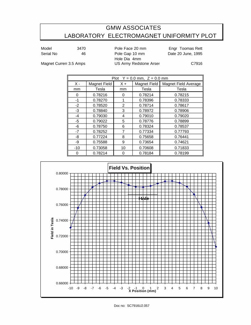
GMW ASSOCIATES LABORATORY ELECTROMAGNET UNIFORMITY PLOT
Model 3470 Pole Face 20 mm Engr Toomas RettSerial No 46 Pole Gap 10 mm Date 20 June, 1995
Hole Dia 4mmMagnet Current3.5 Amps US Army Redstone Arsenal C7916
Plot Y = 0.0 mm, Z = 0.0 mmX - Magnet Field X + Magnet Field Magnet Field Average
mm Tesla mm Tesla Tesla0 0.78216 0 0.78214 0.78215 0.000-1 0.78270 1 0.78396 0.78333 0.002-2 0.78520 2 0.78714 0.78617 0.005-3 0.78840 3 0.78972 0.78906 0.009-4 0.79030 4 0.79010 0.79020 0.010-5 0.79022 5 0.78776 0.78899 0.009-6 0.78750 6 0.78324 0.78537 0.004-7 0.78252 7 0.77334 0.77793 -0.005-8 0.77224 8 0.75658 0.76441 -0.023-9 0.75588 9 0.73654 0.74621 -0.046
-10 0.73058 10 0.70608 0.71833 -0.0820 0.78214 0 0.78184 0.78199
Doc no: SC7916U1.057
Uniformity Plot
-0.100
-0.080
-0.060
-0.040
-0.020
0.000
0.020
0.040
0 1 2 3 4 5 6 7 8 9 10
X AXIS (mm)
Fie
ld D
evia
tio
n
∆ B / B
GMW ASSOCIATES LABORATORY ELECTROMAGNET UNIFORMITY PLOT
Model 3470 Pole Face 20 mm Engr Toomas RettSerial No 46 Pole Gap 10 mm Date 20 June, 1995
Hole Dia 4mmMagnet Current3.5 Amps US Army Redstone Arsenal C7916
Plot Y = 0.0 mm, Z = 0.0 mmX - Magnet Field X + Magnet Field Magnet Field Average
mm Tesla mm Tesla Tesla
0 0.78216 0 0.78214 0.78215 0.000-1 0.78270 1 0.78396 0.78333 0.002-2 0.78520 2 0.78714 0.78617 0.005-3 0.78840 3 0.78972 0.78906 0.009-4 0.79030 4 0.79010 0.79020 0.010-5 0.79022 5 0.78776 0.78899 0.009-6 0.78750 6 0.78324 0.78537 0.004-7 0.78252 7 0.77334 0.77793 -0.005-8 0.77224 8 0.75658 0.76441 -0.023-9 0.75588 9 0.73654 0.74621 -0.046
-10 0.73058 10 0.70608 0.71833 -0.0820 0.78214 0 0.78184 0.78199
Doc no: SC7916U2.057
Field Vs. Position
0.66000
0.68000
0.70000
0.72000
0.74000
0.76000
0.78000
0.80000
-10 -9 -8 -7 -6 -5 -4 -3 -2 -1 0 1 2 3 4 5 6 7 8 9 10X Position (mm)
Fie
ld in
Tes
la
Hole


Section 8
EXCITATION CURVES

GMW AssociatesElectromagnet Excitation Plot
Field Vs Gap
Contract No: Page: 1 of 1 Date: Sept 22, 95Customer: Engr: G.Douglas
Model: 3470 Power Supply: Soren DCS 55-55 Set Current: 5.0 AmpsSerial No: 52 Serial No: D1285 Target Field:
Pole Face: As per table below Position: X=0, Y=0, Z=0Serial No: None Notes: Coil position set to minimum gapPole Gap: As per table belowPole Spacers: None
0.0
0.2
0.4
0.6
0.8
1.0
1.2
1.4
1.6
1.8
2.0
0 5 10 15 20 25 30 35 40 45
Gap in mm
Fie
ld in
Tes
la
20
40
Sq
Pole Face
Filename: 3470 Gap-Field.xls Revised: March 13, 2000

GMW AssociatesElectromagnet Excitation Plot
Field Vs Current
Contract No: Page: 1 of 3 Date: Sept 22, 95Customer: Engr: G.Douglas
Model: 3470 Power Supply: Set Current: Serial No: 52 Serial No: Target Field:
Pole Face: 40 Position: X=0, Y=0, Z=0Serial No: None Notes: Coil position set to minimum gapPole Gap: As per table belowPole Spacers: None
0.0
0.5
1.0
1.5
2.0
0.0 1.0 2.0 3.0 4.0 5.0 6.0
Current in Amps
Fie
ld in
Tes
la
05
7.5
10
15
20
30
40
Gap mm
Filename: 3470 Ex 40-05-40.xls

GMW AssociatesElectromagnet Excitation Plot
Field Vs Current
Contract No: Page: 2 of 3 Date: Sept 22, 95Customer: Engr: G.Douglas
Model: 3470 Power Supply: Set Current: Serial No: 52 Serial No: Target Field:
Pole Face: 20 Position: X=0, Y=0, Z=0Serial No: None Notes: Coil position set to minimum gapPole Gap: As per table belowPole Spacers: None
0.0
0.5
1.0
1.5
2.0
0.0 1.0 2.0 3.0 4.0 5.0 6.0
Current in Amps
Fie
ld in
Tes
la
05
7.5
10
15
20
30
40
Gap mm
Filename: 3470 Ex 20-05-40.xls
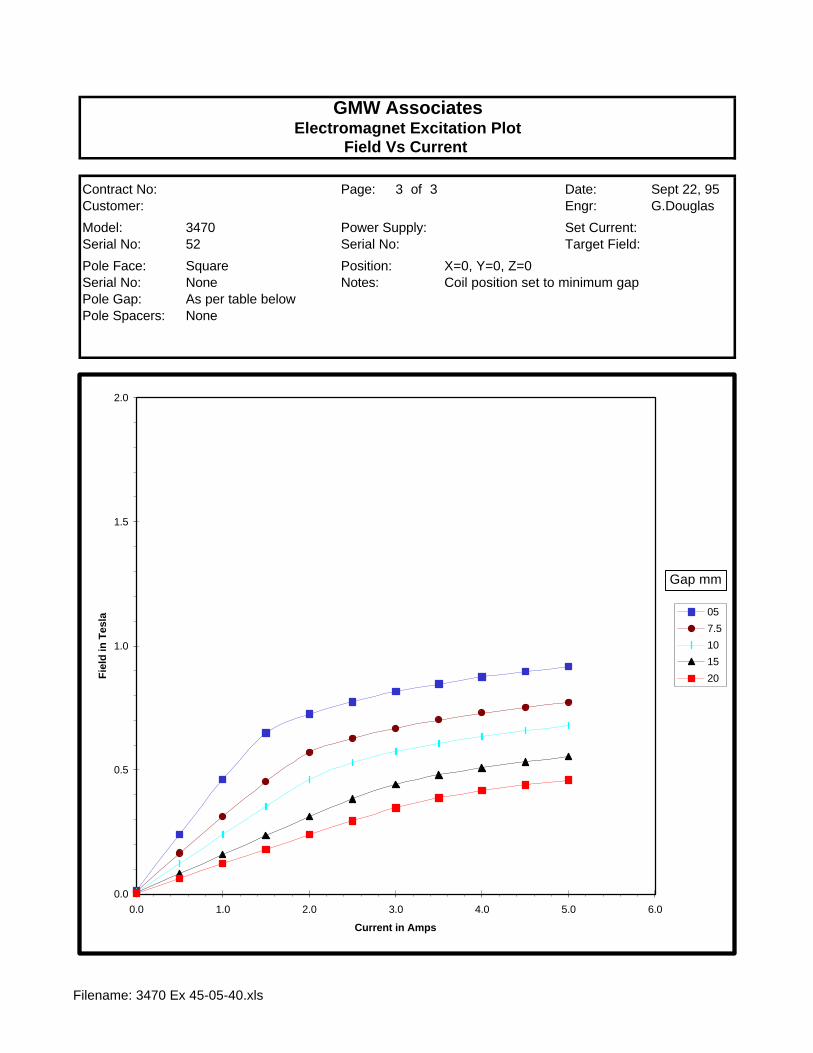
GMW AssociatesElectromagnet Excitation Plot
Field Vs Current
Contract No: Page: 3 of 3 Date: Sept 22, 95Customer: Engr: G.Douglas
Model: 3470 Power Supply: Set Current: Serial No: 52 Serial No: Target Field:
Pole Face: Square Position: X=0, Y=0, Z=0Serial No: None Notes: Coil position set to minimum gapPole Gap: As per table belowPole Spacers: None
0.0
0.5
1.0
1.5
2.0
0.0 1.0 2.0 3.0 4.0 5.0 6.0
Current in Amps
Fie
ld in
Tes
la
05
7.5
10
15
20
Gap mm
Filename: 3470 Ex 45-05-40.xls
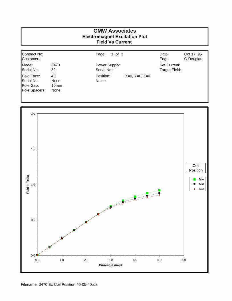
GMW AssociatesElectromagnet Excitation Plot
Field Vs Current
Contract No: Page: 1 of 3 Date: Oct 17, 95Customer: Engr: G.Douglas
Model: 3470 Power Supply: Set Current: Serial No: 52 Serial No: Target Field:
Pole Face: 40 Position: X=0, Y=0, Z=0Serial No: None Notes: Pole Gap: 10mmPole Spacers: None
0.0
0.5
1.0
1.5
2.0
0.0 1.0 2.0 3.0 4.0 5.0 6.0
Current in Amps
Fie
ld in
Tes
la
Min
Mid
Max
Coil Position
Filename: 3470 Ex Coil Position 40-05-40.xls
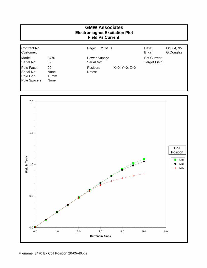
GMW AssociatesElectromagnet Excitation Plot
Field Vs Current
Contract No: Page: 2 of 3 Date: Oct 04, 95Customer: Engr: G.Douglas
Model: 3470 Power Supply: Set Current: Serial No: 52 Serial No: Target Field:
Pole Face: 20 Position: X=0, Y=0, Z=0Serial No: None Notes: Pole Gap: 10mmPole Spacers: None
0.0
0.5
1.0
1.5
2.0
0.0 1.0 2.0 3.0 4.0 5.0 6.0
Current in Amps
Fie
ld in
Tes
la
Min
Mid
Max
Coil Position
Filename: 3470 Ex Coil Position 20-05-40.xls

GMW AssociatesElectromagnet Excitation Plot
Field Vs Current
Contract No: Page: 3 of 3 Date: Oct 17, 95Customer: Engr: G.Douglas
Model: 3470 Power Supply: Set Current: Serial No: 52 Serial No: Target Field:
Pole Face: 45 Square Position: X=0, Y=0, Z=0Serial No: None Notes: Pole Gap: 10mmPole Spacers: None
0.0
0.5
1.0
1.5
2.0
0.0 1.0 2.0 3.0 4.0 5.0 6.0
Current in Amps
Fie
ld in
Tes
la
Mid
Max
Coil Position
Filename: 3470 Ex Coil Position 45-05-40.xls

Section 9
TEST DATA


GMW ASSOCIATES LABORATORY ELECTROMAGNET UNIFORMITY PLOT
Model 3470 Pole Face 20 mm Engr Greg DouglasSerial No 52 Pole Gap 10 mm Date Sept 25, 1995
Magnet Current 5.0 Amps
Plot Y = 0.0 mm, Z = 0.0 mmX - Magnet Field X + Magnet Field Magnet Field Average
mm Tesla mm Tesla Tesla0 1.0120600 0 1.0119800 1.0120200 0.000-1 1.0120200 1 1.0118600 1.0119400 0.000-2 1.0115000 2 1.0110400 1.0112700 -0.001-3 1.0102600 3 1.0109820 1.0106210 -0.001-4 1.0087600 4 1.0073000 1.0080300 -0.004-5 1.0047000 5 1.0030600 1.0038800 -0.008-6 0.9992600 6 0.9965600 0.9979100 -0.014-7 0.9878800 7 0.9861200 0.9870000 -0.025-8 0.9701000 8 0.9692600 0.9696800 -0.042-9 0.9437000 9 0.9407800 0.9422400 -0.069
-10 0.9081200 10 0.9034000 0.9057600 -0.1050 1.0119800 0 1.0120400 1.0120100
Doc no: S3470U01
Uniformity Plot
-0.180
-0.160
-0.140
-0.120
-0.100
-0.080
-0.060
-0.040
-0.020
0.000
0.020
0 1 2 3 4 5 6 7 8 9 10
X AXIS (mm)
Fie
ld D
evia
tio
n
∆ B / B

GMW ASSOCIATESLABORATORY ELECTROMAGNET UNIFORMITY PLOT
Model 3470 Pole Face 20 mm Engr Greg DouglasSerial No 52 Pole Gap 10 mm Date Sept 25, 1995
Magnet Current 5.0 Amps
Plot Y = 0.0 mm, X = 0.0 mmZ - Magnet Field Z + Magnet Field Magnet Field Average
mm Tesla mm Tesla Tesla0 1.012300 0 1.012280 1.012300 0.000-1 1.012940 1 1.012400 1.012670 0.000-2 1.014080 2 1.013160 1.013620 0.001-3 1.015300 3 1.013860 1.014580 0.002-4 1.016060 4 1.016060 1.016060 0.004-5 0.000000 5 0.000000 0.000000 -1.000-6 0.000000 6 0.000000 0.000000 -1.000-7 0.000000 7 0.000000 0.000000 -1.000-8 0.000000 8 0.000000 0.000000 -1.000-9 0.000000 9 0.000000 0.000000 -1.000
-10 0.000000 10 0.000000 0.000000 -1.0000 1.012300 0 1.012280 1.012290
Doc no: S3470U07.407
Uniformity Plot
-0.020
0.000
0.020
0.040
0.060
0.080
0.100
0.120
0.140
0.160
0.180
0 1 2 3 4
Z AXIS (mm)
Fie
ld D
evia
tio
n
∆ B / B

GMW ASSOCIATESLABORATORY ELECTROMAGNET UNIFORMITY PLOT
Model 3470 Pole Face 20 mm Engr Greg DouglasSerial No 52 Pole Gap 20 mm Date Sept 25, 1995
Magnet Current 5.0 Amps
Plot Y = 0.0 mm, Z = 0.0 mmX - Magnet Field X + Magnet Field Magnet Field Average
mm Tesla mm Tesla Tesla0 0.5493400 0 0.5493800 0.5493600 0.000-1 0.5489200 1 0.5489200 0.5489200 -0.001-2 0.5474000 2 0.5475200 0.5474600 -0.003-3 0.5450400 3 0.5451600 0.5451000 -0.008-4 0.5418200 4 0.5420400 0.5419300 -0.014-5 0.5366000 5 0.5365000 0.5365500 -0.023-6 0.5299200 6 0.5297600 0.5298400 -0.036-7 0.5232600 7 0.5214800 0.5223700 -0.049-8 0.5129200 8 0.5133800 0.5131500 -0.066-9 0.5010600 9 0.5027600 0.5019100 -0.086
-10 0.4887600 10 0.4899800 0.4893700 -0.1090 0.5493800 0 0.5493800 0.5493800
Doc no: S3470U03.407
Uniformity Plot
-0.180
-0.160
-0.140
-0.120
-0.100
-0.080
-0.060
-0.040
-0.020
0.000
0.020
0 1 2 3 4 5 6 7 8 9 10
X AXIS (mm)
Fie
ld D
evia
tio
n
∆ B / B

GMW ASSOCIATESLABORATORY ELECTROMAGNET UNIFORMITY PLOT
Model 3470 Pole Face 20 mm Engr Greg DouglasSerial No 52 Pole Gap 20 mm Date Oct 4, 1995
Magnet Current 5.0 Amps
Plot Y = 0.0 mm, X = 0.0 mmZ - Magnet Field Z + Magnet Field Magnet Field Average
mm Tesla mm Tesla Tesla0 0.549660 0 0.549660 0.549660 0.000-1 0.552300 1 0.548980 0.550640 0.002-2 0.556380 2 0.550040 0.553210 0.006-3 0.562000 3 0.552940 0.557470 0.014-4 0.568460 4 0.557300 0.562880 0.024-5 0.575520 5 0.563160 0.569340 0.036-6 0.581520 6 0.569660 0.575590 0.047-7 0.586900 7 0.576000 0.581450 0.058-8 0.590820 8 0.582540 0.586680 0.067-9 0.000000 9 0.000000 0.000000 -1.000
-10 0.000000 10 0.000000 0.000000 -1.0000 0.549660 0 0.549660 0.549660
Doc no: S3470U05.407
Uniformity Plot
-0.020
0.000
0.020
0.040
0.060
0.080
0.100
0.120
0.140
0.160
0.180
0 1 2 3 4 5 6 7 8
Z AXIS (mm)
Fie
ld D
evia
tio
n
∆ B / B

GMW ASSOCIATESLABORATORY ELECTROMAGNET UNIFORMITY PLOT
Model 3470 Pole Face 40 mm Engr Greg DouglasSerial No 52 Pole Gap 10 mm Date Sept 25, 1995
Magnet Current 5.0 Amps
Plot Y = 0.0 mm, Z = 0.0 mmX - Magnet Field X + Magnet Field Magnet Field Average
mm Tesla mm Tesla Tesla0 0.860880 0 0.860920 0.860900 0.000-2 0.860920 2 0.860860 0.860890 0.000-4 0.860920 4 0.860740 0.860830 0.000-6 0.860900 6 0.860640 0.860770 0.000-8 0.860800 8 0.860420 0.860610 0.000
-10 0.860400 10 0.859900 0.860150 -0.001-12 0.859540 12 0.858680 0.859110 -0.002-14 0.855520 14 0.854940 0.855230 -0.007-16 0.844000 16 0.844160 0.844080 -0.020-18 0.813680 18 0.812620 0.813150 -0.055-20 0.731560 20 0.734980 0.733270 -0.1480 0.860920 0 0.860880 0.860900
Doc no: S3470U21.407
Uniformity Plot
-0.180
-0.160
-0.140
-0.120
-0.100
-0.080
-0.060
-0.040
-0.020
0.000
0.020
0 2 4 6 8 10 12 14 16 18 20
X AXIS (mm)
Fie
ld D
evia
tio
n
∆ B / B

GMW ASSOCIATESLABORATORY ELECTROMAGNET UNIFORMITY PLOT
Model 3470 Pole Face 40 mm Engr Greg DouglasSerial No 52 Pole Gap 10 mm Date Sept 25, 1995
Magnet Current 5.0 Amps
Plot Y = 0.0 mm, X = 0.0 mmZ - Magnet Field Z + Magnet Field Magnet Field Average
mm Tesla mm Tesla Tesla0 0.859660 0 0.859720 0.859660 0.000-1 0.859740 1 0.859720 0.859730 0.000-2 0.859760 2 0.859740 0.859750 0.000-3 0.859800 3 0.859720 0.859760 0.000-4 0.000000 4 0.000000 0.000000 -1.000-5 0.000000 5 0.000000 0.000000 -1.000-6 0.000000 6 0.000000 0.000000 -1.000-7 0.000000 7 0.000000 0.000000 -1.000-8 0.000000 8 0.000000 0.000000 -1.000-9 0.000000 9 0.000000 0.000000 -1.000
-10 0.000000 10 0.000000 0.000000 -1.0000 0.859660 0 0.859720 0.859690
Doc no: S3470U09.407
Uniformity Plot
-0.020
0.000
0.020
0.040
0.060
0.080
0.100
0.120
0.140
0.160
0.180
0 1 2 3
Z AXIS (mm)
Fie
ld D
evia
tio
n
∆ B / B

GMW ASSOCIATESLABORATORY ELECTROMAGNET UNIFORMITY PLOT
Model 3470 Pole Face 40 mm Engr Greg DouglasSerial No 52 Pole Gap 20 mm Date Sept 25, 1995
Magnet Current 5.0 Amps
Plot Y = 0.0 mm, X = 0.0 mmZ - Magnet Field Z + Magnet Field Magnet Field Average
mm Tesla mm Tesla Tesla0 0.530930 0 0.530980 0.530930 0.000-1 0.531120 1 0.530950 0.531035 0.000-2 0.531490 2 0.531060 0.531275 0.001-3 0.531960 3 0.531340 0.531650 0.001-4 0.532430 4 0.531730 0.532080 0.002-5 0.533060 5 0.532310 0.532685 0.003-6 0.533500 6 0.532810 0.533155 0.004-7 0.533990 7 0.533290 0.533640 0.005-8 0.534300 8 0.533660 0.533980 0.006-9 0.000000 9 0.000000 0.000000 -1.000
-10 0.000000 10 0.000000 0.000000 -1.0000 0.530930 0 0.530980 0.530955
Doc no: S3470U11.407
Uniformity Plot
-0.020
0.000
0.020
0.040
0.060
0.080
0.100
0.120
0.140
0.160
0.180
0 1 2 3 4 5 6 7 8
Z AXIS (mm)
Fie
ld D
evia
tio
n
∆ B / B

GMW ASSOCIATESLABORATORY ELECTROMAGNET UNIFORMITY PLOT
Model 3470 Pole Face 40 mm Engr Greg DouglasSerial No 52 Pole Gap 20 mm Date Sept 25, 1995
Magnet Current 5.0 Amps
Plot Y = 0.0 mm, Z = 0.0 mmX - Magnet Field X + Magnet Field Magnet Field Average
mm Tesla mm Tesla Tesla0 0.531040 0 0.530103 0.530572 0.000-2 0.530910 2 0.530880 0.530895 0.001-4 0.530400 4 0.530300 0.530350 0.000-6 0.529350 6 0.529180 0.529265 -0.002-8 0.527310 8 0.527230 0.527270 -0.006
-10 0.524040 10 0.523480 0.523760 -0.013-12 0.518710 12 0.517320 0.518015 -0.024-14 0.509470 14 0.508250 0.508860 -0.041-16 0.494600 16 0.494310 0.494455 -0.068-18 0.470950 18 0.469040 0.469995 -0.114-20 0.438590 20 0.435750 0.437170 -0.1760 0.530103 0 0.531020 0.530562
Doc no: S3470U23.407
Uniformity Plot
-0.180
-0.160
-0.140
-0.120
-0.100
-0.080
-0.060
-0.040
-0.020
0.000
0.020
0 2 4 6 8 10 12 14 16 18 20
X AXIS (mm)
Fie
ld D
evia
tio
n
∆ B / B

GMW ASSOCIATESLABORATORY ELECTROMAGNET UNIFORMITY PLOT
Model 3470 Pole Face Square 45 mm Engr Greg DouglasSerial No 52 Pole Gap 10 mm Date Sept 22, 1995
Magnet Current 5.0 Amps
Plot Y = 0.0 mm, Z = 0.0 mmX - Magnet Field X + Magnet Field Magnet Field Average
mm Tesla mm Tesla Tesla0 0.678080 0 0.678080 0.678080 0.000-2 0.678100 2 0.678180 0.678140 0.000-4 0.678160 4 0.678140 0.678150 0.000-6 0.678220 6 0.678120 0.678170 0.000-8 0.678300 8 0.678100 0.678200 0.000
-10 0.678340 10 0.678060 0.678200 0.000-12 0.678300 12 0.677900 0.678100 0.000-14 0.677880 14 0.677340 0.677610 -0.001-16 0.676300 16 0.675700 0.676000 -0.003-18 0.671040 18 0.670160 0.670600 -0.011-20 0.655880 20 0.652620 0.654250 -0.0350 0.678080 0 0.678200 0.678140
Doc no: S3470U13.407
Uniformity Plot
-0.180
-0.160
-0.140
-0.120
-0.100
-0.080
-0.060
-0.040
-0.020
0.000
0.020
0 2 4 6 8 10 12 14 16 18 20
X AXIS (mm)
Fie
ld D
evia
tio
n
∆ B / B

GMW ASSOCIATESLABORATORY ELECTROMAGNET UNIFORMITY PLOT
Model 3470 Pole Face Square 45 mm Engr Greg DouglasSerial No 52 Pole Gap 10 mm Date Sept 22, 1995
Magnet Current 5.0 Amps
Plot Y = 0.0 mm, X = 0.0 mmZ - Magnet Field Z + Magnet Field Magnet Field Average
mm Tesla mm Tesla Tesla0 0.678180 0 0.678180 0.678180 0.000-1 0.678180 1 0.678180 0.678180 0.000-2 0.678160 2 0.678180 0.678170 0.000-3 0.678140 3 0.678180 0.678160 0.000-4 0.000000 4 0.000000 0.000000 -1.000-5 0.000000 5 0.000000 0.000000 -1.000-6 0.000000 6 0.000000 0.000000 -1.000-7 0.000000 7 0.000000 0.000000 -1.000-8 0.000000 8 0.000000 0.000000 -1.000-9 0.000000 9 0.000000 0.000000 -1.000
-10 0.000000 10 0.000000 0.000000 -1.0000 0.678180 0 0.678180 0.678180
Doc no: S3470U17.407
Uniformity Plot
-0.020
0.000
0.020
0.040
0.060
0.080
0.100
0.120
0.140
0.160
0.180
0 1 2 3
Z AXIS (mm)
Fie
ld D
evia
tio
n
∆ B / B

GMW ASSOCIATESLABORATORY ELECTROMAGNET UNIFORMITY PLOT
Model 3470 Pole Face Square 45 mm Engr Greg DouglasSerial No 52 Pole Gap 20 mm Date Sept 22, 1995
Magnet Current 5.0 Amps
Plot Y = 0.0 mm, Z = 0.0 mmX - Magnet Field X + Magnet Field Magnet Field Average
mm Tesla mm Tesla Tesla0 0.458850 0 0.458840 0.458845 0.000-2 0.458830 2 0.458790 0.458810 0.000-4 0.458730 4 0.458660 0.458695 0.000-6 0.458550 6 0.458370 0.458460 -0.001-8 0.458040 8 0.457920 0.457980 -0.002
-10 0.457130 10 0.456930 0.457030 -0.004-12 0.455510 12 0.455050 0.455280 -0.008-14 0.452490 14 0.452130 0.452310 -0.014-16 0.447390 16 0.446840 0.447115 -0.026-18 0.437380 18 0.437120 0.437250 -0.047-20 0.422420 20 0.421550 0.421985 -0.0800 0.458840 0 0.458830 0.458835
Doc no: S3470U15.407
Uniformity Plot
-0.180
-0.160
-0.140
-0.120
-0.100
-0.080
-0.060
-0.040
-0.020
0.000
0.020
0 2 4 6 8 10 12 14 16 18 20
X AXIS (mm)
Fie
ld D
evia
tio
n
∆ B / B
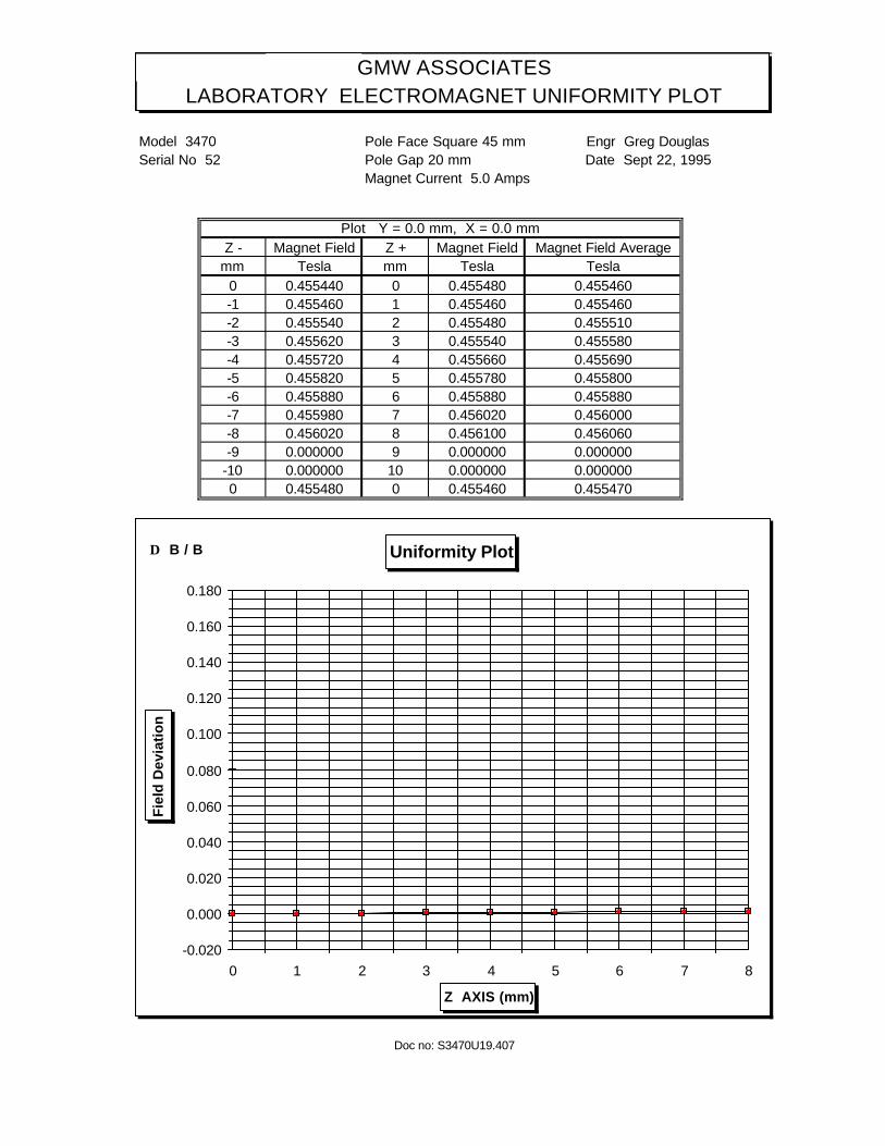
GMW ASSOCIATESLABORATORY ELECTROMAGNET UNIFORMITY PLOT
Model 3470 Pole Face Square 45 mm Engr Greg DouglasSerial No 52 Pole Gap 20 mm Date Sept 22, 1995
Magnet Current 5.0 Amps
Plot Y = 0.0 mm, X = 0.0 mmZ - Magnet Field Z + Magnet Field Magnet Field Average
mm Tesla mm Tesla Tesla0 0.455440 0 0.455480 0.455460 0.000-1 0.455460 1 0.455460 0.455460 0.000-2 0.455540 2 0.455480 0.455510 0.000-3 0.455620 3 0.455540 0.455580 0.000-4 0.455720 4 0.455660 0.455690 0.001-5 0.455820 5 0.455780 0.455800 0.001-6 0.455880 6 0.455880 0.455880 0.001-7 0.455980 7 0.456020 0.456000 0.001-8 0.456020 8 0.456100 0.456060 0.001-9 0.000000 9 0.000000 0.000000 -1.000
-10 0.000000 10 0.000000 0.000000 -1.0000 0.455480 0 0.455460 0.455470
Doc no: S3470U19.407
Uniformity Plot
-0.020
0.000
0.020
0.040
0.060
0.080
0.100
0.120
0.140
0.160
0.180
0 1 2 3 4 5 6 7 8
Z AXIS (mm)
Fie
ld D
evia
tio
n
∆ B / B

Section 10
DRAWINGS


Related Documents