USER'S HANDBOOK Model 1362/S/MT VXIbus Card DMM

Welcome message from author
This document is posted to help you gain knowledge. Please leave a comment to let me know what you think about it! Share it to your friends and learn new things together.
Transcript

USER'S HANDBOOK
Model 1362/S/MTVXIbus Card DMM
User's HandbookFor
The Model 1362/S/MTVXIbus Card DMM
850255 Issue 5.0 (October 2002)
© 2002 Wavetek Ltd
is a US registered trademark of Wavetek Corporation.
For any assistance contact your nearest Wavetek Sales and Service Center.Addresses can be found at the back of this handbook.
Due to our policy of continuously updating our products, this handbook may contain minordifferences in specification, components and circuit design to the instrument actually supplied.Amendment sheets precisely matched to your instrument serial number are available on request.
ISO 9002Wavetek Ltd
CERTIFICATENo. FM 29700

Wavetek Corporation reserves the right to amend specifications without notice.
Wavetek CorporationStandard Warranty Policy
Wavetek warrants that all Products manufactured or procured by Wavetek conform to Wavetek's publishedspecifications and are free from defects in materials and workmanship for a period of one (1) year from the dateof delivery to the original Buyer, when used under normal operating conditions and within the service conditionsfor which they were designed. This warranty is not transferrable and does not apply to used or demonstrationproducts.
The obligation of Wavetek arising from a Warranty claim shall be limited to repairing, or at its option, replacingwithout charge, any assembly or component (except batteries) which in Wavetek's sole opinion proves to bedefective within the scope of the Warranty. In the event Wavetek is not able to modify, repair or replacenonconforming defective parts or components to a condition as warranted within a reasonable time after receiptthereof, Buyers shall receive credit in the amount of the original invoiced price of the product.
Wavetek must be notified in writing of the defect or nonconformity within the Warranty period and the affectedProduct returned to Wavetek's factory, designated Service Provider, or Authorized Service Center within thirty(30) days after discovery of such defect or nonconformity. Buyer shall prepay shipping charges and insurance forProducts returned to Wavetek or its designated Service Provider for warranty service. Wavetek or its designatedService Provider shall pay costs for return of Products to Buyer.
Wavetek shall have no responsibility for any defect or damage caused by improper storage, improper installation,unauthorized modification, misuse, neglect, inadequate maintenance, accident or for any Product which has beenrepaired or altered by anyone other than Wavetek or its authorized representative or not in accordance withinstructions furnished by Wavetek.
The Warranty described above is Buyer's sole and exclusive remedy and no other warranty, whether written or oral,expressed or implied by statute or course of dealing shall apply. Wavetek specifically disclaims the impliedwarranties of merchantability and fitness for a particular purpose. No statement, representation, agreement, orunderstanding, oral or written, made by an agent, distributor, or employee of Wavetek, which is not contained inthe foregoing Warranty will be binding upon Wavetek, unless made in writing and executed by an authorizedrepresentative of Wavetek. Under no circumstances shall Wavetek be liable for any direct, indirect, special,incidental, or consequential damages, expenses, or losses, including loss of profits, based on contract, tort, or anyother legal theory.
April 1, 1994

1362 Users Handbook - Contents
SAFETY ISSUESREAD THIS ENTIRE SECTION THOROUGHLY BEFORE ATTEMPTING TO INSTALL, OPERATEOR SERVICE THE MODEL 1362/S/MT VXIbus CARD DMM
Section 1 Introduction 1-1Standard and Optional Measurement Facilities ..................................... 1-2
Section 2 Installation 2-1Logical Address Switch Configuration .................................................... 2-2Interrupt Acknowledge Daisy Chain ....................................................... 2-2Fitting the 1362 into the Subrack ............................................................ 2-2Removal from the Subrack ..................................................................... 2-250Hz/60Hz/400/Hz Line Frequency Configuration ................................. 2-3Front Panel Connections ........................................................................ 2-3
Section 3 1362 VXI Low Level Interface 3-1VXI Registers ......................................................................................... 3-2Message Based Specifics ...................................................................... 3-4VXI to DMM Communications Cycle ...................................................... 3-6Word Serial Protocol Commands ........................................................... 3-8
Section 4 1362S SCPI Language 4-1SCPI Programming Language ............................................................... 4-2Message Exchange ................................................................................ 4-3Service Request (RQS) .......................................................................... 4-4Retrieval of Device Status Information - Introduction ............................. 4-51362 Status Reporting - Detail ............................................................... 4-71362 SCPI Language - Commands and Syntax ................................... 4-11Appendix A to Section 4: 1362 SCPI — ................................................ 4-A1
Command Summary ................................................................... 4-A2Error Codes and Messages ........................................................ 4-A3*RST (Reset) Conditions ............................................................. 4-A4Trigger Combinations .................................................................. 4-A5Trigger Timing Information .......................................................... 4-A5
Section 5 1362 Native Language - IEEE-488.2 Command Syntax 5-1IEEE-488.2 Programming Language ..................................................... 5-2IEEE-488.2 Syntax Diagrams in this Section ......................................... 5-2Message Exchange ................................................................................ 5-6Service Request (RQS) .......................................................................... 5-7Retrieval of Device Status Information - Introduction ............................. 5-81362 Status Reporting - Detail ............................................................... 5-101362 Native Language - IEEE-488.2 Command Syntax Diagrams ........ 5-14Appendix A to Section 5: 1362 Device Settings at Power On ................ 5-A2
Section 6 1362MT - Guide to CIIL Command Language 6-1Power On Default Settings ..................................................................... 6-2Control Interface Intermediate Language ............................................... 6-2
Section 7 1362 Specifications and Specification Verification 7-1Specifications ......................................................................................... 7-2Specification Verification ........................................................................ 7-4
Section 8 1362 Routine CalibrationIntroduction ............................................................................................. 8-2Preparation ............................................................................................. 8-2Procedures ............................................................................................. 8-3
Section 9 and Section 10 are not applicable
Section 11 Servicing Diagrams 11-1See the Contents List at the Start of Section 11
Section 12 1362 Component Lists 12-1See the Contents List at the Start of Section 12

SAFETY ISSUESREAD THIS ENTIRE SECTION THOROUGHLY BEFORE ATTEMPTING TO INSTALL, OPERATE OR SERVICE THE MODEL 1362/S/MTVXIbus CARD DMM
General Safety Summary
This instrument has been designed and tested in accordance withthe British and European standard publication EN61010:1993/A2:1995, and has been supplied in a safe condition.
This manual contains information and warnings that must beobserved to keep the instrument in a safe condition and ensuresafe operation. Operation or service in conditions or in a mannerother than specified could compromise safety. For the correctand safe use of this instrument, operating and service personnelmust follow generally accepted safety procedures, in addition tothe safety precautions specified.
To avoid injury or fire hazard, do not switch on the instrumentif it is damaged or suspected to be faulty. Do not use theinstrument in damp, wet, condensing, dusty, or explosive gasenvironments.
Whenever it is likely that safety protection has been impaired,make the instrument inoperative and secure it against anyinintended operation. Inform qualified maintenance or repairpersonnel. Safety protection is likely to be impaired if, forexample, the instrument shows visible damage, or fails tooperate normally.
Explanation of safety-relatedsymbols and terms
DANGER electric shock riskThe product is marked with this symbol to indicatethat hazardous voltages (>30 VDC or AC peak)may be present.
CAUTION refer to documentationThe product is marked with this symbol when theuser must refer to the instruction manual.
Earth (Ground) terminalFunctional Earth (Ground) only - must not be usedas a Protective Earth.
Warnings and Cautions
WARNING WARNING STATEMENTS IDENTIFYCONDITIONS OR PRACTICES THATCOULD RESULT IN INJURY OR DEATH.
CAUTION CAUTION STATEMENTS IDENTIFYCONDITIONS OR PRACTICES THATCOULD RESULT IN DAMAGE TO THISOR OTHER PROPERTY.
WARNING THIS INSTRUMENT CAN DELIVER ALETHAL ELECTRIC SHOCK. NEVERTOUCH ANY LEAD OR TERMINALUNLESS YOU ARE ABSOLUTELYCERTAIN THAT NO DANGEROUSVOLTAGE IS PRESENT. Installation Category I:
Measurement and/or guard terminals are designed for connectionat Installation (Overvoltage) Category I. To avoid electric shockor fire hazard, the instrument terminals must not be directlyconnected to the AC line power supply, or to any other voltageor current source that may (even temporarily) exceed theinstrument's peak ratings.
WARNING TO AVOID INJURY OR DEATH, DO NOTCONNECT OR DISCONNECT SIGNALLEADS WHILE THEY ARE CONNECTEDTO A HAZARDOUS VOLTAGE ORCURRENT SOURCE.
MAKE SURE THAT SIGNAL LEADS AREIN A SAFE CONDITION BEFORE YOUHANDLE THEM ANY WAY.
THE INSTRUMENT MUST BE POWEREDWHEN ANY SIGNAL IS PRESENT AT ITSINPUT TERMINALS.
continued overleaf
To avoid electric shock hazard, make signal connections to theinstrument after making the protective ground connection.Remove signal connections before removing the protectiveground connection, i.e. the power cable must be connectedwhenever signal leads are connected.
Protective Earth (Ground)The instrument must be operated with a permanent ProtectiveEarth/Ground connection to the VXIbus mainframe's powersupply.
WARNING ANY INTERRUPTION OF THEPROTECTIVE GROUND CONDUCTOR TOTHE VXI MAINFRAME IS LIKELY TOMAKE THE MAINFRAME AND ALLMODULES DANGEROUS TO USE.

Do Not Operate Without Covers
To avoid electric shock or fire hazard, do not operate theinstrument with its covers removed. The covers protect usersfrom live parts, and unless otherwise stated, must only beremoved by qualified service personnel for maintenance andrepair purposes.
WARNING
REMOVING THE COVERS MAY EXPOSEVOLTAGES IN EXCESS OF 1.5KV PEAK(MORE UNDER FAULT CONDITIONS).
Safe Operating Conditions
Only operate the instrument within the manufacturer's specifiedoperating conditions. Specification examples that must beconsidered include:
ambient temperatureambient humiditypower supply voltage & frequencymaximum terminal voltages or currentsaltitudeambient pollution level (Pollution Degree 2)exposure to shock and vibration
To avoid electric shock or fire hazard, do not apply to orsubject the instrument to any condition that is outside specifiedrange. See Section 7 of this manual for detailed instrumentspecifications and operating conditions.
CAUTIONCONSIDER DIRECT SUNLIGHT,RADIATORS AND OTHER HEATSOURCES WHEN ASSESSING AMBIENTTEMPERATURE.
CAUTIONBEFORE CONNECTING THEINSTRUMENT TO THE SUPPLY, MAKESURE THAT THE REAR PANEL ACSUPPLY VOLTAGE CONNECTOR IS SETTO THE CORRECT VOLTAGE ANDTHAT THE CORRECT FUSES AREFITTED.
Maintenance and Repair
Observe all applicable local and/or national safety regulationsand rules while performing any work. First disconnect theinstrument from all signal sources, then from the AC linesupply before removing any cover. Any adjustment, partsreplacement, maintenance or repair should be carried out onlyby the manufacturer's authorized technical personnel.
WARNINGFOR PROTECTION AGAINST INJURYAND FIRE HAZARD, USE ONLYMANUFACTURER SUPPLIED PARTSTHAT ARE RELEVANT TO SAFETY.PERFORM SAFETY TESTS AFTERREPLACING ANY PART THAT ISRELEVANT TO SAFETY.
Moving and Cleaning
First disconnect the instrument from all signal sources, thendisconnect the VXI mainframe from the AC line supply beforemoving or cleaning.Use only a damp, lint-free cloth to cleanfascia and case parts.
Observe any additional safety instructionsor warnings given in this manual.

SECTION 1INTRODUCTION
1-1
Section 1 - Introduction
1-2
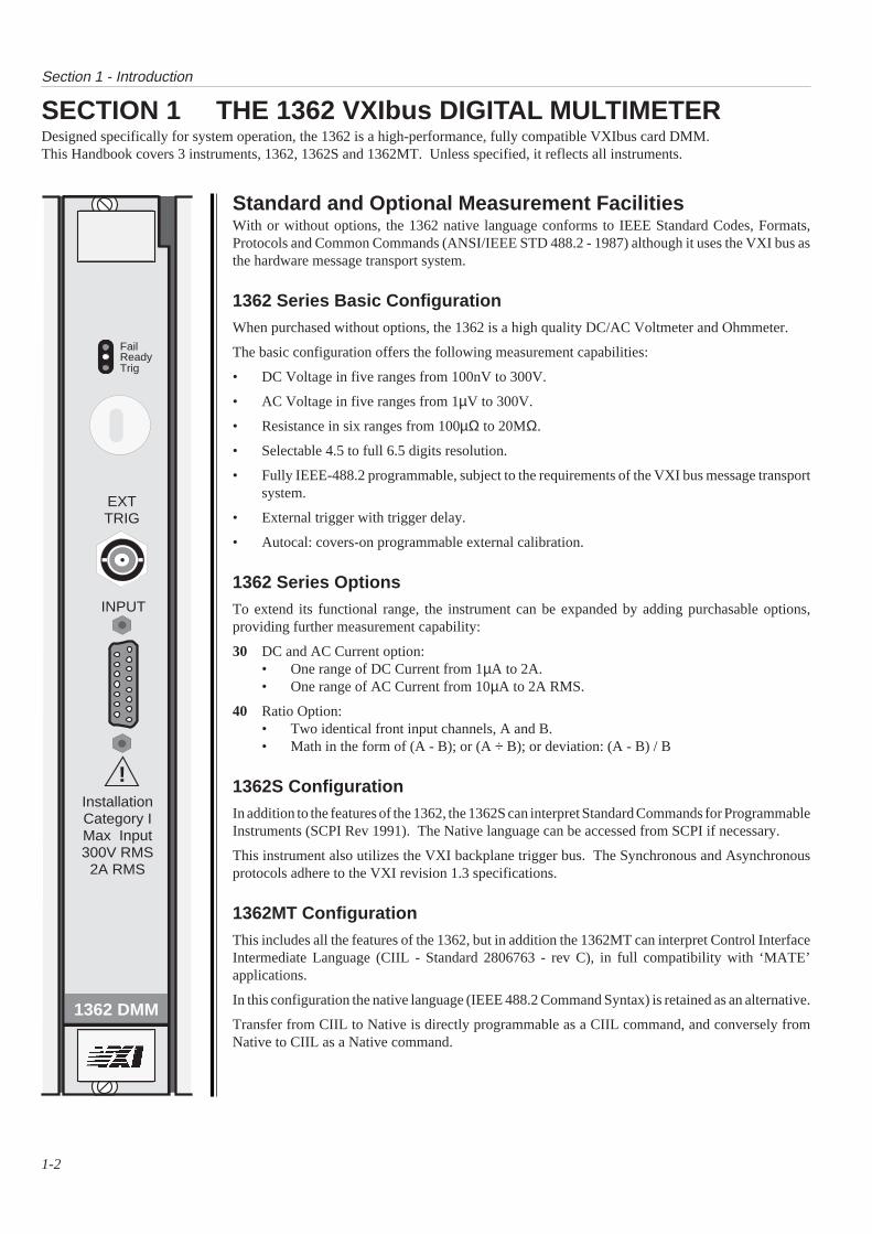
SECTION 1 THE 1362 VXIbus DIGITAL MULTIMETERDesigned specifically for system operation, the 1362 is a high-performance, fully compatible VXIbus card DMM.This Handbook covers 3 instruments, 1362, 1362S and 1362MT. Unless specified, it reflects all instruments.
Standard and Optional Measurement FacilitiesWith or without options, the 1362 native language conforms to IEEE Standard Codes, Formats,Protocols and Common Commands (ANSI/IEEE STD 488.2 - 1987) although it uses the VXI bus asthe hardware message transport system.
1362 Series Basic ConfigurationWhen purchased without options, the 1362 is a high quality DC/AC Voltmeter and Ohmmeter.
The basic configuration offers the following measurement capabilities:
• DC Voltage in five ranges from 100nV to 300V.
• AC Voltage in five ranges from 1µV to 300V.
• Resistance in six ranges from 100µΩ to 20MΩ.
• Selectable 4.5 to full 6.5 digits resolution.
• Fully IEEE-488.2 programmable, subject to the requirements of the VXI bus message transportsystem.
• External trigger with trigger delay.
• Autocal: covers-on programmable external calibration.
1362 Series OptionsTo extend its functional range, the instrument can be expanded by adding purchasable options,providing further measurement capability:
30 DC and AC Current option:• One range of DC Current from 1µA to 2A.• One range of AC Current from 10µA to 2A RMS.
40 Ratio Option:• Two identical front input channels, A and B.• Math in the form of (A - B); or (A ÷ B); or deviation: (A - B) / B
1362S ConfigurationIn addition to the features of the 1362, the 1362S can interpret Standard Commands for ProgrammableInstruments (SCPI Rev 1991). The Native language can be accessed from SCPI if necessary.
This instrument also utilizes the VXI backplane trigger bus. The Synchronous and Asynchronousprotocols adhere to the VXI revision 1.3 specifications.
1362MT ConfigurationThis includes all the features of the 1362, but in addition the 1362MT can interpret Control InterfaceIntermediate Language (CIIL - Standard 2806763 - rev C), in full compatibility with ‘MATE’applications.
In this configuration the native language (IEEE 488.2 Command Syntax) is retained as an alternative.
Transfer from CIIL to Native is directly programmable as a CIIL command, and conversely fromNative to CIIL as a Native command.
Fail
TrigReady
InstallationCategory IMax Input300V RMS2A RMS
INPUT
!
EXTTRIG
1362 DMM

Section 1 - Introduction
1-3
Safety Default Stateand Function ConfigurationsWhen the instrument power is switched on, all functions areforced into a safety default state. Once a function is configured toa required state it remains in that state, regardless of subsequentconfigurations in other functions, until either the state is changedor the instrument power is switched off.
CalibrationAutocalThe 1362 is an ‘Autocal’ instrument, providing full externalcalibration of all ranges and functions via the VXIbus, so that it isnot necessary to remove any covers. Calibration commands canbe programmed in SCPI and native language, but not in CIIL.
Periodically, the DMM should be electronically calibrated againstexternal inputs from traceable standards. The difference betweenthe DMM’s reading and the value of the external calibrationsource is used to derive calibration constants, which are stored bythe instrument in non-volatile memory. The 1362 assumes thatnominal values are used, unless informed of deviations fromnominal by user-commands via the VXI bus.
Subsequently, when in normal use, the DMM calculates andapplies a correction from the most-recently stored externalcalibration constants for the parameters of the measurement inprogress. Thus each reading taken by the DMM receives anindividual correction derived from the latest calibration.
Calibration SecurityAccidental or unauthorized use of calibration facilities is preventedby a screwdriver-operated switch in a hole on the front panel. Inaddition, an enabling command must be used in order to entercalibration mode. For Native language this is 'CAL ON' (Section5, page 5-29); and for SCPI language in the 1362S, it is'CALibration SECure ' (Section 4, page 4-13).
Calibration RoutinesThe Routine Autocal procedures are given in Section 8 of thishandbook.
Message ReadoutGenerally, the offered selections reflect the availability of facilities,incompatible combinations being excluded. Nevertheless, the1362 outputs information to the user such as unsuitable attemptsat configuration, test failures and some other conditions whichwould need to be reported to an authorized service center.
ProgrammingData can be input via the VXI bus to set up measurements withfacilities for:
• selecting a suitable range for measurement of an expectedvalue;
• introducing user-defined trigger delays;
• setting the number of readings-per-block to be taken when inBLOCK mode;
• recalling a number of readings (sub-block) from a storedblock;
• setting non-nominal targets for requested calibrations;
• performing a nominated individual test from the range oftests activated in sequence during a ‘Self Test’.
Operation within the parameters of each function or facility isprogrammed by selection from the available codes.
Full details are given in Sections 4, 5 and 6.
Self TestStandard codes are used to activate the instrument’s internal SelfTest sequence. These can be found in Sections 4 to 6.

this page deliberately left blank

SECTION 2INSTALLATION
2-1
Section 2 - Installation
2-2
SECTION 2 INSTALLATION
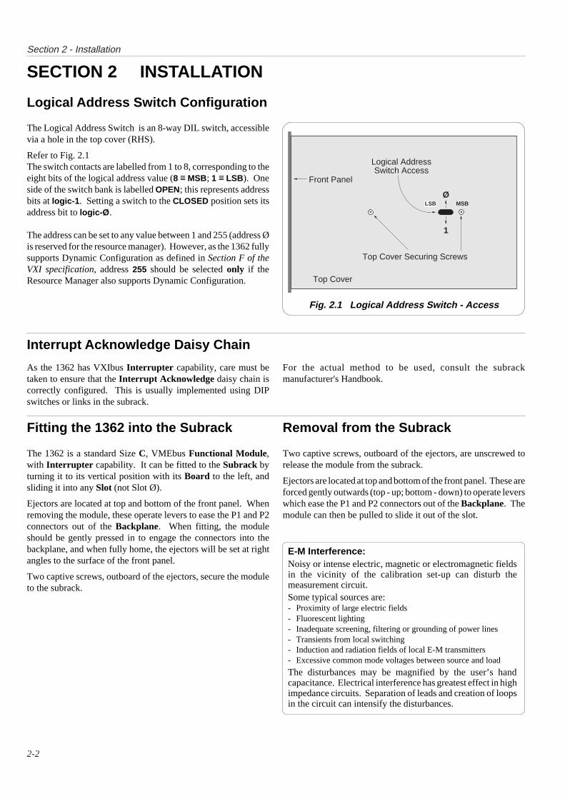
Logical Address Switch Configuration
Logical AddressSwitch Access
LSB
Top Cover Securing Screws
Front Panel
MSBØ
1
Top Cover
Fig. 2.1 Logical Address Switch - Access
Interrupt Acknowledge Daisy Chain
As the 1362 has VXIbus Interrupter capability, care must betaken to ensure that the Interrupt Acknowledge daisy chain iscorrectly configured. This is usually implemented using DIPswitches or links in the subrack.
For the actual method to be used, consult the subrackmanufacturer's Handbook.
Fitting the 1362 into the Subrack
The 1362 is a standard Size C, VMEbus Functional Module,with Interrupter capability. It can be fitted to the Subrack byturning it to its vertical position with its Board to the left, andsliding it into any Slot (not Slot Ø).
Ejectors are located at top and bottom of the front panel. Whenremoving the module, these operate levers to ease the P1 and P2connectors out of the Backplane. When fitting, the moduleshould be gently pressed in to engage the connectors into thebackplane, and when fully home, the ejectors will be set at rightangles to the surface of the front panel.
Two captive screws, outboard of the ejectors, secure the moduleto the subrack.
Removal from the Subrack
Two captive screws, outboard of the ejectors, are unscrewed torelease the module from the subrack.
Ejectors are located at top and bottom of the front panel. These areforced gently outwards (top - up; bottom - down) to operate leverswhich ease the P1 and P2 connectors out of the Backplane. Themodule can then be pulled to slide it out of the slot.
The Logical Address Switch is an 8-way DIL switch, accessiblevia a hole in the top cover (RHS).
Refer to Fig. 2.1The switch contacts are labelled from 1 to 8, corresponding to theeight bits of the logical address value (8 ≡ MSB; 1 ≡ LSB). Oneside of the switch bank is labelled OPEN; this represents addressbits at logic-1 . Setting a switch to the CLOSED position sets itsaddress bit to logic-Ø .
The address can be set to any value between 1 and 255 (address Øis reserved for the resource manager). However, as the 1362 fullysupports Dynamic Configuration as defined in Section F of theVXI specification, address 255 should be selected only if theResource Manager also supports Dynamic Configuration.
E-M Interference:Noisy or intense electric, magnetic or electromagnetic fieldsin the vicinity of the calibration set-up can disturb themeasurement circuit.Some typical sources are:- Proximity of large electric fields- Fluorescent lighting- Inadequate screening, filtering or grounding of power lines- Transients from local switching- Induction and radiation fields of local E-M transmitters- Excessive common mode voltages between source and load
The disturbances may be magnified by the user’s handcapacitance. Electrical interference has greatest effect in highimpedance circuits. Separation of leads and creation of loopsin the circuit can intensify the disturbances.
Section 2 - Installation
2-3
50Hz/60Hz/400Hz Line Frequency Configuration
Line Frequency Programming
To obtain optimum performance from the A-D converter it isnecessary to adapt its configuration to the line frequency in use.The adaptation is performed by remote programming.
The 1362 has been calibrated to your local line frequency. Thesyntax used to reset or query the line frequency depends on themodel type.
Associated SCPI Commands
The following syntax are associated with line setting and query(Refer to Section 4; page 4-32).
SENse:LFRequency <numeric_value>
Example, 50Hz, 60Hz or 400Hz
SENse:LFRequency? Queries the current line setting.
CALibration:SLFRequency? Saves the current linefrequency setting to non-volatile memory. This setting issubsequently used as the power up default.
Associated Native Commands
The following syntax are associated with line setting and query(Refer to Section 5; page 5-32).
LINE <Nrf> Selects the line frequency.
LINE? Recalls the line frequency to which the instrument iscurrently adapted.
STLN? Saves the current line frequency setting to non volatilememory. This setting is subsequently used as the power updefault.
Further information about the programming syntax is detailed inSections 4 and 5.
No Associated CIIL Command
There are no implemented CIIL commands associated with linesetting and query. Line frequency configuration must be set inNative Language.(Implemented CIIL commands are given in Section 6.)
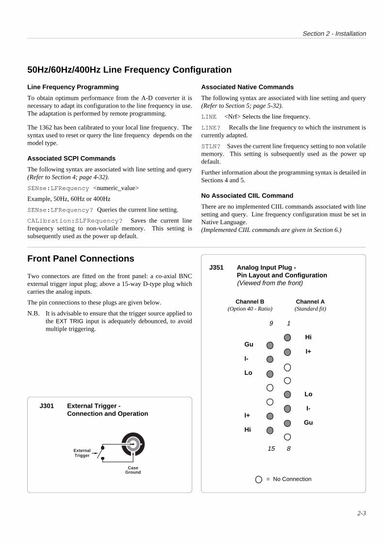
Front Panel Connections
Two connectors are fitted on the front panel: a co-axial BNCexternal trigger input plug; above a 15-way D-type plug whichcarries the analog inputs.
The pin connections to these plugs are given below.
N.B. It is advisable to ensure that the trigger source applied tothe EXT TRIG input is adequately debounced, to avoidmultiple triggering.
J351 Analog Input Plug -Pin Layout and Configuration(Viewed from the front)
HiGu
I+I-
Lo
Lo
I-I+
GuHi
9 1
15 8
Channel B(Option 40 - Ratio)
Channel A(Standard fit)
= No Connection
J301 External Trigger -Connection and Operation
CaseGround
ExternalTrigger
AAAAAAAA
AAAAAA
A

this page deliberately left blank

SECTION 31362 VXI LOW LEVEL INTERFACE
3-1
3-2
Section 3 - VXI Low Level Interface
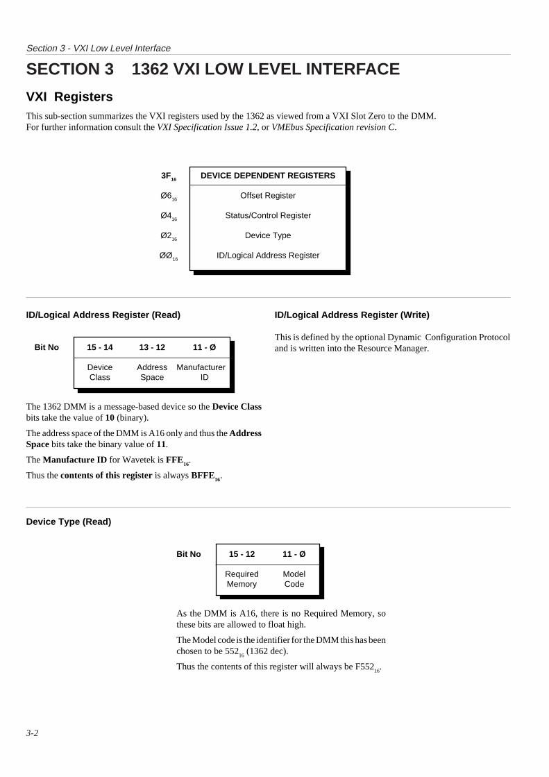
As the DMM is A16, there is no Required Memory, sothese bits are allowed to float high.
The Model code is the identifier for the DMM this has beenchosen to be 552
16 (1362 dec).
Thus the contents of this register will always be F55216
.
DEVICE DEPENDENT REGISTERS
Offset Register
Status/Control Register
Device Type
ID/Logical Address Register
3F16
Ø616
Ø416
Ø216
ØØ16
Device Type (Read)
The 1362 DMM is a message-based device so the Device Classbits take the value of 10 (binary).
The address space of the DMM is A16 only and thus the AddressSpace bits take the binary value of 11.
The Manufacture ID for Wavetek is FFE16
.
Thus the contents of this register is always BFFE16
.
ID/Logical Address Register (Write)
This is defined by the optional Dynamic Configuration Protocoland is written into the Resource Manager.
SECTION 3 1362 VXI LOW LEVEL INTERFACE
VXI RegistersThis sub-section summarizes the VXI registers used by the 1362 as viewed from a VXI Slot Zero to the DMM.For further information consult the VXI Specification Issue 1.2, or VMEbus Specification revision C.
ID/Logical Address Register (Read)
Bit No 15 - 14 13 - 12 11 - Ø
Device Address ManufacturerClass Space ID
Bit No 15 - 12 11 - Ø
Required ModelMemory Code
3-3
Section 3 - VXI Low Level Interface
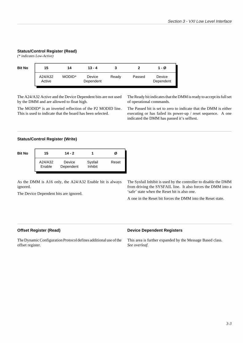
Status/Control Register (Read)(* indicates Low-Active)
The A24/A32 Active and the Device Dependent bits are not usedby the DMM and are allowed to float high.
The MODID* is an inverted reflection of the P2 MODID line.This is used to indicate that the board has been selected.
The Ready bit indicates that the DMM is ready to accept its full setof operational commands.
The Passed bit is set to zero to indicate that the DMM is eitherexecuting or has failed its power-up / reset sequence. A oneindicated the DMM has passed it’s selftest.
Status/Control Register (Write)
Bit No 15 14 13 - 4 3 2 1 - Ø
A24/A32 MODID* Device Ready Passed DeviceActive Dependent Dependent
Bit No 15 14 - 2 1 Ø
A24/A32 Device Sysfail ResetEnable Dependent Inhibit
As the DMM is A16 only, the A24/A32 Enable bit is alwaysignored.
The Device Dependent bits are ignored.
The Sysfail Inhibit is used by the controller to disable the DMMfrom driving the SYSFAIL line. It also forces the DMM into a‘safe’ state when the Reset bit is also one.
A one in the Reset bit forces the DMM into the Reset state.
Device Dependent Registers
This area is further expanded by the Message Based class.See overleaf.
Offset Register (Read)
The Dynamic Configuration Protocol defines additional use of theoffset register.

3-4
Section 3 - VXI Low Level Interface
Message Based SpecificsThe VXI specification allocates further registers for message based devices in the Device Dependent area shown above.This gives:
DEVICE DEPENDENT REGISTERS
Reserved
A32 Pointer
A24 Pointers
Data Low
Data High
Response/Data Extended
Protocol/Signal Register
CONFIGURATION REGISTERS
3F16
1F16
1416
1Ø16
ØE16
ØC16
ØA16
Ø816
ØØ16
The Configuration Registers are described earlier on pages 3-2 and 3-3.
Protocol/Signal Register (Read)(* indicates Low-Active)
Bit No 15 14 13 12 11 1Ø 9 - 4 3 - Ø
CMDR* Signal Master Interrupter FHS* Shared RESERVED DeviceReg* Mem* Dependent
In the above, the DMM is not a commander, has no signalregister, is not a bus master, does not support Fast HandShake and does not use shared memory. Thus all of thesebits float to one. The RESERVED and Device Dependentbits are not used and also float to one.
It is however an interrupter, and this is indicated by theInterrupted bit being one. Thus the entire register is alwaysread by VXI as FFFF
16.
Protocol/Signal Register (Write)
The signal Register in the DMM is not implemented.
3-5
Section 3 - VXI Low Level Interface
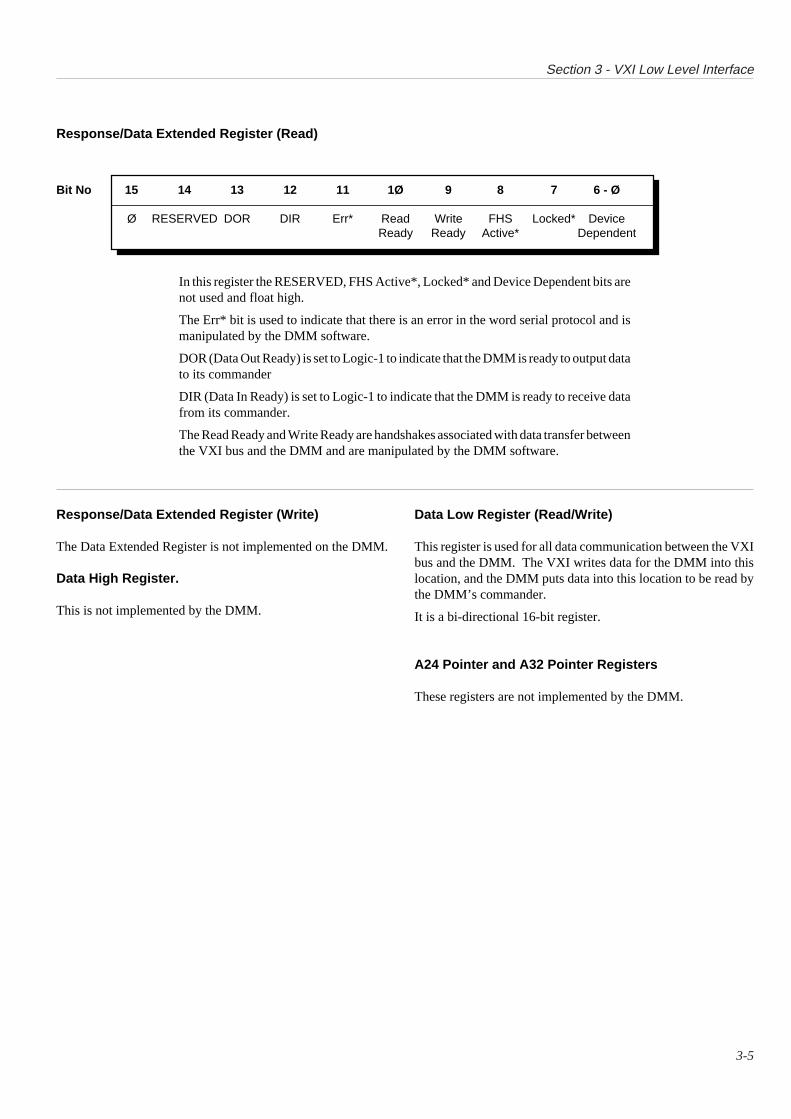
In this register the RESERVED, FHS Active*, Locked* and Device Dependent bits arenot used and float high.
The Err* bit is used to indicate that there is an error in the word serial protocol and ismanipulated by the DMM software.
DOR (Data Out Ready) is set to Logic-1 to indicate that the DMM is ready to output datato its commander
DIR (Data In Ready) is set to Logic-1 to indicate that the DMM is ready to receive datafrom its commander.
The Read Ready and Write Ready are handshakes associated with data transfer betweenthe VXI bus and the DMM and are manipulated by the DMM software.
Response/Data Extended Register (Read)
Bit No 15 14 13 12 11 1Ø 9 8 7 6 - Ø
Ø RESERVED DOR DIR Err* Read Write FHS Locked* DeviceReady Ready Active* Dependent
Response/Data Extended Register (Write)
The Data Extended Register is not implemented on the DMM.
Data High Register.
This is not implemented by the DMM.
Data Low Register (Read/Write)
This register is used for all data communication between the VXIbus and the DMM. The VXI writes data for the DMM into thislocation, and the DMM puts data into this location to be read bythe DMM’s commander.
It is a bi-directional 16-bit register.
A24 Pointer and A32 Pointer Registers
These registers are not implemented by the DMM.
3-6
Section 3 - VXI Low Level Interface
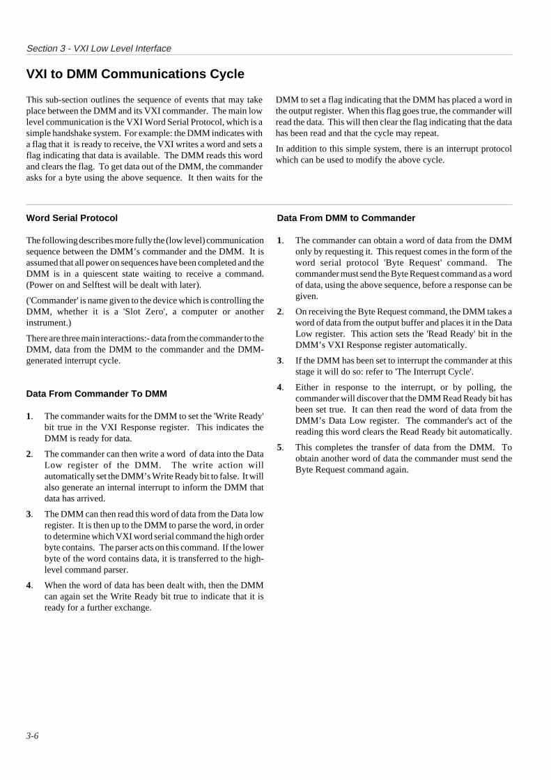
VXI to DMM Communications Cycle
This sub-section outlines the sequence of events that may takeplace between the DMM and its VXI commander. The main lowlevel communication is the VXI Word Serial Protocol, which is asimple handshake system. For example: the DMM indicates witha flag that it is ready to receive, the VXI writes a word and sets aflag indicating that data is available. The DMM reads this wordand clears the flag. To get data out of the DMM, the commanderasks for a byte using the above sequence. It then waits for the
DMM to set a flag indicating that the DMM has placed a word inthe output register. When this flag goes true, the commander willread the data. This will then clear the flag indicating that the datahas been read and that the cycle may repeat.
In addition to this simple system, there is an interrupt protocolwhich can be used to modify the above cycle.
Word Serial Protocol
The following describes more fully the (low level) communicationsequence between the DMM’s commander and the DMM. It isassumed that all power on sequences have been completed and theDMM is in a quiescent state waiting to receive a command.(Power on and Selftest will be dealt with later).
('Commander' is name given to the device which is controlling theDMM, whether it is a 'Slot Zero', a computer or anotherinstrument.)
There are three main interactions:- data from the commander to theDMM, data from the DMM to the commander and the DMM-generated interrupt cycle.
Data From Commander To DMM
1. The commander waits for the DMM to set the 'Write Ready'bit true in the VXI Response register. This indicates theDMM is ready for data.
2. The commander can then write a word of data into the DataLow register of the DMM. The write action willautomatically set the DMM’s Write Ready bit to false. It willalso generate an internal interrupt to inform the DMM thatdata has arrived.
3. The DMM can then read this word of data from the Data lowregister. It is then up to the DMM to parse the word, in orderto determine which VXI word serial command the high orderbyte contains. The parser acts on this command. If the lowerbyte of the word contains data, it is transferred to the high-level command parser.
4. When the word of data has been dealt with, then the DMMcan again set the Write Ready bit true to indicate that it isready for a further exchange.
Data From DMM to Commander
1. The commander can obtain a word of data from the DMMonly by requesting it. This request comes in the form of theword serial protocol 'Byte Request' command. Thecommander must send the Byte Request command as a wordof data, using the above sequence, before a response can begiven.
2. On receiving the Byte Request command, the DMM takes aword of data from the output buffer and places it in the DataLow register. This action sets the 'Read Ready' bit in theDMM’s VXI Response register automatically.
3. If the DMM has been set to interrupt the commander at thisstage it will do so: refer to 'The Interrupt Cycle'.
4. Either in response to the interrupt, or by polling, thecommander will discover that the DMM Read Ready bit hasbeen set true. It can then read the word of data from theDMM’s Data Low register. The commander's act of thereading this word clears the Read Ready bit automatically.
5. This completes the transfer of data from the DMM. Toobtain another word of data the commander must send theByte Request command again.
3-7
Section 3 - VXI Low Level Interface
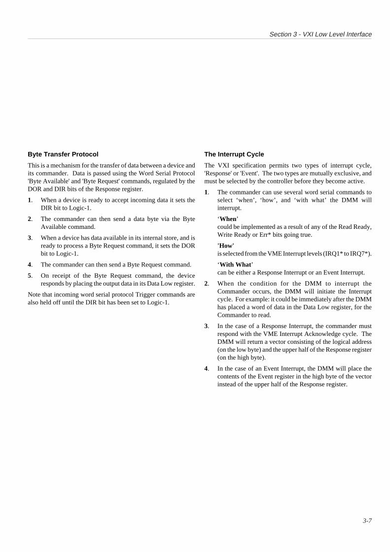
Byte Transfer Protocol
This is a mechanism for the transfer of data between a device andits commander. Data is passed using the Word Serial Protocol'Byte Available' and 'Byte Request' commands, regulated by theDOR and DIR bits of the Response register.
1. When a device is ready to accept incoming data it sets theDIR bit to Logic-1.
2. The commander can then send a data byte via the ByteAvailable command.
3. When a device has data available in its internal store, and isready to process a Byte Request command, it sets the DORbit to Logic-1.
4. The commander can then send a Byte Request command.
5. On receipt of the Byte Request command, the deviceresponds by placing the output data in its Data Low register.
Note that incoming word serial protocol Trigger commands arealso held off until the DIR bit has been set to Logic-1.
The Interrupt Cycle
The VXI specification permits two types of interrupt cycle,'Response' or 'Event'. The two types are mutually exclusive, andmust be selected by the controller before they become active.
1. The commander can use several word serial commands toselect ‘when’, ‘how’, and ‘with what’ the DMM willinterrupt.
‘When’could be implemented as a result of any of the Read Ready,Write Ready or Err* bits going true.
'How'is selected from the VME Interrupt levels (IRQ1* to IRQ7*).
‘With What ’can be either a Response Interrupt or an Event Interrupt.
2. When the condition for the DMM to interrupt theCommander occurs, the DMM will initiate the Interruptcycle. For example: it could be immediately after the DMMhas placed a word of data in the Data Low register, for theCommander to read.
3. In the case of a Response Interrupt, the commander mustrespond with the VME Interrupt Acknowledge cycle. TheDMM will return a vector consisting of the logical address(on the low byte) and the upper half of the Response register(on the high byte).
4. In the case of an Event Interrupt, the DMM will place thecontents of the Event register in the high byte of the vectorinstead of the upper half of the Response register.

Section 3 - VXI Low Level Interface
3-8
Word Serial Protocol CommandsThe VXI specification defines a series of commands that are used to configure, and communicate with, a device. These are all low levelsingle word commands sent, and responses received, via VXI word serial protocol.The following is the subset of commands implemented by the DMM:
(Note: The Code values and responses given apply only to the 1362 DMM and can vary for other devices)
Abort Normal Operation
The Abort Normal Operation command is used to cause the DMM to cease normal operation. On receipt of the command the DMMreturns to default configuration, aborting all operations. The DMM will then be in a generally inactive state and will be ready to acceptcommands.
The syntax of the Abort Normal Operation command is defined in the following table.
15 14 13 12 11 10 9 8 7 6 5 4 3 2 1 0
1 1 0 0 1 0 0 0 1 1 1 1 1 1 1 1
When the abort operation has completed (the DMM is in the aborted state), response data is placed in the Data Low register in thefollowing format:
15 14 13 12 11 10 9 8 7 6 5 4 3 2 1 0
1 1 1 1 1 1 1 1 1 1 1 1 1 1 1 0
Assign Interrupter Line
The Assign Interrupter Line is used to assign a VMEbus IRQ line to the DMM. The syntax of this command is defined in the followingtable.
15 14 13 12 11 10 9 8 7 6 5 4 3 2 1 0
1 0 1 0 1 0 1 0 X Int_ID X Line
• X: Don’t care. The value written to this bit has no effect.
• Int_ID: This is a unique identifier of the particular Interrupter being assigned. It has a range of 1 to 7. As the DMM has onlyone interrupter, this should always take the value 1.
• Line: This is the VMEbus IRQ line number. A value of zero (016
) indicates that the Interrupter is to be disconnected.
When the assignment operation has completed, response data is placed in the Data Low register in the following format:
15 14 13 12 11 10 9 8 7 6 5 4 3 2 1 0
Status 1 1 1 1 1 1 1 1 1 1 1 0
• Status: This field indicates the execution state of the command. It may have the following values:
- F16
: The command successfully completed.- 7
16: Command failed - The Interrupter referenced in the Int_ID field is unknown to this device.
Section 3 - VXI Low Level Interface
3-9
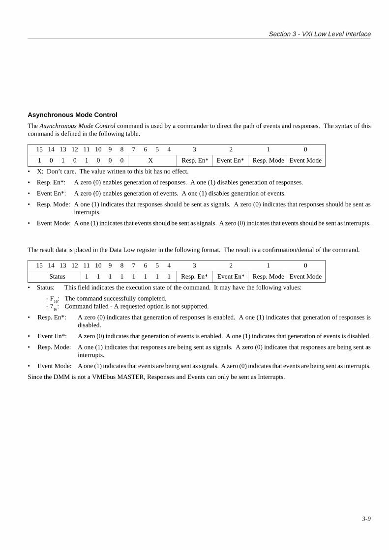
Asynchronous Mode Control
The Asynchronous Mode Control command is used by a commander to direct the path of events and responses. The syntax of thiscommand is defined in the following table.
15 14 13 12 11 10 9 8 7 6 5 4 3 2 1 0
1 0 1 0 1 0 0 0 X Resp. En* Event En* Resp. Mode Event Mode
• X: Don’t care. The value written to this bit has no effect.
• Resp. En*: A zero (0) enables generation of responses. A one (1) disables generation of responses.
• Event En*: A zero (0) enables generation of events. A one (1) disables generation of events.
• Resp. Mode: A one (1) indicates that responses should be sent as signals. A zero (0) indicates that responses should be sent asinterrupts.
• Event Mode: A one (1) indicates that events should be sent as signals. A zero (0) indicates that events should be sent as interrupts.
The result data is placed in the Data Low register in the following format. The result is a confirmation/denial of the command.
15 14 13 12 11 10 9 8 7 6 5 4 3 2 1 0
Status 1 1 1 1 1 1 1 1 Resp. En* Event En* Resp. Mode Event Mode
• Status: This field indicates the execution state of the command. It may have the following values:
- F16
: The command successfully completed.- 7
16: Command failed - A requested option is not supported.
• Resp. En*: A zero (0) indicates that generation of responses is enabled. A one (1) indicates that generation of responses isdisabled.
• Event En*: A zero (0) indicates that generation of events is enabled. A one (1) indicates that generation of events is disabled.
• Resp. Mode: A one (1) indicates that responses are being sent as signals. A zero (0) indicates that responses are being sent asinterrupts.
• Event Mode: A one (1) indicates that events are being sent as signals. A zero (0) indicates that events are being sent as interrupts.
Since the DMM is not a VMEbus MASTER, Responses and Events can only be sent as Interrupts.
Section 3 - VXI Low Level Interface
3-10
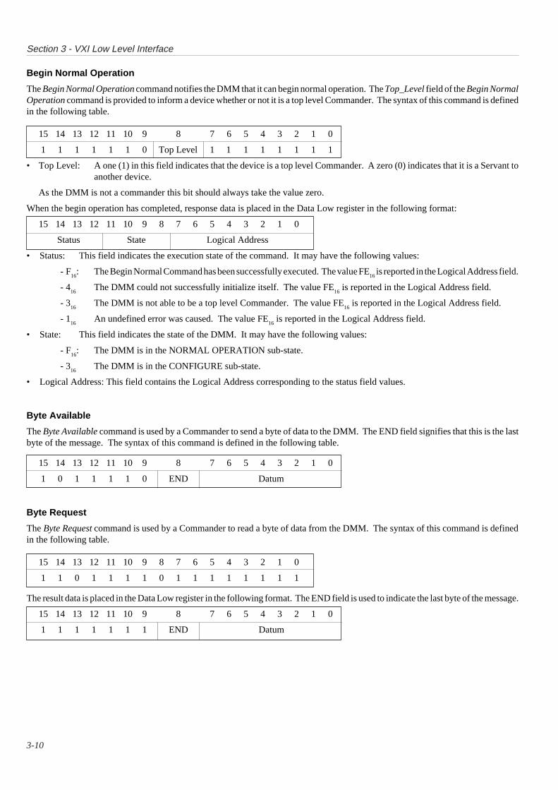
Begin Normal Operation
The Begin Normal Operation command notifies the DMM that it can begin normal operation. The Top_Level field of the Begin NormalOperation command is provided to inform a device whether or not it is a top level Commander. The syntax of this command is definedin the following table.
15 14 13 12 11 10 9 8 7 6 5 4 3 2 1 0
1 1 1 1 1 1 0 Top Level 1 1 1 1 1 1 1 1
• Top Level: A one (1) in this field indicates that the device is a top level Commander. A zero (0) indicates that it is a Servant toanother device.
As the DMM is not a commander this bit should always take the value zero.
When the begin operation has completed, response data is placed in the Data Low register in the following format:
15 14 13 12 11 10 9 8 7 6 5 4 3 2 1 0
Status State Logical Address
• Status: This field indicates the execution state of the command. It may have the following values:
- F16
: The Begin Normal Command has been successfully executed. The value FE16
is reported in the Logical Address field.
- 416
The DMM could not successfully initialize itself. The value FE16
is reported in the Logical Address field.
- 316
The DMM is not able to be a top level Commander. The value FE16
is reported in the Logical Address field.
- 116
An undefined error was caused. The value FE16
is reported in the Logical Address field.
• State: This field indicates the state of the DMM. It may have the following values:
- F16
: The DMM is in the NORMAL OPERATION sub-state.
- 316
The DMM is in the CONFIGURE sub-state.
• Logical Address: This field contains the Logical Address corresponding to the status field values.
Byte Available
The Byte Available command is used by a Commander to send a byte of data to the DMM. The END field signifies that this is the lastbyte of the message. The syntax of this command is defined in the following table.
15 14 13 12 11 10 9 8 7 6 5 4 3 2 1 0
1 0 1 1 1 1 0 END Datum
Byte Request
The Byte Request command is used by a Commander to read a byte of data from the DMM. The syntax of this command is definedin the following table.
15 14 13 12 11 10 9 8 7 6 5 4 3 2 1 0
1 1 0 1 1 1 1 0 1 1 1 1 1 1 1 1
The result data is placed in the Data Low register in the following format. The END field is used to indicate the last byte of the message.
15 14 13 12 11 10 9 8 7 6 5 4 3 2 1 0
1 1 1 1 1 1 1 END Datum

Section 3 - VXI Low Level Interface
3-11
Clear
The Clear command is used by a Commander to cause the DMM to clear the VXIbus interface and any pending operations. Any initiatedoperations in the DMM are undisturbed. The syntax of this command is defined in the following table.
15 14 13 12 11 10 9 8 7 6 5 4 3 2 1 0
1 1 1 1 1 1 1 1 1 1 1 1 1 1 1 1
Control Event
The Control Event command is used by a Commander to selectively enable the generation of events by the DMM. A one (1) in theenable field enables the generation of the specific event. A zero (0) in the enable field disables the generation of the specific event.The syntax of this command is defined in the following table.
15 14 13 12 11 10 9 8 7 6 5 4 3 2 1 0
1 0 1 0 1 1 1 1 Enable Event
• Event: These bits (6-0) are the identifying bits (14-8) of the event being enabled/disabled.
The following Events are supported:
Request True: This event is sent by the DMM when it requires service from its Commander. The syntax of this event is defined inthe following table.
15 14 13 12 11 10 9 8 7 6 5 4 3 2 1 0
1 1 1 1 1 1 0 1 Sender’s Logical Address
Request False: This event is sent by the DMM when it no longer requires service from its Commander. The syntax of this event isdefined in the following table.
15 14 13 12 11 10 9 8 7 6 5 4 3 2 1 0
1 1 1 1 1 1 0 0 Sender’s Logical Address
Device ResponseThe device returns the following data in the Data Low register:
15 14 13 12 11 10 9 8 7 6 5 4 3 2 1 0
Status 1 1 1 1 1 1 1 1 1 1 1 0
• Status: This field indicates the execution state of the command. It may have the following values:
- F16
: The command successfully completed.- 7
16: Command failed - The event referenced is not generated by this device.
Section 3 - VXI Low Level Interface
3-12
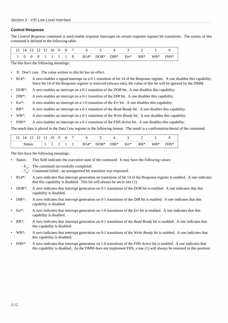
Control Response
The Control Response command is used enable response interrupts on certain response register bit transitions. The syntax of thiscommand is defined in the following table.
15 14 13 12 11 10 9 8 7 6 5 4 3 2 1 0
1 0 0 0 1 1 1 1 X B14* DOR* DIR* Err* RR* WR* FHS*
The bits have the following meanings:
• X: Don’t care. The value written to this bit has no effect.
• B14*: A zero enables a signal/interrupt on a 0-1 transition of bit 14 of the Response register. A one disables this capability.Since bit 14 of the Response register is reserved (always one), the value of this bit will be ignored by the DMM.
• DOR*: A zero enables an interrupt on a 0-1 transition of the DOR bit. A one disables this capability.
• DIR*: A zero enables an interrupt on a 0-1 transition of the DIR bit. A one disables this capability.
• Err*: A zero enables an interrupt on a 1-0 transition of the Err bit. A one disables this capability.
• RR*: A zero enables an interrupt on a 0-1 transition of the Read Ready bit. A one disables this capability.
• WR*: A zero enables an interrupt on a 0-1 transition of the Write Ready bit. A one disables this capability.
• FHS*: A zero enables an interrupt on a 0-1 transition of the FHS Active bit. A one disables this capability.
The result data is placed in the Data Low register in the following format. The result is a confirmation/denial of the command.
15 14 13 12 11 10 9 8 7 6 5 4 3 2 1 0
Status 1 1 1 1 1 B14* DOR* DIR* Err* RR* WR* FHS*
The bits have the following meanings:
• Status: This field indicates the execution state of the command. It may have the following values:
- F16
: The command successfully completed.- 7
16: Command failed - an unsupported bit transition was requested.
• B14*: A zero indicates that interrupt generation on transitions of bit 14 of the Response register is enabled. A one indicatesthat this capability is disabled. This bit will always be set to one (1).
• DOR*: A zero indicates that interrupt generation on 0-1 transitions of the DOR bit is enabled. A one indicates that thiscapability is disabled.
• DIR*: A zero indicates that interrupt generation on 0-1 transitions of the DIR bit is enabled. A one indicates that thiscapability is disabled.
• Err*: A zero indicates that interrupt generation on 1-0 transitions of the Err bit is enabled. A one indicates that thiscapability is disabled.
• RR*: A zero indicates that interrupt generation on 0-1 transitions of the Read Ready bit is enabled. A one indicates thatthis capability is disabled.
• WR*: A zero indicates that interrupt generation on 0-1 transitions of the Write Ready bit is enabled. A one indicates thatthis capability is disabled.
• FHS*: A zero indicates that interrupt generation on 1-0 transitions of the FHS Active bit is enabled. A one indicates thatthis capability is disabled. As the DMM does not implement FHS, a one (1) will always be returned in this position.
Section 3 - VXI Low Level Interface
3-13
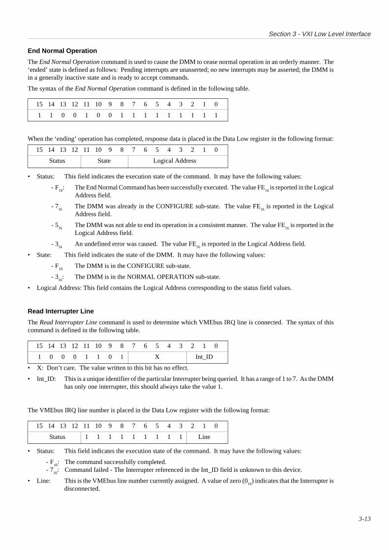
End Normal Operation
The End Normal Operation command is used to cause the DMM to cease normal operation in an orderly manner. The‘ended’ state is defined as follows: Pending interrupts are unasserted; no new interrupts may be asserted; the DMM isin a generally inactive state and is ready to accept commands.
The syntax of the End Normal Operation command is defined in the following table.
15 14 13 12 11 10 9 8 7 6 5 4 3 2 1 0
1 1 0 0 1 0 0 1 1 1 1 1 1 1 1 1
When the ‘ending’ operation has completed, response data is placed in the Data Low register in the following format:
15 14 13 12 11 10 9 8 7 6 5 4 3 2 1 0
Status State Logical Address
• Status: This field indicates the execution state of the command. It may have the following values:
- F16
: The End Normal Command has been successfully executed. The value FE16
is reported in the LogicalAddress field.
- 716
The DMM was already in the CONFIGURE sub-state. The value FE16
is reported in the LogicalAddress field.
- 516
The DMM was not able to end its operation in a consistent manner. The value FE16
is reported in theLogical Address field.
- 316
An undefined error was caused. The value FE16
is reported in the Logical Address field.
• State: This field indicates the state of the DMM. It may have the following values:
- F16
The DMM is in the CONFIGURE sub-state.
- 316
: The DMM is in the NORMAL OPERATION sub-state.
• Logical Address: This field contains the Logical Address corresponding to the status field values.
Read Interrupter Line
The Read Interrupter Line command is used to determine which VMEbus IRQ line is connected. The syntax of thiscommand is defined in the following table.
15 14 13 12 11 10 9 8 7 6 5 4 3 2 1 0
1 0 0 0 1 1 0 1 X Int_ID
• X: Don’t care. The value written to this bit has no effect.
• Int_ID: This is a unique identifier of the particular Interrupter being queried. It has a range of 1 to 7. As the DMMhas only one interrupter, this should always take the value 1.
The VMEbus IRQ line number is placed in the Data Low register with the following format:
15 14 13 12 11 10 9 8 7 6 5 4 3 2 1 0
Status 1 1 1 1 1 1 1 1 1 Line
• Status: This field indicates the execution state of the command. It may have the following values:
- F16
: The command successfully completed.- 7
16: Command failed - The Interrupter referenced in the Int_ID field is unknown to this device.
• Line: This is the VMEbus line number currently assigned. A value of zero (016
) indicates that the Interrupter isdisconnected.
Section 3 - VXI Low Level Interface
3-14
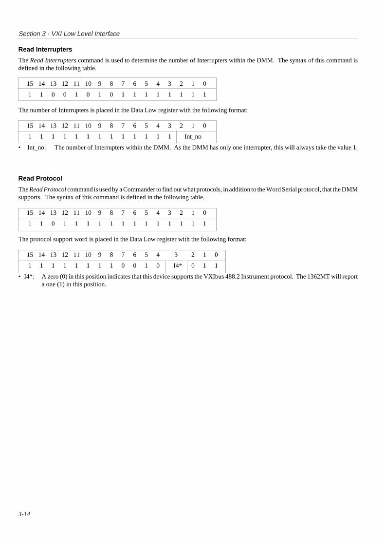
Read Interrupters
The Read Interrupters command is used to determine the number of Interrupters within the DMM. The syntax of this command isdefined in the following table.
15 14 13 12 11 10 9 8 7 6 5 4 3 2 1 0
1 1 0 0 1 0 1 0 1 1 1 1 1 1 1 1
The number of Interrupters is placed in the Data Low register with the following format:
15 14 13 12 11 10 9 8 7 6 5 4 3 2 1 0
1 1 1 1 1 1 1 1 1 1 1 1 1 Int_no
• Int_no: The number of Interrupters within the DMM. As the DMM has only one interrupter, this will always take the value 1.
Read Protocol
The Read Protocol command is used by a Commander to find out what protocols, in addition to the Word Serial protocol, that the DMMsupports. The syntax of this command is defined in the following table.
15 14 13 12 11 10 9 8 7 6 5 4 3 2 1 0
1 1 0 1 1 1 1 1 1 1 1 1 1 1 1 1
The protocol support word is placed in the Data Low register with the following format:
15 14 13 12 11 10 9 8 7 6 5 4 3 2 1 0
1 1 1 1 1 1 1 1 0 0 1 0 I4* 0 1 1
• I4*: A zero (0) in this position indicates that this device supports the VXIbus 488.2 Instrument protocol. The 1362MT will reporta one (1) in this position.

Section 3 - VXI Low Level Interface
3-15
Read Protocol Error
The Read Protocol Error command is used by a Commander to tell the DMM to report its most-recent error code. When the error codehas been reported by the DMM, the Err* bit is reset before Read Ready is asserted on the error code output. The syntax of this commandis defined in the following table.
15 14 13 12 11 10 9 8 7 6 5 4 3 2 1 0
1 1 0 0 1 1 0 1 1 1 1 1 1 1 1 1
The error codes are placed in the Data Low register with the following format:
• No error:
15 14 13 12 11 10 9 8 7 6 5 4 3 2 1 0
1 1 1 1 1 1 1 1 1 1 1 1 1 1 1 1
• Multiple Queries: The DMM was requested to overwrite previous unread response data.
15 14 13 12 11 10 9 8 7 6 5 4 3 2 1 0
1 1 1 1 1 1 1 1 1 1 1 1 1 1 0 1
• Unsupported Command: The DMM has received a command that it does not implement.
15 14 13 12 11 10 9 8 7 6 5 4 3 2 1 0
1 1 1 1 1 1 1 1 1 1 1 1 1 1 0 0
• DIR Violation: The DMM has received a command that violates the DIR handshake.
15 14 13 12 11 10 9 8 7 6 5 4 3 2 1 0
1 1 1 1 1 1 1 1 1 1 1 1 1 0 1 1
• DOR Violation: The DMM has received a command that violates the DOR handshake.
15 14 13 12 11 10 9 8 7 6 5 4 3 2 1 0
1 1 1 1 1 1 1 1 1 1 1 1 1 0 1 0
Read STB
The Read STB command is used by a Commander to read the status word from the DMM. The syntax of this command is defined inthe following table.
15 14 13 12 11 10 9 8 7 6 5 4 3 2 1 0
1 1 0 0 1 1 1 1 1 1 1 1 1 1 1 1
The error codes are placed in the Data Low register with the following format:
15 14 13 12 11 10 9 8 7 6 5 4 3 2 1 0
1 1 1 1 1 1 1 1 Status Byte
Trigger
The Trigger command is used by a Commander to cause the DMM to trigger.The syntax of this command is defined in the following table.
15 14 13 12 11 10 9 8 7 6 5 4 3 2 1 0
1 1 1 0 1 1 0 1 1 1 1 1 1 1 1 1

this page deliberately left blank

SECTION 41362S SCPI LANGUAGE
4-1
4-2
Section 4 - SCPI Language
SECTION 4 1362S SCPI LANGUAGE
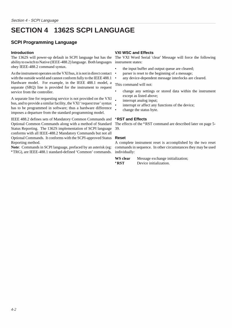
IntroductionThe 1362S will power-up default in SCPI language but has theability to switch to Native (IEEE-488.2) language. Both languagesobey IEEE-488.2 command syntax.
As the instrument operates on the VXI bus, it is not in direct contactwith the outside world and cannot conform fully to the IEEE 488.1Hardware model. For example, in the IEEE 488.1 model, aseparate (SRQ) line is provided for the instrument to requestservice from the controller.
A separate line for requesting service is not provided on the VXIbus, and to provide a similar facility, the VXI ‘request true’ syntaxhas to be programmed in software; thus a hardware differenceimposes a departure from the standard programming model.
IEEE 488.2 defines sets of Mandatory Common Commands andOptional Common Commands along with a method of StandardStatus Reporting. The 1362S implementation of SCPI languageconforms with all IEEE-488.2 Mandatory Commands but not allOptional Commands. It conforms with the SCPI-approved StatusReporting method.Note: Commands in SCPI language, prefaced by an asterisk (eg:∗TRG), are IEEE-488.1 standard-defined ‘Common’ commands.
VXI WSC and EffectsThe VXI Word Serial 'clear' Message will force the followinginstrument states:
• the input buffer and output queue are cleared;• parser is reset to the beginning of a message;• any device-dependent message interlocks are cleared.
This command will not:
• change any settings or stored data within the instrumentexcept as listed above;
• interrupt analog input;• interrupt or affect any functions of the device;• change the status byte.
∗RST and EffectsThe effects of the ∗RST command are described later on page 5-39.
ResetA complete instrument reset is accomplished by the two resetcommands in sequence. In other circumstances they may be usedindividually:
WS clear Message exchange initialization;∗RST Device initialization.
SCPI Programming Language

4-3
Section 4 - SCPI Language
Message Exchange
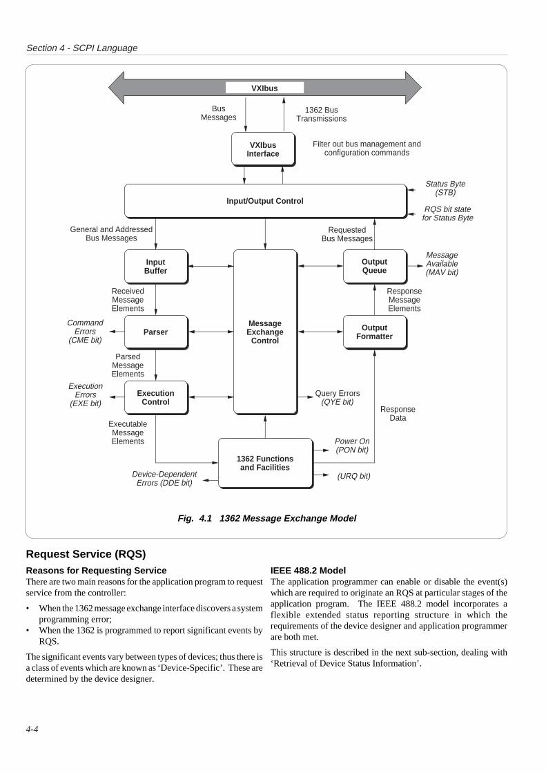
IEEE 488.2 ModelThe IEEE 488.2 Standard document illustrates its MessageExchange Control Interface model at the detail level required bythe device designer. Much of the information at this level ofinterpretation (such as the details of the internal signal paths etc.)is transparent to the application programmer. However, becauseeach of the types of errors flagged in the Event Status Register arerelated to a particular stage in the process, a simplified 1362interface model can provide helpful background. This is shown inFig. 4.1, together with brief descriptions of the actions of itsfunctional blocks.
1362S STATUS SubsystemInput/Output Control transfers messages from the 1362 outputqueue to the system bus; and conversely from the bus to either theinput buffer, or other predetermined destinations within the deviceinterface. It receives the Status Byte from the status reportingsystem, as well as the state of the Request Service bit which itimposes on bit 6 of the Status Byte response. Bit 6 reflects the‘Request Service state true’ condition of the interface.
Incoming Commands and QueriesThe Input Buffer is a first in - first out queue, which has amaximum capacity of 128 bytes (characters). Each incomingcharacter in the I/O Control generates an interrupt to the instrumentprocessor which places it in the Input Buffer for examination by theParser. The characters are removed from the buffer and translatedwith appropriate levels of syntax checking. If the rate ofprogramming is too fast for the Parser or Execution Control, thebuffer will progressively fill up. When the buffer is full, the VXICommander is informed by DIR being false. Refer to Section 3.
The Parser checks each incoming character and its messagecontext for correct Standard-defined generic syntax, and correctdevice-defined syntax. Offending syntax is reported as aCommand Error , by setting true bit 5 (CME) of the Standard-defined Event Status register (refer to the sub-section ‘Retrieval ofDevice Status Information’).
Execution Control receives successfully parsed messages, andassesses whether they can be executed, given the currently-programmed state of the 1362 functions and facilities. If a messageis not viable (eg the calibration trigger: CALL? when calibrationis not enabled); then an Execution Error is reported, by setting truebit 4 (EXE) of the Standard-defined Event Status register. Viablemessages are executed in order, altering the 1362 functions,facilities etc. Execution does not ‘overlap’ commands; instead,the 1362 Execution Control processes all commands‘Sequentially’ (ie. waits for actions resulting from the previouscommand to complete before executing the next).
1362 Functions and FacilitiesThe 1362 Functions and Facilities block contains all the device-specific functions and features of the 1362, accepting ExecutableMessage Elements from Execution Control and performing theassociated operations. It responds to any of the elements which arevalid Query Requests (both IEEE 488.2 Common QueryCommands and 1362 Device-specific Commands) by sending anyrequired Response Data to the Response Formatter (after carryingout the assigned internal operations).
Device-dependent errors are detected in this block. Bit 3 (DDE)of the Standard-defined Event Status register is set true when aninternal operating fault is detected, for instance during a self test.Each reportable error has a listed number, which is appended to anassociated queue as the error occurs.
Trigger ControlTwo types of message are used to trigger the 1362 A-D into takinga measurement:
A Word Serial 'trigger'∗TRG (IEEE 488.2-defined)
In the 1362 either message is passed through the Input Buffer,receiving the same treatment as a program message unit, beingparsed and executed as normal.
Outgoing ResponsesThe Response Formatter derives its information from ResponseData (being supplied by the Functions and Facilities block) andvalid Query Requests. From these it builds Response MessageElements, which are placed as a Response Message into the OutputQueue.
The Output Queue acts as a store for outgoing messages until theyare read over the system bus by the application program. For aslong as the output queue holds one or more bytes, it reports the factby setting true bit 4 (Message Available - MAV) of the Status Byteregister. Bit 4 is set false when the output queue is empty (refer tothe sub-section ‘Retrieval of Device Status Information’). The'DOR' bit set performs the same action. Refer to Section 3.
‘Query Error’This is an indication that the controller is following aninappropriate message exchange protocol, resulting in theInterrupted, Unterminated or Deadlocked condition:
Refer to 'Bit 2' on page 4-8.
The Standard document defines the 1362’s response, part of whichis to set true bit 2 (QYE) of the Standard-defined Event Statusregister.
4-4
Section 4 - SCPI Language
Request Service (RQS)Reasons for Requesting ServiceThere are two main reasons for the application program to requestservice from the controller:
• When the 1362 message exchange interface discovers a systemprogramming error;
• When the 1362 is programmed to report significant events byRQS.
The significant events vary between types of devices; thus there isa class of events which are known as ‘Device-Specific’. These aredetermined by the device designer.
IEEE 488.2 ModelThe application programmer can enable or disable the event(s)which are required to originate an RQS at particular stages of theapplication program. The IEEE 488.2 model incorporates aflexible extended status reporting structure in which therequirements of the device designer and application programmerare both met.
This structure is described in the next sub-section, dealing with‘Retrieval of Device Status Information’.
Fig. 4.1 1362 Message Exchange Model
VXIbus
BusMessages
1362 BusTransmissions
General and AddressedBus Messages
OutputFormatter
OutputQueue
MessageExchange
Control
InputBuffer
Parser
ExecutionControl
1362 Functionsand Facilities
Input/Output Control
ReceivedMessageElements
ParsedMessageElements
ExecutableMessageElements
ResponseMessageElements
ResponseData
RequestedBus Messages
CommandErrors
(CME bit)
ExecutionErrors
(EXE bit)
Device-DependentErrors (DDE bit)
Query Errors(QYE bit)
MessageAvailable(MAV bit)
Status Byte(STB)
RQS bit state for Status Byte
Power On(PON bit)
(URQ bit)
VXIbus Interface
Filter out bus management and configuration commands
4-5
Section 4 - SCPI Language
IntroductionRetrieval of Device Status Information
For any remotely-operated system, the provision of up-to-dateinformation about the performance of the system is of majorimportance. This is particularly so in the case of systems whichoperate under automatic control, as the controller requires thenecessary information feedback to enable it to progress theprogrammed task, and any break in the continuity of the processcan have serious results.
When developing an application program, the programmer needsto test and revise it, knowing its effects. Confidence that theprogram elements are couched in the correct grammar and syntax(and that the program commands and queries are thus beingaccepted and acted upon), helps to reduce the number of iterationsneeded to confirm and develop the viability of the whole program.So any assistance which can be given in closing the informationloop must benefit both program compilation and subsequent use.
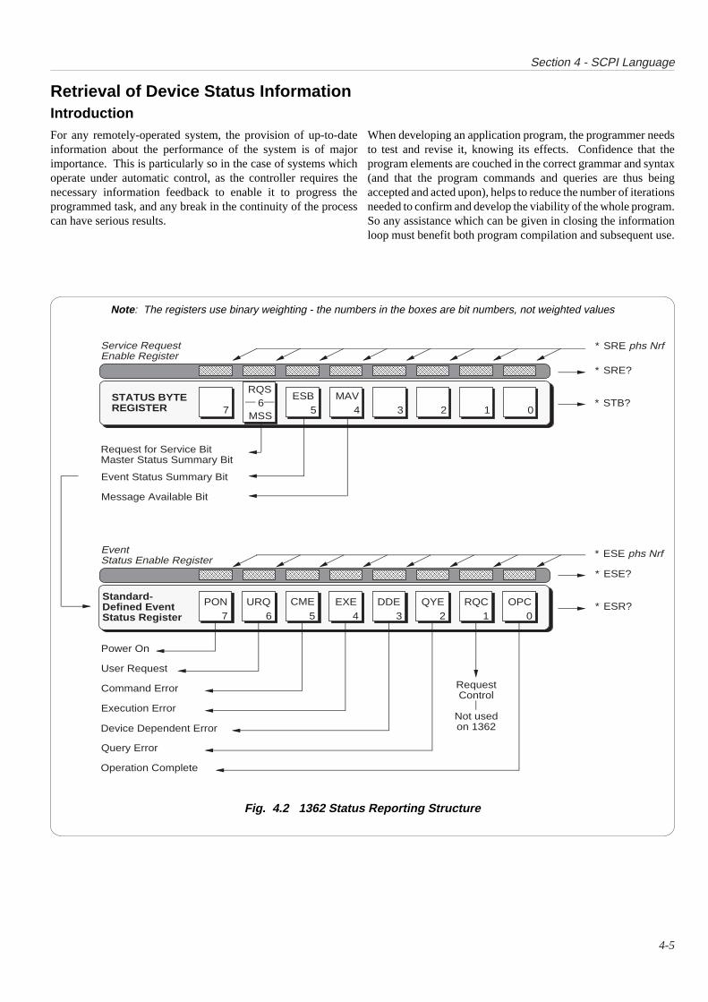
Note : The registers use binary weighting - the numbers in the boxes are bit numbers, not weighted values
Fig. 4.2 1362 Status Reporting Structure
0MSS
ESB MAVSTATUS BYTEREGISTER
Request for Service BitMaster Status Summary Bit
Event Status Summary Bit
Message Available Bit
AAAAAA
AAAAAA
AAAAAAAA
AAAAAAAA
AAAAAA
AAAAAA
AAAAAA
AAAAAA
Service RequestEnable Register
7 6 5 4 3 2 1 0PON URQ CME OPCEXE DDE QYE
Query Error
Power On
User Request
Command Error
Execution Error
Device Dependent Error
Operation Complete
Standard-Defined EventStatus Register
RQC
RequestControl
Not usedon 1362
AAAAAA
AAAAAA
AAAAAAAA
AAAAAAAA
AAAAAA
AAAAAA
AAAAAA
AAAAAA
EventStatus Enable Register
76
5 4 3 2 1
RQS
∗ SRE phs Nrf
∗ SRE?
∗ STB?
∗ ESE phs Nrf
∗ ESE?
∗ ESR?

4-6
Section 4 - SCPI Language
Types of Status Information AvailableTwo main categories of information are provided for thecontroller:
Status Summary InformationCertain standard events are flagged in the 8-bit latched ‘EventStatus Register’ (ESR), read-accessible to the controller. Theuser’s application program can also access its associated enablingregister, to program the events which will be eligible to activate the'ESB' summary bit in the Status Byte.
Status Byte RegisterContained within the ‘Status Byte Register’, the ‘Status Byte’(STB) consists of three flag bits which direct the controller’sattention to the type of event which has occurred. One is the ESBbit mentioned above, the other two (MAV and MSS) are describedin detail later.
Access via the Application ProgramThe application designer has access to two enable registers (one foreach main register - Fig. 4.2). The application program can enableor disable any individual bit in these registers.
Each bit in the event status register remains in false conditionunless its assigned event occurs, when its condition changes totrue. If an event is to be reported, the application program sets itscorresponding enable bit true, using the number Nrf (defined as adecimal numeric from 0 to 255 in any common format). Thenwhen the enabled event occurs and changes the enabled bit fromfalse to true, the ESB summary bit in the Status Byte is also set true.If the ESB bit is also enabled, then the 1362 will generate a requesttrue event on the VXI bus.
Thus the application programmer can decide which assignedevents will generate an event, by enabling their event bits and thenenabling the ESB bit in the Status Byte. The application programcan read the Status Byte, and be directed to the Event Register todiscover which event was responsible for originating the request.
All registers can be read by suitable commands, as an ASCIIdecimal numeric, which when expressed in binary, represents thebit pattern in the register. This form is also used to set the enablingregisters to the required bit-patterns. The detail for each register isexpanded in the following paragraphs, and in the commanddescriptions.
Standard-Defined Features

4-7
Section 4 - SCPI Language
1362 Status Reporting - Detail
IEEE 488.2 ModelThis incorporates the two aspects of the IEEE 488.1 model into anextended structure with more definite rules. These rules invoke theuse of standard ‘Common’ messages and provide for device-dependent messages. A feature of the structure is the use of ‘Event’registers, each with its own enabling register as shown in Fig. 4.2.
1362 Model StructureThe IEEE 488.2 Standard provides for an extensive hierarchicalstructure with the Status Byte at the apex, defining its bits 4, 5 and6 and their use as summaries of a Standard-defined event structurewhich must be included, if the device is to claim conformance withthe Standard. The 1362 employs these bits as defined in theStandard.
Bits 0, 1, 2 and 3 and 7 are made available to the device designer,but are not used in the 1362.
It must be recognized by the application programmer thatwhenever the controller reads the Status Byte, it can only receivesummaries of types of events, and further query messages arenecessary to dig deeper into the detailed information relating to theevents themselves. Thus a further byte is used to expand on thesummary at bit 5 of the Status Byte.
Status Byte RegisterIn this structure the Status Byte is held in the ‘Status ByteRegister’; the bits being allocated as follows:
Bits 0 (DIO1), 1 (DIO2), 2 (DIO3) and 3 (DIO4) are not used in the1362 status byte. They are always false.
Bit 4 (DIO5) IEEE 488.2-defined Message Available Bit(MAV)
The MAV bit helps to synchronize information exchange with thecontroller. It is true when the 1362 message exchange interface isready to accept a request from the controller to start outputtingbytes from the Output Queue; or false when the Output Queue isempty.
The common command ∗CLS can clear the Output Queue, and theMAV bit 4 of the Status Byte Register; providing it is sentimmediately following a ‘Program Message Terminator’.
Bit 5 (DIO6) IEEE 488.2-defined Standard Event SummaryBit (ESB)
Summarizes the state of the ‘Event Status byte’, held in the ‘EventStatus register’ (ESR), whose bits represent IEEE 488.2-definedconditions in the device. The ESB bit is true when the byte in theESR contains one or more enabled bits which are true; or falsewhen all the enabled bits in the byte are false. The byte, the EventStatus Register and its enabling register are defined by the IEEE488.1 Standard; they are described later.
Bit 6 (DIO7) is the Master Status Summary Message (MSS bit),and is set true if one of the bits 0 to 4 or bit 5 is true (bits 0 to 3 andbit 7 are always false in the 1362).
Bit 7 (DIO8) is not used in the 1362 status byte. It is always false.
Reading the Status Byte Register∗STB?Either the common query: ∗STB?, or the VXI word serial 'readSTB' command (Section 3), reads the binary number in the StatusByte register. The response is in the form of a decimal numberwhich is the sum of the binary weighted values in the enabled bitsof the register. In the 1362, the binary-weighted values of bits 1,2, 3 and 7 are always zero.

4-8
Section 4 - SCPI Language
Service Request Enable RegisterThe SRE register is a means for the application program to select,by enabling individual Status Byte summary bits, those types ofevents which are to cause the 1362 to originate an RQS. It containsa user-modifiable image of the Status Byte, whereby each true bitacts to enable its corresponding bit in the Status Byte.
Bit Selector: ∗SRE phs NrfThe program command: ∗SRE phs Nrf performs the selection,where Nrf is a decimal numeric, which when decoded into binaryproduces the required bit-pattern in the enabling byte.
For example:If an RQS is required only when a Standard-defined eventoccurs and when a message is available in the output queue,then Nrf should be set to 48. The binary decode is 00110000so bit 4 or bit 5, when true, will generate an RQS; but even whenbit 0 or bit 6 is true, no RQS will result. The 1362 always setsthe Status Byte bits 1, 2, 3 and 7 false, so they can neveroriginate an RQS whether enabled or not.
Reading the Service Request Enable RegisterThe common query: ∗SRE? reads the binary number in the SREregister. The response is in the form of a decimal number whichis the sum of the binary-weighted values in the register. Thebinary-weighted values of bits 1, 2, 3 and 7 are always zero.
VXIbus ImplementationAn RQS is implemented as a 'request true' event on the VXIbus.Refer to Section 3.
IEEE 488.2-defined Event Status RegisterThe ‘Event Status Register’ holds the Event Status Byte,consisting of event bits, each of which directs attention toparticular information. All bits are ‘sticky’; ie. once true, cannotreturn to false until the register is cleared. This occursautomatically when it is read by the query: ∗ESR?. The commoncommand ∗CLS clears the Event Status Register and associatederror queues, but not the Event Status Enable Register. The bits arenamed in mnemonic form as follows:
Bit 0 Operation Complete (OPC)This bit is true only if ∗OPC has been programmed and all selectedpending operations are complete. As the 1362 operates in serialmode, its usefulness is limited to registering the completion of longoperations, such as self-test.
Bit 1 Request Control (RQC)This bit would be true if the device were able to assume the role ofcontroller, and is requesting that control be transferred to it fromthe current controller. This capability is not available in the 1362,so bit 1 is always false.
Bit 2 Query Error (QYE)QYE true indicates that the controller is following an inappropriatemessage exchange protocol, resulting in the following situations:
• Interrupted Condition. When the 1362 has not finishedoutputting its Response Message to a Program Query, and isinterrupted by a new Program Message.
• Unterminated Condition. When the controller attempts toread a Response Message from the 1362 without having firstsent the complete Query Message (including the ProgramMessage Terminator) to the instrument.
• Deadlocked Condition. When the input and output buffers arefilled, with the parser and the execution control blocked.
Bit 3 Device Dependent Error (DDE)DDE is set true when an internal operating fault is detected, forinstance during a self test. Each reportable error has been given alisted number, which is appended to an associated queue as theerror occurs. The queue is read destructively as a First In Last Outstack, using the query command DDQ? to obtain a code number.The DDE bit is not a summary of the contents of the queue, but isset or confirmed true concurrent with each error as it occurs; andonce cleared by ∗ESR? will remain false until another error occurs.The query DDQ? can be used to read all the errors in the queue untilit is empty, when the code number zero will be returned.The common command ∗CLS clears the queue.
4-9
Section 4 - SCPI Language
Bit 4 Execution Error (EXE)An execution error is generated if the received command cannotbe executed, owing to the device state or the command parameterbeing out of bounds.
Bit 5 Command Error (CME)CME occurs when a received bus command does not satisfy theIEEE 488.2 generic syntax or the device command syntaxprogrammed into the instrument interface’s parser, and so is notrecognized as a valid command.
Bit 6 User Request (URQ)This bit is set true when, in block measurement mode, the numberof measurements programmed for the block measurement havebeen completed.
Bit 7 1362 Power Supply On (PON)This bit is not required in the VXI subsystem.
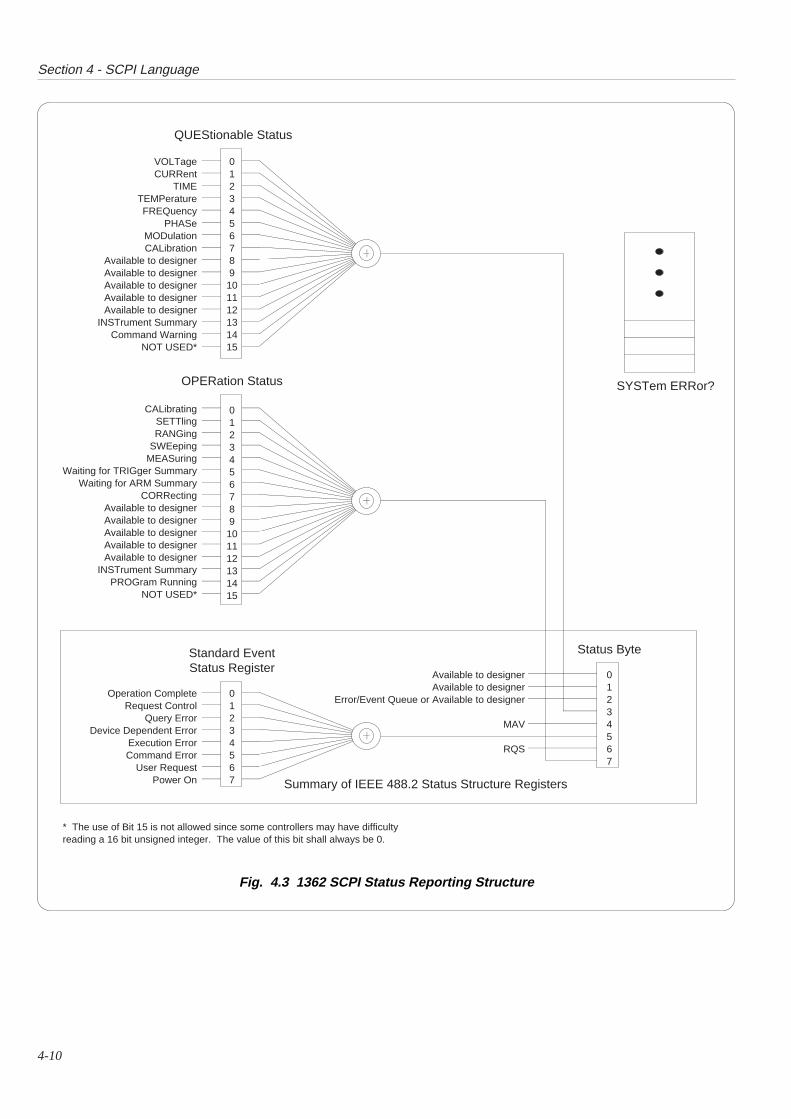
SCPI Additional Status ReportingIn addition to IEEE 488.2 status reporting the 1362S implementsthe Operation and Questionable Status register with associatedcondition, event and enable commands. The extra status deals withcurrent operation of the instrument and the quality of anymeasurements taken.
The structure of these two registers are detailed in Fig. 4.3 overleaf.The registers are detailed in the STATus subsystem on page 4-33of this handbook.
SCPI Syntax and StylesWhere possible the syntax and styles used in this section followthose defined by the SCPI consortium. The commands on thefollowing pages are broken into three columns; the KEYWORD,the PARAMETER FORM, and any NOTES.
The KEYWORD column provides the name of the command. Theactual command consists of one or more keywords since SCPIcommands are based on a hierarchical structure, also known as thetree system.
Square brackets ( [ ] ) are used to enclose a keyword that is optionalwhen programming the command: that is, the instrument 1362 willprocess the command to have the same effect whether the optionnode is omitted by the programmer or not.
Letter case in tables is used to differentiate between the acceptedshortform (upper case) and the long form (upper and lower case).
The PARAMETER FORM column indicates the number andorder of parameter in a command and their legal value. Parametertypes are distinguished by enclosing the type in angle brackets ( <> ). If parameter form is enclosed by square brackets ( [ ] ) theseare then optional. The vertical bar ( | ) can be read as "or" and isused to separate alternative parameter options.
QueriesAll commands unless otherwise noted have an addition queryform. ( for example INPut:COUPling? )
Native LanguageThe 1362S SCPI command capabilities are an extension to theexisting language now known as 'Native'. Native and SCPI areboth resident on the 1362S. Native was maintained to supportthose existing customers who may wish to retain their currentprograms. The 1362S defaults to SCPI on power on. Thecommands associated with switching to Native language can befound on page 4-36.
Standard Event Status Enable RegisterThe ESE register is a means for the application program to select,from the positions of the bits in the standard-defined Event StatusByte, those events which when true will set the ESB bit true in theStatus Byte. It contains a user-modifiable image of the standardEvent Status Byte, whereby each true bit acts to enable itscorresponding bit in the standard Event Status Byte.
Bit Selector: ∗ESE phs NrfThe program command: ∗ESE phs Nrf performs the selection,where Nrf is a decimal numeric, which when decoded into binary,produces the required bit-pattern in the enabling byte.
For example:If the ESB bit is required to be set true only when an executionor device-dependent error occurs, then Nrf should be set to 24.The binary decode is 00011000 so bit 3 or bit 4, when true, willset the ESB bit true; but when bits 0-2, or 5-7 are true, the ESBbit will remain false.
Reading the Standard Event Enable RegisterThe common query: ∗ESE? reads the binary number in the ESEregister. The response is in the form of a decimal number whichis the sum of the binary-weighted values in the register.
4-10
Section 4 - SCPI Language
Fig. 4.3 1362 SCPI Status Reporting Structure
VOLTageCURRent
TIMETEMPeratureFREQuency
PHASeMODulationCALibration
Available to designerAvailable to designerAvailable to designerAvailable to designerAvailable to designer
INSTrument SummaryCommand Warning
NOT USED*
0123456789101112131415
01234567
Available to designerAvailable to designer
Error/Event Queue or Available to designer
MAV
RQS
Standard EventStatus Register
OPERation Status
QUEStionable Status
Status Byte
Summary of IEEE 488.2 Status Structure Registers
SYSTem ERRor?
* The use of Bit 15 is not allowed since some controllers may have difficultyreading a 16 bit unsigned integer. The value of this bit shall always be 0.
CALibratingSETTlingRANGing
SWEepingMEASuring
Waiting for TRIGger SummaryWaiting for ARM Summary
CORRectingAvailable to designerAvailable to designerAvailable to designerAvailable to designerAvailable to designer
INSTrument SummaryPROGram Running
NOT USED*
Operation CompleteRequest Control
Query ErrorDevice Dependent Error
Execution ErrorCommand Error
User RequestPower On
0123456789101112131415
01234567
Section 4 - SCPI Language
4-11
1362S SCPI Language - Commands and SyntaxThe command subsystems are placed in alphabetical order.
The ABORt command returns the DMM to the IDLE state. Any measurements that are in progress will be completed before the DMMgoes into the IDLE state. See page 4-38, Fig. 4.4.
This command does not affect the settings of the trigger system and any subsequent INITiate will cause the DMM to return to thewait-for-trigger state as selected by the TRIGger:SOURce command. Refer to the TRIGger subsystem, page 4-38.
Syntax ABORt (Event, No query)
Related Commands INITiate , TRIGger
Query Format No Query.
Errors No errors associated with this command.
∗RST Condition There is no associated ∗RST condition. However, after the ∗RST the DMM is put in the IDLE state.
--------------------------------------
Native Equivalents There are no native equivalent commands.
ABORt

Section 4 - SCPI Language
4-12
CALibration Subsystem
This subsystem is used to calibrate the ranges and functions of the DMM. This will correct for any system errors due to drift or ageingeffects.
Before any calibration can take place, two security levels must be set. First, there is a switch on the DMM itself that must be set to CALENABLE. Having done this, the command CALibration:SECure ON must be sent.
Syntax CALibration:HIGH? [<numeric_value>] (manufacturer's extension):LOW? [<numeric_value>] (manufacturer's extension):SECure <Boolean> (manufacturer's extension):SLFRequency? (manufacturer's extension)
Related Commands There are no directly related commands, however commands to configure the DMM such as CONFigure ,SENSe etc. are used in conjunction with CALibration.See also Routine Calibration Procedure; section 8 of this handbook.
CALibration:HIGH? [<numeric_value>]CALibration:LOW? [<numeric_value>]
These commands are used to perform a calibration operation. In the case of :HIGH? , this will be at the full range value. In the caseof :LOW? this will be at zero for DC and Ohms, or at 1% of range for AC. The DMM will measure the input signal as a reference.From this measurement, correction factors are calculated and stored in the non-volatile memory. These correction factors will thenbe applied to all subsequent readings.
If the calibration operation is a success then the command returns a 0. If the command fails for any reason, then a 1 is returned andan error message is put in the error queue.
Note that to use this command the calibration switch must be set to CAL ENABLE and the command CALibration:STATe ONmust have been sent.
The optional parameter <numeric_value> gives the actual value of the reference being applied to the input terminals if this is not thenominal value.
Errors An error - 110,'Calibration switch disabled' will be generated if either the calibration switchis not set to enable and the CAL:SECure ON command has not been received.
Errors - 222,'Data out of range' will be generated if the <numeric_value> is out of range or themeasured value is out of range compared to the <numeric_value>
If the input is not connected, or the instrument is in DC coupled AC, or TRIG:SOURce IMM is not selected,then the error 120,'Calibration operation invalid' will be reported.
If the calibration fails for any other reason, then the message 122,'Calibration operationfailed' will be reported.
∗RST There is no associated ∗RST condition.
Notes Both CALibration:SECure ON and the hardware calibration switch found on the front panel have tobe enabled before calibration can take place. Four measurements are taken for every Calibration trigger. SeeSection 5-31 CVAL? command.
Section 4 - SCPI Language
4-13
CALibration:SECure <Boolean>
This command is used to enable the calibration mode. Before this command can be accepted, the calibration switch on the DMM mustbe set to CAL ENABLE. The accepted value for <Boolean> is OFF|0|1|ON .
Errors An error will be generated if CAL:SEC ON is received and the calibration switch is not set to CAL ENABLE.
Query CALibration:SECure?This queries the current setting of the secure mode. It returns either 0 for disabled, or 1 for enabled.
∗RST CALibration:SECure OFF .
CALibration:SLFRequency?
This query command is used to store the current setting of the ADC conversion line frequency into the non-volatile calibration stores.This value will then become the default value at power on and ∗RST.
The line frequency is set using the SENSe:LFRequency command (page 4-32).
Note that to use this command the calibration switch must be set to CAL ENABLE and the command CALibration:STATe ONmust have been sent.
Errors An error of 110,'Calibration switch disabled' shall be generated if either the calibration switchis not set to enable and the CAL:SECure ON command has not been received.
Query This command is a query only and will return 0 if the value is successfully stored, or 1 if the operation failed.
∗RST Last value set with an CAL:SLFR? command.
--------------------------------------
Native Equivalents CALibration:SECure ≡ CAL ON/OFF
CALibration:HIGH <...> ≡ CALH?
CALibration:LOW <...> ≡ CALL?
CALibration:SLFRequency? ≡ STLN?

Section 4 - SCPI Language
4-14
CONFigure
The CONFigure command subsystem is used to configure the DMM. It prepares the DMM to take a measurement but does not causea trigger.
Syntax CONFigure <function> <parameters>[,<source_list>]
Subsystem: CONFigure
Function: :CURRent[:DC] <parameters>[,<source_list>]:AC <parameters>[,<source_list>]
:FRESistance <parameters>[,<source_list>]:RESistance <parameters>[,<source_list>]:VOLTage
[:DC] <parameters>[,<source_list>]:AC <parameters>[,<source_list>]
Parameters: [<expected_value>[,<resolution>]]
Source List: [,[(@1)]|(@2)|(@1,2)|(@1:2)]
Related Commands FETCh?, INITiate, INPut, MEASure?, READ? CONFigure?
Note INPut:STATe <Boolean> should be ON before measurement takes place.See page 4-24 for further information on the INPut command.The <source list> will remain in the same state after a function change.
Description As shown by the syntax, the command:
CONFigure <function> <parameters>[,<source_list>]
is a compound command. The <function> selects which function the DMM measures. This may be voltage,current or resistance. Each function has associated parameters that are used to select the range and resolutionof subsequent measurements. There is then an optional <source_list> which selects which channel themeasurement is made on.
Note In the event of an error within the command, as much as possible of the command up to the error shall beimplemented. For example, if:
CONF:VOLT 1,1E-6,(@2)
is received on a single channel DMM, then the 1 volt DC 6.5 digit range would be selected, but the secondchannel selection would generate an error.

Section 4 - SCPI Language
4-15
CONFigure:CURRent[:DC] [<expected_value>[,<resolution>]]CONFigure:CURRent:AC [<expected_value>[,<resolution>]]
Either command selects the current measuring function. The default is for DC current, AC can be selected with the additional parameter.AC current with a DC component can be selected with the command:
INPut:COUPling AC|DC .See the INPut Subsystem page 4-24.
The <expected_value> is used to select the range of the function, however the DMM has only one range: 1 Amp.Thus all values will be accepted including the commands:
MAXimum, MINimum, AUTO, AUTO ON, AUTO OFF & DEFault
The optional <resolution> parameter is used to select the measurement resolution. There are three modes - 4.5, 5.5 and 6.5 digits.However, 6.5 digit resolution is not allowed in AC or DC coupled AC. The tables on the left below show the modes selected by numericvalues of <resolution> , those on the right show the modes selected by <resolution> commands:However, 6.5 digit resolution is not allowed in AC or DC coupled AC.
Function <resolution> selected
CURR[:DC] MAXimum 6.5 digit
MINimum 4.5 digit
AUTO 6.5 digit
AUTO ON 6.5 digit
AUTO OFF Resolution as last set
DEFault 6.5 digit
Function Range Required Digits6.5 5.5 4.5
CURR:DC 1A <1E-6> <1E-5> <1E-4>(1.000000A) (1.00000A) (1.0000A)
DC CurrentNumeric Values Used to Select Required Resolutions
DC CurrentResolutions Selected by Command
Function Range Required Digits5.5 4.5
CURR:AC 1A <1E-5> <1E-4>(1.00000A) (1.0000A)
Function <resolution> selected
CURR:AC MAXimum 5.5 digit
MINimum 4.5 digit
AUTO 5.5 digit
AUTO ON 5.5 digit
AUTO OFF Resolution as last set
DEFault 5.5 digit
AC CurrentResolutions Selected by Command
AC CurrentNumeric Values Used to Select Required Resolutions
Errors Current is an option and if the option is not fitted any CURRent command will generatethe error -241, 'Hardware missing' .
Query See CONFigure? command page 4-21.
∗RST CONF:CURR:DC 1, 1E-5 (Note that this function is inactive.)
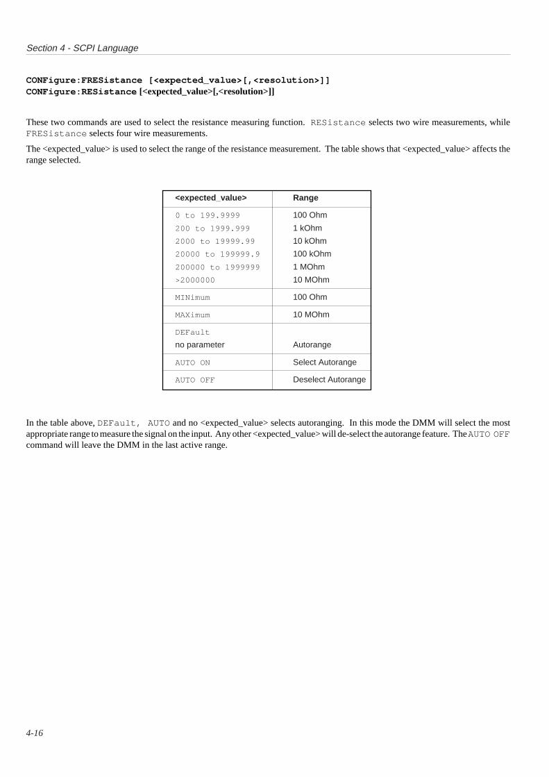
Section 4 - SCPI Language
4-16
CONFigure:FRESistance [<expected_value>[,<resolution>]]CONFigure:RESistance [<expected_value>[,<resolution>]]
These two commands are used to select the resistance measuring function. RESistance selects two wire measurements, whileFRESistance selects four wire measurements.
The <expected_value> is used to select the range of the resistance measurement. The table shows that <expected_value> affects therange selected.
In the table above, DEFault, AUTO and no <expected_value> selects autoranging. In this mode the DMM will select the mostappropriate range to measure the signal on the input. Any other <expected_value> will de-select the autorange feature. The AUTO OFFcommand will leave the DMM in the last active range.
<expected_value> Range
0 to 199.9999 100 Ohm
200 to 1999.999 1 kOhm
2000 to 19999.99 10 kOhm
20000 to 199999.9 100 kOhm
200000 to 1999999 1 MOhm
>2000000 10 MOhm
MINimum 100 Ohm
MAXimum 10 MOhm
DEFault
no parameter Autorange
AUTO ON Select Autorange
AUTO OFF Deselect Autorange
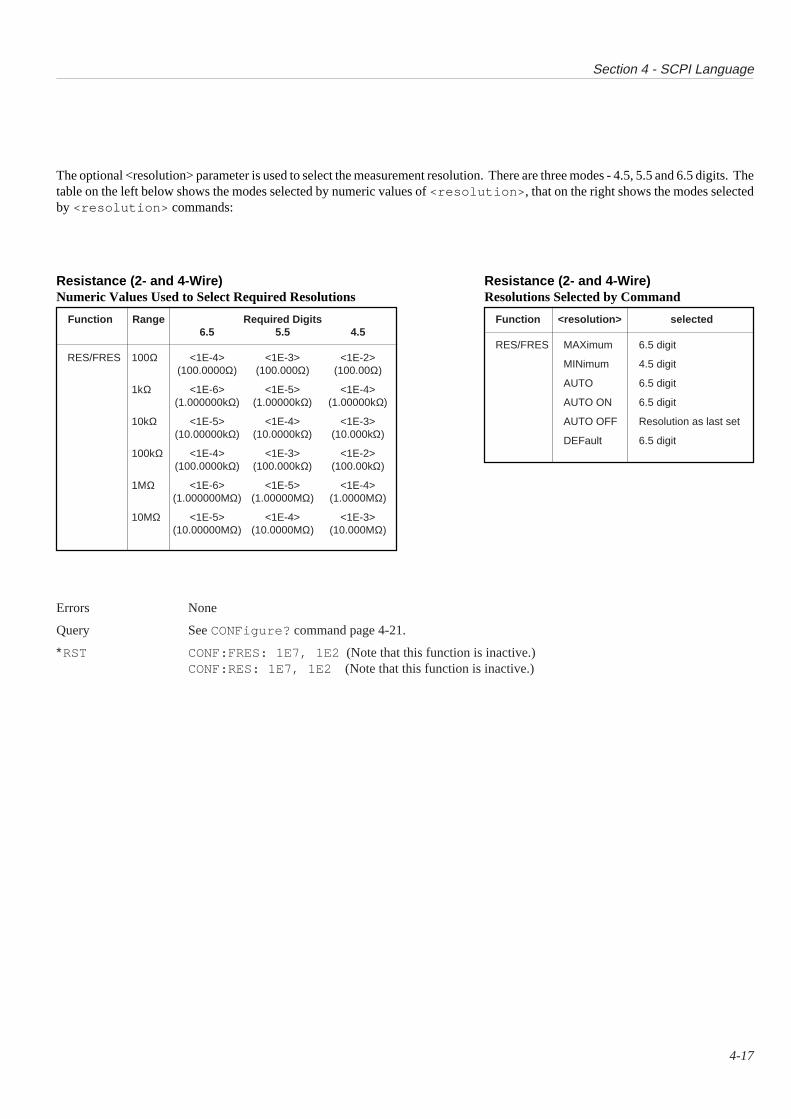
Section 4 - SCPI Language
4-17
Errors None
Query See CONFigure? command page 4-21.
∗RST CONF:FRES: 1E7, 1E2 (Note that this function is inactive.)CONF:RES: 1E7, 1E2 (Note that this function is inactive.)
The optional <resolution> parameter is used to select the measurement resolution. There are three modes - 4.5, 5.5 and 6.5 digits. Thetable on the left below shows the modes selected by numeric values of <resolution> , that on the right shows the modes selectedby <resolution> commands:
Function Range Required Digits6.5 5.5 4.5
RES/FRES 100Ω <1E-4> <1E-3> <1E-2>(100.0000Ω) (100.000Ω) (100.00Ω)
1kΩ <1E-6> <1E-5> <1E-4>(1.000000kΩ) (1.00000kΩ) (1.00000kΩ)
10kΩ <1E-5> <1E-4> <1E-3>(10.00000kΩ) (10.0000kΩ) (10.000kΩ)
100kΩ <1E-4> <1E-3> <1E-2>(100.0000kΩ) (100.000kΩ) (100.00kΩ)
1MΩ <1E-6> <1E-5> <1E-4>(1.000000MΩ) (1.00000MΩ) (1.0000MΩ)
10MΩ <1E-5> <1E-4> <1E-3>(10.00000MΩ) (10.0000MΩ) (10.000MΩ)
Resistance (2- and 4-Wire)Numeric Values Used to Select Required Resolutions
Function <resolution> selected
RES/FRES MAXimum 6.5 digit
MINimum 4.5 digit
AUTO 6.5 digit
AUTO ON 6.5 digit
AUTO OFF Resolution as last set
DEFault 6.5 digit
Resistance (2- and 4-Wire)Resolutions Selected by Command

Section 4 - SCPI Language
4-18
CONFigure:VOLTage[:DC] [<expected_value>[,<resolution>]]CONFigure:VOLTage:AC [<expected_value>[,<resolution>]]
Either command selects the voltage measuring function. The default is DC voltage, AC can be selected with the additional parameter.AC voltage with a DC component can be selected with the command INPut:COUPling AC|DC .See INPut Subsystem page 4-24.
The <expected_value> is used to select the range of the voltage measurement. The table shows how <expected_value> affects the rangeselected.
<expected_value> Range
0 to .1999999 100 mV
0.2 to 1.999999 1 V
2.0 to 19.99999 10 V
20.0 to 199.9999 100 V
>200 300 V
MINimum 100 mV
MAXimum 300 V
DEFault
no parameter Autorange
AUTO ON Select Autorange
AUTO OFF Deselect Autorange
In the above table, DEFault, AUTO and no <expected_value> selects autoranging. In this mode the DMM will select the mostappropriate range to measure the signal on the input. Any other <expected_value> will de-select the autorange feature. The AUTO OFFcommand will leave the DMM in the last active range.

Section 4 - SCPI Language
4-19
The optional <resolution> parameter is used to select the measurement resolution. There are three modes - 4.5, 5.5 and 6.5 digit.However, 6.5 digit resolution is not allowed in AC or DC coupled AC. The tables on the left below show the modes selected by numericvalues of <resolution> , those on the right show the modes selected by <resolution> commands:
Function Range Required Digits6.5 5.5 4.5
VOLT:[DC] 100mV <1E-4> <1E-3> <1E-2>(100.0000mV) (100.000mV) (100.00mV)
1V <1E-6> <1E-5> <1E-4>(1.000000V (1.00000V) (1.00000V)
10V <1E-5> <1E-4> <1E-3>(10.00000V) (10.0000V) (10.000V)
100V <1E-4> <1E-3> <1E-2>(100.0000V) (100.000V) (100.00V)
300V <1E-3> <1E-2> <1E-1>(300.000V) (300.00V) (300.0V)
DC VoltageNumeric Values Used to Select Required Resolutions
Function <resolution> selected
VOLT[:DC] MAXimum 6.5 digit
MINimum 4.5 digit
AUTO 6.5 digit
AUTO ON 6.5 digit
AUTO OFF Resolution as last set
DEFault 6.5 digit
DC VoltageResolutions Selected by Command
Function Range Required Digits5.5 4.5
VOLT:AC 100mV <1E-3> <1E-2>(100.000mV) (100.00mV)
1V <1E-5> <1E-4>(1.00000V) (1.00000V)
10V <1E-4> <1E-3>(10.0000V) (10.000V)
100V <1E-3> <1E-2>(100.000V) (100.00V)
300V <1E-2> <1E-1>(300.00V) (300.0V)
AC VoltageNumeric Values Used to Select Required Resolutions
Function <resolution> selected
VOLT:AC MAXimum 5.5 digit
MINimum 4.5 digit
AUTO 5.5 digit
AUTO ON 5.5 digit
AUTO OFF Resolution as last set
DEFault 5.5 digit
AC VoltageResolutions Selected by Command
Errors An error of - 241,'Data questionable' will be generated if greater than 6.5 digit resolution is selected.(or >5.5 for AC).
Query See CONFigure? command page 4-21.
∗RST CONF:VOLT:DC 300,1E-3 . This function is active.
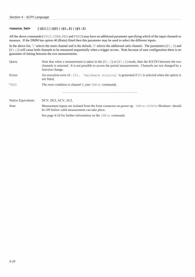
Section 4 - SCPI Language
4-20
<source_list> [(@1)]|(@2)|(@1,2)|(@1:2)
All the above commands (VOLT, CURR, RES and FRES) may have an additional parameter specifying which of the input channels tomeasure. If the DMM has option 40 (Ratio) fitted then this parameter may be used to select the different inputs.
In the above list, '1' selects the main channel and is the default, '2' selects the additional ratio channel. The parameters (@1,2) and(@1:2) will cause both channels to be measured sequentially when a trigger occurs. Note because of user configuration there is noguarantee of timing between the two measurements.
Query Note that when a measurement is taken in the (@1,2) or (@1:2) mode, then the RATIO between the twochannels is returned. It is not possible to access the partial measurements. Channels are not changed by afunction change.
Errors An execution error of - 241, 'Hardware missing' is generated if @2 is selected when the option isnot fitted.
∗RST The reset condition is channel 1, (see INPut command).
--------------------------------------
Native Equivalents DCV, DCI, ACV, ACI,
Note Measuement inputs are isolated from the front connector on power up. INPut:STATe <Boolean> shouldbe ON before valid measurement can take place.
See page 4-24 for further information on the INPut command.
Section 4 - SCPI Language
4-21
CONFigure?
This queries the current configuration of the DMM. Note that it returns the present setting of the DMM - not what was last set witha CONF command.
Syntax CONFigure? (Query Only)
Related Commands CONFigure, MEASure?, SENSe
CONFigure? This single command is used to query the current settings of the DMM, It returns a string in the form of :
"<function> <range>, <resolution>,<source_list>"
The possible combinations of the string are :
<function> <range> <resolution> <source_list>
CURR 1E-6 (@1)CURR:AC 1 1E-5 (@2)
1E-4 (@1,2)
1E21E3 <range>/1E-6 (@1)
RES 1E4 <range>/1E-5 (@2)FRES 1E5 <range>/1E-4 (@1,2)
1E61E7
1E-1VOLT 1E0 <range>/1E-6 (@1)VOLT:AC 1E1 <range>/1E-5 (@2)
1E2 <range>/1E-4 (@1,2)3E2
If AUTO, DEF, MIN or MAX was selected for <range> or <resolution> then the CONF? string will contain thecurrent setting that the DMM has selected.
Note that in the above the <resolution> depends on the range currently selected. Thus if the current activeselection is 10 volt , 5.5 digits, then the returned string would be :
VOLT:DC 1E1,1E-4,(@1)
In the case of the 300V range, then the resolution is returned as 1E-1 , 1E-2 or 1E-3 .
∗RST Query only, no associated ∗RST condition.
--------------------------------------
Native Equivalents *LRN

Section 4 - SCPI Language
4-22
FETCh?
This query command retrieves the last set of measurements taken and places them in the output queue. The returned data will be eithera single reading if 'block' mode is not selected, or the several readings if 'block' mode is selected.
Syntax FETCh? (Query only)
Related Commands CONFigure, INITiate, READ?
Qualifiers Note that the SCPI definition allows <function> and <parameter> qualifiers, but as the DMM only stores thereadings for the current setting, these commands are not implemented.
Query The returned data is formatted in the following character positions:
4.5 digit 1 2 3 4 5 6 7 8 9 10 11 12s n x x x n n E s n n t
5.5 digit 1 2 3 4 5 6 7 8 9 10 11 12 13s n x x x n n n E s n n t
6.5 digit 1 2 3 4 5 6 7 8 9 10 11 12 13 14s n x x x n n n n E s n n t
Wheres = the sign + or -n = ASCII digit 0 to 9x = either an n or a decimal pointE = ASCII character identifying the exponentt = a terminator or separator- either ; or , or <lf> (linefeed character)
The measurement overload condition is reported as 200.000E+33t
Multiple readings are returned with each value separated by a comma and the last reading terminated withthe linefeed character.
Errors If no measurement has been taken or the instrument has been reconfigured, then no result is returned and theerror - 230,'Data corrupt or stale' is stored in the error queue. This will be as a result of ∗RST,a CONF, SENSe etc command or after an INIT command has been sent.
∗RST Condition As this is a query command then there is no associated ∗RST condition. However note that ∗RST puts theDMM into the idle state and thus a FETCh? command would cause an error if no INIT had been received.
--------------------------------------
Native Equivalents RDG? BRCL?
Section 4 - SCPI Language
4-23
INITiate
This command removes the DMM from the idle state and into the wait for trigger state. When the trigger occurs the subsequent readingsare stored within the DMM. These can then be accessed by the FETCh? command. Any readings already in memory will beoverwritten.
Syntax INITiate[:IMMediate] (Event, No query)
Related Commands ABORt, CONFigure, FETCh?, READ?, TRIGger
INITiate[:IMMediate]
This puts the DMM into the wait for trigger state. The DMM will then wait for the appropriate trigger to occur before taking ameasurement. If the trigger state is set to TRIG:SOUR IMM then the DMM will take a reading immediately, without waiting forany other event.
Any other trigger state set by the TRIG:SOUR command will cause the DMM to wait until that event occurred before taking a reading.
The ABORt command can be used to remove the DMM from the wait for trigger state.
Once the pending trigger conditions have been met, and all the readings have been taken, then the DMM will return to the idle stateand another INIT command is required before further triggers are executed. The FETCh? command can be used to access thesereadings.
The READ? command executes an INITiate command implicitly and the MEASure? command executes a READ? commandimplicitly. Thus both commands will put the DMM into the wait for trigger state. Note that if TRIGger:SOURce IMMediateis in operation then these two commands will implicitly cause a trigger. Once the trigger has occured, then the measurement will beplaced in the output queue. Note that for external triggers, it will not be possible to communicate with the DMM until the trigger hasoccured. See Appendix A to this section for further details.
Query Format INIT is an event and cannot be queried.
Errors An error of - 213,'Init ignored' will be generated if the DMM is not in the idle state when thiscommand is received.
∗RST Condition There is no associated ∗RST condition, but note that the ∗RST places the DMM in the idle state.
--------------------------------------
Native Equivalents No direct equivalent, but is related to X?, *TRG

Section 4 - SCPI Language
4-24
INPut
Controls the connection of the input terminals to the signal to be measured. The command is also used to configure the remote guardand the state of the input filter.
Syntax:Subsytem INPut
Alternatives/Parameters :COUPling AC|DC:FILTer
[:LPASs][:STATe] <Boolean>
:GUARd LOW|FLOat[:STATe] <Boolean>:ZERO? (Manufacturer's extension)
Related commands CONFigure, MEASure?, SENSe
INPut:COUPling AC|DC
This command is used to cause the DMM to measure the DC component of an AC voltage signal. It is valid only when in AC voltagemeasurement, thus a CONF or SENSe command must have already selected the AC function.
If the command is received with the AC parameter, then the DMM will only measure the AC component. However sending the DCparameter will enable the DMM to measure the DC and the AC components of the signal.
Errors If the DMM is not in AC, then the error - 221,'Settings conflict' is generated.
Query INPut:COUPling?This will return either the string "AC" or "DC" . If the DMM is in the Ohms function, then this query willreturn "DC" .
∗RST INPut:COUPling AC - but inactive (See CONF:VOLT AC)
INPut:FILTer[:LPASs][:STATe] <Boolean>
This sub-system configures the state of the input filter of the DMM. As the DMM has effectively only a low pass filter, the other SCPIdefined parameters are not implemented.
Note that both :LPASs and :STATe are optional. If the value of <Boolean> is 0 or OFF, then the filter is deselected. If <Boolean>is 1 or ON then the filter is selected.
Errors No associated errors.
Query INPut:FILTer[:LPASs][:STATe]?This will return the string '0' if the filter is inactive or '1' if the filter is active.
∗RST INPut:FILTer:LPASs:STATe 0 (Low-pass Input Filter in OFF state)
Section 4 - SCPI Language
4-25
INPut:GUARd LOW|FLOat
This command sets the connection of the internal guard shield :
Errors No associated errors
Query INPut:GUARd?This queries the setting of the guard shield. Will return either "LOW" for internally connected, or "FLO" forconnected to guard terminal.
∗RST INPut:GUARd LOW
INPut[:STATe] <Boolean>
This command controls whether the input terminals are connected to the measurement signal. If <Boolean> is 0 or OFF then the DMMis isolated from the external signal source. If <Boolean> is 1 or ON, then the DMM input is connected to the external signal source.
Errors No directly associated errors; however, it is not possible to take measurements if the input is not connectedto the signal. Thus a command such as MEAS? and INIT:IMM can generate errors as a result of the settingof INPut:[STATe]
Query INPut[:STATe]?Returns either '0' if the input is disconnected or '1' if the input is connected.
∗RST INPut:[STATe] 0Note that this is different to that mandated by SCPI, but it is our policy to disconnect all instruments from thesignal lines. This isolation will improve safety and prevent internal damage due to inadvertently large inputsat power-on.
INPut:ZERO?
This command will cause the DMM to measure the current input value and subtract this from all subsequent readings for the setting(i.e. function and range etc.)
Errors An execution error is generated if the measured value is outside the range of the input zero correction range.The error 100,'Input not connected' is reported if this command is received and the input isdisconnected
Query INPut:ZERO?This command returns 1 for a fail, 0 for a successful input zero.
∗RST All input zero corrections are unaffected by ∗RST.
--------------------------------------
Native Equivalents INPut:COUPling AC|DC ≡ ACV ACCP DCCPINPut:FILter ≡ FILT0/FILT1 in DCV etc.INPut:[STATe] ≡ INPUT OFF, CH_A etc.INPut:ZERO ≡ ZERO?
Option Guard Connection
LOW Internally connected to signal common
FLOat connected to front panel guard terminal
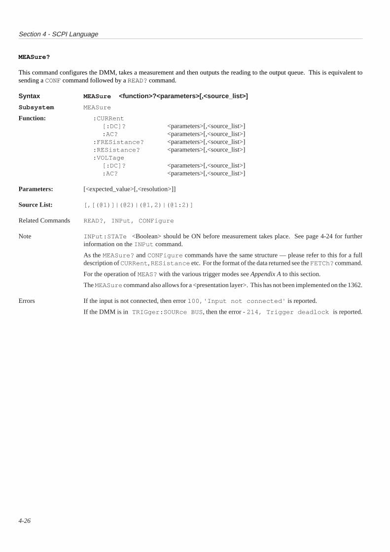
Section 4 - SCPI Language
4-26
MEASure?
This command configures the DMM, takes a measurement and then outputs the reading to the output queue. This is equivalent tosending a CONF command followed by a READ? command.
Syntax MEASure <function>?<parameters>[,<source_list>]
Subsystem MEASure
Function: :CURRent[:DC]? <parameters>[,<source_list>]:AC? <parameters>[,<source_list>]
:FRESistance? <parameters>[,<source_list>]:RESistance? <parameters>[,<source_list>]:VOLTage
[:DC]? <parameters>[,<source_list>]:AC? <parameters>[,<source_list>]
Parameters: [<expected_value>[,<resolution>]]
Source List: [,[(@1)]|(@2)|(@1,2)|(@1:2)]
Related Commands READ?, INPut, CONFigure
Note INPut:STATe <Boolean> should be ON before measurement takes place. See page 4-24 for furtherinformation on the INPut command.
As the MEASure? and CONFigure commands have the same structure — please refer to this for a fulldescription of CURRent, RESistance etc. For the format of the data returned see the FETCh? command.
For the operation of MEAS? with the various trigger modes see Appendix A to this section.
The MEASure command also allows for a <presentation layer>. This has not been implemented on the 1362.
Errors If the input is not connected, then error 100,'Input not connected' is reported.
If the DMM is in TRIGger:SOURce BUS , then the error - 214, Trigger deadlock is reported.
Section 4 - SCPI Language
4-27
OUTPut
This command is used to select the response mode of the DMM to a TTL trigger.
Syntax OUTPut:TTLTrg<n>:PROTocol SYNChronous|ASYNchronousWhere n = 0 through 7, referring to the eight backplane lines.
Related Commands TRIGger:SOURce:TTLTrg
OUTPut:TTLTrg<n>:PROTocol SYNChronous|ASYNchronous
This command is used to select the trigger protocol for the backplane TTL lines. The SYNChronous mode configures the eight TTLlines as individual trigger inputs. That is, a measurement can be triggered from any one of the lines if the line is selected andINITiated .
In the ASYNchronous mode, the eight lines are treated as four input/output pairs - 0/1, 2/3, 4/5, 6/7.
In this configuration the trigger is received on the lower number (i.e. TTLT0/2/4/6 ) and the measurement complete signal is outputon the higher number (i.e. TTLT1/3/5/7 ).
The ASYN command will select the pair of the currently active TTLT line.E.g. if TTLT5 is selected ASYN would select pair 4/5.
Refer to VXI Specifications revision 1.3 for further information on triggering protocols.
Query Format OUTPut:TTLTrg<n>:PROTocol?This query will return 'SYNC' or 'ASYN' depending on which is currently selected.
Errors No associated errors with this command.
∗RST Condition SYNChronous mode all TTLTrg lines deselected.
--------------------------------------
Native Equivalents None.
Section 4 - SCPI Language
4-28
READ?
This command places the DMM in a 'wait for trigger' state and then returns the measurement after the trigger. In effect this executesan INITiate and FETCh? command
Syntax READ? (Query only)
Related Commands CONFigure, FETCh? INITiate
Query See the FETCh? command for a description of the data format returned.
Errors An execution error - 100,'Input not connected' will be generated if the DMM input has not beenselected with the INPut command.
If the DMM is in TRIGger:SOURce BUS , then the error - 214, 'Trigger deadlock' is reported.
For the operation of READ? with the various trigger modes see Appendix A.
∗RST Condition Query command, no associated ∗RST state.
--------------------------------------
Native Equivalents X?
Section 4 - SCPI Language
4-29
[SENSe:]
This command is used to configure the DMM to a more detailed level that the CONFigure command.Note that :SENSe is a root level command and can be omitted. Thus only the VOLTage, FILTer etc. part of the command needbe sent. This command also selects the line frequency that the measurements are taken over.
Syntax [:SENSe]
Function :CURRent
[:DC]:RANGe <numeric_value>
:AUTO <Boolean>:RESolution <numeric_value>
:AC:RANGe <numeric_value>
:AUTO <Boolean>:RESolution <numeric_value>
:FRESistance:RANGe <numeric_value>
:AUTO <Boolean>:RESolution <numeric_value>
:RESistance:RANGe <numeric_value>
:AUTO <Boolean>:RESolution <numeric_value>
:VOLTage
[:DC]:RANGe <numeric_value>
:AUTO <Boolean>:RESolution <numeric_value>
:AC:RANGe <numeric_value>
:AUTO <Boolean>:RESolution <numeric_value>
:FILTer[:LPASs]
[:STATe] <Boolean>
:LFRequency <numeric_value> (manufacturer's extension)
Related Commands CONFigure, MEASure? INPut
As the six <function> defining sub-systems (see the list below) all have similar sub-levels, they will all be described together:
[:SENSe]:CURRent[:DC]:CURRent:AC:FRESistance:RESistance:VOLTage[:DC]:VOLTage:AC
Continued overleaf
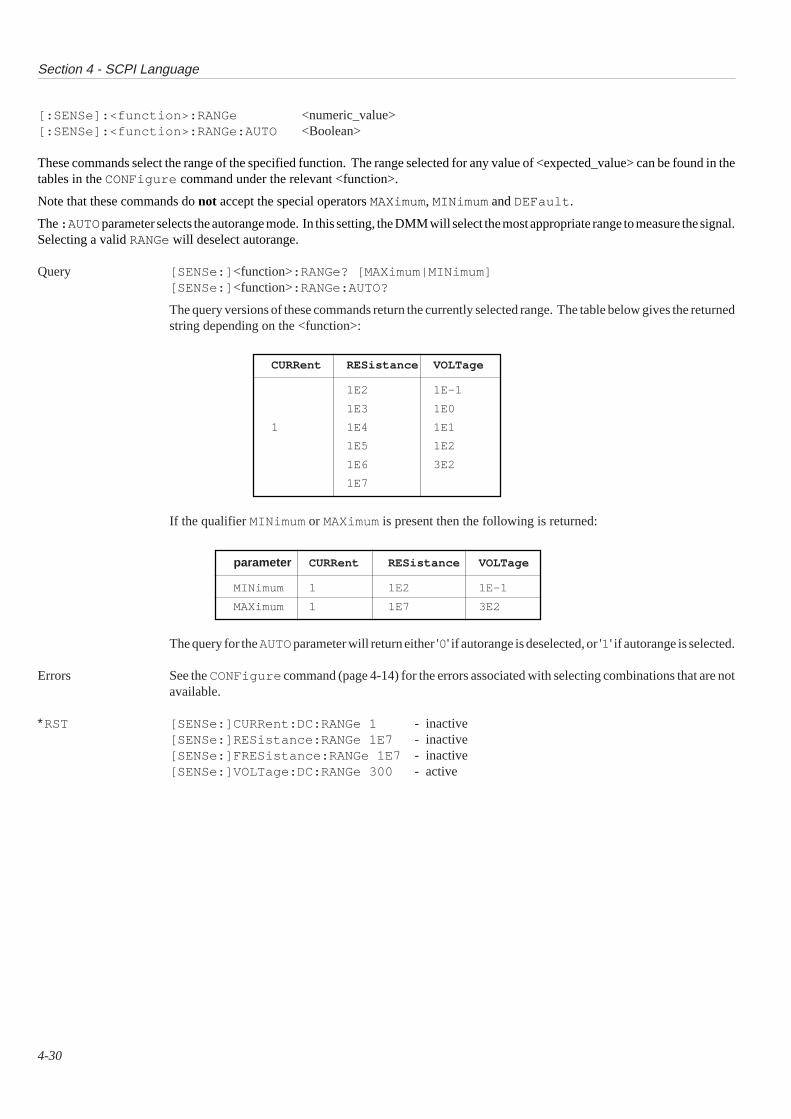
Section 4 - SCPI Language
4-30
[:SENSe]:<function>:RANGe <numeric_value>[:SENSe]:<function>:RANGe:AUTO <Boolean>
These commands select the range of the specified function. The range selected for any value of <expected_value> can be found in thetables in the CONFigure command under the relevant <function>.
Note that these commands do not accept the special operators MAXimum, MINimum and DEFault .
The :AUTO parameter selects the autorange mode. In this setting, the DMM will select the most appropriate range to measure the signal.Selecting a valid RANGe will deselect autorange.
Query [SENSe:] <function>:RANGe? [MAXimum|MINimum][SENSe:] <function>:RANGe:AUTO?
The query versions of these commands return the currently selected range. The table below gives the returnedstring depending on the <function>:
If the qualifier MINimum or MAXimum is present then the following is returned:
The query for the AUTO parameter will return either '0' if autorange is deselected, or '1' if autorange is selected.
Errors See the CONFigure command (page 4-14) for the errors associated with selecting combinations that are notavailable.
∗RST [SENSe:]CURRent:DC:RANGe 1 - inactive[SENSe:]RESistance:RANGe 1E7 - inactive[SENSe:]FRESistance:RANGe 1E7 - inactive[SENSe:]VOLTage:DC:RANGe 300 - active
CURRent RESistance VOLTage
1E2 1E-1
1E3 1E0
1 1E4 1E1
1E5 1E2
1E6 3E2
1E7
parameter CURRent RESistance VOLTage
MINimum 1 1E2 1E-1
MAXimum 1 1E7 3E2
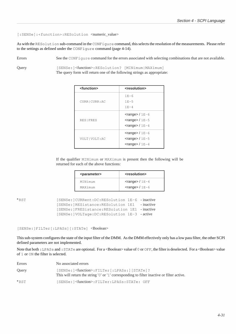
Section 4 - SCPI Language
4-31
[:SENSe]:<function>:RESolution <numeric_value>
As with the RESolution sub-command in the CONFigure command, this selects the resolution of the measurements. Please referto the settings as defined under the CONFigure command (page 4-14).
Errors See the CONFigure command for the errors associated with selecting combinations that are not available.
Query [SENSe:] <function>:RESolution? [MINimum|MAXimum]The query form will return one of the following strings as appropriate:
If the qualifier MINimum or MAXimum is present then the following will bereturned for each of the above functions:
∗RST [SENSe:]CURRent:DC:RESolution 1E-6 - inactive[SENSe:]RESistance:RESolution 1E1 - inactive[SENSe:]FRESistance:RESolution 1E1 - inactive[SENSe:]VOLTage:DC:RESolution 1E-3 - active
[SENSe:]FILTer[:LPASs][:STATe] <Boolean>
This sub-system configures the state of the input filter of the DMM. As the DMM effectively only has a low pass filter, the other SCPIdefined parameters are not implemented.
Note that both :LPASs and :STATe are optional. For a <Boolean> value of 0 or OFF, the filter is deselected. For a <Boolean> valueof 1 or ON the filter is selected.
Errors No associated errors
Query [SENSe:] <function>:FILTer[:LPASs:][STATe]?This will return the string '0' or '1' corresponding to filter inactive or filter active.
∗RST [SENSe:] <function>:FILTer:LPASs:STATe: OFF
<function> <resolution>
1E-6
CURR|CURR:AC 1E-5
1E-4
<range> / 1E-6
RES|FRES <range> / 1E-5
<range> / 1E-4
<range> / 1E-6
VOLT|VOLT:AC <range> / 1E-5
<range> / 1E-4
<parameter> <resolution>
MINimum <range> / 1E-4
MAXimum <range> / 1E-6

Section 4 - SCPI Language
4-32
<numeric_value> Line Frequency
(nv) selected
0 < nv ≤ 55 50 Hz
55 < nv ≤ 100 60 Hz
100 < nv 400 Hz
MINimum 50 Hz
MAXimum 400 Hz
DEFault 60 Hz
[:SENSe]LFRequency <numeric_value>
This command is a manufacturer-defined extension to the SCPI-confirmed [:SENSe] subsystem. It is used to set the line frequencyat which the ADC converts. The table below shows the accepted numeric values (nv) and the resulting line frequency selection. Anyother <numeric_value> will generate an error. The units are Hertz.
N.B. Partial Calibration of the 1362When carrying out a partial calibration, ensure that the programmed frequency is the same as that for the most-recent full calibration.Otherwise, small offsets may be introduced which can only be removed by a full calibration.
Errors If the parameter is less than zero an execution error will be generated.
Query [SENSe:]LFRequency?The query form of the command returns the current setting of the line frequency. and the current setting inthe calibration stores, These will be either 50 , 60 or 400 and the two values will be comma separated e.g.
50,60 <lf>
This would indicate that the tempory line frequency is 50 Hz, but the default power on setting is 60 Hz.
Note that the parameters MAX, MIN etc are not applicable in this command.
∗RST The line frequency remains unchanged as it is stored in the non-volatile store.
--------------------------------------
Native Equivalents DCV, DCI, ACV, ACI, OHMS, FILT, LINE
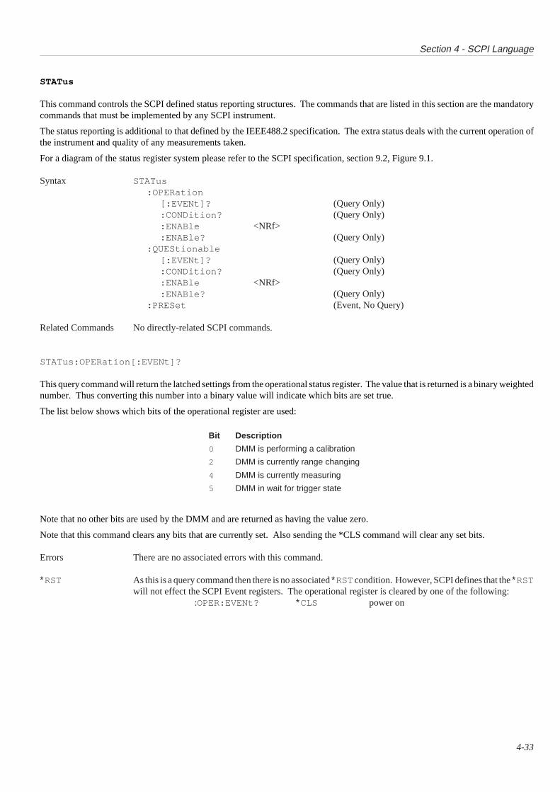
Section 4 - SCPI Language
4-33
STATus
This command controls the SCPI defined status reporting structures. The commands that are listed in this section are the mandatorycommands that must be implemented by any SCPI instrument.
The status reporting is additional to that defined by the IEEE488.2 specification. The extra status deals with the current operation ofthe instrument and quality of any measurements taken.
For a diagram of the status register system please refer to the SCPI specification, section 9.2, Figure 9.1.
Syntax STATus:OPERation
[:EVENt]? (Query Only):CONDition? (Query Only):ENABle <NRf>:ENABle? (Query Only)
:QUEStionable[:EVENt]? (Query Only):CONDition? (Query Only):ENABle <NRf>:ENABle? (Query Only)
:PRESet (Event, No Query)
Related Commands No directly-related SCPI commands.
STATus:OPERation[:EVENt]?
This query command will return the latched settings from the operational status register. The value that is returned is a binary weightednumber. Thus converting this number into a binary value will indicate which bits are set true.
The list below shows which bits of the operational register are used:
Note that no other bits are used by the DMM and are returned as having the value zero.
Note that this command clears any bits that are currently set. Also sending the *CLS command will clear any set bits.
Errors There are no associated errors with this command.
∗RST As this is a query command then there is no associated ∗RST condition. However, SCPI defines that the ∗RSTwill not effect the SCPI Event registers. The operational register is cleared by one of the following:
:OPER:EVENt? ∗CLS power on
Bit Description
0 DMM is performing a calibration
2 DMM is currently range changing
4 DMM is currently measuring
5 DMM in wait for trigger state
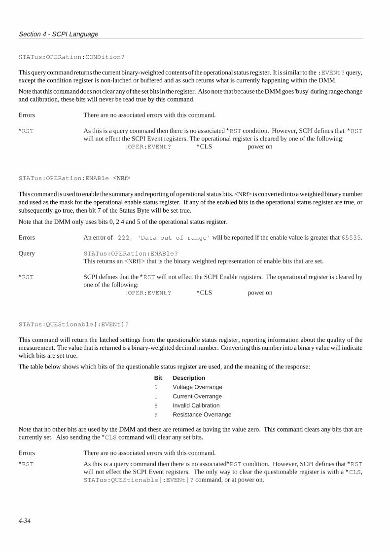
Section 4 - SCPI Language
4-34
STATus:OPERation:CONDition?
This query command returns the current binary-weighted contents of the operational status register. It is similar to the :EVENt? query,except the condition register is non-latched or buffered and as such returns what is currently happening within the DMM.
Note that this command does not clear any of the set bits in the register. Also note that because the DMM goes 'busy' during range changeand calibration, these bits will never be read true by this command.
Errors There are no associated errors with this command.
∗RST As this is a query command then there is no associated ∗RST condition. However, SCPI defines that ∗RSTwill not effect the SCPI Event registers. The operational register is cleared by one of the following:
:OPER:EVENt? ∗CLS power on
STATus:OPERation:ENABle <NRf>
This command is used to enable the summary and reporting of operational status bits. <NRf> is converted into a weighted binary numberand used as the mask for the operational enable status register. If any of the enabled bits in the operational status register are true, orsubsequently go true, then bit 7 of the Status Byte will be set true.
Note that the DMM only uses bits 0, 2 4 and 5 of the operational status register.
Errors An error of - 222, 'Data out of range' will be reported if the enable value is greater that 65535 .
Query STATus:OPERation:ENABle?This returns an <NRf1> that is the binary weighted representation of enable bits that are set.
∗RST SCPI defines that the ∗RST will not effect the SCPI Enable registers. The operational register is cleared byone of the following:
:OPER:EVENt? ∗CLS power on
STATus:QUEStionable[:EVENt]?
This command will return the latched settings from the questionable status register, reporting information about the quality of themeasurement. The value that is returned is a binary-weighted decimal number. Converting this number into a binary value will indicatewhich bits are set true.
The table below shows which bits of the questionable status register are used, and the meaning of the response:
Bit Description
0 Voltage Overrange
1 Current Overrange
8 Invalid Calibration
9 Resistance Overrange
Note that no other bits are used by the DMM and these are returned as having the value zero. This command clears any bits that arecurrently set. Also sending the ∗CLS command will clear any set bits.
Errors There are no associated errors with this command.
∗RST As this is a query command then there is no associated∗RST condition. However, SCPI defines that ∗RSTwill not effect the SCPI Event registers. The only way to clear the questionable register is with a ∗CLS,STATus:QUEStionable[:EVENt]? command, or at power on.
Section 4 - SCPI Language
4-35
STATus:QUEStionable:CONDition?
This query command returns the current binary weighted contents of the questionable status register. It is similar to the :EVENt? query,except the condition register is non-latched or buffered and as such returns what is currently happening within the DMM.
Note that this command does not clear any of the set bits in the register.
Errors There are no associated errors
∗RST As this is a query command, there is no associated ∗RST condition. However, SCPI defines that the *RSTwill not effect the SCPI Event registers. The only way to clear the questionable register is with a ∗CLScommand or at power on.
STATus:QUEStionable:ENABle <NRf>
This command is used to enable the summary and reporting of questionable status bits summarized by bit 3 of the IEEE 488.2 StatusByte. The value of <NRf> is converted into a weighted binary number and used as the mask for the operational enable status register.If any of the enabled bits in the operational status register are true, or subsequently go true, then bit 3 of the Status Byte will be set.
Note that the DMM only uses bits and 0, 1, 8 and 9 of the questionable status register.
Errors An error of - 222,'Data out of range ' will be reported if the enable value is greater that 65535 .
Query STATus:QUEStionable:ENABle?This returns an <NRf1> that is the binary weighted representation of enable bits that are set.
∗RST SCPI defines that the ∗RST will not effect the SCPI Enable registers. The only way to clear the questionableregister is with a ∗CLS command or at power on.
STATus:PRESet
This command sets the SCPI defined Event and Enable registers into a known state. See SCPI specification, Section II, 18.7 for details.The STATus:PRESet condition is all bits set to zero (disabled) Positive Transition true.
Errors No associated errors with this command.
∗RST No associated ∗RST condition.
Section 4 - SCPI Language
4-36
SYSTem
The SYSTem command is used to query the current contents of the error queue. It can also be used to switch the DMM into a differentcommand language interpreter, and it also reports the version of SCPI that the instrument conforms to.
Syntax SYSTem:ERRor? (Query only):LANGuage NATive (manufacturer's extension):VERSion? (Query only)
Related Commands None.
SYSTem:ERRor?
This query command returns the error currently at the top of the error queue. The format of the response is :
<NRf1>,'<description>'
<NRf1> represents the error number and <description> is a short ASCII description of the error.
If there are no errors currently in the queue then the DMM will return 0,'No error' . If the queue overflows then the last errormessage added to the queue will be replaced with the message - 350,'Queue overflow' . The queue can store 10 errors beforethe overflow occurs.
The error queue is a First In, First Out system, thus the oldest error is reported first.
See the section entitled 'Error Codes' for a full list of the DMM errors. All error numbers will be in the range: -32768 to +32767.
Errors There are no errors associated with this command.
SYSTem:LANGuage NATive
This command causes the DMM to switch to the native command parser. This will allow the control of the DMM with an IEEE488.2compatible language. Refer to the 1362 VXIbus Card DMM Users Handbook for language use. Once in native mode, control can bereturned to the SCPI parser by the native command 'SCPI'.
Errors There are no errors associated with this command.
Query There are no associated errors.
∗RST A ∗RST will not change the current parser mode, thus once this command has been issued, the only way backis by using the native command 'SCPI'.
SYSTem:VERSion?
This query command will report the version of SCPI that the instrument conforms to. The returned <NRf2> is:
1991.0
Errors There are no associated errors.
∗RST No associated ∗RST
Section 4 - SCPI Language
4-37
TEST
This command performs an instrument selftest. It may be either one specific test or a complete run of all tests.
Syntax TEST[:ALL]? (Query only)TYPE? <numeric_value> (Query only)
Related Commands ∗TST?
TEST[:ALL]?
This query command performs the full selftest, returning a number '0' if all tests pass, or a non-zero number if a test failed. Also, inthe case of a test failure, an error code number is placed in the error queue to indicate the test which failed. Code numbers in the queuecan be retrieved using the query SYSTem ERRor? (the same error code numbers are used as for the 1362 native selftest). Duringthe selftest, once a test fails the DMM does not proceed with the testing.
Errors As described above.
∗RST There is no associated ∗RST condition. Selftest is not active.
TEST:TYPE? <numeric_value>
This query command performs the specified number test. It then returns the same data as the native 1362 TEST? command.
Errors None
--------------------------------------
Native Equivalent TEST?, *TST?. Note that this will use the current 1362 selftest structure.
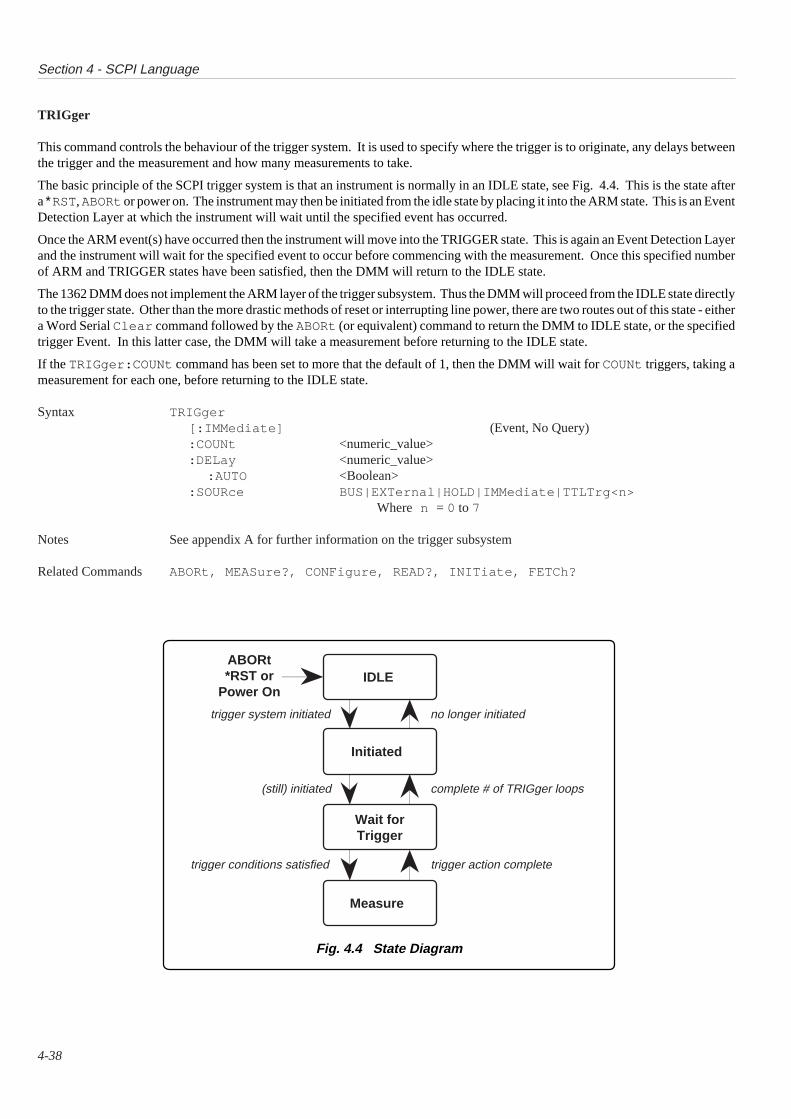
Section 4 - SCPI Language
4-38
Fig. 4.4 State Diagram
TRIGger
This command controls the behaviour of the trigger system. It is used to specify where the trigger is to originate, any delays betweenthe trigger and the measurement and how many measurements to take.
The basic principle of the SCPI trigger system is that an instrument is normally in an IDLE state, see Fig. 4.4. This is the state aftera ∗RST, ABORt or power on. The instrument may then be initiated from the idle state by placing it into the ARM state. This is an EventDetection Layer at which the instrument will wait until the specified event has occurred.
Once the ARM event(s) have occurred then the instrument will move into the TRIGGER state. This is again an Event Detection Layerand the instrument will wait for the specified event to occur before commencing with the measurement. Once this specified numberof ARM and TRIGGER states have been satisfied, then the DMM will return to the IDLE state.
The 1362 DMM does not implement the ARM layer of the trigger subsystem. Thus the DMM will proceed from the IDLE state directlyto the trigger state. Other than the more drastic methods of reset or interrupting line power, there are two routes out of this state - eithera Word Serial Clear command followed by the ABORt (or equivalent) command to return the DMM to IDLE state, or the specifiedtrigger Event. In this latter case, the DMM will take a measurement before returning to the IDLE state.
If the TRIGger:COUNt command has been set to more that the default of 1, then the DMM will wait for COUNt triggers, taking ameasurement for each one, before returning to the IDLE state.
Syntax TRIGger[:IMMediate] (Event, No Query):COUNt <numeric_value>:DELay <numeric_value>
:AUTO <Boolean>:SOURce BUS|EXTernal|HOLD|IMMediate|TTLTrg<n>
Where n = 0 to 7
Notes See appendix A for further information on the trigger subsystem
Related Commands ABORt, MEASure?, CONFigure, READ?, INITiate, FETCh?
Wait forTrigger
ABORt*RST or
Power On
trigger system initiated no longer initiated
(still) initiated complete # of TRIGger loops
trigger conditions satisfied trigger action complete
IDLE
Initiated
Measure
Section 4 - SCPI Language
4-39
TRIGger[:IMMediate]
If the DMM is in the Wait-for-trigger state set by the INITiate command, then the DMM will take a measurement. The measurementscan then be recalled using the FETCh? command. Note that the DMM must be in either TRIG:SOUR BUS or TRIG:SOUR HOLDstate for this command to trigger the DMM and not generate an error.
Errors An error of - 211,'Trigger ignored' will be generated if the DMM has not been initiated with an INITcommand. (Thus from this command the error will be generated if TRIG:SOURce IMM is selected).
Query This is an event and thus cannot be queried.
∗RST On ∗RST the DMM is placed into the Idle state.
TRIGger:COUNt <numeric_value>
This command configures the DMM to expect <numeric_value> triggers and to take a measurement for each trigger and store theminternally. The DMM must be placed in the wait-for-trigger mode. This can be done using the INIT command. The subsequentreadings taken can be recalled with the FETCh? command. Alternatively, the DMM can be placed into the wait-for-trigger state usingthe READ? command. This will then return the subsequent measurements to the output queue when they are taken.
The <numeric_value> must be in the range 1 to 1000 . If MAXimum is sent then the DMM will expect 1000 triggers, If MINimumis sent then the DMM will expect 1 trigger.
Errors An error of - 222,'Data out of range' is generated if <numeric_value> is outside the range 1-1000 .
Query TRIGger:COUNt? [MINimum|MAXimum]This query command returns the current setting of the number of triggers expected. If MINimum is present'1' is returned, if MAXimum is present, then '1000 ' is returned.
∗RST TRIGger:COUNt 1
TRIGger:DELay:AUTO <Boolean>
This command enables or disables the use of default trigger delays. If the value of <Boolean> is 'OFF' or '0' then the default delaysare not used, if <Boolean> is 'ON' or '1' then the defaults are used. If the default delays are deselected the delay between trigger andmeasurement is given by the TRIGger:DELay command.
The default delays are dependent on the current function, range and resolution as set in the 1362 handbook. The default value will changeevery time a new function or range or resolution is selected.
If a TRIGger:DELay <numeric_value> command is received then TRIGger:DELay:AUTO will be turned OFF.
Errors There are no associated errors.
Query TRIGger:DELay:AUTO?This returns either '0' or '1' depending if delays are respectively disabled or enabled.
∗RST TRIGger:DELay:AUTO ON
Section 4 - SCPI Language
4-40
TRIGger:DELay <numeric_value>
This command defines the time delay between a trigger event and the measurement conversion starting. The range of <numeric_value>must be in the range 0 sec to 10 sec. (See 1362 handbook for resolutions). If a value of greater that 10 is received, the DMM willdefault to 10. MINimum will select a value of 0 sec, MAXimum will select 10 sec.
Once a delay is selected, then this will apply to all subsequent measurements.
Errors An error of - 222 'Data out of range' will be reported if the <numeric_value> is less that 0 or greaterthan 10 seconds.
Query TRIGger:DELay? [MINimum|MAXimum]This will return the current setting of the trigger delay. If a default delay is currently active, then this valuewill be returned. If MINimum is present, then '0' will be returned, if MAXimum is present then '10 ' willbe returned.
∗RST As TRIGger:DELay:AUTO ON is selected, then the DMM default delays will be selected.
TRIGger:SOURce BUS|EXTernal|HOLD|IMMediate|TTLTrg<n> (n = 0 to 7)
This command defines the source of the measurement trigger. The following lists the possible parameter options:
Alternative Parameters:BUS This will accept Group Execute Trigger (GET), *TRG.
EXTernal This selects the DMM front panel 'EXT TRIG' connector.
HOLD This deselects all triggers, however the TRIGger:IMMediate command will overridethis 'HOLD' state and cause a measurement to be taken.
IMMediate In this mode, an INIT , READ? or MEAS? command will cause a measurement to be taken.
TTLTrg<n> This selects the backplane TTL VXI trigger system. Note that only one of(n = 0 to 7) these TTLTrg lines can be selected at any one time. If the
OUTPut:TTLTrg<n>:PROTocol ASYNchronous mode is selected, thenTTLTrg1|3|5|7 will generate an error of - 221,'Settings conflict' . Note thatthis command only selects the trigger mode, it does not cause a trigger.
Errors The DMM must be in the idle mode for a TRIGger:SOURce command to be accepted. An execution errorof - 221,'Settings conflict' will be generated if a TRIGger:SOURce command is received whenthe DMM is already in the trigger mode.
If the DMM is in the idle state then any GET or *TRG commands will cause an execution error of -211,'Trigger ignored' . However any triggers on the external or TTL lines will be ignored with noerror.
MEAS? and READ? will generate an error of - 214,'Trigger deadlock' If received while in theTRIGger:SOURce BUS mode.
Query TRIGger:SOURce?This queries the current setting of the trigger mode. it will return one of the following:
'BUS' 'EXT' 'HOLD' 'IMM' 'TTLTn'
∗RST The DMM is initially placed in the idle state with TRIG:SOUR IMM.
--------------------------------------
Native Equivalent BLOCK
Related Commands OUTPut, INITiate .

APPENDIX A to SECTION 41362S SCPI -
Command SummaryError Codes and Messages∗RST (Reset) ConditionsTrigger CombinationsTrigger Timing Information
4-A1

Appendix A to Section 4 - SCPI Language
4-A2
SCPI Command Summary
The following is a table of Command and Query Command codes that have been implemented in the 1362S.
COMMAND FORMAT DESCRIPTION
ABORt Abort current trigger state and return to idle state.
CALibration :HIGH? [<numeric_value>] Perform full scale calibration using the <numeric_value>.:LOW? [<numeric_value>] Performs zero scale calibration using the <numeric>.:SECure <Boolean> Enable the calibration security.:SECure? Query the current setting of the security.:SLFRequency? Store current line frequency in non-volatile stores.
CONFigure<function> <parameter>[,<source_list>] General configuration command.
<function> :CURRent[:DC|:AC Selects Current; respectively DC or AC:FRESistance Selects four wire Ohms.:RESistance Selects two wire Ohms.:VOLTage[:DC]|:AC Selects Voltage; respectively DC or AC.
<parameter> [<expected_value[,<resolution]] Parameters for the <function>.
<source_list> [[,(@1)]|(@2)|(@1,2)|(@1:2)] This selects channel (if option fitted) to be measured.
CONFigure? This returns the current selected function, range andresolution of the DMM.
FETCh? Returns the last set of measurements taken.
INITiate [:IMMediate] Places DMM in the wait for trigger state.
INPut :COUPling AC|DC Selects input coupling source.:COUPling? Queries the state of the input coupling.:FILTer[:LPASs][:STATe]<Boolean> Selects or Deselects the input filter.:FILTer[:LPASs][:STATe]? Query the state of the input filter.GUARd LOW | FLOat Connect the guard to signal low, or allow the guard to float.GUARd? Query the status of the guard connection.[:STATe]<Boolean> Selects input connection or isolation.[:STATe]? Queries the state of the input connection.ZERO? Performs an input zero offset correction.
MEASure <function>?<parameters>[,<source_list>] Configure the DMM and take a measurement and INITiatesthat measurement.
<function> :CURRent[[:DC] | :AC]? Selects Current, either DC or AC:FRESistance Selects four wire Ohms.:RESistance Selects two wire Ohms.:VOLTage[[:DC]|:AC]? Selects voltage, either DC or AC
<parameter> [<expected_value[,<resolution]] Parameters for the <function>.
<source_list> [[,(@1)]|(@2)|(@1,2)|(@1:2)] This selects channel (if option fitted) to be measured.
OUTput :TTLTrg0|1|2|3|4|5|6|7 :PROTocol SYNChronous |ASYNchronousSet the VXI trigger line protocol mode.
:TTLTrg0|1|2|3|4|5|6|7 :PROTocol ? Query the VXI lines protocol.
READ? Places the DMM in a wait for trigger state and then returns themeasurement after the trigger.
[SENSe:] CURRent[:DC] | :AC <parameter> Selects either DC or AC current.CURRent[:DC] | :AC <parameter>? Query the setting current function setting.RESistance | :FRESistance <parameter> Selects either 2 or 4 wire resistance measurement.RESistance | :FRESistance <parameter>? Query the setting resistance setting.VOLTage[:DC]| :AC <parameter> Selects either DC or AC Voltage.VOLTage[:DC]| :AC <parameter>? Query voltage setting.
<parameter> :RANGe<numeric_value> Selects the value expected to be measured.:AUTO<Boolean> Selects Autorange.
:RESolution<numeric value> Selects the resolution for the function selected.MAXimum Selects the maximum resolution for the function selected.:MINimum Selects the minimum resolution for the function selected.:AUTO ON Explicitly setting a value for RESolution will turn Auto:Off.
FILTer[:LPASs][:STATe] <Boolean> Selects or deselects the input filter.FILTer[:LPASs][:STATe]? Query the state of the input filter.LFRequency<numeric_value> Set the integration time related to line frequency setting.LFRequency? Query the line frequency setting.
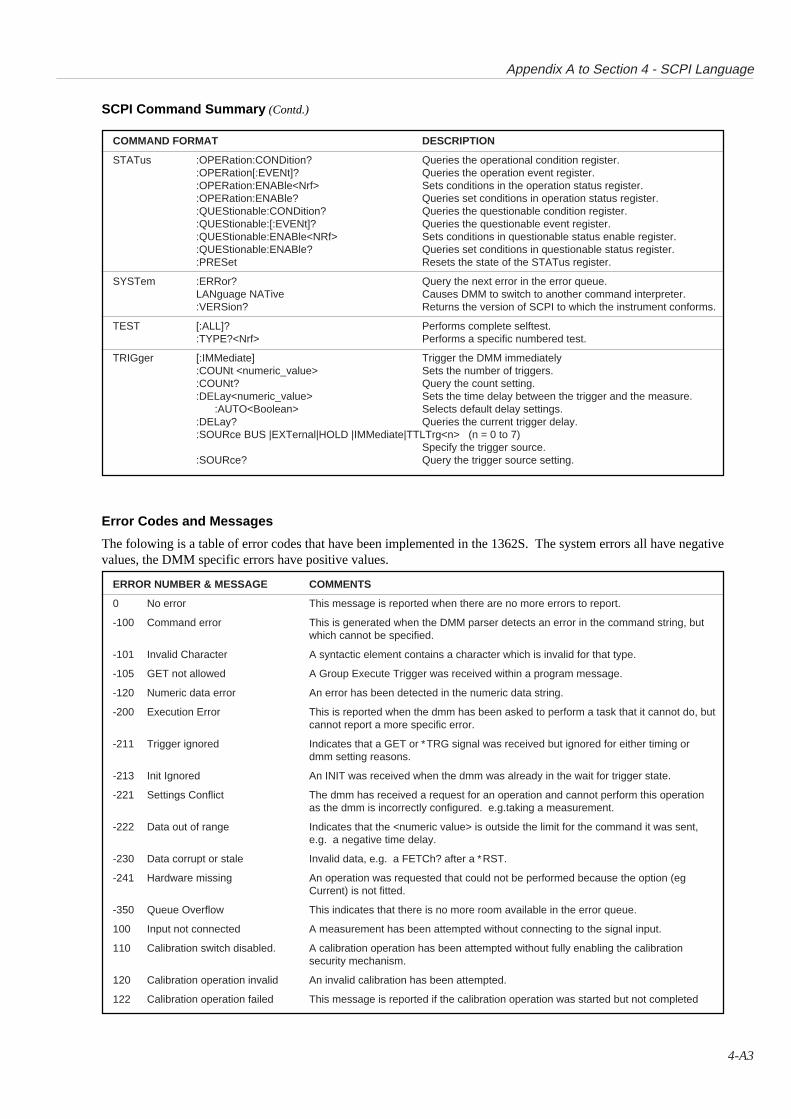
Appendix A to Section 4 - SCPI Language
4-A3
ERROR NUMBER & MESSAGE COMMENTS
0 No error This message is reported when there are no more errors to report.
-100 Command error This is generated when the DMM parser detects an error in the command string, butwhich cannot be specified.
-101 Invalid Character A syntactic element contains a character which is invalid for that type.
-105 GET not allowed A Group Execute Trigger was received within a program message.
-120 Numeric data error An error has been detected in the numeric data string.
-200 Execution Error This is reported when the dmm has been asked to perform a task that it cannot do, butcannot report a more specific error.
-211 Trigger ignored Indicates that a GET or ∗TRG signal was received but ignored for either timing ordmm setting reasons.
-213 Init Ignored An INIT was received when the dmm was already in the wait for trigger state.
-221 Settings Conflict The dmm has received a request for an operation and cannot perform this operationas the dmm is incorrectly configured. e.g.taking a measurement.
-222 Data out of range Indicates that the <numeric value> is outside the limit for the command it was sent,e.g. a negative time delay.
-230 Data corrupt or stale Invalid data, e.g. a FETCh? after a ∗RST.
-241 Hardware missing An operation was requested that could not be performed because the option (egCurrent) is not fitted.
-350 Queue Overflow This indicates that there is no more room available in the error queue.
100 Input not connected A measurement has been attempted without connecting to the signal input.
110 Calibration switch disabled. A calibration operation has been attempted without fully enabling the calibrationsecurity mechanism.
120 Calibration operation invalid An invalid calibration has been attempted.
122 Calibration operation failed This message is reported if the calibration operation was started but not completed
SCPI Command Summary (Contd.)
Error Codes and Messages
The folowing is a table of error codes that have been implemented in the 1362S. The system errors all have negativevalues, the DMM specific errors have positive values.
COMMAND FORMAT DESCRIPTION
STATus :OPERation:CONDition? Queries the operational condition register.:OPERation[:EVENt]? Queries the operation event register.:OPERation:ENABle<Nrf> Sets conditions in the operation status register.:OPERation:ENABle? Queries set conditions in operation status register.:QUEStionable:CONDition? Queries the questionable condition register.:QUEStionable:[:EVENt]? Queries the questionable event register.:QUEStionable:ENABle<NRf> Sets conditions in questionable status enable register.:QUEStionable:ENABle? Queries set conditions in questionable status register.:PRESet Resets the state of the STATus register.
SYSTem :ERRor? Query the next error in the error queue.LANguage NATive Causes DMM to switch to another command interpreter.:VERSion? Returns the version of SCPI to which the instrument conforms.
TEST [:ALL]? Performs complete selftest.:TYPE?<Nrf> Performs a specific numbered test.
TRIGger [:IMMediate] Trigger the DMM immediately:COUNt <numeric_value> Sets the number of triggers.:COUNt? Query the count setting.:DELay<numeric_value> Sets the time delay between the trigger and the measure.
:AUTO<Boolean> Selects default delay settings.:DELay? Queries the current trigger delay.:SOURce BUS |EXTernal|HOLD |IMMediate|TTLTrg<n> (n = 0 to 7)
Specify the trigger source.:SOURce? Query the trigger source setting.
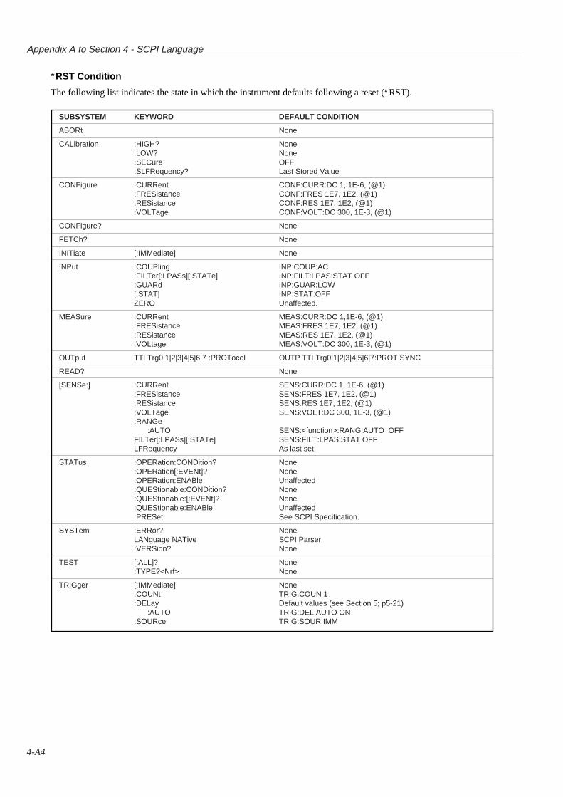
Appendix A to Section 4 - SCPI Language
4-A4
SUBSYSTEM KEYWORD DEFAULT CONDITION
ABORt None
CALibration :HIGH? None:LOW? None:SECure OFF:SLFRequency? Last Stored Value
CONFigure :CURRent CONF:CURR:DC 1, 1E-6, (@1):FRESistance CONF:FRES 1E7, 1E2, (@1):RESistance CONF:RES 1E7, 1E2, (@1):VOLTage CONF:VOLT:DC 300, 1E-3, (@1)
CONFigure? None
FETCh? None
INITiate [:IMMediate] None
INPut :COUPling INP:COUP:AC:FILTer[:LPASs][:STATe] INP:FILT:LPAS:STAT OFF:GUARd INP:GUAR:LOW[:STAT] INP:STAT:OFFZERO Unaffected.
MEASure :CURRent MEAS:CURR:DC 1,1E-6, (@1):FRESistance MEAS:FRES 1E7, 1E2, (@1):RESistance MEAS:RES 1E7, 1E2, (@1):VOLtage MEAS:VOLT:DC 300, 1E-3, (@1)
OUTput TTLTrg0|1|2|3|4|5|6|7 :PROTocol OUTP TTLTrg0|1|2|3|4|5|6|7:PROT SYNC
READ? None
[SENSe:] :CURRent SENS:CURR:DC 1, 1E-6, (@1):FRESistance SENS:FRES 1E7, 1E2, (@1):RESistance SENS:RES 1E7, 1E2, (@1):VOLTage SENS:VOLT:DC 300, 1E-3, (@1):RANGe
:AUTO SENS:<function>:RANG:AUTO OFFFILTer[:LPASs][:STATe] SENS:FILT:LPAS:STAT OFFLFRequency As last set.
STATus :OPERation:CONDition? None:OPERation[:EVENt]? None:OPERation:ENABle Unaffected:QUEStionable:CONDition? None:QUEStionable:[:EVENt]? None:QUEStionable:ENABle Unaffected:PRESet See SCPI Specification.
SYSTem :ERRor? NoneLANguage NATive SCPI Parser:VERSion? None
TEST [:ALL]? None:TYPE?<Nrf> None
TRIGger [:IMMediate] None:COUNt TRIG:COUN 1:DELay Default values (see Section 5; p5-21)
:AUTO TRIG:DEL:AUTO ON:SOURce TRIG:SOUR IMM
∗RST Condition
The following list indicates the state in which the instrument defaults following a reset (∗RST).
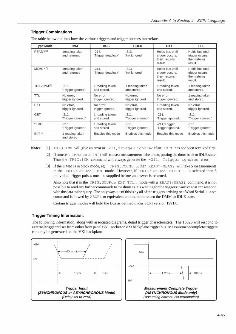
Appendix A to Section 4 - SCPI Language
4-A5
Type\Mode IMM BUS HOLD EXT TTL
READ? [3] 1reading taken -214, -213, Holds bus until Holds bus untiland returned 'Trigger deadlock' 'Init ignored' trigger occurs, trigger occurs,
then returns then returnsresult. result.
MEAS? [3] 1reading taken -214, -213, Holds bus until Holds bus untiland returned 'Trigger deadlock' 'Init ignored' trigger occurs, trigger occurs,
then returns then returnsresult. result.
TRIG:IMM [2] -211, 1 reading taken 1 reading taken 1 reading taken 1 reading taken'Trigger ignored.' and stored. and stored. and stored. and stored.
TTL No error, No error, No error, No error, 1 reading takentrigger ignored. trigger ignored. trigger ignored. trigger ignored. and stored.
EXT No error, No error, No error, 1 reading taken No errortrigger ignored. trigger ignored. trigger ignored. and stored. trigger ignored.
GET -211, 1 reading taken -211, -211, -211,'Trigger ignored.' and stored. 'Trigger ignored.' 'Trigger ignored. 'Trigger ignored.'
∗TRG -211, 1 reading taken -211, -211,'Trigger -211,'Trigger ignored.' and stored. 'Trigger ignored.' 'Trigger ignored.' 'Trigger ignored.'
INIT [1] 1 reading taken Enables this mode Enables this mode Enables this mode Enables this modeand stored.
Trigger Combinations
The table below outlines how the various triggers and trigger sources interrelate.
Trigger Timing Information.
The following information, along with associated diagrams, detail trigger characteristics. The 1362S will respond toexternal trigger pulses from either front panel BNC socket or VXI backplane trigger bus. Measurement complete triggerscan only be generated on the VXI backplane.
Notes: [1] TRIG:IMM will give an error or -211,Trigger ignored if an INIT has not been received first.
[2] If source is IMM , then an INIT will cause a measurement to be taken, putting the dmm back to IDLE state.Thus the TRIG:IMM command will always generate the -211, Trigger ignored error.
[3] If the DMM is in block mode, eg. TRIG:COUNt 5 , then READ?/MEAS? will take 5 measurementsin the TRIG:SOURce IMM mode. However, if TRIG:SOURce EXT|TTL is selected then 5individual trigger pulses must be supplied before an answer is returned.
Also note that if in the TRIG:SOURce EXT|TTLn mode with a READ?/MEAS? command, it is notpossible to send any further commands to the dmm as it is waiting for the triggers to arrive so it can respondwith the data to the query. The only way out of this is by all of the triggers arriving or a Word Serial Clearcommand followed by ABORt or equivalent command to return the DMM to IDLE state.
Certain trigger modes will hold the Bus as defined under SCPI version 1991.0.
Measurement Complete Trigger(ASYNCHRONOUS Mode only)
(Assuming correct VXI termination)
Trigger Input(SYNCHRONOUS or ASYNCHRONOUS Mode)
(Delay set to zero)
10µs
40ns min
+5V
0V
SIG
+5V
0V
SIG
1.2ms 200µs

this page deliberately left blank

SECTION 51362 NATIVE LANGUAGE
IEEE 488.2 COMMAND SYNTAX
5-1
Section 5 - Native Language
5-2
SECTION 5 1362 NATIVE LANGUAGE -IEEE 488.2 COMMAND SYNTAX
IEEE 488.2 Programming Language
IEEE 488.2 Syntax Diagrams in this SectionThe following notations decribe the syntax diagrams used in this handbook.
Notation• Syntactic elements are connected by lines with directional
symbols to indicate the flow, which generally proceeds fromleft to right.
• Repeatable elements have a right-to-left reverse path shownaround and above them, which can also contain a separatorsuch as a comma.
• When it is possible to bypass elements, a left-to-right path isshown around and below them.
• When there is a choice of elements, the path branches to thechoices.
Hierarchy of Syntactic ElementsMessages are characterized by the presence of terminators, each ofwhich seals the set of syntactic elements sent since the previousterminator to form a ‘Program Message’.
VXI WSC and EffectsThe VXI Word Serial 'clear' Message will force the followinginstrument states:
• the input buffer and output queue are cleared;• parser is reset to the beginning of a message;• any device-dependent message interlocks are cleared.
This command will not:
• change any settings or stored data within the instrumentexcept as listed above;
• interrupt analog input;• interrupt or affect any functions of the device;• change the status byte.
∗RST and EffectsThe effects of the ∗RST command are described later on page 5-39.
ResetA complete instrument reset is accomplished by the two resetcommands in sequence. In other circumstances they may be usedindividually:
WS clear Message exchange initialization;*RST Device initialization.
IntroductionAs the instrument has to operate on the VXI bus, it is not in directcontact with the outside world and cannot conform fully to theIEEE 488.1 Hardware model. For example, in the IEEE 488.1model, a separate (SRQ) line is provided for the instrument torequest service from the controller.
A separate line for requesting service is not provided on the VXIbus, and to provide a similar facility, the VXI ‘request true’ syntaxhas to be programmed in software; thus a hardware differenceimposes a departure from the standard programming model. Apartfrom such external constraints, the 1362 ‘Native Language’conforms to the syntax rules of the IEEE 488.2 Standardprogramming model.
IEEE 488.2 defines sets of Mandatory Common Commands andOptional Common Commands along with a method of StandardStatus Reporting. The 1362 conforms with all MandatoryCommands but not all Optional Commands, and conforms with thedefined Status Reporting method.Note: Commands prefaced by asterisk, (eg: ∗TRG) are standard-defined ‘Common’ commands.
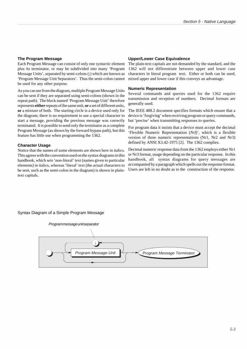
Section 5 - Native Language
5-3
Syntax Diagram of a Simple Program Message
Program message unit separator
The Program MessageEach Program Message can consist of only one syntactic elementplus its terminator, or may be subdivided into many ‘ProgramMessage Units’, separated by semi-colons (;) which are known as‘Program Message Unit Separators’. Thus the semi-colon cannotbe used for any other purpose.
As you can see from the diagram, multiple Program Message Unitscan be sent if they are separated using semi-colons (shown in therepeat path). The block named ‘Program Message Unit’ thereforerepresents either repeats of the same unit, or a set of different units,or a mixture of both. The starting circle is a device used only forthe diagram; there is no requirement to use a special character tostart a message, providing the previous message was correctlyterminated. It is possible to send only the terminator as a completeProgram Message (as shown by the forward bypass path), but thisfeature has little use when programming the 1362.
Character UsageNotice that the names of some elements are shown here in italics.This agrees with the convention used on the syntax diagrams in thishandbook, which sets ‘non-literal’ text (names given to particularelements) in italics, whereas ‘literal’ text (the actual characters tobe sent, such as the semi-colon in the diagram) is shown in plain-text capitals.
Upper/Lower Case EquivalenceThe plain-text capitals are not demanded by the standard, and the1362 will not differentiate between upper and lower casecharacters in literal program text. Either or both can be used,mixed upper and lower case if this conveys an advantage.
Numeric RepresentationSeveral commands and queries used for the 1362 requiretransmission and reception of numbers. Decimal formats aregenerally used.
The IEEE 488.2 document specifies formats which ensure that adevice is ‘forgiving’ when receiving program or query commands,but ‘precise’ when transmitting responses to queries.
For program data it insists that a device must accept the decimal‘Flexible Numeric Representation (Nrf)’, which is a flexibleversion of three numeric representations (Nr1, Nr2 and Nr3)defined by ANSI X3.42-1975 [2]. The 1362 complies.
Decimal numeric response data from the 1362 employs either Nr1or Nr3 format, usage depending on the particular response. In thishandbook, all syntax diagrams for query messages areaccompanied by a paragraph which spells out the response format.Users are left in no doubt as to the construction of the response.
Program Message Unit Program Message Terminator
;
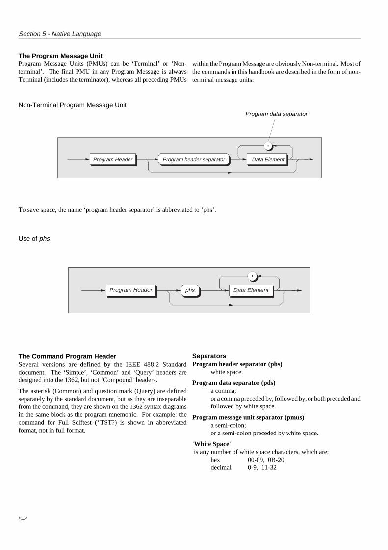
Section 5 - Native Language
5-4
The Program Message UnitProgram Message Units (PMUs) can be ‘Terminal’ or ‘Non-terminal’. The final PMU in any Program Message is alwaysTerminal (includes the terminator), whereas all preceding PMUs
The Command Program HeaderSeveral versions are defined by the IEEE 488.2 Standarddocument. The ‘Simple’, ‘Common’ and ‘Query’ headers aredesigned into the 1362, but not ‘Compound’ headers.
The asterisk (Common) and question mark (Query) are definedseparately by the standard document, but as they are inseparablefrom the command, they are shown on the 1362 syntax diagramsin the same block as the program mnemonic. For example: thecommand for Full Selftest (∗TST?) is shown in abbreviatedformat, not in full format.
SeparatorsProgram header separator (phs)
white space.
Program data separator (pds)a comma;or a comma preceded by, followed by, or both preceded andfollowed by white space.
Program message unit separator (pmus)a semi-colon;or a semi-colon preceded by white space.
'White Space' is any number of white space characters, which are:
hex 00-09, 0B-20decimal 0-9, 11-32
Non-Terminal Program Message Unit
Use of phs
within the Program Message are obviously Non-terminal. Most ofthe commands in this handbook are described in the form of non-terminal message units:
Data Element
,
Program Header phs
To save space, the name ‘program header separator’ is abbreviated to ‘phs’.
Program data separator
Data Element
,
Program Header Program header separator
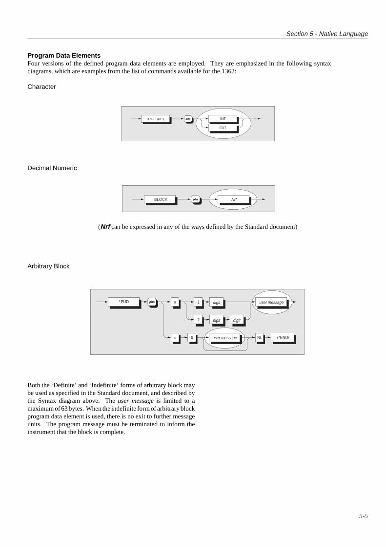
Section 5 - Native Language
5-5
Arbitrary Block
Both the ‘Definite’ and ‘Indefinite’ forms of arbitrary block maybe used as specified in the Standard document, and described bythe Syntax diagram above. The user message is limited to amaximum of 63 bytes. When the indefinite form of arbitrary blockprogram data element is used, there is no exit to further messageunits. The program message must be terminated to inform theinstrument that the block is complete.
Program Data ElementsFour versions of the defined program data elements are employed. They are emphasized in the following syntaxdiagrams, which are examples from the list of commands available for the 1362:
Character
Decimal Numeric
(Nrf can be expressed in any of the ways defined by the Standard document)
TRG_SRCE INTphs
EXT
BLOCK phs Nrf
∗PUD #
# 0
1
2
digit user message
user message
digit digit
/^END/NL
phs

Section 5 - Native Language
5-6
1362 Functions and FacilitiesThe 1362 Functions and Facilities block contains all the device-specific functions and features of the 1362, accepting ExecutableMessage Elements from Execution Control and performing theassociated operations. It responds to any of the elements which arevalid Query Requests (both IEEE 488.2 Common QueryCommands and 1362 Device-specific Commands) by sending anyrequired Response Data to the Response Formatter (after carryingout the assigned internal operations).
Device-dependent errors are detected in this block. Bit 3 (DDE)of the Standard-defined Event Status register is set true when aninternal operating fault is detected, for instance during a self test.Each reportable error has a listed number, which is appended to anassociated queue as the error occurs.
Trigger ControlTwo types of message are used to trigger the 1362 A-D into takinga measurement:
A Word Serial 'trigger'∗TRG (IEEE 488.2-defined)
In the 1362 either message is passed through the Input Buffer,receiving the same treatment as a program message unit, beingparsed and executed as normal.
Outgoing ResponsesThe Response Formatter derives its information from ResponseData (being supplied by the Functions and Facilities block) andvalid Query Requests. From these it builds Response MessageElements, which are placed as a Response Message into the OutputQueue.
The Output Queue acts as a store for outgoing messages until theyare read over the system bus by the application program. For aslong as the output queue holds one or more bytes, it reports the factby setting true bit 4 (Message Available - MAV) of the Status Byteregister. Bit 4 is set false when the output queue is empty (refer tothe sub-section ‘Retrieval of Device Status Information’). The'DOR' bit set performs the same action. Refer to Section 3.
‘Query Error’This is an indication that the controller is following aninappropriate message exchange protocol, resulting in theInterrupted, Unterminated or Deadlocked condition:
Refer to 'Bit 2' on page 5-12.
The Standard document defines the 1362’s response, part of whichis to set true bit 2 (QYE) of the Standard-defined Event Statusregister.
IEEE 488.2 ModelThe IEEE 488.2 Standard document illustrates its MessageExchange Control Interface model at the detail level required bythe device designer. Much of the information at this level ofinterpretation (such as the details of the internal signal paths etc.)is transparent to the application programmer. However, becauseeach of the types of errors flagged in the Event Status Register arerelated to a particular stage in the process, a simplified 1362interface model can provide helpful background. This isillustrated in Fig. 5.1, together with brief descriptions of the actionsof its functional blocks.
1362 Message Exchange ModelInput/Output Control transfers messages from the 1362 outputqueue to the system bus; and conversely from the bus to either theinput buffer, or other predetermined destinations within the deviceinterface. It receives the Status Byte from the status reportingsystem, as well as the state of the Request Service bit which itimposes on bit 6 of the Status Byte response. Bit 6 reflects the‘Request Service state true’ condition of the interface.
Incoming Commands and QueriesThe Input Buffer is a first in - first out queue, which has amaximum capacity of 128 bytes (characters). Each incomingcharacter in the I/O Control generates an interrupt to the instrumentprocessor which places it in the Input Buffer for examination by theParser. The characters are removed from the buffer and translatedwith appropriate levels of syntax checking. If the rate ofprogramming is too fast for the Parser or Execution Control, thebuffer will progressively fill up. When the buffer is full, the VXICommander is informed by DIR being false. Refer to Section 3.
The Parser checks each incoming character and its messagecontext for correct Standard-defined generic syntax, and correctdevice-defined syntax. Offending syntax is reported as aCommand Error , by setting true bit 5 (CME) of the Standard-defined Event Status register (refer to the sub-section ‘Retrieval ofDevice Status Information’).
Execution Control receives successfully parsed messages, andassesses whether they can be executed, given the currently-programmed state of the 1362 functions and facilities. If a messageis not viable (eg the calibration trigger: CALL? when calibrationis not enabled); then an Execution Error is reported, by setting truebit 4 (EXE) of the Standard-defined Event Status register. Viablemessages are executed in order, altering the 1362 functions,facilities etc. Execution does not ‘overlap’ commands; instead,the 1362 Execution Control processes all commands‘Sequentially’ (ie. waits for actions resulting from the previouscommand to complete before executing the next).
Message Exchange

Section 5 - Native Language
5-7
Request Service (RQS)
Reasons for Requesting ServiceThere are two main reasons for the application program to requestservice from the controller:
• When the 1362 message exchange interface discovers a systemprogramming error;
• When the 1362 is programmed to report significant events byRQS.
The significant events vary between types of devices; thus there isa class of events which are known as ‘Device-Specific’. These aredetermined by the device designer.
IEEE 488.2 ModelThe application programmer can enable or disable the event(s)which are required to originate an RQS at particular stages of theapplication program. The IEEE 488.2 model incorporates aflexible extended status reporting structure in which therequirements of the device designer and application programmerare both met.
This structure is described in the next sub-section, dealing with‘Retrieval of Device Status Information’.
VXIbus
BusMessages
1362 BusTransmissions
General and AddressedBus Messages
OutputFormatter
OutputQueue
MessageExchange
Control
InputBuffer
Parser
ExecutionControl
1362 Functionsand Facilities
Input/Output Control
ReceivedMessageElements
ParsedMessageElements
ExecutableMessageElements
ResponseMessageElements
ResponseData
RequestedBus Messages
CommandErrors
(CME bit)
ExecutionErrors
(EXE bit)
Device-DependentErrors (DDE bit)
Query Errors(QYE bit)
MessageAvailable(MAV bit)
Status Byte(STB)
RQS bit state for Status Byte
Power On(PON bit)
(URQ bit)
VXIbus Interface
Filter out bus management and configuration commands
Fig. 5.1 1362 Message Exchange Model

Section 5 - Native Language
5-8
Retrieval of Device Status Information
Introduction
For any remotely-operated system, the provision of up-to-dateinformation about the performance of the system is of majorimportance. This is particularly so in the case of systems whichoperate under automatic control, as the controller requires thenecessary information feedback to enable it to progress theprogrammed task, and any break in the continuity of the processcan have serious results.
When developing an application program, the programmer needsto test and revise it, knowing its effects. Confidence that theprogram elements are couched in the correct grammar and syntax(and that the program commands and queries are thus beingaccepted and acted upon), helps to reduce the number of iterationsneeded to confirm and develop the viability of the whole program.So any assistance which can be given in closing the informationloop must benefit both program compilation and subsequent use.
Note : The registers use binary weighting - the numbers in the boxes are bit numbers, not weighted values
0MSS
ESB MAVSTATUS BYTEREGISTER
Request for Service BitMaster Status Summary Bit
Event Status Summary Bit
Message Available Bit
AAAAAAAAAAAAAAAAAAAAAAAAAA
Service RequestEnable Register
7 6 5 4 3 2 1 0PON URQ CME OPCEXE DDE QYE
Query Error
Power On
User Request
Command Error
Execution Error
Device Dependent Error
Operation Complete
Standard-Defined EventStatus Register
RQC
RequestControl
Not usedon 1362
AAAAAA
AAAAAA
AAAAAA
AAAAAA
AAAAAA
AAAAAAAA
AAAAAAAA
AAAAAA
EventStatus Enable Register
76
5 4 3 2 1
RQS
∗ SRE phs Nrf
∗ SRE?
∗ STB?
∗ ESE phs Nrf
∗ ESE?
∗ ESR?
Fig. 5.2 1362 Status Reporting Structure
Section 5 - Native Language
5-9
Standard-Defined Features
Types of Status Information AvailableTwo main categories of information are provided for thecontroller:
Status Summary InformationCertain standard events are flagged in the 8-bit latched ‘EventStatus Register’ (ESR), read-accessible to the controller. Theuser’s application program can also access its associated enablingregister, to program the events which will be eligible to activate the'ESB' summary bit in the Status Byte.
Status Byte RegisterContained within the ‘Status Byte Register’, the ‘Status Byte’(STB) consists of three flag bits which direct the controller’sattention to the type of event which has occurred. One is the ESBbit mentioned above, the other two (MAV and MSS) are describedin detail later.
Access via the Application ProgramThe application designer has access to two enable registers (one foreach main register - Fig. 5-2). The application program can enableor disable any individual bit in these registers.
Each bit in the event status register remains in false conditionunless its assigned event occurs, when its condition changes totrue. If an event is to be reported, the application program sets itscorresponding enable bit true, using the number Nrf (defined as adecimal numeric from 0 to 255 in any common format). Thenwhen the enabled event occurs and changes the enabled bit fromfalse to true, the ESB summary bit in the Status Byte is also set true.If the ESB bit is also enabled, then the 1362 will generate a requesttrue event on the VXI bus.
Thus the application programmer can decide which assignedevents will generate an event, by enabling their event bits and thenenabling the ESB bit in the Status Byte. The application programcan read the Status Byte, and be directed to the Event Register todiscover which event was responsible for originating the request.
All registers can be read by suitable commands, as an ASCIIdecimal numeric, which when expressed in binary, represents thebit pattern in the register. This form is also used to set the enablingregisters to the required bit-patterns. The detail for each register isexpanded in the following paragraphs, and in the commanddescriptions.
Section 5 - Native Language
5-10
1362 Status Reporting - Detail
IEEE 488.2 ModelThis incorporates the two aspects of the IEEE 488.1 model into anextended structure with more definite rules. These rules invoke theuse of standard ‘Common’ messages and provide for device-dependent messages. A feature of the structure is the use of ‘Event’registers, each with its own enabling register as illustrated in Fig.5.2.
1362 Model StructureThe IEEE 488.2 Standard provides for an extensive hierarchicalstructure with the Status Byte at the apex, defining its bits 4, 5 and6 and their use as summaries of a Standard-defined event structurewhich must be included, if the device is to claim conformance withthe Standard. The 1362 employs these bits as defined in theStandard.
Bits 0, 1, 2 and 3 and 7 are made available to the device designer,but are not used in the 1362.
It must be recognized by the application programmer thatwhenever the controller reads the Status Byte, it can only receivesummaries of types of events, and further query messages arenecessary to dig deeper into the detailed information relating to theevents themselves. Thus a further byte is used to expand on thesummary at bit 5 of the Status Byte.
Status Byte RegisterIn this structure the Status Byte is held in the ‘Status ByteRegister’; the bits being allocated as follows:
Bits 0 (DIO1), 1 (DIO2), 2 (DIO3) and 3 (DIO4) are not used in the1362 status byte. They are always false.
Bit 4 (DIO5) IEEE 488.2-defined Message Available Bit(MAV)
The MAV bit helps to synchronize information exchange with thecontroller. It is true when the 1362 message exchange interface isready to accept a request from the controller to start outputtingbytes from the Output Queue; or false when the Output Queue isempty.
The common command ∗CLS can clear the Output Queue, and theMAV bit 4 of the Status Byte Register; providing it is sentimmediately following a ‘Program Message Terminator’.
Bit 5 (DIO6) IEEE 488.2-defined Standard Event SummaryBit (ESB)
Summarizes the state of the ‘Event Status byte’, held in the ‘EventStatus register’ (ESR), whose bits represent IEEE 488.2-definedconditions in the device. The ESB bit is true when the byte in theESR contains one or more enabled bits which are true; or falsewhen all the enabled bits in the byte are false. The byte, the EventStatus Register and its enabling register are defined by the IEEE488.1 Standard; they are described later.
Bit 6 (DIO7) is the Master Status Summary Message (MSS bit),and is set true if one of the bits 0 to 4 or bit 5 is true (bits 0 to 3 andbit 7 are always false in the 1362).
Bit 7 (DIO8) is not used in the 1362 status byte. It is always false.
Reading the Status Byte Register∗STB?Either the common query: ∗STB?, or the VXI word serial 'readSTB' command (Section 3), reads the binary number in the StatusByte register. The response is in the form of a decimal numberwhich is the sum of the binary weighted values in the enabled bitsof the register. In the 1362, the binary-weighted values of bits 1,2, 3 and 7 are always zero.
Section 5 - Native Language
5-11
The SRE register is a means for the application program to select,by enabling individual Status Byte summary bits, those types ofevents which are to cause the 1362 to originate an RQS. It containsa user-modifiable image of the Status Byte, whereby each true bitacts to enable its corresponding bit in the Status Byte.
Bit Selector: ∗SRE phs NrfThe program command: ∗SRE phs Nrf performs the selection,where Nrf is a decimal numeric, which when decoded into binaryproduces the required bit-pattern in the enabling byte.
For example:If an RQS is required only when a Standard-defined eventoccurs and when a message is available in the output queue,then Nrf should be set to 48. The binary decode is 00110000so bit 4 or bit 5, when true, will generate an RQS; but even whenbit 0 or bit 6 is true, no RQS will result. The 1362 always setsthe Status Byte bits 1, 2, 3 and 7 false, so they can neveroriginate an RQS whether enabled or not.
Reading the Service Request Enable RegisterThe common query: ∗SRE? reads the binary number in the SREregister. The response is in the form of a decimal number whichis the sum of the binary-weighted values in the register. Thebinary-weighted values of bits 1, 2, 3 and 7 are always zero.
VXIbus ImplementationAn RQS is implemented as a 'request true' event on the VXIbus.Refer to Section 3.
Service Request Enable Register
Section 5 - Native Language
5-12
IEEE 488.2-defined Event Status RegisterThe ‘Event Status Register’ holds the Event Status Byte,consisting of event bits, each of which directs attention toparticular information. All bits are ‘sticky’; ie. once true, cannotreturn to false until the register is cleared. This occursautomatically when it is read by the query: ∗ESR?. The commoncommand ∗CLS clears the Event Status Register and associatederror queues, but not the Event Status Enable Register. The bits arenamed in mnemonic form as follows:
Bit 0 Operation Complete (OPC)This bit is true only if ∗OPC has been programmed and all selectedpending operations are complete. As the 1362 operates in serialmode, its usefulness is limited to registering the completion of longoperations, such as self-test.
Bit 1 Request Control (RQC)This bit would be true if the device were able to assume the role ofcontroller, and is requesting that control be transferred to it fromthe current controller. This capability is not available in the 1362,so bit 1 is always false.
Bit 2 Query Error (QYE)QYE true indicates that the controller is following an inappropriatemessage exchange protocol, resulting in the following situations:
• Interrupted Condition. When the 1362 has not finishedoutputting its Response Message to a Program Query, and isinterrupted by a new Program Message.
• Unterminated Condition. When the controller attempts toread a Response Message from the 1362 without having firstsent the complete Query Message (including the ProgramMessage Terminator) to the instrument.
• Deadlocked Condition. When the input and output buffers arefilled, with the parser and the execution control blocked.
Bit 3 Device Dependent Error (DDE)DDE is set true when an internal operating fault is detected, forinstance during a self test. Each reportable error has been given alisted number, which is appended to an associated queue as theerror occurs. The queue is read destructively as a First In Last Outstack, using the query command DDQ? to obtain a code number.The DDE bit is not a summary of the contents of the queue, but isset or confirmed true concurrent with each error as it occurs; andonce cleared by ∗ESR? will remain false until another error occurs.The query DDQ? can be used to read all the errors in the queue untilit is empty, when the code number zero will be returned.The common command ∗CLS clears the queue.
Bit 4 Execution Error (EXE)An execution error is generated if the received command cannot beexecuted, owing to the device state or the command parameterbeing out of bounds.
Bit 5 Command Error (CME)CME occurs when a received bus command does not satisfy theIEEE 488.2 generic syntax or the device command syntaxprogrammed into the instrument interface’s parser, and so is notrecognized as a valid command.
Bit 6 User Request (URQ)This bit is set true when, in block measurement mode, the numberof measurements programmed for the block measurement havebeen completed.
Bit 7 1362 Power Supply On (PON)This bit is not required in the VXI subsystem.

Section 5 - Native Language
5-13
Standard Event Status Enable RegisterThe ESE register is a means for the application program to select,from the positions of the bits in the standard-defined Event StatusByte, those events which when true will set the ESB bit true in theStatus Byte. It contains a user-modifiable image of the standardEvent Status Byte, whereby each true bit acts to enable itscorresponding bit in the standard Event Status Byte.
Bit Selector: ∗ESE phs NrfThe program command: ∗ESE phs Nrf performs the selection,where Nrf is a decimal numeric, which when decoded into binary,produces the required bit-pattern in the enabling byte.
For example:If the ESB bit is required to be set true only when an executionor device-dependent error occurs, then Nrf should be set to 24.The binary decode is 00011000 so bit 3 or bit 4, when true, willset the ESB bit true; but when bits 0-2, or 5-7 are true, the ESBbit will remain false.
Reading the Standard Event Enable RegisterThe common query: ∗ESE? reads the binary number in the ESEregister. The response is in the form of a decimal number whichis the sum of the binary-weighted values in the register.

Section 5 - Native Language
5-14
1362 Native Language - IEEE 488.2 Command Syntax Diagrams
Select DC Voltage measurement mode, range, filter and accuracy
AUTO selects the autorange facility.When in AUTO, the DMM attempts to select the most appropriaterange, moving up-range on overload and down-range on less than18% of range. If there is still an overload on the 300V range, thena measurement error will be generated.
A valid Nrf deselects the AUTO mode.
Note: On exit from this function the states of the range, filter andresolution are stored.
On return to this function, these settings are recalled andused as default unless explicitly specified.
FILT1 inserts the analog filter.The NMRR is 74dB @ 50Hz/60Hz ±0.1%.
FILTØ removes the analog filter.The NMRR is 54dB @ 50Hz/60Hz ±0.1%.
RESL4 sets resolution and A-D performance to 4.5 digits.
RESL5 sets resolution and A-D performance to 5.5 digits.
RESL6 sets resolution and A-D performance to 6.5 digits.
At Power On or Reset ; the default:DCV (300V) RESL6 FILTØ
is selected and active.
Nrf is a decimal numeric value used to select the range.Thus for a modulus value of Nrf:
Ø to Ø.1999999 selects the 100mV range.Ø.2 to 1.999999 selects the 1V range.2.Ø to 19.99999 selects the 10V range.2Ø to 199.9999 selects the 100V range>2ØØ selects the 300V range.
Excessive digits in Nrf are rounded to 6.5 digits.
,DCV Nrf
AUTO
FILT0
FILT1
RESL5
RESL6
phs
,
RESL4
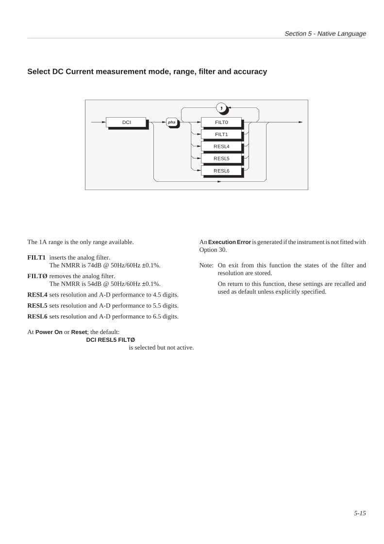
Section 5 - Native Language
5-15
Select DC Current measurement mode, range, filter and accuracy
An Execution Error is generated if the instrument is not fitted withOption 30.
Note: On exit from this function the states of the filter andresolution are stored.
On return to this function, these settings are recalled andused as default unless explicitly specified.
The 1A range is the only range available.
FILT1 inserts the analog filter.The NMRR is 74dB @ 50Hz/60Hz ±0.1%.
FILTØ removes the analog filter.The NMRR is 54dB @ 50Hz/60Hz ±0.1%.
RESL4 sets resolution and A-D performance to 4.5 digits.
RESL5 sets resolution and A-D performance to 5.5 digits.
RESL6 sets resolution and A-D performance to 6.5 digits.
At Power On or Reset ; the default:DCI RESL5 FILTØ
is selected but not active.
DCI
,FILT0
FILT1
RESL4
RESL5
RESL6
phs
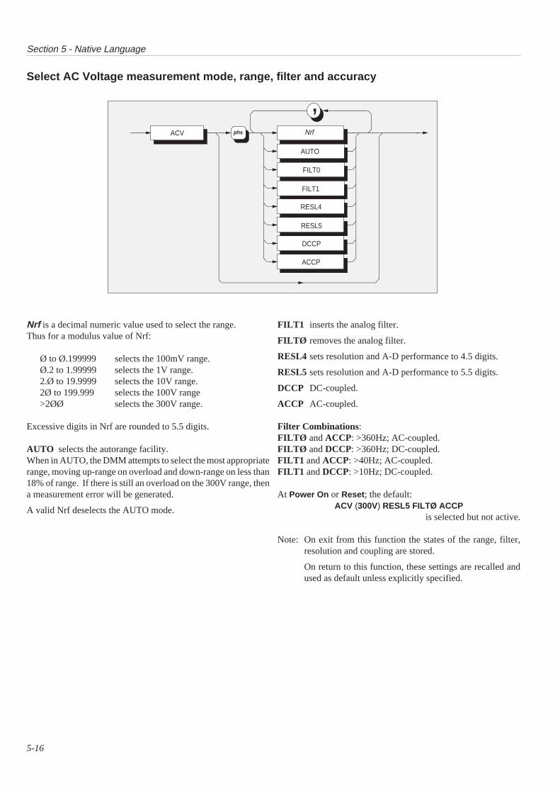
Section 5 - Native Language
5-16
Select AC Voltage measurement mode, range, filter and accuracy
FILT1 inserts the analog filter.
FILTØ removes the analog filter.
RESL4 sets resolution and A-D performance to 4.5 digits.
RESL5 sets resolution and A-D performance to 5.5 digits.
DCCP DC-coupled.
ACCP AC-coupled.
Filter Combinations:FILTØ and ACCP: >360Hz; AC-coupled.FILTØ and DCCP: >360Hz; DC-coupled.FILT1 and ACCP: >40Hz; AC-coupled.FILT1 and DCCP: >10Hz; DC-coupled.
At Power On or Reset ; the default:ACV (300V) RESL5 FILTØ ACCP
is selected but not active.
Note: On exit from this function the states of the range, filter,resolution and coupling are stored.
On return to this function, these settings are recalled andused as default unless explicitly specified.
Nrf is a decimal numeric value used to select the range.Thus for a modulus value of Nrf:
Ø to Ø.199999 selects the 100mV range.Ø.2 to 1.99999 selects the 1V range.2.Ø to 19.9999 selects the 10V range.2Ø to 199.999 selects the 100V range>2ØØ selects the 300V range.
Excessive digits in Nrf are rounded to 5.5 digits.
AUTO selects the autorange facility.When in AUTO, the DMM attempts to select the most appropriaterange, moving up-range on overload and down-range on less than18% of range. If there is still an overload on the 300V range, thena measurement error will be generated.
A valid Nrf deselects the AUTO mode.
,ACV Nrf
AUTO
FILT0
FILT1
RESL4
RESL5
DCCP
ACCP
phs
,
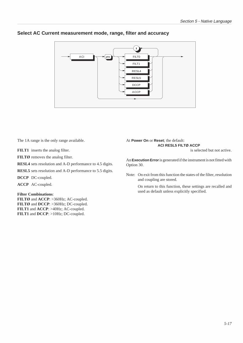
Section 5 - Native Language
5-17
Select AC Current measurement mode, range, filter and accuracy
The 1A range is the only range available.
FILT1 inserts the analog filter.
FILTØ removes the analog filter.
RESL4 sets resolution and A-D performance to 4.5 digits.
RESL5 sets resolution and A-D performance to 5.5 digits.
DCCP DC-coupled.
ACCP AC-coupled.
Filter Combinations:FILTØ and ACCP: >360Hz; AC-coupled.FILTØ and DCCP: >360Hz; DC-coupled.FILT1 and ACCP: >40Hz; AC-coupled.FILT1 and DCCP: >10Hz; DC-coupled.
At Power On or Reset ; the default:ACI RESL5 FILTØ ACCP
is selected but not active.
An Execution Error is generated if the instrument is not fitted withOption 30.
Note: On exit from this function the states of the filter, resolutionand coupling are stored.
On return to this function, these settings are recalled andused as default unless explicitly specified.
ACI
,FILT0
FILT1
RESL4
RESL5
DCCP
ACCP
phs

Section 5 - Native Language
5-18
Select Ohms measurement mode, range, filter and accuracy
Nrf is a decimal numeric value used to select the range.Thus for a modulus value of Nrf:
Ø to 199.9999 selects the 100Ω range.2ØØ to 1999.999 selects the 1kΩ range.2ØØØ to 19999.99 selects the 10kΩ range.2ØØØØ to 199999.9 selects the 100kΩ range2ØØØØØ to 1999999 selects the 1MΩ range>2ØØØØØØ selects the 10MΩ range.
Excessive digits in Nrf are rounded to 6.5 digits.
AUTO selects the autorange facility.When in AUTO, the DMM attempts to select the most appropriaterange, moving up-range on overload and down-range on less than18% of range. If there is still an overload on the 10MΩ range, thena measurement error will be generated.
A valid Nrf deselects the AUTO mode.
FILT1 inserts the analog filter.The NMRR is 74dB @ 50Hz/60Hz ±0.1%.
FILTØ removes the analog filter.The NMRR is 54dB @ 50Hz/60Hz ±0.1%.
RESL4 sets resolution and A-D performance to 4.5 digits.
RESL5 sets resolution and A-D performance to 5.5 digits.
RESL6 sets resolution and A-D performance to 6.5 digits.
WIRE2 - Two-wire input connection.
WIRE4 - Four-wire input connection.
At Power On or Reset ; the default:OHMS (10MΩ) RESL6 FILTØ WIRE4
is selected but not active.
Note: On exit from this function the states of the range, filterresolution and 2/4 wire connection are stored.
On return to this function, these settings are recalled andused as default unless explicitly specified.
2-Wire Measurements 4-wire Measurements
For the majority of applications thesimple 2-wire arrangement will beadequate. However, the valuedisplayed will include the resistanceof the connecting leads.
Use a twisted pair cable to reduceinduced voltages, particularly whereRx is high.
With a 4-wire connection the leadresistances have negligible effect and onlythe value of Rx is displayed.
OHMS
,Nrf
AUTO
FILT0
FILT1
RESL4
RESL5
RESL6
WIRE2
WIRE4
phs
Hi
Lo
I+
I-
Rx
(2-wireOhms)
(2-wireOhms)
Hi
Lo
I+
I-
Rx

Section 5 - Native Language
5-19
Select an input port and the ratio mode
All of the above selections are mutually exclusive.
OFF disconnects all inputs.
CH_A selects Channel A inputs (See Sect. 2 p2-3).
Option 40 Selections:
CH_B selects Channel B inputs (See Sect. 2 p2-3).
ADIVB takes readings from Channel A and Channel Binput alternately, then divides the Channel Areading by the Channel B reading to produce theresult.
ASUBB takes readings from Channel A and Channel Binput alternately, then subtracts the Channel Breading from the Channel A reading to producethe result.
DEVTN takes readings from both channels A and B. Theresulting deviation data obtained from this modeis of the form:
(A - B) / B
At Power On or Reset ; the default:INPUT OFF
is selected and active.
An Execution Error is generated if the instrument is notfitted with Option 40, together with an attempt being madeto select CH_B, ADIVB , ASUBB or DEVTN.
Select Local or Remote Guard
The above selections are mutually exclusive.
LCL Internal guard tracks and shields are internally connectedto Signal Common. The Guard pins of the front panelInput plug are open circuit.
REM Internal guard tracks and shields are disconnected fromSignal Common, and connected to the selected channel'sGuard pin on the front panel Analog Input plug (Ch A - pin7; Ch B - pin 9).
At Power On or Reset ; the default:GUARD LCL
is selected and active.
INPUT OFF
CH_A
CH_B
ADIVB
ASUBB
DEVTN
phs
GUARD LCL
REM
phs

Section 5 - Native Language
5-20
Perform Input ZeroThis command is used to remove the offsets at zero input. To ensure true zero input, the front panel input plug Hi and Lo pinsmust be shorted together. Channels A (Hi - pin 1; Low - pin 5) and B (option 40 only - Hi - pin 15; Low - pin 11) are zeroedseparately, and only the selected channel is zeroed.
The corrections are held in volatile memory, but are cleared only on power down.
Select Trigger Source
Response:Ø t No errors present.1 t Errors present.
Where: t = ; or <lf>
If any errors are present, the relevant error codes are placed in a queuewhich is accessible using the request DDQ?.(See *TST? on page 5-28.)
Note: ZERO? is not accepted in Autorange, or in any AC function. In thesecases an Execution Error is generated.
This command selects either the 'System' or an external trigger to initiate ameasurement.
If SYS is selected, then measurements can be taken using *TRG; X?; or the VXIword serial trigger command.
If EXT is selected, then measurements will be taken on receipt of suitablehardware triggers from the front panel BNC connector.
At Power On or Reset ; the default:TSRCE SYS
is selected and active.
ZERO?
TSRCE SYS
EXT
phs
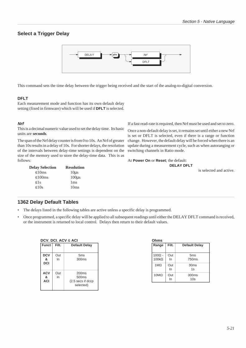
Section 5 - Native Language
5-21
This command sets the time delay between the trigger being received and the start of the analog-to-digital conversion.
If a fast read-rate is required, then Nrf must be used and set to zero.
Once a non-default delay is set, it remains set until either a new Nrfis set or DFLT is selected, even if there is a range or functionchange. However, the default delay will be forced when there is anupdate during a measurement cycle, such as when autoranging orswitching channels in Ratio mode.
At Power On or Reset ; the default:DELAY DFLT
is selected and active.
NrfThis is a decimal numeric value used to set the delay time. Its basicunits are seconds.
The span of the Nrf delay counter is from 0 to 10s. An Nrf of greaterthan 10s results in a delay of 10s. For shorter delays, the resolutionof the intervals between delay-time settings is dependent on thesize of the memory used to store the delay-time data. This is asfollows:
Delay Selection Resolution≤10ms 10µs≤100ms 100µs≤1s 1ms≤10s 10ms
Select a Trigger Delay
DFLTEach measurement mode and function has its own default delaysetting (fixed in firmware) which will be used if DFLT is selected.
1362 Delay Default Tables
• The delays listed in the following tables are active unless a specific delay is programmed.
• Once programmed, a specific delay will be applied to all subsequent readings until either the DELAY DFLT command is received,or the instrument is returned to local control. Delays then return to their default values.
DCV, DCI, ACV & ACIFunct Filt. Default Delay
DCV Out 5ms& In 300ms
DCI
ACV Out 200ms& In 500ms
ACI (2.5 secs if dccpselected)
OhmsRange Filt. Default Delay
100Ω - Out 5ms100kΩ In 750ms
1MΩ Out 30msIn 1s
10MΩ Out 300msIn 10s
DELAY Nrf
DFLT
phs

Section 5 - Native Language
5-22
Perform a System Trigger
Response for 4.5 digit resolution is an Nrf :
1 2 3 4 5 6 7 8 9 10 11 12s n x x x n n E s n n t
Response for 5.5 digit resolution is an Nrf :
1 2 3 4 5 6 7 8 9 10 11 12 13s n x x x n n n E s n n t
Response for 6.5 digit resolution is an Nrf :
1 2 3 4 5 6 7 8 9 10 11 12 13 14s n x x x n n n n E s n n t
Where:s = the sign: + or -.n = ASCII digit Ø to 9.x = either n or an ASCII decimal point.E = ASCII character identifying the exponent.t = ; or <lf> (= line feed).
Response for Overload: 2ØØ.ØØØE+33 t
The normal response is the most-recent measurement, which isread but not destroyed.
If a request is received while the DMM analog-to-digitalconversion is still in progress; then that conversion is allowed tocomplete, and its result is given as the response.
If RDG? is sent when no trigger has been received since PowerOn or Reset, the following response is generated:
-2Ø.ØØØØE+36 t
Where: t = ; or <lf>
An Execution Error is generated if an input channel is notconnected.
Fetch the Last Reading
TRG∗
RDG?
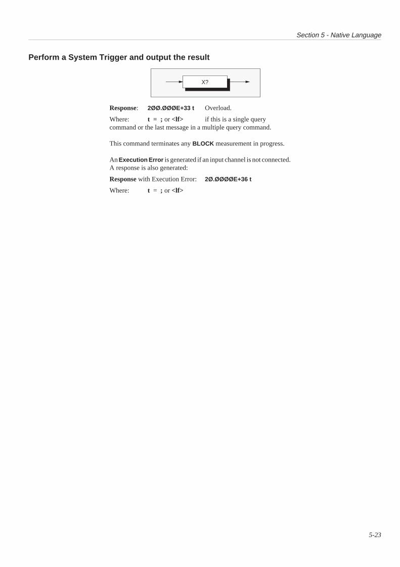
Section 5 - Native Language
5-23
Perform a System Trigger and output the result
Response: 2ØØ.ØØØE+33 t Overload.
Where: t = ; or <lf> if this is a single querycommand or the last message in a multiple query command.
This command terminates any BLOCK measurement in progress.
An Execution Error is generated if an input channel is not connected.A response is also generated:
Response with Execution Error: 2Ø.ØØØØE+36 t
Where: t = ; or <lf>
X?
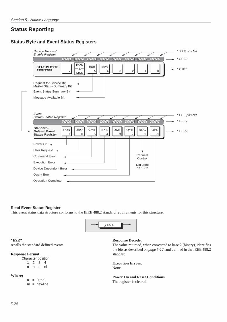
Section 5 - Native Language
5-24
Status Byte and Event Status Registers
Status Reporting
Read Event Status RegisterThis event status data structure conforms to the IEEE 488.2 standard requirements for this structure.
∗ESR?recalls the standard defined events.
Response Format:Character position
1 2 3 4n n n nl
Where:n = 0 to 9nl = newline
Response Decode:The value returned, when converted to base 2 (binary), identifiesthe bits as described on page 5-12, and defined in the IEEE 488.2standard.
Execution Errors:None
Power On and Reset ConditionsThe register is cleared.
0MSS
ESB MAVSTATUS BYTEREGISTER
Request for Service BitMaster Status Summary Bit
Event Status Summary Bit
Message Available Bit
AAAAAAAAAAAAAAAAAAAAAAAAA
Service RequestEnable Register
7 6 5 4 3 2 1 0PON URQ CME OPCEXE DDE QYE
Query Error
Power On
User Request
Command Error
Execution Error
Device Dependent Error
Operation Complete
Standard-Defined EventStatus Register
RQC
RequestControl
Not usedon 1362
AAAAAAAAAAAAAAAAAAAAAAAAA
EventStatus Enable Register
76
5 4 3 2 1
RQS
∗ SRE phs Nrf
∗ SRE?
∗ STB?
∗ ESE phs Nrf
∗ ESE?
∗ ESR?
ESR?*
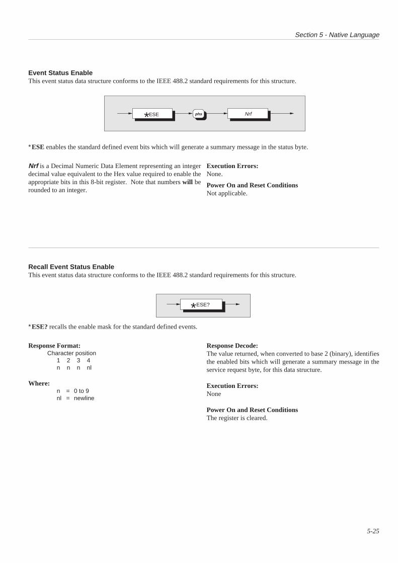
Section 5 - Native Language
5-25
Event Status EnableThis event status data structure conforms to the IEEE 488.2 standard requirements for this structure.
∗ESE enables the standard defined event bits which will generate a summary message in the status byte.
Response Format:Character position
1 2 3 4n n n nl
Where:n = 0 to 9nl = newline
∗ESE? recalls the enable mask for the standard defined events.
Recall Event Status EnableThis event status data structure conforms to the IEEE 488.2 standard requirements for this structure.
Response Decode:The value returned, when converted to base 2 (binary), identifiesthe enabled bits which will generate a summary message in theservice request byte, for this data structure.
Execution Errors:None
Power On and Reset ConditionsThe register is cleared.
Execution Errors:None.
Power On and Reset ConditionsNot applicable.
Nrf is a Decimal Numeric Data Element representing an integerdecimal value equivalent to the Hex value required to enable theappropriate bits in this 8-bit register. Note that numbers will berounded to an integer.
Nrfphs ESE*
ESE?*

Section 5 - Native Language
5-26
Service Request EnableThis measurement event status data structure conforms to the IEEE 488.2 standard requirements for this structure.
∗SRE enables the standard and user-defined summary bits in the service request byte, which willgenerate a service request.
Recall Service Request EnableThis measurement event status data structure conforms to the IEEE 488.2 standard requirements for this structure.
∗SRE?recalls the enable mask for the standard defined events.
Response Format:Character position
1 2 3 4n n n nl
Where:n = 0 to 9nl = newline
Response Decode:The value returned, when converted to base 2 (binary), identifiesthe enabled bits which will generate a service request.
Execution Errors:None.
Power On and Reset ConditionsNone.
Nrf is a Decimal Numeric Data Element representing an integerdecimal value equivalent to the Hex value required to enable theappropriate bits in this 8-bit register. Note that numbers will berounded to an integer.
Execution Errors:None.
Power On and Reset ConditionsNot applicable.
Nrfphs SRE*
SRE?*
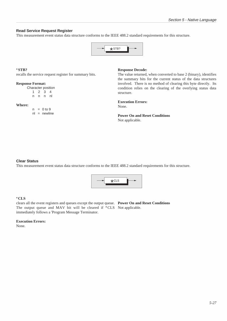
Section 5 - Native Language
5-27
Clear StatusThis measurement event status data structure conforms to the IEEE 488.2 standard requirements for this structure.
Read Service Request RegisterThis measurement event status data structure conforms to the IEEE 488.2 standard requirements for this structure.
∗STB?recalls the service request register for summary bits.
Response Format:Character position
1 2 3 4n n n nl
Where:n = 0 to 9nl = newline
Response Decode:The value returned, when converted to base 2 (binary), identifiesthe summary bits for the current status of the data structuresinvolved. There is no method of clearing this byte directly. Itscondition relies on the clearing of the overlying status datastructure.
Execution Errors:None.
Power On and Reset ConditionsNot applicable.
∗CLSclears all the event registers and queues except the output queue.The output queue and MAV bit will be cleared if ∗CLSimmediately follows a 'Program Message Terminator.
Execution Errors:None.
Power On and Reset ConditionsNot applicable.
STB?*
CLS*
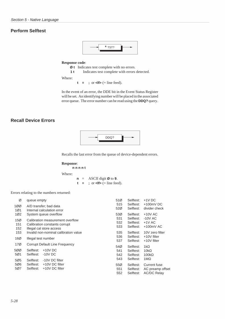
Section 5 - Native Language
5-28
Perform Selftest
Recall Device Errors
Response code:Ø t Indicates test complete with no errors.1 t Indicates test complete with errors detected.
Where:t = ; or <lf> (= line feed).
In the event of an error, the DDE bit in the Event Status Registerwill be set. An identifying number will be placed in the associatederror queue. The error number can be read using the DDQ? query.
Recalls the last error from the queue of device-dependent errors.
Response:n n n n t
Where:n = ASCII digit Ø to 9.t = ; or <lf> (= line feed).
Errors relating to the numbers returned:
Ø queue empty
1ØØ A/D transfer; bad data1Ø1 Internal calculation error1Ø2 System queue overflow
15Ø Calibration measurement overflow151 Calibration constants corrupt152 Illegal cal store access153 Invalid non-nominal calibration value
16Ø Illegal test number
17Ø Corrupt Default Line Frequency
5ØØ Selftest: +10V DC5Ø1 Selftest: -10V DC
5Ø5 Selftest: -10V DC filter5Ø6 Selftest: +10V DC filter5Ø7 Selftest: +10V DC filter
51Ø Selftest: +1V DC515 Selftest: +100mV DC52Ø Selftest: divider check
53Ø Selftest: +10V AC531 Selftest: -10V AC532 Selftest: +1V AC533 Selftest: +100mV AC
535 Selftest: 10V zero filter536 Selftest: +10V filter537 Selftest: +10V filter
54Ø Selftest: 1kΩ541 Selftest: 10kΩ542 Selftest: 100kΩ543 Selftest: 1MΩ
55Ø Selftest: Current fuse551 Selftest: AC preamp offset552 Selftest: AC/DC Relay
TST?∗
DDQ?
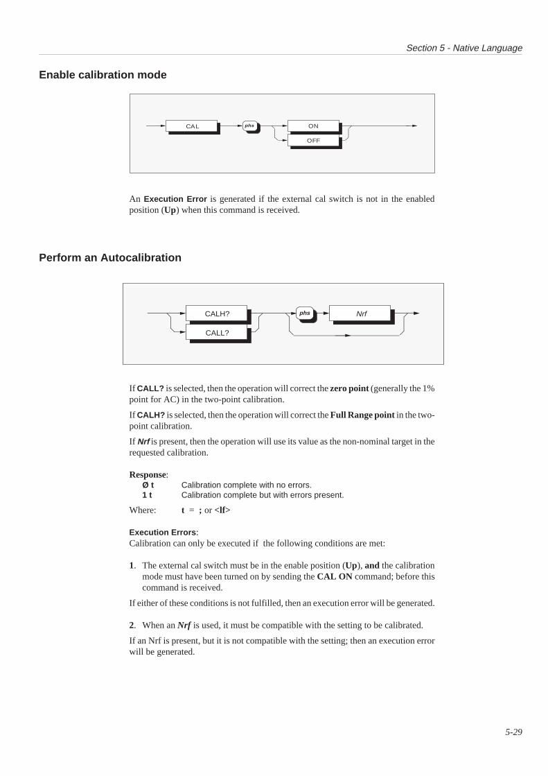
Section 5 - Native Language
5-29
Enable calibration mode
Perform an Autocalibration
If CALL? is selected, then the operation will correct the zero point (generally the 1%point for AC) in the two-point calibration.
If CALH? is selected, then the operation will correct the Full Range point in the two-point calibration.
If Nrf is present, then the operation will use its value as the non-nominal target in therequested calibration.
Response:Ø t Calibration complete with no errors.1 t Calibration complete but with errors present.
Where: t = ; or <lf>
Execution Errors :Calibration can only be executed if the following conditions are met:
1. The external cal switch must be in the enable position (Up), and the calibrationmode must have been turned on by sending the CAL ON command; before thiscommand is received.
If either of these conditions is not fulfilled, then an execution error will be generated.
2. When an Nrf is used, it must be compatible with the setting to be calibrated.
If an Nrf is present, but it is not compatible with the setting; then an execution errorwill be generated.
An Execution Error is generated if the external cal switch is not in the enabledposition (Up) when this command is received.
CAL ON
OFF
phs
CALH?
CALL?
Nrfphs
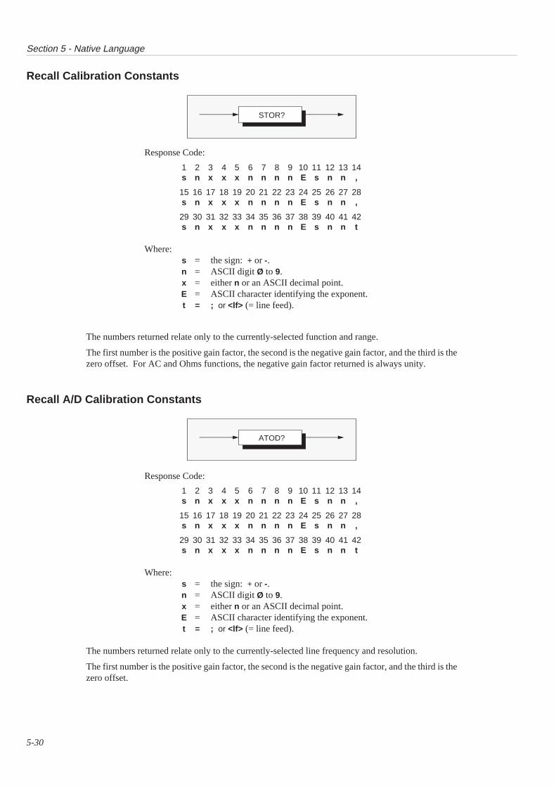
Section 5 - Native Language
5-30
Recall Calibration Constants
Recall A/D Calibration Constants
The numbers returned relate only to the currently-selected line frequency and resolution.
The first number is the positive gain factor, the second is the negative gain factor, and the third is thezero offset.
Response Code:
1 2 3 4 5 6 7 8 9 10 11 12 13 14s n x x x n n n n E s n n ,
15 16 17 18 19 20 21 22 23 24 25 26 27 28s n x x x n n n n E s n n ,
29 30 31 32 33 34 35 36 37 38 39 40 41 42s n x x x n n n n E s n n t
Where:s = the sign: + or -.n = ASCII digit Ø to 9.x = either n or an ASCII decimal point.E = ASCII character identifying the exponent.t = ; or <lf> (= line feed).
The numbers returned relate only to the currently-selected function and range.
The first number is the positive gain factor, the second is the negative gain factor, and the third is thezero offset. For AC and Ohms functions, the negative gain factor returned is always unity.
Response Code:
1 2 3 4 5 6 7 8 9 10 11 12 13 14s n x x x n n n n E s n n ,
15 16 17 18 19 20 21 22 23 24 25 26 27 28s n x x x n n n n E s n n ,
29 30 31 32 33 34 35 36 37 38 39 40 41 42s n x x x n n n n E s n n t
Where:s = the sign: + or -.n = ASCII digit Ø to 9.x = either n or an ASCII decimal point.E = ASCII character identifying the exponent.t = ; or <lf> (= line feed).
STOR?
ATOD?

Section 5 - Native Language
5-31
Recall Calibration Values Stored during Calibration Sequence
Response Format
Response DetailA calibration trigger (see CALH? and CALL? earlier) can initiateseveral 'Calibration Operations', depending on the type ofcalibration being performed.
Each Calibration Operation takes four readings. It then computestheir mean, which ultimately results in a correction constant(sometimes directly, and sometimes by computation with themeans of other operations).
Thus a group of five values (four readings and their mean) resultsfrom every operation. Each group is placed into the calibrationbuffer and all five values can be recalled by a single CVAL? query.
They are returned as five pairs of numbers, the first four pairsrepresenting the reading values and the fifth pair representing theirmean; all from a single calibration operation. In each pair, the firstnumber is the value itelf (Nr3 format) and the second is its indexnumber (Nr1 format) in the calibration buffer.
The calibration buffer has sufficient capacity for the greatestnumber of operations to result from a single calibration trigger.
CVAL? returns the values from the calibration buffer, starting atthe highest occupied buffer location, decrementing the indexnumber as it reads each value. When the index reaches Ø, all thevalues have been read. Any subsequent CVAL? continues toreturn both the value at index Ø and the index No Ø, until anothercalibration trigger is commanded.
The next calibration trigger will place new values in the buffer asthe calibration operations proceed, starting again at register Ø.
CVAL?
Nr1Nr3 ,
,
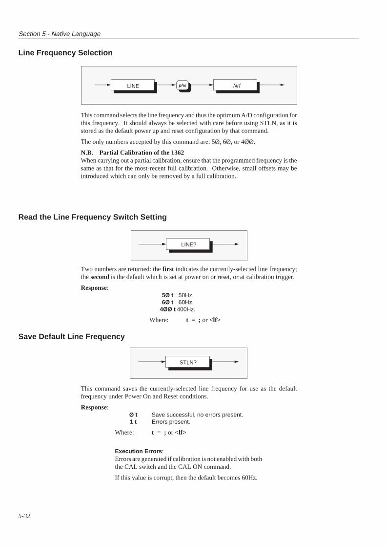
Section 5 - Native Language
5-32
Line Frequency Selection
Read the Line Frequency Switch Setting
Save Default Line Frequency
This command selects the line frequency and thus the optimum A/D configuration forthis frequency. It should always be selected with care before using STLN, as it isstored as the default power up and reset configuration by that command.
The only numbers accepted by this command are: 5Ø, 6Ø, or 4ØØ.
N.B. Partial Calibration of the 1362When carrying out a partial calibration, ensure that the programmed frequency is thesame as that for the most-recent full calibration. Otherwise, small offsets may beintroduced which can only be removed by a full calibration.
Two numbers are returned: the first indicates the currently-selected line frequency;the second is the default which is set at power on or reset, or at calibration trigger.
Response:5Ø t 50Hz.6Ø t 60Hz.
4ØØ t 400Hz.
Where: t = ; or <lf>
This command saves the currently-selected line frequency for use as the defaultfrequency under Power On and Reset conditions.
Response:Ø t Save successful, no errors present.1 t Errors present.
Where: t = ; or <lf>
Execution Errors :Errors are generated if calibration is not enabled with boththe CAL switch and the CAL ON command.
If this value is corrupt, then the default becomes 60Hz.
NrfphsLINE
LINE?
STLN?
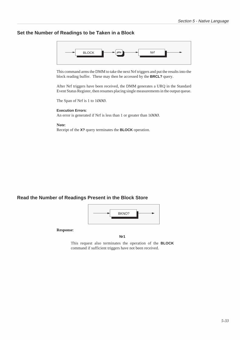
Section 5 - Native Language
5-33
Set the Number of Readings to be Taken in a Block
Read the Number of Readings Present in the Block Store
This command arms the DMM to take the next Nrf triggers and put the results into theblock reading buffer. These may then be accessed by the BRCL? query.
After Nrf triggers have been received, the DMM generates a URQ in the StandardEvent Status Register, then resumes placing single measurements in the output queue.
The Span of Nrf is 1 to 1ØØØ.
Execution Errors :An error is generated if Nrf is less than 1 or greater than 1ØØØ.
Note:Receipt of the X? query terminates the BLOCK operation.
Response:
Nr1
This request also terminates the operation of the BLOCKcommand if sufficient triggers have not been received.
BLOCK Nrf phs
BKNO?
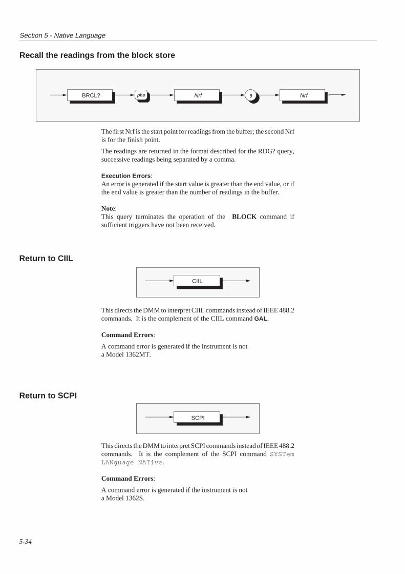
Section 5 - Native Language
5-34
Recall the readings from the block store
Return to CIIL
Return to SCPI
The first Nrf is the start point for readings from the buffer; the second Nrfis for the finish point.
The readings are returned in the format described for the RDG? query,successive readings being separated by a comma.
Execution Errors :An error is generated if the start value is greater than the end value, or ifthe end value is greater than the number of readings in the buffer.
Note:This query terminates the operation of the BLOCK command ifsufficient triggers have not been received.
This directs the DMM to interpret CIIL commands instead of IEEE 488.2commands. It is the complement of the CIIL command GAL .
Command Errors:
A command error is generated if the instrument is nota Model 1362MT.
This directs the DMM to interpret SCPI commands instead of IEEE 488.2commands. It is the complement of the SCPI command SYSTemLANguage NATive .
Command Errors:
A command error is generated if the instrument is nota Model 1362S.
BRCL? ,Nrf Nrfphs
CIIL
SCPI

Section 5 - Native Language
5-35
Diagnostic Commands
Perform an Individual Test from the Selftest List
The Nrf for this command gives the test number to be performed. Thetest will leave the DMM in the hardware configuration required for thetest.
Note that the individual test numbers used in this command are the sameas the numbers of the failed test that are reported by the DDQ? query. Forgroup test add 100 to the test number.
Response Code
The Nr1 in this response is eitherØ for test passor 1 for test fail
The first Nr3 is the value measured by the DMM during the test.The second Nr3 is the absolute high limit of the test.The third Nr3 is the absolute low limit of the test.
TEST? Nrf phs
Nr1 , Nr3Nr3 ,Nr3 ,
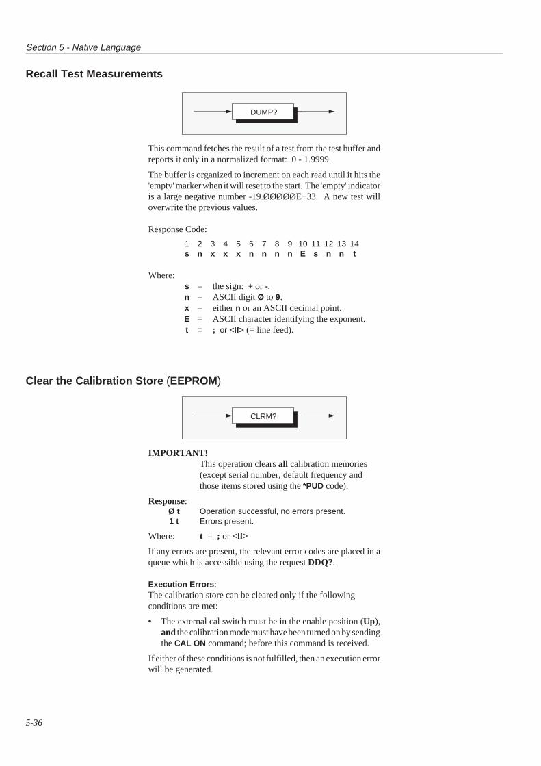
Section 5 - Native Language
5-36
Recall Test Measurements
This command fetches the result of a test from the test buffer andreports it only in a normalized format: 0 - 1.9999.
The buffer is organized to increment on each read until it hits the'empty' marker when it will reset to the start. The 'empty' indicatoris a large negative number -19.ØØØØØE+33. A new test willoverwrite the previous values.
Response Code:
1 2 3 4 5 6 7 8 9 10 11 12 13 14s n x x x n n n n E s n n t
Where:s = the sign: + or -.n = ASCII digit Ø to 9.x = either n or an ASCII decimal point.E = ASCII character identifying the exponent.t = ; or <lf> (= line feed).
Clear the Calibration Store (EEPROM)
IMPORTANT!This operation clears all calibration memories(except serial number, default frequency andthose items stored using the *PUD code).
Response:Ø t Operation successful, no errors present.1 t Errors present.
Where: t = ; or <lf>
If any errors are present, the relevant error codes are placed in aqueue which is accessible using the request DDQ?.
Execution Errors :The calibration store can be cleared only if the followingconditions are met:
• The external cal switch must be in the enable position (Up),and the calibration mode must have been turned on by sendingthe CAL ON command; before this command is received.
If either of these conditions is not fulfilled, then an execution errorwill be generated.
DUMP?
CLRM?
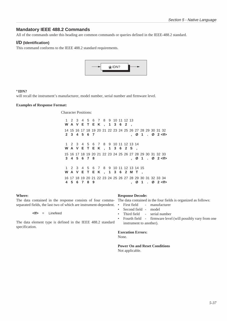
Section 5 - Native Language
5-37
Mandatory IEEE 488.2 Commands
I/D (Identification)This command conforms to the IEEE 488.2 standard requirements.
∗IDN?will recall the instrument’s manufacturer, model number, serial number and firmware level.
Examples of Response Format:
All of the commands under this heading are common commands or queries defined in the IEEE-488.2 standard.
Character Positions:
1 2 3 4 5 6 7 8 9 10 11 12 13W A V E T E K , 1 3 6 2 ,
14 15 16 17 18 19 20 21 22 23 24 25 26 27 28 29 30 31 322 3 4 5 6 7 , Ø 1 . Ø 2 <lf>
1 2 3 4 5 6 7 8 9 10 11 12 13 14W A V E T E K , 1 3 6 2 S ,
15 16 17 18 19 20 21 22 23 24 25 26 27 28 29 30 31 32 333 4 5 6 7 8 , Ø 1 . Ø 2 <lf>
1 2 3 4 5 6 7 8 9 10 11 12 13 14 15W A V E T E K , 1 3 6 2 M T ,
16 17 18 19 20 21 22 23 24 25 26 27 28 29 30 31 32 33 344 5 6 7 8 9 , Ø 1 . Ø 2 <lf>
Where:The data contained in the response consists of four comma-separated fields, the last two of which are instrument-dependent.
<lf> = Linefeed
The data element type is defined in the IEEE 488.2 standardspecification.
Response Decode:The data contained in the four fields is organized as follows:• First field - manufacturer• Second field - model• Third field - serial number• Fourth field - firmware level (will possibly vary from one
instrument to another).
Execution Errors:None.
Power On and Reset ConditionsNot applicable.
IDN?*
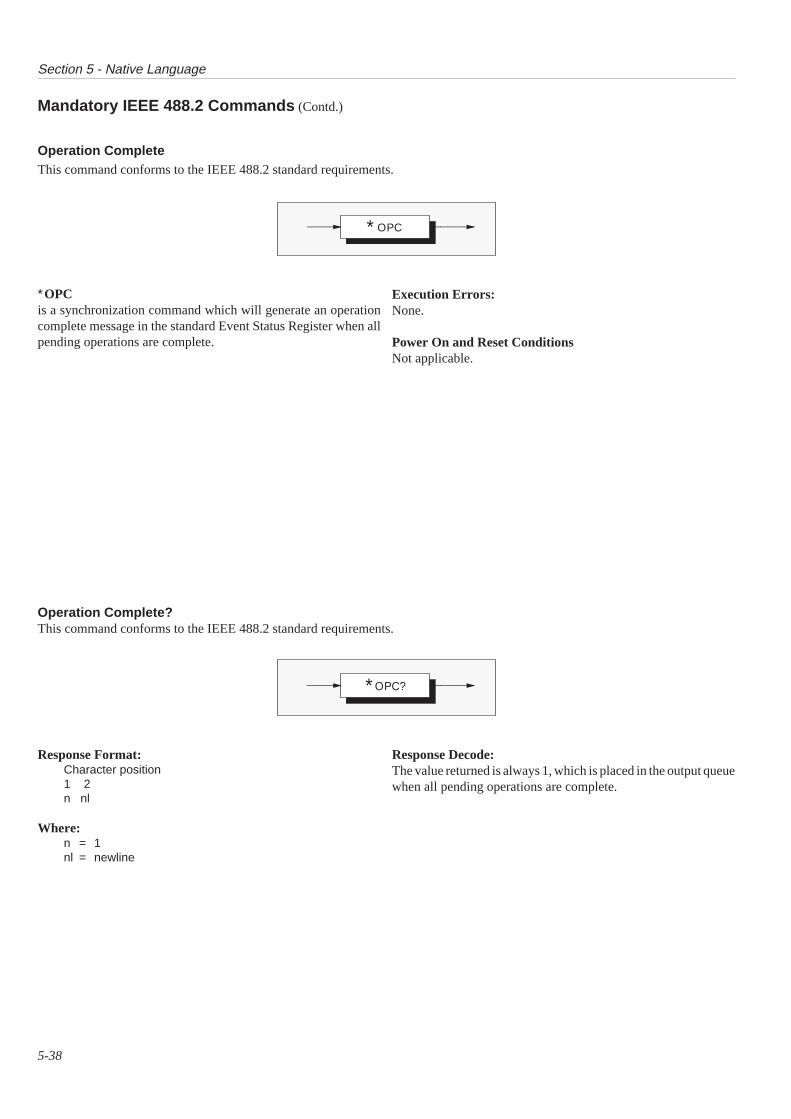
Section 5 - Native Language
5-38
Mandatory IEEE 488.2 Commands (Contd.)
Operation CompleteThis command conforms to the IEEE 488.2 standard requirements.
Response Format:Character position1 2n nl
Where:n = 1nl = newline
Response Decode:The value returned is always 1, which is placed in the output queuewhen all pending operations are complete.
Operation Complete?This command conforms to the IEEE 488.2 standard requirements.
∗OPCis a synchronization command which will generate an operationcomplete message in the standard Event Status Register when allpending operations are complete.
Execution Errors:None.
Power On and Reset ConditionsNot applicable.
OPC∗
OPC?∗

Section 5 - Native Language
5-39
ResetThis command conforms to the IEEE 488.2 standard requirements.
WaitThis command conforms to the IEEE 488.2 standard requirements.
Execution Errors:None.
Power On and Reset ConditionsNot applicable.
∗RSTwill reset the instrument to a defined condition, detailed inAppendix B to this section.
The reset condition is independent of past-use history of theinstrument except as noted below:
∗RST does not affect the following:
• the selected address of the instrument;• calibration data that affect specifications;• SRQ mask conditions;• the state of the IEEE 488 interface;• stored math constants.
∗WAIprevents the instrument from executing any further commands orqueries until the No Pending Operations Flag is set true. This isa mandatory command for IEEE-488.2 but has no relevance to thisinstrument as there are no parallel processes requiring PendingOperation Flags.
Execution Errors:None.
Power On and Reset ConditionsNot applicable.
RST∗
WAI∗
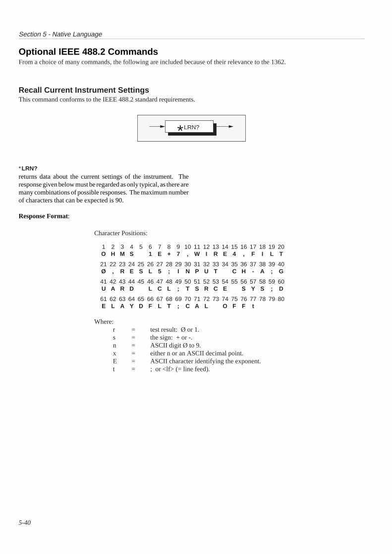
Section 5 - Native Language
5-40
Optional IEEE 488.2 CommandsFrom a choice of many commands, the following are included because of their relevance to the 1362.
∗LRN?returns data about the current settings of the instrument. Theresponse given below must be regarded as only typical, as there aremany combinations of possible responses. The maximum numberof characters that can be expected is 90.
Response Format:
Character Positions:
1 2 3 4 5 6 7 8 9 10 11 12 13 14 15 16 17 18 19 20O H M S 1 E + 7 , W I R E 4 , F I L T
21 22 23 24 25 26 27 28 29 30 31 32 33 34 35 36 37 38 39 40Ø , R E S L 5 ; I N P U T C H - A ; G
41 42 43 44 45 46 47 48 49 50 51 52 53 54 55 56 57 58 59 60U A R D L C L ; T S R C E S Y S ; D
61 62 63 64 65 66 67 68 69 70 71 72 73 74 75 76 77 78 79 80E L A Y D F L T ; C A L O F F t
Where:r = test result: Ø or 1.s = the sign: + or -.n = ASCII digit Ø to 9.x = either n or an ASCII decimal point.E = ASCII character identifying the exponent.t = ; or <lf> (= line feed).
Recall Current Instrument SettingsThis command conforms to the IEEE 488.2 standard requirements.
LRN?*
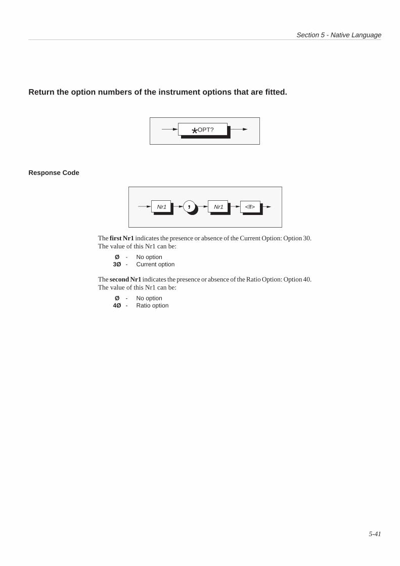
Section 5 - Native Language
5-41
Response Code
Return the option numbers of the instrument options that are fitted.
The first Nr1 indicates the presence or absence of the Current Option: Option 30.The value of this Nr1 can be:
Ø - No option3Ø - Current option
The second Nr1 indicates the presence or absence of the Ratio Option: Option 40.The value of this Nr1 can be:
Ø - No option4Ø - Ratio option
OPT?*
<lf>Nr1Nr1 ,
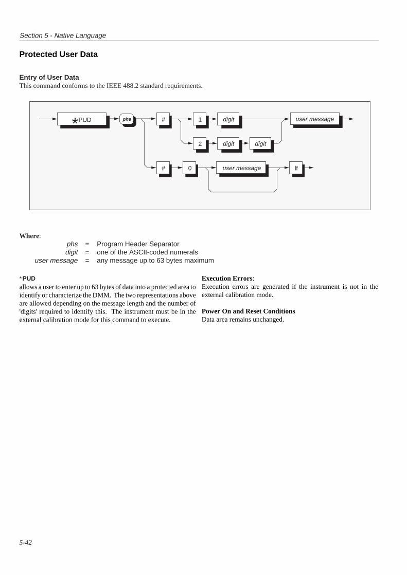
Section 5 - Native Language
5-42
Entry of User DataThis command conforms to the IEEE 488.2 standard requirements.
Protected User Data
Where:phs = Program Header Separatordigit = one of the ASCII-coded numerals
user message = any message up to 63 bytes maximum
∗PUDallows a user to enter up to 63 bytes of data into a protected area toidentify or characterize the DMM. The two representations aboveare allowed depending on the message length and the number of'digits' required to identify this. The instrument must be in theexternal calibration mode for this command to execute.
Execution Errors:Execution errors are generated if the instrument is not in theexternal calibration mode.
Power On and Reset ConditionsData area remains unchanged.
PUD* #
# 0
1
2
digit user message
user message
digit digit
lf
phs
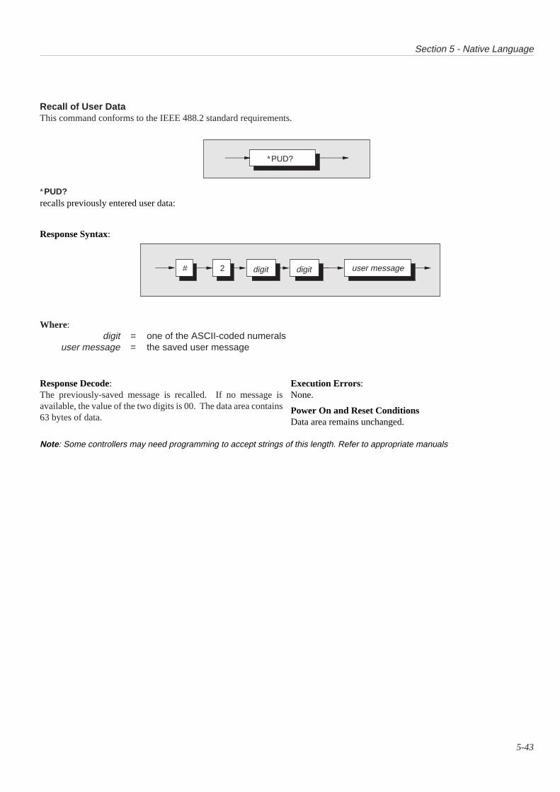
Section 5 - Native Language
5-43
Recall of User DataThis command conforms to the IEEE 488.2 standard requirements.
∗PUD?recalls previously entered user data:
Response Syntax:
Response Decode:The previously-saved message is recalled. If no message isavailable, the value of the two digits is 00. The data area contains63 bytes of data.
Execution Errors:None.
Power On and Reset ConditionsData area remains unchanged.
Note : Some controllers may need programming to accept strings of this length. Refer to appropriate manuals
Where:digit = one of the ASCII-coded numerals
user message = the saved user message
∗PUD?
# 2 user messagedigit digit

this page deliberately left blank

APPENDIX A to SECTION 51362 Device Settings at Power On
5-A1
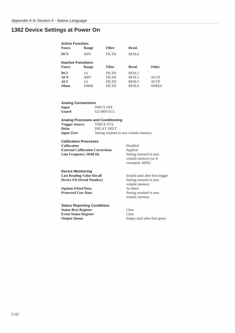
Appendix A to Section 5 - Native Language
5-A2
1362 Device Settings at Power On
Active Function:Funct. Range Filter Resol.
DCV 300V FILTØ RESL6
Inactive Functions:Funct. Range Filter Resol. Other
DCI 1A FILTØ RESL5ACV 300V FILTØ RESL5 ACCPACI 1A FILTØ RESL5 ACCPOhms 10MΩ FILTØ RESL6 WIRE4
Analog ConnectionsInput INPUT OFFGuard GUARD LCL
Analog Processes and ConditioningTrigger Source TSRCE SYSDelay DELAY DFLTInput Zero Setting retained in non-volatile memory
Calibration ProcessesCalibration DisabledExternal Calibration Corrections AppliedLine Frequency 50/60 Hz Setting retained in non-
volatile memory (or ifcorrupted, 60Hz)
Device MonitoringLast Reading Value Recall Invalid until after first triggerDevice I/D (Serial Number) Setting retained in non-
volatile memoryOptions Fitted Data As fittedProtected User Data Setting retained in non-
volatile memory
Status Reporting ConditionsStatus Byte Register ClearEvent Status Register ClearOutput Queue Empty until after first query

SECTION 6GUIDE to CIIL COMMAND LANGUAGE
6-1

Section 6 - MATE CIIL Language
6-2
SECTION 6 Guide to CIIL Command Language
Control Interface Intermediate Language (CIIL)
The instrument will communicate in accordance with the MATE Specification Document Standard 2806763 Revision C, 21 Jun 1988.
All references to CIIL in this Section are with respect to 2806763 Rev C, 21 Jun 1988.
Command Code SummaryThe minimum op-code requirements for a sensor unit (the DMM) are :
FNC SET SRX INX FTH CLS OPN RST CNF IST STAand the optional GAL
The only accepted <noun>s for this instrument are:
DCS ACS IMP
The only valid <mode-des> for this instrument are:
ACCP VOLT VRMS RESI CURR
The only used <noun-mod>s are
ACCF ACCP ACPL CURR DCPL FORW FREQ GARDGAWD MAXT RESI TWOW TSRC VOLT VRMS
‘Power On’ Default Settings
If it is not possible to set the DMM into its initial state (due to ahardware fault, for example) then the DMM will generate a FatalError and attempt to report the failure at the first opportunity. TheDMM will not respond to any further commands once the fatalerror has been reported.
When the DMM has finished its initialization, it is then ready toaccept commands.
After the power has been applied, the DMM will perform itspower-on configuration routine. This routine will set the DMManalogue circuits into their initial states:
DC300V RangeInput DisconnectedNo FilterLocal GuardNo Autorange6.5 Digit

Section 6 - MATE CIIL Language
6-3
Syntax Diagram
Note 1: The CURR <mchar> is only valid if the DMM has current fitted.
Note 2: The channel :CH1 is only valid if the DMM has ratio fitted.
Note 3: In the case of DCS, ACCP causes the AC measurement mode to be selected, enabling the DMM to measure the ACcomponent of a DC signal.
Note 4: All DCS measurements will be in 6.5 digit resolution.
All ACS measurements will be in 5.5 digit resolution.
All IMP measurements will be in 6.5 digit resolution.
All DCS CURR measurements will be in 6.5 digit resolution.
All ACS CURR measurements will be in 5.5 digit resolution.
N.B. All fields within a terminated string must be separated by an ASCII space.
FNC <noun> <mchar> <port>
This op-code is used to set the measurement configuration of the DMM. The FNC op-mode must always be at the start of a commandstring and may or may not be followed by the SET, SRN or SRX op-code(s).
The <noun> is used to select a specific measurement quantity, ie DCS for DC signals, IMP for resistance (impedance) and ACS for ACsignals.
The <mchar>s that may be applied to the <noun>s are shown in the syntax diagram below.
FNC DCS VOLT
ACCP
CURR
RESI
VOLT
VRMS
CURR
IMP
ACS
:CHØ
:CH1

Section 6 - MATE CIIL Language
6-4
Syntax Diagram
Control Interface Intermediate Language (CIIL) (Contd.)
N.B. All fields within a terminated string must be separated by an ASCII space.
SET, SRN and SRX Associated with DCS
Note 1: The <mchar> must match the <mchar> in the FNC command, i.e. either VOLT, ACCP or CURR.
Note 2: If the DMM can measure current, then the ACCP <mchar> is modified to include an optional <unit> field, e.g. in thesyntax diagram below:
The <unit> :A allows the measurement of the AC component of a current signal.
Syntax DiagramN.B. All fields within a terminated string must be separated by an ASCII space.
SET <mchar> <value>
<value>
<value>
<value>
<value>
INT
FREQ
GAWD
<crlf>
AUTO
ACCFSRX
SRN
SET
MAXT
TSRC
EXT
GARD
SET ACCP <value>
AUTO
SRX
SRN
:A <crlf>

Section 6 - MATE CIIL Language
6-5
Note 3: If SET GARD is present, then the DMM selects REMOTE GUARD.
If SET GARD is not present the default of LOCAL GUARD is selected.
Note 4: SET TSRC EXT allows measurement trigggers to come from the BNC connector on the front panel.
Note 5: The <value> following the <mchar> selects the range of the DMM according to the table :
Note 6: If AUTO follows the <mchar> instead of a <value>, then the DMM goes into the autorange mode and will select themost appropriate measurement range within its capabilities.
Note 7: The <noun-mod>s ACCF, FREQ and GAWD are all used to select the analogue filter in the DMM.
In the case of ACCF and FREQ:
If <value> > 40 (Hz) then the filter is de-selected.
If <value> ≤ 40 (Hz) or less then the filter is selected.
In the case of GAWD:
If <value> > 0.025 the filter is selected
If <value> ≤ 0.025 then the filter is de-selected.
Note that only positive <value>s are allowed. Negative <values>s will give an error.
Note 8: MAXT is used to select an external trigger window.
The <value> that follows the MAXT <noun-mod> must be greater than zero and less than 10 Seconds.
This <value> will then be used in checking the time between the trigger command and the external trigger actuallyarriving. If the external trigger does not arrive within the specified time, a timeout condition will occur and will bereported at the first opportunity.
Note 9: SET, SRN and SRX commands may only follow on from a FNC command. They may not be used as an independentcommand string.
Absolute <value> DMM Range
<value> < Ø.2 100mVØ.2 ≤ <value> < 2.Ø 1V2.Ø ≤ <value> < 2Ø.Ø 10V
2Ø.Ø ≤ <value> < 2ØØ.Ø 100V2ØØ.Ø ≤ <value> 300V
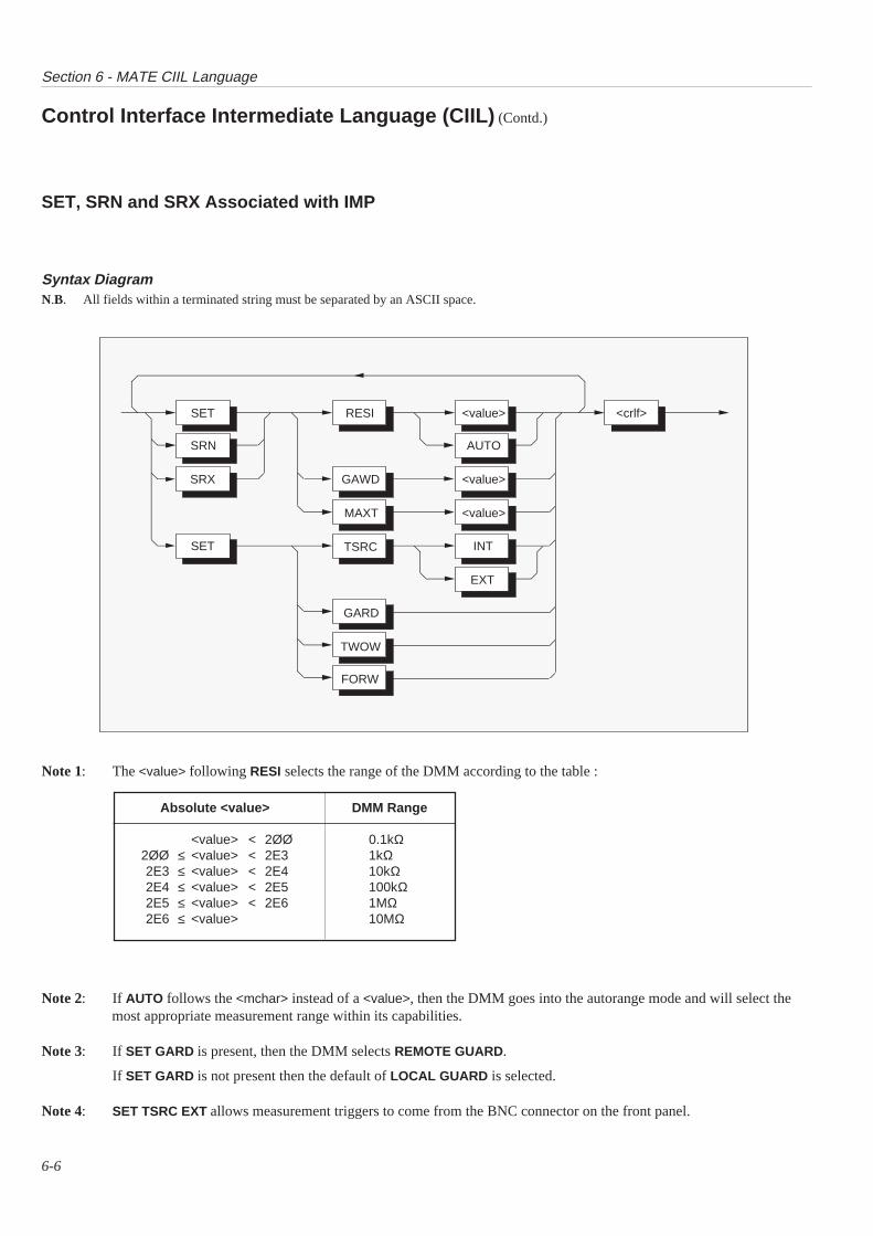
Section 6 - MATE CIIL Language
6-6
Syntax Diagram
Note 1: The <value> following RESI selects the range of the DMM according to the table :
Absolute <value> DMM Range
<value> < 2ØØ 0.1kΩ2ØØ ≤ <value> < 2E3 1kΩ2E3 ≤ <value> < 2E4 10kΩ2E4 ≤ <value> < 2E5 100kΩ2E5 ≤ <value> < 2E6 1MΩ2E6 ≤ <value> 10MΩ
Note 2: If AUTO follows the <mchar> instead of a <value>, then the DMM goes into the autorange mode and will select themost appropriate measurement range within its capabilities.
Note 3: If SET GARD is present, then the DMM selects REMOTE GUARD.
If SET GARD is not present then the default of LOCAL GUARD is selected.
Note 4: SET TSRC EXT allows measurement triggers to come from the BNC connector on the front panel.
Control Interface Intermediate Language (CIIL) (Contd.)
N.B. All fields within a terminated string must be separated by an ASCII space.
SET, SRN and SRX Associated with IMP
SET RESI <value>
<value>
<value>MAXT
<crlf>
AUTO
GAWDSRX
SRN
INTSET TSRC
EXT
GARD
TWOW
FORW
Section 6 - MATE CIIL Language
6-7
Note 5: SET TWOW selects the two wire method for measuring Ohms.
SET FORW selects the four wire method for measuring Ohms.
The default is SET TWOW if neither is specified.
Note 6: The <noun-mod> GAWD is used to select the analogue filter in the DMM.
If the <value> > 0.025 the filter is selected
If the <value> ≤ 0.025 then the filter is de-selected.
Note that only positive <value>s are allowed. Negative <values>s will give an error.
Note 7: MAXT is used to select an external trigger window.
The <value> that follows the MAXT <noun-mod> must be greater than zero and less than 10 Seconds.
This <value> will then be used in checking the time between the trigger command and the external trigger actuallyarriving. If the external trigger does not arrive within the specified time, a timeout condition will occur and will bereported at the first opportunity.
Note 8: SET, SRN and SRX commands may only follow on from an FNC command. They may not be used as an independentcommand string.
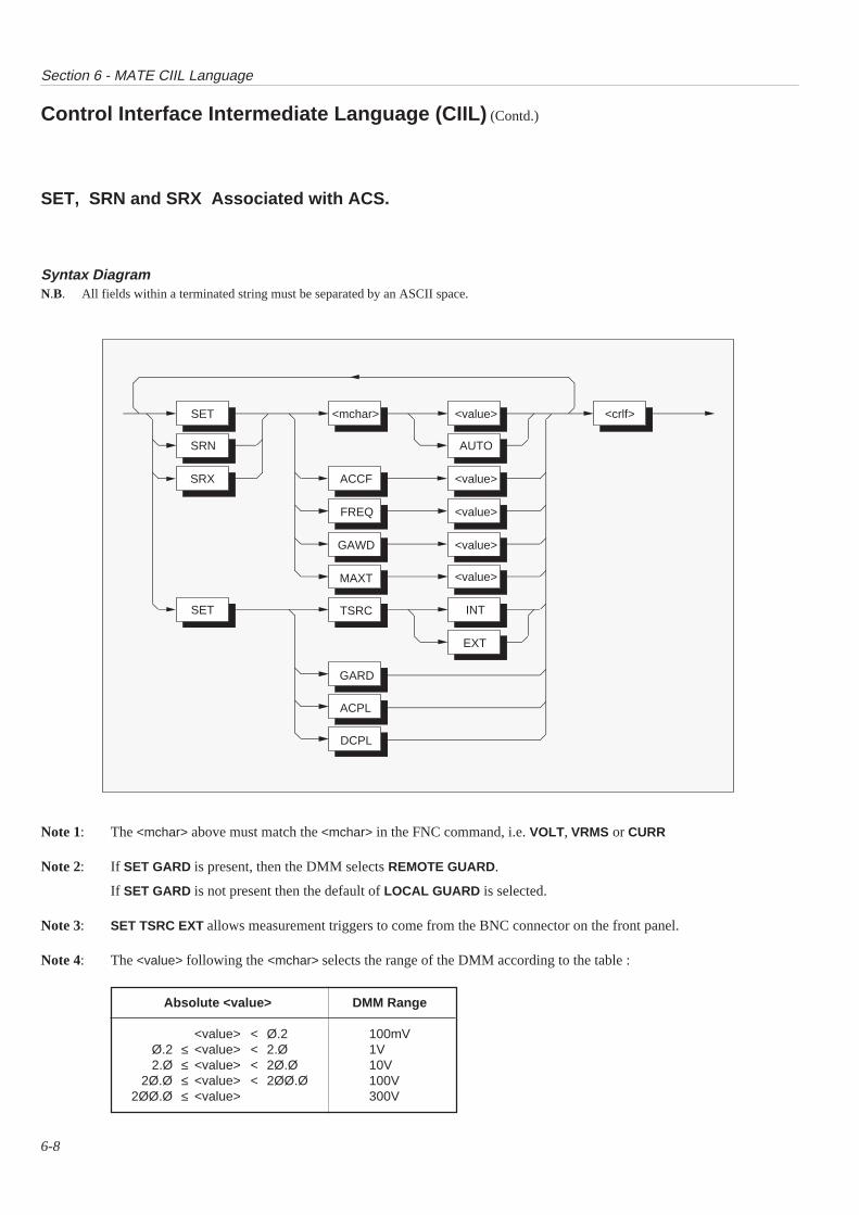
Section 6 - MATE CIIL Language
6-8
Syntax Diagram
Absolute <value> DMM Range
<value> < Ø.2 100mVØ.2 ≤ <value> < 2.Ø 1V2.Ø ≤ <value> < 2Ø.Ø 10V
2Ø.Ø ≤ <value> < 2ØØ.Ø 100V2ØØ.Ø ≤ <value> 300V
Note 1: The <mchar> above must match the <mchar> in the FNC command, i.e. VOLT, VRMS or CURR
Note 2: If SET GARD is present, then the DMM selects REMOTE GUARD.
If SET GARD is not present then the default of LOCAL GUARD is selected.
Note 3: SET TSRC EXT allows measurement triggers to come from the BNC connector on the front panel.
Note 4: The <value> following the <mchar> selects the range of the DMM according to the table :
Control Interface Intermediate Language (CIIL) (Contd.)
N.B. All fields within a terminated string must be separated by an ASCII space.
SET, SRN and SRX Associated with ACS.
SET <mchar> <value>
<value>
<value>
<value>
<value>
INT
FREQ
GAWD
<crlf>
AUTO
ACCFSRX
SRN
SET
MAXT
TSRC
EXT
GARD
ACPL
DCPL
Section 6 - MATE CIIL Language
6-9
Note 5: If AUTO follows the <mchar> instead of a <value>, then the DMM goes into the autorange mode and will select themost appropriate measurement range within its capabilities.
Note 6: SET ACPL selects measurement of the AC component of the signal
SET DCPL selects measurement of the sum of the AC and DC components of the signal.
Note 7: The <noun-mod>s ACCF, FREQ and GAWD are all used to select the analogue filter in the DMM.
In the case of ACCF and FREQ:
If <value> > 40 (Hz) then the filter is de-selected.
If <value> ≤ 40 (Hz) or less then the filter is selected.
In the case of GAWD:
If <value> > 0.025 the filter is selected
If <value> ≤ 0.025 then the filter is de-selected.
Note that only positive <value>s are allowed. Negative <value>s will give an error.
Note 8: MAXT is used to select an external trigger window.
The <value> that follows the MAXT <noun-mod> must be greater than zero and less than 10 Seconds.
This <value> will then be used in checking the time between the trigger command and the external trigger actuallyarriving. If the external trigger does not arrive within the specified time, a timeout condition will occur and will bereported at the first opportunity.
Note 9: SET, SRN and SRX commands may only follow on from an FNC command. They may not be used as an independentcommand string.
Section 6 - MATE CIIL Language
6-10
Control Interface Intermediate Language (CIIL) (Contd.)
INX <mchar><crlf>
This op-code is used to trigger the DMM in TSRC INT mode, or arm the DMM for an external trigger if in TSRC EXT mode. Note thatthe <mchar> must match the one sent in the FNC command.
This command replies in accordance with Section 5.3.2.1.1. e.g: <sp><ascii-int><crlf>
Where the ascii-int is a value representing the timeout required before the next FTH is sent to the DMM.
FTH <mchar><crlf>
This op-code is used to retrieve data from the DMM. Its main use is in connection with a previous trigger command INX.
The <mchar> in the FTH op-code must match the <mchar> received in the last FNC op-code. Under normal conditions, where themeasurement has successfully been taken, this command will cause the DMM to return:
<space><value><crlf>
In the event of a previous (unreported) error the DMM will return a suitable error string of the form described in Rev C; Section 5.3.4onwards.
CLS :CH0 <crlf> ; OPN :CH0 <crlf>
CLS :CH1 <crlf> ; OPN :CH1 <crlf>(These two only valid if Ratio fitted)
These op-codes are used to connect and disconnect the DMM to the measurement bus.
In the disconnected mode (OPN), there is total isolation between all measurement terminals (Hi , Lo, I+ , I- and Guard) of the DMMand the measurement bus.
Note that it is invalid to attempt to trigger a measurement (using INX) when the DMM is disconnected (OPN). If this is attempted thenan error will be reported at the first opportunity.
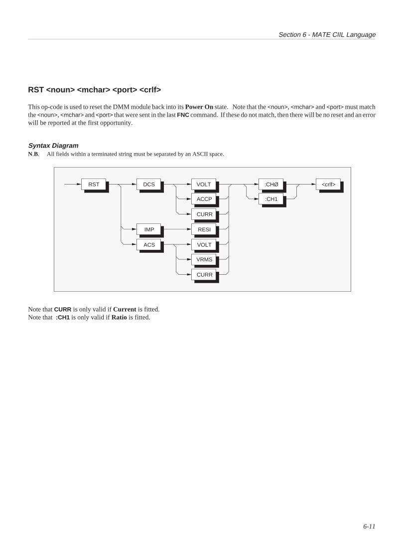
Section 6 - MATE CIIL Language
6-11
RST <noun> <mchar> <port> <crlf>
This op-code is used to reset the DMM module back into its Power On state. Note that the <noun>, <mchar> and <port> must matchthe <noun>, <mchar> and <port> that were sent in the last FNC command. If these do not match, then there will be no reset and an errorwill be reported at the first opportunity.
Syntax Diagram
Note that CURR is only valid if Current is fitted.Note that :CH1 is only valid if Ratio is fitted.
N.B. All fields within a terminated string must be separated by an ASCII space.
RST DCS VOLT
ACCP
CURR
RESI
VOLT
VRMS
CURR
IMP
ACS
:CHØ
:CH1
<crlf>
Section 6 - MATE CIIL Language
6-12
Control Interface Intermediate Language (CIIL) (Contd.)
CNF<crlf> ; IST<crlf>
These two op-codes both cause the DMM to perform the Internal Selftest routine. Note that neither command has any modifiers.
In the case of a selftest PASS, the message that is returned on receipt of the next STA command is:
<space><crlf>
In the case of a selftest FAIL the message is:
F07DMM01 (DEV): <ascii string><crlf>
Where the <ascii string> is explained in the section under selftest (in the native mode section).
STA<crlf>
This op-code is used to find out the DMM’s current operating status.
The data returned is in the format covered in Rev C, Section 5.3.4.
GAL<crlf>
This op-code causes the DMM to cease interpreting CIIL command codes and accept native mode commands instead. The op-codehas no modifiers.
SECTION 71362 SPECIFICATIONS
andSPECIFICATION VERIFICATION
7-1

Section 7 - 1362 Specifications
7-2
FUNCTION RANGE [1] FREQUENCY ACCURACY [2] [4] TEMP.(Hz) ±(ppm reading + ppmFS) [3] COEFF.
(ppm/°C)24hour [5] 90 day 1 year 10°C-40°C23°C±1°C [6] Tcal±5°C [6] Tcal±5°C [6]
DC Voltage 100.000 0mV 8+6 30+6 50+6 31.000 000V 5+3 20+3 30+3 210.000 00V 5+2 20+2 30+2 2100.000 0V 8+3 30+3 50+3 3300.000V 8+3 30+3 50+3 3
AC Voltage 10-40 0.3%+0.1% 0.4%+0.1% 0.4%+0.1% 100[4] All Ranges 40-20k 0.02%+0.01% 0.035%+0.01% 0.05%+0.01% 50
(as DCV) 20k-50k 0.07%+0.02% 0.1%+0.02% 0.12%+0.02% 8050k-100k 0.1%+0.03% 0.16%+0.03% 0.2%+0.03% 150
100mV, 1V 100k-300k 1.0%+0.1%(typical) & 10V 300k-1M 2.0%+1.0%(typical)
Resistance 100.000 0Ω 1mA 15+6 35+6 50+6 41.000 000kΩ 1mA 10+3 30+3 40+3 310.000 00kΩ 100µA 10+3 30+3 40+3 3100.000 0kΩ 10µA 15+3 40+3 60+3 41.000 000MΩ 4µA 30+4 80+4 150+4 410.000 00MΩ 400nA 100+4 200+4 300+4 7
DC Current 1000.000mA 100+10 200+10 300+10 30
AC Current 1000.00mA 10-40 0.3%+0.1% 0.4%+0.1% 0.4%+0.1% 10040-3k 0.05%+0.03% 0.08%+0.03% 0.1%+0.03% 100
NOTES: [1] 100% overrange on all ranges except 300V.[2] Specifications for maximum resolution in each function.[3] FS = 2 x full range.[4] Valid for signals >1%FS, < 3 x 10⁷ V.Hz product.[5] Relative to calibration standards.[6] Tcal. is calibration temperature in range 15°C to 35°C.
FUNCTION DIGITS READ RATE ADDITIONAL ERRORS(readings/s) (ppmR+ppmFS)
DCV, DCI & 61/2 5 0+0RESISTANCE 51/2 50 0+5
41/2 1000 0+150
ACV & ACI 10Hz 40Hz 360Hz
51/2 1/3 1 12 0+041/2 1/3 1 12 0+150

Section 7 - 1362 Specifications
7-3
OTHER SPECIFICATIONS
DCVInput Impedance: 10GΩ(0.1V to 10V ranges),
10MΩ(100V & 300V ranges)CMRR (1kΩ unbalance): >140dB at DC
>80dB + NMRR at 1-60HzNMRR: filter out >54dB at 50/60Hz±0.1% filter in add 20dB to aboveProtection all ranges: 300V RMSMax. Input Current: 50pASettling Time: 5ms filter out(to 10ppm of step) 350ms filter in
ACVInput Impedance: 1MΩ/100pFCMRR (1kΩ unbalance): >80dB at DC to 60HzCrest Factor: 5:1 at full rangeProtection all ranges: 300V RMSSettling Time:(to 0.1% of step)10Hz(DC coupled) 2.5s40Hz 500ms360Hz 200ms
RESISTANCEProtection all ranges: 250V RMSSettling Time: as DCV up to 10kΩMax. Lead Resistance: 100Ω in any or all leadsOpen circuit voltage: 15V
DC CURRENTProtection all ranges: 2A internal fuseSettling Time: as DCV
AC CURRENTCrest Factor: 5:1 at full rangeProtection all ranges: 2A internal fuseSettling Time: as ACV
RATIOAvailability: All functionsProtection: As main functionsAccuracy: ±(net channel A accuracy
+ net channel B accuracy)
GENERAL
PEAK MODULE CURRENT: 1.4A (5V), 0.5A (±12V)DYNAMIC MODULE CURRENT: 0.06A (5V), 0.15A (±12V)MAINS SUPPLY FLUCTUATION: not to exceed ±10%MINIMUM AIRFLOW (10°C rise): 1 Liter/sec.PRESSURE DROP: 0.05mm H2OOPERATING TEMPERATURE: 5°C to 40°CSTORAGE TEMPERATURE: -40°C to +70°CRELATIVE HUMIDITY: up to 31°C, max RH 80%, decreasing linearly
to 50% RH at 40°CALTITUDE: up to 2000mINDOOR USE: Pollution Degree 2DIMENSIONS: (C size) 234mm(9.2")x340mm(13.4")x30mm(1.2")WEIGHT: 1.6kg (3.5lbs)SAFETY: Designed to UL1244, IEC 348, BS EN61010-1WARRANTY: 1 yearWARM-UP: 15 minutes to full accuracy
MODULE: C size, single slot widthDEVICE TYPE: Message based instrument; Word serial protocol;
A16 slave onlyLOGICAL ADDRESS: Manual selection 1 to 255
(Address 255 supports dynamic configuration)INTERRUPT LEVEL: User programmable 1 to 7
VXIbus SPECIFICATIONS
Section 7 - Specifications and Verification
7-4
1362 Specification Verification
IntroductionThe factory calibration of the 1362/S/MT ensures traceableaccuracy to national standards. Its performance is quoted in thespecifications at the beginning of this section, related to time sincecalibration.
On receipt, it is recommended that the instrument is throughlychecked. This section deals with user verification of the 1362performance to its 90-day specification, this being the most likelyperiod to apply on receipt. Tables and calculations are providedenabling the user to verify each of the parameters listed below.
User's Uncertainty CalculationsThe accuracy and traceability of a user’s standards affects themanner in which the performance of any new equipment can beverified. Users will need to evaluate the effects of the
The 'Validity Tolerance'
It is impossible to verify the specification of an instrument withabsolute certainty, even using the original calibration equipmentto make the measurements. All measurements carry a degree ofuncertainty, this being quantified by the 'Traceability' of themeasuring equipment to National Standards.
The measurements which follow are intended to establish that theinstrument performs within its specifications, meaning it operateswithin the tolerance of its accumulated uncertainties. As themeasurements to be taken have their own accumulateduncertainties, these must be added to those of the instrument inorder to set a 'Validity Tolerance'.
The Validity Tolerance is obtained by adding together all theintervening uncertainties at the time the measurement is made.The specification sets out the worst-case allowances (relativetolerances) for the instrument’s performance. For the standardsequipment used, worst-case tolerances must also be assumed.Complete the Verification Report Sheet and calculate the validitytolerance limits using the formulae provided. If any range fails toverify and the instrument is to be returned, please be certain toinclude copies of the verification report sheets and give as muchdetail as possible.
Equipment RequirementsBasic Configuration (including Option 40):DC and AC Voltage and Resistance Calibrator of suitableaccuracy.e.g Model 4800 or 4808
(Options 10, 20, 30 & 50)
Full Analog Configuration (including Option 30):DC and AC Voltage, DC and AC Current, and ResistanceCalibrator of suitable accuracy.e.g Model 4800 or 4808
(Options 10, 20, 30, 40 & 50)
uncertainties associated with their own equipment, in conjunctionwith those of the instrument, therefore calculations for totaltolerance limits (Validity Tolerance) are required.
Abbreviations Used
Hr 1362 upper relative accuracy tolerance limitLr 1362 lower relative accuracy tolerance limitUf Manufacturer’s factory calibration standard uncertainty
relative to National StandardsUm Sum of uncertainties from 1362 terminals through the
user’s measurement system to National Standards
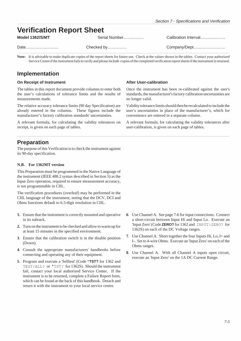
Section 7 - Specifications and Verification
7-5
Verification Report SheetModel 1362/S/MT Serial Number.................. Calibration Interval......................
Date............................. Checked by................. Company/Dept............................
Note: It is advisable to make duplicate copies of the report sheets for future use. Check at the values shown in the tables. Contact your authorizedService Centre if the instrument fails to verify and please include copies of the completed verification report sheets if the instrument is returned.
ImplementationOn Receipt of Instrument
The tables in this report document provide columns to enter boththe user’s calculations of tolerance limits and the results ofmeasurements made.
The relative accuracy tolerance limits (90 day Specification) arealready entered in the columns. These figures include themanufacturer’s factory calibration standards' uncertainties.
A relevant formula, for calculating the validity tolerances onreceipt, is given on each page of tables.
After User-calibration
Once the instrument has been re-calibrated against the user'sstandards, the manufacturer's factory calibration uncertainties areno longer valid.
Validity tolerance limits should then be recalculated to include theuser’s uncertainties in place of the manufacturer’s, which forconvenience are entered in a separate column.
A relevant formula, for calculating the validity tolerances afteruser-calibration, is given on each page of tables.
PreparationThe purpose of this Verification is to check the instrument againstits 90-day specification.
N.B. For 1362MT version
This Preparation must be programmed in the Native Language ofthe instrument (IEEE 488.2 syntax described in Section 5) as theInput Zero operation, required to ensure measurement accuracy,is not programmable in CIIL.
The verification procedures (overleaf) may be performed in theCIIL language of the instrument, noting that the DCV, DCI andOhms functions default to 6.5-digit resolution in CIIL.
1. Ensure that the instrument is correctly mounted and operativein its subrack.
2. Turn on the instrument to be checked and allow to warm up forat least 15 minutes in the specified environment.
3. Ensure that the calibration switch is in the disable position(Down).
4. Consult the appropriate manufacturers' handbooks beforeconnecting and operating any of their equipment.
5. Program and execute a 'Selftest' (Code ∗TST? for 1362 andTEST:ALL? or ∗TST? for 1362S). Should the instrumentfail, contact your local authorized Service Center. If theinstrument is to be returned, complete a Failure Report form,which can be found at the back of this handbook. Detach andreturn it with the instrument to your local service centre.
6. Use Channel A. See page 7-6 for input connections. Connecta short-circuit between Input Hi and Input Lo. Execute an'Input Zero' (Code ZERO? for 1362 and INPUT:ZERO? for1362S) on each of the DC Voltage ranges.
7. Use Channel A. Short together the four Inputs Hi, Lo, I+ andI-. Set to 4-wire Ohms. Execute an 'Input Zero' on each of theOhms ranges.
8. Use Channel A. With all Channel A inputs open circuit,execute an 'Input Zero' on the 1A DC Current Range.
Section 7 - Specifications and Verification
7-6
Procedures
Input Connections
With its output turned off, connect the calibrator output to therelevant input pins of Channel 'A' on the Front Panel INPUTconnector.
Channel 'A' Input Pins(Front Panel Input Connector)
Input PinHi 1I+ 2Lo 5I- 6
Gu 7
DC Voltage
1. Program the 1362 and Calibrator to DC Voltage, 61/2 digits.
2. Set the 1362 to its 100mV DC range and the calibrator to+100mV output. Note the 1362 measured value.
3. Enter the measured value in the top line of Table 1 on page 7-8, under '1362 READING'.
4. Repeat (2) and (3) for the remainder of the 1362 ranges andcalibrator outputs of Table 1.
5. Calculate the 'Validity Tolerance Limits' using the appropriateformula beneath Table 1 on page 7-8.
6. Check that the values in the 1362 READING column are at orwithin the corresponding lower and higher validity tolerancelimits.
AC Voltage
1. Program the 1362 and Calibrator to AC Voltage, 51/2 digits.
2. Set the 1362 to its 100mV AC range and the calibrator to100mV AC output at 1kHz. Note the 1362 measured value.
3. Enter the measured value in the top line of Table 2 on page 7-9, under '1362 READING'.
4. Set the 1362 to its 100mV AC range and the calibrator to100mV AC output at 30kHz. Note the 1362 measured value.
5. Enter the measured value in the second line of Table 2 under'1362 READING'.
6. Repeat (2) to (5) for the remainder of the 1362 ranges andcalibrator outputs of Table 2.
7. Calculate the 'Validity Tolerance Limits' using the appropriateformula beneath Table 3 on page 7-9.
8. Check that the values in the 1362 READING column are at orwithin the corresponding lower and higher validity tolerancelimits.
AC Voltage Linearity Checks
1. Program the 1362 and Calibrator to AC Voltage, 51/2 digits.
2. Set the 1362 to its 10V AC range and the calibrator to 1V ACoutput at 1kHz. Note the 1362 measured value.
3. Enter the measured value in the top line of Table 3 on page 7-9, under '1362 READING'.
4. Increase the calibrator output to 10V AC output at 1kHz. Notethe 1362 measured value.
5. Enter the measured value in the second line of Table 3 under'1362 READING'.
4. Increase the calibrator output to 19V AC output at 1kHz. Notethe 1362 measured value.
5. Enter the measured value in the third line of Table 3 under'1362 READING'.
6. Calculate the 'Validity Tolerance Limits' using the appropriateformula beneath Table 3 on page 7-9.
7. Check that the values in the 1362 READING column are at orwithin the corresponding lower and higher validity tolerancelimits.
WARNING THIS INSTRUMENT CAN DELIVER ALETHAL ELECTRIC SHOCK. NEVERTOUCH ANY LEAD OR TERMINAL UNLESSYOU ARE ABSOLUTELY CERTAIN THATNO DANGEROUS VOLTAGE IS PRESENT.
WARNING
In the following sequences, when changingconnections or switching ranges, ensure that thecalibrator output is switched or programmed off.
Section 7 - Specifications and Verification
7-7
Resistance
1. Program the 1362 and Calibrator to Ohms, 61/2 digits, 4-wireconnection.
2. Set the 1362 to its 100Ω range and the calibrator to 100Ωnominal output.
3. Enter the calibrator resistance value in the top line of Table 4on page 7-10, under 'Calibrator Resistance Value'. Calculateand enter δR in its column.
4. Note the 1362 measured value. Enter the value in the top lineof Table 4 under '1362 READING'.
5. Repeat (2) to (4) for the remainder of the 1362 ranges andcalibrator resistances of Table 4.
6. Calculate the 'Validity Tolerance Limits' using the appropriateformula beneath Table 4 on page 7-10.
7. Check that the values in the 1362 READINGS column are ator within the corresponding lower and higher validitytolerance limits.
DC Current
1. Program the 1362 and Calibrator to DC Current, 61/2 digits.
2. Set the 1362 to its 1000mA DC range and the calibrator to+1000mA output. Note the 1362 measured value.
3. Enter the measured value in the top line of Table 5 on page 7-11, under '1362 READING'.
4. Set the 1362 to its 1000mA DC range and the calibrator to -1000mA output. Note the 1362 measured value.
5. Enter the measured value in the second line of Table 5 under'1362 READING'.
6. Calculate the 'Validity Tolerance Limits' using the appropriateformula beneath Table 6 on page 7-11.
7. Check that the value in the 1362 READING column is at orwithin the lower and higher validity tolerance limits.
AC Current
1. Program the 1362 and Calibrator to AC Current, 51/2 digits
2. Set the 1362 to its 1000mA AC range and the calibrator to1000mA AC output at 10kHz. Note the 1362 measured value.
3. Enter the measured value in the top line of Table 6 on page 7-11, under '1362 READING'.
4. Calculate the 'Validity Tolerance Limits' using the appropriateformula beneath Table 6.
5. Check that the value in the 1362 READING column is at orwithin the corresponding lower and higher validity tolerancelimits.
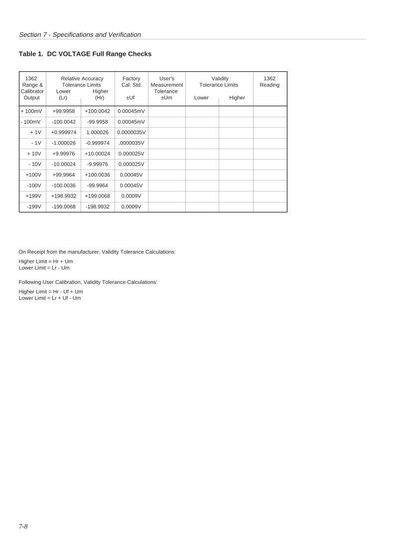
Section 7 - Specifications and Verification
7-8
Table 1. DC VOLTAGE Full Range Checks
+ 100mV +99.9958 +100.0042 0.00045mV
- 100mV -100.0042 -99.9958 0.00045mV
+ 1V +0.999974 1.000026 0.0000035V
- 1V -1.000026 -0.999974 .0000035V
+ 10V +9.99976 +10.00024 0.000025V
- 10V -10.00024 -9.99976 0.000025V
+100V +99.9964 +100.0036 0.00045V
-100V -100.0036 -99.9964 0.00045V
+199V +198.9932 +199.0068 0.0009V
-199V -199.0068 -198.9932 0.0009V
1362 Relative Accuracy Factory User's Validity 1362 Range & Tolerance Limits Cal. Std. Measurement Tolerance Limits ReadingCalibrator Lower Higher Tolerance Output (Lr) (Hr) ±Uf ±Um Lower Higher
On Receipt from the manufacturer, Validity Tolerance Calculations:
Higher Limit = Hr + UmLower Limit = Lr - Um
Following User Calibration, Validity Tolerance Calculations:
Higher Limit = Hr - Uf + UmLower Limit = Lr + Uf - Um
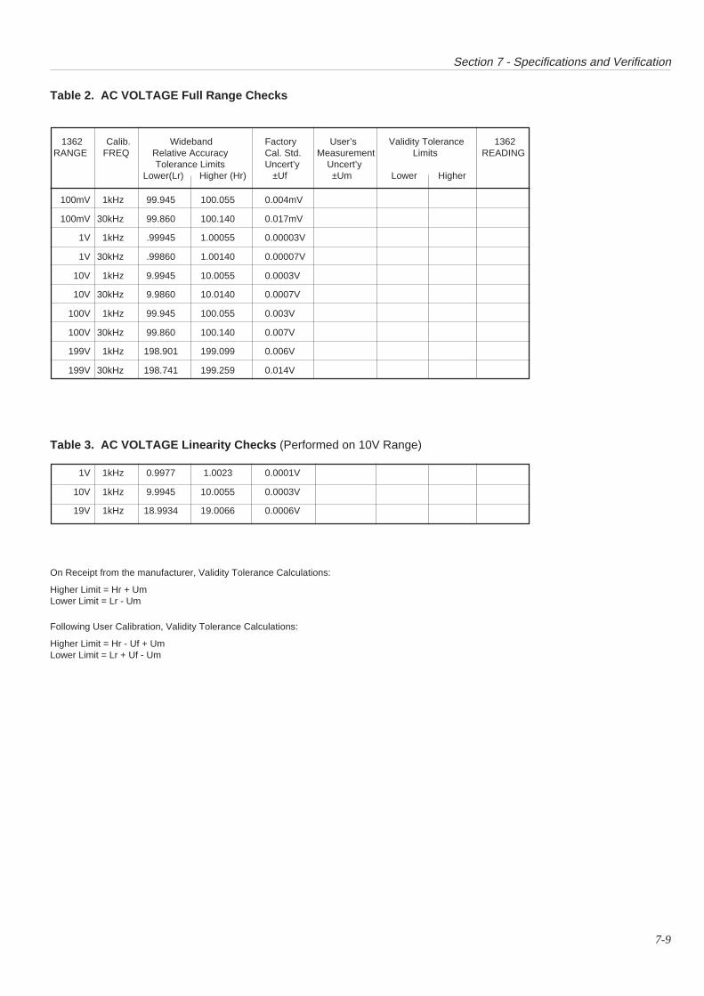
Section 7 - Specifications and Verification
7-9
1362 Calib. Wideband Factory User’s Validity Tolerance 1362RANGE FREQ Relative Accuracy Cal. Std. Measurement Limits READING
Tolerance Limits Uncert’y Uncert’y Lower(Lr) Higher (Hr) ±Uf ±Um Lower Higher
Table 2. AC VOLTAGE Full Range Checks
100mV 1kHz 99.945 100.055 0.004mV
100mV 30kHz 99.860 100.140 0.017mV
1V 1kHz .99945 1.00055 0.00003V
1V 30kHz .99860 1.00140 0.00007V
10V 1kHz 9.9945 10.0055 0.0003V
10V 30kHz 9.9860 10.0140 0.0007V
100V 1kHz 99.945 100.055 0.003V
100V 30kHz 99.860 100.140 0.007V
199V 1kHz 198.901 199.099 0.006V
199V 30kHz 198.741 199.259 0.014V
Table 3. AC VOLTAGE Linearity Checks (Performed on 10V Range)
1V 1kHz 0.9977 1.0023 0.0001V
10V 1kHz 9.9945 10.0055 0.0003V
19V 1kHz 18.9934 19.0066 0.0006V
On Receipt from the manufacturer, Validity Tolerance Calculations:
Higher Limit = Hr + UmLower Limit = Lr - Um
Following User Calibration, Validity Tolerance Calculations:
Higher Limit = Hr - Uf + UmLower Limit = Lr + Uf - Um
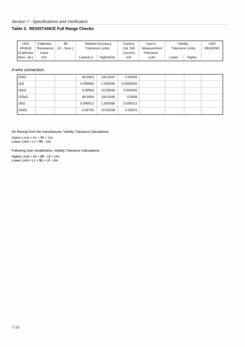
Section 7 - Specifications and Verification
7-10
1362 Calibrator δR Relative Accuracy Factory User’s Validity 1362 RANGE Resistance (Vr - Nom.) Tolerance Limits Cal. Std Measurement Tolerance Limits READING(Calibrator Value Uncert’y ToleranceNom. val.) (Vr) Lower(Lr) Higher(Hr) ±Uf ±Um Lower Higher
100Ω 99.9953 100.0047 0.00045
1kΩ 0.999964 1.000036 0.0000045
10kΩ 9.99964 10.00036 0.000045
100kΩ 99.9954 100.0046 0.0008
1MΩ 0.999912 1.000088 0.000012
10MΩ 9.99792 10.00208 0.00015
On Receipt from the manufacturer, Validity Tolerance Calculations:
Higher Limit = Hr + δR + UmLower Limit = Lr + δR - Um
Following User recalibration, Validity Tolerance Calculations:
Higher Limit = Hr + δR - Uf + UmLower Limit = Lr + δR + Uf - Um
Table 3. RESISTANCE Full Range Checks
4-wire connection
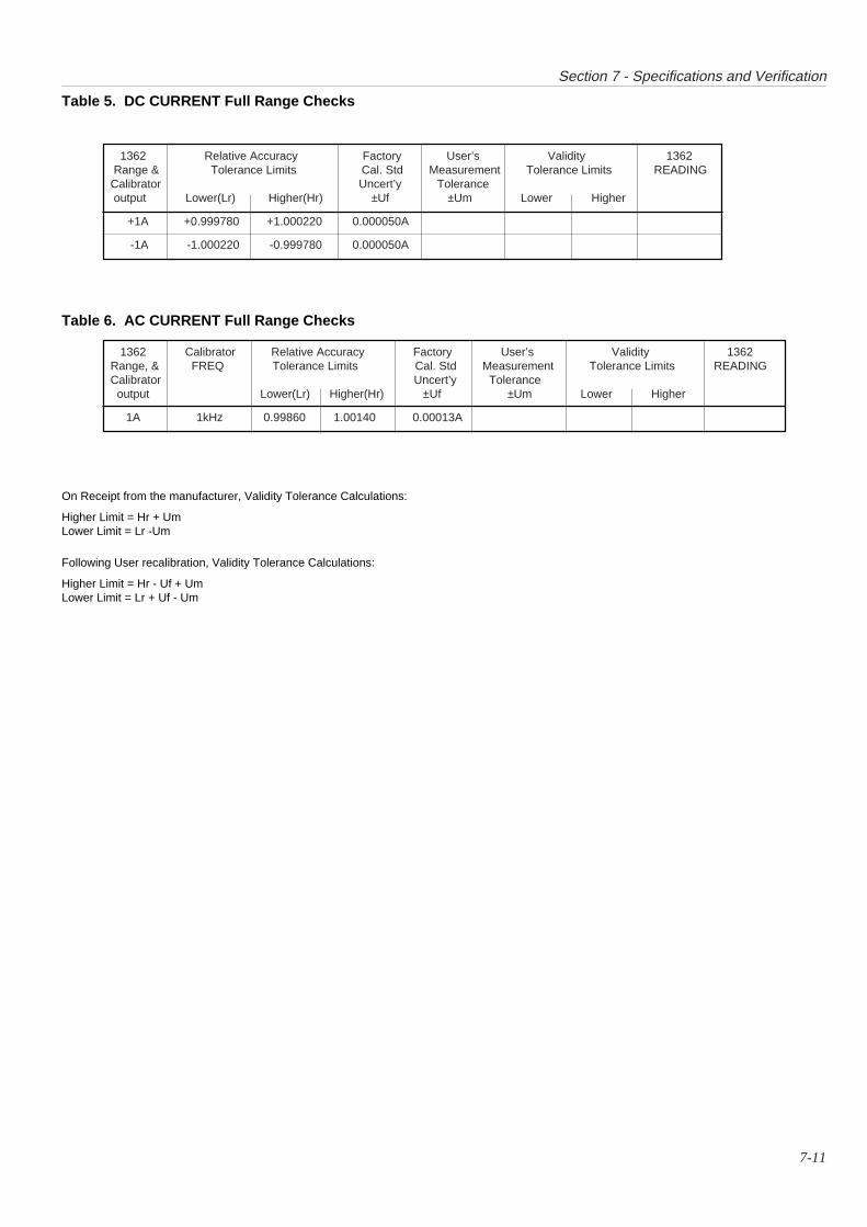
Section 7 - Specifications and Verification
7-11
1362 Relative Accuracy Factory User’s Validity 1362 Range & Tolerance Limits Cal. Std Measurement Tolerance Limits READING Calibrator Uncert’y Tolerance output Lower(Lr) Higher(Hr) ±Uf ±Um Lower Higher
+1A +0.999780 +1.000220 0.000050A
-1A -1.000220 -0.999780 0.000050A
1362 Calibrator Relative Accuracy Factory User’s Validity 1362 Range, & FREQ Tolerance Limits Cal. Std Measurement Tolerance Limits READING Calibrator Uncert’y Tolerance output Lower(Lr) Higher(Hr) ±Uf ±Um Lower Higher
1A 1kHz 0.99860 1.00140 0.00013A
Table 6. AC CURRENT Full Range Checks
Table 5. DC CURRENT Full Range Checks
On Receipt from the manufacturer, Validity Tolerance Calculations:
Higher Limit = Hr + UmLower Limit = Lr -Um
Following User recalibration, Validity Tolerance Calculations:
Higher Limit = Hr - Uf + UmLower Limit = Lr + Uf - Um

this page deliberately left blank

SECTION 81362 ROUTINE CALIBRATION
8-1

Section 8 - Routine Calibration
8-2
SECTION 8 1362 ROUTINE CALIBRATION
1. Ensure that the instrument is correctly mounted and operative inits subrack.
2. Turn on the instrument and allow to warm up for at least 15minutes in the specified environment.
3. Ensure that the front panel calibration switch is in the disableposition (Down).
4. Program and execute a 'Selftest' (Query ∗TST?). Should theinstrument fail, contact your local authorized Service Center. Ifthe instrument is to be returned, complete a Failure Report form,which can be found at the back of this handbook. Detach andreturn it with the instrument to your local service centre.
5. Set the calibration switch to the enable position (Up).6. Use the LINE Nrf code to select the appropriate Line Frequency
and Integration mode (page 5-32).Note: If a partial calibration is being attempted, use the same line
frequency as for the most-recent main calibration. If thelocal line frequency differs from the cal frequency, ensurethat common mode noise on the input signal is minimized.
7. Use the CAL ON code to enable calibration mode (page 5-29).8. If required, use the STLN? query to store the currently-selected
line frequency as the Power On Default setting (the currentdefault can be read using the LINE? query). (page 5-32).
To disable calibration mode at any time, either send CAL OFF orset the front panel calibration switch to the disable position(Down) (page 5-29).
Preparation
After Routine Calibration
Once the instrument has been re-calibrated against the user'sstandards, its performance can be verified against the calibrationstandards as detailed in Section 7.
Note: The manufacturer's factory calibration uncertainties are nolonger valid after user-recalibration, so when performingthe calculations in Section 7, the validity tolerance limitsshould be calculated to include the user’s calibrationuncertainties in place of the manufacturer’s.
Introduction
Equipment Requirements
Basic Configuration (including Option 40):DC and AC Voltage and Resistance Calibrator of suitableaccuracy.e.g Model 4800 or 4808
(Options 10, 20, 30 & 50)
Full Analog Configuration (including Option 30):DC and AC Voltage, DC and AC Current, and ResistanceCalibrator of suitable accuracy.e.g Model 4800 or 4808
(Options 10, 20, 30, 40 & 50)
Non-Nominal Calibration
The levels at which calibration is performed, given in thefollowing procedures, are the 'nominal' points for the functions/ranges. Nominal points need not be programmed; they areassumed by the 1362 when the commands CALL? and CALH?are sent without Nrf.
For users who wish to calibrate at non-nominal values, CALL?and CALH? allow the non-nominal value to be entered in 'Nrf'form. This causes the 1362 to assume that the value representedby the Nrf is that which will be input.
There is a high probability that nominal resistance values will notbe available; this is reflected in the 4-wire procedure at operation7 on page 8-4.
An Nrf in the following ranges of values is valid:
With CALL? - any value up to +25% of full range, except for theDCV or ACV 300V range: 75V.
With CALH? - any value between 75% of full range and fullscale.
Refer to Section 5, page 5-29.)
NB. This calibration routine was developed for a 1362 using Native language. To calibrate using SCPI, follow this procedure buttranspose the calibration commands for those detailed in Section 4; pages 4-12 & 4-13. Calibration is not programmable in CIIL.
Read This First
To verify the instrument specification without affecting the cali-bration memory, please refer to Section 7 of this handbook.
For information on other forms of calibration, such as the types ofrepairs which must be followed by calibration, refer to yourauthorized service center. The instrument must be thoroughlychecked before attempting calibration.
WARNING THIS INSTRUMENT CAN DELIVER ALETHAL ELECTRIC SHOCK. NEVERTOUCH ANY LEAD OR TERMINAL UNLESSYOU ARE ABSOLUTELY CERTAIN THATNO DANGEROUS VOLTAGE IS PRESENT.
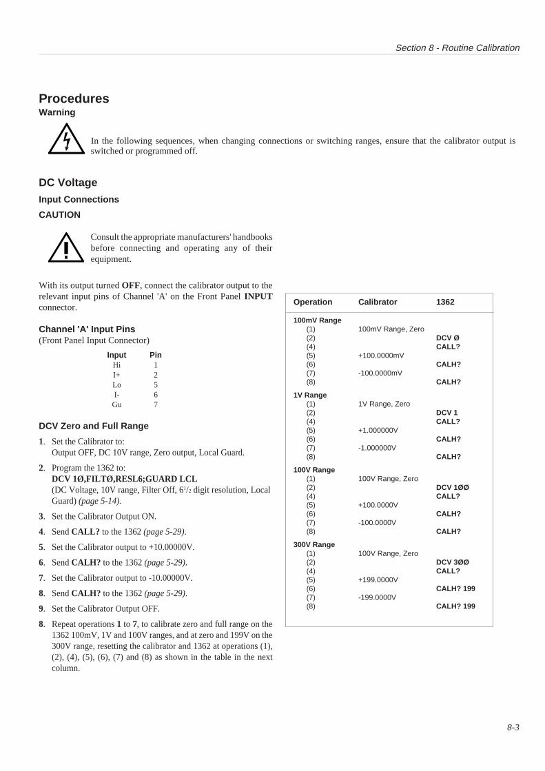
Section 8 - Routine Calibration
8-3
DC VoltageInput Connections
CAUTION
Consult the appropriate manufacturers' handbooksbefore connecting and operating any of theirequipment.
With its output turned OFF, connect the calibrator output to therelevant input pins of Channel 'A' on the Front Panel INPUTconnector.
Channel 'A' Input Pins(Front Panel Input Connector)
Input PinHi 1I+ 2Lo 5I- 6
Gu 7
DCV Zero and Full Range
1. Set the Calibrator to:Output OFF, DC 10V range, Zero output, Local Guard.
2. Program the 1362 to:DCV 1Ø,FILTØ,RESL6;GUARD LCL(DC Voltage, 10V range, Filter Off, 61/2 digit resolution, LocalGuard) (page 5-14).
3. Set the Calibrator Output ON.
4. Send CALL? to the 1362 (page 5-29).
5. Set the Calibrator output to +10.00000V.
6. Send CALH? to the 1362 (page 5-29).
7. Set the Calibrator output to -10.00000V.
8. Send CALH? to the 1362 (page 5-29).
9. Set the Calibrator Output OFF.
8. Repeat operations 1 to 7, to calibrate zero and full range on the1362 100mV, 1V and 100V ranges, and at zero and 199V on the300V range, resetting the calibrator and 1362 at operations (1),(2), (4), (5), (6), (7) and (8) as shown in the table in the nextcolumn.
Operation Calibrator 1362
100mV Range(1) 100mV Range, Zero(2) DCV Ø(4) CALL?(5) +100.0000mV(6) CALH?(7) -100.0000mV(8) CALH?
1V Range(1) 1V Range, Zero(2) DCV 1(4) CALL?(5) +1.000000V(6) CALH?(7) -1.000000V(8) CALH?
100V Range(1) 100V Range, Zero(2) DCV 1ØØ(4) CALL?(5) +100.0000V(6) CALH?(7) -100.0000V(8) CALH?
300V Range(1) 100V Range, Zero(2) DCV 3ØØ(4) CALL?(5) +199.0000V(6) CALH? 199(7) -199.0000V(8) CALH? 199
ProceduresWarning
In the following sequences, when changing connections or switching ranges, ensure that the calibrator output isswitched or programmed off.

Section 8 - Routine Calibration
8-4
ResistanceInput Connections
CAUTION
Consult the appropriate manufacturers' handbooksbefore connecting and operating any of theirequipment.
With its output turned OFF, connect the calibrator output to therelevant input pins of Channel 'A' on the Front Panel INPUTconnector.
Channel 'A' Input Pins(Front Panel Input Connector)
Input PinHi 1I+ 2Lo 5I- 6
Gu 7
4-Wire Zero and Full Range
1. Set the Calibrator to:Output OFF, ZeroΩ, Remote Guard.
2. Program the 1362 to:OHMS 1ØØ,FILTØ,RESL6,WIRE4;GUARD LCL(Ohms, 100Ω range, Filter Off, 61/2 digit resolution, 4-wireconnection,Local Guard) (page 5-18).
3. Set the Calibrator Output ON. (If a four-wire zero is not availableon the calibrator, disconnect the calibrator and connect a short-circuit between pins 1, 2, 5, and 6 of the 1362 input connectorinstead, using the shortest possible wire.)
4. Send CALL? to the 1362 (page 5-29).
5. If a short-circuit was connected at operation (3), disconnect it andreconnect the calibrator leads.
6. Set the Calibrator output to 100Ω. (If nominal value is notavailable, see operation (7) regarding the use of CALH? Nrf .
7. Send CALH? to the 1362 for calibration at nominal value(CALH? Nrf for non-nominal calibration).(Nrf is the non-nominal value of the calibrator's output) (page 5-29).
8. Set the Calibrator Output OFF.
9. Repeat operations 1 to 8, to calibrate zero and full range on the1kΩ, 10kΩ, 100kΩ, 1MΩ and 10MΩ ranges, resetting thecalibrator and 1362 at operations (1), (2), (4), (6) and (7) as shownin the table in the next column (table shows settings for nominalvalues).
2-Wire Zero
1. Disconnect the Calibrator. Connect a short-circuit betweenChannel A Hi and Lo on the front panel input connector (pins 1and 5). Use the shortest length of wire possible.
2. Program the 1362 to:OHMS 1ØØ,FILTØ,RESL6,WIRE2;GUARD LCL(Ohms, 100Ω range, Filter Off, 61/2 digit resolution, 2-wireconnection,Local Guard) (page 5-18).
3. Send CALL? to the 1362 (page 5-29).
4. Repeat operations (2) and (3) for the 1kΩ range (OHMS1ØØØ,WIRE2 only at operation (2)).
5. Repeat operations (2) and (3) for the 10kΩ range (OHMS1ØØØØ,WIRE2 only at operation (2)).
6. Repeat operations (2) and (3) for the 100kΩ range (OHMS1ØØØØØ,WIRE2 only at operation (2)).
7. Repeat operations (2) and (3) for the 1MΩ range (OHMS1ØØØØØØ,FILT1,WIRE2 only at operation (2)).
8. Repeat operations (2) and (3) for the 10MΩ range (OHMS1ØØØØØØØ,FILT1,WIRE2 only at operation (2)).
Operation Calibrator 1362
1kΩ Range(1) ZeroΩ(2) OHMS 1ØØØ(4) CALL?(6) 1000.000Ω(7) CALH?
10kΩ Range(1) ZeroΩ(2) OHMS 1ØØØØ(4) CALL?(6) 10,000.00Ω(7) CALH?
100kΩ Range(1) ZeroΩ(2) OHMS 1ØØØØØ(4) CALL?(6) 100,000.0Ω(7) CALH?
1MΩ Range(1) ZeroΩ(2) OHMS 1ØØØØØØ,FILT1(4) CALL?(6) 1,000,000Ω(7) CALH?
10MΩ Range(1) ZeroΩ(2) OHMS 1ØØØØØØØ,FILT1(4) CALL?(6) 10,000.00kΩ(7) CALH?
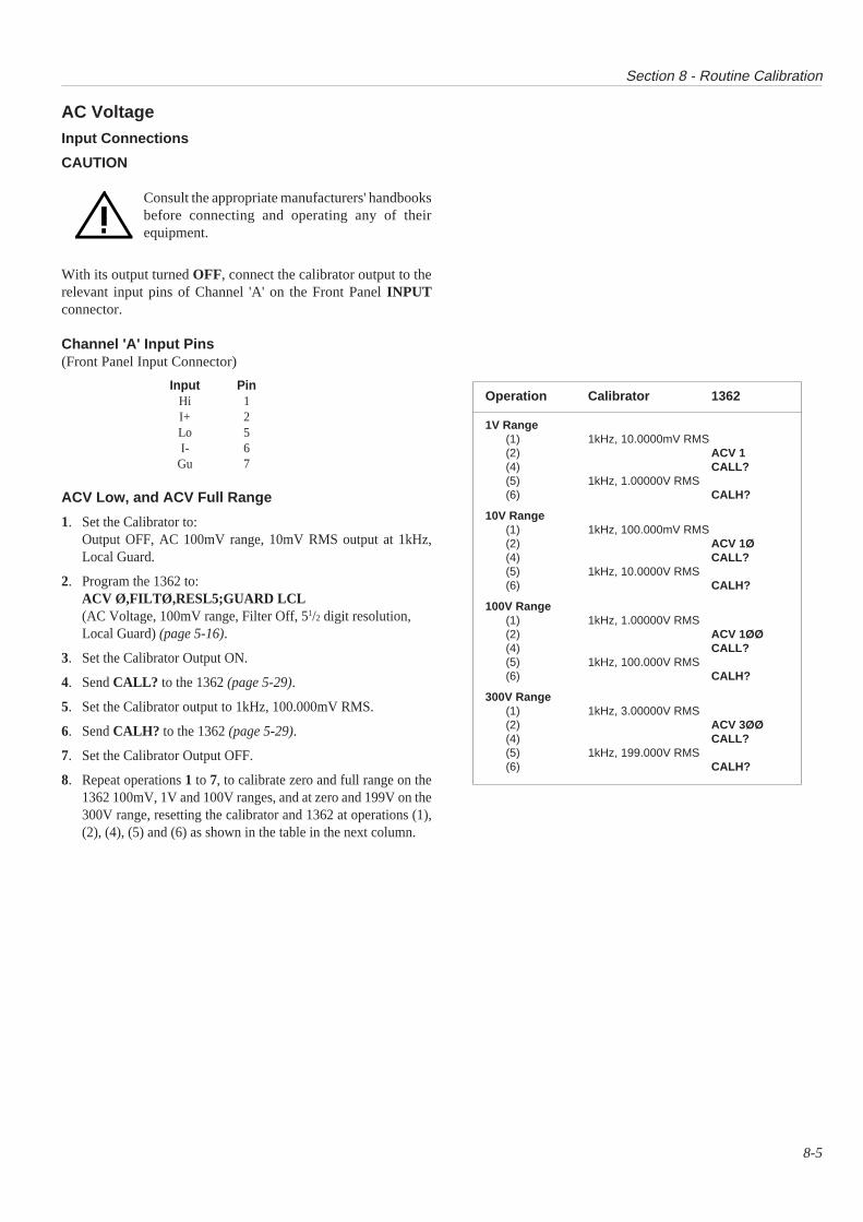
Section 8 - Routine Calibration
8-5
AC VoltageInput Connections
CAUTION
Consult the appropriate manufacturers' handbooksbefore connecting and operating any of theirequipment.
With its output turned OFF, connect the calibrator output to therelevant input pins of Channel 'A' on the Front Panel INPUTconnector.
Channel 'A' Input Pins(Front Panel Input Connector)
Input PinHi 1I+ 2Lo 5I- 6
Gu 7
ACV Low, and ACV Full Range
1. Set the Calibrator to:Output OFF, AC 100mV range, 10mV RMS output at 1kHz,Local Guard.
2. Program the 1362 to:ACV Ø,FILTØ,RESL5;GUARD LCL(AC Voltage, 100mV range, Filter Off, 51/2 digit resolution,Local Guard) (page 5-16).
3. Set the Calibrator Output ON.
4. Send CALL? to the 1362 (page 5-29).
5. Set the Calibrator output to 1kHz, 100.000mV RMS.
6. Send CALH? to the 1362 (page 5-29).
7. Set the Calibrator Output OFF.
8. Repeat operations 1 to 7, to calibrate zero and full range on the1362 100mV, 1V and 100V ranges, and at zero and 199V on the300V range, resetting the calibrator and 1362 at operations (1),(2), (4), (5) and (6) as shown in the table in the next column.
Operation Calibrator 1362
1V Range(1) 1kHz, 10.0000mV RMS(2) ACV 1(4) CALL?(5) 1kHz, 1.00000V RMS(6) CALH?
10V Range(1) 1kHz, 100.000mV RMS(2) ACV 1Ø(4) CALL?(5) 1kHz, 10.0000V RMS(6) CALH?
100V Range(1) 1kHz, 1.00000V RMS(2) ACV 1ØØ(4) CALL?(5) 1kHz, 100.000V RMS(6) CALH?
300V Range(1) 1kHz, 3.00000V RMS(2) ACV 3ØØ(4) CALL?(5) 1kHz, 199.000V RMS(6) CALH?
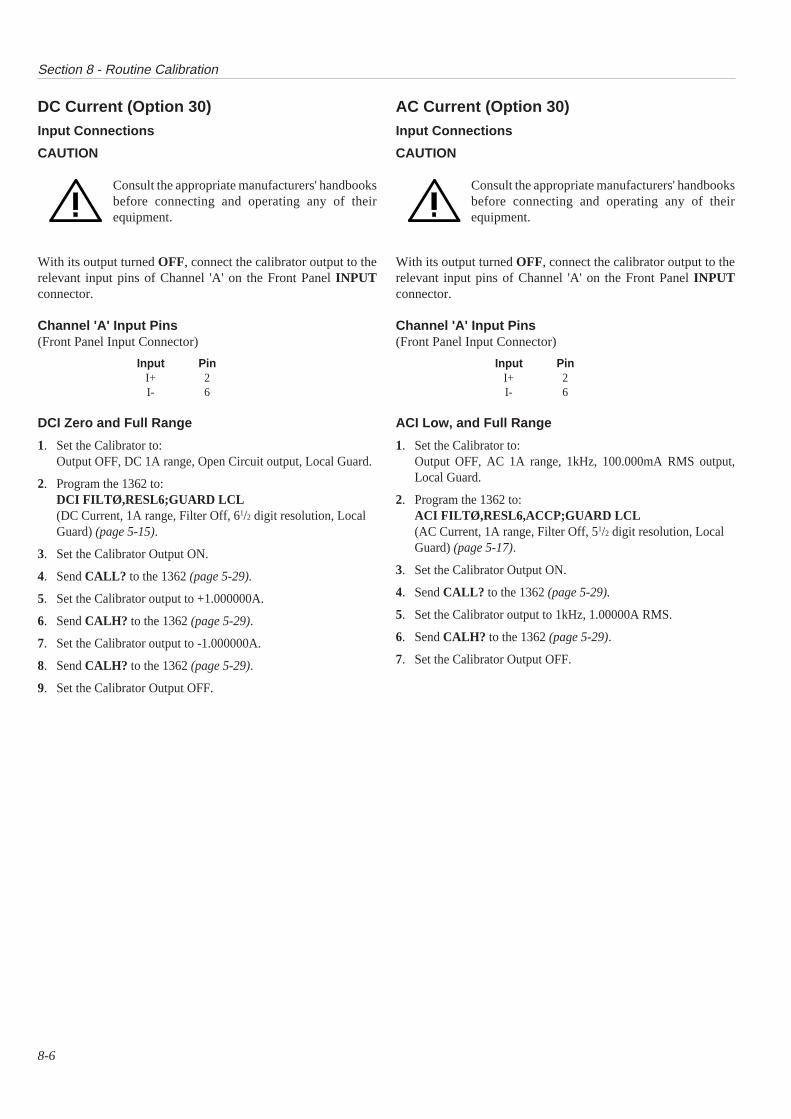
Section 8 - Routine Calibration
8-6
DC Current (Option 30)Input Connections
CAUTION
Consult the appropriate manufacturers' handbooksbefore connecting and operating any of theirequipment.
With its output turned OFF, connect the calibrator output to therelevant input pins of Channel 'A' on the Front Panel INPUTconnector.
Channel 'A' Input Pins(Front Panel Input Connector)
Input PinI+ 2I- 6
DCI Zero and Full Range
1. Set the Calibrator to:Output OFF, DC 1A range, Open Circuit output, Local Guard.
2. Program the 1362 to:DCI FILTØ,RESL6;GUARD LCL(DC Current, 1A range, Filter Off, 61/2 digit resolution, LocalGuard) (page 5-15).
3. Set the Calibrator Output ON.
4. Send CALL? to the 1362 (page 5-29).
5. Set the Calibrator output to +1.000000A.
6. Send CALH? to the 1362 (page 5-29).
7. Set the Calibrator output to -1.000000A.
8. Send CALH? to the 1362 (page 5-29).
9. Set the Calibrator Output OFF.
AC Current (Option 30)Input Connections
CAUTION
Consult the appropriate manufacturers' handbooksbefore connecting and operating any of theirequipment.
With its output turned OFF, connect the calibrator output to therelevant input pins of Channel 'A' on the Front Panel INPUTconnector.
Channel 'A' Input Pins(Front Panel Input Connector)
Input PinI+ 2I- 6
ACI Low, and Full Range
1. Set the Calibrator to:Output OFF, AC 1A range, 1kHz, 100.000mA RMS output,Local Guard.
2. Program the 1362 to:ACI FILTØ,RESL6,ACCP;GUARD LCL(AC Current, 1A range, Filter Off, 51/2 digit resolution, LocalGuard) (page 5-17).
3. Set the Calibrator Output ON.
4. Send CALL? to the 1362 (page 5-29).
5. Set the Calibrator output to 1kHz, 1.00000A RMS.
6. Send CALH? to the 1362 (page 5-29).
7. Set the Calibrator Output OFF.

Section 11 - Servicing Diagrams
11-1
Contents
N.B. 1. Component Lists appear in Section 12.2. The pages in this section are not numbered, but the Diagrams are placed in the following order.
Assembly Description Layout Drawings Circuit Diagrams
SECTION 11 1362 Servicing Diagrams
1362 Finished Assembly1362S Finished Assembly1362MT Finished Assembly
DA400910 Shts 1 & 2DA401080 Shts 1 & 2DA400952 Shts 1 & 2
---------
Card DMM Assembly Layout Drawing DA400911 Circuit Diagram DC400911
Sht Detail Sht DetailNo. No.
1 Full Board Layout 1 Processor and Memory2 Rear Section Detail 2 Serial Interface3 Mid Section Detail 3 Digital Connections4 Front Section Detail 4 Digital Subsystem
& VME Interface5 RMS Converter6 AC Preamp7 A to D Converter8 DC Preamp9 Power Supplies
10 Self-Test Subsystem11 Floating Ohms12 Control13 Input and A-D Optos14 VXI I/F Chip
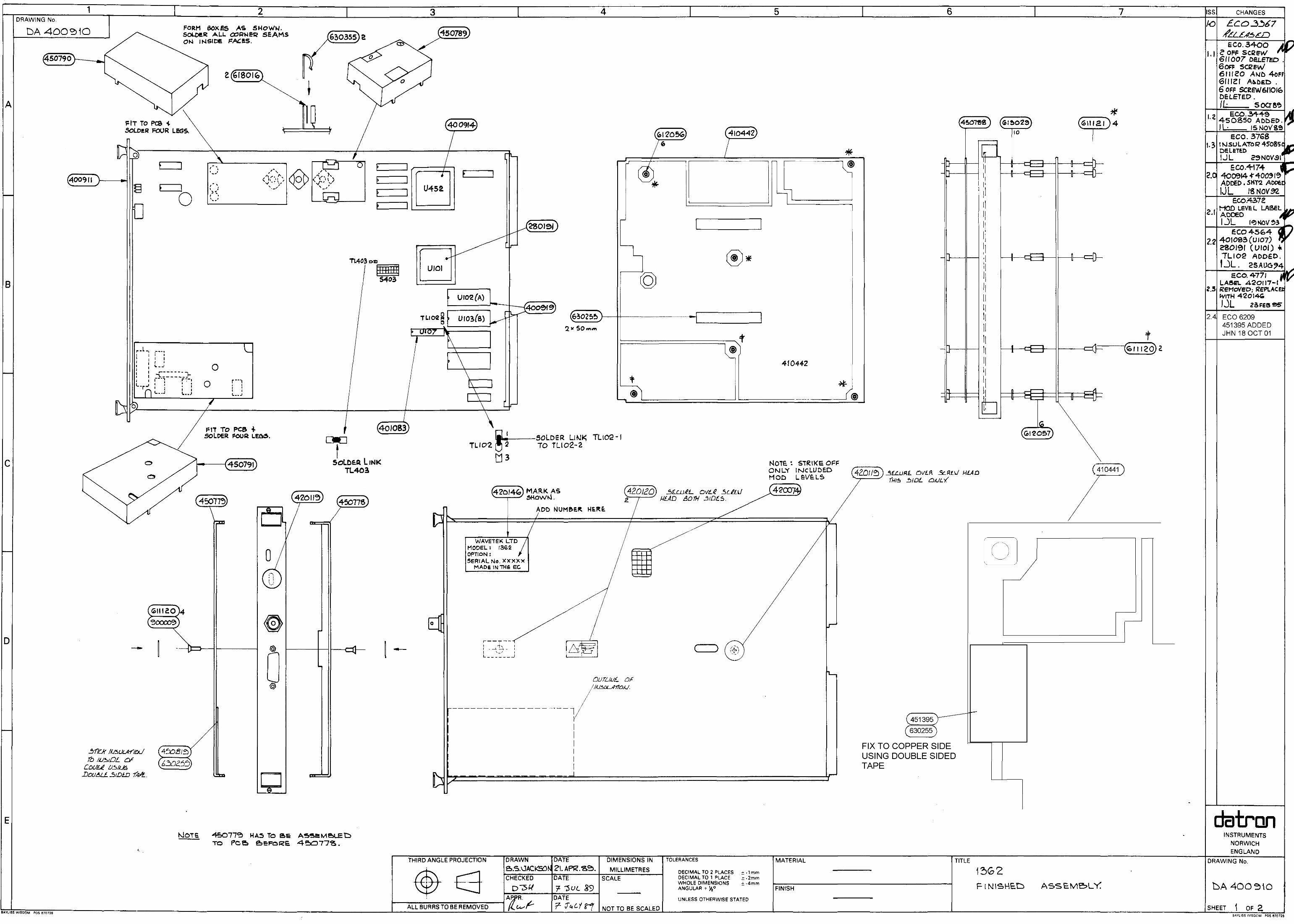
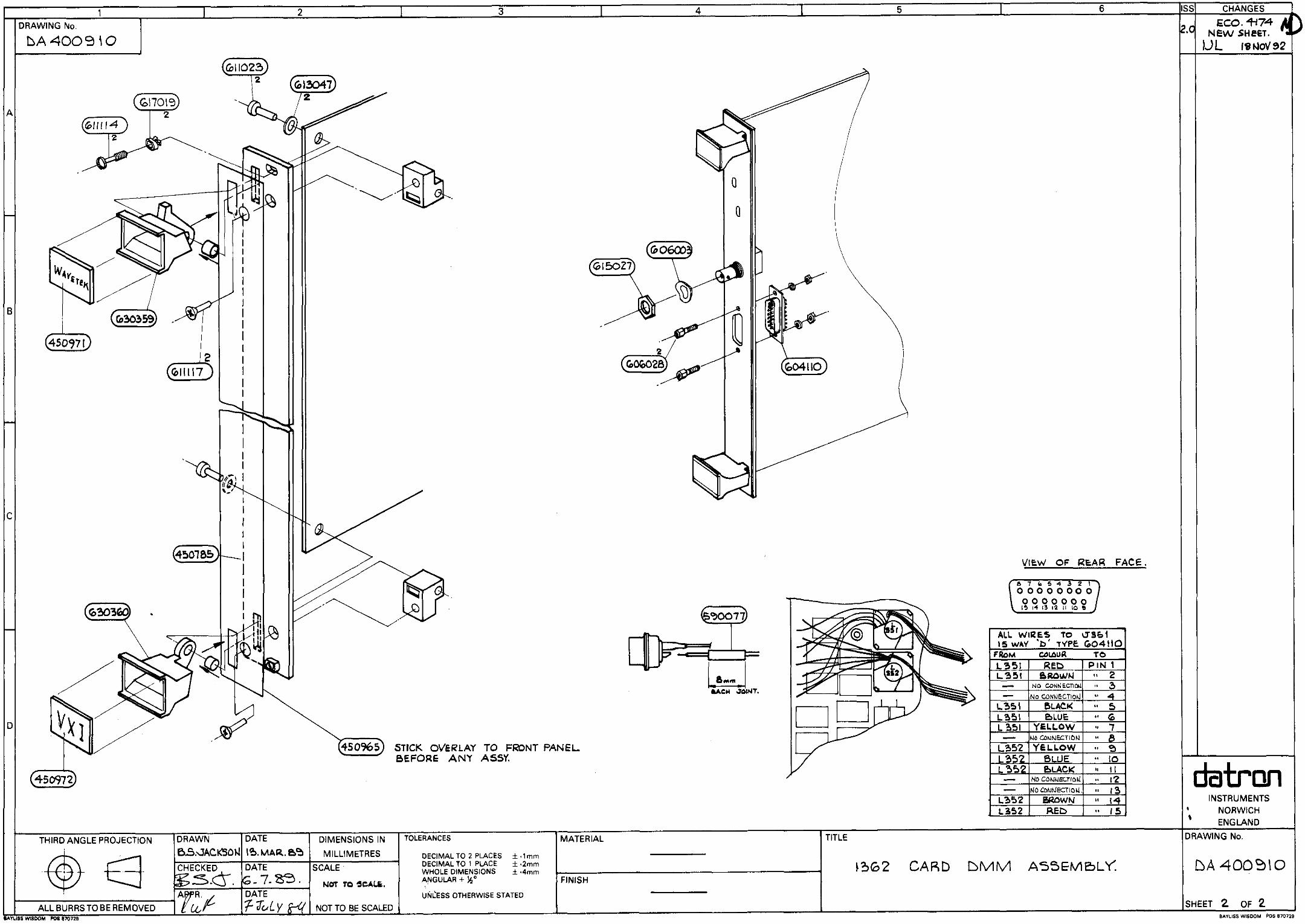
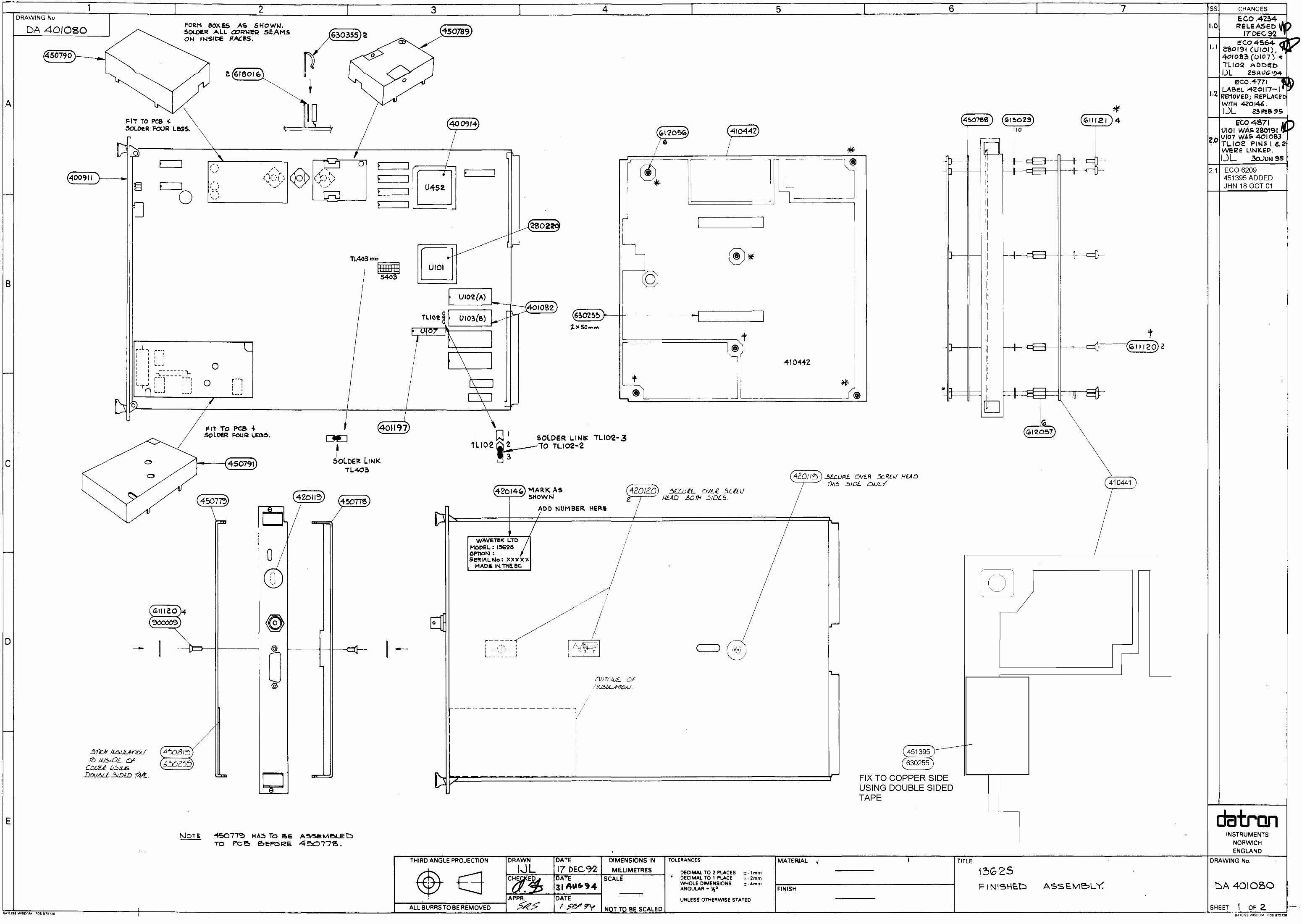
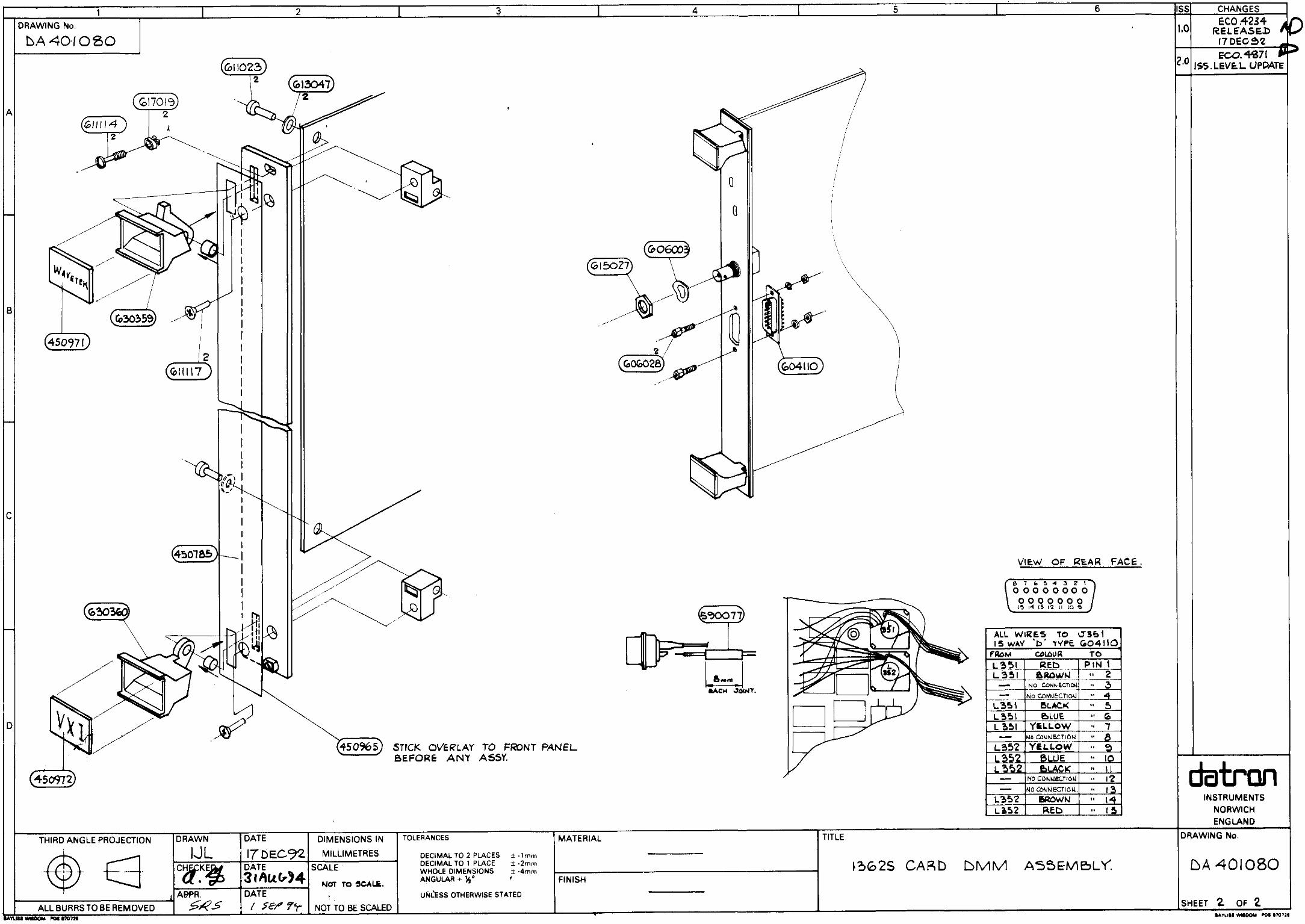


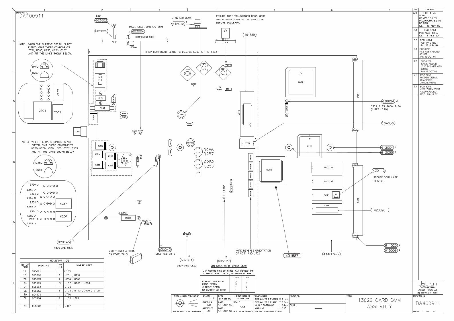
U202
401587
6.1 ECO 6208PCB ASSY ADDED401587JHN 16 OCT 01
401589
604171
6.2 ECO 6209401589 ADDEDU710 SOCKET WAS605050JHN 19 OCT 01
6.3 ECO 6232HIDDEN DETAILCLARIFIED.JHN 23 JAN 02
6.4 ECO 6256420117 REMOVED420098 ADDEDRCG 05 JUL 02
420098
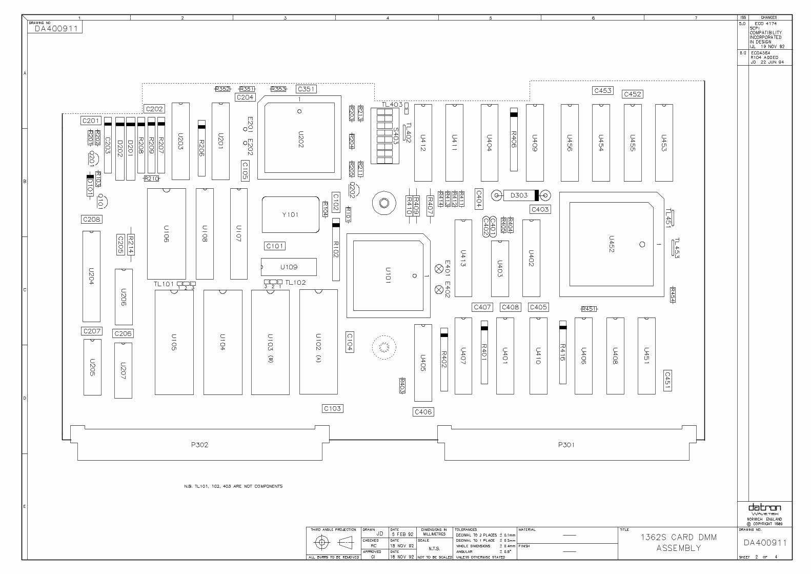
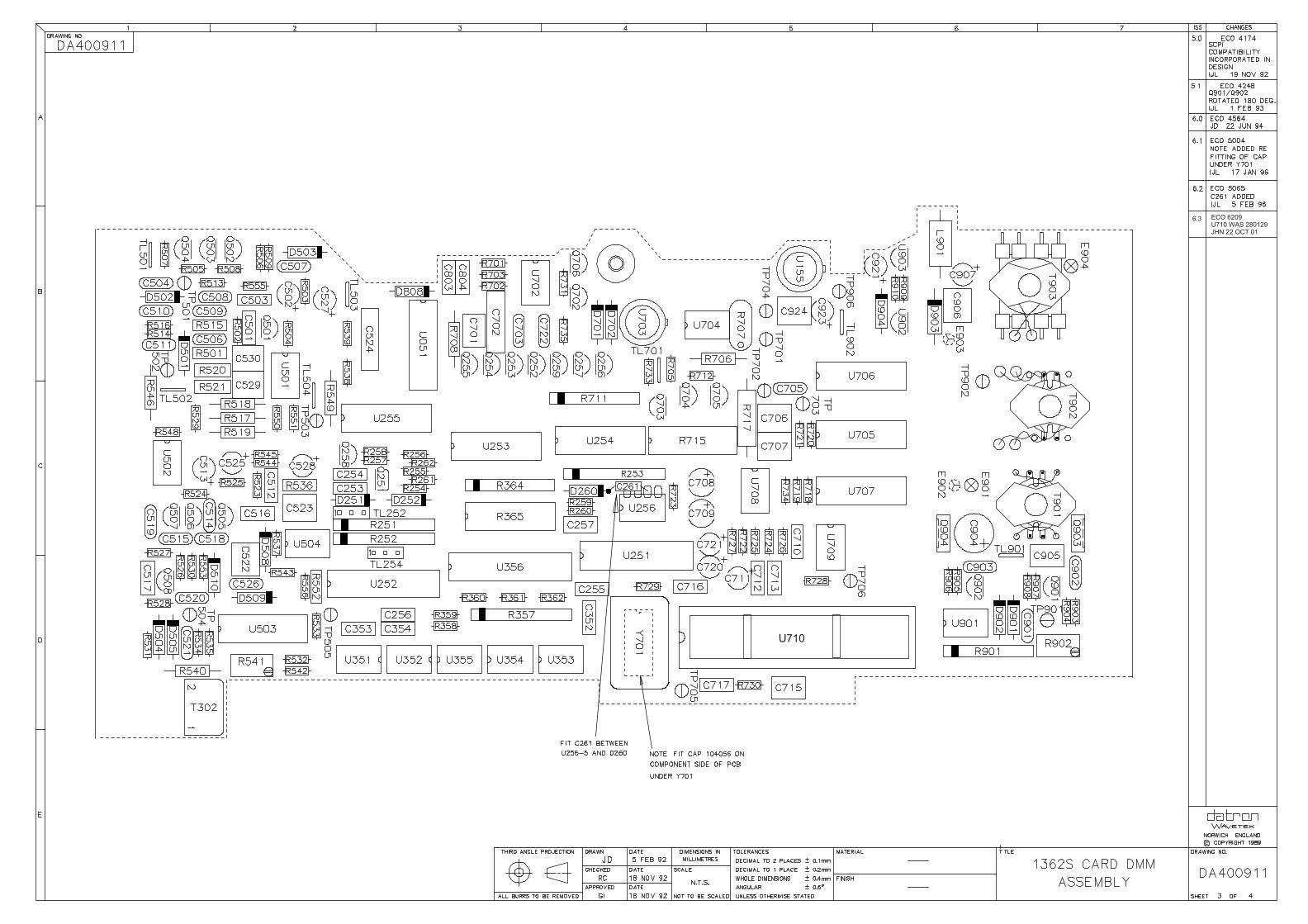
U710
6.3 ECO 6209U710 WAS 280129JHN 22 OCT 01

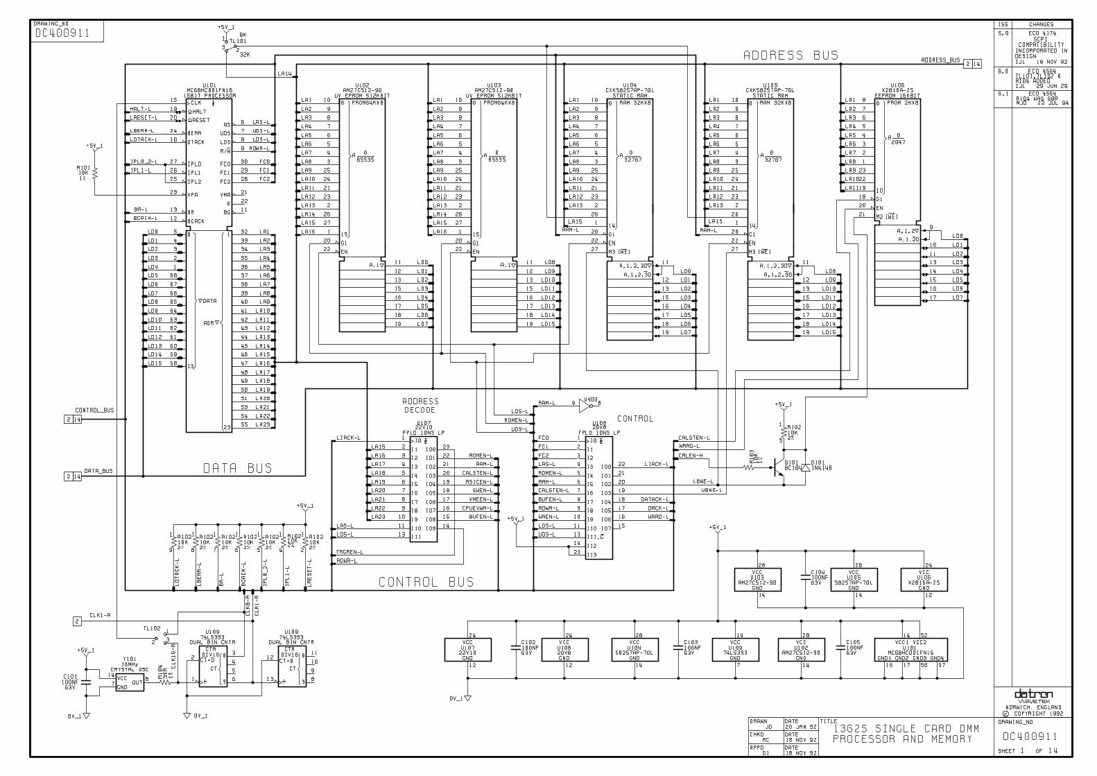
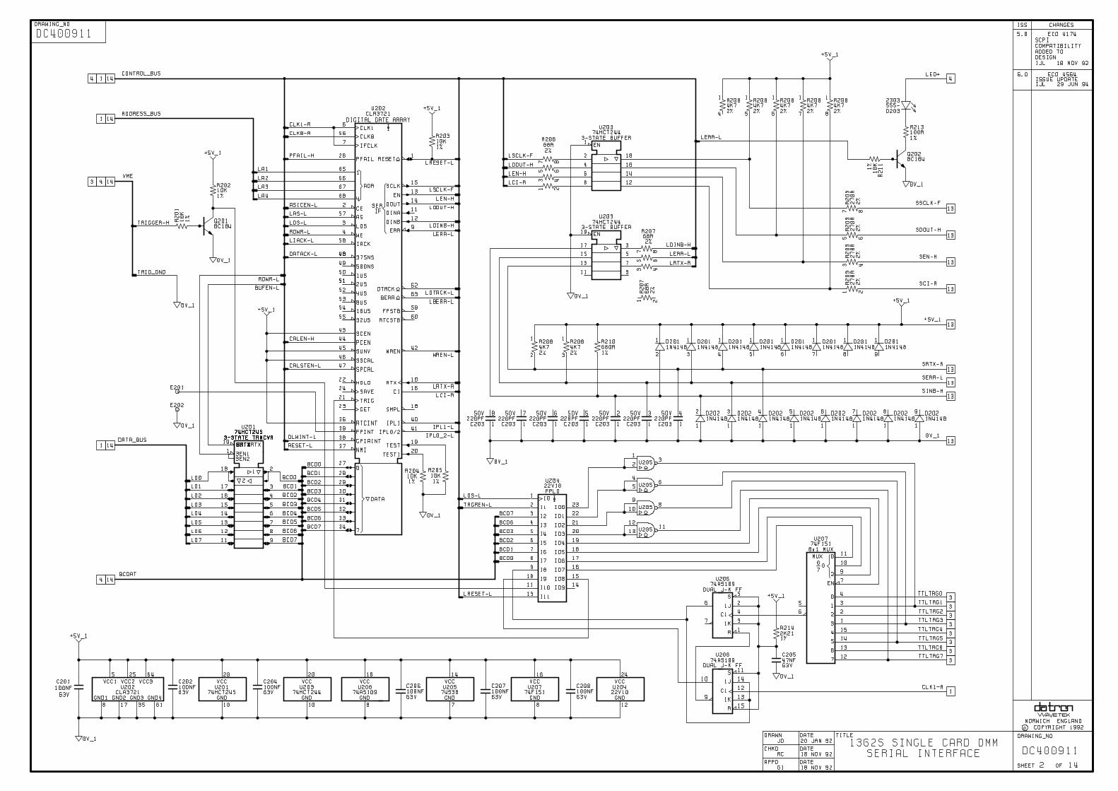
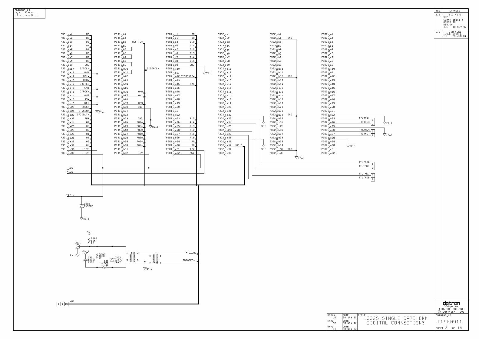
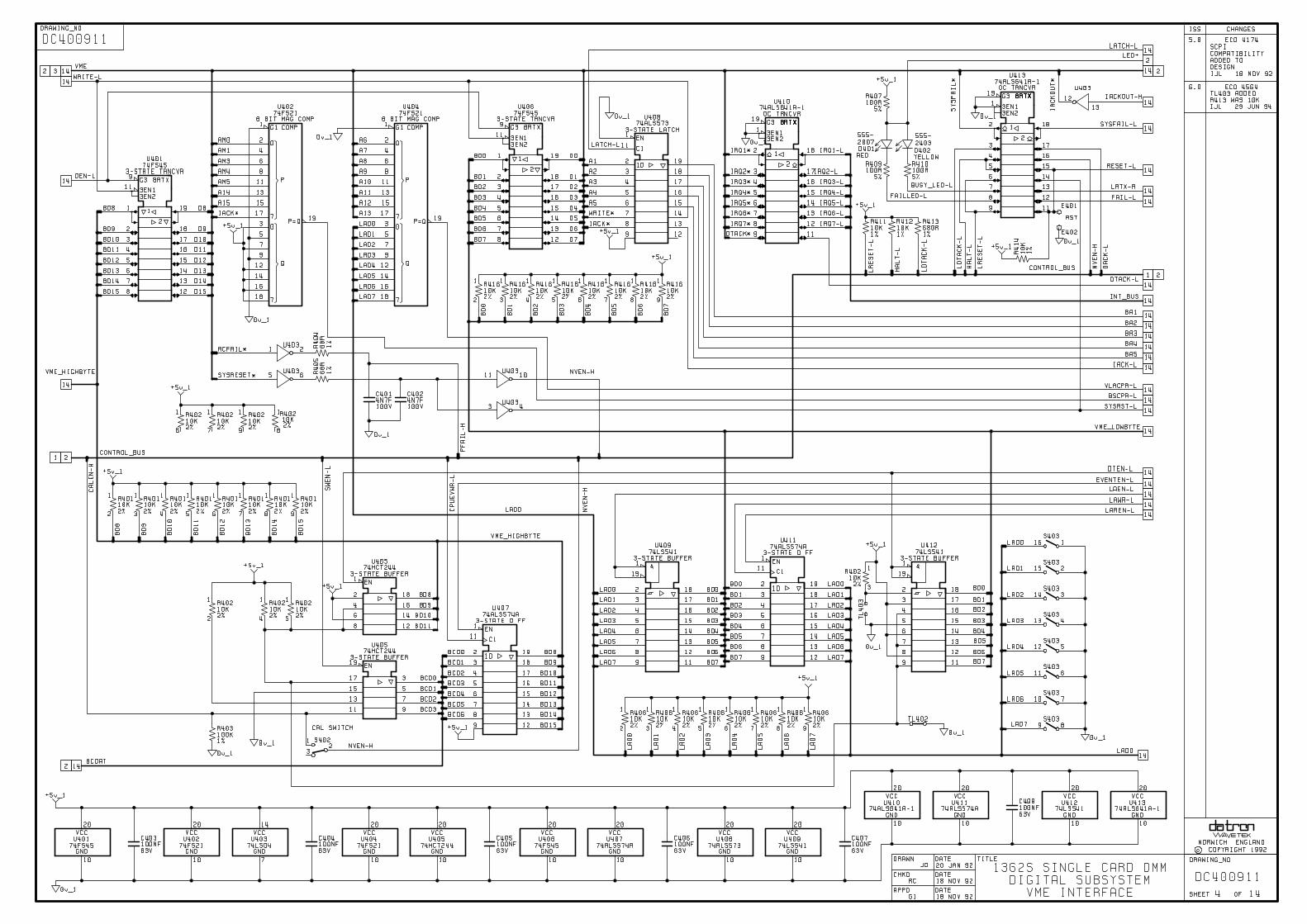

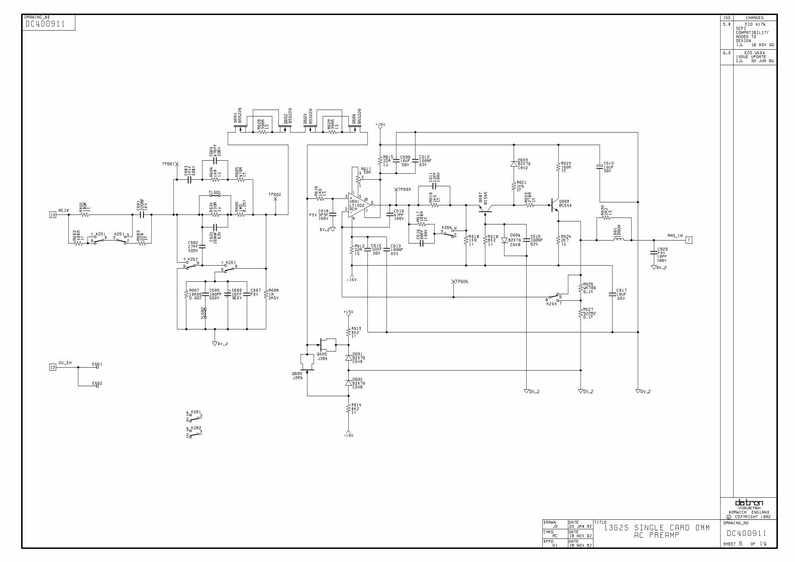
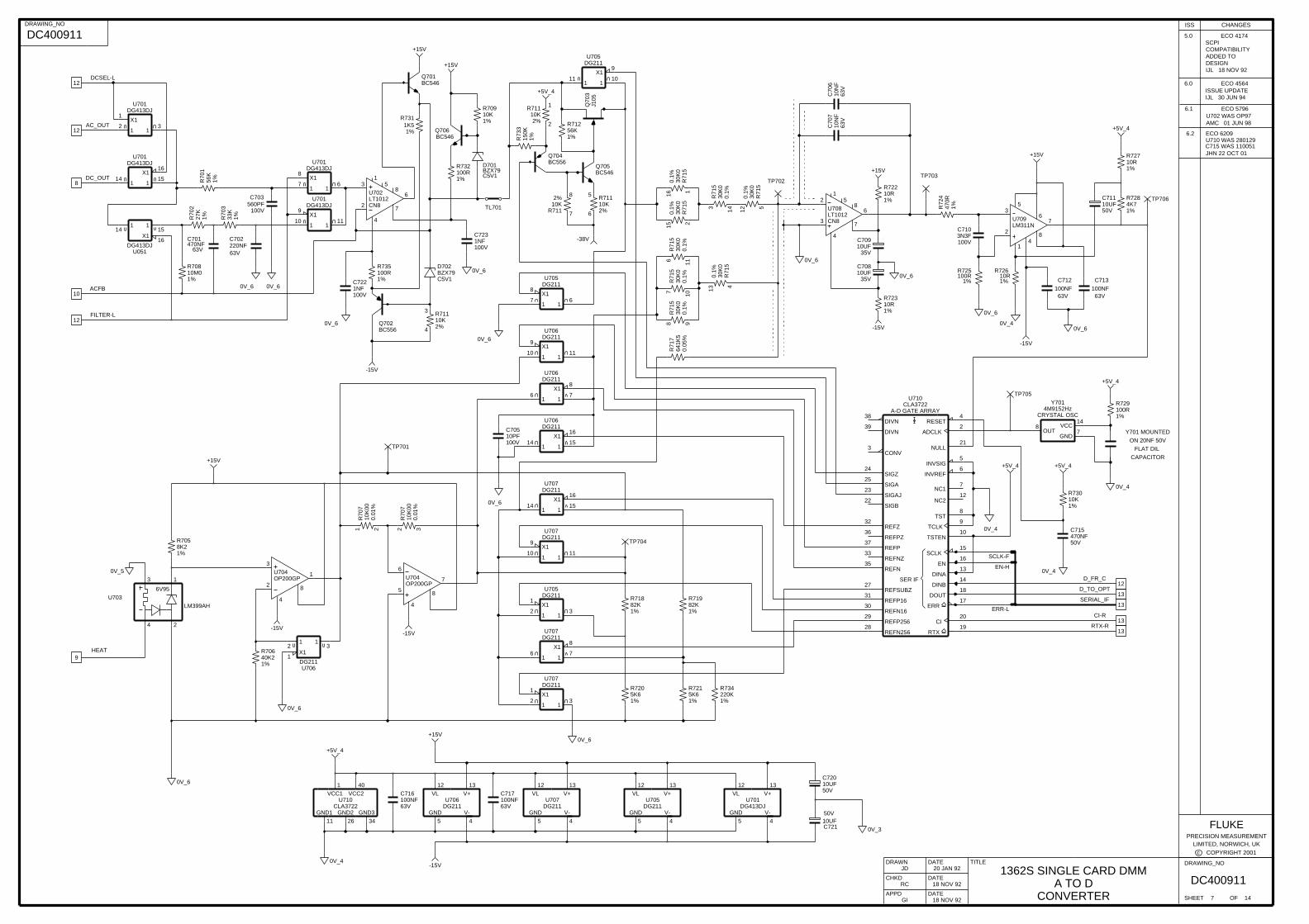
AMC 01 JUN 98
Y701 MOUNTED
ON 20NF 50V
FLAT DIL
CAPACITOR
ADDED TODESIGNIJL 18 NOV 92
0V_6
10UF35V
C709
6.0 ECO 4564ISSUE UPDATEIJL 30 JUN 94
6.2 ECO 6209U710 WAS 280129C715 WAS 110051JHN 22 OCT 01
5.0 ECO 4174SCPICOMPATIBILITY
6.1 ECO 5796U702 WAS OP97
4
3
-15V
+5V_4
TP70627
K1%R
702
C702
+5V_4
560PF100V
C703
R71110K2%
10N
F63
V
10UF35V
C708
+5V_4
+15V
220NF63V
6INVREF
5INVSIG
4RESET
15SCLK
-38V
0V_6
TL701
C70
7
19RTX
25SIGA
23SIGAJ
22SIGB
24SIGZ
9TCLK
8TST
10TSTEN
3CONV
38DIVN
17ERR
NULL
35REFN
30REFN16
28REFN256
33REFNZ
37REFP
31REFP16
29REFP256
36REFPZ
27REFSUBZ
32REFZ
SER IF
2ADCLK
20CI
13DINA
14DINB
39DIVN
18DOUT
16EN
7NC1
12NC2
21
C71110UF50V
R7284K71%
U710
A-D GATE ARRAYCLA3722
c COPYRIGHT 2001LIMITED, NORWICH, UK
ISS CHANGES
0V_6
1%5K6R720
470NF50V
C715
U705
17
X18
16
R71982K1%
0V_6
FLUKEPRECISION MEASUREMENT
+15V
U705DG211
21
1X1
31
DG211
R72610R1%
C5V1BZX79D701
Q706BC546
BC546
DG211U707
5
GND
13
V+
4
V-
12
VL
U707
115
X116
114
R72210R1%
0V_6
Q701
98
100NF63V
C716
R735100R1%
DG211
17
X18
16
1NF100V
C722
30K
00.
1%
R71
5
1%100RR732
0V_6
30K
00.
1%
R71
5
116
DG211U707
DG211
101
9X1
111
30K
00.
1%
R71
5
13 4
21
1X1
31
30K
00.
1%
R71
5
15 2
0V_4
0V_6
U706
TP704
TP702
+5V_4
U706DG211
100V10PFC705
9
0V_6
63V470NFC701
-15V
R71110K2% 2
1
TP7038X1
61
+5V_4 63V
10N
FC
706
50V10UFC721
101
9X1
111
C710
100V3N3F
U701DG413DJ
71
141
U710CLA3722
GND1
11
GND2
26
GND3
34
VCC1
1
VCC2
40
U701DG413DJ
U705
110
X19
111
U701DG413DJ
151
16X1
U701DG413DJ
21
1X1
31
R721
1%5K6
DG211
DRAWING_NO
SHEET OF
DRAWN
CHKD
APPD
DATE
DATE
DATE
TITLE
18 NOV 92
18 NOV 92
RC
GI
DC4009117 14
1362S SINGLE CARD DMMA TO D
CONVERTER
20 JAN 92JD
DRAWING_NO
DC400911
1%100RR725
Q70
3J1
05
C713
100NF63V
-15V
13
R70
7
0.01
%10
K00
2 3
13
12
12
+15V
+15V
U709LM311N
1
2
3
4
5
67
8
61
+5V_4
C72010UF50V
0V_6
Q704BC556
0V_4
30K
00.
1%
R71
5
12 5
U706DG211
71
8X1
141
30K
00.
1%
R71
5
143
1%220KR734
0V_4
OP200GP
6
7
4
85
U706DG211
151
16X1
GND
5
V+
13
V-
4
VL
12
30K
00.
1%
R71
5
16 1
+15V
0V_4
U704
Y7014M9152Hz
CRYSTAL OSC
GND7OUT
8 VCC14
TP701
U706DG211
8K21%
R705
0V_4
0V_6
R73
3
1%150K
0V_3
R711
8
7
10
R71
7
0.05
%64
1K5
0V_6
13
126V95
LM399AH
1
2
3
4
56K
1%R70
12%
10K
-15V
1%33K
R70
3
R71110K2%6
5
U703
R70
7
0.01
%10
K00
21
U701DG413DJ
GND
5
V+
13
V-
4
VL
12
-15V
TP705
63V100NF
C712
13
12
8
-15V
R70810M01%
R709
1%10K
40K21%
R706
0V_6
Q702BC556
GND
5
V+
13
V-
4
VL
12
+15V
R72
447
0R1%
Q705BC546
1%10RR727
C5V1BZX79D702
U705DG211
1
13
1%10RR723
0V_5
R731
1%1K5
1
2
3
4
5
6
7
8
0V_6
DG211U707
12
X1
2
1
4
8
3
100NF63V
C717
LT1012CN8
U702
107
DG211U707
110
X19
111
U704OP200GP
U708
12
3
4
5
6
7
8
30K
00.
1%
R71
5
R73010K1%
1NF100V
C723
LT1012CN8
DG413DJ
151
16X1
141
1%82KR718
R712
1%56K
ACFB
D_FR_C
D_TO_OPT
SCLK-F
EN-H
ERR-L
RTX-R
CI-R
SERIAL_IF
HEAT
AC_OUT
DCSEL-L
DC_OUT
FILTER-L
R729100R1%
U051
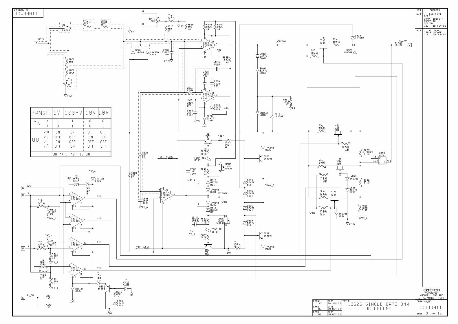

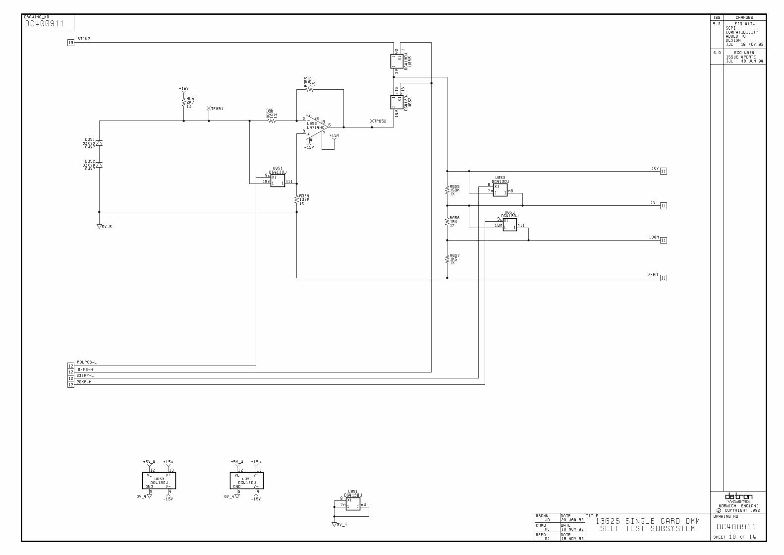

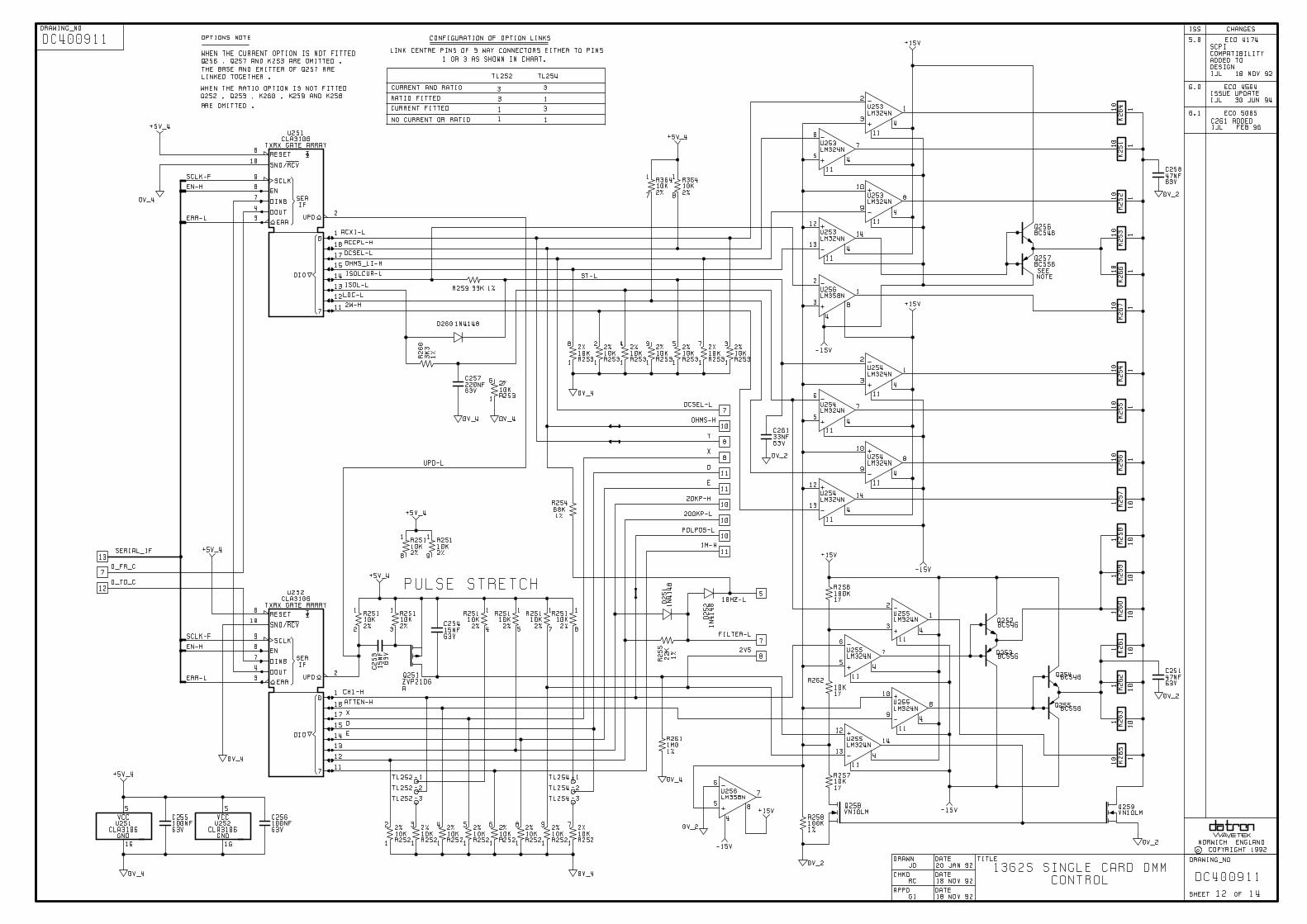
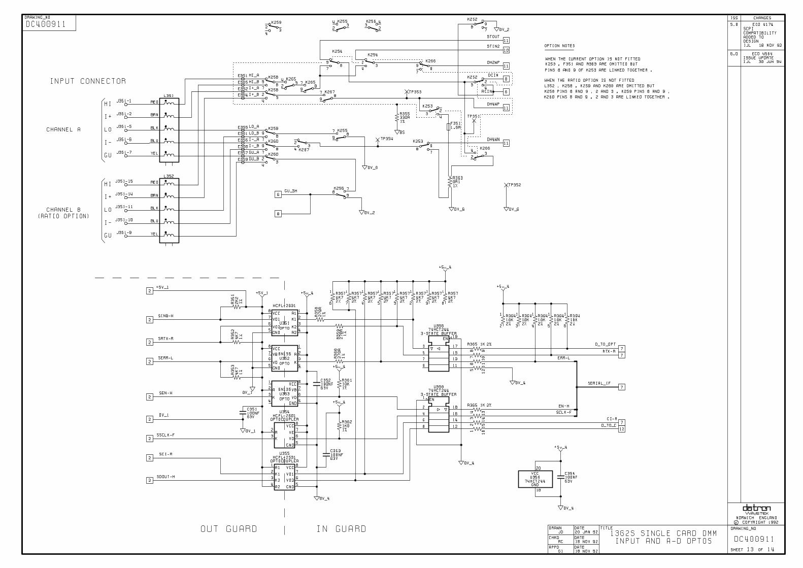
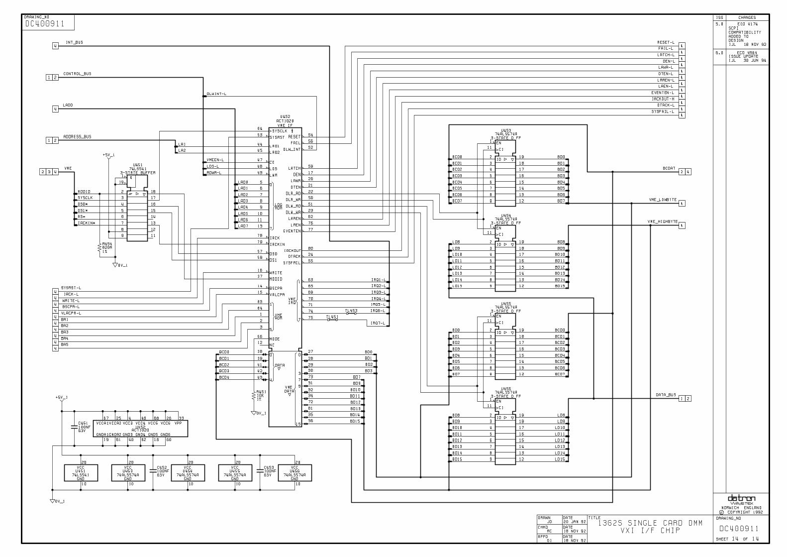

Section 12 - Component Lists
12-1
Contents
N.B. 1. Servicing Diagrams appear in Section 11.2. The pages in this section are not numbered, but the Parts Lists are placed in the following order.
SECTION 12 1362 Component Lists
Assembly Description Part No.
1362 Finished Instrument Parts List ..........................1362S Finished Instrument Parts List .......................1362MT Finished Instrument Parts List .....................
Card DMM Assembly Parts List ................................
LP400910LP401080LP400952
LP400911

FLUKE PM PARTS LIST 03-Oct-2002 DESC: ASSY FINISHED INST 1362 DRG NO: LP400910-2 REV: 11 PAGE: 1 OF 1======== ========== =========== ============================================== ========================= ======= ==============
DESIG PART NUMBER DESCRIPTION PRINCIPAL MANUF MANUF PART NUMBER CLASS UM QUANTITY====== =============== ======================================== ==================== ==================== ===== === ========U101 280191 IC DIG PROCESSOR 16 BIT 8MHz PHILIPS SCN68000CBA68 AO EA 1U102 400919-3 ASSY EPROM 1362 FLUKE SEE DRG S2 1U103 400919-3 ASSY EPROM 1362 FLUKE SEE DRG S2 -U107 401083-1 ASSY FPLD ADDR DECODE 1362S FLUKE SEE DRG EA 1U452 400914-4 ASSY FPGA VXI INT 1362 FLUKE SEE DRG EA 1
#1 400911-6 ASSY PCB VXI CARD DMM 1362 BI ELECTRONICS SEE DRG EA 1#1 400912-1 ASSY CABLE SINGLE I/P 1505 FLUKE SEE DRG EA 0#1 400953-1 ASSY CABLE RATIO I/P 1506 FLUKE SEE DRG EA 0#1 410441-5 PCB TOP SCREEN 1362 INLYNE SEE DRG EA 1#1 410442-1 PCB BOTTOM SCREEN 1362 INLYNE SEE DRG EA 1
#1 420074-1 LABEL MOD RECORD 1281 RS COMPONENTS 606-226 EA 1#1 420114 LABEL SSD WARNING DESTRUCTABLE 3M 7102 A EA 1#1 420119-1 LABEL CAL STICKER CJM LABELS SEE DRG EA 2#1 420120 LABEL SSD WARNING DESTRUCTABLE STATIC SAFE ENVIRONM SWL 1939 EA 2#1 420143-2 LABEL CARTON 148.5 X 50 CROWE SEE DRG EA 1
#1 420146 LABEL 63.5 X 25.4 SILVER/PE BRADY LAT-21-773-1 EA 1#1 440164-1 KIT CURRENT OPTION 1362 FLUKE SEE DRG EA 0#1 440165-1 KIT RATIO OPTION 1362 FLUKE SEE DRG EA 0#1 450778-3 TOP COVER 1361 FARNELL TECH SEE DRG EA 1#1 450779-2 BOTTOM COVER 1362 FARNELL TECH SEE DRG EA 1
#1 450785-3 PANEL FRONT 1362 FARNELL TECH SEE DRG EA 1#1 450787-2 PACKING BOX 1362 A.E.SUTTON SEE DRG EA 1#1 450788-1 INSULATION SHEET 1362 KENSULAT SEE DRG EA 1#1 450789-3 EARTHING SHIELD PSU 1362 FARNELL TECH SEE DRG EA 1#1 450790-3 GUARD SHIELD PSU 1362 FARNELL TECH SEE DRG EA 1
#1 450791-3 GUARD SHIELD AC 1361 FARNELL TECH SEE DRG EA 1#1 450819-1 COVER INSULATION 1362 HUGHES & WYNNE SEE DRG EA 1#1 450965-3 OVERLAY 1362 TRIMCRAFT SEE DRG EA 1#1 450971-1 NAMEPLATE ’WAVETEK’ 1362 SCREENCRAFT SEE DRG EA 1#1 450972-1 NAMEPLATE ’VXI’ 1362 SCREENCRAFT SEE DRG EA 1
#1 451395-1 INSULATOR A-D FPGA 1362 HUGHES & WYNNE SEE DRG EA 1#1 590077 SLEEVE HS 0.125 DIA CLEAR RAYCHEM KYNAR 1/8x1.2m CLEAR AR 1#1 604110 PLUG 15-WAY D TYPE CANNON DAM-15P A EA 1#1 605206 SOCKET 15-WAY D TYPE CANNON DAM-15S EA 1#1 606003 WASHER 1/2" WAVY PYE CONNECTORS MLW EA 1
#1 606028 SCREW LOCK D TYPE CANNON D20418-2 EA 2#1 606036 CABLE MOUNT MET JUNC SHELL 3M 3357-9215 EA 1#1 611023 SCREW M2.5 X 10 POZIPAN SZP GKN SEE DRG DP611000 EA 2#1 611114 SCREW M2.5 X 11 COLLAR SCHROFF 21100-379 EA 2#1 611117 SCREW M2.5 X 8 POZICSK SZP GKN SEE DRG DP611000 EA 2
#1 611120 SCREW M3 X 6 POZICSK SS GKN SEE DRG DP611000 EA 6#1 611121 SCREW M3 X 6 POZIPAN SS GKN SEE DRG DP611000 EA 4#1 612056-2 STANDOFF M3 X 2.5 SWIFT ENGINEERING SEE DRG EA 6#1 612057 SPACER M3 X 14 M/F HEX HARWIN R30-3001402 EA 6#1 613029 WASHER M3 CRINKLE SS GKN SEE DRG DP611000 P EA 10
#1 613047 WASHER M2.5 CRINKLE SS GKN SEE DRG DP611000 P EA 2#1 615027 NUT SPECIAL BNC 1/2"-28 HEX AMP 1-329631-2 EA 1#1 617019 SLEEVE SCREW RETAINING GREY SCHROFF 21100-464 EA 2#1 618016 PAD INSUL SIL TO220 SELF ADH WARTH K177-AC-819 EA 2#1 630255 TAPE SELF ADH DBL SIDED 3M Y9469 X 1/2" WIDE AR 1
#1 630355 CLIP CABLE SUPPORT LEWIS SPRING L.S.108/65 EA 2#1 630359 EJECTOR HANDLE TOP SCHROFF 20817-328 EA 1#1 630360 EJECTOR HANDLE BOTTOM SCHROFF 20817-327 EA 1#1 630373-1 SILICA GEL SELF-IND 50G GEEJAY CHEMICALS SEE DRG EA 1#1 630476 BAG ANTI STATIC CUSHIONED 40 X 3M 2120/16 X 11 EA 1
#1 850255-4 HANDBOOK USERS 1362 CROWE SEE DRG EA 1#1 900009 LOCKING COMPOUND LOCTITE 222 AR 1

FLUKE PM PARTS LIST 03-Oct-2002 DESC: ASSY FINISHED INST 1362S DRG NO: LP401080-2 REV: 9 PAGE: 1 OF 1======== ========== =========== ============================================== ========================= ======= ==============
DESIG PART NUMBER DESCRIPTION PRINCIPAL MANUF MANUF PART NUMBER CLASS UM QUANTITY====== =============== ======================================== ==================== ==================== ===== === ========U101 280220 IC DIG PROCESSOR 16 BIT 16MHz MOTOROLA MC68HC001FN16 EA 1U102 401082-5 ASSY EPROM 1362S FLUKE SEE DRG S2 1U103 401082-5 ASSY EPROM 1362S FLUKE SEE DRG S2 -U107 401197-1 ASSY FPLD ADDR DECODE VX4237 FLUKE SEE DRG EA 1U452 400914-4 ASSY FPGA VXI INT 1362 FLUKE SEE DRG EA 1
#1 400911-6 ASSY PCB VXI CARD DMM 1362 BI ELECTRONICS SEE DRG EA 1#1 400912-1 ASSY CABLE SINGLE I/P 1505 FLUKE SEE DRG EA 0#1 400953-1 ASSY CABLE RATIO I/P 1506 FLUKE SEE DRG EA 0#1 401328-2 ASSY DISK VXI P&P DRIVER 1362 FLUKE SEE DRG EA 1#1 410441-5 PCB TOP SCREEN 1362 INLYNE SEE DRG EA 1
#1 410442-1 PCB BOTTOM SCREEN 1362 INLYNE SEE DRG EA 1#1 420114 LABEL SSD WARNING DESTRUCTABLE 3M 7102 A EA 1#1 420119-1 LABEL CAL STICKER CJM LABELS SEE DRG EA 2#1 420120 LABEL SSD WARNING DESTRUCTABLE STATIC SAFE ENVIRONM SWL 1939 EA 2#1 420143-2 LABEL CARTON 148.5 X 50 CROWE SEE DRG EA 1
#1 420146 LABEL 63.5 X 25.4 SILVER/PE BRADY LAT-21-773-1 EA 1#1 440164-1 KIT CURRENT OPTION 1362 FLUKE SEE DRG EA 0#1 440165-1 KIT RATIO OPTION 1362 FLUKE SEE DRG EA 0#1 450778-3 TOP COVER 1361 FARNELL TECH SEE DRG EA 1#1 450779-2 BOTTOM COVER 1362 FARNELL TECH SEE DRG EA 1
#1 450785-3 PANEL FRONT 1362 FARNELL TECH SEE DRG EA 1#1 450787-2 PACKING BOX 1362 A.E.SUTTON SEE DRG EA 1#1 450788-1 INSULATION SHEET 1362 KENSULAT SEE DRG EA 1#1 450789-3 EARTHING SHIELD PSU 1362 FARNELL TECH SEE DRG EA 1#1 450790-3 GUARD SHIELD PSU 1362 FARNELL TECH SEE DRG EA 1
#1 450791-3 GUARD SHIELD AC 1361 FARNELL TECH SEE DRG EA 1#1 450819-1 COVER INSULATION 1362 HUGHES & WYNNE SEE DRG EA 1#1 450965-3 OVERLAY 1362 TRIMCRAFT SEE DRG EA 1#1 450971-1 NAMEPLATE ’WAVETEK’ 1362 SCREENCRAFT SEE DRG EA 1#1 450972-1 NAMEPLATE ’VXI’ 1362 SCREENCRAFT SEE DRG EA 1
#1 451395-1 INSULATOR A-D FPGA 1362 HUGHES & WYNNE SEE DRG EA 1#1 590077 SLEEVE HS 0.125 DIA CLEAR RAYCHEM KYNAR 1/8x1.2m CLEAR AR 1#1 604110 PLUG 15-WAY D TYPE CANNON DAM-15P A EA 1#1 605206 SOCKET 15-WAY D TYPE CANNON DAM-15S EA 1#1 606003 WASHER 1/2" WAVY PYE CONNECTORS MLW EA 1
#1 606028 SCREW LOCK D TYPE CANNON D20418-2 EA 2#1 606036 CABLE MOUNT MET JUNC SHELL 3M 3357-9215 EA 1#1 611023 SCREW M2.5 X 10 POZIPAN SZP GKN SEE DRG DP611000 EA 2#1 611114 SCREW M2.5 X 11 COLLAR SCHROFF 21100-379 EA 2#1 611117 SCREW M2.5 X 8 POZICSK SZP GKN SEE DRG DP611000 EA 2
#1 611120 SCREW M3 X 6 POZICSK SS GKN SEE DRG DP611000 EA 6#1 611121 SCREW M3 X 6 POZIPAN SS GKN SEE DRG DP611000 EA 4#1 612056-2 STANDOFF M3 X 2.5 SWIFT ENGINEERING SEE DRG EA 6#1 612057 SPACER M3 X 14 M/F HEX HARWIN R30-3001402 EA 6#1 613029 WASHER M3 CRINKLE SS GKN SEE DRG DP611000 P EA 10
#1 613047 WASHER M2.5 CRINKLE SS GKN SEE DRG DP611000 P EA 2#1 615027 NUT SPECIAL BNC 1/2"-28 HEX AMP 1-329631-2 EA 1#1 617019 SLEEVE SCREW RETAINING GREY SCHROFF 21100-464 EA 2#1 618016 PAD INSUL SIL TO220 SELF ADH WARTH K177-AC-819 EA 2#1 630255 TAPE SELF ADH DBL SIDED 3M Y9469 X 1/2" WIDE AR 1
#1 630355 CLIP CABLE SUPPORT LEWIS SPRING L.S.108/65 EA 2#1 630359 EJECTOR HANDLE TOP SCHROFF 20817-328 EA 1#1 630360 EJECTOR HANDLE BOTTOM SCHROFF 20817-327 EA 1#1 630373-1 SILICA GEL SELF-IND 50G GEEJAY CHEMICALS SEE DRG EA 1#1 630476 BAG ANTI STATIC CUSHIONED 40 X 3M 2120/16 X 11 EA 1
#1 850255-4 HANDBOOK USERS 1362 CROWE SEE DRG EA 1#1 900009 LOCKING COMPOUND LOCTITE 222 AR 1
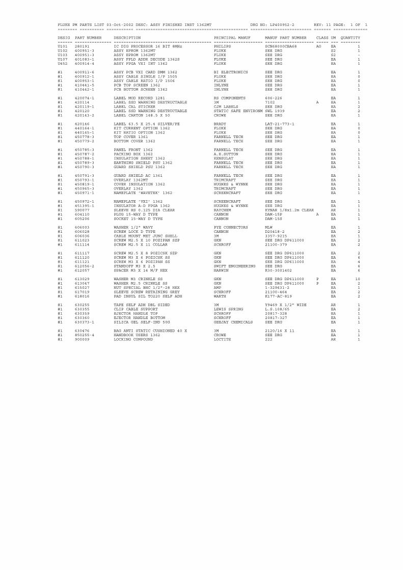
FLUKE PM PARTS LIST 03-Oct-2002 DESC: ASSY FINISHED INST 1362MT DRG NO: LP400952-2 REV: 11 PAGE: 1 OF 1======== ========== =========== ============================================== ========================= ======= ==============
DESIG PART NUMBER DESCRIPTION PRINCIPAL MANUF MANUF PART NUMBER CLASS UM QUANTITY====== =============== ======================================== ==================== ==================== ===== === ========U101 280191 IC DIG PROCESSOR 16 BIT 8MHz PHILIPS SCN68000CBA68 AO EA 1U102 400951-3 ASSY EPROM 1362MT FLUKE SEE DRG S2 1U103 400951-3 ASSY EPROM 1362MT FLUKE SEE DRG S2 -U107 401083-1 ASSY FPLD ADDR DECODE 1362S FLUKE SEE DRG EA 1U452 400914-4 ASSY FPGA VXI INT 1362 FLUKE SEE DRG EA 1
#1 400911-6 ASSY PCB VXI CARD DMM 1362 BI ELECTRONICS SEE DRG EA 1#1 400912-1 ASSY CABLE SINGLE I/P 1505 FLUKE SEE DRG EA 0#1 400953-1 ASSY CABLE RATIO I/P 1506 FLUKE SEE DRG EA 0#1 410441-5 PCB TOP SCREEN 1362 INLYNE SEE DRG EA 1#1 410442-1 PCB BOTTOM SCREEN 1362 INLYNE SEE DRG EA 1
#1 420074-1 LABEL MOD RECORD 1281 RS COMPONENTS 606-226 EA 1#1 420114 LABEL SSD WARNING DESTRUCTABLE 3M 7102 A EA 1#1 420119-1 LABEL CAL STICKER CJM LABELS SEE DRG EA 2#1 420120 LABEL SSD WARNING DESTRUCTABLE STATIC SAFE ENVIRONM SWL 1939 EA 2#1 420143-2 LABEL CARTON 148.5 X 50 CROWE SEE DRG EA 1
#1 420146 LABEL 63.5 X 25.4 SILVER/PE BRADY LAT-21-773-1 EA 1#1 440164-1 KIT CURRENT OPTION 1362 FLUKE SEE DRG EA 0#1 440165-1 KIT RATIO OPTION 1362 FLUKE SEE DRG EA 0#1 450778-3 TOP COVER 1361 FARNELL TECH SEE DRG EA 1#1 450779-2 BOTTOM COVER 1362 FARNELL TECH SEE DRG EA 1
#1 450785-3 PANEL FRONT 1362 FARNELL TECH SEE DRG EA 1#1 450787-2 PACKING BOX 1362 A.E.SUTTON SEE DRG EA 1#1 450788-1 INSULATION SHEET 1362 KENSULAT SEE DRG EA 1#1 450789-3 EARTHING SHIELD PSU 1362 FARNELL TECH SEE DRG EA 1#1 450790-3 GUARD SHIELD PSU 1362 FARNELL TECH SEE DRG EA 1
#1 450791-3 GUARD SHIELD AC 1361 FARNELL TECH SEE DRG EA 1#1 450793-1 OVERLAY 1362MT TRIMCRAFT SEE DRG EA 1#1 450819-1 COVER INSULATION 1362 HUGHES & WYNNE SEE DRG EA 1#1 450965-3 OVERLAY 1362 TRIMCRAFT SEE DRG EA 1#1 450971-1 NAMEPLATE ’WAVETEK’ 1362 SCREENCRAFT SEE DRG EA 1
#1 450972-1 NAMEPLATE ’VXI’ 1362 SCREENCRAFT SEE DRG EA 1#1 451395-1 INSULATOR A-D FPGA 1362 HUGHES & WYNNE SEE DRG EA 1#1 590077 SLEEVE HS 0.125 DIA CLEAR RAYCHEM KYNAR 1/8x1.2m CLEAR AR 1#1 604110 PLUG 15-WAY D TYPE CANNON DAM-15P A EA 1#1 605206 SOCKET 15-WAY D TYPE CANNON DAM-15S EA 1
#1 606003 WASHER 1/2" WAVY PYE CONNECTORS MLW EA 1#1 606028 SCREW LOCK D TYPE CANNON D20418-2 EA 2#1 606036 CABLE MOUNT MET JUNC SHELL 3M 3357-9215 EA 1#1 611023 SCREW M2.5 X 10 POZIPAN SZP GKN SEE DRG DP611000 EA 2#1 611114 SCREW M2.5 X 11 COLLAR SCHROFF 21100-379 EA 2
#1 611117 SCREW M2.5 X 8 POZICSK SZP GKN SEE DRG DP611000 EA 2#1 611120 SCREW M3 X 6 POZICSK SS GKN SEE DRG DP611000 EA 6#1 611121 SCREW M3 X 6 POZIPAN SS GKN SEE DRG DP611000 EA 4#1 612056-2 STANDOFF M3 X 2.5 SWIFT ENGINEERING SEE DRG EA 6#1 612057 SPACER M3 X 14 M/F HEX HARWIN R30-3001402 EA 6
#1 613029 WASHER M3 CRINKLE SS GKN SEE DRG DP611000 P EA 10#1 613047 WASHER M2.5 CRINKLE SS GKN SEE DRG DP611000 P EA 2#1 615027 NUT SPECIAL BNC 1/2"-28 HEX AMP 1-329631-2 EA 1#1 617019 SLEEVE SCREW RETAINING GREY SCHROFF 21100-464 EA 2#1 618016 PAD INSUL SIL TO220 SELF ADH WARTH K177-AC-819 EA 2
#1 630255 TAPE SELF ADH DBL SIDED 3M Y9469 X 1/2" WIDE AR 1#1 630355 CLIP CABLE SUPPORT LEWIS SPRING L.S.108/65 EA 2#1 630359 EJECTOR HANDLE TOP SCHROFF 20817-328 EA 1#1 630360 EJECTOR HANDLE BOTTOM SCHROFF 20817-327 EA 1#1 630373-1 SILICA GEL SELF-IND 50G GEEJAY CHEMICALS SEE DRG EA 1
#1 630476 BAG ANTI STATIC CUSHIONED 40 X 3M 2120/16 X 11 EA 1#1 850255-4 HANDBOOK USERS 1362 CROWE SEE DRG EA 1#1 900009 LOCKING COMPOUND LOCTITE 222 AR 1

FLUKE PM PARTS LIST 03-Oct-2002 DESC: ASSY PCB VXI CARD DMM 1362 DRG NO: LP400911-6 REV: 13 PAGE: 1 OF 8======== ========== =========== ============================================== ========================= ======= ==============
DESIG PART NUMBER DESCRIPTION PRINCIPAL MANUF MANUF PART NUMBER CLASS UM QUANTITY====== =============== ======================================== ==================== ==================== ===== === ========R051 050117 RES MF 2k7 1% .12W 100PPM NEOHM LR0204 2K7 1% A EA 6R052 050136 RES MF 100k 1% .12W 100PPM NEOHM LR0204 100K 1% A EA 6R053 050136 RES MF 100k 1% .12W 100PPM NEOHM LR0204 100K 1% A EA -R054 050136 RES MF 100k 1% .12W 100PPM NEOHM LR0204 100K 1% A EA -R055 050138 RES MF 150k 1% .12W 100PPM NEOHM LR0204 150K 1% EA 2
R056 050126 RES MF 15k 1% .12W 100PPM NEOHM LR0204 15K 1% A EA 4R057 050114 RES MF 1k5 1% .12W 100PPM NEOHM LR0204 1K5 1% A EA 8R101 050124 RES MF 10k 1% .12W 100PPM NEOHM LR0204 10K 1% A EA 21R102 090163 RES NTWK 10k X 8 2% BECKMAN L09-1S-103 A EA 8R103 050124 RES MF 10k 1% .12W 100PPM NEOHM LR0204 10K 1% A EA -
R104 050095 RES MF 39R 1% .12W 100PPM NEOHM LR0204 39R 1% A EA 1R150 050112 RES MF 1k0 1% .12W 100PPM NEOHM LR0204 1K0 1% A EA 8R153 050124 RES MF 10k 1% .12W 100PPM NEOHM LR0204 10K 1% A EA -R154 050128 RES MF 22k 1% .12W 100PPM NEOHM LR0204 22K 1% A EA 6R155 050128 RES MF 22k 1% .12W 100PPM NEOHM LR0204 22K 1% A EA -
R156 080122 RES FL 7k 0.05% 3PPM VISHAY VH202L 7K0000 0.05% EA 1R157 080153 RES FL 63k 0.05% 3PPM VISHAY VH202L 63K000 0.05% EA 1R158 050121 RES MF 5k6 1% .12W 100PPM NEOHM LR0204 5K6 1% A EA 3R159 090194-1 RES WW SET 495k/3k/2k 0.2%R VISHAY PC350/175 TO DRG S3 1R160 090194-1 RES WW SET 495k/3k/2k 0.2%R VISHAY PC350/175 TO DRG S3 -
R161 090194-1 RES WW SET 495k/3k/2k 0.2%R VISHAY PC350/175 TO DRG S3 -R162 050128 RES MF 22k 1% .12W 100PPM NEOHM LR0204 22K 1% A EA -R163 090182 THERMISTOR PTC 1k 40% 1kV MIDWEST 180Q10215 EA 1R164 090001 THERMISTOR PTC 80R PHILIPS VA8650 EA 1R165 050119 RES MF 3k9 1% .12W 100PPM NEOHM LR0204 3K9 1% A EA 1
R201 050124 RES MF 10k 1% .12W 100PPM NEOHM LR0204 10K 1% A EA -R202 050124 RES MF 10k 1% .12W 100PPM NEOHM LR0204 10K 1% A EA -R203 050124 RES MF 10k 1% .12W 100PPM NEOHM LR0204 10K 1% A EA -R204 050124 RES MF 10k 1% .12W 100PPM NEOHM LR0204 10K 1% A EA -R205 050124 RES MF 10k 1% .12W 100PPM NEOHM LR0204 10K 1% A EA -
R206 090165 RES PACK 68R X 4 2% BECKMAN L08-3S-680 A EA 2R207 090165 RES PACK 68R X 4 2% BECKMAN L08-3S-680 A EA -R208 090041 RES NTWK 4k7 X 7 2% BECKMAN L08-1S-472 A EA 1R209 090162 RES PACK 270R X 4 2% AB 770-83-270R A EA 1R210 050110 RES MF 680R 1% .12W 100PPM NEOHM LR0204 680R 1% A EA 4
R211 050124 RES MF 10k 1% .12W 100PPM NEOHM LR0204 10K 1% A EA -R213 050100 RES MF 100R 1% .12W 100PPM NEOHM LR0204 100R 1% A EA 10R214 012211 RES MF 2k21 1% .12W 50PPM MEC H8 2K21 1% 50PPM AP EA 1R251 090163 RES NTWK 10k X 8 2% BECKMAN L09-1S-103 A EA -R252 090163 RES NTWK 10k X 8 2% BECKMAN L09-1S-103 A EA -
R253 090163 RES NTWK 10k X 8 2% BECKMAN L09-1S-103 A EA -R254 050134 RES MF 68k 1% .12W 100PPM NEOHM LR0204 68K 1% A EA 6R255 050128 RES MF 22k 1% .12W 100PPM NEOHM LR0204 22K 1% A EA -R256 050136 RES MF 100k 1% .12W 100PPM NEOHM LR0204 100K 1% A EA -R257 050124 RES MF 10k 1% .12W 100PPM NEOHM LR0204 10K 1% A EA -
R258 050136 RES MF 100k 1% .12W 100PPM NEOHM LR0204 100K 1% A EA -R259 050130 RES MF 33k 1% .12W 100PPM NEOHM LR0204 33K 1% A EA 6R260 050118 RES MF 3k3 1% .12W 100PPM NEOHM LR0204 3K3 1% A EA 2R261 050148 RES MF 1M0 1% .12W 100PPM NEOHM LR0204 1M0 1% EA 2R262 050124 RES MF 10k 1% .12W 100PPM NEOHM LR0204 10K 1% A EA -
R301 050100 RES MF 100R 1% .12W 100PPM NEOHM LR0204 100R 1% A EA -R302 050100 RES MF 100R 1% .12W 100PPM NEOHM LR0204 100R 1% A EA -R303 050124 RES MF 10k 1% .12W 100PPM NEOHM LR0204 10K 1% A EA -R351 050116 RES MF 2k2 1% .12W 100PPM NEOHM LR0204 2K2 1% A EA 4R352 050120 RES MF 4k7 1% .12W 100PPM NEOHM LR0204 4K7 1% A EA 4
R353 050120 RES MF 4k7 1% .12W 100PPM NEOHM LR0204 4K7 1% A EA -R355 050106 RES MF 330R 1% .12W 100PPM NEOHM LR0204 330R 1% A EA 2R357 090179 RES NTWK 4k7 X 8 2% BECKMAN L09-1S-472 AP EA 1R358 050105 RES MF 270R 1% .12W 100PPM NEOHM LR0204 270R 1% A EA 4R359 050105 RES MF 270R 1% .12W 100PPM NEOHM LR0204 270R 1% A EA -
R360 050105 RES MF 270R 1% .12W 100PPM NEOHM LR0204 270R 1% A EA -R361 050124 RES MF 10k 1% .12W 100PPM NEOHM LR0204 10K 1% A EA -R362 050112 RES MF 1k0 1% .12W 100PPM NEOHM LR0204 1K0 1% A EA -R363 00000N NOT FITTED FLUKE 00000N EA 33R364 090046 RES NTWK 10k X 7 2% BECKMAN L08-1S-103 A EA 1
R365 090154 RES PACK 1k X 8 2% AB 761-3-1K A EA 1R401 090163 RES NTWK 10k X 8 2% BECKMAN L09-1S-103 A EA -R402 090163 RES NTWK 10k X 8 2% BECKMAN L09-1S-103 A EA -R403 050136 RES MF 100k 1% .12W 100PPM NEOHM LR0204 100K 1% A EA -R404 050098 RES MF 68R 1% .12W 100PPM NEOHM LR0204 68R 1% A EA 3
R405 050098 RES MF 68R 1% .12W 100PPM NEOHM LR0204 68R 1% A EA -R406 090163 RES NTWK 10k X 8 2% BECKMAN L09-1S-103 A EA -R407 000101 RES CF 100R 5% .25W NEOHM CFR25 100R 5% A EA 3R409 000101 RES CF 100R 5% .25W NEOHM CFR25 100R 5% A EA -R410 000101 RES CF 100R 5% .25W NEOHM CFR25 100R 5% A EA -
R411 050124 RES MF 10k 1% .12W 100PPM NEOHM LR0204 10K 1% A EA -R412 050124 RES MF 10k 1% .12W 100PPM NEOHM LR0204 10K 1% A EA -R413 050110 RES MF 680R 1% .12W 100PPM NEOHM LR0204 680R 1% A EA -R414 050124 RES MF 10k 1% .12W 100PPM NEOHM LR0204 10K 1% A EA -R416 090163 RES NTWK 10k X 8 2% BECKMAN L09-1S-103 A EA -
R451 050124 RES MF 10k 1% .12W 100PPM NEOHM LR0204 10K 1% A EA -R454 050111 RES MF 820R 1% .12W 100PPM NEOHM LR0204 820R 1% A EA 1R501 080106 RES FL 5k 0.01% 1PPM VISHAY S102K 5K0000 0.01% A EA 2R502 050130 RES MF 33k 1% .12W 100PPM NEOHM LR0204 33K 1% A EA -R503 050128 RES MF 22k 1% .12W 100PPM NEOHM LR0204 22K 1% A EA -
R504 050113 RES MF 1k2 1% .12W 100PPM NEOHM LR0204 1K2 1% A EA 2R505 050104 RES MF 220R 1% .12W 100PPM NEOHM LR0204 220R 1% A EA 5R506 050110 RES MF 680R 1% .12W 100PPM NEOHM LR0204 680R 1% A EA -R507 050098 RES MF 68R 1% .12W 100PPM NEOHM LR0204 68R 1% A EA -R508 050097 RES MF 56R 1% .12W 100PPM NEOHM LR0204 56R 1% A EA 1
R509 050123 RES MF 8k2 1% .12W 100PPM NEOHM LR0204 8K2 1% A EA 5R513 050120 RES MF 4k7 1% .12W 100PPM NEOHM LR0204 4K7 1% A EA -R514 050117 RES MF 2k7 1% .12W 100PPM NEOHM LR0204 2K7 1% A EA -R515 080106 RES FL 5k 0.01% 1PPM VISHAY S102K 5K0000 0.01% A EA -R516 050117 RES MF 2k7 1% .12W 100PPM NEOHM LR0204 2K7 1% A EA -
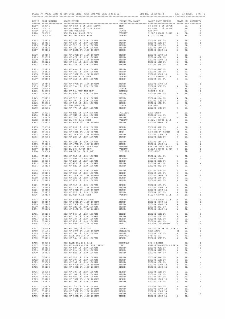
FLUKE PM PARTS LIST 03-Oct-2002 DESC: ASSY PCB VXI CARD DMM 1362 DRG NO: LP400911-6 REV: 13 PAGE: 2 OF 8======== ========== =========== ============================================== ========================= ======= ==============
DESIG PART NUMBER DESCRIPTION PRINCIPAL MANUF MANUF PART NUMBER CLASS UM QUANTITY====== =============== ======================================== ==================== ==================== ===== === ========R517 050076 RES MF 10k0 0.1% .12W 50PPM MEC H8 10K0 0.1% 50PPM EA 1R518 050077 RES MF 20k0 0.1% .12W 50PPM MEC H8 20K0 0.1% 50PPM EA 1R519 290026-3 KIT RMS SELECTED FLUKE SEE DRG S3 1R520 080082 RES FL 20k 0.01% 3PPM VISHAY S102C 20K000 0.01% A EA 1R521 080047-2 RES FL 10k 0.01% 3PPM VISHAY S102C TO DRG A EA 1
R523 050130 RES MF 33k 1% .12W 100PPM NEOHM LR0204 33K 1% A EA -R524 050125 RES MF 12k 1% .12W 100PPM NEOHM LR0204 12K 1% A EA 1R525 050114 RES MF 1k5 1% .12W 100PPM NEOHM LR0204 1K5 1% A EA -R526 050112 RES MF 1k0 1% .12W 100PPM NEOHM LR0204 1K0 1% A EA -R527 050104 RES MF 220R 1% .12W 100PPM NEOHM LR0204 220R 1% A EA -
R528 050100 RES MF 100R 1% .12W 100PPM NEOHM LR0204 100R 1% A EA -R529 050096 RES MF 47R 1% .12W 100PPM NEOHM LR0204 47R 1% A EA 2R530 050109 RES MF 560R 1% .12W 100PPM NEOHM LR0204 560R 1% A EA 1R531 050124 RES MF 10k 1% .12W 100PPM NEOHM LR0204 10K 1% A EA -R532 050130 RES MF 33k 1% .12W 100PPM NEOHM LR0204 33K 1% A EA -
R533 050134 RES MF 68k 1% .12W 100PPM NEOHM LR0204 68K 1% A EA -R534 050114 RES MF 1k5 1% .12W 100PPM NEOHM LR0204 1K5 1% A EA -R535 050106 RES MF 330R 1% .12W 100PPM NEOHM LR0204 330R 1% A EA -R536 080159 RES FL 40k 0.1% 3PPM VISHAY S102L 40K000 0.1% EA 2R537 050118 RES MF 3k3 1% .12W 100PPM NEOHM LR0204 3K3 1% A EA -
R538 050144 RES MF 470k 1% .12W 100PPM NEOHM LR0204 470K 1% EA 1R539 050130 RES MF 33k 1% .12W 100PPM NEOHM LR0204 33K 1% A EA -R540 00000F FSV FLUKE 00000F EA 1R541 065012 RES CT 50k TOP ADJ M/T BOURNS 3296W-1-503 EA 2R542 050134 RES MF 68k 1% .12W 100PPM NEOHM LR0204 68K 1% A EA -
R543 050112 RES MF 1k0 1% .12W 100PPM NEOHM LR0204 1K0 1% A EA -R544 050088 RES MF 10R 1% .12W 100PPM NEOHM LR0204 10R 1% A EA 8R545 050088 RES MF 10R 1% .12W 100PPM NEOHM LR0204 10R 1% A EA -R546 290026-3 KIT RMS SELECTED FLUKE SEE DRG S3 -R548 050096 RES MF 47R 1% .12W 100PPM NEOHM LR0204 47R 1% A EA -
R549 040825 RES MG 8M2 5% .25W 200PPM PHILIPS VR25-8M2-5 A EA 3R550 050148 RES MF 1M0 1% .12W 100PPM NEOHM LR0204 1M0 1% EA -R551 050113 RES MF 1k2 1% .12W 100PPM NEOHM LR0204 1K2 1% A EA -R552 080159 RES FL 40k 0.1% 3PPM VISHAY S102L 40K000 0.1% EA -R553 050110 RES MF 680R 1% .12W 100PPM NEOHM LR0204 680R 1% A EA -
R555 050099 RES MF 82R 1% .12W 100PPM NEOHM LR0204 82R 1% A EA 1R556 050128 RES MF 22k 1% .12W 100PPM NEOHM LR0204 22K 1% A EA -R601 011003 RES MF 100k 1% .12W 50PPM MEC H8 100K 1% 50PPM AP EA 1R602 050100 RES MF 100R 1% .12W 100PPM NEOHM LR0204 100R 1% A EA -R603 050092 RES MF 22R 1% .12W 100PPM NEOHM LR0204 22R 1% A EA 3
R604 050115 RES MF 1k8 1% .12W 100PPM NEOHM LR0204 1K8 1% A EA 1R605 050108 RES MF 470R 1% .12W 100PPM NEOHM LR0204 470R 1% A EA 4R606 050236-1 RES MF 1M 0.25% .25W 5PPM WELWYN MAR7T16 1M 0.25% A EA 1R607 080118 RES FL 10k 0.05% 3PPM VISHAY S102J 10K000 0.05% A EA 1R608 008004 RES MG 1M 5% .5W 2.5kV PHILIPS VR37-1M-5 EA 1
R610 050112 RES MF 1k0 1% .12W 100PPM NEOHM LR0204 1K0 1% A EA -R611 065012 RES CT 50k TOP ADJ M/T BOURNS 3296W-1-503 EA -R612 050092 RES MF 22R 1% .12W 100PPM NEOHM LR0204 22R 1% A EA -R613 050123 RES MF 8k2 1% .12W 100PPM NEOHM LR0204 8K2 1% A EA -R614 050123 RES MF 8k2 1% .12W 100PPM NEOHM LR0204 8K2 1% A EA -
R615 050092 RES MF 22R 1% .12W 100PPM NEOHM LR0204 22R 1% A EA -R616 050114 RES MF 1k5 1% .12W 100PPM NEOHM LR0204 1K5 1% A EA -R617 050103 RES MF 180R 1% .12W 100PPM NEOHM LR0204 180R 1% A EA 1R618 050112 RES MF 1k0 1% .12W 100PPM NEOHM LR0204 1K0 1% A EA -R619 050123 RES MF 8k2 1% .12W 100PPM NEOHM LR0204 8K2 1% A EA -
R621 050114 RES MF 1k5 1% .12W 100PPM NEOHM LR0204 1K5 1% A EA -R622 050105 RES MF 270R 1% .12W 100PPM NEOHM LR0204 270R 1% A EA -R623 050100 RES MF 100R 1% .12W 100PPM NEOHM LR0204 100R 1% A EA -R624 050117 RES MF 2k7 1% .12W 100PPM NEOHM LR0204 2K7 1% A EA -R626 080133 RES FL 4k7 0.1% 3PPM VISHAY S102J 4K7000 0.1% A EA 1
R627 080119 RES FL 522R2 0.1% 3PPM VISHAY S102J 522R20 0.1% A EA 1R628 050107 RES MF 390R 1% .12W 100PPM NEOHM LR0204 390R 1% A EA 2R629 050107 RES MF 390R 1% .12W 100PPM NEOHM LR0204 390R 1% A EA -R630 050116 RES MF 2k2 1% .12W 100PPM NEOHM LR0204 2K2 1% A EA -R631 050104 RES MF 220R 1% .12W 100PPM NEOHM LR0204 220R 1% A EA -
R701 050133 RES MF 56k 1% .12W 100PPM NEOHM LR0204 56K 1% A EA 3R702 050129 RES MF 27k 1% .12W 100PPM NEOHM LR0204 27K 1% A EA 1R703 050130 RES MF 33k 1% .12W 100PPM NEOHM LR0204 33K 1% A EA -R705 050123 RES MF 8k2 1% .12W 100PPM NEOHM LR0204 8K2 1% A EA -R706 014022 RES MF 40k2 1% .12W 50PPM MEC H8 40K2 1% 50PPM A EA 1
R707 090209 RES FL 10k/10k 0.01% VISHAY VHD144 2X10K 1A .01M A EA 1R708 041005 RES MF 10M0 1% .12W 100PPM STEATITE MK2010MFC AP EA 1R709 050124 RES MF 10k 1% .12W 100PPM NEOHM LR0204 10K 1% A EA -R711 090131 RES PACK 10k X 4 2% BECKMAN L08-3S-103 A EA 1R712 050133 RES MF 56k 1% .12W 100PPM NEOHM LR0204 56K 1% A EA -
R715 090214 RES PACK 30k X 8 0.1% BECKMAN 698-3-R30KB EA 1R717 050150 RES MF 641k5 0.05% .12W 15PPM IRC MAR6-T10-641K5-0.05% A EA 1R718 050135 RES MF 82k 1% .12W 100PPM NEOHM LR0204 82K 1% A EA 2R719 050135 RES MF 82k 1% .12W 100PPM NEOHM LR0204 82K 1% A EA -R720 050121 RES MF 5k6 1% .12W 100PPM NEOHM LR0204 5K6 1% A EA -
R721 050121 RES MF 5k6 1% .12W 100PPM NEOHM LR0204 5K6 1% A EA -R722 050088 RES MF 10R 1% .12W 100PPM NEOHM LR0204 10R 1% A EA -R723 050088 RES MF 10R 1% .12W 100PPM NEOHM LR0204 10R 1% A EA -R724 050108 RES MF 470R 1% .12W 100PPM NEOHM LR0204 470R 1% A EA -R725 050100 RES MF 100R 1% .12W 100PPM NEOHM LR0204 100R 1% A EA -
R726 050088 RES MF 10R 1% .12W 100PPM NEOHM LR0204 10R 1% A EA -R727 050088 RES MF 10R 1% .12W 100PPM NEOHM LR0204 10R 1% A EA -R728 050120 RES MF 4k7 1% .12W 100PPM NEOHM LR0204 4K7 1% A EA -R729 050100 RES MF 100R 1% .12W 100PPM NEOHM LR0204 100R 1% A EA -R730 050124 RES MF 10k 1% .12W 100PPM NEOHM LR0204 10K 1% A EA -
R731 050114 RES MF 1k5 1% .12W 100PPM NEOHM LR0204 1K5 1% A EA -R732 050100 RES MF 100R 1% .12W 100PPM NEOHM LR0204 100R 1% A EA -R733 050138 RES MF 150k 1% .12W 100PPM NEOHM LR0204 150K 1% EA -R734 050140 RES MF 220k 1% .12W 100PPM NEOHM LR0204 220K 1% EA 1R735 050100 RES MF 100R 1% .12W 100PPM NEOHM LR0204 100R 1% A EA -

FLUKE PM PARTS LIST 03-Oct-2002 DESC: ASSY PCB VXI CARD DMM 1362 DRG NO: LP400911-6 REV: 13 PAGE: 3 OF 8======== ========== =========== ============================================== ========================= ======= ==============
DESIG PART NUMBER DESCRIPTION PRINCIPAL MANUF MANUF PART NUMBER CLASS UM QUANTITY====== =============== ======================================== ==================== ==================== ===== === ========R801 002333 RES HM 33k 5% 1W ALLEN BRADLEY GB 33K 5% A EA 2R802 002333 RES HM 33k 5% 1W ALLEN BRADLEY GB 33K 5% A EA -R809 090180 RES NTWK 100k0/9M9 VISHAY 112VTF EA 1R810 090167 RES PACK 100k X 4 2% BECKMAN L08-3S-104 A EA 2R811 090167 RES PACK 100k X 4 2% BECKMAN L08-3S-104 A EA -
R812 050134 RES MF 68k 1% .12W 100PPM NEOHM LR0204 68K 1% A EA -R814 065008 RES CT 100k TOP ADJ M/T BOURNS 3296W-1-104 A EA 2R817 050112 RES MF 1k0 1% .12W 100PPM NEOHM LR0204 1K0 1% A EA -R818 000686 RES HM 68M 5% .25W ALLEN BRADLEY CB 68M 5% A EA 1R819 050116 RES MF 2k2 1% .12W 100PPM NEOHM LR0204 2K2 1% A EA -
R820 040825 RES MG 8M2 5% .25W 200PPM PHILIPS VR25-8M2-5 A EA -R821 050134 RES MF 68k 1% .12W 100PPM NEOHM LR0204 68K 1% A EA -R822 050134 RES MF 68k 1% .12W 100PPM NEOHM LR0204 68K 1% A EA -R825 050126 RES MF 15k 1% .12W 100PPM NEOHM LR0204 15K 1% A EA -R826 050126 RES MF 15k 1% .12W 100PPM NEOHM LR0204 15K 1% A EA -
R829 090166 RES PACK 470k X 4 2% AB 770-83-470K A EA 1R830 050124 RES MF 10k 1% .12W 100PPM NEOHM LR0204 10K 1% A EA -R831 090139 RES PACK 2k2 X 4 2% BECKMAN L08-3S-222 A EA 1R833 090114-1 RES FL SET 21k6228/9k/1k 0.02% VISHAY VH202C/300570 TO DRG S2 1R835 090114-1 RES FL SET 21k6228/9k/1k 0.02% VISHAY VH202C/300570 TO DRG S2 -
R836 050104 RES MF 220R 1% .12W 100PPM NEOHM LR0204 220R 1% A EA -R837 050104 RES MF 220R 1% .12W 100PPM NEOHM LR0204 220R 1% A EA -R838 040825 RES MG 8M2 5% .25W 200PPM PHILIPS VR25-8M2-5 A EA -R840 050133 RES MF 56k 1% .12W 100PPM NEOHM LR0204 56K 1% A EA -R841 050114 RES MF 1k5 1% .12W 100PPM NEOHM LR0204 1K5 1% A EA -
R842 050114 RES MF 1k5 1% .12W 100PPM NEOHM LR0204 1K5 1% A EA -R845 050146 RES MF 680k 1% .12W 100PPM NEOHM LR0204 680K 1% EA 2R846 050146 RES MF 680k 1% .12W 100PPM NEOHM LR0204 680K 1% EA -R901 090176 RES PACK 22k X 4 2% AB 770-83-22K A EA 1R902 065008 RES CT 100k TOP ADJ M/T BOURNS 3296W-1-104 A EA -
R903 050108 RES MF 470R 1% .12W 100PPM NEOHM LR0204 470R 1% A EA -R904 050117 RES MF 2k7 1% .12W 100PPM NEOHM LR0204 2K7 1% A EA -R905 050117 RES MF 2k7 1% .12W 100PPM NEOHM LR0204 2K7 1% A EA -R906 050108 RES MF 470R 1% .12W 100PPM NEOHM LR0204 470R 1% A EA -R907 050088 RES MF 10R 1% .12W 100PPM NEOHM LR0204 10R 1% A EA -
R908 050088 RES MF 10R 1% .12W 100PPM NEOHM LR0204 10R 1% A EA -R909 050112 RES MF 1k0 1% .12W 100PPM NEOHM LR0204 1K0 1% A EA -R910 050126 RES MF 15k 1% .12W 100PPM NEOHM LR0204 15K 1% A EA -R915 050116 RES MF 2k2 1% .12W 100PPM NEOHM LR0204 2K2 1% A EA -C101 110042 CAP PE 100nF 20% 63V WIMA MKS2 0.1 20% 63V EA 43
C102 110042 CAP PE 100nF 20% 63V WIMA MKS2 0.1 20% 63V EA -C103 110042 CAP PE 100nF 20% 63V WIMA MKS2 0.1 20% 63V EA -C104 110042 CAP PE 100nF 20% 63V WIMA MKS2 0.1 20% 63V EA -C105 110042 CAP PE 100nF 20% 63V WIMA MKS2 0.1 20% 63V EA -C152 110042 CAP PE 100nF 20% 63V WIMA MKS2 0.1 20% 63V EA -
C153 100101 CAP CP 100pF 2% 100V N150 PHILIPS 2222 683 34101 P EA 1C154 110042 CAP PE 100nF 20% 63V WIMA MKS2 0.1 20% 63V EA -C155 110042 CAP PE 100nF 20% 63V WIMA MKS2 0.1 20% 63V EA -C156 140077 CAP PP 100pF 5% 100V WIMA FKP2 100 5% 100V EA 1C157 110046 CAP PE 1uF 20% 63V WIMA MKS2 1.0 20% 63V EA 10
C201 110042 CAP PE 100nF 20% 63V WIMA MKS2 0.1 20% 63V EA -C202 110042 CAP PE 100nF 20% 63V WIMA MKS2 0.1 20% 63V EA -C203 104052 CAP NTWK 220pF X 7 10% MURATA B8XCO117-33N EA 1C204 110042 CAP PE 100nF 20% 63V WIMA MKS2 0.1 20% 63V EA -C205 110020 CAP PE 47nF 20% 63V WIMA MKS2 0.047 20% 63V EA 3
C206 110042 CAP PE 100nF 20% 63V WIMA MKS2 0.1 20% 63V EA -C207 110042 CAP PE 100nF 20% 63V WIMA MKS2 0.1 20% 63V EA -C208 110042 CAP PE 100nF 20% 63V WIMA MKS2 0.1 20% 63V EA -C251 110020 CAP PE 47nF 20% 63V WIMA MKS2 0.047 20% 63V EA -C253 110015 CAP PE 15nF 20% 63V WIMA MKS2 0.015 20% 63V EA 2
C254 110015 CAP PE 15nF 20% 63V WIMA MKS2 0.015 20% 63V EA -C255 110042 CAP PE 100nF 20% 63V WIMA MKS2 0.1 20% 63V EA -C256 110042 CAP PE 100nF 20% 63V WIMA MKS2 0.1 20% 63V EA -C257 110035 CAP PE 220nF 20% 63V WIMA MKS2 0.22 20% 63V EA 1C258 110020 CAP PE 47nF 20% 63V WIMA MKS2 0.047 20% 63V EA -
C261 110040 CAP PE 33nF 20% 63V WIMA MKS2 0.033 20% 63V EA 1C301 110013 CAP PE 100nF 10% 250V PHILIPS 2222 368 45104 EA 1C351 110042 CAP PE 100nF 20% 63V WIMA MKS2 0.1 20% 63V EA -C352 110042 CAP PE 100nF 20% 63V WIMA MKS2 0.1 20% 63V EA -C353 110042 CAP PE 100nF 20% 63V WIMA MKS2 0.1 20% 63V EA -
C354 110042 CAP PE 100nF 20% 63V WIMA MKS2 0.1 20% 63V EA -C401 100472 CAP CP 4n7F 10% 100V 2C2 PHILIPS 2222 630 19472 P EA 2C402 100472 CAP CP 4n7F 10% 100V 2C2 PHILIPS 2222 630 19472 P EA -C403 110042 CAP PE 100nF 20% 63V WIMA MKS2 0.1 20% 63V EA -C404 110042 CAP PE 100nF 20% 63V WIMA MKS2 0.1 20% 63V EA -
C405 110042 CAP PE 100nF 20% 63V WIMA MKS2 0.1 20% 63V EA -C406 110042 CAP PE 100nF 20% 63V WIMA MKS2 0.1 20% 63V EA -C407 110042 CAP PE 100nF 20% 63V WIMA MKS2 0.1 20% 63V EA -C408 110042 CAP PE 100nF 20% 63V WIMA MKS2 0.1 20% 63V EA -C451 110042 CAP PE 100nF 20% 63V WIMA MKS2 0.1 20% 63V EA -
C452 110042 CAP PE 100nF 20% 63V WIMA MKS2 0.1 20% 63V EA -C453 110042 CAP PE 100nF 20% 63V WIMA MKS2 0.1 20% 63V EA -C501 110042 CAP PE 100nF 20% 63V WIMA MKS2 0.1 20% 63V EA -C502 150016 CAP DT 1uF 20% 35V AVX TAP105M035C A EA 2C503 110026 CAP PE 6n8F 20% 100V WIMA FKS2 6800 20% 100V EA 1
C504 100330 CAP CP 33pF 2% 100V N150 PHILIPS 2222 683 34339 P EA 2C506 100478 CAP CP 4p7F .25pF 100V NPO PHILIPS 2222 683 09478 P EA 4C507 100102 CAP CP 1nF 10% 100V 2C2 PHILIPS 2222 630 19102 P EA 4C508 100478 CAP CP 4p7F .25pF 100V NPO PHILIPS 2222 683 09478 P EA -C509 100478 CAP CP 4p7F .25pF 100V NPO PHILIPS 2222 683 09478 P EA -
C510 100100 CAP CP 10pF 2% 100V NPO PHILIPS 2222 683 10109 EA 3C511 100100 CAP CP 10pF 2% 100V NPO PHILIPS 2222 683 10109 EA -C512 110042 CAP PE 100nF 20% 63V WIMA MKS2 0.1 20% 63V EA -C513 150016 CAP DT 1uF 20% 35V AVX TAP105M035C A EA -C514 100331 CAP CP 330pF 2% 100V N750 PHILIPS 2222 683 58331 EA 2
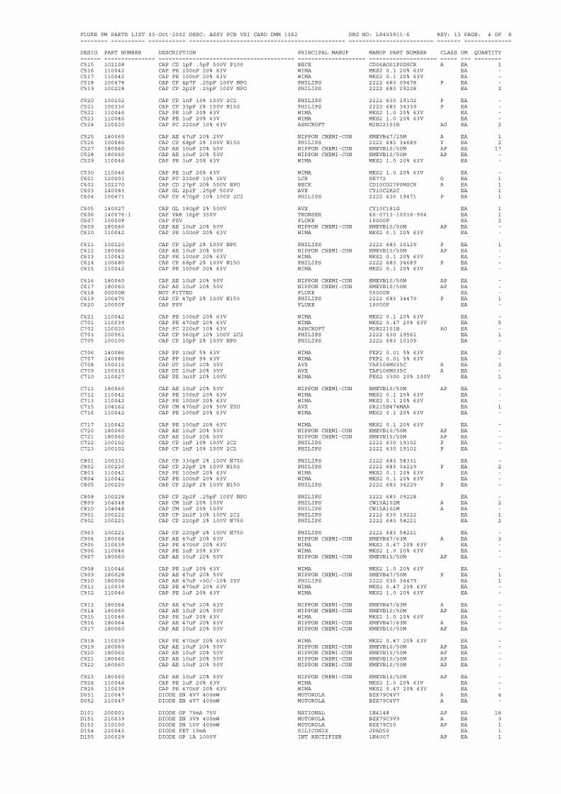
FLUKE PM PARTS LIST 03-Oct-2002 DESC: ASSY PCB VXI CARD DMM 1362 DRG NO: LP400911-6 REV: 13 PAGE: 4 OF 8======== ========== =========== ============================================== ========================= ======= ==============
DESIG PART NUMBER DESCRIPTION PRINCIPAL MANUF MANUF PART NUMBER CLASS UM QUANTITY====== =============== ======================================== ==================== ==================== ===== === ========C515 102108 CAP CD 1pF .5pF 500V P100 BECK CD06AG01P0DSCR A EA 1C516 110042 CAP PE 100nF 20% 63V WIMA MKS2 0.1 20% 63V EA -C517 110042 CAP PE 100nF 20% 63V WIMA MKS2 0.1 20% 63V EA -C518 100478 CAP CP 4p7F .25pF 100V NPO PHILIPS 2222 683 09478 P EA -C519 100228 CAP CP 2p2F .25pF 100V NPO PHILIPS 2222 683 09228 EA 2
C520 100102 CAP CP 1nF 10% 100V 2C2 PHILIPS 2222 630 19102 P EA -C521 100330 CAP CP 33pF 2% 100V N150 PHILIPS 2222 683 34339 P EA -C522 110046 CAP PE 1uF 20% 63V WIMA MKS2 1.0 20% 63V EA -C523 110046 CAP PE 1uF 20% 63V WIMA MKS2 1.0 20% 63V EA -C524 120020 CAP PC 220nF 10% 63V ASHCROFT M2B22101B AO EA 2
C525 180065 CAP AE 47uF 20% 25V NIPPON CHEMI-CON KMEVB47/25M A EA 1C526 100680 CAP CP 68pF 2% 100V N150 PHILIPS 2222 683 34689 P EA 2C527 180060 CAP AE 10uF 20% 50V NIPPON CHEMI-CON KMEVB10/50M AP EA 17C528 180060 CAP AE 10uF 20% 50V NIPPON CHEMI-CON KMEVB10/50M AP EA -C529 110046 CAP PE 1uF 20% 63V WIMA MKS2 1.0 20% 63V EA -
C530 110046 CAP PE 1uF 20% 63V WIMA MKS2 1.0 20% 63V EA -C601 120001 CAP PC 220nF 10% 1kV LCR SK772 O EA 1C602 102270 CAP CD 27pF 20% 500V NPO BECK CD10CG27P0MSCR A EA 1C603 140083 CAP GL 2p2F .25pF 500V AVX CY10C2R2C EA 1C604 100471 CAP CP 470pF 10% 100V 2C2 PHILIPS 2222 630 19471 P EA 1
C605 140027 CAP GL 180pF 2% 500V AVX CY10C181G EA 1C606 140076-1 CAP VAR 16pF 350V TRONSER 60-0713-10016-904 EA 1C607 10000F CAP FSV FLUKE 10000F EA 2C609 180060 CAP AE 10uF 20% 50V NIPPON CHEMI-CON KMEVB10/50M AP EA -C610 110042 CAP PE 100nF 20% 63V WIMA MKS2 0.1 20% 63V EA -
C611 100120 CAP CP 12pF 2% 100V NPO PHILIPS 2222 683 10129 P EA 1C612 180060 CAP AE 10uF 20% 50V NIPPON CHEMI-CON KMEVB10/50M AP EA -C613 110042 CAP PE 100nF 20% 63V WIMA MKS2 0.1 20% 63V EA -C614 100680 CAP CP 68pF 2% 100V N150 PHILIPS 2222 683 34689 P EA -C615 110042 CAP PE 100nF 20% 63V WIMA MKS2 0.1 20% 63V EA -
C616 180060 CAP AE 10uF 20% 50V NIPPON CHEMI-CON KMEVB10/50M AP EA -C617 180060 CAP AE 10uF 20% 50V NIPPON CHEMI-CON KMEVB10/50M AP EA -C618 00000N NOT FITTED FLUKE 00000N EA -C619 100470 CAP CP 47pF 2% 100V N150 PHILIPS 2222 683 34479 P EA 1C620 10000F CAP FSV FLUKE 10000F EA -
C621 110042 CAP PE 100nF 20% 63V WIMA MKS2 0.1 20% 63V EA -C701 110039 CAP PE 470nF 20% 63V WIMA MKS2 0.47 20% 63V EA 5C702 120020 CAP PC 220nF 10% 63V ASHCROFT M2B22101B AO EA -C703 100561 CAP CP 560pF 10% 100V 2C2 PHILIPS 2222 630 19561 EA 1C705 100100 CAP CP 10pF 2% 100V NPO PHILIPS 2222 683 10109 EA -
C706 140086 CAP PP 10nF 5% 63V WIMA FKP2 0.01 5% 63V EA 2C707 140086 CAP PP 10nF 5% 63V WIMA FKP2 0.01 5% 63V EA -C708 150015 CAP DT 10uF 20% 35V AVX TAP106M035C A EA 2C709 150015 CAP DT 10uF 20% 35V AVX TAP106M035C A EA -C710 110027 CAP PE 3n3F 20% 100V WIMA FKS2 3300 20% 100V EA 1
C711 180060 CAP AE 10uF 20% 50V NIPPON CHEMI-CON KMEVB10/50M AP EA -C712 110042 CAP PE 100nF 20% 63V WIMA MKS2 0.1 20% 63V EA -C713 110042 CAP PE 100nF 20% 63V WIMA MKS2 0.1 20% 63V EA -C715 104162 CAP CM 470nF 20% 50V Z5U AVX SR215E474MAA EA 1C716 110042 CAP PE 100nF 20% 63V WIMA MKS2 0.1 20% 63V EA -
C717 110042 CAP PE 100nF 20% 63V WIMA MKS2 0.1 20% 63V EA -C720 180060 CAP AE 10uF 20% 50V NIPPON CHEMI-CON KMEVB10/50M AP EA -C721 180060 CAP AE 10uF 20% 50V NIPPON CHEMI-CON KMEVB10/50M AP EA -C722 100102 CAP CP 1nF 10% 100V 2C2 PHILIPS 2222 630 19102 P EA -C723 100102 CAP CP 1nF 10% 100V 2C2 PHILIPS 2222 630 19102 P EA -
C801 100331 CAP CP 330pF 2% 100V N750 PHILIPS 2222 683 58331 EA -C802 100220 CAP CP 22pF 2% 100V N150 PHILIPS 2222 683 34229 P EA 2C803 110042 CAP PE 100nF 20% 63V WIMA MKS2 0.1 20% 63V EA -C804 110042 CAP PE 100nF 20% 63V WIMA MKS2 0.1 20% 63V EA -C805 100220 CAP CP 22pF 2% 100V N150 PHILIPS 2222 683 34229 P EA -
C808 100228 CAP CP 2p2F .25pF 100V NPO PHILIPS 2222 683 09228 EA -C809 104048 CAP CM 1nF 20% 100V PHILIPS CW15A102M A EA 2C810 104048 CAP CM 1nF 20% 100V PHILIPS CW15A102M A EA -C901 100222 CAP CP 2n2F 10% 100V 2C2 PHILIPS 2222 630 19222 EA 1C902 100221 CAP CP 220pF 2% 100V N750 PHILIPS 2222 683 58221 EA 2
C903 100221 CAP CP 220pF 2% 100V N750 PHILIPS 2222 683 58221 EA -C904 180064 CAP AE 47uF 20% 63V NIPPON CHEMI-CON KMEVB47/63M A EA 3C905 110039 CAP PE 470nF 20% 63V WIMA MKS2 0.47 20% 63V EA -C906 110046 CAP PE 1uF 20% 63V WIMA MKS2 1.0 20% 63V EA -C907 180060 CAP AE 10uF 20% 50V NIPPON CHEMI-CON KMEVB10/50M AP EA -
C908 110046 CAP PE 1uF 20% 63V WIMA MKS2 1.0 20% 63V EA -C909 180028 CAP AE 47uF 20% 50V NIPPON CHEMI-CON SMEVB47/50M P EA 1C910 180006 CAP AE 47uF +50/-10% 25V PHILIPS 2222 030 36479 EA 1C911 110039 CAP PE 470nF 20% 63V WIMA MKS2 0.47 20% 63V EA -C912 110046 CAP PE 1uF 20% 63V WIMA MKS2 1.0 20% 63V EA -
C913 180064 CAP AE 47uF 20% 63V NIPPON CHEMI-CON KMEVB47/63M A EA -C914 180060 CAP AE 10uF 20% 50V NIPPON CHEMI-CON KMEVB10/50M AP EA -C915 110046 CAP PE 1uF 20% 63V WIMA MKS2 1.0 20% 63V EA -C916 180064 CAP AE 47uF 20% 63V NIPPON CHEMI-CON KMEVB47/63M A EA -C917 180060 CAP AE 10uF 20% 50V NIPPON CHEMI-CON KMEVB10/50M AP EA -
C918 110039 CAP PE 470nF 20% 63V WIMA MKS2 0.47 20% 63V EA -C919 180060 CAP AE 10uF 20% 50V NIPPON CHEMI-CON KMEVB10/50M AP EA -C920 180060 CAP AE 10uF 20% 50V NIPPON CHEMI-CON KMEVB10/50M AP EA -C921 180060 CAP AE 10uF 20% 50V NIPPON CHEMI-CON KMEVB10/50M AP EA -C922 180060 CAP AE 10uF 20% 50V NIPPON CHEMI-CON KMEVB10/50M AP EA -
C923 180060 CAP AE 10uF 20% 50V NIPPON CHEMI-CON KMEVB10/50M AP EA -C924 110046 CAP PE 1uF 20% 63V WIMA MKS2 1.0 20% 63V EA -C925 110039 CAP PE 470nF 20% 63V WIMA MKS2 0.47 20% 63V EA -D051 210047 DIODE ZN 4V7 400mW MOTOROLA BZX79C4V7 A EA 4D052 210047 DIODE ZN 4V7 400mW MOTOROLA BZX79C4V7 A EA -
D101 200001 DIODE GP 75mA 75V NATIONAL 1N4148 AP EA 16D151 210039 DIODE ZN 3V9 400mW MOTOROLA BZX79C3V9 A EA 3D153 210100 DIODE ZN 10V 400mW MOTOROLA BZX79C10 AP EA 1D154 220043 DIODE FET 10mA SILICONIX JPAD50 EA 1D155 200029 DIODE GP 1A 1000V INT RECTIFIER 1N4007 AP EA 1

FLUKE PM PARTS LIST 03-Oct-2002 DESC: ASSY PCB VXI CARD DMM 1362 DRG NO: LP400911-6 REV: 13 PAGE: 5 OF 8======== ========== =========== ============================================== ========================= ======= ==============
DESIG PART NUMBER DESCRIPTION PRINCIPAL MANUF MANUF PART NUMBER CLASS UM QUANTITY====== =============== ======================================== ==================== ==================== ===== === ========D156 210051 DIODE ZN 5V1 400mW MOTOROLA BZX79C5V1 AP EA 4D157 200008 DIODE GP 200mA 125V NATIONAL 1N458A A EA 10D158 200008 DIODE GP 200mA 125V NATIONAL 1N458A A EA -D159 213033 DIODE ZN 6V8 2% 400mW PHILIPS BZX79B6V8 EA 3D201 400695-1 ASSY COM CATHODE DIODE FLUKE SEE DRG EA 1
D202 400696-1 ASSY COM ANODE DIODE FLUKE SEE DRG EA 1D203 220051 DIODE LE GRN 5V DIALIGHT 555-2303 EA 1D251 200001 DIODE GP 75mA 75V NATIONAL 1N4148 AP EA -D252 200001 DIODE GP 75mA 75V NATIONAL 1N4148 AP EA -D260 200001 DIODE GP 75mA 75V NATIONAL 1N4148 AP EA -
D302 210047 DIODE ZN 4V7 400mW MOTOROLA BZX79C4V7 A EA -D303 213006 DIODE TS 5V 5/500W UNITRODE TVS505 AP EA 1D401 220050 DIODE LE RED 5V DIALIGHT 555-2007 EA 1D402 220052 DIODE LE YLW 5V DIALIGHT 555-2403 EA 1D501 220010 DIODE SB AGILENT 1N6263 A EA 2
D502 220010 DIODE SB AGILENT 1N6263 A EA -D503 210056 DIODE ZN 5V6 400mW MOTOROLA BZX79C5V6 A EA 2D504 210056 DIODE ZN 5V6 400mW MOTOROLA BZX79C5V6 A EA -D505 200001 DIODE GP 75mA 75V NATIONAL 1N4148 AP EA -D508 200001 DIODE GP 75mA 75V NATIONAL 1N4148 AP EA -
D509 200008 DIODE GP 200mA 125V NATIONAL 1N458A A EA -D510 200008 DIODE GP 200mA 125V NATIONAL 1N458A A EA -D601 210068 DIODE ZN 6V8 400mW MOTOROLA BZX79C6V8 A EA 3D602 210068 DIODE ZN 6V8 400mW MOTOROLA BZX79C6V8 A EA -D603 210082 DIODE ZN 8V2 400mW MOTOROLA BZX79C8V2 AP EA 2
D604 210068 DIODE ZN 6V8 400mW MOTOROLA BZX79C6V8 A EA -D701 210051 DIODE ZN 5V1 400mW MOTOROLA BZX79C5V1 AP EA -D702 210051 DIODE ZN 5V1 400mW MOTOROLA BZX79C5V1 AP EA -D801 200008 DIODE GP 200mA 125V NATIONAL 1N458A A EA -D802 200008 DIODE GP 200mA 125V NATIONAL 1N458A A EA -
D803 200001 DIODE GP 75mA 75V NATIONAL 1N4148 AP EA -D804 200001 DIODE GP 75mA 75V NATIONAL 1N4148 AP EA -D805 200001 DIODE GP 75mA 75V NATIONAL 1N4148 AP EA -D806 200001 DIODE GP 75mA 75V NATIONAL 1N4148 AP EA -D807 210047 DIODE ZN 4V7 400mW MOTOROLA BZX79C4V7 A EA -
D808 210039 DIODE ZN 3V9 400mW MOTOROLA BZX79C3V9 A EA -D809 210039 DIODE ZN 3V9 400mW MOTOROLA BZX79C3V9 A EA -D810 213034 DIODE ZN 11V 2% 400mW PHILIPS BZX79B11 A EA 4D811 213034 DIODE ZN 11V 2% 400mW PHILIPS BZX79B11 A EA -D812 213033 DIODE ZN 6V8 2% 400mW PHILIPS BZX79B6V8 EA -
D813 213033 DIODE ZN 6V8 2% 400mW PHILIPS BZX79B6V8 EA -D816 200008 DIODE GP 200mA 125V NATIONAL 1N458A A EA -D817 200008 DIODE GP 200mA 125V NATIONAL 1N458A A EA -D820 200001 DIODE GP 75mA 75V NATIONAL 1N4148 AP EA -D821 200001 DIODE GP 75mA 75V NATIONAL 1N4148 AP EA -
D822 200008 DIODE GP 200mA 125V NATIONAL 1N458A A EA -D823 200008 DIODE GP 200mA 125V NATIONAL 1N458A A EA -D824 200001 DIODE GP 75mA 75V NATIONAL 1N4148 AP EA -D825 210091 DIODE ZN 9V1 400mW MOTOROLA BZX79C9V1 A EA 3D826 200001 DIODE GP 75mA 75V NATIONAL 1N4148 AP EA -
D827 213011 DIODE VR 1V4 250mW PHILIPS BZV86-1V4 EA 2D828 210082 DIODE ZN 8V2 400mW MOTOROLA BZX79C8V2 AP EA -D831 200001 DIODE GP 75mA 75V NATIONAL 1N4148 AP EA -D832 200001 DIODE GP 75mA 75V NATIONAL 1N4148 AP EA -D833 213034 DIODE ZN 11V 2% 400mW PHILIPS BZX79B11 A EA -
D834 210091 DIODE ZN 9V1 400mW MOTOROLA BZX79C9V1 A EA -D835 210091 DIODE ZN 9V1 400mW MOTOROLA BZX79C9V1 A EA -D836 213034 DIODE ZN 11V 2% 400mW PHILIPS BZX79B11 A EA -D901 210120 DIODE ZN 12V 400mW MOTOROLA BZX79C12 A EA 2D902 210120 DIODE ZN 12V 400mW MOTOROLA BZX79C12 A EA -
D903 200032 DIODE SB 1A 100V INT RECTIFIER 11DQ10 EA 9D904 213011 DIODE VR 1V4 250mW PHILIPS BZV86-1V4 EA -D905 200032 DIODE SB 1A 100V INT RECTIFIER 11DQ10 EA -D906 200032 DIODE SB 1A 100V INT RECTIFIER 11DQ10 EA -D907 200032 DIODE SB 1A 100V INT RECTIFIER 11DQ10 EA -
D908 200032 DIODE SB 1A 100V INT RECTIFIER 11DQ10 EA -D909 200032 DIODE SB 1A 100V INT RECTIFIER 11DQ10 EA -D910 200032 DIODE SB 1A 100V INT RECTIFIER 11DQ10 EA -D911 200032 DIODE SB 1A 100V INT RECTIFIER 11DQ10 EA -D912 210051 DIODE ZN 5V1 400mW MOTOROLA BZX79C5V1 AP EA -
D913 200032 DIODE SB 1A 100V INT RECTIFIER 11DQ10 EA -Q101 240001 TRAN NPN MOTOROLA BC184 A EA 5Q150 230019 TRAN MOSFET P-CHAN 40V TO72 VISHAY-SILICONIX 3N163 EA 2Q151 230019 TRAN MOSFET P-CHAN 40V TO72 VISHAY-SILICONIX 3N163 EA -Q152 230002 TRAN JFET N-CHAN VISHAY-SILICONIX J304 A EA 3
Q201 240001 TRAN NPN MOTOROLA BC184 A EA -Q202 240001 TRAN NPN MOTOROLA BC184 A EA -Q251 230086 TRAN MOSFET P-CHAN 60V ZETEX ZVP2106A EA 1Q252 00000N NOT FITTED FLUKE 00000N EA -Q253 00000N NOT FITTED FLUKE 00000N EA -
Q254 240029 TRAN NPN MOTOROLA BC546 AP EA 7Q255 250018 TRAN PNP MOTOROLA BC556 AP EA 5Q256 00000N NOT FITTED FLUKE 00000N EA -Q257 00000N NOT FITTED FLUKE 00000N EA -Q258 230082 TRAN MOSFET N-CHAN 60V VISHAY-SILICONIX VN10LM EA 2
Q259 230082 TRAN MOSFET N-CHAN 60V VISHAY-SILICONIX VN10LM EA -Q501 240001 TRAN NPN MOTOROLA BC184 A EA -Q502 250001 TRAN PNP MOTOROLA BC214 A EA 2Q503 250004 TRAN PNP TO92 MOTOROLA 2N3906 AP EA 4Q504 240006 TRAN NPN TO92 MOTOROLA 2N3904 AP EA 4
Q505 240001 TRAN NPN MOTOROLA BC184 A EA -Q506 250001 TRAN PNP MOTOROLA BC214 A EA -Q507 250004 TRAN PNP TO92 MOTOROLA 2N3906 AP EA -Q508 240006 TRAN NPN TO92 MOTOROLA 2N3904 AP EA -Q601 230101 TRAN MOSFET N-CHAN INFINEON BSS229 EA 4
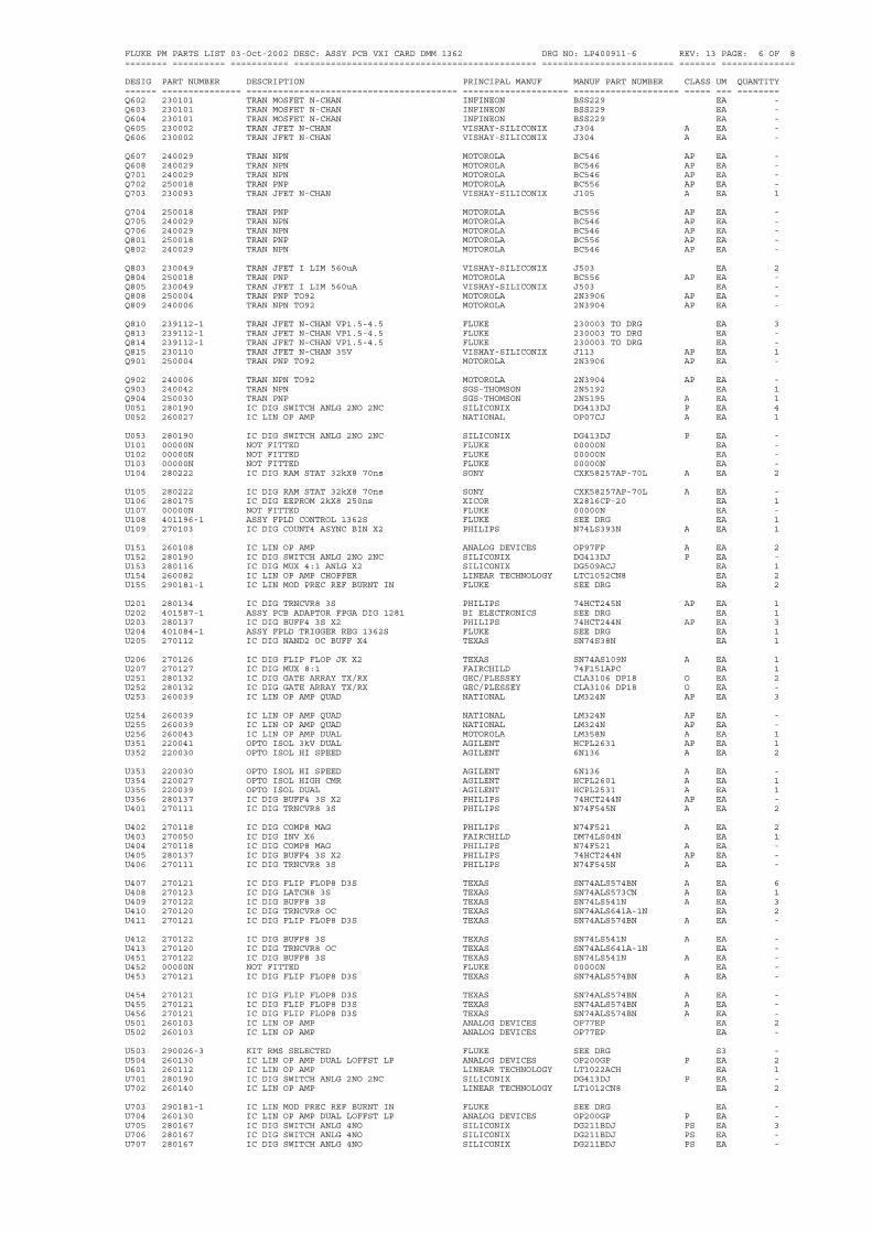
FLUKE PM PARTS LIST 03-Oct-2002 DESC: ASSY PCB VXI CARD DMM 1362 DRG NO: LP400911-6 REV: 13 PAGE: 6 OF 8======== ========== =========== ============================================== ========================= ======= ==============
DESIG PART NUMBER DESCRIPTION PRINCIPAL MANUF MANUF PART NUMBER CLASS UM QUANTITY====== =============== ======================================== ==================== ==================== ===== === ========Q602 230101 TRAN MOSFET N-CHAN INFINEON BSS229 EA -Q603 230101 TRAN MOSFET N-CHAN INFINEON BSS229 EA -Q604 230101 TRAN MOSFET N-CHAN INFINEON BSS229 EA -Q605 230002 TRAN JFET N-CHAN VISHAY-SILICONIX J304 A EA -Q606 230002 TRAN JFET N-CHAN VISHAY-SILICONIX J304 A EA -
Q607 240029 TRAN NPN MOTOROLA BC546 AP EA -Q608 240029 TRAN NPN MOTOROLA BC546 AP EA -Q701 240029 TRAN NPN MOTOROLA BC546 AP EA -Q702 250018 TRAN PNP MOTOROLA BC556 AP EA -Q703 230093 TRAN JFET N-CHAN VISHAY-SILICONIX J105 A EA 1
Q704 250018 TRAN PNP MOTOROLA BC556 AP EA -Q705 240029 TRAN NPN MOTOROLA BC546 AP EA -Q706 240029 TRAN NPN MOTOROLA BC546 AP EA -Q801 250018 TRAN PNP MOTOROLA BC556 AP EA -Q802 240029 TRAN NPN MOTOROLA BC546 AP EA -
Q803 230049 TRAN JFET I LIM 560uA VISHAY-SILICONIX J503 EA 2Q804 250018 TRAN PNP MOTOROLA BC556 AP EA -Q805 230049 TRAN JFET I LIM 560uA VISHAY-SILICONIX J503 EA -Q808 250004 TRAN PNP TO92 MOTOROLA 2N3906 AP EA -Q809 240006 TRAN NPN TO92 MOTOROLA 2N3904 AP EA -
Q810 239112-1 TRAN JFET N-CHAN VP1.5-4.5 FLUKE 230003 TO DRG EA 3Q813 239112-1 TRAN JFET N-CHAN VP1.5-4.5 FLUKE 230003 TO DRG EA -Q814 239112-1 TRAN JFET N-CHAN VP1.5-4.5 FLUKE 230003 TO DRG EA -Q815 230110 TRAN JFET N-CHAN 35V VISHAY-SILICONIX J113 AP EA 1Q901 250004 TRAN PNP TO92 MOTOROLA 2N3906 AP EA -
Q902 240006 TRAN NPN TO92 MOTOROLA 2N3904 AP EA -Q903 240042 TRAN NPN SGS-THOMSON 2N5192 EA 1Q904 250030 TRAN PNP SGS-THOMSON 2N5195 A EA 1U051 280190 IC DIG SWITCH ANLG 2NO 2NC SILICONIX DG413DJ P EA 4U052 260027 IC LIN OP AMP NATIONAL OP07CJ A EA 1
U053 280190 IC DIG SWITCH ANLG 2NO 2NC SILICONIX DG413DJ P EA -U101 00000N NOT FITTED FLUKE 00000N EA -U102 00000N NOT FITTED FLUKE 00000N EA -U103 00000N NOT FITTED FLUKE 00000N EA -U104 280222 IC DIG RAM STAT 32kX8 70ns SONY CXK58257AP-70L A EA 2
U105 280222 IC DIG RAM STAT 32kX8 70ns SONY CXK58257AP-70L A EA -U106 280175 IC DIG EEPROM 2kX8 250ns XICOR X2816CP-20 EA 1U107 00000N NOT FITTED FLUKE 00000N EA -U108 401196-1 ASSY FPLD CONTROL 1362S FLUKE SEE DRG EA 1U109 270103 IC DIG COUNT4 ASYNC BIN X2 PHILIPS N74LS393N A EA 1
U151 260108 IC LIN OP AMP ANALOG DEVICES OP97FP A EA 2U152 280190 IC DIG SWITCH ANLG 2NO 2NC SILICONIX DG413DJ P EA -U153 280116 IC DIG MUX 4:1 ANLG X2 SILICONIX DG509ACJ EA 1U154 260082 IC LIN OP AMP CHOPPER LINEAR TECHNOLOGY LTC1052CN8 EA 2U155 290181-1 IC LIN MOD PREC REF BURNT IN FLUKE SEE DRG EA 2
U201 280134 IC DIG TRNCVR8 3S PHILIPS 74HCT245N AP EA 1U202 401587-1 ASSY PCB ADAPTOR FPGA DIG 1281 BI ELECTRONICS SEE DRG EA 1U203 280137 IC DIG BUFF4 3S X2 PHILIPS 74HCT244N AP EA 3U204 401084-1 ASSY FPLD TRIGGER REG 1362S FLUKE SEE DRG EA 1U205 270112 IC DIG NAND2 OC BUFF X4 TEXAS SN74S38N EA 1
U206 270126 IC DIG FLIP FLOP JK X2 TEXAS SN74AS109N A EA 1U207 270127 IC DIG MUX 8:1 FAIRCHILD 74F151APC EA 1U251 280132 IC DIG GATE ARRAY TX/RX GEC/PLESSEY CLA3106 DP18 O EA 2U252 280132 IC DIG GATE ARRAY TX/RX GEC/PLESSEY CLA3106 DP18 O EA -U253 260039 IC LIN OP AMP QUAD NATIONAL LM324N AP EA 3
U254 260039 IC LIN OP AMP QUAD NATIONAL LM324N AP EA -U255 260039 IC LIN OP AMP QUAD NATIONAL LM324N AP EA -U256 260043 IC LIN OP AMP DUAL MOTOROLA LM358N A EA 1U351 220041 OPTO ISOL 3kV DUAL AGILENT HCPL2631 AP EA 1U352 220030 OPTO ISOL HI SPEED AGILENT 6N136 A EA 2
U353 220030 OPTO ISOL HI SPEED AGILENT 6N136 A EA -U354 220027 OPTO ISOL HIGH CMR AGILENT HCPL2601 A EA 1U355 220039 OPTO ISOL DUAL AGILENT HCPL2531 A EA 1U356 280137 IC DIG BUFF4 3S X2 PHILIPS 74HCT244N AP EA -U401 270111 IC DIG TRNCVR8 3S PHILIPS N74F545N A EA 2
U402 270118 IC DIG COMP8 MAG PHILIPS N74F521 A EA 2U403 270050 IC DIG INV X6 FAIRCHILD DM74LS04N EA 1U404 270118 IC DIG COMP8 MAG PHILIPS N74F521 A EA -U405 280137 IC DIG BUFF4 3S X2 PHILIPS 74HCT244N AP EA -U406 270111 IC DIG TRNCVR8 3S PHILIPS N74F545N A EA -
U407 270121 IC DIG FLIP FLOP8 D3S TEXAS SN74ALS574BN A EA 6U408 270123 IC DIG LATCH8 3S TEXAS SN74ALS573CN A EA 1U409 270122 IC DIG BUFF8 3S TEXAS SN74LS541N A EA 3U410 270120 IC DIG TRNCVR8 OC TEXAS SN74ALS641A-1N EA 2U411 270121 IC DIG FLIP FLOP8 D3S TEXAS SN74ALS574BN A EA -
U412 270122 IC DIG BUFF8 3S TEXAS SN74LS541N A EA -U413 270120 IC DIG TRNCVR8 OC TEXAS SN74ALS641A-1N EA -U451 270122 IC DIG BUFF8 3S TEXAS SN74LS541N A EA -U452 00000N NOT FITTED FLUKE 00000N EA -U453 270121 IC DIG FLIP FLOP8 D3S TEXAS SN74ALS574BN A EA -
U454 270121 IC DIG FLIP FLOP8 D3S TEXAS SN74ALS574BN A EA -U455 270121 IC DIG FLIP FLOP8 D3S TEXAS SN74ALS574BN A EA -U456 270121 IC DIG FLIP FLOP8 D3S TEXAS SN74ALS574BN A EA -U501 260103 IC LIN OP AMP ANALOG DEVICES OP77EP EA 2U502 260103 IC LIN OP AMP ANALOG DEVICES OP77EP EA -
U503 290026-3 KIT RMS SELECTED FLUKE SEE DRG S3 -U504 260130 IC LIN OP AMP DUAL LOFFST LP ANALOG DEVICES OP200GP P EA 2U601 260112 IC LIN OP AMP LINEAR TECHNOLOGY LT1022ACH EA 1U701 280190 IC DIG SWITCH ANLG 2NO 2NC SILICONIX DG413DJ P EA -U702 260140 IC LIN OP AMP LINEAR TECHNOLOGY LT1012CN8 EA 2
U703 290181-1 IC LIN MOD PREC REF BURNT IN FLUKE SEE DRG EA -U704 260130 IC LIN OP AMP DUAL LOFFST LP ANALOG DEVICES OP200GP P EA -U705 280167 IC DIG SWITCH ANLG 4NO SILICONIX DG211BDJ PS EA 3U706 280167 IC DIG SWITCH ANLG 4NO SILICONIX DG211BDJ PS EA -U707 280167 IC DIG SWITCH ANLG 4NO SILICONIX DG211BDJ PS EA -
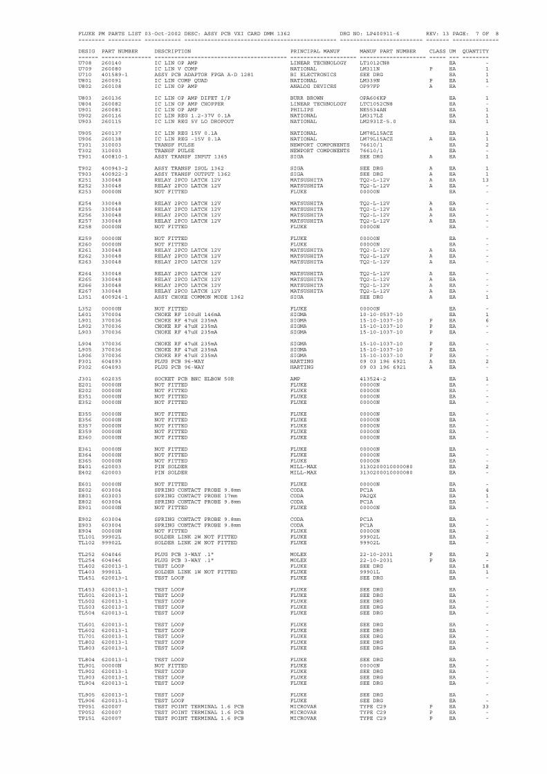
FLUKE PM PARTS LIST 03-Oct-2002 DESC: ASSY PCB VXI CARD DMM 1362 DRG NO: LP400911-6 REV: 13 PAGE: 7 OF 8======== ========== =========== ============================================== ========================= ======= ==============
DESIG PART NUMBER DESCRIPTION PRINCIPAL MANUF MANUF PART NUMBER CLASS UM QUANTITY====== =============== ======================================== ==================== ==================== ===== === ========U708 260140 IC LIN OP AMP LINEAR TECHNOLOGY LT1012CN8 EA -U709 260080 IC LIN V COMP NATIONAL LM311N P EA 1U710 401589-1 ASSY PCB ADAPTOR FPGA A-D 1281 BI ELECTRONICS SEE DRG EA 1U801 260091 IC LIN COMP QUAD NATIONAL LM339N P EA 1U802 260108 IC LIN OP AMP ANALOG DEVICES OP97FP A EA -
U803 260136 IC LIN OP AMP DIFET I/P BURR BROWN OPA606KP EA 1U804 260082 IC LIN OP AMP CHOPPER LINEAR TECHNOLOGY LTC1052CN8 EA -U901 260081 IC LIN OP AMP PHILIPS NE5534AN EA 1U902 260116 IC LIN REG 1.2-37V 0.1A NATIONAL LM317LZ EA 1U903 260115 IC LIN REG 5V LO DROPOUT NATIONAL LM2931Z-5.0 EA 1
U905 260137 IC LIN REG 15V 0.1A NATIONAL LM78L15ACZ EA 1U906 260138 IC LIN REG -15V 0.1A NATIONAL LM79L15ACZ A EA 1T301 310003 TRANSF PULSE NEWPORT COMPONENTS 76610/1 EA 2T302 310003 TRANSF PULSE NEWPORT COMPONENTS 76610/1 EA -T901 400810-1 ASSY TRANSF INPUT 1365 SIGA SEE DRG A EA 1
T902 400943-2 ASSY TRANSF ISOL 1362 SIGA SEE DRG A EA 1T903 400922-3 ASSY TRANSF OUTPUT 1362 SIGA SEE DRG A EA 1K251 330048 RELAY 2PCO LATCH 12V MATSUSHITA TQ2-L-12V A EA 13K252 330048 RELAY 2PCO LATCH 12V MATSUSHITA TQ2-L-12V A EA -K253 00000N NOT FITTED FLUKE 00000N EA -
K254 330048 RELAY 2PCO LATCH 12V MATSUSHITA TQ2-L-12V A EA -K255 330048 RELAY 2PCO LATCH 12V MATSUSHITA TQ2-L-12V A EA -K256 330048 RELAY 2PCO LATCH 12V MATSUSHITA TQ2-L-12V A EA -K257 330048 RELAY 2PCO LATCH 12V MATSUSHITA TQ2-L-12V A EA -K258 00000N NOT FITTED FLUKE 00000N EA -
K259 00000N NOT FITTED FLUKE 00000N EA -K260 00000N NOT FITTED FLUKE 00000N EA -K261 330048 RELAY 2PCO LATCH 12V MATSUSHITA TQ2-L-12V A EA -K262 330048 RELAY 2PCO LATCH 12V MATSUSHITA TQ2-L-12V A EA -K263 330048 RELAY 2PCO LATCH 12V MATSUSHITA TQ2-L-12V A EA -
K264 330048 RELAY 2PCO LATCH 12V MATSUSHITA TQ2-L-12V A EA -K265 330048 RELAY 2PCO LATCH 12V MATSUSHITA TQ2-L-12V A EA -K266 330048 RELAY 2PCO LATCH 12V MATSUSHITA TQ2-L-12V A EA -K267 330048 RELAY 2PCO LATCH 12V MATSUSHITA TQ2-L-12V A EA -L351 400924-1 ASSY CHOKE COMMON MODE 1362 SIGA SEE DRG A EA 1
L352 00000N NOT FITTED FLUKE 00000N EA -L601 370004 CHOKE RF 100uH 146mA SIGMA 10-10-0537-10 EA 1L901 370036 CHOKE RF 47uH 235mA SIGMA 15-10-1037-10 P EA 6L902 370036 CHOKE RF 47uH 235mA SIGMA 15-10-1037-10 P EA -L903 370036 CHOKE RF 47uH 235mA SIGMA 15-10-1037-10 P EA -
L904 370036 CHOKE RF 47uH 235mA SIGMA 15-10-1037-10 P EA -L905 370036 CHOKE RF 47uH 235mA SIGMA 15-10-1037-10 P EA -L906 370036 CHOKE RF 47uH 235mA SIGMA 15-10-1037-10 P EA -P301 604093 PLUG PCB 96-WAY HARTING 09 03 196 6921 A EA 2P302 604093 PLUG PCB 96-WAY HARTING 09 03 196 6921 A EA -
J301 602035 SOCKET PCB BNC ELBOW 50R AMP 413524-2 EA 1E201 00000N NOT FITTED FLUKE 00000N EA -E202 00000N NOT FITTED FLUKE 00000N EA -E351 00000N NOT FITTED FLUKE 00000N EA -E352 00000N NOT FITTED FLUKE 00000N EA -
E355 00000N NOT FITTED FLUKE 00000N EA -E356 00000N NOT FITTED FLUKE 00000N EA -E357 00000N NOT FITTED FLUKE 00000N EA -E359 00000N NOT FITTED FLUKE 00000N EA -E360 00000N NOT FITTED FLUKE 00000N EA -
E361 00000N NOT FITTED FLUKE 00000N EA -E364 00000N NOT FITTED FLUKE 00000N EA -E365 00000N NOT FITTED FLUKE 00000N EA -E401 620003 PIN SOLDER MILL-MAX 3130200010000080 EA 2E402 620003 PIN SOLDER MILL-MAX 3130200010000080 EA -
E601 00000N NOT FITTED FLUKE 00000N EA -E602 603004 SPRING CONTACT PROBE 9.8mm CODA PC1A EA 4E801 603003 SPRING CONTACT PROBE 17mm CODA PA2QX EA 1E802 603004 SPRING CONTACT PROBE 9.8mm CODA PC1A EA -E901 00000N NOT FITTED FLUKE 00000N EA -
E902 603004 SPRING CONTACT PROBE 9.8mm CODA PC1A EA -E903 603004 SPRING CONTACT PROBE 9.8mm CODA PC1A EA -E904 00000N NOT FITTED FLUKE 00000N EA -TL101 99902L SOLDER LINK 2W NOT FITTED FLUKE 99902L EA 2TL102 99902L SOLDER LINK 2W NOT FITTED FLUKE 99902L EA -
TL252 604046 PLUG PCB 3-WAY .1" MOLEX 22-10-2031 P EA 2TL254 604046 PLUG PCB 3-WAY .1" MOLEX 22-10-2031 P EA -TL402 620013-1 TEST LOOP FLUKE SEE DRG EA 18TL403 99901L SOLDER LINK 1W NOT FITTED FLUKE 99901L EA 1TL451 620013-1 TEST LOOP FLUKE SEE DRG EA -
TL453 620013-1 TEST LOOP FLUKE SEE DRG EA -TL501 620013-1 TEST LOOP FLUKE SEE DRG EA -TL502 620013-1 TEST LOOP FLUKE SEE DRG EA -TL503 620013-1 TEST LOOP FLUKE SEE DRG EA -TL504 620013-1 TEST LOOP FLUKE SEE DRG EA -
TL601 620013-1 TEST LOOP FLUKE SEE DRG EA -TL602 620013-1 TEST LOOP FLUKE SEE DRG EA -TL701 620013-1 TEST LOOP FLUKE SEE DRG EA -TL802 620013-1 TEST LOOP FLUKE SEE DRG EA -TL803 620013-1 TEST LOOP FLUKE SEE DRG EA -
TL804 620013-1 TEST LOOP FLUKE SEE DRG EA -TL901 00000N NOT FITTED FLUKE 00000N EA -TL902 620013-1 TEST LOOP FLUKE SEE DRG EA -TL903 620013-1 TEST LOOP FLUKE SEE DRG EA -TL904 620013-1 TEST LOOP FLUKE SEE DRG EA -
TL905 620013-1 TEST LOOP FLUKE SEE DRG EA -TL906 620013-1 TEST LOOP FLUKE SEE DRG EA -TP051 620007 TEST POINT TERMINAL 1.6 PCB MICROVAR TYPE C29 P EA 33TP052 620007 TEST POINT TERMINAL 1.6 PCB MICROVAR TYPE C29 P EA -TP151 620007 TEST POINT TERMINAL 1.6 PCB MICROVAR TYPE C29 P EA -

FLUKE PM PARTS LIST 03-Oct-2002 DESC: ASSY PCB VXI CARD DMM 1362 DRG NO: LP400911-6 REV: 13 PAGE: 8 OF 8======== ========== =========== ============================================== ========================= ======= ==============
DESIG PART NUMBER DESCRIPTION PRINCIPAL MANUF MANUF PART NUMBER CLASS UM QUANTITY====== =============== ======================================== ==================== ==================== ===== === ========TP153 620007 TEST POINT TERMINAL 1.6 PCB MICROVAR TYPE C29 P EA -TP154 620007 TEST POINT TERMINAL 1.6 PCB MICROVAR TYPE C29 P EA -TP155 620007 TEST POINT TERMINAL 1.6 PCB MICROVAR TYPE C29 P EA -TP351 620007 TEST POINT TERMINAL 1.6 PCB MICROVAR TYPE C29 P EA -TP352 620007 TEST POINT TERMINAL 1.6 PCB MICROVAR TYPE C29 P EA -
TP353 620007 TEST POINT TERMINAL 1.6 PCB MICROVAR TYPE C29 P EA -TP354 620007 TEST POINT TERMINAL 1.6 PCB MICROVAR TYPE C29 P EA -TP501 620007 TEST POINT TERMINAL 1.6 PCB MICROVAR TYPE C29 P EA -TP502 620007 TEST POINT TERMINAL 1.6 PCB MICROVAR TYPE C29 P EA -TP503 620007 TEST POINT TERMINAL 1.6 PCB MICROVAR TYPE C29 P EA -
TP504 620007 TEST POINT TERMINAL 1.6 PCB MICROVAR TYPE C29 P EA -TP505 620007 TEST POINT TERMINAL 1.6 PCB MICROVAR TYPE C29 P EA -TP506 620007 TEST POINT TERMINAL 1.6 PCB MICROVAR TYPE C29 P EA -TP601 620007 TEST POINT TERMINAL 1.6 PCB MICROVAR TYPE C29 P EA -TP602 620007 TEST POINT TERMINAL 1.6 PCB MICROVAR TYPE C29 P EA -
TP603 620007 TEST POINT TERMINAL 1.6 PCB MICROVAR TYPE C29 P EA -TP604 620007 TEST POINT TERMINAL 1.6 PCB MICROVAR TYPE C29 P EA -TP701 620007 TEST POINT TERMINAL 1.6 PCB MICROVAR TYPE C29 P EA -TP702 620007 TEST POINT TERMINAL 1.6 PCB MICROVAR TYPE C29 P EA -TP703 620007 TEST POINT TERMINAL 1.6 PCB MICROVAR TYPE C29 P EA -
TP704 620007 TEST POINT TERMINAL 1.6 PCB MICROVAR TYPE C29 P EA -TP705 620007 TEST POINT TERMINAL 1.6 PCB MICROVAR TYPE C29 P EA -TP706 620007 TEST POINT TERMINAL 1.6 PCB MICROVAR TYPE C29 P EA -TP801 620007 TEST POINT TERMINAL 1.6 PCB MICROVAR TYPE C29 P EA -TP804 620007 TEST POINT TERMINAL 1.6 PCB MICROVAR TYPE C29 P EA -
TP901 620007 TEST POINT TERMINAL 1.6 PCB MICROVAR TYPE C29 P EA -TP902 620007 TEST POINT TERMINAL 1.6 PCB MICROVAR TYPE C29 P EA -TP903 620007 TEST POINT TERMINAL 1.6 PCB MICROVAR TYPE C29 P EA -TP906 620007 TEST POINT TERMINAL 1.6 PCB MICROVAR TYPE C29 P EA -TP909 620007 TEST POINT TERMINAL 1.6 PCB MICROVAR TYPE C29 P EA -
S402 700128 SWITCH 1PCO SLIDE MORS 25336N A EA 1S403 700127 SWITCH 1PST X 8 DIL HIGHLAND 76SB08 A EA 1Y101 800035 CRYSTAL OSC 16MHz IQD 16MHz IQXO-100 EA 1Y701 800032 CRYSTAL OSC 4.91520MHz EUROQUARTZ EQX0-1100HC-4.9152MH EA 1F351 00000N NOT FITTED FLUKE 00000N EA -
#1 104056 CAP CI 20nF 50V DIL14 ROGERS CORP 203A14 EA 1#1 414009-2 PCB VXI DMM 1362S INVOTEC SEE DRG EA 1#1 420098 LABEL SER/ASSY No 19x6 TH WHT BRADY THT-1-497-10 P EA 1#1 420112-1 LABEL SSD WARNING 12 X 12mm BRADY SSW8D AP EA 1#1 540002 WIRE 1/.7 TINNED COPPER 22SWG BICC BS4109 A AR 1
#1 602001 TERMINAL FSV MILL-MAX 1065015013002102 A EA 4#1 602025 SOCKET PCB 1.0mm DIA HARWIN H3163-01 EA 1#1 604171 PLUG ADAPTOR 40-WAY DIL SAMTEC APA-640-G-A1 EA 1#1 605061 SOCKET PCB 16-WAY DIL JERMYN J23-18016 A EA 1#1 605062 SOCKET PCB 18-WAY DIL JERMYN J23-18018 A EA 2
#1 605064 SOCKET PCB 24-WAY DIL JERMYN J23-18024 A EA 1#1 605065 SOCKET PCB 28-WAY DIL JERMYN J23-18028 A EA 4#1 605070 SOCKET PCB 20-WAY DIL JERMYN J23-18020 A EA 2#1 605127 SOCKET LINK 2-WAY .1" BLK ASSMANN AKSPL-G EA 2#1 605175 SOCKET PCB 24-WAY DIL 0.3P HARWIN D2924 A EA 3
#1 605204 SOCKET PCB 68-WAY JLCC BURNDY QILE68P-41OT EA 2#1 605205 SOCKET PCB 84-WAY JLCC BURNDY QILE84P-410T AP EA 1#1 611023 SCREW M2.5 X 10 POZIPAN SZP GKN SEE DRG DP611000 EA 4#1 612004-1 STANDOFF M3 X 4 SWIFT ENGINEERING SEE DRG EA 2#1 612055-1 STANDOFF M3 X 19.0 SWIFT ENGINEERING SEE DRG EA 2
#1 615006 NUT FULL M2.5 SZP GKN SEE DRG DP611000 EA 4#1 618018 PAD MTG TO18 X 5.5mm JERMYN TO18-006 A EA 2#1 630024 BEAD CERAMIC 16 SWG PARK ROYAL PORCELAIN No2/D0006 EA 8#1 630044 GROMMET STRIP SIZE 3 CRITCHLEY 0495 AR 1#1 630243 BEAD GLASS 2.4 X 0.81 X 1.8 MANSOL PREFORMS LT M5363B/3 EA 6
#1 920145 FERRITE 3 OD 0.7 ID 4 LG PHILIPS FX4026 A EA 2
Wavetek's Regional Sales and Service Offices
Sales & Service
CHINA
Wavetek Corporation
Room 2701, Citic Building,No. 19 Jianguomenwai Dajie,Beijing 100004,PRC
Tel: 86 10 6592 8044 Fax: 86 10 6500 8199
GERMANY
Wavetek GmbH
Gutenbergstrasse 2-4,85737 IsmaningGermany
Tel: 49 89 996 41 0Fax: 49 89 996 41 160
www.wavetek.com
UNITED KINGDOM
Wavetek Test & Measurement Division
52 Hurricane Way,Norwich Airport,Norwich NR6 6JB,England
Tel: 44 1603 256 600 Fax: 44 1603 483 670
UNITED STATES of AMERICA
Wavetek Corporation Sales & Service
9045 Balboa Avenue,San Diego,CA 92123 USA
Tel: 619 279 2200 Fax: 619 450 0325
WT1

Related Documents