January 2019 UM2523 Rev 1 1/231 1 UM2523 User manual ST Teseo III ROM binary image - User manual Introduction ST Teseo III ROM binary image is the official binary software used on several ST Teseo III ROM systems. This document is relevant for the following Baseband Processors and related GNSS software products. Any other specific constraints related to version of products and software are specified inside the document. Table 1. ST GNSS Teseo III ROM supported devices Device type Teseo-LIV3R STA8090WGR STA8089GR www.st.com

Welcome message from author
This document is posted to help you gain knowledge. Please leave a comment to let me know what you think about it! Share it to your friends and learn new things together.
Transcript

January 2019 UM2523 Rev 1 1/231
1
UM2523User manual
ST Teseo III ROM binary image - User manual
Introduction
ST Teseo III ROM binary image is the official binary software used on several ST Teseo III ROM systems.
This document is relevant for the following Baseband Processors and related GNSS software products. Any other specific constraints related to version of products and software are specified inside the document.
Table 1. ST GNSS Teseo III ROM supported devices
Device type
Teseo-LIV3R
STA8090WGR
STA8089GR
www.st.com
Contents UM2523
2/231 UM2523 Rev 1
Contents
1 GNSS ROM Binary introduction . . . . . . . . . . . . . . . . . . . . . . . . . . . . . . . 17
1.1 GNSS ROM binary components description . . . . . . . . . . . . . . . . . . . . . . 17
2 GNSS binary configuration . . . . . . . . . . . . . . . . . . . . . . . . . . . . . . . . . . 19
2.1 Binary configuration . . . . . . . . . . . . . . . . . . . . . . . . . . . . . . . . . . . . . . . . . 19
2.1.1 Configuration concept . . . . . . . . . . . . . . . . . . . . . . . . . . . . . . . . . . . . . . 19
2.2 Binary version . . . . . . . . . . . . . . . . . . . . . . . . . . . . . . . . . . . . . . . . . . . . . . 20
3 Assisted GNSS . . . . . . . . . . . . . . . . . . . . . . . . . . . . . . . . . . . . . . . . . . . . 22
3.1 RealTime AGNSS . . . . . . . . . . . . . . . . . . . . . . . . . . . . . . . . . . . . . . . . . . 22
3.1.1 Password generation . . . . . . . . . . . . . . . . . . . . . . . . . . . . . . . . . . . . . . . 23
4 Geofencing . . . . . . . . . . . . . . . . . . . . . . . . . . . . . . . . . . . . . . . . . . . . . . . . 24
5 Odometer . . . . . . . . . . . . . . . . . . . . . . . . . . . . . . . . . . . . . . . . . . . . . . . . . 26
6 Communication interface . . . . . . . . . . . . . . . . . . . . . . . . . . . . . . . . . . . . 28
6.1 Commands . . . . . . . . . . . . . . . . . . . . . . . . . . . . . . . . . . . . . . . . . . . . . . . . 28
6.2 Messages . . . . . . . . . . . . . . . . . . . . . . . . . . . . . . . . . . . . . . . . . . . . . . . . . 28
6.2.1 Standard NMEA messages . . . . . . . . . . . . . . . . . . . . . . . . . . . . . . . . . . 29
6.2.2 Proprietary messages . . . . . . . . . . . . . . . . . . . . . . . . . . . . . . . . . . . . . . 29
7 Low power modes . . . . . . . . . . . . . . . . . . . . . . . . . . . . . . . . . . . . . . . . . . 30
7.1 Mode maturity . . . . . . . . . . . . . . . . . . . . . . . . . . . . . . . . . . . . . . . . . . . . . . 30
7.2 Periodic mode . . . . . . . . . . . . . . . . . . . . . . . . . . . . . . . . . . . . . . . . . . . . . 31
7.2.1 State machine . . . . . . . . . . . . . . . . . . . . . . . . . . . . . . . . . . . . . . . . . . . . 31
7.2.2 Good GNSS coverage sequences . . . . . . . . . . . . . . . . . . . . . . . . . . . . . 33
7.2.3 Poor GNSS coverage sequences . . . . . . . . . . . . . . . . . . . . . . . . . . . . . 34
7.3 Shutdown . . . . . . . . . . . . . . . . . . . . . . . . . . . . . . . . . . . . . . . . . . . . . . . . . 34
8 Antenna detection . . . . . . . . . . . . . . . . . . . . . . . . . . . . . . . . . . . . . . . . . . 36
8.1 Antenna detection algorithm . . . . . . . . . . . . . . . . . . . . . . . . . . . . . . . . . . . 36
8.1.1 Antenna detection algorithm: ADC implementation . . . . . . . . . . . . . . . . 37
8.1.2 Antenna detection algorithm: GPIO implementation . . . . . . . . . . . . . . . 38

UM2523 Rev 1 3/231
UM2523 Contents
11
8.2 ADC channels reading . . . . . . . . . . . . . . . . . . . . . . . . . . . . . . . . . . . . . . . 40
9 Commands . . . . . . . . . . . . . . . . . . . . . . . . . . . . . . . . . . . . . . . . . . . . . . . . 41
9.1 Software command list . . . . . . . . . . . . . . . . . . . . . . . . . . . . . . . . . . . . . . . 41
9.2 ST NMEA command specification . . . . . . . . . . . . . . . . . . . . . . . . . . . . . . 43
9.2.1 $PSTMINITGPS . . . . . . . . . . . . . . . . . . . . . . . . . . . . . . . . . . . . . . . . . . 43
9.2.2 $PSTMINITTIME . . . . . . . . . . . . . . . . . . . . . . . . . . . . . . . . . . . . . . . . . . 44
9.2.3 $PSTMINITFRQ . . . . . . . . . . . . . . . . . . . . . . . . . . . . . . . . . . . . . . . . . . 45
9.2.4 $PSTMSETRANGE . . . . . . . . . . . . . . . . . . . . . . . . . . . . . . . . . . . . . . . . 45
9.2.5 $PSTMCLREPHS . . . . . . . . . . . . . . . . . . . . . . . . . . . . . . . . . . . . . . . . . 46
9.2.6 $PSTMDUMPEPHEMS . . . . . . . . . . . . . . . . . . . . . . . . . . . . . . . . . . . . . 46
9.2.7 $PSTMEPHEM . . . . . . . . . . . . . . . . . . . . . . . . . . . . . . . . . . . . . . . . . . . 46
9.2.8 $PSTMCLRALMS . . . . . . . . . . . . . . . . . . . . . . . . . . . . . . . . . . . . . . . . . 51
9.2.9 $PSTMDUMPALMANAC . . . . . . . . . . . . . . . . . . . . . . . . . . . . . . . . . . . . 51
9.2.10 $PSTMALMANAC . . . . . . . . . . . . . . . . . . . . . . . . . . . . . . . . . . . . . . . . . 52
9.2.11 $PSTMCOLD . . . . . . . . . . . . . . . . . . . . . . . . . . . . . . . . . . . . . . . . . . . . . 54
9.2.12 $PSTMWARM . . . . . . . . . . . . . . . . . . . . . . . . . . . . . . . . . . . . . . . . . . . . 54
9.2.13 $PSTMHOT . . . . . . . . . . . . . . . . . . . . . . . . . . . . . . . . . . . . . . . . . . . . . . 54
9.2.14 $PSTMNMEAONOFF . . . . . . . . . . . . . . . . . . . . . . . . . . . . . . . . . . . . . . 55
9.2.15 $PSTMSRR . . . . . . . . . . . . . . . . . . . . . . . . . . . . . . . . . . . . . . . . . . . . . . 55
9.2.16 $PSTMGPSRESET . . . . . . . . . . . . . . . . . . . . . . . . . . . . . . . . . . . . . . . . 56
9.2.17 $PSTMGPSSUSPEND . . . . . . . . . . . . . . . . . . . . . . . . . . . . . . . . . . . . . 56
9.2.18 $PSTMGPSRESTART . . . . . . . . . . . . . . . . . . . . . . . . . . . . . . . . . . . . . . 56
9.2.19 $PSTMGNSSINV . . . . . . . . . . . . . . . . . . . . . . . . . . . . . . . . . . . . . . . . . . 57
9.2.20 $PSTMTIMEINV . . . . . . . . . . . . . . . . . . . . . . . . . . . . . . . . . . . . . . . . . . 57
9.2.21 $PSTMGETSWVER . . . . . . . . . . . . . . . . . . . . . . . . . . . . . . . . . . . . . . . 57
9.2.22 $PSTMNVMSWAP . . . . . . . . . . . . . . . . . . . . . . . . . . . . . . . . . . . . . . . . 58
9.2.23 $PSTMSBASONOFF . . . . . . . . . . . . . . . . . . . . . . . . . . . . . . . . . . . . . . . 58
9.2.24 $PSTMSBASSERVICE . . . . . . . . . . . . . . . . . . . . . . . . . . . . . . . . . . . . . 59
9.2.25 $PSTMSBASSAT . . . . . . . . . . . . . . . . . . . . . . . . . . . . . . . . . . . . . . . . . 59
9.2.26 $PSTMSBASM . . . . . . . . . . . . . . . . . . . . . . . . . . . . . . . . . . . . . . . . . . . 60
9.2.27 $PSTMRFTESTON . . . . . . . . . . . . . . . . . . . . . . . . . . . . . . . . . . . . . . . . 60
9.2.28 $PSTMRFTESTOFF . . . . . . . . . . . . . . . . . . . . . . . . . . . . . . . . . . . . . . . 61
9.2.29 $PSTMGETALGO . . . . . . . . . . . . . . . . . . . . . . . . . . . . . . . . . . . . . . . . . 61
9.2.30 $PSTMSETALGO . . . . . . . . . . . . . . . . . . . . . . . . . . . . . . . . . . . . . . . . . 61
9.2.31 $PSTMGETRTCTIME . . . . . . . . . . . . . . . . . . . . . . . . . . . . . . . . . . . . . . 62
9.2.32 $PSTMDATUMSELECT . . . . . . . . . . . . . . . . . . . . . . . . . . . . . . . . . . . . 62

Contents UM2523
4/231 UM2523 Rev 1
9.2.33 $PSTMDATUMSETPARAM . . . . . . . . . . . . . . . . . . . . . . . . . . . . . . . . . . 63
9.2.34 $PSTMSETCONSTMASK . . . . . . . . . . . . . . . . . . . . . . . . . . . . . . . . . . . 63
9.2.35 $PSTMNOTCH . . . . . . . . . . . . . . . . . . . . . . . . . . . . . . . . . . . . . . . . . . . 64
9.2.36 $PSTMADCSTART . . . . . . . . . . . . . . . . . . . . . . . . . . . . . . . . . . . . . . . . 66
9.2.37 $PSTMADCREAD . . . . . . . . . . . . . . . . . . . . . . . . . . . . . . . . . . . . . . . . . 67
9.2.38 $PSTMLOWPOWERONOFF . . . . . . . . . . . . . . . . . . . . . . . . . . . . . . . . 68
9.2.39 $PSTMCRCCHECK . . . . . . . . . . . . . . . . . . . . . . . . . . . . . . . . . . . . . . . 69
9.2.40 $PSTMNMEAREQUEST . . . . . . . . . . . . . . . . . . . . . . . . . . . . . . . . . . . . 70
9.2.41 $PSTMFORCESTANDBY . . . . . . . . . . . . . . . . . . . . . . . . . . . . . . . . . . . 71
9.2.42 $PSTMIONOPARAMS . . . . . . . . . . . . . . . . . . . . . . . . . . . . . . . . . . . . . . 71
9.2.43 $PSTMSETTHTRK . . . . . . . . . . . . . . . . . . . . . . . . . . . . . . . . . . . . . . . . 72
9.2.44 $PSTMSETTHPOS . . . . . . . . . . . . . . . . . . . . . . . . . . . . . . . . . . . . . . . . 73
9.3 ST system configuration commands . . . . . . . . . . . . . . . . . . . . . . . . . . . . 73
9.3.1 $PSTMSETPAR . . . . . . . . . . . . . . . . . . . . . . . . . . . . . . . . . . . . . . . . . . . 74
9.3.2 $PSTMGETPAR . . . . . . . . . . . . . . . . . . . . . . . . . . . . . . . . . . . . . . . . . . 75
9.3.3 $PSTMSAVEPAR . . . . . . . . . . . . . . . . . . . . . . . . . . . . . . . . . . . . . . . . . 75
9.3.4 $PSTMRESTOREPAR . . . . . . . . . . . . . . . . . . . . . . . . . . . . . . . . . . . . . 76
9.3.5 $PSTMCFGPORT . . . . . . . . . . . . . . . . . . . . . . . . . . . . . . . . . . . . . . . . . 76
9.3.6 $PSTMCFGPORT on UART . . . . . . . . . . . . . . . . . . . . . . . . . . . . . . . . . 77
9.3.7 $PSTMCFGPORT on I2C . . . . . . . . . . . . . . . . . . . . . . . . . . . . . . . . . . . 78
9.3.8 $PSTMCFGANTSENS . . . . . . . . . . . . . . . . . . . . . . . . . . . . . . . . . . . . . 78
9.3.9 $PSTMCFGANTSENS on RF . . . . . . . . . . . . . . . . . . . . . . . . . . . . . . . . 79
9.3.10 $PSTMCFGANTSENS on ADC . . . . . . . . . . . . . . . . . . . . . . . . . . . . . . . 79
9.3.11 $PSTMCFGANTSENS on GPIO . . . . . . . . . . . . . . . . . . . . . . . . . . . . . . 79
9.3.12 $PSTMCFGANTSENS on OFF . . . . . . . . . . . . . . . . . . . . . . . . . . . . . . . 80
9.3.13 $PSTMCFGCLKS . . . . . . . . . . . . . . . . . . . . . . . . . . . . . . . . . . . . . . . . . 80
9.3.14 $PSTMCFGMSGL . . . . . . . . . . . . . . . . . . . . . . . . . . . . . . . . . . . . . . . . . 81
9.3.15 $PSTMCFGGNSS . . . . . . . . . . . . . . . . . . . . . . . . . . . . . . . . . . . . . . . . . 81
9.3.16 $PSTMCFGSBAS . . . . . . . . . . . . . . . . . . . . . . . . . . . . . . . . . . . . . . . . . 82
9.3.17 $PSTMCFGLPA . . . . . . . . . . . . . . . . . . . . . . . . . . . . . . . . . . . . . . . . . . . 84
9.3.18 $PSTMCFGLPS . . . . . . . . . . . . . . . . . . . . . . . . . . . . . . . . . . . . . . . . . . 85
9.3.19 $PSTMCFGAJM . . . . . . . . . . . . . . . . . . . . . . . . . . . . . . . . . . . . . . . . . . 86
9.3.20 $PSTMCFGODO . . . . . . . . . . . . . . . . . . . . . . . . . . . . . . . . . . . . . . . . . . 87
9.3.21 $PSTMCFGGEOFENCE . . . . . . . . . . . . . . . . . . . . . . . . . . . . . . . . . . . . 88
9.3.22 $PSTMCFGGEOCIR . . . . . . . . . . . . . . . . . . . . . . . . . . . . . . . . . . . . . . . 88
9.3.23 $PSTMCFGCONST . . . . . . . . . . . . . . . . . . . . . . . . . . . . . . . . . . . . . . . . 89
9.3.24 $PSTMCFGTHGNSS . . . . . . . . . . . . . . . . . . . . . . . . . . . . . . . . . . . . . . 90

UM2523 Rev 1 5/231
UM2523 Contents
11
9.3.25 $PSTMCFGTDATA . . . . . . . . . . . . . . . . . . . . . . . . . . . . . . . . . . . . . . . . 90
9.4 Geofencing NMEA commands . . . . . . . . . . . . . . . . . . . . . . . . . . . . . . . . . 91
9.4.1 $PSTMGEOFENCECFG . . . . . . . . . . . . . . . . . . . . . . . . . . . . . . . . . . . . 91
9.4.2 $PSTMGEOFENCEREQ . . . . . . . . . . . . . . . . . . . . . . . . . . . . . . . . . . . . 91
9.5 Odometer NMEA commands . . . . . . . . . . . . . . . . . . . . . . . . . . . . . . . . . . 92
9.5.1 $PSTMODOSTART . . . . . . . . . . . . . . . . . . . . . . . . . . . . . . . . . . . . . . . . 92
9.5.2 $PSTMODOSTOP . . . . . . . . . . . . . . . . . . . . . . . . . . . . . . . . . . . . . . . . . 92
9.5.3 $PSTMODORESET . . . . . . . . . . . . . . . . . . . . . . . . . . . . . . . . . . . . . . . . 92
9.5.4 $PSTMODOREQ . . . . . . . . . . . . . . . . . . . . . . . . . . . . . . . . . . . . . . . . . . 93
9.6 Real Time AGNSS NMEA commands . . . . . . . . . . . . . . . . . . . . . . . . . . . 93
9.6.1 $PSTMSTAGPS8PASSGEN . . . . . . . . . . . . . . . . . . . . . . . . . . . . . . . . . 93
10 Messages . . . . . . . . . . . . . . . . . . . . . . . . . . . . . . . . . . . . . . . . . . . . . . . . . 95
10.1 Standard NMEA messages list . . . . . . . . . . . . . . . . . . . . . . . . . . . . . . . . . 95
10.2 ST NMEA messages list . . . . . . . . . . . . . . . . . . . . . . . . . . . . . . . . . . . . . . 95
10.3 Changing standard NMEA messages format . . . . . . . . . . . . . . . . . . . . . . 96
10.4 Preliminary notes about satellites’ PRN ranges . . . . . . . . . . . . . . . . . . . . 96
10.5 Standard NMEA messages specification . . . . . . . . . . . . . . . . . . . . . . . . . 97
10.5.1 $--GGA . . . . . . . . . . . . . . . . . . . . . . . . . . . . . . . . . . . . . . . . . . . . . . . . . 97
10.5.2 $--GLL . . . . . . . . . . . . . . . . . . . . . . . . . . . . . . . . . . . . . . . . . . . . . . . . . . 98
10.5.3 $--GSA . . . . . . . . . . . . . . . . . . . . . . . . . . . . . . . . . . . . . . . . . . . . . . . . . . 99
10.5.4 $--GSV . . . . . . . . . . . . . . . . . . . . . . . . . . . . . . . . . . . . . . . . . . . . . . . . . 101
10.5.5 $--RMC . . . . . . . . . . . . . . . . . . . . . . . . . . . . . . . . . . . . . . . . . . . . . . . . 102
10.5.6 $--VTG . . . . . . . . . . . . . . . . . . . . . . . . . . . . . . . . . . . . . . . . . . . . . . . . . 104
10.5.7 $--ZDA . . . . . . . . . . . . . . . . . . . . . . . . . . . . . . . . . . . . . . . . . . . . . . . . . 105
10.5.8 $--GST . . . . . . . . . . . . . . . . . . . . . . . . . . . . . . . . . . . . . . . . . . . . . . . . . 106
10.5.9 $--GBS . . . . . . . . . . . . . . . . . . . . . . . . . . . . . . . . . . . . . . . . . . . . . . . . . 107
10.5.10 $--GNS . . . . . . . . . . . . . . . . . . . . . . . . . . . . . . . . . . . . . . . . . . . . . . . . . 109
10.5.11 $--DTM . . . . . . . . . . . . . . . . . . . . . . . . . . . . . . . . . . . . . . . . . . . . . . . . . 110
10.6 ST NMEA messages specification . . . . . . . . . . . . . . . . . . . . . . . . . . . . . .112
10.6.1 $PSTMINITGPSOK . . . . . . . . . . . . . . . . . . . . . . . . . . . . . . . . . . . . . . . 112
10.6.2 $PSTMINITGPSERROR . . . . . . . . . . . . . . . . . . . . . . . . . . . . . . . . . . . 112
10.6.3 $PSTMINITTIMEOK . . . . . . . . . . . . . . . . . . . . . . . . . . . . . . . . . . . . . . 112
10.6.4 $PSTMINITTIMEERROR . . . . . . . . . . . . . . . . . . . . . . . . . . . . . . . . . . 113
10.6.5 $PSTMSETRANGEOK . . . . . . . . . . . . . . . . . . . . . . . . . . . . . . . . . . . . 113
10.6.6 $PSTMSETRANGEERROR . . . . . . . . . . . . . . . . . . . . . . . . . . . . . . . . 113

Contents UM2523
6/231 UM2523 Rev 1
10.6.7 $PSTMSBASSERVICEOK . . . . . . . . . . . . . . . . . . . . . . . . . . . . . . . . . 113
10.6.8 $PSTMSBASSERVICEERROR . . . . . . . . . . . . . . . . . . . . . . . . . . . . . . 114
10.6.9 $PSTMSBASMOK . . . . . . . . . . . . . . . . . . . . . . . . . . . . . . . . . . . . . . . . 114
10.6.10 $PSTMSBASMERROR . . . . . . . . . . . . . . . . . . . . . . . . . . . . . . . . . . . . 114
10.6.11 $PSTMGETALGOOK . . . . . . . . . . . . . . . . . . . . . . . . . . . . . . . . . . . . . 114
10.6.12 $PSTMGETALGOERROR . . . . . . . . . . . . . . . . . . . . . . . . . . . . . . . . . . 115
10.6.13 $PSTMSETALGOOK . . . . . . . . . . . . . . . . . . . . . . . . . . . . . . . . . . . . . . 115
10.6.14 $PSTMSETALGOERROR . . . . . . . . . . . . . . . . . . . . . . . . . . . . . . . . . . 115
10.6.15 $PSTMGETRTCTIME . . . . . . . . . . . . . . . . . . . . . . . . . . . . . . . . . . . . . 116
10.6.16 $PSTMDATUMSELECTOK . . . . . . . . . . . . . . . . . . . . . . . . . . . . . . . . . 116
10.6.17 $PSTMDATUMSELECTERROR . . . . . . . . . . . . . . . . . . . . . . . . . . . . . 117
10.6.18 $PSTMDATUMSETPARAMOK . . . . . . . . . . . . . . . . . . . . . . . . . . . . . . 117
10.6.19 $PSTMDATUMSETPARAMERROR . . . . . . . . . . . . . . . . . . . . . . . . . . 117
10.6.20 $PSTMSETCONSTMASKOK . . . . . . . . . . . . . . . . . . . . . . . . . . . . . . . 117
10.6.21 $PSTMSETCONSTMASKERROR . . . . . . . . . . . . . . . . . . . . . . . . . . . 118
10.6.22 $PSTMADCSTARTOK . . . . . . . . . . . . . . . . . . . . . . . . . . . . . . . . . . . . . 118
10.6.23 $PSTMADCSTARTERROR . . . . . . . . . . . . . . . . . . . . . . . . . . . . . . . . . 118
10.6.24 $PSTMADCREADOK . . . . . . . . . . . . . . . . . . . . . . . . . . . . . . . . . . . . . 119
10.6.25 $PSTMADCREADERROR . . . . . . . . . . . . . . . . . . . . . . . . . . . . . . . . . 119
10.6.26 $PSTMCRCCHECK . . . . . . . . . . . . . . . . . . . . . . . . . . . . . . . . . . . . . . 119
10.6.27 $PSTMFORCESTANDBYOK . . . . . . . . . . . . . . . . . . . . . . . . . . . . . . . 120
10.6.28 $PSTMFORCESTANDBYERROR . . . . . . . . . . . . . . . . . . . . . . . . . . . . 120
10.6.29 $PSTMGALILEODUMPGGTO . . . . . . . . . . . . . . . . . . . . . . . . . . . . . . 121
10.6.30 $PSTMSETTHTRKOK . . . . . . . . . . . . . . . . . . . . . . . . . . . . . . . . . . . . . 121
10.6.31 $PSTMSETTHTRKERROR . . . . . . . . . . . . . . . . . . . . . . . . . . . . . . . . . 121
10.6.32 $PSTMSETTHPOSOK . . . . . . . . . . . . . . . . . . . . . . . . . . . . . . . . . . . . 122
10.6.33 $PSTMSETTHPOSERROR . . . . . . . . . . . . . . . . . . . . . . . . . . . . . . . . 122
10.6.34 $PSTMVER . . . . . . . . . . . . . . . . . . . . . . . . . . . . . . . . . . . . . . . . . . . . . 122
10.6.35 $PSTMRF . . . . . . . . . . . . . . . . . . . . . . . . . . . . . . . . . . . . . . . . . . . . . . 123
10.6.36 $PSTMTESTRF . . . . . . . . . . . . . . . . . . . . . . . . . . . . . . . . . . . . . . . . . . 124
10.6.37 $PSTMTG . . . . . . . . . . . . . . . . . . . . . . . . . . . . . . . . . . . . . . . . . . . . . . 124
10.6.38 $PSTMTS . . . . . . . . . . . . . . . . . . . . . . . . . . . . . . . . . . . . . . . . . . . . . . 126
10.6.39 $PSTMPA . . . . . . . . . . . . . . . . . . . . . . . . . . . . . . . . . . . . . . . . . . . . . . 128
10.6.40 $PSTMSAT . . . . . . . . . . . . . . . . . . . . . . . . . . . . . . . . . . . . . . . . . . . . . 129
10.6.41 $PSTMPRES . . . . . . . . . . . . . . . . . . . . . . . . . . . . . . . . . . . . . . . . . . . . 129
10.6.42 $PSTMVRES . . . . . . . . . . . . . . . . . . . . . . . . . . . . . . . . . . . . . . . . . . . . 130
10.6.43 $PSTMNOISE . . . . . . . . . . . . . . . . . . . . . . . . . . . . . . . . . . . . . . . . . . . 130

UM2523 Rev 1 7/231
UM2523 Contents
11
10.6.44 $PSTMCPU . . . . . . . . . . . . . . . . . . . . . . . . . . . . . . . . . . . . . . . . . . . . . 131
10.6.45 $PSTMPPSDATA . . . . . . . . . . . . . . . . . . . . . . . . . . . . . . . . . . . . . . . . . 131
10.6.46 $PSTMPOSHOLD . . . . . . . . . . . . . . . . . . . . . . . . . . . . . . . . . . . . . . . . 133
10.6.47 $PSTMTRAIMSTATUS . . . . . . . . . . . . . . . . . . . . . . . . . . . . . . . . . . . . 134
10.6.48 $PSTMTRAIMUSED . . . . . . . . . . . . . . . . . . . . . . . . . . . . . . . . . . . . . . 135
10.6.49 $PSTMTRAIMRES . . . . . . . . . . . . . . . . . . . . . . . . . . . . . . . . . . . . . . . 135
10.6.50 $PSTMTRAIMREMOVED . . . . . . . . . . . . . . . . . . . . . . . . . . . . . . . . . . 136
10.6.51 $PSTMKFCOV . . . . . . . . . . . . . . . . . . . . . . . . . . . . . . . . . . . . . . . . . . 136
10.6.52 $PSTMTIM . . . . . . . . . . . . . . . . . . . . . . . . . . . . . . . . . . . . . . . . . . . . . . 137
10.6.53 $PSTMDIFF . . . . . . . . . . . . . . . . . . . . . . . . . . . . . . . . . . . . . . . . . . . . . 137
10.6.54 $PSTMSBAS . . . . . . . . . . . . . . . . . . . . . . . . . . . . . . . . . . . . . . . . . . . . 137
10.6.55 $PSTMSBASM . . . . . . . . . . . . . . . . . . . . . . . . . . . . . . . . . . . . . . . . . . 138
10.6.56 $PSTMNOTCHSTATUS . . . . . . . . . . . . . . . . . . . . . . . . . . . . . . . . . . . 138
10.6.57 $PSTMLOWPOWERDATA . . . . . . . . . . . . . . . . . . . . . . . . . . . . . . . . . 139
10.6.58 $PSTMADCDATA . . . . . . . . . . . . . . . . . . . . . . . . . . . . . . . . . . . . . . . . 140
10.6.59 $PSTMANTENNASTATUS . . . . . . . . . . . . . . . . . . . . . . . . . . . . . . . . . 141
10.6.60 $PSTMPV . . . . . . . . . . . . . . . . . . . . . . . . . . . . . . . . . . . . . . . . . . . . . . 141
10.6.61 $PSTMPVRAW . . . . . . . . . . . . . . . . . . . . . . . . . . . . . . . . . . . . . . . . . . 142
10.6.62 $PSTMPVQ . . . . . . . . . . . . . . . . . . . . . . . . . . . . . . . . . . . . . . . . . . . . . 143
10.6.63 $PSTMUTC . . . . . . . . . . . . . . . . . . . . . . . . . . . . . . . . . . . . . . . . . . . . . 144
10.6.64 $PSTMFEDATA . . . . . . . . . . . . . . . . . . . . . . . . . . . . . . . . . . . . . . . . . . 145
10.6.65 $PSTMERRORMSG . . . . . . . . . . . . . . . . . . . . . . . . . . . . . . . . . . . . . . 145
10.6.66 $PSTMGNSSINTEGRITY . . . . . . . . . . . . . . . . . . . . . . . . . . . . . . . . . . 145
10.6.67 $PSTMNAVM . . . . . . . . . . . . . . . . . . . . . . . . . . . . . . . . . . . . . . . . . . . . 146
10.6.68 $PSTMEPHEM . . . . . . . . . . . . . . . . . . . . . . . . . . . . . . . . . . . . . . . . . . 148
10.6.69 $PSTMALMANAC . . . . . . . . . . . . . . . . . . . . . . . . . . . . . . . . . . . . . . . . 152
10.6.70 $PSTMGPSSUSPENDED . . . . . . . . . . . . . . . . . . . . . . . . . . . . . . . . . . 154
10.6.71 PSTMUSEDSATS . . . . . . . . . . . . . . . . . . . . . . . . . . . . . . . . . . . . . . . . 154
10.7 ST system configuration messages . . . . . . . . . . . . . . . . . . . . . . . . . . . . 155
10.7.1 $PSTMSETPAROK . . . . . . . . . . . . . . . . . . . . . . . . . . . . . . . . . . . . . . . 155
10.7.2 $PSTMSETPARERROR . . . . . . . . . . . . . . . . . . . . . . . . . . . . . . . . . . . 155
10.7.3 $PSTMRESTOREPAROK . . . . . . . . . . . . . . . . . . . . . . . . . . . . . . . . . . 156
10.7.4 $PSTMRESTOREPARERROR . . . . . . . . . . . . . . . . . . . . . . . . . . . . . . 156
10.7.5 $PSTMSAVEPAROK . . . . . . . . . . . . . . . . . . . . . . . . . . . . . . . . . . . . . . 156
10.7.6 $PSTMSAVEPARERROR . . . . . . . . . . . . . . . . . . . . . . . . . . . . . . . . . . 156
10.7.7 $PSTMSETPAR . . . . . . . . . . . . . . . . . . . . . . . . . . . . . . . . . . . . . . . . . . 157
10.7.8 $PSTMGETPARERROR . . . . . . . . . . . . . . . . . . . . . . . . . . . . . . . . . . . 157

Contents UM2523
8/231 UM2523 Rev 1
10.7.9 $PSTMCFGPORTOK . . . . . . . . . . . . . . . . . . . . . . . . . . . . . . . . . . . . . 157
10.7.10 $PSTMCFGPORTERROR . . . . . . . . . . . . . . . . . . . . . . . . . . . . . . . . . 158
10.7.11 $PSTMCFGANTSENSOK . . . . . . . . . . . . . . . . . . . . . . . . . . . . . . . . . . 158
10.7.12 $PSTMCFGANTSENSERROR . . . . . . . . . . . . . . . . . . . . . . . . . . . . . . 158
10.7.13 $PSTMCFGCLKSOK . . . . . . . . . . . . . . . . . . . . . . . . . . . . . . . . . . . . . . 158
10.7.14 $PSTMCFGCLKSERROR . . . . . . . . . . . . . . . . . . . . . . . . . . . . . . . . . . 159
10.7.15 $PSTMCFGMSGLOK . . . . . . . . . . . . . . . . . . . . . . . . . . . . . . . . . . . . . 159
10.7.16 $PSTMCFGMSGLERROR . . . . . . . . . . . . . . . . . . . . . . . . . . . . . . . . . 159
10.7.17 $PSTMCFGGNSSOK . . . . . . . . . . . . . . . . . . . . . . . . . . . . . . . . . . . . . 159
10.7.18 $PSTMCFGGNSSERROR . . . . . . . . . . . . . . . . . . . . . . . . . . . . . . . . . 160
10.7.19 $PSTMCFGSBASOK . . . . . . . . . . . . . . . . . . . . . . . . . . . . . . . . . . . . . 160
10.7.20 $PSTMCFGSBASERROR . . . . . . . . . . . . . . . . . . . . . . . . . . . . . . . . . . 160
10.7.21 $PSTMCFGLPAOK . . . . . . . . . . . . . . . . . . . . . . . . . . . . . . . . . . . . . . . 160
10.7.22 $PSTMCFGLPAERROR . . . . . . . . . . . . . . . . . . . . . . . . . . . . . . . . . . . 161
10.7.23 $PSTMCFGLPSOK . . . . . . . . . . . . . . . . . . . . . . . . . . . . . . . . . . . . . . . 161
10.7.24 $PSTMCFGLPSERROR . . . . . . . . . . . . . . . . . . . . . . . . . . . . . . . . . . . 161
10.7.25 $PSTMCFGAJMOK . . . . . . . . . . . . . . . . . . . . . . . . . . . . . . . . . . . . . . . 161
10.7.26 $PSTMCFGAJMERROR . . . . . . . . . . . . . . . . . . . . . . . . . . . . . . . . . . . 162
10.7.27 $PSTMCFGODOOK . . . . . . . . . . . . . . . . . . . . . . . . . . . . . . . . . . . . . . 162
10.7.28 $PSTMCFGODOERROR . . . . . . . . . . . . . . . . . . . . . . . . . . . . . . . . . . 162
10.7.29 $PSTMCFGGEOFENCEOK . . . . . . . . . . . . . . . . . . . . . . . . . . . . . . . . 162
10.7.30 $PSTMCFGGEOFENCEERROR . . . . . . . . . . . . . . . . . . . . . . . . . . . . 163
10.7.31 $PSTMCFGGEOCIROK . . . . . . . . . . . . . . . . . . . . . . . . . . . . . . . . . . . 163
10.7.32 $PSTMCFGGEOCIRERROR . . . . . . . . . . . . . . . . . . . . . . . . . . . . . . . 163
10.7.33 $PSTMCFGGNSSOK . . . . . . . . . . . . . . . . . . . . . . . . . . . . . . . . . . . . . 163
10.7.34 $PSTMCFGGNSSERROR . . . . . . . . . . . . . . . . . . . . . . . . . . . . . . . . . 164
10.7.35 $PSTMCFGCONSTOK . . . . . . . . . . . . . . . . . . . . . . . . . . . . . . . . . . . . 164
10.7.36 $PSTMCFGCONSTERROR . . . . . . . . . . . . . . . . . . . . . . . . . . . . . . . . 164
10.7.37 $PSTMCFGTHGNSSOK . . . . . . . . . . . . . . . . . . . . . . . . . . . . . . . . . . . 164
10.7.38 $PSTMCFGTHGNSSERROR . . . . . . . . . . . . . . . . . . . . . . . . . . . . . . . 165
10.7.39 $PSTMCFGTDATAOK . . . . . . . . . . . . . . . . . . . . . . . . . . . . . . . . . . . . . 165
10.7.40 $PSTMCFGTDATAERROR . . . . . . . . . . . . . . . . . . . . . . . . . . . . . . . . . 165
10.8 Geofencing NMEA messages . . . . . . . . . . . . . . . . . . . . . . . . . . . . . . . . 165
10.8.1 $PSTMGEOFENCECFGOK . . . . . . . . . . . . . . . . . . . . . . . . . . . . . . . . 165
10.8.2 $PSTMGEOFENCECFGERROR . . . . . . . . . . . . . . . . . . . . . . . . . . . . 166
10.8.3 $PSTMGEOFENCESTATUS . . . . . . . . . . . . . . . . . . . . . . . . . . . . . . . . 166
10.8.4 $PSTMGEOFENCEREQERROR . . . . . . . . . . . . . . . . . . . . . . . . . . . . 166

UM2523 Rev 1 9/231
UM2523 Contents
11
10.9 Odometer NMEA messages . . . . . . . . . . . . . . . . . . . . . . . . . . . . . . . . . . 167
10.9.1 $PSTMODOSTARTOK . . . . . . . . . . . . . . . . . . . . . . . . . . . . . . . . . . . . 167
10.9.2 $PSTMODOSTARTERROR . . . . . . . . . . . . . . . . . . . . . . . . . . . . . . . . 167
10.9.3 $PSTMODOSTOPOK . . . . . . . . . . . . . . . . . . . . . . . . . . . . . . . . . . . . . 167
10.9.4 $PSTMODOSTOPERROR . . . . . . . . . . . . . . . . . . . . . . . . . . . . . . . . . 167
10.9.5 $PSTMODORESETOK . . . . . . . . . . . . . . . . . . . . . . . . . . . . . . . . . . . . 168
10.9.6 $PSTMODORESETERROR . . . . . . . . . . . . . . . . . . . . . . . . . . . . . . . . 168
10.9.7 $PSTMODO . . . . . . . . . . . . . . . . . . . . . . . . . . . . . . . . . . . . . . . . . . . . . 168
10.9.8 $PSTMODOREQERROR . . . . . . . . . . . . . . . . . . . . . . . . . . . . . . . . . . 169
10.10 Real Time AGNSS NMEA messages . . . . . . . . . . . . . . . . . . . . . . . . . . . 169
10.10.1 $PSTMSTAGPS8PASSRTN . . . . . . . . . . . . . . . . . . . . . . . . . . . . . . . . 169
11 Firmware Configuration Data Block (CDB) . . . . . . . . . . . . . . . . . . . . . 170
11.1 CDB-ID 101 – NMEA port setting . . . . . . . . . . . . . . . . . . . . . . . . . . . . . . 181
11.2 CDB-ID 102 – NMEA port baudrate setting . . . . . . . . . . . . . . . . . . . . . . 182
11.3 CDB-ID 104 – Mask angle setting . . . . . . . . . . . . . . . . . . . . . . . . . . . . . 182
11.4 CDB-ID 105 – GNSS tracking threshold . . . . . . . . . . . . . . . . . . . . . . . . 182
11.5 CDB-ID 120 – Cold start setting . . . . . . . . . . . . . . . . . . . . . . . . . . . . . . . 182
11.6 CDB-ID 121 – Number of decimal digits for speed and course data in NMEA messages . . . . . . . . . . . . . . . . . . . . . . . . . . . . . . . . . . . . . . . . . . . . . . . . 183
11.7 CDB-ID 122 – NMEA format configuration . . . . . . . . . . . . . . . . . . . . . . . 183
11.8 CDB-ID 124 – NMEA output redirection . . . . . . . . . . . . . . . . . . . . . . . . . 184
11.9 CDB-ID 125 – Notch filter setting . . . . . . . . . . . . . . . . . . . . . . . . . . . . . . 184
11.10 CDB-ID 127 – Number of decimal digits in NMEA position messages . 184
11.11 CDB-ID 128 – Differential Source Type . . . . . . . . . . . . . . . . . . . . . . . . . 185
11.12 CDB-ID 129 – GLONASS Satellite ID Type . . . . . . . . . . . . . . . . . . . . . . 185
11.13 CDB-ID 130 – CPU clock speed . . . . . . . . . . . . . . . . . . . . . . . . . . . . . . 185
11.14 CDB-ID 131 – NMEA Talker ID . . . . . . . . . . . . . . . . . . . . . . . . . . . . . . . 186
11.15 CDB-ID 132 – GNSS Positioning CN0 threshold . . . . . . . . . . . . . . . . . . 186
11.16 CDB-ID 134 – Configuration version ID . . . . . . . . . . . . . . . . . . . . . . . . . 186
11.17 CDB-ID 135 – SBAS default service . . . . . . . . . . . . . . . . . . . . . . . . . . . 186
11.18 CDB-ID 138 – RTCM port setting . . . . . . . . . . . . . . . . . . . . . . . . . . . . . . 186
11.19 CDB-ID 139 – RTCM port baudrate setting . . . . . . . . . . . . . . . . . . . . . . 187
11.20 CDB-ID From 140 to 189 – GNSS RF front-end configuration . . . . . . . . 187

Contents UM2523
10/231 UM2523 Rev 1
11.21 CDB-ID 190 - CDB-ID 201 - CDB-ID 228 - NMEA message list 0 parameters . . . . . . . . . . . . . . . . . . . . . . . . . . . . . . . . . . . . . . . . . . . . . . . . . . . . . . . . 188
11.22 CDB-ID 191 - CDB-ID 210 - CDB-ID 229 - NMEA message list 1 parameters . . . . . . . . . . . . . . . . . . . . . . . . . . . . . . . . . . . . . . . . . . . . . . . . . . . . . . . . 191
11.23 CDB-ID 192 - CDB-ID 211 - CDB-ID 230 - NMEA message list 2 parameters
. . . . . . . . . . . . . . . . . . . . . . . . . . . . . . . . . . . . . . . . . . . . . . . . . . . . . . . . 191
11.24 CDB-ID 197 – PPS clock . . . . . . . . . . . . . . . . . . . . . . . . . . . . . . . . . . . . 192
11.25 CDB-ID 198 – GNSS Mask angle positioning . . . . . . . . . . . . . . . . . . . . 192
11.26 CDB-ID 199 – Local geodetic datum selection . . . . . . . . . . . . . . . . . . . . 192
11.27 CDB-ID 200 - CDB-ID 227 - Application ON/OFF . . . . . . . . . . . . . . . . . 192
11.28 CDB-ID 202 – NCO range max value . . . . . . . . . . . . . . . . . . . . . . . . . . 196
11.29 CDB-ID 203 – NCO range min value . . . . . . . . . . . . . . . . . . . . . . . . . . . 196
11.30 CDB-ID 204 – NCO centre value . . . . . . . . . . . . . . . . . . . . . . . . . . . . . . 197
11.31 CDB-ID 205 – Position data time delay . . . . . . . . . . . . . . . . . . . . . . . . . 197
11.32 CDB-ID From 206 to 209 – GPIO High/Low Status Setting . . . . . . . . . . 197
11.33 CDB-ID 218 – SBAS satellite parameter . . . . . . . . . . . . . . . . . . . . . . . . 198
11.34 CDB-ID 219 – SBAS satellite parameter . . . . . . . . . . . . . . . . . . . . . . . . 198
11.35 CDB-ID 220 – Adaptive and Cyclic operating mode setting 1 . . . . . . . . 198
11.36 CDB-ID 221 – Low Power operating mode setting . . . . . . . . . . . . . . . . . 199
11.37 CDB-ID 222 – LMS operating mode setting 1 . . . . . . . . . . . . . . . . . . . . 199
11.38 CDB-ID 223 – LMS operating mode setting 2 . . . . . . . . . . . . . . . . . . . . 199
11.39 CDB-ID 224 – Low power operating mode setting . . . . . . . . . . . . . . . . . 200
11.40 CDB-ID 225 – ADC channels read parameters . . . . . . . . . . . . . . . . . . . 200
11.41 CDB-ID 226 – Antenna Sensing parameters . . . . . . . . . . . . . . . . . . . . . 200
11.42 CDB-ID 237 – Default GPS MIN-MAX week number . . . . . . . . . . . . . . . 201
11.43 CDB-ID 238 – Default UTC delta time . . . . . . . . . . . . . . . . . . . . . . . . . . 201
11.44 CDB-ID 242 – Antenna Sensing via GPIO setting 1 . . . . . . . . . . . . . . . 201
11.45 CDB-ID 243 – Antenna Sensing via GPIO setting 2 . . . . . . . . . . . . . . . 202
11.46 CDB-ID 244 – Antenna Sensing via GPIO setting 3 . . . . . . . . . . . . . . . 202
11.47 CDB-ID From 253 to 256 – GPIO Pin Mode Setting . . . . . . . . . . . . . . . 203
11.48 CDB-ID 257 – Periodic operating mode setting 1 . . . . . . . . . . . . . . . . . 203
11.49 CDB-ID 258 – periodic operating mode setting 2 . . . . . . . . . . . . . . . . . . 203
11.50 CDB-ID 259 – Low Power Mode HW Setting . . . . . . . . . . . . . . . . . . . . . 204
11.51 CDB-ID 260 – WLS algorithm configuration . . . . . . . . . . . . . . . . . . . . . . 205

UM2523 Rev 1 11/231
UM2523 Contents
11
11.52 CDB-ID 261 – Dynamic modes configuration . . . . . . . . . . . . . . . . . . . . . 205
11.53 CDB-ID 262 – HW Shutdown GPIO configuration . . . . . . . . . . . . . . . . . 206
11.54 CDB-ID 263 – NMEA over Serial Configuration . . . . . . . . . . . . . . . . . . . 206
11.55 CDB-ID 268 – Geofencing Configuration 0 . . . . . . . . . . . . . . . . . . . . . . 207
11.56 CDB-ID 270 – Odometer Configuration . . . . . . . . . . . . . . . . . . . . . . . . . 208
11.57 CDB-ID 272 – GNSS integrity check configuration . . . . . . . . . . . . . . . . 208
11.58 CDB-ID 303 – GNSS fix rate . . . . . . . . . . . . . . . . . . . . . . . . . . . . . . . . . 208
11.59 CDB-ID 307 – GPS RF delay correction . . . . . . . . . . . . . . . . . . . . . . . . 209
11.60 CDB-ID 308 – GLONASS RF delay correction . . . . . . . . . . . . . . . . . . . 209
11.61 CDB-ID 309 – TRAIM alarm threshold . . . . . . . . . . . . . . . . . . . . . . . . . . 209
11.62 CDB-ID 310 – COMPASS RF delay correction . . . . . . . . . . . . . . . . . . . 209
11.63 CDB-ID 314 – CDB-ID 315 – CDB-ID 316 – Geofencing Circle 0 . . . . . 209
11.64 CDB-ID 317 – CDB-ID 318 - CDB-ID 319 - Geofencing Circle 1 . . . . . . 210
11.65 CDB-ID 320 – CDB-ID 321 – CDB-ID 322 – Geofencing Circle 2 . . . . . 210
11.66 CDB-ID 400 – Default 2D DOP . . . . . . . . . . . . . . . . . . . . . . . . . . . . . . . 210
11.67 CDB-ID 401 – Default 3D DOP . . . . . . . . . . . . . . . . . . . . . . . . . . . . . . . .211
11.68 CDB-ID 402 – Startup 2D DOP . . . . . . . . . . . . . . . . . . . . . . . . . . . . . . . .211
11.69 CDB-ID 403 – Startup 3D DOP . . . . . . . . . . . . . . . . . . . . . . . . . . . . . . . .211
11.70 CDB-ID 500 – Text message . . . . . . . . . . . . . . . . . . . . . . . . . . . . . . . . . .211
Appendix A Acronyms and definitions. . . . . . . . . . . . . . . . . . . . . . . . . . . . . . . . 212
A.1 Local geodetic datum tables . . . . . . . . . . . . . . . . . . . . . . . . . . . . . . . . . . 214
Revision history . . . . . . . . . . . . . . . . . . . . . . . . . . . . . . . . . . . . . . . . . . . . . . . . . . . 230

List of tables UM2523
12/231 UM2523 Rev 1
List of tables
Table 1. ST GNSS Teseo III ROM supported devices . . . . . . . . . . . . . . . . . . . . . . . . . . . . . . . . . . . . 1Table 2. GNSS ROM binary components description . . . . . . . . . . . . . . . . . . . . . . . . . . . . . . . . . . . 17Table 3. ST GNSS binary firmware subsystem version . . . . . . . . . . . . . . . . . . . . . . . . . . . . . . . . . . 21Table 4. Default UART port configuration. . . . . . . . . . . . . . . . . . . . . . . . . . . . . . . . . . . . . . . . . . . . . 28Table 5. Suggested power mode against the fix periodicity . . . . . . . . . . . . . . . . . . . . . . . . . . . . . . . 30Table 6. Feature maturity . . . . . . . . . . . . . . . . . . . . . . . . . . . . . . . . . . . . . . . . . . . . . . . . . . . . . . . . . 30Table 7. NMEA command list . . . . . . . . . . . . . . . . . . . . . . . . . . . . . . . . . . . . . . . . . . . . . . . . . . . . . 41Table 8. $PSTMINITGPS field description . . . . . . . . . . . . . . . . . . . . . . . . . . . . . . . . . . . . . . . . . . . 44Table 9. $PSTMINITTIME field description . . . . . . . . . . . . . . . . . . . . . . . . . . . . . . . . . . . . . . . . . . . 44Table 10. $PSTMINITFRQ field description . . . . . . . . . . . . . . . . . . . . . . . . . . . . . . . . . . . . . . . . . . . . 45Table 11. $PSTMSETRANGE field description . . . . . . . . . . . . . . . . . . . . . . . . . . . . . . . . . . . . . . . . . 45Table 12. $PSTMEPHEM field description . . . . . . . . . . . . . . . . . . . . . . . . . . . . . . . . . . . . . . . . . . . . . 47Table 13. $PSTMEPHEM field description for GPS constellation . . . . . . . . . . . . . . . . . . . . . . . . . . . 47Table 14. $PSTMEPHEM field description for GLONASS constellation. . . . . . . . . . . . . . . . . . . . . . . 48Table 15. $PSTMEPHEM field description for BEIDOU constellation . . . . . . . . . . . . . . . . . . . . . . . . 49Table 16. $PSTMALMANAC field description . . . . . . . . . . . . . . . . . . . . . . . . . . . . . . . . . . . . . . . . . . 52Table 17. $PSTMALMANAC field description for GPS constellation . . . . . . . . . . . . . . . . . . . . . . . . . 52Table 18. $PSTMALMANAC field description for GLONASS constellation . . . . . . . . . . . . . . . . . . . . 53Table 19. $PSTMCOLD field description . . . . . . . . . . . . . . . . . . . . . . . . . . . . . . . . . . . . . . . . . . . . . . 54Table 20. $PSTMNMEAONOFF field description . . . . . . . . . . . . . . . . . . . . . . . . . . . . . . . . . . . . . . . 55Table 21. $PSTMGNSSINV field description . . . . . . . . . . . . . . . . . . . . . . . . . . . . . . . . . . . . . . . . . . . 57Table 22. $PSTMGETSWVER field description . . . . . . . . . . . . . . . . . . . . . . . . . . . . . . . . . . . . . . . . . 58Table 23. $PSTMBASSERVICE field description. . . . . . . . . . . . . . . . . . . . . . . . . . . . . . . . . . . . . . . . 59Table 24. $PSTMSBASSAT field description . . . . . . . . . . . . . . . . . . . . . . . . . . . . . . . . . . . . . . . . . . . 59Table 25. $PSTMSBASM field description . . . . . . . . . . . . . . . . . . . . . . . . . . . . . . . . . . . . . . . . . . . . . 60Table 26. $PSTMRFTESTON field description . . . . . . . . . . . . . . . . . . . . . . . . . . . . . . . . . . . . . . . . . 60Table 27. $PSTMGETALGO field description . . . . . . . . . . . . . . . . . . . . . . . . . . . . . . . . . . . . . . . . . . 61Table 28. $PSTMSETALGO field description. . . . . . . . . . . . . . . . . . . . . . . . . . . . . . . . . . . . . . . . . . . 62Table 29. $PSTMDATUMSELECT field description . . . . . . . . . . . . . . . . . . . . . . . . . . . . . . . . . . . . . . 62Table 30. $PSTMDATUMSETPARAM field description . . . . . . . . . . . . . . . . . . . . . . . . . . . . . . . . . . . 63Table 31. $PSTMSETCONSTMASK field description . . . . . . . . . . . . . . . . . . . . . . . . . . . . . . . . . . . . 63Table 32. $PSTMNOTCH field description . . . . . . . . . . . . . . . . . . . . . . . . . . . . . . . . . . . . . . . . . . . . . 64Table 33. $PSTMADCSTART field description . . . . . . . . . . . . . . . . . . . . . . . . . . . . . . . . . . . . . . . . . 66Table 34. $PSTMADCREAD field description . . . . . . . . . . . . . . . . . . . . . . . . . . . . . . . . . . . . . . . . . . 67Table 35. $PSTMLOWPOWERONOFF field description . . . . . . . . . . . . . . . . . . . . . . . . . . . . . . . . . 68Table 36. $PSTMCRCCHECK command field description. . . . . . . . . . . . . . . . . . . . . . . . . . . . . . . . . 70Table 37. $PSTMNMEAREQUEST field description . . . . . . . . . . . . . . . . . . . . . . . . . . . . . . . . . . . . . 71Table 38. $PSTMFORCESTANDBY field description . . . . . . . . . . . . . . . . . . . . . . . . . . . . . . . . . . . . 71Table 39. $PSTMIONOPARAMS field description . . . . . . . . . . . . . . . . . . . . . . . . . . . . . . . . . . . . . . 72Table 40. $PSTMCFGSETTHTRK field description . . . . . . . . . . . . . . . . . . . . . . . . . . . . . . . . . . . . . . 72Table 41. $PSTMCFGSETTHPOS field description. . . . . . . . . . . . . . . . . . . . . . . . . . . . . . . . . . . . . . 73Table 42. $PSTMSETPAR field description . . . . . . . . . . . . . . . . . . . . . . . . . . . . . . . . . . . . . . . . . . . 74Table 43. $PSTMGETPAR field description . . . . . . . . . . . . . . . . . . . . . . . . . . . . . . . . . . . . . . . . . . . . 75Table 44. $PSTMCFGPORT field description . . . . . . . . . . . . . . . . . . . . . . . . . . . . . . . . . . . . . . . . . . 77Table 45. $PSTMCFGPORT field description when port_type is UART . . . . . . . . . . . . . . . . . . . . . . 77Table 46. $PSTMCFGPORT field description when port_type is I2C. . . . . . . . . . . . . . . . . . . . . . . . . 78Table 47. $PSTMCFGANTSENS field description . . . . . . . . . . . . . . . . . . . . . . . . . . . . . . . . . . . . . . 78Table 48. $PSTMCFGANTSENS field description on sensing on ADC . . . . . . . . . . . . . . . . . . . . . . . 79

UM2523 Rev 1 13/231
UM2523 List of tables
15
Table 49. $PSTMCFGANTSENS field description on sensing on GPIO . . . . . . . . . . . . . . . . . . . . . . 79Table 50. $PSTMCFGCLKS field description . . . . . . . . . . . . . . . . . . . . . . . . . . . . . . . . . . . . . . . . . . 80Table 51. $PSTMCFGMSGL field description . . . . . . . . . . . . . . . . . . . . . . . . . . . . . . . . . . . . . . . . . . 81Table 52. $PSTMCFGGNSS field description . . . . . . . . . . . . . . . . . . . . . . . . . . . . . . . . . . . . . . . . . . 82Table 53. $PSTMCFGSBAS field description . . . . . . . . . . . . . . . . . . . . . . . . . . . . . . . . . . . . . . . . . . 82Table 54. $PSTMCFGSBAS field description when auto-search is enabled . . . . . . . . . . . . . . . . . . . 84Table 55. $PSTMCFGLPA field description . . . . . . . . . . . . . . . . . . . . . . . . . . . . . . . . . . . . . . . . . . . 84Table 56. $PSTMCFGLPS field description . . . . . . . . . . . . . . . . . . . . . . . . . . . . . . . . . . . . . . . . . . . 86Table 57. $PSTMCFGAJM field description . . . . . . . . . . . . . . . . . . . . . . . . . . . . . . . . . . . . . . . . . . . . 87Table 58. $PSTMCFGODO field description . . . . . . . . . . . . . . . . . . . . . . . . . . . . . . . . . . . . . . . . . . . 87Table 59. $PSTMCFGGEOFENCE field description . . . . . . . . . . . . . . . . . . . . . . . . . . . . . . . . . . . . . 88Table 60. $PSTMCFGGEOCIR field description . . . . . . . . . . . . . . . . . . . . . . . . . . . . . . . . . . . . . . . . 88Table 61. $PSTMCFGCONST field description . . . . . . . . . . . . . . . . . . . . . . . . . . . . . . . . . . . . . . . . . 89Table 62. $PSTMCFGTHGNSS field description . . . . . . . . . . . . . . . . . . . . . . . . . . . . . . . . . . . . . . . . 90Table 63. $PSTMCFGTDATA field description . . . . . . . . . . . . . . . . . . . . . . . . . . . . . . . . . . . . . . . . . 90Table 64. $PSTMGEOFENCECFG field description . . . . . . . . . . . . . . . . . . . . . . . . . . . . . . . . . . . . . 91Table 65. $PSTMODORESET field description . . . . . . . . . . . . . . . . . . . . . . . . . . . . . . . . . . . . . . . . . 93Table 66. $PSTMSTAGPS8PASSGEN field description . . . . . . . . . . . . . . . . . . . . . . . . . . . . . . . . . . 94Table 67. Standard NMEA messages list . . . . . . . . . . . . . . . . . . . . . . . . . . . . . . . . . . . . . . . . . . . . . . 95Table 68. ST NMEA messages list . . . . . . . . . . . . . . . . . . . . . . . . . . . . . . . . . . . . . . . . . . . . . . . . . . 95Table 69. Satellite PRNs for each NMEA version. . . . . . . . . . . . . . . . . . . . . . . . . . . . . . . . . . . . . . . . 96Table 70. $--GGA message field description . . . . . . . . . . . . . . . . . . . . . . . . . . . . . . . . . . . . . . . . . . . 97Table 71. $--GLL message field description . . . . . . . . . . . . . . . . . . . . . . . . . . . . . . . . . . . . . . . . . . . 99Table 72. $--GSA message field description . . . . . . . . . . . . . . . . . . . . . . . . . . . . . . . . . . . . . . . . . . 100Table 73. $--GSV message field description . . . . . . . . . . . . . . . . . . . . . . . . . . . . . . . . . . . . . . . . . . 101Table 74. $--RMC message field description . . . . . . . . . . . . . . . . . . . . . . . . . . . . . . . . . . . . . . . . . . 103Table 75. $--VTG message field description . . . . . . . . . . . . . . . . . . . . . . . . . . . . . . . . . . . . . . . . . . 104Table 76. $--ZDA message field description. . . . . . . . . . . . . . . . . . . . . . . . . . . . . . . . . . . . . . . . . . . 106Table 77. $--GST message field description . . . . . . . . . . . . . . . . . . . . . . . . . . . . . . . . . . . . . . . . . . 107Table 78. $--GBS message field description . . . . . . . . . . . . . . . . . . . . . . . . . . . . . . . . . . . . . . . . . . 108Table 79. $--GNS message field description . . . . . . . . . . . . . . . . . . . . . . . . . . . . . . . . . . . . . . . . . . 109Table 80. $--DTM message field description . . . . . . . . . . . . . . . . . . . . . . . . . . . . . . . . . . . . . . . . . . 111Table 81. $PSTMGETALGOOK field description . . . . . . . . . . . . . . . . . . . . . . . . . . . . . . . . . . . . . . . 115Table 82. $PSTMSETALGOOK field description . . . . . . . . . . . . . . . . . . . . . . . . . . . . . . . . . . . . . . . 115Table 83. $PSTMGETRTCTIME message field description . . . . . . . . . . . . . . . . . . . . . . . . . . . . . . . 116Table 84. $PSTMDATUMSELECTOK field description . . . . . . . . . . . . . . . . . . . . . . . . . . . . . . . . . . 117Table 85. $PSTMSETCONSTMASKOK message field description . . . . . . . . . . . . . . . . . . . . . . . . . 118Table 86. $PSTMADCREADOK message field description . . . . . . . . . . . . . . . . . . . . . . . . . . . . . . . 119Table 87. $PSTMCRCCHECK message field description . . . . . . . . . . . . . . . . . . . . . . . . . . . . . . . . 120Table 88. $PSTMGALILEODUMPGGTO message field description . . . . . . . . . . . . . . . . . . . . . . . . 121Table 89. $PSTMVER field specification . . . . . . . . . . . . . . . . . . . . . . . . . . . . . . . . . . . . . . . . . . . . . 122Table 90. $PSTMSWCONFIG field specification . . . . . . . . . . . . . . . . . . . . . . . . . . . . . . . . . . . . . . . 123Table 91. HW_SIGNATURE_STRING description . . . . . . . . . . . . . . . . . . . . . . . . . . . . . . . . . . . . . . 123Table 92. $PSTMRF message field description . . . . . . . . . . . . . . . . . . . . . . . . . . . . . . . . . . . . . . . . 124Table 93. $PSTMTESTRF message field description . . . . . . . . . . . . . . . . . . . . . . . . . . . . . . . . . . . 124Table 94. $PSTMTG message field description . . . . . . . . . . . . . . . . . . . . . . . . . . . . . . . . . . . . . . . . 125Table 95. $PSTMTG Kalman Filter Configuration . . . . . . . . . . . . . . . . . . . . . . . . . . . . . . . . . . . . . . 126Table 96. $PSTMTS message field description . . . . . . . . . . . . . . . . . . . . . . . . . . . . . . . . . . . . . . . . 127Table 97. $PSTMPA message field description . . . . . . . . . . . . . . . . . . . . . . . . . . . . . . . . . . . . . . . . 129Table 98. $PSTMSAT message field description . . . . . . . . . . . . . . . . . . . . . . . . . . . . . . . . . . . . . . . 129Table 99. $PSTMPRES message field description . . . . . . . . . . . . . . . . . . . . . . . . . . . . . . . . . . . . . 130Table 100. $PSTMVRES message field description . . . . . . . . . . . . . . . . . . . . . . . . . . . . . . . . . . . . . 130

List of tables UM2523
14/231 UM2523 Rev 1
Table 101. $PSTMNOISE message field description . . . . . . . . . . . . . . . . . . . . . . . . . . . . . . . . . . . . . 131Table 102. $PSTMCPU message field description . . . . . . . . . . . . . . . . . . . . . . . . . . . . . . . . . . . . . . 131Table 103. $PSTMPPSDATA message field description . . . . . . . . . . . . . . . . . . . . . . . . . . . . . . . . . . 132Table 104. $PSTMPOSHOLD message field description . . . . . . . . . . . . . . . . . . . . . . . . . . . . . . . . . 134Table 105. $PSTMTRAIMSTATUS message field description . . . . . . . . . . . . . . . . . . . . . . . . . . . . . 134Table 106. $PSTMTRAIMUSED message field description . . . . . . . . . . . . . . . . . . . . . . . . . . . . . . . . 135Table 107. $PSTMTRAIMRES message field description . . . . . . . . . . . . . . . . . . . . . . . . . . . . . . . . . 135Table 108. $PSTMTRAIMREMOVED message field description . . . . . . . . . . . . . . . . . . . . . . . . . . . . 136Table 109. $PSTMKFCOV message field description . . . . . . . . . . . . . . . . . . . . . . . . . . . . . . . . . . . . 136Table 110. $PSTMTIM message field description . . . . . . . . . . . . . . . . . . . . . . . . . . . . . . . . . . . . . . . 137Table 111. $PSTMDIFF message field description . . . . . . . . . . . . . . . . . . . . . . . . . . . . . . . . . . . . . . 137Table 112. $PSTMSBAS message field description. . . . . . . . . . . . . . . . . . . . . . . . . . . . . . . . . . . . . . 138Table 113. $PSTMSBASM message field description . . . . . . . . . . . . . . . . . . . . . . . . . . . . . . . . . . . . 138Table 114. $PSTMNOTCHSTATUS message field description . . . . . . . . . . . . . . . . . . . . . . . . . . . . . 139Table 115. $PSTMLOWPOWERDATA message field description . . . . . . . . . . . . . . . . . . . . . . . . . . . 140Table 116. $PSTMADCDATA message field description . . . . . . . . . . . . . . . . . . . . . . . . . . . . . . . . . . 140Table 117. $PSTMANTENNASTATUS message field description . . . . . . . . . . . . . . . . . . . . . . . . . . . 141Table 118. $PSTMPV message field description . . . . . . . . . . . . . . . . . . . . . . . . . . . . . . . . . . . . . . . . 142Table 119. $PSTMPVRAW message field description . . . . . . . . . . . . . . . . . . . . . . . . . . . . . . . . . . . . 143Table 120. $PSTMPVQ message field description. . . . . . . . . . . . . . . . . . . . . . . . . . . . . . . . . . . . . . . 144Table 121. $PSTMUTC message field description. . . . . . . . . . . . . . . . . . . . . . . . . . . . . . . . . . . . . . . 144Table 122. $PSTMFEDATA message field description . . . . . . . . . . . . . . . . . . . . . . . . . . . . . . . . . . . 145Table 123. $PSTMERRORMSG message field description . . . . . . . . . . . . . . . . . . . . . . . . . . . . . . . . 145Table 124. $PSTMGNSSINTEGRITY message field description . . . . . . . . . . . . . . . . . . . . . . . . . . . . 146Table 125. $PSTMNAVM message field description . . . . . . . . . . . . . . . . . . . . . . . . . . . . . . . . . . . . . 146Table 126. Navigation frame data types . . . . . . . . . . . . . . . . . . . . . . . . . . . . . . . . . . . . . . . . . . . . . . . 147Table 127. $PSTMEPHEM message field description . . . . . . . . . . . . . . . . . . . . . . . . . . . . . . . . . . . . 148Table 128. $PSTMEPHEM message field description for GPS constellation. . . . . . . . . . . . . . . . . . . 148Table 129. $PSTMEPHEM message field description for GLONASS constellation . . . . . . . . . . . . . . 150Table 130. $PSTMEPHEM message field description for BEIDOU constellation. . . . . . . . . . . . . . . . 151Table 131. $PSTMALMANAC message field description . . . . . . . . . . . . . . . . . . . . . . . . . . . . . . . . . . 153Table 132. $PSTMALMANAC message field description
for GPS constellation . . . . . . . . . . . . . . . . . . . . . . . . . . . . . . . . . . . . . . . . . . . . . . . . . . . . 153Table 133. $PSTMALMANAC field description for GLONASS constellation . . . . . . . . . . . . . . . . . . . 153Table 134. $PSTMUSEDSATS message field description . . . . . . . . . . . . . . . . . . . . . . . . . . . . . . . . . 155Table 135. $PSTMSETPAROK message field description. . . . . . . . . . . . . . . . . . . . . . . . . . . . . . . . . 155Table 136. $PSTMSETPAR message field description . . . . . . . . . . . . . . . . . . . . . . . . . . . . . . . . . . . 157Table 137. $PSTMGEOFENCESTATUS message field description . . . . . . . . . . . . . . . . . . . . . . . . . 166Table 138. $PSTMODO message field description . . . . . . . . . . . . . . . . . . . . . . . . . . . . . . . . . . . . . . 168Table 139. $PSTMSTAGPS8PASSRTN message field description. . . . . . . . . . . . . . . . . . . . . . . . . . 169Table 140. Configuration data block list . . . . . . . . . . . . . . . . . . . . . . . . . . . . . . . . . . . . . . . . . . . . . . . 170Table 141. CDB-ID 102 field description . . . . . . . . . . . . . . . . . . . . . . . . . . . . . . . . . . . . . . . . . . . . . . 182Table 142. CDB-ID 120 field description . . . . . . . . . . . . . . . . . . . . . . . . . . . . . . . . . . . . . . . . . . . . . . 183Table 143. CDB-ID 121 field description . . . . . . . . . . . . . . . . . . . . . . . . . . . . . . . . . . . . . . . . . . . . . . 183Table 144. CDB-ID 122 field description . . . . . . . . . . . . . . . . . . . . . . . . . . . . . . . . . . . . . . . . . . . . . . 183Table 145. CDB-ID 124 field description . . . . . . . . . . . . . . . . . . . . . . . . . . . . . . . . . . . . . . . . . . . . . . 184Table 146. CDB-ID 125 field description . . . . . . . . . . . . . . . . . . . . . . . . . . . . . . . . . . . . . . . . . . . . . . 184Table 147. CDB-ID 127 field description . . . . . . . . . . . . . . . . . . . . . . . . . . . . . . . . . . . . . . . . . . . . . . 184Table 148. CDB-ID 128 field description . . . . . . . . . . . . . . . . . . . . . . . . . . . . . . . . . . . . . . . . . . . . . . 185Table 149. CDB-ID 129 field description . . . . . . . . . . . . . . . . . . . . . . . . . . . . . . . . . . . . . . . . . . . . . . 185Table 150. CDB-ID 130 field description . . . . . . . . . . . . . . . . . . . . . . . . . . . . . . . . . . . . . . . . . . . . . . 185Table 151. CDB-ID 139 field description . . . . . . . . . . . . . . . . . . . . . . . . . . . . . . . . . . . . . . . . . . . . . . 187
UM2523 Rev 1 15/231
UM2523 List of tables
15
Table 152. CDB-ID 201 - CDB-ID 228 fields description . . . . . . . . . . . . . . . . . . . . . . . . . . . . . . . . . . 189Table 153. NMEA message list 1 CDB-IDs . . . . . . . . . . . . . . . . . . . . . . . . . . . . . . . . . . . . . . . . . . . . 191Table 154. NMEA message list 2 CDB-IDs . . . . . . . . . . . . . . . . . . . . . . . . . . . . . . . . . . . . . . . . . . . . 191Table 155. CDB-ID 197 field description . . . . . . . . . . . . . . . . . . . . . . . . . . . . . . . . . . . . . . . . . . . . . . 192Table 156. CDB-ID 200 field description . . . . . . . . . . . . . . . . . . . . . . . . . . . . . . . . . . . . . . . . . . . . . . 192Table 157. CDB-ID 227 field description . . . . . . . . . . . . . . . . . . . . . . . . . . . . . . . . . . . . . . . . . . . . . . 195Table 158. CDB-ID 206-209 field description . . . . . . . . . . . . . . . . . . . . . . . . . . . . . . . . . . . . . . . . . . . 197Table 159. CDB-ID 218 field description . . . . . . . . . . . . . . . . . . . . . . . . . . . . . . . . . . . . . . . . . . . . . . 198Table 160. CDB-ID 219 field description . . . . . . . . . . . . . . . . . . . . . . . . . . . . . . . . . . . . . . . . . . . . . . 198Table 161. CDB-ID 220 field description . . . . . . . . . . . . . . . . . . . . . . . . . . . . . . . . . . . . . . . . . . . . . . 199Table 162. CDB-ID 221 field description . . . . . . . . . . . . . . . . . . . . . . . . . . . . . . . . . . . . . . . . . . . . . . 199Table 163. CDB-ID 222 field description . . . . . . . . . . . . . . . . . . . . . . . . . . . . . . . . . . . . . . . . . . . . . . 199Table 164. CDB-ID 223 field description . . . . . . . . . . . . . . . . . . . . . . . . . . . . . . . . . . . . . . . . . . . . . . 199Table 165. CDB-ID 224 field description . . . . . . . . . . . . . . . . . . . . . . . . . . . . . . . . . . . . . . . . . . . . . . 200Table 166. CDB-ID 225 field description . . . . . . . . . . . . . . . . . . . . . . . . . . . . . . . . . . . . . . . . . . . . . . 200Table 167. CDB-ID 226 field description . . . . . . . . . . . . . . . . . . . . . . . . . . . . . . . . . . . . . . . . . . . . . . 200Table 168. CDB-ID 237 field description . . . . . . . . . . . . . . . . . . . . . . . . . . . . . . . . . . . . . . . . . . . . . . 201Table 169. CDB-ID 242 field description . . . . . . . . . . . . . . . . . . . . . . . . . . . . . . . . . . . . . . . . . . . . . . 202Table 170. CDB-ID 243 field description . . . . . . . . . . . . . . . . . . . . . . . . . . . . . . . . . . . . . . . . . . . . . . 202Table 171. CDB-ID 244 field description . . . . . . . . . . . . . . . . . . . . . . . . . . . . . . . . . . . . . . . . . . . . . . 202Table 172. CDB-ID 257 field description . . . . . . . . . . . . . . . . . . . . . . . . . . . . . . . . . . . . . . . . . . . . . . 203Table 173. CDB-ID 258 field description . . . . . . . . . . . . . . . . . . . . . . . . . . . . . . . . . . . . . . . . . . . . . . 204Table 174. CDB-ID 259 field description . . . . . . . . . . . . . . . . . . . . . . . . . . . . . . . . . . . . . . . . . . . . . . 204Table 175. CDB-ID 260 field description . . . . . . . . . . . . . . . . . . . . . . . . . . . . . . . . . . . . . . . . . . . . . . 205Table 176. CDB-ID 261 field description . . . . . . . . . . . . . . . . . . . . . . . . . . . . . . . . . . . . . . . . . . . . . . 206Table 177. CDB-ID 262 field description . . . . . . . . . . . . . . . . . . . . . . . . . . . . . . . . . . . . . . . . . . . . . . 206Table 178. CDB-ID 263 field description . . . . . . . . . . . . . . . . . . . . . . . . . . . . . . . . . . . . . . . . . . . . . . 206Table 179. CDB-ID 268 field description . . . . . . . . . . . . . . . . . . . . . . . . . . . . . . . . . . . . . . . . . . . . . . 207Table 180. CDB-ID 270 field description . . . . . . . . . . . . . . . . . . . . . . . . . . . . . . . . . . . . . . . . . . . . . . 208Table 181. CDB-ID 271 field description . . . . . . . . . . . . . . . . . . . . . . . . . . . . . . . . . . . . . . . . . . . . . . 208Table 182. CDB-ID 308 field description . . . . . . . . . . . . . . . . . . . . . . . . . . . . . . . . . . . . . . . . . . . . . . 209Table 183. Geofencing circle 0 field description . . . . . . . . . . . . . . . . . . . . . . . . . . . . . . . . . . . . . . . . . 209Table 184. Geofencing circle 1 field description . . . . . . . . . . . . . . . . . . . . . . . . . . . . . . . . . . . . . . . . . 210Table 185. Geofencing circle 2 field description . . . . . . . . . . . . . . . . . . . . . . . . . . . . . . . . . . . . . . . . . 210Table 186. Geofencing circle 3 field description . . . . . . . . . . . . . . . . . . . . . . . . . . . . . . . . . . . . . . . . . 210Table 187. Acronyms and definitions . . . . . . . . . . . . . . . . . . . . . . . . . . . . . . . . . . . . . . . . . . . . . . . . . 212Table 188. Africa geodetic datum . . . . . . . . . . . . . . . . . . . . . . . . . . . . . . . . . . . . . . . . . . . . . . . . . . . . 214Table 189. Asia geodetic datum . . . . . . . . . . . . . . . . . . . . . . . . . . . . . . . . . . . . . . . . . . . . . . . . . . . . . 216Table 190. Australia geodetic datum . . . . . . . . . . . . . . . . . . . . . . . . . . . . . . . . . . . . . . . . . . . . . . . . . 218Table 191. Europe geodetic datum. . . . . . . . . . . . . . . . . . . . . . . . . . . . . . . . . . . . . . . . . . . . . . . . . . . 219Table 192. North America geodetic datum . . . . . . . . . . . . . . . . . . . . . . . . . . . . . . . . . . . . . . . . . . . . . 220Table 193. South America geodetic datum. . . . . . . . . . . . . . . . . . . . . . . . . . . . . . . . . . . . . . . . . . . . . 221Table 194. Atlantic Ocean geodetic datum. . . . . . . . . . . . . . . . . . . . . . . . . . . . . . . . . . . . . . . . . . . . . 223Table 195. Indian Ocean geodetic datum. . . . . . . . . . . . . . . . . . . . . . . . . . . . . . . . . . . . . . . . . . . . . . 225Table 196. Pacific Ocean geodetic datum . . . . . . . . . . . . . . . . . . . . . . . . . . . . . . . . . . . . . . . . . . . . . 226Table 197. Non-Satellite Derived Transformation Parameter geodetic datum . . . . . . . . . . . . . . . . . . 228Table 198. Terrestrial Reference Systems geodetic datum . . . . . . . . . . . . . . . . . . . . . . . . . . . . . . . . 229Table 199. Document revision history . . . . . . . . . . . . . . . . . . . . . . . . . . . . . . . . . . . . . . . . . . . . . . . . 230

List of figures UM2523
16/231 UM2523 Rev 1
List of figures
Figure 1. GNSS Teseo III Binary image layout . . . . . . . . . . . . . . . . . . . . . . . . . . . . . . . . . . . . . . . . . 17Figure 2. Binary configuration data block. . . . . . . . . . . . . . . . . . . . . . . . . . . . . . . . . . . . . . . . . . . . . . 19Figure 3. ST GNSS booting message from UART. . . . . . . . . . . . . . . . . . . . . . . . . . . . . . . . . . . . . . . 20Figure 4. Scenario-1 supported on Geofencing . . . . . . . . . . . . . . . . . . . . . . . . . . . . . . . . . . . . . . . . . 24Figure 5. Scenario-2 supported on Geofencing . . . . . . . . . . . . . . . . . . . . . . . . . . . . . . . . . . . . . . . . . 24Figure 6. Scenario-1 supported on Odometer . . . . . . . . . . . . . . . . . . . . . . . . . . . . . . . . . . . . . . . . . . 26Figure 7. Scenario-2 supported on Odometer . . . . . . . . . . . . . . . . . . . . . . . . . . . . . . . . . . . . . . . . . . 27Figure 8. Low power periodic mode State Diagram. . . . . . . . . . . . . . . . . . . . . . . . . . . . . . . . . . . . . . 31Figure 9. GNSS good coverage sequences . . . . . . . . . . . . . . . . . . . . . . . . . . . . . . . . . . . . . . . . . . . 33Figure 10. GNSS poor coverage sequences . . . . . . . . . . . . . . . . . . . . . . . . . . . . . . . . . . . . . . . . . . . . 34Figure 11. Shutdown sequence . . . . . . . . . . . . . . . . . . . . . . . . . . . . . . . . . . . . . . . . . . . . . . . . . . . . . . 35Figure 12. Flow Diagram for Antenna Detection Algorithm (ADC mode). . . . . . . . . . . . . . . . . . . . . . . 38Figure 13. Flow Diagram Antenna Detection Algorithm (GPIO mode). . . . . . . . . . . . . . . . . . . . . . . . . 40Figure 14. Galileo payload, 128[bit], 32-bit packing. . . . . . . . . . . . . . . . . . . . . . . . . . . . . . . . . . . . . . 148

UM2523 Rev 1 17/231
UM2523 GNSS ROM Binary introduction
230
1 GNSS ROM Binary introduction
The GNSS Teseo III ROM Binary Image is the pre-built software running an ST Teseo III ROM GNSS Receiver able to provide a complete PVT platform solution on ST Teseo III chip.
The GNSS Binary image is composed by different parts as shown in Figure 1: GNSS Teseo III Binary image layout.
Figure 1. GNSS Teseo III Binary image layout
1.1 GNSS ROM binary components description
Table 2. GNSS ROM binary components description
Component Description
LLD Low Level Driver layer which provides access to any HW peripheral register
BSPBoard Support Package for the Operating System. It represents the hardware abstraction layer for the Operating System. It has the same version number as the OS20.
OS20 ST proprietary Operating System. It has its own version number
Generic Services OS services to support the usage of main HW peripherals. It has its own version number
GNSS LibraryThe core of the GNSS software. It includes all the routines to acquire, track and make positioning of a multi-constellation receiver. It also includes algorithms for accurate timing application. The GNSS library has its own version number
RTCThe module for the Real Time Clock management. It has the same version number as the GNSS library
NVMThe manager of the GNSS backup memory. It includes the file system for the GNSS sensible data storage. It has the same version number as the GNSS library.

GNSS ROM Binary introduction UM2523
18/231 UM2523 Rev 1
SBASThe Satellite Based Augmentation System. It includes the modules for SBAS data decoding and satellites corrections extrapolation. It has its own version number.
DGPSThe Differential GPS library. It supports RTCM-SC104 specifications. It has its own version number.
ApplicationThe application layer. It includes the output messages according to the NMEA-183 specification and the input commands to control the system functionality. It has its own version number.
SW ConfigThe software configuration block. It implements the configuration facility supported by the STA8089-90 Binary Image. It shares the same version number as the application layer.
Table 2. GNSS ROM binary components description (continued)
Component Description

UM2523 Rev 1 19/231
UM2523 GNSS binary configuration
230
2 GNSS binary configuration
2.1 Binary configuration
The ST GNSS Teseo III binary image supports the firmware configuration facility. It allows changing some application parameters in order to address most of the specific HW constraints and/or the final product functionality requirements.
The firmware configuration management supports the “Factory Setting”, embedded in the binary code, and the “Customized Setting”, stored in the GNSS backup memory (NVM). The “Factory Setting” can be changed and saved at run-time using specific NMEA commands.
ST GNSS Teseo III binary image software is released with the ST defined default setting (Factory Setting).
2.1.1 Configuration concept
All configuration parameters are grouped in a data block. Each field is addressed by a unique ID. The IDs are made by three digits: the most significant one represents the parameter type and the others are used to identify different parameters of the same type.
Default setting of configuration data block is hard coded into the binary image file.
When the system is running, it could be possible to have up to three different configuration blocks as shown in Figure 2: Binary configuration data block:
Current configuration: it is placed in RAM memory and it includes the current configuration of each parameter. At start-up, the current configuration block is loaded from NVM (if a stored data block is available) or it is loaded from the default one embedded in the code (factory settings).
Default configuration: it is generally placed in the flash/rom memory. It includes the factory setting for each parameter. This configuration is used at system startup if there is no configuration data into the NVM memory.
NVM stored configuration: it is available in the NVM backup. It includes all parameters modified and stored by the user. At system startup the SW configuration management checks if a valid configuration block is available in the NVM backup memory. In case the stored configuration is available, it will be used for system configuration. If not available the default setting will be used.
Figure 2. Binary configuration data block
Teseo III always uses only the Current Configuration.

GNSS binary configuration UM2523
20/231 UM2523 Rev 1
Current Configuration will be lost when there is:
A power cycle
A hardware reset
A software reset
The Current Configuration can be made permanent (stored in a non-volatile memory) by saving it to the “NVM stored configuration”.
On NMEA protocol the run-time configuration parameters can be read, changed and stored (in NVM) using the system configuration commands: $PSTMSETPAR, $PSTMGETPAR and $PSTMSAVEPAR. There is also a command to restore the factory setting parameters: $PSTMRESTOREPAR
For example if the UART baud rate would be changed the following commands should be sent by the Host:
1. $PSTMSETPAR,3102,0x9
2. $PSTMSAVEPAR
3. $PSTMSRR
Where:
1. $PSTMSETPAR changes the UART’s baudrate
2. $PSTMSAVEPAR saves the whole configuration
3. $PSTMSRR restarts the ST GNSS Teseo III Receiver to guarantee that the changes made are effective
2.2 Binary version
The binary firmware version defines which set of messages the Teseo III is able to manage.
The command $PSTMGETSWVER returns the firmware and all software versions in string format.
While booting the ST GNSS Teseo III reports on the serial port the current configuration as showed in Figure 3: ST GNSS booting message from UART.
Figure 3. ST GNSS booting message from UART

UM2523 Rev 1 21/231
UM2523 GNSS binary configuration
230
Each entry of Table 3: ST GNSS binary firmware subsystem version identifies a specific binary firmware subsystem version.
The Binary Image Version covers all the firmware subsystem, therefore on every firmware subsystem update the Binary Image Version updates as well.
Table 3. ST GNSS binary firmware subsystem version
Entry Description
PSTMVER,GNSSLIB_8.4.8.13_ARM*7F GNSS Library Version
PSTMVER,OS20LIB_4.3.0_ARM*47 OS20 Version
PSTMVER,GPSAPP_2.2.1_ARM*1D GPS App Version
PSTMVER,BINIMG_4.5.5_ARM*1B Binary Image Version
PSTMVER,SWCFG_8102510d*35 Sw configuration Version
PSTMVER,WAASLIB_2.18.0_ARM*61 WAAS Library Version
PSTMVER,STAGPSLIB_5.0.0_ARM*59 AGPS Library Version
PSTMVER,STA8090_622bc043*6F Chip Version
GPTXT,(C)2000-2011 ST Microelectronics*20 Log message
GPTXT,ST LIV MODULE DEFAULT CONFIGURATION*36 Log message

Assisted GNSS UM2523
22/231 UM2523 Rev 1
3 Assisted GNSS
GNSS Teseo III needs accurate satellite position data from at least 4 satellites to produce a position fix (FIX).
Accurate satellite data -ephemeris data- is valid for 4hrs only for GPS and 30 min only for GLONASS.
After that time a Teseo III must download new ephemeris data.
Ephemeris download can take from dozens of seconds to several minutes, hours or can fail.
Assisted-GNSS is a mechanism to provide ephemeris assistance from external source, this reduces considerably the time to get a FIX especially in critical environments when the ephemeris download time could be very long.
ST GNSS Teseo III ROM binary image supports one type of Assisted GNSS:
RealTime GNSS
3.1 RealTime AGNSS
The Real-Time AGNSS is able to provide the approximate current time, the ephemerides, the almanacs and optionally the approximate position to the GNSS engine in a time frame less than the usual time (about 30 seconds) needed to download real ephemeris from the sky. This reduces considerably the time to get fixed especially in critical environments when the ephemeris download time could be very long.
Real-time AGNSS requires a network connection to download assistance data from the server. Assistance data include the current time (if not available, for instance, from RTC), the ephemerides, the almanacs and optionally the rough position.
All the assistance data can be injected into the device backup memory using a few NMEA commands.
Once those data have been downloaded from the server, refer to the guidelines reported in the Application Note "AN5160: RxNetworks Assisted GNSS Server Interface Specification" to access the RxNetwork Service. The first thing to do is to inject the current time into the device (if the device has no RTC, or if it is set to a wrong time). This can be done either using the $PSTMINITTIME command or, if also the approximate position is available, then both current time and position can be injected using the $PSTMINITGPS command.
Then the ephemerides can be injected into the device using the $PSTMEPHEM command for each satellite (between two consecutive commands there must be at least a 20 millisecond delay).
Then the almanacs can be injected into the device using the $PSTMALMANAC command for each satellite (between two consecutive commands there must be at least a 20 millisecond delay).
Now the device will be capable of achieving the fix very quickly, if enough satellites are in view.

UM2523 Rev 1 23/231
UM2523 Assisted GNSS
230
3.1.1 Password generation
As mentioned in the previous section, in order to access the RxNetworks servers, the user has to provide a set of parameters which are used in generating the HTTP request. These parameters are used to generate a password string (up to 41 characters in length) that is required by the HTTP request string.
GNSS device provides the $PSTMSTAGPS8PASSGEN NMEA command that performs the password generation. The user must supply three parameters to this command that will be used to generate a unique password.
In order to generate the password the user must pass the following parameters:
The vendor id string
The current time expressed as GPS seconds (i.e., the number of seconds since midnight 06-Jan-1980)
The vendor id and device id strings will be provided by RxNetworks. The current time will be calculated by the software creating the HTTP request string.

Geofencing UM2523
24/231 UM2523 Rev 1
4 Geofencing
Geofence feature allows the GNSS Teseo III to raise an alarm when the resolved GNSS position is close to a specific circle, entering or exiting from a circle.
GNSS Teseo III supports at least 8 circular areas where 4 circular areas are configurable in the firmware.
Geofencing alarm can be notified over:
NMEA message
ST GNSS Teseo III supports the Geofencing features over NMEA.
Geofencing can be configured and enabled in the firmware configurator (via CDB-ID) or using the specific geofencing configuration command.
Geofence system support the following two scenarios.
Figure 4. Scenario-1 supported on Geofencing
In case of Scenario 1, GNSS Teseo III cannot raise an interrupt to the host but if $PSTMGEOFENCESTATUS message is enabled in the message-list the GNSS Teseo III can send the $PSTMGEOFENCESTATUS message autonomously to the host through the UART port, in this manner host doesn’t need polling the GNSS Teseo III raising $PSTMGEOFENCEREQ commands.
When the host receives the $PSTMGEOFENCESTATUS message it is aware of Geofence internal status.
The other datalog commands are raised by the host to manage, configure and query the log.
Figure 5. Scenario-2 supported on Geofencing
In case of Scenario 2, GNSS Teseo III cannot raise interrupt to the host nor send message autonomously. In this scenario, periodically, the host has to send the command

UM2523 Rev 1 25/231
UM2523 Geofencing
230
$PSTMGEOFENCEREQ to the GNSS Teseo III with a bus-specific-write operation followed by a bus-specific-read operation where the host will read $PSTMGEOFENCESTATUS message posted by the GNSS Teseo III.

Odometer UM2523
26/231 UM2523 Rev 1
5 Odometer
ST GNSS Teseo III supports Odometer feature.
Odometer provides information on the traveled distance using only positioning information.
Odometer cannot be configured in the firmware configurator datablock. This means it has to be configured and managed using specific odometer commands during the runtime.
Odometer subsystem has only 2 states:
Odometer activated
Odometer reset
While activated the odometer reports the ground distance from the last reset.
Odometer can be configured and enabled in the firmware configurator (via CDB-ID).
Odometer traveled distance is reset in case of:
Power off/on
Entering/Exiting from Reset and/or Standby
Odometer is also able to raise an alarm when a programmed distance is reached. Odometer alarm can be notified over:
NMEA message
Odometer system supports the following two scenarios.
Figure 6. Scenario-1 supported on Odometer
In case of Scenario 1, GNSS Teseo III cannot raise an interrupt to the host but if $PSTMODO message is enabled in the message-list the GNSS Teseo III can send the $PSTMODO message autonomously to the host through the UART port, in this manner host doesn’t need polling the GNSS Teseo III raising $PSTMODOREQ commands.
When the host receives the $PSTMODO message it is aware of internal odometer status.

UM2523 Rev 1 27/231
UM2523 Odometer
230
Figure 7. Scenario-2 supported on Odometer
In case of Scenario 2, GNSS Teseo III cannot raise interrupt to the host nor send message autonomously. In this scenario, periodically, the host has to send the command $PSTMODOREQ to the GNSS Teseo III with a bus-specific-write operation followed by a bus-specific-read operation where the host will read $PSTMODO message posted by the GNSS Teseo III.

Communication interface UM2523
28/231 UM2523 Rev 1
6 Communication interface
Communication between a host processor and the ST GNSS Teseo III can be established in different ways, depending on the implementation of the Baseband Processor as a stand-alone unit or as an integrated subsystem on a “System on Chip”.
For simplicity reasons this document will refer to “Stand-alone Processors” only and the interface described in the examples is a UART.
All information contained in this document is related to the “NMEA port” of the Baseband Processor. STMicroelectronics GNSS Teseo III may contain an additional “Debug port” but the data exchanged on the “Debug Port” is not within the scope of this document.
6.1 Commands
A Command is a defined Data Packet which is sent from a host processor to the GPS-Baseband Controller in order to control the GPS system behaviour. The regular structure of a command is:
command-ID,<parameters>*<checksum><cr><lf>
In order to receive the commands, the GNSS Teseo III is connected to the PC via the NMEA port (make sure that the serial cable is the right one, sometimes it is necessary to use a cross-cable). The user interaction can be achieved through the use of a PC terminal emulator that is connected to the appropriate COM port with settings in Table 4: Default UART port configuration.
The NMEA default value baud rate is automatically set at the system start-up.
It can be modified at system runtime using the appropriate command.
The simplest way to send a command to the device is to write the command string in a text file and send it using the “send file” capability of the terminal emulator. For this reason, it is required that the terminal emulator (or production test program) running on the PC is capable of sending text files down the RS232 link to the GNSS Teseo III.
Once the command is executed, the device replies with messages according to what specified in this document; after the message, the command is sent back to the host as final confirmation of the execution. This functionality can be configured according to what specified in the Firmware Configuration document.
6.2 Messages
A Message is a defined set of data sent from the GNSS Teseo III to a host processor using the same interface which is used to transfer commands to the system. Messages may not be enabled by default but can be switched on and off using a command at run-time. The basic structure of a message is:
Table 4. Default UART port configuration
Baudrate Parity bits Stop Bit Data bits
9600 0 1 8

UM2523 Rev 1 29/231
UM2523 Communication interface
230
message-ID,<parameters>*<checksum><cr><lf>
There are two basic sets of message implemented.
6.2.1 Standard NMEA messages
Standard NMEA Messages are defined in the “NMEA 0183” Standard, issued from the “National Marine Electronics Association”. The latest issue is Rev. 4.10 dated August 2012. NMEA0183 refers to it as Sentences (single line message) and Messages (multiple line messages).
By default, Standard NMEA Messages are compliant with the “NMEA 0183” Standard Rev. 3.1 dated January 2002. Anyway, it is possible to change their format to be compliant with Rev. 4.10, issued from the “National Marine Electronics Association” in the August 2012.To change NMEA format refer to Section 10.3: Changing standard NMEA messages format.
To get an overview on the supported by ST’s GNSS Teseo III please refer to Section 10.5: Standard NMEA messages specification.
Standard NMEA messages start the “message-ID” with:
$<TalkerID>
Supported talker IDs(a) are: “GP”, “GL”, “GA”, “BD”, “QZ” and “GN” for standard NMEA sentences.
6.2.2 Proprietary messages
The STMicroelectronics GNSS Teseo III can provide additional messages with more detailed data content. This is required to transmit GNSS and System information content which is not defined in the NMEA standard output.
Proprietary Messages from STMicroelectronics start with:
$PSTM...
To get an overview on the proprietary messages defined by STMicroelectronics please refer to Section 10.6: ST NMEA messages specification.
a. The set of supported talker IDs depends on the supported constellations. It is strictly related to the hardware platform and software revision.

Low power modes UM2523
30/231 UM2523 Rev 1
7 Low power modes
The Low Power Management library implements different modes including the functionalities below:
Active and Standby Periodic Low Power mode:
– Report a fix at a given periodicity
– Autonomous periodic ephemeris refresh
– RTC calibration capability
– Optional use of STAGPS™ (Standby mode only)
– Different hardware power states between fixes are possible
Fix on demand Low Power mode (Standby mode only):
– Report a fix on demand triggered by a hardware pin
– Autonomous periodic ephemeris refresh
– RTC calibration capability
The periodic mode saves power when a fix is needed more than every 5 seconds and when accuracy degradation is acceptable. Two cases are depicted, corresponding to different hardware states between the fix activities. There is the active case and the standby case (maximum power saving). The usage of STAGPS™ feature allows to reduce the energy spent in the ephemeris refresh periods.
The choice between the different modes is driven by the required fix periodicity.
7.1 Mode maturity
Table 5. Suggested power mode against the fix periodicity
Fix periodicity Appropriate mode
0.1 s-1 s None
5 s-24 H (Binary + SDK)Standby Periodic mode
+ optional STAGPS™
Asynchronous Fix On Demand
Table 6. Feature maturity
Feature Maturity level
Active Periodic mode Validated (GPS Only)
Standby Periodic mode Validated (GPS Only)
Standby Periodic mode w/ STAGPS™ Validated (GPS Only)
Fix On Demand mode (STANDBY) Validated (GPS Only)

UM2523 Rev 1 31/231
UM2523 Low power modes
230
7.2 Periodic mode
The periodic mode has different settings to control the FIX reporting, and other settings to control the low power hardware state.
The periodic mode can have two different hardware states between FIX activities:
Wait For Interrupt state used in Active Periodic mode, where the system clock is set to the RING oscillator (a low power oscillator)
Standby state used in Standby Periodic mode, where only Always ON domain is alive
Although the Wait For Interrupt hardware state ensures continuity of software execution and maintain data, the Standby hardware state is a reset and ARM Core state and on-board memories except backup RAM are lost.
7.2.1 State machine
The periodic mode has basically two parts in its state machine – one to handle the fix (left) and one to handle the case of no fix (right). The transitions between both in case of fix loss or recovery is done according to the steady state condition. The steady state is the combination of the following information:
The system is in Position Accurate condition (position fix available)
Ephemeris available (5 each activated constellations)
Almanac, Ephemeris or Health information collected for all satellites
Generally, at first start up (Full Cold Mode) this condition, in full sky is reached in 12.5 minutes for GPS constellation.
Figure 8. Low power periodic mode State Diagram
GNSS Lib Running State
GNSS Lib Suspend State
NoFixOffNoFixCnt orNoFixCnt2
EPH Timer
40 to 60s 40 to 60s
EPH Timer
SUSPEND
FIX NOFIX
NOFIX_SUS
EPH_REFRESH
EPH Timer
FixOnTime FIX period
NoFixCnt orNoFixCnt2
Fix Recovery
RTC CalibrationRTC Timer RTC Timer
LP OSCI or STDBY
192f0 or 48f0

Low power modes UM2523
32/231 UM2523 Rev 1
Here are details about the different states:
SUSPEND: The GNSS Lib has previously managed to report a fix, steady state has been reached, so the SUSPEND state can be entered. Three timers are run: FixPeriod for next Fix occurrence, EPH refresh and RTC calibration. Expiration of the first two timers can trigger a transition to FIX or EPH_REFRESH states, while the RTC calibration is done in suspended mode.
FIX: A new fix or a series of N fixes are expected. Go back to SUSPEND as soon as 1 or N fixes are reported. If the GNSS fix cannot be calculated during NoFixCnt or NoFixCnt2 seconds (difference between both timers explained below), a transition to NOFIX_SUS, a suspended state, is triggered. If the ephemeris refresh timer occurs during the fix calculation, a transition to EPH_REFRESH occurs.
EPH_REFRESH: Period where ephemeris are downloaded. If the signal is lost during NoFixCnt or NoFixCnt2 seconds, a transition to NOFIX_SUS is triggered, otherwise it goes to SUSPEND.
NOFIX_SUS: Suspended state, but coming from a signal loss transition. Periodicities are different from normal FIX condition to avoid losing too much energy in poor signal situation. Ephemeris download is anyway tried, so a transition to EPH_REFRESH can occur. A transition to NOFIX state occurs when NoFixOff timer occurs.
NOFIX: The GNSS Lib wait for the configured number of seconds that the GNSS signal is recovered. If so, a transition to FIX state occurs. If not, the lib goes back to NOFIX_SUS.
RTC Calibration: When configured in the settings, a RTC calibration is done on the first transition to SUSPEND state, and regularly reconfirmed every 5 minutes.
The two states concerned by the low power hardware states are SUSPEND and NOFIX_SUS. The RTC Calibration state occurs while the GNSS Lib is suspended, but it is executed anyway at high frequency (48f0 or 192f0 according to frequency settings).
NoFixCnt is used in HOT conditions (Number of ephemeris and RTC are OK), while NoFixCnt2 is used in non-HOT conditions (start-up cases, obsolete ephemeris…). Their values are related to the expected sensitivity supported by the platform in bad RF conditions. Lower values give worst sensitivity.
The EPH_REFRESH state aims at downloading ephemeris and almanacs before they become obsolete to ensure a certain level of fix accuracy. It is done approximately every 30 minutes, during 40 to 60 seconds. When the STAGPS™ feature is set and the GNSS Teseo has downloaded an ephemeris for each satellite of the constellation, the STAGPS™ ephemeris predictions can replace real ephemeris and the ephemeris refresh interval is extended to about 10 hours and lasts 66 seconds.

UM2523 Rev 1 33/231
UM2523 Low power modes
230
7.2.2 Good GNSS coverage sequences
Figure 9. GNSS good coverage sequences
All sequences begin with an acquisition phase where all visible satellite ephemeris and almanacs are downloaded. The position of the first fix after the first Low Power period is approximate, but all the next periods are regularly placed every “Fix Period”.
Sequence 3: Example of an ephemeris download period among the fixes.
Sequence 4: Example of the RTC calibration among the fixes.
Acquisition
Steady State
Tra
ckin
g
FIX - Good coverage – FixOnTime = 1
Approx . Fix PeriodPower ON Fix Period Fix Period Fix Period
Low Power Low Power Low Power Low Power
Acquisition
Steady State
Tra
ckin
g
FIX - Good coverage – FixOnTime = N
Approx . Fix PeriodPower ON Fix Period Fix Period Fix Period
Low Power Low Power Low Power Low Power
TTFF n TTFF n+1 TTFF n+2
FixOnTime
N fixes
Acquisition
Steady State
Tra
ckin
g
EPH Refresh - Good coverage – FixOnTime = 1 – Eph Refresh = 1
Approx . Fix PeriodPower ON Fix Period Fix Period Fix Period
Low Power Low Power
Low Power
Low Power
TTFF n TTFF n+2
EPH Refresh
40 to 60 seconds
(UTC Time + 30s ) mod 32min == 0
FixOnTime FixOnTime
Acquisition
Steady State
Tra
ckin
g
EPH Refresh - Good coverage – FixOnTime = 1 – RTC Calibration = 1
Approx . Fix PeriodPower ON Fix Period Fix Period Fix Period
Low Power Low Power Low Power Low Power
TTFF n TTFF n+2
RTC Calibration
TTFF n+1

Low power modes UM2523
34/231 UM2523 Rev 1
7.2.3 Poor GNSS coverage sequences
Figure 10. GNSS poor coverage sequences
In all sequences, the acquisition phase is ok and all ephemeris and almanacs are downloaded. The steady state is entered, but a loss of coverage occurs during the Low Power period.
Sequence 1: NoFixCnt = 0 means we don’t alternate fix activities and low power periods. On the GNSS activation, the loss of coverage is detected and the GNSS will remain active until the recovery of the fix.
Sequence 2: As NoFixCnt is different from 0, the GNSS solution will remain active during N seconds and go back to low power state during M seconds. It will alternate this way until the fix is recovered.
Sequence 3: Despite the loss of coverage, the GNSS solution will try to decode the satellites when the ephemeris refresh activity is due. Instead of lasting 40 to 60s, the trial period will be only N seconds.
7.3 Shutdown
Safer shutdown procedure avoiding interrupted NVM driver operations can be implemented using the NMEA command $PSTMGPSSUSPEND.
When the GNSS Teseo III shutdown procedure is completed the ST GNSS Teseo III replies with a NMEA message $PSTMGPSSUSPEND.
Acquisition
Steady State
ON but no Fix
Tra
ckin
g
FIX – Loss of coverage – NoFixCnt = 0
Approx . Fix PeriodPower ON Approx . Fix Period
Low Power
Acquisition
Steady State
Tra
ckin
gFIX – Loss of coverage – NoFixCnt = N – NoFixOff = M
Approx . Fix PeriodPower ON
Low Power
TTFF n
OnTime
N seconds
Acquisition
Steady State
Tra
ckin
g
EPH Refresh – Loss of covergare – NoFixCnt = N – NoFixOff = M – Eph Refresh = 1
Approx . Fix PeriodPower ON
Low Power Low PowerEPH Refresh
No Fix
(UTC Time + 30s ) mod 32min == 0
Steady state recovery
Low Power
ON but no Fix Low PowerON but no Fix
NoFixCnt NoFixOff
Steady state recovery
Approx . Fix Period
TTFF n
Low Power
M seconds
ON but no Fix
N seconds
NoFixCnt
Low Power
Low PowerON but no Fix
NoFixOff
Steady state recovery
M seconds
NoFixCnt

UM2523 Rev 1 35/231
UM2523 Low power modes
230
When the NMEA message $PSTMGPSSUSPEND is received the ST GNSS Teseo III can be switched-OFF.
Figure 11. Shutdown sequence

Antenna detection UM2523
36/231 UM2523 Rev 1
8 Antenna detection
ST GNSS Teseo III binary image supports Antenna Detection algorithm.
Two different implementations of Antenna Detection are available on ST GNSS Receiver:
1. Antenna Detection Algorithm
Two possibilities are implemented and provided. At configuration time the customer can choose which of the two, ADC or GPIO implementation:
a) ADC implementationFor this implementation periodic reading of two ADC analog inputs is performed, by default AIN1 and AIN5 channels, in order to execute a differential measurement and to compare it with a minimum and a maximum threshold.
b) GPIO implementationFour GPIOs signals are used to detect if the external antenna is working correctly, if it is open or if there is a short. This software implementation allows handling GPIOs signals to switch off the external antenna if it is not connected or it is not properly working.
As a result, both algorithms produce a NMEA message reporting if the antenna is working properly or, otherwise, if it is open or it is shorted.
2. ADC Channels Reading
This possibility provides a periodic NMEA message giving information about the read values of the required ADC input channels. The user may choose the channels to read as well as the ADC sampling rate.
8.1 Antenna detection algorithm
The Antenna Detection algorithm is a configurable software allowing the customer to check the external antenna status. This feature can be enabled in two options, ADC mode or GPIO mode. Both implementations continuously check and update the antenna status. The software can be configured to generate a periodic NMEA message reporting the external antenna status or to send an NMEA message that reports the antenna status only when a change occurs.
Another configurable parameter can be used to enable or not the switch OFF of the external antenna in case it is not connected or if a short is detected. This option is possible only for the GPIO mode; otherwise, for ADC mode no switch off feature is provided. When the Antenna Switch Off feature is enabled, the reading of the signals (GPIOs signals) to detect and update the external antenna status is performed only if the antenna works correctly as expected, otherwise no operation is executed by the algorithm.
The antenna sensing algorithm checks, at NMEA message rate, if the antenna is correctly connected and detected or, otherwise, it is open or there is a short.
A NMEA sentence $PSTMANTENNASTATUS reports the status of the Antenna:
NORMAL
OPEN
SHORT

UM2523 Rev 1 37/231
UM2523 Antenna detection
230
8.1.1 Antenna detection algorithm: ADC implementation
Antenna detection algorithm in ADC mode is a configurable feature, if enabled in the firmware configuration, when ST GNSS Teseo III is powered on and the GNSS software starts, the ADC peripheral is configured and the ADC conversion started.
The following parameters can be configured:
The ADC inputs to read from for the Antenna detection calculations
The ADC sampling rate
The values of the minimum and maximum thresholds.
At NMEA message output rate (by default 1 Hz) the Antenna Sensing software, enabled as ADC mode, reads the analog inputs, INPUT1 and INPUT2, to a specific ADC converter input port (by default AIN1 and AIN5, but this analog inputs can be configured differently by the user) in order to measure the current flowing through R1 (10 ) resistor. The software performs the differential measurement of the read voltages at the ends of R1 and update the Antenna Status.
If the differential voltage is between 150 mV (default minimum value of the threshold) and 500 mV (default maximum value of the threshold), the algorithm assumes that the antenna is working properly. In this case the default thresholds values are based on the assumption of a current consumption of the antenna between 15 mA and 50 mA. If the differential measurement is less than 150 mV then the antenna is not detected (open) otherwise, if the differential measurement of voltage is greater than 500 mV, then the antenna is considered shorted. Both the thresholds (minimum and maximum) may be configured with different values according to customers’ needs and implementation.
It is important to consider that the thresholds have to be configured taking into account that the voltage at ADC input doesn’t have to exceed 1.4 V (to avoid saturation). Assuming the power to the antenna is VANT and the voltage that the customer would like to have at ADC input is VADCIN (max value 1.4 V), the threshold minimum value, THRSHOLDMIN, has to be properly scaled in order to have the right threshold to be considered for the comparison:
THRSCALEDMIN = (THRSHOLDMIN* VADCIN)/ VANT
and the same for the threshold maximum value:
THRSCALEDMAX = (THRSHOLDMAX* VADCIN)/ VANT
In ST GNSS Teseo III system there are:
VADCIN = 1.4V and VANT = 3.3V so that
THRSCALEDMIN ~= 63 and THRSCALEDMAX ~= 210 as default values.
The Figure 12: Flow Diagram for Antenna Detection Algorithm (ADC mode) shows the flow diagram for Antenna Detection algorithm in ADC mode. In the Figure 12 the default ADC input has been considered, the user can configure different inputs for the Antenna Sensing.

Antenna detection UM2523
38/231 UM2523 Rev 1
Figure 12. Flow Diagram for Antenna Detection Algorithm (ADC mode)
Note: When Antenna Status detected is OPEN or SHORT only the NMEA warning output message is sent. The customer antenna sensing application on top, based on the received information, may set GPIO in order to switch off the power to the antenna. It means that, when ADC mode is enabled, the switch off of the external antenna MUST be DISABLED.The ADC inputs reported in the flow diagram are default values. The customer can choose different ADC inputs.
8.1.2 Antenna detection algorithm: GPIO implementation
Antenna detection algorithm in GPIO mode, needs four GPIOs, two inputs and two outputs to be working. Each GPIO is configurable (IDs, operating control mode and active-level). If enabled in the firmware configuration, when ST GNSS Teseo III is powered on and the GNSS software starts, the configured Antenna Detection GPIOs are configured in the platform.

UM2523 Rev 1 39/231
UM2523 Antenna detection
230
The control mode is configurable, the GPIOs direction is fixed:
ANT_DIG_ON: output from ST GNSS Teseo to enable normal operating for antenna diagnosis device and the reading of GPIO SHORT and OPEN signals in input
ANT_SWITCH_CTRL: output from ST GNSS Teseo to manage the power to external antenna
EXT_ANT_DIG_SHORT: input to ST GNSS Teseo to detect if there is a short
EXT_ANT_DIG_OPEN: input to ST GNSS Teseo to detect if the external antenna is open
If the antenna switching is enabled the software sets the pin state for the output GPIOs according to the active level configured by the user. This allows enabling the reading of the OPEN and SHORT pin input signals and the power to external antenna.
When the Antenna Sensing software is enabled in GPIO mode, it reads the EXT_ANT_DIG_SHORT and the EXT_ANT_DIG_OPEN pins level at NMEA-message-output-rate (by default 1 Hz).
If these levels are different respect to the active levels configured, the algorithm assumes that the antenna is working properly. If the SHORT or OPEN signals levels are detected equal to the active levels configured by the user, the algorithm assumes that the external antenna is respectively shorted or not connected.
Summarizing the Antenna Detection (GPIO mode) with Switch OFF mode enabled:
Step 1: Insert External Antenna
Step 2: GPIO settings: ST GNSS Teseo drives ANT_DIG_ON and ANT_SWITCH_CTRL to enable normal operating mode for Antenna Diagnosis device and to enable power to External Antenna
Step 3: Read Output Ant Diagnosis Device condition: ST GNSS Teseo reads GPIO input signals EXT_ANT_DIG_SHORT and EXT_ANT_DIG_OPEN
Step 4: Check EXTERNAL ANT Condition:
1. EXT_ANT_DIG_SHORT and the EXT_ANT_DIG_OPEN pin levels are both different from active levels configured: External Antenna connected and working normally
2. EXT_ANT_DIG_OPEN value is equal to the active level configured: External Antenna OPEN
3. EXT_ANT_DIG_SHORT value is equal to the active level configured: External Antenna Short
Step 5: Report Antenna Status on $PSTMANTENNASTATUS NMEA message
Step 6: Switch OFF External Antenna: if an OPEN or SHORT condition is detected on the External Antenna, Teseo2 drives ANT_DIG_ON and ANT_SWITCH_CTRL GPIOs to manage the switch off of the antenna.
The Figure 13: Flow Diagram Antenna Detection Algorithm (GPIO mode) shows the flow diagram for Antenna Detection algorithm (GPIO mode).

Antenna detection UM2523
40/231 UM2523 Rev 1
Figure 13. Flow Diagram Antenna Detection Algorithm (GPIO mode)
8.2 ADC channels reading
To check the status of the antenna another possible method is to read directly via ADC the input channel data reporting the voltage value drop on the resistor.
Based on the device selected among those of ST GNSS Teseo family, via NMEA there is a possibility to read all the ADC channels. This feature may be enabled or not and gives the user the possibility to configure the channels mask (in order to choose the required ADC inputs to read) and the ADC sampling rate (by default the ADC sampling rate is 13 MHz). Following the $PSTMADCDATA NMEA message reports the ADC channels data read.
These values represent the converted voltages values of the ADC channels. They must be converted in Volts to be compared to the thresholds.
The formula that must be used to convert the raw data from the ADC to a value in Volt is:
ADC_out[V] = ADC_out_read * 1.4/1023.
Example:
Considering that the antenna voltage is 3.3 V the maximum input voltage to ADC after partitioning should not exceed 1.4 V, so a scaling factor has to be considered for this purpose. In our system it has 1.4/3.3 = 0.42
ADC1 = 1.4 Volt read in ADC channels with the value AIN1 ~= 1000
If the Voltage Drop on the resistor in series to the antenna power is 250 mV (25 mA *10 Ω) on the ADC2 channel the read value is:
ADC2 = 1.28 Volt-> read in ADC channel reported AIN2 ~= 935

UM2523 Rev 1 41/231
UM2523 Commands
230
9 Commands
ST NMEA proprietary command can modify the internal Teseo III status, if not explicitly declared, all modifications of the status of the parameters, are not saved in the backup memory. For this reason, any changes of the parameters are replaced by the previous values after system reset or system power cycling.
9.1 Software command list
The Table 7: NMEA command list summarizes all the commands supported by the ST NMEA layer.
Table 7. NMEA command list
Syntax Description
GNSS management commands
$PSTMINITGPS Initialize GPS position and time
$PSTMINITTIME Initialize time only
$PSTMINITFRQ Initialize center frequency
$PSTMSETRANGE Set the frequency range for satellite searching
$PSTMCLREPHS Clear all ephemeris
$PSTMDUMPEPHEMS Dump Ephemeris data
$PSTMEPHEM Load Ephemeris data
$PSTMCLRALMS Clear all almanacs
$PSTMDUMPALMANAC Dump Almanacs data
$PSTMALMANAC Load Almanacs data
$PSTMCOLD Perform COLD start
$PSTMWARM Perform WARM start
$PSTMHOT Perform HOT start
$PSTMNMEAONOFF Toggle ON/OFF the NMEA output
$PSTMNMEAONOFF,0*<checksum><cr><lf>
Toggle ON/OFF the DEBUG output
$PSTMSRR System Reset
$PSTMGPSRESET Reset the GPS engine
$PSTMGPSSUSPEND Suspend GPS engine
$PSTMGPSRESTART Restart GPS engine
$PSTMGNSSINV Invalidate the GNSS fix status
$PSTMTIMEINV Invalidate the GPS time
$PSTMGETSWVER Provide the GPS library version string.
$PSTMNVMSWAP(1) Execute a bank swap on the NVM GPS backup memory

Commands UM2523
42/231 UM2523 Rev 1
$PSTMSBASONOFF Enable/Disable the SBAS activity
$PSTMSBASSERVICE Set the SBAS service
$PSTMSBASSAT Set the SBAS satellite’s ID
$PSTMSBASM Send a SBAS frame
$PSTMRFTESTON Enable the RF test mode
$PSTMRFTESTOFF Disable the RF test mode
$PSTMGETALGO Get FDE algorithm ON/OFF status
$PSTMSETALGO Set FDE algorithm ON/OFF status
$PSTMGETRTCTIME Get the current RTC time.
$PSTMDATUMSELECT Set a geodetic local datum different from WGS84
$PSTMDATUMSETPARAM Set parameters to local geodetic to WGS84 datum transformations
$PSTMSETCONSTMASK Set GNSS constellation mask.
$PSTMNOTCH Set the ANF operation mode.
$PSTMADCSTART Start and Configure ADC
$PSTMADCREAD Read ADC channels data
$PSTMLOWPOWERONOFF
$PSTMCRCCHECK
$PSTMNMEAREQUEST
$PSTMFORCESTANDBY
$PSTMIONOPARAMS
$PSTMSETTHTRK
$PSTMSETTHPOS
Configuration commands
$PSTMSETPAR Set System Parameter in the configuration data block.
$PSTMGETPAR Get System Parameter from configuration data block.
$PSTMSAVEPAR Save System Parameters in the GNSS backup memory.
$PSTMRESTOREPAR Restore System Parameters (Factory Settings).
$PSTMCFGPORT Char Port Configuration
$PSTMCFGANTSENS Antenna Sensing Configuration
$PSTMCFGCLKS Clock Mode and Speed Configuration
$PSTMCFGMSGL Message List Configuration
$PSTMCFGGNSS GNSS Algorithm Configuration
$PSTMCFGSBAS SBAS Algorithm Configuration
$PSTMCFGLPA
$PSTMCFGLPS Low Power State Configuration
Table 7. NMEA command list (continued)
Syntax Description

UM2523 Rev 1 43/231
UM2523 Commands
230
Warning: The $PSTMSETPAR command allows the direct modification of the system parameters. Wrong Settings may degrade the GNSS system performance or even stop the system from working
9.2 ST NMEA command specification
9.2.1 $PSTMINITGPS
Initialize GPS position and time using UTC format. This command must be issued after a cold reset or it fails. The date issued with parameters Day, Month and Year must be later than January 2015, this threshold can be changed using the configuration options (see STA80xx Firmware Configuration document).
Synopsis:
$PSTMINITGPS,<Lat>,<LatRef>,<Lon>,<LonRef>,<Alt>,<Day>,<Month>,
<Year>,<Hour>,<Minute>,<Second>*<checksum><cr><lf>
Arguments:
$PSTMCFGAJM Anti-Jamming Configuration
$PSTMCFGODO Odometer Configuration
$PSTMCFGGEOFENCE Geofencing Configuration
$PSTMCFGGEOCIR Geofencing Circle Configuration
$PSTMCFGCONST
Geofence Commands
$PSTMGEOFENCECFG Configures the Geofence subsystem
$PSTMGEOFENCEREQ To know internal Geofence subsystem status
Odomenter commands
$PSTMODOSTART Enables and resets the Odometer subsystem
$PSTMODOSTOP Stops the Odometer subsystem
$PSTMODORESET Resets the Odometer subsystem
Real Time AGNSS commands
$PSTMSTAGPS8PASSGEN
1. This command is supported only by platforms or system configurations where the GNSS backup memory is based on Flash NOR or SQI memories.
Table 7. NMEA command list (continued)
Syntax Description

Commands UM2523
44/231 UM2523 Rev 1
Results:
The position and time will be initialized
In case of no errors, the $PSTMINITGPSOK message is returned
In case of errors, the error message $PSTMINITGPSERROR is returned
Example:
$PSTMINITGPS,4811.365,N,01164.123,E,0530,23,02,2015,09,44,12
9.2.2 $PSTMINITTIME
Initialize GPS time using UTC format. The date issued with parameters Day, Month and Year must be later than January 2015, this threshold can be changed using the configuration options (see STA80xx Firmware Configuration document).
Synopsis:
$PSTMINITTIME,<Day>,<Month>,<Year>,<Hour>,<Minute>,<Second>*<checksum><cr><lf>
Arguments:
Table 8. $PSTMINITGPS field description
Parameter Format Description
Lat DDMM.MMM Latitude (Degree-Minute.Minute decimals)
LatRef ‘N’ or ‘S’ Latitude direction (North or South)
Lon DDDMM.MMM Longitude (Degree-Minute.Minute decimals)
LonRef ‘E’ or ‘W’ Longitude Direction (East or West)
Alt dddd – Decimal,4 digits Altitude in meters (-1500 to 100000)
Day dd – Decimal, 2 digits Day of month (01 to 31)
Month mm – Decimal, 2 digits Month (01 to 12)
Year YYYY – Decimal, 4 digits Year (2015 - …)
Hour HH – Decimal, 2 digits Hour (00 to 23)
Minute MM – Decimal, 2 digits Minute (00 to 59)
Second SS – Decimal, 2 digits Second (00 to 59)
Table 9. $PSTMINITTIME field description
Parameter Format Description
Day dd – Decimal, 2 digits Day of month (01 to 31)
Month mm – Decimal, 2 digits Month (01 to 12)
Year YYYY – Decimal, 4 digits Year (2015 - …)
Hour HH – Decimal, 2 digits Hour (00 to 23)
Minute MM – Decimal, 2 digits Minute (00 to 59)
Second SS – Decimal, 2 digits Second (00 to 59)

UM2523 Rev 1 45/231
UM2523 Commands
230
Results:
The position and time will be initialized
In case of no errors, the $PSTMINITTIMEOK message is returned
In case of errors, the error message $PSTMINITTIMEERROR is returned
Example:
$PSTMINITTIME,23,02,2015,09,44,12
9.2.3 $PSTMINITFRQ
Initialize the centre frequency. This command can be used to set the local oscillator frequency offset.
Synopsis:
$PSTMINITFRQ,<offset>*<checksum><cr><lf>
Arguments:
Results:
The center frequency will be initialized
Example:
$PSTMINITFRQ,-47000*<checksum><cr><lf>
9.2.4 $PSTMSETRANGE
Set the frequency range for satellite searching. The “min.” and “max.” values are used as offsets versus the centre frequency.
Synopsis:
$PSTMSETRANGE,<min>,<max>*<checksum><cr><lf>
Arguments:
Results:
In case of no errors, the $PSTMSETRANGEOK message is returned
In case of errors, the error message $PSTMSETRANGEERROR is returned
Example:
$PSTMSETRANGE,-57000,-37000*<checksum><cr><lf>
Table 10. $PSTMINITFRQ field description
Parameter Format Description
offset Decimal, 6 digits Frequency offset in Hz
Table 11. $PSTMSETRANGE field description
Parameter Format Description
min Decimal, 6 digits Lower limit range in Hz
max Decimal, 6 digits Upper limit range in Hz

Commands UM2523
46/231 UM2523 Rev 1
9.2.5 $PSTMCLREPHS
Clear all ephemeris. This command erases all the ephemeris stored in the NVM backup memory.
Synopsis:
$PSTMCLREPHS*<checksum><cr><lf>
Arguments:
None.
Results:
All ephemeris, stored in the non-volatile backup memory (either Backup-SRAM or Flash), will be deleted.
No message will be sent as a reply.
Example:
$PSTMCLREPHS*<checksum><cr><lf>
9.2.6 $PSTMDUMPEPHEMS
This command sends out all ephemeris stored in the backup memory.
Synopsis:
$PSTMDUMPEPHEMS*<checksum><cr><lf>
Arguments:
None.
Results:
GNSS replies with the $PSTMEPHEM messages
Example:
$PSTMDUMPEPHEMS
$PSTMEPHEM,1,64,0f06bc34bc345f5f5f84f400dea4ff00f9f63c239f0a35f81400fbff33420000ee632f27698ef001afa50da16cfcfa22e0b65a3e7a3cee27d700f7ffc616fe03*57
$PSTMEPHEM,2,64,0f06bc34bc344f4f4f78110019a5ff00b004fa1d1e0e3f04c8ffcaff1937000033515726556ba9048eae0da1b6c346bd8f985c93ade10c76db001d00f8c7c503*58
$PSTMEPHEM,4,64,0f06bb34bb344b4b4b98050038a4ff000005351e110eea041b00b8ffd037000020b84e26b5138b0425580ca16b211030e68b1a949cac9615f30066ffea92f603*06
$PSTMEPHEM,9,64,0f06bc34bc341818189c0a0069aaff005f06eb249a09ca0477ff6c00f72e00005131d827592b950a91010da1c7af88538e7ca1122fb9be3df4001300c4a0c203*52
9.2.7 $PSTMEPHEM
This command allows the user to load the ephemeris data into backup memory.
Synopsis:
$PSTMEPHEM,<sat_id>,<N>,<byte1>,...,<byteN>*<checksum><cr><lf>
Arguments:

UM2523 Rev 1 47/231
UM2523 Commands
230
The N Bytes that are in the parameters are the dump of structures that contain all the information of the ephemeris.
Data format is constellation dependent.
Table 12. $PSTMEPHEM field description
Parameter Format Description
sat_id Decimal, 2 digits Satellite number
N Decimal, 1 digit Number of the ephemeris data bytes
byte1 Hexadecimal, 2 digits First byte of the ephemeris data
byteN Hexadecimal, 2 digits Last byte of the ephemeris data
Table 13. $PSTMEPHEM field description for GPS constellation
Bits Structure Member Description
16 week Week number of the Issue of Data
16 toe Time of week for ephemeris epoch
16 toc Time of week for clock epoch
8 iode1 Issue of data 1
8 iode2 Issue of data 2
10 iodc Issue of data clock
14 i_dot Rate of inclination angle.
8 RESERVED
24 omega_dot Rate of right ascension.
8 RESERVED Must be 0.
16 crs Amplitude of the sine harmonic correction to the orbit radius.
16 crc Amplitude of the cosine harmonic correction to the orbit radius.
16 cus Amplitude of the sine harmonic correction to the argument of latitude.
16 cuc Amplitude of the cosine harmonic correction to the argument of latitude.
16 cis Amplitude of the sine harmonic correction to the angle of inclination.
16 cic Amplitude of the cosine harmonic correction to the angle of inclination.
16 motion_difference Mean motion difference from computed value
16 RESERVED Must be 0.
32 inclination Inclination angle at reference time
32 e Eccentricity.
32 root_A Square root of major axis.
32 mean_anomaly Mean anomaly at reference time.
32 omega_zero Longitude of ascending node of orbit plane at weekly epoch.
32 perigee Argument of perigee.

Commands UM2523
48/231 UM2523 Rev 1
8 time_group_delay Estimated group delay differential.
8 af2 Second order clock correction.
16 af1 First order clock correction.
22 af0 Constant clock correction.
1 RESERVED RESERVED for use by GNSS library – must be 1
1 RESERVED RESERVED for use by GNSS library – must be 1
1 RESERVED RESERVED for use by GNSS library – must be 1
1 available Contains 1 if ephemeris is available, 0 if not
1 health Contains 1 if the satellite is unhealthy, 0 if healthy
1 RESERVED Must be 0.
4 accuracy Accuracy
Table 13. $PSTMEPHEM field description for GPS constellation (continued)
Bits Structure Member Description
Table 14. $PSTMEPHEM field description for GLONASS constellation
Bits Structure Member Description
16 week Week number of the Issue of Data.
16 toe Time of week for ephemeris epoch.
4 toe_lsb Time of week for ephemeris epoch (LBS).
11 NACalendar day number within the four-year period since the beginning of last leap year (almanac).
7 tb Time of ephemeris index.
2 M Type of satellite 00=GLONASS 01=GLONASS-M.
2 P1 Time interval between two adjacent tb parameters.
1 P3Number of satellites for which almanac is transmitted within this frame 0=4 1=5.
1 P2 Flag of oddness ("1") or evenness ("0") of the value of tb
1 P4 Flag to show that ephemeris parameters are present.
2 KP Notification on forthcoming leap second correction of UTC
1 RESERVED
27 xn Satellite PZ-90 x coordinate at epoch tb.
5 xn_dot_dot Satellite PZ-90 x velocity at epoch tb.
24 xn_dot Satellite PZ-90 x acceleration component at epoch tb.
5 n Slot number (1…24).
3 Bn Healthy flags.
27 yn Satellite PZ-90 y coordinate at epoch tb.
5 yn_dot_dot Satellite PZ-90 y acceleration component at epoch tb.

UM2523 Rev 1 49/231
UM2523 Commands
230
24 yn_dot Satellite PZ-90 y velocity at epoch tb.
8 age_h Age of predicted ephemeris (hours)
27 zn Satellite PZ-90 z coordinate at epoch tb.
5 zn_dot_dot Satellite PZ-90 z acceleration component at epoch tb.
24 zn_dot Satellite PZ-90 z velocity at epoch tb.
8 RESERVED Must be 0.
11 gamma_n Satellite clock frequency drift at epoch tb.
5 E_n Age of the ephemeris information.
4 freq_id Frequency ID
12 RESERVED
22 tau_n Satellite clock correction at epoch tb.
10 RESERVED Must be 0.
32 tau_c GLONASS to UTC(SU) time correction.
22 tau_GPS GLONASS to GPS system time correction.
10 RESERVED
11 NTCalendar day number of ephemeris within the four-year period since the beginning of last leap year.
5 N4 Four-year interval number starting from 1996.
12 tk Satellite time referenced to the beginning of the frame.
4 FT Predicted satellite user range accuracy at time tb
32 RESERVED
5 m_available Must be 0x1F
1 nvm_reliable Must be 1.
26 spare
25 RESERVED
1 available Contains 1 if ephemeris is available, 0 if not.
1 health Contains 1 if the satellite is unhealthy, 0 if healthy.
1 RESERVED Must be 0.
4 RESERVED
Table 14. $PSTMEPHEM field description for GLONASS constellation (continued)
Bits Structure Member Description
Table 15. $PSTMEPHEM field description for BEIDOU constellation
Bits Structure Member Description
32 inclination Inclination angle at reference time
32 eccentricity Eccentricity.
32 root_a Square root of major axis.

Commands UM2523
50/231 UM2523 Rev 1
32 mean_anomaly Mean anomaly at reference time.
32 omega_zero Longitude of ascending node of orbit plane at weekly epoch.
32 perigee Argument of perigee.
17 toe Time of week for ephemeris epoch
10 time_group_delay Estimated group delay differential.
5 aode Issue of data, ephemeris
24 omega_dot Rate of right ascension.
8 A0 Ionospheric Delay Model Parameter α0
24 af0 Constant clock correction.
8 A1 Ionospheric Delay Model Parameter α1
20 sow Seconds of week
11 af2 Second order clock correction.
1 is_geo 1 for Geostationary satellites, otherwise 0
22 af1 First order clock correction.
10 subframe_avail Must be 0x3FF.
16 motion_difference Mean motion difference from computed value
8 A2 Ionospheric Delay Model Parameter α2
8 A3 Ionospheric Delay Model Parameter α3
18 crs Amplitude of the sine harmonic correction to the orbit radius.
8 B2 Ionospheric Delay Model Parameter β2
4 urai User range accuracy index
2 RESERVED Must be 0.
18 crc Amplitude of the cosine harmonic correction to the orbit radius.
8 B3 Ionospheric Delay Model Parameter β3
5 aodc Issue of data, clock
1 spare
18 cus Amplitude of the sine harmonic correction to the argument of latitude.
14 i_dot Rate of inclination angle.
18 cuc Amplitude of the cosine harmonic correction to the argument of latitude.
8 B0 Ionospheric Delay Model Parameter β0
6 spare
18 cis Amplitude of the sine harmonic correction to the angle of inclination.
8 B1 Ionospheric Delay Model Parameter β1
6 RESERVED Must be 0.
18 cic Amplitude of the cosine harmonic correction to the angle of inclination.
Table 15. $PSTMEPHEM field description for BEIDOU constellation (continued)
Bits Structure Member Description

UM2523 Rev 1 51/231
UM2523 Commands
230
Results:
The ephemeris will be stored into backup RAM
No message will be sent as a reply.
Example:
$PSTMEPHEM,12,64,0f06bc34bc3437373790f40045a7ff00fcf5d522480b4bf71b00fbff8931000096126f271f869101c3870ca107afce79a763e13e360a1ce8e7003100380ff903*36
9.2.8 $PSTMCLRALMS
This command erases all the almanacs stored in the NVM backup memory.
Synopsis:
$PSTMCLRALMS*<checksum><cr><lf>
Arguments:
None.
Results:
All almanacs, stored in the non-volatile backup memory, will be deleted.
No message will be sent as a reply.
Example:
$PSTMCLRALMS*<checksum><cr><lf>
9.2.9 $PSTMDUMPALMANAC
Dump Almanac data. This command sends out all almanacs stored in the backup memory.
Synopsis:
$PSTMDUMPALMANAC*<checksum><cr><lf>
Arguments:
None.
Results:
GNSS replies with the $PSTMALMANAC messages
Example:
$PSTMDUMPALMANAC
1 nvm_reliable Must be 1.
11 RESERVED Must be 0.
2 spare
17 toc Time of week for clock epoch
13 week Week number of the Issue of Data
1 available Contains 1 if ephemeris is available, 0 if not
1 health Contains 1 if the satellite is unhealthy, 0 if healthy
Table 15. $PSTMEPHEM field description for BEIDOU constellation (continued)
Bits Structure Member Description

Commands UM2523
52/231 UM2523 Rev 1
$PSTMALMANAC,1,32,011a06903f1f9f0d58fd0800d90ca1418713060099ee260034024200b4ffff00*1a
$PSTMALMANAC,2,32,021a0690944b78fe37fd0800770da141ef0c5b0060487700989bd800d8088000*1a
$PSTMALMANAC,3,32,031a06904f68a2f540fd0800f60ca141922a2c003cae27009496cf00020a8000*15
$PSTMALMANAC,4,32,041a0690a94aeffd36fd0800390ca141afc95b00de7a1700dfc74e004ddebf00*13
$PSTMALMANAC,5,32,051a0690940eee0b5efd0800900ca141582b8600d3000b0060641200e40f8000*14
9.2.10 $PSTMALMANAC
Load Almanacs data. This command allows the user to load the almanacs data into backup memory.
Synopsis:
$PSTMALMANAC,<sat_id>,<N>,<byte1>,...,<byteN>*<checksum><cr><lf>
Arguments:
The N Bytes that are in the parameters are the dump of a structure that contains all the information of the almanac.
Data format is constellation dependent.
Table 16. $PSTMALMANAC field description
Parameter Format Description
sat_id Decimal, 2 digits Satellite number
N Decimal, 1 digit Number of the almanac data bytes
byte1 Hexadecimal, 2 digits First byte of the almanac data
byteN Hexadecimal, 2 digits Last byte of the almanac data
checksum Hexadecimal, 2 digitsChecksum of the message bytes without *<checksum><cr><lf> characters.
Table 17. $PSTMALMANAC field description for GPS constellation
Bits Structure Member Description
8 satid The satellite number
16 week The week number for the epoch
8 toa Reference time almanac.
16 e Eccentricity.
16 delta_i Rate of inclination angle.
16 omega_dot Rate of right ascension.
24 root_A Square root of semi-major axis.
24 omega_zero Longitude of ascending node of orbit plane at weekly epoch.
24 perigee Argument of perigee.

UM2523 Rev 1 53/231
UM2523 Commands
230
Results:
The almanac will be stored into backup memory
No message will be sent as a reply
Example:
$PSTMALMANAC,12,32,0c1a06907c1a971160fd0800fa0da141ae9f0600d912e90075669700490f8000*75
24 mean_anomaly Mean anomaly at reference time.
11 af0 Constant clock correction.
11 af1 First order clock correction.
1 health Contains 1 if the satellite is unhealthy 0 if healthy.
1 available Contains 1 if almanac is available 0 if not.
Table 17. $PSTMALMANAC field description for GPS constellation (continued)
Bits Structure Member Description
Table 18. $PSTMALMANAC field description for GLONASS constellation
Bits Structure Member Description
8 satid The satellite number.
16 week The week number for the epoch.
8 toa Reference time almanac.
5 n_A Slot number (1…24).
5 H_n_A Carrier frequency channel number.
2 M_n_A Type of satellite 00=GLONASS 01=GLONASS-M.
10 tau_n_A Satellite clock correction.
15 epsilon_n_A Eccentricity.
21 t_lambda_n_A Time of the first ascending node passage.
21 lambda_n_A Longitude of ascending node of orbit plane at almanac epoch.
18 delta_i_n_A Inclination angle correction to nominal value.
7 delta_T_n_dot_A Draconian period rate of change.
22 delta_T_n_A Draconian period correction.
16 omega_n_A Argument of perigee.
1 health Contains 1 if the satellite is unhealthy 0 if healthy.
1 available Contains 1 if almanac is available 0 if not.
32 Tau_c
11 NA
5 N4
16 Spare

Commands UM2523
54/231 UM2523 Rev 1
9.2.11 $PSTMCOLD
Perform a COLD start.
Synopsis:
$PSTMCOLD,<Mask>*<checksum><cr><lf>
Arguments:
Results:
Coldstart initialization and system restart(b).
If Mask parameter is used, only the selected GPS data is invalidated for this actual Coldstart. Multiple selects are supported (i.e. 0xD).
If Mask parameter is not used, default is 0xE (clear ephemeris, time and position).
Example:
$PSTMCOLD,6
9.2.12 $PSTMWARM
Perform a WARM start.
Synopsis:
$PSTMWARM*<checksum><cr><lf>
Arguments:
None.
Results:
Warm start initialization and system restart(b).
Example:
$PSTMWARM*<checksum><cr><lf>
9.2.13 $PSTMHOT
Perform a HOT start.
Synopsis:
$PSTMHOT*<checksum><cr><lf>
Table 19. $PSTMCOLD field description
Parameter Format Description
Mask Integer
Optional parameter to invalidate time,
position, ephemeris and almanac :
0x1 – clear almanac
0x2 – clear ephemeris
0x4 – clear position
0x8 – clear time
b. The GPS engine will be reset. It is not a system reboot.

UM2523 Rev 1 55/231
UM2523 Commands
230
Arguments:
None.
Results:
The system restarts(c).
Example:
$PSTMHOT*<checksum><cr><lf>
9.2.14 $PSTMNMEAONOFF
Toggle NMEA output. This command switches ON or OFF the output NMEA messages.
Synopsis:
$PSTMNMEAONOFF,<on_off>*<checksum><cr><lf>
Arguments:
Results:
NMEA output message is started or stopped according to the ‘on_off’ field value.
Example:
$PSTMNMEAONOFF,0*<checksum><cr><lf>
9.2.15 $PSTMSRR
Executes a system reset. The GNSS firmware is rebooted.
Synopsis:
$PSTMSRR*<checksum><cr><lf>
Arguments:
None.
Results:
The GNSS firmware reboots
No message will be sent as a reply
Example:
$PSTMSRR*<checksum><cr><lf>
c. The GPS engine will be reset. It is not a system reboot.
Table 20. $PSTMNMEAONOFF field description
Parameter Format Description
on_off(1)
1. The “on_off” input parameter has been added starting from SW re. 7.1.9.29. For backward compatibility the old command syntax is still supported: sending $PSTMNMEAONOFF with no input parameter the NMEA ON/OFF status is toggled.
Integer0 = NMEA output is turned OFF
1 = NMEA output is turned ON

Commands UM2523
56/231 UM2523 Rev 1
9.2.16 $PSTMGPSRESET
Reset the GPS Teseo engine.
Synopsis:
$PSTMGPSRESET*<checksum><cr><lf>
Arguments:
None.
Results:
The GPS Teseo engine will be reset
No message will be sent as a reply
Note: Using this command the GPS module won’t reboot.
Example:
$PSTMGPSRESET*<checksum><cr><lf>
9.2.17 $PSTMGPSSUSPEND
Suspend the GNSS Teseo engine.
Synopsis:
$PSTMGPSSUSPEND*<checksum><cr><lf>
Arguments:
None.
Results:
The $PSTMGPSSUSPENDED message will be sent when GNSS Teseo III engine is suspended
Example:
$PSTMGPSSUSPEND*<checksum><cr><lf>
9.2.18 $PSTMGPSRESTART
Restart the GNSS Teseo engine.
Synopsis:
PSTMGPSRESTART*<checksum><cr><lf>
Arguments:
None.
Results:
The GNSS Teseo engine will be restarted
No message will be sent as a reply
Example:
$PSTMGPSRESTART*<checksum><cr><lf>

UM2523 Rev 1 57/231
UM2523 Commands
230
9.2.19 $PSTMGNSSINV
Invalidate the GNSS Fix Status.
Synopsis:
$PSTMGNSSINV,<invalid>*<checksum><cr><lf>
Arguments:
Results:
$PSTMGNSSINV,1 invalidates the GNSS Fix Status. A NO FIX status is so simulated.
$PSTMGNSSINV,0 allows to restore the real GNSS Fix status.
Example:
$PSTMGNSSINV,1*<checksum><cr><lf>
9.2.20 $PSTMTIMEINV
Invalidate the Real Time Clock (RTC).
Synopsis:
$PSTMTIMEINV*<checksum><cr><lf>
Arguments:
None.
Results:
The RTC time will be invalidated.
Example:
$PSTMTIMEINV*<checksum><cr><lf>
9.2.21 $PSTMGETSWVER
Get the version string of the libraries embedded in the software application.
Synopsis:
$PSTMGETSWVER,<id>*<checksum><cr><lf>
Arguments:
Table 21. $PSTMGNSSINV field description
Parameter Format Description
invalid Integer
Invalid flag allowing to change the GNSS Fix status
1: GNSS Fix status is set to NO_FIX
0: GNSS Fix Status unchanged

Commands UM2523
58/231 UM2523 Rev 1
Results:
GNSS replies with $PSTMVER message
9.2.22 $PSTMNVMSWAP(d)
Execute a bank swap on the NVM GPS backup memory.
Synopsis:
$PSTMNVMSWAP*<checksum><cr><lf>
Arguments:
None.
Results:
The non-volatile backup memory banks will be swapped
Example:
$PSTMNVMSWAP*<checksum><cr><lf>
9.2.23 $PSTMSBASONOFF
Suspend / resume the SBAS software execution.
Synopsis:
$PSTMSBASONOFF*<checksum><cr><lf>
Arguments:
None.
Results:
If SBAS was running it will be suspended, if it was suspended it will start to run.
Example:
Table 22. $PSTMGETSWVER field description
Parameter Format Description
id Integer
Depending on the value of the <lib_id> parameter, the following version numbering is delivered by the command:
0 = GNSS Library Version
1 = OS20 Version
2 = SDK App Version
6 = Binary Image Version
7 = STA8088 HW version
11 = SW configuration ID
12 = Product ID
254 = configuration data block
255 = all versions strings (as reported at the NMEA startup).
d. This command is supported only by platforms or software configurations where the backup memory is based on Flash NOR or SQI memories.

UM2523 Rev 1 59/231
UM2523 Commands
230
$PSTMSBASONOFF*<checksum><cr><lf>
9.2.24 $PSTMSBASSERVICE
Change the SBAS service.
Synopsis:
$PSTMSBASSERVICE,<service>*<checksum><cr><lf>
Arguments:
Results:
The SBAS engine will put in tracker all the satellites which correspond to the specified service.
With SBAS service OFF, no satellites are put in tracker. In that case, SBAS frames are to be provided to the SBAS engine through the $PSTMSBASM command
With SBAS AUTO, the SBAS engines automatically select the appropriate SBAS service based on the computed user position latitude and longitude.
In case of no errors, the $PSTMSBASSERVICEOK message is returned
In case of errors, the error message $PSTMSBASSERVICEERROR is returned
Example:
$PSTMSBASSERVICE,15*<checksum><cr><lf>
9.2.25 $PSTMSBASSAT
Change the SBAS satellite.
Synopsis:
$PSTMSBASSAT,<prn>*<checksum><cr><lf>
Arguments:
Table 23. $PSTMBASSERVICE field description
Parameter Format Description
service Integer
SBAS service
0 = WAAS
1 = EGNOS
2 = MSAS
3 = GAGAN
4 = SDCM
7 = OFF
15 = AUTO
Table 24. $PSTMSBASSAT field description
Parameter Format Description
prn Decimal, 3 digit Satellite PRN (Range: from 120 to 140)

Commands UM2523
60/231 UM2523 Rev 1
Results:
Kept for compatibility. Set SBAS service AUTO
The preferred NMEA command is $PSTMSBASSERVICE
Example:
$PSTMSBASSAT,120*<checksum><cr><lf>
9.2.26 $PSTMSBASM
Send a SBAS frame to the SBAS engine.
Synopsis:
$PSTMSBASM,<prn><sbas_frame>*<checksum><cr><lf>
Arguments:
Results:
Sends the SBAS frame to the SBAS engine.
The SBAS service has to be set to OFF before sending SBAS frames so that no SBAS satellites are put in tracking.
In case of no errors, the $PSTMSBASMOK message is returned
In case of errors, the error message $PSTMSBASMERROR is returned
Example:
$PSTMSBASM,123,536A481B40D8063829C12E08704B82DFFDFFEFFF7FFBFFDFFEF06E8037EFB440*6D
9.2.27 $PSTMRFTESTON
Enable the RF test mode for production line tests.
Synopsis:
$PSTMRFTESTON,<sat_id>*<checksum><cr><lf>
Arguments:
Table 25. $PSTMSBASM field description
Parameter Format Description
prn Decimal, 3 digits Satellite PRN (Range: from 120 to 140)
sbas_frame Hexadecimal, 64 digits SBAS frame (250 bits + 6 padding)
checksum Hexadecimal, 2 digitsChecksum of the message bytes without *<checksum><cr><lf> characters
Table 26. $PSTMRFTESTON field description
Parameter Format Description
sat_id Decimal, 2 digits Satellite number

UM2523 Rev 1 61/231
UM2523 Commands
230
Results:
The GPS engine will restart in the RF test modality. This RF test forces the GPS to acquire the process only on the provided satellite’s id. It could be useful to reduce the RF testing time in the production line where generally a single channel simulator is present
Example:
$PSTMRFTESTON,24*<checksum><cr><lf>
9.2.28 $PSTMRFTESTOFF
Disable the RF test mode for production line tests.
Synopsis:
$PSTMRFTESTOFF*<checksum><cr><lf>
Arguments:
None.
Results:
The RF test modality will be disabled and the GPS engine will be restarted.
Note: The RF test mode can be disabled also resetting the GPS module.
Example:
$PSTMRFTESTOFF*<checksum><cr><lf>
9.2.29 $PSTMGETALGO
Get False Detection and Exclusion (FDE) algorithm ON/OFF status.
Synopsis:
$PSTMGETALGO,<algo_type>*<checksum><cr><lf>
Arguments:
Results:
In case of no errors, the $PSTMGETALGOOK message is returned
In case of errors, the error message $PSTMGETALGOERROR is returned
Example:
$PSTMGETALGO,1*<checksum><cr><lf>
9.2.30 $PSTMSETALGO
Set False Detection and Exclusion (FDE) algorithm ON/OFF status.
Synopsis:
$PSTMSETALGO,<algo_type>,<algo_status>*<checksum><cr><lf>
Table 27. $PSTMGETALGO field description
Parameter Format Description
algo_type Decimal, 1 digit 1 = FDE algorithm on/off status is returned.

Commands UM2523
62/231 UM2523 Rev 1
Arguments:
Results:
In case of no errors, the $PSTMSETALGOOK message is returned
In case of errors, the error message $PSTMSETALGOERROR is returned
Example:
$PSTMSETALGO,1,0*<checksum><cr><lf>
9.2.31 $PSTMGETRTCTIME
Get the current RTC time.
Synopsis:
$PSTMGETRTCTIME*<checksum><cr><lf>
Arguments:
None.
Results:
System will send $PSTMGETRTCTIME message
Example:
$PSTMGETRTCTIME
9.2.32 $PSTMDATUMSELECT
Set a local geodetic datum different from WGS84 (default).
Synopsis:
$PSTMDATUMSELECT,<datum_type>*<checksum><cr><lf>
Arguments:
Results:
In case of no errors, the $PSTMDATUMSELECTOK message is returned
In case of errors, the error message $PSTMDATUMSELECTERROR is returned
Table 28. $PSTMSETALGO field description
Parameter Format Description
algo_type Decimal, 1 digit 1 = FDE algorithm on/off status is returned.
algo_status Decimal, 1 digit0 = the algorithm is disabled.
1 = the algorithm is enabled.
Table 29. $PSTMDATUMSELECT field description
Parameter Format Description
datum_type Integer
The following datum are selectable:
0: WGS84
1: TOKYO MEAN
2: OSGB

UM2523 Rev 1 63/231
UM2523 Commands
230
Example:
$PSTMSELETDATUM,1*<checksum><cr><lf>
9.2.33 $PSTMDATUMSETPARAM
Set parameters to local geodetic to WGS84 datum transformations.
Synopsis:
$PSTMDATUMSETPARAM,<d_x>,<d_y>,<d_z>,<d_a>,<d_f>*<checksum><cr><lf>
Arguments:
Results:
In case of no errors, the $PSTMDATUMSETPARAMOK message is returned
In case of errors, the error message $PSTMDATUMSETPARAMERROR is returned
Example:
$PSTMDATUMSETPARAM,-375,111,-431,-573.60, -0.000011960023
9.2.34 $PSTMSETCONSTMASK
Set the GNSS constellation mask. It allows switching the GNSS constellation at run-time.
Synopsis:
$PSTMSETCONSTMASK,<constellation_mask>*<checksum><cr><lf>
Arguments:
Table 30. $PSTMDATUMSETPARAM field description
Parameter Format Description
d_x
d_y
d_z
DecimalShifts between centres of the local geodetic datum and WGS84 Ellipsoid
d_a DecimalDifferences between the semi-major axis of the local geodetic datum ellipsoid and the WGS 84 ellipsoid, respectively (WGS 84 minus Local)
d_f DecimalDifferences between flattening of the
local geodetic datum ellipsoid and the WGS 84 ellipsoid, respectively (WGS 84 minus Local)
Table 31. $PSTMSETCONSTMASK field description
Parameter Format Description
constellation_mask Decimal, 1 digit
It is a bit mask where each bit enable/disable a specific constellation independently by the others:
bit 0: GPS constellation enabling/disabling
bit 1: GLONASS constellation enabling/disabling
bit 2: QZSS constellation enabling/disabling
bit 3: Reserved
bit 7: BEIDOU constellation enabling/disabling

Commands UM2523
64/231 UM2523 Rev 1
Results:
In case of no errors, the $PSTMSETCONSTMASKOK message is returned
In case of errors, the error message $PSTMSETCONSTMASKERROR is returned
Examples:
Enabling GPS only:
$PSTMSETCONSTMASK,1*<checksum><cr><lf>
Enabling GLONASS only:
$PSTMSETCONSTMASK,2*<checksum><cr><lf>
Enabling GPS and GLONASS:
$PSTMSETCONSTMASK,3*<checksum><cr><lf>
9.2.35 $PSTMNOTCH
This command set the Adaptive Notch Filter (ANF) operation mode
Synopsis:
$PSTMNOTCH,<Sat_type>,<Mode>,<Frequency>,<kbw_gross>,<kbw_fine>,<threshold>*<checksum><cr><lf>
Arguments:
The command can be issued in the following form:
Standard configuration (2 parameters only):
$PSTMNOTCH,<sat_type>,<mode>*<checksum><cr><lf>
Enhanced configuration (3 parameters):
$PSTMNOTCH,<sat_type>,<mode>,<frequency>*<checksum><cr><lf>
to specify from which frequency begins searching for RFI..
Full configuration (6 parameters):
Table 32. $PSTMNOTCH field description
Parameter Format Description
Sat_typeDecimal, 1 digits
[Mandatory]Sat type ANF path [0 -> GPS; 1->GLONASS]
ModeDecimal, 1 digits
[Mandatory]
ANF operation mode
[0, disable, 1always on, 2 Auto (suggested)]
FrequencyDecimal, 8 digits
[Optional]
IF Frequency, at which Notch search starts
0-8MHz range GPS / 0-16MHz Range Glonass path.
kbw_grossDecimal, 1 digit
[Optional]Scan Speed [4,5,6 are supported values, the bigger the slower]. 5 is default
kbw_fineDecimal, 1 digit
[Optional]Bandwidth Removed [4,5,6 are supported values, the smaller the bigger]. 6 is default
thresholdDecimal, 5 digits
[Optional]Detection threshold to lock the Notch at a given frequency [Default values 3010 (GPS)/ 3556(GLONASS)]

UM2523 Rev 1 65/231
UM2523 Commands
230
$PSTMNOTCH,Sat_type,Mode,Frequency,kbw_gross,kbw_fine,threshold*<checksum><cr><lf>
That allows completely tuning filter behaviour (speed / bandwidth / detection threshold)
Other configurations, with a different number of parameters and/or values out of specs are not supported and can result in unpredictable behaviours.
Results:
This command set the ANF operation mode.
Example:
Standard Configuration
$PSTMNOTCH,0,0[GPS path, ANF disabled]
$PSTMNOTCH,0,1[GPS path, ANF set in always ON mode]
[For Int. usage only]
$PSTMNOTCH,0,2
[GPS path, auto insertion mode, Initial Scan Frequency is set @ 4f0][Default]
$PSTMNOTCH,1,0[GLONASS path, ANF disabled]
$PSTMNOTCH,1,1[GLONASS path, always ON mode]
[For Int.usage only]
$PSTMNOTCH,1,2
[GLONASS path, auto insertion mode, Initial Scan Frequency is set @ 8f0] [Default]
Extra supported Usages
$PSTMNOTCH,0,2,frequency
[GPS path, auto insertion mode, Initial Frequency is frequency (Hz)]
$PSTMNOTCH,1,2,frequency
[GLONASS path, auto insertion mode, Initial Frequency is frequency (Hz)]
$PSTMNOTCH,0,2,frequency, kbw_gross, kbw_fine, threshold
[GPS path, auto insertion mode, Initial Scan Frequency (Hz), kbw_gross, kbw_fine, threshold]
$PSTMNOTCH,1,2,frequency, kbw_gross, kbw_fine, threshold
[GLONASS path, auto insertion mode, Initial Frequency (Hz), kbw_gross, kbw_fine, threshold]

Commands UM2523
66/231 UM2523 Rev 1
Usage Note:
By Default the
$PSTMNOTCH,0,2 command (Notch enabled in Auto mode on GPS branch) corresponds to the explicit
PSTMNOTCH,0,2,4092000,5,6, 3010
$PSTMNOTCH,1,2 command (Notch enabled in Auto mode on Glonass Branch) corresponds to the explicit
PSTMNOTCH,1,2, 8184000,5,6, 3556
9.2.36 $PSTMADCSTART
Start the ADC. It enables the peripheral clock, configures the ADC wrapper registers and creates the handlers for each channel not masked.
This command has to be used only once, if the command is executed more than once, it does not have any effect on the system.
Synopsis:
$PSTMADCSTART,<sel_line>,<adc_functional_mode>*<checksum><cr><lf>
Arguments:
Results:
In case of no errors, the $PSTMADCSTARTOK message is returned
In case of errors, the error message $PSTMADCSTARTERROR is returned
Examples:
To observe all eight possible channels in NO INTERRUPT ADC operating mode:
$PSTMADCSTART,0*<checksum><cr><lf>
To observe only the channels AIN0, AIN2, AIN4 and AIN6 in NO INTERRUPT ADC operating mode:
Table 33. $PSTMADCSTART field description
Parameter Format Description
Sel_line Decimal
It is a select line mask. This value sets the sel field of the ADC configuration register that controls which channels are masked. Allowed values:
0: 8 channels available (no channel masked)
1: 4 channels available (AIN0, AIN2, AIN4, AIN6; the other analogue data input are masked)
3: 2 channels available (AIN0, AIN4, others channels are masked)
7: 1 channel available (AIN0; all the others channels are masked)
adc_functional_mode Decimal
It allows selecting ADC operating mode:
0: NO INTERRUPT mode
1: INTERRUPT mode
It is an optional parameter. If not present by default the ADC operating mode will be NO INTERRUPT.

UM2523 Rev 1 67/231
UM2523 Commands
230
$PSTMADCSTART,1*<checksum><cr><lf>
To observe only the channels AIN0 and AIN4 in NO INTERRUPT ADC operating mode:
$PSTMADCSTART,3*<checksum><cr><lf>
To observe only one channel AIN0 in NO INTERRUPT ADC operating mode:
$PSTMADCSTART,7*<checksum><cr><lf>
To observe all eight possible channels in INTERRUPT ADC functional mode:
$PSTMADCSTART,0,1*<checksum><cr><lf>
To observe only one channel AIN0 in NO INTERRUPT ADC operating mode:
$PSTMADCSTART,7,0*<checksum><cr><lf>
9.2.37 $PSTMADCREAD
This NMEA command reads from the buffer the converted analogue input specified as parameter.
This command has to be used only after ADC is started, if the command is executed more than once, the system returns an error message. It is important that the selector line has the same value passed in the STARTADC NMEA command.
Synopsis:
$PSTMADCREAD,<sel_line>,<ain>*<checksum><cr><lf>
Arguments:
Results:
In case of no errors, the $PSTMADCREADOK message is returned
In case of errors, the error message $PSTMADCREADERROR is returned
Table 34. $PSTMADCREAD field description
Parameter Format Description
Sel_line Decimal, 1 digit
It is a select line mask. This value sets the sel field of the ADC cfg register that controls which channels are masked:
0: 8 channels available (no channel masked)
1: 4 channels available (AIN0, AIN2, AIN4, AIN6; the other analog data input are masked)
3: 2 channels available (AIN0, AIN4, others channels are masked)
7: 1 channel available (AIN0; all the others channels are masked).
This value must have the same value passed as parameter in the ADCSTART NMEA command
ain Decimal, 1 digit
Channel to be read. It has to be compatible to the sel_line value:
0,…,7 if sel_line = 0;
0, 2, 4, 6 if sel_line = 1;
0, 4 if sel_line = 3;
0 if sel_line = 7
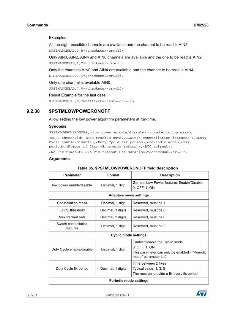
Commands UM2523
68/231 UM2523 Rev 1
Examples:
All the eight possible channels are available and the channel to be read is AIN5:
$PSTMADCREAD,0,5*<checksum><cr><lf>
Only AIN0, AIN2, AIN4 and AIN6 channels are available and the one to be read is AIN2:
$PSTMADCREAD,1,2*<checksum><cr><lf>
Only the channels AIN0 and AIN4 are available and the channel to be read is AIN4:
$PSTMADCREAD,3,4*<checksum><cr><lf>
Only one channel is available AIN0:
$PSTMADCREAD,7,0*<checksum><cr><lf>
Result Example for the last case:
$PSTMADCREAD,0,760*4f*<checksum><cr><lf>
9.2.38 $PSTMLOWPOWERONOFF
Allow setting the low power algorithm parameters at run-time.
Synopsis:
$PSTMLOWPOWERONOFF,<low power enable/disable>,<constellation mask>,<EHPE threshold>,<Max tracked sats>,<Switch constellation features >,<Duty Cycle enable/disable>,<Duty Cycle fix period>,<Periodic mode>,<Fix period>,<Number of fix>,<Ephemeris refresh>,<RTC refresh>,
<No Fix timeout>,<No Fix timeout Off duration>*<checksum><cr><lf>
Arguments:
Table 35. $PSTMLOWPOWERONOFF field description
Parameter Format Description
low power enable/disable Decimal, 1 digitGeneral Low Power features Enable/Disable
0: OFF, 1: ON
Adaptive mode settings
Constellation mask Decimal, 1 digit Reserved, must be 1
EHPE threshold Decimal, 3 digits Reserved, must be 0
Max tracked sats Decimal, 2 digits Reserved, must be 0
Switch constellation features
Decimal, 1 digit Reserved, must be 0
Cyclic mode settings
Duty Cycle enable/disable Decimal, 1 digit
Enable/Disable the Cyclic mode
0: OFF, 1: ON
This parameter can only be enabled if “Periodic mode” parameter is 0
Duty Cycle fix period Decimal, 1 digits
Time between 2 fixes
Typical value: 1, 3, 5
The receiver provide a fix every fix period
Periodic mode settings

UM2523 Rev 1 69/231
UM2523 Commands
230
Results:
If the command is executed with success the following message is sent:
$PSTMLOWPOWERON,<EHPE threshold>,<Max tracked sats>,<Switch constellation features >, <Duty Cycle enable>, <Duty Cycle fix period>, <Periodic mode>, <Fix period>, <Number of fix>, <Ephemeris refresh>, <RTC refresh>, <No Fix timeout>, <No Fix timeout Off duration>*<checksum><cr><lf>
Arguments:
Same description as reported in the previous table.
9.2.39 $PSTMCRCCHECK
Evaluates the Cyclic Redundancy Check (CRC-32bits) of the GNSS firmware and boot code memory areas and compare it with the factory stored CRC value.
Synopsis:
$PSTMCRCCHECK,<type>,<par1>,<par2>,<par3>*<checksum><cr><lf>
Arguments:
Periodic mode Decimal, 1 digit
Setup Active or Standby periodic mode
0: OFF
1: Active Periodic mode
3: Standby Periodic mode
7: Standby Periodic mode and FixOnDemand triggered by WakeUp pin. This parameter can only be different from 0 if “Duty Cycle enable/disable” parameter is 0.
FixPeriod Decimal, 5 digitsInterval between two fixes [s]. 0 means no periodic fix is required.
FixOnTime Decimal, 2 digits Number of fixes reported for each interval
Ephemeris refresh Decimal, 1 digitEnable/Disable the refresh of ephemeris data
0: OFF, 1: ON
RTC calibration Decimal, 1 digitEnable/Disable the RTC calibration
0: OFF, 1: ON
NoFixCnt Decimal, 2 digits Time to declare fix loss [s] in HOT conditions
NoFixOff Decimal, 2 digitsPeriod of off period after a fix loss [s]. 0 means the counter is not active. The fix retry will be based on FixPeriod.
Table 35. $PSTMLOWPOWERONOFF field description (continued)
Parameter Format Description

Commands UM2523
70/231 UM2523 Rev 1
Results:
The $PSTMCRCCHECK message is returned
Examples:
Note: All input parameters are optional. If command is sent with no input parameters the CRC evaluation and comparison is performed including the boot code area and using the default hard coded location to retrieve base address, size and stored CRC. In such case the command response will be:
$PSTMCRCCHECK,<result>*<checksum><cr><lf>
Note: Response message may include or not details about boot code area according to bit1 status of first input parameter.
9.2.40 $PSTMNMEAREQUEST
Send a set of NMEA messages according to the input message list as specified in the FW Configuration document.
Synopsis:
$PSTMNMEAREQUEST,<msglist_l>,<msglist_h>*<checksum><cr><lf>
Arguments:
Table 36. $PSTMCRCCHECK command field description
Parameter Format Description
type Decimal, 1 digit
Command configuration bitmask.
Bit0: defines the meaning of input parameters (par1, par2 and par3)
– 0 = input parameters represent the memory addresses where the value is stored.
– 1 = input parameters represent the value for the CRC evaluation and compare.
Bit1: indicates if boot code should be included or not in the CRC evaluation.
– 0 = boot code is included
– 1 = boot code is excluded by CRC evaluation.
Bit2: defines the response message format.
– 0 = short response message
– 1 = detailed response message
par1 Hexadecimal, 1 digitGNSS firmware base address (it could be an address or a value according to bit0 of first parameter)
par2 Hexadecimal, 1 Digit GNSS firmware size (it could be an address or a value according to bit0 of first parameter)
par3 Hexadecimal, 1 Digit GNSS firmware stored CRC (it could be an address or a value according to bit0 of first parameter)

UM2523 Rev 1 71/231
UM2523 Commands
230
Results:
A set of NMEA messages is sent according to the input message list.
Note: The order of NMEA messages in the message list is the same as for the periodic NMEA output messages.
9.2.41 $PSTMFORCESTANDBY
Force the platform to go in standby mode.
Note: This command is not implemented in 3.7.x version of the software.
Synopsis:
$PSTMFORCESTANDBY,<duration>*<checksum><cr><lf>
Arguments:
Results:
In case of no errors, the $PSTMFORCESTANDBYOK message is returned
In case of errors, the error message $PSTMFORCESTANDBYERROR is returned
9.2.42 $PSTMIONOPARAMS
Uploads a specific iono packet into the Teseo NVM. The uploaded iono packet will be retained until a new iono packet for the same constellation is successfully uploaded or downloaded from the navigation message.
Note: This command is not implemented in 3.x.y version of the software.
Synopsis: when sat_type = 0
$PSTMIONOPARAMS,<sat_type=0>,1,<A0>,<A1>,<A2>,<A3>,<B0>,<B1>,<B2>,<B3>*<checksum><cr><lf>
Table 37. $PSTMNMEAREQUEST field description
Parameter Format Description
msglist_l Hexadecimal, 1 Digit
First 32 bits of 64 bits message list (low).
Each bit is used to enable/disable a specific message.
0 = disabled
1 = enabled
msglist_h Hexadecimal, 1 Digit
Second 32 bits of 64 bits message list (high).
Each bit is used to enable/disable a specific message.
0 = disabled
1 = enabled
Table 38. $PSTMFORCESTANDBY field description
Parameter Format Description
duration Decimal, 5 digits Duration of the standby time in seconds

Commands UM2523
72/231 UM2523 Rev 1
Synopsis: when sat_type = 1
$PSTMIONOPARAMS,<sat_type=1>,1,<ai0>,<ai1>,<ai2>,<Region1>,<Region2>,<Region3>,<Region4>,<Region5>*<checksum><cr><lf>
Arguments:
9.2.43 $PSTMSETTHTRK
Configures the CN0 and Angle Elevation Mask thresholds for tracking. This command changes these parameters at run-time and no reset is required. In case of reset tracking CN0 and Angle Elevation Mask are restored to default value.
Synopsis:
$PSTMSETTHTRK,<cn0>,<el>*<checksum><cr><lf>
Arguments:
Results:
In case of no errors, the $PSTMSETTHTRKOK message is returned
In case of errors, the error message $PSTMSETTHTRKERROR is returned
Table 39. $PSTMIONOPARAMS field description
Parameter Format Description
sat_type Decimal, 1 digits
1 is for GPS
3 is Reserved
7 for BeiDou
A0,A1,A2,A3 Decimal, 3 digits
These parameters are used only if sat_type=1 or 7
Iono parameters, raw integer values as from Navigation Messages.
B0,B1,B2,B3 Decimal, 3 digits
These parameters are used only if sat_type=1 or 7
Iono parameters, raw integer values as from Navigation Messages.
ai0,ai1,ai2 Decimal, 3 digits
These parameters are used only if sat_type=3
Iono parameters, raw integer values as from Navigation Messages.
Region1, Region2, Region3, Region4,
Region5Binary Reserved
Table 40. $PSTMCFGSETTHTRK field description
Parameter Format Description
cn0 Decimal Tracking CN0 threshold as dB
el Double Tracking elevation mask angle as degree

UM2523 Rev 1 73/231
UM2523 Commands
230
9.2.44 $PSTMSETTHPOS
Configures the CN0 and Angle Elevation Mask thresholds for positioning. This command changes these parameters at run-time and no reset is required. In case of reset positioning CN0 and Angle Elevation Mask are restored to default value.
Synopsis:
$PSTMSETTHPOS,<cn0>,<el>*<checksum><cr><lf>
Arguments:
Results:
In case of no errors, the $PSTMSETTHPOSOK message is returned
In case of errors, the error message $PSTMSETTHPOSERROR is returned
9.3 ST system configuration commands
The GNSS Software utilizes a “Configuration Data Block” that holds the working parameters for the system. The parameters can be set, read or stored (in NVM) using the system configuration commands: $PSTMSETPAR, $PSTMGETPAR and $PSTMSAVEPAR. There is also a command to restore the factory setting parameters: $PSTMRESTOREPAR.
At run-time it could be possible to have up to three different configuration blocks:
Current configuration: it is placed in the RAM memory and it includes the current configuration of each parameter. This configuration block can be modified with the $PSTMSETPAR command. The $PSTMSAVEPAR command stores the current configuration data block into the NVM memory. At startup the current configuration block is loaded from NVM (if a stored data block is available) or it is loaded from the default one embedded in the code (factory settings).
Default configuration: it is generally placed in the flash/rom memory. It includes the factory setting for each parameter. This configuration is used at system startup if there is no configuration data into the NVM memory.
NVM stored configuration: it is available in the NVM backup memory as soon as the $PSTMSAVEPAR command is executed. It includes all parameters modified and stored by the user. At system startup the SW configuration management checks if a valid configuration block is available in the NVM backup memory. In case the stored configuration is available, it will be used for system configuration. If not available the default setting will be used.
Note: Other “Configuration Data Block” parameters not documented in this manual must be considered as RESERVED and must not be modified. Modifying any other parameter intentionally or unintentionally may stop the system from working and/or degrade the system performance.
Table 41. $PSTMCFGSETTHPOS field description
Parameter Format Description
cn0 Decimal Positioning CN0 threshold as dB
el Double Positioning elevation mask angle as degree

Commands UM2523
74/231 UM2523 Rev 1
9.3.1 $PSTMSETPAR
This command sets the defined parameter (indicated by “ID”) to the value provided as “param_value” in the commands parameter.
Synopsis:
$PSTMSETPAR,<ConfigBlock><ID>,<param_value>[,<mode>]*<checksum><cr><lf>
Arguments:
Results:
In case of no errors, the $PSTMSETPAROK message is returned
In case of errors, the error message $PSTMSETPARERROR is returned
Example:
Issuing the command:
$PSTMSETPAR,1121,10*<checksum><cr><lf>
You could have this answer:
$PSTMSETPAROK,1121*<checksum><cr><lf>
Note: The configuration block parameter is ignored by the “SET” command because only the current configuration, stored in the RAM memory, can be written. It is used only to keep the
Table 42. $PSTMSETPAR field description
Parameter Format Description
ConfigBlock Decimal,1 digit
Indicates one of the configuration blocks:
1=Current Configuration,
2 = Default Configuration,
3 = NVM Stored configuration.
ID Decimal, 3 digitsID - Identifier
(see Configuration Data Block as described in FW Configuration document)
param_value 1 up to 80 bytesParameter to be set, see “Allowed values” as described in FW Configuration document.
mode Decimal, 1 digit
This parameter is optional. It allows to perform bit-to-bit “OR” or “AND” operations between the selected parameter in the configuration block and the param_value in input.
It has the following meaning:
0: the parameter in the configuration block is overwritten by the param_value. This is the default action as in the case mode is omitted.
1: the parameter in the configuration block is the result of bit-to-bit “OR” between old value and the param_value.This is useful for bit mask setting.
2: the parameter in the configuration block is the result of bit-to-bit “AND” between old value and NOT(param_value). This is useful for bit mask resettimg.

UM2523 Rev 1 75/231
UM2523 Commands
230
same syntax as for the “GET” command. The configuration block stored in NVM will be overwritten by the current configuration after the $PSTMSAVEPAR command.
Note: There is no comma and no space between ConfigBlock and ID parameters.
Note: The input param_value must be expressed in hexadecimal format without “0x” prefix for any integer value except DOP configuration. It must be decimal for any not integer value and DOP setting.
9.3.2 $PSTMGETPAR
This command reads the defined parameter (indicated by “ID”) from the “Configuration Data Block” and returns it as a specific message.
Synopsis:
$PSTMGETPAR,<ConfigBlock><ID>*<checksum><cr><lf>
Arguments:
Results:
In case of no errors, $PSTMSETPAR message is sent
In case of errors, the error message $PSTMGETPARERROR is returned
Example:
Issuing the command:
$PSTMGETPAR,1403*<checksum><cr><lf>
You could have this answer:
$PSTMSET,1403,15,12,12,18*<checksum><cr><lf>
Note: There is no comma and no space between ConfigBlock and ID parameters.
Note: In case of no errors the answer is deliberately $PSTMSET and not $PSTMGET.
Note: If the parameter ID is “000” all the configuration block is printed out using one message for each parameter. The message syntax is the same as reported above.
9.3.3 $PSTMSAVEPAR
Save current configuration data block into the backup memory.
Synopsis:
$PSTMSAVEPAR*<checksum><cr><lf>
Arguments:
Table 43. $PSTMGETPAR field description
Parameter Format Description
ConfigBlock Decima1, 1 digit
Indicates one of configuration blocks:
1 = Current Configuration,
2 = Default Configuration,
3 = NVM Stored configuration.
ID Decimal, 3 digitsID - Identifier
(see Configuration Data Block)

Commands UM2523
76/231 UM2523 Rev 1
None.
Results:
The current configuration data block, including changed parameters, will be stored into the backup memory (NVM).
In case of no errors, the $PSTMSAVEPAROK message is returned
In case of errors, the error message $PSTMSAVEPARERROR is returned
Note: The factory setting parameters can be restored using the $PSTMRESTOREPAR command.
Example:
$PSTMSAVEPAR*<checksum><cr><lf>
9.3.4 $PSTMRESTOREPAR
Restore the factory setting parameters. The configuration data block stored in NVM, if present, will be invalidated. Any changed parameter will be lost.
Synopsis:
$PSTMRESTOREPAR*<checksum><cr><lf>
Arguments:
None.
Results:
The factory setting parameters will be restored and the configuration block in the backup memory will be lost. A system reboot is needed to complete the factory reset restoring and to get system working with default setting.
In case of no errors, the $PSTMRESTOREPAROK message is returned
In case of errors, the error message $PSTMRESTOREPARERROR is returned
Example:
$PSTMRESTOREPAR*<checksum><cr><lf>
9.3.5 $PSTMCFGPORT
Configure a general-purpose port for NMEA or RTCM purpose.
Synopsis:
$PSTMCFGPORT,<port_type>,<protocol_type>,<par_1>,<par_2>,…,<par_N>*<checksum><cr><lf>
Arguments:

UM2523 Rev 1 77/231
UM2523 Commands
230
Results:
One or more parameters of swconfig are set according to the command parameters. In case of no errors, the following message is returned
In case of no errors, the $PSTMCFGPORTOK message is returned
In case of errors, the error message $PSTMCFGPORTERROR is returned
9.3.6 $PSTMCFGPORT on UART
Arguments:
Table 44. $PSTMCFGPORT field description
Parameter Format Description
port_type Decimal, 1 Digit
Select the port type:
0 = UART
1 = I2C
protocol_type Decimal, 1 Digit
Select the protocol type:
0 = NMEA
1 = Reserved
2 = Reserved
3 = RTCM
par_1 … par_N IntegerParameters list according to the command type
Specification (see below).
Table 45. $PSTMCFGPORT field description when port_type is UART
Parameter Format Description
portnumb From 0 to 255 UART GPIO ID (Linearly addressed)
baudrate Integer
The port baud rate. Allowed values are:
300,
600,
1200,
2400,
4800,
9600,
14400,
19200,
38400,
57600,
115200,
230400,
460800,
921600

Commands UM2523
78/231 UM2523 Rev 1
9.3.7 $PSTMCFGPORT on I2C
Arguments:
9.3.8 $PSTMCFGANTSENS
Configure the Antenna Sensing.
Synopsis:
$PSTMCFGANTSENS,<sens_type>,<periodicmsg>,<switchcap>,<switchgpioid>,<switchgpiocfg>,<par_1>,<par_2>,...,<par_N>*<checksum><cr><lf>
Arguments:
Table 46. $PSTMCFGPORT field description when port_type is I2C
Parameter Format Description
slaveaddr Hexadecimal, 2Bytes The I2C slave address
mode Decimal, 1 digit
0 = Speed mode STANDARD
1 = Speed mode FAST
2 = Speed mode HS
Table 47. $PSTMCFGANTSENS field description
Parameter Format Description
sens_type Decimal, 1 Digit
Select the port type:
0 = OFF
1 = RF
2 = ADC
3 = GPIO
periodicmsg Decimal, 1 digit
0 = Periodic antenna related messages are disabled.
1 = Periodic antenna related messages are enabled.
switchcap Decimal, 1 digit0 = Antenna switching is disabled.
1 = Antenna switching is enabled.
switchgpioid From 0 to 255ANT_SWITCH_CTRL port ID (Linearly addressed): currently unused.
switchgpiocfg Decimal, 1 digit
ANT_SWITCH_CTRL configuration:
0 = Default,
1 = Alternate A
2 = Alternate B
3 = Alternate C
par_1 … par_N IntegerParameters list according to the command type specification (see below).

UM2523 Rev 1 79/231
UM2523 Commands
230
Results:
One or more parameters of swconfig are set according to the command parameters. In case of no errors, the following message is returned
In case of no errors, the $PSTMCFGANTSENSOK message is returned
In case of errors, the error message $PSTMCFGANTSENSERROR is returned
9.3.9 $PSTMCFGANTSENS on RF
No additional parameters are required when sensing type is RF.
9.3.10 $PSTMCFGANTSENS on ADC
Arguments:
9.3.11 $PSTMCFGANTSENS on GPIO
Arguments:
Table 48. $PSTMCFGANTSENS field description on sensing on ADC
Parameter Format Description
chidAny combination with
two bits high
ADC channel input mask. The bit position represents the ADC channel. The selected channel must have the corresponding bit enabled in the mask.
Any combination of couples of channels is allowed only for STA8090EXG. For all other packages default value, must be used: 0x3.
clkdiv From 0 to 255 Clk divisor factor to configure ADC sampling rate.
min_thr Integer < 63 Minimum Threshold value (mV).
max_thr Integer > 210 Maximum Threshold value (mV).
Table 49. $PSTMCFGANTSENS field description on sensing on GPIO
Parameter Format Description
digon_gpio_id From 0 to 255ANT_DIG_ON port ID (Linearly addressed): currently unused.
digon_gpio_cfg Decimal, 1 digit
ANT_DIG_ON port configuration:
0 = Default,
1 = Alternate A
2 = Alternate B
3 = Alternate C
dig_short_gpio_id From 0 to 255EXT_ANT_DIG_SHORT port ID (Linearly addressed): currently unused.
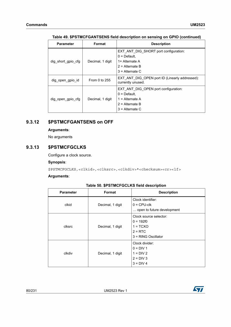
Commands UM2523
80/231 UM2523 Rev 1
9.3.12 $PSTMCFGANTSENS on OFF
Arguments:
No arguments
9.3.13 $PSTMCFGCLKS
Configure a clock source.
Synopsis:
$PSTMCFGCLKS,<clkid>,<clksrc>,<clkdiv>*<checksum><cr><lf>
Arguments:
dig_short_gpio_cfg Decimal, 1 digit
EXT_ANT_DIG_SHORT port configuration:
0 = Default,
1= Alternate A
2 = Alternate B
3 = Alternate C
dig_open_gpio_id From 0 to 255EXT_ANT_DIG_OPEN port ID (Linearly addressed): currently unused.
dig_open_gpio_cfg Decimal, 1 digit
EXT_ANT_DIG_OPEN port configuration:
0 = Default,
1 = Alternate A
2 = Alternate B
3 = Alternate C
Table 49. $PSTMCFGANTSENS field description on sensing on GPIO (continued)
Parameter Format Description
Table 50. $PSTMCFGCLKS field description
Parameter Format Description
clkid Decimal, 1 digit
Clock identifier:
0 = CPU-clk
… open to future development
clksrc Decimal, 1 digit
Clock source selector:
0 = 192f0
1 = TCXO
2 = RTC
3 = RING Oscillator
clkdiv Decimal, 1 digit
Clock divider:
0 = DIV 1
1 = DIV 2
2 = DIV 3
3 = DIV 4

UM2523 Rev 1 81/231
UM2523 Commands
230
Results:
One or more parameters of swconfig are set according to the command parameters. In case of no errors, the following message is returned
In case of no errors, the $PSTMCFGCLKSOK message is returned
In case of errors, the error message $PSTMCFGCLKSERROR is returned
9.3.14 $PSTMCFGMSGL
Configure the Message List.
Synopsis:
$PSTMCFGMSGL,<listid>,<rate>,<listlow>,<listhigh>*<checksum><cr><lf>
Arguments:
Results:
One or more parameters of swconfig are set according to the command parameters. In case of no errors, the following message is returned
In case of no errors, the $PSTMCFGMSGLOK message is returned
In case of errors, the error message $PSTMCFGMSGLERROR is returned
9.3.15 $PSTMCFGGNSS
Configure the GNSS Algorithm.
Synopsis:
$PSTMCFGGNSS,<trkcn0>,<poscn0>,<trkmskang>,<posmskang>,<NCOcntr>,<NCOmin>,<NCOmax>*<checksum><cr><lf>
Arguments:
Table 51. $PSTMCFGMSGL field description
Parameter Format Description
listid Decimal, 1 digit
List selector:
0 = NMEA list 0
1 = NMEA list 1
2 = NMEA list 2
rate From 0 to 255 Message list rate scaler
listlow Hexadecimal, 8 digits Please refer to CDB 201 table in case of NMEA
listhigh Hexadecimal, 8 digits Please refer to CDB 228 table in case of NMEA

Commands UM2523
82/231 UM2523 Rev 1
Results:
One or more parameters of swconfig are set according to the command parameters. In case of no errors, the following message is returned
In case of no errors, the $PSTMCFGGNSSOK message is returned
In case of errors, the error message $PSTMCFGGNSSERROR is returned
9.3.16 $PSTMCFGSBAS
Configure the SBAS Algorithm.
Synopsis:
$PSTMCFGSBAS,<enengine>,<enreport>,<enautosearch>,<numofsats>,<sat_1prnid>,<sat_1long>,<sat_1longsens>,<sat_1sbasserv>,<sat_1default>,...,>,<sat_Mprnid>,<sat_Mlong>,<sat_Mlongsens>,<sat_Msbasserv>,<sat_Mdefault>,<par_1>,<par_2>,...,<par_N>*<checksum><cr><lf>
Arguments:
Table 52. $PSTMCFGGNSS field description
Parameter Format Description
trkcn0 From 0 to 255Minimum CN0 [dB] at which satellite can be tracked
poscn0 From 0 to 255Minimum CN0 [dB] at which satellite can be tracked for positioning solution
trkmskang From 0 to 255Minimum elevation angle at which satellite can be tracked
posmskang From 0 to 255Minimum elevation angle at which satellite can be tracked for positioning solution
NCOcntr From 0 to 255 NCO center value
NCOmin From 0 to 255 NCO range minimum value
NCOmax From 0 to 255 NCO range maximum value
Table 53. $PSTMCFGSBAS field description
Parameter Format Description
enengine Decimal, 1 digit
Enable SBAS engine switch:
0 = Disabled
1 = Enabled
enreport Decimal, 1 digit
Enable satellite report in GSV message:
0 = Disabled
1 = Enabled
enautosearch Decimal, 1 digit
Enable autosearch switch:
0 = Disabled
1 = Enabled

UM2523 Rev 1 83/231
UM2523 Commands
230
Note: The last 5 parameters will be repeated N times, where N is the number of satellites the user has chosen.
autosearchmask Hexadecimal, 8 digitsAllow enabling/disabling the SBAS satellites to be searched by the auto search procedure
dectimeout From 0 to 255
The time the autosearch waits to try to decode the current PRN
Note: expressed in seconds. This value is ignored if enautosearch is 0
diftimeout From 0 to 255
The time the autosearch waits
before changing the prn when the current SBAS sat is not more
decoded
Note: expressed in seconds. This value is ignored if enautosearch is 0
nextsattimeout From 0 to 255
The time the autosearch waits to try to acquire and tracking new SBAS satellite using the searching channel
Note: expressed in seconds. This value is ignored if enautosearch is 0
nextsesstimeout From 0 to 255
The time the autosearch waits before starting a new searching session using the searching channel
Note: expressed in seconds. This value is ignored if enautosearch is 0
numofsats (N) From 0 to 255Number of SBAS satellites.
Note that following configuration settings will be repeated “numofsat” times
satN_prnid Integer SBAS PRN configuration for satellite 1
satN_long From 0 to 255 Longitude for satellite 1
satN_longsens Decimal, 1 digit
Longitude sense for satellite 1
0 = EAST
1 = WEST
satN_sbasserv Decimal, 1 digit
SBAS service for satellite 1
0 = WAAS
1 = EGNOS
2 = MSAS
3 = GAGAN
satN_default Decimal, 1 digit
Select if satellite 1 is default or not
0 = Not default
1 = Default
Table 53. $PSTMCFGSBAS field description (continued)
Parameter Format Description

Commands UM2523
84/231 UM2523 Rev 1
Results:
One or more parameters of swconfig are set according to the command parameters. In case of no errors, the following message is returned
In case of no errors, the $PSTMCFGSBASOK message is returned
In case of errors, the error message $PSTMCFGSBASERROR is returned
Parameters when auto-search is enabled.
9.3.17 $PSTMCFGLPA
Configure the Low Power Algorithm.
Synopsis:
$PSTMCFGLPA,<en_lpa>,<feat>,<fix_period>,<fix_on_time>,<no_fix_cnt>,<no_fix_cnt2>,<no_fix_off>,<adaptive_feat>,<adaptive_duty_cicle>,<ehpe_th>,<num_of_sat>,<duty_off>,<const_type>*<checksum><cr><lf>
Arguments:
Table 54. $PSTMCFGSBAS field description when auto-search is enabled
Parameter Format Description
Satellite-Enable-
maskInteger
Enable/disable satellites to be searched by the autosearch procedure.
Autosearch-
decoding-timeoutInteger
Set the timeout the autosearch waits to try to decode the current PRN
Autosearch-differentialtimeout
Integer
Set the timeout the autosearch waits
before changing the PRN when the current
SBAS satellite is no more decoded
Autosearch-searching-timeout-next-satellite
IntegerSet the timeout the auto-search waits to try to acquire and tracking new SBAS
satellite using the searching channel
Autosearch-searching-timeout-next-session
Integer
Set the timeout the auto-search waits
before starting a new searching session
using the searching channel
Table 55. $PSTMCFGLPA field description
Parameter Format Description
en_lpa unsigned, 1 bytes
Enable Low Power Algorithm
0 = LPA Disabled
1 = LPA Enabled.
feat unsigned, 1 bytes
Low Power Algorithm feature
0 = Periodic mode disabled
1 = Active Periodic mode
2 = RESERVED
3 = Standby Periodic mode
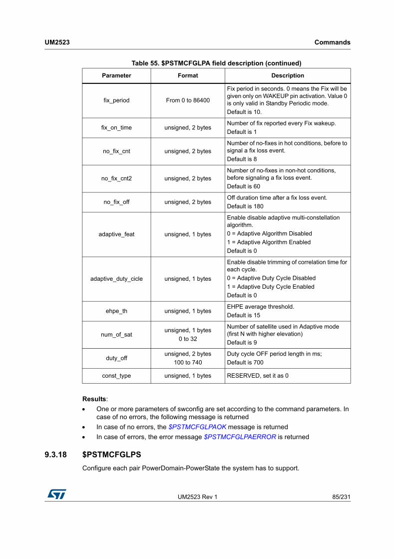
UM2523 Rev 1 85/231
UM2523 Commands
230
Results:
One or more parameters of swconfig are set according to the command parameters. In case of no errors, the following message is returned
In case of no errors, the $PSTMCFGLPAOK message is returned
In case of errors, the error message $PSTMCFGLPAERROR is returned
9.3.18 $PSTMCFGLPS
Configure each pair PowerDomain-PowerState the system has to support.
fix_period From 0 to 86400
Fix period in seconds. 0 means the Fix will be given only on WAKEUP pin activation. Value 0 is only valid in Standby Periodic mode.
Default is 10.
fix_on_time unsigned, 2 bytesNumber of fix reported every Fix wakeup.
Default is 1
no_fix_cnt unsigned, 2 bytesNumber of no-fixes in hot conditions, before to signal a fix loss event.
Default is 8
no_fix_cnt2 unsigned, 2 bytesNumber of no-fixes in non-hot conditions, before signaling a fix loss event.
Default is 60
no_fix_off unsigned, 2 bytesOff duration time after a fix loss event.
Default is 180
adaptive_feat unsigned, 1 bytes
Enable disable adaptive multi-constellation algorithm.
0 = Adaptive Algorithm Disabled
1 = Adaptive Algorithm Enabled
Default is 0
adaptive_duty_cicle unsigned, 1 bytes
Enable disable trimming of correlation time for each cycle.
0 = Adaptive Duty Cycle Disabled
1 = Adaptive Duty Cycle Enabled
Default is 0
ehpe_th unsigned, 1 bytesEHPE average threshold.
Default is 15
num_of_satunsigned, 1 bytes
0 to 32
Number of satellite used in Adaptive mode (first N with higher elevation)
Default is 9
duty_offunsigned, 2 bytes
100 to 740
Duty cycle OFF period length in ms;
Default is 700
const_type unsigned, 1 bytes RESERVED, set it as 0
Table 55. $PSTMCFGLPA field description (continued)
Parameter Format Description

Commands UM2523
86/231 UM2523 Rev 1
Synopsis:
$PSTMCFGLPS,<numoflps>,<pd1>,<ps1>,<voltage1>,<pd2>,<ps2>,<voltage2>,...*<checksum><cr><lf>
Arguments:
Results:
One or more parameters of swconfig are set according to the command parameters. In case of no errors, the following message is returned
In case of no errors, the $PSTMCFGLPSOK message is returned
In case of errors, the error message $PSTMCFGLPSERROR is returned
9.3.19 $PSTMCFGAJM
Configure the Anti-Jamming Algorithm.
Synopsis:
$PSTMCFGAJM,<gpsmode>,<glonassmode>*<checksum><cr><lf>
Arguments:
Table 56. $PSTMCFGLPS field description
Parameter Format Description
numoflps DecimalThe number of pair Power State – Power Domain to be configured. Note that next parameters will be repeated ‘numodlps’ times.
pd Decimal, 1 digit
The Power Domain ID to configure:
0 = SMPS
1 = LDO1
2 = LDO2
3 = BKLDO
ps Decimal, 1 digit
The Power State to configure
0 = Low Frequency;
1 = High Frequency
voltage Decimal, 1 digit
The pair voltage value which will be set
0 = OFF
1 = 1.0 V
(means 1.8V if LDO is configured as 1.8 V, means ON if domain has ON/OFF only)
2 = 1.1 V
(means 1.8V if LDO is configured as 1.8 V. RESERVED if domain has ON/OFF only)
3 = 1.2 V
(means 1.8V if LDO is configured as 1.8 V.
RESERVED if domain has ON/OFF only)

UM2523 Rev 1 87/231
UM2523 Commands
230
Results:
One or more parameters of swconfig are set according to the command parameters. In case of no errors, the following message is returned
In case of no errors, the $PSTMCFGAJMOK message is returned
In case of errors, the error message $PSTMCFGAJMERROR is returned
9.3.20 $PSTMCFGODO
Configure the Odometer.
This command is implemented and supported only in Binary Image 4.5.8 and later.
Synopsis:
$PSTMCFGODO,<en>,<enmsg>,<alarm>*<checksum><cr><lf>
Arguments:
Results:
One or more parameters of swconfig are set according to the command parameters. In case of no errors, the following message is returned
In case of no errors, the $PSTMCFGODOOK message is returned
In case of errors, the error message $PSTMCFGODOERROR is returned
Table 57. $PSTMCFGAJM field description
Parameter Format Description
gpsmode Decimal, 1 digit
Notch filter on GPS path:
0 = Disable
1 = Normal Mode
2 = Auto Mode
glonassmode Decimal, 1 digit
Notch filter on GLONASS path:
0 = Disable
1 = Normal Mode
2 = Auto Mode
Table 58. $PSTMCFGODO field description
Parameter Format Description
en Decimal, 1 digit
Enable/Disable the odometer:
0 = Odometer disabled
1 = Odometer enabled
enmsg Decimal, 1 digit
Enable/Disable odometer related periodic messages:
0 = Periodic message disabled
1 = Periodic message enabled
alarm 0 to 65535Distance travelled between two NMEA messages

Commands UM2523
88/231 UM2523 Rev 1
9.3.21 $PSTMCFGGEOFENCE
Allows to configure Geofencing feature enabling circles and choosing tolerance.
This command is implemented and supported only in Binary Image 4.5.8 and later.
Synopsis:
$PSTMCFGGEOFENCE,<en>,<tol>*<checksum><cr><lf>
Arguments:
Results:
One or more parameters of swconfig are set according to the command parameters. In case of no errors, the following message is returned
In case of no errors, the $PSTMCFGGEOFENCEOK message is returned
In case of errors, the error message $PSTMCFGGEOFENCEERROR is returned
9.3.22 $PSTMCFGGEOCIR
Allows to configure a circle of geofencing feature.
This command is implemented and supported only in Binary Image 4.5.8 and later.
Synopsis:
$PSTMCFGGEOCIR,<circleid>,<en>,<lat>,<lon>,<rad>*<checksum><cr><lf>
Arguments:
Table 59. $PSTMCFGGEOFENCE field description
Parameter Format Description
en Decimal, 1 digit
Enable/Disable the geofencing:
0 = Geo fencing disabled
1 = Geo fencing enabled
tol Decimal, 1 digit
Tolerance:
0 = none
1 = level 1
2 = level 2
3 = level 3
Table 60. $PSTMCFGGEOCIR field description
Parameter Format Description
circleid Decimal, 1 digitThe circle ID
From 0 to 7
en Boolean
Enable disable the circle
0 = Disable,
1 = Enable
lat Double N-th circle latitude

UM2523 Rev 1 89/231
UM2523 Commands
230
Results:
One or more parameters of swconfig are set according to the command parameters. In case of no errors, the following message is returned
In case of no errors, the $PSTMCFGGEOCIROK message is returned
In case of errors, the error message $PSTMCFGGEOCIRERROR is returned
9.3.23 $PSTMCFGCONST
Allow enable/disable all the GNSS constellations.
Synopsis:
$PSTMCFGCONST,<gps>,<glonass>,0,<qzss>,<beidou<*<checksumn><cr><lf>
Arguments:
lon Double N-th circle longitude
rad Double N-th circle radius
Table 60. $PSTMCFGGEOCIR field description (continued)
Parameter Format Description
Table 61. $PSTMCFGCONST field description
Parameter Format Description
Gps Decimal, 1 digit
Allowed values:
Constellation disabled
Constellation satellites only tracked
Satellites constellation used in position evaluation
Gloanss Decimal, 1 digit
Allowed values:
Constellation disabled
Constellation satellites only tracked
Satellites constellation used in position evaluation
Reserved Decimal, 1 digit Reserved must be zero
Qzss Decimal, 1 digit
Allowed values:
Constellation disabled
Constellation satellites only tracked
Satellites constellation used in position evaluation
Beidou Decimal, 1 digit
Allowed values:
Constellation disabled
Constellation satellites only tracked
Satellites constellation used in position evaluation

Commands UM2523
90/231 UM2523 Rev 1
Results:
One or more parameters of swconfig are set according to the command parameters
In case of no errors, the $PSTMCFGCONSTOK message is returned
In case of errors, the $PSTMCFGCONSTERROR error message is returned
9.3.24 $PSTMCFGTHGNSS
Configures threshold related to GNSS algorithm.
Synopsis:
$PSTMCFGTHGNSS,<trkcn0>,<poscn0>,<trkmaskangle>,<posmaskangle>*<checksum><cr><lf>
Arguments:
Results:
If the command syntax is correct and parameters are correctly set, the device return the $PSTMCFGTHGNSSOK confirmation message
In case of errors, the error message $PSTMCFGTHGNSSERROR is returned
9.3.25 $PSTMCFGTDATA
Configures data and time related parameters.
Synopsis:
$PSTMCFGTDATA,<gpsminweek>,<gps_max_week>,<fix_rate>,<utcdelta>*<checksum><cr><lf>
Arguments:
Table 62. $PSTMCFGTHGNSS field description
Parameter Format Description
trkcn0 Unsigned Minimum CN0 for tracking purposes
poscn0 Unsigned Minimum CN0 for positioning purposes
trkmaskangle Unsigned Minimum angle for tracking purposes
posmaskangle Unsigned Minimum angle for positioning purposes
Table 63. $PSTMCFGTDATA field description
Parameter Format Description
gpsminweek Unsigned GPS minimum week number
gpsmaxweek Unsigned GPS maximum week number
fix_rate Double Fix rate
utc_delta Unsigned UTC delta time

UM2523 Rev 1 91/231
UM2523 Commands
230
Results:
If the command syntax is correct and parameters are correctly set, the device return the $PSTMCFGTDATAOK confirmation message
In case of errors, the $PSTMCFGTDATAERROR message, is returned
9.4 Geofencing NMEA commands
9.4.1 $PSTMGEOFENCECFG
This command configures the Geofence subsystem.
Each $PSTMGEOFENCECFG command can configure only one circle, if more circles are needed the Host has to raise more $PSTMGEOFENCECFG commands.
Geofencing subsystem is able to manage only one GPIO, therefore when more than a circle is configured to trigger a GPIO alarm, all the configurations have to specify the same GPIO with the same GPIO configuration.
This command is implemented and supported only in Binary Image 4.5.8 and later.
Synopsis:
$PSTMGEOFENCECFG,<id>,<en>,<tol>,<lat>,<lon>,<rad>*<checksum><cr><lf>
Arguments:
Results:
In case of no errors, the $PSTMGEOFENCECFGOK message is returned
In case of errors, the error message $PSTMGEOFENCECFGERROR is returned
9.4.2 $PSTMGEOFENCEREQ
This command forces the GNSS Teseo III to send a $PSTMGEOFENCESTATUS message to know the internal Geofence subsystem status.
This command is implemented and supported only in Binary Image 4.5.8 and later.
Table 64. $PSTMGEOFENCECFG field description
Parameter Format Description
id Decimal, 1 digit Circle identifier
en Decimal, 1 digit
Circle enabler:
0 = Circle not valid
1 = Circle enabled
tol Decimal, 1 digit
Sigma tolerance
1 = 68%
2 = 95%
3 = 99%
lat Double Latitude as Decimal Degrees
lon Double Longitude as Decimal Degrees
rad Double Radius as meters

Commands UM2523
92/231 UM2523 Rev 1
Synopsis:
$PSTMGEOFENCEREQ*<checksum><cr><lf>
Arguments:
No Arguments
Results:
In case of no errors, the Teseo III replies with the $PSTMGEOFENCESTATUS message
In case of errors, the error message $PSTMGEOFENCEREQERROR is returned
9.5 Odometer NMEA commands
9.5.1 $PSTMODOSTART
This command enables and resets the Odometer subsystem which begins evaluating the ground distance from the current resolved position.
This command is implemented and supported only in Binary Image 4.5.8 and later.
Synopsis:
$PSTMODOSTART*<checksum><cr><lf>
Arguments:
No arguments.
Results:
In case of no errors, the $PSTMODOSTARTOK message is returned
In case of errors, the error message $PSTMODOSTARTERROR is returned
9.5.2 $PSTMODOSTOP
This command stops the Odometer subsystem.
This command is implemented and supported only in Binary Image 4.5.8 and later.
Synopsis:
$PSTMODOSTOP*<checksum><cr><lf>
Arguments:
No arguments
Results:
In case of no errors, the $PSTMODOSTOPOK message is returned
In case of errors, the error message $PSTMODOSTOPERROR is returned
9.5.3 $PSTMODORESET
This command resets the Odometer subsystem.
This command is implemented and supported only in Binary Image 4.5.8 and later.
Synopsis:

UM2523 Rev 1 93/231
UM2523 Commands
230
$PSTMODORESET,<odo_mask>*<checksum><cr><lf>
Arguments:
Results:
In case of no errors, the $PSTMODORESETOK message is returned
In case of errors, the error message $PSTMODORESETERROR is returned
9.5.4 $PSTMODOREQ
This command requires the Odometer status. The Odometer must be enabled otherwise the request will be rejected with error.
The Odometer must be enabled otherwise the request will be rejected with error.
This command is implemented and supported only in Binary Image 4.5.8 and later.
Synopsis:
$PSTMODOREQ*<checksum><cr><lf>
Arguments:
No arguments
Results:
In case of no errors, this replies with a $PSTMODO message.
In case of errors, the error message $PSTMODOREQERROR is returned
9.6 Real Time AGNSS NMEA commands
9.6.1 $PSTMSTAGPS8PASSGEN
Request the generation of a password to access the Real-Time AGPS server to the device.
Synopsis:
$PSTMSTAGPS8PASSGEN,<time>,<Ven ID>*<checksum><cr><lf>
Arguments:
Table 65. $PSTMODORESET field description
Parameter Format Description
odo_mask Decimal
The odometers to be reset:
0 = none
1 = Odo-A
2 = Odo-B
3 = Odo-A and Odo-B
4 = Odo-Tot
5 = Odo-A and Odo-Tot
6 = Odo-B and Odo-Tot
7 = Odo-A, Odo-B and Odo-Tot

Commands UM2523
94/231 UM2523 Rev 1
Results:
ST GNSS Teseo III returns the password in the message $PSTMSTAGPS8PASSRTN.
Table 66. $PSTMSTAGPS8PASSGEN field description
Parameter Description
<time> GPS time in seconds.
<Vendor ID> Unique Vendor ID

UM2523 Rev 1 95/231
UM2523 Messages
230
10 Messages
This section contains both the standard NMEA messages and the proprietary messages delivered from any ST-GPS system. Additionally, it contains messages which result from a specific command input.
10.1 Standard NMEA messages list
10.2 ST NMEA messages list
Table 67. Standard NMEA messages list
Syntax Default Description
$--GNS ON NMEA: Global Position System Fix Data
$GPGGA ON NMEA: Global Position System Fix Data
$GPGLL OFF NMEA: Geographic Position Latitude/Longitude
$--GSA ONNMEA: GPS DOP and Active Satellites.
“GP”, “GL” and “GN” talker ID are supported according to the software configuration.
$--GSV ONNMEA: GPS Satellites in View.
“GP”, “GL” and “GN” talker ID are supported according to the software configuration.
$GPRMC ON NMEA: Recommended Minimum Specific GNSS Data
$GPVTG OFF NMEA: Track made good and ground speed
$GPZDA OFF NMEA: Time and Date
$GPGST ON NMEA: GNSS Pseudorange Noise Statistics
$--DTM OFF NMEA: Local datum offsets from reference
Table 68. ST NMEA messages list
Syntax Default Description
$PSTMDIFF OFF ST: Differential Correction Data
$PSTMPRES OFF ST: Position Residuals
$PSTMVRES OFF ST: Velocity Residuals
$PSTMPA OFF ST: Position Algorithm
$PSTMRF OFF ST: Radio Frequency
$PSTMSAT OFF ST: Satellite Information
$PSTMSBAS ON ST: Augmentation System
PSTMSBASM OFF ST; Augmentation System Message
$PSTMTIM OFF ST: System Time

Messages UM2523
96/231 UM2523 Rev 1
10.3 Changing standard NMEA messages format
By default, Standard NMEA Messages are compliant with the “NMEA 0183” Standard Rev. 3.1 dated January 2002. To change format to Rev. 4.10, issued from the “National Marine Electronics Association” in the August 2012 some system configuration commands should be issued.It is required to change the value of Configuration Data Block 122 from the default value to “4”.
$PSTMSETPAR,1122,4
$PSTMSAVEPAR
$PSTMSRR
It is possible to go back to default configuration restoring parameters or setting CDB 122 as 0xC
$PSTMSETPAR,1122,C
$PSTMSAVEPAR
$PSTMSRR
10.4 Preliminary notes about satellites’ PRN ranges
The satellite PRN is an ID used to identify satellites. In NMEA 0183 Rev 3.1, PRN was not described for new constellation. Starting from Rev 4.10 more constraints about this info have been added. Thus, PRN ranges depend on NMEA revision in use.
$PSTMTG OFF ST: Time and Number of used Satellites
$PSTMTS OFF ST: Tracked Satellite Data
$PSTMKFCOV OFF ST: Standard Deviation and Covariance
$PSTMNOTCHSTATUS OFF ST: Reports the Notch filter status.
$PSTMCPU ON ST: Reports the CPU usage and CPU speed setting.
$PSTMPPSDATA OFF ST: Reports the Pulse Per Second data.
$PSTMTRAIMUSED OFF ST: Reports the satellites used for timing correction.
$PSTMTRAIMRES OFF ST: Reports the residuals for used satellites.
$PSTMTRAIMREMOVED OFF ST: Reports the satellites removed by timing correction algorithm.
$PSTMLOWPOWERDATA OFF ST: Reports the status of low power algorithm
Table 68. ST NMEA messages list (continued)
Syntax Default Description
Table 69. Satellite PRNs for each NMEA version
GPS SBAS GLONASS BAIDEU QZSS GALILEO
NMEA 3.10 from 1 to 32 from 33 to 51 from 65 to 92from 141 to
172from 183 to
197from 301 to
330
NMEA 4.10 from 1 to 32 from 33 to 64 from 65 to 99 from 1 to 32 from 1 to 32 from 1 to 36

UM2523 Rev 1 97/231
UM2523 Messages
230
10.5 Standard NMEA messages specification
These messages are defined within the “NMEA 0183” Specification.
10.5.1 $--GGA
Global Positioning System Fixed data
NMEA message list bitmask (64 bits): 0000 0000 0000 0002
Synopsis for NMEA 0183 Rev 3.1 (Default):
$GPGGA,<Timestamp>,<Lat>,<N/S>,<Long>,<E/W>,<GPSQual>,<Sats>,<HDOP>,
<Alt>,<AltVal>,<GeoSep>,<GeoVal>,<DGPSAge>,<DGPSRef>*<checksum><cr><lf>
Synopsis for NMEA 0183 Rev 4.10:
$<TalkerID>GGA,<Timestamp>,<Lat>,<N/S>,<Long>,<E/W>,<GPSQual>,
<Sats>,<HDOP>,<Alt>,<AltVal>,<GeoSep>,<GeoVal>,<DGPSAge>,<DGPSRef>*
<checksum><cr><lf>
Arguments:
Table 70. $--GGA message field description
Parameter Format Description
TalkerID String, 2 characters
The talker ID (Fixed two characters).
GP: If system works in GPS only mode
GL: If system works in GLONASS only mode
GA: Reserved
BD: If system works in BEIDOU only mode
QZ: If system works in QZSS only mode
GN: If system works in multi-constellation mode.
Timestamp hhmmss.sss
UTC Time of GPS Sample:
hh: hours (Fixed two digits)
mm: minutes (Fixed two digits)
ss: seconds (Fixed two digits)
.sss: decimal fraction of seconds (Variable length)
Note that decimal fraction assumes non zero values when the fix rate is bigger than 1Hz.
Note that for Rev 4.10 this field is empty in case of invalid value
Lat DDMM.MMMMM
Latitude as degrees:
DD: Degree (Fixed two digits)
MM: Minutes (Fixed two digits)
.MMMMM: Decimal fraction of minutes (Variable)
Note that for Rev 4.10 this field is empty in case of invalid value
N/S “N” or “S”Latitude direction: North or South
Note that for Rev 4.10 this field is empty in case of invalid value

Messages UM2523
98/231 UM2523 Rev 1
Example:
$GPGGA,183417.000,04814.03970,N,01128.52205,E,0,00,99.0,495.53,M,47.6,M*53
10.5.2 $--GLL
Geographic Positioning Latitude / Longitude
NMEA message list bitmask (64 bits): 0000 0000 0010 0000
Synopsis for NMEA 0183 Rev 3.1 (Default):
$GPGLL,<Lat>,<N/S>,<Long>,<E/W>,<Timestamp>,<Status>,<mode indicator>*<checksum><cr><lf>
Synopsis for NMEA 0183 Rev 4.10:
$<TalkerID>GLL,<Lat>,<N/S>,<Long>,<E/W>,<Timestamp>,<Status>,<mode indicator>*<checksum><cr><lf>
Arguments:
Long DDMM.MMMMM
Longitude as degrees:
DD: Degree (Fixed two digits)
MM: Minutes (Fixed two digits)
.MMMMM: Decimal fraction of minutes (Variable)
Note that for Rev 4.10 this field is empty in case of invalid value
E/W “E” or “W”Longitude direction: East or West
Note that for Rev 4.10 this field is empty in case of invalid value
GPSQual Decimal, 1digit
0 = Fix not available or invalid
1 = GPS, SPS Mode, fix valid
2 = Differential GPS, SPS Mode, fix valid
6 = Estimated (dead reckoning) mode
Sats Decimal, 2 digits Satellites in use: example: 8
HDOP Decimal, 3 digits Horizontal Dilution of Precision, max: 99.0
Alt Decimal, 6 digits Height above mean sea level, max: 100000m
AltVal “M” Reference Unit for Altitude (“M” = meters)
GeoSep Decimal, 4 digits Geoidal Separation measure in “M” = meters
GeoVal “M” Reference Unit for GeoSep (“M” = meters)
DGPSAge Empty Not supported
DGPSRef Empty Not supported
ChecksumHexadecimal, 2
digitsChecksum of the message bytes without *<checksum><cr><lf> characters.
Table 70. $--GGA message field description (continued)
Parameter Format Description

UM2523 Rev 1 99/231
UM2523 Messages
230
Example:
$GPGLL,4055.04673,N,01416.54941,E,110505.000,A,A*54
10.5.3 $--GSA
GNSS DOP and Active Satellites. Satellites from different constellations are sent on separate messages.
In case of multi-constellation mode, the talker ID is always GN. If NMEA is set as Rev 3.1, it is possible to force the talker ID as GN also acting on CDB-ID 200. (See STA8089-90 Firmware Configuration document).
Table 71. $--GLL message field description
Parameter Format Description
TalkerID String, 2 characters
The talker ID (Fixed two characters).
GP: If system works in GPS only mode
GL: If system works in GLONASS only mode
GA: Reserved
BD: If system works in BEIDOU only mode
QZ: If system works in QZSS only mode
GN: If system works in multi-constellation mode.
N/S “N” or “S”Latitude direction: North or South
Note that for Rev 4.10 this field is empty in case of invalid value
Long DDMM.MMMMM
Longitude as degrees:
DD: Degree (Fixed two digits)
MM: Minutes (Fixed two digits)
.MMMMM: Decimal fraction of minutes (Variable)
Note that for Rev 4.10 this field is empty in case of invalid value
E/W “E” or “W”Longitude direction: East or West
Note that for Rev 4.10 this field is empty in case of invalid value
Timestamp hhmmss.sssUTC Time of GGL Sample, example: 160836
“.sss” is the fraction of seconds; it assumes non zero values when the fix rate is bigger than 1Hz.
Status “A” or “V” Validity of Data “A” = valid, “V” = invalid
Mode indicator “D”, “A”, “N” or “E”
Positioning system Mode Indicator:
“D” = Differential mode
“A” = Autonomous mode
“N” = data not valid
“E” = Estimated (dead reckoning) mode
checksumHexadecimal,2
digitsChecksum of the message bytes without *<checksum><cr><lf> characters.

Messages UM2523
100/231 UM2523 Rev 1
When NMEA is set as Rev 4.10 (See chapter 6.4 in this document) the talker ID could not be forced and is managed internally to be compliant with the standard. See parameter table for info about Talker ID available values.
NMEA message list bitmask (64 bits): 0000 0000 0000 0004
Synopsis for NMEA 0183 Rev 3.1 (Default):
$--GSA,<Mode>,<CurrentMode>,<SatPRN1>,...,<SatPRNN>,<PDOP>,<HDOP>,
<VDOP>*<checksum><cr><lf>
Synopsis for NMEA 0183 Rev 4.10:
$--GSA,<Mode>,<CurrentMode>,<SatPRN1>,...,<SatPRNN>,<PDOP>,<HDOP>,
<VDOP>,<SystemID>*<checksum><cr><lf>
Arguments:
Table 72. $--GSA message field description
Parameter Format Description
TalkerID String, 2 characters
The talker ID (Fixed two characters).
GP: If system works in GPS only mode
GL: If system works in GLONASS only mode
GA: Reserved
BD: If system works in BEIDOU only mode
QZ: If system works in QZSS only mode
GN: If system works in multi-constellation mode.
CurrentMode Decimal, 1 digit
Current Mode:
1 = Fix not available or invalid
2 = GPS, SPS Mode, fix valid
3 = Differential GPS, SPS Mode, fix valid
SatPRN(1 to 12)Decimal, 2 or 3
digitsSatellites list used for positioning. See Chapter 6.5 for more info about available values.
PDOP Decimal, 3 digits Position Dilution of Precision, max: 99.0
HDOP Decimal, 3 digits Horizontal Dilution of Precision, max: 99.0
VDOP Decimal, 3 digits Vertical Dilution of Precision, max: 99.0
SystemID Hexadecimal, 1 digit
The system ID of this message:
1 = GPS
2 = GLONASS
3 = Reserved
4 = BEIDOU
5 = QZSS
checksumHexadecimal, 2
digitsChecksum of the message bytes without *<checksum><cr><lf> characters.

UM2523 Rev 1 101/231
UM2523 Messages
230
Example for NMEA 0183 Rev 3.1 (Default):
$GPGSA,A,3,05,21,07,24,30,16,12,,,,,,2.4,1.9,1.5*38
Example for NMEA 0183 Rev 4.10:
$GNGSA,A,3,23,03,22,09,01,19,17,06,31,11,,,1.1,0.6,0.9,1*3E
$GNGSA,A,3,67,66,81,65,88,75,82,74,,,,, 1.1,0.6,0.9,2*3D
$GNGSA,A,3,03,05,22,08,30,16,12,,,,,, 1.1,0.6,0.9,3*32
10.5.4 $--GSV
GNSS Satellites in View.
Usually GSV messages are organized per constellation and each message carries information about up to 4 satellites in view. Thus, in certain cases, to describe all the satellites in view from a constellation more than a message is needed. This set of message is printed once per each constellation with talker ID related to described constellation.
Prior to NMEA Revision 3.1 it is possible to force the “GN” talker ID acting on CDB-ID 200 Bit 19. In such case a single set of messages is sent.
With NMEA Rev 4.10 the “GN” talker ID is forbidden in order to be compliant with the standard. Thus the module will print a set of messages for each constellation.
NMEA message list bitmask (64 bits): 0000 0000 0008 0000
Synopsis for NMEA 0183 Rev 3.1 (Default):
$--GSV,<GSVAmount>,<GSVNumber>,<TotSats>,<Sat1PRN>,<Sat1Elev>,
<Sat1Azim>,<Sat1CN0>,…,<Sat4PRN>,<Sat4Elev>,<Sat4Azim>,<Sat4CN0>*
<checksum><cr><lf>
Synopsis for NMEA 0183 Rev 4.10:
$--GSV,<GSVAmount>,<GSVNumber>,<TotSats>,<Sat1PRN>,<Sat1Elev>,
<Sat1Azim>,<Sat1CN0>,…,<Sat4PRN>,<Sat4Elev>,<Sat4Azim>,<Sat4CN0>,
<SignalID>*<checksum><cr><lf>
Arguments:
Table 73. $--GSV message field description
Parameter Format Description
TalkerID String, 2 characters
The talker ID (Fixed two characters).
GP: If system works in GPS only mode
GL: If system works in GLONASS only mode
GA: Reserved
BD: If system works in BEIDOU only mode
QZ: If system works in QZSS only mode
GN: If system works in multi-constellation mode.
GSVAmount Decimal, 1 digit Total amount of GSV messages
GSVNumber Decimal, 1 digit Continued GSV number of this message
TotSats Decimal, 2 digits Total Number of Satellites in view, max. 32
SatxPRN Decimal, 2 digitsSatellites list used for positioning. See Section 10.4 for more info about available values.

Messages UM2523
102/231 UM2523 Rev 1
Example for NMEA 0183 Rev 3.1 (Default):
$GPGSV,3,1,12,02,04,037,,05,27,125,44,06,78,051,23,07,83,021,30*7C
$GPGSV,3,2,12,10,16,067,30,12,11,119,36,16,24,301,41,21,44,175,50*73
$GPGSV,3,3,12,23,06,326,28,24,61,118,40,30,45,122,43,31,52,253,37*7C
Example for NMEA 0183 Rev 4.10:
$GPGSV,3,1,09,30,68,039,49,05,61,266,50,28,52,137,47,07,38,052,48,01*5C
$GPGSV,3,2,09,13,37,301,45,09,17,105,43,15,07,297,40,08,06,056,41,01*56
$GPGSV,3,3,09,20,,,41,,,,,,,,,,,,,01*5A
$GLGSV,2,1,06,68,86,031,43,78,78,013,46,79,51,226,43,69,33,325,38,01*43
$GLGSV,2,2,06,67,33,139,41,77,26,035,36,,,,,,,,,01*46
$GAGSV,2,1,05,08,76,129,44,02,65,057,46,30,56,205,45,07,48,311,44,06*4F
$GAGSV,2,2,05,03,22,129,40,,,,,,,,,,,,,06*7D
10.5.5 $--RMC
Recommended Minimum Specific GPS/Transit data. Time, date, position and speed data provided by the GNSS Teseo. This sentence is transmitted at intervals not exceeding 2 seconds and is always accompanied by RMB when destination way point is active.
NMEA message list bitmask (64 bits): 0000 0000 0000 0040
Synopsis for NMEA 0183 Rev 3.1 (Default):
$GPRMC,<Timestamp>,<Status>,<Lat>,<N/S>,<Long>,<E/W>,<Speed>,
<Trackgood>,<Date>,<MagVar>,<MagVarDir>,<mode>*<checksum><cr><lf>
Synopsis for NMEA 0183 Rev 4.10:
$<TalkerID>RMC,<Timestamp>,<Status>,<Lat>,<N/S>,<Long>,<E/W>,<Speed>,
<Trackgood>,<Date>,<MagVar>,<MagVarDir>,<mode>,
<Nav_status>*<checksum><cr><lf>
Arguments:
SatxElev Decimal, 2 digitsElevation of satellite x in Degree,
0 … 90
SatxAzim Decimal, 3 digitsAzimuth of satellite x in degree, ref. “North”,
000 … 359
SatxCN0 Decimal, 2 digitsCarrier to Noise Ratio for satellite x in dB,
00 … 99
SignalID Decimal, 1 digitsAn identifier to indicate the signal in use. Currently it is 1 for GPS, GLONASS, 2 for BEIDOU and QZSS 6 for GALILEO
checksumHexadecimal, 2
digitsChecksum of the message bytes without *<checksum><cr><lf> characters.
Table 73. $--GSV message field description (continued)
Parameter Format Description

UM2523 Rev 1 103/231
UM2523 Messages
230
Table 74. $--RMC message field description
Parameter Format Description
TalkerID String, 2 characters
The talker ID (Fixed two characters).
GP: If system works in GPS only mode
GL: If system works in GLONASS only mode
GA: Reserved
BD: If system works in BEIDOU only mode
QZ: If system works in QZSS only mode
GN: If system works in multi-constellation mode.
Timestamp hhmmss.sss
UTC Time of GPS Sample:
hh: hours (Fixed two digits)
mm: minutes (Fixed two digits)
ss: seconds (Fixed two digits)
.sss: decimal fraction of seconds (Variable length)
Note that decimal fraction assumes non zero values when the fix rate is bigger than 1Hz.
Note that for Rev 4.10 this field is empty in case of invalid value
Status “A” or “V”Teseo warning: “A” = valid, “V” = Warning
NOTE: “V” is reported in NO FIX conditions and “A” is reported in 2D and 3D fix conditions.
Lat DDMM.MMMMM
Latitude as degrees:
DD: Degree (Fixed two digits)
MM: Minutes (Fixed two digits)
.MMMMM: Decimal fraction of minutes (Variable)
Note that for Rev 4.10 this field is empty in case of invalid value
N/S “N” or “S”Latitude direction: North or South
Note that for Rev 4.10 this field is empty in case of invalid value
Long DDMM.MMMMM
Longitude as degrees:
DD: Degree (Fixed two digits)
MM: Minutes (Fixed two digits)
.MMMMM: Decimal fraction of minutes (Variable)
Note that for Rev 4.10 this field is empty in case of invalid value
E/W “E” or “W”Longitude direction: East or West
Note that for Rev 4.10 this field is empty in case of invalid value
Speed ddd.d Speed over ground in knots
Trackgood Decimal, 4 digits Course made good, max. 999.9
Date Decimal, 6 digits Date of Fix: ddmmyyyy
MagVar Decimal, 4 digits Magnetic Variation, max.: 090.0
MagVarDir “E” or “W” Magnetic Variation Direction

Messages UM2523
104/231 UM2523 Rev 1
Example for NMEA 0183 Rev 3.1 (Default):
$GPRMC,183417.000,V,4814.040,N,01128.522,E,0.0,0.0,170907,0.0,W*6C
Example for NMEA 0183 Rev 4.10:
$GNRMC,,V,,,,,,,,,,N,V*37
or
$GNRMC,202340.000,A,4045.53297,N,01447.20361,E,0.2,0.0,291117,,,A,C*18
10.5.6 $--VTG
Course over ground and ground speed, this message provides the actual course and speed relative to ground.
NMEA message list bitmask (64 bits): 0000 0000 0000 0010
Synopsis for NMEA 0183 Rev 3.1 (Default):
$GPVTG,<TMGT>,T,<TMGM>,M,<SoGN>,N,<SoGK>,K,D*<checksum><cr><lf>
Synopsis for NMEA 0183 Rev 4.10:
$<TalkerID>VTG,<TMGT>,T,<TMGM>,M,<SoGN>,N,<SoGK>,K,D*<checksum><cr><lf>
Arguments:
Mode “D”, “A”, “N” or “E”
Positioning system Mode Indicator:
“D” = Differential mode
“A” = Autonomous mode
“N” = data not valid
“E” = Estimated (dead reckoning) mode
Nav_status “S”, “C”, “U” or “V”
Navigational status indicator:
“S” = Safe
“C” = Caution
“U” = Unsafe
“V” = Not valid
checksumHexadecimal, 2
digitsChecksum of the message bytes without *<checksum><cr><lf> characters.
Table 74. $--RMC message field description (continued)
Parameter Format Description
Table 75. $--VTG message field description
Parameter Format Description
TalkerID String, 2 characters
The talker ID (Fixed two characters).
GP: If system works in GPS only mode
GL: If system works in GLONASS only mode
GA: Reserved
BD: If system works in BEIDOU only mode
QZ: If system works in QZSS only mode
GN: If system works in multi-constellation mode.
TMGT ddd.d in degrees Track in reference to “true” earth poles

UM2523 Rev 1 105/231
UM2523 Messages
230
Example:
$GPVTG,73.2,T,,M,0.2,N,0.4,K,D*50
10.5.7 $--ZDA
UTC, day, month and year.
NMEA message list bitmask (64 bits): 0000 0000 0100 0000
Synopsis for NMEA 0183 Rev 3.1 (Default):
$GPZDA,<Timestamp>,<Day>,<Month>,<Year>,00,00*<checksum><cr><lf>
Synopsis for NMEA 0183 Rev 4.10:
$<TalkerID>ZDA,<Timestamp>,<Day>,<Month>,<Year>,,*<checksum><cr><lf>
Arguments:
T Indicates “terrestrial”
TMGM ddd.d in degrees Track in reference to “magnetic” earth poles
M Indicates “magnetic”
SoGN ddd.d in knots Speed over Ground in knots
N Indicates “knots”
SoGK ddd.d in km/h Speed over Ground in kilometers per hour
K Indicates “kilometres”
D char
Mode indicator:
A = Autonomous mode
D= Differential mode
E= Estimated mode
checksumHexadecimal,2
digitsChecksum of the message bytes without *<checksum><cr><lf> characters
Table 75. $--VTG message field description (continued)
Parameter Format Description

Messages UM2523
106/231 UM2523 Rev 1
Example for NMEA 0183 Rev 3.1 (Default):
$GPZDA,110505.00,25,01,2013,00,00*60
Example for NMEA 0183 Rev 4.10:
$GNZDA,204409.000,29,11,2017,,*4C
10.5.8 $--GST
Global Positioning System Pseudorange Noise Statistics.
NMEA message list bitmask (64 bits): 0000 0000 0000 0008
Synopsis for NMEA 0183 Rev 3.1 (Default):
$GPGST,<Timestamp>,<EHPE>,<Semi-major>,<Semi-minor>,<Angle>,<LatErr>,
<LonErr>,<Alt Err Dev>*<checksum><cr><lf>
Synopsis for NMEA 0183 Rev 4.10:
$<TalkerID>GST,<Timestamp>,<EHPE>,<Semi-major>,<Semi-minor>,
<Angle>,<LatErr>,<LonErr>,<Alt Err Dev>*<checksum><cr><lf>
Arguments:
Table 76. $--ZDA message field description
Parameter Format Description
TalkerID String, 2 characters
The talker ID (Fixed two characters).
GP: If system works in GPS only mode
GL: If system works in GLONASS only mode
GA: Reserved
BD: If system works in BEIDOU only mode
QZ: If system works in QZSS only mode
GN: If system works in multi-constellation mode.
Timestamp hhmmss.sss
UTC Time of GPS Sample:
hh: hours (Fixed two digits)
mm: minutes (Fixed two digits)
ss: seconds (Fixed two digits)
.sss: decimal fraction of seconds (Variable length)
Note that decimal fraction assumes non zero values when the fix rate is bigger than 1Hz.
Note that for Rev 4.10 this field is empty in case of invalid value
Day Decimal, 2 digits Day of month (01 to 31)
Month Decimal, 2 digits Month (01 to 12)
Year Decimal, 4 digits Year (1994 - …)
checksumHexadecimal, 2
digitsChecksum of the message bytes without *<checksum><cr><lf> characters.

UM2523 Rev 1 107/231
UM2523 Messages
230
Example for NMEA 0183 Rev 3.1 (Default):
$GPGST,101429.000,0.0,3.5,3.1,89.4,3.2,3.4,3.4*58
Example for NMEA 0183 Rev 4.10:
$GNGST,205512.000,16.5,5.6,4.5,0.8,5.0,5.0,6.7*41
or
$GAGST,,,,,,,,*46
10.5.9 $--GBS
GNSS Satellite Fault Detection
NMEA message list bitmask (64 bits): 0000 2000 0000 0000
Synopsis for NMEA 0183 Rev 3.1 (Default):
$GPGBS,<Timestamp>,<LatErr>,<LonErr>,<AltErr>,<SatPRN>,<Prob>,
Table 77. $--GST message field description
Parameter Format Description
TalkerID String, 2 characters
The talker ID (Fixed two characters).
GP: If system works in GPS only mode
GL: If system works in GLONASS only mode
GA: Reserved
BD: If system works in BEIDOU only mode
QZ: If system works in QZSS only mode
GN: If system works in multi-constellation mode.
Timestamp hhmmss.sss
UTC Time of GPS Sample:
hh: hours (Fixed two digits)
mm: minutes (Fixed two digits)
ss: seconds (Fixed two digits)
.sss: decimal fraction of seconds (Variable length)
Note that decimal fraction assumes non zero values when the fix rate is bigger than 1Hz.
Note that for Rev 4.10 this field is empty in case of invalid value
EHPE dd.d in m Equivalent Horizontal Position Error
Semi-major dd.d in mStandard deviation (meters) of semi-major axis of error ellipse
Semi-minor dd.d in mStandard deviation (meters) of semi-minor axis of error ellipse
Angle dd.d in degreeOrientation of semi-major axis of error ellipse (true north degrees)
LatErr dd.d in m Standard deviation (meters) of latitude error
LonErr dd.d in m Standard deviation (meters) of longitude error
AltErr dd.d in m Standard deviation (meters) of altitude error
checksumHexadecimal,2
digitsChecksum of the message bytes without *<checksum><cr><lf> characters.

Messages UM2523
108/231 UM2523 Rev 1
<Res>,<StdDev>*<checksum><cr><lf>
Synopsis for NMEA 0183 Rev 4.10:
$<TalkerID>GBS,<Timestamp>,<LatErr>,<LonErr>,<AltErr>,<SatPRN>,<Prob>,
<Res>,<StdDev>,<SystemID>,<SignalID>*<checksum><cr><lf>
Arguments:
Table 78. $--GBS message field description
Parameter Format Description
TalkerID String, 2 characters
The talker ID (Fixed two characters).
GP: If system works in GPS only mode
GL: If system works in GLONASS only mode
GA: Reserved
BD: If system works in BEIDOU only mode
QZ: If system works in QZSS only mode
GN: If system works in multi-constellation mode.
Timestamp hhmmss.sss
UTC Time of GPS Sample:
hh: hours (Fixed two digits)
mm: minutes (Fixed two digits)
ss: seconds (Fixed two digits)
.sss: decimal fraction of seconds (Variable length)
Note that decimal fraction assumes non zero values when the fix rate is bigger than 1Hz.
Note that for Rev 4.10 this field is empty in case of invalid value
LatErr dd.d in m Standard deviation (meters) of latitude error
LonErr dd.d in m Standard deviation (meters) of longitude error
AltErr dd.d in m Standard deviation (meters) of altitude error
SatPRN Decimal, 2 digitsPRN Number of most likely failed satellite.
This satellite is excluded by RAIM or FDE algorithm.
Prob EmptyProbability of missed detection for most likely failed satellite
Not supported
Res dd.d in m Range residual of most likely failed satellite
StdDev EmptyStandard Deviation of bias estimate
Not supported
SystemID Hexadecimal, 1 digit
The system ID of this message:
1 = GPS
2 = GLONASS
3 = Reserved
4 = BEIDOU
5 = QZSS
SignalID Decimal, 1 digitsAn identifier to indicate the signal in use. Currently it is 1 for GPS, GLONASS, 2 for BEIDOU and QZSS
ChecksumHexadecimal, 2
digitsChecksum of the message bytes without *<checksum><cr><lf> characters.

UM2523 Rev 1 109/231
UM2523 Messages
230
Example for NMEA 0183 Rev 3.1 (Default):
$GPGBS,033037.000,10.7,12.0,14.1,08,,-51.7,*7C
Example for NMEA 0183 Rev 4.10:
$GNGBS,211120.000,7.6,9.6,10.8,,,,,,*59
10.5.10 $--GNS
Fix data for single or combined satellite navigation system (GNSS).
NMEA message list bitmask (64 bits): 0000 0000 0000 0001
Synopsis for NMEA 0183 Rev 3.1 (Default):
$<TalkerID>GNS,<Timestamp>,<Lat>,<N/S>,<Long>,<E/W>,<Mode>,
<Sats>,<HDOP>,<AltVal>,<GEOVal>,<DGPSAge>,<DGPSRef>*<checksum><cr><lf>
Synopsis for NMEA 0183 Rev 4.10:
$<TalkerID>GNS,<Timestamp>,<Lat>,<N/S>,<Long>,<E/W>,<Mode>,
<Sats>,<HDOP>,<AltVal>,<GEOVal>,<DGPSAge>,<DGPSRef>*<checksum><cr><lf>
Arguments:
Table 79. $--GNS message field description
Parameter Format Description
TalkerID String, 2 characters
The talker ID (Fixed two characters).
GP: If system works in GPS only mode
GL: If system works in GLONASS only mode
GA: Reserved
BD: If system works in BEIDOU only mode
QZ: If system works in QZSS only mode
GN: If system works in multi-constellation mode.
Timestamp hhmmss.sss
UTC Time of GPS Sample:
hh: hours (Fixed two digits)
mm: minutes (Fixed two digits)
ss: seconds (Fixed two digits)
.sss: decimal fraction of seconds (Variable length)
Note that decimal fraction assumes non zero values when the fix rate is bigger than 1Hz.
Note that for Rev 4.10 this field is empty in case of invalid value
Lat DDMM.MMMMM
Latitude as degrees:
DD: Degree (Fixed two digits)
MM: Minutes (Fixed two digits)
.MMMMM: Decimal fraction of minutes (Variable)
Note that for Rev 4.10 this field is empty in case of invalid value
N/S “N” or “S”Latitude direction: North or South
Note that for Rev 4.10 this field is empty in case of invalid value

Messages UM2523
110/231 UM2523 Rev 1
Note: In case of single constellation setup the mode indicator consists in one character and the information about the constellation is given by talker id
Example for NMEA 0183 Rev 3.1 (Default):
$GNGNS,091233.000,4055.04824,N,01416.55600,E,AAANN,19,0.7,0078.1,42.9,,*17
or
$GPGNS,083423.000,4055.04781,N,01416.55528,E,A,10,0.9,0092.0,42.9,,*06
Example for NMEA 0183 Rev 4.10:
$GPGNS,211803.000,4045.53340,N,01447.19988,E,A,04,2.2,0240.1,42.0,,*08
or
$GAGNS,,,,,,N,00,99.0,0282.1,0.0,,*35
10.5.11 $--DTM
Local geodetic datum and datum offsets from a reference datum. This sentence is used to define the datum to which a position location, and geographic locations in subsequent
Long DDMM.MMMMM
Longitude as degrees:
DD: Degree (Fixed two digits)
MM: Minutes (Fixed two digits)
.MMMMM: Decimal fraction of minutes (Variable)
Note that for Rev 4.10 this field is empty in case of invalid value
E/W “E” or “W”Longitude direction: East or West
Note that for Rev 4.10 this field is empty in case of invalid value
Mode Indicator Char or String
In case of single constellation this is a character which can assume these values:
N = NO Fix
A = Autonomous
D = Differential GPS
E = Estimated (dead reckoning mode)
In multi-constellation mode this is a 5 letter string where each letter is the mode indicator of each constellation in this order: GPS, GLONASS, BEIDOU, QZSS
Sats Decimal, 2 digits Satellites in use: example: 8
HDOP Decimal, 3 digits Horizontal Dilution of Precision, max: 99.0
Alt Decimal, 6 digits Height above WGS84 Elipsoid, max: 100000m
GEOSep Decimal, 4 digits Geoidal separation, meter
DGNSSAge Empty field Not supported
DGNSSRef Empty field Not supported
checksumHexadecimal,2
digitsChecksum of the message bytes without *<checksum><cr><lf> characters.
Table 79. $--GNS message field description (continued)
Parameter Format Description

UM2523 Rev 1 111/231
UM2523 Messages
230
sentences, is referenced. If enabled, this message is sent for every position fix as first NMEA message in the list.
NMEA message list bitmask (64 bits): 0000 0080 0000 0000
Synopsis for NMEA 0183 Rev 3.1 (Default):
$GPDTM,<Local_datum_code>,<local_datum_code_id>,<Lat_offset>,<N/S>,
<Long_offest>,<E/W>,<Alt_offset>,<Reference_datum_code>
*<checksum><cr><lf>
Synopsis for NMEA 0183 Rev 4.10:
$<TalkerID>DTM,<Local_datum_code>,<local_datum_code_id>,<Lat_offset>,
<N/S>,<Long_offest>,<E/W>,<Alt_offset>,<Reference_datum_code>
*<checksum><cr><lf>
Arguments:
Table 80. $--DTM message field description
Parameter Format Description
TalkerID String, 2 characters
The talker ID (Fixed two characters).
GP: If system works in GPS only mode
GL: If system works in GLONASS only mode
GA: Reserved
BD: If system works in BEIDOU only mode
QZ: If system works in QZSS only mode
GN: If system works in multi-constellation mode.
Local_datum_code
ccc
Local datum code (three characters):
W84 = WGS84
P90 = PZ90
999 = User Defined Datum
IHO = Datum reported in the International Hydrographic Organization Publication S-60 Appendices B and C.
Note: all supported datum are listed in the Appendix A at the end of this document.
local_datum_code_id
ddd
In case the local datum code is W84 or 999 (User Defined) this field is left empty. In all other cases this field reports the local datum code ID (three numeric digits) as reported in Appendix A at the end of this document. The local datum code ID is the same number used to identify the datum code in the firmware configuration (CDB-ID)
Lat_offset mmm.mmmmm Latitude offset in minutes
N/S “N” or “S” Lat Direction: North or South
Long_offest mmm.mmmmm Longitude offset in minutes
E/W “E” or “W” Long Direction: East or West
Alt_offset aaa.aaaaaa Altitude offset in meters
Reference_datum_code
cccReference datum code (three characters):
W84 = WGS84

Messages UM2523
112/231 UM2523 Rev 1
Example for NMEA 0183 Rev 3.1 (Default):
$GPDTM,W84,,000.00000,N,000.00000,E,0.000000,W84*5F
$GPDTM,P90,253,000.00005,S,000.00266,E,0.000000,W84*73
$GPDTM,999,,000.18907,N,000.05146,W,0.000000,W84*2E
$GPDTM,IHO,037,000.11581,N,000.01822,W,0.000000,W84*69
Example for NMEA 0183 Rev 4.10:
$GNDTM,W84,,2445.54843,N,887.20838,E,0.000000,W84*7E
10.6 ST NMEA messages specification
In order to provide further data and information from the ST GNSS receiver, which are not provided by the standard NMEA messages, STMicroelectronics provides “proprietary messages”. Any proprietary message on the NMEA port starts with “$PSTM…” where “STM” indicate that it is a ST proprietary message ($PSTMxxx…)
There are two sorts of “proprietary messages” within a ST-GNSS system. They are either sent repeatedly with a defined or definable reporting rate or they are sent only once as a reaction to a command.
10.6.1 $PSTMINITGPSOK
Message sent in response to command $PSTMINITGPS
Synopsis:
$PSTMINITGPSOK*<checksum><cr><lf>
Arguments:
None.
Results:
Message sent in case of successful operation.
10.6.2 $PSTMINITGPSERROR
Message sent in response to command $PSTMINITGPS
Synopsis:
$PSTMINITGPSERROR*<checksum><cr><lf>
Arguments:
None.
Results:
Message sent in case of error.
10.6.3 $PSTMINITTIMEOK
Message sent in response to command $PSTMINITTIME

UM2523 Rev 1 113/231
UM2523 Messages
230
Synopsis:
$PSTMINITTIME OK*<checksum><cr><lf>
Arguments:
None.
Results:
Message sent in case of successful operation.
10.6.4 $PSTMINITTIMEERROR
Message sent in response to command $PSTMINITTIME
Synopsis:
$PSTMINITTIMEERROR*<checksum><cr><lf>
Arguments:
None.
Results:
Message sent in case of error.
10.6.5 $PSTMSETRANGEOK
Message sent in response to command $PSTMSETRANGE
Synopsis:
$PSTMSETRANGEOK*<checksum><cr><lf>
Arguments:
None.
Results:
Message sent in case of successful operation.
10.6.6 $PSTMSETRANGEERROR
Message sent in response to command $PSTMSETRANGE
Synopsis:
$PSTMSETRANGEERROR*<checksum><cr><lf>
Arguments:
None.
Results:
Message sent in case of error.
10.6.7 $PSTMSBASSERVICEOK
Message sent in response to command $PSTMSBASSERVICE
Synopsis:
$PSTMSBASSERVICEOK*<checksum><cr><lf>

Messages UM2523
114/231 UM2523 Rev 1
Arguments:
None.
Results:
Message sent in case of successful operation.
10.6.8 $PSTMSBASSERVICEERROR
Message sent in response to command $PSTMSBASSERVICE
Synopsis:
$PSTMSBASSERVICEERROR*<checksum><cr><lf>
Arguments:
None.
Results:
Message sent in case of error.
10.6.9 $PSTMSBASMOK
Message sent in response to command $PSTMSBASM
Synopsis:
$PSTMSBASMOK*<checksum><cr><lf>
Arguments:
None.
Results:
Message sent in case of successful operation.
10.6.10 $PSTMSBASMERROR
Message sent in response to command $PSTMSBASM
Synopsis:
$PSTMSBASMERROR*<checksum><cr><lf>
Arguments:
None.
Results:
Message sent in case of error.
10.6.11 $PSTMGETALGOOK
Message sent in response to command $PSTMGETALGO
Synopsis:
$PSTMGETALGOOK,<algo_type>,<algo_status>*<checksum><cr><lf>
Arguments:

UM2523 Rev 1 115/231
UM2523 Messages
230
Results:
Message sent in case of successful operation.
10.6.12 $PSTMGETALGOERROR
Message sent in response to command $PSTMGETALGO
Synopsis:
$PSTMGETALGOERROR*<checksum><cr><lf>
Arguments:
None.
Results:
Message sent in case of error.
10.6.13 $PSTMSETALGOOK
Message sent in response to command $PSTMGETALGO
Synopsis:
$PSTMSETALGOOK,<algo_type>,<algo_status>*<checksum><cr><lf>
Arguments:
Results:
Message sent in case of successful operation.
10.6.14 $PSTMSETALGOERROR
Message sent in response to command $PSTMSETALGO
Synopsis:
$PSTMGETALGOERROR*<checksum><cr><lf>
Arguments:
None.
Table 81. $PSTMGETALGOOK field description
Parameter Format Description
algo_type Decimal, 1 digit 1 = FDE algorithm on/off status is returned.
algo_status Decimal, 1 digit0 = the algorithm is disabled.
1 = the algorithm is enabled.
Table 82. $PSTMSETALGOOK field description
Parameter Format Description
algo_type Decimal, 1 digit 1 = FDE algorithm on/off status is returned.
algo_status Decimal, 1 digit0 = the algorithm is disabled.
1 = the algorithm is enabled.

Messages UM2523
116/231 UM2523 Rev 1
Results:
Message sent in case of error.
10.6.15 $PSTMGETRTCTIME
Message sent in response to command $PSTMGETRTCTIME
Synopsis:
$PSTMGETRTCTIME,<time>,<date>,<rtc_status>,<time_validity>*<checksum><cr><lf>
Arguments:
Results:
None.
10.6.16 $PSTMDATUMSELECTOK
Message sent in response to command $PSTMDATUMSELECT
Synopsis:
$PSTMDATUMSELECTOK,<datum_type>*<checksum><cr><lf>
Arguments:
Table 83. $PSTMGETRTCTIME message field description
Parameter Format Description
time hhmmss.mms Current time read on RTC.
date ddmmyy Current date read on RTC.
rtc_status Decimal, 1 digit
Status:
0 - RTC_STATUS_INVALID
1 - RTC_STATUS_STORED
2 - RTC_STATUS_APPROXIMATE
time_validity Decimal, 1 digit
Validity:
0 - NO_TIME
1 - FLASH_TIME
2 - USER_TIME
3 - USER_RTC_TIME
4 - RTC_TIME
5 - RTC_TIME_ACCURATE
6 - APPROX_TIME
8 - ACCURATE_TIME
9 - POSITION_TIME
10 - EPHEMERIS_TIME

UM2523 Rev 1 117/231
UM2523 Messages
230
Results:
None
10.6.17 $PSTMDATUMSELECTERROR
Message sent in response to command $PSTMDATUMSELECT
Synopsis:
$PSTMSELECTDATUMERROR*<checksum><cr><lf>
Arguments:
None
Result:
None
10.6.18 $PSTMDATUMSETPARAMOK
Message sent in response to command $PSTMDATUMSETPARAM
Synopsis:
$PSTMDATUMSETPARAMOK*<checksum><cr><lf>
Arguments:
None
Result:
None
10.6.19 $PSTMDATUMSETPARAMERROR
Message sent in response to command $PSTMDATUMSETPARAM
Synopsis:
$PSTMDATUMSETPARAMERROR*<checksum><cr><lf>
Arguments:
None
Result:
None
10.6.20 $PSTMSETCONSTMASKOK
Message sent in response to command $PSTMSETCONSTMASK
Table 84. $PSTMDATUMSELECTOK field description
Parameter Format Description
datum_type Integer
0: WGS84
1: TOKYO MEAN
2: OSGB

Messages UM2523
118/231 UM2523 Rev 1
Synopsis:
$PSTMSETCONSTMASKOK,<constellation_mask>*<checksum><cr><lf>
Arguments:
Results:
Message sent in case of successful operation.
10.6.21 $PSTMSETCONSTMASKERROR
Message sent in response to command $PSTMSETCONSTMASK
Synopsis:
$PSTMSETCONSTMASKERROR*<checksum><cr><lf>
Arguments:
None.
Results:
Message sent in case of error.
10.6.22 $PSTMADCSTARTOK
Message sent in response to command $PSTMADCSTART
Synopsis:
$PSTMADCSTARTOK*<checksum><cr><lf>
Arguments:
No arguments
Results:
Message is sent in case of no errors
10.6.23 $PSTMADCSTARTERROR
Message sent in response to command $PSTMADCSTART
Synopsis:
$PSTMADCSTARTERROR*<checksum><cr><lf>
Arguments:
Table 85. $PSTMSETCONSTMASKOK message field description
Parameter Format Description
constellation_mask Decimal, 1 digit
It is a bit mask where each bit enables/disables a specific constellation independently of the others:
bit 0: GPS constellation enabling/disabling
bit 1: GLONASS constellation enabling/disabling
bit 2: QZSS constellation enabling/disabling
bit 3: GALILELO constellation enabling/disabling
bit 7: BEIDOU constellation enabling/disabling

UM2523 Rev 1 119/231
UM2523 Messages
230
No arguments
Results:
Message is sent in case of errors
10.6.24 $PSTMADCREADOK
Message sent in response to command $PSTMADCREAD
Synopsis:
$PSTMADCREADOK,<ain>,<data_read>*<checksum><cr><lf>
Arguments:
Results:
Message is sent in case of no error
10.6.25 $PSTMADCREADERROR
Message sent in response to command $PSTMADCREAD
Synopsis:
$PSTMADCREADERROR*<checksum><cr><lf>
Arguments:
No Arguments
Results:
Message will be sent in case of error
10.6.26 $PSTMCRCCHECK
Message sent in response to command $PSTMCRCCHECK
Synopsis:
$PSTMCRCCHECK,<result>,<code_add>,<code_len>,<code_eval_crc>,<code_stored_crc>,<boot_add>,<boot_len>,<boot_eval_crc>,<boot_stored_crc>*<checksum><cr><lf>
Arguments:
Table 86. $PSTMADCREADOK message field description
Parameter Format Description
ain Decimal, 1 digit Channel to be read
Data_read Decimal, 1 digit Data read from the buffer

Messages UM2523
120/231 UM2523 Rev 1
Results:
None
10.6.27 $PSTMFORCESTANDBYOK
Message sent in response to command $PSTMFORCESTANDBY
Note: This command is not implemented in 3.7.x version of the software.
Synopsis:
$PSTMFORCESTANDBYOK*<checksum><cr><lf>
Arguments:
No arguments
Results:
Message is sent in case of no error
10.6.28 $PSTMFORCESTANDBYERROR
Message sent in response to command $PSTMFORCESTANDBY
Note: This command is not implemented in 3.7.x version of the software.
Synopsis:
$PSTMFORCESTANDBYERROR*<checksum><cr><lf>
Arguments:
No arguments
Results:
Message is sent in case of error
Table 87. $PSTMCRCCHECK message field description
Parameter Format Description
result Decimal, 1 Digit
CRC compare result:
0 = FAILED
1 = PASSED
code_add Hexadecimal, 1 Digit GNSS firmware base address
code_len Hexadecimal, 1 Digit GNSS firmware size
code_eval_crc Hexadecimal, 1 Digit GNSS firmware evaluated CRC
code_stored_crc Hexadecimal, 1 Digit GNSS firmware stored CRC
boot_add Hexadecimal, 1 Digit BOOT code base address
boot_len Hexadecimal, 1 Digit BOOT code size
boot_eval_crc Hexadecimal, 1 Digit BOOT code evaluated CRC
boot_stored_crc Hexadecimal, 1 Digit BOOT code stored CRC

UM2523 Rev 1 121/231
UM2523 Messages
230
10.6.29 $PSTMGALILEODUMPGGTO
Message sent in response to command $PSTMGALILEODUMPGGTO
Synopsis:
$PSTMGALILEOGGTO,<brd>,<WN0G>,<t0G>,<A0G>,<A1G>,<validity>*
<checksum><cr><lf>
Arguments:
Results:
No result
10.6.30 $PSTMSETTHTRKOK
Message sent in response to command $PSTMSETTHTRK
Synopsis:
$PSTMSETTHTRKOK*<checksum><cr><lf>
Arguments:
No argument
Results:
Message sent in case of error
10.6.31 $PSTMSETTHTRKERROR
Message sent in response to command $PSTMSETTHTRK
Synopsis:
$PSTMSETTHTRKERROR*<checksum><cr><lf>
Arguments:
No argument
Results:
Message sent in case of error
Table 88. $PSTMGALILEODUMPGGTO message field description
Parameter Format Description
brd Decimal, 1 digits 1=broadcast GGTO
WN0G Decimal, 3 digits Value for WN0G
t0G Decimal, 5 digits Value for t0G
A0G Decimal, 5 digits Value for A0G
A1G Decimal, 5 digits Value for A1G
validity binary 0=not valid, 1=valid

Messages UM2523
122/231 UM2523 Rev 1
10.6.32 $PSTMSETTHPOSOK
Message sent in response to command $PSTMSETTHPOS
Synopsis:
$PSTMSETTHPOSOK*<checksum><cr><lf>
Arguments:
No arguments
Results:
Message sent in case no error
10.6.33 $PSTMSETTHPOSERROR
Message sent in response to command $PSTMSETTHPOS
Synopsis:
$PSTMSETTHPOSERROR*<checksum><cr><lf>
Arguments:
No arguments
Results:
Message sent in case of errors
10.6.34 $PSTMVER
Message sent in response to command $PSTMGETSWVER
Synopsis:
$PSTMVER,<Lib>_<Ver>_<Type>*<checksum><cr><lf>
Arguments:
Example:
$PSTMGETSWVER,0*<checksum><cr><lf>
Table 89. $PSTMVER field specification
Parameter Format Description
Lib Text, fixed
Text String identifying the Library that the command is requiring the version:
GNSSLIB if type = 0
OS20LIB if type = 1
GPSAPP if type = 2
BINIMG if type = 6
SWCFG if type = 11
PID if type = 12
Ver x.x.x.x GNSS Library Version: example 7.1.1.15
Type ARM, GNU Compiler Type: ARM or GNU

UM2523 Rev 1 123/231
UM2523 Messages
230
Note: If any id is passed as parameter to the command, its output acts as in the id = 0 case
When id is 255 consecutive messages are sent reporting the library version string on each line following the above message syntax.
When id is 254 the entire configuration block is printed on several lines using the following syntax:
$PSTMSWCONFIG,<config_source>,<msg_n>,<msg_tot><data>*<checksum><cr><lf>
Arguments:
Note: The HW version has the following syntax:
$PSTMVER,STA80XX_<HW_SIGNATURE_STRING>*<checksum><cr><lf>
10.6.35 $PSTMRF
Provides “satellite signal data” for each tracked satellite. Single message contains the relevant fields for max 3 satellites. For all satellites the message is repeated with the data of the other satellites.
Synopsis:
$PSTMRF,<MessgAmount>,<MessgIndex>,<used_sats>,
[<Sat1ID>,<Sat1PhN>,<Sat1Freq>,<Sat1CN0>],
Table 90. $PSTMSWCONFIG field specification
Parameter Format Description
config_source Decimal, 1 digit
Configuration block data source:
1 = Current Configuration (RAM)
2 = Default Configuration (ROM)
3 = Saved Configuration (FLASH)
msg_n Decimal, 1 digit Current message number
msg_tot Decimal, 1 digit Total number of messages
data String64 Bytes per line printing each byte in HEX format.
Table 91. HW_SIGNATURE_STRING description
HW_SIGNATURE_STRING STA8088 HW
0x2229D041 BB Mask
0x3229D041 BC Mask
HW_SIGNATURE_STRING STA8089 and STA8090 HW
0x122BC043 AA Mask
0x222BC043 AB Mask
0x322BC043 BA Mask
0x422BC043 BB Mask
0x522BC043 BC Mask
0x622BC043 BD Mask

Messages UM2523
124/231 UM2523 Rev 1
[<Sat2ID>,<Sat2PhN>,<Sat2Freq>,<Sat2CN0>],
[<Sat3ID>,<Sat3PhN>,<Sat3Freq>,<Sat3CN0>],
*<checksum><cr><lf>
Arguments:
Results:
None
10.6.36 $PSTMTESTRF
Specific message containing information on just one satellite for RF testing purposes.
Synopsis:
$PSTMTESTRF,<Sat-ID>,<Sat-Freq>,<Sat-PhN><Sat-CN0>*<checksum><cr><lf>
Arguments:
Results:
None
10.6.37 $PSTMTG
Time and Satellites Information
Synopsis:
$PSTMTG,<Week>,<TOW>,<TotSat>,<CPUTime><Timevalid><NCO>
Table 92. $PSTMRF message field description
Parameter Format Description
MessgAmount Decimal, 1 digit Number of consecutive $PSTMRF messages
MessgIndex Decimal, 1 digit Current number in the sequence of messages
used_sats Decimal, 2 digits Number of satellites used in the fix
SatxID Decimal, 2 digits Satellite x Number (PRN)
SatxPhN Decimal, 5 digits Satellite x Phase Noise
SatxFreq Decimal, 6 digits Satellite x Frequency
SatxCN0 Decimal, 2 digits Satellite x Carrier to Noise Ratio (in dB)
Table 93. $PSTMTESTRF message field description
Parameter Format Description
Sat-ID Decimal, 2 digits Satellite Number (PRN)
Sat-Freq Decimal, 5 digits Satellite Frequency
Sat-PhN Decimal, 5 digits Satellite Phase Noise
Sat-CN0 Decimal, 2 digits Satellite Carrier to Noise Ratio (in dB)

UM2523 Rev 1 125/231
UM2523 Messages
230
<kf_config_status><constellation_mask><time_best_sat_type><time_master_sat_type><time_aux_sat_type><time_master_week_n><time_master_tow><time_master_validity><time_aux_week_n><time_aux_tow><time_aux_validity>*
Arguments:
Table 94. $PSTMTG message field description
Parameter Format Description
WeekDecimal, 4
digitsWeek Number
TOWDecimal, 10
digitsTime of Week
Tot-SatDecimal, 2
digitsTotal Number of satellites used for fix
CPU-TimeDecimal, 10
digitsCPU Time
TimevalidDecimal, 2
digits
0 = no time
1 = time read from flash
2 = time set by user
3 = time set user RTC
4 = RTC time
5 = RTC time, accurate
6 = time approximate
7 = “not used”
8 = time accurate
9 = position time
10 = Ephemeris time
NCODecimal, 9
digitsNCO value
kf_config_statusHexadecimal,
2 digits
Kalman Filter Configuration
For each bit:
– 0 means feature disabled
– 1 means feature enabled
See Table 95
constellation_maskDecimal, 3 digits max
It is a bit mask where each bit enables/disables a specific constellation independently of the others:
bit 0: GPS constellation enabling/disabling
bit 1: GLONASS constellation enabling/disabling
bit 2: QZSS constellation enabling/disabling
bit 3: GALILELO constellation enabling/disabling
bit 7: BAIDEU constellation enabling/disabling
time_best_sat_type Decimal Selected best time satellite type
time_master_sat_type Decimal Master time satellite type

Messages UM2523
126/231 UM2523 Rev 1
Results:
None
10.6.38 $PSTMTS
This message is repeated for each satellite tracked and used for the calculation of a fix
Synopsis:
$PSTMTS,<dsp-dat>,<SatID>,<PsR>,<Freq>,<plf>,<CN0>,<ttim>,<Satdat>,
<Satx>,<Saty>,<Satz>,<Velx>,<Vely>,<Velz>,<src>,<ac>,
<difdat>,<drc>,<drrc><predavl>,<predage>,<predeph>,<predtd>
*<checksum><cr><lf>
Arguments:
time_aux_sat_type Decimal Auxiliary time satellite type
time_master_week_n Decimal Master time week number
time_master_tow Floating Master time TOW
time_master_validity Decimal Master week number time validity
time_aux_week_n Decimal Auxiliary time
time_aux_tow Floating Auxiliary time TOW
time_aux_validity Decimal Auxiliary time validity
Table 95. $PSTMTG Kalman Filter Configuration
Bit Configuration
0 Walking mode ON
1 Stop Detection ON
2 Frequency Ramp On (only Xtal mode)
3
Velocity estimator model:
– 1 means MULTIPLE MODEL
– 0 means SINGLE MODEL
4
Velocity estimator filter:
– 1 means SLOW
– 0 means FAST
5 FDE Status ON
Table 94. $PSTMTG message field description (continued)
Parameter Format Description

UM2523 Rev 1 127/231
UM2523 Messages
230
Note: <pred-xxx> fields are only included within the message if the AGPS software module has been included.
Results:
Table 96. $PSTMTS message field description
Parameter Format Description
dsp-dat Decimal, 1 digit
DSP data available:
0 = satellite not tracked
1 = satellite tracked
Sat-ID Decimal, 2 digits Satellite Number (PRN)
PsR Decimal, 10 digits Pseudo range
Freq Decimal, 8 digits Satellite tracking frequency offset
Plf Decimal, 1 digit
Preamble Lock Flag
0 = Navigation data stream preamble not locked
1 = Navigation data stream preamble locked
CN0 Decimal, 3 digits Satellite Carrier to Noise Ratio (in dB)
Ttim Decimal, 6 digits Track Time of Satellite (in seconds)
Satdat Decimal, 1 digit
Satellite Data available Flag
0 = Sat. Ephemeris not available or unhealthy Sat.
1 = Sat. Ephemeris available and healthy Satellite
Satx Decimal, 10 digits Satellite Position, X-Coordinate
Saty Decimal, 10 digits Satellite Position, Y-Coordinate
Satz Decimal, 10 digits Satellite Position, Z-Coordinate
Velx Decimal, 8 digits Satellite Velocity, X-Coordinate
Vely Decimal, 8 digits Satellite Velocity, Y-Coordinate
Velz Decimal, 8 digits Satellite Velocity, Z-Coordinate
Src Decimal, 6 Digits Satellite Range Correction
Ac Decimal, 3 Digits Atmospheric Correction
Difdat Decimal, 1 digit
Differential Data available Flag
0 = Differential Corrections not available
1 = Differential Corrections available
Drc Decimal, 3 digits Differential Range Correction (from DGPS Station)
Drrc Decimal, 3 digits Differential Range Rate Correction (from DGPS Stat.)
predavl Decimal, 1 digit
Prediction available Flag
0 = Predicted Ephemeris not available
1 = Predicted Ephemeris available
predage Decimal, 1 digit Age of predicted Ephemeris (in hours)
predeph Decimal, 1 digit Number of satellites used for prediction (1 or 2)
predtd Decimal, 1 digitTime distance of Ephemeris calculated from 2 Sats.
Only valid if <pred-eph> = 2

Messages UM2523
128/231 UM2523 Rev 1
None
Example:
$PSTMTS,1,05,15748178.41,30992.22,1,44,306150,1,16278399.26,20504574.30,4653136.69,38.03,703.04,-3046.01,141169.29,11.45,1,-12.75,0.00,
$PSTMTS,1,31,14242886.83,-28462.15,1,37,304775,1,20641723.13,
-8713847.54,14517949.66,1788.86,311.39,-2382.23,1804.01,7.09,1,
-5.74,0.00,
$PSTMTS,1,21,14885540.17,-25018.74,1,50,301653,1,25482227.75,
6629457.30,5528104.33,-699.61,220.74,2983.68,23248.85,8.12,1,
-2.84,0.00,
$PSTMTS,1,07,13337296.04,-27966.11,1,31,296621,1,15777659.46,
4155044.35,21301094.71,-1287.52,2301.27,509.20,-15394.31,5.65,1,
-3.83,0.00,
$PSTMTS,1,06,1216319.39,-28367.75,0,23,40492,1,14595868.85,
6511991.60,21397698.91,-1394.03,2294.91,251.81,70766.81,5.72,1,
-3.28,0.00,
$PSTMTS,1,24,13629659.89,-27176.62,1,40,298187,1,17698708.17,
12886703.95,15024752.78,-1901.12,-1.00,2298.33,11530.25,6.39,1,
-9.27,0.00,
$PSTMTS,1,30,14421546.48,-30401.97,1,44,298264,1,17539544.73,
16864817.03,10440026.12,394.97,1346.12,-2741.16,14708.79,7.87,1,
-9.96,0.00,
$PSTMTS,1,16,16177492.44,-24593.30,1,40,298572,1,6202032.13,
-17659074.51,18852818.90,1139.40,2098.88,1613.11,35896.88,12.03,1,
-4.54,0.00,
$PSTMTS,1,10,16728325.63,-26663.46,1,30,124750,1,-2057875.88,
21248945.17,15476302.66,-1018.51,-1731.48,2256.47,
-32564.02,15.33,1,-12.86,0.00,
$PSTMTS,1,12,17539958.05,-31018.23,1,35,10528,1,11788804.59,
23841922.01,245355.77,-236.27,137.48,-3173.58,-103404.01,20.66,1,
-19.21,0.00,
$PSTMTS,1,23,17770191.78,-27801.14,1,28,196026,1,-6131001.55,
-15740405.01,20363733.86,1549.10,-2097.11,-1173.09,89981.45,
27.98,0,0.00,0.00,
10.6.39 $PSTMPA
Position Algorithm
Synopsis:
$PSTMPA,<PosA>,<Dur>*<checksum><cr><lf>
Arguments:

UM2523 Rev 1 129/231
UM2523 Messages
230
Results:
None
Example:
$PSTMPA,KF,433*<checksum><cr><lf>
$PSTMPA, ,00*<checksum><cr><lf>
10.6.40 $PSTMSAT
This message is repeated for each satellite tracked and used for the calculation of a fix. The information contained in this message is a subset of the $PSTMTS message.
Synopsis:
$PSTMSAT,<SatID>,<PsR>,<Freq>,<Satx>,<Saty>,<Satz>*<checksum><cr><lf>
Arguments:
Results:
None
10.6.41 $PSTMPRES
Position Residual
Note: $PSTMPRES and $PSTMVRES are always enabled together.
Synopsis:
$PSTMPRES,<RMSpos>,<res1>,...,<resN>*<checksum><cr><lf>
N = number of tracked satellites
Table 97. $PSTMPA message field description
Parameter Format Description
PosA Char, 2
Position Algorithm Indicator
Empty = none
LS = LMS
KF = Kalman Filter
Dur Decimal, 3 digitsTime period in which the position has been stationary (count in seconds)
Table 98. $PSTMSAT message field description
Parameter Format Description
SatID Decimal, 2 digits Satellite Number (PRN)
PsR Decimal, 10 digits Pseudo Range
Freq Decimal, 8 digits Tracking Frequency of Satellite
Satx Decimal, 10 digits Satellite Position, X-Coordinate
Saty Decimal, 10 digits Satellite Position, Y-Coordinate
Satz Decimal, 10 digits Satellite Position, Z-Coordinate

Messages UM2523
130/231 UM2523 Rev 1
Arguments:
Results:
None
Example:
$PSTMPRES,8.1,-0.2,-0.2,-0.1,-0.3,-0.3,-0.4,,,,,,,*2D
$PSTMPRES,0.0,,,,,,,,,,,,,*20
10.6.42 $PSTMVRES
Velocity Residual
Note: $PSTMPRES and $PSTMVRES are always enabled together.
Synopsis:
$PSTMPRES,<RMSvel>,<vres1>,...,<vresN>*<checksum><cr><lf>
N = number of tracked satellites
Arguments:
Results:
None
Example:
$PSTMVRES,0.0,0.0,0.0,0.0,,,,,,,,,,*26
10.6.43 $PSTMNOISE
This message contains the raw noise floor estimation for GPS and GLONASS
Synopsis:
$PSTMNOISE,<GPS_raw_NF>,<GLONASS_raw_NF>*<checksum><cr><lf>
Arguments:
Table 99. $PSTMPRES message field description
Parameter Format Description
RMSpos dd.d position “rms” residual for the fix
resx dd.d Residual of tracked satellite x
(Corresponds to x satellite in $GPGSA Message)
Table 100. $PSTMVRES message field description
Parameter Format Description
RMSvel dd.d velocity “rms” residual for the fix
vresx dd.d Residual of tracked satellite x
(Corresponds to x satellite in $GPGSA Message)

UM2523 Rev 1 131/231
UM2523 Messages
230
Results:
None
10.6.44 $PSTMCPU
This message contains the real time CPU usage and the CPU speed setting.
Synopsis:
$PSTMCPU,<CPU_Usage>,<PLL_ON_OFF>,<CPU_Speed>*<checksum><cr><lf>
Arguments:
Results:
None
10.6.45 $PSTMPPSDATA
Reports the Pulse Per Second data
Synopsis:
$PSTMPPSDATA,<on_off>,<pps_valid>,<synch_valid>,<out_mode>,<ref_time>,<ref_constellation>,<pulse_duration>,<pulse_delay>,<gps_delay>,<glo_delay>,<bei_delay>,<gal_delay>,<inverted_polarity>,<fix_cond>,<sat_th>,<elev_mask>,<const_mask>,<ref_sec>,<fix_status>,<used_sats>,<gps_utc_delta_s>,<gps_utc_delta_ns>,<glonass_utc_delta_ns>,<galileo_utc_delta_ns>,<quantization_error>,<pps_clock_freq>,<tcxo_clock_freq>*<checksum><cr><lf>
Arguments:
Table 101. $PSTMNOISE message field description
Parameter Format Description
GPS_raw_NF integer Noise floor raw estimation for GPS.
GLONASS_raw_NF integer Noise floor raw estimation for GLONASS.
Table 102. $PSTMCPU message field description
Parameter Format Description
CPU_Usage ddd.dd CPU usage %
PLL_ON_OFF Decimal, 1 digit
PLL enabling/disabling status:
0: PLL disabled
1: PLL enabled
CPU_Speed Decimal, 1 digit CPU clock frequency: 52, 104, 156, 208 MHz.

Messages UM2523
132/231 UM2523 Rev 1
Table 103. $PSTMPPSDATA message field description
Parameter Format Description
on_off Decimal, 1 digit
PPS signal ON/OFF status
0: OFF
1: ON
pps_valid Decimal, 1 digit
Global PPS validity flag
0: PPS not valid
1: PPS valid
synch_valid Decimal, 1 digit
PPS synchronization validity
0: Not Valid
1: Valid
out_mode Decimal, 1 digit
0 = PPS_OUT_MODE_ALWAYS
1 = PPS_OUT_MODE_ON_EVEN_SECONDS
2 = PPS_OUT_MODE_ON_ODD_SECONDS
ref_time Decimal, 1 digit
0 = UTC
1 = GPS_UTC (GPS Time)
2 = GLONASS_UTC (GLONASS Time)
3 = UTC_SU
4 = GPS_UTC_FROM_GLONASS
Note: UTC(SU) is the Soviet Union UTC, it is derived from GLONASS time applying the UTC delta time downloaded from GLONASS satellites.GPS_UTC_FROM_GLONASS is the GPS time derived from GLONASS time applying the GPS delta time downloaded from GLONASS satellites.If the software is configured to work in GLONASS only mode, UTC(SU) is identical to UTC and GPS_UTC_FROM_GLONASS is identical to GPS_UTC.
ref_constellation Decimal, 1 digit
0 = GPS
1 = GLONASS
Note: The reference constellation reports which reference time has been used for the PPS generation.
pulse_duration Double Pulse duration [s]
pulse_delay Decimal Pulse delay [ns]
gps_delay Decimal GPS path RF delay [ns]
glo_delay Decimal GLONASS path RF delay [ns]
bei_delay Decimal
BEIDOU path RF delay [ns]
Note: This parameter is always zero if Beidou constellation is not supported by the hardware platform.
gal_delay Decimal GALILEO path RF delay [ns]

UM2523 Rev 1 133/231
UM2523 Messages
230
Results:
None
10.6.46 $PSTMPOSHOLD
Reports the Position Hold status and position.
Synopsis:
$PSTMPOSHOLD,<on_off>,<Lat>,<N/S>,<Long>,<E/W>,<Alt>*<checksum><cr><lf>
Arguments:
inverted_polarity Decimal, 1 digit
Pulse polarity inversion:
0 = not inverted
1 = inverted
fix_cond Decimal, 1 digit
Selected GNSS fix condition for PPS signal generation:
1 = NO_FIX
2 = 2D_FIX
3 = 3D_FIX
sat_th DecimalSelected minimum number of satellites for PPS signal generation.
elev_mask DecimalSelected minimum satellite elevation for time correction.
const_mask Decimal Selected constellations for time correction.
ref_sec Decimal, 2 digits
Second at which the reported PPS data is applied. According to the reference time configuration it could be a UTC or a GPS or a GLONASS time second.
fix_status Decimal, 1 digitGNSS position fix status when the time has been corrected.
used_sats Decimal Used satellites for time correction.
gps_utc_delta_s Decimal UTC leap seconds [s]
gps_utc_delta_ns Decimal UTC – GPS delta time [ns]
glonass_utc_delta_ns Decimal UTC – GLONASS delta time [ns]
galileo_utc_delat_ns Decimal UTC – GALILEO delta time [ns]
quantization_errorDouble (scientific notation format)
Quantization error [s].
pps_clock_freqDouble, 2 fractional
digitsPPS clock frequency [Hz]
tcxo_clock_freqDouble, 2 fractional
digitsTCXO clock frequency [Hz]
Table 103. $PSTMPPSDATA message field description (continued)
Parameter Format Description
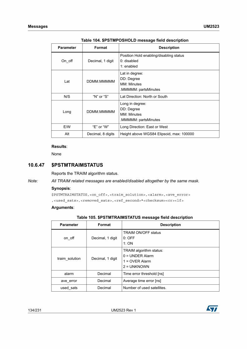
Messages UM2523
134/231 UM2523 Rev 1
Results:
None
10.6.47 $PSTMTRAIMSTATUS
Reports the TRAIM algorithm status.
Note: All TRAIM related messages are enabled/disabled altogether by the same mask.
Synopsis:
$PSTMTRAIMSTATUS,<on_off>,<traim_solution>,<alarm>,<ave_error>
,<used_sats>,<removed_sats>,<ref_second>*<checksum><cr><lf>
Arguments:
Table 104. $PSTMPOSHOLD message field description
Parameter Format Description
On_off Decimal, 1 digit
Position Hold enabling/disabling status
0: disabled
1: enabled
Lat DDMM.MMMMM
Lat in degree:
DD: Degree
MM: Minutes
.MMMMM: partsMinutes
N/S “N” or “S” Lat Direction: North or South
Long DDMM.MMMMM
Long in degree:
DD: Degree
MM: Minutes
.MMMMM: partsMinutes
E/W “E” or “W” Long Direction: East or West
Alt Decimal, 8 digits Height above WGS84 Elipsoid, max: 100000
Table 105. $PSTMTRAIMSTATUS message field description
Parameter Format Description
on_off Decimal, 1 digit
TRAIM ON/OFF status
0: OFF
1: ON
traim_solution Decimal, 1 digit
TRAIM algorithm status:
0 = UNDER Alarm
1 = OVER Alarm
2 = UNKNOWN
alarm Decimal Time error threshold [ns]
ave_error Decimal Average time error [ns]
used_sats Decimal Number of used satellites.

UM2523 Rev 1 135/231
UM2523 Messages
230
Results:
None
10.6.48 $PSTMTRAIMUSED
Reports the satellite used for timing correction.
Note: All TRAIM related messages are enabled/disabled altogether by the same mask.
Synopsis:
$PSTMTRAIMUSED,<on_off>,<used_sats>,<sat1>,...,<satN>*<checksum><cr><lf>
Arguments:
10.6.49 $PSTMTRAIMRES
Reports the time error residuals for satellites used for timing correction.
Note: All TRAIM related messages are enabled/disabled altogether by the same mask.
Synopsis:
$PSTMTRAIMRES,<on_off>,<used_sats>,<res1>,...,<resN>*<checksum><cr><lf>
Arguments:
removed_sats Decimal Number of removed satellites.
ref_second DecimalSecond at which the PPS signal is generated based on reported TRAIM status.
Table 105. $PSTMTRAIMSTATUS message field description (continued)
Parameter Format Description
Table 106. $PSTMTRAIMUSED message field description
Parameter Format Description
on_off Decimal, 1 digit
TRAIM ON/OFF status
0: OFF
1: ON
used_sats Decimal Number of used satellites.
Sat1..satN Decimal Used satellites list.
Table 107. $PSTMTRAIMRES message field description
Parameter Format Description
on_off Decimal, 1 digit
TRAIM ON/OFF status
0: OFF
1: ON
used_sats Decimal Number of used satellites.
res1..resN DecimalTime error residuals for satellites reported in the TRAIMUSED message. Each residual refers to the satellite in the same message position.

Messages UM2523
136/231 UM2523 Rev 1
10.6.50 $PSTMTRAIMREMOVED
Reports the satellite removed by the timing correction algorithm.
Note: All TRAIM related messages are enabled/disabled altogether by the same mask.
Synopsis:
$PSTMTRAIMUSED,<on_off>,<removed_sats>,<sat1>,...,<satN>*<checksum><cr><lf>
Arguments:
10.6.51 $PSTMKFCOV
This message contains the Standard Deviations for position and velocity and their split into north, east and vertical components.
Synopsis:
$PSTMKFCOV,<PosStd>,<PosNcov>,<PosEcov>,<PosVcov>,
<VelStd>,<VelNcov><VelEcov>,<VelVcov>*<checksum><cr><lf>
Arguments:
Example:
$PSTMKFCOV,8.7,50.9,25.4,150.7,0.4,0.1,0.0,0.2*49
Table 108. $PSTMTRAIMREMOVED message field description
Parameter Format Description
on_off Decimal, 1 digit
TRAIM ON/OFF status
0: OFF
1: ON
removed_sats Decimal Number of removed satellites.
Sat1..satN Decimal Removed satellites list.
Table 109. $PSTMKFCOV message field description
Parameter Format Description
PosStd ddd.d Standard Deviation of Position in meters
PosNcov ddd.d Covariance (North/South) in m² (from Kalman Filter)
PosEcov ddd.d Covariance (East/West) in m² (from Kalman Filter)
PosVcov ddd.d Covariance (Vertical) in m² (from Kalman Filter)
VelStd ddd.d Standard Deviation of Velocity in meter/second
VelNcov ddd.d Covariance (North/South) in m²/s (from Kalman Filter)
VelEcov ddd.d Covariance (East/West) in m²/s (from Kalman Filter)
VelVcov ddd.d Covariance (Vertical) in m²/s (from Kalman Filter)

UM2523 Rev 1 137/231
UM2523 Messages
230
10.6.52 $PSTMTIM
Time Validity.
Synopsis:
$PSTMTIM,<Tvalid>,<curr-CPU-Time>*<checksum><cr><lf>
Arguments:
10.6.53 $PSTMDIFF
Time Validity.
Synopsis:
$PSTMDIFF,<ListSize>,<NCS>,
[<Sat1ID>,<Corr1Avl>,]
...
[<SatNID>,<CorrNAvl>,]
*<checksum><cr><lf>
N = number of tracked satellites
Arguments:
10.6.54 $PSTMSBAS
SBAS Satellite Data.
Synopsis:
$PSTMSBAS,<Status>,<SatTrk>,<SatID>,<Elev>,<Azim>,<Sig>*<checksum><cr><lf>
N = number of tracked satellites
Arguments:
Table 110. $PSTMTIM message field description
Parameter Format Description
Tvalid ASCII
“RTC” = time read from RTC
“VALID” = time downloaded from satellite or corrected using position
“INVALID” = time is not valid
curr-CPU-Time DecimalCurrent CPU Time, i.e. the number of ticks since the system started to run
Table 111. $PSTMDIFF message field description
Parameter Format Description
ListSize Decimal, 2 digits Amount of visible satellites in this message (n)
NCS Decimal, 2 digits Number of corrected satellites
SatxID Decimal, 2 digits Satellite x ID (PRN)
CorrxAvl Decimal Correction available for Satellite x

Messages UM2523
138/231 UM2523 Rev 1
Example:
$PSTMSBAS,1,0,124,65,090,00*09
10.6.55 $PSTMSBASM
SBAS Frame.
Synopsis:
$PSTMSBASM,<prn><sbas_frame>*<checksum><cr><lf>
Arguments:
Example:
$PSTMSBASM,123,536A481B40D8063829C12E08704B82DFFDFFEFFF7FFBFFDFFEF06E8037EFB440*6D
10.6.56 $PSTMNOTCHSTATUS
This message provides information on the Adaptive Notch Filter (ANF) status.
Synopsis:
$PSTMNOTCHSTATUS,<kfreq_now_Hz_gps>,<lock_en_gps>,<pwr_gps>,
<ovfs_gps>,<mode_gps>,<kfreq_now_Hz_gln>,<lock_en_gln>,<pwr_gln>, <ovfs_gln>,<mode_gln>*<checksum><cr><lf>
Arguments:
Table 112. $PSTMSBAS message field description
Parameter Format Description
Status Decimal, 1 digit
SBAS Status
0 = no SBAS used
1 = SBAS used
SatTrk Decimal, 1 digit
SBAS Satellite tracked
0 = SBAS Satellite not tracked
1 = SBAS Satellite tracked, decoding is ongoing
2 = SBAS Satellite tracked and decoded. Differential Mode ON
SatID Decimal, 3 digits SBAS Satellite ID
Elev Decimal, 2 digits SBAS Satellite Elevation (in degrees)
Azim Decimal, 3 digits SBAS Satellite Azimuth (in degrees)
Sig Decimal, 2 digits SBAS Satellite Signal Strength CN0 (in dB)
Table 113. $PSTMSBASM message field description
Parameter Format Description
prn Decimal, 3 digits Satellite PRN (Range: from 120 to 140)
sbas_frameHexadecimal, 64
digitsSBAS frame (250 bits + 6 padding)

UM2523 Rev 1 139/231
UM2523 Messages
230
Results:
This message provides the ANF status
When ANF is disabled all parameters are set to zero
Frequency /Power values are meaningful only when Notch is locked
10.6.57 $PSTMLOWPOWERDATA
Reports the status of adaptive low power algorithm.
Synopsis:
$PSTMLOWPOWERDATA,<low power state>,<steady state>,<RESERVED>,
Table 114. $PSTMNOTCHSTATUS message field description
Parameter Format Description
kfreq_now_Hz_gps Decimal, 7 digitsNotch frequency estimation actual value [Hz] (GPS path)
lock_en_gps Decimal, 1 digits Frequency lock flag (GPS path)
pwr_gps Decimal, 5 digitsBand Pass Filter internal power estimation (GPS path)
[dimensionless quantity]
ovfs_gps Decimal, 4 digits
Internal mask output as:
1000 * Notch_Removing_jammer (1/0,TRUE/FALSE)
+ overflow flags status (3 digits).
E.g: “1000” means Block enabled, with no internal overflows detected
mode_gps Decimal, 1 digits
ANF mode operation (GPS path) [0 → ANF disabled;
1 → Always ON(Internal Use only);
2 → Auto insertion mode (suggested);]
kfreq_now_Hz_gln Decimal, 7 digitsNotch frequency estimation actual value [Hz] (GLONASS path)
lock_en_gln Decimal, 1 digits Frequency lock flag (GLONASS path)
pwr_gln Decimal, 24 digitsBand Pass Filter internal power estimation (GLONASS path) [dimensionless quantity]
ovfs_gln Decimal, 4 digits
Internal mask output as:
1000 * Notch_Removing_jammer (1/0,TRUE/FALSE)
+ overflow flags status (3 digits).
E.g: “1000” means Block enabled, with no internal overflows detected
mode_gln Decimal, 1 digits
ANF mode operation (GLONASS path) [0 → ANF disabled;
1 → Always ON (Internal Use only);
2 → Auto insertion mode(suggested);]

Messages UM2523
140/231 UM2523 Rev 1
<RESERVED>,<ehpe>,<RESERVED>,<ehpe_average>,<RESERVED>, <RESERVED>,< eph const mask>,<switch constellation>,<duty cycle enable>,<duty cycle ms off>,<duty cycle state>*<checksum><cr><lf>
Arguments:
Results:
This message provides the adaptive low power status. In the case of dynamic low power disabled, all parameters are set to zero.
10.6.58 $PSTMADCDATA
Reports the ADC channels data read.
Synopsis:
$PSTMADCDATA,<ADC1>,<ADC2>,<ADC3>,<ADC4>,<ADC5>,<ADC6>,<ADC7>,<ADC8>*<checksum><cr><lf>
Arguments:
Table 115. $PSTMLOWPOWERDATA message field description
Parameter Format Description
low power state Decimal, 1 digitsLow power state indicator:
[0 → FULL CONST; 1 → LOW POWER STATE; 2 → EPH REFRESH]
steady state Decimal, 1 digits Steady state reached indicator
RESERVED
RESERVED
ehpe dd.d [m] Estimated Horizontal Position Error [m]
RESERVED
ehpe_average dd.d [m]Estimated Horizontal Position Error Average [m]
RESERVED
RESERVED
eph const mask Decimal, 2 digits Bitfield of completed ephemeris download
switch constellation Decimal, 1 digits Switch constellation features indicator
duty cycle enable Decimal, 1 digits Duty cycle enable indicator
duty cycle ms off Decimal, 3 digits Duty cycle ms signal off
duty cycle state Decimal, 1 digits Duty cycle state indicator
Table 116. $PSTMADCDATA message field description
Parameter Format Description
ADCi DecimalADC data read for the channel i
Values between 0 and 1023

UM2523 Rev 1 141/231
UM2523 Messages
230
Results:
If this message is enabled it provides the ADC channels values read.
Example:
$PSTMADCDATA,754,862,0,754,13,754,754,81*4B
$PSTMADCDATA,793,,,,0,,,59*4D
Note: This message is not supported in the standard NMEA message list. It is automatically enabled when the antenna sensing feature is enabled (see firmware configuration for details on how to enable/disable the feature).
10.6.59 $PSTMANTENNASTATUS
This message reports the status of the antenna (working normally, open or short).
Synopsis:
$PSTMANTENNASTATUS,<status>*<checksum><cr><lf>
Arguments:
Results:
If this message is enabled it provides the antenna status.
Note: This message is not supported in the standard NMEA message list. It is automatically enabled when the antenna sensing feature is enabled (see firmware configuration for details on how to enable/disable the feature).
10.6.60 $PSTMPV
Provides position (Latitude, Longitude, Height), velocity (North, East, Vertical) and root square of covariance matrix values for position and velocity.
Synopsis:
$PSTMPV,<Timestamp>,<Lat>,<N/S>,<Long>,<E/W>,<Alt>,<AltVal>,<Vel_N>,<Vel_E>,<Vel_V>,<P_cov_N>,<P_cov_NE>,<P_cov_NV>,<P_cov_E>,<P_cov_EV>,<P_cov_V>,<V_cov_N>,<V_cov_NE>,<V_cov_NV>,<V_cov_E>,<V_cov_EV>,<V_cov_V>*<checksum><cr><lf>
Arguments:
Table 117. $PSTMANTENNASTATUS message field description
Parameter Format Description
status Decimal
Antenna Status
0 = Antenna NORMAL
1 = Antenna OPEN
2 = Antenna SHORT

Messages UM2523
142/231 UM2523 Rev 1
Example:
$PSTMPV,160635.000,4055.10928,N,01416.56027,E,026.96,M,0.2,0.0,0.1,22.6,12.8,5.8,17.2,10.9,18.8,5.5,4.1,1.7,4.6,0.0,2.7*70
10.6.61 $PSTMPVRAW
Provides not filtered position (Latitude, Longitude, Height), not filtered velocity (North, East, Vertical) and LMS fix related info
Table 118. $PSTMPV message field description
Parameter Format Description
Timestamp hhmmss.sssUTC Time of GPS Sample, example: 160836.000
“.sss” is the fraction of seconds; it assumes non zero values when the fix rate is bigger than 1Hz.
Lat DDMM.MMMMM
Lat in degree:
DD: Degree
MM: Minutes
.MMMMM: partsMinutes
N/S “N” or “S” Lat Direction: North or South
Long DDMM.MMMMM
Long in degree:
DD: Degree
MM: Minutes
.MMMMM: partsMinutes
E/W “E” or “W” Long Direction: East or West
Alt Decimal, 6 digits Height above mean sea level, max: 100000m
Alt-Val “M” Height measure in “M” = meters
Vel_N ddd.d Velocity North component [m/s]
Vel_E ddd.d Velocity East component [m/s]
Vel_V ddd.d Velocity Vertical component [m/s]
P_cov_N ddd.d Position North covariance [m]
P_cov_NE ddd.d Position North-East covariance [m]
P_cov_NV ddd.d Position North-Vertical covariance [m]
P_cov_E ddd.d Position East covariance [m]
P_cov_EV ddd.d Position East-Vertical covariance [m]
P_cov_V ddd.d Position Vertical covariance [m]
V_cov_N ddd.d Velocity North covariance [m/s]
V_cov_NE ddd.d Velocity North-East covariance [m/s]
V_cov_NV ddd.d Velocity North-Vertical covariance [m/s]
V_cov_E ddd.d Velocity East covariance [m/s]
V_cov_EV ddd.d Velocity East-Vertical covariance [m/s]
V_cov_V ddd.d Velocity Vertical covariance [m/s]

UM2523 Rev 1 143/231
UM2523 Messages
230
Synopsis:
$PSTMPVRAW,<Timestamp>,<Lat>,<N/S>,<Long>,<E/W>,<GPSQual>,<Sats>,<HDOP>,<Alt>,<AltVal>,<GeoSep>,<GeoVal>,<Vel_N>,<Vel_E>,<Vel_V>*<checksum><cr><lf>
Arguments:
Example:
$PSTMPVRAW,144056.000,5131.12414,N,00005.31484,W,2,09,1.2,043.31,M,47.0,M,-0.6,0.1,0.6*58
10.6.62 $PSTMPVQ
Provides position and velocity processing noise matrix values.
Synopsis:
$PSTMPVQ,<P_Q_N>,<P_Q_E>,<P_Q_V>,<Q_CLKO>,<Q_GLPD>,<V_Q_N>,<V_Q_E>,<V_Q_V>,<Q_CLKD>,<RESERVED>*<checksum><cr><lf>
Table 119. $PSTMPVRAW message field description
Parameter Format Description
Timestamp hhmmss.sssUTC Time of GPS Sample, example: 160836.000
“.sss” is the fraction of seconds; it assumes non zero values when the fix rate is bigger than 1Hz.
Lat DDMM.MMMMM
Lat in degree:
DD: Degree
MM: Minutes
.MMMMM: partsMinutes
N/S “N” or “S” Lat Direction: North or South
Long DDMM.MMMMM
Long in degree:
DD: Degree
MM: Minutes
.MMMMM: partsMinutes
E/W “E” or “W” Long Direction: East or West
GPSQual Decimal, 1digit
0 = invalid
1 = GPS
2 = DGPS
Sats Decimal, 2 digits Satellites in use: example: 8
HDOP Decimal, 3 digits Horizontal Dilution of Precision, max: 99.0
Alt Decimal, 6 digits Height above mean sea level, max: 100000m
AltVal “M” Reference Unit for Altitude (“M” = meters)
GeoSep Decimal, 4 digits Geoidal Separation measure in “M” = meters
GeoVal “M” Reference Unit for GeoSep (“M” = meters)
Vel_N ddd.d Velocity North component [m/s]
Vel_E ddd.d Velocity East component [m/s]
Vel_V ddd.d Velocity Vertical component [m/s]

Messages UM2523
144/231 UM2523 Rev 1
Arguments:
Example:
$PSTMPVQ,0.0,0.0,0.0,0.0,4.0,3.0,3.0,0.0,3.0,0.0*4A
10.6.63 $PSTMUTC
This message reports the UTC time, date and time offset parameters.
Synopsis:
$PSTMUTC,<utc_time>,<utc_date>,<utc_timestamp>,<utc_offset>,<utc_offset_validity>*<checksum><cr><lf>
Arguments:
Example:
Table 120. $PSTMPVQ message field description
Parameter Format Description
P_Q_N ddd.d Position North processing noise [m]
P_Q_E ddd.d Position East processing noise [m]
P_Q_V ddd.d Position Vertical processing noise [m]
Q_CLKO ddd.d Clock offset processing noise [m]
Q_GLPD ddd.d Glonass path delay [m]
V_Q_N ddd.d Velocity North processing noise [m/s]
V_Q_E ddd.d Velocity East processing noise [m/s]
V_Q_V ddd.d Velocity Vertical processing noise [m/s]
Q_CLKD ddd.d Clock drift processing noise [m/s]
RESERVED - RESERVED for future use
Table 121. $PSTMUTC message field description
Parameter Format Description
utc_time hhmmss.sssUTC Time of Fix, example: 160836.000
“.sss” is the fraction of seconds; it assumes non zero values when the fix rate is bigger than 1Hz.
utc_date ddmmyyyy Date of Fix : ddmmyyyy
utc_timestamp DecimalUTC time expressed as number of seconds since January 6th 1980
utc_offset Decimal, 2 digits UTC to GPS time offset [s]
utc_offset_validity Decimal, 1 digit
UTC to GPS time offset validity
0 = NOT Valid
1 = Read From NVM
2 = Valid (downloaded from sky)

UM2523 Rev 1 145/231
UM2523 Messages
230
$PSTMUTC,161344.000,19062012,1024157624,15,2*52
10.6.64 $PSTMFEDATA
This message reports the current values of all RF front-end registers.
Synopsis:
$PSTMFEDATA,<R0>,<R1>,<R2>,...,<R22>,<R23>,<R24>*<checksum><cr><lf>
Arguments:
Example:
$PSTMFEDATA,ff,ff,3c,6f,9d,78,b7,90,00,00,00,9a,28,f0,3f,30,e0,1a,28,e0,7f,30,40,3a,3a*75
10.6.65 $PSTMERRORMSG
This message reports an error, its location as well as additional (and optional) parameters helpful to understand the error cause.
Synopsis:
$PSTMERRORMSG,<error_code>,<param1>,...,<param6>*<checksum><cr><lf>
Arguments:
Example:
$PSTMERRORMSG,01900001,11111111,11111111,cccccccc,0000dddd,eeeeeeee*26
$PSTMERRORMSG,01920003*2E
10.6.66 $PSTMGNSSINTEGRITY
This message is sent from GNSS Teseo to the host periodically it is enabled in the message list.
Table 122. $PSTMFEDATA message field description
Parameter Format Description
From R0 up to R22Hexadecimal, 2
digitsRESERVED
R23Hexadecimal, 2
digitsAutomatic gain control register for GPS+GALILEO RF path
R24Hexadecimal, 2
digitsAutomatic gain control register for GLONASS or BEIDOU RF path
Table 123. $PSTMERRORMSG message field description
Parameter Format Description
error_codeHexadecimal, 8
digitsIndicates where the error comes from.
Param1 up to param6Hexadecimal, 8
digitsOptional parameters used to understand the error. There can be 0 additional parameter.

Messages UM2523
146/231 UM2523 Rev 1
This message is implemented and supported only in Binary Image 4.5.8 and later.
Synopsis:
$PSTMGNSSINTEGRITY,<type>,<pos_const_mask>,<pos_err_AtoB>,<pos_err_AtoC>,<pos_err_BtoC>,<time_const_mask>,<time_err_AtoB>,<time_err_AtoC>,<time_err_BtoC>*<checksum><cr><lf>
Arguments:
10.6.67 $PSTMNAVM
Navigation Data Frame.
Synopsis:
$PSTMNAVM,<msg_id>,<prn>,<nav_frame>*<checksum><cr><lf>
Arguments:
Details:
Table 124. $PSTMGNSSINTEGRITY message field description
Parameter Format Description
type Decimal Integrity message type (currently always 0)
pos_const_mask Decimal Position related constellation mask
pos_err_AtoB DoublePosition error of second active constellation in comparison to the first one as meters
pos_err_AtoC DoublePosition error of third active constellation in comparison to the first one as meters
pos_err_BtoC DoublePosition error of third active constellation in comparison to the second one as meters
time_const_mask Decimal Time related constellation mask
time_err_AtoB DoubleTime error of second active constellation in comparison to the first one as nanoseconds
time_err_AtoC DoubleTime error of third active constellation in comparison to the first one as nanoseconds
time_err_BtoC DoubleTime error of third active constellation in comparison to the second one as nanoseconds
Table 125. $PSTMNAVM message field description
Parameter Format Description
msg_id Decimal, 1 digitsMessage ID (GPS = 0, GLONASS = 1, GALILEO = 3, BEIDOU = 7)
prn Decimal, 3 digits Satellite PRN (Range: depending on the constellation)
nav_frameHexadecimal, up to
80 digitsNavigation data frame (length: depending on the constellation)

UM2523 Rev 1 147/231
UM2523 Messages
230
The navigation frame parameter depends on the constellation. The following table describes its meaning (see each constellation ICD document for details):
Note: In the above table, “word” means a 32-bit little endian encoded word, while “msb” means most significant bit(s).It means that, in a little endian architecture system, the navigation frame (converted to binary format) can be directly copied into a C 32 bit unsigned integer words array. In other words:
For GPS, the navigation frame can be copied into a C language variable defined according to the following type definition:
typedef tU32 gps_subframe_t [10];
For GLONASS, the navigation frame can be copied into a C language variable defined according to the following type definition:
typedef tU08 glo_subframe_t [22];
Note: For strings for #1 to #5 just the first 11 bytes will be used, while for strings from #6 to #15 all 22 bytes will be used by storing two consecutive strings (e.g. strings #7 and #6). In this latter case the first sting (e.g. string #n) will be stored in the second part of the array (i.e. from byte #12 to #22), and the second string (e.g. string #n+1) will be stored in the first part of the array (i.e. from byte #1 to #11).
For GALILEO, the navigation frame can be copied in a C language variable defined according to the following type definition:
typedef tU32 gal_subframe_t [4];
Note: The GALILEO navigation frame contains the message payload, encoded according to the following table.
Table 126. Navigation frame data types
Constellation Type Length (bits) Length (bytes)
Note
GPS Sub-frame 300 40 (10 words)For each 32 bit word 30 bits are used (the 2 msb are ignored)
GLONASS 1 or 2 strings
85 or
170
(85+85)
11 or
22 (11+11 bytes)
One string for each message for strings from 1 to 5.
Two strings for each message for strings from 6 to 15.
For the first byte of each string the 3 msb are ignored and the 4th is always zero. The payload is 84 bits long
GALILEO payload 128 16 (4 words)Each message contains the payload from I/NAV message (see Note for details)
BEIDOU Sub-frame 300 40 (10 words)For each 32 bit word 30 bits are used (the 2 msb are ignored)

Messages UM2523
148/231 UM2523 Rev 1
For BEIDOU, the navigation frame can be copied in a C language variable defined according to the following type definition:
typedef tU32 bds_subframe_t [10];
where tU32 is a 32-bit unsigned integer type and tU08 is a 8-bit unsigned integer type.
Example:
$PSTMNAVM,0,4,00AFC32268A9BD26337FF43AC40B60D1B8B80018C8EE0B0330BDA238AF711D185E1000C088790781*23
10.6.68 $PSTMEPHEM
Ephemeris Data Dump.
This message is sent as a reply to a $PSTMDUMPEPHEMS command.
Synopsis:
$PSTMEPHEM,<sat_id>,<N>,<byte1>,...,<byteN>*<checksum><cr><lf>
Arguments:
The N Bytes that are in the message are the dump of a structure that contains all the information of the ephemeris.
Data formats are constellation dependant.
Figure 14. Galileo payload, 128[bit], 32-bit packing
31 30 29 28 27 26 25 24 23 22 21 20 19 18 17 16 15 14 13 12 11 10 9 8 7 6 5 4 3 2 1 0
0 Data k 0-31 (112 bit)
1 Data k 32-63 (112 bit)
2 Data k 64-95 (112 bit)
3 Data k 96-111 (112 bit) Data j (16 bit)
Table 127. $PSTMEPHEM message field description
Parameter Format Description
sat_id Decimal, 2 digits Satellite number
N Decimal, 1 Digit Number of the ephemeris data bytes
byte1 Hexadecimal, 2 digits First byte of the ephemeris data
byteN Hexadecimal, 2 digits Last byte of the ephemeris data
Table 128. $PSTMEPHEM message field description for GPS constellation
Bits Structure Member Description
16 week Week number of the Issue of Data
16 toe Time of week for ephemeris epoch
16 toc Time of week for clock epoch
8 iode1 Issue of data 1

UM2523 Rev 1 149/231
UM2523 Messages
230
8 iode2 Issue of data 2
10 iodc Issue of data clock
14 i_dot Rate of inclination angle.
8 RESERVED
24 omega_dot Rate of right ascension.
8 RESERVED Must be 0.
16 crs Amplitude of the sine harmonic correction to the orbit radius.
16 crc Amplitude of the cosine harmonic correction to the orbit radius.
16 cusAmplitude of the sine harmonic correction to the argument of latitude.
16 cucAmplitude of the cosine harmonic correction to the argument of latitude.
16 cisAmplitude of the sine harmonic correction to the angle of inclination.
16 cicAmplitude of the cosine harmonic correction to the angle of inclination.
16 motion_difference Mean motion difference from computed value
16 RESERVED Must be 0.
32 inclination Inclination angle at reference time
32 e Eccentricity.
32 root_A Square root of major axis.
32 mean_anomaly Mean anomaly at reference time.
32 omega_zero Longitude of ascending node of orbit plane at weekly epoch.
32 perigee Argument of perigee.
8 time_group_delay Estimated group delay differential.
8 af2 Second order clock correction.
16 af1 First order clock correction.
22 af0 Constant clock correction.
1 RESERVED RESERVED for use by GNSS library – must be 1
1 RESERVED RESERVED for use by GNSS library – must be 1
1 RESERVED RESERVED for use by GNSS library – must be 1
1 available Contains 1 if ephemeris is available, 0 if not
1 health Contains 1 if the satellite is unhealthy, 0 if healthy
1 RESERVED Must be 0.
4 accuracy Accuracy
Table 128. $PSTMEPHEM message field description for GPS constellation (continued)
Bits Structure Member Description

Messages UM2523
150/231 UM2523 Rev 1
Table 129. $PSTMEPHEM message field description for GLONASS constellation
Bits Structure Member Description
16 week Week number of the Issue of Data.
16 toe Time of week for ephemeris epoch.
4 toe_lsb Time of week for ephemeris epoch (LBS).
11 NACalendar day number within the four-year period since the beginning of last leap year (almanac).
7 tb Time of ephemeris index.
2 M Type of satellite 00=GLONASS 01=GLONASS-M .
2 P1 Time interval between two adjacent tb parameters.
1 P3Number of satellites for which almanac is transmitted within this frame 0=4 1=5.
1 P2 Flag of oddness ("1") or evenness ("0") of the value of tb
1 P4 Flag to show that ephemeris parameters are present.
2 KP Notification on forthcoming leap second correction of UTC
1 RESERVED
27 xn Satellite PZ-90 x coordinate at epoch tb.
5 xn_dot_dot Satellite PZ-90 x velocity at epoch tb.
24 xn_dot Satellite PZ-90 x acceleration component at epoch tb.
5 n Slot number (1…24).
3 Bn Healthy flags.
27 yn Satellite PZ-90 y coordinate at epoch tb.
5 yn_dot_dot Satellite PZ-90 y acceleration component at epoch tb.
24 yn_dot Satellite PZ-90 y velocity at epoch tb.
8 age_h Age of predicted ephemeris (hours)
27 zn Satellite PZ-90 z coordinate at epoch tb.
5 zn_dot_dot Satellite PZ-90 z acceleration component at epoch tb.
24 zn_dot Satellite PZ-90 z velocity at epoch tb.
8 RESERVED Must be 0.
11 gamma_n Satellite clock frequency drift at epoch tb.
5 E_n Age of the ephemeris information.
4 freq_id Frequency ID
12 RESERVED
22 tau_n Satellite clock correction at epoch tb.
10 RESERVED Must be 0.
32 tau_c GLONASS to UTC(SU) time correction.
22 tau_GPS GLONASS to GPS system time correction.
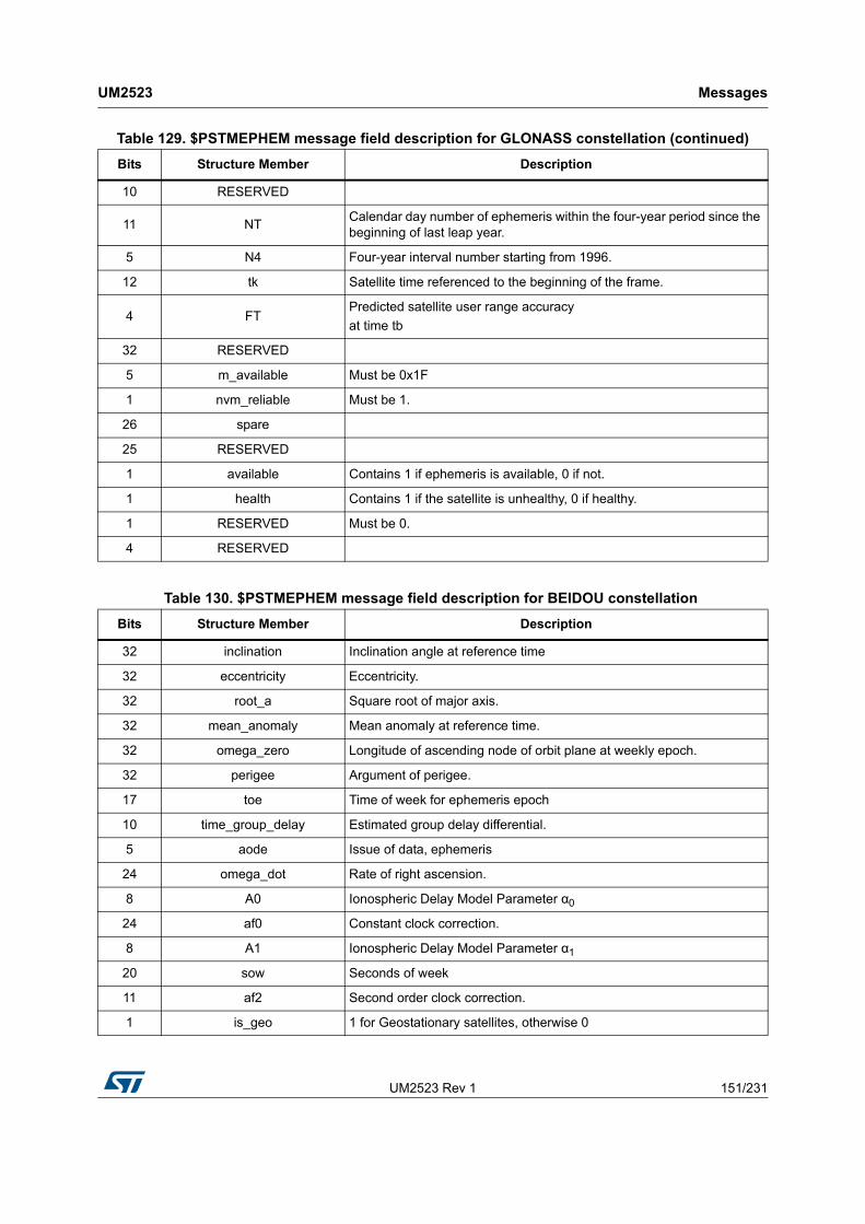
UM2523 Rev 1 151/231
UM2523 Messages
230
10 RESERVED
11 NTCalendar day number of ephemeris within the four-year period since the beginning of last leap year.
5 N4 Four-year interval number starting from 1996.
12 tk Satellite time referenced to the beginning of the frame.
4 FTPredicted satellite user range accuracy
at time tb
32 RESERVED
5 m_available Must be 0x1F
1 nvm_reliable Must be 1.
26 spare
25 RESERVED
1 available Contains 1 if ephemeris is available, 0 if not.
1 health Contains 1 if the satellite is unhealthy, 0 if healthy.
1 RESERVED Must be 0.
4 RESERVED
Table 129. $PSTMEPHEM message field description for GLONASS constellation (continued)
Bits Structure Member Description
Table 130. $PSTMEPHEM message field description for BEIDOU constellation
Bits Structure Member Description
32 inclination Inclination angle at reference time
32 eccentricity Eccentricity.
32 root_a Square root of major axis.
32 mean_anomaly Mean anomaly at reference time.
32 omega_zero Longitude of ascending node of orbit plane at weekly epoch.
32 perigee Argument of perigee.
17 toe Time of week for ephemeris epoch
10 time_group_delay Estimated group delay differential.
5 aode Issue of data, ephemeris
24 omega_dot Rate of right ascension.
8 A0 Ionospheric Delay Model Parameter α0
24 af0 Constant clock correction.
8 A1 Ionospheric Delay Model Parameter α1
20 sow Seconds of week
11 af2 Second order clock correction.
1 is_geo 1 for Geostationary satellites, otherwise 0
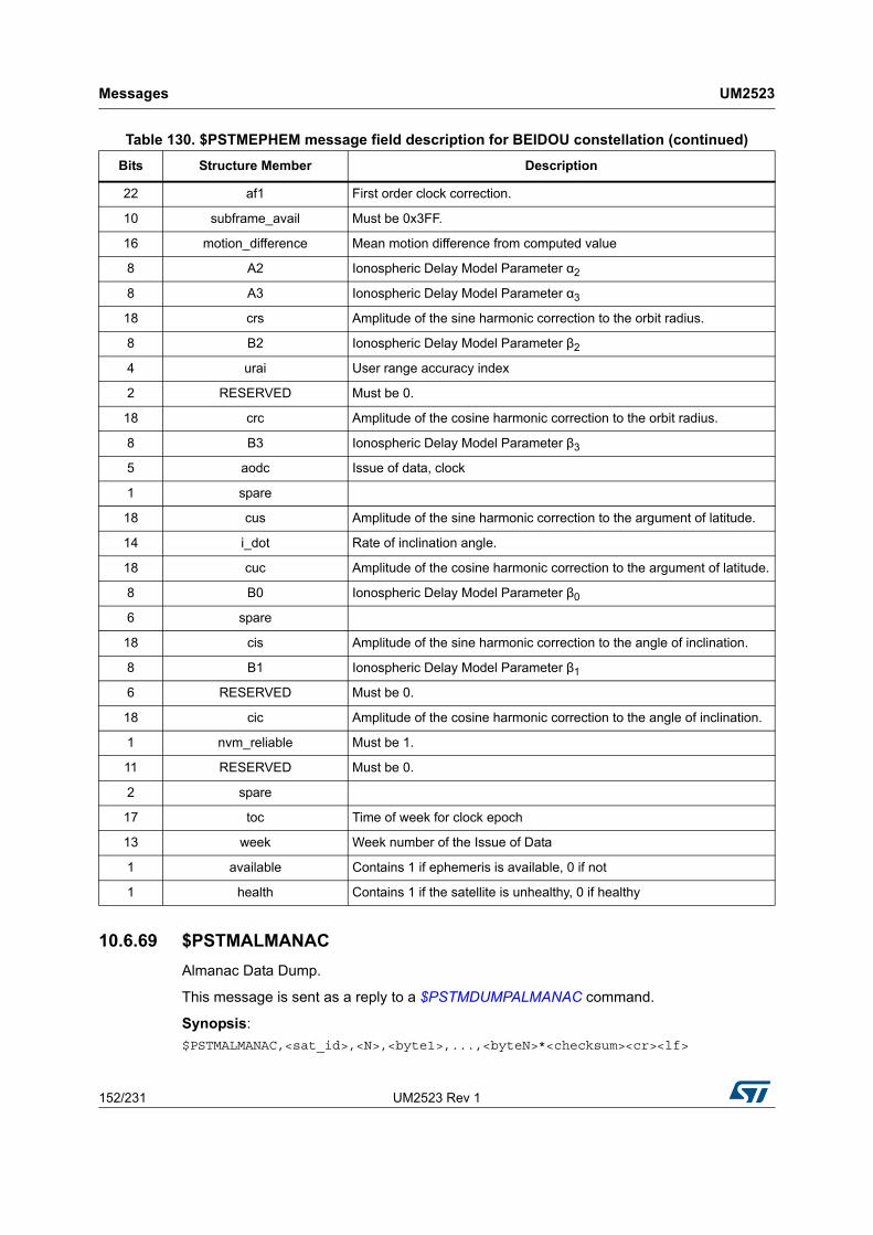
Messages UM2523
152/231 UM2523 Rev 1
10.6.69 $PSTMALMANAC
Almanac Data Dump.
This message is sent as a reply to a $PSTMDUMPALMANAC command.
Synopsis:
$PSTMALMANAC,<sat_id>,<N>,<byte1>,...,<byteN>*<checksum><cr><lf>
22 af1 First order clock correction.
10 subframe_avail Must be 0x3FF.
16 motion_difference Mean motion difference from computed value
8 A2 Ionospheric Delay Model Parameter α2
8 A3 Ionospheric Delay Model Parameter α3
18 crs Amplitude of the sine harmonic correction to the orbit radius.
8 B2 Ionospheric Delay Model Parameter β2
4 urai User range accuracy index
2 RESERVED Must be 0.
18 crc Amplitude of the cosine harmonic correction to the orbit radius.
8 B3 Ionospheric Delay Model Parameter β3
5 aodc Issue of data, clock
1 spare
18 cus Amplitude of the sine harmonic correction to the argument of latitude.
14 i_dot Rate of inclination angle.
18 cuc Amplitude of the cosine harmonic correction to the argument of latitude.
8 B0 Ionospheric Delay Model Parameter β0
6 spare
18 cis Amplitude of the sine harmonic correction to the angle of inclination.
8 B1 Ionospheric Delay Model Parameter β1
6 RESERVED Must be 0.
18 cic Amplitude of the cosine harmonic correction to the angle of inclination.
1 nvm_reliable Must be 1.
11 RESERVED Must be 0.
2 spare
17 toc Time of week for clock epoch
13 week Week number of the Issue of Data
1 available Contains 1 if ephemeris is available, 0 if not
1 health Contains 1 if the satellite is unhealthy, 0 if healthy
Table 130. $PSTMEPHEM message field description for BEIDOU constellation (continued)
Bits Structure Member Description

UM2523 Rev 1 153/231
UM2523 Messages
230
Arguments:
The N Bytes that are in the message are the dump of a structure that contains all the information of the almanac.
Data formats is constellation dependent
Table 131. $PSTMALMANAC message field description
Parameter Format Description
sat_id Decimal, 2 digits Satellite number
N Decimal, 1 digit Number of the almanac data bytes
byte1 Hexadecimal, 2 digits First byte of the almanac data
byteN Hexadecimal, 2 digits Last byte of the almanac data
Table 132. $PSTMALMANAC message field description for GPS constellation
Bits Structure Member Description
8 satid The satellite number
16 week The week number for the epoch
8 toa Reference time almanac.
16 e Eccentricity.
16 delta_i Rate of inclination angle.
16 omega_dot Rate of right ascension.
24 root_A Square root of semi-major axis.
24 omega_zero Longitude of ascending node of orbit plane at weekly epoch.
24 perigee Argument of perigee.
24 mean_anomaly Mean anomaly at reference time.
11 af0 Constant clock correction.
11 af1 First order clock correction.
1 health Contains 1 if the satellite is unhealthy 0 if healthy.
1 available Contains 1 if almanac is available 0 if not.
Table 133. $PSTMALMANAC field description for GLONASS constellation
Bits Structure Member Description
8 satid The satellite number.
16 week The week number for the epoch.
8 toa Reference time almanac.
5 n_A Slot number (1…24).
5 H_n_A Carrier frequency channel number.

Messages UM2523
154/231 UM2523 Rev 1
10.6.70 $PSTMGPSSUSPENDED
Message sent in response to command $PSTMGPSSUSPEND
Synopsis:
$PSTMGPSSUSPENDED*<checksum><cr><lf>
Arguments:
None.
Results:
Message sent in case of error.
10.6.71 PSTMUSEDSATS
This message reports the number of used satellites for each constellation.
NMEA message list bitmask (64 bits): 0000 0040 0000 0000
Synopsis:
$PSTMUSEDSATS,<GPS_n>,<GLONASS_n>,<GALILEO_n>,<BEIDOU_n>,<QZSS_n>*<checksum><cr><lf>
Arguments:
2 M_n_A Type of satellite 00=GLONASS 01=GLONASS-M.
10 tau_n_A Satellite clock correction.
15 epsilon_n_A Eccentricity.
21 t_lambda_n_A Time of the first ascending node passage.
21 lambda_n_A Longitude of ascending node of orbit plane at almanac epoch.
18 delta_i_n_A Inclination angle correction to nominal value.
7 delta_T_n_dot_A Draconian period rate of change.
22 delta_T_n_A Draconian period correction.
16 omega_n_A Argument of perigee.
1 health Contains 1 if the satellite is unhealthy 0 if healthy.
1 available Contains 1 if almanac is available 0 if not.
32 Tau_c
11 NA
5 N4
16 Spare
Table 133. $PSTMALMANAC field description for GLONASS constellation (continued)
Bits Structure Member Description

UM2523 Rev 1 155/231
UM2523 Messages
230
Results:
None.
Example:
$PSTMUSEDSATS,08,07,00,00,00*2B
10.7 ST system configuration messages
10.7.1 $PSTMSETPAROK
Message sent in response to command $PSTMSETPAR
Synopsis:
$PSTMSETPAROK ,<ConfigBlock><ID>*<checksum><cr><lf>
Arguments:
Results:
Message sent in case of successful operation.
10.7.2 $PSTMSETPARERROR
Message sent in response to command $PSTMSETPAR
Table 134. $PSTMUSEDSATS message field description
Parameter Format Description
GPS_n Decimal, 2 digitsNumber of used satellites of the GPS constellation
GLONASS_n Decimal, 2 digitsNumber of used satellites of the GLONASS constellation
GALILEO_n Decimal, 2 digitsNumber of used satellites of the GALILEO constellation
BEIDOU_n Decimal, 2 digitsNumber of used satellites of the BEIDOU constellation
QZSS_n Decimal, 2 digitsNumber of used satellites of the QZSS constellation
Table 135. $PSTMSETPAROK message field description
Parameter Format Description
ConfigBlock Decima1,1 digit
Indicates one of the configuration blocks:
1=Current Configuration,
2 = Default Configuration,
3 = NVM Stored configuration.
ID Decimal, 3 digitsID - Identifier
(see Configuration Data Block as described in FW Configuration document)

Messages UM2523
156/231 UM2523 Rev 1
Synopsis:
$PSTMSETPARERROR*<checksum><cr><lf>
Argument:
No argument
Results:
Message sent in case of error.
10.7.3 $PSTMRESTOREPAROK
Message sent in response to command $PSTMRESTOREPAR
Synopsis:
$PSTMRESTOREPAROK*<checksum><cr><lf>
Arguments:
None.
Results:
Message sent in case of successful operation.
10.7.4 $PSTMRESTOREPARERROR
Message sent in response to command $PSTMRESTOREPAR
Synopsis:
$PSTMRESTOREPARERROR*<checksum><cr><lf>
Arguments:
None.
Results:
Message sent in case of error.
10.7.5 $PSTMSAVEPAROK
Message sent in response to command $PSTMSAVEPAR
Synopsis:
$PSTMSAVEPAROK*<checksum><cr><lf>
Arguments:
None.
Results:
Message sent in case of successful operation.
10.7.6 $PSTMSAVEPARERROR
Message sent in response to command $PSTMSAVEPAR
Synopsis:
$PSTMSAVEPARERROR*<checksum><cr><lf>
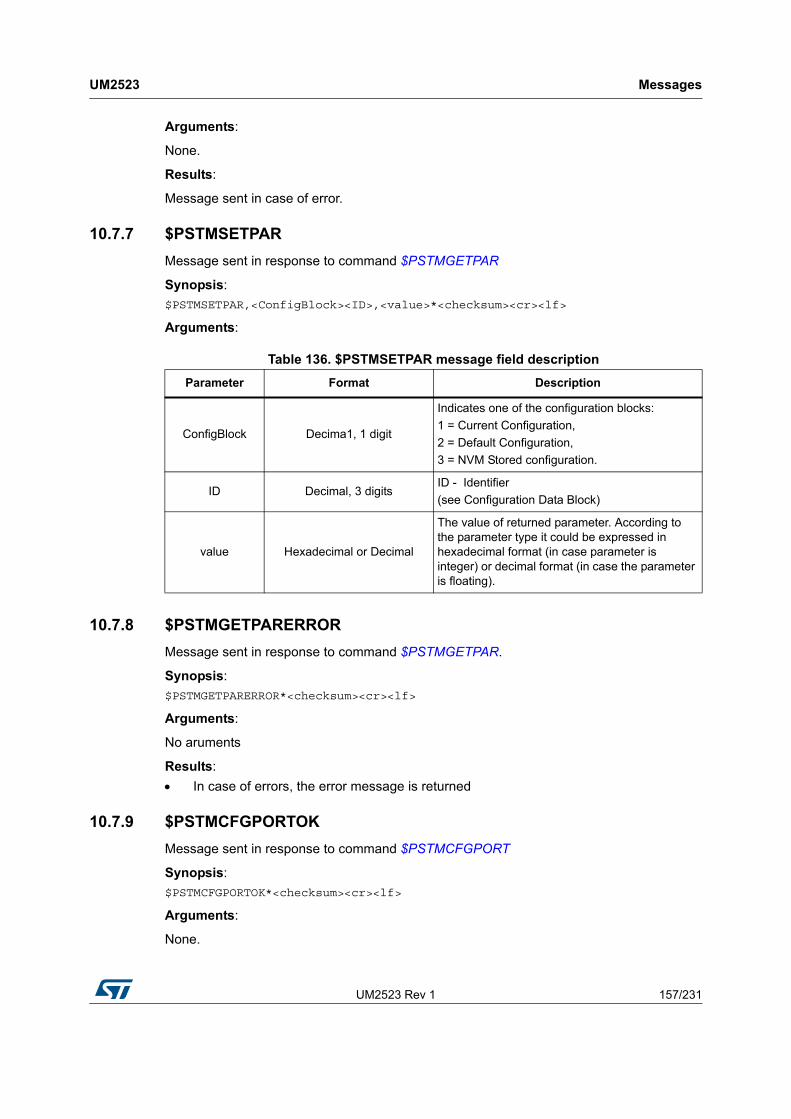
UM2523 Rev 1 157/231
UM2523 Messages
230
Arguments:
None.
Results:
Message sent in case of error.
10.7.7 $PSTMSETPAR
Message sent in response to command $PSTMGETPAR
Synopsis:
$PSTMSETPAR,<ConfigBlock><ID>,<value>*<checksum><cr><lf>
Arguments:
10.7.8 $PSTMGETPARERROR
Message sent in response to command $PSTMGETPAR.
Synopsis:
$PSTMGETPARERROR*<checksum><cr><lf>
Arguments:
No aruments
Results:
In case of errors, the error message is returned
10.7.9 $PSTMCFGPORTOK
Message sent in response to command $PSTMCFGPORT
Synopsis:
$PSTMCFGPORTOK*<checksum><cr><lf>
Arguments:
None.
Table 136. $PSTMSETPAR message field description
Parameter Format Description
ConfigBlock Decima1, 1 digit
Indicates one of the configuration blocks:
1 = Current Configuration,
2 = Default Configuration,
3 = NVM Stored configuration.
ID Decimal, 3 digitsID - Identifier
(see Configuration Data Block)
value Hexadecimal or Decimal
The value of returned parameter. According to the parameter type it could be expressed in hexadecimal format (in case parameter is integer) or decimal format (in case the parameter is floating).

Messages UM2523
158/231 UM2523 Rev 1
Results:
Message sent in case of successful operation.
10.7.10 $PSTMCFGPORTERROR
Message sent in response to command $PSTMCFGPORT
Synopsis:
$PSTMCFGPORTERROR*<checksum><cr><lf>
Arguments:
None.
Results:
Message sent in case of error.
10.7.11 $PSTMCFGANTSENSOK
Message sent in response to command $PSTMCFGANTSENS
Synopsis:
$PSTMCFGANTSENSOK*<checksum><cr><lf>
Arguments:
None.
Results:
Message sent in case of successful operation.
10.7.12 $PSTMCFGANTSENSERROR
Message sent in response to command $PSTMCFGANTSENS
Synopsis:
$PSTMCFGANTSENSERROR*<checksum><cr><lf>
Arguments:
None.
Results:
Message sent in case of error.
10.7.13 $PSTMCFGCLKSOK
Message sent in response to command $PSTMCFGCLKS
Synopsis:
$PSTMCFGCLKSOK*<checksum><cr><lf>
Arguments:
None.
Results:

UM2523 Rev 1 159/231
UM2523 Messages
230
Message sent in case of successful operation.
10.7.14 $PSTMCFGCLKSERROR
Message sent in response to command $PSTMCFGCLKS
Synopsis:
$PSTMCFCLKSERROR*<checksum><cr><lf>
Arguments:
None.
Results:
Message sent in case of error.
10.7.15 $PSTMCFGMSGLOK
Message sent in response to command $PSTMCFGMSGL
Synopsis:
$PSTMCFGMSGLOK*<checksum><cr><lf>
Arguments:
None.
Results:
Message sent in case of successful operation.
10.7.16 $PSTMCFGMSGLERROR
Message sent in response to command $PSTMCFGMSGL
Synopsis:
$PSTMCFGMSGLERROR*<checksum><cr><lf>
Arguments:
None.
Results:
Message sent in case of error.
10.7.17 $PSTMCFGGNSSOK
Message sent in response to command $PSTMCFGGNSS
Synopsis:
$PSTMCFGGNSSOKOK*<checksum><cr><lf>
Arguments:
None.
Results:
Message sent in case of successful operation.

Messages UM2523
160/231 UM2523 Rev 1
10.7.18 $PSTMCFGGNSSERROR
Message sent in response to command $PSTMCFGGNSS
Synopsis:
$PSTMCFGGNSSERROR*<checksum><cr><lf>
Arguments:
None.
Results:
Message sent in case of error.
10.7.19 $PSTMCFGSBASOK
Message sent in response to command $PSTMCFGSBAS
Synopsis:
$PSTMCFGSBASOK*<checksum><cr><lf>
Arguments:
None.
Results:
Message sent in case of successful operation.
10.7.20 $PSTMCFGSBASERROR
Message sent in response to command $PSTMCFGSBAS
Synopsis:
$PSTMCFGSBASERROR*<checksum><cr><lf>
Arguments:
None.
Results:
Message sent in case of error.
10.7.21 $PSTMCFGLPAOK
Message sent in response to command $PSTMCFGLPA
Synopsis:
$PSTMCFGLPAOK*<checksum><cr><lf>
Arguments:
None.
Results:
Message sent in case of successful operation.

UM2523 Rev 1 161/231
UM2523 Messages
230
10.7.22 $PSTMCFGLPAERROR
Message sent in response to command $PSTMCFGLPA
Synopsis:
$PSTMCFGLPAERROR*<checksum><cr><lf>
Arguments:
None.
Results:
Message sent in case of error.
10.7.23 $PSTMCFGLPSOK
Message sent in response to command $PSTMCFGLPS
Synopsis:
$PSTMCFGLPSOK*<checksum><cr><lf>
Arguments:
None.
Results:
Message sent in case of successful operation.
10.7.24 $PSTMCFGLPSERROR
Message sent in response to command $PSTMCFGLPS
Synopsis:
$PSTMCFGLPSERROR*<checksum><cr><lf>
Arguments:
None.
Results:
Message sent in case of error.
10.7.25 $PSTMCFGAJMOK
Message sent in response to command $PSTMCFGAJM
Synopsis:
$PSTMCFGAJMOK*<checksum><cr><lf>
Arguments:
None.
Results:
Message sent in case of successful operation.

Messages UM2523
162/231 UM2523 Rev 1
10.7.26 $PSTMCFGAJMERROR
Message sent in response to command $PSTMCFGAJM
Synopsis:
$PSTMCFGAJMERROR*<checksum><cr><lf>
Arguments:
None.
Results:
Message sent in case of error.
10.7.27 $PSTMCFGODOOK
Message sent in response to command $PSTMCFGODO
Synopsis:
$PSTMCFGODOOK*<checksum><cr><lf>
Arguments:
None.
Results:
Message sent in case of successful operation.
10.7.28 $PSTMCFGODOERROR
Message sent in response to command $PSTMCFGODO
Synopsis:
$PSTMCFGODOERROR*<checksum><cr><lf>
Arguments:
None.
Results:
Message sent in case of error.
10.7.29 $PSTMCFGGEOFENCEOK
Message sent in response to command $PSTMCFGGEOFENCE
Synopsis:
$PSTMCFGGEOFENCEOK*<checksum><cr><lf>
Arguments:
None.
Results:
Message sent in case of successful operation.

UM2523 Rev 1 163/231
UM2523 Messages
230
10.7.30 $PSTMCFGGEOFENCEERROR
Message sent in response to command $PSTMCFGGEOFENCE
Synopsis:
$PSTMCFGGEOFENCEERROR*<checksum><cr><lf>
Arguments:
None.
Results:
Message sent in case of error.
10.7.31 $PSTMCFGGEOCIROK
Message sent in response to command $PSTMCFGGEOCIR
Synopsis:
$PSTMCFGGEOCIROK*<checksum><cr><lf>
Arguments:
None.
Results:
Message sent in case of successful operation.
10.7.32 $PSTMCFGGEOCIRERROR
Message sent in response to command $PSTMCFGGEOCIR
Synopsis:
$PSTMCFGGEOCIRERROR*<checksum><cr><lf>
Arguments:
None.
Results:
Message sent in case of error.
10.7.33 $PSTMCFGGNSSOK
Message sent in response to command $PSTMCFGGNSS
Synopsis:
$PSTMCFGGNSSOKOK*<checksum><cr><lf>
Arguments:
None.
Results:
Message sent in case of successful operation.

Messages UM2523
164/231 UM2523 Rev 1
10.7.34 $PSTMCFGGNSSERROR
Message sent in response to command $PSTMCFGGNSS
Synopsis:
$PSTMCFGGNSSERROR*<checksum><cr><lf>
Arguments:
None.
Results:
Message sent in case of error.
10.7.35 $PSTMCFGCONSTOK
Message sent in response to command $PSTMCFGCONST
Synopsis:
$PSTMCFGCONSTOK*<checksum><cr><lf>
Arguments:
None.
Results:
Message sent in case of successful operation.
10.7.36 $PSTMCFGCONSTERROR
Message sent in response to command $PSTMCFGCONST
Synopsis:
$PSTMCFGCONSTERROR*<checksum><cr><lf>
Arguments:
None.
Results:
Message sent in case of error.
10.7.37 $PSTMCFGTHGNSSOK
Message sent in response to command $PSTMCFGTHGNSS
Synopsis:
$PSTMCFGTHGNSSOK*<checksum><cr><lf>
Arguments:
None.
Results:
Message sent in case of successful operation.

UM2523 Rev 1 165/231
UM2523 Messages
230
10.7.38 $PSTMCFGTHGNSSERROR
Message sent in response to command $PSTMCFGTHGNSS
Synopsis:
$PSTMCFGTDATAOK*<checksum><cr><lf>
Arguments:
None.
Results:
Message sent in case of error.
10.7.39 $PSTMCFGTDATAOK
Message sent in response to command $PSTMCFGTDATA
Synopsis:
$PSTMCFGTDATAOK*<checksum><cr><lf>
Arguments:
None.
Results:
"Message sent in case of successful operation.
10.7.40 $PSTMCFGTDATAERROR
Message sent in response to command $PSTMCFGTDATA
Synopsis:
$PSTMCFGTDATAERROR*<checksum><cr><lf>
Arguments:
None.
Results:
Message sent in case of error.
10.8 Geofencing NMEA messages
10.8.1 $PSTMGEOFENCECFGOK
Message sent in response to command $PSTMGEOFENCECFG
Synopsis:
$PSTMGEOFENCECFGOK*<checksum><cr><lf>
Arguments:
No argument
Results:
Message sent in case of successful operation.

Messages UM2523
166/231 UM2523 Rev 1
10.8.2 $PSTMGEOFENCECFGERROR
Message sent in response to command $PSTMGEOFENCECFG
Synopsis:
$PSTMGEOFENCECFGERROR*<checksum><cr><lf>
Arguments:
No argument
Results:
Message sent in case of error.
10.8.3 $PSTMGEOFENCESTATUS
This message is sent from GNSS Teseo to the host as response to $PSTMGEOFENCEREQ.
Geofence reports a bitmap against which circle is raising the alarm.
This message is implemented and supported only in Binary Image 4.5.8 and later.
Synopsis:
$PSTMGEOFENCESTATUS,<timestamp>,<datestamp>,<status_1>,<status_2>,…,<status_x>*<checksum><cr><lf>
Arguments:
10.8.4 $PSTMGEOFENCEREQERROR
Message sent in response to command $PSTMGEOFENCEREQ
Synopsis:
$PSTMGEOFENCEREQERROR*<checksum><cr><lf>
Arguments:
No argument
Results:
Table 137. $PSTMGEOFENCESTATUS message field description
Parameter Format Description
timestamp Decimal, 6 digits
Hour (2 digit)
Minute (2 digit)
Seconds (2 digit)
datestamp Decimal, 8 digits
Year (4 digit);
Month (2 digit);
Day (2 digit)
status_x Decimal, 1 digit
Geo fencing status for each circle where:
0 = Status unknown
1 = Current position is outside the circle
2 = Current position on circle boundary
3 = Current position is inside the circle

UM2523 Rev 1 167/231
UM2523 Messages
230
Message sent in case of error.
10.9 Odometer NMEA messages
10.9.1 $PSTMODOSTARTOK
Message sent in response to command $PSTMODOSTART
Synopsis:
$PSTMSTARTOK*<checksum><cr><lf>
Arguments:
No argument
Results:
Message sent in case of successful operation.
10.9.2 $PSTMODOSTARTERROR
Message sent in response to command $PSTMODOSTART
Synopsis:
$PSTMSTARTERROR*<checksum><cr><lf>
Arguments:
No argument
Results:
Message sent in case of error.
10.9.3 $PSTMODOSTOPOK
Message sent in response to command $PSTMODOSTOP
Synopsis:
$PSTMSTOPOK*<checksum><cr><lf>
Arguments:
No argument
Results:
Message sent in case of successful operation.
10.9.4 $PSTMODOSTOPERROR
Message sent in response to command $PSTMODOSTOP.
Synopsis:
$PSTMSTOPERROR*<checksum><cr><lf>
Arguments:
No argument

Messages UM2523
168/231 UM2523 Rev 1
Results:
Message sent in case of error.
10.9.5 $PSTMODORESETOK
Message sent in response to command $PSTMODORESET.
Synopsis:
$PSTMRESETOK*<checksum><cr><lf>
Arguments:
No argument
Results:
Message sent in case of successful operation.
10.9.6 $PSTMODORESETERROR
Message sent in response to command $PSTMODORESET.
Synopsis:
$PSTMRESETERROR*<checksum><cr><lf>
Arguments:
No argument
Results:
Message sent in case of error.
10.9.7 $PSTMODO
This message is sent from GNSS Teseo III to the host periodically if Odometer subsystem is enabled and related messages are in the message list.
This message is implemented and supported only in Binary Image 4.5.8 and later.
Synopsis:
$PSTMODO,<timestamp>,<date-stamp>,<odo-A>,<odo-B>,<odo-pon>*<checksum><cr><lf>
Arguments:
Table 138. $PSTMODO message field description
Parameter Format Description
timestamp Decimal, 6 digits
Hour (2 digit)
Minute (2 digit)
Seconds (2 digit)
date-stamp Decimal, 8 digits
Year (4 digit);
Month (2 digit);
Day (2 digit)
odo-A Unsigned Odometer A value
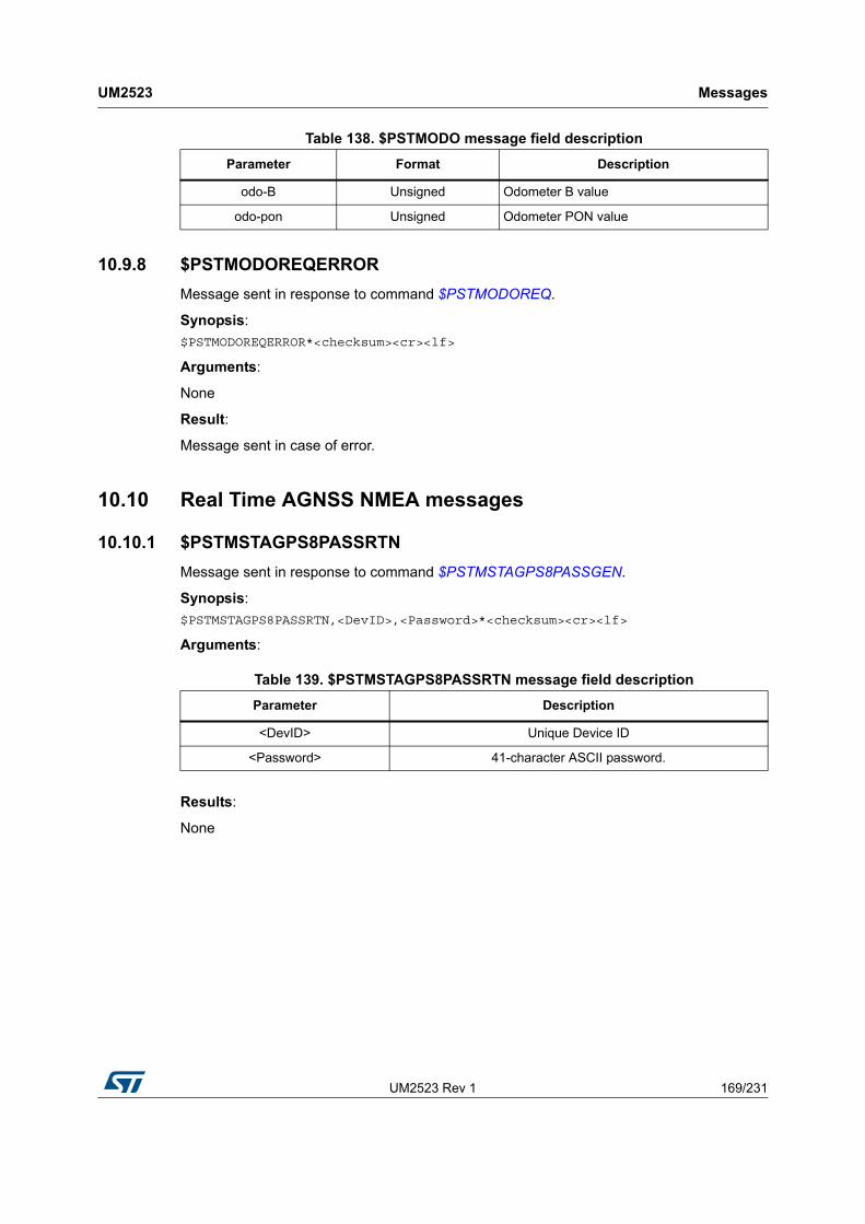
UM2523 Rev 1 169/231
UM2523 Messages
230
10.9.8 $PSTMODOREQERROR
Message sent in response to command $PSTMODOREQ.
Synopsis:
$PSTMODOREQERROR*<checksum><cr><lf>
Arguments:
None
Result:
Message sent in case of error.
10.10 Real Time AGNSS NMEA messages
10.10.1 $PSTMSTAGPS8PASSRTN
Message sent in response to command $PSTMSTAGPS8PASSGEN.
Synopsis:
$PSTMSTAGPS8PASSRTN,<DevID>,<Password>*<checksum><cr><lf>
Arguments:
Results:
None
odo-B Unsigned Odometer B value
odo-pon Unsigned Odometer PON value
Table 138. $PSTMODO message field description
Parameter Format Description
Table 139. $PSTMSTAGPS8PASSRTN message field description
Parameter Description
<DevID> Unique Device ID
<Password> 41-character ASCII password.

Firmware Configuration Data Block (CDB) UM2523
170/231 UM2523 Rev 1
11 Firmware Configuration Data Block (CDB)
All configuration parameters are grouped in a data block. Each field is addressed by a unique ID. The IDs are made by three digits: the most significant one represents the parameter type and the others are used to identify different parameters of the same type.
The table below includes all parameters which can be changed to apply a different configuration to the firmware.
The IDs not reported in the table should be considered as RESERVED and must be left untouched to avoid unexpected system behaviors.
Table 140. Configuration data block list
IDParameter
nameSize
bytesAllowed values
Default Description
100 Reserved 1 0...2 0
101NMEA Port Number
1 0...2 2 Set NMEA port number
102NMEA Port Baudrate
1
0x0 = 300 baud
0x1 = 600 baud
0x2 = 1200 baud
0x3 = 2400 baud
0x4 = 4800 baud
0x5 = 9600 baud
0x6 = 14400 baud
0x7 = 19200 baud
0x8 = 38400 baud
0x9 = 57600 baud
0xA = 115200 baud
0xB = 230400 baud
0xC = 460800 baud
0xD = 921600 baud
0xA Set NMEA Baudrate
103 Reserved 1 0
104GNSS Mask Angle
1 0 …. 45 5Set the GNSS Mask Angle for low Satellite Elevation
105
GNSS Tracking Threshold [dB]
1 9...40 10 Set the satellites tracking threshold
106 Reserved 1 0xA
120Cold Start Type
1
0xF = clear Almanach, Ephem, Time &Position
0xE = clear Ephemeris, Time, Position
0xESet the cold start type with selective data erase

UM2523 Rev 1 171/231
UM2523 Firmware Configuration Data Block (CDB)
230
121
NMEA Decimal Digits for Speed and Course values
1First nibble: 0x1...0x8
Second nibble: 0x1...0x80x11
Allow setting the number of decimal digits for the speed and course data in the NMEA messages.
124
NMEA and Debug Output Redirection
1
0x11 = NMEA
0x44 = NMEA
0x81 = NMEA over I2C
0x11Configure the output method for NMEA messages (over UART or SD card)
125Notch Filter Setting
1 0x0...0xF 0x0Enable or disable the Notch Filter usage
126 Reserved 1 0...1 1
127NMEA Decimal Digits
1First nibble: 0x1...0x8
Second nibble: 0x1...0x80x55
Allow setting the number of decimal digits for the position data in the NMEA messages.
128Differential Source Type
1 0...3 0x3Allow selecting the differential mode source type.
129GLONASS Satellite ID Type
1 0...1 0x1
Allow setting the GLONASS satellite ID type used in the GSV and GSA messages.0x0 – the satellite ID is based on frequency
0x1 – the satellite ID is based on slot number.
130CPU clock speed
1 0x00, 0x10, 0x20, 0x30, 0x02 0x30Allow setting the CPU clock source and speed.
131NMEA Talker ID
1 ‘P’, ‘L’, ‘N’ ‘P’Allow setting the second character of the NMEA talker ID.
132
GNSS positioning CN0 Threshold [dB]
1 9...40 15Set the satellites CN0 threshold for the positioning stage
134Configuration Version ID
1 0...255 0Allow setting a version number for the specific configuration
135SBAS Default Service
1 0...15 15 Set the SBAS default Service
138RTCM Port Number
1 0...2 0Set the serial port number for the RTCM input.
Table 140. Configuration data block list (continued)
IDParameter
nameSize
bytesAllowed values
Default Description

Firmware Configuration Data Block (CDB) UM2523
172/231 UM2523 Rev 1
139RTCM Port Baud rate
1
0x0 = 300 baud
0x1 = 600 baud
0x2 = 1200 baud
0x3 = 2400 baud
0x4 = 4800 baud
0x5 = 9600 baud
0x6 = 14400 baud
0x7 = 19200 baud
0x8 = 38400 baud
0x9 = 57600 baud
0xA = 115200 baud
0xB = 230400 baud
0xC = 460800 baud
0xD = 921600 baud
0xASet the baudrate for the RTCM input serial port.
From 140
To 188
Even IDs
RF front-end address register and operation
1
b0...b5 = address (from 0 to 24)
b6...b7= operation (00b or 01b or 10b)
0xFF = Don’t Touch
Set the address and the operation to be performed on the corresponding RF front end register. The address is reported in the first 6 bits. The operation is reported in the last 2 bits. Any address from 0 to 24 is allowed.
Supported operations are:
b6...b7 = 00b: overwrite register with provided value
b6...b7 = 01b: Perform OR operation between register and provided value
b6...b7 = 11b: Perform AND operation between register and provided value.
Provided value is the value reported in the next parameter (e.g. 140 reports the address and operation for the value reported on 141)
Note: Using 0xFF for this parameter means don’t touch the front-end register. If the front-end registers configuration is not needed, all parameters from 140 to 188 (even IDs) should be set to 0xFF. This is the default value of standard ST image.
Table 140. Configuration data block list (continued)
IDParameter
nameSize
bytesAllowed values
Default Description

UM2523 Rev 1 173/231
UM2523 Firmware Configuration Data Block (CDB)
230
From 141
To 189
Odd IDs
RF front-end data register value
1Any RF front-end supported values (see front-end reference manual)
0xFF
The value to be applied to the front-end register pointed by the previous address and operation parameter (e.g. 141 reports the value to be applied to the address reported on 140)
190
NMEA Msg-List 0 output rate scaling factor.
1 1...255 1
Message list output rate scaling factor referred to the fix rate.
Examples:
1 = message list is sent out at the selected fix-rate
2 = message list is sent out every 2 fixes
N = message list is sent out every N fixes
191
NMEA Msg-List 1 output rate scaling factor.
1 1...255 1
Message list output rate scaling factor referred to the fix rate.
Examples:
1 = message list is sent out at the selected fix-rate
2 = message list is sent out every 2 fixes
N = message list is sent out every N fixes
192
NMEA Msg-List 2 output rate scaling factor.
1 1...255 1
Message list output rate scaling factor referred to the fix rate.
Examples:
1 = message list is sent out at the selected fix-rate
2 = message list is sent out every 2 fixes
N = message list is sent out every N fixes
193 Reserved 1 0
194 Reserved 1 0
195 Reserved 1 1
197 PPS Clock 1 16,32,48,64 32Allow setting the PPS clock. For accurate timing application, 64 is mandatory.
198GNSS Mask Angle Positioning
1 0 …. 45 1
Set the GNSS Mask Angle for positioning algorithm. Satellites with elevation below the mask angle are not used in the position solution.
Table 140. Configuration data block list (continued)
IDParameter
nameSize
bytesAllowed values
Default Description

Firmware Configuration Data Block (CDB) UM2523
174/231 UM2523 Rev 1
199Local geodetic datum
1 0...215 255
Set the local geodetic datum to be used in position reporting over the NMEA messages. Not valid number (e.g. 255) means default datum which is WSG84.
Table 140. Configuration data block list (continued)
IDParameter
nameSize
bytesAllowed values
Default Description

UM2523 Rev 1 175/231
UM2523 Firmware Configuration Data Block (CDB)
230
200Application ON/OFF
4
0x2 = GPS_2D_FIX_ENABLE
0x4 = SBAS_ENABLE
0x8 = SBAS_SAT_ON_GSV_MSG_ENABLE
0x10 = Reserved
0x20 = 2.5_PPM_TCXO_ENABLE
0x40 = NMEA_v301_ENABLE
0x80 = QZSS_DISTRIBUTED_ACQ_MODE_ENABLE
0x200 = CONFIG_TXT_HEADER_EN.
0x400 = ST_HEADERS_ENABLE
0x800 = RTCM_ENABLE
0x1000 = FDE_ENABLE
0x4000 = WALKING_MODE_ENABLE
0x8000 = STOP_DETECTION_ENABLE
0x10000 = GPS_ENABLE
0x20000 = GLONASS_ENABLE
0x40000 = QZSS_ENABLE
0x80000 = NMEA_GNGSV_ENABLE
0x100000 = NMEA_GNGSA_ENABLE
0x200000 = GLONASS_USE_ENABLE
0x400000 = GPS_USE_ENABLE
0x800000 = QZSS_USE_ENABLE
0x1000000 = Reserved
0x2000000 = Reserved
0x4000000 = Reserved
0x8000000 = Reserved
0x10000000 = RESERVED
0x20000000 = HIGH_DYNAMICS_ON_OFF
0x40000000 = NMEA_RAW_ON_OFF
0x80000000 = LOW_POWER_ON_OFF
0x09419644
Activates/Deactivates GNSS application features
201NMEA Port Msg-List 0 (LOW)
4 0x0000.0000 to 0xFFFF.FFFF0x28843
5FSet NMEA Message List 0 (32 bits low)
Table 140. Configuration data block list (continued)
IDParameter
nameSize
bytesAllowed values
Default Description

Firmware Configuration Data Block (CDB) UM2523
176/231 UM2523 Rev 1
202NCO Range max.
4 -132000 to 132000 0x0Set NCO range max. value
in Hz
203NCO Range min.
4 -132000 to 132000 0x0Set NCO range min. value
in Hz
204 NCO Center 4 -132000 to 132000 0x0Set NCO center frequency
Offset in Hz
205Position Data Time Delay [ms]
4 0..(fix rate time period) 80 ms
Set the time delay between the measurements (on UTC second) and the position data delivery.
NOTE: To reduce the jittering of the NMEA message list 2 data delivery, the messages are sent over the uart port after a fixed delay from the measurement time. This delay can be configured to achieve the best jitter reduction at different CPU speed setting.
206GPIO Port0 CFG0
4 0x0000.0000 to 0xFFFF.FFFF0xFFFFFFFF
Config0 for GPIO Port0
207GPIO Port0 CFG1
4 0x0000.0000 to 0xFFFF.FFFF0x00000
000Config1 for GPIO Port0
208GPIO Port1 CFG0
4 0x0000.0000 to 0xFFFF.FFFF0xFFFFFFFF
Config0 for GPIO Port1
209GPIO Port1 CFG1
4 0x0000.0000 to 0xFFFF.FFFF0x00000
000Config1 for GPIO Port1
210NMEA Port Msg-List 1 (LOW)
4 0x0000.0000 to 0xFFFF.FFFF 0x0Set NMEA Message List 1 (32 bits low)
211NMEA Port Msg-List 2 (LOW)
4 0x0000.0000 to 0xFFFF.FFFF 0x0Set NMEA Message List 2 (32 bits low)
213 Reserved 4 -0x00000
00
214 Reserved 4 -0x00000
00
215 Reserved 4 0x0000.0000 to 0xFFFF.FFFF 0x0
218SBAS satellite parameters
4 -0xFFFFFFFF
Allow setting parameters (PRN, longitude and service) for new SBAS satellites not supported by the was library. Not valid value (e.g. 0xFFFFFFFF) means not used.
Table 140. Configuration data block list (continued)
IDParameter
nameSize
bytesAllowed values
Default Description

UM2523 Rev 1 177/231
UM2523 Firmware Configuration Data Block (CDB)
230
219SBAS satellite parameters
4 -0xFFFFFFFF
Allow setting parameters (PRN, longitude and service) for new SBAS satellites not supported by the was library. Not valid value (e.g. 0xFFFFFFFF) means not used
220
Adaptive Low Power operating mode setting 1
4 -15 m,10s, 10s, 180s
Allow setting the operative mode for low power algorithm.
221
Adaptive Low Power operating mode setting 2
4 -4,60s,9,
31minAllow setting the operative mode for low power algorithm.
222
LMS operating mode setting 1
4 -1,0,0,,50
m,
50m,
Allow setting parameters for the LMS algorithm
223
LMS operating mode setting 2
4 -5,3,-223m
Allow setting parameters for the LMS algorithm
224
Adaptive Low Power operating mode setting 3
41,1,740
msAllow setting the operative mode for low power algorithm.
225
ADC channel read configuration parameters
4 - 0x3FEAllow setting parameters for configuration of ADC channels reading
226
Antenna Sensing configuration parameters
4 -0x7D096
010
Allow setting parameters for configuration of Antenna Sensing feature
Table 140. Configuration data block list (continued)
IDParameter
nameSize
bytesAllowed values
Default Description

Firmware Configuration Data Block (CDB) UM2523
178/231 UM2523 Rev 1
227Application ON/OFF 2
4
0x1 = NMEA_COMMAND_ECO_ENABLE
0x2 = NMEA_TTFF_MESSAGE_ENABLE
0x4 = FEW_SATS_POS_ESTIMATION_ENABLE
0x8 = Reserved
0x20 = NMEA_IN_OUT_INTERFACE_SELECT
0x40 = Reserved
0x80 = Reserved
0x100 = COMPASS_ENABLE
0x200 = COMPASS_USAGE_ENABLE
0x800 = RTC_USAGE_DISABLING
0x1000 = FAST_SATELLITE_DROP_ENABLE
0x2000 = RESERVED
0x4000 = EXCLUDED_SATS_REPORTING_ENABLE
0x345Activates/Deactivates GNSS application features
228NMEA Port Msg-List 0 (HIGH)
4 0x0000.0000 to 0xFFFF.FFFF 0x2000Set NMEA Message List 0 (32 bits high)
229NMEA Port Msg-List 1 (HIGH)
4 0x0000.0000 to 0xFFFF.FFFF 0x0Set NMEA Message List 1 (32 bits high)
230NMEA Port Msg-List 2 (HIGH)
4 0x0000.0000 to 0xFFFF.FFFF 0x0Set NMEA Message List 2 (32 bits high)
231 Reserved 4 0x0000.0000 to 0xFFFF.FFFF 0x0
232 Reserved 4 0x0000.0000 to 0xFFFF.FFFF 0x0
233 Reserved 4 0x0000.0000 to 0xFFFF.FFFF 0x0
234 Reserved 4 0x0000.0000 to 0xFFFF.FFFF 0x0
235 Reserved 4 0x0000.0000 to 0xFFFF.FFFF 0x0
236 Reserved 4 0x0000.0000 to 0xFFFF.FFFF 0x0
Table 140. Configuration data block list (continued)
IDParameter
nameSize
bytesAllowed values
Default Description

UM2523 Rev 1 179/231
UM2523 Firmware Configuration Data Block (CDB)
230
237
Default GPS MIN-MAX week number
4MIN: 0x0000 to 0xFFFF - MAX: 0x0000 to 0xFFFF
MIN = 1821
MAX = 3300
Set default MIN-MAX range for GPS week number.
NOTE: Min week number is used for correct GPS week number decoding. Max week number is used for GPS week validity check.
238Default UTC delta time
4 0x0000.0000 to 0xFFFF.FFFF 16Default value of GPS time to UTC delta time in seconds (leap second)
240 Reserved 4 0x0000.0000 to 0xFFFF.FFFF 0x1FF
241 Reserved 4 0x0000.0000 to 0xFFFF.FFFF 0x0
245 Reserved 4 0x0, 0xA, 0xB 0x0
249 Reserved 4 - 0x1
250 Reserved 4 -0x80000
00
253GPIO Port0 Mode AFSLA
4 0x0000.0000 to 0xFFFF.FFFF0xFFF7C3F0
AFSLA register configuration for GPIO Port0
254GPIO Port0 Mode AFSLB
4 0x0000.0000 to 0xFFFF.FFFF0x00000
000AFSLB register configuration for GPIO Port0
255GPIO Port1 Mode AFSLA
4 0x0000.0000 to 0xFFFF.FFFF0xFFFFFFFF
AFSLA register configuration for GPIO Port1
256GPIO Port1 Mode AFSLB
4 0x0000.0000 to 0xFFFF.FFFF0x00000
000AFSLB register configuration for GPIO Port1
257Low Power Setting
4 0x0, 0x1 0x1Allow configuration of low power functionalities
260WLS configuration params
4 -0x00190
A00WLS algorithm configuration params
261
Dynamic modes configurations
4 0,1,3 0Allow setting the dynamic mode for the satellite tracking engine.
263Nmea over serial configuration
4 0xE80Allow configuring parameters for nmea over serial feature
264 Reserved 4 0x0000.0000 to 0xFFFF.FFFF0x10180
000
265 Reserved 4 0x0000.0000 to 0xFFFF.FFFF 0x80000
266 Reserved 4 0x0000.0000 to 0xFFFF.FFFF 0x80000
267 Reserved 4 0x0000.0000 to 0xFFFF.FFFF0x00000
10E
Table 140. Configuration data block list (continued)
IDParameter
nameSize
bytesAllowed values
Default Description

Firmware Configuration Data Block (CDB) UM2523
180/231 UM2523 Rev 1
268Geofencing Configuration 0
4 0x0000.0000 to 0xFFFF.FFFF 0x0 Geofencing configuration field 0
270Odometer Configuration
4 0x0000.0000 to 0xFFFF.FFFF0x03E80
000Odometer configuration field
272GNSS Integrity
4 0x0..0x3 0x0Enabling/disabling position and time integrity feature
303GNSS Fix Rate
8 > 0.1 seconds 1.0
Set the GNSS fix rate period in seconds.
NOTE: high fix rates may require a different setting (e.g. 208MHz) of the CPU speed.
304 Reserved 8 From -90.0 to 90.040.9174
7
305 Reserved 8 From -180.0 to 180.014.2758
6
306 Reserved 8 From -1500 to 10000088.4330
7
307GPS RF delay correction
8 718E-9Time delay compensation for the GPS RF path.
308GLONASS RF delay correction
8 -420E-9Time delay compensation for the GLONASS RF path.
309TRAIM alarm threshold
8 15nsTime error threshold for the satellites exclusion in the TRAIM algorithm.
310COMPASS RF delay correction
8 100E-9Time delay compensation for the COMPASS RF path.
311 Reserved 8 718E-9
314Geofencing Circle 0 Latitude
841.1147
3
Allows to set up the geofencing circle number 0 by choosing its latitude as a double precision floating number
315Geofencing Circle 0 Longitude
813.8809
3
Allows to set up the geofencing circle number 0 by choosing its longitude as a double precision floating number
316Geofencing Circle 0 Radius
8 10.0
Allows to set up the geofencing circle number 0 by choosing its radius in meters as a double precision floating number
Table 140. Configuration data block list (continued)
IDParameter
nameSize
bytesAllowed values
Default Description

UM2523 Rev 1 181/231
UM2523 Firmware Configuration Data Block (CDB)
230
11.1 CDB-ID 101 – NMEA port setting
Allow setting the NMEA port number.
System reboot needed to have new setting in use.
317Geofencing Circle 1 Latitude
841.1214
8
Allows to set up the geofencing circle number 1 by choosing its latitude as a double precision floating number
318Geofencing Circle 1 Longitude
813.8714
6
Allows to set up the geofencing circle number 1 by choosing its longitude as a double precision floating number
319Geofencing Circle 1 Radius
8 10.0
Allows to set up the geofencing circle number 1 by choosing its radius in meters as a double precision floating number
320Geofencing Circle 2 Latitude
841.2434
1
Allows to set up the geofencing circle number 2 by choosing its latitude as a double precision floating number
321Geofencing Circle 2 Longitude
813.7744
3
Allows to set up the geofencing circle number 2 by choosing its longitude as a double precision floating number
322Geofencing Circle 2 Radius
8 10.0
Allows to set up the geofencing circle number 2 by choosing its radius in meters as a double precision floating number
323Geofencing Circle 3 Latitude
841.2432
8
Allows to set up the geofencing circle number 3 by choosing its latitude as a double precision floating number
324Geofencing Circle 3 Longitude
813.7742
4
Allows to set up the geofencing circle number 3 by choosing its longitude as a double precision floating number
325Geofencing Circle 3 Radius
8 10.0
Allows to set up the geofencing circle number 3 by choosing its radius in meters as a double precision floating number
Table 140. Configuration data block list (continued)
IDParameter
nameSize
bytesAllowed values
Default Description

Firmware Configuration Data Block (CDB) UM2523
182/231 UM2523 Rev 1
11.2 CDB-ID 102 – NMEA port baudrate setting
Allow setting the baudrate for the NMEA port number. The translation table is in Table 141: CDB-ID 102 field description.
System reboot needed to have new setting in use.
11.3 CDB-ID 104 – Mask angle setting
Allow setting the minimum elevation angle at which a satellite can be tracked. Satellite with elevation below the mask angle cannot be tracked.
System reboot needed to have new setting in use.
11.4 CDB-ID 105 – GNSS tracking threshold
Allow setting the minimum CN0 [dB] at which a satellite can be tracked. Satellite with CN0 below the configured threshold cannot be tracked.
A GNSS engine reset (suspend/restart) is needed to have this setting in place.
11.5 CDB-ID 120 – Cold start setting
Allow setting the data to be cleared during the COLD start command execution. This parameter is a bitmask where bit=1 indicates the data to be cleared.
Table 141. CDB-ID 102 field description
Parameter Value Baudrate
0x0 300 baud
0x1 600 baud
0x2 1200 baud
0x3 2400 baud
0x4 4800 baud
0x5 9600 baud
0x 6 14400 baud
0x 7 19200 baud
0x 8 38400 baud
0x 9 57600 baud
0xA 115200 baud
0xB 230400 baud
0xC 460800 baud
0xD 921600 baud

UM2523 Rev 1 183/231
UM2523 Firmware Configuration Data Block (CDB)
230
Any bitmask combination is allowed, the default one is 0xE.
This setting is in place as soon as the $PSTMSETPAR is performed.
11.6 CDB-ID 121 – Number of decimal digits for speed and course data in NMEA messages
Allow setting the number of decimal digits for the speed and course data in NMEA messages. It affects both RMC and VTG messages
It is possible to set a different number of decimal digits.
11.7 CDB-ID 122 – NMEA format configuration
Allow setting the change the format of NMEA. Note that this changes the default value of this parameter the Bit 6 of CDB-ID 200 – Application ON/OFF is bypassed.
The default value of this parameter is 0x0C.
In case of wrong configuration NMEA is configured as 3.01 like.
Table 142. CDB-ID 120 field description
Bit Bitmask Description
0 0x1 Clear almanacs
1 0x2 Clear ephemeris
2 0x4 Clear position
3 0x8 Clear time
Table 143. CDB-ID 121 field description
Bit Values Description
From B0 to B3 From 1 up to 5 Allow setting the number of decimal digits for speed value in RMC and VTG massages
From B4 to B7 From 1 up to 5Allow setting the number of decimal digits for course value in RMC and VTG messages.
Table 144. CDB-ID 122 field description
Bit Values Description
From B0 to B3 Hexadecimal
Changes the NMEA format
0x01 = NMEA is 3.00 like
0x02 = NMEA is 3.01 like
0x04 = NMEA is 4.10 like
0x0C = Depends on Bit 6 of CDB-ID 200

Firmware Configuration Data Block (CDB) UM2523
184/231 UM2523 Rev 1
11.8 CDB-ID 124 – NMEA output redirection
Allow setting the output channel for NMEA messages. Supported channels are UART and SD card. UART is the default channel. If the SD card is selected for NMEA output but the SD card is not present in the slot, the system switches automatically to the UART mode.
This parameter is made by two bit masks (4 bits each one):
11.9 CDB-ID 125 – Notch filter setting
Allow setting the Notch filter usage on GPS RF path, GLONASS RF path or both GPS and GLONASS RF paths. The notch filter can be enabled and inserted in the RF path (normal mode – see b0, b1 below) or the notch filter can be enabled but inserted only if locked on a jammer (auto-insertion mode – see b2, b3 below).
11.10 CDB-ID 127 – Number of decimal digits in NMEA position messages
Allow setting the number of decimal digits for the NMEA position messages.
It is possible to set a different number of decimal digits for GGA and for both RMC and GLL messages.
Table 145. CDB-ID 124 field description
Bit Bitmask Description
From B0 to B3 Reserved
From B4 to B7
0x10=enable/disable UART output
0x40=enable/disable SD output
0x80=enable/disable I2C output
Bit mask for NMEA output configuration (only one bit can be enabled at the same time in the bitmask)
Table 146. CDB-ID 125 field description
Bitmask Description
b0...b3 = 0x00 Notch Filter is disabled on both GPS and GLONASS paths
b0 Enable/disable notch filter on GPS path (normal mode).
b1 Enable/disable notch filter on GLONASS path (normal mode).
b2 Enable/disable notch filter on GPS path in auto-insertion mode.
b3 Enable/disable notch filter on GLONASS path in auto-insertion mode.
Table 147. CDB-ID 127 field description
Bit Values Description
From B0 to B3 From 1 up to 5 Allow setting the number of decimal digits for the RMC and GLL massages
From B4 to B7 From 1 up to 5Allow setting the number of decimal digits for the GGA massage.
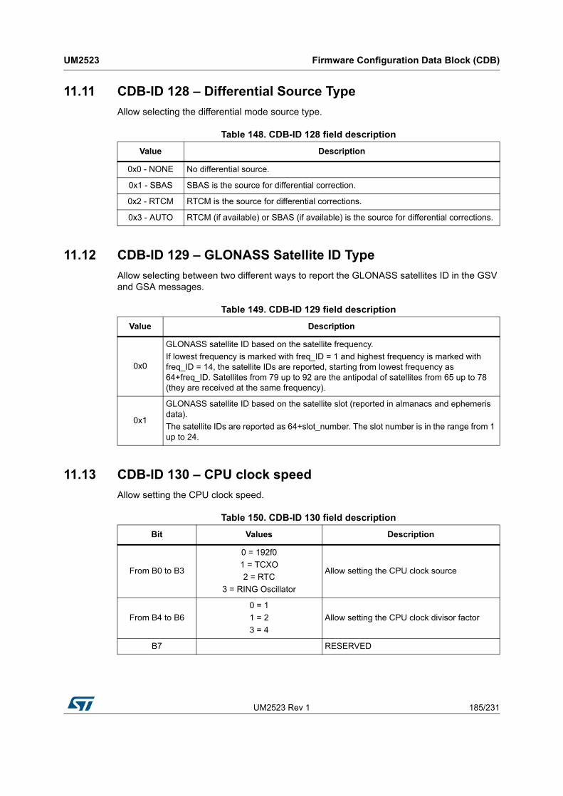
UM2523 Rev 1 185/231
UM2523 Firmware Configuration Data Block (CDB)
230
11.11 CDB-ID 128 – Differential Source Type
Allow selecting the differential mode source type.
11.12 CDB-ID 129 – GLONASS Satellite ID Type
Allow selecting between two different ways to report the GLONASS satellites ID in the GSV and GSA messages.
11.13 CDB-ID 130 – CPU clock speed
Allow setting the CPU clock speed.
Table 148. CDB-ID 128 field description
Value Description
0x0 - NONE No differential source.
0x1 - SBAS SBAS is the source for differential correction.
0x2 - RTCM RTCM is the source for differential corrections.
0x3 - AUTO RTCM (if available) or SBAS (if available) is the source for differential corrections.
Table 149. CDB-ID 129 field description
Value Description
0x0
GLONASS satellite ID based on the satellite frequency.
If lowest frequency is marked with freq_ID = 1 and highest frequency is marked with freq_ID = 14, the satellite IDs are reported, starting from lowest frequency as 64+freq_ID. Satellites from 79 up to 92 are the antipodal of satellites from 65 up to 78 (they are received at the same frequency).
0x1
GLONASS satellite ID based on the satellite slot (reported in almanacs and ephemeris data).
The satellite IDs are reported as 64+slot_number. The slot number is in the range from 1 up to 24.
Table 150. CDB-ID 130 field description
Bit Values Description
From B0 to B3
0 = 192f0
1 = TCXO
2 = RTC
3 = RING Oscillator
Allow setting the CPU clock source
From B4 to B6
0 = 1
1 = 2
3 = 4
Allow setting the CPU clock divisor factor
B7 RESERVED

Firmware Configuration Data Block (CDB) UM2523
186/231 UM2523 Rev 1
Examples:
0x00 sets the CPU speed at 192f0 MHz
0x10 sets the CPU speed at 96f0 MHz
0x20 sets the CPU speed at 64f0 MHz
0x30 sets the CPU speed at 48f0 MHz
11.14 CDB-ID 131 – NMEA Talker ID
Allow setting the second character of the NMEA talker ID for the GGA, RMC, VTG, GLL NMEA sentences. The talked ID for GSV and GSA is managed in a different way (see CDB-ID 200, bits 19 and 20).
11.15 CDB-ID 132 – GNSS Positioning CN0 threshold
Allow setting the minimum CN0 [dB] at which a satellite can be used in the position solution. Satellites with CN0 below the configured threshold are not used in the position evaluation.
A GNSS engine reset (suspend/restart) is needed to have this setting in place.
11.16 CDB-ID 134 – Configuration version ID
Allow setting a version identification number for the configuration data block. This parameter has two main purposes:
Mark a specific configuration data block with a unique identifier which is readable at the application level using the command interface
Replace any saved configuration data with the default setting configuration if the version number of the default setting is different from the version number of the saved data block. Example: the GNSS module is flashed with a firmware which has an embedded default setting marked as version 1. The user changes some parameters and saves the new configuration. The module is then updated with a firmware which has the configuration version marked as version 2. At the first startup the saved configuration (version 1) is automatically cleared and the version 2 configuration is applied to the GNSS software.
11.17 CDB-ID 135 – SBAS default service
Allow setting the default service for the SBAS library.
System reboot needed to have new setting in use.
Note: For compatibility, a default SBAS PRN can also be set. In that case the SBAS AUTO service will be used.
11.18 CDB-ID 138 – RTCM port setting
Allow setting the RTCM port number.

UM2523 Rev 1 187/231
UM2523 Firmware Configuration Data Block (CDB)
230
Note: The RTCM feature is supported on all serial ports. It can be configured also to work on the same serial port already used for NMEA messages.
System reboot needed to have new setting in use.
11.19 CDB-ID 139 – RTCM port baudrate setting
Allow setting the baudrate for the RTCM port number. The translation table is in Table 151: CDB-ID 139 field description.
System reboot needed to have new setting in use.
11.20 CDB-ID From 140 to 189 – GNSS RF front-end configuration
Allow setting the GNSS RF front-end register. By default the front-end registers don’t need to be configured. If a specific configuration is required (see RF front-end reference manual for details about registers) it can be achieved by setting in the proper way the configuration parameters in the range from 140 to 189.
Even IDs (e.g. 140, 142, …, 188) are used to set the address at which the value (reported in the next odd ID parameter) is applied. Together with the address (first 6 bits of parameter) there is the operation to perform (last 2 bits).
Allowed addresses are from 0 to 24 (see front-end specs).
Table 151. CDB-ID 139 field description
Parameter Value Baudrate
0x0 300 baud
0x1 600 baud
0x2 1200 baud
0x3 2400 baud
0x4 4800 baud
0x5 9600 baud
0x 6 14400 baud
0x 7 19200 baud
0x 8 38400 baud
0x 9 57600 baud
0xA 115200 baud
0xB 230400 baud
0xC 460800 baud
0xD 921600 baud

Firmware Configuration Data Block (CDB) UM2523
188/231 UM2523 Rev 1
Supported operations are:
00b: overwrite the register with provided value.
01b: execute “OR” operation between register content and provided value.
10b: execute “AND” operation between register content and provided value.
Odd IDs (e.g. 141, 143, …, 189) are the values to be applied (according to the operation) to the address reported on the previous even ID. For example the value in the parameter ID 141 is applied to the address in the parameter 140 etc.
Examples
Param 140=0x81 and Param 141=0x55: the front-end register at 0x1 address is updated with the result of bit-to-bit AND operation between the register content and 0x55 value.
Param 140=0x44 and Param 141=0x55: the front-end register at 0x4 address is updated with the result of bit-to-bit OR operation between the register content and 0x55 value.
Param 140=0x08 and Param 141=0x55: the front-end register at 0x8 address is overwritten with 0x55 value.
Note: 0xFF value in the address IDs is used to skip the parameter without applying any configuration to the front-end registers. The default setting in the ST binary image is all addresses parameters set to 0xFF.
11.21 CDB-ID 190 - CDB-ID 201 - CDB-ID 228 - NMEA message list 0 parameters
CDB-ID 201 and CDB-ID 228 allow enabling/disabling each NMEA message in the message list 0. CDB-ID 201 represents the first 32 bits (low bits) of the extended 64 bits NMEA message list. See CDB-ID 228 for the second 32 bits (high bits) of the 64 bits message list.
CDB-ID 190 allows setting the message list output rate for the message list 0. It is a scaling factor referred to the selected fix rate. The default value is 1 and this means that the messages are sent out on every fix. Setting the scaling factor to “N” means that the corresponding message list is sent out every “N” fixes.
Note: The message list 0 is the standard message list. Only the message list 0 should be used if the NMEA multiple rate feature is not required.
For each bit:
0 means feature disabled
1 means feature enabled

UM2523 Rev 1 189/231
UM2523 Firmware Configuration Data Block (CDB)
230
Table 152. CDB-ID 201 - CDB-ID 228 fields description
Bit(1) Bitmask
(32 bits)Function
Lo
w 3
2 b
its
0 0x1 $GPGNS Message
1 0x2 $GPGGA Message
2 0x4 $GPGSA Message
3 0x8 $GPGST Message
4 0x10 $GPVTG Message
5 0x20 $PSTMNOISE Message
6 0x40 $GPRMC Message
7 0x80 $PSTMRF Message
8 0x100 $PSTMTG Message
9 0x200 $PSTMTS Message
10 0x400 $PSTMPA Message
11 0x800 $PSTMSAT Message
12 0x1000 $PSTMRES Message
13 0x2000 $PSTMTIM Message
14 0x4000 $PSTMWAAS Message
15 0x8000 $PSTMDIFF Message
16 0x10000 $PSTMCORR Message
17 0x20000 $PSTMSBAS Message
18 0x40000 $PSTMTESTRF Message
19 0x80000 $GPGSV Message
20 0x100000 $GPGLL Message
21 0x200000 $PSTMPPSDATA Message
22 0x400000 RESERVED
23 0x800000 $PSTMCPU Message
24 0x1000000 $GPZDA Message
25 0x2000000 $PSTMTRAIMSTATUS Message
26 0x4000000 $PSTMPOSHOLD Message
27 0x8000000 $PSTMKFCOV Message
28 0x10000000 $PSTMAGPS Message
29 0x20000000 $PSTMLOWPOWERDATA Message
30 0x40000000 $PSTMNOTCHSTATUS
31 0x80000000 $PSTMTM Message

Firmware Configuration Data Block (CDB) UM2523
190/231 UM2523 Rev 1
Hig
h 3
2 b
its
32 0x1 $PSTMPV Message
33 0x2 $PSTMPVQ Message
34 0x4 $PSTMUTC Message
35 0x8 $PSTMADCDATA Message
36 0x10 $PSTMANTENNASTATUS Message
37 0x20 RESERVED
38 0x40 $PSTMUSEDSATS
39 0x80 $GPDTM Message
40 0x100 $PSTMEPHEM Message
41 0x200 $PSTMALMANAC Message
42 0x400 $PSTMIONOPARAMS Message
43 0x800 RESERVED
44 0x1000 $PSTMBIASDATA Message
45 0x2000 $GPGBS Message
46 0x4000 $PSTMPVRAW Message
47 0x8000 RESERVED
48 0x10000 $PSTMFEDATA Message
49 0x20000 RESERVED
50 0x40000 $PSTMODO Message
51 0x80000 $PSTMGEOFENCESTATUS Message
52 0x100000 $PSTMLOGSTATUS Message
53 0x200000 $PSTMGNSSINTEGRITY Message
54 0x400000 RESERVED for DRAW (see DRAW documentation)
55 0x800000 RESERVED for DRAW (see DRAW documentation)
56 0x1000000 RESERVED for DRAW (see DRAW documentation)
57 0x2000000 RESERVED for DRAW (see DRAW documentation)
58 0x4000000 RESERVED for DRAW (see DRAW documentation)
59 0x8000000 RESERVED for DRAW (see DRAW documentation)
60 0x10000000 RESERVED for DRAW (see DRAW documentation)
61 0x20000000 RESERVED for DRAW (see DRAW documentation)
62 0x40000000 RESERVED for DRAW (see DRAW documentation)
63 0x80000000 RESERVED
1. The Bit-Value indicates the bit position, thus multiple choices are possible.
Table 152. CDB-ID 201 - CDB-ID 228 fields description (continued)
Bit(1) Bitmask
(32 bits)Function

UM2523 Rev 1 191/231
UM2523 Firmware Configuration Data Block (CDB)
230
Note: The message list 0 is the standard message list. Only the message list 0 should be used if the NMEA multiple rate feature is not required.
11.22 CDB-ID 191 - CDB-ID 210 - CDB-ID 229 - NMEA message list 1 parameters
CDB-ID 210 and CDB 229 allow enabling/disabling each NMEA message in the message list 2. CDB-ID 210 represents first 32 bits (low bits) of extended 64 bits NMEA message list, CDB-ID 220 represents second 32 bits (high bits) of extended 64 bits NMEA message list.
CDB-ID 191 allows setting the message list 1 output rate. It is a scaling factor referred to the selected fix rate. The default value is 1 and it means that messages are sent out on every fix. Setting the scaling factor to “N” means that the corresponding message list is sent out every “N” fixes.
11.23 CDB-ID 192 - CDB-ID 211 - CDB-ID 230 - NMEA message list 2 parameters
CDB-ID 211 and CDB 230 allow enabling/disabling each NMEA message in the message list 2. CDB-ID 211 represents the first 32 bits (low bits) of the extended 64 bits NMEA message list. See CDB-ID 230 for the second 32 bits (high bits) of the 64 bits message list. The message list configuration is done in the same way as for the message list 0.
If not used the message list must be set to “0”
CDB-ID 230 allows setting the message list output rate for the message list 2. It is a scaling factor referred to the selected fix rate. The default value is 1 and it means that messages are sent out on every fix. Setting the scaling factor to “N” means that the corresponding message list is sent out every “N” fixes.
Note: The message list 2 is RESERVED for those messages which need to be sent at high rate (e.g. 10 Hz) and/or require accurate message output timing (low jitter). If high rate messages or low jitter are not required, this message list should not be used.
Table 153. NMEA message list 1 CDB-IDs
CDB-ID Description
191 Message list 1 - Output rate scaling factor
210 Message list 1 - Low bitmap mask
229 Message list 1 - High bitmap mask
Table 154. NMEA message list 2 CDB-IDs
CDB-ID Description
192 Message list 2 - Output rate scaling factor
211 Message list 2 - Low bitmap mask
230 Message list 2 - High bitmap mask

Firmware Configuration Data Block (CDB) UM2523
192/231 UM2523 Rev 1
11.24 CDB-ID 197 – PPS clock
Allow setting the PPS clock frequency. For accurate timing application 64MHz is mandatory.
11.25 CDB-ID 198 – GNSS Mask angle positioning
Set the GNSS Mask Angle for positioning algorithm. Satellites with elevation below the mask angle are not used in the position solution.
11.26 CDB-ID 199 – Local geodetic datum selection
Set the local geodetic datum to be used when position data is reported over the NMEA messages. See Appendix A for the list of all supported datum. In the last column of the tables, it is reported the number to be used for the CDB-ID configuration according to the selected datum.
11.27 CDB-ID 200 - CDB-ID 227 - Application ON/OFF
Allow enabling/disabling different features in the GNSS library.
All features are mapped in a 64-bit bitmap with one bit for each feature; CDB-ID 200 represents the first 32 bits (low 32 bits) and CDB-227 represents the second 32 bits (high 32 bits).
For each bit:
0 means feature disabled
1 means feature enabled
Table 155. CDB-ID 197 field description
Values Description
16 Sets PPS clock to 16MHz
32 Sets PPS clock to 32MHz
64 Sets PPS clock to 64MHz
Table 156. CDB-ID 200 field description
Bit(1) Bitmask Function Description
0 0x1 RESERVED
1 0x2 RESERVED
2 0x4SBAS (WAAS / EGNOS) augmentation system
Enable/disable the SBAS engine. When enabled, the SBAS engine starts searching for SBAS satellites at system startup.
3 0x8Enabling SBAS satellite reporting in the GSV messages
If enabled the SBAS satellite is reported in the GSV messages. The SBAS satellite ID, reported in the GSV messages, is in the range from 33 to 51 according to the NMEA specifications

UM2523 Rev 1 193/231
UM2523 Firmware Configuration Data Block (CDB)
230
4 0x10 RESERVED
5 0x20 2.5ppm TCXO support enableEnable/disable support for TCXO with 2.5ppm accuracy
6 0x40 NMEA v301 support enable
Enable/disable the NMEA v3.01 support. To support the NMEA v3.01 standard some new values have been reported in the –RMC, --VTG and –GLL NMEA messages. This feature is enabled by default. To ensure full compatibility with the previous releases, the old NMEA format can be restored disabling this feature
7 0x80QZSS distributed acquisition mode enable
Enable/disable the distributed acquisition operative mode for the QZSS constellation. When distributed acquisition mode for QZSS is enabled, the acquisition stage usage is widespread along the time in order to mitigate the current consumption spikes required by the acquisition engine.
9 0x200Send “config text” in the “Header Message” at start up
Enable/disable sending the configured text on the NMEA port at startup.
10 0x400 Send standard ST NMEA HeadersEnable/disable sending the ST standard headers on the NMEA port at startup.
11 0x800 RTCM enable Enable/disable the RTCM data processing.
12 0x1000 FDE AlgorithmEnable/disable the False Detection and Exclusion algorithm.
14 0x4000 Walking Mode Algorithm Enable/disable the Walking Mode algorithm.
15 0x8000 Stop Detection Algorithm Enable/disable the Stop Detection algorithm.
16 0x10000 GPS constellation enable(2)
Enable/disable the GPS constellation. When this bit is enabled GPS satellites are enabled to be tracked and used for positioning.
This bit setting affect also the talker ID of GSV and GSA NMEA messages. If only the GPS constellation is enabled the NMEA talker ID for GSV and GSA is “GP”. If GLONASS constellation is also enabled “GP” is used for GPS related GSV messages while “GN” is used for the GSA messages.
17 0x20000 GLONASS constellation enable(2)
Enable/disable the GLONASS constellation. When this bit is enabled GLONASS satellites are enabled to be tracked. To be used for positioning also the Bit 21 should be enabled.
This bit setting affect also the talker ID of GSV and GSA NMEA messages. If only the GLONASS constellation is enabled the NMEA talker ID for GSV and GSA is “GL”. If GPS constellation is also enabled “GL” is used for GLONASS related GSV messages while “GN” is used for the GSA messages
Table 156. CDB-ID 200 field description (continued)
Bit(1) Bitmask Function Description

Firmware Configuration Data Block (CDB) UM2523
194/231 UM2523 Rev 1
18 0x40000 QZSS constellation enable(2)Enable/disable the QZSS constellation. When this bit is enabled QZSS satellites are enabled to be tracked and used for positioning
19 0x80000 NMEA GNGSV enable
Enable/disable the “GN” talker ID for GSV messages reporting satellite for all constellations. When this bit is enabled, only the talker ID “GN” is used for GSV messages.
20 0x100000 NMEA GNGSA enable
Enable/disable the “GN” talker ID for GSA messages reporting satellite for all constellations. When this bit is enabled, only the talker ID “GN” is used for GSA messages.
21 0x200000GLONAS usage for positioning enable
Enable/disable the usage of GLONASS satellite for the GNSS position fix. If this bit is disabled and GLONASS constellation is enabled, the GLONASS satellites are only tracked.
22 0x400000 GPS usage for positioning enable
Enable/disable the usage of GPS satellite for the GNSS position fix. If this bit is disabled and GPS constellation is enabled, the GPS satellites are only tracked
23 0x800000 QZSS usage for positioning enable
Enables/disables the usage of QZSS satellites for the GNSS position fix. If this bit is disabled and QZSS constellation is enabled, the QZSS satellites are only tracked.
24 0x1000000 PPS enablingEnables/disables the PPS generation on the PPS pin.
25 0x2000000 RESERVED
26 0x4000000 RESERVED
27 0x8000000 RESERVED
28 0x10000000 RESERVED
29 0x20000000 High dynamics enable.
Enables/disables the high dynamics functionality. This feature increases the sample rate of the DSP measurements. It is required when high fix rate (> 5Hz) is selected
30 0x40000000ST NMEA DSP raw messages enable
Enables/disables the DSP raw messages over the NMEA port. They are proprietary messages which reports info from DSP stage.
31 0x80000000 Low power algorithm enableEnables/disables the low power management features
1. The Bit-Value indicates the bit position (starting from 0 as the least significant bit), thus multiple choices are possible.
2. Multi-constellation firmware supports the following constellations: GPS, GLONASS, COMPASS and QZSS. All constellations cannot be enabled at the same time, allowed combinations to achieve maximum coverage, are: (GPS+QZSS+GLONASS), (GPS+QZSS+COMPASS) and (GLONASS+COMPASS). Any constellation can be enabled as standalone satellite navigation system.
Table 156. CDB-ID 200 field description (continued)
Bit(1) Bitmask Function Description

UM2523 Rev 1 195/231
UM2523 Firmware Configuration Data Block (CDB)
230
Table 157. CDB-ID 227 field description
Bit(1) Bitmask Function Description
1 0x1 NMEA commands eco enableEnable/disable the command eco on the NMEA port
2 0x2 NMEA Time To First Fix enable
Enable/disable the Time To First Fix message on the NMEA port. If enabled, the TTFF message is sent only one time as soon as the GNSS position fix is achieved.
3 0x4Few satellites position estimation enable
Enable/disable the position estimation algorithm when tracked satellites are less than 3.
4 0x8 RESERVED
5 0x10 RESERVED
6 0x20 NMEA in/out interface selectionSelect the communication interface to be used over the NMEA port at startup:
0 = NMEA in/out interface
7 0x40 RESERVED
8 0x80 RESERVED
9 0x100 Compass constellation enable(2)Enable/disable the Compass constellation. When this bit is enabled Compass satellites are enabled to be tracked and used for positioning.
10 0x200Compass usage for positioning enable
Enable/disable the usage of Compass satellite for the GNSS position fix. If this bit is disabled and Compass constellation is enabled, the Compass satellites are only tracked.
11 0x400 RESERVED
12 0x800 RTC usage disabling
Enable/disable the usage of RTC from the GNSS engine. It is recommended to have RTC usage disabled (Bit12 set to 1) is the RTC crystal is not mounted.
13 0x1000 Fast Satellite Drop feature enable
Enable/disable the Fast Satellite Drop feature. When fast satellite drop is enabled, the GNSS software reports NO FIX status immediately after the tunnel entrance; the position update is no more propagated for some seconds inside the tunnel.
14 0x2000 RESERVED
15 0x4000 Excluded satellites reporting enable
Enable/disable the excluded satellites reporting in the GGA, GSA, GNS and PSTMTG nmea messages.
If this bit is enabled, satellites excluded by positioning stage due to RAIM or FDE algorithms, are included in the number of used satellites (present in the GGA, GNS and PSTMG messages) and their satellites IDs are included in the list of used satellite (present in the GSA message). This bit is disabled by default.
16 0x8000 RESERVED

Firmware Configuration Data Block (CDB) UM2523
196/231 UM2523 Rev 1
11.28 CDB-ID 202 – NCO range max value
Allow setting the upper limit for the NCO search range.
The NCO range and center frequency settings depend on the TCXO in use. There is the possibility to let the GNSS software to evaluate automatically the best range and center values for the selected TCXO. In such case all NCO configuration parameters (CDB-ID 202, 203 and 204) must be set to 0.
System reboot needed to have new setting in use.
Note: Configured value is used only if the NCO value is not yet stored in the GNSS backup memory.
11.29 CDB-ID 203 – NCO range min value
Allow setting the lower limit for the NCO search range.
The NCO range and center frequency settings depend on the TCXO in use. There is the possibility to let the GNSS software to evaluate automatically the best range and center values for the selected TCXO. In such case all NCO configuration parameters (CDB-ID 202, 203 and 204) must be set to 0.
System reboot needed to have new setting in use.
17 0x10000 RESERVED
18 0x20000 RESERVED
19 0x40000 RESERVED
20 0x80000 RESERVED
21 0x100000 RESERVED
22 0x200000 External RTC oscillator enable
Enable/disable the usage on an external oscillator for the RTC peripheral. When enabled the internal oscillator is not used and the RTC clock must be fed from the xtal_in pin
23 0x400000 RESERVED
24 0x800000 RESERVED
25 0x1000000 RESERVED
26 0x2000000 RESERVED
27 0x4000000 RTC calibration enableEnable/disable the RTC calibration feature. When enabled the RTC counter is calibrated using the accurate GNSS internal time reference.
1. The Bit-Value indicates the bit position (starting from 0 as the least significant bit), thus multiple choices are possible.
2. Multi-constellation firmware supports the following constellations: GPS, GLONASS, COMPASS and QZSS. All constellations cannot be enabled at the same time, allowed combinations to achieve maximum coverage, are: (GPS+QZSS+GLONASS), (GPS+QZSS+COMPASS). Any constellation can be enabled as standalone satellite navigation system.
Table 157. CDB-ID 227 field description (continued)
Bit(1) Bitmask Function Description

UM2523 Rev 1 197/231
UM2523 Firmware Configuration Data Block (CDB)
230
Note: Configured value is used only if the NCO value is not yet stored in the GNSS backup memory.
11.30 CDB-ID 204 – NCO centre value
Allow setting the NCO centre frequency.
The NCO range and center frequency settings depend on the TCXO in use. There is the possibility to let the GNSS software to evaluate automatically the best range and center values for the selected TCXO. In such case all NCO configuration parameters (CDB-ID 202, 203 and 204) must be set to 0.
System reboot needed to have new setting in use.
Note: Configured value is used only if the NCO value is not yet stored in the GNSS backup memory.
11.31 CDB-ID 205 – Position data time delay
Allow setting the time delay [ms] between the measurements (on the UTC second) and the GNSS position data delivery. This parameter should never be bigger than the time period of the configured fix rate.
If “0” is used, the time delay is set in accordance with the CPU speed:
50 ms if CPU is running @ 208 MHz
500 ms if CPU is running @ 52 MHz
System reboot needed to have new setting in use.
11.32 CDB-ID From 206 to 209 – GPIO High/Low Status Setting
Allow setting the High/Low status for each GPIO.
Parameters 206 and 207 refer to the GPIO port 0; parameters 208 and 209 refer to GPIO port 1. Each parameter is a 32-bit mask representing the 32 pins of the GPIO port (bit 0 corresponds to PIN0 and bit31 corresponds to PIN31).
For each pin three configurations are possible: DO_NOT_TOUCH, SET_HIGH and SET_LOW. Each configuration is achieved setting in the proper way the bits corresponding to the same pin in the two configurations bit mask of the same port.
Table 158. CDB-ID 206-209 field description
Port CFG0 Bit Port CFG1 Bit Description
0 0SET_LOW: GPIO pin is configured as output and set to LOW state.
1 1SET_HIGH: GPIO pin is configured as output and set to HIGH state.
0 1 DO_NOT_TOUCH: the pin is left unchanged
1 0 DO_NOT_TOUCH: the pin is left unchanged

Firmware Configuration Data Block (CDB) UM2523
198/231 UM2523 Rev 1
Examples:
Param 206=0xFFFFFFFE and Param 207=0x08000000 GPIO Port0 pin 0 is set to LOW and GPIO Port0 pin 27 is set to HIGH. All other GPIO Port0 pins are left unchanged.
Param 208=0x7FFFFFFF and Param 209=0x00000004 GPIO Port1 pin 2 is set to HIGH and GPIO Port1 pin 31 is set to LOW. All other GPIO Port1 pins are left unchanged.
11.33 CDB-ID 218 – SBAS satellite parameter
Allow to add or modify a SBAS satellite parameter into a default list.
11.34 CDB-ID 219 – SBAS satellite parameter
Allow to add or modify a SBAS satellite parameter into a default list.
11.35 CDB-ID 220 – Adaptive and Cyclic operating mode setting 1
Configure the cyclic low power mode. This parameter includes different fields as reported in Table 161.
Table 159. CDB-ID 218 field description
Bits Values Description
From B0 to B7 From 120 to 138 SBAS PRN
From B8 to B15 From 0 to 180 Satellite longitude in degree
B160: EAST
1: WESTLongitude sense
From B17:B18
0: WAAS
1: EGNOS
2: MSAS
3:GAGAN
The SBAS service
Table 160. CDB-ID 219 field description
Bits Values Description
From B0 to B7 From 120 to 138 SBAS PRN
From B8 to B15 From 0 to 180 Satellite longitude in degree
B160: EAST
1: WESTLongitude sense
From B17:B18
0: WAAS
1: EGNOS
2: MSAS
3:GAGAN
The SBAS service

UM2523 Rev 1 199/231
UM2523 Firmware Configuration Data Block (CDB)
230
11.36 CDB-ID 221 – Low Power operating mode setting
Low Power management:
11.37 CDB-ID 222 – LMS operating mode setting 1
11.38 CDB-ID 223 – LMS operating mode setting 2
Table 161. CDB-ID 220 field description
Bits Values Description
B0 0 Reserved - must be 0
B1 0/1 Duty cycle enable/disable
From B2 to B3 0 Reserved
From B4 to B11 0 Reserved - must be 0
From B12 to B19 32 Reserved - must be 32
From B20 to B31 1, 3, 5 Duty cycle fix period [s]
Table 162. CDB-ID 221 field description
Bits Values Description
From B0 to B31 RESERVED
Table 163. CDB-ID 222 field description
Bits Values Description
B0 0/1 2D Fix enable/disable
B1 0/1 HDOP product in range error metric enable/disable
B2 0/1 GLONASS path delay lock enable/disable
From B8 to B15 0...255 Position residual threshold [m]
From B16 to B23 0...255 Position residual threshold after RAIM [m]
Table 164. CDB-ID 223 field description
Bits Values Description
From B0 to B7 0...255 Minimum number of satellites in GNSS mode
From B8 to B15 0...255Minimum number of satellites in single constellation mode
From B16 to B31 -32768...32767Initial GLONASS path delay [dm]. (It is expressed in 2-complements on 16 bits)

Firmware Configuration Data Block (CDB) UM2523
200/231 UM2523 Rev 1
11.39 CDB-ID 224 – Low power operating mode setting
Low Power management.
11.40 CDB-ID 225 – ADC channels read parameters
This parameter allows configuring different parameters for the ADC channels reading. This parameter includes different fields as reported in the following table where the description of the ADC channel reading configuration parameters is reported:
11.41 CDB-ID 226 – Antenna Sensing parameters
This parameter allows configuring different parameters for the Antenna Sensing feature. This parameter includes different fields as reported in the following table where the description of the Antenna Sensing configuration parameters is reported:
Table 165. CDB-ID 224 field description
Bits Values Description
From B0 to B31 RESERVED
Table 166. CDB-ID 225 field description
Bits Values Description
B0 0 = OFF
1 = ONADC channels data reading OFF (default mode)/ON
From B1 to B8 1...255 Channel Mask
From B9 to B16 0...255 Clk divisor factor to configure ADC sampling rate
Table 167. CDB-ID 226 field description
Bits Values Description
From B0 to B1 0...1
0 = Antenna Sensing OFF (default value)
1 = Antenna Sensing RF mode ON
2 = Antenna Sensing ADC mode ON
3 = Antenna Sensing GPIO mode ON
Bit2 0...1
Periodic antenna status NMEA message reporting (if disabled the antenna status is reported on status change event)
0 = disabled
1 = enabled
Bit3 0...1
Antenna switching capability:
0 = disabled
1 = enabled
From B4 to B11 0...255 Clk divisor factor to configure ADC sampling rate

UM2523 Rev 1 201/231
UM2523 Firmware Configuration Data Block (CDB)
230
The thresholds values have to be tuned according to the specific Antenna Sensing application implementation. The default values reported in the table above are dimensioned assuming an antenna powered with 3.3 V and with a partitioned maximum input voltage to ADC of 1.4 V.
11.42 CDB-ID 237 – Default GPS MIN-MAX week number
Allow setting of minimum and maximum GPS week number.
Minimum week number is used for correct GPS week decoding. The GNSS software is able to decode correctly the GPS week number for a number of 1024 weeks (about 20 years) starting from minimum week number.
Note: The minimum week number should be moved ahead along years to guarantee at least 20 years of correct week decoding in the future.
Maximum week number is used for GPS week validity check. It must be set at least 1024 weeks ahead to the minimum week number.
Note: As soon as the max week number is reached, the GNSS software is no more able to validate the time and so it is no more able to achieve the GNSS position fix.
11.43 CDB-ID 238 – Default UTC delta time
Allow setting the default value for the GPS time to UTC delta time seconds (leap seconds). This parameter is used by the GNSS software only is the UTC backup data is not available in the backup memory (e.g. first startup after production or in case of backup memory content lost occurrence).
11.44 CDB-ID 242 – Antenna Sensing via GPIO setting 1
Allow GPIO pin configuration for the antenna detection and control signals.
From B12 to B21 < 63 Minimum Threshold value (mV).
From B22 to B31 > 210 Maximum Threshold value (mV)
Table 167. CDB-ID 226 field description (continued)
Bits Values Description
Table 168. CDB-ID 237 field description
Bits Values Description
From B0 to B15 0...65535 GPS minimum week number
From B16 to B31 0...65535 GPS maximum week number

Firmware Configuration Data Block (CDB) UM2523
202/231 UM2523 Rev 1
11.45 CDB-ID 243 – Antenna Sensing via GPIO setting 2
Allow GPIO mode configuration for the antenna detection and control signals.
11.46 CDB-ID 244 – Antenna Sensing via GPIO setting 3
Allow setting the active levels for the antenna detection and control signals.
Table 169. CDB-ID 242 field description
Bits Values Description
From B0 to B7 0...63 GPIO pin number for antenna diagnostic enable signal (output)
From B8 to B15 0...63 GPIO pin number for antenna switch control signal (output)
From B16 to B23 0...63 GPIO pin number for antenna SHORT detection signal (input)
From B24 to B31 0...63 GPIO pin number for antenna OPEN detection signal (input)
Table 170. CDB-ID 243 field description
Bits Values Description
From B0 to B7 0...3
GPIO mode for antenna diagnostic enable signal (output)
0 = Alternate NONE
1 = Alternate MODE_A
2 = Alternate MODE_B
3 = Alternate MODE_C
From B8 to B15 0...3
GPIO mode for antenna switch control signal (output)
0 = Alternate NONE
1 = Alternate MODE_A
2 = Alternate MODE_B
3 = Alternate MODE_C
From B16 to B23 0...3
GPIO mode for antenna SHORT detection signal (input)
0 = Alternate NONE
1 = Alternate MODE_A
2 = Alternate MODE_B
3 = Alternate MODE_C
From B24 to B31 0...3
GPIO mode for antenna OPEN detection signal (input)
0 = Alternate NONE
1 = Alternate MODE_A
2 = Alternate MODE_B
3 = Alternate MODE_C
Table 171. CDB-ID 244 field description
Bits Values Description
From B0 to B7 0...1 Active level for antenna diagnostic enable signal (output)
From B8 to B15 0...1 Active level for antenna switch control signal (output)

UM2523 Rev 1 203/231
UM2523 Firmware Configuration Data Block (CDB)
230
11.47 CDB-ID From 253 to 256 – GPIO Pin Mode Setting
Allow setting the pin mode required by the GPIO function. These settings are used together with parameters from CDB-ID 206 to 209. The default values should be OK and don’t require to be changed when parameters from 206 to 209 are configured. Anyway this type of configuration has been added to give flexibility in case a different silicon cut reports a different pin mode setting for the GPIO functionality.
Parameters 253 and 254 refer to the GPIO port 0; parameters 255 and 256 refer to GPIO port 1. Each parameter is a 32-bit mask representing the 32 pins of the GPIO port (bit 0 corresponds to PIN0 and bit31 corresponds to PIN31).
These parameters have the same meaning as the AFSLA and AFSLB registers, described in the STA8090 datasheet, they allow setting the alternate functions (NONE, A, B and C) for each pin.
11.48 CDB-ID 257 – Periodic operating mode setting 1
Configure the periodic low power mode. This CBD has to be combined with CBD-258.This parameter includes different fields as reported in the following table:
11.49 CDB-ID 258 – periodic operating mode setting 2
Configure the periodic low power mode. This CBD has to be combined with CBD-257.This parameter includes different fields as reported in the following table:
From B16 to B23 0...1 Active level for antenna SHORT detection signal (input)
From B24 to B31 0...1 Active level for antenna OPEN detection signal (input)
Table 171. CDB-ID 244 field description (continued)
Bits Values Description
Table 172. CDB-ID 257 field description
Bits Values Description
From B0 to B7 0/1 for each feature
Periodic feature set Enable/Disable:
B0-B1: 00: Periodic mode OFF01: Active Periodic mode11: Standby Periodic mode
B2: Ephemeris refresh required
B3: RTC calibration required
B4: FixOnDemand by WakeUp pin enable - must have B0-B1=11.
B5 to B7 are reserved for further usage.
From B8 to B24 0...86400 FixPeriod [s]. 0 means no periodic fix is required.
From B25 to B31 1...127FixOnTime - Number of fix to report every fix wakeup – used for FixOnDemand and Periodic mode.

Firmware Configuration Data Block (CDB) UM2523
204/231 UM2523 Rev 1
11.50 CDB-ID 259 – Low Power Mode HW Setting
Describe the state of each power supplies in the TESEO. The TESEO has a Backup LDO, LDO1, LDO2 and SMPS. Two different states are possible, the High and the Low frequency states, basically related to the TCXO ON or OFF state. The value 0 means OFF, any other values represent a voltage (1.0V 1.1V or 1.2V) or an ON state. The different frequency states are obtained by configuring the periodic mode. High frequency is used when the GNSS Library is active, the low frequency is used when the GNSS Library is inactive. During standby state, only the backup LDO is ON.Be careful, the voltage source of LDO1 is common to SMPS. If both are ON with a given voltage, the SMPS one will be applied.
Table 173. CDB-ID 258 field description
Bits Values Description
From B0 to B7 0...255NoFixCnt [s] - Time to declare fix loss in HOT conditions.
From B8 to B19 0...4095.NoFixOff [s] - Off duration time after a fix loss event. 0 means the counter is not active. The fix retry will be based on FixPeriod.
From B20 to B28 0...300NoFixCnt2 [s] – Time to declare fix loss in non-HOT conditions – startup case, obsolete ephemeris.
Table 174. CDB-ID 259 field description
Bits Values Description
B0-B1 0,1
Enable/disable the stop mode functionality of the backup LDO during High frequency periods. If stop mode functionality is enabled, the power consumption in standby mode is reduced.
0 = stop mode disabled
1= stop mode enabled
B2-B3 0,1
Enable/disable the stop mode functionality of the backup LDO during Low frequency periods. If stop mode functionality is enabled, the power consumption in standby mode is reduced.
0 = stop mode disabled
1= stop mode enabled
B4-B5 0,1,2,3
LDO1 status during High frequency mode
0 = OFF, 1 = 1.0 V, 2 = 1.1 V, 3 = 1.2 V.
If the LDO1 is configured in 1.8 V, any value different from 0 means ON.
B6-B7 0,1,2,3
LDO1 status during Low frequency mode
0 = OFF, 1 = 1.0 V, 2 = 1.1 V, 3 = 1.2 V.
If the LDO1 is configured in 1.8 V, any value different from 0 means ON.
B8-B9 0,1,2,3LDO2 status during High frequency mode
0 = OFF, 1 = 1.0 V, 2 = 1.1 V, 3 = 1.2 V.

UM2523 Rev 1 205/231
UM2523 Firmware Configuration Data Block (CDB)
230
11.51 CDB-ID 260 – WLS algorithm configuration
Allow to configure the WLS algorithm implemented in the positioning stage.
11.52 CDB-ID 261 – Dynamic modes configuration
Allow to configure the supported dynamic modes for the satellites tracking engine. This configuration replaces the old high/low dynamic setting in the CDB-ID 200 bit mask 0x20000000.
Note: The old High/Low setting is still operative for backward compatibility reasons. To use CDB-ID 261 the CDB-ID 200 bit mask 0x20000000 must be set to 0.
B10-B11 0,1,2,3LDO2 status during Low frequency mode
0 = OFF, 1 = 1.0 V, 2 = 1.1 V, 3 = 1.2 V.
B12-B13 0,1,2,3SMPS status during High frequency mode
0 = OFF, 1 = 1.0 V, 2 = 1.1 V, 3 = 1.2 V.
B14-B15 0,1,2,3SMPS status during Low frequency mode
0 = OFF, 1 = 1.0 V, 2 = 1.1 V, 3 = 1.2 V.
Table 174. CDB-ID 259 field description (continued)
Bits Values Description
Table 175. CDB-ID 260 field description
Bits Values Description
B0 0...1
Enable/Disable the WLS algorithm usage in the positioning stage.
0 = disabled
1= enabled
B1...B7 xxx Not used
B8...B15 1...100
Parameter1 multiplied by 10.
Parameter1 is a coefficient to change the measurements weighting in the position filter.
Allowed values are from 0.1 to 10.0 (suggested value is 1.0)
means high acceptance of satellites measurements in the position filter.
10.0 means low acceptance of satellites measurements in the position filter.
B16...B23 10...100
Parameter2 multiplied by 10.
Parameter2 is a coefficient to change the measurements acceptance threshold.
Allowed values are from 1.0 to 10.0 (suggested value is 2.5)
means strong satellite exclusions by FDE (high false alarm rate).
10.0 means relaxed satellites exclusions by FDE.

Firmware Configuration Data Block (CDB) UM2523
206/231 UM2523 Rev 1
11.53 CDB-ID 262 – HW Shutdown GPIO configuration
This parameter allows to select and configure the GPIO to be used for the HW shutdown feature.
11.54 CDB-ID 263 – NMEA over Serial Configuration
Allow configuring the Nmea over serial feature. This Configuration ID allows switching on the feature and configuring the serial peripheral. Only Nmea over I2C is available: it is possible to configure the slave address, different baud rates and I2C pins different from default ones.
Table 176. CDB-ID 261 field description
Bits Values Description
B0..B3 0,1,3
Dynamic mode selection.
0 = Low Dynamic
1= High Dynamic
2= RESERVED
3 = Auto Dynamic
Table 177. CDB-ID 262 field description
Bits Values Description
B0 0 = OFF
1 = ONHW shutdown feature enabling/disabling
From B1 to B2 0,1,2
Edge configuration:
0= rising edge
1=falling edge
2=rising and falling edges
From B3 to B7 - RESERVED
From B8 to B13 0...63 GPIO ID
From B8 to B13 0,1,2,3
Pin alternate function configuration:
0=None
1=Alternate A
2=Alternate B
3=Alternate C
From B14 to B31 - RESERVED
Table 178. CDB-ID 263 field description
Bits Values Description Default
Bit 0-1 0..30 = NMEA over I2C OFF
1 = NMEA over I2C ON0
Bit 2-5 - RESERVED 0

UM2523 Rev 1 207/231
UM2523 Firmware Configuration Data Block (CDB)
230
11.55 CDB-ID 268 – Geofencing Configuration 0
Geofencing configuration field 0. This configuration is supported only in Binary Image 4.5.8 and later.
Bit 6-15 0...0x3F Slave address 0x3A
Bit 16-23 0...2
0 = Speed mode STANDARD
1 = Speed mode FAST
2 = Speed mode HS
0
Bit 24-27 0...4
0 = I2C_SD as P0.9 default pin
1 = I2C_SD as P0.20
2 = I2C_SD as P0.28
3 = I2C_SD as USP_DM
4 = I2C_SD as P0.6
0
Bit 28-31 0...3
0 = I2C_CLK as P0.8 default pin
1 = I2C_CLK as P0.7
2 = I2C_CLK as P0.29
3 = I2C_SD as USP_DP
0
Table 178. CDB-ID 263 field description (continued)
Bits Values Description Default
Table 179. CDB-ID 268 field description
Bits Values Description Default
Bit 0 0...10 = Geofencing disabled on boot
1 = Geofencing enabled on boot0
Bit 1-2 0...3
Geofencing tolerance:
0 = No tolerance
1 = Geofencing status probability is 68%
2 = Geofencing status probability is 95%
3 = Geofencing status probability is 99%
0x1
Bit 3 0...10 = Autostart disabled
1 = Autostart enabled0
Bit 4-7 - RESERVED 0x1
Bit 8 0...10 = Circle 0 disabled
1 = Circle 0 enabled0x1
Bit 9 0...10 = Circle 1 disabled
1 = Circle 1 enabled0x1
Bit 10 0...10 = Circle 2 disabled
1 = Circle 2 enabled0x1

Firmware Configuration Data Block (CDB) UM2523
208/231 UM2523 Rev 1
11.56 CDB-ID 270 – Odometer Configuration
Odometer configuration field. This configuration is supported only in Binary Image 4.5.8 and later.
11.57 CDB-ID 272 – GNSS integrity check configuration
Position and time integrity check enabling/disabling.
11.58 CDB-ID 303 – GNSS fix rate
Allow setting the GNSS library fix rate. It is the time period between two consecutive position fix evaluations.
System reboot needed to have new setting in use.
Bit 11 0...10 = Circle 3 disabled
1 = Circle 3 enabled0x1
Bit 12-31 - RESERVED 0
Table 179. CDB-ID 268 field description (continued)
Bits Values Description Default
Table 180. CDB-ID 270 field description
Bits Values Description Default
Bit 0 0...10 = Odometer disabled on boot
1 = Odometer enabled on boot0
Bit 1 0...1
0 = Odometer related NMEA messages disabled
1 = Odometer related NMEA messages enabled
0
Bit 2 0...1
0 = Odometer does not starts to record on boot
1 = Odometer automatically starts to record on boot
0
Bit 3-15 - RESERVED 0
Bit 16-31 0...1 Distance in meter to trigger the alarm 0x03E8
Table 181. CDB-ID 271 field description
Bits Values Description Default
Bit 0 0...10 = Position integrity check disabled
1 = Position integrity check enabled0
Bit 1 0...10 = Time integrity check disabled
1 = Time integrity check enabled0

UM2523 Rev 1 209/231
UM2523 Firmware Configuration Data Block (CDB)
230
11.59 CDB-ID 307 – GPS RF delay correction
Allow setting the RF time delay for the GPS signal path. The RF compensation for GPS is independent of the PPS clock setting. The value calibrated for the ST reference design is 713E-9 s.
11.60 CDB-ID 308 – GLONASS RF delay correction
Allow setting the RF time delay for the GLONAS signal path. The RF compensation for GLONASS depends on the PPS clock setting (see CDB-ID). Here are the values calibrated for the ST reference design.
Note: If the PPS clock setting is changed in the configuration block, also the GLONASS RF delay correction must be changed accordingly. For accurate timing applications it is strongly recommended to set PPS clock to 64 MHz.
11.61 CDB-ID 309 – TRAIM alarm threshold
Allow setting the time error threshold for satellites removal in the TRAIM algorithm. Satellites which have a time error bigger than the TRAIM threshold are not used for time correction. The TRAIM threshold is also used to rise the TRAIM alarm if the time correction error is bigger than it.
11.62 CDB-ID 310 – COMPASS RF delay correction
Allow setting the RF time delay for COMPASS signal path.
11.63 CDB-ID 314 – CDB-ID 315 – CDB-ID 316 – Geofencing Circle 0
Allows to set up the geofencing circle number 0 parameters.
This configuration is supported only in Binary Image 4.5.8 and later.
Table 182. CDB-ID 308 field description
PPS Clock Setting GLONASS RF Correction
32 MHz -
64 MHz -
Table 183. Geofencing circle 0 field description
CDB-ID Type value Description
314 double precision floating number Circle latitude
315 double precision floating number Circle longitude
316 double precision floating number Circle radius in meters
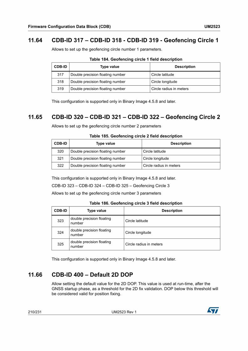
Firmware Configuration Data Block (CDB) UM2523
210/231 UM2523 Rev 1
11.64 CDB-ID 317 – CDB-ID 318 - CDB-ID 319 - Geofencing Circle 1
Allows to set up the geofencing circle number 1 parameters.
This configuration is supported only in Binary Image 4.5.8 and later.
11.65 CDB-ID 320 – CDB-ID 321 – CDB-ID 322 – Geofencing Circle 2
Allows to set up the geofencing circle number 2 parameters
This configuration is supported only in Binary Image 4.5.8 and later.
CDB-ID 323 – CDB-ID 324 – CDB-ID 325 – Geofencing Circle 3
Allows to set up the geofencing circle number 3 parameters
This configuration is supported only in Binary Image 4.5.8 and later.
11.66 CDB-ID 400 – Default 2D DOP
Allow setting the default value for the 2D DOP. This value is used at run-time, after the GNSS startup phase, as a threshold for the 2D fix validation. DOP below this threshold will be considered valid for position fixing.
Table 184. Geofencing circle 1 field description
CDB-ID Type value Description
317 Double precision floating number Circle latitude
318 Double precision floating number Circle longitude
319 Double precision floating number Circle radius in meters
Table 185. Geofencing circle 2 field description
CDB-ID Type value Description
320 Double precision floating number Circle latitude
321 Double precision floating number Circle longitude
322 Double precision floating number Circle radius in meters
Table 186. Geofencing circle 3 field description
CDB-ID Type value Description
323double precision floating number
Circle latitude
324double precision floating number
Circle longitude
325double precision floating number
Circle radius in meters

UM2523 Rev 1 211/231
UM2523 Firmware Configuration Data Block (CDB)
230
System reboot needed to have new setting in use.
11.67 CDB-ID 401 – Default 3D DOP
Allow setting the default value for the 3D DOP. This value is used at run-time, after the GNSS startup phase, as a threshold for the 3D fix validation. DOP below this threshold will be considered valid for position fixing.
System reboot needed to have new setting in use.
11.68 CDB-ID 402 – Startup 2D DOP
Allow setting the startup value for the 2D DOP. This value is used during the GNSS startup phase as a threshold for the 2D fix validation. DOP below this threshold will be considered valid for position fixing.
System reboot needed to have new setting in use.
11.69 CDB-ID 403 – Startup 3D DOP
Allow setting the startup value for the 3D DOP. This value is used during the GNSS startup phase as a threshold for the 3D fix validation. DOP below this threshold will be considered valid for position fixing.
System reboot needed to have new setting in use.
11.70 CDB-ID 500 – Text message
Allow setting a text message which is sent (if enabled – see bit9 of CDB-ID 200 parameter) at startup over the NMEA port. The user is free to use this text as product name or as specific configuration marker.
System reboot needed to have new setting in use.

Acronyms and definitions UM2523
212/231 UM2523 Rev 1
Appendix A Acronyms and definitions
Table 187 lists the acronyms and definitions used in this document.
Table 187. Acronyms and definitions
Keyword Definition
Accuracy Deviation of a GPS-based calculated position from the true position
ADC Analogue to Digital Converter
AlmanacContains the information about all available satellites, their orbit data and time of their clocks.
ANF Adaptive Notch Filter
Azim Azimuth - Angular distance from a reference
Bank Swap Exchanging two memory banks for storage of data
BAUD rateTransmission Rate Measure for the effective transmission of data content. (may differ from Bits/sec).
BEIDOU China’s regional navigation satellite system
ChecksumCalculated from the transmitted characters of a message by “ex-OR”ing the 8 bit character values excluding delimiters $ and *
CN0 Carrier to Noise Ratio - Identifies the quality of a received signal
Cold StartStart Condition for a GPS system having no position nor time. Almanac and Ephemeris is not available, too.
BeiDou China’s global navigation satellite system (also known as Beidou-2, BD2)
Dead ReckoningSensor based process to determine the movement of a mobile unit, utilizing Gyro, Odometer and Wheel Pulses.
Delimiter
(within NMEA 0183)
ASCII “$” to indicate Address Field
ASCII “,” to indicate Data Field
ASCII “*” to indicate Checksum Field
DGPSDifferential GPS - GPS Augmentation System providing the accurate location of a Reference Station to reduce system errors.
EGNOS European Geostationary Navigation Overlay System
ElevElevation - Angle between a high level or non-earth bound point and the horizontal plane of the viewer.
EphemerisEphemeris Data is transmitted by each satellite and contains current and predicted satellite position.
FDAFailure Detection Algorithm - Specific Algorithm to detect failures in position calculation
FDE False Detection Exclusion
GALILEO Europe’s global navigation satellite system
GDOPGeometric Dilution Of Position - Quality value representing all geometry based error factors in a system.

UM2523 Rev 1 213/231
UM2523 Acronyms and definitions
230
GNSSGlobal Navigation Satellite System - Satellite based system to calculate the position of the Teseo on the earth surface.
GPS Global Positioning System - United States Satellite Navigation System
GPS Library STMicroelectronics C-Library containing all GPS relevant Functions
Gyro Gyroscope - Sensor to determine rotational movements
HDOPHorizontal Dilution Of Precision - Quality value representing all 2D plane geometry based error factors in a system.
Hot StartStart Condition for a GPS System having position, time, Almanac and Ephemeris already available. High time accuracy is required.
IMU Inertial Measurement Unit
LatLatitude - Angular difference of a given position to the Equator. Values include 0°-90° either North or South
Lat-Ref Latitude Reference - Reference if a Latitude value is North or South
LongLongitude - Angular difference to a “reference” Longitude indicated as “000”. Values include 0°… 180° either West or East.
Long-RefLongitude Reference - Reference if a Longitude value is East or West of the “000” Meridian.
NMEANational Marine Electronics Association - United States Standards Organization For Marine Equipment
NMEA 0183National Marine Electronics Association - Standard for Interfacing Marine Electronics Devices
NVMNon Volatile Memory - Any type of memory that conserves data in the absence of regular supply voltage (includes battery buffered memories)
Proprietary MessageMessages within the scope of NMEA0183 which are not standardized. They start with $P and a 3 character identifier.
PRNPseudo Random Number - Satellite Specific 1023 Bit Number used for Spread Spectrum Modulation
RAIM Teseo Autonomous Integrity Monitoring
RF Radio Frequency - High Frequency for Reception with a RF-Teseo
RS232 IEEE Standard - Physical Layer Standard for Data Transmission
Sat-IDSatellite Identifier - Satellite specific Number used to generate the corresponding PRN code
SBASSatellite Based Augmentation System - GPS enhancement system based on geostationary satellites.
SPS Standard Positioning Service
Static Position FilteringAlgorithm to detect that the GPS Teseo doesn't move and position output is kept stable.
UTC Universal Time Coordinated
WAASWide Area Augmentation System - American GPS Augmentation System delivering accurate Ionosphere Data
Table 187. Acronyms and definitions (continued)
Keyword Definition

Acronyms and definitions UM2523
214/231 UM2523 Rev 1
A.1 Local geodetic datum tables
Warm StartStart Condition for a GPS system having current Almanac, position and time availability. Ephemeris are not available. Time needs to be available with reasonable accuracy (some seconds).
2D Fix Fix based on the use of 3 satellites
3D Fix Fix based on the use of 4 satellites
Table 187. Acronyms and definitions (continued)
Keyword Definition
Table 188. Africa geodetic datum
AFRICA
REGION CODECDB-ID VALUE
ADINDAN
MeanSolution (Ethiopia-Sudan) ADI-M 0
BurkinaFaso ADI-E 1
Cameroon ADI-F 2
Ethiopia ADI-A 3
Mali ADI-C 4
Senegal ADI-D 5
Sudan ADI-B 6
AFGOOYE
Somalia AFG 7
ARC_1950
Mean_Solution ARF-M 8
Botswana ARF-A 9
Burundi ARF-H 10
Lesotho ARF-B 11
Malawi ARF-C 12
Swaziland ARF-D 13
Zaire ARF-E 14
Zambia ARF-F 15
Zimbabwe ARF-G 16
ARC_1960

UM2523 Rev 1 215/231
UM2523 Acronyms and definitions
230
Mean_Solution ARS-M 17
Kenya ARS-A 18
Tanzania ARS-B 19
AYABELLE_LIGHTHOUSE
Djibouti PHA 20
BISSAU
Guinea-Bissau BID 21
CAPE
South_Africa CAP 22
CARTHAGE
Tunisia CGE 23
DABOLA
Guinea DAL 24
EUROPEAN_1950
Egypt EUR-F 73
Tunisia EUR-T 83
LEIGON
Ghana LEH 25
LIBERIA_1964
Liberia LIB 26
MASSAWA
Eritrea (Ethiopia) MAS 27
MERCHICH
Morocco MER 28
MINNA
Cameroon MIN-A 29
Nigeria MIN-B 30
M'PORALOKO
Table 188. Africa geodetic datum (continued)
AFRICA
REGION CODECDB-ID VALUE

Acronyms and definitions UM2523
216/231 UM2523 Rev 1
Gabon MPO 31
NORTH_SAHARA_1959
Algeria NSD 32
OLD_EGYPTIAN_1907
Egypt OEG 33
POINT_58
Mean_Solution (BurkinaFaso-Niger) PTB 34
POINTE_NOIRE_1948
Congo PTN 35
SCHWARZECK
Namibia SCK 36
SIERRA_LEONE_1960
SierraLeone SRL 37
VOIROL_1960
Algeria VOR 38
Table 188. Africa geodetic datum (continued)
AFRICA
REGION CODECDB-ID VALUE
Table 189. Asia geodetic datum
ASIA
REGION CODECDB-ID VALUE
AIN_EL_ABD_1970
Bahrain_Island AIN-A 39
Saudi_Arabia AIN-B 40
DJAKARTA(BATAVIA)
Sumatra (Indonesia) BAT 41
EUROPEAN_1950
Iran EUR-H 77

UM2523 Rev 1 217/231
UM2523 Acronyms and definitions
230
HONG_KONG_1963
Hong_Kong HKD 42
HU-TZU-SHAN
Taiwan HTN 43
INDIAN
Bangladesh IND-B 44
India-Nepal IND-I 45
INDIAN_1954
Thailand INF-A 46
INDIAN_1960
Vietnam (near_16DegNorth) ING-A 47
ConSonIsland (Vietnam) ING-B 48
INDIAN_1975
Thailand INH-A 49
Thailand INH-A1 50
INDONESIAN_1974
Indonesia IDN 51
KANDAWALA
SriLanka KAN 52
KERTAU_1948
WestMalaysia-Singapore KEA 53
KOREAN_1995
SouthKorea KGS 54
NAHRWAN
MasirahIsland (Oman) NAH-A 55
UnitedArabEmirates NAH-B 56
SaudiArabia NAH-C 57
OMAN
Table 189. Asia geodetic datum (continued)
ASIA
REGION CODECDB-ID VALUE

Acronyms and definitions UM2523
218/231 UM2523 Rev 1
Oman FAH 58
QATAR_NATIONAL
Qatar QAT 59
SOUTH_ASIA
Singapore SOA 60
TIMBALAI_1948
Brunei-East_Malaysia TIL 61
TOKYO
MeanSolution TOY-M 62
Japan TOY-A 63
Okinawa TOY-C 64
South Korea TOY-B 65
South Korea TOY-B1 66
Table 189. Asia geodetic datum (continued)
ASIA
REGION CODECDB-ID VALUE
Table 190. Australia geodetic datum
AUSTRALIA
REGION CODECDB-ID VALUE
AUSTRALIAN_1966
Australia-Tasmania AUA 67
AUSTRALIAN_1984
Australia-Tasmania AUG 68

UM2523 Rev 1 219/231
UM2523 Acronyms and definitions
230
Table 191. Europe geodetic datum
EUROPE
REGION CODECDB-ID VALUE
CO-ORDINATE SYSTEM 1937 OF ESTONIA
Estonia EST 69
EUROPEAN_1950
MeanSolution EUR-M 70
WesternEurope EUR-A 71
Cyprus EUR-E 72
Egypt EUR-F 73
England, ChannelIslands, Scotland, ShetlandIslands EUR-G 74
England, Ireland, Scotland, ShetlandIslands EUR-K 75
Greece EUR-B 76
Iran EUR-H 77
ItalySardinia EUR-I 78
ItalySicily EUR-J 79
Malta EUR-L 80
Norway, Finland EUR-C 81
Portugal, Spain EUR-D 82
Tunisia EUR-T 83
EUROPEAN_1979
MeanSolution EUS 84
HJORSEY_1955
Iceland HJO 85
IRELAND_1965
Ireland IRL 86
ORDNANCE SURVEY OF GREAT BRITAIN 1936
MeanSolution OGB-M 87
England OGB-A 88
England, IsleOfMan, Wales OGB-B 89
Scotland, ShetlandIslands OGB-C 90
Wales OGB-D 91

Acronyms and definitions UM2523
220/231 UM2523 Rev 1
ROME_1940
Sardinia MOD 92
S-42(PULKOVO_1942)
Hungary SPK-A 93
Poland SPK-B 94
Czechoslovakia* SPK-C 95
Latvia SPK-D 96
Kazakhstan SPK-E 97
Albania SPK-F 98
Romania SPK-G 99
S-JTSK
Czechoslovakia CCD 100
Table 191. Europe geodetic datum (continued)
EUROPE
REGION CODECDB-ID VALUE
Table 192. North America geodetic datum
NORTH AMERICA
REGION CODECDB-ID VALUE
CAPE_CANAVERAL
MeanSolution (Florida, Bahamas) CAC 101
NORTH AMERICAN 1927
MeanSolution NAS-C 102
WesternUnitedStates NAS-B 103
EasternUnitedStates NAS-A 104
Alaska (ExcludingAleutianIslands) NAS-D 105
AleutianIslands(East180°W) NAS-V 106
AleutianIslands(West180°W) NAS-W 107
Bahamas (Excluding San Salvador Island) NAS-Q 108

UM2523 Rev 1 221/231
UM2523 Acronyms and definitions
230
SanSalvadorIsland NAS-R 109
CanadaMeanSolution(Including Newfoundland) NAS-E 110
Alberta, BritishColumbia NAS-F 111
EasternCanada NAS-G 112
Manitoba, Ontario NAS-H 113
NorthwestTerritories, Saskatchewan NAS-I 114
Yukon NAS-J 115
CanalZone NAS-O 116
Caribbean NAS-P 117
CentralAmerica NAS-N 118
Cuba NAS-T 119
Greenland NAS-U 120
Mexico NAS-L 121
NORTH AMERICAN 1983
Alaska (ExcludingAleutianIslands) NAR-A 122
Aleutian Islands NAR-E 123
Canada NAR-B 124
CONUS NAR-C 125
Hawaii NAR-H 126
Mexico,Central America NAR-D 127
Table 192. North America geodetic datum (continued)
NORTH AMERICA
REGION CODECDB-ID VALUE
Table 193. South America geodetic datum
SOUTH AMERICA
REGION CODECDB-ID VALUE
BOGOTA OBSERVATORY
Colombia BOO 128

Acronyms and definitions UM2523
222/231 UM2523 Rev 1
CAMPO NCHAUSPE 1969
Argentina CAI 129
CHUA ASTRO
Paraguay CHU 130
CORREGO ALEGRE
Brazil COA 131
PROVISIONAL SOUTH AMERICAN 1956
MeanSolution PRP-M 132
Bolivia PRP-A 133
Northern Chile (near 19°S) PRP-B 134
Southern Chile (near 43°S) PRP-C 135
Colombia PRP-D 136
Ecuador PRP-E 137
Guyana PRP-F 138
Peru PRP-G 139
Venezuela PRP-H 140
PROVISIONAL SOUTH CHILEAN
Southern Chile (near 53°S) HIT 141
SOUTH AMERICAN 1969
MeanSolution SAN-M 142
Argentina SAN-A 143
Bolivia SAN-B 144
Brazil SAN-C 145
Chile SAN-D 146
Colombia SAN-E 147
Ecuador (Excluding Galapagos Islands) SAN-F 148
Baltra, Galapagos Islands SAN-J 149
Guyana SAN-G 150
Table 193. South America geodetic datum (continued)
SOUTH AMERICA
REGION CODECDB-ID VALUE
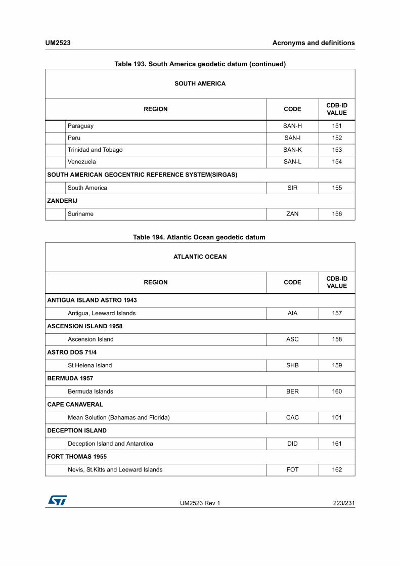
UM2523 Rev 1 223/231
UM2523 Acronyms and definitions
230
Paraguay SAN-H 151
Peru SAN-I 152
Trinidad and Tobago SAN-K 153
Venezuela SAN-L 154
SOUTH AMERICAN GEOCENTRIC REFERENCE SYSTEM(SIRGAS)
South America SIR 155
ZANDERIJ
Suriname ZAN 156
Table 193. South America geodetic datum (continued)
SOUTH AMERICA
REGION CODECDB-ID VALUE
Table 194. Atlantic Ocean geodetic datum
ATLANTIC OCEAN
REGION CODECDB-ID VALUE
ANTIGUA ISLAND ASTRO 1943
Antigua, Leeward Islands AIA 157
ASCENSION ISLAND 1958
Ascension Island ASC 158
ASTRO DOS 71/4
St.Helena Island SHB 159
BERMUDA 1957
Bermuda Islands BER 160
CAPE CANAVERAL
Mean Solution (Bahamas and Florida) CAC 101
DECEPTION ISLAND
Deception Island and Antarctica DID 161
FORT THOMAS 1955
Nevis, St.Kitts and Leeward Islands FOT 162

Acronyms and definitions UM2523
224/231 UM2523 Rev 1
GRACIOSA BASE SW 1948
Faial, Graciosa, Pico, SaoJorge and Terceira Islands (Azores) GRA 163
HJORSEY 1955
Iceland HJO 85
ISTS 061 ASTRO 1968
South Georgia Island ISG 164
L.C. 5 ASTRO 1961
Cayman Brac Island LCF 165
MONTSERRAT ISLAND ASTRO 1958
Montserrat and Leeward Islands ASM 166
NAPARIMA,BWI
Trinidad and Tobago NAP 167
OBSERVATORIO METEOROLOGICO 1939
Corvo and Flores Islands (Azores) FLO 168
PICO DE LAS NIEVES
Canary Islands PLN 169
PORTO SANTO 1936
Porto Santo and Madeira Islands POS 170
PUERTO RICO
Puerto Rico and Virgin Islands PUR 171
QORNOQ
South Greenland QUO 172
SAO BRAZ
Sao Miguel and Santa Maria Islands (Azores) SAO 173
SAPPER HILL 1943
East Falkland Island SAP 174
SELVAGEM GRANDE 1938
Table 194. Atlantic Ocean geodetic datum (continued)
ATLANTIC OCEAN
REGION CODECDB-ID VALUE
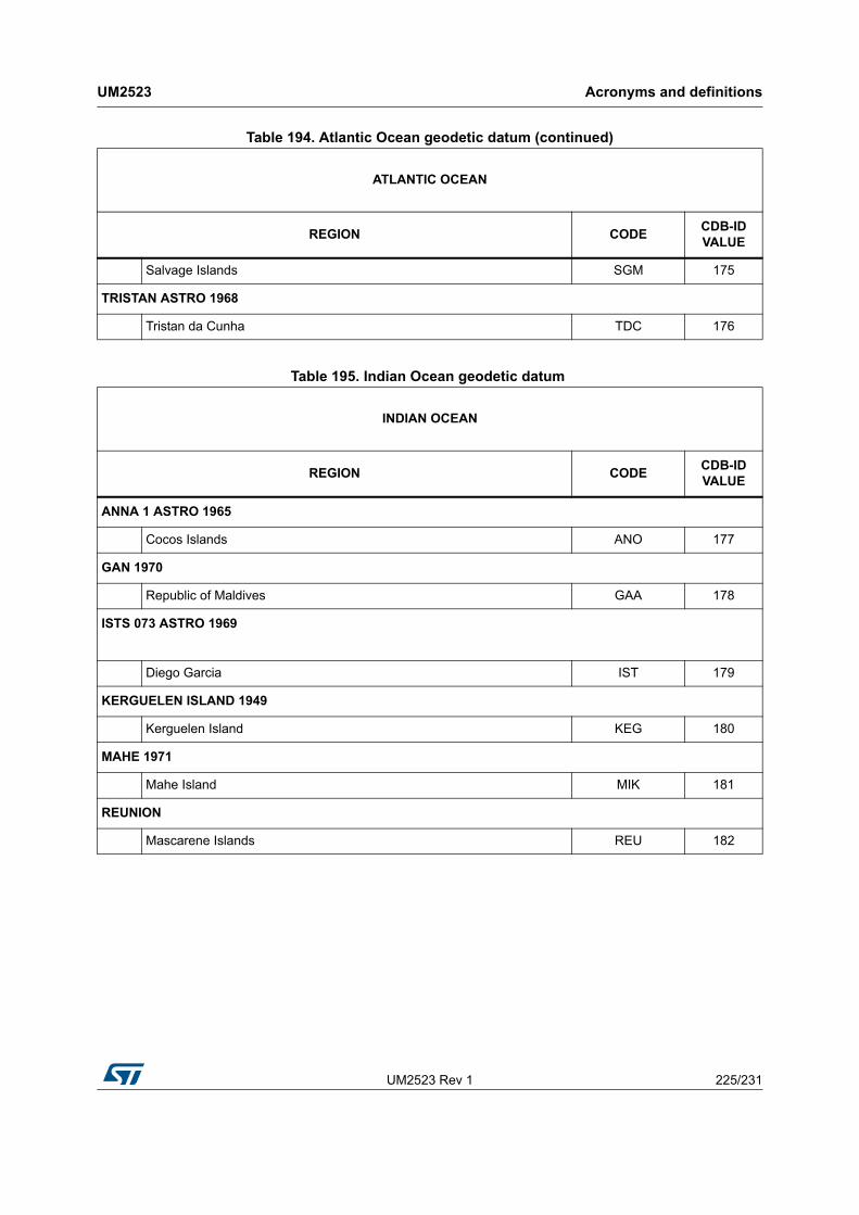
UM2523 Rev 1 225/231
UM2523 Acronyms and definitions
230
Salvage Islands SGM 175
TRISTAN ASTRO 1968
Tristan da Cunha TDC 176
Table 194. Atlantic Ocean geodetic datum (continued)
ATLANTIC OCEAN
REGION CODECDB-ID VALUE
Table 195. Indian Ocean geodetic datum
INDIAN OCEAN
REGION CODECDB-ID VALUE
ANNA 1 ASTRO 1965
Cocos Islands ANO 177
GAN 1970
Republic of Maldives GAA 178
ISTS 073 ASTRO 1969
Diego Garcia IST 179
KERGUELEN ISLAND 1949
Kerguelen Island KEG 180
MAHE 1971
Mahe Island MIK 181
REUNION
Mascarene Islands REU 182

Acronyms and definitions UM2523
226/231 UM2523 Rev 1
Table 196. Pacific Ocean geodetic datum
PACIFIC OCEAN
REGION CODECDB-ID VALUE
AMERICAN SAMOA 1962
American Samoa Islands AMA 183
ASTRO BEACON “E” 1945
Iwo Jima ATF 184
ASTRO TERN ISLAND (FRIG) 1961
Tern Island TRN 185
ASTRONOMICAL STATION 1952
Marcus Island ASQ 186
BELLEVUE (IGN)
Efate and Erromango Islands IBE 187
CANTON ASTRO 1966
Phoenix Islands CAO 188
CHATHAM ISLAND ASTRO 1971
Chatham Island (New Zealand) CHI 189
DOS 1968
Gizo Island (New Georgia Islands) GIZ 190
EASTER ISLAND 1967
Easter Island EAS 191
GEODETIC DATUM 1949
New Zealand GEO 192
GUAM 1963
Guam GUA 193
GUX l ASTRO
Guadalcanal Island DOB 194
INDONESIAN 1974
Indonesia IDN 51
JOHNSTON ISLAND 1961

UM2523 Rev 1 227/231
UM2523 Acronyms and definitions
230
Johnston Island JOH 195
KUSAIE ASTRO 1951
CarolineIslands, Fed.States of Micronesia KUS 196
LUZON
Philippines (Excluding Mindanao Island) LUZ-A 197
Mindanao Island LUZ-B 198
MIDWAY ASTRO 1961
Midway Islands MID_A 199
Midway Islands MID_B 200
OLD_HAWAIIAN
Mean Solution OHA-M 201
Hawaii OHA-A 202
Kauai OHA-B 203
Maui OHA-C 204
Oahu OHA-D 205
OLD HAWAIIAN
Mean Solution OHI-M 206
Hawaii OHI-A 207
Kauai OHI-B 208
Maui OHI-C 209
Oahu OHI-D 210
PITCAIRN ASTRO 1967
Pitcairn Island PIT 211
SANTO (DOS) 1965
Espirito Santo Island SAE 212
VITI LEVU 1916
VitiLevuIsland (Fiji Islands) MVS 213
Table 196. Pacific Ocean geodetic datum (continued)
PACIFIC OCEAN
REGION CODECDB-ID VALUE

Acronyms and definitions UM2523
228/231 UM2523 Rev 1
WAKE-ENIWETOK 1960
Marshall Islands ENW 214
WAKE ISLAND ASTRO 1952
Wake Atoll WAK 215
Table 196. Pacific Ocean geodetic datum (continued)
PACIFIC OCEAN
REGION CODECDB-ID VALUE
Table 197. Non-Satellite Derived Transformation Parameter geodetic datum
Non-Satellite Derived Transformation Parameter
REGION CODECDB-ID VALUE
BUKIT RIMPAH
Bangka and Belitung Islands (Indonesia) BUR 216
CAMP AREA ASTRO
Camp McMurdo Area, Antarctica CAZ 217
EUROPEAN 1950
Iraq, Israel, Jordan, Kuwait, Lebanon, Saudi Arabia, Syria EUR-S 218
GUNUNG SEGARA
Kalimantam (Indonesia) GSE 219
HERAT NORTH
Afghanistan HEN 220
HERMANNSKOGEL
Slovenia, Croatia, Bosnia and Herzegovina, Serbia HER 221
INDIAN
Pakistan IND_P 222
PULKOVO 1942
Russia PUK 223
TANANARIVE OBSERVATORY 1925
Madagascar TAN 224

UM2523 Rev 1 229/231
UM2523 Acronyms and definitions
230
VOIROL 1874
Tunisia, Algeria VOI 225
YACARE
Uruguay YAC 226
Table 197. Non-Satellite Derived Transformation Parameter geodetic datum (continued)
Non-Satellite Derived Transformation Parameter
REGION CODECDB-ID VALUE
Table 198. Terrestrial Reference Systems geodetic datum
Terrestrial Reference Systems
CODECDB-ID VALUE
GLONASS
PZ90.2 PZ90_2 227
PZ90.11 PZ90_11 254

Revision history UM2523
230/231 UM2523 Rev 1
Revision history
Table 199. Document revision history
Date Revision Changes
17-Jan-2019 1 Initial release.

UM2523 Rev 1 231/231
UM2523
231
IMPORTANT NOTICE – PLEASE READ CAREFULLY
STMicroelectronics NV and its subsidiaries (“ST”) reserve the right to make changes, corrections, enhancements, modifications, and improvements to ST products and/or to this document at any time without notice. Purchasers should obtain the latest relevant information on ST products before placing orders. ST products are sold pursuant to ST’s terms and conditions of sale in place at the time of order acknowledgement.
Purchasers are solely responsible for the choice, selection, and use of ST products and ST assumes no liability for application assistance or the design of Purchasers’ products.
No license, express or implied, to any intellectual property right is granted by ST herein.
Resale of ST products with provisions different from the information set forth herein shall void any warranty granted by ST for such product.
ST and the ST logo are trademarks of ST. All other product or service names are the property of their respective owners.
Information in this document supersedes and replaces information previously supplied in any prior versions of this document.
© 2019 STMicroelectronics – All rights reserved
Related Documents