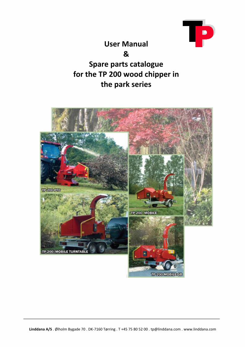
Linddana A/S . Ølholm Bygade 70 . DK-7160 Tørring . T +45 75 80 52 00 . [email protected] . www.linddana.com User Manual & Spare parts catalogue for the TP 200 wood chipper in the park series

Welcome message from author
This document is posted to help you gain knowledge. Please leave a comment to let me know what you think about it! Share it to your friends and learn new things together.
Transcript
Linddana A/S . Ølholm Bygade 70 . DK-7160 Tørring . T +45 75 80 52 00 . [email protected] . www.linddana.com
User Manual &
Spare parts catalogue for the TP 200 wood chipper in
the park series
Linddana A/S . Ølholm Bygade 70 . DK-7160 Tørring . T +45 75 80 52 00 . [email protected] . www.linddana.com User instructions: TP 200 from 02.11.2015 ©Copyright 2008
2
1 Introduction Congratulations on your new TP wood chipper. Linddana produces TP wood chippers of the finest quality by using the most modern production technologies, i.e. laser cutting, CNC technology and robot technology in bright and open production facilities. For safety reasons and in order to get maximum pleasure from the wood cutter, it is important to read these instructions before use. The user manual explains about safety, use and maintenance so that the work with the wood chipper will be safe and profitable. This manual has been translated from Danish. Linddana A/S
Jørgen Due Jensen, Managing director Your distributor is always available with spare parts, advice and guidance. Distributor stamp
Linddana A/S . Ølholm Bygade 70 . DK-7160 Tørring . T +45 75 80 52 00 . [email protected] . www.linddana.com User instructions: TP 200 from 02.11.2015 ©Copyright 2008
3
2 EU declaration of conformity. Manufacturer: LINDDANA A/S, Ølholm Bygade 70, Ølholm, 7160 Tørring, Denmark hereby declares that ______________________________________________ Wood chipper: is in concordance with the provisions of the Machine Directive (Directive 06/42/EC) and with the national legislation which translates this directive; is in concordance with the following other EC Directives: 2000/14/EC Furthermore it is stated that EN 13525 (harmonised standard), has been used. Title: Managing director Name: Jørgen Due Jensen
Ølholm, 02 November 2015
Linddana A/S . Ølholm Bygade 70 . DK-7160 Tørring . T +45 75 80 52 00 . [email protected] . www.linddana.com User instructions: TP 200 from 02.11.2015 ©Copyright 2008
4
3 Table of content 1 Introduction .................................................................................................... 2 2 EU declaration of conformity. .......................................................................... 3 3 Table of content .............................................................................................. 4 4 Use .................................................................................................................. 5 5 Mounting instructions ..................................................................................... 6
5.1 Before use ............................................................................................................................ 6 5.2 Mounting instruction ........................................................................................................... 8
6 Safety instructions........................................................................................... 9 6.1 Safety regulations ................................................................................................................ 9 6.2 Pictograms used ................................................................................................................. 11 6.3 Noise level .......................................................................................................................... 12 6.4 Environmental instructions ............................................................................................... 12
7 Operation of the machine ............................................................................. 13 7.1 Table 1 Regulating the number of revolutions for the retract rollers .............................. 14
8 Maintenance ................................................................................................. 15 8.1 Maintenance schedule ....................................................................................................... 15 8.2 Lubrication and oil ............................................................................................................. 16 8.3 Maintenance of the retract rollers .................................................................................... 17 8.4 Changing worn parts .......................................................................................................... 18 8.5 Grinding of knives .............................................................................................................. 24
9 Special instruction for TP 200 MOBILE ........................................................... 25 10 Special instruction for TP 200 MOBILE TURNTABLE .................................... 25 11 Hydraulics diagram, TP 200 without revolution guard ................................ 27 12 Hydraulics diagram TP 200 with revolution guard ...................................... 27 13 Instruction for revolution guard TP PILOT .................................................. 28
13.1 Overall operation ............................................................................................................... 28 13.2 Programming ..................................................................................................................... 30 13.3 Mounting............................................................................................................................ 34 13.4 Technical data .................................................................................................................... 35
14 Troubleshooting for wood chipper TP 200 .................................................. 36 15 Warranty obligation for wood chipper ....................................................... 37 16 Technical data wood chipper ..................................................................... 39 17 Accessories ................................................................................................ 41 18 Spare parts catalogue ................................................................................. 41
Linddana A/S . Ølholm Bygade 70 . DK-7160 Tørring . T +45 75 80 52 00 . [email protected] . www.linddana.com User instructions: TP 200 from 02.11.2015 ©Copyright 2008
5
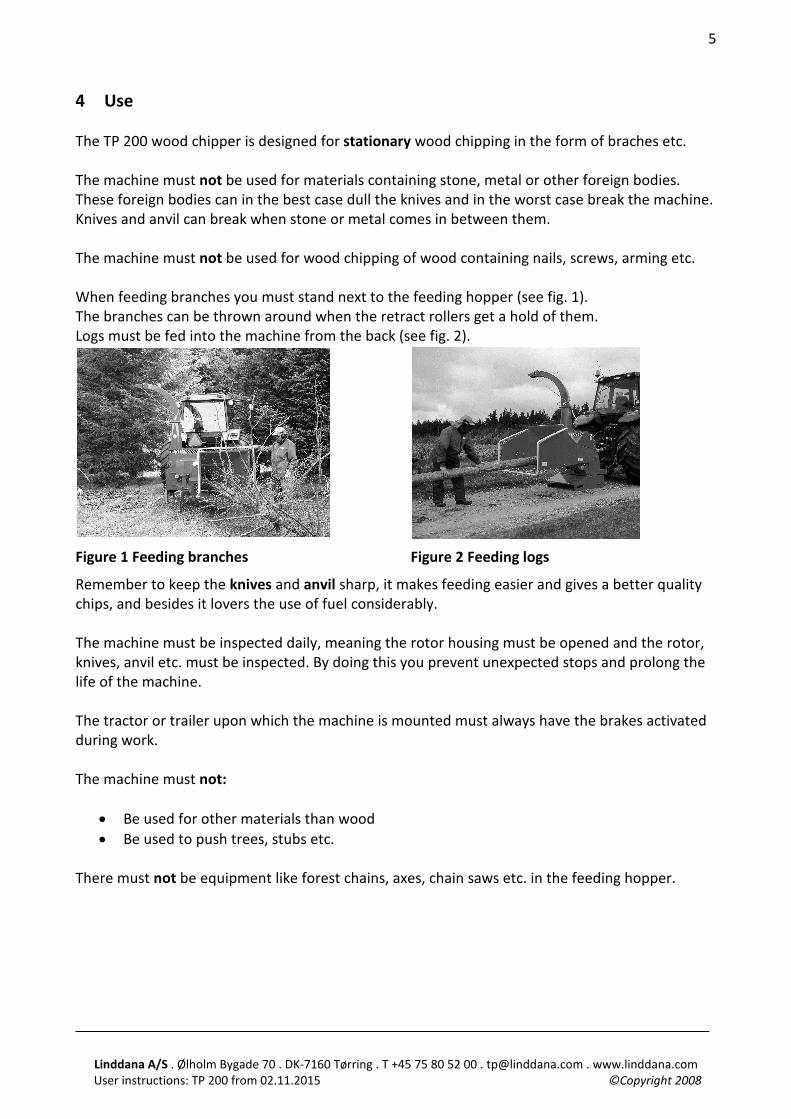
4 Use The TP 200 wood chipper is designed for stationary wood chipping in the form of braches etc. The machine must not be used for materials containing stone, metal or other foreign bodies. These foreign bodies can in the best case dull the knives and in the worst case break the machine. Knives and anvil can break when stone or metal comes in between them. The machine must not be used for wood chipping of wood containing nails, screws, arming etc. When feeding branches you must stand next to the feeding hopper (see fig. 1). The branches can be thrown around when the retract rollers get a hold of them. Logs must be fed into the machine from the back (see fig. 2).
Figure 1 Feeding branches Figure 2 Feeding logs
Remember to keep the knives and anvil sharp, it makes feeding easier and gives a better quality chips, and besides it lovers the use of fuel considerably. The machine must be inspected daily, meaning the rotor housing must be opened and the rotor, knives, anvil etc. must be inspected. By doing this you prevent unexpected stops and prolong the life of the machine. The tractor or trailer upon which the machine is mounted must always have the brakes activated during work. The machine must not:
• Be used for other materials than wood • Be used to push trees, stubs etc.
There must not be equipment like forest chains, axes, chain saws etc. in the feeding hopper.
Linddana A/S . Ølholm Bygade 70 . DK-7160 Tørring . T +45 75 80 52 00 . [email protected] . www.linddana.com User instructions: TP 200 from 02.11.2015 ©Copyright 2008
6
Figure 4 Lifting with a fork lift truck
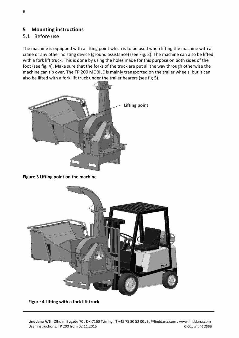
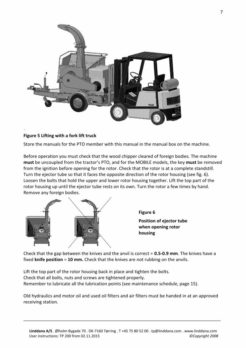
5 Mounting instructions 5.1 Before use The machine is equipped with a lifting point which is to be used when lifting the machine with a crane or any other hoisting device (ground assistance) (see Fig. 3). The machine can also be lifted with a fork lift truck. This is done by using the holes made for this purpose on both sides of the foot (see fig. 4). Make sure that the forks of the truck are put all the way through otherwise the machine can tip over. The TP 200 MOBILE is mainly transported on the trailer wheels, but it can also be lifted with a fork lift truck under the trailer bearers (see fig 5).
Figure 3 Lifting point on the machine
Lifting point
Linddana A/S . Ølholm Bygade 70 . DK-7160 Tørring . T +45 75 80 52 00 . [email protected] . www.linddana.com User instructions: TP 200 from 02.11.2015 ©Copyright 2008
7
Figure 5 Lifting with a fork lift truck
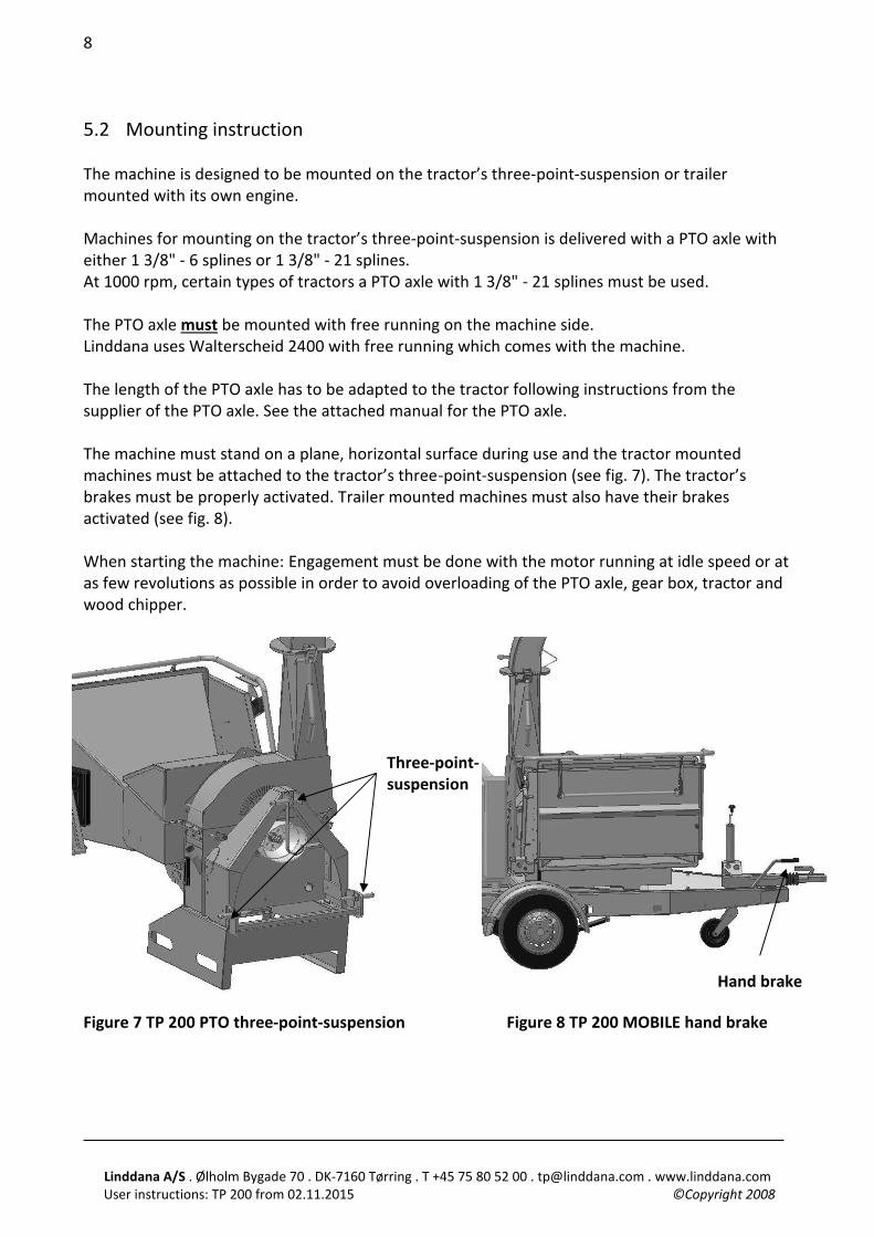
Store the manuals for the PTO member with this manual in the manual box on the machine. Before operation you must check that the wood chipper cleared of foreign bodies. The machine must be uncoupled from the tractor’s PTO, and for the MOBILE models, the key must be removed from the ignition before opening for the rotor. Check that the rotor is at a complete standstill. Turn the ejector tube so that it faces the opposite direction of the rotor housing (see fig. 6). Loosen the bolts that hold the upper and lower rotor housing together. Lift the top part of the rotor housing up until the ejector tube rests on its own. Turn the rotor a few times by hand. Remove any foreign bodies.
Check that the gap between the knives and the anvil is correct = 0.5-0.9 mm. The knives have a fixed knife position = 10 mm. Check that the knives are not rubbing on the anvils. Lift the top part of the rotor housing back in place and tighten the bolts. Check that all bolts, nuts and screws are tightened properly. Remember to lubricate all the lubrication points (see maintenance schedule, page 15). Old hydraulics and motor oil and used oil filters and air filters must be handed in at an approved receiving station.
Figure 6
Position of ejector tube when opening rotor housing
Linddana A/S . Ølholm Bygade 70 . DK-7160 Tørring . T +45 75 80 52 00 . [email protected] . www.linddana.com User instructions: TP 200 from 02.11.2015 ©Copyright 2008
8
5.2 Mounting instruction The machine is designed to be mounted on the tractor’s three-point-suspension or trailer mounted with its own engine. Machines for mounting on the tractor’s three-point-suspension is delivered with a PTO axle with either 1 3/8" - 6 splines or 1 3/8" - 21 splines. At 1000 rpm, certain types of tractors a PTO axle with 1 3/8" - 21 splines must be used. The PTO axle must be mounted with free running on the machine side. Linddana uses Walterscheid 2400 with free running which comes with the machine. The length of the PTO axle has to be adapted to the tractor following instructions from the supplier of the PTO axle. See the attached manual for the PTO axle. The machine must stand on a plane, horizontal surface during use and the tractor mounted machines must be attached to the tractor’s three-point-suspension (see fig. 7). The tractor’s brakes must be properly activated. Trailer mounted machines must also have their brakes activated (see fig. 8). When starting the machine: Engagement must be done with the motor running at idle speed or at as few revolutions as possible in order to avoid overloading of the PTO axle, gear box, tractor and wood chipper.
Figure 7 TP 200 PTO three-point-suspension Figure 8 TP 200 MOBILE hand brake
Hand brake
Three-point-suspension
Linddana A/S . Ølholm Bygade 70 . DK-7160 Tørring . T +45 75 80 52 00 . [email protected] . www.linddana.com User instructions: TP 200 from 02.11.2015 ©Copyright 2008
9
6 Safety instructions 6.1 Safety regulations
• Use hearing protectors, safety goggles or a similar eye protection, close fitting safety clothing and safety shoes.
• When working near roads it can be prudent to wear a west which reflects the light to be more visible to the other road-users. The displaying of signs must be in accordance with the Road Traffic Act.
• Minimum age for users of the machine is 18, for training and under surveillance from an adult the age is 16.
• During operation, all body parts must be kept away from the feeding hopper and any moveable parts of the machine.
• Always stand next to the feeding hopper during feeding of the machine. Always observe the terrain conditions around the machine. It can be dangerous to fall near the machine!
• Before starting the machine check that the safety devices are working properly. Especially the stop and return functions on the operation bow.
• The machine must not be started without the ejector tube mounted to the machine. • Never use the machine in closed or poorly ventilated spaces, because of the danger of
carbon monoxide poisoning. • The top part of the machine as well as all other shielding must not be opened/removed
before the rotor disc is completely immovable and the tractor’s motor is stopped. • Always stop the machine and the tractor during inspections, service or repairs. The
machine must be uncoupled from the tractor’s PTO. • Tractor mounted machines have to be on the ground before service or repairs are done. • Always remove the keys from the machine and/or the tractor before leaving it. • After maintenance and repairs, the machine must not be started before all bolts are
tightened and all safety devices are mounted. • Three-point mounted machines must be coupled to the tractor’s three-point- suspension
before use. • The maximum rpm for the machine (1000 rpm) must not be superseded. • The transmission axle’s tube shielding and covering must always be intact. Safety chains on
the transmission axle have to be properly mounted. • The length of the PTO axle has to be adapted to the tractor according to the
recommendations from the supplier of the PTO axle. • The ejector tube must not point towards people or areas where there are people. There is
a safety distance of 20 m. in the direction where the chips are thrown. • AT DANGER: PUT THE OPERATION BOW IN NEUTRAL (See fig. 10)
Linddana A/S . Ølholm Bygade 70 . DK-7160 Tørring . T +45 75 80 52 00 . [email protected] . www.linddana.com User instructions: TP 200 from 02.11.2015 ©Copyright 2008
10
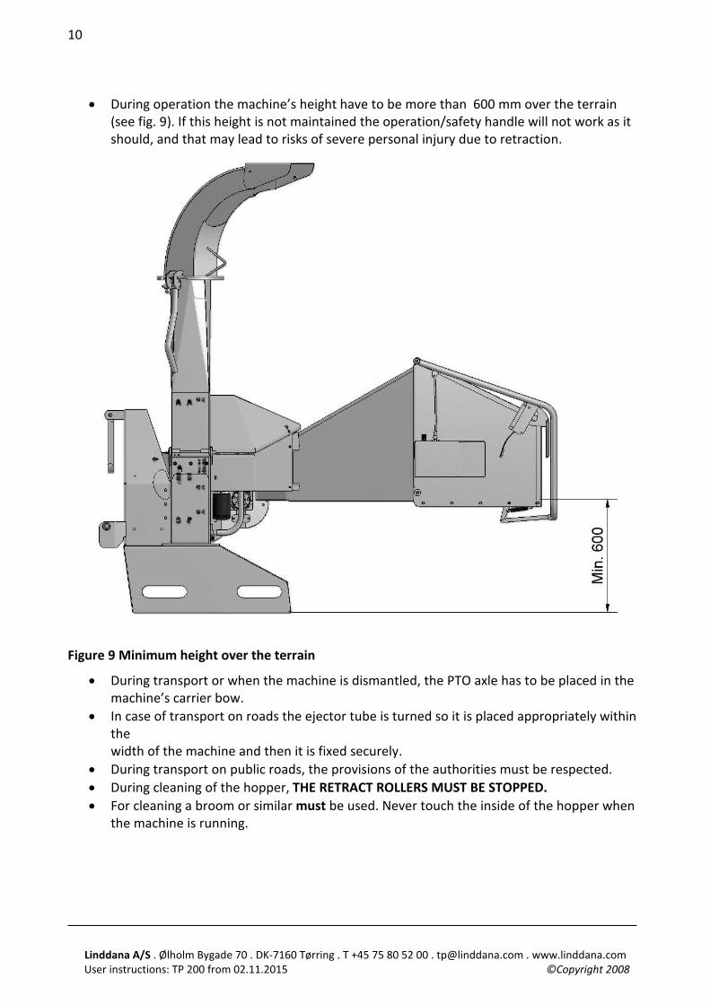
• During operation the machine’s height have to be more than 600 mm over the terrain (see fig. 9). If this height is not maintained the operation/safety handle will not work as it should, and that may lead to risks of severe personal injury due to retraction.
Figure 9 Minimum height over the terrain
• During transport or when the machine is dismantled, the PTO axle has to be placed in the machine’s carrier bow.
• In case of transport on roads the ejector tube is turned so it is placed appropriately within the width of the machine and then it is fixed securely.
• During transport on public roads, the provisions of the authorities must be respected. • During cleaning of the hopper, THE RETRACT ROLLERS MUST BE STOPPED. • For cleaning a broom or similar must be used. Never touch the inside of the hopper when
the machine is running.
Linddana A/S . Ølholm Bygade 70 . DK-7160 Tørring . T +45 75 80 52 00 . [email protected] . www.linddana.com User instructions: TP 200 from 02.11.2015 ©Copyright 2008
11
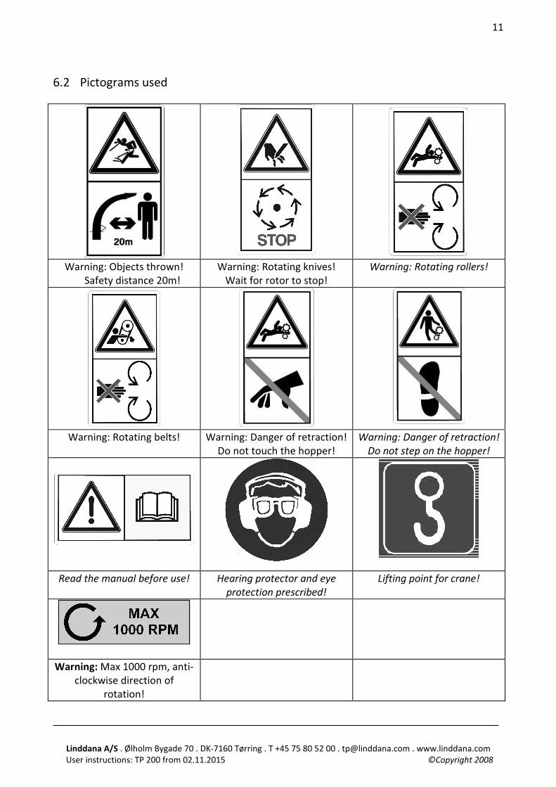
6.2 Pictograms used
Warning: Objects thrown!
Safety distance 20m! Warning: Rotating knives!
Wait for rotor to stop! Warning: Rotating rollers!
Warning: Rotating belts! Warning: Danger of retraction!
Do not touch the hopper! Warning: Danger of retraction!
Do not step on the hopper!
Read the manual before use! Hearing protector and eye protection prescribed!
Lifting point for crane!
Warning: Max 1000 rpm, anti-clockwise direction of
rotation!
Linddana A/S . Ølholm Bygade 70 . DK-7160 Tørring . T +45 75 80 52 00 . [email protected] . www.linddana.com User instructions: TP 200 from 02.11.2015 ©Copyright 2008
12
6.3 Noise level The sound effect level and the sound pressure level from the TP 200 PTO have been measured during use at 1000 rpm on the rotor disc, powered by a tractor. The sound effect level and the sound pressure level from the TP 200 MOBILE have been measured during use at 1000 rpm on the rotor disc, powered by the Hatz 3L41C motor engine. The measurements have been conducted according to test provisions Directive 2000/14/EC, 3. July 2000 EN ISO 3744, 1995 ISO 11201, 1995 ISO 4871, 19. March 1997 EN 13525, 17. February 2005 The warranty sound effect level which will be given by the manufacturer according to directive 2000/14/EC are as follows: TP 200 PTO: 125 dB (A) re.1pW. TP 200 MOBILE: 125 dB (A) re.1pW. The machine’s sound pressure level at the operator’s seat is measured according to ISO 11201 at: TP 200 PTO: 104 dB (A) TP 200 MOBILE: 107 dB (A) The above mentioned values have the common uncertainty for the method of measuring and the estimated variation in a product line for the type of machine. Detailed information on the measurements and results as well as estimation of uncertainty are found in a thorough report which can be given out on demand. The sound level is of such a character that hearing protectors are prescribed during use of the machine. 6.4 Environmental instructions When changing hydraulic oil or engine oil, oil and used oil filters and air filters must be handed in at an approved receiving station. Oil spills must be avoided as much as possible. At oil spills, the spilled oil must be cleaned up and handed in at an approved receiving station. Worn out parts must be disposed of for recycling. When the machine is worn out it must be disposed of properly. Hydraulic oil and engine oil must be drained and handed in at an approved receiving station with oil filters and air filters. The rest of the machine must be disposed of for recycling.
Linddana A/S . Ølholm Bygade 70 . DK-7160 Tørring . T +45 75 80 52 00 . [email protected] . www.linddana.com User instructions: TP 200 from 02.11.2015 ©Copyright 2008
13
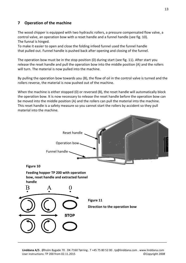
7 Operation of the machine The wood chipper is equipped with two hydraulic rollers, a pressure compensated flow valve, a control valve, an operation bow with a reset handle and a funnel handle (see fig. 10). The funnal is hinged. To make it easier to open and close the folding infeed funnel used the funnel handle that pulled out. Funnel handle is pushed back after opening and closing of the funnel. The operation bow must be in the stop position (0) during start (see fig. 11). After start you release the reset handle and pull the operation bow into the middle position (A) and the rollers will turn. The material is now pulled into the machine. By pulling the operation bow towards you (B), the flow of oil in the control valve is turned and the rollers reverse, the material is now pushed out of the machine. When the machine is either stopped (0) or reversed (B), the reset handle will automatically block the operation bow. It is now necessary to release the reset handle before the operation bow can be moved into the middle position (A) and the rollers can pull the material into the machine. This reset handle is a safety measure so you cannot start the rollers by accident so they pull material into the machine.
Figure 10
Feeding hopper TP 200 with operation bow, reset handle and extracted funnel handle
Figure 11
Direction to the operation bow
Operation bow
Reset handle
Funnel handle
Linddana A/S . Ølholm Bygade 70 . DK-7160 Tørring . T +45 75 80 52 00 . [email protected] . www.linddana.com User instructions: TP 200 from 02.11.2015 ©Copyright 2008
14
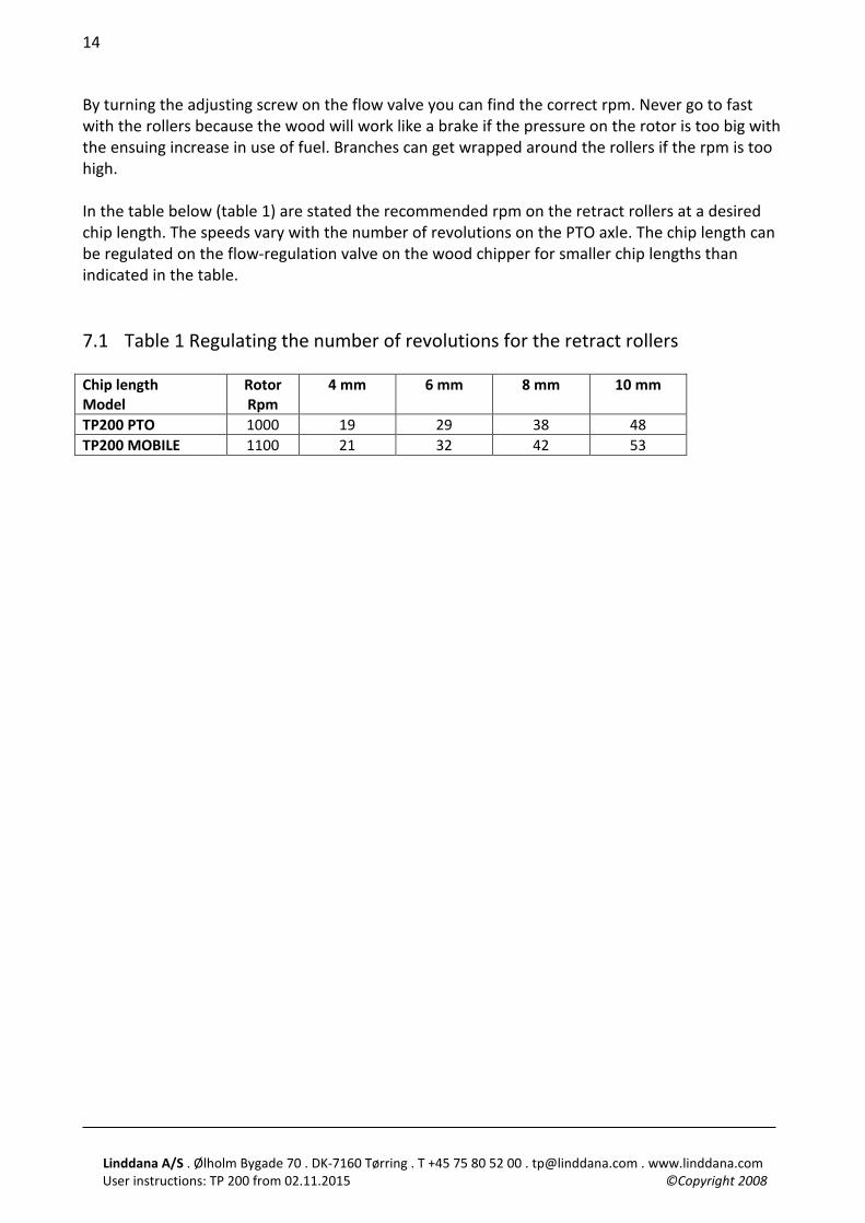
By turning the adjusting screw on the flow valve you can find the correct rpm. Never go to fast with the rollers because the wood will work like a brake if the pressure on the rotor is too big with the ensuing increase in use of fuel. Branches can get wrapped around the rollers if the rpm is too high. In the table below (table 1) are stated the recommended rpm on the retract rollers at a desired chip length. The speeds vary with the number of revolutions on the PTO axle. The chip length can be regulated on the flow-regulation valve on the wood chipper for smaller chip lengths than indicated in the table. 7.1 Table 1 Regulating the number of revolutions for the retract rollers Chip length Model
Rotor Rpm
4 mm 6 mm 8 mm 10 mm
TP200 PTO 1000 19 29 38 48 TP200 MOBILE 1100 21 32 42 53
Linddana A/S . Ølholm Bygade 70 . DK-7160 Tørring . T +45 75 80 52 00 . [email protected] . www.linddana.com User instructions: TP 200 from 02.11.2015 ©Copyright 2008
15
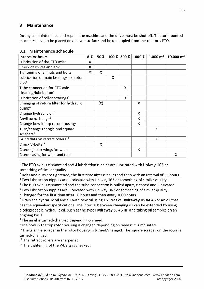
8 Maintenance During all maintenance and repairs the machine and the drive must be shut off. Tractor mounted machines have to be placed on an even surface and be uncoupled from the tractor’s PTO. 8.1 Maintenance schedule Interval=> hours 8 6 50 6 100 6 200 6 1000 6 1.000 m3 10.000 m3 Lubrication of the PTO axle1 X Check of knives and anvil X Tightening of all nuts and bolts2 (X) X Lubrication of main bearings for rotor disc3
X
Tube connection for PTO axle cleaning/lubrication4
X
Lubrication of roller bearings5 X Changing of return filter for hydraulic pump6
(X) X
Change hydraulic oil7 X Anvil turn/change8 X Change bow in top rotor housing9 X Turn/change triangle and square scrapers10
X
Grind flats on retract rollers11 X Check V-belts12 X Check ejector wings for wear X Check casing for wear and tear X 1 The PTO axle is dismantled and 4 lubrication nipples are lubricated with Uniway Li62 or something of similar quality. 2 Bolts and nuts are tightened, the first time after 8 hours and then with an interval of 50 hours. 3 Two lubrication nipples are lubricated with Uniway li62 or something of similar quality. 4 The PTO axle is dismantled and the tube connection is pulled apart, cleaned and lubricated. 5 Two lubrication nipples are lubricated with Uniway Li62 or something of similar quality. 6 Changed for the first time after 50 hours and then every 1000 hours. 7 Drain the hydraulic oil and fill with new oil using 16 litres of Hydraway HVXA 46 or an oil that has the equivalent specifications. The interval between changing oil can be extended by using biodegradable hydraulic oil, such as the type Hydraway SE 46 HP and taking oil samples on an ongoing basis. 8 The anvil is turned/changed depending on need. 9 The bow in the top rotor housing is changed depending on need if it is mounted. 10 The triangle scraper in the rotor housing is turned/changed. The square scraper on the rotor is turned/changed. 11 The retract rollers are sharpened. 12 The tightening of the V-belts is checked.
Linddana A/S . Ølholm Bygade 70 . DK-7160 Tørring . T +45 75 80 52 00 . [email protected] . www.linddana.com User instructions: TP 200 from 02.11.2015 ©Copyright 2008
16
Figure 12 Filling hydraulic oil
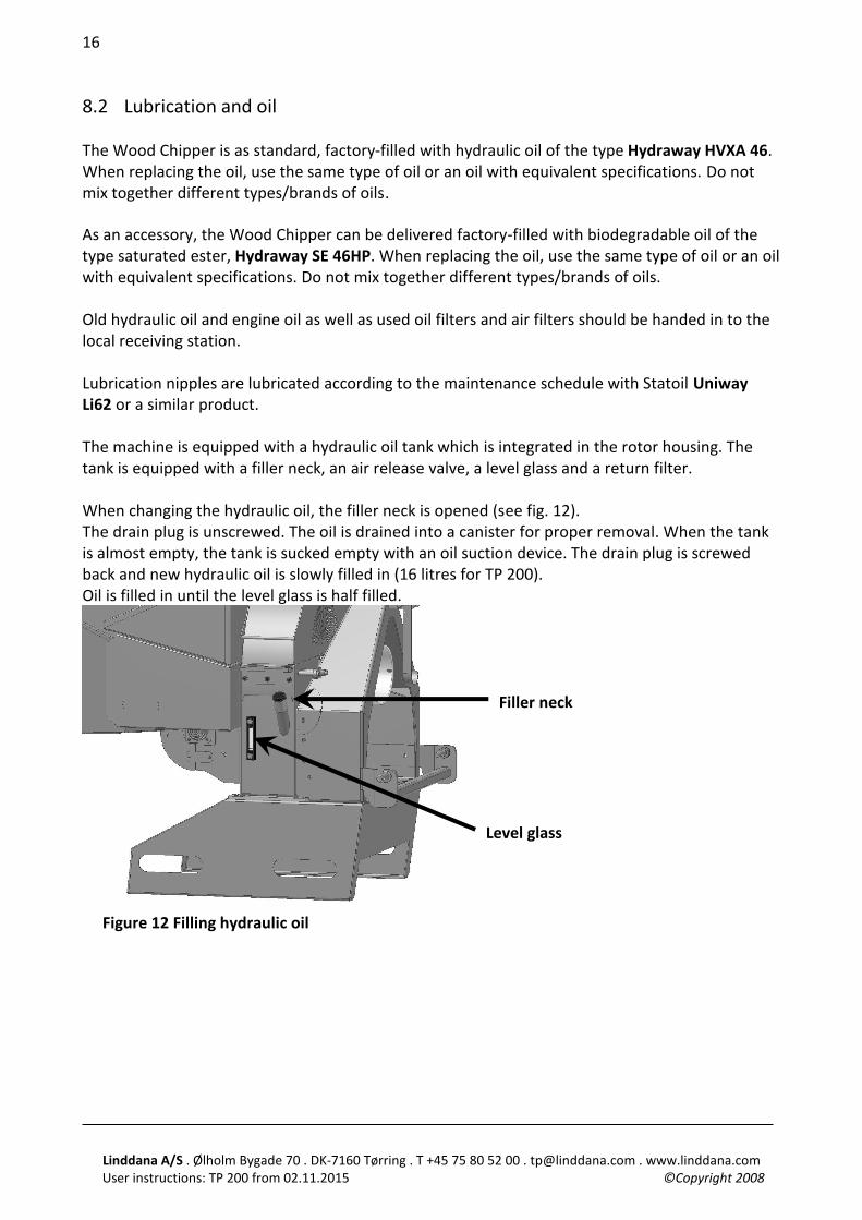
8.2 Lubrication and oil The Wood Chipper is as standard, factory-filled with hydraulic oil of the type Hydraway HVXA 46. When replacing the oil, use the same type of oil or an oil with equivalent specifications. Do not mix together different types/brands of oils. As an accessory, the Wood Chipper can be delivered factory-filled with biodegradable oil of the type saturated ester, Hydraway SE 46HP. When replacing the oil, use the same type of oil or an oil with equivalent specifications. Do not mix together different types/brands of oils. Old hydraulic oil and engine oil as well as used oil filters and air filters should be handed in to the local receiving station. Lubrication nipples are lubricated according to the maintenance schedule with Statoil Uniway Li62 or a similar product. The machine is equipped with a hydraulic oil tank which is integrated in the rotor housing. The tank is equipped with a filler neck, an air release valve, a level glass and a return filter. When changing the hydraulic oil, the filler neck is opened (see fig. 12). The drain plug is unscrewed. The oil is drained into a canister for proper removal. When the tank is almost empty, the tank is sucked empty with an oil suction device. The drain plug is screwed back and new hydraulic oil is slowly filled in (16 litres for TP 200). Oil is filled in until the level glass is half filled.
Filler neck
Level glass
Linddana A/S . Ølholm Bygade 70 . DK-7160 Tørring . T +45 75 80 52 00 . [email protected] . www.linddana.com User instructions: TP 200 from 02.11.2015 ©Copyright 2008
17
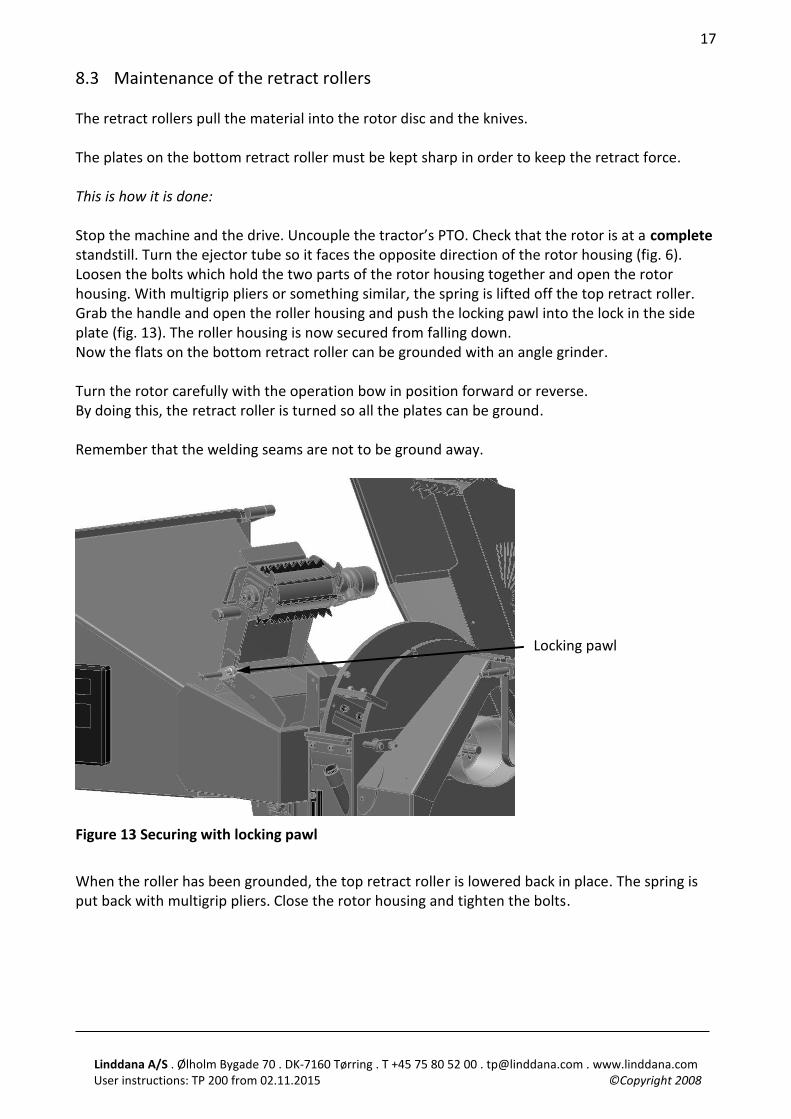
8.3 Maintenance of the retract rollers The retract rollers pull the material into the rotor disc and the knives. The plates on the bottom retract roller must be kept sharp in order to keep the retract force. This is how it is done: Stop the machine and the drive. Uncouple the tractor’s PTO. Check that the rotor is at a complete standstill. Turn the ejector tube so it faces the opposite direction of the rotor housing (fig. 6). Loosen the bolts which hold the two parts of the rotor housing together and open the rotor housing. With multigrip pliers or something similar, the spring is lifted off the top retract roller. Grab the handle and open the roller housing and push the locking pawl into the lock in the side plate (fig. 13). The roller housing is now secured from falling down. Now the flats on the bottom retract roller can be grounded with an angle grinder. Turn the rotor carefully with the operation bow in position forward or reverse. By doing this, the retract roller is turned so all the plates can be ground. Remember that the welding seams are not to be ground away.
Figure 13 Securing with locking pawl
When the roller has been grounded, the top retract roller is lowered back in place. The spring is put back with multigrip pliers. Close the rotor housing and tighten the bolts.
Locking pawl
Linddana A/S . Ølholm Bygade 70 . DK-7160 Tørring . T +45 75 80 52 00 . [email protected] . www.linddana.com User instructions: TP 200 from 02.11.2015 ©Copyright 2008
18
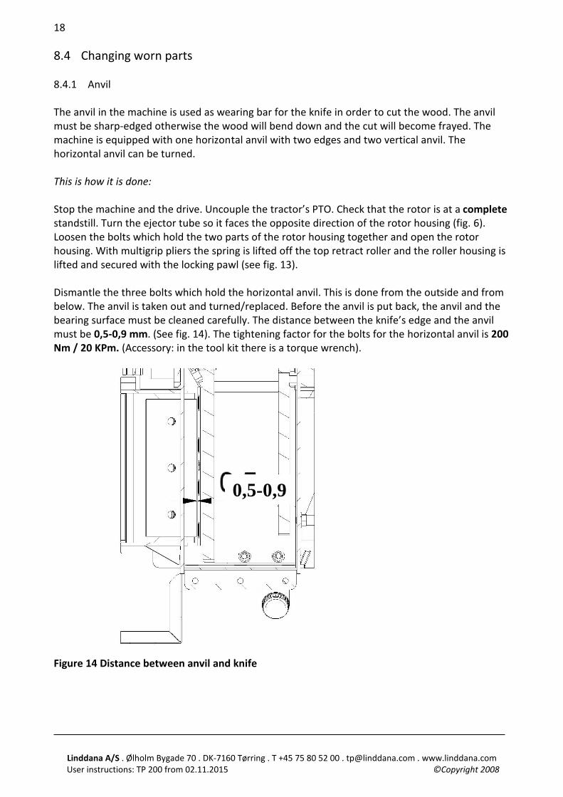
8.4 Changing worn parts 8.4.1 Anvil The anvil in the machine is used as wearing bar for the knife in order to cut the wood. The anvil must be sharp-edged otherwise the wood will bend down and the cut will become frayed. The machine is equipped with one horizontal anvil with two edges and two vertical anvil. The horizontal anvil can be turned. This is how it is done: Stop the machine and the drive. Uncouple the tractor’s PTO. Check that the rotor is at a complete standstill. Turn the ejector tube so it faces the opposite direction of the rotor housing (fig. 6). Loosen the bolts which hold the two parts of the rotor housing together and open the rotor housing. With multigrip pliers the spring is lifted off the top retract roller and the roller housing is lifted and secured with the locking pawl (see fig. 13). Dismantle the three bolts which hold the horizontal anvil. This is done from the outside and from below. The anvil is taken out and turned/replaced. Before the anvil is put back, the anvil and the bearing surface must be cleaned carefully. The distance between the knife’s edge and the anvil must be 0,5-0,9 mm. (See fig. 14). The tightening factor for the bolts for the horizontal anvil is 200 Nm / 20 KPm. (Accessory: in the tool kit there is a torque wrench).
Figure 14 Distance between anvil and knife
0,5-0,9
Linddana A/S . Ølholm Bygade 70 . DK-7160 Tørring . T +45 75 80 52 00 . [email protected] . www.linddana.com User instructions: TP 200 from 02.11.2015 ©Copyright 2008
19
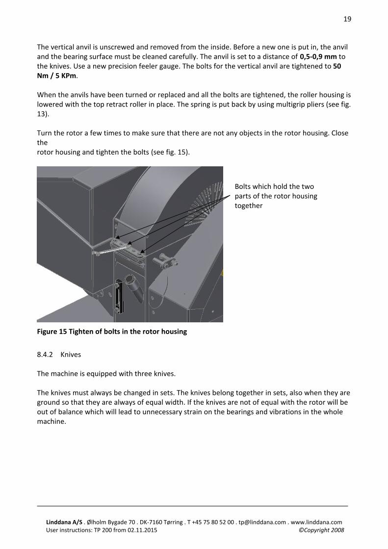
The vertical anvil is unscrewed and removed from the inside. Before a new one is put in, the anvil and the bearing surface must be cleaned carefully. The anvil is set to a distance of 0,5-0,9 mm to the knives. Use a new precision feeler gauge. The bolts for the vertical anvil are tightened to 50 Nm / 5 KPm. When the anvils have been turned or replaced and all the bolts are tightened, the roller housing is lowered with the top retract roller in place. The spring is put back by using multigrip pliers (see fig. 13). Turn the rotor a few times to make sure that there are not any objects in the rotor housing. Close the rotor housing and tighten the bolts (see fig. 15).
Figure 15 Tighten of bolts in the rotor housing
8.4.2 Knives The machine is equipped with three knives. The knives must always be changed in sets. The knives belong together in sets, also when they are ground so that they are always of equal width. If the knives are not of equal with the rotor will be out of balance which will lead to unnecessary strain on the bearings and vibrations in the whole machine.
Bolts which hold the two parts of the rotor housing together
Linddana A/S . Ølholm Bygade 70 . DK-7160 Tørring . T +45 75 80 52 00 . [email protected] . www.linddana.com User instructions: TP 200 from 02.11.2015 ©Copyright 2008
20
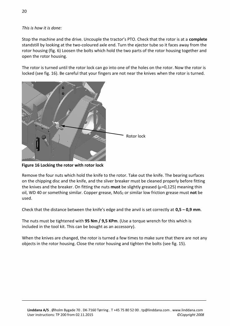
This is how it is done: Stop the machine and the drive. Uncouple the tractor’s PTO. Check that the rotor is at a complete standstill by looking at the two-coloured axle end. Turn the ejector tube so it faces away from the rotor housing (fig. 6) Loosen the bolts which hold the two parts of the rotor housing together and open the rotor housing. The rotor is turned until the rotor lock can go into one of the holes on the rotor. Now the rotor is locked (see fig. 16). Be careful that your fingers are not near the knives when the rotor is turned.
Remove the four nuts which hold the knife to the rotor. Take out the knife. The bearing surfaces on the chipping disc and the knife, and the sliver breaker must be cleaned properly before fitting the knives and the breaker. On fitting the nuts must be slightly greased (µ=0,125) meaning thin oil, WD 40 or something similar. Copper grease, MoS2 or similar low friction grease must not be used. Check that the distance between the knife’s edge and the anvil is set correctly at 0,5 – 0,9 mm. The nuts must be tightened with 95 Nm / 9,5 KPm. (Use a torque wrench for this which is included in the tool kit. This can be bought as an accessory). When the knives are changed, the rotor is turned a few times to make sure that there are not any objects in the rotor housing. Close the rotor housing and tighten the bolts (see fig. 15).
Figure 16 Locking the rotor with rotor lock
Rotor lock
Linddana A/S . Ølholm Bygade 70 . DK-7160 Tørring . T +45 75 80 52 00 . [email protected] . www.linddana.com User instructions: TP 200 from 02.11.2015 ©Copyright 2008
21
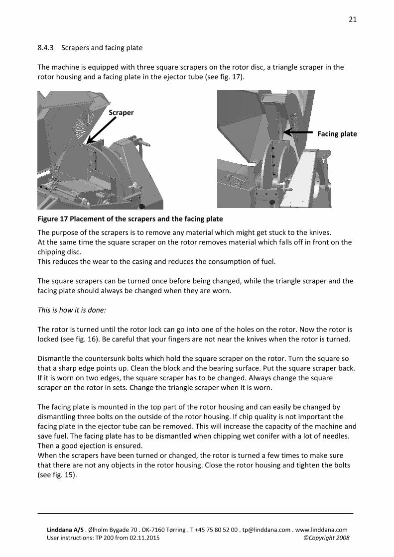
8.4.3 Scrapers and facing plate The machine is equipped with three square scrapers on the rotor disc, a triangle scraper in the rotor housing and a facing plate in the ejector tube (see fig. 17).
Figure 17 Placement of the scrapers and the facing plate
The purpose of the scrapers is to remove any material which might get stuck to the knives. At the same time the square scraper on the rotor removes material which falls off in front on the chipping disc. This reduces the wear to the casing and reduces the consumption of fuel. The square scrapers can be turned once before being changed, while the triangle scraper and the facing plate should always be changed when they are worn. This is how it is done: The rotor is turned until the rotor lock can go into one of the holes on the rotor. Now the rotor is locked (see fig. 16). Be careful that your fingers are not near the knives when the rotor is turned. Dismantle the countersunk bolts which hold the square scraper on the rotor. Turn the square so that a sharp edge points up. Clean the block and the bearing surface. Put the square scraper back. If it is worn on two edges, the square scraper has to be changed. Always change the square scraper on the rotor in sets. Change the triangle scraper when it is worn. The facing plate is mounted in the top part of the rotor housing and can easily be changed by dismantling three bolts on the outside of the rotor housing. If chip quality is not important the facing plate in the ejector tube can be removed. This will increase the capacity of the machine and save fuel. The facing plate has to be dismantled when chipping wet conifer with a lot of needles. Then a good ejection is ensured. When the scrapers have been turned or changed, the rotor is turned a few times to make sure that there are not any objects in the rotor housing. Close the rotor housing and tighten the bolts (see fig. 15).
Scraper
Facing plate
Linddana A/S . Ølholm Bygade 70 . DK-7160 Tørring . T +45 75 80 52 00 . [email protected] . www.linddana.com User instructions: TP 200 from 02.11.2015 ©Copyright 2008
22
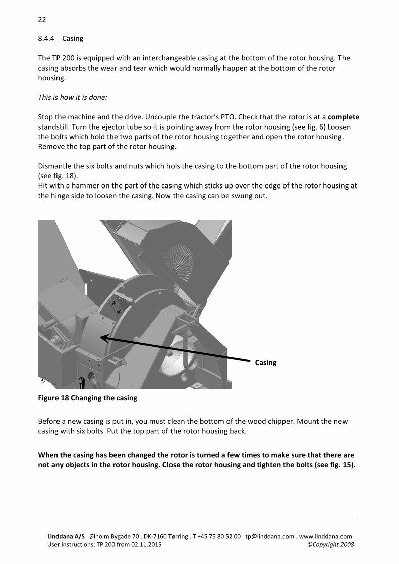
8.4.4 Casing The TP 200 is equipped with an interchangeable casing at the bottom of the rotor housing. The casing absorbs the wear and tear which would normally happen at the bottom of the rotor housing. This is how it is done: Stop the machine and the drive. Uncouple the tractor’s PTO. Check that the rotor is at a complete standstill. Turn the ejector tube so it is pointing away from the rotor housing (see fig. 6) Loosen the bolts which hold the two parts of the rotor housing together and open the rotor housing. Remove the top part of the rotor housing. Dismantle the six bolts and nuts which hols the casing to the bottom part of the rotor housing (see fig. 18). Hit with a hammer on the part of the casing which sticks up over the edge of the rotor housing at the hinge side to loosen the casing. Now the casing can be swung out.
Figure 18 Changing the casing
Before a new casing is put in, you must clean the bottom of the wood chipper. Mount the new casing with six bolts. Put the top part of the rotor housing back.
When the casing has been changed the rotor is turned a few times to make sure that there are not any objects in the rotor housing. Close the rotor housing and tighten the bolts (see fig. 15).
Casing
Linddana A/S . Ølholm Bygade 70 . DK-7160 Tørring . T +45 75 80 52 00 . [email protected] . www.linddana.com User instructions: TP 200 from 02.11.2015 ©Copyright 2008
23
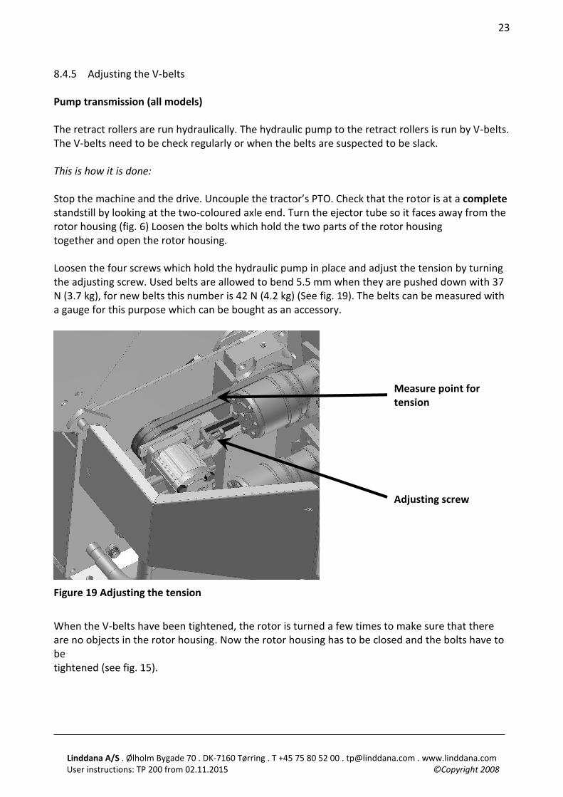
8.4.5 Adjusting the V-belts Pump transmission (all models) The retract rollers are run hydraulically. The hydraulic pump to the retract rollers is run by V-belts. The V-belts need to be check regularly or when the belts are suspected to be slack. This is how it is done: Stop the machine and the drive. Uncouple the tractor’s PTO. Check that the rotor is at a complete standstill by looking at the two-coloured axle end. Turn the ejector tube so it faces away from the rotor housing (fig. 6) Loosen the bolts which hold the two parts of the rotor housing together and open the rotor housing. Loosen the four screws which hold the hydraulic pump in place and adjust the tension by turning the adjusting screw. Used belts are allowed to bend 5.5 mm when they are pushed down with 37 N (3.7 kg), for new belts this number is 42 N (4.2 kg) (See fig. 19). The belts can be measured with a gauge for this purpose which can be bought as an accessory.
Figure 19 Adjusting the tension
When the V-belts have been tightened, the rotor is turned a few times to make sure that there are no objects in the rotor housing. Now the rotor housing has to be closed and the bolts have to be tightened (see fig. 15).
Measure point for tension
Adjusting screw
Linddana A/S . Ølholm Bygade 70 . DK-7160 Tørring . T +45 75 80 52 00 . [email protected] . www.linddana.com User instructions: TP 200 from 02.11.2015 ©Copyright 2008
24
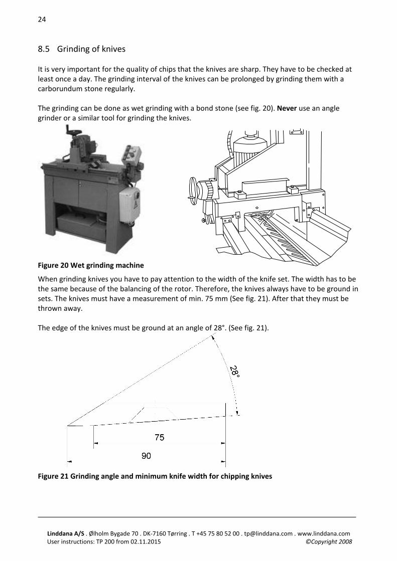
8.5 Grinding of knives It is very important for the quality of chips that the knives are sharp. They have to be checked at least once a day. The grinding interval of the knives can be prolonged by grinding them with a carborundum stone regularly. The grinding can be done as wet grinding with a bond stone (see fig. 20). Never use an angle grinder or a similar tool for grinding the knives.
Figure 20 Wet grinding machine
When grinding knives you have to pay attention to the width of the knife set. The width has to be the same because of the balancing of the rotor. Therefore, the knives always have to be ground in sets. The knives must have a measurement of min. 75 mm (See fig. 21). After that they must be thrown away. The edge of the knives must be ground at an angle of 28°. (See fig. 21).
Figure 21 Grinding angle and minimum knife width for chipping knives
Linddana A/S . Ølholm Bygade 70 . DK-7160 Tørring . T +45 75 80 52 00 . [email protected] . www.linddana.com User instructions: TP 200 from 02.11.2015 ©Copyright 2008
25
9 Special instruction for TP 200 MOBILE The TP 200 MOBILE is a trailer mounted wood chipper comprised of a trailer upon which a wood chipper with own engine is mounted, registered as a trailer tool. The trailer can be coupled to a vehicle with a ball and socket head as a coupling without inspection. When coupling, the seven/thirteen-pole connector and the safety chain must be coupled to the vehicle and the supporting leg must be raised. The hand brake is released before driving. Check that lights, brake lights and turn signal lights work before driving. Measurements of the trailer: Width 1760 mm. Length incl. ball and socket head 3020 mm. Tire assembly: 175/80xR13 Tire pressure: 4,5 bar = 65 psi. TP 200 MOBILE TURNTABLE Tire assembly: 185/60xR13 Tire pressure: 3 bar = 44 psi. In order to avoid destroying the electrical system, the following points must be respected: 1. The ignition key must never be in neutral during operation. 2. The earth connections must be clean. 3. When using a battery charger, the earth cable on the battery must be dismantled. During transport on public roads, the ejector tube has to be turned backwards and secured against rotary motion. This is done by securing the lock for the handle. 10 Special instruction for TP 200 MOBILE TURNTABLE Lubrication of three nipples on the fifth wheel and one nipple on the locking handle for the fifth wheel every 50 hours. During transport the locking bolt on the fifth wheel must be in and the bolt secured with a hairpin cotter. Instruction for wood chipper: See TP 200 PTO Service and guidance for engine: See the enclosed service manual or www.hatz.com
Linddana A/S . Ølholm Bygade 70 . DK-7160 Tørring . T +45 75 80 52 00 . [email protected] . www.linddana.com User instructions: TP 200 from 02.11.2015 ©Copyright 2008
26
Engagement of the wood chipper. At cold starts: Start the engine. Set the throttle so the engine runs smoothly at low revolutions. Let the engine run 30-60 seconds depending on the temperature. Then the wood chipper is engaged slowly and the rpm are increased to working speed “full throttle”. At warm starts: Same approach is followed. Only it is not necessary to let the engine heat up before engaging. The wood chipper must not be engaged at full throttle. When stopping: Let the wood chipper run out of material. Disengage the wood chipper. Let the engine run idle for approximately 30 seconds before the throttle is turned to stop. Turn the ignition key to neutral. (See symbols on the starter box).
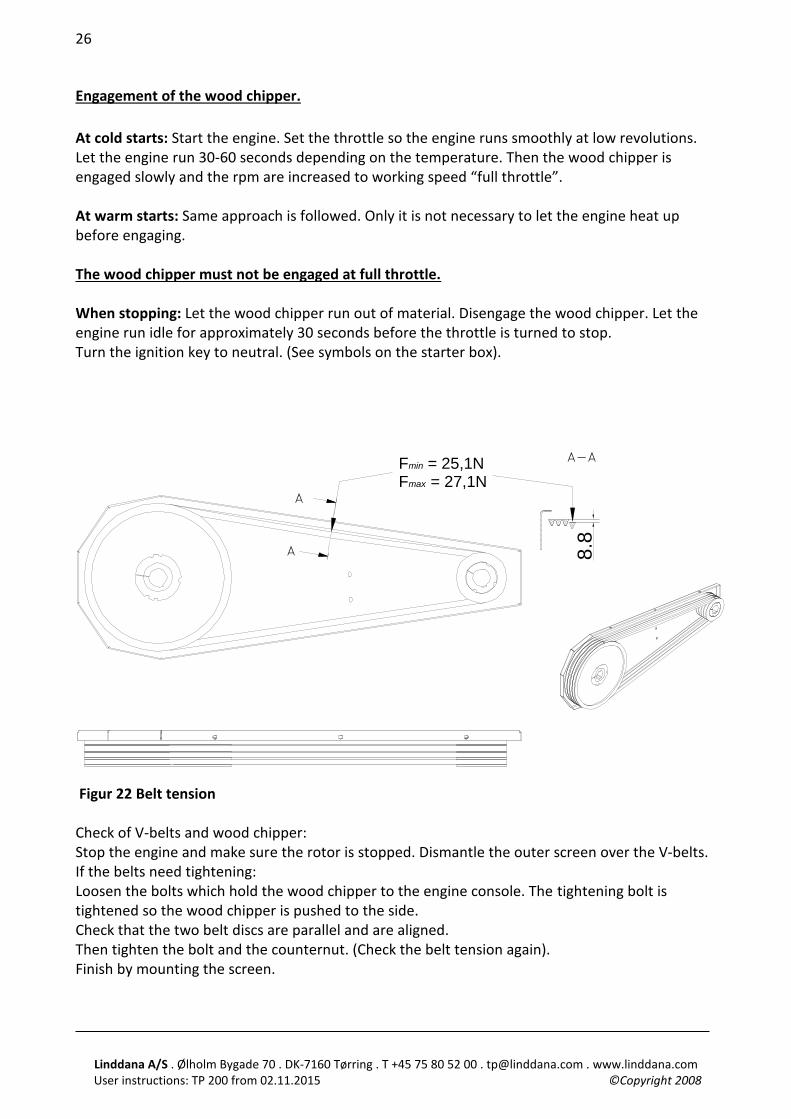
A-A Fmin = 25,1NFmax = 27,1N
8.8
Figur 22 Belt tension Check of V-belts and wood chipper: Stop the engine and make sure the rotor is stopped. Dismantle the outer screen over the V-belts. If the belts need tightening: Loosen the bolts which hold the wood chipper to the engine console. The tightening bolt is tightened so the wood chipper is pushed to the side. Check that the two belt discs are parallel and are aligned. Then tighten the bolt and the counternut. (Check the belt tension again). Finish by mounting the screen.
Linddana A/S . Ølholm Bygade 70 . DK-7160 Tørring . T +45 75 80 52 00 . [email protected] . www.linddana.com User instructions: TP 200 from 02.11.2015 ©Copyright 2008
27
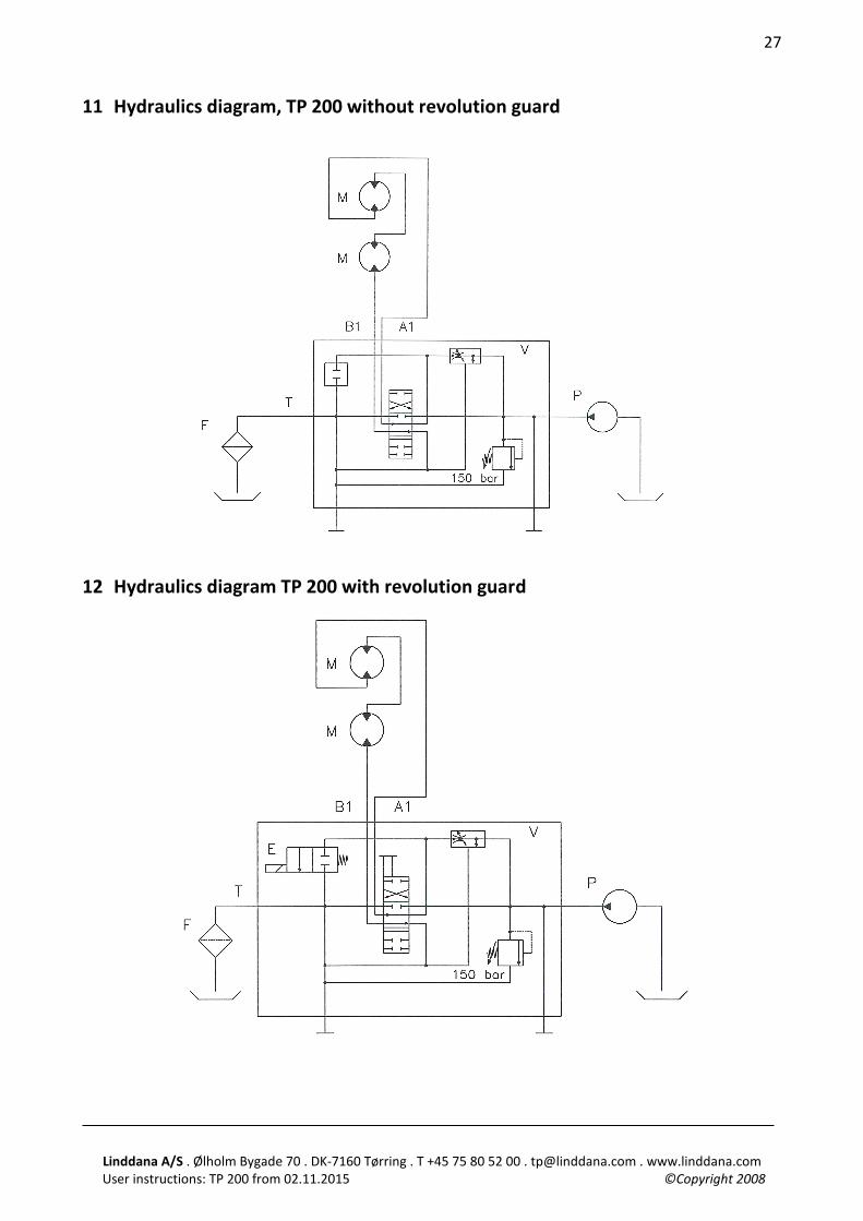
11 Hydraulics diagram, TP 200 without revolution guard
12 Hydraulics diagram TP 200 with revolution guard
Linddana A/S . Ølholm Bygade 70 . DK-7160 Tørring . T +45 75 80 52 00 . [email protected] . www.linddana.com User instructions: TP 200 from 02.11.2015 ©Copyright 2008
28
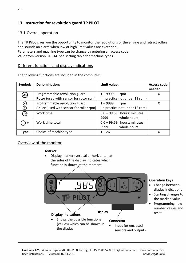
Display
13 Instruction for revolution guard TP PILOT 13.1 Overall operation The TP Pilot gives you the opportunity to monitor the revolutions of the engine and retract rollers and sounds an alarm when low or high limit values are exceeded. Parameters and machine type can be change by entering an access code. Valid from version 816.14. See setting table for machine types. Different functions and display indications The following functions are included in the computer:
Symbol: Denomination: Limit value: Access code
needed
Programmable revolution guard Rotor (used with sensor for rotor rpm)
1 – 9999 rpm (in practice not under 12 rpm)
X
Programmable revolution guard Roller (used with sensor for roller rpm)
1 – 9999 rpm (in practice not under 12 rpm)
X
Work time 0:0 – 99:59 hours: minutes 9999 whole hours
+ Work time total 0:0 – 99:59 hours: minutes 9999 whole hours
Type Choice of machine type 1 – 26 X Overview of the monitor
Type+
Connector • Input for enclosed
sensors and outputs
Display indications • Shows the possible functions
(values) which can be shown in the display
Marker • Display marker (vertical or horizontal) at
the sides of the display indicates which function is shown at the moment
Operation keys • Change between
display indications • Starting changes to
the marked value • Programming new
number values and reset
& 985
Linddana A/S . Ølholm Bygade 70 . DK-7160 Tørring . T +45 75 80 52 00 . [email protected] . www.linddana.com User instructions: TP 200 from 02.11.2015 ©Copyright 2008
29
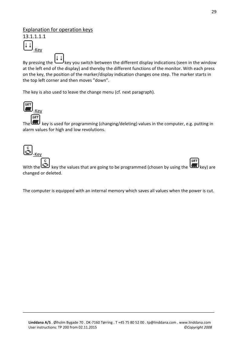
Explanation for operation keys 13.1.1.1.1
-Key
By pressing the key you switch between the different display indications (seen in the window at the left end of the display) and thereby the different functions of the monitor. With each press on the key, the position of the marker/display indication changes one step. The marker starts in the top left corner and then moves ”down”. The key is also used to leave the change menu (cf. next paragraph).
-Key
The key is used for programming (changing/deleting) values in the computer, e.g. putting in alarm values for high and low revolutions.
-Key
With the key the values that are going to be programmed (chosen by using the key) are changed or deleted. The computer is equipped with an internal memory which saves all values when the power is cut.
Linddana A/S . Ølholm Bygade 70 . DK-7160 Tørring . T +45 75 80 52 00 . [email protected] . www.linddana.com User instructions: TP 200 from 02.11.2015 ©Copyright 2008
30
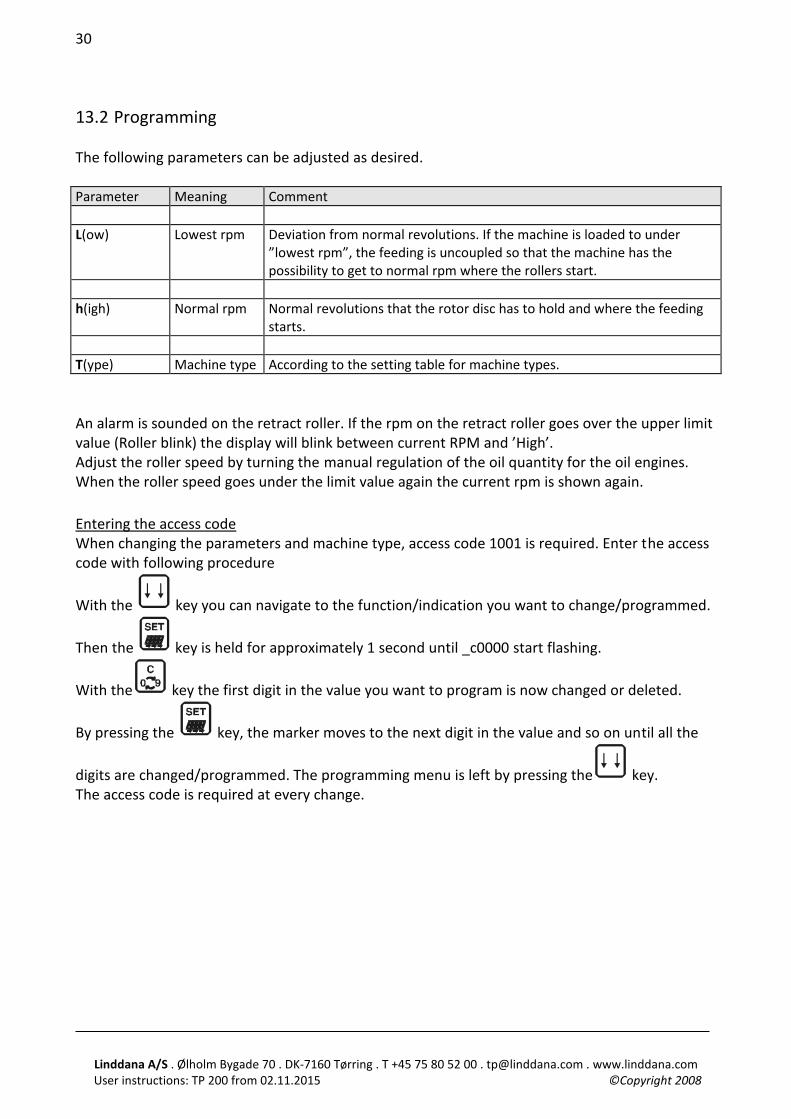
13.2 Programming The following parameters can be adjusted as desired. Parameter Meaning Comment L(ow) Lowest rpm Deviation from normal revolutions. If the machine is loaded to under
”lowest rpm”, the feeding is uncoupled so that the machine has the possibility to get to normal rpm where the rollers start.
h(igh) Normal rpm Normal revolutions that the rotor disc has to hold and where the feeding
starts. T(ype) Machine type According to the setting table for machine types. An alarm is sounded on the retract roller. If the rpm on the retract roller goes over the upper limit value (Roller blink) the display will blink between current RPM and ’High’. Adjust the roller speed by turning the manual regulation of the oil quantity for the oil engines. When the roller speed goes under the limit value again the current rpm is shown again. Entering the access code When changing the parameters and machine type, access code 1001 is required. Enter the access code with following procedure
With the key you can navigate to the function/indication you want to change/programmed.
Then the key is held for approximately 1 second until _c0000 start flashing.
With the key the first digit in the value you want to program is now changed or deleted.
By pressing the key, the marker moves to the next digit in the value and so on until all the
digits are changed/programmed. The programming menu is left by pressing the key. The access code is required at every change.
Linddana A/S . Ølholm Bygade 70 . DK-7160 Tørring . T +45 75 80 52 00 . [email protected] . www.linddana.com User instructions: TP 200 from 02.11.2015 ©Copyright 2008
31
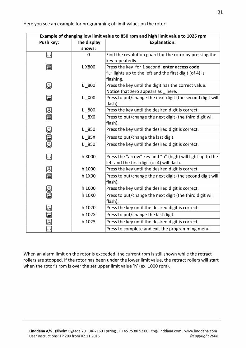
Here you see an example for programming of limit values on the rotor.
Example of changing low limit value to 850 rpm and high limit value to 1025 rpm Push key: The display
shows: Explanation:
0 Find the revolution guard for the rotor by pressing the key repeatedly.
L X800 Press the key for 1 second, enter access code ”L” lights up to the left and the first digit (of 4) is flashing.
L _800 Press the key until the digit has the correct value. Notice that zero appears as _ here.
L _X00 Press to put/change the next digit (the second digit will flash).
L _800 Press the key until the desired digit is correct.
L _8X0 Press to put/change the next digit (the third digit will flash).
L _850 Press the key until the desired digit is correct.
L _85X Press to put/change the last digit.
L _850 Press the key until the desired digit is correct.
h X000 Press the ”arrow” key and ”h” (high) will light up to the left and the first digit (of 4) will flash.
h 1000 Press the key until the desired digit is correct.
h 1X00
Press to put/change the next digit (the second digit will flash).
h 1000 Press the key until the desired digit is correct.
h 10X0 Press to put/change the next digit (the third digit will flash).
h 1020 Press the key until the desired digit is correct.
h 102X Press to put/change the last digit.
h 1025 Press the key until the desired digit is correct.
Press to complete and exit the programming menu. When an alarm limit on the rotor is exceeded, the current rpm is still shown while the retract rollers are stopped. If the rotor has been under the lower limit value, the retract rollers will start when the rotor’s rpm is over the set upper limit value ’h’ (ex. 1000 rpm).
Linddana A/S . Ølholm Bygade 70 . DK-7160 Tørring . T +45 75 80 52 00 . [email protected] . www.linddana.com User instructions: TP 200 from 02.11.2015 ©Copyright 2008
32
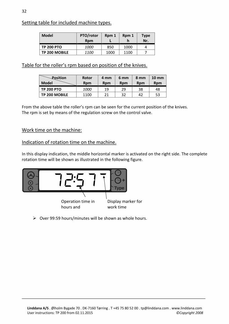
Setting table for included machine types.
Table for the roller’s rpm based on position of the knives.
Position Model
Rotor Rpm
4 mm Rpm
6 mm Rpm
8 mm Rpm
10 mm Rpm
TP 200 PTO 1000 19 29 38 48 TP 200 MOBILE 1100 21 32 42 53
From the above table the roller’s rpm can be seen for the current position of the knives. The rpm is set by means of the regulation screw on the control valve. Work time on the machine: Indication of rotation time on the machine. In this display indication, the middle horizontal marker is activated on the right side. The complete rotation time will be shown as illustrated in the following figure.
Type+
Ø Over 99:59 hours/minutes will be shown as whole hours.
Model PTO/rotor Rpm
Rpm 1 L
Rpm 1 h
Type Nr.
TP 200 PTO 1000 850 1000 4 TP 200 MOBILE 1100 1000 1100 7
72:57! Display marker for work time
Operation time in hours and
Linddana A/S . Ølholm Bygade 70 . DK-7160 Tørring . T +45 75 80 52 00 . [email protected] . www.linddana.com User instructions: TP 200 from 02.11.2015 ©Copyright 2008
33
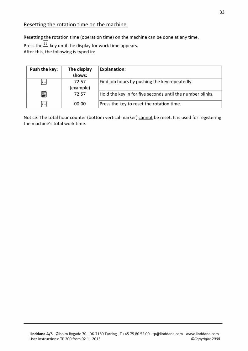
Resetting the rotation time on the machine. Resetting the rotation time (operation time) on the machine can be done at any time.
Press the key until the display for work time appears. After this, the following is typed in:
Push the key: The display shows:
Explanation:
72:57 (example)
Find job hours by pushing the key repeatedly.
72:57 Hold the key in for five seconds until the number blinks.
00:00 Press the key to reset the rotation time. Notice: The total hour counter (bottom vertical marker) cannot be reset. It is used for registering the machine’s total work time.
Linddana A/S . Ølholm Bygade 70 . DK-7160 Tørring . T +45 75 80 52 00 . [email protected] . www.linddana.com User instructions: TP 200 from 02.11.2015 ©Copyright 2008
34
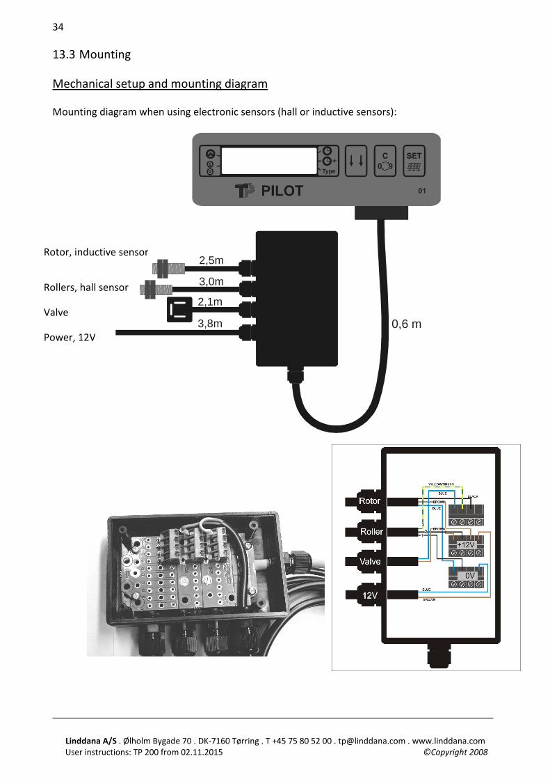
13.3 Mounting Mechanical setup and mounting diagram Mounting diagram when using electronic sensors (hall or inductive sensors):
0,6 m
2,5m
3,0m
3,8m
2,1m
Type+
Rotor, inductive sensor
Rollers, hall sensor
Valve
Power, 12V
Linddana A/S . Ølholm Bygade 70 . DK-7160 Tørring . T +45 75 80 52 00 . [email protected] . www.linddana.com User instructions: TP 200 from 02.11.2015 ©Copyright 2008
35
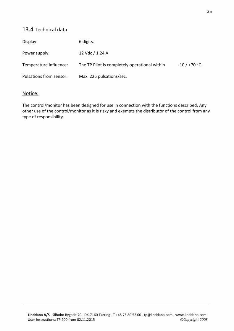
13.4 Technical data Display: 6 digits. Power supply: 12 Vdc / 1,24 A Temperature influence: The TP Pilot is completely operational within -10 / +70 °C. Pulsations from sensor: Max. 225 pulsations/sec. Notice:
The control/monitor has been designed for use in connection with the functions described. Any other use of the control/monitor as it is risky and exempts the distributor of the control from any type of responsibility.
Linddana A/S . Ølholm Bygade 70 . DK-7160 Tørring . T +45 75 80 52 00 . [email protected] . www.linddana.com User instructions: TP 200 from 02.11.2015 ©Copyright 2008
36
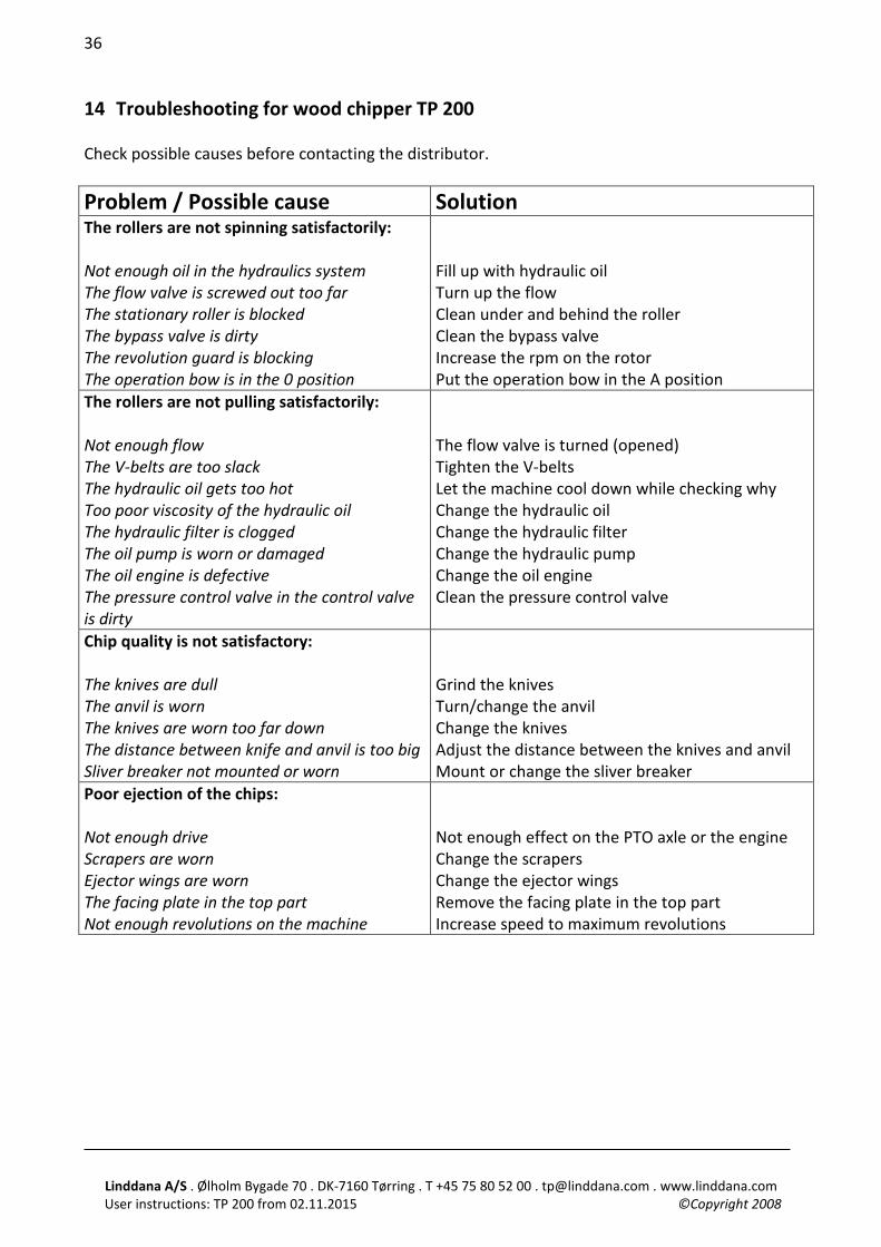
14 Troubleshooting for wood chipper TP 200 Check possible causes before contacting the distributor. Problem / Possible cause Solution The rollers are not spinning satisfactorily: Not enough oil in the hydraulics system The flow valve is screwed out too far The stationary roller is blocked The bypass valve is dirty The revolution guard is blocking The operation bow is in the 0 position
Fill up with hydraulic oil Turn up the flow Clean under and behind the roller Clean the bypass valve Increase the rpm on the rotor Put the operation bow in the A position
The rollers are not pulling satisfactorily: Not enough flow The V-belts are too slack The hydraulic oil gets too hot Too poor viscosity of the hydraulic oil The hydraulic filter is clogged The oil pump is worn or damaged The oil engine is defective The pressure control valve in the control valve is dirty
The flow valve is turned (opened) Tighten the V-belts Let the machine cool down while checking why Change the hydraulic oil Change the hydraulic filter Change the hydraulic pump Change the oil engine Clean the pressure control valve
Chip quality is not satisfactory: The knives are dull The anvil is worn The knives are worn too far down The distance between knife and anvil is too big Sliver breaker not mounted or worn
Grind the knives Turn/change the anvil Change the knives Adjust the distance between the knives and anvil Mount or change the sliver breaker
Poor ejection of the chips: Not enough drive Scrapers are worn Ejector wings are worn The facing plate in the top part Not enough revolutions on the machine
Not enough effect on the PTO axle or the engine Change the scrapers Change the ejector wings Remove the facing plate in the top part Increase speed to maximum revolutions
Linddana A/S . Ølholm Bygade 70 . DK-7160 Tørring . T +45 75 80 52 00 . [email protected] . www.linddana.com User instructions: TP 200 from 02.11.2015 ©Copyright 2008
37
15 Warranty obligation for wood chipper The warranty is valid 12 months from date of purchase to rectify defects that irrevocably are due to defects in materials or workmanship. The warranty covers faulty components which are repaired or replaced. Transportation costs and wages for changes are the responsibility of the customer. Upon any claims, the changed parts must be sent to Linddana for investigation. Linddana alone decides whether the claim can be approved. The following is an excerpt from Linddana’s Terms of Sales and Delivery (item 4 and 5). Claims Any and all risk concerning the goods is passed to the buyer at the time of delivery of the goods. A claim concerning the goods has to be done in writing to Linddana as quickly as possible, and no later than 8 days after delivery. If Linddana has not received the claim before the deadline stated, the objections to quantity and quality that the buyer might have will lapse. Linddana is entitled and obligated to correct any and all faults which are caused by the construction, material or manufacture. Linddana alone determines whether the remedy is to be done with repairs or changes of the defective parts. In case of repairs, the buyer is obligated to deliver and collect the goods sold in the workshop determined by Linddana at no expense to Linddana. In case of changing the defective parts, the buyer is obligated to send in the defective parts to Linddana at no expense to Linddana. Linddana is entitled to changing the defective goods. Linddana’s responsibility only covers faults which occur within a year of the goods sold being delivered. Linddana has no liability besides those stated in the present item. This includes any loss the fault might cause including loss of work, loss of earnings and other economical implication losses. Warranty conditions If Linddana has decided to grant a warranty, then this has faults in the construction, material or manufacture. A warranty granted by Linddana does not cover faults which occur as a result of imperfect maintenance, incorrect mounting, changes made by the buyer or wrong use of the good. The warranty furthermore does not cover normal wear and tear or deterioration. Linddana’s warranty obligation presupposes that the buyer documents that a stated fault is not due to the conditions which are exempt from the warranty cf. afore-mentioned. The buyer must let Linddana know in writing about any faults to the goods sold no later than 8 days after the fault should have been realized by the buyer. If the buyer does not let Linddana
Linddana A/S . Ølholm Bygade 70 . DK-7160 Tørring . T +45 75 80 52 00 . [email protected] . www.linddana.com User instructions: TP 200 from 02.11.2015 ©Copyright 2008
38
know before the expiration of this deadline and before the warranty period runs out, the buyer looses the right to make any claims concerning the fault. Linddana is entitled and obligated to remedy any faults which are covered by a warranty granted by Linddana. Linddana alone decides if the remedy is to be done as repairs or changes of the defective parts, everything under the terms stipulated in item 4. Linddana has no other liability for those faults. This includes any loss the fault might cause including loss of work, loss of earnings and other economical implication losses. The warranty does not cover:
• If a defect with just cause can be attributed to inappropriate use. • Use of unoriginal spare parts, including worn parts. • Wrong adjustment or use of the machine. • Use of wrong lubricant or hydraulic oil. • Wear on cross at PTO axle. • Tightening spring for rollers. • V-belts. • Knives and anvil which break because of foreign bodies in the machine.
Linddana A/S . Ølholm Bygade 70 . DK-7160 Tørring . T +45 75 80 52 00 . [email protected] . www.linddana.com User instructions: TP 200 from 02.11.2015 ©Copyright 2008
39
16 Technical data wood chipper
Type TP 200 PTO TP 200 MOBILE TP 200 MOBILE TURNTABLE
Chipping principle Disc chipper Disc chipper Disc chipper Rotor disc diameter, mm 760 760 760 Number of revolutions PTO rpm* 1000
(540 With speed-up gear) 1000 1000
Knives, pieces 3 3 3 Effect need min/max kW/(HP) 30-85/(40-115) 39/(52) 39/(52) Max. Wood diameter, mm 200 200 200 Chip length, mm 10 10 10 Weight, kg 700 1350 1550 Height, mm 2440 2607 2741 Width, mm 1415 1760 1760 Length, mm 2480 3017 3017 PTO transmission axle: Walterscheid type 2400 with free running. Rights to changes in the construction and specifications without previous notice reserved.
Linddana A/S . Ølholm Bygade 70 . DK-7160 Tørring . T +45 75 80 52 00 . [email protected] . www.linddana.com User instructions: TP 200 from 02.11.2015 ©Copyright 2008
40
Figure 23 Dimensional sketch TP 200 PTO
Figure 24 Dimensional sketch TP 200 MOBILE
Figure 25 Dimensional sketch TP 200 MOBILE TURNTABLE
Linddana A/S . Ølholm Bygade 70 . DK-7160 Tørring . T +45 75 80 52 00 . [email protected] . www.linddana.com User instructions: TP 200 from 02.11.2015 ©Copyright 2008
41
17 Accessories
• Tool kit incl. torque wrench. • Prolonged ejector tube horizontal. • Extension for ejector tube vertical. • Lock for ball and socket coupling (TP 200 MOBILE). • Light boom (TP 200 PTO).
18 Spare parts catalogue
Related Documents