1 User Manual (DSP5.1 For MPC6515) V1.2

Welcome message from author
This document is posted to help you gain knowledge. Please leave a comment to let me know what you think about it! Share it to your friends and learn new things together.
Transcript

1
User Manual (DSP5.1 For MPC6515)
V1.2

2
Chapter 1 Installation of the system
1.1 Contents of the system ―――――――――――――――――――――――4
1.2 Requirement of PC ―――――――――――――――――――――――――4
1.3 Installation of MPC6515 card ―――――――――――――――――――――4
1.4 Installation of the software ―――――――――――――――――――――――4
Chapter 2 Explanation for CorelDraw edition
2.1 Laser output ―――――――――――――――――――――――――――――6
2.2 Import DST file ―――――――――――――――――――――――――――10
2.3 Output file ―――――――――――――――――――――――――――――10
2.4 Options ―――――――――――――――――――――――――――――――10
Chapter 3 Explanation for AutoCAD edition
3.1 Laser output ―――――――――――――――――――――――――――――11
3.2 Export data ―――――――――――――――――――――――――――――11
3.3 Options ―――――――――――――――――――――――――――――――11
3.4 Unite line ―――――――――――――――――――――――――――――11
Chapter 4 Explanation for universal edition
4.1 File ―――――――――――――――――――――――――――――――――12
4.2 Edit ―――――――――――――――――――――――――――――――――13
4.3 Draw ―――――――――――――――――――――――――――――――15
4.4 Tools ―――――――――――――――――――――――――――――――18
4.5 Laser ―――――――――――――――――――――――――――――――20
4.6 View ―――――――――――――――――――――――――――――――24
4.7 Help ―――――――――――――――――――――――――――――――24
4.8 Other button on the tool bar ―――――――――――――――――――――25
Chapter 5 Laser output
5.1 Layer ―――――――――――――――――――――――――――――――26
5.2 Test ―――――――――――――――――――――――――――――――――31
5.3 Auxiliary processing parameters ―――――――――――――――――――32
5.4 Download data (Stand Alone) ―――――――――――――――――――――33
Chapter 6 Options
6.1 Main interface ―――――――――――――――――――――――――――35
6.2 Worktable ―――――――――――――――――――――――――――――36
6.3 Feeding ―――――――――――――――――――――――――――――――37
6.4 Cut ―――――――――――――――――――――――――――――――――38
6.5 Engrave ―――――――――――――――――――――――――――――――40
6.6 Grade engrave ―――――――――――――――――――――――――――41
6.7 Hole ―――――――――――――――――――――――――――――――42
Chapter 7 PAD03 operation

3
7.1 Main interface of PAD03 ―――――――――――――――――――――――43
7.2 Processing interface of PAD03 ―――――――――――――――――――――44
7.3 Accessory interface of PAD03 ―――――――――――――――――――――44
Chapter 8 Text display operation
8.1 Main interface ―――――――――――――――――――――――――――46
8.2 Jog set interface ―――――――――――――――――――――――――――47
8.3 Laser set interface ―――――――――――――――――――――――――47
8.4 Work interface ―――――――――――――――――――――――――――47
Chapter 9 Download Files
9.1 Update MPC6515 ―――――――――――――――――――――――――――48
9.2 Download processing file (*.mol) ―――――――――――――――――――48
Chapter 10 Comments on tool programs
10.1 Version check program ―――――――――――――――――――――――50
Chapter 11 Addenda
11.1 How to make AI (Adobe Illustrator) files ―――――――――――――――――51
11.2 FAQ―――――――――――――――――――――――――――――――――51

4
Chapter 1 Installation of the system
1.1 Contents of the system
The system is made up of hardware (control card) and software. Hardware includes
a MPC6515 control card and PAD03 (or POP Text Display). And software includes
drivers for the control card and control software. The whole control system is contained
in a packing carton and software in a CD.
Descriptions on software directories:
Subdirectory Files Explanations
Install Files of installation
Drivers Drivers of control card
Demo Data PLT, BMP etc. demo data
Read me Explanations of the software edition
1.2 Requirement of PC
Requirement of OS: Window2000、Win XP
IBM compatible computer
CPU: Above Pentium 2
Storage: 128 Meg
HD: Above 10 G
CD-ROM
Above 2 USB interfaces
1.3 Installation of MPC6515 card
Run the file Drivers\SetupMpc6515Drv.exe.
If this program is not installed, PC can’t communicate with MPC6515.
1.4 Installation of the software
Run Setup.exe and the dialog box as following:

5
There are three options in “Edition type”. The default path is “C:\LaserCut50”. Click
and you can change the install path. Click “Setup” and the software will be
installed.

6
Chapter 2 Explanation for CorelDraw Edition
Run CorelDraw and the interface as following.
2.1 Laser output
Click this button, the dialog box is as following.
2.1.1 Layer
Please refer to “Chapter 5”
2.1.2 Test
Laser output Import DST file Export file Options
7
Please refer to “Chapter 5”
2.1.3 Stand alone
Please refer to “Chapter 5”
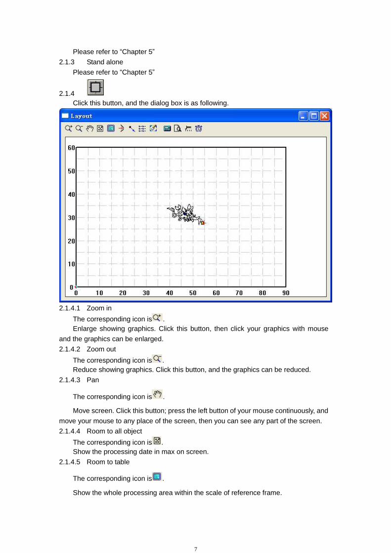
2.1.4
Click this button, and the dialog box is as following.
2.1.4.1 Zoom in
The corresponding icon is .
Enlarge showing graphics. Click this button, then click your graphics with mouse
and the graphics can be enlarged.
2.1.4.2 Zoom out
The corresponding icon is .
Reduce showing graphics. Click this button, and the graphics can be reduced.
2.1.4.3 Pan
The corresponding icon is .
Move screen. Click this button; press the left button of your mouse continuously, and
move your mouse to any place of the screen, then you can see any part of the screen.
2.1.4.4 Room to all object
The corresponding icon is .
Show the processing date in max on screen.
2.1.4.5 Room to table
The corresponding icon is .
Show the whole processing area within the scale of reference frame.
8
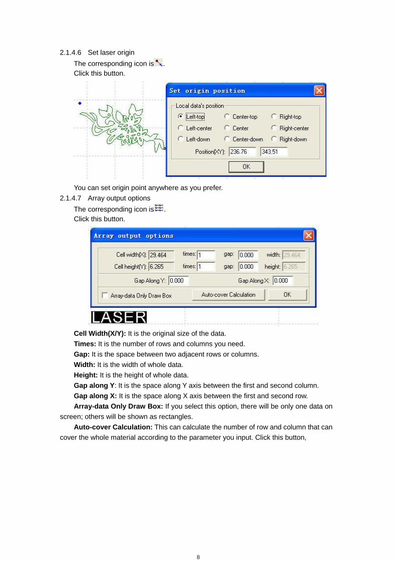
2.1.4.6 Set laser origin
The corresponding icon is .
Click this button.
You can set origin point anywhere as you prefer.
2.1.4.7 Array output options
The corresponding icon is .
Click this button.
Cell Width(X/Y): It is the original size of the data.
Times: It is the number of rows and columns you need.
Gap: It is the space between two adjacent rows or columns.
Width: It is the width of whole data.
Height: It is the height of whole data.
Gap along Y: It is the space along Y axis between the first and second column.
Gap along X: It is the space along X axis between the first and second row.
Array-data Only Draw Box: If you select this option, there will be only one data on
screen; others will be shown as rectangles.
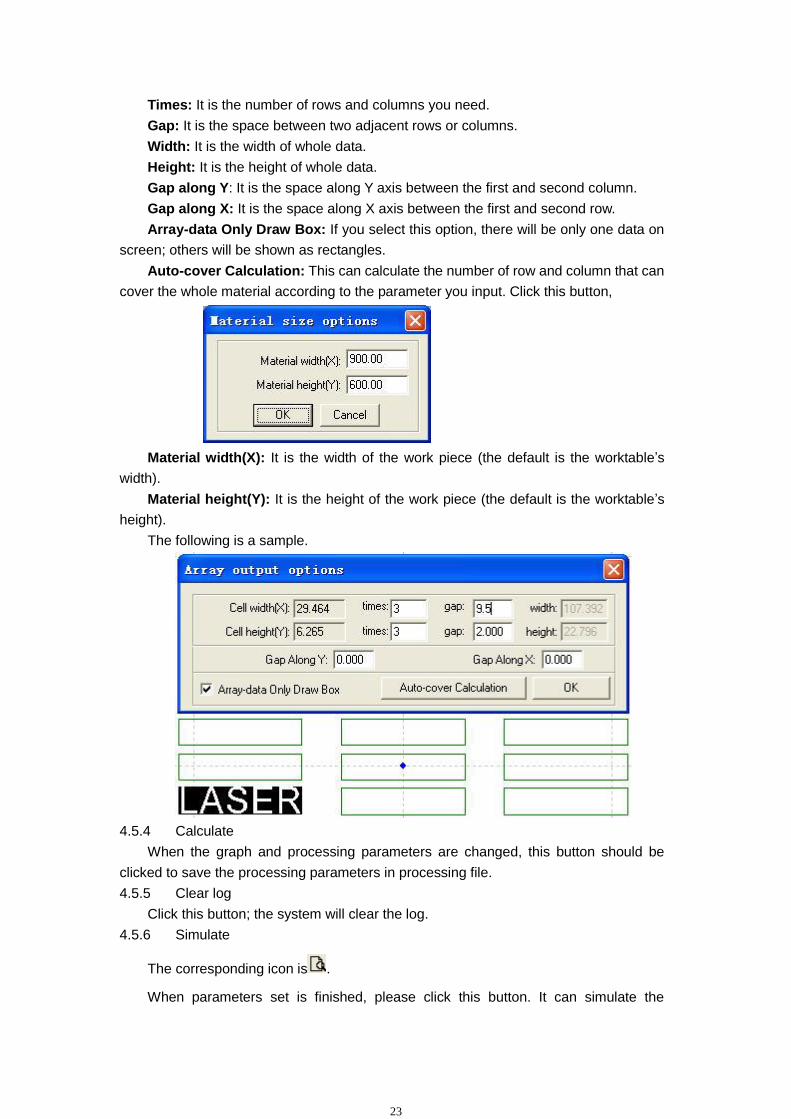
Auto-cover Calculation: This can calculate the number of row and column that can
cover the whole material according to the parameter you input. Click this button,

9
Material width(X): It is the width of the work piece (the default is the worktable’s
width).
Material height(Y): It is the height of the work piece (the default is the worktable’s
height).
The following is a sample.
2.1.4.8 Move working table
The corresponding icon is .
Click this button and move mouse, and you can change the position that the data is
in the working table.
2.1.4.9 Calculate
The corresponding icon is .
When the graph and processing parameters are changed, this button should be
clicked to save the processing parameters in processing file.
2.1.4.10 Simulate
The corresponding icon is .
When parameters set is finished, please click this button. It can simulate the
procedure of output for checking the result of output.
2.1.4.11 Set simulate speed
The corresponding icon is .

10
Click this button.
By this tool, you can adjust the simulate speed.
2.1.4.12 Estimate work time
The corresponding icon is .
Click this button, it will show the work time.
2.1.5
Calculate. When the graph and processing parameters are changed, this button
should be clicked to save the processing parameters in processing file.
2.2 Import DST file
Click this button, you can import DST files.
2.3 Output file
Click this button; you can export the processing files.
2.4 Options
Please refer to “Chapter 6”
11
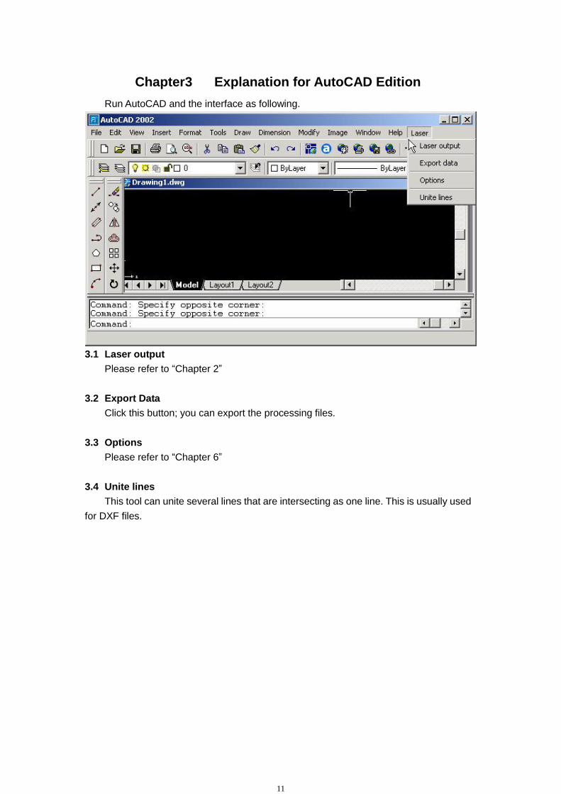
Chapter3 Explanation for AutoCAD Edition
Run AutoCAD and the interface as following.
3.1 Laser output
Please refer to “Chapter 2”
3.2 Export Data
Click this button; you can export the processing files.
3.3 Options
Please refer to “Chapter 6”
3.4 Unite lines
This tool can unite several lines that are intersecting as one line. This is usually used
for DXF files.

12
Chapter 4 Explanation for Universal Edition
When run the software, the interface is as following. All system function can be
found on tool bars.
Let mouse stay on an icon for a moment, and it will show the explanation of basic
function of tools bar. The following is the explanation of all tool bars.
4.1 File
4. 1.1 New
The corresponding icon is .
Create a new file.
4.1.2 Open
The corresponding icon is .
Load process data made by the software. The file format is ECP-EC Project File
(﹡.ecp).
4.1.3 Save
The corresponding icon is .
Save the graphics data that is defined processing parameters as ECP-EC Project
Set array work
Import data
Simulation Save data
Set origin position
Edit tools bar Layer tools bar Status bar

13
File (﹡.ecp).
4.1.4 Save As
Save a ECP-EC Project File (﹡.ecp) as another ECP-EC Project File (﹡.ecp).
4.1.5 Import
The corresponding icon is .
Load data that the software supports. The software can support﹡.PLT、﹡.AI、
﹡.DXF、﹡.DST、﹡.BMP etc files.
4.1.6 Export
Save the vector graphics data that is in current window as a standard PLT file (*.PLT)
or DXF file.
4.1.7 Relink machine
When the PC failed to link with MPC6515 control card, click this button and relink
PC with the control card.
4.1.8 Options
Click this button, and the interface is as following.
Any change of these parameters will change the performance of the machine.
Before changing the parameter, you should consult the supplier.
Details please refer to “Chapter 6”
4.1.9 Exit
Click this button, and the software will close.
4.2 Edit
4.2.1 Undo
The corresponding icon is .
4.2.2 Redo
The corresponding icon is .

14
4.2.3 Refresh
The corresponding icon is .
Click this button, and you can refresh the screen.
4.2.4 Pick
The corresponding icon is .
Select graphics. Select graphics or a part of the graphics. You can delete, move,
change layers of the graphics you select.
There are other functions about this button.
Click this button, and select the graphics.
Move the mouse to the nodes, then drag the mouse, you can change the shape of
the graphics as you prefer.
After you select the graphics, click “Spacebar”.
Input the coordinate of the X-axis and Y-axis, you can change the position of the
graphics.
4.2.5 Zoom in
The corresponding icon is .
Enlarge showing graphics. Click this button, then click your graphics with mouse
and the graphics can be enlarged.
4.2.6 Zoom out
The corresponding icon is .
Reduce showing graphics. Click this button, and the graphics can be reduced.
4.2.7 Pan
The corresponding icon is .
15
Move screen. Click this button; press the left button of your mouse continuously, and
move your mouse to any place of the screen, then you can see any part of the screen.
4.2.8 Room to table
The corresponding icon is .
Show the whole processing area within the scale of reference frame.
4.2.9 Room to all object
The corresponding icon is .
Show the processing date in max on screen.
4.2.10 Center to table
When the data is input, it may be out of the reference frame. Click this button and
you can move data to reference frame. If you select a graphics and click this button, the
selected graphics will be moved to the center of the reference frame.
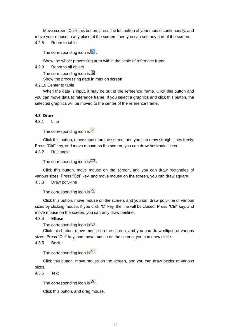
4.3 Draw
4.3.1 Line
The corresponding icon is .
Click this button, move mouse on the screen, and you can draw straight lines freely.
Press “Ctrl” key, and move mouse on the screen, you can draw horizontal lines.
4.3.2 Rectangle
The corresponding icon is .
Click this button, move mouse on the screen, and you can draw rectangles of
various sizes. Press “Ctrl” key, and move mouse on the screen, you can draw square.
4.3.3 Draw poly-line
The corresponding icon is .
Click this button, move mouse on the screen, and you can draw poly-line of various
sizes by clicking mouse. If you click “C” key, the line will be closed. Press “Ctrl” key, and
move mouse on the screen, you can only draw beeline.
4.3.4 Ellipse
The corresponding icon is .
Click this button, move mouse on the screen, and you can draw ellipse of various
sizes. Press “Ctrl” key, and move mouse on the screen, you can draw circle.
4.3.5 Bezier
The corresponding icon is .
Click this button, move mouse on the screen, and you can draw bezier of various
sizes.
4.3.6 Text
The corresponding icon is .
Click this button, and drag mouse.

16
If you want to edit the text, please click this button and drag mouse on the text.
Before you change the size of the text, the text should be changed to curve. The “To
curve” button is located in “Tools-- To curve”. When the text changed to curve, the
content of the text can’t be changed.
4.3.7 Copies
The corresponding icon is .
Click “select” button , and choose the graphics you want to array copy. Then click
this button.
Input relative parameters, then a number of graphics are copied as “rows X
columns”.
Gap means the distance between two adjacent rows or columns.
4.3.8 Rotate
The corresponding icon is .
Click “pick” button , and choose the graphics you want to rotate. Then click this
button, you can rotate the graphics. Click “Spacebar” key after you click , you will see
following dialog box.

17
Input the number you want, and you can control the rotate angle.
4.3.9 Mirror (vertically)
The corresponding icon is .
Click “pick” button , and choose the graphics you want to edit. Then click this
button, you can change the shape of the graphics. The following is a sample. The upper
is original graphics, and the other is edited.
4.3.10 Mirror (horizontally)
The corresponding icon is .
Click “pick” button , and choose the graphics you want to edit. Then click this
button, you can change the shape of the graphics. The following is a sample. The upper
is original graphics, and the other is edited.
4.3.11 Size
The corresponding icon is .
Change the size of graphics. Click “pick” button , then select the graphics you
want to edit. Click this button.

18
Now, input the number you prefer on X and Y-axis. Click “OK”, the size of graphics
can be changed. If you don’t want to change the proportion of X and Y-axis, you can
input one of the number (X or Y), then click the button .
4.3.12 Align
The corresponding icon is .
There are 7 options for aligning.
4.3.13 Edit node
The corresponding icon is .
Edit the nodes of the selected vector graphics. Click this button, the nodes of the
selected graphics will show as small squares.
Move mouse to the node, and you can change the shape of the graph by dragging
mouse.
Move mouse to the graphics, the mouse will change to a crisscross. Dblclicking
mouse will add a node. Move mouse to the node and click “Delete” key, the node will be
deleted.
4.4 Tools
4.4.1 Data check
Click this button.

19
This can check if the data is closed, overlap or self-intersect.
Tol: overlap error of dots.
When the data is input two times or more, it can’t be processed properly. So if you
find something is unusual such as you can’t engrave a graphics data, please use this tool
to check overlap or others. Click “Check” and it will inform which part of the data is in
trouble by red it. Then click “Delete” key and you can delete unwanted data. Before you
click “Delete” key, you have to click .
4.4.2 Smooth curve
The corresponding icon is .
This tool can smooth curves. This can improve the cutting speed. Select the
graphics you want, and click this button.
There are 3 options. Compared with “One Level” and “Two Level”, “Three Level” is
smoother. But the distortion is bigger than the others.
4.4.3 Unite line
This tool can unite several lines that are intersecting as one line. This is usually used
for DXF files.
4.4.4 Offset curve
The corresponding icon is .
This tool can expand or reduce the data. Select the data you need and click this
button.
Input parameters you need you will get a parallel data and the new data will be set
as another layer. The following is a sample.
4.4.5 To curve

20
Convert the text to curve.
4.4.6 Output order
By this tool, you can layout the processing sequence as you prefer. Click this button,
Each ID number represents a separate graphics. Change the sequence of the ID
number, and the processing sequence will be changed.
4.4.7 Invert colors
The corresponding icon is .
This is only for BMP. Click “pick” button , and choose the graphics you want to
edit. Then click this button, the black part will be changed to white and white to black.
The following is the sample.
4.5 Laser
4.5.1 Define cut route
The corresponding icon is .
This software will define the starting point and direction automatically. Generally, the
point is on the corner. When you need to change the starting point and direction, you can
click this button, and then move mouse to the graphics. The mouse will change to be a
crisscross. Now click the left key of mouse on any point of the graphics, and this point will
be the new starting point. You can change the direction by clicking “F” key. The following
is a sample.

21
Click “Spacebar” and you can set lead in/out line.
Calculate: select this option and you can set lead in/out lines.
Entry/Exit type: type of lead in/out lines. There are 2 types: arc and line.
Arc radius: radius of lead in/out arc.
Line length: length of lead in/out lines.
Line angle: angle of lead in/out lines.
: set the exit parameters as same as that of entry.
Auto set direction: this software will set where the lead in /out lines are (in or out of
the graphics outline) automatically.
Manual set direction: set where the lead in /out lines are.
Over lap/leave space: this option determines whether the processing effect is closed.
The length of over lap (or leave space) is set by the input number beside this option.

22
4.5.2 Set laser origin
The corresponding icon is .
Click this button.
You can set origin point anywhere as you prefer.
4.5.3 Array output options
The corresponding icon is .
Click this button.
Cell Width(X/Y): It is the original size of the data.
23
Times: It is the number of rows and columns you need.
Gap: It is the space between two adjacent rows or columns.
Width: It is the width of whole data.
Height: It is the height of whole data.
Gap along Y: It is the space along Y axis between the first and second column.
Gap along X: It is the space along X axis between the first and second row.
Array-data Only Draw Box: If you select this option, there will be only one data on
screen; others will be shown as rectangles.
Auto-cover Calculation: This can calculate the number of row and column that can
cover the whole material according to the parameter you input. Click this button,
Material width(X): It is the width of the work piece (the default is the worktable’s
width).
Material height(Y): It is the height of the work piece (the default is the worktable’s
height).
The following is a sample.
4.5.4 Calculate
When the graph and processing parameters are changed, this button should be
clicked to save the processing parameters in processing file.
4.5.5 Clear log
Click this button; the system will clear the log.
4.5.6 Simulate
The corresponding icon is .
When parameters set is finished, please click this button. It can simulate the

24
procedure of output for checking the result of output.
Click “Esc” on the keyboard and you can cancel the simulation process.
4.6 View
4.6.1 Toolbar
File toolbar: Click this button, you can display or hide the following bar.
Output toolbar: Click this button, you can display or hide the following bar.
Edit toolbar: Click this button, you can display or hide the following bar.
Layers toolbar: Click this button, you can display or hide the following bar.
Click “pick” button and choose a certain part of graphics on screen (after been
chosen, the outline become gray), then click any color button you prefer on the layer bar.
Now a new layer will be added in the layer list automatically.
Align toolbar: Click this button, you can display or hide the following bar.
4.6.2 Status bar
Click this button, you can display or hide the following bar.
The status bar show the coordinates of the position that mouse stay on. It also
shows the name and website of the manufacturer.
4.7 Help
4.7.1 Help
Click this button, and you can see the manual of the software. You can get any
information about how to operate the software.
4.7.2 About
Click this button, and you can see the following dialog box.

25
It shows information of the software and our phone number. If you have any
question, don’t hesitate to call us.
4.8 Other button on the tool bar
4.8.1 Set simulate speed
The corresponding icon is .
Click this button.
By this tool, you can adjust the simulate speed.
4.8.2 Estimate work time
The corresponding icon is .
Click this button, it will show the work time.

26
Chapter 5 Laser output
There are 3 parts in this interface as following.
5.1 Layer
5.1.1 Main interface of “Layer”
Layers management is shown as below:
When there are many layers, the processing sequence is from the top down. Select

27
one row and click or , and the sequence can be changed.
When there are many layers, select one row and click ,and all the processing
parameters of the other layers can be set as the layer that has just been selected.
When changed the graphics or parameters, please click to save the
processing parameters in processing file.
In the “Mode” column, work mode can be selected as following.
In the “Output” column, you can select that the current layer is output or not.
In the “Times” column, you can input processing times for the current layer.
5.1.2 Interface of “set cut options”
Dblclick the color bar on the “Layer” column, and the dialog box as shown below.
Speed: vector speed on X-Y axis
Power: the laser power when the layer is processed
Corner Power: the laser power when laser head runs on corners
Because when laser head runs on corners, the speed will slow down, if the power is
constant, the corners will be cut deeper than others.
Overlap: When a close graphics can’t be cut as it is (close), adjusting this
parameter can avoid it. This may be caused by mechanical gaps. The best way to avoid
this problem is improve the mechanical precision of the machine.
Not Blow: blowing function is closed.
Blow with Laser: blowing when laser on. Stop blowing when laser off. This function
needs hardware support.
Always Blow: blowing when laser head moves and stop blowing when processing

28
procedure finished.
: This is advanced layer options. Click this button.
Laser: This is the PWM frequency.
Original: The machine draws the graph according the route as it is been made.
Optimize: The software will calculate the route to improve processing efficiency. If
you select this option, there are 2 options.
Inner-to-outer: cut from inner to outer.
Down-up: cut from down to up according the number of “divide-height”.
Automation set cut direction: The software will confirm the direction automatically.
If you need to change the direction, please cancel this function.
Power2: laser power of the second laser head. This needs hardware support.
Corner power2: corner power of the second laser head. This needs hardware
support.
If you need to set output order, “Original” should be selected.
Delay before laser on: delay before laser on.
Delay after laser on: delay after laser on.
Delay before laser off: delay before laser off.
Delay after laser off: delay after laser off.
5.1.3 Interface of “set engrave options”
Dblclick the color bar on the “Layer” column, and the dialog box as shown below.
Speed: engraving speed on X-axis.
29
Power: the laser power when a layer is processed.
Scan gap: movement distance on Y-axis when engrave a row on X-axis.
Bi-dir: when engraving, laser emit on both negative X-axis and positive X-axis.
When cancel this function, laser emit on only one direction.
Blow: blow or not. This function needs hardware support.
Expand scale: when engraving small letters, the width of transverse stroke may be
smaller than the actual size. Adjusting this parameter can compensate it.
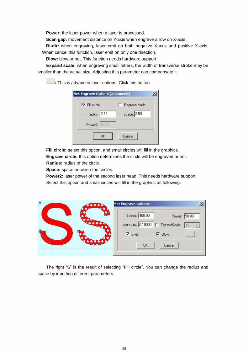
: This is advanced layer options. Click this button.
Fill circle: select this option, and small circles will fill in the graphics.
Engrave circle: this option determines the circle will be engraved or not.
Radius: radius of the circle.
Space: space between the circles.
Power2: laser power of the second laser head. This needs hardware support.
Select this option and small circles will fill in the graphics as following.
The right “S” is the result of selecting “Fill circle”. You can change the radius and
space by inputting different parameters.

30
5.1.4 Interface of setting grade engrave options
Sketch map of grade engrave as following.
Dblclick the color bar on the “Layer” column, and the dialog box as shown below.
Speed: engraving speed on X-axis.
Scan gap: movement distance on Y-axis when engrave a row on X-axis.
Power: the laser power when a layer is processed. This parameter determines the
depth of the slope.
Min-Power: the lowest laser power when grade engraving.
Grade-width: the width of grade.
Bi-dir: when engraving, laser emit on both negative X-axis and positive X-axis.
When cancel this function, laser emit on only one direction.
Blow: blow or not. This function needs hardware support.
Repair: select this option and the engraved letters will be clearer.
Repair per: change the parameter will adjust the definition of the engraved letters.

31
5.1.5 Interface of setting hole options
Dblclick the color bar on the “Layer” column, and the dialog box as shown below.
Power: the laser power when a layer is processed.
Interval: the space between two adjacent holes.
Radiation time: delay time for a hole. It determines the size of holes.
Hole on center: hole on all the center of the close graphs.
Blow: blow or not. This function needs hardware support.
: This is advanced layer options. Click this button.
Power2: laser power of the second laser head. This needs hardware support.
All the defaults are last saved parameters.
5.2 Test
, , , , , : Move the axis.

32
, : Click this button and the laser head (or Z) will move to the home
point of the machine slowly (the speed is determined by “Datum Speed” that you can
change in the Option” dialog box). Then the laser head will move to the origin point
quickly (the speed is determined by “Quick Speed” that you can change in the
“Option” dialog box). This can eliminate the cumulate error. Generally, the machine
should be reset before processing. When run the software, it will be reset
automatically (this function can be cancelled as you prefer).
Slow: No use.
Step: No use.
Length: No use.
Power: It determines the intensity of the laser power supply. The minimum value is
0 and the maximum value is 100.
: Laser on/off.
5.3 Auxiliary processing parameters
In the following dialog box, some auxiliary processing parameters can be set.
Times and Delay: If input 10 in “Times” and 20 in “Delay”, then press ”Run”, you
can get 10 same graphics. And it will stay for 20 seconds after every processing finished.
The 20 seconds is for feeding and taking down material. Different time can be set as you
need. This function can increase efficiency a lot.
Immediate: If this option is selected, the software will take the position that the laser
head is as original point. If this option is not selected, the original point will be the position
you set.
: Click this button, and laser head will move as a rectangle without laser
emitting according to the size of the graphics. This function is used for confirming the
location of work piece.
: Click this button, laser head will move as a rectangle with laser on
according to the size of the graphics. This function is also used for confirming the
location of work piece. Click this button, and you can see the following dialog box:

33
Speed: you can choose different speed according to different material. It’s better to
confirm proper speed through testing.
Power: the laser power when cutting.
Blank: distance between processing graphics and the edge of cutting piece.
Save: save the parameters for next data.
: This is advanced layer options. Click this button.
Length (feeding length): When input a certain number in it, feeding motor will give
a certain space after every processing finished. This function needs hardware support.
Speed (feeding speed): It set the feeding speed.
Delay: After X-Y finished, the machine will delay a certain time before feeding.
5.4 Download data
5.4.1 Download CFG

34
Download all the parameters of “Options” to MPC6515 controller. You can also
achieve this by exporting a CFG file (*.mol), and copy this file to MPC6515 by USB disk.
When modify the parameters of “Options” or update the firmware, you have to reset CFG
to configure the machine settings.
5.4.2 Download current file
Download the current processing data to MPC6515 controller.
5.4.3 Download file
Download processing data to MPC6515 controller.
5.4.4 Del
Delete the file which is selected.
5.4.5 Del all
Delete all the files in MPC6515 controller.
5.4.6 Export Cfg
This will create a *.mol file which includes all the parameters of “Options”. The file
can be downloaded to MPC6515 controller by USB disk.
5.4.7 Export file
This will create a *.mol file which includes all the parameters of a processing data.
The file can be downloaded to MPC6515 by USB disk.

35
Chapter 6 Options
Any change of the parameters in “Options” will change the performance of the
machine. Before changing the parameter, you should consult the supplier.
6.1 Main interface
6.1.1 Information about manufacturer
It shows the basic information about the manufacturer and can’t be modified.
6.1.2 Elapse time
It shows the time that the machine has run. It can’t be modified.
6.1.3 Other options
Use advanced options: There are advanced button as in “Laser output”. Some
accessorial parameters will help you get better effect. But it will make the software more
complex. Cancel this option, and you can’t inter the interface of “advanced options”.
With Feed components: This is for feeding axis. If the machine has not feeding axis,
this option should be canceled.
Auto Datum…: If you input a number in it, the machine will datum when the run time
reaches the number. It can eliminate the cumulate error of the mechanism.

36
6.2 Worktable
6.2.1 Pulse unit
It means the distance that the laser head moves when the control system output a
pulse. If you don’t know this numerical value, please click .
Move: When the stepping motor moves a circuit, the laser head will move a relative
length. You need to input the number in it.
Need pulse: The number is “driver’s subdivision number” ×200.
6.2.2 Range
It is the available processing area of the machine. If you change the number, the
reference frame of the main interface will be changed accordingly. The moving range of
the 1st and the 2nd axis will be restricted by this parameter.
6.2.3 Datum Dir (Datum Direction)
. It is determined by the position (right or left, up 0r down) of original switch.
6.2.4 Auto datum
If you select this function, when you run the software, it will be reset automatically.
The software can remember the coordinates of laser head. So you can move the laser
head very quickly without worrying that it will overstep the worktable. If this function is
canceled, you can only move the laser head slowly (the speed is “slow speed” and you
can change it the “machine parameter setting” dialog box). And when you move the laser
head, you have to be very careful to avoid striking the machine.

37
6.2.5 Datum Speed
It determines the speed of datum.
6.2.6 Start Speed
It is the start speed of all axes. Normally, the number should be chosen from
5-30mm/s according to different machines. If the number set up is too high, machine will
shake intensively.
6.2.7 Const Speed
When cutting, if the (processing) speed is higher than even speed, the laser head
will slow down on corners of the graphics. If the (processing) speed is lower than even
speed, the laser head will not change speed during processing.
6.2.8 Quick Speed
This is the maximum speed of laser head moving without lasers emitting. When
move the laser head up, down, left and right, this parameter will work. If the number is
too high, machine will shake intensively.
6.2.9 Acceleration
It is the acceleration from start speed to quick speed.
6.2.10 Test Speed (fast)
This is the speed that you move the laser head when you select auto datum.
6.2.11 Test Speed (slow)
This is the speed that you move the laser head when you don’t select auto datum.
6.2.12 Laser space
If there are 2 laser heads, the space of the laser heads should be input.
6.3 Feeding
The feeding axis can be used as feeding and lift working table.
6.3.1 Pulse unit
It means the distance that the laser head moves when the control system output a
pulse. If you don’t know this numerical value, please click .

38
Move: When the stepping motor moves a circuit, the laser head will move a relative
length. You need to input the number in it.
Need pulse: The number is “driver’s subdivision number” ×200.
6.3.2 Range
It is the available processing area of the feeding axis. The moving range of the
feeding axis will be restricted by this parameter.
6.3.3 Datum Direction
It is determined by the position (up 0r down) of original switch.
6.3.4 Auto Datum
If you select this function, when you run the software, the feeding axis will be reset
automatically. The software can remember the location of the feeding axis. So you can
move the feeding axis very quickly without worrying that it will overstep the worktable. If
this function is canceled, you can only move the feeding axis slowly (the speed is “slow
velocity” and you can change it the “machine parameter setting” dialog box). And when
you move the feeding axis, you have to be very careful to avoid striking the machine.
6.3.5 Datum Speed
It determines the speed of datum.
6.3.6 Start Speed
It is the start speed of all axes. Normally, the number should be chosen from
5-30mm/s according to different machines. If the number set up is too high, machine will
shake intensively.
6.3.7 Quick Speed
This is the maximum speed of laser head moving without lasers emitting. When
move the laser head up, down, left and right, this parameter will work. If the number is
too high, machine will shake intensively.
6.3.8 Acceleration
It is the acceleration from begin speed to fast speed.
6.3.9 Test Speed (fast)
This is the speed that you move the laser head when you select auto datum.
6.3.10 Test Speed (slow)
This is the speed that you move the laser head when you don’t select auto datum.

39
6.4 Cut
6.4.1 PWM Frequency
It determines the frequency of PWM signal.
6.4.2 Curve Disperse
It determines the precision of graph data. If the number is smaller, the precision will
be higher and cost more time to calculate processing data.
6.4.3 Min close-gas time
When the time between the former blowing off and the next blowing on is less than
the number, the machine will not blow off to protect the blowing switch.
6.4.4 Corner acc
It determines the processing precise when the processing route turns the corner.
When the machine can’t draw lines smoothly, please input a smaller number in
“Acceleration” and “Corner Acc”.
6.4.5 Gap on xy axis
Compensation gap when the motor changes direction. This parameter only works
when cut with even speed.
6.4.6 Original
The machine draws the graph according the route as it is been made.
6.4.7 Optimize
The software will calculate the route to improve processing efficiency. If you select
this option, there are 2 options.
Inner-to-outer: cut from inner to outer.
Down-to-up: cut from down to up according the number of “divide-height”.
6.4.8 Gap-Optimize
Select this option, when cut complex graphics, the software will generate cut route
to compensate the mechanical gap. But this will greatly increase inefficient route.
6.4.9 Automation set cut direction

40
The software will confirm the direction automatically. If you need to change the
direction, please cancel this function. Compensation
6.4.10 Overlap length
Because of the mechanical gap, circle can’t be cut round. Input a certain number in
it, and you can get the circle more round. But this will increase the processing time.
6.4.11 Circle speed
When cutting small circle (the diameter is especially between 1to 3) with high speed,
it will be distorted. The parameters of “Set circle speed” are used to reduce distortion.
Double-click ether row of the list.
When the radius of circle is in the range between “Min radius” and “Max radius”, the
cut speed will automatically be changed to the number of “Cut speed”.
6.5 Engrave
6.5.1 PWM Frequency
It determines the frequency of PWM signal.
6.5.2 Engrave
Select the engrave direction.
6.5.3 Engrave options
Double-click ether row of the list.

41
Begin Speed and End Speed: When the engrave speed is set in the range
between Begin Speed and End Speed, the system will automatically apply the numbers
of Acc Length, Backlash…
Acc length: It is the engraving length without laser emitting. It determines the
distance that the X-axis moves from start speed to (working) speed. If it is not long
enough, the machine will shake intensively.
Backlash: It is used for compensating mechanical gaps. If the engraving edge is not
orderly, please set up number in “Backlash”. This number can be positive or negative.
X start speed: It is the start speed of X-axis when engraving.
X acc: It is the acceleration of X-axis from start speed to (working) speed.
Y speed: It is the speed of Y-axis when engraving.
Y acc: It is the acceleration of Y-axis from start speed to “Y Speed”.
If you find graphics error happens (that is, motor lost step), you can set up a bigger
number in “Accelerator Length” or a smaller number in “Acceleration”.
X offset: when engraving graph is not be the actual position. There is an offset.
Input the offset is OK.
Y offset: when engraving graph is not be the actual position. There is an offset.
Input the offset is OK.
6.6 Grade Engrave
Please refer to 6.5
42
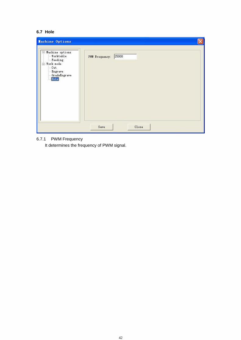
6.7 Hole
6.7.1 PWM Frequency
It determines the frequency of PWM signal.

43
Chapter 7 PAD03 Operation
7.1 Main interface of PAD03
Datum: Laser head will move to the original point of the machine slowly.
Laser: Laser on/off.
Stop: Cease the processing operation.
Test: The laser head will run along the outline border of the processing data.
Start/Pause: Start/pause the processing operation.
Esc: Escape the current status window.
Menu: Enter accessory interface.
: Click this button, then and can move the Z axis. This function needs
hardware (machine) support.
: Enter.
7.1.1 Startup interface
When power on, PAD will show” System starting, please wait”.
7.1.2 Main interface
The main interface shows as following.
FILE
SPEED 100%
POWER 100 / 100%
PIECES 1 DEL
AAA

44
File: File names which are saved in MPC6515 controller. Speed: Percentage of speed. When it is 100, the actual speed is the number which
is set in processing data. Power: Percentage of power. When it is 100, the actual power is the number which
is set in processing data. There are two options: the former is for “Corner -Power” and the latter for “Power”.
Pieces: Repeat times of a file.
Del: Delete the current file.
At first, file name is brightened (word is white and background is black). Now,
Press and , and you can select the option you want to modify. Press and , and you can change the number in the selected option.
Press and all the number will be saved. Press “Esc” and all the options will not be modified (none of the options is brightened). Now, press and you can move the laser head.
Press again and you can modify the options (file name is brightened).
7.2 Processing interface of PAD03
Press “Start” and the interface will show as following.
File: File name which is being processed. Speed: Percentage of speed. Power: Percentage of power. Time: Time for processing this file.
When processing, Press and , and you can change the percentage of power (only for Power, not for Corner -Power). Press and , and you can change the percentage of speed. Press “Start/Pause” and you can control the processing procedure. Press “Stop” and you can cancel the processing procedure. The interface shows “Stopped”. Press “Esc” and you can see the main interface.
7.3 Accessory interface of PAD03
Press “Menu” and you can see the accessory interface.
CUT BDR: Laser head will move a rectangle with laser on according to the size of the graphics.
FILE AAA
SPEED 100%
POWER 100 / 100%
TIME 0 :0 :15
LAS SET
PMOV SET
LANGUAGE
CUT BDR

45
LAS SET: Select this option and press . The LAS SET interface is as following. Press or can move the cursor. Press or can change the number.
Press and all the number will be saved. If this time is 0, press “Laser” key and laser on; release “Laser” key and laser off. If this time is not 0, press “Laser” key, and laser will shoot a certain time as you set.
PMOV SET: Select this option and press . The PMOV SET interface is as following.
Press or can change the number.
Press and all the number will be saved. If this number is 0, press the direction keys, and the laser head will move; release
the direction keys, and the laser head will stop. If this number is not 0, press the direction keys, and the laser head will move a
distance as you set.
LANGUAGE: Select this option and press . The language interface is as following.
Select the language as you prefer.
LASER TIME SET
MS
POWER SET
%
000000
DISTANCE SET
MM
简体中文
繁体中文
ENGLISH
000000
000000
46
Chapter 8 Text display operation
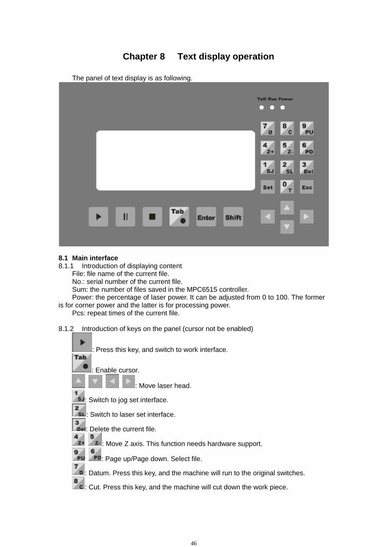
The panel of text display is as following.
8.1 Main interface 8.1.1 Introduction of displaying content
File: file name of the current file. No.: serial number of the current file. Sum: the number of files saved in the MPC6515 controller. Power: the percentage of laser power. It can be adjusted from 0 to 100. The former
is for corner power and the latter is for processing power. Pcs: repeat times of the current file.
8.1.2 Introduction of keys on the panel (cursor not be enabled)
: Press this key, and switch to work interface.
: Enable cursor.
: Move laser head.
: Switch to jog set interface.
: Switch to laser set interface.
: Delete the current file.
: Move Z axis. This function needs hardware support.
: Page up/Page down. Select file.
: Datum. Press this key, and the machine will run to the original switches.
: Cut. Press this key, and the machine will cut down the work piece.

47
8.1.3 Introduction of keys on the panel (cursor is enabled)
: Move cursor to the option that you want to change the number. After input
the number, please click to save it.
: Save the input number.
: Reset the number to 0.
8.2 Jog set interface
Press to input number and press to save it. The default is 0. If this number is 0, press the direction keys, and the laser head will move; release
the direction keys, and the laser head will stop. If this number is not 0, press the direction keys, and the laser head will move a
distance as you set.
8.3 Laser set interface
Press to input number and press to save it. The default is 0. If this time is 0, press “Laser” key and laser on; release “Laser” key and laser off. If this time is not 0, press “Laser” key, and laser will shoot a certain time as you set.
8.4 Work interface File: File name which is being processed. Speed: Percentage of speed. Power: Percentage of power. Time: Time for processing this file.
When processing,
Press and you can change the percentage of power (only for Power, not for Corner -Power).
Press and you can change the percentage of speed.
Press and you can control the processing procedure.
Jog Set
Distance: mm
Laser Set
Time: ms
Power: %
000000
000000
000000

48
Chapter 9 Download files
You can download update files, processing files and configuration files by USB disk conveniently.
9.1 Update MPC6515
9.1.1 Copy the latest firmware files (*.FMW and *.HDW) to the root directory of USB
disk. The USB disk should be formatted to FAT. And it is suggested that other files should
not be saved in this USB disk.
9.1.2 Power on MPC6515 controller and the indicator light (D3 on MPC6515/CPU) will
flash 2 times.
9.1.3 After the indicator light (D3 on MPC6515/CPU) flashes 2 times, plug the USB
disk in MPC6515 quickly (don’t exceed 5 seconds).
9.1.4 The indicator light (D3 on MPC6515/CPU) will shine continuously 2-5 seconds.
Now, MPC6515 is updating firmware.
9.1.5 If the updating procedure is finished, the indicator light (D3 on MPC6515/CPU)
would flash frequently.
9.1.6 Pull out the USB disk, and MPC6515 will run new firmware program
automatically.
9.1.7 After MPC6515 is updated, the CFG file should be downloaded again. Please
refer to “5.4 Download data” for detailed information.
If MPC6515 can’t run normally, you may make a mistake when updating. You can
repeat the above steps. If this doesn’t work, please contract the equipment supplier.
9.2 Download processing file (*.mol)
There are 2 ways to download processing file to MPC6515 controller.
One is by USB data line. If the computer is close to the machine, this way is very
conveniently. Please refer to “5.4 Download data” for detailed information.
The other is by USB disk. If you have two or more machines, this way is very
conveniently. The following is the detailed steps.
9.2.1 Copy the processing file (*.mol) to the root directory of USB disk. The USB disk
should be formatted to FAT16. And it is suggested that other files should not be saved in
this USB disk.
9.2.2 Power on MPC6515 controller.
You need update MPC6515 only when new version is issued.
Notice
Those USB disk with indicate light is suggested for it is convenient to check whether the download procedure is finished or not.
Notice

49
9.2.3 Plug USB disk in MPC6515 controller. 9.2.4 The indicator light (D3 on MPC6515/CPU) will shine continuously 2-10 seconds. If the file is too large, it will take several minutes. Now, MPC6515 is downloading file.
9.2.5 If the downloading procedure is finished, the indicator light (D3 on
MPC6515/CPU) would flash frequently. And the PAD03 will give an alarm.
9.2.6 Pull out the USB disk, and you can run the files by PAD03.
If the file is a configuration file, the new parameters will be effective after you run this file by PAD03. If the file is a processing data file, you can run it by PAD03 directly.
Notice
If it is the first time to use the MPC6515, you have to download the configuration file and run it. If some parameters are changed, the same operation should be finished.
Notice

50
Chapter 10 Comments on tool programs
Tool programs are for checking if the control card is normal. It is helpful to find where
the trouble is quickly.
10.1 Version check program
If the version numbers of card and DLL don’t match, the card won’t work normally.
Generally, the version numbers of card can’t be changed (unless update the firmware).
Proper DLL has to be found out to match the card. Version check program can indicate
the version numbers of card and DLL.
DLL is laid in [Lasercut50], and the filename is MPC05ls.dll.
Version check program is laid in [Lasercut50], and the filename is
Mpc05Ver+M05.exe.
Run the program, if the version numbers are match, it is as shown below.
Note down the version numbers of card and DLL, and get the proper DLL from the
supplier.

51
Chapter 11 Addenda
11.1 How to make AI (Adobe Illustrator) file
AI file is smoother than PLT file. When cutting, it is suggested to input AI files. When
export data in CorelDraw, the file type should be selected as AI(Adobe Illustrator). The
options should be selected as following.
11.2 FAQ
11.2.1 When grade engraving, the graph is superposition.
This always occurs when the graph is very small. Please input a smaller number in
“Grade width”.
11.2.2 PLT graph can’t be engraved
Please check if the graph is closed. The software only engrave closed graph.
Please check if there are two same graphs superpose together.
11.2.3 The size of output is not as same as the graph
Please adjust the “Pulse Unit”.
11.2.4 When engraving, the edge is not in order
This is caused by the mechanical gap.
Draw a rectangle, and set the mode as “Engrave”. Parameters should be set as the
following dialog box.
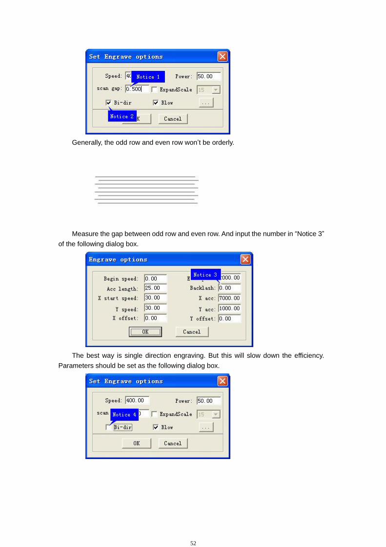
52
Generally, the odd row and even row won’t be orderly.
Measure the gap between odd row and even row. And input the number in “Notice 3”
of the following dialog box.
The best way is single direction engraving. But this will slow down the efficiency.
Parameters should be set as the following dialog box.
Related Documents