CENTAURI ENERGY SERVER User Manual Model number: GF-20000-360Vdc-380Vac-3/3 Version 1.0; Release Date: October2019 Author: Mamoona Khalid (BS-EE, MS-EEE)

Welcome message from author
This document is posted to help you gain knowledge. Please leave a comment to let me know what you think about it! Share it to your friends and learn new things together.
Transcript

CENTAURI ENERGY SERVER
User Manual
Model number: GF-20000-360Vdc-380Vac-3/3
Version 1.0; Release Date: October2019
Author:
Mamoona Khalid
(BS-EE, MS-EEE)

Introduction
The Centauri Energy Server is the first comprehensive, stand-alone, fully integrated power electronics
hardware + software platform that delivers utility grade power from any combination of DC or AC
generation sources and storage. The Centauri replaces integrated systems comprised of multiple
components (PV inverter + charge controller + battery inverter + communication software and
hardware + safety devices etc.) and can be deployed in any location, to service any kind of load profile
(from kW to MW), with or without grid access or generator availability.
The Centauri Energy Server is equipped with high speed digital DSP core control devices, advanced
high-speed IBGT, MOSFET and other power devices, combined with disturbance type (SVPWM) MPPT
control technology with pulse width modulation and double transformation system so that it can
quickly track the polar plate for the control system of high power, load change and high efficient
multiple levels under the control of the high speed DSP system to provide the load with high quality
power supply featuring stable voltage and frequency even in the cases of a sudden change of AC input
voltage and AC frequency, over/under voltage.
Legal Provisions
No part of this User Manual (“Manual”) may be reproduced, or transmitted, in any form or by any
means, without the prior written permission of Kilowatt Labs, Inc. (“Kilowatt” or the “Company”).
Specifications in this Manual are subject to change without notice. While every attempt has been
made to make the Manual accurate and up-to-date, users are cautioned that product improvements
may cause the Company to make changes to specifications without advance notice. Users are
encouraged to consult the Company or its Resellers before using the Manual. Neither the Company
nor its Resellers shall be liable for any indirect, incidental, or consequential damages under any
circumstances caused by reliance on the material presented, including, but not limited to, omissions,
typographical errors, arithmetical errors or listing errors in the content material. The content of this
manual shall not be modified without the written authorization of the Company.
Trademarks
All trademarks are recognized, even if not explicitly identified as such. Kilowatt Labs® is a registered
trademark of the Company.

Centauri Energy Server – User Manual Model Number - GF-20000-360Vdc-380Vac-3/3 This manual is subject to change without notice and at the sole discretion of Kilowatt Labs, Inc.
Kilowatt Labs, Inc. | www.kilowattlabs.com
3
Table of Contents: 1. Safety Precautions: ......................................................................................................................... 7
2. Energy Server Overview: ................................................................................................................. 8
2.1 Part Number: ................................................................................................................................. 8
2.2 Production Profile: ........................................................................................................................ 8
2.3 System Architecture of Product: ................................................................................................... 9
3 Description of Product Control: ......................................................................................................... 10
3.1 Control Panel: .............................................................................................................................. 10
3.2 Description of Touch Screen: ...................................................................................................... 10
3.3 STATUS (System Warning LED) and Warning: ............................................................................. 14
3.4 Introduction of Buttons: ............................................................................................................. 15
3.4.1 Description of Selection Button Function: ............................................................................ 15
3.4.2 Description of Function Buttons: .......................................................................................... 16
3.5 Introduction of Breaker: ............................................................................................................. 17
3.6 Introduction to Line Bank: .......................................................................................................... 18
3.7 Description of Remote-Control Signal Input: .............................................................................. 18
3.8 Description of Output Signal at System Dry Contact: ................................................................. 19
4. Storage and Installation of Energy Server:........................................................................................ 20
4.1 Storage: ....................................................................................................................................... 20
4.2 Installation Notices: .................................................................................................................... 20
4.3 Unpacking and Content Check: ................................................................................................... 21
4.4 Determination of Mounting Positions: ....................................................................................... 21
4.5 Cabinet Handling: ........................................................................................................................ 22
4.6 Requirements of Battery Configuration: ..................................................................................... 23
4.7 Incoming Line Way of System: .................................................................................................... 24
4.8 Requirements of External Distribution: ...................................................................................... 24
4.9 Power Cable: ............................................................................................................................... 25
4.10 System Wiring: .......................................................................................................................... 26
4.11 Communication Interface: ........................................................................................................ 27
4.12 Signal Interface: ........................................................................................................................ 27
5. Operating Instructions: ..................................................................................................................... 29
5.1 Daily ON/OFF: .............................................................................................................................. 29
5.1.1 Daily on Steps: ....................................................................................................................... 29
5.1.2 Daily OFF Steps: ..................................................................................................................... 30

Centauri Energy Server – User Manual Model Number - GF-20000-360Vdc-380Vac-3/3
This manual is subject to change without notice and at the sole discretion of Kilowatt Labs, Inc. Kilowatt Labs, Inc. | www.kilowattlabs.com
4
5.2 Emergency Stop Operation: ........................................................................................................ 30
5.3 Clear Operation for System Fault: ............................................................................................... 30
5.4 Operation Steps of MaintenanceBypass:……………………………………………………………………………………33
5.4.1 Manual Bypass ON: ............................................................................................................... 31
5.4.2 Entering Service Mode: ......................................................................................................... 31
5.5 System Setup: .............................................................................................................................. 32
5.5.1 Advanced Setup: ...................................................................................................................... 32
5.5.1.1 System Mode setting: ......................................................................................................... 33
5.5.1.2 PV Auto Power-ON Setting: ................................................................................................ 33
5.5.1.3 Input Setup of Battery Parameters: ................................................................................... 33
5.5.1.4 Password Setting: ............................................................................................................... 34
5.5.1.5 Other Settings: .................................................................................................................... 35
5.5.2 User Setup: ............................................................................................................................... 35
5.5.2.1 MPPT Setup: ....................................................................................................................... 35
5.5.2.2 INV Setup: ........................................................................................................................... 35
5.5.2.3 Off-Peak Setup: ................................................................................................................... 35
5.5.2.4 Protocol Setup: ................................................................................................................... 36
5.5.2.5 Language Selection: ............................................................................................................ 36
5.5.2.6 Setup of Date and Time: ..................................................................................................... 36
5.5.2.7 Setup of Date Format: ........................................................................................................ 36
5.5.2.8 User Password/Control Password: ..................................................................................... 36
5.5.2.9 Touch Screen Calibration: .................................................................................................. 36
6. Description of Working Principle: ..................................................................................................... 37
6.1 PV and AC normal: ...................................................................................................................... 37
6.2 AC abnormal or Absent: .............................................................................................................. 38
6.3 Off-Peak Power Consumption: .................................................................................................... 39
6.4 System failure: ............................................................................................................................ 40
7. Maintenance: .................................................................................................................................... 41
7.1 Preventive Maintenance: ............................................................................................................ 41
7.2 Maintenance of Battery: ............................................................................................................. 41
7.3Troubleshooting:……………………………………………………………………………….………..………………………….45
7.3.1 Common Troubleshooting: .................................................................................................... 42
7.3.2 MPPT Troubleshooting: ......................................................................................................... 46

Centauri Energy Server – User Manual Model Number - GF-20000-360Vdc-380Vac-3/3
This manual is subject to change without notice and at the sole discretion of Kilowatt Labs, Inc. Kilowatt Labs, Inc. | www.kilowattlabs.com
5
Table of Figures:
Fig 1 Composition of Off-grid Photovoltaic System ................................................................................ 9
Fig 2 System Architecture of Product ..................................................................................................... 9
Fig 3 System Control Panel ................................................................................................................... 10
Fig 4 Description of Touch Screen ......................................................................................................... 10
Fig 5 Schematic Diagram of System Installation ................................................................................... 22
Figure 6 Schematic Diagram of System Handling ................................................................................. 23
Fig 7 Signal Interface of Remote Control .............................................................................................. 28
Fig 8 Signal Interface of Output Dry Contact ........................................................................................ 28
Fig 9 Normal Mode 1 of PV and AC ....................................................................................................... 37
Fig 10 Normal Mode 2 of PV and AC ..................................................................................................... 37
Fig 11 AC Abnormal Mode 1 ................................................................................................................. 38
Fig 12 AC Abnormal Mode 2 ................................................................................................................. 38
Fig 13 Off-Peak Setup Mode 1 .............................................................................................................. 39
Fig 14 Off-Peak Setup Mode 2 .............................................................................................................. 39
Fig 15 Off-Peak Setup Mode 3 .............................................................................................................. 40
Fig 16 Mode 4 for Off-peak Electricity Consumption ........................................................................... 40
Centauri Energy Server – User Manual Model Number - GF-20000-360Vdc-380Vac-3/3
This manual is subject to change without notice and at the sole discretion of Kilowatt Labs, Inc. Kilowatt Labs, Inc. | www.kilowattlabs.com
6
Table of Tables:
Table 1a Description of Menu Icon of touch screen ............................................................................. 12
Table 1b Description of Button Symbol of touch screen ...................................................................... 14
Table 2a System LED and Alarm 1 ......................................................................................................... 15
Table 2b System LED and Alarm 2 ........................................................................................................ 15
Table 3 Description of selection Buttons .............................................................................................. 16
Table 4 Description of Function Buttons .............................................................................................. 16
Table 5 Introduction of Breaker ............................................................................................................ 17
Table 6 Description of Line Bank ........................................................................................................... 18
Table 7 Description of Remote-Control Signal Input ............................................................................ 19
Table 8 Description of Output Signal at System Dry Contract .............................................................. 19
Table 9 Reference List of Power Cable ................................................................................................. 26
Table 10 Comparison Table of Common Faults .................................................................................... 45
Table 11 MPPT Warning Information ................................................................................................... 47

Centauri Energy Server – User Manual Model Number - GF-20000-360Vdc-380Vac-3/3
This manual is subject to change without notice and at the sole discretion of Kilowatt Labs, Inc. Kilowatt Labs, Inc. | www.kilowattlabs.com
7
1. Safety Precautions:
Please comply with the following precautions for safe use:
• Installation and maintenance must be done only by authorized technicians.
• During the installation of this product, the distance between the Energy Server and the wall
should be more than 300 mm to ensure ventilation and heat dissipation of the system.
• The temperature of the surface of the cabinet may rise when the product is in normal operation.
• Since the battery packs of all series inverters are external, the product should be equipped with
the battery packs which should meet the requirements of the rated voltage of the equipment
when in operation.
• Do not open the cabinet of the inverter, otherwise it may cause an electric shock.
• The internal inspection and maintenance should be conducted only by the authorized technical
personnel.
• After the Energy Server is turned OFF, its voltage may be still high for a long time, please do not
open the cabinet because it may cause an electric shock.
• The “Manual Bypass” switch is used for maintenance and repair of the product; therefore,
authorized technical personnel should open it.
• This system is provided with multiple PV inputs; therefore, it should be connected with the
independent loop, without the electrode grounded.
• The “EPO” button on the panel is used for the emergency stop power supply (power off) of the
Energy Server, please pay attention to its operation.
• The internal short circuit of the Energy Server will lead to the risk of an electric shock or a fire,
therefore under no circumstances should liquids be placed on it in order to avoid electric shock
or other hazards.
• Please use the dry powder fire extinguishers in the event of a fire, because the use of the liquid
fire extinguisher may cause an electric shock.
• Please install the external power switch near the Energy Server so that the power supply can be
cut OFF in the event of emergency.
• Do not store or install the Energy Server:
→ Outdoors.
→ In locations without cross ventilation.
→ In locations near or where there is combustible gas, corrosive substances or dust.
→ In locations with unusually high or low temperatures (above 40oC or below 0oC) or high

Centauri Energy Server – User Manual Model Number - GF-20000-360Vdc-380Vac-3/3
This manual is subject to change without notice and at the sole discretion of Kilowatt Labs, Inc. Kilowatt Labs, Inc. | www.kilowattlabs.com
8
humidity (90%).
2. Energy Server Overview:
2.1 Part Number:
1. Isolated Off-Grid Type
2. Capacity of Energy Server in W
3. DC Input Voltage
4. AC Output Voltage:
5. 3/3 System Input/output
2.2 Production Profile:
The OFF-grid photovoltaic power generation system mainly consists of the PV Panels, combiner box,
Energy Server, Battery and Load. The solar energy of the PV panels is sent to the combiner, after
converging, solar energy is sent to the PV input of the Energy Server, where it changes the DC into AC
to feed the load. At the same time, the Energy Server also changes AC into DC by rectifier and change
the DC into AC to the load as shown in Fig 1.
Warning!
1. The Energy Server must be reliably grounded.
2. The loss caused by the improper operation may be huge, please operate
the equipment by following the requirements of specifications.

Centauri Energy Server – User Manual Model Number - GF-20000-360Vdc-380Vac-3/3
This manual is subject to change without notice and at the sole discretion of Kilowatt Labs, Inc. Kilowatt Labs, Inc. | www.kilowattlabs.com
9
Fig 1 Composition of Off-grid Photovoltaic System
2.3 System Architecture of Product:
Fig 2 System Architecture of Product
Centauri Energy Server – User Manual Model Number - GF-20000-360Vdc-380Vac-3/3
This manual is subject to change without notice and at the sole discretion of Kilowatt Labs, Inc. Kilowatt Labs, Inc. | www.kilowattlabs.com
10
3 Description of Product Control:
3.1 Control Panel:
Fig 3 System Control Panel
3.2 Description of Touch Screen:
Fig 4 Description of Touch Screen

Centauri Energy Server – User Manual Model Number - GF-20000-360Vdc-380Vac-3/3
This manual is subject to change without notice and at the sole discretion of Kilowatt Labs, Inc. Kilowatt Labs, Inc. | www.kilowattlabs.com
11
Menu Icon Menu Name Menu Items
Definition
Input Parameters Line Voltage(V) Input line voltage of rectifier
Current (A) Input current of rectifier
Frequency (Hz) Input frequency of rectifier
Power factor Input power factor of
rectifier
Bypass parameters Phase voltage (V) Phase voltage
Frequency (HZ) Frequency
Output parameters Phase Voltage(V) Output phase voltage of
inverter
Phase Current (A) Output phase current of
inverter
Frequency (HZ) Output frequency of
inverter
Power factor Power factor of load
Load parameters
Apparent Power
(KVA)
S out: Apparent power
Active power (KW) P out: Active power
Load percentages
(%)
Load (Energy Server, shows
by the rated load
percentage)
Parallel machine
parameters
Apparent Power
(KVA)
S out: Apparent power
Active power (KW) P out: Active power
Single machine
system without
parallel machine
data
When the Energy Server is
set as a single machine, it
only includes its own load
instead of the system load.
Battery Parameters DC BUS voltage (V) Operating voltage of system
DC BUS
Centauri Energy Server – User Manual Model Number - GF-20000-360Vdc-380Vac-3/3
This manual is subject to change without notice and at the sole discretion of Kilowatt Labs, Inc. Kilowatt Labs, Inc. | www.kilowattlabs.com
12
Battery voltage (V) Voltage of system battery
pack
Battery Current (A) Battery charging and
discharging current
Battery
temperature
Ambient temperature of
current battery pack
Environment
temperature(t)
Environment temperature
inside the Energy Server
Battery Status Battery pack switch is
opened
System Generated
Energy
Generated power Current total system
generated power
Daily Generated
Energy
Daily gross generation of the
system
Gross Generation Accumulative gross
generation of the system
MPPT (1- n) Parameters Module version Module software version
PV voltage PV voltage input by MPPT
n# single Module
PV current PV current input by MPPT
n# single Module
Battery Voltage Battery voltage detected by
the current MPPT Module
Charging Current Current Battery charging
voltage
Module Status Current Module status
Table 1a Description of Menu Icon of touch screen
Centauri Energy Server – User Manual Model Number - GF-20000-360Vdc-380Vac-3/3
This manual is subject to change without notice and at the sole discretion of Kilowatt Labs, Inc. Kilowatt Labs, Inc. | www.kilowattlabs.com
13
Button Symbols Name Functions
Setup
Click this button to enter the
system setup interface.
ON/OFF
Click this button to execute
ON/OFF option and the
operation is effective after
confirmation.
Battery pack parameters
Click this button to view the
battery voltage and
charging/discharging cutout and
battery connection.
Input parameters of rectifier
Press this button to view the
operating parameters of the
rectifier.
Input parameters of bypass
Press this button to view the
bypass input operating
parameters.
O/P Output parameters
Press this button to view the
system output operating
parameters.
Battery self-check and
maintenance
Press this button to set battery
test or terminate the test.
History button
Press this button to view the
history of the Energy Server
system.
Skip button
Press this button to view
another data message in the
same directory.
Return to the main interface
The system will return to the
system main control interface by
pressing this button.
Return to the superior menu
The system will return to the
directory's superior menu by
pressing this button.
Page down button Page down button
Page up button Press this button to turn to the
front page.

Centauri Energy Server – User Manual Model Number - GF-20000-360Vdc-380Vac-3/3
This manual is subject to change without notice and at the sole discretion of Kilowatt Labs, Inc. Kilowatt Labs, Inc. | www.kilowattlabs.com
14
Left shift button Press the button to move one bit
to the left.
Right shift button Press the button to move one bit
to the right.
UP/DOWN switch button Press this button to skip
up/down.
OK button Press this button to confirm the
operation above.
Delete button Press this button to delete the
operation.
Table 1b Description of Button Symbol of touch screen
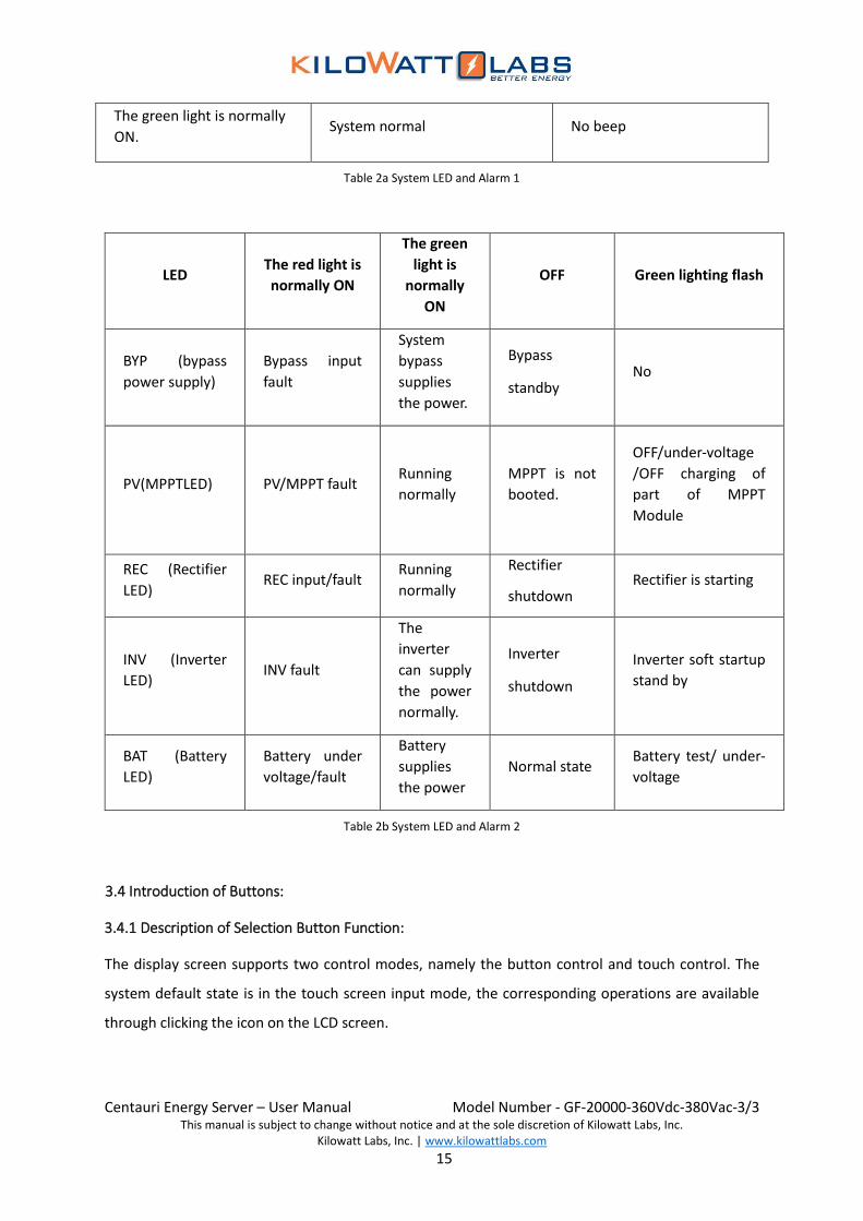
3.3 STATUS (System Warning LED) and Warning:
SYS-LED Status Function Description Buzzer Status
Red light being normally
ON
EPO, emergency stop
Along beep Communication fault
System fault
The red-light flashes once
per second
Low voltage of battery
A beep per second
The delay of bypass overload is
over
Overload timeout for this
machine
Fan fault
Output overload
The red-light flashes once
per 4 seconds
Other normal alarm
information A beep per 4 seconds
The red-light flashes once
per 2 seconds Battery test A beep per 2 seconds
Centauri Energy Server – User Manual Model Number - GF-20000-360Vdc-380Vac-3/3
This manual is subject to change without notice and at the sole discretion of Kilowatt Labs, Inc. Kilowatt Labs, Inc. | www.kilowattlabs.com
15
The green light is normally
ON. System normal No beep
Table 2a System LED and Alarm 1
LED The red light is
normally ON
The green
light is
normally
ON
OFF Green lighting flash
BYP (bypass
power supply)
Bypass input
fault
System
bypass
supplies
the power.
Bypass
standby No
PV(MPPTLED) PV/MPPT fault Running
normally
MPPT is not
booted.
OFF/under-voltage
/OFF charging of
part of MPPT
Module
REC (Rectifier
LED) REC input/fault
Running
normally
Rectifier
shutdown Rectifier is starting
INV (Inverter
LED) INV fault
The
inverter
can supply
the power
normally.
Inverter
shutdown
Inverter soft startup
stand by
BAT (Battery
LED)
Battery under
voltage/fault
Battery
supplies
the power
Normal state Battery test/ under-
voltage
Table 2b System LED and Alarm 2
13.4 Introduction of Buttons:
3.4.1 Description of Selection Button Function:
The display screen supports two control modes, namely the button control and touch control. The
system default state is in the touch screen input mode, the corresponding operations are available
through clicking the icon on the LCD screen.

Centauri Energy Server – User Manual Model Number - GF-20000-360Vdc-380Vac-3/3
This manual is subject to change without notice and at the sole discretion of Kilowatt Labs, Inc. Kilowatt Labs, Inc. | www.kilowattlabs.com
16
Table 3 Description of selection Buttons
• Click the “ ” button on any interface to switch to the button control mode, and then press the
“ ” button to return to the touch screen control mode.
• After clicking “ ” button, the user can move the cursor through pressing “ ” or “ ” button
to choose the required control button and then press the “ ” button for confirmation.
3.4.2 Description of Function Buttons:
Button Symbols Name Functions
INV ON ON button
When this button is pressed, the system
executes the boot command and then runs
after pressing the “OK” button.
INV OFF OFF button
When this button is pressed, the system
executes the shutdown command and the
shutdown operation is effective by pressing the
“OK” button. At this moment, the system and
the output shut down.
SILENCE ON/OFF Beep ON/OFF The system alarm is cancelled or activated by
pressing this button.
FAULT CLEAR Clear the system
fault
Press this button to clear executed abnormal
protection command, the system will restart
and run.
EPO Emergency stop When this button is pressed, the system
immediately put an end to the power supply.
Table 4 Description of Function Buttons
Centauri Energy Server – User Manual Model Number - GF-20000-360Vdc-380Vac-3/3
This manual is subject to change without notice and at the sole discretion of Kilowatt Labs, Inc. Kilowatt Labs, Inc. | www.kilowattlabs.com
17
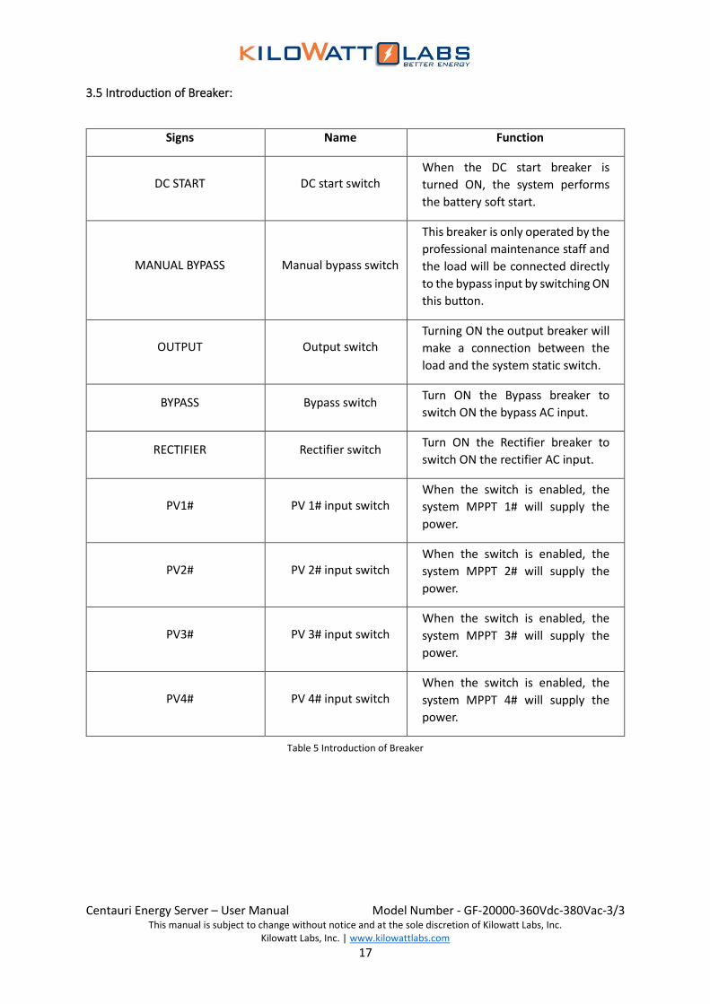
3.5 Introduction of Breaker:
Signs Name Function
DC START DC start switch When the DC start breaker is
turned ON, the system performs
the battery soft start.
MANUAL BYPASS Manual bypass switch
This breaker is only operated by the
professional maintenance staff and
the load will be connected directly
to the bypass input by switching ON
this button.
OUTPUT Output switch Turning ON the output breaker will
make a connection between the
load and the system static switch.
BYPASS Bypass switch Turn ON the Bypass breaker to
switch ON the bypass AC input.
RECTIFIER Rectifier switch Turn ON the Rectifier breaker to
switch ON the rectifier AC input.
PV1# PV 1# input switch When the switch is enabled, the
system MPPT 1# will supply the
power.
PV2# PV 2# input switch When the switch is enabled, the
system MPPT 2# will supply the
power.
PV3# PV 3# input switch When the switch is enabled, the
system MPPT 3# will supply the
power.
PV4# PV 4# input switch When the switch is enabled, the
system MPPT 4# will supply the
power.
Table 5 Introduction of Breaker
Centauri Energy Server – User Manual Model Number - GF-20000-360Vdc-380Vac-3/3
This manual is subject to change without notice and at the sole discretion of Kilowatt Labs, Inc. Kilowatt Labs, Inc. | www.kilowattlabs.com
18
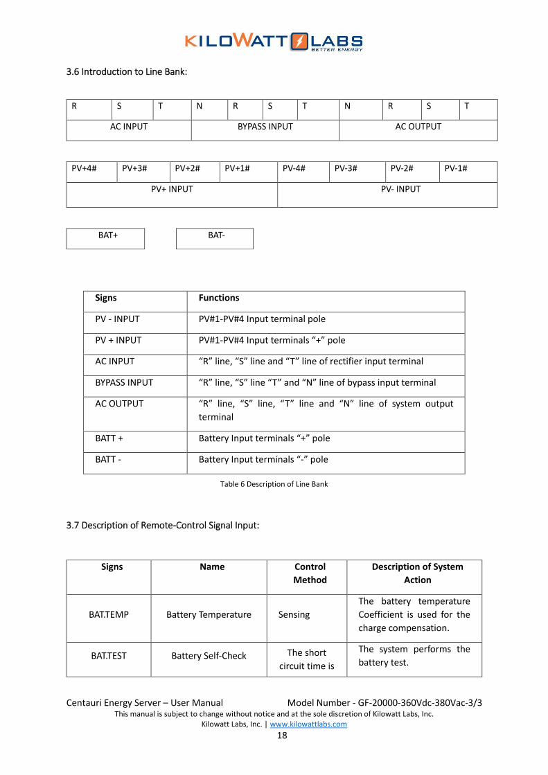
3.6 Introduction to Line Bank:
R S T N R S T N R S T
AC INPUT BYPASS INPUT AC OUTPUT
PV+4# PV+3# PV+2# PV+1# PV-4# PV-3# PV-2# PV-1#
PV+ INPUT PV- INPUT
BAT+
Signs Functions
PV - INPUT PV#1-PV#4 Input terminal pole
PV + INPUT PV#1-PV#4 Input terminals “+” pole
AC INPUT “R” line, “S” line and “T” line of rectifier input terminal
BYPASS INPUT “R” line, “S” line “T” and “N” line of bypass input terminal
AC OUTPUT “R” line, “S” line, “T” line and “N” line of system output
terminal
BATT + Battery Input terminals “+” pole
BATT - Battery Input terminals “-” pole
Table 6 Description of Line Bank
3.7 Description of Remote-Control Signal Input:
Signs Name Control
Method
Description of System
Action
BAT.TEMP Battery Temperature Sensing
The battery temperature
Coefficient is used for the
charge compensation.
BAT.TEST Battery Self-Check The short
circuit time is
The system performs the
battery test.
BAT-

Centauri Energy Server – User Manual Model Number - GF-20000-360Vdc-380Vac-3/3
This manual is subject to change without notice and at the sole discretion of Kilowatt Labs, Inc. Kilowatt Labs, Inc. | www.kilowattlabs.com
19
INVON System ON no less than
0.2s
The system turns ON.
INVOFF System OFF The system shuts down.
FAULT CLEAR Clear faults
Press this button to clear
executed abnormal
protection command, the
system will restart and run.
EPO Emergency stop The system stops.
Table 7 Description of Remote-Control Signal Input
3.8 Description of Output Signal at System Dry Contact:
English Name Chinese name Normally Closed
Nodes
Normally Opened
Nodes
FAN FAULT Fan fault Fan normal Fan fault
SYSALRAM System alarm No system
alarm System alarm
GENERATOR
ON/OFF Generator ON/OFF Generator OFF Generator ON
BAT LOW Battery low voltage
No low voltage
alarm for
battery
Battery low voltage
OVERLOAD Output overload Output normal Output overload
BYP FAULT Bypass fault Bypass input is
abnormal Bypass fault
AC FAULT Rectifier fault Rectifier input is
abnormal Rectifier fault
SYS FAULT System fault System is
normal System fault
Table 8 Description of Output Signal at System Dry Contract

Centauri Energy Server – User Manual Model Number - GF-20000-360Vdc-380Vac-3/3
This manual is subject to change without notice and at the sole discretion of Kilowatt Labs, Inc. Kilowatt Labs, Inc. | www.kilowattlabs.com
20
4. Storage and Installation of Energy Server:
4.1 Storage:
If the Energy Server is not to be installed immediately, please do not remove the packing, and store
the Energy Server vertically in a dry room facing towards sunshine according to the mark on the
packing box, and avoid dust and high temperature.
4.2 Installation Notices:
This section gives a general description of the requirements of the Energy Server for the site selection
and wire layout of the Energy Server.
• The installation site must be provided with the professional engineers authorized by the company
for the guidance of installation.
• Ground the Energy Server properly and turn OFF all switches before making electrical connections.
• The Energy Server should be installed by qualified engineers according to the descriptions in this
section following the local standards.
• When connecting the battery, the voltage at the battery terminal will be more than 360 VDC which
possesses the risk of the fatal danger.
→ Please take off the rings, bracelets, watches, and other metal jewelry.
→ Use tools having insulated handle(s).
→ Please wear rubber gloves.
→ If there is leakage of the battery electrolyte or the battery is broken, please replace the battery
and put it in the container with the resistance to sulfate corrosion and dispose it according to
the local regulations.
→ When your skin contacts the electrolyte, please wash it with water immediately.

Centauri Energy Server – User Manual Model Number - GF-20000-360Vdc-380Vac-3/3
This manual is subject to change without notice and at the sole discretion of Kilowatt Labs, Inc. Kilowatt Labs, Inc. | www.kilowattlabs.com
21
4.3 Unpacking and Content Check:
1. Centauri Energy Server
2. SNMP Card
3. RS232 Communication wire
• When unpacking the Energy Server, please make the inspections as follows:
• Make a visual inspection to make sure whether there is no deformation, damage and dislocation
or other damage in transportation on the internal or external surface of the Energy Server and the
battery. If there is any damage, do not install or use the system, please notify the carrier for
disposal immediately.
• Check the technical data sheet of the product to confirm whether it is the right equipment. The
technical data sheet of the Energy Server is located on the label in the internal side of the front
door, with the model, capacity and main parameters of the Energy Server indicated on the label.
4.4 Determination of Mounting Positions:
Please pay attention to the following requirements for the selection of the Energy Server’s installation
space.
2 1
3

Centauri Energy Server – User Manual Model Number - GF-20000-360Vdc-380Vac-3/3
This manual is subject to change without notice and at the sole discretion of Kilowatt Labs, Inc. Kilowatt Labs, Inc. | www.kilowattlabs.com
22
1) The Energy Server must be installed in clean and dry room (the environment temperature
within 0 ~ 40oC, the relative humidity of 5% ~ 90%, and the optimal operating temperature of 25oC).
If the room temperature is 40oC, the indoor exhaust fan should be installed to ensure sufficient air
flow in the room so that the equipment gets full heat dissipation in case of the rise in room
temperature. It is best to be equipped with A/C system.
2) To facilitate the wiring daily maintenance, diagnosis, and repair of the Energy Server, please
make sure that the safe space of the front and the back doors is reserved (The advisable space is 1000
mm or more to ensure that the door of the Energy Server can be fully opened, and the operators can
pass the door freely).
Fig 5 Schematic Diagram of System Installation
i. For altitude greater than 1000 meters, the derating of the Energy Server should be used.
ii. The bearing capability of the pallet should be greater than the equipment weight (The
equipment weight is as shown in the technical specifications).
4.5 Cabinet Handling:
First of all, remove the surrounding rat proof baffles below the machine, and then get the mechanical
arms of the special handling equipment (hoisting equipment, stackers or forklift) with the sufficient
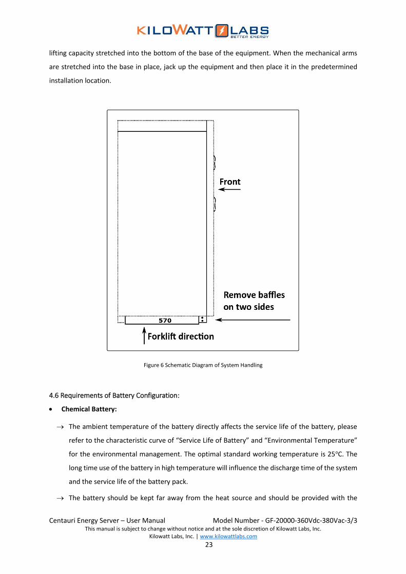
Centauri Energy Server – User Manual Model Number - GF-20000-360Vdc-380Vac-3/3
This manual is subject to change without notice and at the sole discretion of Kilowatt Labs, Inc. Kilowatt Labs, Inc. | www.kilowattlabs.com
23
lifting capacity stretched into the bottom of the base of the equipment. When the mechanical arms
are stretched into the base in place, jack up the equipment and then place it in the predetermined
installation location.
Figure 6 Schematic Diagram of System Handling
4.6 Requirements of Battery Configuration:
• Chemical Battery:
→ The ambient temperature of the battery directly affects the service life of the battery, please
refer to the characteristic curve of “Service Life of Battery” and “Environmental Temperature”
for the environmental management. The optimal standard working temperature is 25oC. The
long time use of the battery in high temperature will influence the discharge time of the system
and the service life of the battery pack.
→ The battery should be kept far away from the heat source and should be provided with the

Centauri Energy Server – User Manual Model Number - GF-20000-360Vdc-380Vac-3/3
This manual is subject to change without notice and at the sole discretion of Kilowatt Labs, Inc. Kilowatt Labs, Inc. | www.kilowattlabs.com
24
proper ventilation to avoid the generation of explosive hydrogen and oxygen mixed gas.
→ The battery switch should be installed close to the battery as much as possible and ensure that
the distance between the battery and the Energy Server is shortest as much as possible.
• Sirius Module:
→ Do not charge the Module when the temperature is below -30oC.
→ Do not charge the Module when temperature is above 80oC.
→ All Modules must be at 100% SOC or same voltage level before connecting in Series or in Parallel.
→ Modules cannot be connected in Series-Parallel combination under any circumstance.
4.7 Incoming Line Way of System:
The incoming lines of this product series are the lower wiring pattern. When making connection of
wires, open the front door of the Energy Server, unpack the downside baffle, you will see the
connection bar connected with the power cable.
4.8 Requirements of External Distribution:
• Make sure that the power of the external power supply should be more than 1.5 times of the
equipment’s rated power and the rated current of the power circuit breaker supply nearby the
supply equipment should be more than 1.2 times (not the switch with one grade higher than the
breaker) of that of the air switch of the equipment itself (RECTIFIER or BYPASS).
• The “BYPASS INPUT” and “AC INPUT” power supply system of the equipment should be equipped
with the separate “Circuit Breaker” or “Over-current Protection Switch” in order to improve the
reliability of equipment.
• The external power switch should be installed near the equipment so as to cut off the power
supply in the emergency situation.
Note!
There is the filter capacitor of the RFI filters to earth, which may generate some leakage current, therefore the leakage protection switch should not be used for the inverter power supply in this system in case of the false triggering protection of the device.

Centauri Energy Server – User Manual Model Number - GF-20000-360Vdc-380Vac-3/3
This manual is subject to change without notice and at the sole discretion of Kilowatt Labs, Inc. Kilowatt Labs, Inc. | www.kilowattlabs.com
25
4.9 Power Cable:
While choosing suitable external cables for connection, the following factors should be taken into
account:
i. Current capacity of power cable
ii. Requirements of the system overload capacity
iii. The ambient temperature
iv. Physical support media
The qualified installation engineers should select suitable cable for connection according to local
related standards and table 9. The length of the cables should be limited to 2-10 meters because too
long cable can lead to the low voltage otherwise, the cross-section area of the corresponding cable
should be increased.
Rated
Capacity
(KVA)
Standards 10 20 30 40 50 60 80 100 120
Bypass
input cable
Max Current (A) 22 44 66 88 111 133 177 222 266
National
Standard (mm2) ≥4 ≥10 ≥16 ≥25 ≥35 ≥50 ≥70 ≥70 ≥95
American
Standard (AWG) ≥12 ≥6 ≥4 ≥2 ≥1 ≥0 ≥000 ≥000 ≥0000
AC input
cable
Max Current (A) 35 70 105 140 175 210 280 350 415
National
Standard (mm2) ≥8 ≥16 ≥25 ≥35 ≥50 ≥70 ≥70 ≥95 ≥120
American
Standard (AWG) ≥8 ≥4 ≥2 ≥1 ≥0 ≥000 ≥000
≥000
0
≥250
kcmil
Output
cable area
Max Current (A) 22 44 66 88 111 133 177 222 266
National
Standard (mm2) ≥4 ≥10 ≥16 ≥25 ≥35 ≥50 ≥70 ≥70 ≥95

Centauri Energy Server – User Manual Model Number - GF-20000-360Vdc-380Vac-3/3
This manual is subject to change without notice and at the sole discretion of Kilowatt Labs, Inc. Kilowatt Labs, Inc. | www.kilowattlabs.com
26
American
Standard (AWG) ≥12 ≥6 ≥4 ≥2 ≥1 ≥0 ≥000 ≥000 ≥0000
Battery
input cable
Max Current (A) 34 68 102 137 171 205 274 342 411
National
Standard (mm2) ≥6 ≥16 ≥35 ≥50 ≥95 ≥95 ≥120 ≥185 ≥240
American
Standard (AWG) ≥8 ≥4 ≥1 ≥0
≥00
00
≥000
0
≥250
kcmil
≥400
kcmil
≥500 kcmil
PV input
Max Current (A) 60
National
Standard (mm2) ≥25
American
Standard (AWG) ≥2
Table 9 Reference List of Power Cable
4.10 System Wiring:
1. Please make sure all external distribution switches of the Energy Server are disconnected and put
the “No Closing” warning signs to prevent others from using the switches wrongly.
2. Open the front door of the Energy Server to make sure that the input switch of the Energy Server is
in “OFF” state.
3. Connect the protective grounding cables and other necessary grounding cables to the connectors
of the ground lines at the bottom of the Energy Server's power supply equipment.
4. Connect the “R, S, T and N” ports of the BYP INPUT (bypass input) terminal board with the
corresponding “R, S, T and N” ports of the external BYP INPUT power switch or breaker in the correct
phase sequence and then fasten them.
5. Connect the “R, S, T and N” ports of the AC INPUT (rectifier input) terminal board with the
corresponding “R, S, T and N” ports of the external BYP INPUT power switch or breaker in the correct
phase sequence and then fasten them.
6. Connect the “R, S, T” ports of the AC INPUT (rectifier input) terminal board with the corresponding
“R, S, T and N” ports of the external AC INPUT (rectifier input) power switch or breaker in the correct
phase sequence and then fasten them.
7. Connect “BAT +” and “BAT -” ports of the Energy Server to the output “+”and “-” poles of the
battery.

Centauri Energy Server – User Manual Model Number - GF-20000-360Vdc-380Vac-3/3
This manual is subject to change without notice and at the sole discretion of Kilowatt Labs, Inc. Kilowatt Labs, Inc. | www.kilowattlabs.com
27
8. Connect “PV INPUT 1#—4# +” and “PV INPUT 1#—4# -” poles of the Energy Server to the “output
+” and “output –” poles of the corresponding PV combiner boxes of PV1 # - PV4#. Besides, the
electrode and the grounding terminal should not be shared among the different groups.
9. Insert one end of the temperature sensor of the battery pack freely supplied with the device into
BAT. TEMP, and the other end stretched into the Middle battery of the Battery Pack.
10. Confirm that all switches of the Energy Server are completely shut down and the external switches
of “rectifier power supply, the bypass power supply and the battery pack” are switched on, and then
use the multimeter to test and make sure that the voltage and polarity of the system comply with the
relevant requirements of the system rated voltage.
11. Install all protective cover plates in place.
4.11 Communication Interface:
Energy Server has RS485 and RS232 interface to communicate with Host PC for:
• Measurement Monitoring
• Alarm Monitoring
• System Configuration
• Measurement Calibration
• Manual/Auto Data Logging\Module firmware updating
• Internal SD card reading/refreshing
• Statistical Analyzing/ Graphical result
• The system is provided with the preset “SNMP” card port (SNMP card for option) to facilitate
the users to realize the remote monitoring (option).
4.12 Signal Interface:
• The control signal input interface refers to the 2Pin interface, therefore the corresponding order
can be conducted when in short circuit, as shown in the following figure.

Centauri Energy Server – User Manual Model Number - GF-20000-360Vdc-380Vac-3/3
This manual is subject to change without notice and at the sole discretion of Kilowatt Labs, Inc. Kilowatt Labs, Inc. | www.kilowattlabs.com
28
Fig 7 Signal Interface of Remote Control
• The output signal interface (dry contact) belongs to 3Pin interface, therefore the user can choose
the “normally open” mode or “normally closed” mode (as shown in the following figure) according
to the demand of the site.
Fig 8 Signal Interface of Output Dry Contact
Pin 1 for normally open contact
Pin 2 for common port
Pin 3 for normally closed contact

Centauri Energy Server – User Manual Model Number - GF-20000-360Vdc-380Vac-3/3
This manual is subject to change without notice and at the sole discretion of Kilowatt Labs, Inc. Kilowatt Labs, Inc. | www.kilowattlabs.com
29
5. Operating Instructions:
5.1 Daily ON/OFF:
→ Click “ ” button or press the “INV ON / INV OFF” button on the panel for the ON/ OFF
operation.
Warning!
• The operation steps can make the output terminal of the Energy Server voltage.
• If necessary, please disconnect the connection of the lower load and then paste the warning sign
on the joint of the load.
• The component with its protective cover plate opened with the tool is the part which the user
cannot operate.
• Only the maintenance support personnel given the technology license by the company can open
the protective cover plate of Energy Server.
5.1.1 Daily on Steps:
1. Switch ON the output switch of the battery.
2. Switch ON the input switch of the external power (RECTIFIER, BYPASS) of the Energy Server.
3. Switch ON the DC START switch of the Energy Server.
4. Switch ON the RECTIFIER and BYPASS switches of the Energy Server.
Note!
• All buttons for the user operation involved in the operation steps and LED
display are shown in the "Product Profile".
• Please carefully read the instructions before conducting any operation, in order
to avoid the personnel injury or equipment damage caused by the improper
operation.
Note!
This step is used to boot the inverter under the complete power-down condition, it
is assumed that the inverter is installed and has passed the debugging by the
engineers, as well as the external power switch has been closed.

Centauri Energy Server – User Manual Model Number - GF-20000-360Vdc-380Vac-3/3
This manual is subject to change without notice and at the sole discretion of Kilowatt Labs, Inc. Kilowatt Labs, Inc. | www.kilowattlabs.com
30
5. Switch ON the switches of “PV 1 # - PV 4 #” in turn.
6. Press the “INV ON” button of the panel and confirm the dialogue information of the touch screen
to boot the machine.
Touch operation: Click the “ ” button on the main interface and then select the “Boot” option
and click “OK” button.
7. Switch ON the output switch.
5.1.2 Daily OFF Steps:
1. Press the “INV OFF” button of the panel and confirm the dialogue information of the touch screen.
Touch operation: Click the “ ” button “OFF” button and “OK” button in turn, the system will switch
OFF the machine.
2. Turn OFF the output switch.
3. Switch OFF the switches of “PV 1# - PV 4#” in turn.
4. Switch OFF the RECTIFIER and BYPASS switches of the Energy Server.
5. Switch OFF the DC START switch of the Energy Server.
6. Switch OFF the RECTIFIER and BYPASS input switches of the external power of the Energy Server.
7. Switch OFF the switches of the battery.
5.2 Emergency Stop Operation:
In case of an emergency (such as an electric shock, a fire, a flood, etc.), please press the red “EPO”
button on the panel to perform the emergency stop command. After the button is pressed, the system
immediately cuts OFF all the outputs (including the inverter output and the bypass output, battery
charging or discharging). When the machine is shut down, please perform “OFF” operation and then
conduct the “ON” operation when the display screen and LED of the system are fully closed, please
pay attention to all operations above.
5.3 Clear Operation for System Fault:
When the Energy Server is shut down, over-temperature of the rectifier and the Energy Server,
overload being more than or equal to 150%, DC BUS instantaneous overvoltage, abnormal protection,
etc., please confirm that the fault has disappeared according to the prompt of the alarm information
on the screen, and then press “FAULT CLEAR” button on the panel. The system will automatically clear
away the history faults and will restart for normal working.

Centauri Energy Server – User Manual Model Number - GF-20000-360Vdc-380Vac-3/3
This manual is subject to change without notice and at the sole discretion of Kilowatt Labs, Inc. Kilowatt Labs, Inc. | www.kilowattlabs.com
31
5.4 Operation Steps of Maintenance Bypass:
5.4.1 Manual Bypass ON:
During the maintenance and repair, first of all enter the “Inverter Setup” interface of the control panel
to set the system for “Manual Bypass ON” mode before conducting the operation of “Manual
Maintenance” switch, and then turn ON the “Manual Bypass” switch and turn OFF the system output
switch.
5.4.2 Entering Service Mode:
The power supply of the load by the inverter is switched into the direct connection state of the load
with the AC input bypass power supply through the maintenance bypass switch by conducting the
following steps.
1. After the bypass parameters is detected and confirmed being normal, please click “ ” button
on the main interfaces→ “USER” button→ input password (the default password is “87654321”)
and “ ” button, and then enter “INV SET” interface “MANU BYP” interface successively to
select “ON” option and click “YES” button. At this point, the Energy Server supplies the power to
the load through the static bypass system.
2. Remove the buckle from “MANUAL BYPASS” switch and then switch ON the “MANUAL BYPASS”
switch; at this point, the load is powered up by the maintenance BYPASS power supply and the
static BYPASS power of the Energy Server in parallel.
Note!
The system itself has functions of self-diagnosis and self-restore, therefore it is
stated that three times of faults will be effective within an hour, however, if the fault
still exists, and when the frequency of the fault occurrence exceeds the stated value,
the system will run automatically after waiting for 1 hour.
Note!
Please read the warning information in section 1 and operate the maintenance
bypass carefully. Otherwise, it may damage the inverter or cause the power failure
of the load, even may threaten the lives of people.

Centauri Energy Server – User Manual Model Number - GF-20000-360Vdc-380Vac-3/3
This manual is subject to change without notice and at the sole discretion of Kilowatt Labs, Inc. Kilowatt Labs, Inc. | www.kilowattlabs.com
32
3. Press the “OFF” button on the panel and then click “OK” button on the touch screen, the system
will immediately shut down.
4. Manually disconnect all switches, including “RECTIFIER”, “BYPASS”, “DC START”, “OUTPUT”, “PV 1
# - PV 4 #” and external “battery pack”.
5. At this moment, the operation switching the inverter output into the maintenance bypass has
been completed, the load is powered up by the maintenance bypass, the fans of the machine stop
running and the inverter is shut down completely. However, the voltage of the DC BUS in the
internal of the machine is still high. Once the DC BUS is discharged completely, the maintenance
personnel can take the routine maintenance or repair the inverter, while in the repair mode, the
load equipment is not provided with the AC power fault protection.
5.4.3 Exit Service Mode:
When the maintenance work is complete, the state of no-fault protection of AC power for the load is
switched into the state with the power supply protection by the inverter by conducting the following
steps.
1) Carefully confirm that there is nothing left in the cabinet of the Energy Server and the internal
connecting wires of the Energy Server recover to the state before the maintenance.
2) Boot the system following the “Daily ON Steps”, at this moment, the inverter is in standby state and
the “INV” LED flashes.
3) Turn OFF the maintenance bypass switch and put on the dismantled buckle in place.
4) Click “ ” button on the main interface→ “USER” button→ and input the password (the default
password is “87654321”) and then click “ ” button, and then enter “INV SET” interface “MANU
BYP” interface successively to select “OFF” option and click “YES” button. At this point, the
maintenance steps have completed and the load is powered up by the inverter instead of the bypass
system.
5.5 System Setup:
Click “ ” button to enter the system setup interface.
5.5.1 Advanced Setup:
→ Click the “Advanced Setup” button and enter the advanced setup interface by entering the

Centauri Energy Server – User Manual Model Number - GF-20000-360Vdc-380Vac-3/3
This manual is subject to change without notice and at the sole discretion of Kilowatt Labs, Inc. Kilowatt Labs, Inc. | www.kilowattlabs.com
33
advanced password, which is only done by the authorized technical personnel.
5.5.1.1 System Mode setting:
→ Click the “SYS CONF” button to select one kind of mode: “MODE GF” or “MODE G/GF” Press
“YES” for confirmation.
5.5.1.2 PV Auto Power-ON Setting:
PV automatic Power-ON: The automatic Power-ON operation is activated in the following two
situations.
1) When the battery shuts down due to low voltage and if PV is sufficient, the Energy Server will
execute the automatic Power-ON command.
2) When the Energy Server has any fault and shuts down and if PV is Sufficient, the system will
automatically clear away the fault.
• Operation steps of PV automatic power-on: Click the “AUTO ON” button to turn ON or turn OFF
this function. The system is in “OPEN” status by default.
5.5.1.3 Input Setup of Battery Parameters:
• Operation Method:
→ Click the “BAT CONF” button to enter the corresponding setup interface.
Warning: The battery parameter setup will affect the reliability and security of the system and may
lead to the battery damage, please input the actual data of the system to ensure the safe use of the
battery and the system reliability.
• Setup of Battery Capacity:
→ Click “battery capacity” and set it according to battery capacity. System default is “100AH” and set
range is “30AH-9999AH”. Click “Confirm” to activate.
• Setup of Battery Pack Quantity:
Click the “BAT GROUP” to choose the actual number of battery pack (Pay attention to the coefficient
when being multiplied by the battery capacity). The operation above will be effective after
confirmation.
• Setup of Charging Rate:
Click the “CMGRATE” button and then enter the charging rate according to the battery characteristics

Centauri Energy Server – User Manual Model Number - GF-20000-360Vdc-380Vac-3/3
This manual is subject to change without notice and at the sole discretion of Kilowatt Labs, Inc. Kilowatt Labs, Inc. | www.kilowattlabs.com
34
and click the “ ” to confirm the operation. (C for battery capacity, the system will calculate the
standard charging current based on the total capacity of the battery, with the system default for (0.15
C x 100 AH = 15 A).
• Setup of Battery Type (Reserved option):
Click the “BAT TYPE” button to select “LEAD” or “LITH” option and then confirm the operation by
pressing button.
• Setup of Quantity of Batteries (Fine-tuning setup):
Click the “BAT CELL” to enter the corresponding setting interface, and then input the standard quantity
of the batteries used in this system (Base on the standard of 2V unit batteries, the standard quantity
of batteries for this system is 180, with the maximum set value of 166-182) and then press “YES”
button to confirm the operation.
• Setup of Temperature Configuration:
Click on “TEMPCMP” button to enter the corresponding setting interface (The default setting of the
system is 2 mV, but the engineers can choose the appropriate parameter according to the
requirements of the battery characteristics), and then click “YES” button to confirm the operation
(without the temperature sensor, the system will conduct the ambient temperature compensation).
• Setup of DOD (depth of discharge):
Click “DOD” and enter setting interface. This value is for power supply priority transfer point, battery
end of testing point and battery low voltage alarm point. System default value is 1.89V and set range
is 1.85-2.1 V. Click “ ” to activate.
• Setup of EOD (end of discharge):
Click “EOD” and enter setting interface. System default value is 1.75V and set range is 1.58-1.83V. Click
“ ” to activate.
5.5.1.4 Password Setting:
• Operation method:
→ Click the “OPEN SET” button to enter the corresponding setting interface.
→ Click “Password Lock” button, the system will display “LOCK PWD” Information.
→ Click the button again, the system will display “OPEN” or “CLOSE” information.
→ Click the “YES” button to confirm the setting.

Centauri Energy Server – User Manual Model Number - GF-20000-360Vdc-380Vac-3/3
This manual is subject to change without notice and at the sole discretion of Kilowatt Labs, Inc. Kilowatt Labs, Inc. | www.kilowattlabs.com
35
5.5.1.5 Other Settings:
• Operation method:
Click the “OTHERSET” button to enter the corresponding setup interface.
• Factory Reset:
When you click the “DEFAULT” button and then click “YES” button to confirm the operation, the
system will be switched to the factory setting state and all the original user settings will be cleared
away, please conduct the operations above carefully! If the operation is necessary, be sure to set
the relevant parameters according to the requirements of the site system configuration to ensure
the system is in safe and reliable operation.
• Clear Records:
When you click the “CLRLOG” button and then click “YES” button to confirm the operation, the
system will clear away all historical information.
5.5.2 User Setup:
Operation method:
→ Click the “USER” button and enter the password to enter the corresponding setting interface.
→ The user setting operation can only be done by the user or the technicians.
5.5.2.1 MPPT Setup:
MPPT setup is used to turn ON or turn OFF the MPPT Module.
5.5.2.2 INV Setup:
Manual Bypass: When the system maintenance is required, the manual bypass system should be
opened. The power supply of the system is forcefully switched to the bypass system. When the
system maintenance is completed, the inverter output of the system can only be seen when the
manual bypass system is shut down.
5.5.2.3 Off-Peak Setup:
The Off-peak setup menu includes three options as follows:
• Off-peak electricity consumption: During the set time, the system will shut OFF the rectifier. The PV
and the battery will supply the power to the load until the battery voltage become low. The system
will then open the rectifier to conduct the limited current (1 A) charging.
• Normal charging: When the current time reaches the set time, the system will turn ON the rectifier.

Centauri Energy Server – User Manual Model Number - GF-20000-360Vdc-380Vac-3/3
This manual is subject to change without notice and at the sole discretion of Kilowatt Labs, Inc. Kilowatt Labs, Inc. | www.kilowattlabs.com
36
The PV and the rectifier will supply the power to the load and the battery.
• Limited current charging: During the set time, the rectifier conducts the limited current charging.
5.5.2.4 Protocol Setup:
The protocol setup refers to the setup of 485 communication protocol, including three setup options
as follows:
1) Address: It is 1 by default.
2) Baud rate: It is 2400 by default.
3) Calibration: no
5.5.2.5 Language Selection:
The menu and data on the touch screen can be indicated in Chinese and English. The system will
enter the “USER” interface by clicking the “ ” setup icon on the main interface, Click the
“LANGUAGE” button to select the desired language.
5.5.2.6 Setup of Date and Time:
The system will enter the “USER” interface by clicking the “ ” setup icon on the main interface, click
the “Date/time” button to set the current time and date of the Energy Server.
5.5.2.7 Setup of Date Format:
The date can be displayed in the following two formats by setting “DATE FOR”.
1) Year/Month/Day
2) Month/Day/Year
5.5.2.8 User Password/Control Password:
The system has password protection feature to secure the important control operations. The default
password is “87654321”. When the password is enabled, the test of the Energy Server and the battery
cannot be conducted until entering the password and confirming it.
5.5.2.9 Touch Screen Calibration:
The touch screen calibration “CALIB” is used to calibrate the center of the screen, that is, when the
system factory settings are restored, it is necessary to calibrate the touch screen and during the
calibration of the touch screen, please click the cross center of the screen according to the prompt.
Centauri Energy Server – User Manual Model Number - GF-20000-360Vdc-380Vac-3/3
This manual is subject to change without notice and at the sole discretion of Kilowatt Labs, Inc. Kilowatt Labs, Inc. | www.kilowattlabs.com
37
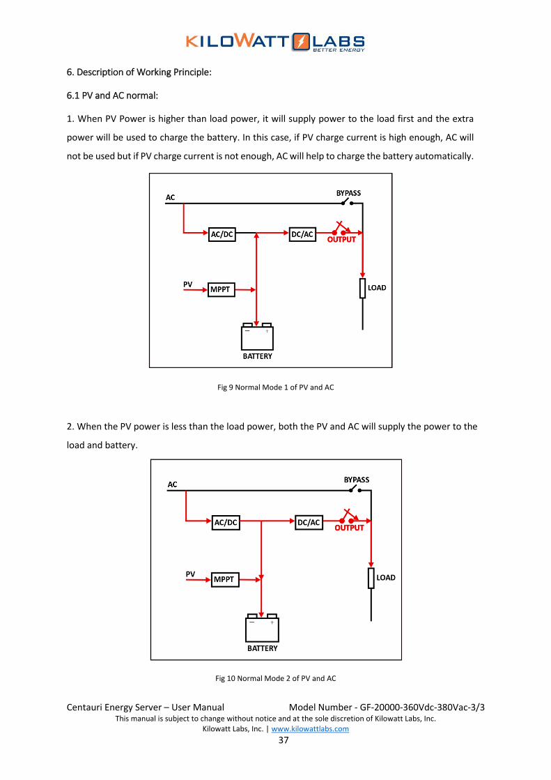
6. Description of Working Principle:
6.1 PV and AC normal:
1. When PV Power is higher than load power, it will supply power to the load first and the extra
power will be used to charge the battery. In this case, if PV charge current is high enough, AC will
not be used but if PV charge current is not enough, AC will help to charge the battery automatically.
Fig 9 Normal Mode 1 of PV and AC
2. When the PV power is less than the load power, both the PV and AC will supply the power to the
load and battery.
Fig 10 Normal Mode 2 of PV and AC

Centauri Energy Server – User Manual Model Number - GF-20000-360Vdc-380Vac-3/3
This manual is subject to change without notice and at the sole discretion of Kilowatt Labs, Inc. Kilowatt Labs, Inc. | www.kilowattlabs.com
38
6.2 AC abnormal or Absent:
1. When the PV power is higher than the load power and AC fails, the PV power will support the
load first and the extra power will be used to charge the battery.
Fig 11 AC Abnormal Mode 1
2. When the PV power is less than the load power and AC fails, the PV together with the battery
will supply the power to the load. When the battery reaches to low cut off voltage, the system
will automatically shut down and the PV will charge the battery. When the battery is fully
charged again or AC runs normally, the system will be ON automatically.
Fig 12 AC Abnormal Mode 2

Centauri Energy Server – User Manual Model Number - GF-20000-360Vdc-380Vac-3/3
This manual is subject to change without notice and at the sole discretion of Kilowatt Labs, Inc. Kilowatt Labs, Inc. | www.kilowattlabs.com
39
6.3 Off-Peak Power Consumption:
1. AC charger OFF: If system has been set AC input OFF or battery low voltage in power supply priority
mode, the rectifier will turn OFF AC charger in set time. PV and rectifier will supply the load first,
and PV extra power will be used to charge the battery.
Fig 13 Off-Peak Setup Mode 1
2. Power Supply Priority: After system set in power supply priority mode, system will turn OFF the
rectifier. Load will be supplied by PV and battery. System will turn to AC charger OFF mode until
battery discharge to DOD point automatically.
Fig 14 Off-Peak Setup Mode 2
Centauri Energy Server – User Manual Model Number - GF-20000-360Vdc-380Vac-3/3
This manual is subject to change without notice and at the sole discretion of Kilowatt Labs, Inc. Kilowatt Labs, Inc. | www.kilowattlabs.com
40
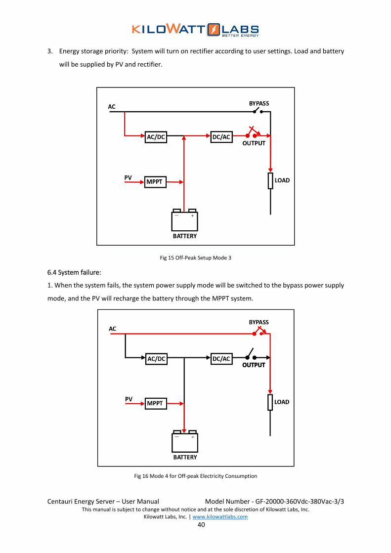
3. Energy storage priority: System will turn on rectifier according to user settings. Load and battery
will be supplied by PV and rectifier.
Fig 15 Off-Peak Setup Mode 3
6.4 System failure:
1. When the system fails, the system power supply mode will be switched to the bypass power supply
mode, and the PV will recharge the battery through the MPPT system.
Fig 16 Mode 4 for Off-peak Electricity Consumption

Centauri Energy Server – User Manual Model Number - GF-20000-360Vdc-380Vac-3/3
This manual is subject to change without notice and at the sole discretion of Kilowatt Labs, Inc. Kilowatt Labs, Inc. | www.kilowattlabs.com
41
7. Maintenance:
7.1 Preventive Maintenance:
The preventive maintenance can make the system reliability and prolong its service life.
The following inspections should be conducted every month:
• Turn OFF the Energy Server (see the operation steps).
• Inspect and make sure that the vent is not blocked.
• Inspect whether there is too much dust on the cover.
• Inspect whether the connecting cables of input, output and the battery are connected firmly and
whether the insulation layer of the cables is in good condition.
• Ensure that the product is not affected with damp.
• Start-up operation (ON/OFF operation for the product).
7.2 Maintenance of Battery:
The sealed battery (lead-acid or lithium-ion) is used for the maintenance of the Energy Server. Its
service life will be shortened dramatically with the preservation and use environment, the discharge
frequency of the battery and the temperature rise. Even if the battery is not used, its performance will
gradually decline, therefore it is recommended that one discharge test (Make sure the battery test
should be executed in the condition of the normal bypass power supply) is conducted every three
months when there is no power outage for a long term. The inspection methods of the battery are
shown as follows (At the end of the use limit of the battery, the battery performance will decline
sharply, therefore be sure to keep in mind the following inspection and maintenance methods):
1. Click the “ ” button on the main interface of the display screen to select the “BAT TEST” option
and then input the “Control Password” (The default password is: 87654321) and click “YES”
button to choose “Battery Self-check” option. At this point, the Energy Server closes the MPPT
and the rectifier; the battery discharges; the “REC” LED on the panel is OFF; the “MPPT” red light
is ON and the “BAT” LED flashes in green.
2. When the Energy Server detects the low voltage alarm of the battery (The depth of discharge can
be adjusted by itself), and the “battery manual maintenance succeeds” information is indicated
on the lower left corner of the LCD panel, it shows that the battery manual maintenance has been
completed. After the completion of the manual maintenance, the Energy Server and the rectifier
are started normally, and the output is continuously switched to the AC inverter output and

Centauri Energy Server – User Manual Model Number - GF-20000-360Vdc-380Vac-3/3
This manual is subject to change without notice and at the sole discretion of Kilowatt Labs, Inc. Kilowatt Labs, Inc. | www.kilowattlabs.com
42
recharges the battery. If necessary, the maintenance staff only needs to select the “CLR TEST”
option in the “Test Order” menu to stop the battery manual maintenance, at this moment, the
inverter will run in the normal working mode.
3. Under the normal use condition, the service life of the battery is about 1~3 years. Under the
conditions of higher temperature, more frequent discharging and deeper depth of discharge, the
service life of the battery reduces to 0.5-1 year.
4. With ageing of the battery, the performance of the battery gets poor. When the battery health
drops down to about 80% of the initial value, the discharge time decreases accordingly. The
battery should be tested every month instead of 3 months.
5. Dustproof treatment:
• Remove the dust and dirt on the battery.
• Check whether all internal wires of the battery are connected firmly or broken, and when
necessary, it must be replaced and repaired.
• Make sure that the batteries and battery terminals are tightened.
7.3 Troubleshooting:
• Operation methods:
→ Click “ ” for check.
7.3.1 Common Troubleshooting:
Alarm Information Explanation Solutions
AC fault
The phase sequence, voltage,
frequency or voltage unbalance
of the rectifier’s input power
supply goes wrong.
Check and make sure that the voltage
and the frequency of the input power
supply is according to the requirement
of the system equipment and whether
the switch is normal.
AC Volt Fail The AC voltage exceeds the
system rated voltage.
Adjust the system input power or wait
for recovery (short fault).
AC Freq Fail The AC frequency exceeds the
system rated value.
Adjust the system input power or wait
for recovery (short fault).

Centauri Energy Server – User Manual Model Number - GF-20000-360Vdc-380Vac-3/3
This manual is subject to change without notice and at the sole discretion of Kilowatt Labs, Inc. Kilowatt Labs, Inc. | www.kilowattlabs.com
43
AC Phase Abnormal The AC phase sequence is not
correctly connected.
Adjust any two phases of the system
input lines.
Bypass Over Load
Protect
When the bypass load is more
than or equal to 150%, the
bypass output will be cut OFF.
When the load shedding is less than
90%, the bypass output will be restored
by pressing “FAULT CLEAR” button.
Inv Over Load
When the inverter load is not
less than 150% and the
overload time is finished, or the
inverter is shut down for
protection.
Output Over Load The load is more than 105%. Get the load shedding to be less than
90%.
REC Fault
After the rectifier is started, the
rectified voltage is lower than
the system set value.
♦ Press “FAULT CLEAR” button for
recovery.
♦ If the fault still exits, please ask the local
authorized technician for service.
Bus Over Volt High-voltage protection of DC
BUS.
BUS Soft Start Fail The soft boot of the rectifier
fails.
Charge Fault The charging current is larger
than the set value.
Bus Low Volt
Shutdown
The voltage of battery
discharge and DC BUS is lower
than minimum set value. The system will not automatically boot
until the AC recovers or the PV is
sufficient and the battery capacity is not
less than 90%. Bat Low Volt
The battery voltage is lower
than the set value.
Bat EOD The battery voltage is lower
than the minimum.
Centauri Energy Server – User Manual Model Number - GF-20000-360Vdc-380Vac-3/3
This manual is subject to change without notice and at the sole discretion of Kilowatt Labs, Inc. Kilowatt Labs, Inc. | www.kilowattlabs.com
44
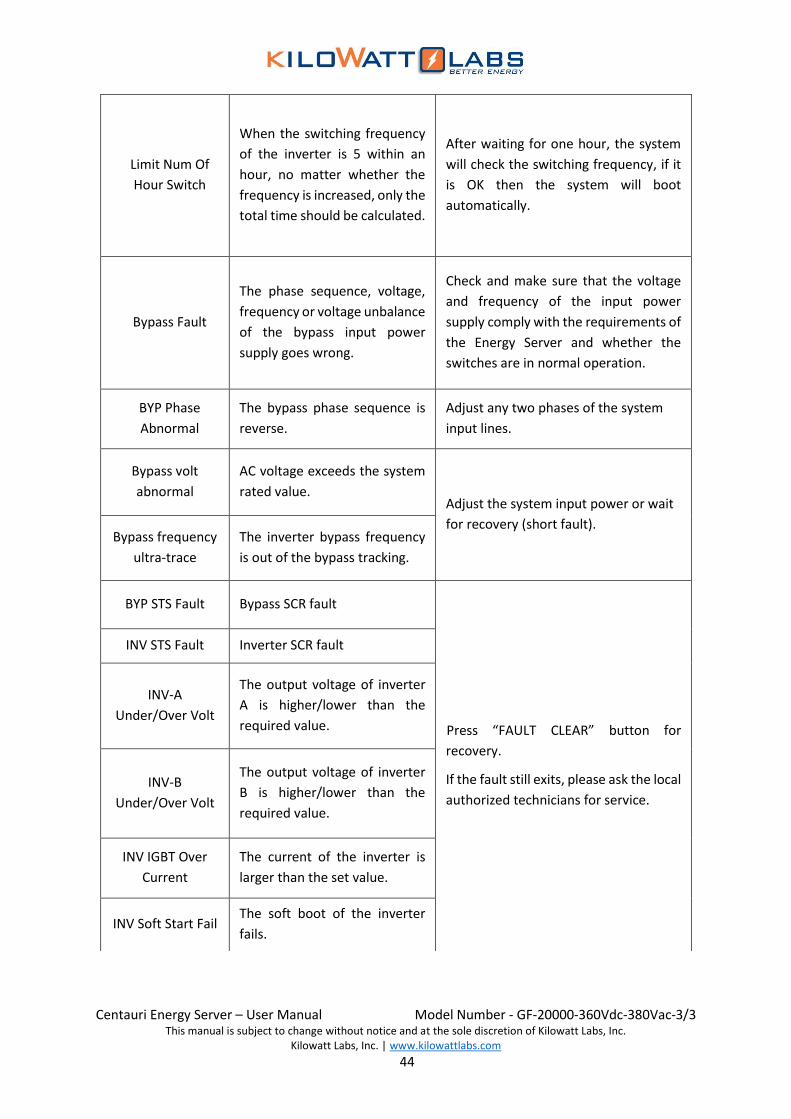
Limit Num Of
Hour Switch
When the switching frequency
of the inverter is 5 within an
hour, no matter whether the
frequency is increased, only the
total time should be calculated.
After waiting for one hour, the system
will check the switching frequency, if it
is OK then the system will boot
automatically.
Bypass Fault
The phase sequence, voltage,
frequency or voltage unbalance
of the bypass input power
supply goes wrong.
Check and make sure that the voltage
and frequency of the input power
supply comply with the requirements of
the Energy Server and whether the
switches are in normal operation.
BYP Phase
Abnormal
The bypass phase sequence is
reverse.
Adjust any two phases of the system
input lines.
Bypass volt
abnormal
AC voltage exceeds the system
rated value. Adjust the system input power or wait
for recovery (short fault). Bypass frequency
ultra-trace
The inverter bypass frequency
is out of the bypass tracking.
BYP STS Fault Bypass SCR fault
Press “FAULT CLEAR” button for
recovery.
If the fault still exits, please ask the local
authorized technicians for service.
INV STS Fault Inverter SCR fault
INV-A
Under/Over Volt
The output voltage of inverter
A is higher/lower than the
required value.
INV-B
Under/Over Volt
The output voltage of inverter
B is higher/lower than the
required value.
INV IGBT Over
Current
The current of the inverter is
larger than the set value.
INV Soft Start Fail The soft boot of the inverter
fails.
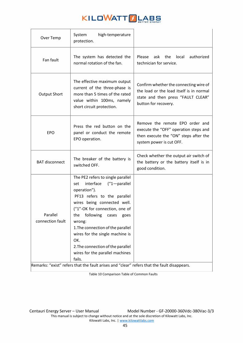
Centauri Energy Server – User Manual Model Number - GF-20000-360Vdc-380Vac-3/3
This manual is subject to change without notice and at the sole discretion of Kilowatt Labs, Inc. Kilowatt Labs, Inc. | www.kilowattlabs.com
45
Over Temp System high-temperature
protection.
Fan fault The system has detected the
normal rotation of the fan.
Please ask the local authorized
technician for service.
Output Short
The effective maximum output
current of the three-phase is
more than 5 times of the rated
value within 100ms, namely
short circuit protection.
Confirm whether the connecting wire of
the load or the load itself is in normal
state and then press “FAULT CLEAR”
button for recovery.
EPO
Press the red button on the
panel or conduct the remote
EPO operation.
Remove the remote EPO order and
execute the “OFF” operation steps and
then execute the “ON” steps after the
system power is cut OFF.
BAT disconnect The breaker of the battery is
switched OFF.
Check whether the output air switch of
the battery or the battery itself is in
good condition.
Parallel
connection fault
The PE2 refers to single parallel
set interface (“1—parallel
operation”).
PF13 refers to the parallel
wires being connected well.
(“1”-OK for connection, one of
the following cases goes
wrong:
1.The connection of the parallel
wires for the single machine is
OK.
2.The connection of the parallel
wires for the parallel machines
fails.
Remarks: “exist” refers that the fault arises and “clear” refers that the fault disappears.
Table 10 Comparison Table of Common Faults

Centauri Energy Server – User Manual Model Number - GF-20000-360Vdc-380Vac-3/3
This manual is subject to change without notice and at the sole discretion of Kilowatt Labs, Inc. Kilowatt Labs, Inc. | www.kilowattlabs.com
46
7.3.2 MPPT Troubleshooting:
Click “ ”to switch the inverter and MPPT information for check.
Alarm Information Explanation Solutions
PV In Reverts The polarity of PV input line of
the MPPT*# module is reversed.
Check and adjust polarity of
PV input line of the MPPT*#
module.
Module Fail MPPT system fault
Please ask the local
authorized technician for
service.
Comm Fail MPPT communication is
interrupted.
Confirm whether screws of
MPPT module are loose.
Please ask the local
authorized technician for
service.
Over Current
The power of PV polar plate is
too high and there is instant
overcurrent.
Check whether the power of
the polar pole confirms to
the system rated value.
Over-Temp
The power of the polar plate is
too high or the local
environment temperature rises
too high or the high-
temperature of the module is
caused by the fan fault.
• Confirm whether the power
of the polar pole and the
environment temperature
exceed the system
requirements. • Please ask the local
authorized technician for
service.
BUS Over Volt The transient loading/unloading
causes the fluctuation of DC BUS.
• The system automatic
adjustment recovers one
minute later.
• If the overvoltage
phenomenon lasts for a long
time, please ask the local
authorized technician for
service.
PV In.C Over.V The transient loading/unloading
causes the fluctuation of DC BUS.
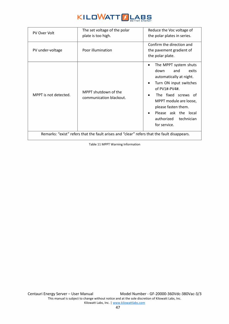
Centauri Energy Server – User Manual Model Number - GF-20000-360Vdc-380Vac-3/3
This manual is subject to change without notice and at the sole discretion of Kilowatt Labs, Inc. Kilowatt Labs, Inc. | www.kilowattlabs.com
47
PV Over Volt The set voltage of the polar
plate is too high.
Reduce the Voc voltage of
the polar plates in series.
PV under-voltage Poor illumination
Confirm the direction and
the pavement gradient of
the polar plate.
MPPT is not detected. MPPT shutdown of the
communication blackout.
• The MPPT system shuts
down and exits
automatically at night.
• Turn ON input switches
of PV1#-PV4#.
• The fixed screws of
MPPT module are loose,
please fasten them.
• Please ask the local
authorized technician
for service.
Remarks: “exist” refers that the fault arises and “clear” refers that the fault disappears.
Table 11 MPPT Warning Information
Related Documents