UM_RF_08_ModBus_Messaging V1.4 www.Beanair.com USER MANUAL Modbus Messaging Implementation Guide

Welcome message from author
This document is posted to help you gain knowledge. Please leave a comment to let me know what you think about it! Share it to your friends and learn new things together.
Transcript

UM_RF_08_ModBus_Messaging V1.4
www.Beanair.com
USER MANUAL Modbus Messaging Implementation Guide

“Rethinking sensing technology” Document version : 1.4
Modbus messaging implementation guide Document Type : User Manual
Please consider the environnement before printing this document.
Page : 1 / 53
DOCUMENT
Document number Version V1.4
External Reference UM_RF_08_ENG_ModBus_Messaging Publication date 14/08/2015
Author Amir Louati
Internal Reference N.A. Project Code N.A.
Document Name ModBus Messaging Implementation Guide
VALIDATION
Function Recipients For Validation
For information
Reader Amir Louati X
Author X
MAILING LIST
Function Recipients For action For Info
Software Architect Mohamed Yosri JOUADI X
Updates
Version Date Author Evolution & Status
V1.0 25/04/2013 Mohamed-Yosri Jaouadi
First version of the document
V1.1 24/02/2015 Amir LOUATI BeanScape Manager
Modbus Function codes
General Measurement conversion formula
V1.2 03/06/015 Maxime Obrazt. Serial Line transmission added
V1.3 14/08/2015 Maxime Obrazt. Example of Typical configuration with QMODBUS Added
V1.4 05/05/2016 Rasha FRIJI
OTAC management from Modbus
Modbus videos
S401-I Module
Conversion formula for INC and HI-INC

“Rethinking sensing technology” Document version : 1.4
Modbus messaging implementation guide Document Type : User Manual
Please consider the environnement before printing this document.
Page : 2 / 53
Disclaimer
The information contained in this document is the proprietary information of Beanair. The contents are confidential and any disclosure to persons other than the officers, employees, agents or subcontractors of the owner or licensee of this document, without the prior written consent of Beanair GmbH, is strictly prohibited. Beanair makes every effort to ensure the quality of the information it makes available. Notwithstanding the foregoing, Beanair does not make any warranty as to the information contained herein, and does not accept any liability for any injury, loss or damage of any kind incurred by use of or reliance upon the information. Beanair disclaims any and all responsibility for the application of the devices characterized in this document, and notes that the application of the device must comply with the safety standards of the applicable country, and where applicable, with the relevant wiring rules. Beanair reserves the right to make modifications, additions and deletions to this document due to typographical errors, inaccurate information, or improvements to programs and/or equipment at any time and without notice. Such changes will, nevertheless be incorporated into new editions of this document. Copyright: Transmittal, reproduction, dissemination and/or editing of this document as well as utilization of its contents and communication thereof to others without express authorization are prohibited. Offenders will be held liable for payment of damages. All rights are reserved.
Copyright © Beanair GmBh 2015

“Rethinking sensing technology” Document version : 1.4
Modbus messaging implementation guide Document Type : User Manual
Please consider the environnement before printing this document.
Page : 3 / 53
1. TECHNICAL SUPPORT ............................................................................................................................. 5
2. VISUAL SYMBOLS DEFINITION ............................................................................................................... 6
3. ACRONYMS AND ABBREVIATIONS ........................................................................................................ 7
4. RELATED DOCUMENTS ........................................................................................................................... 8
4.1 Application Notes ............................................................................................................................... 8
4.2 Technical Notes .................................................................................................................................. 9
5. SCOPE OF THIS DOCUMENT ................................................................................................................ 10
6. MODBUS COMMUNICATION .................................................................................................................. 11
7. MODBUS MASTER / SLAVE PROTOCOL PRINCIPLE .......................................................................... 13
8. SERIAL LINE TRANSMISSION................................................................................................................ 15
8.1 RTU – Transmission mode ............................................................................................................... 15
8.1.1 Data format ............................................................................................................................. 15
8.1.2 How characters are transmitted serially ................................................................................. 16
8.1.3 CRC Checking ........................................................................................................................ 17
8.1 ASCII – Transmission mode ............................................................................................................. 17
8.1.1 Data format ............................................................................................................................. 18
8.1.2 How Characters are transmitted serially ................................................................................ 18
8.2 LRC Checking .................................................................................................................................. 19
9. MODBUS CONFIGURATION FROM THE BEANSCAPE® SOFTWARE ............................................... 20
9.1 Start/Stop Modbus Slave .................................................................................................................. 20
9.1.1 Start Modbus Slave ................................................................................................................ 20
9.1.2 Stop Modbus Slave ................................................................................................................ 21
9.2 Configure Modbus Slave .................................................................................................................. 21
9.2.1 Modbus Interface .................................................................................................................... 22
9.2.2 Device addressing mode ........................................................................................................ 22
Contents

“Rethinking sensing technology” Document version : 1.4
Modbus messaging implementation guide Document Type : User Manual
Please consider the environnement before printing this document.
Page : 4 / 53
9.2.3 Date Field Option .................................................................................................................... 22
9.2.4 Slave adresse ......................................................................................................................... 22
9.2.5 ModBus RTU/ASCII (RS232/RS485) ..................................................................................... 22
9.2.6 Termination (RS485) .............................................................................................................. 23
9.3 Modbus Assistant ............................................................................................................................. 23
9.4 Initialise Modbus ............................................................................................................................... 24
9.5 MacId Table Configuration ............................................................................................................... 25
10. MOSBUS FUNCTION CODES IMPLEMENTED ON THE BEANGATEWAY® ....................................... 27
10.1 Read Input Register (04) .................................................................................................................. 27
10.1.1 Registered Device Count ........................................................................................................ 27
10.1.2 Device Sensor Information ..................................................................................................... 27
10.1.3 Device Measurement Information ........................................................................................... 28
10.1.4 Read Data ............................................................................................................................... 29
10.1.5 Data Ready to be Read .......................................................................................................... 30
10.2 Read Single Register (03) ................................................................................................................ 31
10.3 Write Single Register (06) ................................................................................................................ 31
10.4 Read Multiple Registers (16) ............................................................................................................ 31
10.5 Read/Write Multiple Registers (25) .................................................................................................. 31
10.6 Report Slave ID (17) ......................................................................................................................... 32
11. MODBUS EXCEPTION CODES IMPLEMENTED ON THE BEANGATEWAY® ..................................... 33
12. MEASUREMENT CONVERSION FORMULA .......................................................................................... 35
12.1 Conversion Formula ......................................................................................................................... 35
12.2 Offset and Ratio................................................................................................................................ 35
12.3 Conversion formula for INC/HI-INC .................................................................................................. 37
13. OTAC MANAGEMENT FROM MODBUS ................................................................................................ 39
13.1 Data acquisition mode ...................................................................................................................... 40
13.2 Power supply .................................................................................................................................... 42
13.3 Example ............................................................................................................................................ 43
14. S401-I MODULE ....................................................................................................................................... 44
14.1 Wiring code (RS485 Master) ............................................................................................................ 45
14.2 Add a new BeanDevice .................................................................................................................... 47
14.3 s401-I Module Display ...................................................................................................................... 49
15. APPENDICES ........................................................................................................................................... 51
15.1 Appendix 1: Testing with QModBus ................................................................................................. 51
13.2 Appendix 1: Example videos ............................................................................................................. 52

“Rethinking sensing technology” Document version : 1.4
Modbus messaging implementation guide Document Type : User Manual
Please consider the environnement before printing this document.
Page : 5 / 53
1. TECHNICAL SUPPORT
For general contact, technical support, to report documentation errors and to order manuals, contact Beanair Technical Support Center (BTSC) at: [email protected] For detailed information about where you can buy the Beanair equipment/software or for recommendations on accessories and components visit: www.Beanair.com To register for product news and announcements or for product questions contact Beanair’s Technical Support Center (BTSC). Our aim is to make this user manual as helpful as possible. Please keep us informed of your comments and suggestions for improvements. Beanair appreciates feedback from the users.

“Rethinking sensing technology” Document version : 1.4
Modbus messaging implementation guide Document Type : User Manual
Please consider the environnement before printing this document.
Page : 6 / 53
2. VISUAL SYMBOLS DEFINITION
Symbols Definition
Caution or Warning – Alerts the user with important information about Beanair wireless sensor networks (WSN), if this information is not followed, the equipment /software may fail or malfunction.
Danger – This information MUST be followed if not you may damage the equipment permanently or bodily injury may occur.
Tip or Information – Provides advice and suggestions that may be useful when installing Beanair Wireless Sensor Networks.

“Rethinking sensing technology” Document version : 1.4
Modbus messaging implementation guide Document Type : User Manual
Please consider the environnement before printing this document.
Page : 7 / 53
3. ACRONYMS AND ABBREVIATIONS
ADU Application Data Unit
AES Advanced Encryption Standard
CCA Clear Channel Assessment
CSMA/CA Carrier Sense Multiple Access/Collision Avoidance
GTS Guaranteed Time-Slot
kSps Kilo samples per second
LLC Logical Link Control
LQI Link quality indicator
LDCDA Low duty cycle data acquisition
MAC Media Access Control
MB ModBus
MBAP ModBus Application Protocol
PAN Personal Area Network
PDU Protocol Data Unit
PER Packet error rate
PLC Programmable Logic Controller
MSL Maximum Segment Lifetime
RF Radio Frequency
SD Secure Digital
SSD Smart shock detection
WSN Wireless sensor Network

“Rethinking sensing technology” Document version : 1.4
Modbus messaging implementation guide Document Type : User Manual
Please consider the environnement before printing this document.
Page : 8 / 53
4. RELATED DOCUMENTS
In addition to this User manual, please consult the application notes & technical notes mentioned below:
4.1 APPLICATION NOTES
Document name (Click on the weblink)
Related product Description
AN_RF_007 :“ Beanair_WSN_Deployment“
All BeanAir products Wireless sensor networks deployment guidelines
AN_RF_006 – „How to extend your wireless range“
All BeanAir products A guideline very useful for extending your wireless range
AN_RF_005 – BeanGateway ® & Data Terminal Equipment Interface
BeanGateway ® DTE interface Architecture on the BeanGateway ®
AN_RF_003 - “IEEE 802.15.4 2.4 GHz Vs 868 MHz”
All BeanAir products Comparison between 868 MHz frequency band and a 2.4 GHz frequency band.
AN_RF_002 – “Structural Health monitoring on bridges”
All BeanAir products
The aim of this document is to overview Beanair® products suited for bridge monitoring, their deployment, as well as their capacity and limits by overviewing various Data acquisition modes available on each BeanDevice®.

“Rethinking sensing technology” Document version : 1.4
Modbus messaging implementation guide Document Type : User Manual
Please consider the environnement before printing this document.
Page : 9 / 53
4.2 TECHNICAL NOTES
Document name (Click on the weblink)
Related product Description
TN_RF_013 – « OPC configuration » BeanScape® Premium+ The aim of this document is to help deploying the OPC DA and all associated services.
TN_RF_012– « BeanDevice® battery life in streaming mode »
All the products
The aim of this document is to describe the autonomy performance of the BeanDevice® SmartSensor® and ProcessSensor® product line in streaming packet mode.
TN_RF_011 – « Coexistence of Beanair WSN at 2.4GHz »
All the products
This document aims to highlight the issues affecting co-existence of Beanair WSN (IEEE 802.15.4) in the presence of interference.
TN_RF_010 – « BeanDevice® Power Management »
All the BeanDevice® This technical note describes the sleeping & active power mode on the BeanDevice®.
TN_RF_009 – « BeanGateway ® management on LAN infrastructure »
BeanGateway ® BeanGateway ® integration on a LAN infrastructure
TN_RF_008 – “Data acquisition modes available on the BeanDevice®”
All the BeanDevice® Data acquisition modes available on the BeanDevice®
TN_RF_007 – “BeanDevice® DataLogger User Guide ”
All the BeanDevice® This document presents the DataLogger feature on the BeanDevice®
TN_RF_006 – “WSN Association process”
All the BeanDevice®
Description of the BeanDevice® network association
TN_RF_005 – “Pulse counter & binary Data acquisition on the BeanDevice® SUN-BN”
BeanDevice® SUN-BN
This document presents Pulse counter (ex: energy metering application) and binary Data acquisition features on the BeanDevice® SUN-BN.
RF_TN_003- “Aggregation capacity of wireless sensor networks”
All the products Network capacity characterization of Beanair Wireless Sensor Networks
RF_TN_002 V1.0 - Current consumption in active & sleeping mode
BeanDevice® Current consumption estimation of the BeanDevice in active and sleeping mode
RF_TN_001 V1.0- Wireless range benchmarking
BeanDevice® Wireless range benchmarking of the BeanDevice®

“Rethinking sensing technology” Document version : 1.4
Modbus messaging implementation guide Document Type : User Manual
Please consider the environnement before printing this document.
Page : 10 / 53
5. SCOPE OF THIS DOCUMENT
MODBUS is an application-layer messaging protocol, positioned at level 7 of the OSI model. It provides client/server communication between devices connected on different types of buses or networks.
The de facto industrial serial standard since 1979, MODBUS continues to enable millions of automation devices to communicate. Today, support for the simple and elegant structure of MODBUS continues to grow. The Internet community can access MODBUS at a reserved system port 502 on the TCP/IP stack.
MODBUS is a request/reply protocol and offers services specified by function codes. MODBUS function codes are elements of MODBUS request/reply PDUs. This protocol specification document describes the function codes used within the framework of MODBUS transactions.
ModBus is not compatible with the streaming packet mode

“Rethinking sensing technology” Document version : 1.4
Modbus messaging implementation guide Document Type : User Manual
Please consider the environnement before printing this document.
Page : 11 / 53
6. MODBUS COMMUNICATION
MODBUS is an application layer messaging protocol for client/server communication between devices connected on different types of buses or networks. The ModBus Slave is implemented on the Beangateway®, the following ModBus versions are available on the BeanGateway®: ModBus IP: TCP/IP over Ethernet Asynchronous serial transmission over a variety of media (wire: RS485/RS232)
Figure 1: ModBus slave operation
“Rethinking sensing technology” Document version : 1.4
Modbus messaging implementation guide Document Type : User Manual
Please consider the environnement before printing this document.
Page : 12 / 53
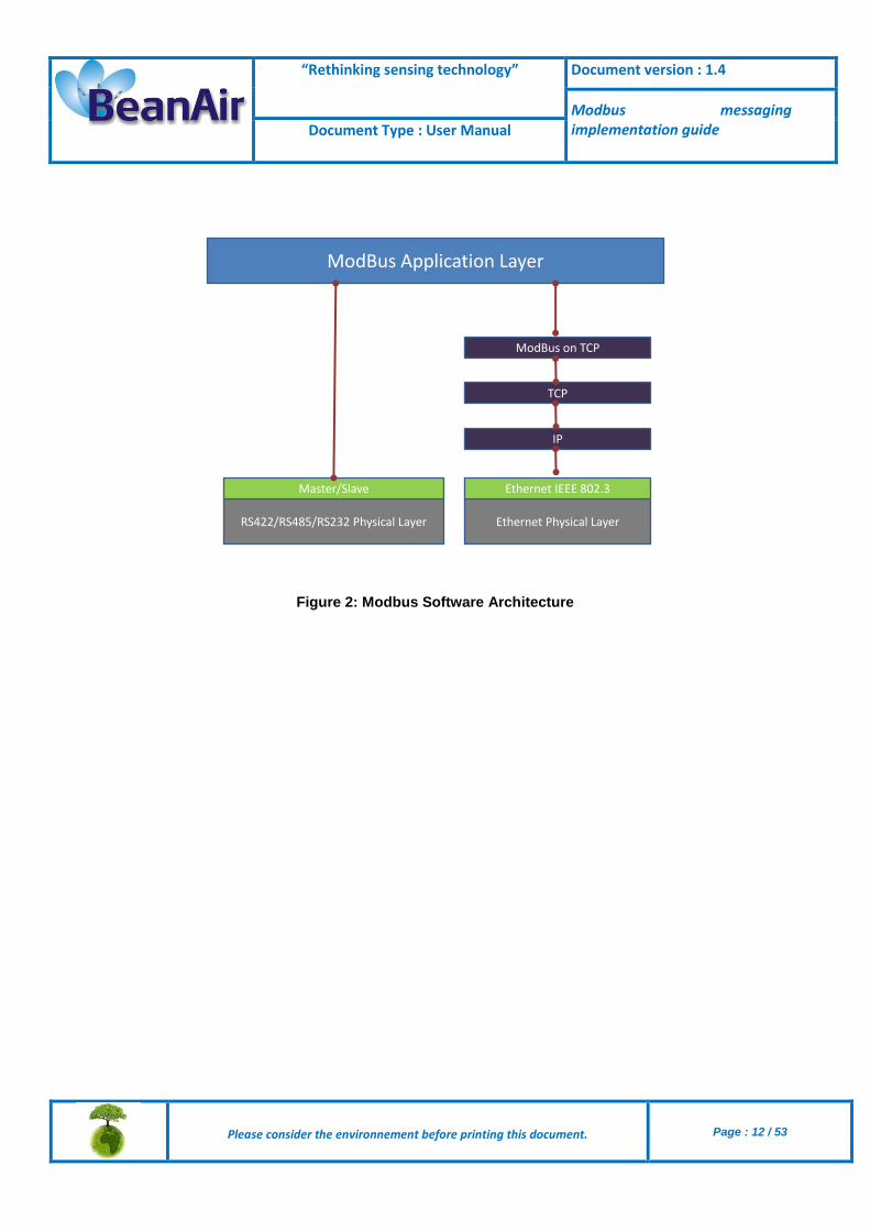
Figure 2: Modbus Software Architecture
ModBus Application Layer
Ethernet Physical LayerRS422/RS485/RS232 Physical Layer
Master/Slave Ethernet IEEE 802.3
IP
TCP
ModBus on TCP

“Rethinking sensing technology” Document version : 1.4
Modbus messaging implementation guide Document Type : User Manual
Please consider the environnement before printing this document.
Page : 13 / 53
7. MODBUS MASTER / SLAVE PROTOCOL PRINCIPLE
The Modbus Serial Line protocol is a Master-Slaves protocol. Only one master (at the same time) is connected to the bus, and one or several (247 maximum number) slave nodes are also connected to the same serial bus. A Modbus communication is always initiated by the master. The slave nodes will never transmit data without receiving a request from the master node. The slave nodes will never communicate with each other. The master node initiates only one Modbus transaction at the same time. The master node issues a Modbus request to the slave nodes in two modes: In unicast mode, the master addresses an individual slave. After receiving and processing
the request, the slave returns a message (a 'reply') to the master. In that mode, a MODBUS transaction consists of 2 messages: a request from the master, and a reply from the slave. Each slave must have a unique address (from 1 to 247) so that it can be addressed independently from other nodes.
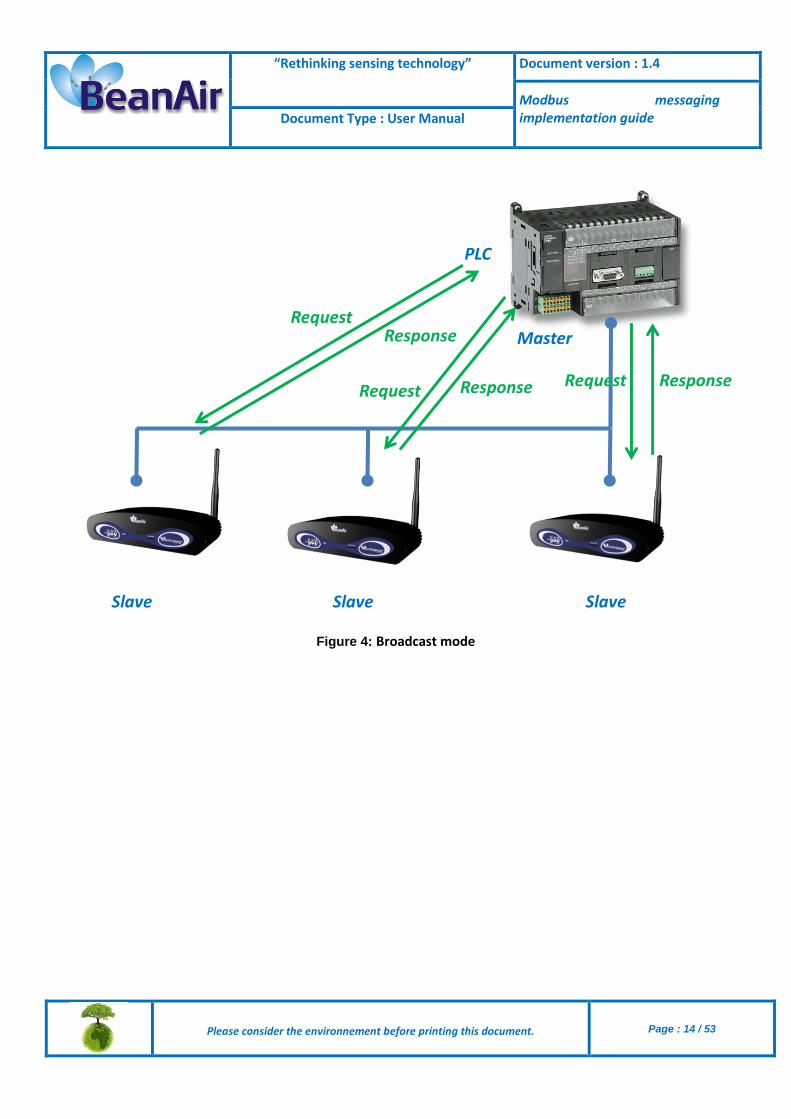
In broadcast mode, the master can send a request to all slaves. No response is returned to broadcast requests sent by the master. The broadcast requests are necessarily writing commands. All devices must accept the broadcast for writing function. The address 0 is reserved to identify a broadcast exchange.
Figure 3 : Unicast mode
PLC
Master
Slave Slave Slave
Request
Response
“Rethinking sensing technology” Document version : 1.4
Modbus messaging implementation guide Document Type : User Manual
Please consider the environnement before printing this document.
Page : 14 / 53
Figure 4: Broadcast mode
PLC
Master
Slave Slave Slave
RequestResponse
RequestResponse ResponseRequest

“Rethinking sensing technology” Document version : 1.4
Modbus messaging implementation guide Document Type : User Manual
Please consider the environnement before printing this document.
Page : 15 / 53
8. SERIAL LINE TRANSMISSION
Two different serial transmission modes are defined: the RTU mode and the ASCII mode. It defines the bit contents of message fields transmitted serially on the line. It determines how information is packed into the message fields and decoded. Although the ASCII mode is required in some specific applications, interoperability between MODBUS devices can be reached only if each device has the same transmission mode. The BeanGateway® should be set up by the users to the desired transmission mode, RTU or ASCII. Default setup on the BeanGateway® is the RTU mode.
The transmission mode (and serial port parameters) must be the same for all devices on a MODBUS Serial Line.
8.1 RTU – TRANSMISSION MODE
When devices communicate on a MODBUS serial line using the RTU (Remote Terminal Unit) mode, each 8–bit byte in a message contains two 4–bit hexadecimal characters. The main advantage of this mode is that its greater character density allows better data throughput than ASCII mode for the same baud rate. Each message must be transmitted in a continuous stream of characters.
8.1.1 Data format
The format (11 bits) for each byte in RTU mode is:
Coding System 8–bit binary
Bits per Byte
1 start bit 8 data bits, least significant bit sent first 1 bit for parity completion 1 stop bit
In order to ensure a maximum compatibility with other products, the BeanGateway® can manage Even Parity (required), odd parity and no parity. The default parity mode is even parity.
The use of no parity requires 2 stop bits.
“Rethinking sensing technology” Document version : 1.4
Modbus messaging implementation guide Document Type : User Manual
Please consider the environnement before printing this document.
Page : 16 / 53
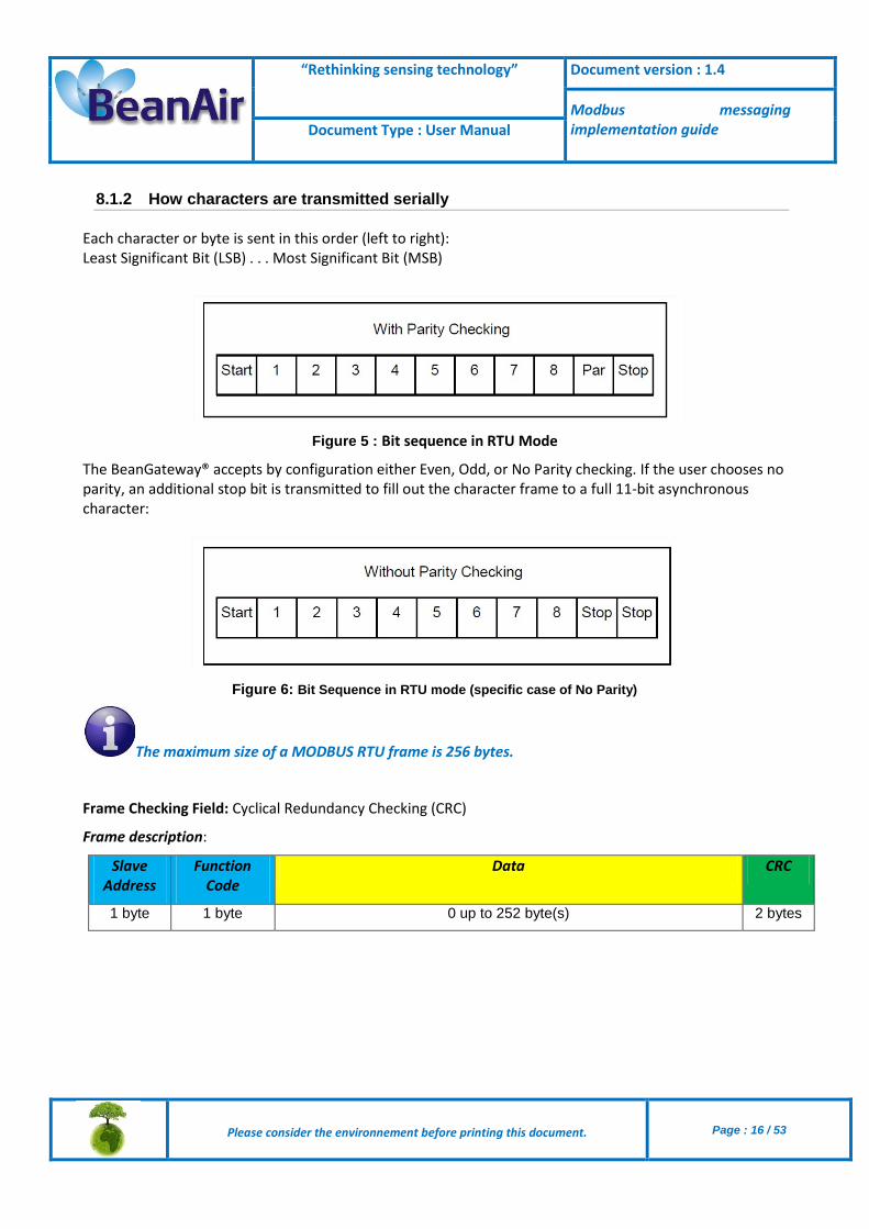
8.1.2 How characters are transmitted serially
Each character or byte is sent in this order (left to right): Least Significant Bit (LSB) . . . Most Significant Bit (MSB)
Figure 5 : Bit sequence in RTU Mode
The BeanGateway® accepts by configuration either Even, Odd, or No Parity checking. If the user chooses no parity, an additional stop bit is transmitted to fill out the character frame to a full 11-bit asynchronous character:
Figure 6: Bit Sequence in RTU mode (specific case of No Parity)
The maximum size of a MODBUS RTU frame is 256 bytes.
Frame Checking Field: Cyclical Redundancy Checking (CRC)
Frame description:
Slave Address
Function Code
Data CRC
1 byte 1 byte 0 up to 252 byte(s) 2 bytes

“Rethinking sensing technology” Document version : 1.4
Modbus messaging implementation guide Document Type : User Manual
Please consider the environnement before printing this document.
Page : 17 / 53
8.1.3 CRC Checking
The RTU mode includes an error–checking field that is based on a Cyclical Redundancy Checking (CRC) method performed on the message contents. The CRC field checks the contents of the entire message. It is applied regardless of any parity checking method used for the individual characters of the message. The CRC field contains a 16–bit value implemented as two 8–bit bytes. The CRC field is appended to the message as the last field in the message. When this is done, the low–order byte of the field is appended first, followed by the high–order byte. The CRC high–order byte is the last byte to be sent in the message. The CRC value is calculated by the sending device, which appends the CRC to the message. The receiving device recalculates a CRC during receipt of the message, and compares the calculated value to the actual value it received in the CRC field. If the two values are not equal, an error results. The CRC calculation is started by first pre-loading a 16–bit register to all 1’s. Then a process begins of applying successive 8–bit bytes of the message to the current contents of the register. Only the eight bits of data in each character are used for generating the CRC. Start and stop bits and the parity bit, do not apply to the CRC.
8.1 ASCII – TRANSMISSION MODE
When devices are setup to communicate on a MODBUS serial line using ASCII (American Standard Code for Information Interchange) mode, each 8–bit byte in a message is sent as two ASCII characters. This mode is used when the physical communication link or the capabilities of the device does not allow the conformance with RTU mode requirements regarding timers management.
This mode is less efficient than RTU since each byte needs two characters. Example: The byte 0x5B is encoded as two characters: 0x35 and 0x42 (0x35 ="5", and 0x42 ="B" in ASCII).

“Rethinking sensing technology” Document version : 1.4
Modbus messaging implementation guide Document Type : User Manual
Please consider the environnement before printing this document.
Page : 18 / 53
8.1.1 Data format
The format (10 bits) for each byte in ASCII mode is:
Coding System Hexadecimal, ASCII characters 0–9, A–F
One hexadecimal character contains 4-bits of data within each ASCII character of the message
Bits per Byte
1 start bit 7 data bits, least significant bit sent first 1 bit for parity completion; 1 stop bit
In order to ensure a maximum compatibility with other products, the BeanGateway® can manage Even Parity (required), odd parity and no parity. The default parity mode is even parity.
The use of no parity requires 2 stop bits.
8.1.2 How Characters are transmitted serially
Each character or byte is sent in this order (left to right): Least Significant Bit (LSB) . . . Most Significant Bit (MSB)
Figure 7 : Bit Sequence in ASCII mode

“Rethinking sensing technology” Document version : 1.4
Modbus messaging implementation guide Document Type : User Manual
Please consider the environnement before printing this document.
Page : 19 / 53
Figure 8 : Bit Sequence in ASCII mode (specific case of No Parity)
Frame Checking Field: Longitudinal Redundancy Checking (LRC)
8.2 LRC CHECKING
In ASCII mode, messages include an error–checking field that is based on a Longitudinal Redundancy Checking (LRC) calculation that is performed on the message contents, exclusive of the beginning ‘colon’ and terminating CRLF pair characters. It is applied regardless of any parity checking method used for the individual characters of the message. The LRC field is one byte, containing an 8–bit binary value. The LRC value is calculated by the device that emits, which appends the LRC to the message. The device that receives calculates an LRC during receipt of the message, and compares the calculated value to the actual value it received in the LRC field. If the two values are not equal, an error results. The LRC is calculated by adding together successive 8–bit bytes of the message, discarding any carries, and then two’s complementing the result. It is performed on the bytes of the message, before the encoding of each byte in the two ASCII characters corresponding to the hexadecimal representation of each nibble. The computation does not include the 'colon' character that begins the message, and does not include the CRLF pair at the end of the message. The resulting LRC is ASCII encoded into two bytes and placed at the end of the ASCII mode frame before the CRLF.

“Rethinking sensing technology” Document version : 1.4
Modbus messaging implementation guide Document Type : User Manual
Please consider the environnement before printing this document.
Page : 20 / 53
9. MODBUS CONFIGURATION FROM THE BEANSCAPE® SOFTWARE
9.1 START/STOP MODBUS SLAVE
9.1.1 Start Modbus Slave
Click on “START” button to start ModBus communication.
Figure 9: Start Modbus slave
“Rethinking sensing technology” Document version : 1.4
Modbus messaging implementation guide Document Type : User Manual
Please consider the environnement before printing this document.
Page : 21 / 53
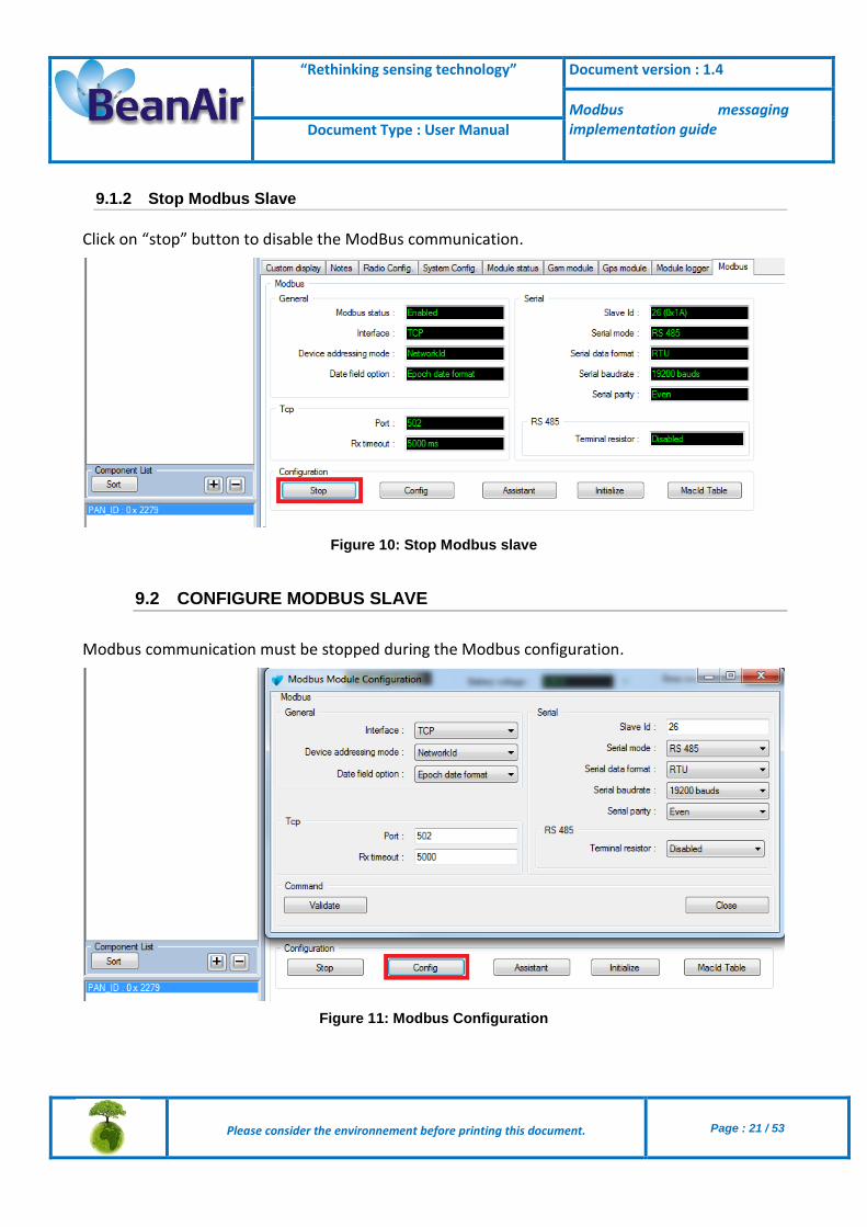
9.1.2 Stop Modbus Slave
Click on “stop” button to disable the ModBus communication.
Figure 10: Stop Modbus slave
9.2 CONFIGURE MODBUS SLAVE
Modbus communication must be stopped during the Modbus configuration.
Figure 11: Modbus Configuration

“Rethinking sensing technology” Document version : 1.4
Modbus messaging implementation guide Document Type : User Manual
Please consider the environnement before printing this document.
Page : 22 / 53
9.2.1 Modbus Interface
Several versions of our BeanGateway Modbus are available:
BeanGateway Modbus IP - Indoor/Outdoor casing BeanGateway ModBus ASCII/RTU over RS232 layer - Indoor casing BeanGateway Modbus IP & Modbus ASCII/RTU over RS485 layer - Indoor/Outdoor casing BeanGateway Modbus IP & Modbus ASCII/RTU over RS485 & RS232 layers - Indoor casing
9.2.2 Device addressing mode
Device’s measurement and information Register address are based on:
Devise Network ID.
MacID table index.
9.2.3 Date Field Option
Several Timestamp options are available:
Epoch data format
Long date format
None
9.2.4 Slave adresse
Range from 1 to 247
9.2.5 ModBus RTU/ASCII (RS232/RS485)
Six options are available for serial baud rate:
4800 Bauds.
9600 Bauds.
19200 Bauds.
38400 Bauds.
57600 Bauds.
115200 Bauds.

“Rethinking sensing technology” Document version : 1.4
Modbus messaging implementation guide Document Type : User Manual
Please consider the environnement before printing this document.
Page : 23 / 53
Parity
The user can select three different type of Parity for serial ModBus:
Even
Odd
None
Stop bit:
For Even and Odd parity option the serial communication use one stop bit.
For none parity option the serial communication use tow stop bit.
9.2.6 Termination (RS485)
An internal 120Ω resistor can be enabled or disabled
9.3 MODBUS ASSISTANT
The Assistant table is used to compute the address and length of data related to devices. In addition, the assistance compute the offset and ratio that must be used to find the physically value of the acquisition.
Figure 12: BeanGateway Modbus Register Assistance

“Rethinking sensing technology” Document version : 1.4
Modbus messaging implementation guide Document Type : User Manual
Please consider the environnement before printing this document.
Page : 24 / 53
The Assistant window provide help to compute Register address in order to have further information about devices.
Figure 13: BeanGateway Other Registers
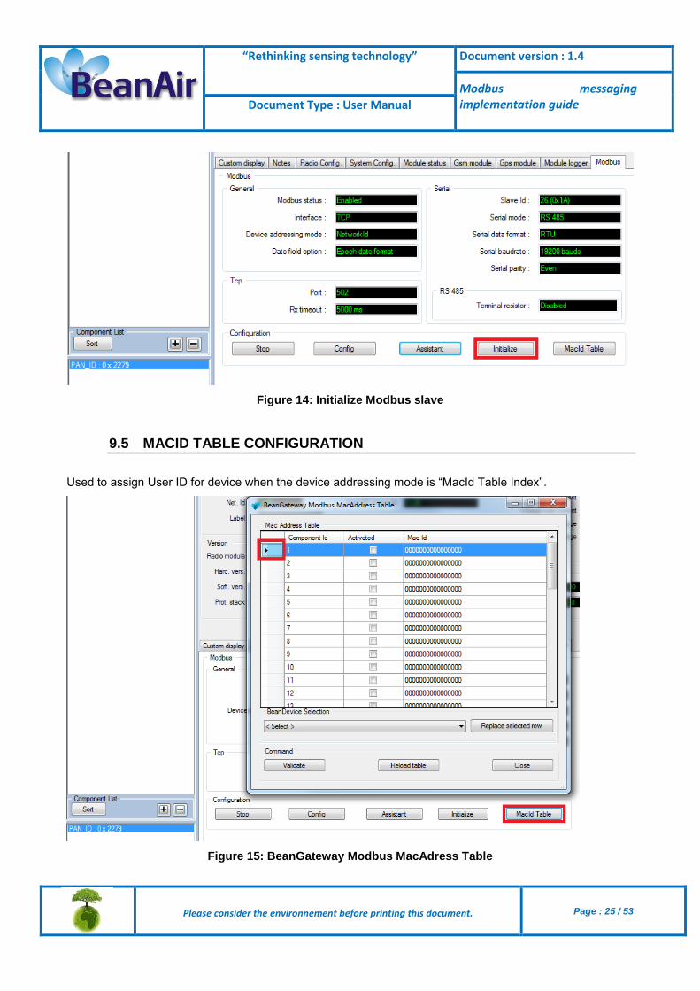
9.4 INITIALISE MODBUS
This function restores factory settings and delete MACID table.
“Rethinking sensing technology” Document version : 1.4
Modbus messaging implementation guide Document Type : User Manual
Please consider the environnement before printing this document.
Page : 25 / 53
Figure 14: Initialize Modbus slave
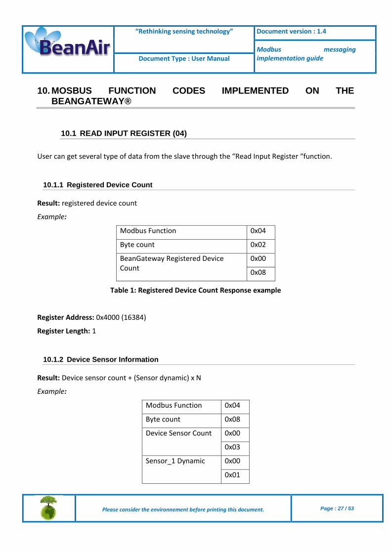
9.5 MACID TABLE CONFIGURATION
Used to assign User ID for device when the device addressing mode is “MacId Table Index”.
Figure 15: BeanGateway Modbus MacAdress Table

“Rethinking sensing technology” Document version : 1.4
Modbus messaging implementation guide Document Type : User Manual
Please consider the environnement before printing this document.
Page : 26 / 53
To fill out this table, the user should:
Select a row from the table (can be empty are filled by another device).
Chose a device from the BeanDevice® selection list and press on “Replace selection row” button.
Added devices should be activated by selcting the “Activated” option.
Press on “Validate” button after ending.
Note: Modbus Slave should be stopped to accept new MacId Table configuration.
Figure 16: Filling MacAdress table
“Rethinking sensing technology” Document version : 1.4
Modbus messaging implementation guide Document Type : User Manual
Please consider the environnement before printing this document.
Page : 27 / 53
10. MOSBUS FUNCTION CODES IMPLEMENTED ON THE BEANGATEWAY®
10.1 READ INPUT REGISTER (04)
User can get several type of data from the slave through the “Read Input Register “function.
10.1.1 Registered Device Count
Result: registered device count
Example:
Modbus Function 0x04
Byte count 0x02
BeanGateway Registered Device Count
0x00
0x08
Table 1: Registered Device Count Response example
Register Address: 0x4000 (16384)
Register Length: 1
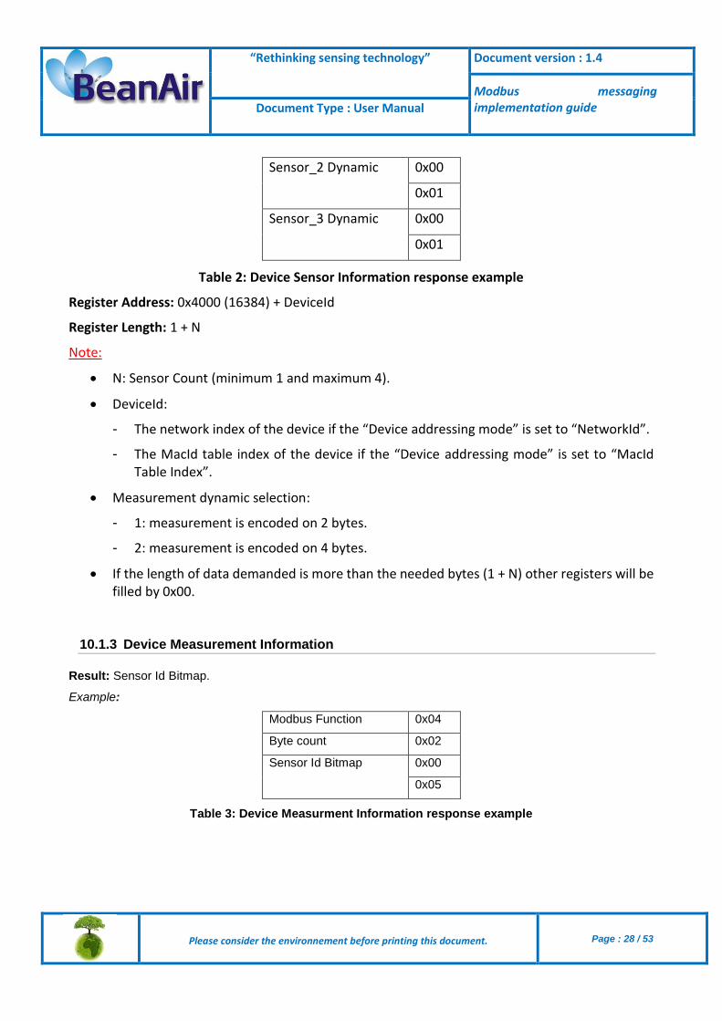
10.1.2 Device Sensor Information
Result: Device sensor count + (Sensor dynamic) x N
Example:
Modbus Function 0x04
Byte count 0x08
Device Sensor Count 0x00
0x03
Sensor_1 Dynamic 0x00
0x01
“Rethinking sensing technology” Document version : 1.4
Modbus messaging implementation guide Document Type : User Manual
Please consider the environnement before printing this document.
Page : 28 / 53
Sensor_2 Dynamic 0x00
0x01
Sensor_3 Dynamic 0x00
0x01
Table 2: Device Sensor Information response example
Register Address: 0x4000 (16384) + DeviceId
Register Length: 1 + N
Note:
N: Sensor Count (minimum 1 and maximum 4).
DeviceId:
- The network index of the device if the “Device addressing mode” is set to “NetworkId”.
- The MacId table index of the device if the “Device addressing mode” is set to “MacId Table Index”.
Measurement dynamic selection:
- 1: measurement is encoded on 2 bytes.
- 2: measurement is encoded on 4 bytes.
If the length of data demanded is more than the needed bytes (1 + N) other registers will be filled by 0x00.
10.1.3 Device Measurement Information
Result: Sensor Id Bitmap.
Example:
Modbus Function 0x04
Byte count 0x02
Sensor Id Bitmap 0x00
0x05
Table 3: Device Measurment Information response example

“Rethinking sensing technology” Document version : 1.4
Modbus messaging implementation guide Document Type : User Manual
Please consider the environnement before printing this document.
Page : 29 / 53
Note: 0x05 = 0b0000 0101(Binary format) the slave has data acquisition related to the sensor_1 and
sensor_3.
Register Address: 0x4000 (16384) + DeviceId x 256
Register Length: 1
Note:
DeviceId:
The network index of the device if the “Device addressing mode” is set to “NetworkId”.
The MacId table index of the device if the “Device addressing mode” is set to “MacId Table Index”.
10.1.4 Read Data
Result: Date of Data Acquisition + (Sensor Data Acquisition) x N
Example:
Modbus Function 0x04
Byte count 0x08
Data Date (Epoch config)
0x89
0x54
0xF4
0x89
Sensor_2 Data 0xFF
0xB1
Sensor_3 Data 0x1C
0xDE
Table 4 : Read Data response example
Register Address: 0x4000 (16384) + DeviceId x 256 + Device Request Sensor Bitmap
Example: Reading Data from Sensor_2 and Sensor_3 from sensor 5 and date is configured with “Epoch” Timestamp
Sensor Bitmap = 0b0000 0110 (Binary format) = 0x06 (Hex format) = 6
Register Address: 0x4506
Register Length: 4 = 2 (for Date format) + 1(for sensor_2 data) + 1(for sensor_3 data)
Register Length: T + N OR T + 2 x N Depend on the Sensors Dynamic.
Note:
N: Sensor Count (minimum 1 and maximum 4).

“Rethinking sensing technology” Document version : 1.4
Modbus messaging implementation guide Document Type : User Manual
Please consider the environnement before printing this document.
Page : 30 / 53
T: Date length, can be:
0 if “Date Field Option” is set to “No date field”.
2 if “Date Field Option” is set to “Epoch date format”.
6 if “Date Field Option” is set to “Long date format”.
DeviceId:
- The network index of the device if the “Device addressing mode” is set to “NetworkId”.
- The MacId table index of the device if the “Device addressing mode” is set to “MacId Table Index”.
The device request sensor Bitmap must composed by validated sensor Bitmap witch can be determinate using “Device Measurement Information” command.
If the length of data demanded is more than the needed bytes [(T + N) or (T + 2 x N)] other registers will be filled by 0x00.
The Register Address and Register Length can be determinate by using “Data Ready to be Read“ function.
10.1.5 Data Ready to be Read
Result: Ready device count + (Data Register Address + Data Register Length) x N
Example:
Modbus Function 0x04
Byte count 0x0A
Device Sensor Count 0x00
0x02
Device_1 Data Register Address
0x42
0x01
Device_1 Data Register Length
0x00
0x03
Device_2 Data Register Address
0x4B
0x05
Device_2 Data Register Length
0x00
0x04

“Rethinking sensing technology” Document version : 1.4
Modbus messaging implementation guide Document Type : User Manual
Please consider the environnement before printing this document.
Page : 31 / 53
Table 5: Data Ready to be Read response example
Register Address: 0x0000 (0)
Register Length: 1 + 2 x N
Note:
N: Count of Data Ready to be read (minimum 0 and maximum 40).
If the length of data demanded is more than the needed bytes (1 + 2 x N) other registers will be filled by 0x00.
If the data had been read through “Read Data” sub function it will be discarded from the “Data Ready to be Read” sub function response unless a new data acquisition is received and had not yet been read.
10.2 READ SINGLE REGISTER (03)
Ten volatile registers are available for the user initialized by 0.
Register address zone: [999 … 1009].
10.3 WRITE SINGLE REGISTER (06)
Ten volatile registers are available for the user initialized by 0.
Register address zone: [999 … 1009].
10.4 READ MULTIPLE REGISTERS (16)
Ten volatile registers are available for the user initialized by 0.
Register address zone: [999 … 1009].
10.5 READ/WRITE MULTIPLE REGISTERS (25)
Ten volatile registers are available for the user initialized by 0.
Register address zone: [999 … 1009].

“Rethinking sensing technology” Document version : 1.4
Modbus messaging implementation guide Document Type : User Manual
Please consider the environnement before printing this document.
Page : 32 / 53
10.6 REPORT SLAVE ID (17)
Return the Save ID written on tow byte.
Note: this function is available only for Serial Modbus.

“Rethinking sensing technology” Document version : 1.4
Modbus messaging implementation guide Document Type : User Manual
Please consider the environnement before printing this document.
Page : 33 / 53
11. MODBUS EXCEPTION CODES IMPLEMENTED ON THE BEANGATEWAY®
Code Name Description
01 ILLEGAL FUNCTION The function code received in the query is not an allowable action for the server (or slave). This may be because the function code is only applicable to newer devices, and was not implemented in the unit selected. It could also indicate that the server (or slave) is in the wrong state to process a request of this type, for example because it is not configured and is being asked to return register values.
02 ILLEGAL DATA ADDRESS
The data address received in the query is not an allowable address for the server (or slave). More specifically, the combination of reference number and transfer length is invalid. For a controller with 100 registers, the PDU addresses the first register as 0, and the last one as 99. If a request is submitted with a starting register address of 96 and a quantity of registers of 4, then this request will successfully operate (address-wise at least) on registers 96, 97, 98, 99. If a request is submitted with a starting register address of 96 and a quantity of registers of 5, then this request will fail with Exception Code 0x02 “Illegal Data Address” since it attempts to operate on registers 96, 97, 98, 99 and 100, and there is no register with address 100.
03 ILLEGAL DATA VALUE A value contained in the query data field is not an allowable value for server (or slave). This indicates a fault in the structure of the remainder of a complex request, such as that the implied length is incorrect. It specifically does NOT mean that a data item submitted for storage in a register has a value outside the expectation of the application program, since the MODBUS protocol is unaware of the significance of any particular value of any particular register.
04 SLAVE DEVICE FAILURE An unrecoverable error occurred while the server (or slave) was attempting to perform the requested action.
05 ACKNOWLEDGE Specialized use in conjunction with programming commands. The server (or slave) has accepted the request and is processing it, but a long duration of time will be required to do so. This response is returned to prevent a timeout error from occurring in the client (or master). The client (or master) can next issue a Poll Program Complete message to determine if processing is completed.
06 SLAVE DEVICE BUSY Specialized use in conjunction with programming commands. The server (or slave) is engaged in processing a long–duration program command. The client (or master) should retransmit the message later when the server (or slave) is free.
08 MEMORY PARITY ERROR Specialized use in conjunction with function codes 20 and 21 and reference type 6, to indicate that the extended file area failed to pass a consistency check. The server (or slave) attempted to read record file, but detected a parity error in the memory. The client (or master) can retry the request, but service may be required on the server (or slave) device.

“Rethinking sensing technology” Document version : 1.4
Modbus messaging implementation guide Document Type : User Manual
Please consider the environnement before printing this document.
Page : 34 / 53
0A GATEWAY PATH UNAVAILABLE
Specialized use in conjunction with gateway, indicates that the gateway was unable to allocate an internal communication path from the input port to the output port for processing the request. Usually means that the gateway is misconfigured or overloaded.
0B GATEWAY TARGET DEVICE FAILED TO RESPOND
Specialized use in conjunction with gateways, indicates that no response was obtained from the target device. Usually means that the device is not present on the network.
“Rethinking sensing technology” Document version : 1.4
Modbus messaging implementation guide Document Type : User Manual
Please consider the environnement before printing this document.
Page : 35 / 53
12. MEASUREMENT CONVERSION FORMULA
12.1 CONVERSION FORMULA
Res = Offset * Acquisition_Data + Ratio
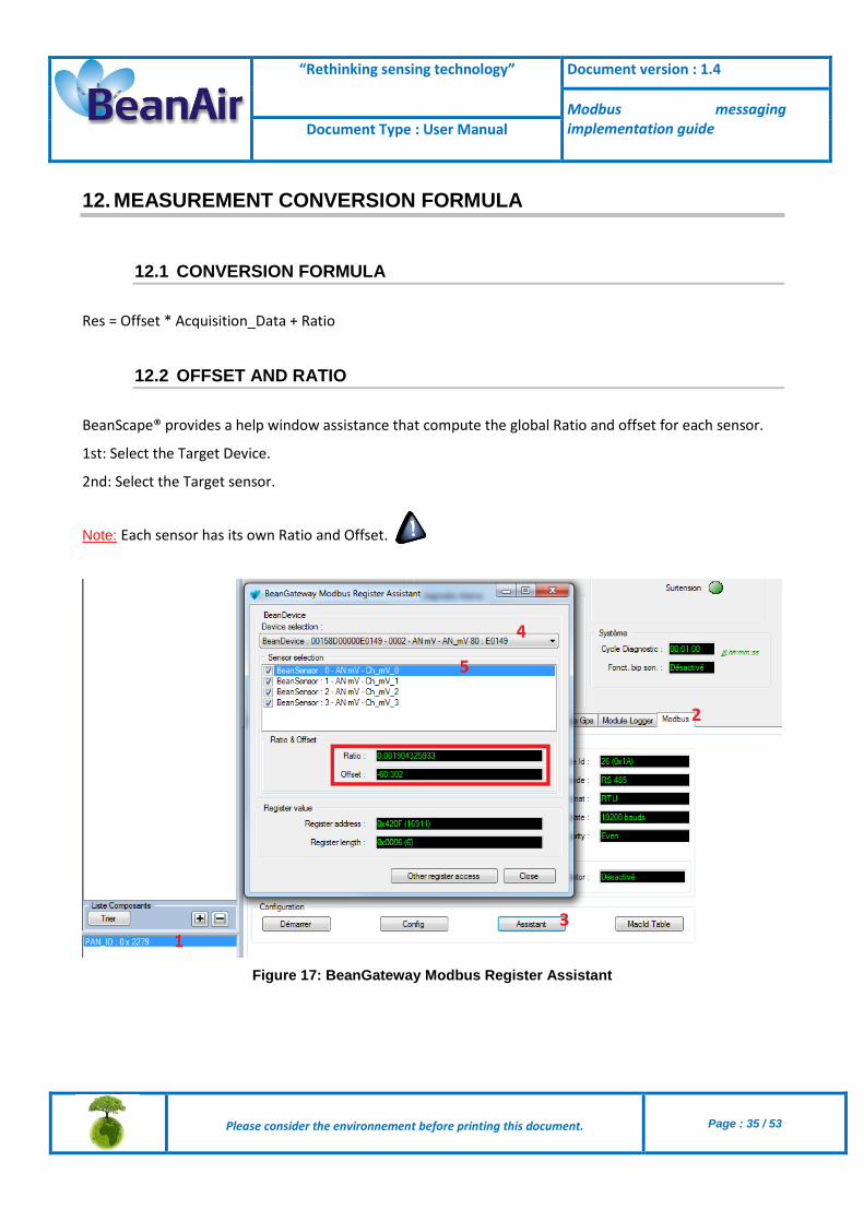
12.2 OFFSET AND RATIO
BeanScape® provides a help window assistance that compute the global Ratio and offset for each sensor.
1st: Select the Target Device.
2nd: Select the Target sensor.
Note: Each sensor has its own Ratio and Offset.
Figure 17: BeanGateway Modbus Register Assistant

“Rethinking sensing technology” Document version : 1.4
Modbus messaging implementation guide Document Type : User Manual
Please consider the environnement before printing this document.
Page : 36 / 53
Example
Figure 18: Measurement Conversion Example
“Rethinking sensing technology” Document version : 1.4
Modbus messaging implementation guide Document Type : User Manual
Please consider the environnement before printing this document.
Page : 37 / 53
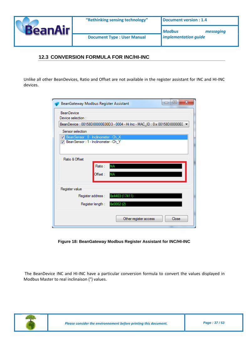
12.3 CONVERSION FORMULA FOR INC/HI-INC
Unlike all other BeanDevices, Ratio and Offset are not available in the register assistant for INC and HI-INC devices.
Figure 18: BeanGateway Modbus Register Assistant for INC/HI-INC
The BeanDevice INC and HI-INC have a particular conversion formula to convert the values displayed in Modbus Master to real inclinaison (°) values.

“Rethinking sensing technology” Document version : 1.4
Modbus messaging implementation guide Document Type : User Manual
Please consider the environnement before printing this document.
Page : 38 / 53
Given X, the value in Modbus, Y the real value is computed from the conversion formula below:
Y=Arcsin [(C*A*X) + B +D].
A, B: Calibration settings
C, D: Conversion settings
The calibration setting can be gotten directly from the BeanScape side on the sensor user control.
The conversion settings are calculated as follows:
C=1/SensibilityPt.
D= -32768*C.
The sensibility change according to the sensor range
Table of sensibilities in function of number of points

“Rethinking sensing technology” Document version : 1.4
Modbus messaging implementation guide Document Type : User Manual
Please consider the environnement before printing this document.
Page : 39 / 53
13. OTAC MANAGEMENT FROM MODBUS
It is possible to send OTACs (Over the Air Configuration) from the Modbus master to the Beangateway and to the BeanDevice in order to change the data acquisition mode or the power mode. The used register to set these parameters is “Write Multiple Registers (0x10)”.
The frame will be sent by writing in holding registers of the slave (Beangateway). There are 30 holding register (60 byte) reserved for receiving OTACs starting from address 1000.
“Rethinking sensing technology” Document version : 1.4
Modbus messaging implementation guide Document Type : User Manual
Please consider the environnement before printing this document.
Page : 40 / 53
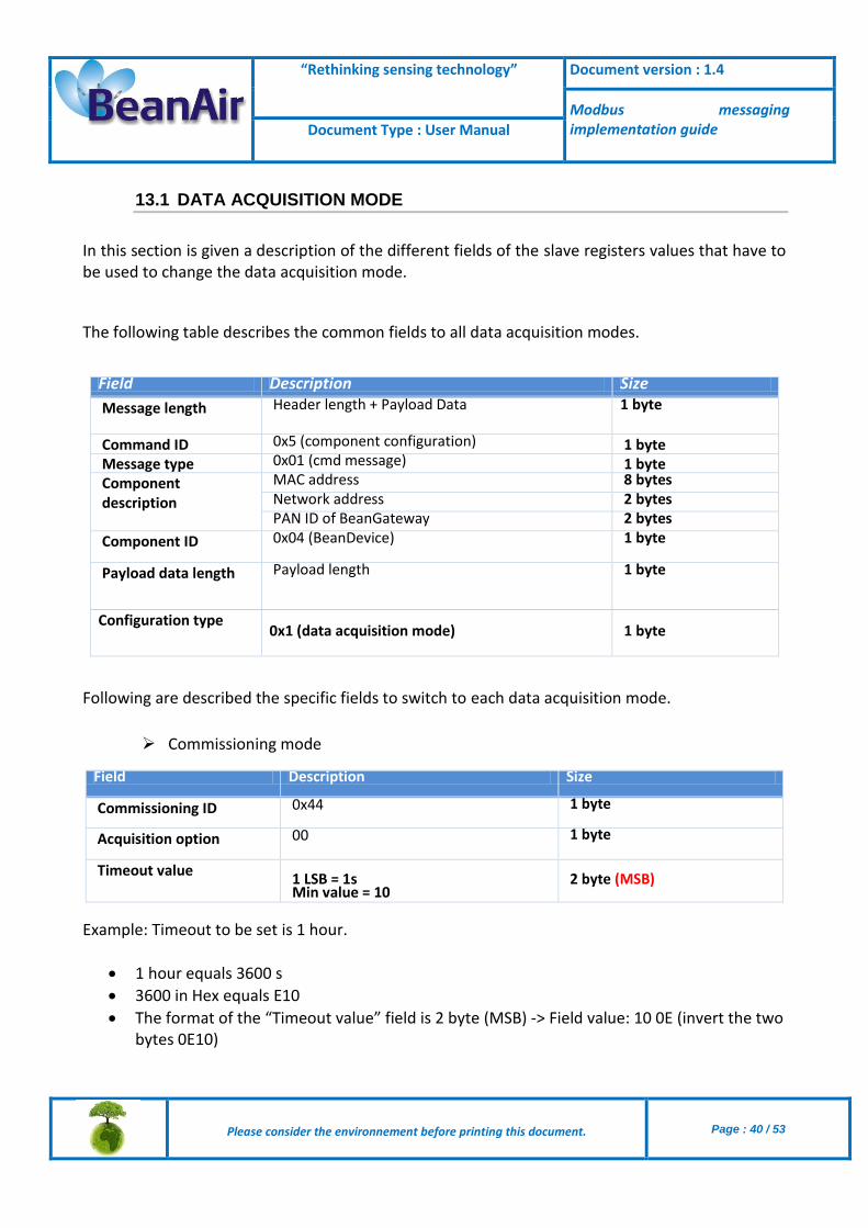
13.1 DATA ACQUISITION MODE
In this section is given a description of the different fields of the slave registers values that have to be used to change the data acquisition mode.
The following table describes the common fields to all data acquisition modes.
Field Description Size
Message length Header length + Payload Data 1 byte
Command ID 0x5 (component configuration) 1 byte Message type 0x01 (cmd message) 1 byte Component description
MAC address 8 bytes Network address 2 bytes PAN ID of BeanGateway 2 bytes
Component ID 0x04 (BeanDevice) 1 byte
Payload data length Payload length 1 byte
Configuration type 0x1 (data acquisition mode)
1 byte
Following are described the specific fields to switch to each data acquisition mode.
Commissioning mode
Field Description Size
Commissioning ID 0x44 1 byte
Acquisition option 00 1 byte
Timeout value 1 LSB = 1s Min value = 10
2 byte (MSB)
Example: Timeout to be set is 1 hour.
1 hour equals 3600 s
3600 in Hex equals E10
The format of the “Timeout value” field is 2 byte (MSB) -> Field value: 10 0E (invert the two bytes 0E10)

“Rethinking sensing technology” Document version : 1.4
Modbus messaging implementation guide Document Type : User Manual
Please consider the environnement before printing this document.
Page : 41 / 53
Low duty cycle mode
Field Description Size
LDCDA ID 0x11 1 byte
Acquisition option Bitmap
Bit0 : temperature compensation Bit1 : voltage compensation Bit2+bit3: 01: Tx 10: Log 11: Tx + Log
Bit4: Bit5: Bit6: SA option Bit7:
1 byte
Transmission cycle
Min value = 1s Max value = 1 day
4 byte (MSB)
Example: Transmission cycle to be set is 1 hour.
1 hour equals 3600 s
3600 in Hex equals E10
The format of the “Transmission cycle” field is 4 byte (MSB) -> Field value: 10 0E 00 00 (invert the four bytes 00 00 0E 10)
Survey mode
Field Description Size
Survey ID 0x23 1 byte
Acquisition option Bitmap
Bit0 : temperature compensation Bit1 : voltage compensation Bit2+bit3: 01: Tx 10: Log 11: Tx + Log
Bit4: Bit5: Bit6: SA option Bit7:
1 byte
Acquisition cycle (Cm) Min value = 1s Max value = 1 year Unit : s
4 byte (MSB)
Transmission cycle (Ct) Min value = 1s Max value = 1 year Unit : s
4 byte (MSB)
Ct should be a multiple of Cm.
“Rethinking sensing technology” Document version : 1.4
Modbus messaging implementation guide Document Type : User Manual
Please consider the environnement before printing this document.
Page : 42 / 53
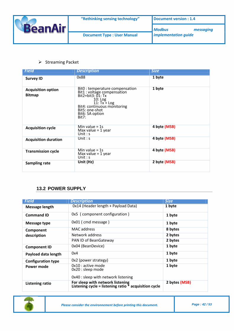
Streaming Packet
Field Description Size
Survey ID 0x88 1 byte
Acquisition option Bitmap
Bit0 : temperature compensation Bit1 : voltage compensation Bit2+bit3: 01: Tx 10: Log 11: Tx + Log
Bit4: continuous monitoring Bit5: one-shot Bit6: SA option Bit7:
1 byte
Acquisition cycle Min value = 1s Max value = 1 year Unit : s
4 byte (MSB)
Acquisition duration Unit : s 4 byte (MSB)
Transmission cycle Min value = 1s Max value = 1 year Unit : s
4 byte (MSB)
Sampling rate Unit (Hz) 2 byte (MSB)
13.2 POWER SUPPLY
Field Description Size Message length 0x14 (Header length + Payload Data) 1 byte
Command ID 0x5 ( component configuration ) 1 byte
Message type 0x01 ( cmd message ) 1 byte
Component description
MAC address 8 bytes
Network address 2 bytes PAN ID of BeanGateway 2 bytes
Component ID 0x04 (BeanDevice) 1 byte
Payload data length 0x4 1 byte
Configuration type 0x2 (power strategy) 1 byte
Power mode 0x10 : active mode 0x20 : sleep mode
0x40 : sleep with network listening
1 byte
Listening ratio For sleep with network listening Listening cycle = listening ratio * acquisition cycle
2 bytes (MSB)

“Rethinking sensing technology” Document version : 1.4
Modbus messaging implementation guide Document Type : User Manual
Please consider the environnement before printing this document.
Page : 43 / 53
13.3 EXAMPLE
In the following examples we have: MacID = 0x00158D00000E02A9 PanId = 0x0012 NetId = 0x0001
Example 1: Commissioning mode with timeout (1hour): 1505 0100 158D 0000 0E02 A900 0100 1204 0501 4400 100E Example 2: LDCDA with Tx only data acquisition cycle 30 days: 1705 0100 158d 0000 0e02 a900 0100 1204 0701 1104 008d 2700 Example 3: set active power mode: 1405 0100 158d 0000 0E02 A900 0100 1204 0402 1000
Please find following a video
OTAC management video – Switch to commissioning mode with 1 hour timeout.

“Rethinking sensing technology” Document version : 1.4
Modbus messaging implementation guide Document Type : User Manual
Please consider the environnement before printing this document.
Page : 44 / 53
14. S401-I MODULE
In this section, we describe the communication between the s401-l module and the BeanGatway via Modbus (serial/RS485).
The S401-l is a Modbus (RTU / RS485) indicator which will be used to periodically get data from the Beangateway and display it.
The S401-l module should be powered by: - From 10v to 40v with direct current. OR -From 19v to 28v with alternating current.
As shown in the figure hereafter, the S401-l has 2 Modbus interfaces:
Master interface: which is used to communicate with the gateway.
Slave interface: it can be used to configure the module via Znet3 software delivered by Seneca and can be downloaded from there: http://www.seneca.it/media/1120/seneca_znet3_200_beta_41.zip

“Rethinking sensing technology” Document version : 1.4
Modbus messaging implementation guide Document Type : User Manual
Please consider the environnement before printing this document.
Page : 45 / 53
14.1 WIRING CODE (RS485 MASTER)

“Rethinking sensing technology” Document version : 1.4
Modbus messaging implementation guide Document Type : User Manual
Please consider the environnement before printing this document.
Page : 46 / 53
Pin Number Wire color Function
PIN1 Orange/White Rx-
PIN2 Orange Rx+
PIN3 Green/White Not used
PIN4 Blue Tx+
PIN5 Blue/White Tx-
PIN6 Green Not used
PIN7 Brown/White Not used
PIN8 Brown Ground

“Rethinking sensing technology” Document version : 1.4
Modbus messaging implementation guide Document Type : User Manual
Please consider the environnement before printing this document.
Page : 47 / 53
14.2 ADD A NEW BEANDEVICE
Step 1: From Main Menu, select Readings
Step 2: From readings, select Insert New
Step 3: Insert BeanDevice description using up/ down arrows and OK Menu push button.
Step 4: Select confirm and click ok
Step 5: Enter slave address and click OK
Step 6: Select confirm and click ok

“Rethinking sensing technology” Document version : 1.4
Modbus messaging implementation guide Document Type : User Manual
Please consider the environnement before printing this document.
Page : 48 / 53
Step 7: Select Data Format and click ok
Step 8: Select confirm and click ok
Step 9: Enter measure unit and click ok
Step 10: Select confirm and click ok
Step 11: Select data offset format and click ok
Step 12: Enter offset value and click ok
Step 13: Select ratio format and click ok
Step 14: Enter ratio value and click ok

“Rethinking sensing technology” Document version : 1.4
Modbus messaging implementation guide Document Type : User Manual
Please consider the environnement before printing this document.
Page : 49 / 53
14.3 S401-I MODULE DISPLAY
After adding the BeanDevice, the S401_I module displays exactly the same values displayed in Beanscape.
You can find below an example with three BeanDevices (AX-3D, ONE-TIR, INC).

“Rethinking sensing technology” Document version : 1.4
Modbus messaging implementation guide Document Type : User Manual
Please consider the environnement before printing this document.
Page : 50 / 53

“Rethinking sensing technology” Document version : 1.4
Modbus messaging implementation guide Document Type : User Manual
Please consider the environnement before printing this document.
Page : 51 / 53
15. APPENDICES
15.1 APPENDIX 1: TESTING WITH QMODBUS
QModBus is a free Qt-based implementation of a ModBus master application. A graphical user interface allows easy communication with ModBus slaves over serial line interface. QModBus also includes a bus monitor for examining all traffic on the bus.
User can download QModBus from this link: Click here
The following picture shows a representation of QModbus configured to work with the BeanGateway® ModBus over RS485.
In this example, QModbus was configured to read 3 axis measurements provided by the BeanDevice® AX-3D:
Select the serial port, Baud rate (ex: 115.2 Kbits/s) , Data Bits (ex: 8), Stop Bits (2) , Parity (none)
Slave ID (26), Function Code (Read Input Registers 0x04), Start Address 16647, Number of coils (3)
Figure 19 : QModBus Screenshot

“Rethinking sensing technology” Document version : 1.4
Modbus messaging implementation guide Document Type : User Manual
Please consider the environnement before printing this document.
Page : 52 / 53
To get the “Start Address” value, use the ModBus Assistant available on the ModBud configurator on the BeanScape® software
The ModBus frame available on BeanScape® software was configured as follow:
Figure 20 : ModBus RS485 configuration on the BeanScape®
13.2 APPENDIX 1: EXAMPLE VIDEOS
Modbus configuration via RS232-QModMaster
Modbus configuration via RS485- ModScan64 Master
Modbus configuration via TCP (Ethernet)- QModMaster
Related Documents


![DPU2000/1500R/2000R MODBUS / MODBUS PLUS … · DPU2000/1500R/2000R Modbus/Modbus Plus Automation Guide i DPU2000/1500R/2000R MODBUS / MODBUS PLUS ... [Catalog 587XXX00-XXX0 or 587XXXX6-XXX4]](https://static.cupdf.com/doc/110x72/5acb9eac7f8b9a73128bdc42/dpu20001500r2000r-modbus-modbus-plus-modbusmodbus-plus-automation-guide.jpg)


