UPS2000-G-3KRTLL User Manual Issue 01 Date 2020-10-26 HUAWEI TECHNOLOGIES CO., LTD.

Welcome message from author
This document is posted to help you gain knowledge. Please leave a comment to let me know what you think about it! Share it to your friends and learn new things together.
Transcript
UPS2000-G-3KRTLL
User Manual
Issue 01
Date 2020-10-26
HUAWEI TECHNOLOGIES CO., LTD.
Copyright © Huawei Technologies Co., Ltd. 2020. All rights reserved.
No part of this document may be reproduced or transmitted in any form or by any means without priorwritten consent of Huawei Technologies Co., Ltd.
Trademarks and Permissions
and other Huawei trademarks are trademarks of Huawei Technologies Co., Ltd.All other trademarks and trade names mentioned in this document are the property of their respectiveholders.
NoticeThe purchased products, services and features are stipulated by the contract made between Huawei andthe customer. All or part of the products, services and features described in this document may not bewithin the purchase scope or the usage scope. Unless otherwise specified in the contract, all statements,information, and recommendations in this document are provided "AS IS" without warranties, guaranteesor representations of any kind, either express or implied.
The information in this document is subject to change without notice. Every effort has been made in thepreparation of this document to ensure accuracy of the contents, but all statements, information, andrecommendations in this document do not constitute a warranty of any kind, express or implied.
Huawei Technologies Co., Ltd.Address:
Website:
Huawei Industrial Base Bantian, Longgang Shenzhen 518129 People's Republic of China
https://e.huawei.com
Issue 01 (2020-10-26) Copyright © Huawei Technologies Co., Ltd. i
About This Document
PurposeThis document describes the UPS2000-G-3KRTLL in terms of features,performance, appearance, structure, working principle, installation, operation, andmaintenance.
NO TE
● The UPS applies only to commercial and industrial use, rather than medical facilities andlife support equipment.
● The UPS belongs to C2 (Class A) UPSs. If you use it in residual areas, take installationrestriction or additional measures to prevent radio frequency interferences.
Intended AudienceThis document is intended for:
● Sales engineers
● Technical support engineers
● System engineers
● Hardware installation engineers
● Commissioning engineers
● Data configuration engineers
● Maintenance engineers
Symbol ConventionsThe symbols that may be found in this document are defined as follows.
Symbol Description
Indicates a hazard with a high level of risk which,if not avoided, will result in death or seriousinjury.
UPS2000-G-3KRTLLUser Manual About This Document
Issue 01 (2020-10-26) Copyright © Huawei Technologies Co., Ltd. ii
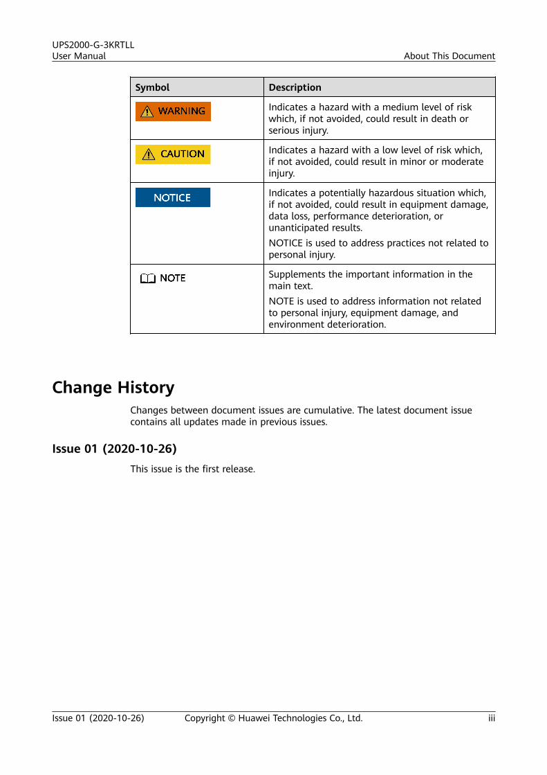
Symbol Description
Indicates a hazard with a medium level of riskwhich, if not avoided, could result in death orserious injury.
Indicates a hazard with a low level of risk which,if not avoided, could result in minor or moderateinjury.
Indicates a potentially hazardous situation which,if not avoided, could result in equipment damage,data loss, performance deterioration, orunanticipated results.NOTICE is used to address practices not related topersonal injury.
Supplements the important information in themain text.NOTE is used to address information not relatedto personal injury, equipment damage, andenvironment deterioration.
Change HistoryChanges between document issues are cumulative. The latest document issuecontains all updates made in previous issues.
Issue 01 (2020-10-26)This issue is the first release.
UPS2000-G-3KRTLLUser Manual About This Document
Issue 01 (2020-10-26) Copyright © Huawei Technologies Co., Ltd. iii
Contents
About This Document................................................................................................................ ii
1 Safety Information.................................................................................................................. 11.1 General Safety.......................................................................................................................................................................... 11.2 Personnel Requirements....................................................................................................................................................... 41.3 Electrical Safety........................................................................................................................................................................41.4 Installation Environment Requirements.......................................................................................................................... 61.5 Mechanical Safety................................................................................................................................................................... 71.6 Device Running Safety........................................................................................................................................................ 101.7 Battery Safety......................................................................................................................................................................... 121.8 Others....................................................................................................................................................................................... 13
2 System Composition............................................................................................................. 142.1 Model Description................................................................................................................................................................ 142.2 Working Principle..................................................................................................................................................................152.3 Product Structure.................................................................................................................................................................. 152.4 Communication Ports.......................................................................................................................................................... 162.5 Battery Module...................................................................................................................................................................... 18
3 Installation..............................................................................................................................233.1 Installation Preparations.................................................................................................................................................... 233.2 Installation Tools................................................................................................................................................................... 243.3 Installing a UPS..................................................................................................................................................................... 253.4 Preparing Power Cables...................................................................................................................................................... 273.5 Installing Cables for a Single UPS................................................................................................................................... 283.6 Installing Cables for Parallel UPSs.................................................................................................................................. 303.7 Installing Communications Cables..................................................................................................................................333.8 Verifying the Installation.................................................................................................................................................... 34
4 Control Panel..........................................................................................................................364.1 LCD Introduction................................................................................................................................................................... 364.1.1 LCD......................................................................................................................................................................................... 364.1.2 Buttons.................................................................................................................................................................................. 394.1.3 LCD Screen Information.................................................................................................................................................. 404.2 LCD Character Display.........................................................................................................................................................424.3 Parameter Settings............................................................................................................................................................... 44
UPS2000-G-3KRTLLUser Manual Contents
Issue 01 (2020-10-26) Copyright © Huawei Technologies Co., Ltd. iv
4.4 Operating Modes.................................................................................................................................................................. 534.5 Alarm Types............................................................................................................................................................................ 554.5.1 Critical Alarms.................................................................................................................................................................... 554.5.2 Minor Alarms...................................................................................................................................................................... 574.6 Alarm Handling..................................................................................................................................................................... 60
5 Operations.............................................................................................................................. 915.1 Checking Before Power-On................................................................................................................................................915.2 Single UPS Operations........................................................................................................................................................ 915.2.1 Starting a UPS.................................................................................................................................................................... 915.2.1.1 Start the UPS Using Mains Power............................................................................................................................ 925.2.1.2 Cold-Starting the UPS Using Batteries................................................................................................................... 945.2.2 Shutting Down a UPS...................................................................................................................................................... 965.2.3 Performing EPO..................................................................................................................................................................965.3 Parallel System Operations............................................................................................................................................... 975.3.1 Starting a Parallel System.............................................................................................................................................. 975.3.1.1 Start the UPSs Using Mains Power.......................................................................................................................... 975.3.1.2 Cold-Starting the UPSs Using Batteries................................................................................................................. 995.3.2 Shutting Down a Parallel System.............................................................................................................................. 1005.3.3 Performing EPO............................................................................................................................................................... 101
6 UPS Maintenance................................................................................................................ 102
7 Technical Specifications.....................................................................................................1047.1 Physical Specifications...................................................................................................................................................... 1047.2 Environmental Specifications......................................................................................................................................... 1047.3 Mains Input Electrical Specifications........................................................................................................................... 1057.4 Bypass Input Electrical Specifications.......................................................................................................................... 1057.5 Output Electrical Specifications..................................................................................................................................... 1067.6 Battery Electrical Specifications.....................................................................................................................................1077.7 ECO Specifications..............................................................................................................................................................1087.8 Parallel System Specifications........................................................................................................................................ 1097.9 Safety and EMC................................................................................................................................................................... 109
A Acronyms and Abbreviations........................................................................................... 111
UPS2000-G-3KRTLLUser Manual Contents
Issue 01 (2020-10-26) Copyright © Huawei Technologies Co., Ltd. v
1 Safety Information
1.1 General Safety
StatementBefore installing, operating, and maintaining the equipment, read this documentand observe all the safety instructions on the equipment and in this document.
The "NOTICE", "CAUTION", "WARNING", and "DANGER" statements in thisdocument do not cover all the safety instructions. They are only supplements tothe safety instructions. Huawei will not be liable for any consequence caused bythe violation of general safety requirements or design, production, and usagesafety standards.
Ensure that the equipment is used in environments that meet its designspecifications. Otherwise, the equipment may become faulty, and the resultingequipment malfunction, component damage, personal injuries, or propertydamage are not covered under the warranty.
Follow local laws and regulations when installing, operating, or maintaining theequipment. The safety instructions in this document are only supplements to locallaws and regulations.
Huawei will not be liable for any consequences of the following circumstances:
● Operation beyond the conditions specified in this document● Installation or use in environments which are not specified in relevant
international or national standards● Unauthorized modifications to the product or software code or removal of the
product● Failure to follow the operation instructions and safety precautions on the
product and in this document● Equipment damage due to force majeure, such as earthquakes, fire, and
storms● Damage caused during transportation by the customer● Storage conditions that do not meet the requirements specified in this
document
UPS2000-G-3KRTLLUser Manual 1 Safety Information
Issue 01 (2020-10-26) Copyright © Huawei Technologies Co., Ltd. 1
General Requirements● Do not install, use, or operate outdoor equipment and cables (including but
not limited to moving equipment, operating equipment and cables, insertingconnectors to or removing connectors from signal ports connected to outdoorfacilities, working at heights, and performing outdoor installation) in harshweather conditions such as lightning, rain, snow, and level 6 or stronger wind.
● Before installing, operating, or maintaining the equipment, remove anyconductive objects such as watches or metal jewelry like bracelets, bangles,and rings to avoid electric shock.
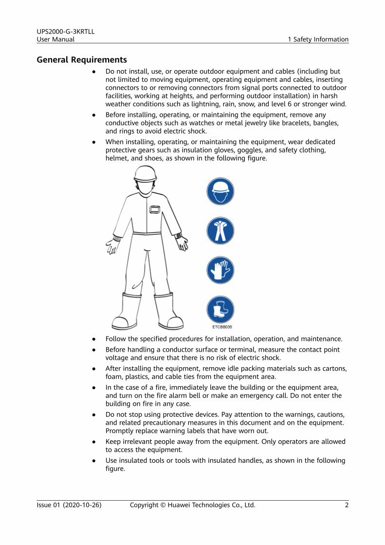
● When installing, operating, or maintaining the equipment, wear dedicatedprotective gears such as insulation gloves, goggles, and safety clothing,helmet, and shoes, as shown in the following figure.
● Follow the specified procedures for installation, operation, and maintenance.● Before handling a conductor surface or terminal, measure the contact point
voltage and ensure that there is no risk of electric shock.● After installing the equipment, remove idle packing materials such as cartons,
foam, plastics, and cable ties from the equipment area.● In the case of a fire, immediately leave the building or the equipment area,
and turn on the fire alarm bell or make an emergency call. Do not enter thebuilding on fire in any case.
● Do not stop using protective devices. Pay attention to the warnings, cautions,and related precautionary measures in this document and on the equipment.Promptly replace warning labels that have worn out.
● Keep irrelevant people away from the equipment. Only operators are allowedto access the equipment.
● Use insulated tools or tools with insulated handles, as shown in the followingfigure.
UPS2000-G-3KRTLLUser Manual 1 Safety Information
Issue 01 (2020-10-26) Copyright © Huawei Technologies Co., Ltd. 2
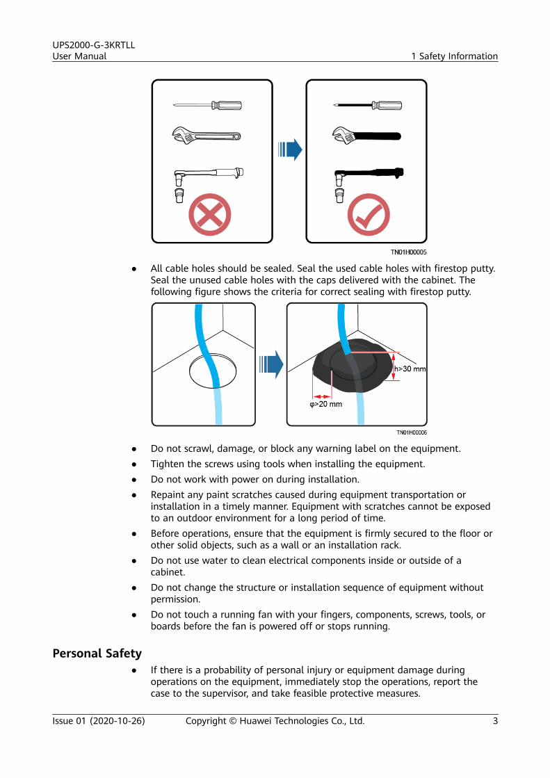
● All cable holes should be sealed. Seal the used cable holes with firestop putty.Seal the unused cable holes with the caps delivered with the cabinet. Thefollowing figure shows the criteria for correct sealing with firestop putty.
● Do not scrawl, damage, or block any warning label on the equipment.● Tighten the screws using tools when installing the equipment.● Do not work with power on during installation.● Repaint any paint scratches caused during equipment transportation or
installation in a timely manner. Equipment with scratches cannot be exposedto an outdoor environment for a long period of time.
● Before operations, ensure that the equipment is firmly secured to the floor orother solid objects, such as a wall or an installation rack.
● Do not use water to clean electrical components inside or outside of acabinet.
● Do not change the structure or installation sequence of equipment withoutpermission.
● Do not touch a running fan with your fingers, components, screws, tools, orboards before the fan is powered off or stops running.
Personal Safety● If there is a probability of personal injury or equipment damage during
operations on the equipment, immediately stop the operations, report thecase to the supervisor, and take feasible protective measures.
UPS2000-G-3KRTLLUser Manual 1 Safety Information
Issue 01 (2020-10-26) Copyright © Huawei Technologies Co., Ltd. 3
● To avoid electric shock, do not connect safety extra-low voltage (SELV) circuitsto telecommunication network voltage (TNV) circuits.
● Do not power on the equipment before it is installed or confirmed byprofessionals.
1.2 Personnel Requirements● Personnel who plan to install or maintain Huawei equipment must receive
thorough training, understand all necessary safety precautions, and be able tocorrectly perform all operations.
● Only qualified professionals or trained personnel are allowed to install,operate, and maintain the equipment.
● Only qualified professionals are allowed to remove safety facilities and inspectthe equipment.
● Personnel who will operate the equipment, including operators, trainedpersonnel, and professionals, should possess the local national requiredqualifications in special operations such as high-voltage operations, workingat heights, and operations of special equipment.
● Professionals: personnel who are trained or experienced in equipmentoperations and are clear of the sources and degree of various potentialhazards in equipment installation, operation, maintenance
● Trained personnel: personnel who are technically trained, have requiredexperience, are aware of possible hazards on themselves in certain operations,and are able to take protective measures to minimize the hazards onthemselves and other people
● Operators: operation personnel who may come in contact with theequipment, except trained personnel and professionals
● Only professionals or authorized personnel are allowed to replace theequipment or components (including software).
1.3 Electrical Safety
Grounding● For the equipment that needs to be grounded, install the ground cable first
when installing the equipment and remove the ground cable last whenremoving the equipment.
● Do not damage the ground conductor.● Do not operate the equipment in the absence of a properly installed ground
conductor.● Ensure that the equipment is connected permanently to the protective
ground. Before operating the equipment, check its electrical connection toensure that it is securely grounded.
General Requirements
Use dedicated insulated tools when performing high-voltage operations.
UPS2000-G-3KRTLLUser Manual 1 Safety Information
Issue 01 (2020-10-26) Copyright © Huawei Technologies Co., Ltd. 4
AC and DC Power
D ANGER
Do not connect or disconnect power cables with power on. Transient contactbetween the core of the power cable and the conductor will generate electric arcsor sparks, which may cause fire or personal injury.
● If a "high electricity leakage" tag is attached on the equipment, ground theprotective ground terminal on the equipment enclosure before connecting theAC power supply; otherwise, electric shock as a result of electricity leakagemay occur.
● Before installing or removing a power cable, turn off the power switch.● Before connecting a power cable, check that the label on the power cable is
correct.● If the equipment has multiple inputs, disconnect all the inputs before
operating the equipment.● A circuit breaker equipped with a residual current device (RCD) is not
recommended.● A damaged power cable must be replaced by the manufacturer, service agent,
or professionals to avoid risks.● High voltage operations and installation of AC-powered facilities must be
performed by qualified personnel.
Cabling● When routing cables, ensure that a distance of at least 30 mm exists between
the cables and heat-generating components or areas. This prevents damageto the insulation layer of the cables.
● Do not route cables behind the air intake and exhaust vents of theequipment.
● Ensure that cables meet the VW-1 or ZB flame spread rating requirements orhigher.
● Bind cables of the same type together. When routing cables of different types,ensure that they are at least 30 mm away from each other.
● If an AC input power cable is connected to the cabinet from the top, bend thecable in a U shape outside the cabinet and then route it into the cabinet.
● When the temperature is low, violent impact or vibration may damage theplastic cable sheathing. To ensure safety, comply with the followingrequirements:– Cables can be laid or installed only when the temperature is higher than
0°C. Handle cables with caution, especially at a low temperature.– Cables stored at subzero temperatures must be stored at room
temperature for at least 24 hours before they are laid out.● Do not perform any improper operations, for example, dropping cables
directly from a vehicle.● When selecting, connecting, and routing cables, follow local safety regulations
and rules.
UPS2000-G-3KRTLLUser Manual 1 Safety Information
Issue 01 (2020-10-26) Copyright © Huawei Technologies Co., Ltd. 5
ESD
NO TICE
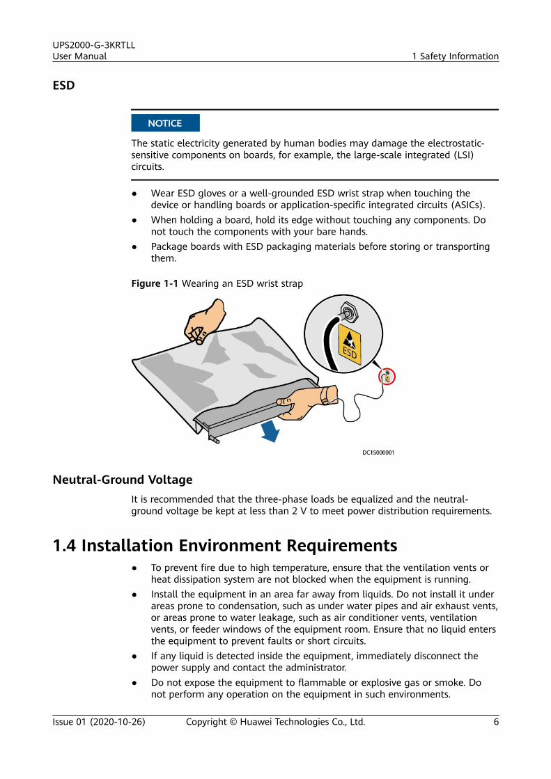
The static electricity generated by human bodies may damage the electrostatic-sensitive components on boards, for example, the large-scale integrated (LSI)circuits.
● Wear ESD gloves or a well-grounded ESD wrist strap when touching thedevice or handling boards or application-specific integrated circuits (ASICs).
● When holding a board, hold its edge without touching any components. Donot touch the components with your bare hands.
● Package boards with ESD packaging materials before storing or transportingthem.
Figure 1-1 Wearing an ESD wrist strap
Neutral-Ground VoltageIt is recommended that the three-phase loads be equalized and the neutral-ground voltage be kept at less than 2 V to meet power distribution requirements.
1.4 Installation Environment Requirements● To prevent fire due to high temperature, ensure that the ventilation vents or
heat dissipation system are not blocked when the equipment is running.● Install the equipment in an area far away from liquids. Do not install it under
areas prone to condensation, such as under water pipes and air exhaust vents,or areas prone to water leakage, such as air conditioner vents, ventilationvents, or feeder windows of the equipment room. Ensure that no liquid entersthe equipment to prevent faults or short circuits.
● If any liquid is detected inside the equipment, immediately disconnect thepower supply and contact the administrator.
● Do not expose the equipment to flammable or explosive gas or smoke. Donot perform any operation on the equipment in such environments.
UPS2000-G-3KRTLLUser Manual 1 Safety Information
Issue 01 (2020-10-26) Copyright © Huawei Technologies Co., Ltd. 6
● Ensure that the equipment room provides good heat insulation, and the wallsand floor are dampproof.
● Install a rat guard at the door of the equipment room.
Installation at Heights● Working at heights refers to operations that are performed at least 2 meters
above the ground.● Do not work at heights if the steel pipes are wet or other potential danger
exists. After the preceding conditions no longer exist, the safety director andrelevant technical personnel need to check the involved equipment. Operatorscan begin working only after obtaining consent.
● When working at heights, comply with local relevant laws and regulations.● Only trained and qualified personnel are allowed to work at heights.● Before working at heights, check the climbing tools and safety gears such as
safety helmets, safety belts, ladders, springboards, scaffolding, and liftingequipment. If they do not meet the requirements, take corrective measures ordisallow working at heights.
● Wear personal protective equipment such as the safety helmet and safety beltor waist rope and fasten it to a solid structure. Do not mount it on aninsecure moveable object or metal object with sharp edges. Make sure thatthe hooks will not slide off.
● Set a restricted area and eye-catching signs for working at heights to warnaway irrelevant personnel.
● Carry the operation machinery and tools properly to prevent them fromfalling off and causing injuries.
● Personnel involving working at heights are not allowed to throw objects fromthe height to the ground, or vice versa. Objects should be transported bytough slings, hanging baskets, highline trolleys, or cranes.
● Ensure that guard rails and warning signs are set at the edges and openingsof the area involving working at heights to prevent falls.
● Do not pile up scaffolding, springboards, or other sundries on the groundunder the area involving working at heights. Do not allow people to stay orpass under the area involving working at heights.
● Inspect the scaffolding, springboards, and workbenches used for working atheights in advance to ensure that their structures are solid and notoverloaded.
● Any violations must be promptly pointed out by the site manager or safetysupervisor and the involved personnel should be prompted for correction.Personnel who fail to stop violations will be forbidden from working.
1.5 Mechanical Safety
Hoisting Devices● Do not walk under hoisted objects.● Only trained and qualified personnel should perform hoisting operations.
UPS2000-G-3KRTLLUser Manual 1 Safety Information
Issue 01 (2020-10-26) Copyright © Huawei Technologies Co., Ltd. 7
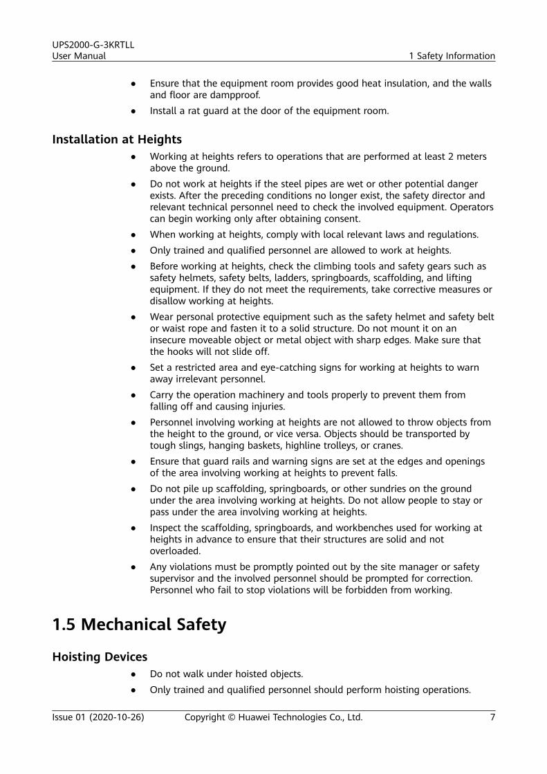
● Check that hoisting tools are available and in good condition.● Before hoisting objects, ensure that hoisting tools are firmly secured onto a
load-bearing object or wall.● Ensure that the angle formed by two hoisting cables is no more than 90
degrees, as shown in the following figure.
● Do not drag steel ropes and hoisting tools or bump hoisted objects againsthard objects during hoisting.
Using Ladders● Use wooden or fiberglass ladders when you need to perform live working at
heights.● When a step ladder is used, ensure that the pull ropes are secured and the
ladder is held firm.● Before using a ladder, check that it is intact and confirm its load bearing
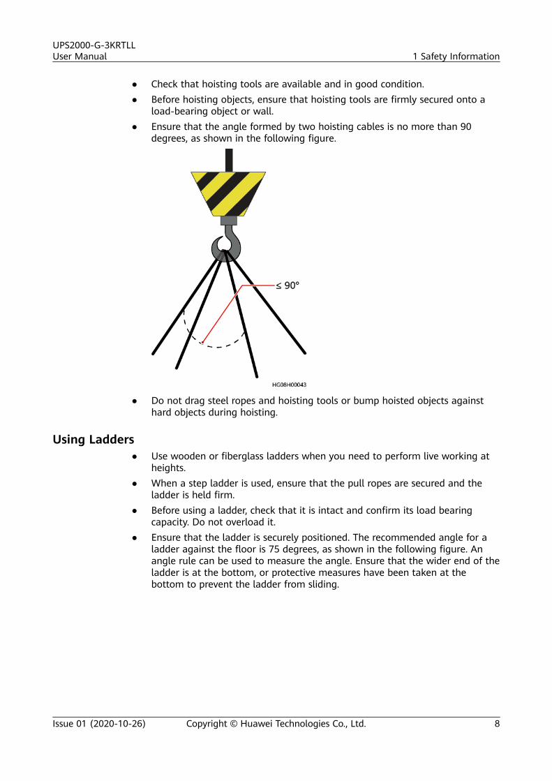
capacity. Do not overload it.● Ensure that the ladder is securely positioned. The recommended angle for a
ladder against the floor is 75 degrees, as shown in the following figure. Anangle rule can be used to measure the angle. Ensure that the wider end of theladder is at the bottom, or protective measures have been taken at thebottom to prevent the ladder from sliding.
UPS2000-G-3KRTLLUser Manual 1 Safety Information
Issue 01 (2020-10-26) Copyright © Huawei Technologies Co., Ltd. 8
● When climbing a ladder, take the following precautions to reduce risks andensure safety:
– Keep your body steady.
– Do not climb higher than the fourth rung of the ladder from the top.
– Ensure that your body's center of gravity does not shift outside the legsof the ladder.
Drilling Holes
When drilling holes into a wall or floor, observe the following safety precautions:
NO TICE
Do not drill holes into the equipment. Doing so may affect the electromagneticshielding of the equipment and damage components or cables inside. Metalshavings from drilling may short-circuit boards inside the equipment.
● Obtain the consent from the customer and subcontractor before drilling.
● Wear goggles and protective gloves when drilling holes.
● When drilling holes, protect the equipment from shavings. After drilling, cleanup any shavings that have accumulated inside or outside the equipment.
Moving Heavy Objects
D ANGER
When removing a heavy or unstable component from a cabinet, be aware ofunstable or heavy objects on the cabinet.
● Be cautious to avoid injury when moving heavy objects.
UPS2000-G-3KRTLLUser Manual 1 Safety Information
Issue 01 (2020-10-26) Copyright © Huawei Technologies Co., Ltd. 9
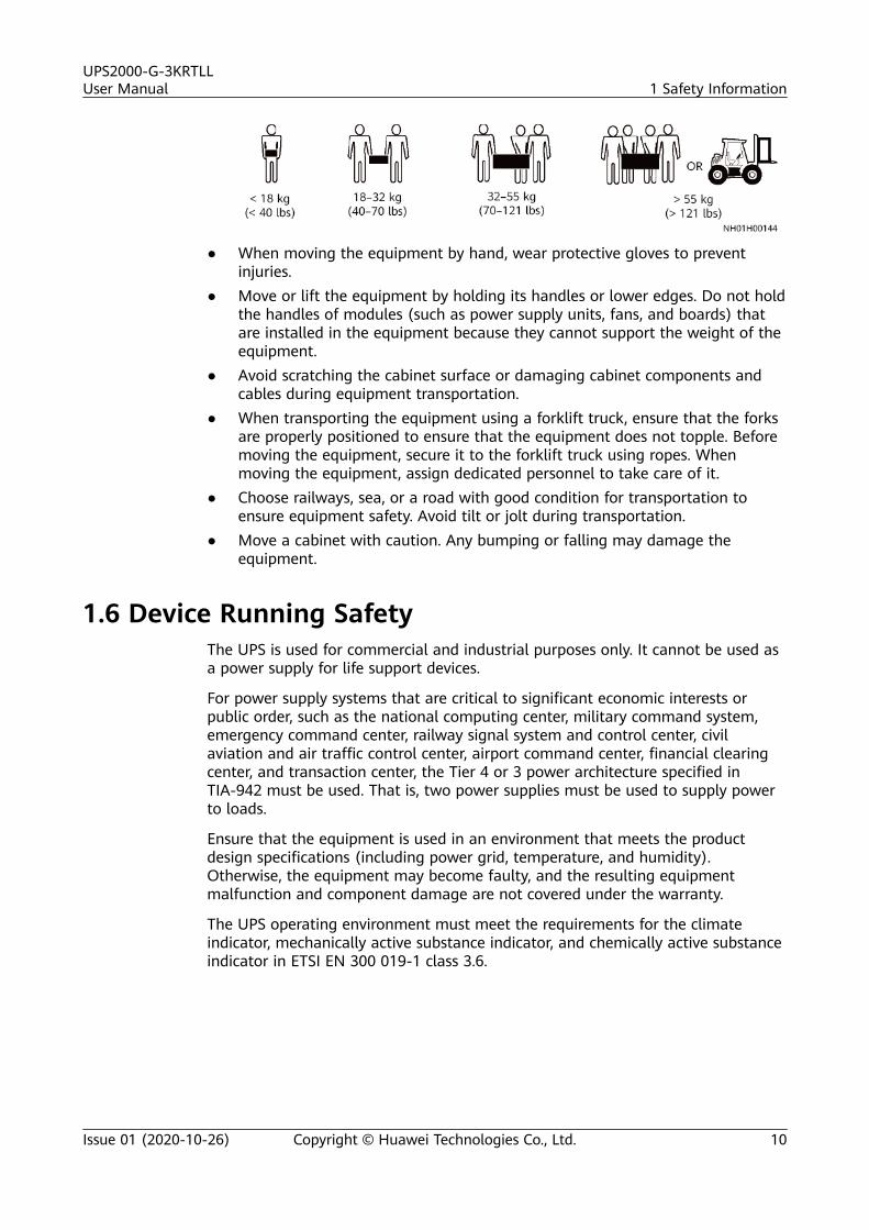
● When moving the equipment by hand, wear protective gloves to preventinjuries.
● Move or lift the equipment by holding its handles or lower edges. Do not holdthe handles of modules (such as power supply units, fans, and boards) thatare installed in the equipment because they cannot support the weight of theequipment.
● Avoid scratching the cabinet surface or damaging cabinet components andcables during equipment transportation.
● When transporting the equipment using a forklift truck, ensure that the forksare properly positioned to ensure that the equipment does not topple. Beforemoving the equipment, secure it to the forklift truck using ropes. Whenmoving the equipment, assign dedicated personnel to take care of it.
● Choose railways, sea, or a road with good condition for transportation toensure equipment safety. Avoid tilt or jolt during transportation.
● Move a cabinet with caution. Any bumping or falling may damage theequipment.
1.6 Device Running SafetyThe UPS is used for commercial and industrial purposes only. It cannot be used asa power supply for life support devices.
For power supply systems that are critical to significant economic interests orpublic order, such as the national computing center, military command system,emergency command center, railway signal system and control center, civilaviation and air traffic control center, airport command center, financial clearingcenter, and transaction center, the Tier 4 or 3 power architecture specified inTIA-942 must be used. That is, two power supplies must be used to supply powerto loads.
Ensure that the equipment is used in an environment that meets the productdesign specifications (including power grid, temperature, and humidity).Otherwise, the equipment may become faulty, and the resulting equipmentmalfunction and component damage are not covered under the warranty.
The UPS operating environment must meet the requirements for the climateindicator, mechanically active substance indicator, and chemically active substanceindicator in ETSI EN 300 019-1 class 3.6.
UPS2000-G-3KRTLLUser Manual 1 Safety Information
Issue 01 (2020-10-26) Copyright © Huawei Technologies Co., Ltd. 10
NO TICE
● After unpacking the UPS, you are advised to power on the UPS as soon aspossible. If you temporarily do not use the UPS, take appropriate measures toprevent moisture, dust, and foreign matter from entering the UPS.
● Install the UPS in an area far away from liquids. Do not install it under areasprone to water leakage, such as air conditioner vents, ventilation vents, orfeeder windows of the equipment room. Ensure that no liquid enters the UPSto prevent short circuits. Ensure that there is no condensation inside theequipment or equipment room.
● If any liquid is detected inside the equipment, immediately disconnect thepower supply and contact the administrator.
D ANGER
● Do not expose the equipment to flammable or explosive gas or smoke. Do notperform any operation on the equipment in such environments.
● During installation and maintenance, ensure that sundries do not enter theUPS. Otherwise, equipment damage, load power derating, power failure, andpersonal injury may occur.
The UPS can be used to serve resistive-capacitive loads, resistive loads, and micro-inductive loads. It is not applicable to pure capacitive loads, pure inductive loads,half-wave rectification loads, or regenerative loads.
Any operation on any electrical device in an environment that has inflammable aircan cause extreme danger. Strictly obey the operating environmental requirementsspecified in related user manuals when using or storing the device.
Do not use the UPS in the following places:
● Environments that are exposed to flammable, explosive, or corrosive gases ordust, conductive or magnetic dust, abnormal vibration, or collision
● Rooms or outdoor environments where temperature and humidity are notcontrolled (with high temperature, low temperature, moisture, direct sunlight,or heat sources)
● Non-confined environments near the ocean (0–3.7 km) and indoor or semi-indoor environments where the temperature and humidity are notcontrollable, such as simple equipment rooms, civil houses, garages, corridors,and direct ventilation cabinets near the ocean; or houses with only roofs,railway station platforms, gymnasiums, and aquariums
● Environments that are conducive for the growth of microorganisms such asfungus or mildew
● Environments where rodents (such as mice) and insects exist
UPS2000-G-3KRTLLUser Manual 1 Safety Information
Issue 01 (2020-10-26) Copyright © Huawei Technologies Co., Ltd. 11
1.7 Battery Safety
Basic RequirementsBefore operating batteries, carefully read the safety precautions for batteryhandling and master the correct battery connection methods.
D ANGER
● Do not expose batteries at high temperatures or around heat-generatingdevices, such as sunlight, fire sources, transformers, and heaters. Overheatingmay cause the batteries to explode.
● Do not burn batteries. Otherwise, the batteries may explode.
● Use dedicated insulated tools.● Move batteries in the required direction. Do not place a battery upside down
or tilt it.● Keep the battery loop disconnected during installation and maintenance.● Use batteries of specified models. Using batteries of other models may
damage the batteries.● Dispose of waste batteries in accordance with local laws and regulations. Do
not dispose of batteries as household waste. If a battery is disposed ofimproperly, it may explode.
● The site must be equipped with qualified fire extinguishing facilities, such asfirefighting sands and powder fire extinguishers.
NO TICE
To ensure battery safety and battery management accuracy, use batteries providedwith the UPS by Huawei. Huawei is not responsible for any battery faults causedby batteries not provided by Huawei.
Battery InstallationBefore installing batteries, observe the following safety precautions:
● Install batteries in a well-ventilated, dry, and cool environment that is faraway from heat sources, flammable materials, moisture, extensive infraredradiation, organic solvents, and corrosive gases. Take fire preventionmeasures.
● Place and secure batteries horizontally.● Note the polarities when installing batteries. Do not short-circuit the positive
and negative poles of the same battery or battery string. Otherwise, thebattery may be short-circuited.
● Check battery connections periodically, ensuring that all screws are securelytightened.
UPS2000-G-3KRTLLUser Manual 1 Safety Information
Issue 01 (2020-10-26) Copyright © Huawei Technologies Co., Ltd. 12
● When installing batteries, do not place installation tools on the batteries.
Battery Short Circuit
D ANGER
Battery short circuits can generate high instantaneous current and release a greatamount of energy, which may cause equipment damage or personal injury.
To avoid battery short circuit, do not maintain batteries with power on.
Lithium Battery
The safety precautions for lithium batteries are similar to those for lead-acidbatteries except that you also need to observe the following precautions.
WARNING
There is a risk of explosion if a battery is replaced with an incorrect model.
● A battery can be replaced only with a battery of the same or similar modelrecommended by the manufacturer.
● When handling a lithium battery, do not place it upside down, tilt it, or bumpit with other objects.
● Keep the lithium battery loop disconnected during installation andmaintenance.
● Do not charge a battery when the ambient temperature is below the lowerlimit of the operating temperature (charging is forbidden at 0°C). Low-temperature charging may cause crystallization, which will result in a shortcircuit inside the battery.
● Use batteries within the allowed temperature range; otherwise, the batteryperformance and safety will be compromised.
● Do not throw a lithium battery in fire.
● When maintenance is complete, return the waste lithium battery to themaintenance office.
1.8 Others● Exercise caution when manually shutting down the UPS inverter for
transferring to bypass mode, or when adjusting the UPS output voltage levelor frequency. Doing so may affect the power supply to equipment.
● Exercise caution when setting battery parameters. Incorrect settings will affectthe power supply and battery lifespan.
UPS2000-G-3KRTLLUser Manual 1 Safety Information
Issue 01 (2020-10-26) Copyright © Huawei Technologies Co., Ltd. 13
2 System Composition
2.1 Model DescriptionThis document describes the following UPS model:
Table 2-1 UPS model
Model Represented By Remarks
UPS2000-G-3KRTLL 3kVA This model isabbreviated to a 3 kVAUPS in this document.
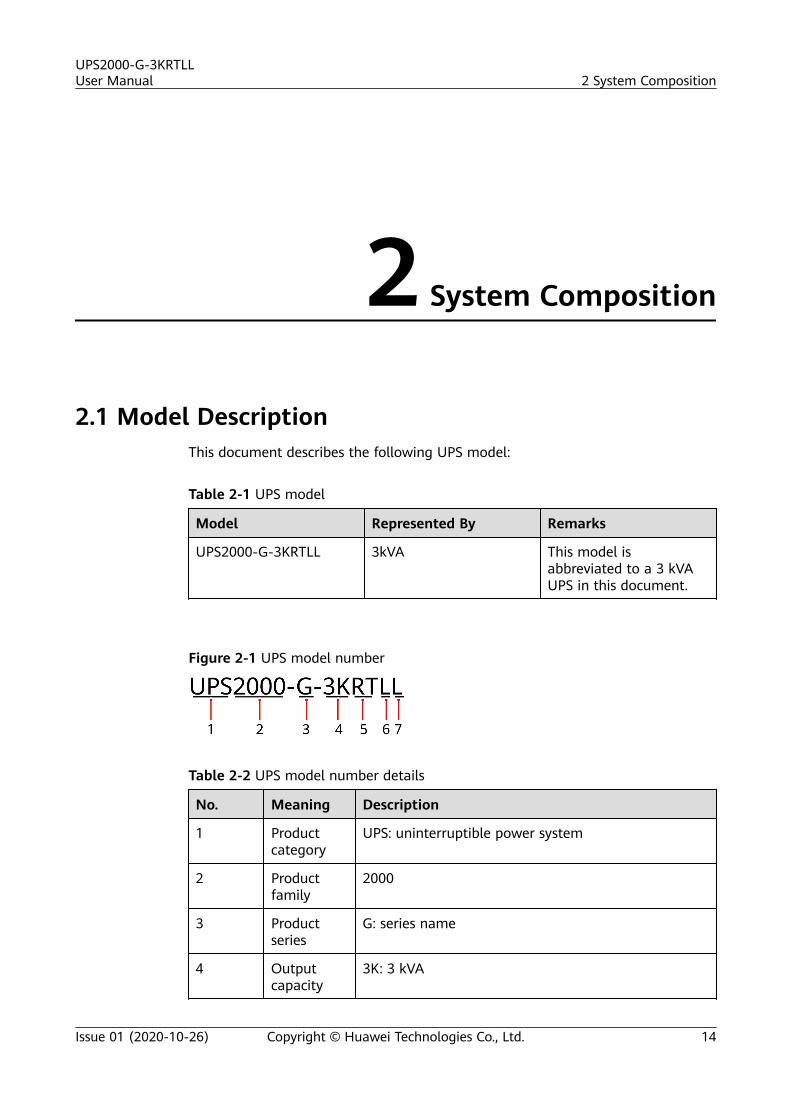
Figure 2-1 UPS model number
Table 2-2 UPS model number details
No. Meaning Description
1 Productcategory
UPS: uninterruptible power system
2 Productfamily
2000
3 Productseries
G: series name
4 Outputcapacity
3K: 3 kVA
UPS2000-G-3KRTLLUser Manual 2 System Composition
Issue 01 (2020-10-26) Copyright © Huawei Technologies Co., Ltd. 14
No. Meaning Description
5 UPS type RT: rack-mounted or tower-mounted
6 Longbackuptime model
L: long backup time model, using external large-capacity batteries that provide long backup time
7 Externalbatterytype
L: LFP battery
2.2 Working Principle
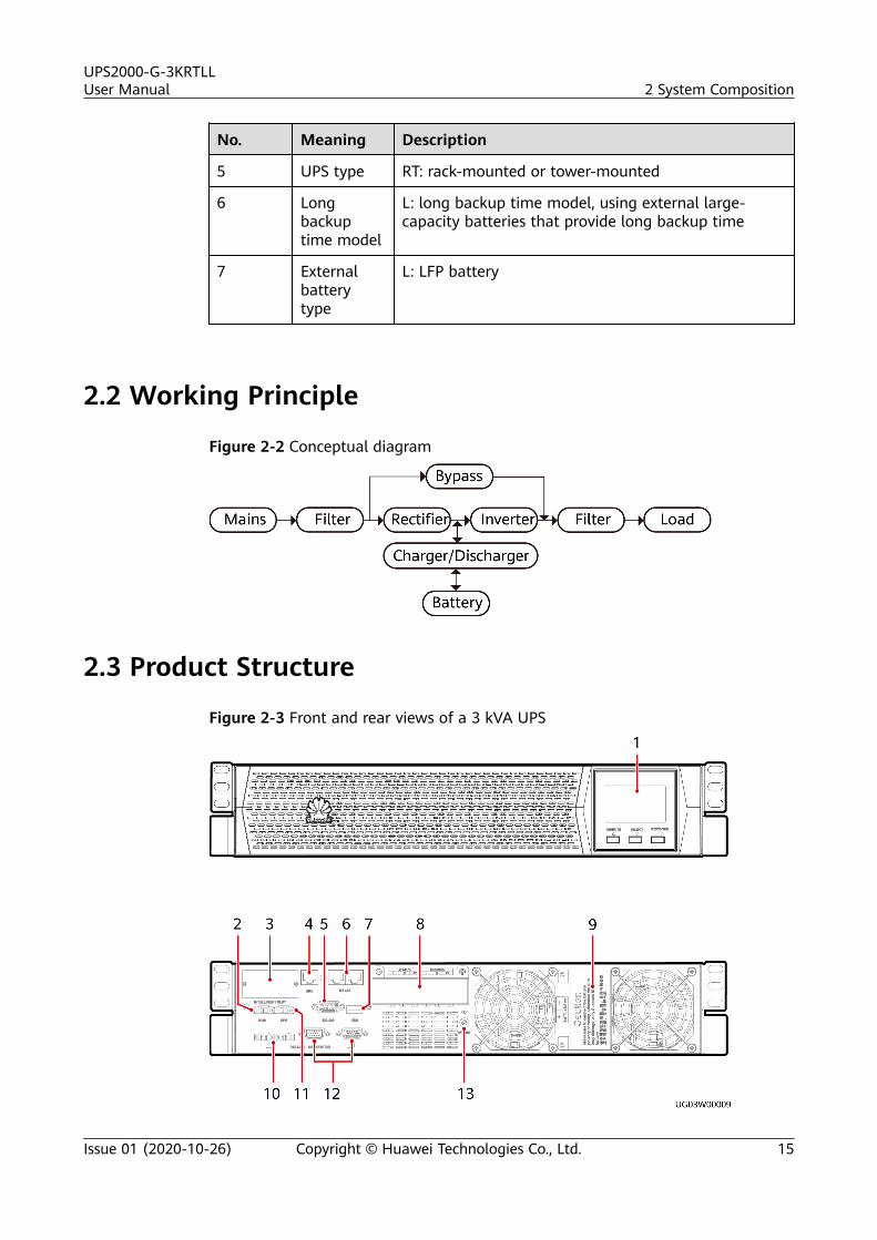
Figure 2-2 Conceptual diagram
2.3 Product Structure
Figure 2-3 Front and rear views of a 3 kVA UPS
UPS2000-G-3KRTLLUser Manual 2 System Composition
Issue 01 (2020-10-26) Copyright © Huawei Technologies Co., Ltd. 15
(1) Liquid crystal display(LCD)
(2) Maintenance bypass (MBS)port
(3) Optional cardslot
(4) Batterymanagement system(BMS) port
(5) RS232 communicationsportb
(6) RS485communicationsports (connect tonorthbounddevices)
(7) USB porta (8) AC input and outputterminals (behind the cover)
(9) Battery inputterminal (behindthe cover)
(10) Parallel currentequalization port
(11) Emergency power-off(EPO) port
(12) Parallelcommunicationports
(13) Battery PE terminal
NO TE
● The RS485 port supports only the Modbus RTU protocol.
● The USB port and RS232 port cannot be used at the same time.
a: The USB port supports the serial port communication protocol. The USB port can beused to export logs and send serial port commissioning commands.
b: The RS232 port supports the serial port communication protocol. The RS232 port canbe used to export logs, send serial port commissioning commands, and upgrade the UPSmain power program online.
2.4 Communication Ports
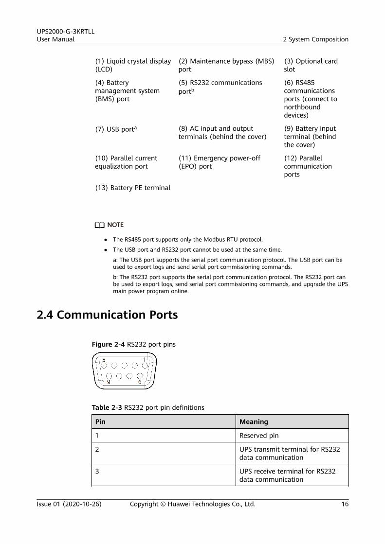
Figure 2-4 RS232 port pins
Table 2-3 RS232 port pin definitions
Pin Meaning
1 Reserved pin
2 UPS transmit terminal for RS232data communication
3 UPS receive terminal for RS232data communication
UPS2000-G-3KRTLLUser Manual 2 System Composition
Issue 01 (2020-10-26) Copyright © Huawei Technologies Co., Ltd. 16
Pin Meaning
4 Reserved pin
5 Common terminal for RS232 datacommunication
6–9 Reserved pin
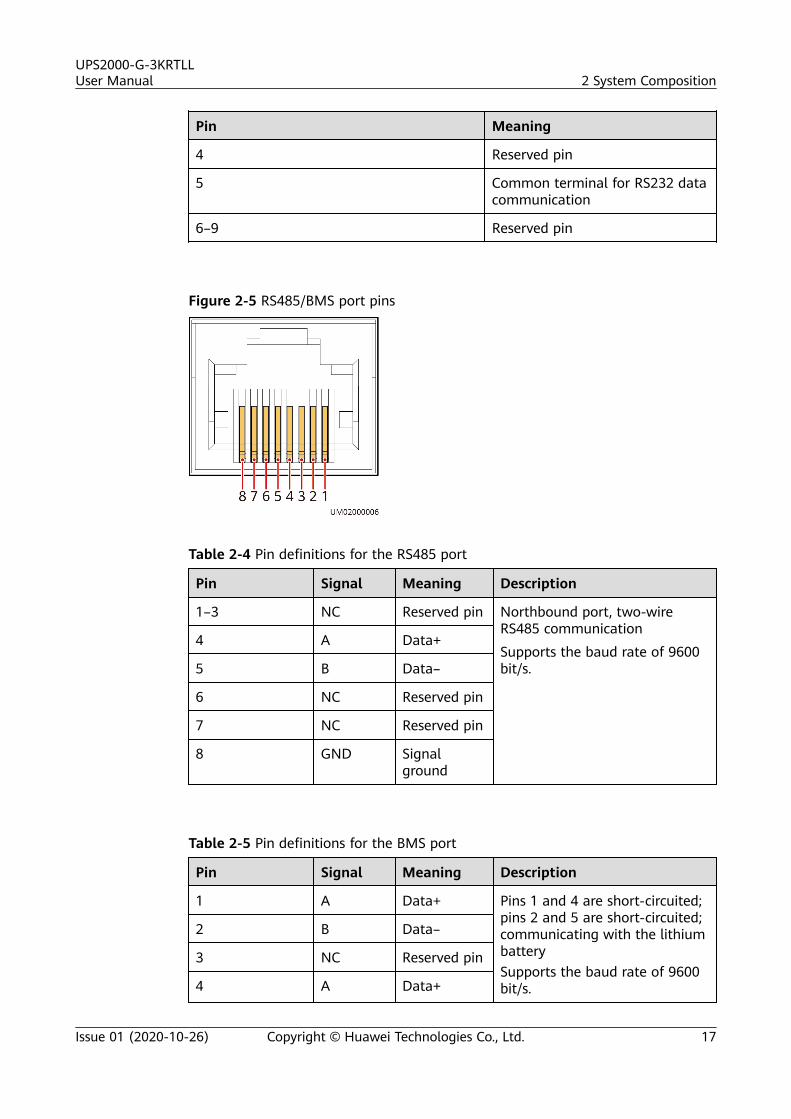
Figure 2-5 RS485/BMS port pins
Table 2-4 Pin definitions for the RS485 port
Pin Signal Meaning Description
1–3 NC Reserved pin Northbound port, two-wireRS485 communication
Supports the baud rate of 9600bit/s.
4 A Data+
5 B Data–
6 NC Reserved pin
7 NC Reserved pin
8 GND Signalground
Table 2-5 Pin definitions for the BMS port
Pin Signal Meaning Description
1 A Data+ Pins 1 and 4 are short-circuited;pins 2 and 5 are short-circuited;communicating with the lithiumbatterySupports the baud rate of 9600bit/s.
2 B Data–
3 NC Reserved pin
4 A Data+
UPS2000-G-3KRTLLUser Manual 2 System Composition
Issue 01 (2020-10-26) Copyright © Huawei Technologies Co., Ltd. 17
Pin Signal Meaning Description
5 B Data–
6 NC Reserved pin
7 NC Reserved pin
8 GND Signalground
2.5 Battery Module
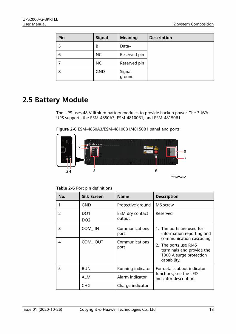
The UPS uses 48 V lithium battery modules to provide backup power. The 3 kVAUPS supports the ESM-4850A3, ESM-48100B1, and ESM-48150B1.
Figure 2-6 ESM-4850A3/ESM-48100B1/48150B1 panel and ports
Table 2-6 Port pin definitions
No. Silk Screen Name Description
1 GND Protective ground M6 screw
2 DO1DO2
ESM dry contactoutput
Reserved.
3 COM_ IN Communicationsport
1. The ports are used forinformation reporting andcommunication cascading.
2. The ports use RJ45terminals and provide the1000 A surge protectioncapability.
4 COM_ OUT Communicationsport
5 RUN Running indicator For details about indicatorfunctions, see the LEDindicator description.ALM Alarm indicator
CHG Charge indicator
UPS2000-G-3KRTLLUser Manual 2 System Composition
Issue 01 (2020-10-26) Copyright © Huawei Technologies Co., Ltd. 18
No. Silk Screen Name Description
DCHG Dischargeindicator
SOC SOC indicator
6 MANUALON/OFF
Button formanual power-on/off
This is a contact button usedfor manual power-on/offand maintenance.
7 PWR ESMU port forconnecting to anexternal powersource
Reserved.
8 + ESM positiveterminal
Positive and negative portsof the ESM. They are securedby M6 screws. AppropriateOT terminals should be used.The required torque is 4.5–5.5 N·m and therecommended cable size is25 mm2. If the ESM is usedat a temperature below45°C, the cable size can besmaller but should be atleast 16 mm2.
- ESM negativeterminal
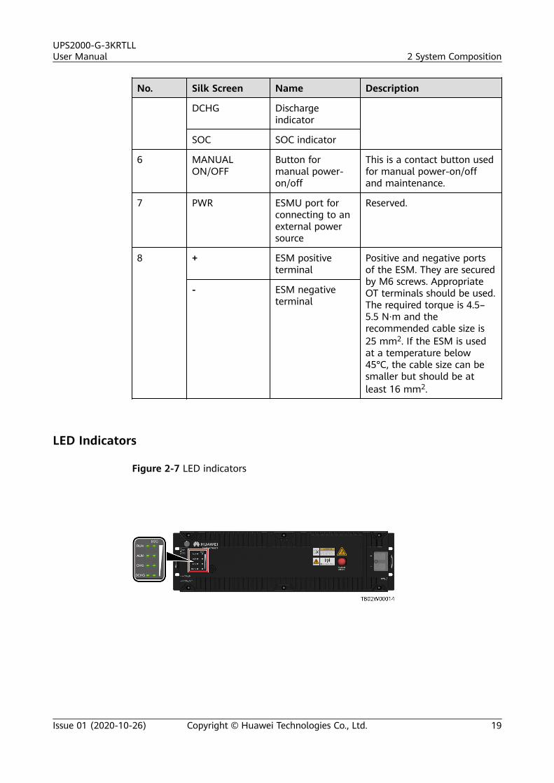
LED Indicators
Figure 2-7 LED indicators
UPS2000-G-3KRTLLUser Manual 2 System Composition
Issue 01 (2020-10-26) Copyright © Huawei Technologies Co., Ltd. 19
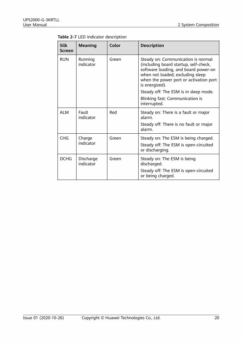
Table 2-7 LED indicator description
SilkScreen
Meaning Color Description
RUN Runningindicator
Green Steady on: Communication is normal(including board startup, self-check,software loading, and board power-onwhen not loaded; excluding sleepwhen the power port or activation portis energized).Steady off: The ESM is in sleep mode.Blinking fast: Communication isinterrupted.
ALM Faultindicator
Red Steady on: There is a fault or majoralarm.Steady off: There is no fault or majoralarm.
CHG Chargeindicator
Green Steady on: The ESM is being charged.Steady off: The ESM is open-circuitedor discharging.
DCHG Dischargeindicator
Green Steady on: The ESM is beingdischarged.Steady off: The ESM is open-circuitedor being charged.
UPS2000-G-3KRTLLUser Manual 2 System Composition
Issue 01 (2020-10-26) Copyright © Huawei Technologies Co., Ltd. 20
SilkScreen
Meaning Color Description
SOC SOCindicators
Green 1. 0–24% capacity25% indicator: blinkingOther SOC indicators: off2. 25%–49% capacity25% indicator: steady on50% indicator: blinkingOther SOC indicators: off3. 50%–74% capacity25% indicator: steady on50% indicator: steady on75% indicator: blinkingOther SOC indicators: off4. 75%–99% capacity25% indicator: steady on50% indicator: steady on75% indicator: steady on100% indicator: blinking5. 100% capacityThe four SOC indicators are steady on.
Note:● Major alarm: The ESM needs to be maintained immediately.● Minor alarm: The ESM does not require maintenance, but sends a reminder
to remote maintenance personnel.● Blinking slowly: on for 1s and then off for 1s.● Blinking fast: on for 0.125s and then off for 0.125s● If the SOC indicators are off and other indicators are blinking, the ESM enters
the maintenance mode.● When the ESM is in sleep mode, the fault indicator is off except for reverse-
connection protection.
Activation and StartupAn ESM can be activated in the following two modes. After being activated, theESM switches from sleep mode to disconnected mode.
● Activation through the MANUAL ON/OFF button: Hold down the MANUALON/OFF button on the ESM panel for at least 5s and less than 15s.
● Activation through the power port: Supply the DC input voltage of 43.2–58 V(50 Ah), 43.2–58 V (100 Ah), or 43.2–59 V (150 Ah) to the power terminal onthe front panel for at least 5s.
UPS2000-G-3KRTLLUser Manual 2 System Composition
Issue 01 (2020-10-26) Copyright © Huawei Technologies Co., Ltd. 21
NO TE
1. The MANUAL ON/OFF button is a contact button. The interval for pressing thebutton should be greater than 0.5s; otherwise, the operation is ineffective.
2. If you have powered off the ESM that is in charging, discharging, or disconnectedmode by holding down the MANUAL ON/OFF button, you need to hold down thisbutton again to reactivate the ESM.
UPS2000-G-3KRTLLUser Manual 2 System Composition
Issue 01 (2020-10-26) Copyright © Huawei Technologies Co., Ltd. 22
3 Installation
3.1 Installation Preparations
Floor Loading CapacityThe floor can bear the weight of the UPS and its optional components. In the caseof rack-mounted installation, ensure that the floor can also bear the weight of therack.
Installation Environment● Do not install the UPS in a high-temperature, low-temperature, or damp place
that is beyond the technical specifications.● Keep the UPS far away from water, heat sources, and flammable and
explosive substances. Install the UPS in an environment free of dust, volatilegas, salt, and corrosive materials. Avoid direct sunlight.
● Do not install the UPS in environments with conductive metal scraps in theair.
● The optimal operating temperatures for batteries are 20–30°C. Operatingtemperatures higher than 30°C shorten the battery lifespan, and operatingtemperatures lower than 20°C reduce the battery backup time.
Installation ClearancesReserve a clearance of at least 500 mm from the front and rear of the chassis.
UPS2000-G-3KRTLLUser Manual 3 Installation
Issue 01 (2020-10-26) Copyright © Huawei Technologies Co., Ltd. 23
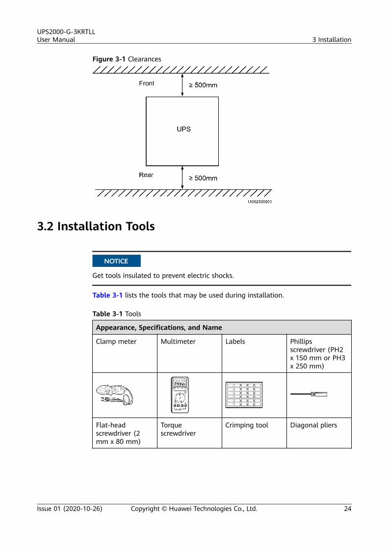
Figure 3-1 Clearances
3.2 Installation Tools
NO TICE
Get tools insulated to prevent electric shocks.
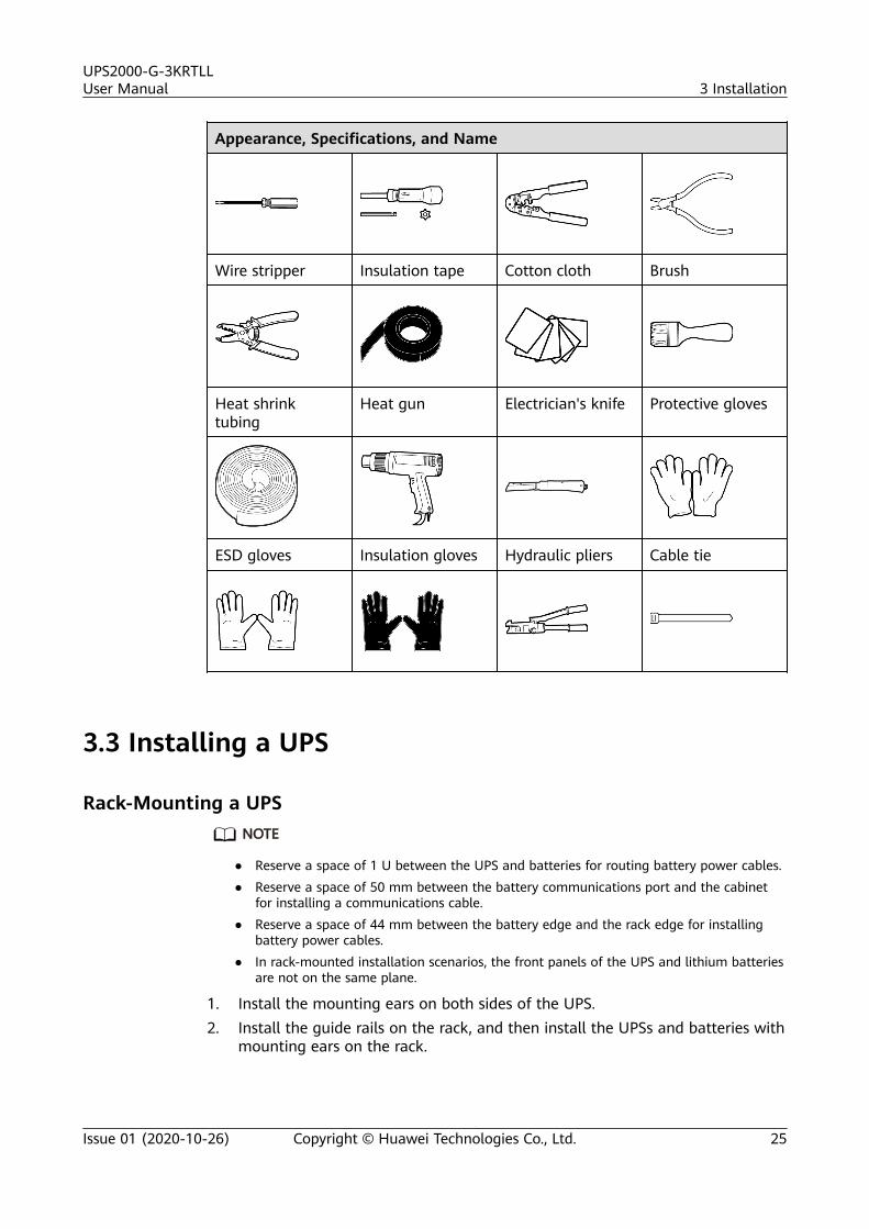
Table 3-1 lists the tools that may be used during installation.
Table 3-1 Tools
Appearance, Specifications, and Name
Clamp meter Multimeter Labels Phillipsscrewdriver (PH2x 150 mm or PH3x 250 mm)
Flat-headscrewdriver (2mm x 80 mm)
Torquescrewdriver
Crimping tool Diagonal pliers
UPS2000-G-3KRTLLUser Manual 3 Installation
Issue 01 (2020-10-26) Copyright © Huawei Technologies Co., Ltd. 24
Appearance, Specifications, and Name
Wire stripper Insulation tape Cotton cloth Brush
Heat shrinktubing
Heat gun Electrician's knife Protective gloves
ESD gloves Insulation gloves Hydraulic pliers Cable tie
3.3 Installing a UPS
Rack-Mounting a UPSNO TE
● Reserve a space of 1 U between the UPS and batteries for routing battery power cables.● Reserve a space of 50 mm between the battery communications port and the cabinet
for installing a communications cable.● Reserve a space of 44 mm between the battery edge and the rack edge for installing
battery power cables.● In rack-mounted installation scenarios, the front panels of the UPS and lithium batteries
are not on the same plane.
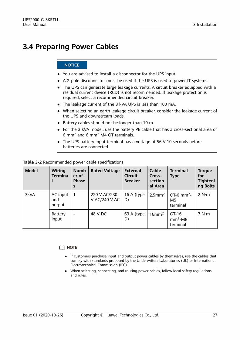
1. Install the mounting ears on both sides of the UPS.2. Install the guide rails on the rack, and then install the UPSs and batteries with
mounting ears on the rack.
UPS2000-G-3KRTLLUser Manual 3 Installation
Issue 01 (2020-10-26) Copyright © Huawei Technologies Co., Ltd. 25
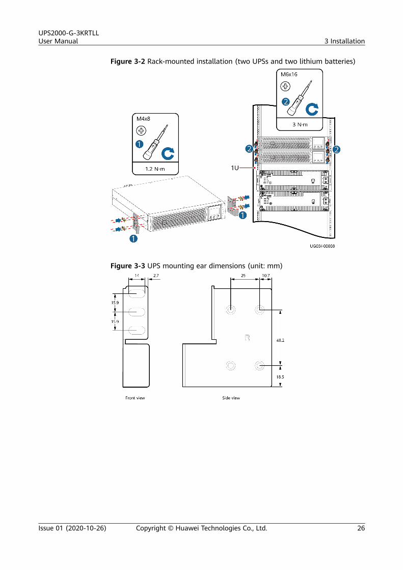
Figure 3-2 Rack-mounted installation (two UPSs and two lithium batteries)
Figure 3-3 UPS mounting ear dimensions (unit: mm)
UPS2000-G-3KRTLLUser Manual 3 Installation
Issue 01 (2020-10-26) Copyright © Huawei Technologies Co., Ltd. 26
3.4 Preparing Power Cables
NO TICE
● You are advised to install a disconnector for the UPS input.● A 2-pole disconnector must be used if the UPS is used to power IT systems.● The UPS can generate large leakage currents. A circuit breaker equipped with a
residual current device (RCD) is not recommended. If leakage protection isrequired, select a recommended circuit breaker.
● The leakage current of the 3 kVA UPS is less than 100 mA.● When selecting an earth leakage circuit breaker, consider the leakage current of
the UPS and downstream loads.● Battery cables should not be longer than 10 m.● For the 3 kVA model, use the battery PE cable that has a cross-sectional area of
6 mm2 and 6 mm2 M4 OT terminals.● The UPS battery input terminal has a voltage of 56 V 10 seconds before
batteries are connected.
Table 3-2 Recommended power cable specifications
Model WiringTerminal
Number ofPhases
Rated Voltage ExternalCircuitBreaker
CableCross-sectional Area
TerminalType
TorqueforTightening Bolts
3kVA AC inputandoutput
1 220 V AC/230V AC/240 V AC
16 A (typeD)
2.5mm2 OT-6 mm2-M5terminal
2 N·m
Batteryinput
- 48 V DC 63 A (typeD)
16mm2 OT-16mm2-M8terminal
7 N·m
NO TE
● If customers purchase input and output power cables by themselves, use the cables thatcomply with standards proposed by the Underwriters Laboratories (UL) or InternationalElectrotechnical Commission (IEC).
● When selecting, connecting, and routing power cables, follow local safety regulationsand rules.
UPS2000-G-3KRTLLUser Manual 3 Installation
Issue 01 (2020-10-26) Copyright © Huawei Technologies Co., Ltd. 27
3.5 Installing Cables for a Single UPS
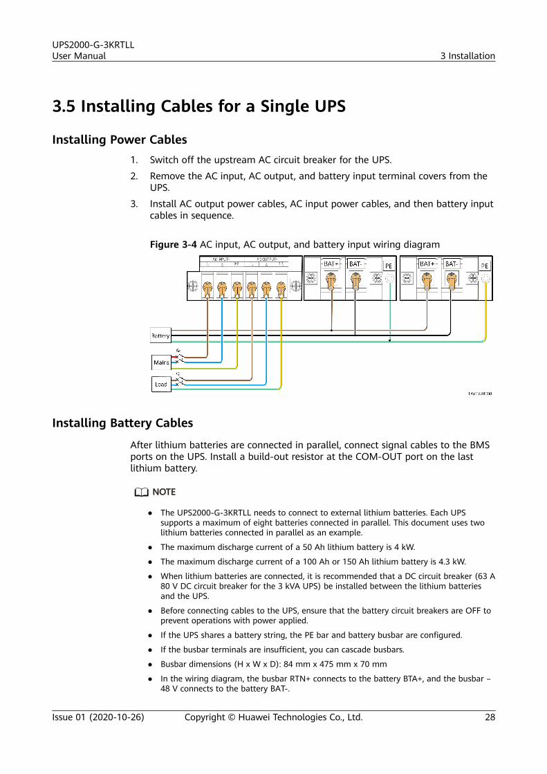
Installing Power Cables1. Switch off the upstream AC circuit breaker for the UPS.
2. Remove the AC input, AC output, and battery input terminal covers from theUPS.
3. Install AC output power cables, AC input power cables, and then battery inputcables in sequence.
Figure 3-4 AC input, AC output, and battery input wiring diagram
Installing Battery Cables
After lithium batteries are connected in parallel, connect signal cables to the BMSports on the UPS. Install a build-out resistor at the COM-OUT port on the lastlithium battery.
NO TE
● The UPS2000-G-3KRTLL needs to connect to external lithium batteries. Each UPSsupports a maximum of eight batteries connected in parallel. This document uses twolithium batteries connected in parallel as an example.
● The maximum discharge current of a 50 Ah lithium battery is 4 kW.
● The maximum discharge current of a 100 Ah or 150 Ah lithium battery is 4.3 kW.
● When lithium batteries are connected, it is recommended that a DC circuit breaker (63 A80 V DC circuit breaker for the 3 kVA UPS) be installed between the lithium batteriesand the UPS.
● Before connecting cables to the UPS, ensure that the battery circuit breakers are OFF toprevent operations with power applied.
● If the UPS shares a battery string, the PE bar and battery busbar are configured.
● If the busbar terminals are insufficient, you can cascade busbars.
● Busbar dimensions (H x W x D): 84 mm x 475 mm x 70 mm
● In the wiring diagram, the busbar RTN+ connects to the battery BTA+, and the busbar –48 V connects to the battery BAT-.
UPS2000-G-3KRTLLUser Manual 3 Installation
Issue 01 (2020-10-26) Copyright © Huawei Technologies Co., Ltd. 28
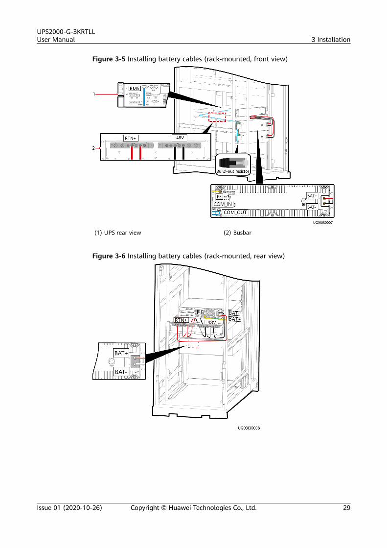
Figure 3-5 Installing battery cables (rack-mounted, front view)
(1) UPS rear view (2) Busbar
Figure 3-6 Installing battery cables (rack-mounted, rear view)
UPS2000-G-3KRTLLUser Manual 3 Installation
Issue 01 (2020-10-26) Copyright © Huawei Technologies Co., Ltd. 29
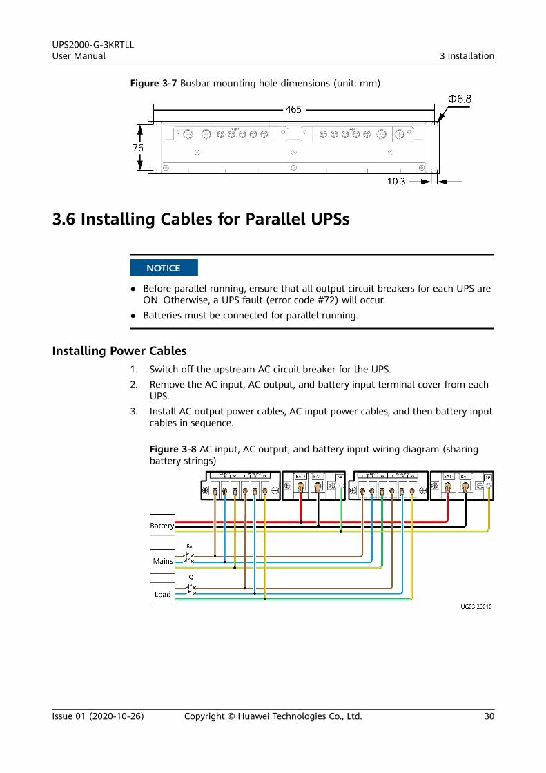
Figure 3-7 Busbar mounting hole dimensions (unit: mm)
3.6 Installing Cables for Parallel UPSs
NO TICE
● Before parallel running, ensure that all output circuit breakers for each UPS areON. Otherwise, a UPS fault (error code #72) will occur.
● Batteries must be connected for parallel running.
Installing Power Cables1. Switch off the upstream AC circuit breaker for the UPS.2. Remove the AC input, AC output, and battery input terminal cover from each
UPS.3. Install AC output power cables, AC input power cables, and then battery input
cables in sequence.
Figure 3-8 AC input, AC output, and battery input wiring diagram (sharingbattery strings)
UPS2000-G-3KRTLLUser Manual 3 Installation
Issue 01 (2020-10-26) Copyright © Huawei Technologies Co., Ltd. 30
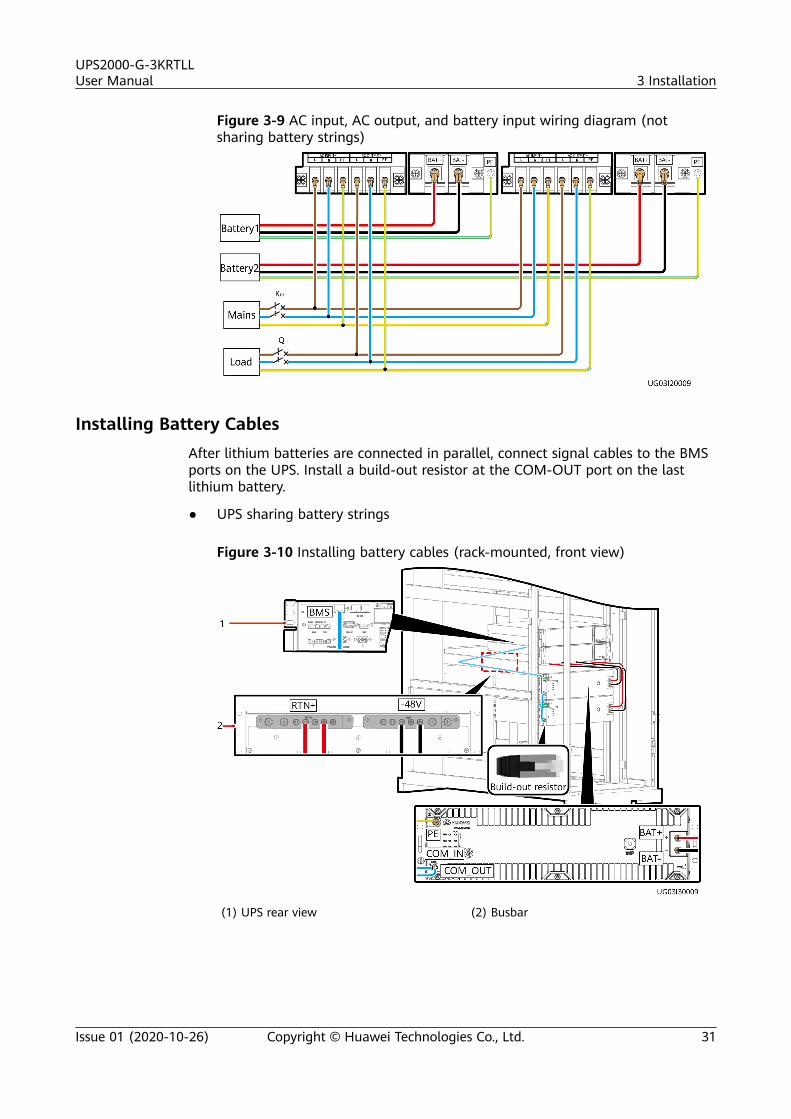
Figure 3-9 AC input, AC output, and battery input wiring diagram (notsharing battery strings)
Installing Battery CablesAfter lithium batteries are connected in parallel, connect signal cables to the BMSports on the UPS. Install a build-out resistor at the COM-OUT port on the lastlithium battery.
● UPS sharing battery strings
Figure 3-10 Installing battery cables (rack-mounted, front view)
(1) UPS rear view (2) Busbar
UPS2000-G-3KRTLLUser Manual 3 Installation
Issue 01 (2020-10-26) Copyright © Huawei Technologies Co., Ltd. 31
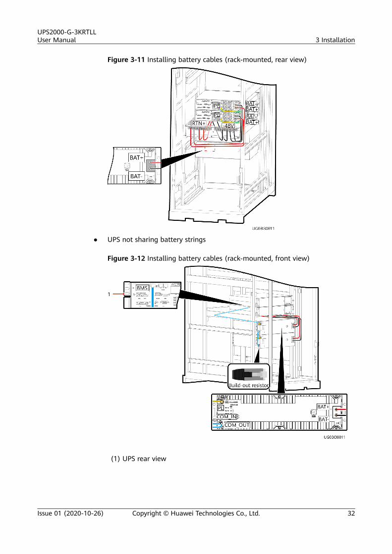
Figure 3-11 Installing battery cables (rack-mounted, rear view)
● UPS not sharing battery strings
Figure 3-12 Installing battery cables (rack-mounted, front view)
(1) UPS rear view
UPS2000-G-3KRTLLUser Manual 3 Installation
Issue 01 (2020-10-26) Copyright © Huawei Technologies Co., Ltd. 32
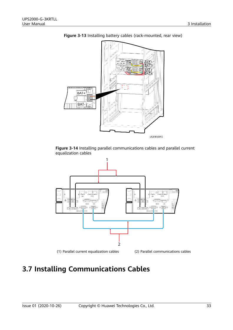
Figure 3-13 Installing battery cables (rack-mounted, rear view)
Figure 3-14 Installing parallel communications cables and parallel currentequalization cables
(1) Parallel current equalization cables (2) Parallel communications cables
3.7 Installing Communications Cables
UPS2000-G-3KRTLLUser Manual 3 Installation
Issue 01 (2020-10-26) Copyright © Huawei Technologies Co., Ltd. 33
NO TE
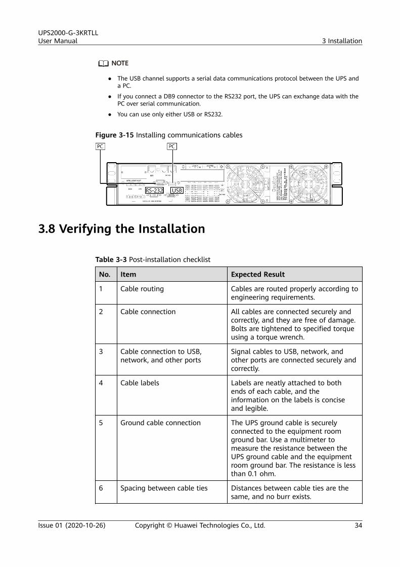
● The USB channel supports a serial data communications protocol between the UPS anda PC.
● If you connect a DB9 connector to the RS232 port, the UPS can exchange data with thePC over serial communication.
● You can use only either USB or RS232.
Figure 3-15 Installing communications cables
3.8 Verifying the Installation
Table 3-3 Post-installation checklist
No. Item Expected Result
1 Cable routing Cables are routed properly according toengineering requirements.
2 Cable connection All cables are connected securely andcorrectly, and they are free of damage.Bolts are tightened to specified torqueusing a torque wrench.
3 Cable connection to USB,network, and other ports
Signal cables to USB, network, andother ports are connected securely andcorrectly.
4 Cable labels Labels are neatly attached to bothends of each cable, and theinformation on the labels is conciseand legible.
5 Ground cable connection The UPS ground cable is securelyconnected to the equipment roomground bar. Use a multimeter tomeasure the resistance between theUPS ground cable and the equipmentroom ground bar. The resistance is lessthan 0.1 ohm.
6 Spacing between cable ties Distances between cable ties are thesame, and no burr exists.
UPS2000-G-3KRTLLUser Manual 3 Installation
Issue 01 (2020-10-26) Copyright © Huawei Technologies Co., Ltd. 34
No. Item Expected Result
7 Operating environment The inside and outside of the cabinetare free from conductive dust or othersundries.
UPS2000-G-3KRTLLUser Manual 3 Installation
Issue 01 (2020-10-26) Copyright © Huawei Technologies Co., Ltd. 35
4 Control Panel
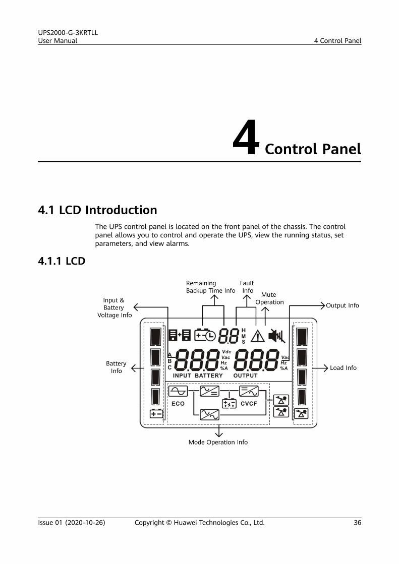
4.1 LCD IntroductionThe UPS control panel is located on the front panel of the chassis. The controlpanel allows you to control and operate the UPS, view the running status, setparameters, and view alarms.
4.1.1 LCD
UPS2000-G-3KRTLLUser Manual 4 Control Panel
Issue 01 (2020-10-26) Copyright © Huawei Technologies Co., Ltd. 36
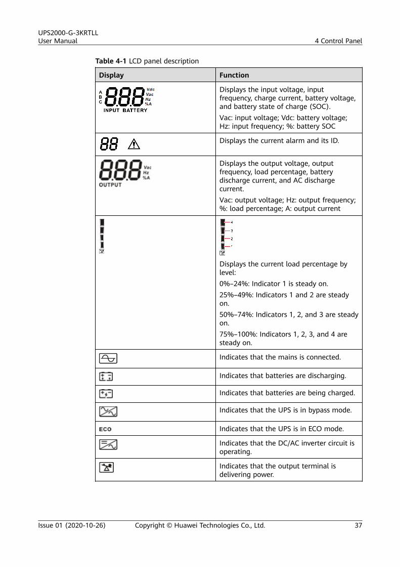
Table 4-1 LCD panel description
Display Function
Displays the input voltage, inputfrequency, charge current, battery voltage,and battery state of charge (SOC).Vac: input voltage; Vdc: battery voltage;Hz: input frequency; %: battery SOC
Displays the current alarm and its ID.
Displays the output voltage, outputfrequency, load percentage, batterydischarge current, and AC dischargecurrent.Vac: output voltage; Hz: output frequency;%: load percentage; A: output current
Displays the current load percentage bylevel:0%–24%: Indicator 1 is steady on.25%–49%: Indicators 1 and 2 are steadyon.50%–74%: Indicators 1, 2, and 3 are steadyon.75%–100%: Indicators 1, 2, 3, and 4 aresteady on.
Indicates that the mains is connected.
Indicates that batteries are discharging.
Indicates that batteries are being charged.
Indicates that the UPS is in bypass mode.
Indicates that the UPS is in ECO mode.
Indicates that the DC/AC inverter circuit isoperating.
Indicates that the output terminal isdelivering power.
UPS2000-G-3KRTLLUser Manual 4 Control Panel
Issue 01 (2020-10-26) Copyright © Huawei Technologies Co., Ltd. 37
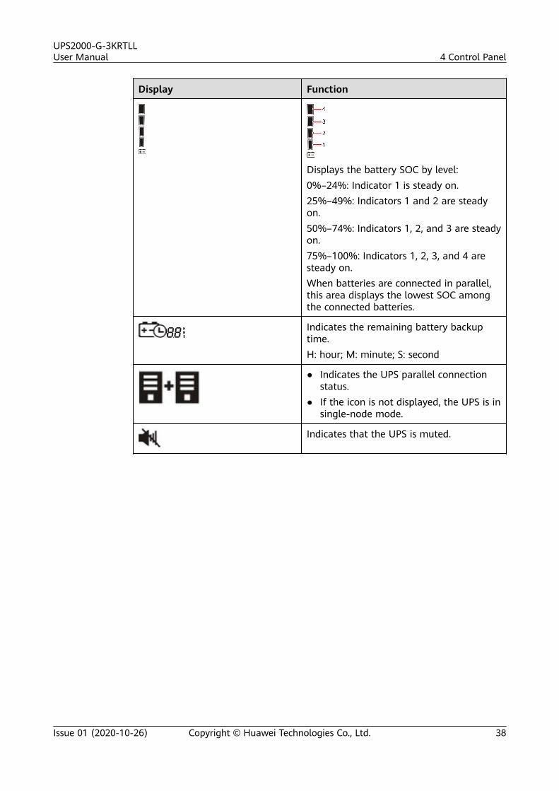
Display Function
Displays the battery SOC by level:0%–24%: Indicator 1 is steady on.25%–49%: Indicators 1 and 2 are steadyon.50%–74%: Indicators 1, 2, and 3 are steadyon.75%–100%: Indicators 1, 2, 3, and 4 aresteady on.When batteries are connected in parallel,this area displays the lowest SOC amongthe connected batteries.
Indicates the remaining battery backuptime.H: hour; M: minute; S: second
● Indicates the UPS parallel connectionstatus.
● If the icon is not displayed, the UPS is insingle-node mode.
Indicates that the UPS is muted.
UPS2000-G-3KRTLLUser Manual 4 Control Panel
Issue 01 (2020-10-26) Copyright © Huawei Technologies Co., Ltd. 38
4.1.2 Buttons
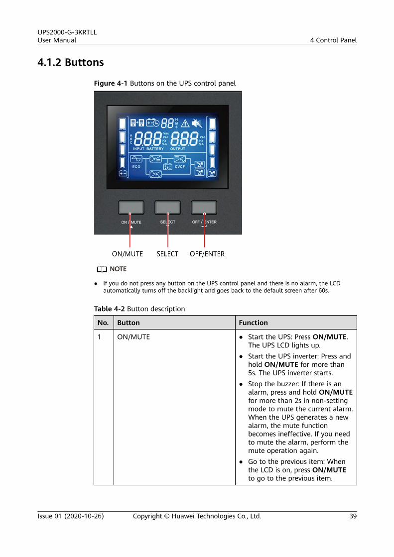
Figure 4-1 Buttons on the UPS control panel
NO TE
● If you do not press any button on the UPS control panel and there is no alarm, the LCDautomatically turns off the backlight and goes back to the default screen after 60s.
Table 4-2 Button description
No. Button Function
1 ON/MUTE ● Start the UPS: Press ON/MUTE.The UPS LCD lights up.
● Start the UPS inverter: Press andhold ON/MUTE for more than5s. The UPS inverter starts.
● Stop the buzzer: If there is analarm, press and hold ON/MUTEfor more than 2s in non-settingmode to mute the current alarm.When the UPS generates a newalarm, the mute functionbecomes ineffective. If you needto mute the alarm, perform themute operation again.
● Go to the previous item: Whenthe LCD is on, press ON/MUTEto go to the previous item.
UPS2000-G-3KRTLLUser Manual 4 Control Panel
Issue 01 (2020-10-26) Copyright © Huawei Technologies Co., Ltd. 39
No. Button Function
2 SELECT ● Go to the next item: PressSELECT in setting mode to go tothe next item.
● Go to the setting screen: Pressand hold SELECT for 1s on anon-setting screen.
3 OFF/ENTER ● Shut down the UPS: Press andhold OFF/ENTER for more than5s. The UPS inverter shuts down.The UPS transfers to bypassmode when the mains isavailable.
● Confirm: In UPS setting mode,press OFF/ENTER to confirmselection.
4 ON/MUTE+SELECT+OFF/ENTER Restore the initial password: Pressand hold ON/MUTE, SELECT, andOFF/ENTER at the same time for3s on the password login screen.
5 ON/MUTE+SELECT Exit: Press ON/MUTE and SELECTat the same time to exit the currentscreen (go to the upper-level menufrom the setting screen or go to thedefault screen from the selectionscreen).
4.1.3 LCD Screen Information
You can press SELECT to switch the information displayed on the LCD in sequence.The information is displayed in the following sequence: input voltage, inputfrequency, charge current, battery voltage, output voltage, output frequency, loadpercentage, DC discharge current, battery SOH, battery SOC, AC discharge current,and CPU version.
UPS2000-G-3KRTLLUser Manual 4 Control Panel
Issue 01 (2020-10-26) Copyright © Huawei Technologies Co., Ltd. 40
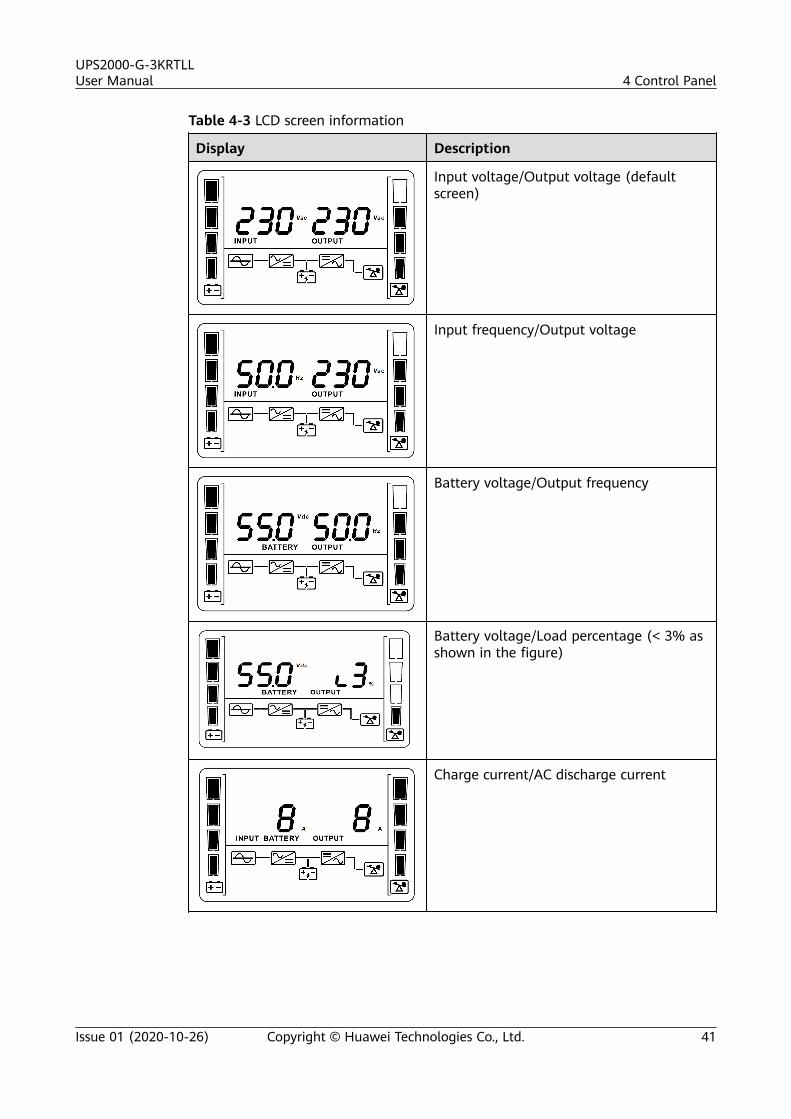
Table 4-3 LCD screen information
Display Description
Input voltage/Output voltage (defaultscreen)
Input frequency/Output voltage
Battery voltage/Output frequency
Battery voltage/Load percentage (< 3% asshown in the figure)
Charge current/AC discharge current
UPS2000-G-3KRTLLUser Manual 4 Control Panel
Issue 01 (2020-10-26) Copyright © Huawei Technologies Co., Ltd. 41
Display Description
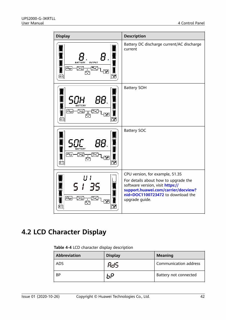
Battery DC discharge current/AC dischargecurrent
Battery SOH
Battery SOC
CPU version, for example, 51.35For details about how to upgrade thesoftware version, visit https://support.huawei.com/carrier/docview?nid=DOC1100723472 to download theupgrade guide.
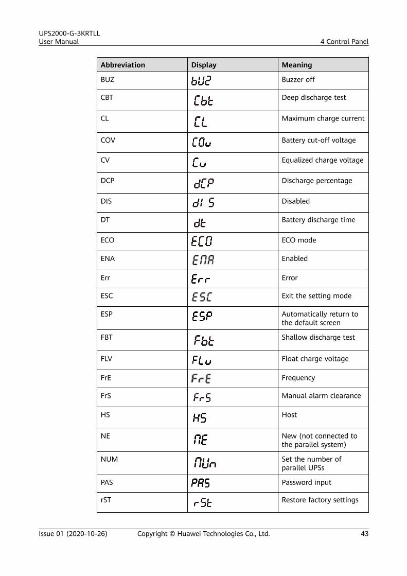
4.2 LCD Character Display
Table 4-4 LCD character display description
Abbreviation Display Meaning
ADS Communication address
BP Battery not connected
UPS2000-G-3KRTLLUser Manual 4 Control Panel
Issue 01 (2020-10-26) Copyright © Huawei Technologies Co., Ltd. 42
Abbreviation Display Meaning
BUZ Buzzer off
CBT Deep discharge test
CL Maximum charge current
COV Battery cut-off voltage
CV Equalized charge voltage
DCP Discharge percentage
DIS Disabled
DT Battery discharge time
ECO ECO mode
ENA Enabled
Err Error
ESC Exit the setting mode
ESP Automatically return tothe default screen
FBT Shallow discharge test
FLV Float charge voltage
FrE Frequency
FrS Manual alarm clearance
HS Host
NE New (not connected tothe parallel system)
NUM Set the number ofparallel UPSs
PAS Password input
rST Restore factory settings
UPS2000-G-3KRTLLUser Manual 4 Control Panel
Issue 01 (2020-10-26) Copyright © Huawei Technologies Co., Ltd. 43
Abbreviation Display Meaning
SBT Battery string sharing
SL Slave
VOT Voltage
< Less-than sign
4.3 Parameter SettingsPress and hold SELECT for 1s on a non-setting screen to access the login screenfor parameter settings. The initial password is 000001. Enter the correct passwordto access the UPS setting mode. Press SELECT to select a parameter, and thenpress OFF/ENTER to confirm the setting.
If you forgot the password, press and hold ON/MUTE, SELECT, and OFF/ENTER atthe same time for 3s on the password login screen to reset the password.
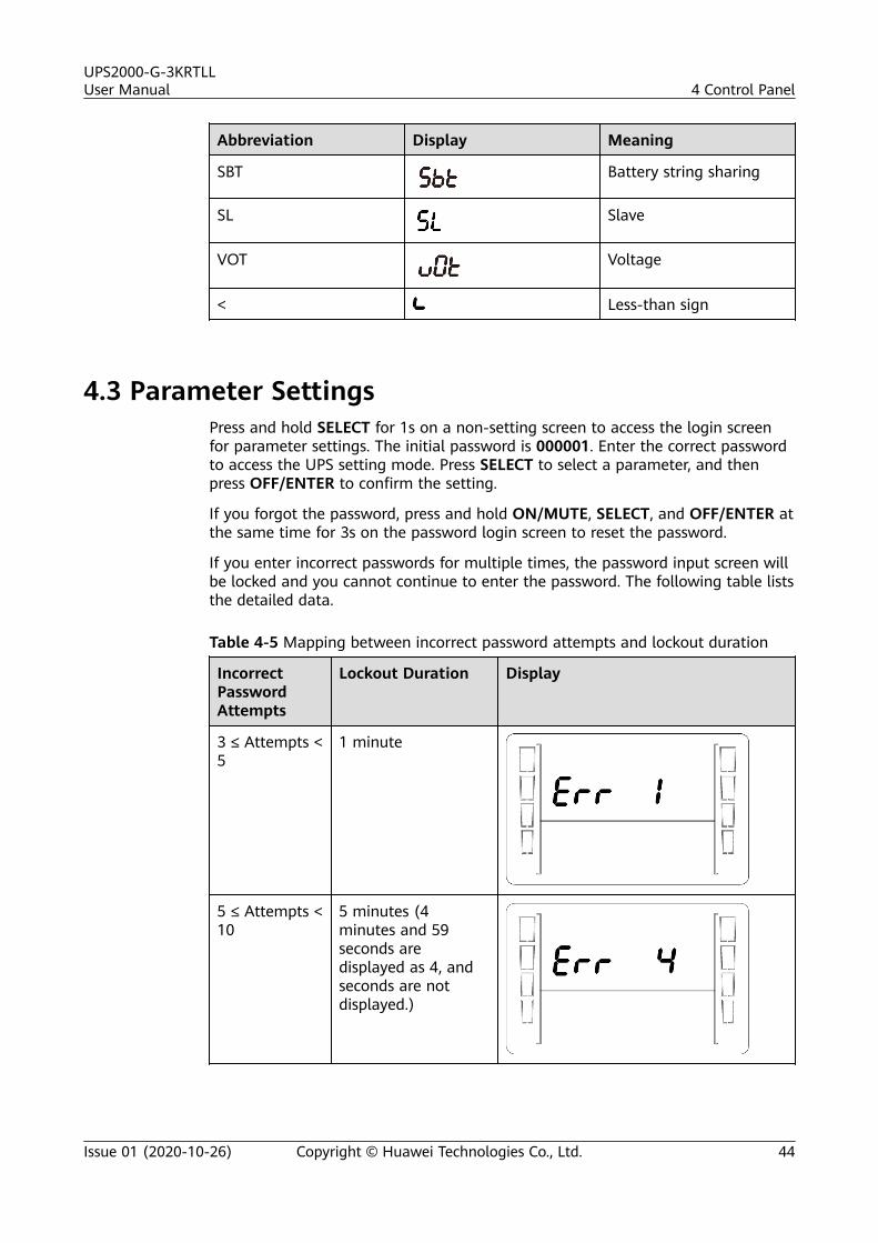
If you enter incorrect passwords for multiple times, the password input screen willbe locked and you cannot continue to enter the password. The following table liststhe detailed data.
Table 4-5 Mapping between incorrect password attempts and lockout duration
IncorrectPasswordAttempts
Lockout Duration Display
3 ≤ Attempts <5
1 minute
5 ≤ Attempts <10
5 minutes (4minutes and 59seconds aredisplayed as 4, andseconds are notdisplayed.)
UPS2000-G-3KRTLLUser Manual 4 Control Panel
Issue 01 (2020-10-26) Copyright © Huawei Technologies Co., Ltd. 44
IncorrectPasswordAttempts
Lockout Duration Display
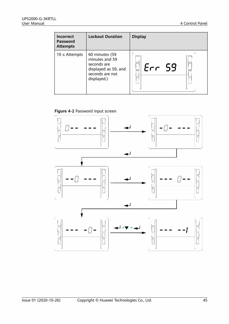
10 ≤ Attempts 60 minutes (59minutes and 59seconds aredisplayed as 59, andseconds are notdisplayed.)
Figure 4-2 Password input screen
UPS2000-G-3KRTLLUser Manual 4 Control Panel
Issue 01 (2020-10-26) Copyright © Huawei Technologies Co., Ltd. 45
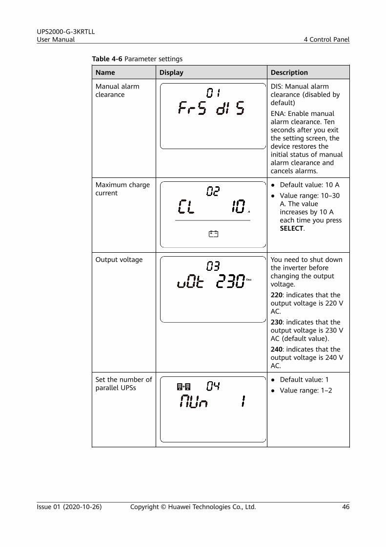
Table 4-6 Parameter settings
Name Display Description
Manual alarmclearance
DIS: Manual alarmclearance (disabled bydefault)ENA: Enable manualalarm clearance. Tenseconds after you exitthe setting screen, thedevice restores theinitial status of manualalarm clearance andcancels alarms.
Maximum chargecurrent
● Default value: 10 A● Value range: 10–30
A. The valueincreases by 10 Aeach time you pressSELECT.
Output voltage You need to shut downthe inverter beforechanging the outputvoltage.220: indicates that theoutput voltage is 220 VAC.230: indicates that theoutput voltage is 230 VAC (default value).240: indicates that theoutput voltage is 240 VAC.
Set the number ofparallel UPSs
● Default value: 1● Value range: 1–2
UPS2000-G-3KRTLLUser Manual 4 Control Panel
Issue 01 (2020-10-26) Copyright © Huawei Technologies Co., Ltd. 46
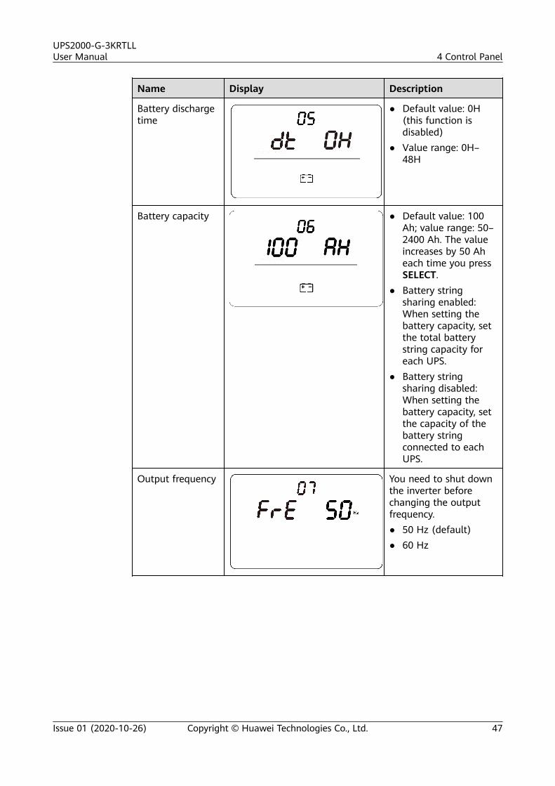
Name Display Description
Battery dischargetime
● Default value: 0H(this function isdisabled)
● Value range: 0H–48H
Battery capacity ● Default value: 100Ah; value range: 50–2400 Ah. The valueincreases by 50 Aheach time you pressSELECT.
● Battery stringsharing enabled:When setting thebattery capacity, setthe total batterystring capacity foreach UPS.
● Battery stringsharing disabled:When setting thebattery capacity, setthe capacity of thebattery stringconnected to eachUPS.
Output frequency You need to shut downthe inverter beforechanging the outputfrequency.● 50 Hz (default)● 60 Hz
UPS2000-G-3KRTLLUser Manual 4 Control Panel
Issue 01 (2020-10-26) Copyright © Huawei Technologies Co., Ltd. 47
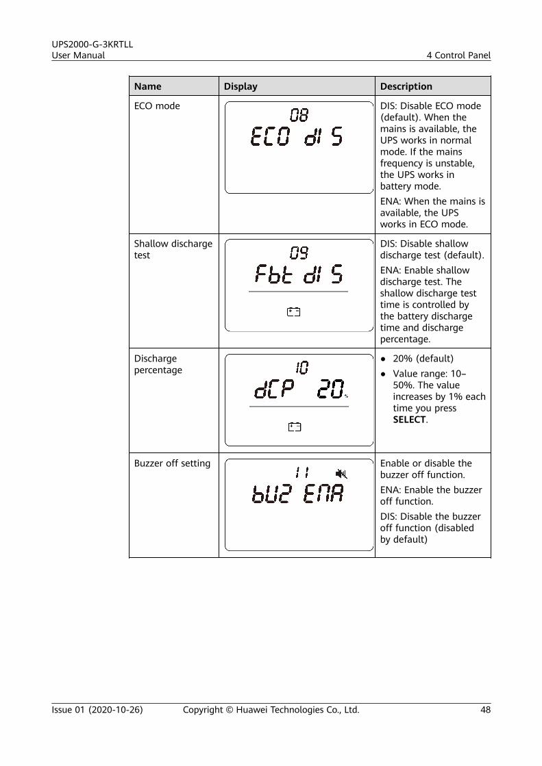
Name Display Description
ECO mode DIS: Disable ECO mode(default). When themains is available, theUPS works in normalmode. If the mainsfrequency is unstable,the UPS works inbattery mode.ENA: When the mains isavailable, the UPSworks in ECO mode.
Shallow dischargetest
DIS: Disable shallowdischarge test (default).ENA: Enable shallowdischarge test. Theshallow discharge testtime is controlled bythe battery dischargetime and dischargepercentage.
Dischargepercentage
● 20% (default)● Value range: 10–
50%. The valueincreases by 1% eachtime you pressSELECT.
Buzzer off setting Enable or disable thebuzzer off function.ENA: Enable the buzzeroff function.DIS: Disable the buzzeroff function (disabledby default)
UPS2000-G-3KRTLLUser Manual 4 Control Panel
Issue 01 (2020-10-26) Copyright © Huawei Technologies Co., Ltd. 48
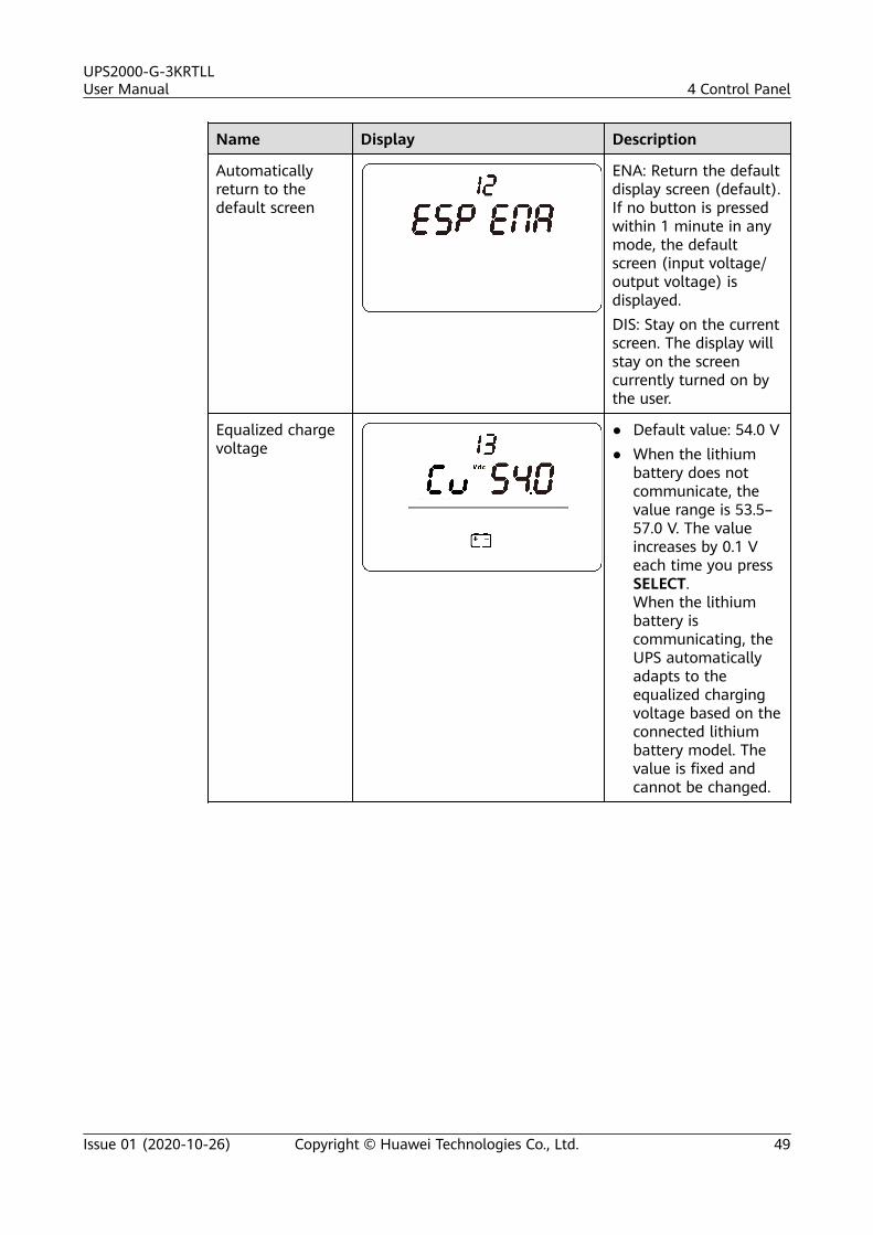
Name Display Description
Automaticallyreturn to thedefault screen
ENA: Return the defaultdisplay screen (default).If no button is pressedwithin 1 minute in anymode, the defaultscreen (input voltage/output voltage) isdisplayed.DIS: Stay on the currentscreen. The display willstay on the screencurrently turned on bythe user.
Equalized chargevoltage
● Default value: 54.0 V● When the lithium
battery does notcommunicate, thevalue range is 53.5–57.0 V. The valueincreases by 0.1 Veach time you pressSELECT.When the lithiumbattery iscommunicating, theUPS automaticallyadapts to theequalized chargingvoltage based on theconnected lithiumbattery model. Thevalue is fixed andcannot be changed.
UPS2000-G-3KRTLLUser Manual 4 Control Panel
Issue 01 (2020-10-26) Copyright © Huawei Technologies Co., Ltd. 49
Name Display Description
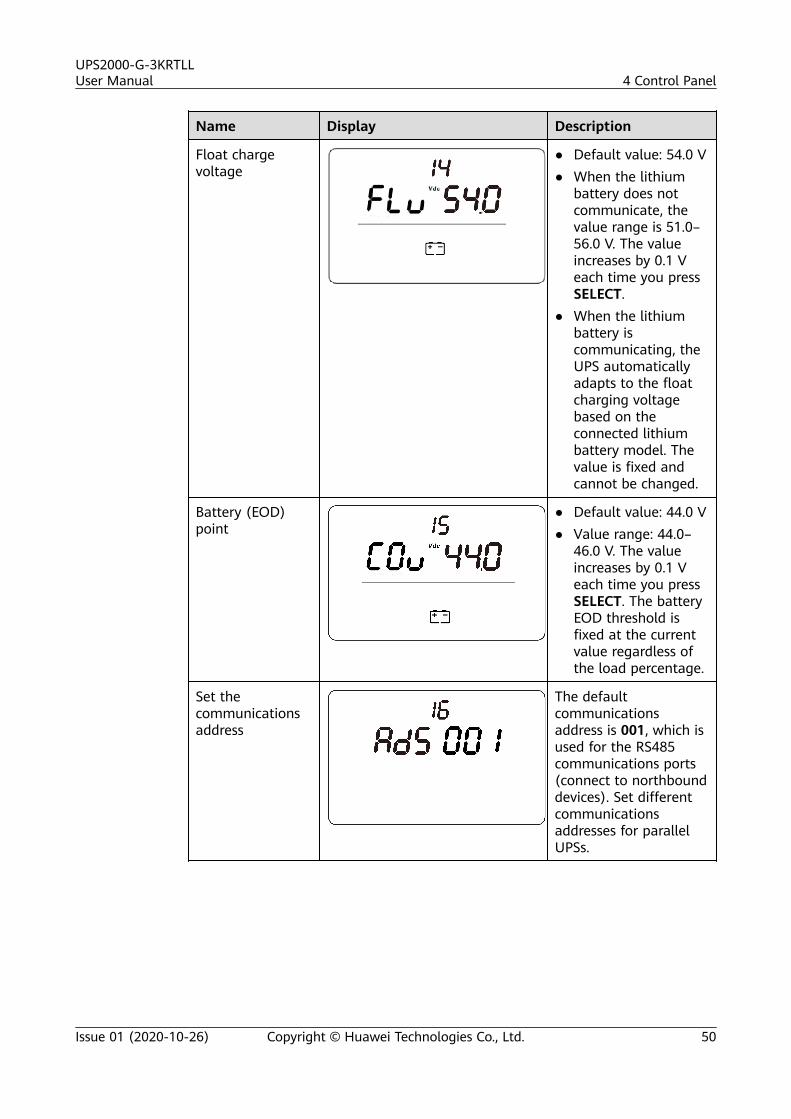
Float chargevoltage
● Default value: 54.0 V● When the lithium
battery does notcommunicate, thevalue range is 51.0–56.0 V. The valueincreases by 0.1 Veach time you pressSELECT.
● When the lithiumbattery iscommunicating, theUPS automaticallyadapts to the floatcharging voltagebased on theconnected lithiumbattery model. Thevalue is fixed andcannot be changed.
Battery (EOD)point
● Default value: 44.0 V● Value range: 44.0–
46.0 V. The valueincreases by 0.1 Veach time you pressSELECT. The batteryEOD threshold isfixed at the currentvalue regardless ofthe load percentage.
Set thecommunicationsaddress
The defaultcommunicationsaddress is 001, which isused for the RS485communications ports(connect to northbounddevices). Set differentcommunicationsaddresses for parallelUPSs.
UPS2000-G-3KRTLLUser Manual 4 Control Panel
Issue 01 (2020-10-26) Copyright © Huawei Technologies Co., Ltd. 50
Name Display Description
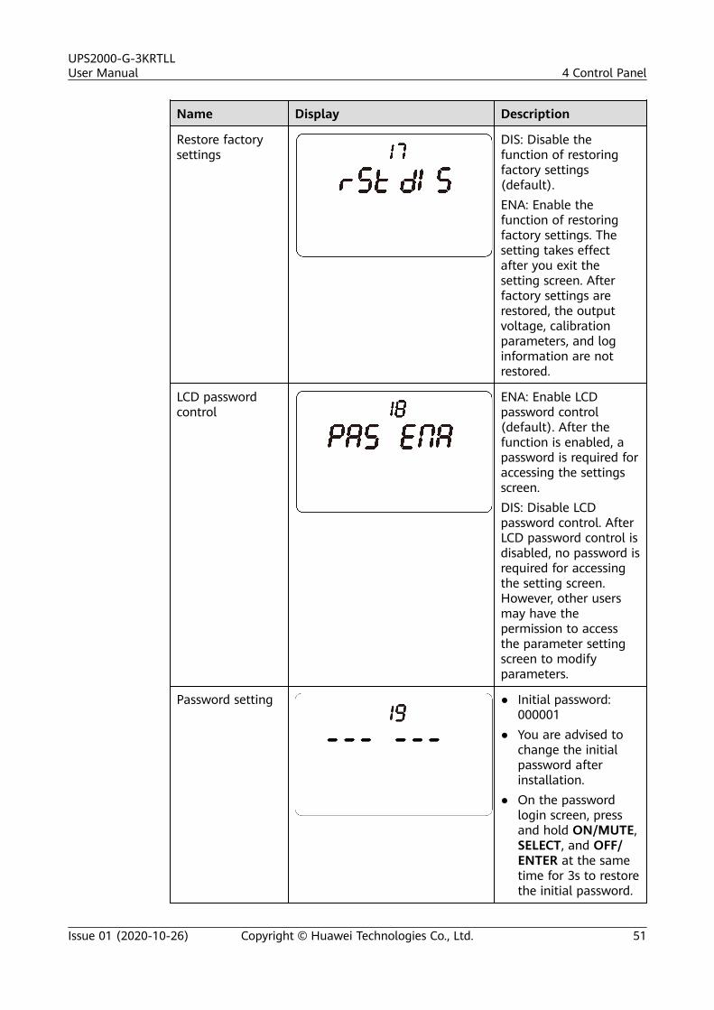
Restore factorysettings
DIS: Disable thefunction of restoringfactory settings(default).ENA: Enable thefunction of restoringfactory settings. Thesetting takes effectafter you exit thesetting screen. Afterfactory settings arerestored, the outputvoltage, calibrationparameters, and loginformation are notrestored.
LCD passwordcontrol
ENA: Enable LCDpassword control(default). After thefunction is enabled, apassword is required foraccessing the settingsscreen.DIS: Disable LCDpassword control. AfterLCD password control isdisabled, no password isrequired for accessingthe setting screen.However, other usersmay have thepermission to accessthe parameter settingscreen to modifyparameters.
Password setting ● Initial password:000001
● You are advised tochange the initialpassword afterinstallation.
● On the passwordlogin screen, pressand hold ON/MUTE,SELECT, and OFF/ENTER at the sametime for 3s to restorethe initial password.
UPS2000-G-3KRTLLUser Manual 4 Control Panel
Issue 01 (2020-10-26) Copyright © Huawei Technologies Co., Ltd. 51
Name Display Description
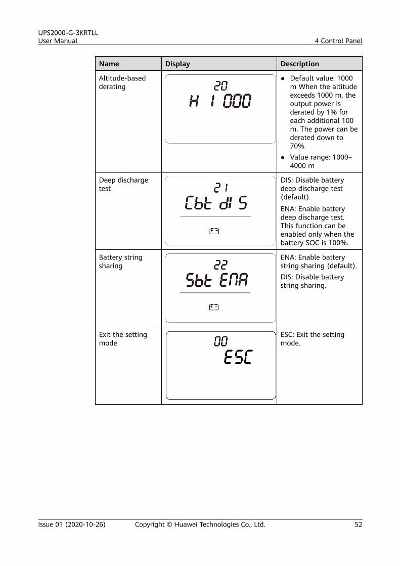
Altitude-basedderating
● Default value: 1000m When the altitudeexceeds 1000 m, theoutput power isderated by 1% foreach additional 100m. The power can bederated down to70%.
● Value range: 1000–4000 m
Deep dischargetest
DIS: Disable batterydeep discharge test(default).
ENA: Enable batterydeep discharge test.This function can beenabled only when thebattery SOC is 100%.
Battery stringsharing
ENA: Enable batterystring sharing (default).DIS: Disable batterystring sharing.
Exit the settingmode
ESC: Exit the settingmode.
UPS2000-G-3KRTLLUser Manual 4 Control Panel
Issue 01 (2020-10-26) Copyright © Huawei Technologies Co., Ltd. 52
4.4 Operating Modes
NO TICE
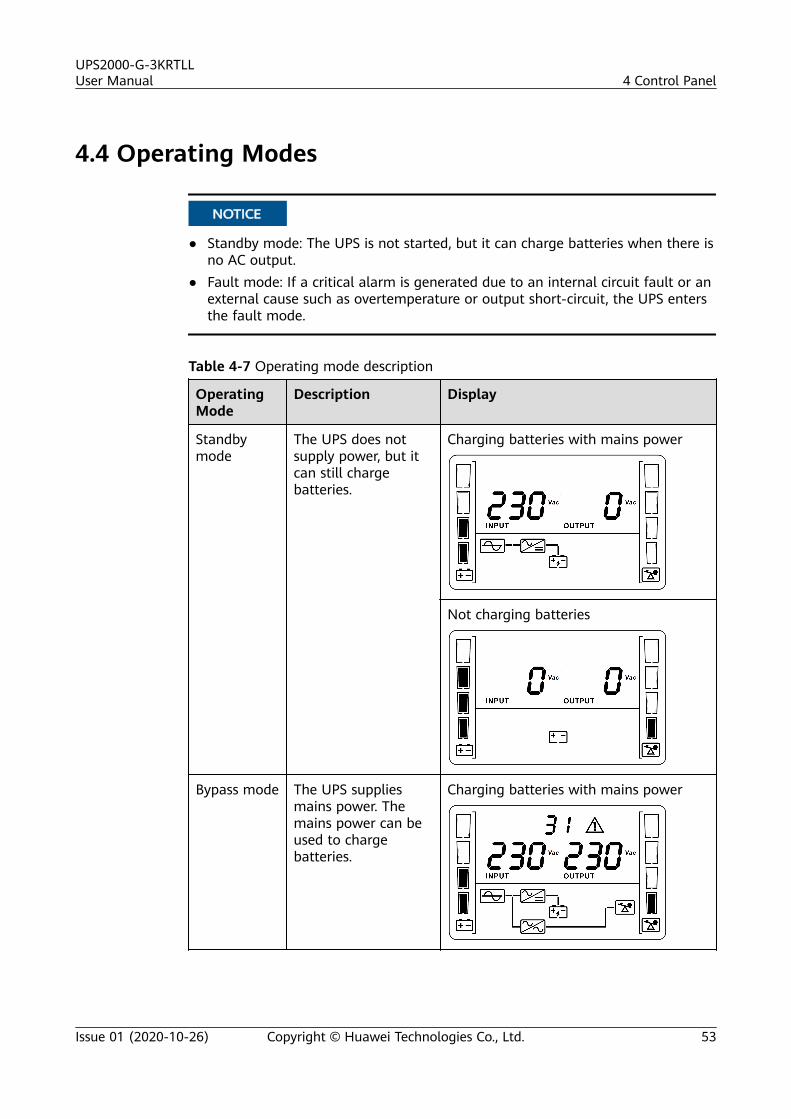
● Standby mode: The UPS is not started, but it can charge batteries when there isno AC output.
● Fault mode: If a critical alarm is generated due to an internal circuit fault or anexternal cause such as overtemperature or output short-circuit, the UPS entersthe fault mode.
Table 4-7 Operating mode description
OperatingMode
Description Display
Standbymode
The UPS does notsupply power, but itcan still chargebatteries.
Charging batteries with mains power
Not charging batteries
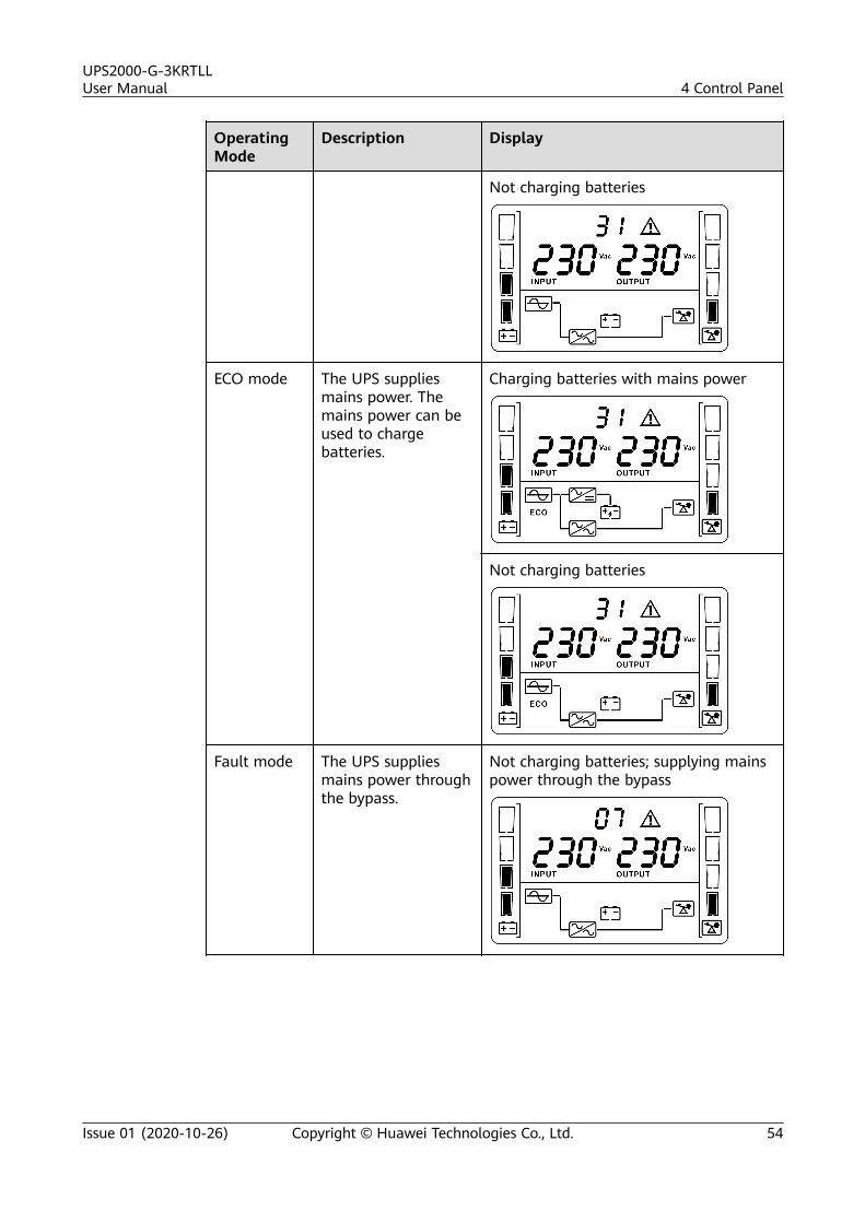
Bypass mode The UPS suppliesmains power. Themains power can beused to chargebatteries.
Charging batteries with mains power
UPS2000-G-3KRTLLUser Manual 4 Control Panel
Issue 01 (2020-10-26) Copyright © Huawei Technologies Co., Ltd. 53
OperatingMode
Description Display
Not charging batteries
ECO mode The UPS suppliesmains power. Themains power can beused to chargebatteries.
Charging batteries with mains power
Not charging batteries
Fault mode The UPS suppliesmains power throughthe bypass.
Not charging batteries; supplying mainspower through the bypass
UPS2000-G-3KRTLLUser Manual 4 Control Panel
Issue 01 (2020-10-26) Copyright © Huawei Technologies Co., Ltd. 54
OperatingMode
Description Display
Not charging batteries
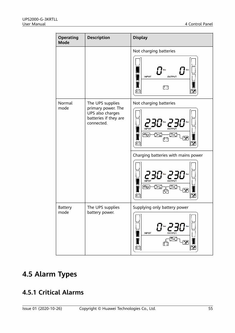
Normalmode
The UPS suppliesprimary power. TheUPS also chargesbatteries if they areconnected.
Not charging batteries
Charging batteries with mains power
Batterymode
The UPS suppliesbattery power.
Supplying only battery power
4.5 Alarm Types
4.5.1 Critical Alarms
UPS2000-G-3KRTLLUser Manual 4 Control Panel
Issue 01 (2020-10-26) Copyright © Huawei Technologies Co., Ltd. 55
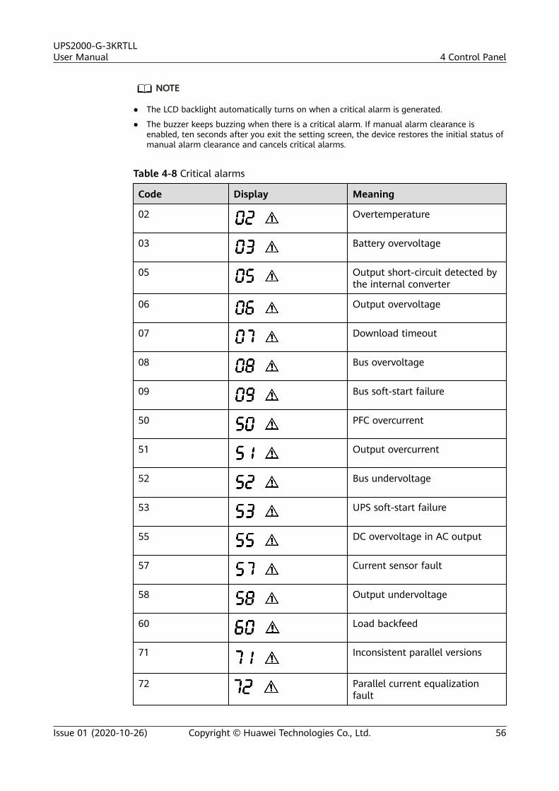
NO TE
● The LCD backlight automatically turns on when a critical alarm is generated.
● The buzzer keeps buzzing when there is a critical alarm. If manual alarm clearance isenabled, ten seconds after you exit the setting screen, the device restores the initial status ofmanual alarm clearance and cancels critical alarms.
Table 4-8 Critical alarms
Code Display Meaning
02 Overtemperature
03 Battery overvoltage
05 Output short-circuit detected bythe internal converter
06 Output overvoltage
07 Download timeout
08 Bus overvoltage
09 Bus soft-start failure
50 PFC overcurrent
51 Output overcurrent
52 Bus undervoltage
53 UPS soft-start failure
55 DC overvoltage in AC output
57 Current sensor fault
58 Output undervoltage
60 Load backfeed
71 Inconsistent parallel versions
72 Parallel current equalizationfault
UPS2000-G-3KRTLLUser Manual 4 Control Panel
Issue 01 (2020-10-26) Copyright © Huawei Technologies Co., Ltd. 56
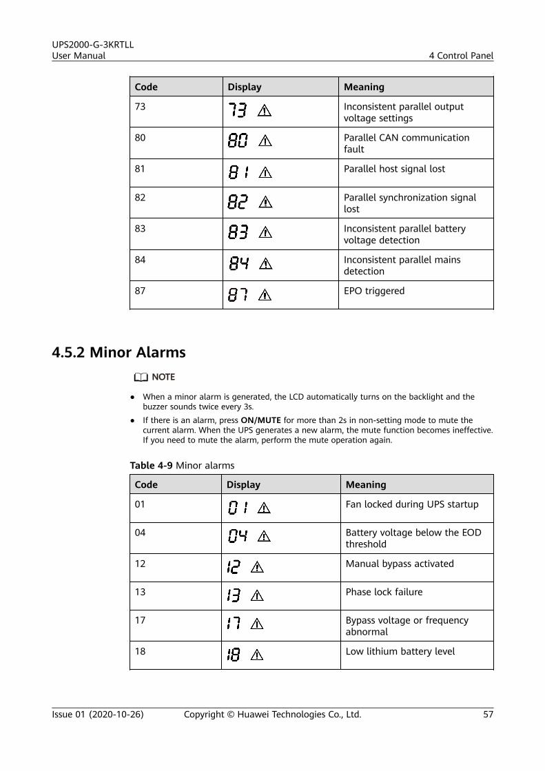
Code Display Meaning
73 Inconsistent parallel outputvoltage settings
80 Parallel CAN communicationfault
81 Parallel host signal lost
82 Parallel synchronization signallost
83 Inconsistent parallel batteryvoltage detection
84 Inconsistent parallel mainsdetection
87 EPO triggered
4.5.2 Minor AlarmsNO TE
● When a minor alarm is generated, the LCD automatically turns on the backlight and thebuzzer sounds twice every 3s.
● If there is an alarm, press ON/MUTE for more than 2s in non-setting mode to mute thecurrent alarm. When the UPS generates a new alarm, the mute function becomes ineffective.If you need to mute the alarm, perform the mute operation again.
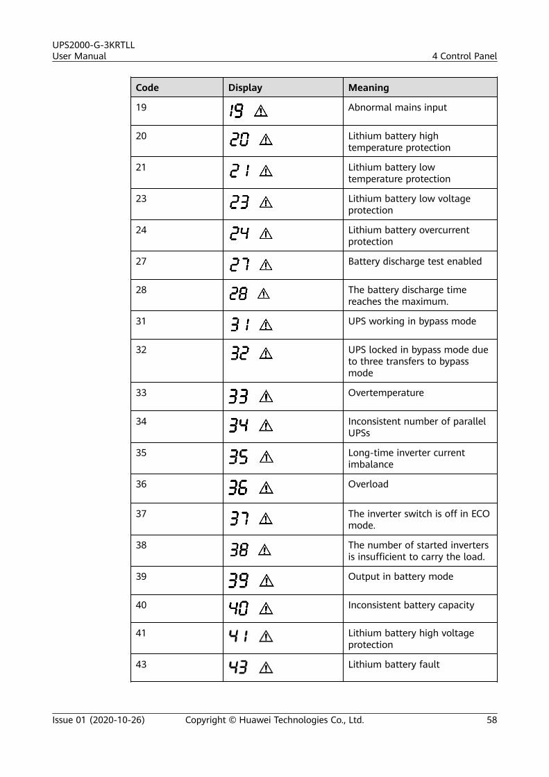
Table 4-9 Minor alarms
Code Display Meaning
01 Fan locked during UPS startup
04 Battery voltage below the EODthreshold
12 Manual bypass activated
13 Phase lock failure
17 Bypass voltage or frequencyabnormal
18 Low lithium battery level
UPS2000-G-3KRTLLUser Manual 4 Control Panel
Issue 01 (2020-10-26) Copyright © Huawei Technologies Co., Ltd. 57
Code Display Meaning
19 Abnormal mains input
20 Lithium battery hightemperature protection
21 Lithium battery lowtemperature protection
23 Lithium battery low voltageprotection
24 Lithium battery overcurrentprotection
27 Battery discharge test enabled
28 The battery discharge timereaches the maximum.
31 UPS working in bypass mode
32 UPS locked in bypass mode dueto three transfers to bypassmode
33 Overtemperature
34 Inconsistent number of parallelUPSs
35 Long-time inverter currentimbalance
36 Overload
37 The inverter switch is off in ECOmode.
38 The number of started invertersis insufficient to carry the load.
39 Output in battery mode
40 Inconsistent battery capacity
41 Lithium battery high voltageprotection
43 Lithium battery fault
UPS2000-G-3KRTLLUser Manual 4 Control Panel
Issue 01 (2020-10-26) Copyright © Huawei Technologies Co., Ltd. 58
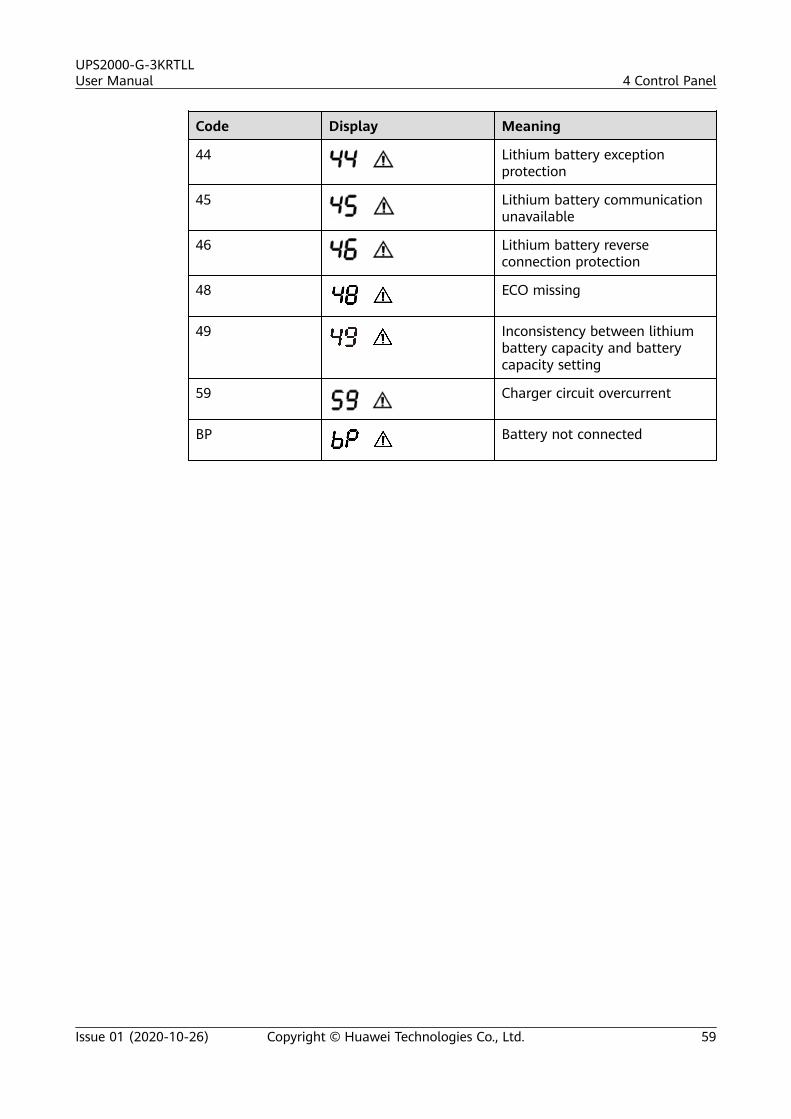
Code Display Meaning
44 Lithium battery exceptionprotection
45 Lithium battery communicationunavailable
46 Lithium battery reverseconnection protection
48 ECO missing
49 Inconsistency between lithiumbattery capacity and batterycapacity setting
59 Charger circuit overcurrent
BP Battery not connected
UPS2000-G-3KRTLLUser Manual 4 Control Panel
Issue 01 (2020-10-26) Copyright © Huawei Technologies Co., Ltd. 59
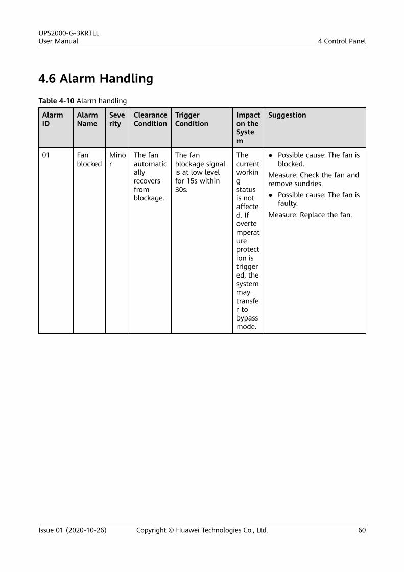
4.6 Alarm Handling
Table 4-10 Alarm handling
AlarmID
AlarmName
Severity
ClearanceCondition
TriggerCondition
Impacton theSystem
Suggestion
01 Fanblocked
Minor
The fanautomaticallyrecoversfromblockage.
The fanblockage signalis at low levelfor 15s within30s.
Thecurrentworkingstatusis notaffected. Ifovertemperatureprotection istriggered, thesystemmaytransfer tobypassmode.
● Possible cause: The fan isblocked.
Measure: Check the fan andremove sundries.● Possible cause: The fan is
faulty.Measure: Replace the fan.
UPS2000-G-3KRTLLUser Manual 4 Control Panel
Issue 01 (2020-10-26) Copyright © Huawei Technologies Co., Ltd. 60
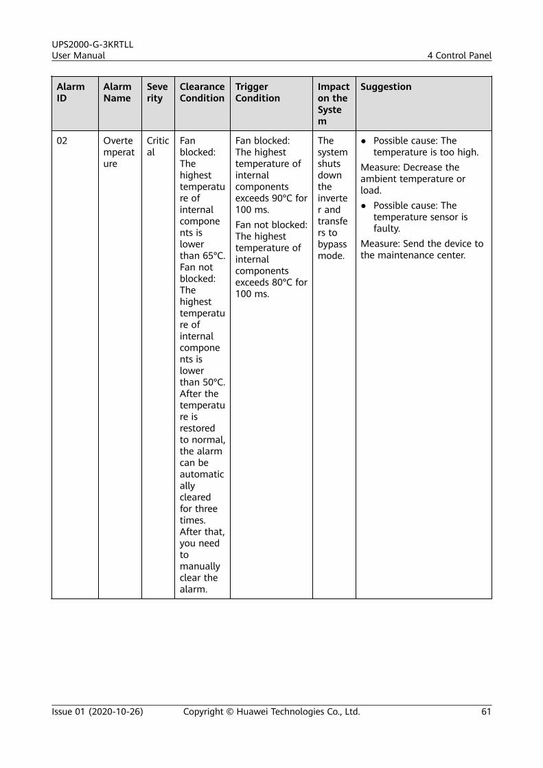
AlarmID
AlarmName
Severity
ClearanceCondition
TriggerCondition
Impacton theSystem
Suggestion
02 Overtemperature
Critical
Fanblocked:Thehighesttemperature ofinternalcomponents islowerthan 65°C.Fan notblocked:Thehighesttemperature ofinternalcomponents islowerthan 50°C.After thetemperature isrestoredto normal,the alarmcan beautomaticallyclearedfor threetimes.After that,you needtomanuallyclear thealarm.
Fan blocked:The highesttemperature ofinternalcomponentsexceeds 90°C for100 ms.Fan not blocked:The highesttemperature ofinternalcomponentsexceeds 80°C for100 ms.
Thesystemshutsdowntheinverter andtransfers tobypassmode.
● Possible cause: Thetemperature is too high.
Measure: Decrease theambient temperature orload.● Possible cause: The
temperature sensor isfaulty.
Measure: Send the device tothe maintenance center.
UPS2000-G-3KRTLLUser Manual 4 Control Panel
Issue 01 (2020-10-26) Copyright © Huawei Technologies Co., Ltd. 61
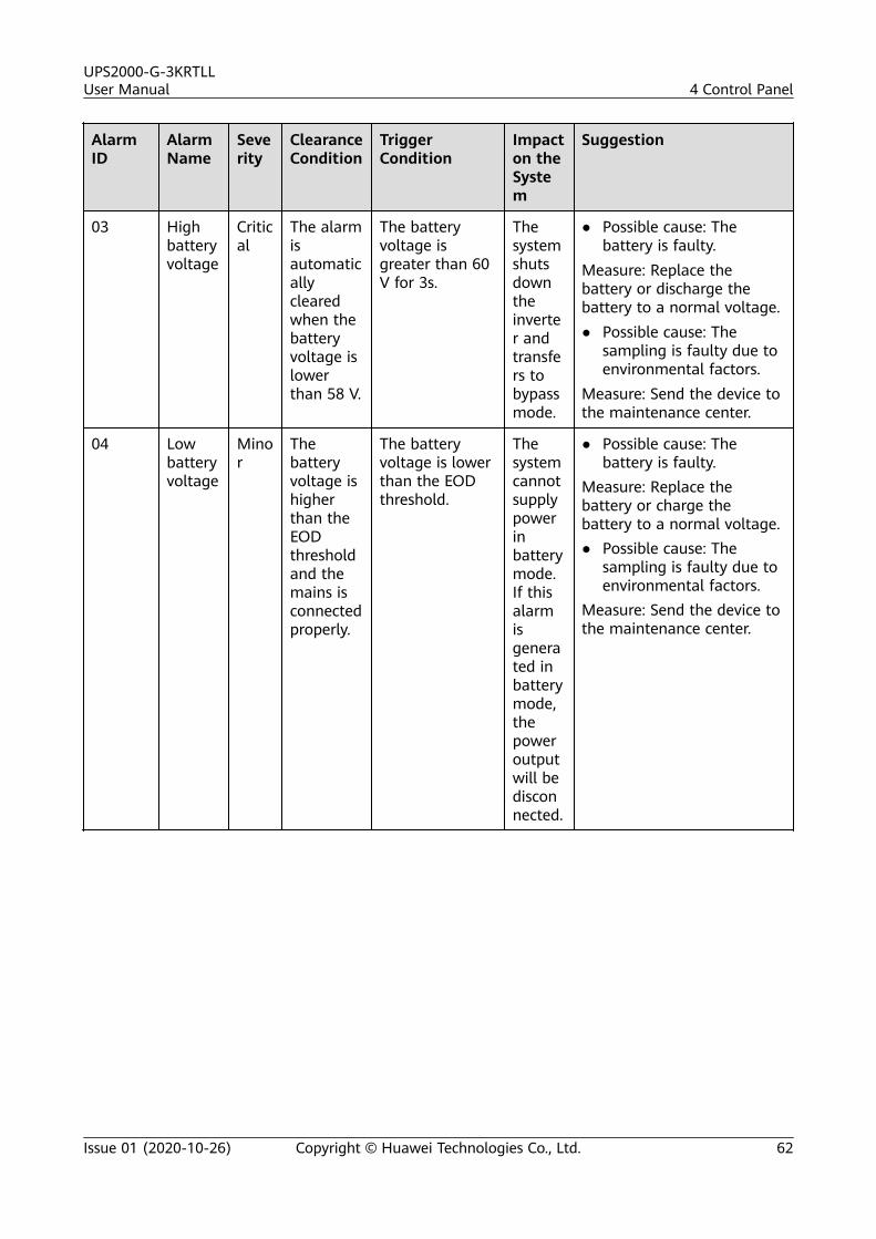
AlarmID
AlarmName
Severity
ClearanceCondition
TriggerCondition
Impacton theSystem
Suggestion
03 Highbatteryvoltage
Critical
The alarmisautomaticallyclearedwhen thebatteryvoltage islowerthan 58 V.
The batteryvoltage isgreater than 60V for 3s.
Thesystemshutsdowntheinverter andtransfers tobypassmode.
● Possible cause: Thebattery is faulty.
Measure: Replace thebattery or discharge thebattery to a normal voltage.● Possible cause: The
sampling is faulty due toenvironmental factors.
Measure: Send the device tothe maintenance center.
04 Lowbatteryvoltage
Minor
Thebatteryvoltage ishigherthan theEODthresholdand themains isconnectedproperly.
The batteryvoltage is lowerthan the EODthreshold.
Thesystemcannotsupplypowerinbatterymode.If thisalarmisgenerated inbatterymode,thepoweroutputwill bedisconnected.
● Possible cause: Thebattery is faulty.
Measure: Replace thebattery or charge thebattery to a normal voltage.● Possible cause: The
sampling is faulty due toenvironmental factors.
Measure: Send the device tothe maintenance center.
UPS2000-G-3KRTLLUser Manual 4 Control Panel
Issue 01 (2020-10-26) Copyright © Huawei Technologies Co., Ltd. 62
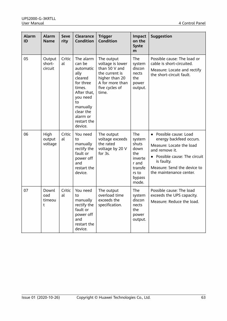
AlarmID
AlarmName
Severity
ClearanceCondition
TriggerCondition
Impacton theSystem
Suggestion
05 Outputshort-circuit
Critical
The alarmcan beautomaticallyclearedfor threetimes.After that,you needtomanuallyclear thealarm orrestart thedevice.
The outputvoltage is lowerthan 50 V andthe current ishigher than 20A for more thanfive cycles oftime.
Thesystemdisconnectsthepoweroutput.
Possible cause: The load orcable is short-circuited.Measure: Locate and rectifythe short-circuit fault.
06 Highoutputvoltage
Critical
You needtomanuallyrectify thefault orpower offandrestart thedevice.
The outputvoltage exceedsthe ratedvoltage by 20 Vfor 3s.
Thesystemshutsdowntheinverter andtransfers tobypassmode.
● Possible cause: Loadenergy backfeed occurs.
Measure: Locate the loadand remove it.● Possible cause: The circuit
is faulty.Measure: Send the device tothe maintenance center.
07 Downloadtimeout
Critical
You needtomanuallyrectify thefault orpower offandrestart thedevice.
The outputoverload timeexceeds thespecification.
Thesystemdisconnectsthepoweroutput.
Possible cause: The loadexceeds the UPS capacity.Measure: Reduce the load.
UPS2000-G-3KRTLLUser Manual 4 Control Panel
Issue 01 (2020-10-26) Copyright © Huawei Technologies Co., Ltd. 63
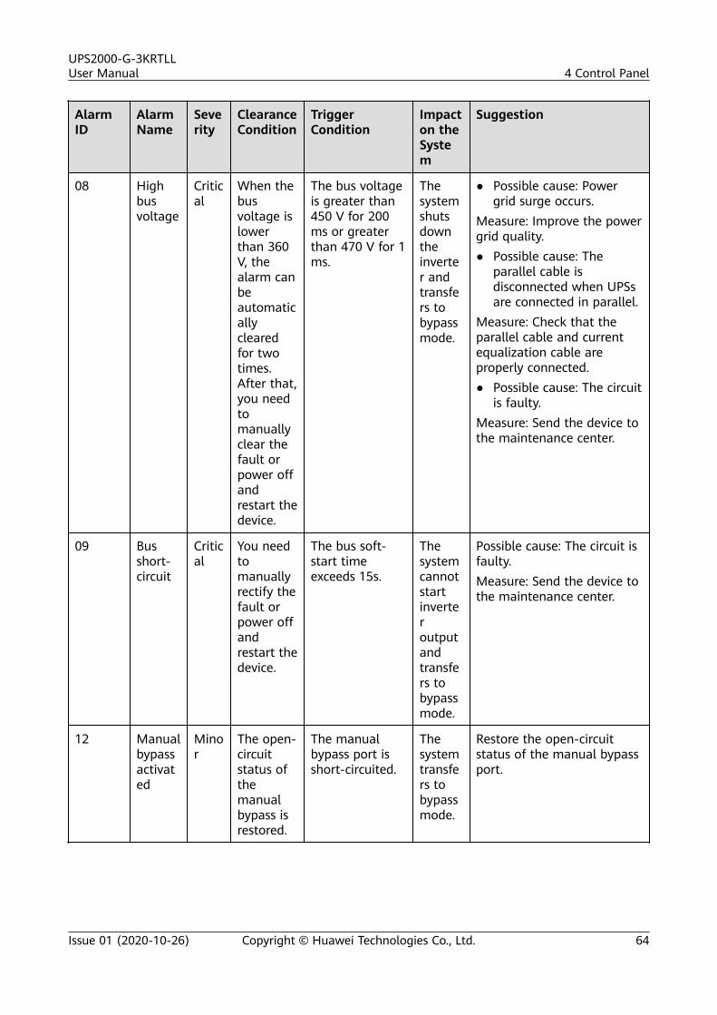
AlarmID
AlarmName
Severity
ClearanceCondition
TriggerCondition
Impacton theSystem
Suggestion
08 Highbusvoltage
Critical
When thebusvoltage islowerthan 360V, thealarm canbeautomaticallyclearedfor twotimes.After that,you needtomanuallyclear thefault orpower offandrestart thedevice.
The bus voltageis greater than450 V for 200ms or greaterthan 470 V for 1ms.
Thesystemshutsdowntheinverter andtransfers tobypassmode.
● Possible cause: Powergrid surge occurs.
Measure: Improve the powergrid quality.● Possible cause: The
parallel cable isdisconnected when UPSsare connected in parallel.
Measure: Check that theparallel cable and currentequalization cable areproperly connected.● Possible cause: The circuit
is faulty.Measure: Send the device tothe maintenance center.
09 Busshort-circuit
Critical
You needtomanuallyrectify thefault orpower offandrestart thedevice.
The bus soft-start timeexceeds 15s.
Thesystemcannotstartinverteroutputandtransfers tobypassmode.
Possible cause: The circuit isfaulty.Measure: Send the device tothe maintenance center.
12 Manualbypassactivated
Minor
The open-circuitstatus ofthemanualbypass isrestored.
The manualbypass port isshort-circuited.
Thesystemtransfers tobypassmode.
Restore the open-circuitstatus of the manual bypassport.
UPS2000-G-3KRTLLUser Manual 4 Control Panel
Issue 01 (2020-10-26) Copyright © Huawei Technologies Co., Ltd. 64
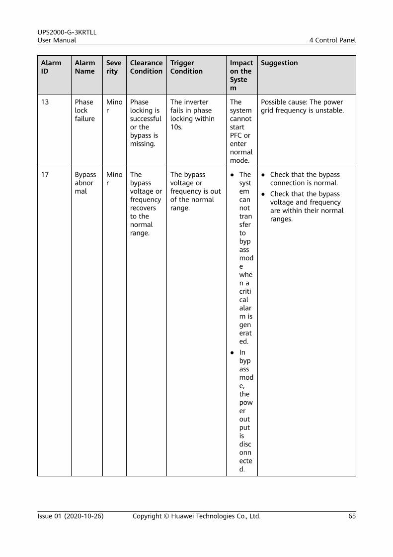
AlarmID
AlarmName
Severity
ClearanceCondition
TriggerCondition
Impacton theSystem
Suggestion
13 Phaselockfailure
Minor
Phaselocking issuccessfulor thebypass ismissing.
The inverterfails in phaselocking within10s.
ThesystemcannotstartPFC orenternormalmode.
Possible cause: The powergrid frequency is unstable.
17 Bypassabnormal
Minor
Thebypassvoltage orfrequencyrecoversto thenormalrange.
The bypassvoltage orfrequency is outof the normalrange.
● Thesystemcannottransfertobypassmodewhen acriticalalarm isgenerated.
● Inbypassmode,thepoweroutputisdisconnected.
● Check that the bypassconnection is normal.
● Check that the bypassvoltage and frequencyare within their normalranges.
UPS2000-G-3KRTLLUser Manual 4 Control Panel
Issue 01 (2020-10-26) Copyright © Huawei Technologies Co., Ltd. 65
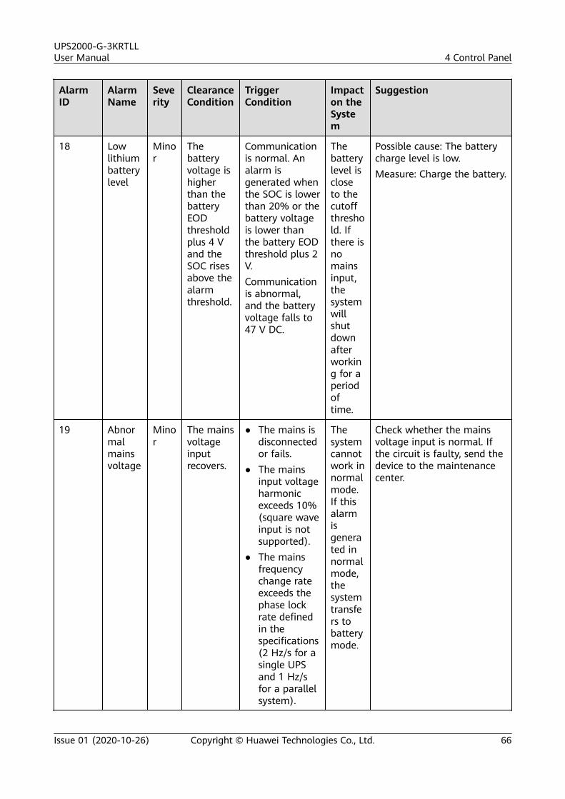
AlarmID
AlarmName
Severity
ClearanceCondition
TriggerCondition
Impacton theSystem
Suggestion
18 Lowlithiumbatterylevel
Minor
Thebatteryvoltage ishigherthan thebatteryEODthresholdplus 4 Vand theSOC risesabove thealarmthreshold.
Communicationis normal. Analarm isgenerated whenthe SOC is lowerthan 20% or thebattery voltageis lower thanthe battery EODthreshold plus 2V.Communicationis abnormal,and the batteryvoltage falls to47 V DC.
Thebatterylevel iscloseto thecutoffthreshold. Ifthere isnomainsinput,thesystemwillshutdownafterworking for aperiodoftime.
Possible cause: The batterycharge level is low.Measure: Charge the battery.
19 Abnormalmainsvoltage
Minor
The mainsvoltageinputrecovers.
● The mains isdisconnectedor fails.
● The mainsinput voltageharmonicexceeds 10%(square waveinput is notsupported).
● The mainsfrequencychange rateexceeds thephase lockrate definedin thespecifications(2 Hz/s for asingle UPSand 1 Hz/sfor a parallelsystem).
Thesystemcannotwork innormalmode.If thisalarmisgenerated innormalmode,thesystemtransfers tobatterymode.
Check whether the mainsvoltage input is normal. Ifthe circuit is faulty, send thedevice to the maintenancecenter.
UPS2000-G-3KRTLLUser Manual 4 Control Panel
Issue 01 (2020-10-26) Copyright © Huawei Technologies Co., Ltd. 66
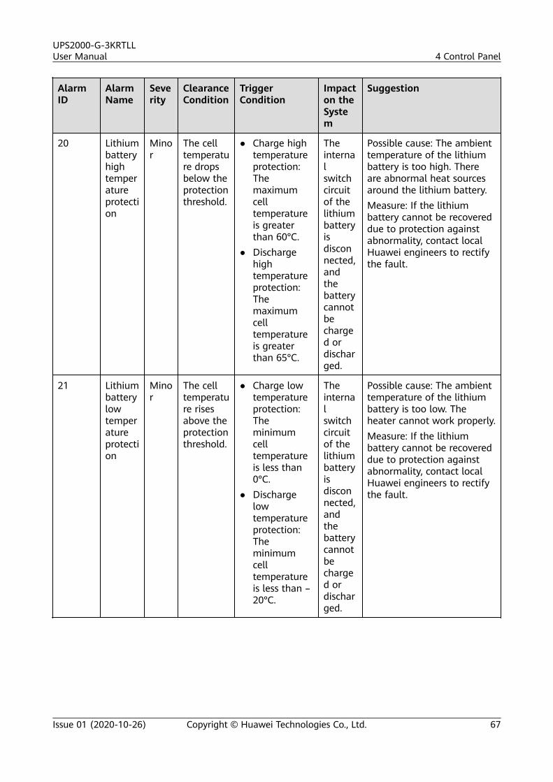
AlarmID
AlarmName
Severity
ClearanceCondition
TriggerCondition
Impacton theSystem
Suggestion
20 Lithiumbatteryhightemperatureprotection
Minor
The celltemperature dropsbelow theprotectionthreshold.
● Charge hightemperatureprotection:Themaximumcelltemperatureis greaterthan 60°C.
● Dischargehightemperatureprotection:Themaximumcelltemperatureis greaterthan 65°C.
Theinternalswitchcircuitof thelithiumbatteryisdisconnected,andthebatterycannotbecharged ordischarged.
Possible cause: The ambienttemperature of the lithiumbattery is too high. Thereare abnormal heat sourcesaround the lithium battery.Measure: If the lithiumbattery cannot be recovereddue to protection againstabnormality, contact localHuawei engineers to rectifythe fault.
21 Lithiumbatterylowtemperatureprotection
Minor
The celltemperature risesabove theprotectionthreshold.
● Charge lowtemperatureprotection:Theminimumcelltemperatureis less than0°C.
● Dischargelowtemperatureprotection:Theminimumcelltemperatureis less than –20°C.
Theinternalswitchcircuitof thelithiumbatteryisdisconnected,andthebatterycannotbecharged ordischarged.
Possible cause: The ambienttemperature of the lithiumbattery is too low. Theheater cannot work properly.Measure: If the lithiumbattery cannot be recovereddue to protection againstabnormality, contact localHuawei engineers to rectifythe fault.
UPS2000-G-3KRTLLUser Manual 4 Control Panel
Issue 01 (2020-10-26) Copyright © Huawei Technologies Co., Ltd. 67
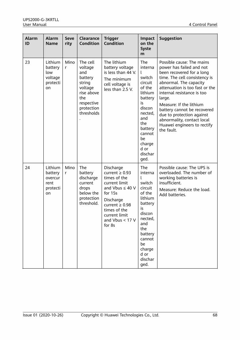
AlarmID
AlarmName
Severity
ClearanceCondition
TriggerCondition
Impacton theSystem
Suggestion
23 Lithiumbatterylowvoltageprotection
Minor
The cellvoltageandbatterystringvoltagerise abovetherespectiveprotectionthresholds.
The lithiumbattery voltageis less than 44 V.The minimumcell voltage isless than 2.5 V.
Theinternalswitchcircuitof thelithiumbatteryisdisconnected,andthebatterycannotbecharged ordischarged.
Possible cause: The mainspower has failed and notbeen recovered for a longtime. The cell consistency isabnormal. The capacityattenuation is too fast or theinternal resistance is toolarge.Measure: If the lithiumbattery cannot be recovereddue to protection againstabnormality, contact localHuawei engineers to rectifythe fault.
24 Lithiumbatteryovercurrentprotection
Minor
Thebatterydischargecurrentdropsbelow theprotectionthreshold.
Dischargecurrent ≥ 0.93times of thecurrent limitand Vbus ≤ 40 Vfor 15sDischargecurrent ≥ 0.98times of thecurrent limitand Vbus < 17 Vfor 8s
Theinternalswitchcircuitof thelithiumbatteryisdisconnected,andthebatterycannotbecharged ordischarged.
Possible cause: The UPS isoverloaded. The number ofworking batteries isinsufficient.Measure: Reduce the load.Add batteries.
UPS2000-G-3KRTLLUser Manual 4 Control Panel
Issue 01 (2020-10-26) Copyright © Huawei Technologies Co., Ltd. 68
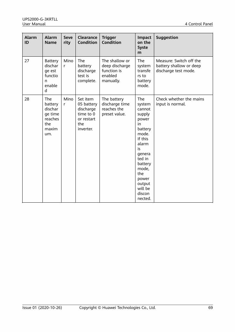
AlarmID
AlarmName
Severity
ClearanceCondition
TriggerCondition
Impacton theSystem
Suggestion
27 Batterydischarge estfunctionenabled
Minor
Thebatterydischargetest iscomplete.
The shallow ordeep dischargefunction isenabledmanually.
Thesystemtransfers tobatterymode.
Measure: Switch off thebattery shallow or deepdischarge test mode.
28 Thebatterydischarge timereachesthemaximum.
Minor
Set item05 batterydischargetime to 0or restarttheinverter.
The batterydischarge timereaches thepreset value.
Thesystemcannotsupplypowerinbatterymode.If thisalarmisgenerated inbatterymode,thepoweroutputwill bedisconnected.
Check whether the mainsinput is normal.
UPS2000-G-3KRTLLUser Manual 4 Control Panel
Issue 01 (2020-10-26) Copyright © Huawei Technologies Co., Ltd. 69
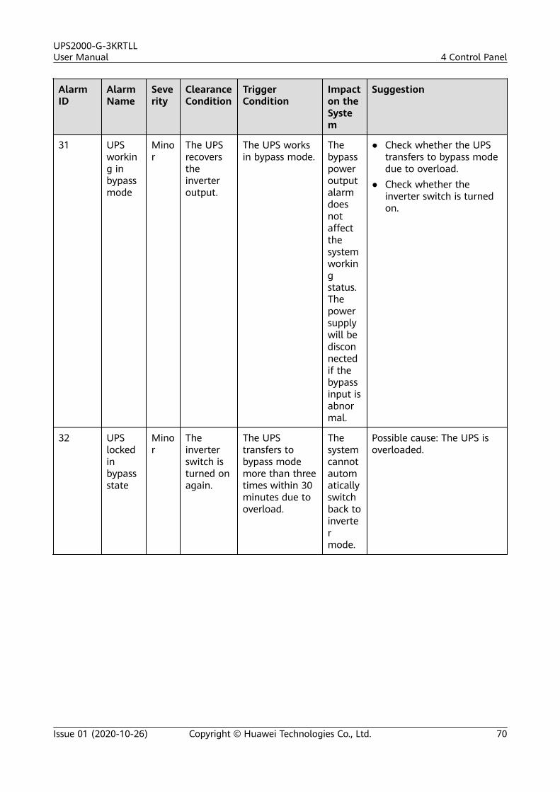
AlarmID
AlarmName
Severity
ClearanceCondition
TriggerCondition
Impacton theSystem
Suggestion
31 UPSworking inbypassmode
Minor
The UPSrecoverstheinverteroutput.
The UPS worksin bypass mode.
Thebypasspoweroutputalarmdoesnotaffectthesystemworkingstatus.Thepowersupplywill bedisconnectedif thebypassinput isabnormal.
● Check whether the UPStransfers to bypass modedue to overload.
● Check whether theinverter switch is turnedon.
32 UPSlockedinbypassstate
Minor
Theinverterswitch isturned onagain.
The UPStransfers tobypass modemore than threetimes within 30minutes due tooverload.
Thesystemcannotautomaticallyswitchback toinvertermode.
Possible cause: The UPS isoverloaded.
UPS2000-G-3KRTLLUser Manual 4 Control Panel
Issue 01 (2020-10-26) Copyright © Huawei Technologies Co., Ltd. 70
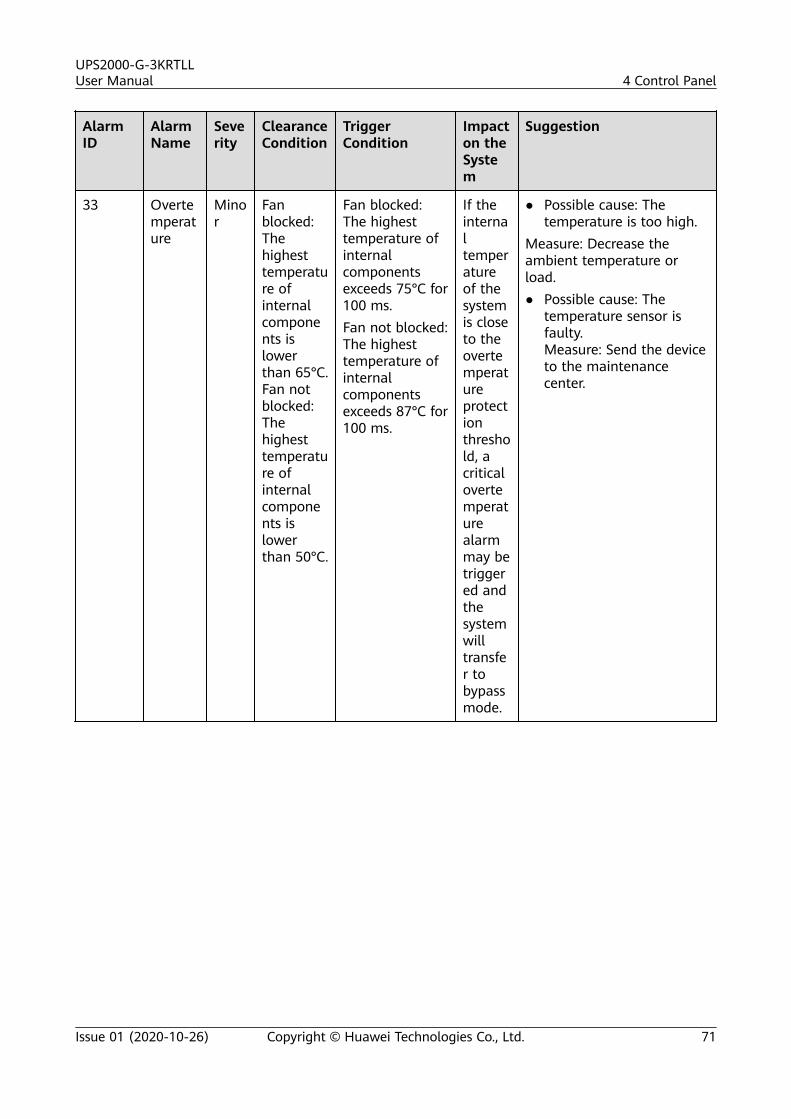
AlarmID
AlarmName
Severity
ClearanceCondition
TriggerCondition
Impacton theSystem
Suggestion
33 Overtemperature
Minor
Fanblocked:Thehighesttemperature ofinternalcomponents islowerthan 65°C.Fan notblocked:Thehighesttemperature ofinternalcomponents islowerthan 50°C.
Fan blocked:The highesttemperature ofinternalcomponentsexceeds 75°C for100 ms.Fan not blocked:The highesttemperature ofinternalcomponentsexceeds 87°C for100 ms.
If theinternaltemperatureof thesystemis closeto theovertemperatureprotectionthreshold, acriticalovertemperaturealarmmay betriggered andthesystemwilltransfer tobypassmode.
● Possible cause: Thetemperature is too high.
Measure: Decrease theambient temperature orload.● Possible cause: The
temperature sensor isfaulty.Measure: Send the deviceto the maintenancecenter.
UPS2000-G-3KRTLLUser Manual 4 Control Panel
Issue 01 (2020-10-26) Copyright © Huawei Technologies Co., Ltd. 71
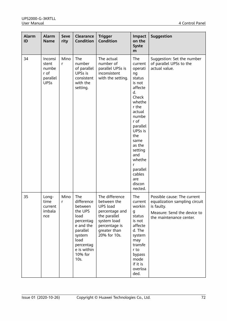
AlarmID
AlarmName
Severity
ClearanceCondition
TriggerCondition
Impacton theSystem
Suggestion
34 Inconsistentnumber ofparallelUPSs
Minor
Thenumberof parallelUPSs isconsistentwith thesetting.
The actualnumber ofparallel UPSs isinconsistentwith the setting.
Thecurrentoperatingstatusis notaffected.Checkwhether theactualnumber ofparallelUPSs isthesameas thesettingandwhetherparallelcablesaredisconnected.
Suggestion: Set the numberof parallel UPSs to theactual value.
35 Long-timecurrentimbalance
Minor
Thedifferencebetweenthe UPSloadpercentage and theparallelsystemloadpercentage is within10% for10s.
The differencebetween theUPS loadpercentage andthe parallelsystem loadpercentage isgreater than20% for 10s.
Thecurrentworkingstatusis notaffected. Thesystemmaytransfer tobypassmodeif it isoverloaded.
Possible cause: The currentequalization sampling circuitis faulty.Measure: Send the device tothe maintenance center.
UPS2000-G-3KRTLLUser Manual 4 Control Panel
Issue 01 (2020-10-26) Copyright © Huawei Technologies Co., Ltd. 72
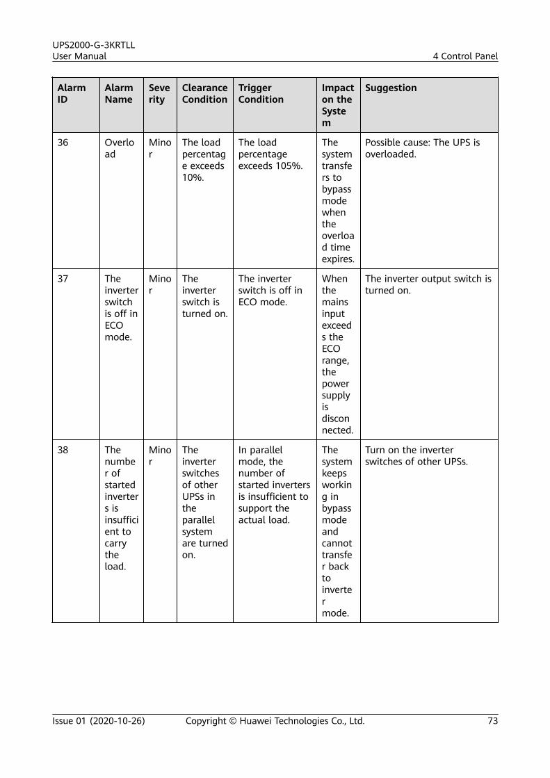
AlarmID
AlarmName
Severity
ClearanceCondition
TriggerCondition
Impacton theSystem
Suggestion
36 Overload
Minor
The loadpercentage exceeds10%.
The loadpercentageexceeds 105%.
Thesystemtransfers tobypassmodewhentheoverload timeexpires.
Possible cause: The UPS isoverloaded.
37 Theinverterswitchis off inECOmode.
Minor
Theinverterswitch isturned on.
The inverterswitch is off inECO mode.
Whenthemainsinputexceeds theECOrange,thepowersupplyisdisconnected.
The inverter output switch isturned on.
38 Thenumber ofstartedinverters isinsufficient tocarrytheload.
Minor
Theinverterswitchesof otherUPSs intheparallelsystemare turnedon.
In parallelmode, thenumber ofstarted invertersis insufficient tosupport theactual load.
Thesystemkeepsworking inbypassmodeandcannottransfer backtoinvertermode.
Turn on the inverterswitches of other UPSs.
UPS2000-G-3KRTLLUser Manual 4 Control Panel
Issue 01 (2020-10-26) Copyright © Huawei Technologies Co., Ltd. 73
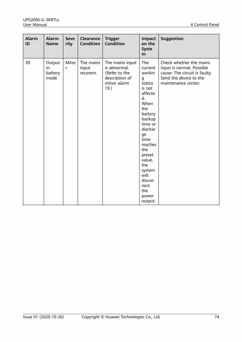
AlarmID
AlarmName
Severity
ClearanceCondition
TriggerCondition
Impacton theSystem
Suggestion
39 Outputinbatterymode
Minor
The mainsinputrecovers.
The mains inputis abnormal.(Refer to thedescription ofminor alarm19.)
Thecurrentworkingstatusis notaffected.Whenthebatterybackuptime ordischargetimereachesthepresetvalue,thesystemwilldisconnectthepoweroutput.
Check whether the mainsinput is normal. Possiblecause: The circuit is faulty.Send the device to themaintenance center.
UPS2000-G-3KRTLLUser Manual 4 Control Panel
Issue 01 (2020-10-26) Copyright © Huawei Technologies Co., Ltd. 74
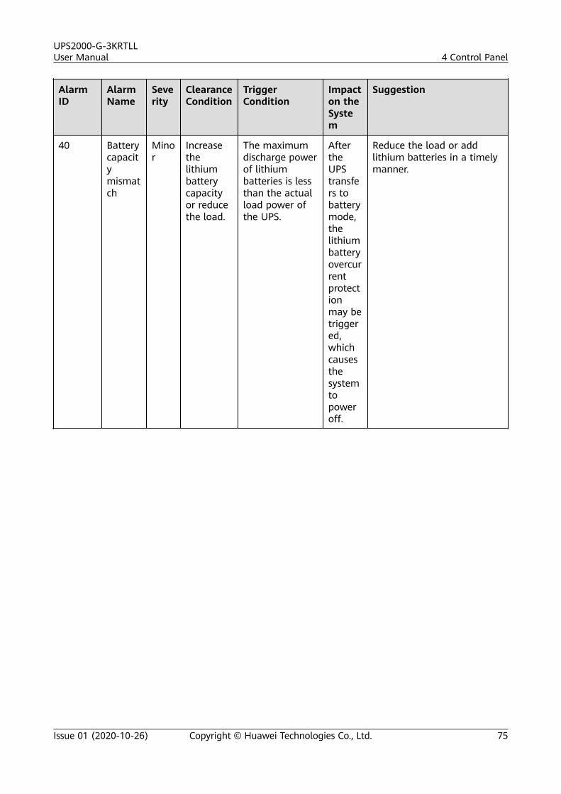
AlarmID
AlarmName
Severity
ClearanceCondition
TriggerCondition
Impacton theSystem
Suggestion
40 Batterycapacitymismatch
Minor
Increasethelithiumbatterycapacityor reducethe load.
The maximumdischarge powerof lithiumbatteries is lessthan the actualload power ofthe UPS.
AftertheUPStransfers tobatterymode,thelithiumbatteryovercurrentprotectionmay betriggered,whichcausesthesystemtopoweroff.
Reduce the load or addlithium batteries in a timelymanner.
UPS2000-G-3KRTLLUser Manual 4 Control Panel
Issue 01 (2020-10-26) Copyright © Huawei Technologies Co., Ltd. 75
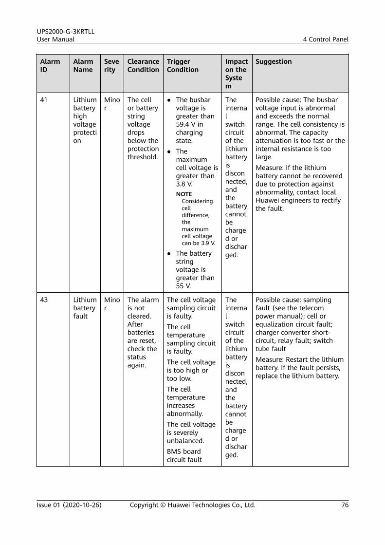
AlarmID
AlarmName
Severity
ClearanceCondition
TriggerCondition
Impacton theSystem
Suggestion
41 Lithiumbatteryhighvoltageprotection
Minor
The cellor batterystringvoltagedropsbelow theprotectionthreshold.
● The busbarvoltage isgreater than59.4 V inchargingstate.
● Themaximumcell voltage isgreater than3.8 V.NOTE
Consideringcelldifference,themaximumcell voltagecan be 3.9 V.
● The batterystringvoltage isgreater than55 V.
Theinternalswitchcircuitof thelithiumbatteryisdisconnected,andthebatterycannotbecharged ordischarged.
Possible cause: The busbarvoltage input is abnormaland exceeds the normalrange. The cell consistency isabnormal. The capacityattenuation is too fast or theinternal resistance is toolarge.Measure: If the lithiumbattery cannot be recovereddue to protection againstabnormality, contact localHuawei engineers to rectifythe fault.
43 Lithiumbatteryfault
Minor
The alarmis notcleared.Afterbatteriesare reset,check thestatusagain.
The cell voltagesampling circuitis faulty.The celltemperaturesampling circuitis faulty.The cell voltageis too high ortoo low.The celltemperatureincreasesabnormally.The cell voltageis severelyunbalanced.BMS boardcircuit fault
Theinternalswitchcircuitof thelithiumbatteryisdisconnected,andthebatterycannotbecharged ordischarged.
Possible cause: samplingfault (see the telecompower manual); cell orequalization circuit fault;charger converter short-circuit, relay fault; switchtube faultMeasure: Restart the lithiumbattery. If the fault persists,replace the lithium battery.
UPS2000-G-3KRTLLUser Manual 4 Control Panel
Issue 01 (2020-10-26) Copyright © Huawei Technologies Co., Ltd. 76
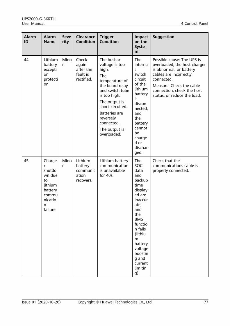
AlarmID
AlarmName
Severity
ClearanceCondition
TriggerCondition
Impacton theSystem
Suggestion
44 Lithiumbatteryexceptionprotection
Minor
Checkagainafter thefault isrectified.
The busbarvoltage is toohigh.Thetemperature ofthe board relayand switch tubeis too high.The output isshort-circuited.Batteries arereverselyconnected.The output isoverloaded.
Theinternalswitchcircuitof thelithiumbatteryisdisconnected,andthebatterycannotbecharged ordischarged.
Possible cause: The UPS isoverloaded, the host chargeris abnormal, or batterycables are incorrectlyconnected.Measure: Check the cableconnection, check the hoststatus, or reduce the load.
45 Chargershutdown duetolithiumbatterycommunicationfailure
Minor
Lithiumbatterycommunicationrecovers.
Lithium batterycommunicationis unavailablefor 40s.
TheSOCdataandbackuptimedisplayed areinaccurate,andtheBMSfunction fails(lithiumbatteryvoltageboosting andcurrentlimiting).
Check that thecommunications cable isproperly connected.
UPS2000-G-3KRTLLUser Manual 4 Control Panel
Issue 01 (2020-10-26) Copyright © Huawei Technologies Co., Ltd. 77
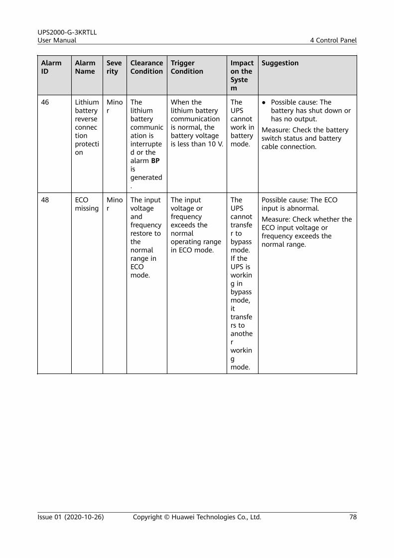
AlarmID
AlarmName
Severity
ClearanceCondition
TriggerCondition
Impacton theSystem
Suggestion
46 Lithiumbatteryreverseconnectionprotection
Minor
Thelithiumbatterycommunication isinterrupted or thealarm BPisgenerated.
When thelithium batterycommunicationis normal, thebattery voltageis less than 10 V.
TheUPScannotwork inbatterymode.
● Possible cause: Thebattery has shut down orhas no output.
Measure: Check the batteryswitch status and batterycable connection.
48 ECOmissing
Minor
The inputvoltageandfrequencyrestore tothenormalrange inECOmode.
The inputvoltage orfrequencyexceeds thenormaloperating rangein ECO mode.
TheUPScannottransfer tobypassmode.If theUPS isworking inbypassmode,ittransfers toanotherworkingmode.
Possible cause: The ECOinput is abnormal.Measure: Check whether theECO input voltage orfrequency exceeds thenormal range.
UPS2000-G-3KRTLLUser Manual 4 Control Panel
Issue 01 (2020-10-26) Copyright © Huawei Technologies Co., Ltd. 78
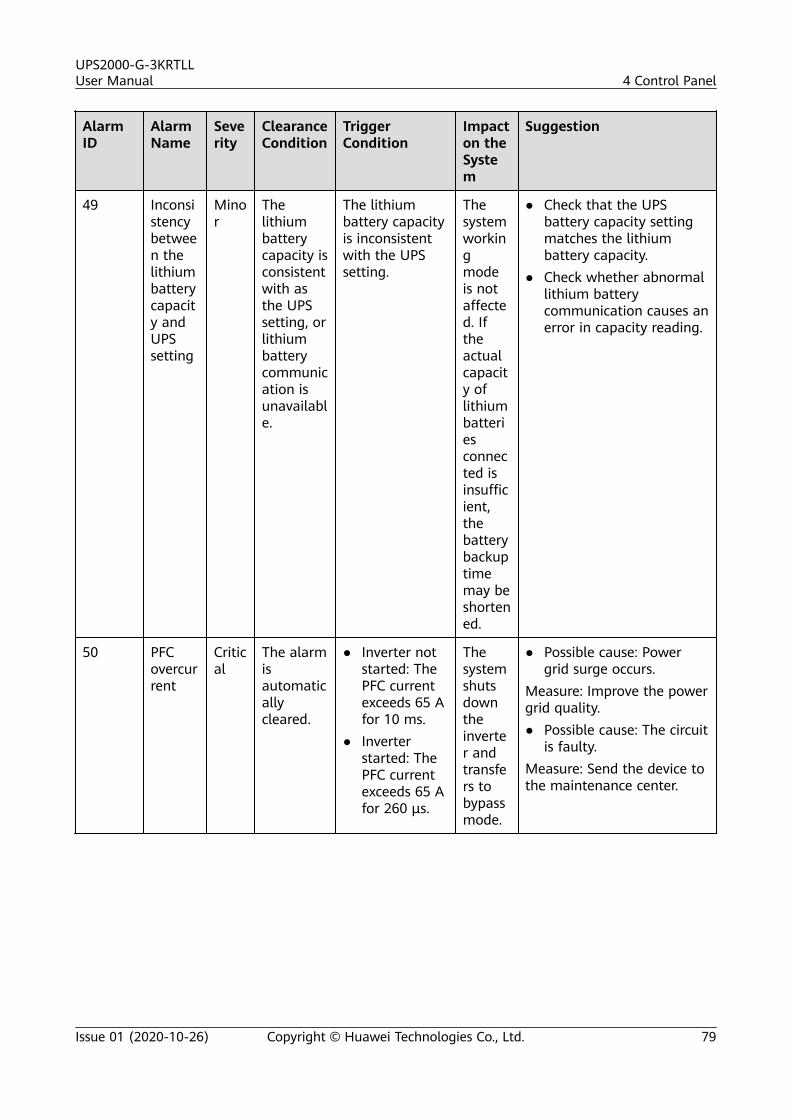
AlarmID
AlarmName
Severity
ClearanceCondition
TriggerCondition
Impacton theSystem
Suggestion
49 Inconsistencybetween thelithiumbatterycapacity andUPSsetting
Minor
Thelithiumbatterycapacity isconsistentwith asthe UPSsetting, orlithiumbatterycommunication isunavailable.
The lithiumbattery capacityis inconsistentwith the UPSsetting.
Thesystemworkingmodeis notaffected. Iftheactualcapacity oflithiumbatteriesconnected isinsufficient,thebatterybackuptimemay beshortened.
● Check that the UPSbattery capacity settingmatches the lithiumbattery capacity.
● Check whether abnormallithium batterycommunication causes anerror in capacity reading.
50 PFCovercurrent
Critical
The alarmisautomaticallycleared.
● Inverter notstarted: ThePFC currentexceeds 65 Afor 10 ms.
● Inverterstarted: ThePFC currentexceeds 65 Afor 260 μs.
Thesystemshutsdowntheinverter andtransfers tobypassmode.
● Possible cause: Powergrid surge occurs.
Measure: Improve the powergrid quality.● Possible cause: The circuit
is faulty.Measure: Send the device tothe maintenance center.
UPS2000-G-3KRTLLUser Manual 4 Control Panel
Issue 01 (2020-10-26) Copyright © Huawei Technologies Co., Ltd. 79
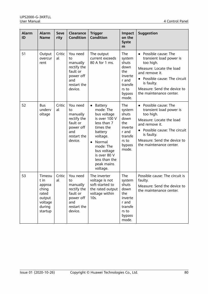
AlarmID
AlarmName
Severity
ClearanceCondition
TriggerCondition
Impacton theSystem
Suggestion
51 Outputovercurrent
Critical
You needtomanuallyrectify thefault orpower offandrestart thedevice.
The outputcurrent exceeds80 A for 1 ms.
Thesystemshutsdowntheinverter andtransfers tobypassmode.
● Possible cause: Thetransient load power istoo high.
Measure: Locate the loadand remove it.● Possible cause: The circuit
is faulty.Measure: Send the device tothe maintenance center.
52 Busundervoltage
Critical
You needtomanuallyrectify thefault orpower offandrestart thedevice.
● Batterymode: Thebus voltageis over 100 Vless than 7times thebatteryvoltage.
● Normalmode: Thebus voltageis over 80 Vless than thepeak mainsvoltage.
Thesystemshutsdowntheinverter andtransfers tobypassmode.
● Possible cause: Thetransient load power istoo high.
Measure: Locate the loadand remove it.● Possible cause: The circuit
is faulty.Measure: Send the device tothe maintenance center.
53 Timeout inapproachingratedoutputvoltageduringstartup
Critical
You needtomanuallyrectify thefault orpower offandrestart thedevice.
The invertervoltage is notsoft-started tothe rated outputvoltage within10s.
Thesystemshutsdowntheinverter andtransfers tobypassmode.
Possible cause: The circuit isfaulty.Measure: Send the device tothe maintenance center.
UPS2000-G-3KRTLLUser Manual 4 Control Panel
Issue 01 (2020-10-26) Copyright © Huawei Technologies Co., Ltd. 80
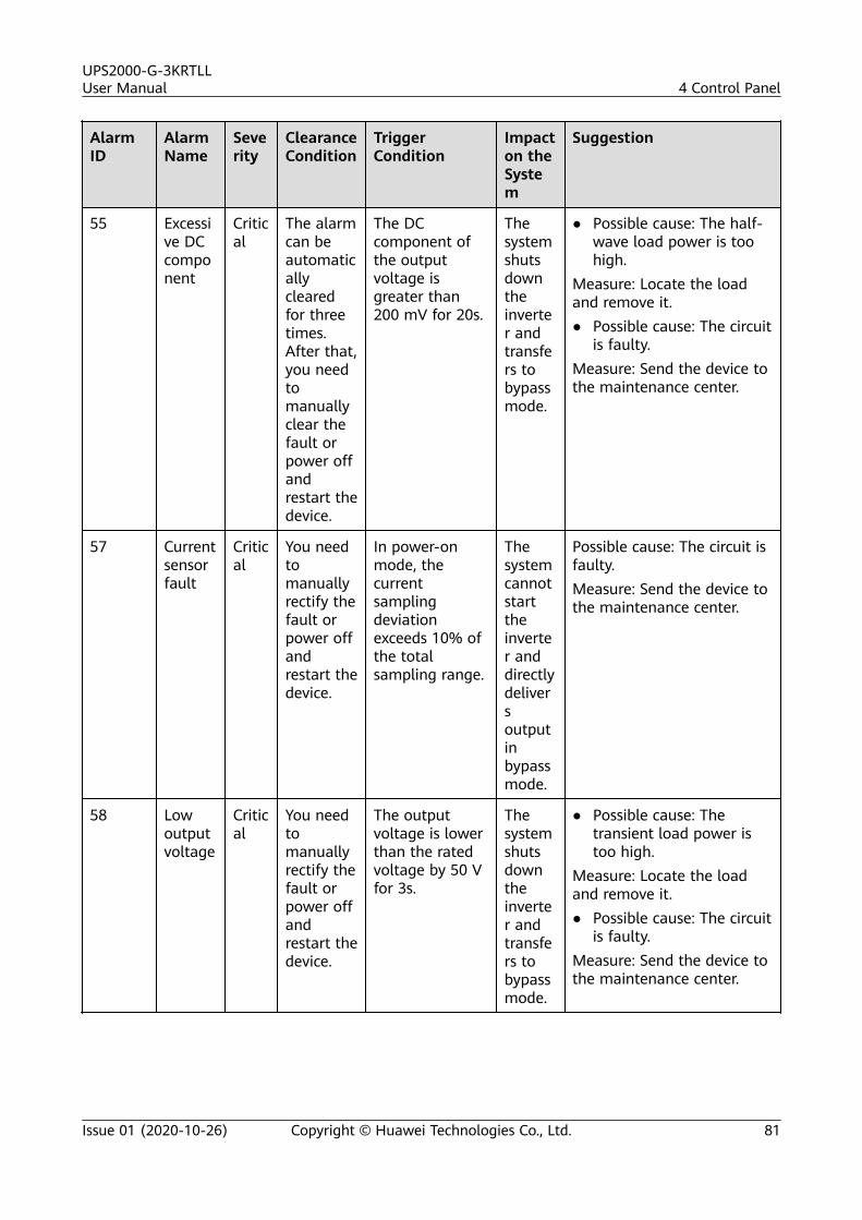
AlarmID
AlarmName
Severity
ClearanceCondition
TriggerCondition
Impacton theSystem
Suggestion
55 Excessive DCcomponent
Critical
The alarmcan beautomaticallyclearedfor threetimes.After that,you needtomanuallyclear thefault orpower offandrestart thedevice.
The DCcomponent ofthe outputvoltage isgreater than200 mV for 20s.
Thesystemshutsdowntheinverter andtransfers tobypassmode.
● Possible cause: The half-wave load power is toohigh.
Measure: Locate the loadand remove it.● Possible cause: The circuit
is faulty.Measure: Send the device tothe maintenance center.
57 Currentsensorfault
Critical
You needtomanuallyrectify thefault orpower offandrestart thedevice.
In power-onmode, thecurrentsamplingdeviationexceeds 10% ofthe totalsampling range.
Thesystemcannotstarttheinverter anddirectlydeliversoutputinbypassmode.
Possible cause: The circuit isfaulty.Measure: Send the device tothe maintenance center.
58 Lowoutputvoltage
Critical
You needtomanuallyrectify thefault orpower offandrestart thedevice.
The outputvoltage is lowerthan the ratedvoltage by 50 Vfor 3s.
Thesystemshutsdowntheinverter andtransfers tobypassmode.
● Possible cause: Thetransient load power istoo high.
Measure: Locate the loadand remove it.● Possible cause: The circuit
is faulty.Measure: Send the device tothe maintenance center.
UPS2000-G-3KRTLLUser Manual 4 Control Panel
Issue 01 (2020-10-26) Copyright © Huawei Technologies Co., Ltd. 81
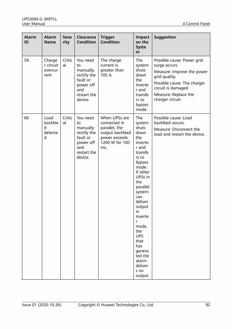
AlarmID
AlarmName
Severity
ClearanceCondition
TriggerCondition
Impacton theSystem
Suggestion
59 Charger circuitovercurrent
Critical
You needtomanuallyrectify thefault orpower offandrestart thedevice.
The chargecurrent isgreater than105 A.
Thesystemshutsdowntheinverter andtransfers tobypassmode.
Possible cause: Power gridsurge occurs.Measure: Improve the powergrid quality.Possible cause: The chargercircuit is damaged.Measure: Replace thecharger circuit.
60 Loadbackfeeddetected
Critical
You needtomanuallyrectify thefault orpower offandrestart thedevice.
When UPSs areconnected inparallel, theoutput backfeedpower exceeds1200 W for 100ms.
Thesystemshutsdowntheinverter andtransfers tobypassmode.If otherUPSs intheparallelsystemcandeliveroutputininvertermode,theUPSthathasgenerated thealarmdelivers nooutput.
Possible cause: Loadbackfeed occurs.Measure: Disconnect theload and restart the device.
UPS2000-G-3KRTLLUser Manual 4 Control Panel
Issue 01 (2020-10-26) Copyright © Huawei Technologies Co., Ltd. 82
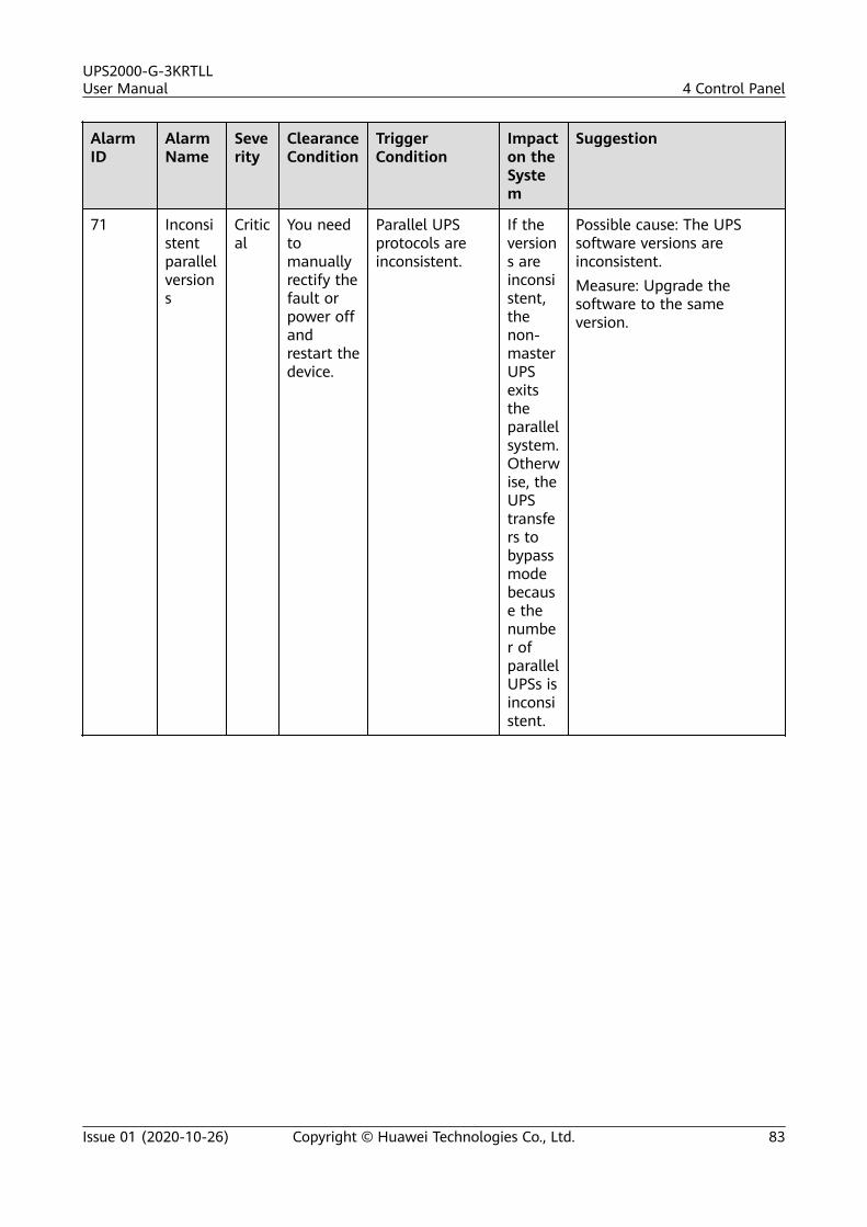
AlarmID
AlarmName
Severity
ClearanceCondition
TriggerCondition
Impacton theSystem
Suggestion
71 Inconsistentparallelversions
Critical
You needtomanuallyrectify thefault orpower offandrestart thedevice.
Parallel UPSprotocols areinconsistent.
If theversions areinconsistent,thenon-masterUPSexitstheparallelsystem.Otherwise, theUPStransfers tobypassmodebecause thenumber ofparallelUPSs isinconsistent.
Possible cause: The UPSsoftware versions areinconsistent.Measure: Upgrade thesoftware to the sameversion.
UPS2000-G-3KRTLLUser Manual 4 Control Panel
Issue 01 (2020-10-26) Copyright © Huawei Technologies Co., Ltd. 83
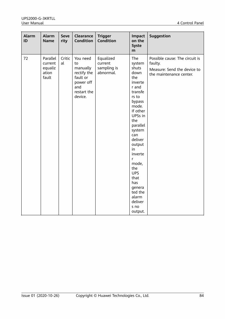
AlarmID
AlarmName
Severity
ClearanceCondition
TriggerCondition
Impacton theSystem
Suggestion
72 Parallelcurrentequalizationfault
Critical
You needtomanuallyrectify thefault orpower offandrestart thedevice.
Equalizedcurrentsampling isabnormal.
Thesystemshutsdowntheinverter andtransfers tobypassmode.If otherUPSs intheparallelsystemcandeliveroutputininvertermode,theUPSthathasgenerated thealarmdelivers nooutput.
Possible cause: The circuit isfaulty.Measure: Send the device tothe maintenance center.
UPS2000-G-3KRTLLUser Manual 4 Control Panel
Issue 01 (2020-10-26) Copyright © Huawei Technologies Co., Ltd. 84
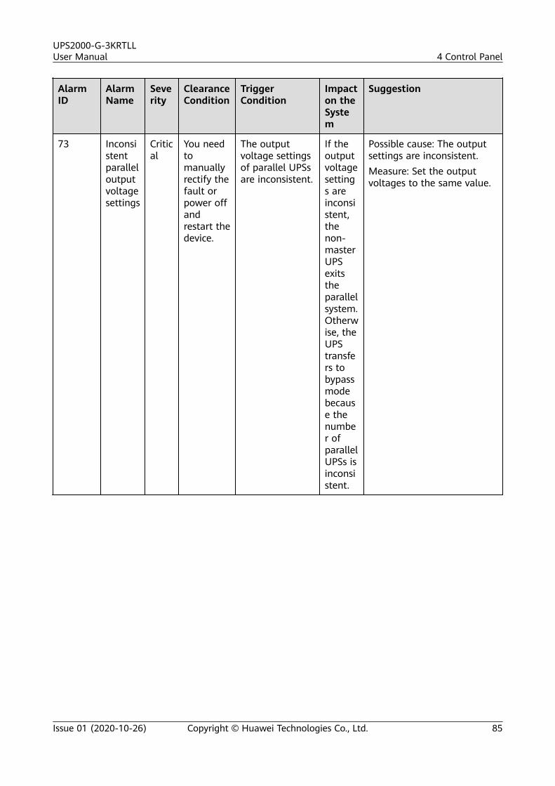
AlarmID
AlarmName
Severity
ClearanceCondition
TriggerCondition
Impacton theSystem
Suggestion
73 Inconsistentparalleloutputvoltagesettings
Critical
You needtomanuallyrectify thefault orpower offandrestart thedevice.
The outputvoltage settingsof parallel UPSsare inconsistent.
If theoutputvoltagesettings areinconsistent,thenon-masterUPSexitstheparallelsystem.Otherwise, theUPStransfers tobypassmodebecause thenumber ofparallelUPSs isinconsistent.
Possible cause: The outputsettings are inconsistent.Measure: Set the outputvoltages to the same value.
UPS2000-G-3KRTLLUser Manual 4 Control Panel
Issue 01 (2020-10-26) Copyright © Huawei Technologies Co., Ltd. 85
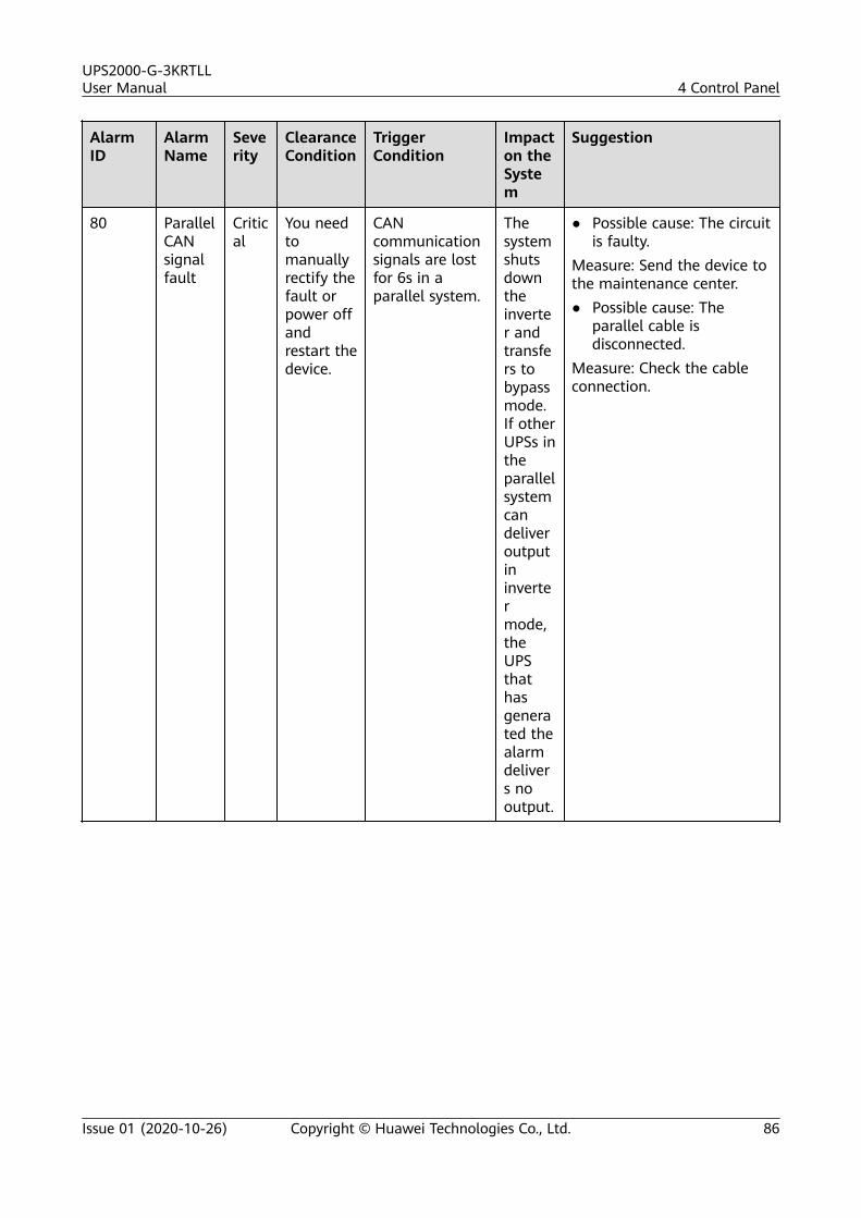
AlarmID
AlarmName
Severity
ClearanceCondition
TriggerCondition
Impacton theSystem
Suggestion
80 ParallelCANsignalfault
Critical
You needtomanuallyrectify thefault orpower offandrestart thedevice.
CANcommunicationsignals are lostfor 6s in aparallel system.
Thesystemshutsdowntheinverter andtransfers tobypassmode.If otherUPSs intheparallelsystemcandeliveroutputininvertermode,theUPSthathasgenerated thealarmdelivers nooutput.
● Possible cause: The circuitis faulty.
Measure: Send the device tothe maintenance center.● Possible cause: The
parallel cable isdisconnected.
Measure: Check the cableconnection.
UPS2000-G-3KRTLLUser Manual 4 Control Panel
Issue 01 (2020-10-26) Copyright © Huawei Technologies Co., Ltd. 86
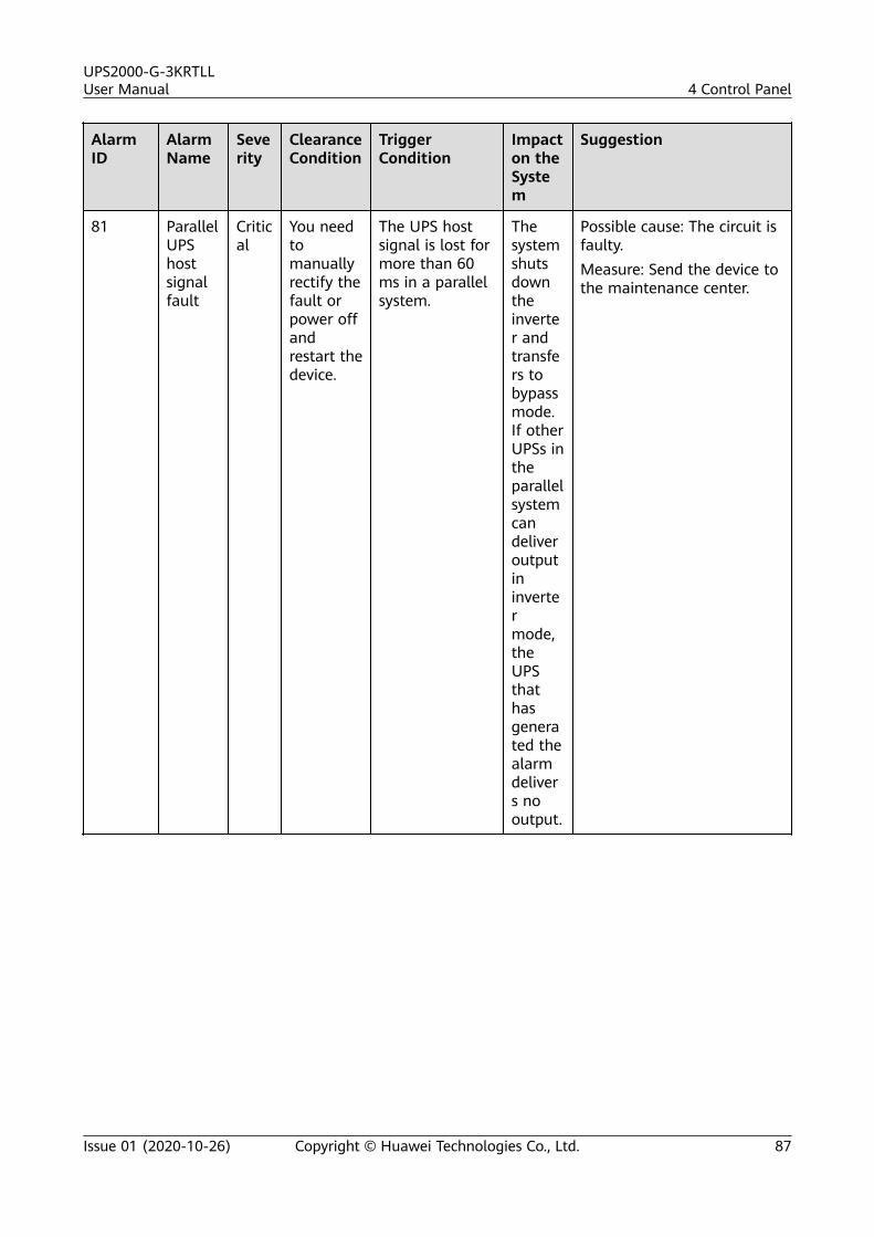
AlarmID
AlarmName
Severity
ClearanceCondition
TriggerCondition
Impacton theSystem
Suggestion
81 ParallelUPShostsignalfault
Critical
You needtomanuallyrectify thefault orpower offandrestart thedevice.
The UPS hostsignal is lost formore than 60ms in a parallelsystem.
Thesystemshutsdowntheinverter andtransfers tobypassmode.If otherUPSs intheparallelsystemcandeliveroutputininvertermode,theUPSthathasgenerated thealarmdelivers nooutput.
Possible cause: The circuit isfaulty.Measure: Send the device tothe maintenance center.
UPS2000-G-3KRTLLUser Manual 4 Control Panel
Issue 01 (2020-10-26) Copyright © Huawei Technologies Co., Ltd. 87
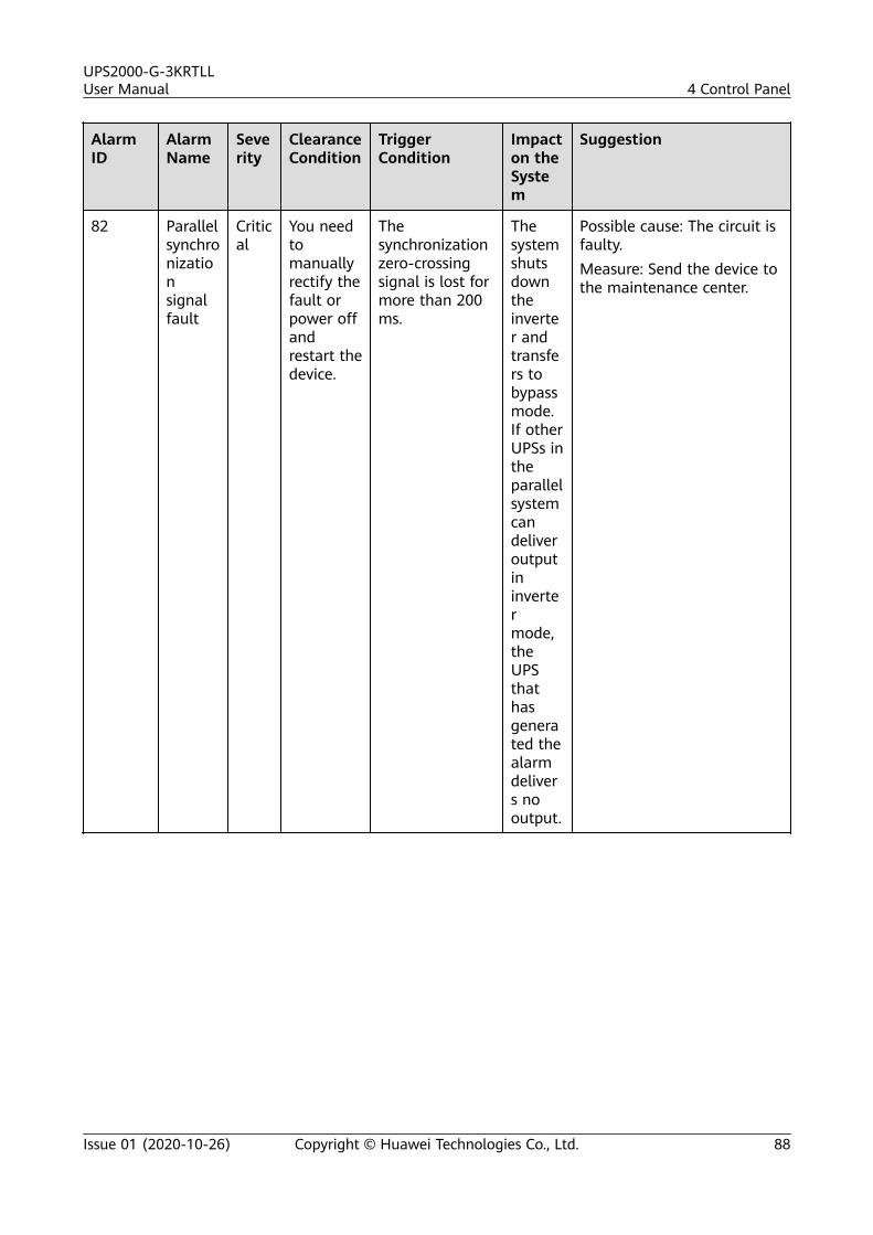
AlarmID
AlarmName
Severity
ClearanceCondition
TriggerCondition
Impacton theSystem
Suggestion
82 Parallelsynchronizationsignalfault
Critical
You needtomanuallyrectify thefault orpower offandrestart thedevice.
Thesynchronizationzero-crossingsignal is lost formore than 200ms.
Thesystemshutsdowntheinverter andtransfers tobypassmode.If otherUPSs intheparallelsystemcandeliveroutputininvertermode,theUPSthathasgenerated thealarmdelivers nooutput.
Possible cause: The circuit isfaulty.Measure: Send the device tothe maintenance center.
UPS2000-G-3KRTLLUser Manual 4 Control Panel
Issue 01 (2020-10-26) Copyright © Huawei Technologies Co., Ltd. 88
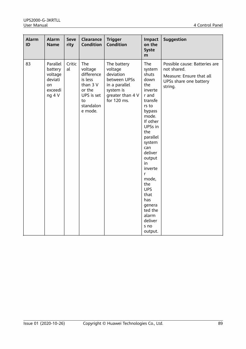
AlarmID
AlarmName
Severity
ClearanceCondition
TriggerCondition
Impacton theSystem
Suggestion
83 Parallelbatteryvoltagedeviationexceeding 4 V
Critical
Thevoltagedifferenceis lessthan 3 Vor theUPS is settostandalone mode.
The batteryvoltagedeviationbetween UPSsin a parallelsystem isgreater than 4 Vfor 120 ms.
Thesystemshutsdowntheinverter andtransfers tobypassmode.If otherUPSs intheparallelsystemcandeliveroutputininvertermode,theUPSthathasgenerated thealarmdelivers nooutput.
Possible cause: Batteries arenot shared.Measure: Ensure that allUPSs share one batterystring.
UPS2000-G-3KRTLLUser Manual 4 Control Panel
Issue 01 (2020-10-26) Copyright © Huawei Technologies Co., Ltd. 89
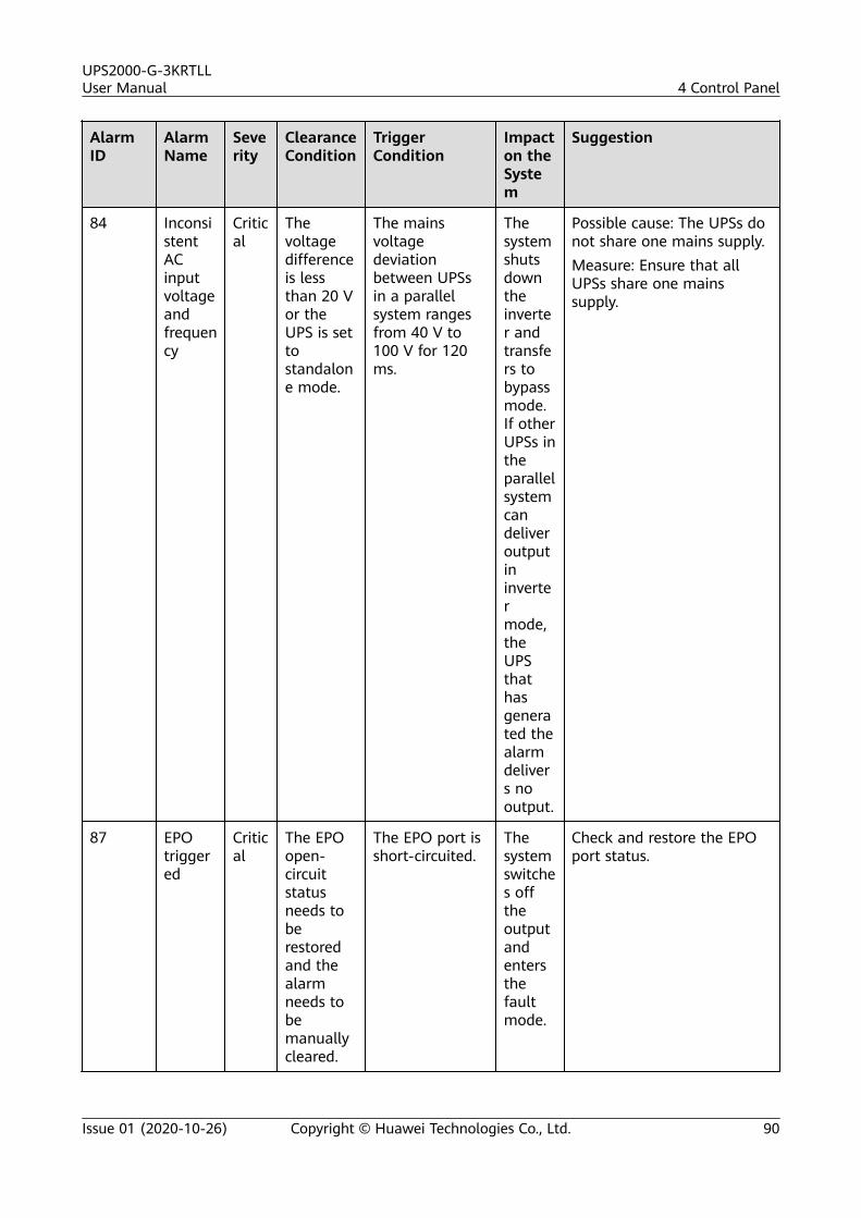
AlarmID
AlarmName
Severity
ClearanceCondition
TriggerCondition
Impacton theSystem
Suggestion
84 InconsistentACinputvoltageandfrequency
Critical
Thevoltagedifferenceis lessthan 20 Vor theUPS is settostandalone mode.
The mainsvoltagedeviationbetween UPSsin a parallelsystem rangesfrom 40 V to100 V for 120ms.
Thesystemshutsdowntheinverter andtransfers tobypassmode.If otherUPSs intheparallelsystemcandeliveroutputininvertermode,theUPSthathasgenerated thealarmdelivers nooutput.
Possible cause: The UPSs donot share one mains supply.Measure: Ensure that allUPSs share one mainssupply.
87 EPOtriggered
Critical
The EPOopen-circuitstatusneeds toberestoredand thealarmneeds tobemanuallycleared.
The EPO port isshort-circuited.
Thesystemswitches offtheoutputandentersthefaultmode.
Check and restore the EPOport status.
UPS2000-G-3KRTLLUser Manual 4 Control Panel
Issue 01 (2020-10-26) Copyright © Huawei Technologies Co., Ltd. 90
5 Operations
5.1 Checking Before Power-On
● AC power cable colors comply with local regulations.● The input and output are not short-circuited.● Cables and terminals are securely connected.● Battery cables and terminals are connected correctly, and voltages comply
with industry standards.● Power cables and signal cables are correctly identified.● Cables are neatly routed and securely bound.● Devices are installed and cables are routed in ways that facilitate
modification, capacity expansion, and maintenance.● The UPS is properly grounded.● The voltage between the neutral wire and the ground cable is less than 5 V
AC.
5.2 Single UPS Operations
5.2.1 Starting a UPS
NO TICE
● If no button is pressed within 20s in UPS setting mode, the LCD home screen isdisplayed.
● If no batteries are connected to the UPS of the long backup time model, thebuzzer keeps buzzing.
● To prevent triggering overload protection, start the loads with higher powerand then loads with lower power.
UPS2000-G-3KRTLLUser Manual 5 Operations
Issue 01 (2020-10-26) Copyright © Huawei Technologies Co., Ltd. 91
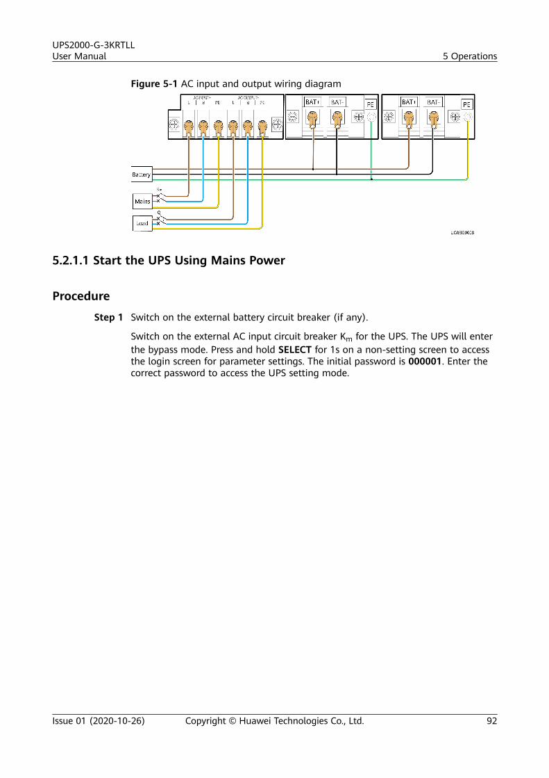
Figure 5-1 AC input and output wiring diagram
5.2.1.1 Start the UPS Using Mains Power
Procedure
Step 1 Switch on the external battery circuit breaker (if any).
Switch on the external AC input circuit breaker Km for the UPS. The UPS will enterthe bypass mode. Press and hold SELECT for 1s on a non-setting screen to accessthe login screen for parameter settings. The initial password is 000001. Enter thecorrect password to access the UPS setting mode.
UPS2000-G-3KRTLLUser Manual 5 Operations
Issue 01 (2020-10-26) Copyright © Huawei Technologies Co., Ltd. 92
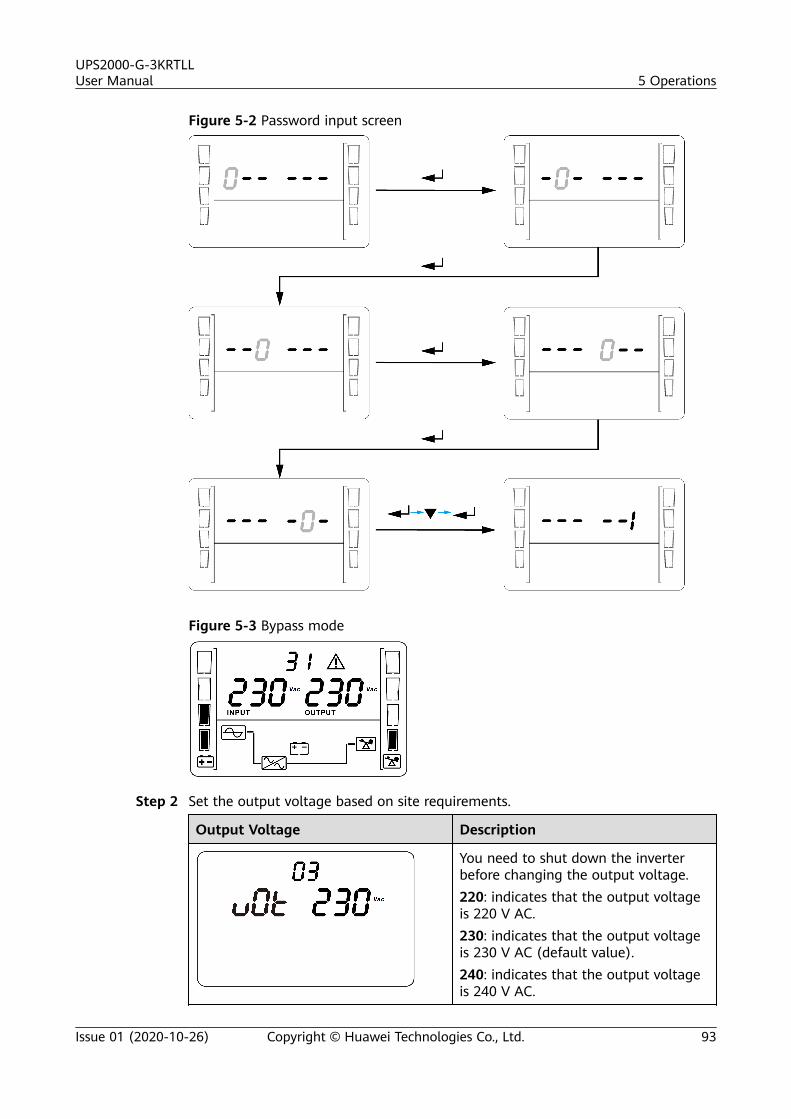
Figure 5-2 Password input screen
Figure 5-3 Bypass mode
Step 2 Set the output voltage based on site requirements.
Output Voltage Description
You need to shut down the inverterbefore changing the output voltage.220: indicates that the output voltageis 220 V AC.230: indicates that the output voltageis 230 V AC (default value).240: indicates that the output voltageis 240 V AC.
UPS2000-G-3KRTLLUser Manual 5 Operations
Issue 01 (2020-10-26) Copyright © Huawei Technologies Co., Ltd. 93
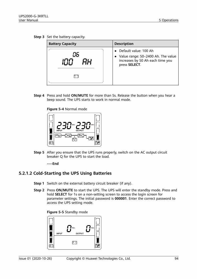
Step 3 Set the battery capacity.
Battery Capacity Description
● Default value: 100 Ah● Value range: 50–2400 Ah. The value
increases by 50 Ah each time youpress SELECT.
Step 4 Press and hold ON/MUTE for more than 5s. Release the button when you hear abeep sound. The UPS starts to work in normal mode.
Figure 5-4 Normal mode
Step 5 After you ensure that the UPS runs properly, switch on the AC output circuitbreaker Q for the UPS to start the load.
----End
5.2.1.2 Cold-Starting the UPS Using Batteries
Step 1 Switch on the external battery circuit breaker (if any).
Step 2 Press ON/MUTE to start the UPS. The UPS will enter the standby mode. Press andhold SELECT for 1s on a non-setting screen to access the login screen forparameter settings. The initial password is 000001. Enter the correct password toaccess the UPS setting mode.
Figure 5-5 Standby mode
UPS2000-G-3KRTLLUser Manual 5 Operations
Issue 01 (2020-10-26) Copyright © Huawei Technologies Co., Ltd. 94
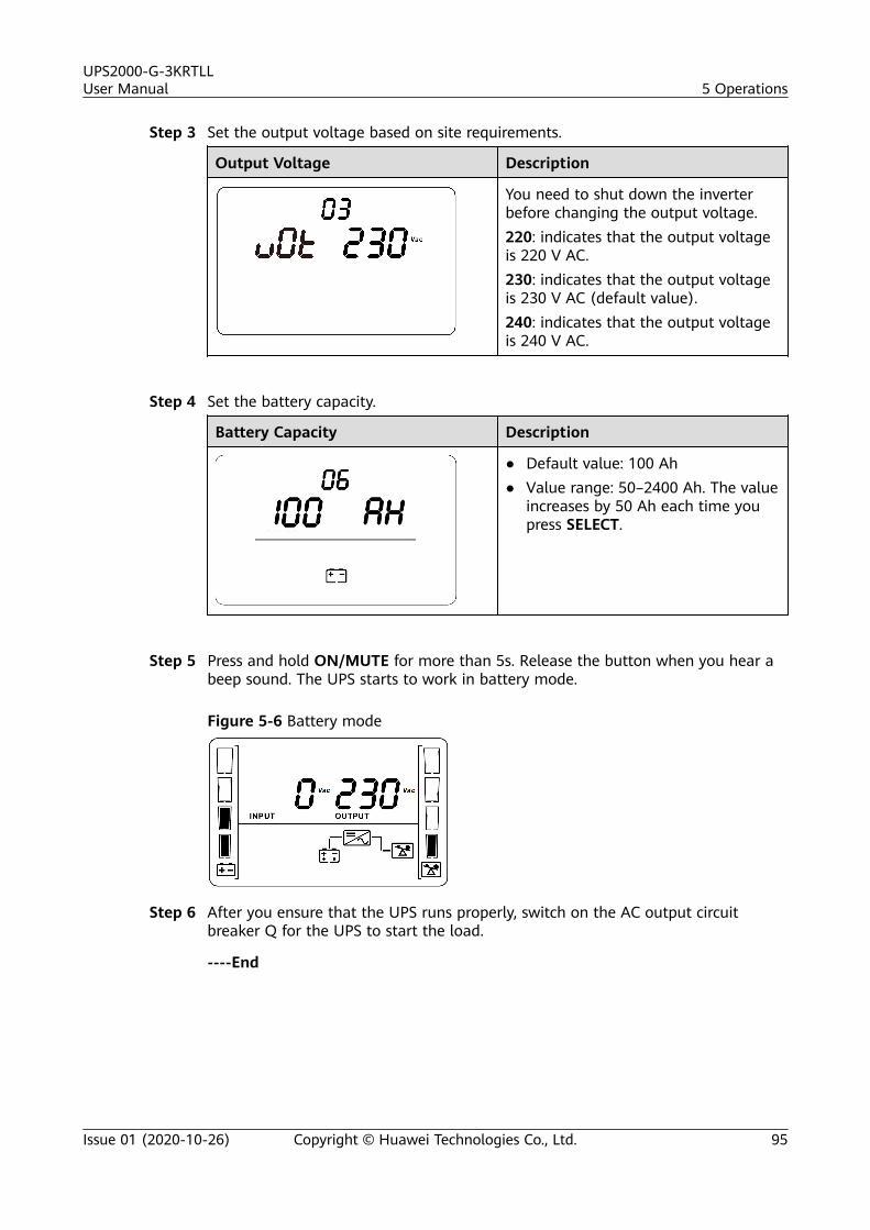
Step 3 Set the output voltage based on site requirements.
Output Voltage Description
You need to shut down the inverterbefore changing the output voltage.220: indicates that the output voltageis 220 V AC.230: indicates that the output voltageis 230 V AC (default value).240: indicates that the output voltageis 240 V AC.
Step 4 Set the battery capacity.
Battery Capacity Description
● Default value: 100 Ah● Value range: 50–2400 Ah. The value
increases by 50 Ah each time youpress SELECT.
Step 5 Press and hold ON/MUTE for more than 5s. Release the button when you hear abeep sound. The UPS starts to work in battery mode.
Figure 5-6 Battery mode
Step 6 After you ensure that the UPS runs properly, switch on the AC output circuitbreaker Q for the UPS to start the load.
----End
UPS2000-G-3KRTLLUser Manual 5 Operations
Issue 01 (2020-10-26) Copyright © Huawei Technologies Co., Ltd. 95
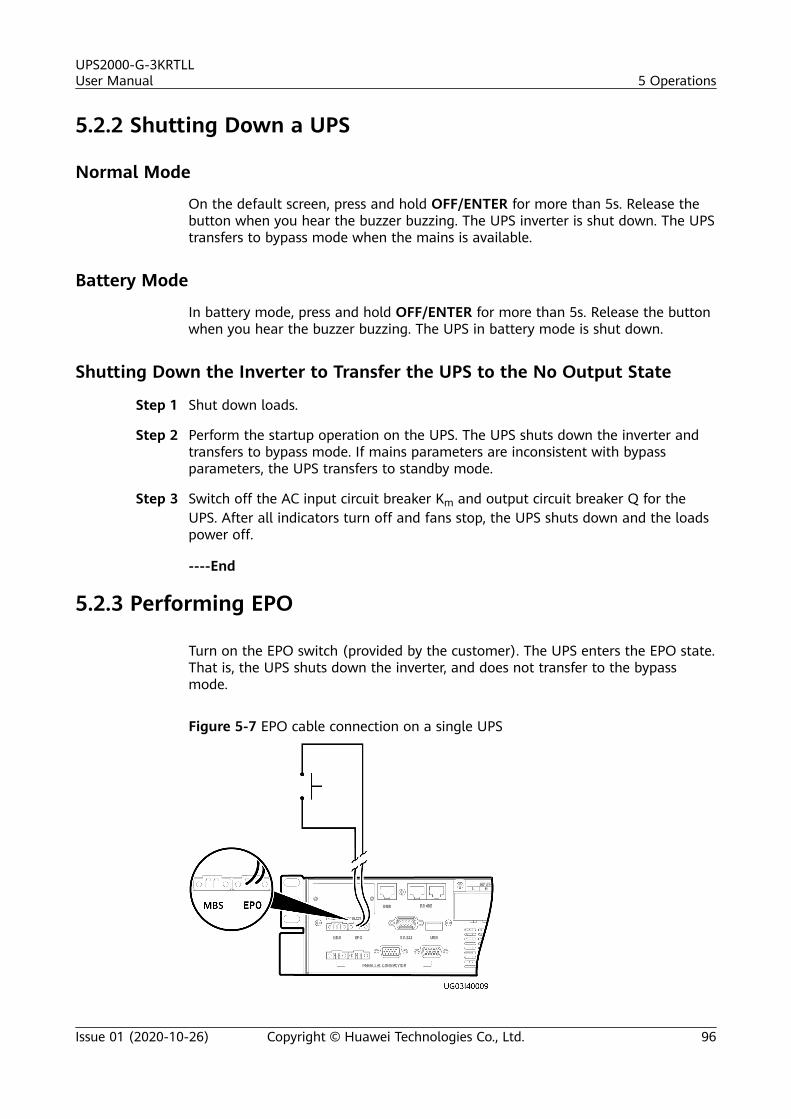
5.2.2 Shutting Down a UPS
Normal Mode
On the default screen, press and hold OFF/ENTER for more than 5s. Release thebutton when you hear the buzzer buzzing. The UPS inverter is shut down. The UPStransfers to bypass mode when the mains is available.
Battery Mode
In battery mode, press and hold OFF/ENTER for more than 5s. Release the buttonwhen you hear the buzzer buzzing. The UPS in battery mode is shut down.
Shutting Down the Inverter to Transfer the UPS to the No Output State
Step 1 Shut down loads.
Step 2 Perform the startup operation on the UPS. The UPS shuts down the inverter andtransfers to bypass mode. If mains parameters are inconsistent with bypassparameters, the UPS transfers to standby mode.
Step 3 Switch off the AC input circuit breaker Km and output circuit breaker Q for theUPS. After all indicators turn off and fans stop, the UPS shuts down and the loadspower off.
----End
5.2.3 Performing EPO
Turn on the EPO switch (provided by the customer). The UPS enters the EPO state.That is, the UPS shuts down the inverter, and does not transfer to the bypassmode.
Figure 5-7 EPO cable connection on a single UPS
UPS2000-G-3KRTLLUser Manual 5 Operations
Issue 01 (2020-10-26) Copyright © Huawei Technologies Co., Ltd. 96
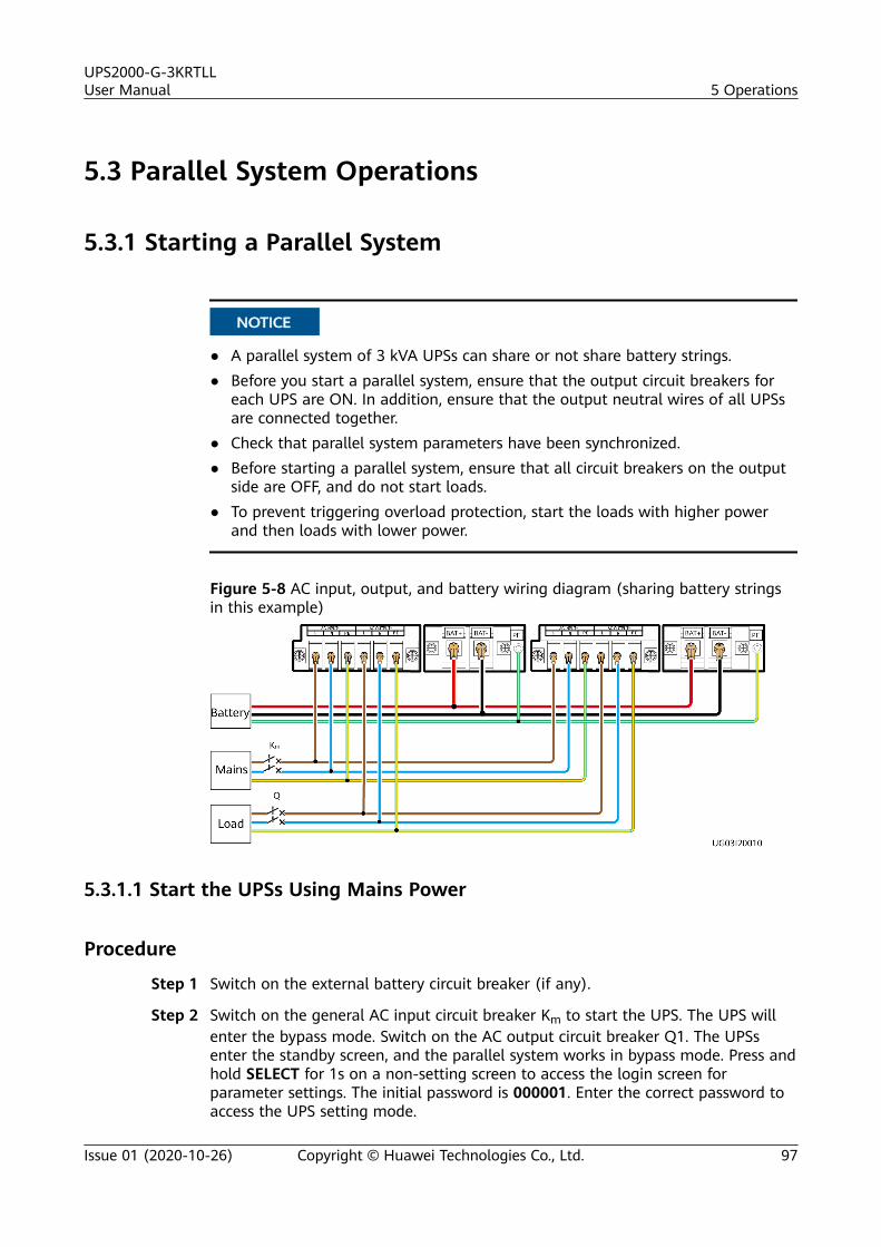
5.3 Parallel System Operations
5.3.1 Starting a Parallel System
NO TICE
● A parallel system of 3 kVA UPSs can share or not share battery strings.● Before you start a parallel system, ensure that the output circuit breakers for
each UPS are ON. In addition, ensure that the output neutral wires of all UPSsare connected together.
● Check that parallel system parameters have been synchronized.● Before starting a parallel system, ensure that all circuit breakers on the output
side are OFF, and do not start loads.● To prevent triggering overload protection, start the loads with higher power
and then loads with lower power.
Figure 5-8 AC input, output, and battery wiring diagram (sharing battery stringsin this example)
5.3.1.1 Start the UPSs Using Mains Power
Procedure
Step 1 Switch on the external battery circuit breaker (if any).
Step 2 Switch on the general AC input circuit breaker Km to start the UPS. The UPS willenter the bypass mode. Switch on the AC output circuit breaker Q1. The UPSsenter the standby screen, and the parallel system works in bypass mode. Press andhold SELECT for 1s on a non-setting screen to access the login screen forparameter settings. The initial password is 000001. Enter the correct password toaccess the UPS setting mode.
UPS2000-G-3KRTLLUser Manual 5 Operations
Issue 01 (2020-10-26) Copyright © Huawei Technologies Co., Ltd. 97
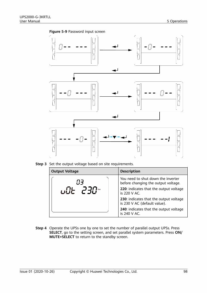
Figure 5-9 Password input screen
Step 3 Set the output voltage based on site requirements.
Output Voltage Description
You need to shut down the inverterbefore changing the output voltage.220: indicates that the output voltageis 220 V AC.230: indicates that the output voltageis 230 V AC (default value).240: indicates that the output voltageis 240 V AC.
Step 4 Operate the UPSs one by one to set the number of parallel output UPSs. PressSELECT, go to the setting screen, and set parallel system parameters. Press ON/MUTE+SELECT to return to the standby screen.
UPS2000-G-3KRTLLUser Manual 5 Operations
Issue 01 (2020-10-26) Copyright © Huawei Technologies Co., Ltd. 98
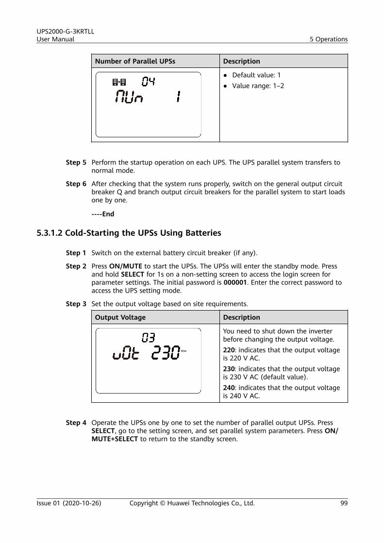
Number of Parallel UPSs Description
● Default value: 1● Value range: 1–2
Step 5 Perform the startup operation on each UPS. The UPS parallel system transfers tonormal mode.
Step 6 After checking that the system runs properly, switch on the general output circuitbreaker Q and branch output circuit breakers for the parallel system to start loadsone by one.
----End
5.3.1.2 Cold-Starting the UPSs Using Batteries
Step 1 Switch on the external battery circuit breaker (if any).
Step 2 Press ON/MUTE to start the UPSs. The UPSs will enter the standby mode. Pressand hold SELECT for 1s on a non-setting screen to access the login screen forparameter settings. The initial password is 000001. Enter the correct password toaccess the UPS setting mode.
Step 3 Set the output voltage based on site requirements.
Output Voltage Description
You need to shut down the inverterbefore changing the output voltage.220: indicates that the output voltageis 220 V AC.230: indicates that the output voltageis 230 V AC (default value).240: indicates that the output voltageis 240 V AC.
Step 4 Operate the UPSs one by one to set the number of parallel output UPSs. PressSELECT, go to the setting screen, and set parallel system parameters. Press ON/MUTE+SELECT to return to the standby screen.
UPS2000-G-3KRTLLUser Manual 5 Operations
Issue 01 (2020-10-26) Copyright © Huawei Technologies Co., Ltd. 99
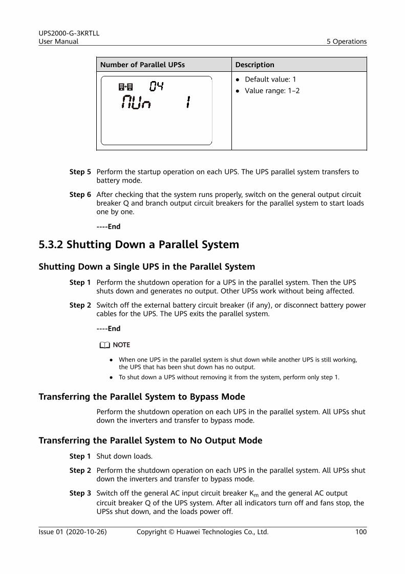
Number of Parallel UPSs Description
● Default value: 1● Value range: 1–2
Step 5 Perform the startup operation on each UPS. The UPS parallel system transfers tobattery mode.
Step 6 After checking that the system runs properly, switch on the general output circuitbreaker Q and branch output circuit breakers for the parallel system to start loadsone by one.
----End
5.3.2 Shutting Down a Parallel System
Shutting Down a Single UPS in the Parallel System
Step 1 Perform the shutdown operation for a UPS in the parallel system. Then the UPSshuts down and generates no output. Other UPSs work without being affected.
Step 2 Switch off the external battery circuit breaker (if any), or disconnect battery powercables for the UPS. The UPS exits the parallel system.
----End
NO TE
● When one UPS in the parallel system is shut down while another UPS is still working,the UPS that has been shut down has no output.
● To shut down a UPS without removing it from the system, perform only step 1.
Transferring the Parallel System to Bypass ModePerform the shutdown operation on each UPS in the parallel system. All UPSs shutdown the inverters and transfer to bypass mode.
Transferring the Parallel System to No Output Mode
Step 1 Shut down loads.
Step 2 Perform the shutdown operation on each UPS in the parallel system. All UPSs shutdown the inverters and transfer to bypass mode.
Step 3 Switch off the general AC input circuit breaker Km and the general AC outputcircuit breaker Q of the UPS system. After all indicators turn off and fans stop, theUPSs shut down, and the loads power off.
UPS2000-G-3KRTLLUser Manual 5 Operations
Issue 01 (2020-10-26) Copyright © Huawei Technologies Co., Ltd. 100
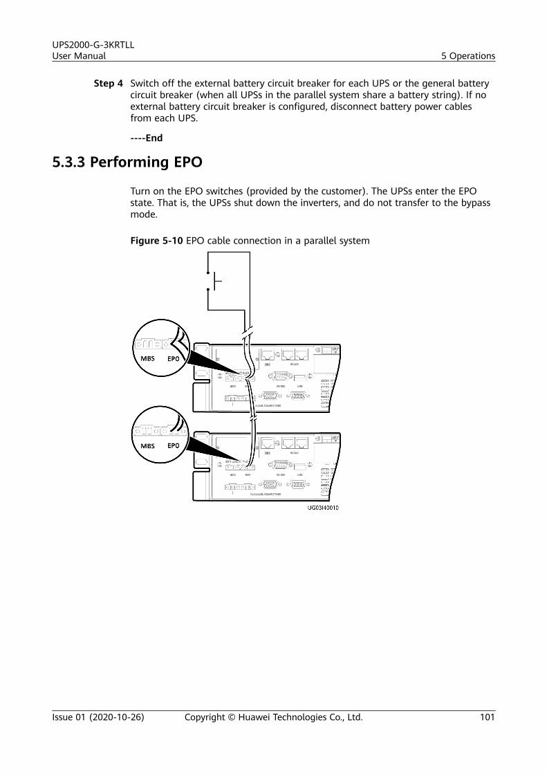
Step 4 Switch off the external battery circuit breaker for each UPS or the general batterycircuit breaker (when all UPSs in the parallel system share a battery string). If noexternal battery circuit breaker is configured, disconnect battery power cablesfrom each UPS.
----End
5.3.3 Performing EPO
Turn on the EPO switches (provided by the customer). The UPSs enter the EPOstate. That is, the UPSs shut down the inverters, and do not transfer to the bypassmode.
Figure 5-10 EPO cable connection in a parallel system
UPS2000-G-3KRTLLUser Manual 5 Operations
Issue 01 (2020-10-26) Copyright © Huawei Technologies Co., Ltd. 101
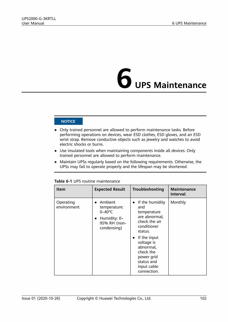
6 UPS Maintenance
NO TICE
● Only trained personnel are allowed to perform maintenance tasks. Beforeperforming operations on devices, wear ESD clothes, ESD gloves, and an ESDwrist strap. Remove conductive objects such as jewelry and watches to avoidelectric shocks or burns.
● Use insulated tools when maintaining components inside all devices. Onlytrained personnel are allowed to perform maintenance.
● Maintain UPSs regularly based on the following requirements. Otherwise, theUPSs may fail to operate properly and the lifespan may be shortened.
Table 6-1 UPS routine maintenance
Item Expected Result Troubleshooting MaintenanceInterval
Operatingenvironment
● Ambienttemperature:0–40°C
● Humidity: 0–95% RH (non-condensing)
● If the humidityandtemperatureare abnormal,check the airconditionerstatus.
● If the inputvoltage isabnormal,check thepower gridstatus andinput cableconnection.
Monthly
UPS2000-G-3KRTLLUser Manual 6 UPS Maintenance
Issue 01 (2020-10-26) Copyright © Huawei Technologies Co., Ltd. 102
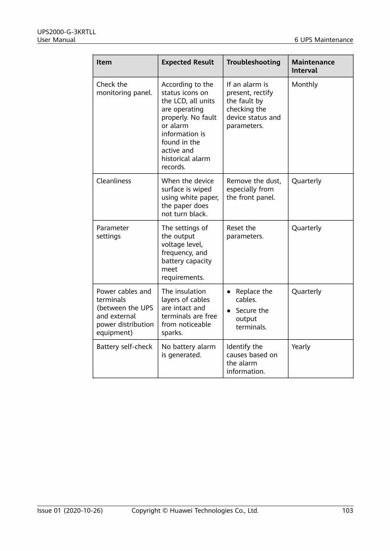
Item Expected Result Troubleshooting MaintenanceInterval
Check themonitoring panel.
According to thestatus icons onthe LCD, all unitsare operatingproperly. No faultor alarminformation isfound in theactive andhistorical alarmrecords.
If an alarm ispresent, rectifythe fault bychecking thedevice status andparameters.
Monthly
Cleanliness When the devicesurface is wipedusing white paper,the paper doesnot turn black.
Remove the dust,especially fromthe front panel.
Quarterly
Parametersettings
The settings ofthe outputvoltage level,frequency, andbattery capacitymeetrequirements.
Reset theparameters.
Quarterly
Power cables andterminals(between the UPSand externalpower distributionequipment)
The insulationlayers of cablesare intact andterminals are freefrom noticeablesparks.
● Replace thecables.
● Secure theoutputterminals.
Quarterly
Battery self-check No battery alarmis generated.
Identify thecauses based onthe alarminformation.
Yearly
UPS2000-G-3KRTLLUser Manual 6 UPS Maintenance
Issue 01 (2020-10-26) Copyright © Huawei Technologies Co., Ltd. 103
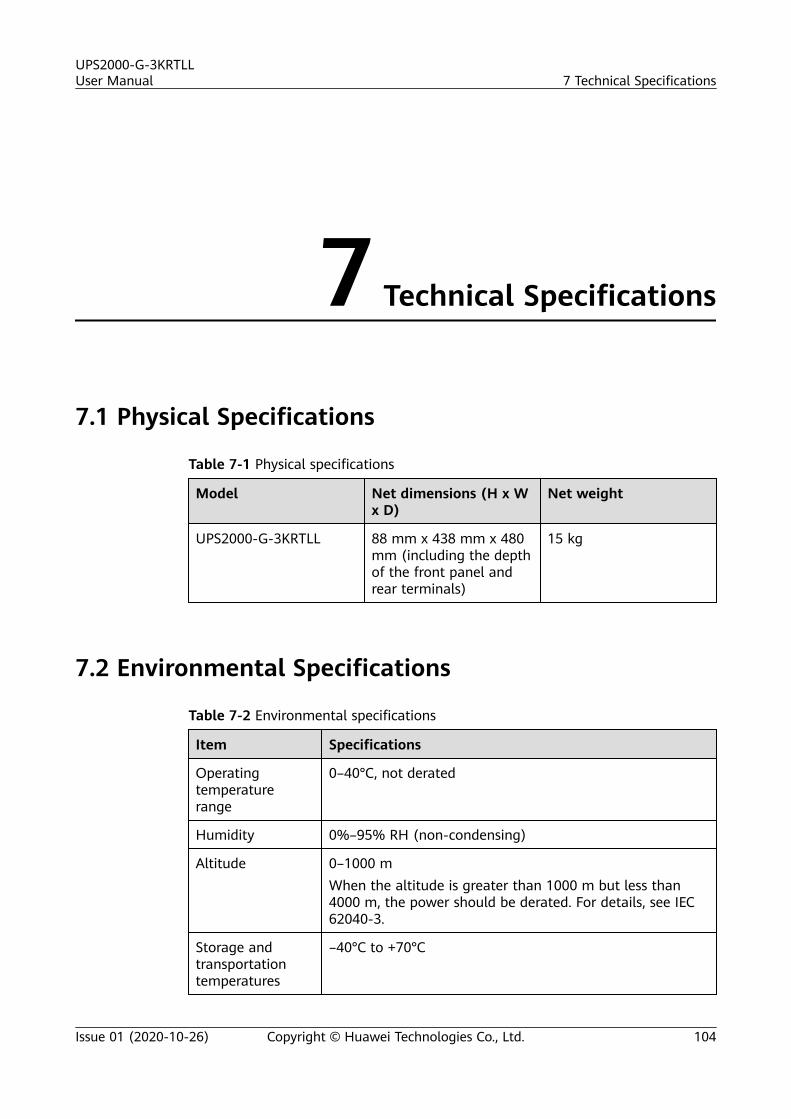
7 Technical Specifications
7.1 Physical Specifications
Table 7-1 Physical specifications
Model Net dimensions (H x Wx D)
Net weight
UPS2000-G-3KRTLL 88 mm x 438 mm x 480mm (including the depthof the front panel andrear terminals)
15 kg
7.2 Environmental Specifications
Table 7-2 Environmental specifications
Item Specifications
Operatingtemperaturerange
0–40°C, not derated
Humidity 0%–95% RH (non-condensing)
Altitude 0–1000 mWhen the altitude is greater than 1000 m but less than4000 m, the power should be derated. For details, see IEC62040-3.
Storage andtransportationtemperatures
–40°C to +70°C
UPS2000-G-3KRTLLUser Manual 7 Technical Specifications
Issue 01 (2020-10-26) Copyright © Huawei Technologies Co., Ltd. 104
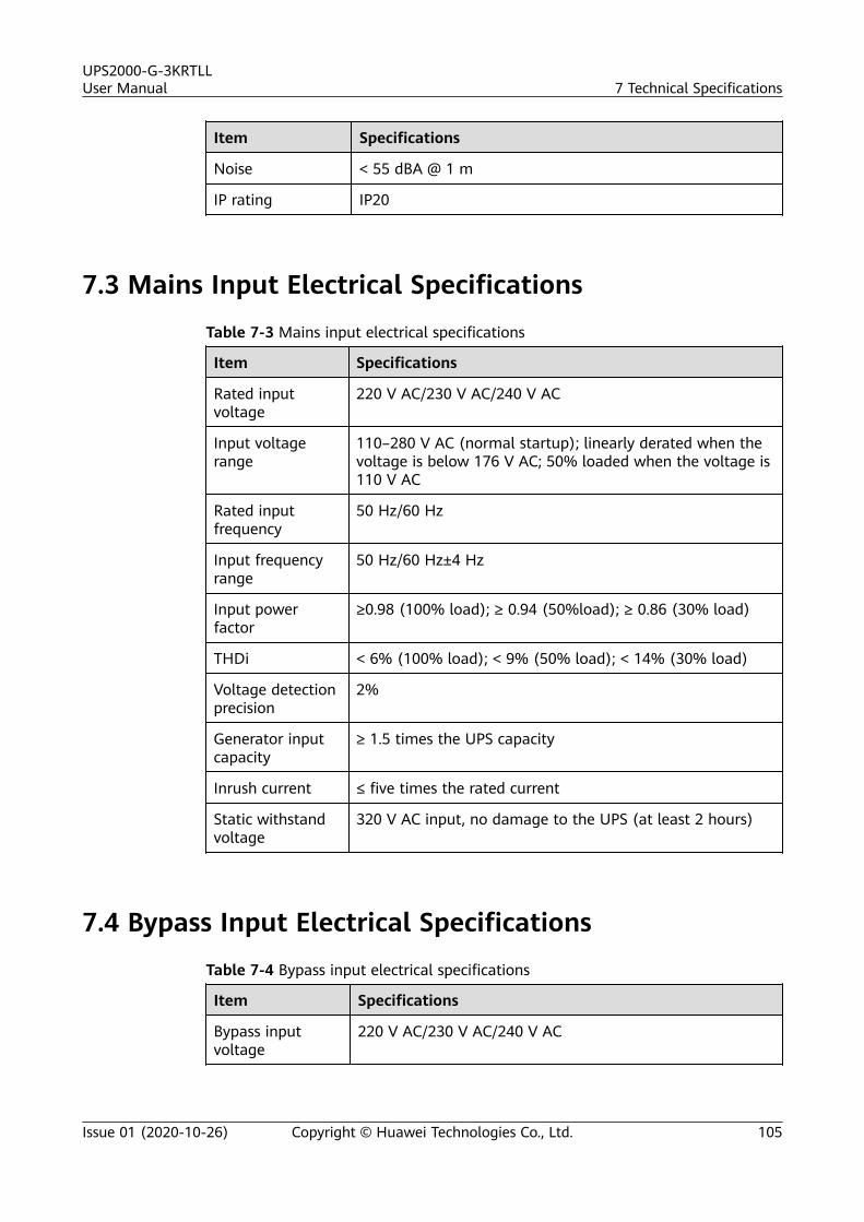
Item Specifications
Noise < 55 dBA @ 1 m
IP rating IP20
7.3 Mains Input Electrical Specifications
Table 7-3 Mains input electrical specifications
Item Specifications
Rated inputvoltage
220 V AC/230 V AC/240 V AC
Input voltagerange
110–280 V AC (normal startup); linearly derated when thevoltage is below 176 V AC; 50% loaded when the voltage is110 V AC
Rated inputfrequency
50 Hz/60 Hz
Input frequencyrange
50 Hz/60 Hz±4 Hz
Input powerfactor
≥0.98 (100% load); ≥ 0.94 (50%load); ≥ 0.86 (30% load)
THDi < 6% (100% load); < 9% (50% load); < 14% (30% load)
Voltage detectionprecision
2%
Generator inputcapacity
≥ 1.5 times the UPS capacity
Inrush current ≤ five times the rated current
Static withstandvoltage
320 V AC input, no damage to the UPS (at least 2 hours)
7.4 Bypass Input Electrical Specifications
Table 7-4 Bypass input electrical specifications
Item Specifications
Bypass inputvoltage
220 V AC/230 V AC/240 V AC
UPS2000-G-3KRTLLUser Manual 7 Technical Specifications
Issue 01 (2020-10-26) Copyright © Huawei Technologies Co., Ltd. 105
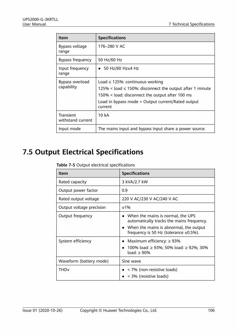
Item Specifications
Bypass voltagerange
176–280 V AC
Bypass frequency 50 Hz/60 Hz
Input frequencyrange
● 50 Hz/60 Hz±4 Hz
Bypass overloadcapability
Load ≤ 125%: continuous working125% < load ≤ 150%: disconnect the output after 1 minute150% < load: disconnect the output after 100 msLoad in bypass mode = Output current/Rated outputcurrent
Transientwithstand current
10 kA
Input mode The mains input and bypass input share a power source.
7.5 Output Electrical Specifications
Table 7-5 Output electrical specifications
Item Specifications
Rated capacity 3 kVA/2.7 kW
Output power factor 0.9
Rated output voltage 220 V AC/230 V AC/240 V AC
Output voltage precision ±1%
Output frequency ● When the mains is normal, the UPSautomatically tracks the mains frequency.
● When the mains is abnormal, the outputfrequency is 50 Hz (tolerance ±0.5%).
System efficiency ● Maximum efficiency: ≥ 93%● 100% load: ≥ 93%; 50% load: ≥ 92%; 30%
load: ≥ 90%
Waveform (battery mode) Sine wave
THDv ● < 7% (non-resistive loads)● < 3% (resistive loads)
UPS2000-G-3KRTLLUser Manual 7 Technical Specifications
Issue 01 (2020-10-26) Copyright © Huawei Technologies Co., Ltd. 106
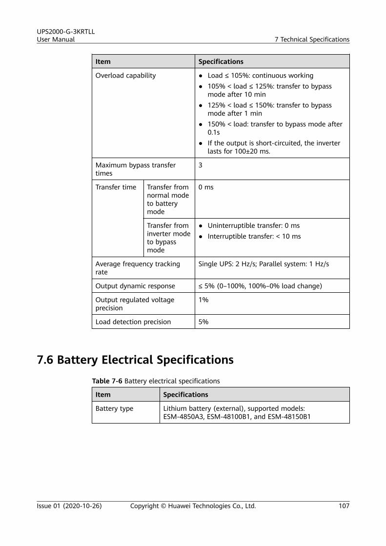
Item Specifications
Overload capability ● Load ≤ 105%: continuous working● 105% < load ≤ 125%: transfer to bypass
mode after 10 min● 125% < load ≤ 150%: transfer to bypass
mode after 1 min● 150% < load: transfer to bypass mode after
0.1s● If the output is short-circuited, the inverter
lasts for 100±20 ms.
Maximum bypass transfertimes
3
Transfer time Transfer fromnormal modeto batterymode
0 ms
Transfer frominverter modeto bypassmode
● Uninterruptible transfer: 0 ms● Interruptible transfer: < 10 ms
Average frequency trackingrate
Single UPS: 2 Hz/s; Parallel system: 1 Hz/s
Output dynamic response ≤ 5% (0–100%, 100%–0% load change)
Output regulated voltageprecision
1%
Load detection precision 5%
7.6 Battery Electrical Specifications
Table 7-6 Battery electrical specifications
Item Specifications
Battery type Lithium battery (external), supported models:ESM-4850A3, ESM-48100B1, and ESM-48150B1
UPS2000-G-3KRTLLUser Manual 7 Technical Specifications
Issue 01 (2020-10-26) Copyright © Huawei Technologies Co., Ltd. 107
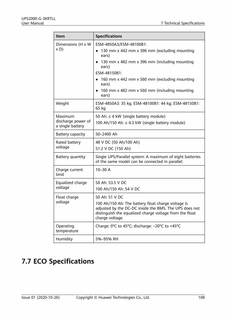
Item Specifications
Dimensions (H x Wx D)
ESM-4850A3/ESM-48100B1:● 130 mm x 442 mm x 396 mm (excluding mounting
ears)● 130 mm x 482 mm x 396 mm (including mounting
ears)ESM-48150B1:● 160 mm x 442 mm x 560 mm (excluding mounting
ears)● 160 mm x 482 mm x 560 mm (including mounting
ears)
Weight ESM-4850A3: 35 kg; ESM-48100B1: 44 kg; ESM-48150B1:65 kg
Maximumdischarge power ofa single battery
50 Ah: ≤ 4 kW (single battery module)100 Ah/150 Ah: ≤ 4.3 kW (single battery module)
Battery capacity 50–2400 Ah
Rated batteryvoltage
48 V DC (50 Ah/100 Ah)51.2 V DC (150 Ah)
Battery quantity Single UPS/Parallel system: A maximum of eight batteriesof the same model can be connected in parallel.
Charge currentlimit
10–30 A
Equalized chargevoltage
50 Ah: 53.5 V DC100 Ah/150 Ah: 54 V DC
Float chargevoltage
50 Ah: 51 V DC100 Ah/150 Ah: The battery float charge voltage isadjusted by the DC-DC inside the BMS. The UPS does notdistinguish the equalized charge voltage from the floatcharge voltage.
Operatingtemperature
Charge: 0°C to 45°C; discharge: –20°C to +45°C
Humidity 5%–95% RH
7.7 ECO Specifications
UPS2000-G-3KRTLLUser Manual 7 Technical Specifications
Issue 01 (2020-10-26) Copyright © Huawei Technologies Co., Ltd. 108
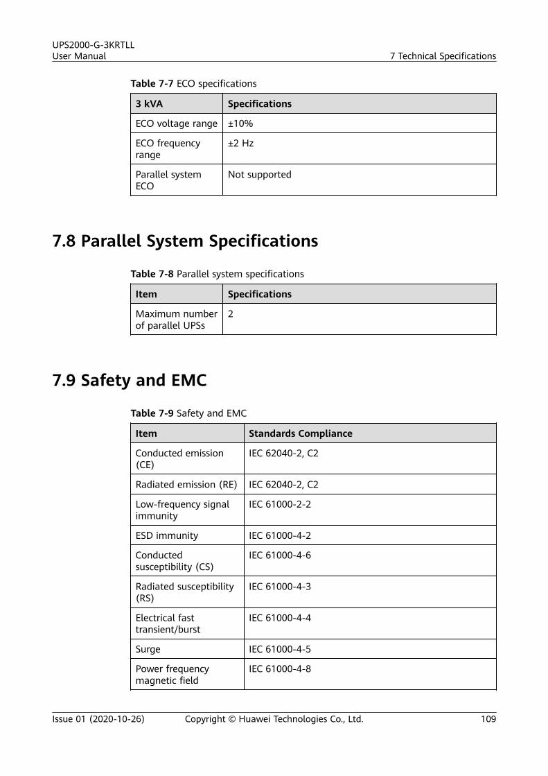
Table 7-7 ECO specifications
3 kVA Specifications
ECO voltage range ±10%
ECO frequencyrange
±2 Hz
Parallel systemECO
Not supported
7.8 Parallel System Specifications
Table 7-8 Parallel system specifications
Item Specifications
Maximum numberof parallel UPSs
2
7.9 Safety and EMC
Table 7-9 Safety and EMC
Item Standards Compliance
Conducted emission(CE)
IEC 62040-2, C2
Radiated emission (RE) IEC 62040-2, C2
Low-frequency signalimmunity
IEC 61000-2-2
ESD immunity IEC 61000-4-2
Conductedsusceptibility (CS)
IEC 61000-4-6
Radiated susceptibility(RS)
IEC 61000-4-3
Electrical fasttransient/burst
IEC 61000-4-4
Surge IEC 61000-4-5
Power frequencymagnetic field
IEC 61000-4-8
UPS2000-G-3KRTLLUser Manual 7 Technical Specifications
Issue 01 (2020-10-26) Copyright © Huawei Technologies Co., Ltd. 109
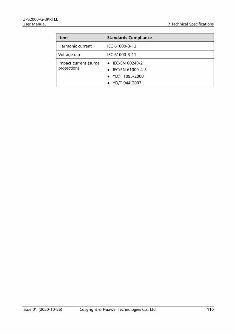
Item Standards Compliance
Harmonic current IEC 61000-3-12
Voltage dip IEC 61000-3-11
Impact current (surgeprotection)
● IEC/EN 60240-2● IEC/EN 61000-4-5● YD/T 1095-2000● YD/T 944-2007
UPS2000-G-3KRTLLUser Manual 7 Technical Specifications
Issue 01 (2020-10-26) Copyright © Huawei Technologies Co., Ltd. 110
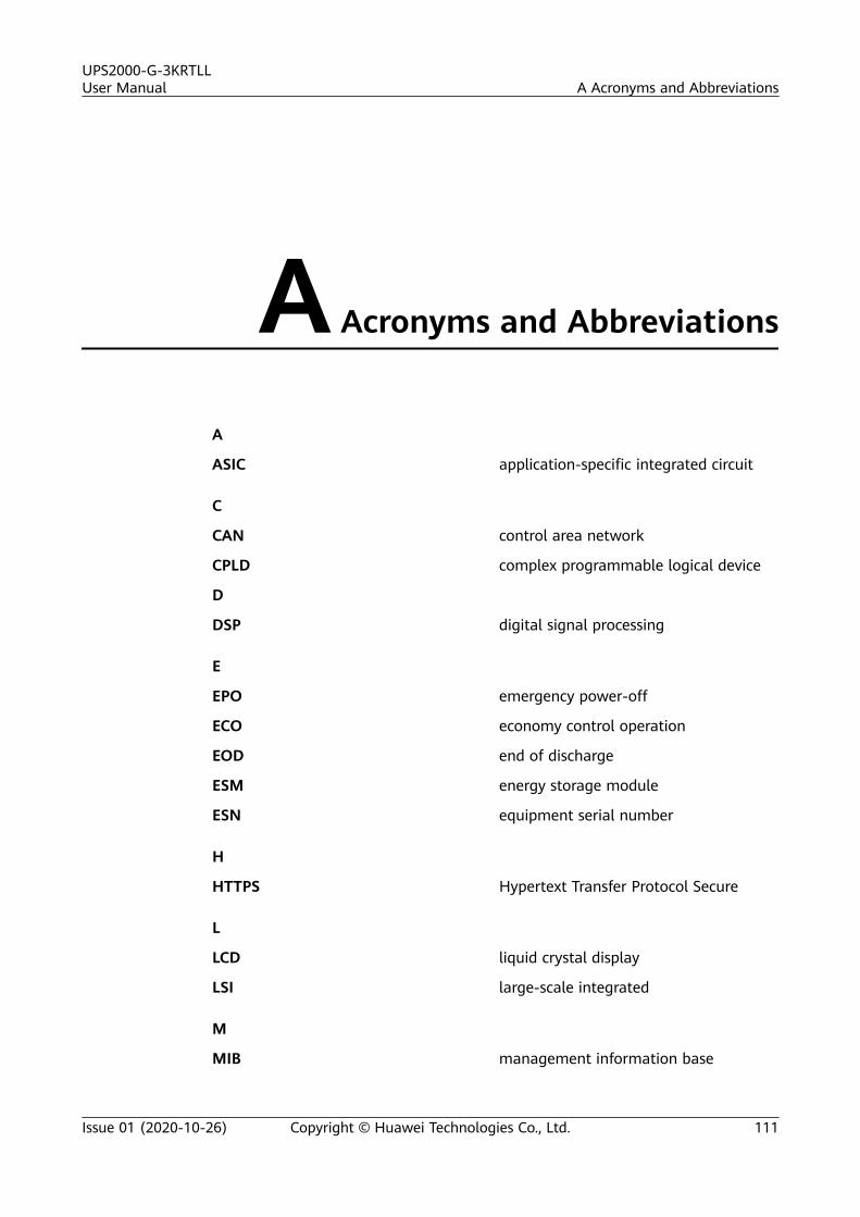
A Acronyms and Abbreviations
A
ASIC application-specific integrated circuit
C
CAN control area network
CPLD complex programmable logical device
D
DSP digital signal processing
E
EPO emergency power-off
ECO economy control operation
EOD end of discharge
ESM energy storage module
ESN equipment serial number
H
HTTPS Hypertext Transfer Protocol Secure
L
LCD liquid crystal display
LSI large-scale integrated
M
MIB management information base
UPS2000-G-3KRTLLUser Manual A Acronyms and Abbreviations
Issue 01 (2020-10-26) Copyright © Huawei Technologies Co., Ltd. 111
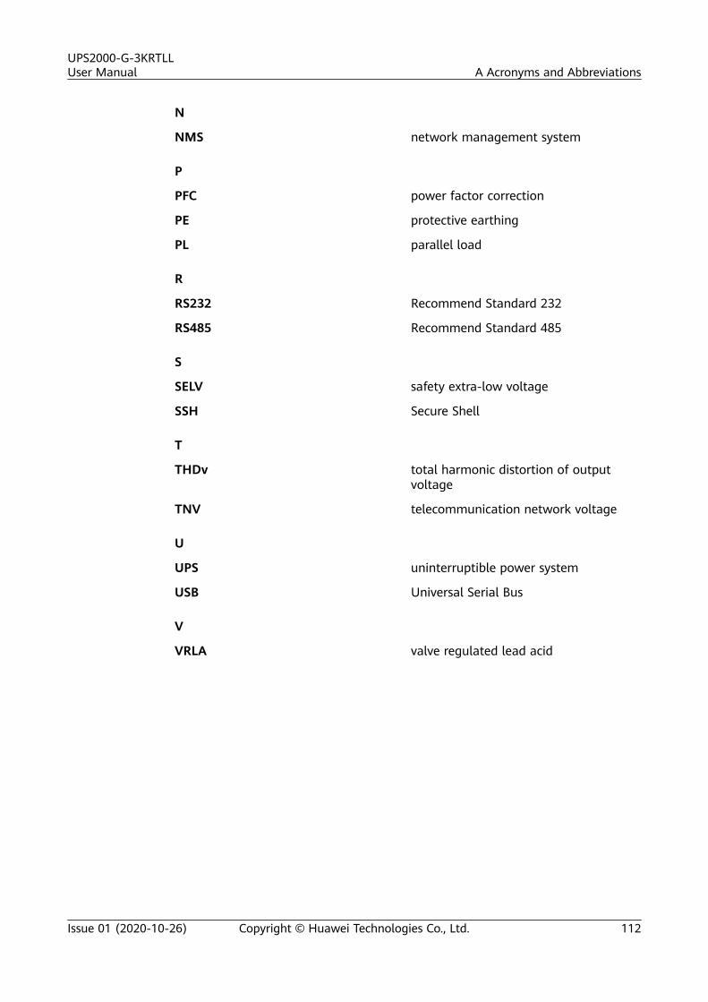
N
NMS network management system
P
PFC power factor correction
PE protective earthing
PL parallel load
R
RS232 Recommend Standard 232
RS485 Recommend Standard 485
S
SELV safety extra-low voltage
SSH Secure Shell
T
THDv total harmonic distortion of outputvoltage
TNV telecommunication network voltage
U
UPS uninterruptible power system
USB Universal Serial Bus
V
VRLA valve regulated lead acid
UPS2000-G-3KRTLLUser Manual A Acronyms and Abbreviations
Issue 01 (2020-10-26) Copyright © Huawei Technologies Co., Ltd. 112
Related Documents