Rugged Environment Minicomputer Rugged Environment Minicomputer User Manual User Manual Self Contained Single Board Computer in a Modular Small Form Factor Configuration for Demanding Applications NanoPAK ® NanoPAK ®

Welcome message from author
This document is posted to help you gain knowledge. Please leave a comment to let me know what you think about it! Share it to your friends and learn new things together.
Transcript

Rugged Environment Minicomputer
Rugged Environment Minicomputer
UserManual
UserManual
Self Contained Single Board Computerin a Modular Smal l Form Factor Conf igurat ion
for Demanding Appl icat ions
NanoPAK® NanoPAK®

S
elf C
on
ta
in
ed
S
BC
in
S
FF
C
on
fig
ura
tio
n
Na
no
PA
K® R
EM
Na
no
PA
K® R
EM
S
elf C
on
ta
in
ed
S
BC
in
S
FF
C
on
fig
ura
tio
n
Na
no
PA
K® R
EM
Na
no
PA
K® R
EM
S
elf C
on
ta
in
ed
S
BC
in
S
FF
C
on
fig
ura
tio
n
Na
no
PA
K® R
EM
Na
no
PA
K® R
EM
S
elf C
on
ta
in
ed
S
BC
in
S
FF
C
on
fig
ura
tio
n
Na
no
PA
K® R
EM
Na
no
PA
K® R
EM
S
elf C
on
ta
in
ed
S
BC
in
S
FF
C
on
fig
ura
tio
n
Na
no
PA
K® R
EM
Na
no
PA
K® R
EM
S
elf C
on
ta
in
ed
S
BC
in
S
FF
C
on
fig
ura
tio
n
Na
no
PA
K® R
EM
Na
no
PA
K® R
EM
S
elf C
on
ta
in
ed
S
BC
in
S
FF
C
on
fig
ura
tio
n
Na
no
PA
K® R
EM
Na
no
PA
K® R
EM
S
elf C
on
ta
in
ed
S
BC
in
S
FF
C
on
fig
ura
tio
n
Na
no
PA
K® R
EM
Na
no
PA
K® R
EM

Themis Computer—Rest of World5 Rue Irene Joliot-Curie38320 Eybens, FrancePhone +33 476 14 77 80Fax +33 476 14 77 89
Themis Computer—Americas and Pacific Rim47200 Bayside ParkwayFremont, CA 94538Phone (510) 252-0870Fax (510) 490-5529World Wide Web http://www.themis.com
NanoPAK® User Manual
Version 1.0— December 2012

Copyright © 2012 Themis Computer, Inc.
ALL RIGHTS RESERVED. No part of this publication may be reproduced in any form, byphotocopy, microfilm, retrieval system, or by any other means now known or hereafter invented withoutthe prior written permission of Themis Computer.
The information in this publication has been carefully checked and is believed to be accurate. However,Themis Computer assumes no responsibility for inaccuracies. Themis Computer retains the right tomake changes to this publication at any time without prior notice. Themis Computer does not assumeany liability arising from the application or use of this publication or the product(s) described herein.
RESTRICTED RIGHTS LEGEND: Use, duplication, or disclosure by the United States Governmentis subject to the restrictions set forth in DFARS 252.227-7013 (c)(1)(ii) and FAR 52.227-19.
TRADEMARKS and SERVICEMARKS
Themis® is a registered trademark of Themis Computer, Inc.
All other trademarks, servicemarks, or registered trademarks used in this publication are the property oftheir respective owners.
CE Marking
This product complies with the European EMC Directive (2004/108/EC) and the European Low VoltageSafety Directive (2006/95/EC)/.
Safety Precautions
Instructions regarding safety precautions during installation, operation, or maintenance of the equipmentare given in the section entitled “Safety Instructions” on page iv.
WARNINGS and CAUTIONS
The definitions of WARNINGS and CAUTIONS as used in this document are given in the Preface inthe section entitled “Notes, Cautions, Warnings, and Sidebars”.
NanoPAK® User Manual, Version 1.0
December 2012
Part Number: 118527-024
Themis Customer Support
North America, South America, and Pacific Rim
Telephone: 510-252-0870Fax: 510-490-5529
E-mail: [email protected] Site: http://www.themis.com

iiiThemis Computer
NanoPAK® User Manual
Version Revision History
Version 1.0.................................................................................... December 2012

ivThemis Computer
NanoPAK® User Manual Version 1.0
Safety InstructionsTo maximize user safety and ensure correct device operation, all instructions con-tained in this section should be read carefully.
• The device must be used in accordance with the instructions for use.
• The unit is completely disconnected from the power source only when thepower cord is disconnected from the power source. Therefore the power cordand its connectors must always remain easily accessible.
• The device is no longer safe to operate when
— the device has visible damage or
— the device no longer functions.
• In these cases, the device must be shut down and secured against unintentionaloperation.
• Repairs may only be carried out by a person authorized by Themis Computer.
• If extensions are made to the device, the legal stipulations and the device spec-ifications must be observed.
• The device must be switched off when removing the top cover.
Electrostatic Discharge (ESD)
A sudden discharge of electrostatic electricity can destroy static-sensitive devicesor micro-circuitry. Proper packaging and grounding techniques are necessary pre-cautions to prevent damage. Always take the following precautions:
1. Transport boards in static-safe containers such as boxes or bags.
2. Keep electrostatic-sensitive parts in their containers until they arrive at static-free stations.
3. Always be properly grounded when touching a sensitive board, component, orassembly.
Caution: It is important that the user observe all warnings and instructionsthat are on the device and contained in this manual.
vThemis Computer
NanoPAK® User Manual
4. Store electrostatic-sensitive boards in protective packaging or on conductivefoam.
Grounding Methods
Guard against electrostatic damage at workstations by following these steps:
1. Cover workstations with approved anti-static material. Provide a wrist strapconnected to a work surface and properly grounded tools and equipment.
2. Use anti-static mats, heel straps, or air ionizers to give added protection.
3. Handle electrostatic-sensitive components, boards, and assemblies by the caseor the PCB edge.
4. Avoid contact with pins, leads, or circuitry.
5. Turn off power and input signals before inserting and removing connectors ortest equipment.
6. Keep the work area free of non-conductive materials such as ordinary plastic as-sembly aids and Styrofoam.
7. Use field service tools, such as cutters, screwdrivers, and vacuums that are con-ductive.
8. Always place drives and boards PCB-assembly-side down on the foam.

viThemis Computer
NanoPAK® User Manual Version 1.0

viiThemis Computer
Table of Contents
Version Revision History ...................................................................................................... iii
Safety Instructions ................................................................................................................ iv
How to Use This Manual ................................................................................................... xvii
1. Overview and Specifications ........................................................................................ 1-1
1.1 Overview ................................................................................................................ 1-1
1.2 System Description ................................................................................................ 1-2
1.3 Configurations ....................................................................................................... 1-5
1.4 Specifications ......................................................................................................... 1-91.4.1 General Specifications ............................................................................... 1-91.4.2 Compliance ............................................................................................. 1-10
1.5 Packaging and Shipping ....................................................................................... 1-10
2. Installation and Operation ........................................................................................... 2-1
2.1 Applying Power ..................................................................................................... 2-12.1.1 Provide Adequate Cooling ......................................................................... 2-22.1.2 Configure Power ........................................................................................ 2-2
2.1.2.1 Power Button .............................................................................. 2-22.1.2.2 Sleep Mode Setting ..................................................................... 2-4
2.1.3 Useful Tools ............................................................................................... 2-5
2.2 Front Panel Indicators ............................................................................................ 2-62.2.1 Power LED ................................................................................................ 2-62.2.2 Disk Activity LED ..................................................................................... 2-72.2.3 Ethernet Activity LED ............................................................................... 2-72.2.4 Ethernet Link Status LED .......................................................................... 2-7
2.3 Input and Output .................................................................................................... 2-92.3.1 USB Ports .................................................................................................. 2-92.3.2 Serial Ports ................................................................................................. 2-9
2.3.2.1 COM A ....................................................................................... 2-92.3.2.2 COM B ...................................................................................... 2-12

viiiThemis Computer
NanoPAK® User Manual Version 1.0
2.3.3 General Purpose I/O ................................................................................. 2-122.3.4 Ethernet Port ............................................................................................ 2-132.3.5 Video Port (VGA) .................................................................................... 2-132.3.6 Storage ..................................................................................................... 2-132.3.7 HD Audio Interface ................................................................................. 2-14
2.4 Power Consumption ............................................................................................. 2-152.4.1 Current Protection .................................................................................... 2-152.4.2 Standby Power/Battery ............................................................................ 2-152.4.3 Backup Battery Replacement ................................................................... 2-18
3. InsydeH2O® BIOS Setup Utility ................................................................................. 3-1
3.1 Introduction ............................................................................................................ 3-1
3.2 Starting the BIOS Setup Utility ............................................................................. 3-23.2.1 Navigating the Utility Screens ................................................................... 3-3
3.3 Main BIOS Setup ................................................................................................... 3-43.3.1 System Overview ....................................................................................... 3-43.3.2 System Time/System Date ......................................................................... 3-53.3.3 Language .................................................................................................... 3-5
3.4 Advanced Setup ..................................................................................................... 3-63.4.1 Boot Configuration .................................................................................... 3-73.4.2 Peripherals Configuration .......................................................................... 3-83.4.3 IDE Configuration ..................................................................................... 3-93.4.4 Video Configuration ................................................................................ 3-103.4.5 USB Configuration .................................................................................. 3-113.4.6 Chipset Configuration .............................................................................. 3-12
3.4.6.1 NorthBridge Configuration ....................................................... 3-133.4.6.2 NorthBridge PCIe Configuration .............................................. 3-143.4.6.3 APU GPP Features Configuration ............................................ 3-153.4.6.4 Hudson-1 FCH Configuration .................................................. 3-163.4.6.5 SouthBridge/GPP Configuration .............................................. 3-173.4.6.6 SouthBridge PCIe Configuration .............................................. 3-183.4.6.7 SouthBridge PCIe Port Features Configuration ........................ 3-19
3.4.7 ACPI Tables/Features Control ................................................................. 3-203.4.8 CPU Related Settings ............................................................................... 3-213.4.9 AMD PBS Option .................................................................................... 3-22
3.5 Security Configuration ......................................................................................... 3-23
3.6 Power Configuration ............................................................................................ 3-24

ixThemis Computer
Table of Contents
3.6.1 Advanced CPU Control ........................................................................... 3-25
3.7 Boot Configuration .............................................................................................. 3-263.7.1 EFI Configuration .................................................................................... 3-273.7.2 Legacy Boot Device Configuration ......................................................... 3-28
3.8 Exit Menu ............................................................................................................ 3-29
4. AMI BIOS Setup Utility ............................................................................................... 4-1
4.1 Introduction ............................................................................................................ 4-14.1.1 Starting the BIOS Setup Utility ................................................................. 4-1
4.2 Main BIOS Setup ................................................................................................... 4-34.2.1 System Overview: ...................................................................................... 4-3
4.2.1.1 BIOS Information ....................................................................... 4-34.2.1.2 System Memory Information ...................................................... 4-44.2.1.3 System Time/System Date .......................................................... 4-4
4.3 Advanced Setup Configuration .............................................................................. 4-54.3.1 CPU Configuration .................................................................................... 4-64.3.2 IDE Configuration ..................................................................................... 4-74.3.3 Floppy Configuration ................................................................................. 4-94.3.4 ACPI Settings .......................................................................................... 4-10
4.3.4.1 General ACPI Configuration .................................................... 4-114.3.4.2 Advanced ACPI Configuration ................................................. 4-124.3.4.3 Chipset ACPI Configuration ..................................................... 4-13
4.3.5 AHCI Configuration ................................................................................ 4-144.3.6 Event Log Configuration ......................................................................... 4-154.3.7 Hardware Health Configuration ............................................................... 4-164.3.8 MPS Configuration .................................................................................. 4-174.3.9 SMBIOS Configuration ........................................................................... 4-184.3.10 USB Configuration .................................................................................. 4-19
4.3.10.1 USB Mass Storage Device Configuration ................................ 4-20
4.4 Advanced PCI/PnP Settings ................................................................................. 4-21
4.5 Boot Settings ........................................................................................................ 4-234.5.1 Boot Settings Configuration .................................................................... 4-24
4.6 Security Setup ...................................................................................................... 4-26
4.7 Advanced Chipset Settings .................................................................................. 4-274.7.1 North Bridge Chipset Configuration ........................................................ 4-284.7.2 South Bridge Chipset Configuration ........................................................ 4-30
xThemis Computer
NanoPAK® User Manual Version 1.0
4.8 Exit Options ......................................................................................................... 4-324.8.1 Save Changes and Exit ............................................................................ 4-324.8.2 Discard Changes and Exit ........................................................................ 4-334.8.3 Load Optimal Defaults ............................................................................. 4-334.8.4 Load Fail-Safe Defaults ........................................................................... 4-33
Appendix A. Connector Pinouts, Signals and Solder Beads ......................................... A-1
A.1 J1 Pinouts and Signals .......................................................................................... A-1
A.2 Signal Descriptions ............................................................................................... A-6
A.3 Solder Beads and Jumpers .................................................................................. A-10
A.3.1 Solder Bead Locations and Settings ....................................................... A-10
A.3.2 Jumpers ................................................................................................... A-15A.3.2.1 Jumper JP1 ............................................................................... A-15A.3.2.2 Jumper JP6 ............................................................................... A-15
Appendix B. Accessory Equipment .................................................................................B-1
B.1 NanoPAK® Development Kit ................................................................................B-1
B.2 Breakout Cable ......................................................................................................B-3
B.2.1 Serial Port Pinouts .....................................................................................B-7
B.2.2 Power Cable Pinouts ..................................................................................B-8
B.2.3 Power Button Pinout ..................................................................................B-9
B.2.4 Vbat (Standby Power) Cable Pinout. .......................................................B-10
B.2.5 Audio Cable Pinouts ................................................................................B-10
B.2.6 USB Cable Pinouts ..................................................................................B-10
B.2.7 Ethernet Cable Pinouts .............................................................................B-11
B.2.8 VGA Cable Pinouts .................................................................................B-12
B.2.9 GPIO Cable Pinouts .................................................................................B-13
Appendix C. Repackaging Instructions ...........................................................................C-1
C.1 Repackaging for Shipment .....................................................................................C-1
C.2 Packaging Components ..........................................................................................C-2
C.3 Instructions for Repackaging .................................................................................C-2
Index ................................................................................................................ Index-1
Reader Comment Card

xiThemis Computer
Table of Contents
List of Figures
Figure 1 NanoPAK® ..................................................................................................... xvii
Figure 1-1 NanoPAK® SBC.............................................................................................. 1-1
Figure 1-2 NanoPAK Ordering Information ..................................................................... 1-3
Figure 1-3 Block Diagram: NanoPAK®/AMD Processor with SATA Capability ........... 1-5
Figure 1-4 Block Diagram: NanoPAK®/AMD Processor without SATA Capability ...... 1-6
Figure 1-5 Block Diagram: NanoPAK®/Intel® Processor with SATA Capability ........... 1-7
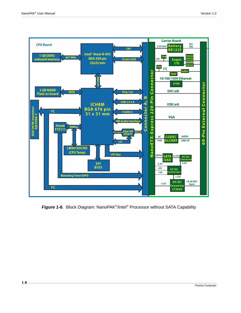
Figure 1-6 Block Diagram: NanoPAK®/Intel® Processor without SATA Capability ...... 1-8
Figure 2-1 Power Options.................................................................................................. 2-2
Figure 2-2 Power Plan Selection ....................................................................................... 2-3
Figure 2-3 Power Button Setting ....................................................................................... 2-3
Figure 2-4 Power Options Screen...................................................................................... 2-4
Figure 2-5 Sleep Setting .................................................................................................... 2-4
Figure 2-6 NanoPAK® Front Panel................................................................................... 2-6
Figure 2-7 Typical RS422 Interface Circuit .................................................................... 2-11
Figure 2-8 RS485 Full-Duplex Bus Configuration ......................................................... 2-11
Figure 2-9 RS485 Half-Duplex Bus Configuration......................................................... 2-12
Figure 2-10 GPIO diagram ................................................................................................ 2-13
Figure 2-11 Power Consumption....................................................................................... 2-15
Figure 2-12 Standby Power Diagram ................................................................................ 2-16
Figure 2-13 Jumper Locations ........................................................................................... 2-17
Figure 2-14 Backup Battery Replacement......................................................................... 2-18
Figure 3-1 Splash Screen................................................................................................... 3-2
Figure 3-2 BIOS Information Screen ................................................................................ 3-2
Figure 3-3 Setup Screen Legend ....................................................................................... 3-3
Figure 3-4 Main Setup Screen ........................................................................................... 3-4
Figure 3-5 Advanced Settings Screen ............................................................................... 3-6
xiiThemis Computer
NanoPAK® User Manual Version 1.0
Figure 3-6 Boot Configuration Settings ............................................................................ 3-7
Figure 3-7 Peripheral Configuration Settings.................................................................... 3-8
Figure 3-8 IDE Configuration Settings ............................................................................. 3-9
Figure 3-9 Video Configuration Settings ........................................................................ 3-10
Figure 3-10 USB Configuration Settings .......................................................................... 3-11
Figure 3-11 Chipset Configuration Settings ...................................................................... 3-12
Figure 3-12 NorthBridge Configuration............................................................................ 3-13
Figure 3-13 NorthBridge PCIe Configuration Settings ..................................................... 3-14
Figure 3-14 APU GPP Features Configuration Screen ..................................................... 3-15
Figure 3-15 Hudson-1 FCH Configuration Settings.......................................................... 3-16
Figure 3-16 SouthBridge/GPP Configuration Settings ..................................................... 3-17
Figure 3-17 SouthBridge PCIe Configuration Settings ..................................................... 3-18
Figure 3-18 SouthBridge PCIe Port Features Configuration Settings............................... 3-19
Figure 3-19 ACPI Tables/Features Control....................................................................... 3-20
Figure 3-20 CPU Related Settings..................................................................................... 3-21
Figure 3-21 AMD PBS Option.......................................................................................... 3-22
Figure 3-22 Security Configuration Settings..................................................................... 3-23
Figure 3-23 Power Configuration...................................................................................... 3-24
Figure 3-24 Advanced CPU Control ................................................................................. 3-25
Figure 3-25 Boot Configuration ........................................................................................ 3-26
Figure 3-26 EFI Configuration .......................................................................................... 3-27
Figure 3-27 Legacy Boot Device Configuration ............................................................... 3-28
Figure 3-28 Exit Menu ...................................................................................................... 3-29
Figure 4-1 Main Setup Screen ........................................................................................... 4-3
Figure 4-2 Advanced Settings ........................................................................................... 4-5
Figure 4-3 CPU Configuration Settings ............................................................................ 4-6
Figure 4-4 IDE Configuration Settings ............................................................................. 4-7
Figure 4-5 Floppy Configuration Settings......................................................................... 4-9
xiiiThemis Computer
Table of Contents
Figure 4-6 ACPI Settings ................................................................................................ 4-10
Figure 4-7 General ACPI Configuration Settings ........................................................... 4-11
Figure 4-8 Advanced ACPI Configuration Settings........................................................ 4-12
Figure 4-9 Chipset ACPI Configuration Settings............................................................ 4-13
Figure 4-10 AHCI Configuration Settings ........................................................................ 4-14
Figure 4-11 Event Log Configuration Settings ................................................................. 4-15
Figure 4-12 Hardware Health Configuration Settings....................................................... 4-16
Figure 4-13 MPS Configuration Settings .......................................................................... 4-17
Figure 4-14 SMBIOS Configuration Settings ................................................................... 4-18
Figure 4-15 USB Configuration Settings .......................................................................... 4-19
Figure 4-16 USB Mass Storage Device Configuration Settings ....................................... 4-20
Figure 4-17 PCI/PnP Configuration Settings .................................................................... 4-21
Figure 4-18 Boot Settings.................................................................................................. 4-23
Figure 4-19 Boot Settings Configuration .......................................................................... 4-24
Figure 4-20 Security Settings ............................................................................................ 4-26
Figure 4-21 Advanced Chipset Settings ............................................................................ 4-27
Figure 4-22 North Bridge Configuration........................................................................... 4-28
Figure 4-23 South Bridge Configuration........................................................................... 4-30
Figure 4-24 Exit Options Screen ....................................................................................... 4-32
Figure A-1 NanoPAK® Front Panel.................................................................................. A-1
Figure A-2 69-pin Connector J1........................................................................................ A-2
Figure A-3 Carrier Board Solder Bead Locations ........................................................... A-10
Figure A-4 Carrier Board Jumper Locations................................................................... A-15
Figure B-1 NanoPAK® Development Kit.......................................................................... B-1
Figure B-2 Baseboard (Cold Plate) .................................................................................... B-2
Figure B-3 Non-SATA Breakout Cable............................................................................. B-3
Figure B-4 SATA Break Out Cable ................................................................................... B-5
Figure B-5 J1 Plug Pin Diagram ........................................................................................ B-7

xivThemis Computer
NanoPAK® User Manual Version 1.0
Figure B-6 COM A and COM B Serial Connectors .......................................................... B-7
Figure B-7 Power Connector.............................................................................................. B-9
Figure B-8 Vbat Connector .............................................................................................. B-10
Figure B-9 GBE Connector Pinout .................................................................................. B-11
Figure B-10 VGA Connector ............................................................................................. B-12
Figure B-11 GPO Connector Pins ...................................................................................... B-13
Figure B-12 GPI Connector Pins ....................................................................................... B-14
Figure C-1 Order of Assembly........................................................................................... C-3
List of Tables
Table 1-1 NanoPAK® Features........................................................................................ 1-4
Table 1-2 NanoPAK® Specifications............................................................................... 1-9
Table 1-3 NanoPAK® Compliance Specifications ....................................................... 1-10
Table 2-1 Power LED States ............................................................................................ 2-6
Table 2-2 Ethernet Link Status LED States ..................................................................... 2-7
Table 2-3 COM A Modes and Signals ............................................................................. 2-9
Table 2-4 COM A Solder Bead Settings Matrix ............................................................ 2-10
Table 2-5 Mode Terminations........................................................................................ 2-10
Table 2-6 MIC/LINE Audio Settings............................................................................. 2-14
Table 2-7 External Standby Voltage Settings ................................................................ 2-16
Table A-1 J1 Connector Pinouts ..................................................................................... A-2
Table A-2 Signal Descriptions ........................................................................................ A-6
Table A-3 SATA Signal Descriptions............................................................................. A-8
Table A-4 NON-SATA Signal Descriptions................................................................... A-9
Table A-5 Solder Bead Settings .................................................................................... A-11
Table A-6 Battery/LED Card Solder Bead Settings ..................................................... A-14
Table A-7 Battery/LED Jumper Settings ...................................................................... A-16
Table B-1 Breakout Cable Connectors, Non-SATA........................................................ B-4

xvThemis Computer
Table of Contents
Table B-2 Breakout Cable Connectors, SATA................................................................ B-5
Table B-3 Serial Port Pinouts .......................................................................................... B-8
Table B-4 Power Cable Pinouts ....................................................................................... B-8
Table B-5 Power Button Pinouts ..................................................................................... B-9
Table B-6 Vbat (Standby Power) Cable Pinouts ........................................................... B-10
Table B-7 Audio Pinouts ............................................................................................... B-10
Table B-8 USB Cable Pinouts ....................................................................................... B-10
Table B-9 GBE Cable Pinouts ....................................................................................... B-11
Table B-10 VGA Cable Pinouts ...................................................................................... B-12
Table B-11 GPI and GPO Cable Pinouts ......................................................................... B-14

xviThemis Computer
NanoPAK® User Manual Version 1.0

xviiThemis Computer
How to Use This Manual
This document, entitled NanoPAK® User Manual, provides instructions on how toinstall, configure, and power up the NanoPAK® (see Figure 1).
The NanoPAK® is a self-contained Single Board Computer (SBC) module based onthe COMExpress® boards in an enclosure designed to withstand high temperatureand high vibration environments in applications requiring light weight and smallsize.
An overview of NanoPAK® design and specifications is given in Chapter 1, "Over-
Figure 1. NanoPAK®
PrefaceSection
NanoPAK® User Manual Version 1.0
xviiiThemis Computer
view and Specifications", of this manual.
Themis Computer values its customer comments and opinions; therefore, a “ReaderComment Card” is located at the end of this manual for your use. Please take thetime to fill out this card with any comments concerning Themis products and ser-vices, and return it to Themis Computer. Your comments may also be forwarded toThemis by sending email to [email protected].
Before you begin, carefully read each of the procedures in this manual. Serious dam-age can be caused by improper handling of the equipment.
Intended AudienceThis manual is written for system integrators and programmers. It contains all neces-sary information for installation and configuration of the NanoPAK® and assumesthe BIOS program code is installed in the system Flash memory.
Although all specific hardware features are described in the installation manual, pro-grammers wishing to write code for the NanoPAK® without the benefit of an operat-ing system or real-time kernel will require additional data sheets.
Unpacking
Remove the NanoPAK® and accessories from the shipping container and check thecontents against the packing list. Be certain to observe industry-standard ESD pro-tection procedures when handling static-sensitive components. The package shouldinclude all elements of your order.
Please report any shipping discrepancies to the Themis Computer Customer Supportgroup immediately: [email protected] or 1-510-252-0870.
Caution: The NanoPAK® contains statically sensitive components. Industry-stan-dard antistatic measures must be observed when removing the equipment from itsshipping container and during any subsequent handling. A wrist strap providesgrounding for static electricity between your body and the chassis of the systemunit.
How to Use This Manual
Chapter Overview
xixThemis Computer
Chapter OverviewThe chapters and appendices of this manual are briefly outlined as follows:
• Chapter 1 provides a brief overview of the NanoPAK®, along with its System,Environmental, and Power specifications.
• Chapter 2 provides information helpful for installation and configuration of theNanoPAK® for your particular environment and application.
• Chapter 3 provides instructions for setting up and configuring the BIOS forthose systems with InsydeH2O® BIOS installed, primarily those with AMDCPUs.
• Chapter 4 provides instructions for setting up and configuring the BIOS forthose systems with AMI BIOS installed, primarily those with Intel® CPUs.
• Appendix A provides pinouts and signal descriptions for the connector.
• Appendix B provides information about accessory equipment.
• Appendix C provides information about repackaging the equipment for returnto the manufacturer.
Notes, Cautions, Warnings, and SidebarsThe following icons and formatted text are included in this document for the reasonsdescribed:
Note: A note provides additional information concerning the procedure or actionbeing described.
Caution: A caution describes a procedure or action that may result in damage tothe equipment. This may involve—but is not restricted to—heavy equipment orsharp objects. To reduce the risk, follow the instructions accompanying this symbol.

NanoPAK® User Manual Version 1.0
xxThemis Computer
Website InformationThemis Computer corporate and product information may be accessed on the WorldWide Web by browsing the website http://www.themis.com.
Your Comments are WelcomeWe are interested in improving our documentation and welcome your comments andsuggestions. You can email your comments to us at [email protected] include the document part number in the subject line of your email: 118527-024.
Warning: A warning describes a procedure or action that may cause injury or deathto the operator as a result of hazardous voltages. To reduce the risk, follow the in-structions accompanying this symbol.
Sidebar: A “sidebar” adds detail to the section within which it is placed,but is not absolutely vital to the description or procedure of the section.

1-1Themis Computer
1NanoPAK®
Overview and Specifications
1.1 Overview
The NanoPAK® (see Figure 1-1 below) is a self-contained Single Board Computer(SBC) system designed for applications requiring small size and light weight in hightemperature, high vibration environments. It is ideal for remote controlled air andground vehicles employed in hazardous conditions.
Figure 1-1. NanoPAK® SBC
General Section
Chapter
1-2Themis Computer
NanoPAK® User Manual Version 1.0
1.2 System Description
The NanoPAK® is a self-contained SBC module containing a carrier board and aCPU mezzanine card using the industry standard COMExpress® form factor andType 1 pin assignments. The CPU mezzanine card is mounted on the carrier board,which interfaces the processor module with the 69-pin external connector and pro-vides support including additional I/O, buffering, FLASH, etc. The IO logic on thecarrier board includes an HD Audio port provided by an ALC889 codec, two nativeserial ports, and a Solid-State Disk drive attached to one of the three SATA ports ofthe SBC, which can serve as a boot device for the system. The CPU mezzanine carduses one of the processors listed in Figure 1-2. For connectivity to I/O devices, theCPU will be paired with a PCH as listed in Figure 1-2. The BIOS is contained in aflash device connected to the PCH over the SPI interface. All power, control, man-agement, and I/O signals go through the external 69-pin connector.
The system is described by its complete Part Number, as in the following example,according to the description in Figure 1-2, NanoPAK Ordering Information, on page1-3. For instance, a system with a part number of TSY-215NP-322-NNANVN hascomponents as follows, (the part number may often be shortened, as in TSY-215NP):
TSY- 2 xx NP-xxx-XXXXXX
TSY- 2 15 NP-322-NNANVN
215 = AMD Fusion - T56N CPU / A55E3 = 64GB flash on SBC Module2 = 32GB flash on Carrier Board2 = 2GB RAM on SBC ModuleN = Line In (Audio Input Option)N = Internal Removable Battery HolderA = RS232 Serial Port TTYA OptionN = Non-sealed connectorsV = SATA 2GPI/2GPON= DDC for VGA interface (I2C Bus Option)
Complete Part Number descriptions are given in Figure 1-2. These represent thestandard configurations. Please consult the factory for other configurations.

1—Overview and Specifications
System Description
1-3Themis Computer
Figure 1-2. NanoPAK Ordering Information
202 = Intel® Atom - N 455 CPU / ICH8M211 = AMD Fusion - T40R C PU / A55E212 = AMD Fusion - T40E CPU / A55E213 = AMD Fusion - T40N CPU / A55E214 = AMD Fusion - T48N CPU / A55E215 = AMD Fusion - T56N CPU / A55E
0 = No Flash1 = 16GB flash2 = 32GB flash3 = 64GB flash4 = 128GB flash8 = 1GB fla sh9 = 2GB fla sh
0 = No flash3 - FLA SH ON CARRIER BOARD
2 - FLA SH ON SBC MODULE
1 = 16GB2 = 32GB3 = 64GB4 = 128GB4 - RAM on SBC MODULE1 = 1GB2 = 2GB4 = 4GB5 - AUDIO input OPTIONM = Microphone InN = Line In6 - BATTERY OPTION0 = No batteryR = External Vbat (wide range 9V to 36V )V = Exte rnal battery 3VN = Inte rna l removable batteryB = Internal solde red-down battery7 - SERIAL PORT TTY AA = RS232 N = RS-422B = RS-485 Ha lf-duplex endpointC = RS-485 Full-duple x endpointD = RS-485 Half-duplex midpointE = RS-485 Full-duplex midpoint8 - SEALING OPTIONN = non-seale dS = seale d9 - SATA IIN = No SATAV = SATA 2GPI/2GPO10 - I2C BUSN = DDC for VGA interfaceS = SMBbusU = Use r I2C
1 - CPU on SBC MODULE
TSY - 2 xx NP - x x x - x x x x x x

1-4Themis Computer
NanoPAK® User Manual Version 1.0
Table 1-1 lists major features of the NanoPAK®
Table 1-1. NanoPAK® Features
Parameter Description
Processor See Figure 1-2
Memory See Figure 1-2
Ethernet port Single 10/100/1000 MB Ethernet
LEDs
Power Disk Activity GBe Link GBe Activity
I/O Ports
4 USB 2.0 ports 2 Serial ports 4 General Purpose Inputs (non-SATA ver.) 4 General Purpose Outputs (non-SATA ver.) 2 General Purpose Inputs (SATA ver.) 2 General Purpose Outputs (SATA ver.)
Video 1 VGA port
BIOS 2MB BIOS Flash InsydeH2O® BIOS for AMD Processors AMI BIOS for Intel® Processors
Audio 1 HD Audio port, ALC889 CODEC Line In or MIC In Line Out
I2C I2C Interface
Temp Over-Temp Monitor
TPM Standard
Battery backup Internal (BR1225/48mAh) or External option

1—Overview and Specifications
1-5Themis Computer
1.3 Configurations
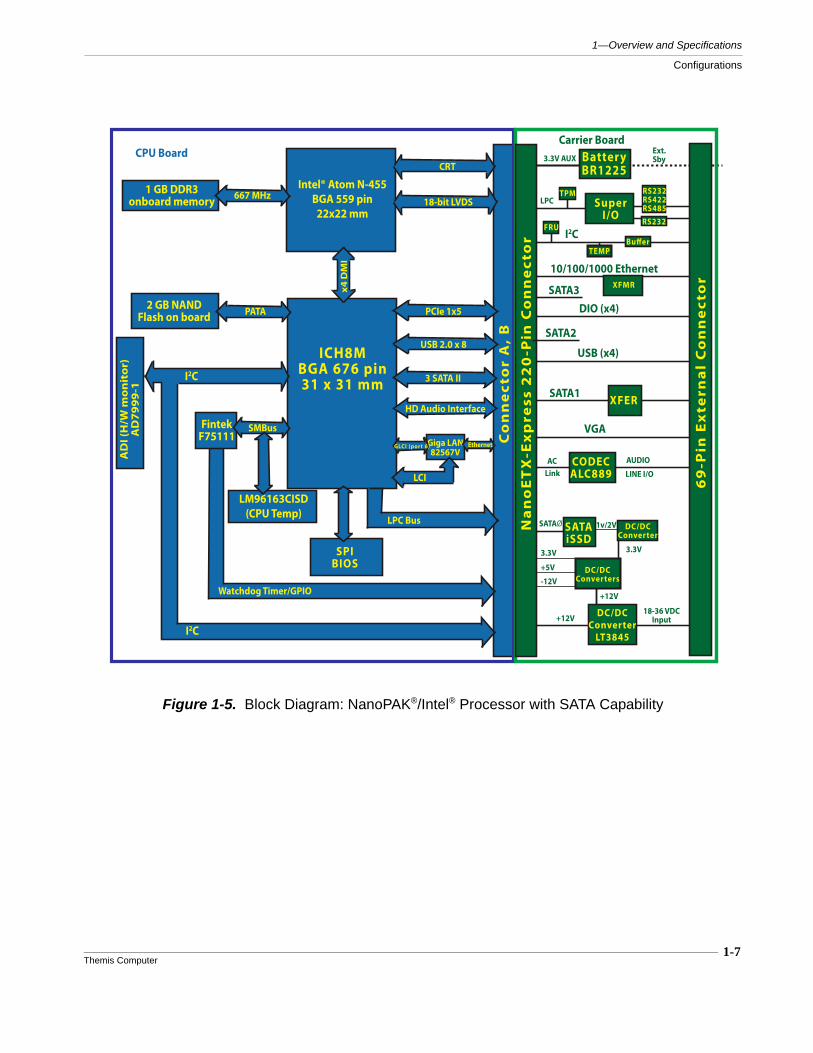
There are basically four configurations of the NanoPAK®: The AMD processors withand without SATA capability, and the Intel® processors with and without SATA capa-bility. Figure 1-3 illustrates a representative block diagram of the NanoPAK® withAMD processor and SATA capability. Figure 1-4 shows an AMD processor withoutSATA capability. Figure 1-5 and Figure 1-6 illustrate the NanoPAK® with Intel® pro-cessors with and without SATA, respectively.
Figure 1-3. Block Diagram: NanoPAK®/AMD Processor with SATA Capability
AMD EMBEDDED
PROBEtest pads for Debug
Hudson-E1 FCH605 Ball BGA 23 x 23 mm
Co
nn
ect
or
A,
B
2 GB DDR3
GIGABITETHERNET
GPP1
SPIROM
SP
I I/
F24-bit LVDS x2
x4 U
MI
AMD TSI
APUFAN
SandiskiSSD
I2CSMBus/
VGA I/F
PCIe Gen2
PCIe GEN2 4x1
AMD FT1 APUOntario, U1
413 Ball BGA19 x19 mm
USB 2.0 x 5
SATA II, 4x
HD Audio I/F
GPIOs x8
LPC I/F
Processor Board800-1066MT/s
SATAII, 1x
Display Port X2Single Channel
DDR3
VGA DAC
4x1 PCIe Gen2 GPP
SPI I/F
HW Monitor I/F
AZALIA HD Audio
JTAG
DX11 IGP1 x4 UMI-LINK
Gen 1
U7
PCIe Gen2 I/F Port 2 ,x1
USB 2.0 (12) + 1.1 (2)
SATA II (6 ports total)
INT. CLKGEN
LPC I/FPCI I/F
VGA
XFERSATA1
USB (x4)
DIO (x4)
10/100/1000 Ethernet
I2C
69
-Pin
Ex
tern
al
Co
nn
ect
or
+12V DC/DCConverter
LT3845
SuperI/O
Carrier Board
CODECALC889
SATAiSSD
AUDIO
LINE I/O
DC/DCConverters
SATAØ
ACLink
3.3V
18-36 VDCInput
3.3V AUX
RS232
Na
no
ET
X-E
xp
ress
22
0-P
in C
on
ne
cto
r
BatteryBR1225
LPCRS232RS422RS485
Buffer
FRU
Ext.Sby
SATA2
SATA3
TPM
TEMP
+12V
3.3V
-12V
+5V
DC/DCConverter
1v/2V
XFMR

1-6Themis Computer
NanoPAK® User Manual Version 1.0
Figure 1-4. Block Diagram: NanoPAK®/AMD Processor without SATA Capability
AMD EMBEDDED
PROBEtest pads for Debug
Hudson-E1 FCH605 Ball BGA 23 x 23 mm
Co
nn
ect
or
A,
B
2 GB DDR3
GIGABITETHERNET
GPP1
SPIROM
SP
I I/
F
24-bit LVDS x2
x4 U
MI
AMD TSI
APUFAN
SandiskiSSD
I2CSMBus/
VGA I/F
PCIe Gen2
PCIe GEN2 4x1
AMD FT1 APUOntario, U1
413 Ball BGA19 x19 mm
USB 2.0 x 5
SATA II, 4x
HD Audio I/F
GPIOs x8
LPC I/F
Processor Board800-1066MT/s
SATAII, 1x
Display Port X2Single Channel
DDR3
VGA DAC
4x1 PCIe Gen2 GPP
SPI I/F
HW Monitor I/F
AZALIA HD Audio
JTAG
DX11 IGP1 x4 UMI-LINK
Gen 1
U7
PCIe Gen2 I/F Port 2 ,x1
USB 2.0 (12) + 1.1 (2)
SATA II (6 ports total)
INT. CLKGEN
LPC I/FPCI I/F
VGA
USB (x4)
DIO (x8)
10/100/1000 Ethernet
I2C
69
-Pin
Ex
tern
al
Co
nn
ect
or
+12V DC/DCConverter
LT3845
SuperI/O
Carrier Board
CODECALC889
SATAiSSD
AUDIO
LINE I/O
DC/DCConverter
SATAØ
ACLink
3.3V
18-36 VDCInput
3.3V AUX
RS232
Na
no
ET
X-E
xp
ress
22
0-P
in C
on
ne
cto
r
BatteryBR1225
LPCRS232RS422RS485
Buffer
FRU
Ext.Sby
TPM
TEMP
1v/2V
DC/DCConverters
+12V
3.3V
-12V
+5V
XFMR
1-7Themis Computer
1—Overview and Specifications
Configurations
Figure 1-5. Block Diagram: NanoPAK®/Intel® Processor with SATA Capability
LM96163CISD(CPU Temp)
1 GB DDR3onboard memory
AD
I (H
/W m
on
ito
r)A
D79
99-1
ICH8MBGA 676 pin31 x 31 mm
Intel® Atom N-455BGA 559 pin22x22 mm
SPIBIOS
Co
nn
ect
or
A,
B
18-bit LVDS
x4 D
MI
I2C
I2C
Watchdog Timer/GPIO
FintekF75111
2 GB NANDFlash on board PATA
SMBus
CRT
667 MHz
LPC Bus
Giga LAN82567V
LCI
GLCI (port 6) Ethernet
PCIe 1x5
USB 2.0 x 8
3 SATA II
HD Audio Interface
CPU Board
VGA
XFERSATA1
USB (x4)
DIO (x4)
10/100/1000 Ethernet
I2C
69
-Pin
Ex
tern
al
Co
nn
ect
or
+12V DC/DCConverter
LT3845
SuperI/O
Carrier Board
CODECALC889
SATAiSSD
AUDIO
LINE I/O
DC/DCConverters
SATAØ
ACLink
3.3V
18-36 VDCInput
3.3V AUX
RS232
Na
no
ET
X-E
xp
ress
22
0-P
in C
on
ne
cto
r
BatteryBR1225
LPCRS232RS422RS485
Buffer
FRU
Ext.Sby
SATA2
SATA3
TPM
TEMP
+12V
3.3V
-12V
+5V
DC/DCConverter
1v/2V
XFMR
1-8Themis Computer
NanoPAK® User Manual Version 1.0
Figure 1-6. Block Diagram: NanoPAK®/Intel® Processor without SATA Capability
LM96163CISD(CPU Temp)
1 GB DDR3onboard memory
AD
I (H
/W m
on
ito
r)A
D79
99-1
ICH8MBGA 676 pin31 x 31 mm
Intel® Atom N-455BGA 559 pin22x22 mm
SPIBIOS
Co
nn
ect
or
A,
B
18-bit LVDS
x4 D
MI
I2C
I2C
Watchdog Timer/GPIO
FintekF75111
2 GB NANDFlash on board PATA
SMBus
CRT
667 MHz
LPC Bus
Giga LAN82567V
LCI
GLCI (port 6) Ethernet
PCIe 1x5
USB 2.0 x 8
3 SATA II
HD Audio Interface
CPU Board
VGA
USB (x4)
DIO (x8)
10/100/1000 Ethernet
I2C
69
-Pin
Ex
tern
al
Co
nn
ect
or
+12V DC/DCConverter
LT3845
SuperI/O
Carrier Board
CODECALC889
SATAiSSD
AUDIO
LINE I/O
DC/DCConverter
SATAØ
ACLink
3.3V
18-36 VDCInput
3.3V AUX
RS232
Na
no
ET
X-E
xp
ress
22
0-P
in C
on
ne
cto
r
BatteryBR1225
LPCRS232RS422RS485
Buffer
FRU
Ext.Sby
TPM
TEMP
1v/2V
DC/DCConverters
+12V
3.3V
-12V
+5V
XFMR
1-9Themis Computer
1—Overview and Specifications
1.4 Specifications
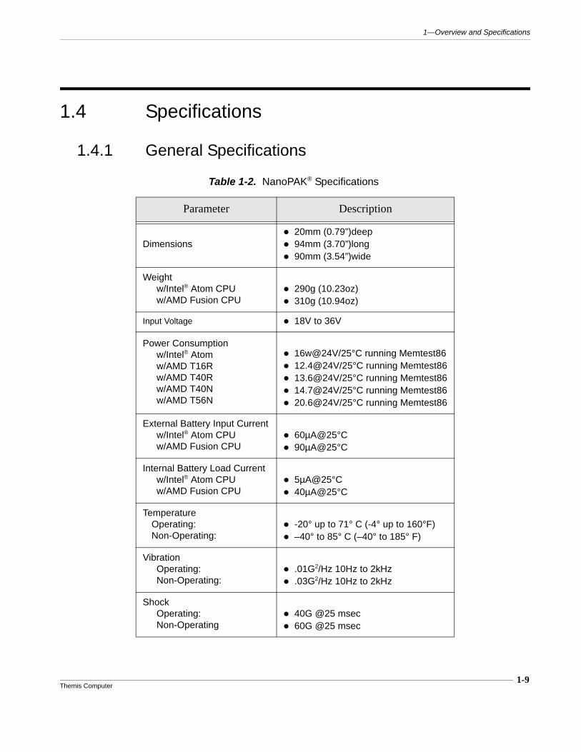
1.4.1 General Specifications
Table 1-2. NanoPAK® Specifications
Parameter Description
Dimensions 20mm (0.79”)deep 94mm (3.70”)long 90mm (3.54”)wide
Weightw/Intel® Atom CPUw/AMD Fusion CPU
290g (10.23oz) 310g (10.94oz)
Input Voltage 18V to 36V
Power Consumptionw/Intel® Atomw/AMD T16Rw/AMD T40Rw/AMD T40Nw/AMD T56N
16w@24V/25°C running Memtest86 12.4@24V/25°C running Memtest86 13.6@24V/25°C running Memtest86 14.7@24V/25°C running Memtest86 20.6@24V/25°C running Memtest86
External Battery Input Currentw/Intel® Atom CPUw/AMD Fusion CPU
60µA@25°C 90µA@25°C
Internal Battery Load Currentw/Intel® Atom CPUw/AMD Fusion CPU
5µA@25°C 40µA@25°C
Temperature Operating: Non-Operating:
-20° up to 71° C (-4° up to 160°F) –40° to 85° C (–40° to 185° F)
VibrationOperating: Non-Operating:
.01G2/Hz 10Hz to 2kHz .03G2/Hz 10Hz to 2kHz
ShockOperating: Non-Operating
40G @25 msec 60G @25 msec
1-10Themis Computer
NanoPAK® User Manual Version 1.0
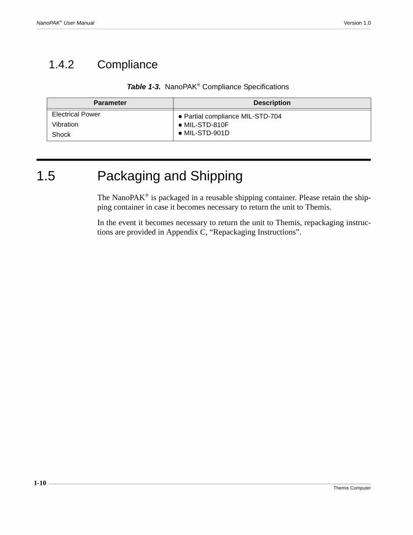
1.4.2 Compliance
1.5 Packaging and Shipping
The NanoPAK® is packaged in a reusable shipping container. Please retain the ship-ping container in case it becomes necessary to return the unit to Themis.
In the event it becomes necessary to return the unit to Themis, repackaging instruc-tions are provided in Appendix C, “Repackaging Instructions”.
Table 1-3. NanoPAK® Compliance Specifications
Parameter Description
Electrical Power
Vibration
Shock
Partial compliance MIL-STD-704 MIL-STD-810F MIL-STD-901D

2-1Themis Computer
2RES-31XR3
2
Installation and Operation
This chapter provides detailed information about the NanoPAK® installation, operat-ing status indications, and input/output ports.
2.1 Applying Power
The NanoPAK® requires an input voltage between +18 and +36 VDC. Voltage isconverted to +12VDC, -12VDC, +3.3VDC and +5VDC. These voltages are presenton the power rails as long as input voltage is applied.
Caution: When the I/O cable is attached, if the power is already applied to thepower contacts, power will be applied to the system. Before connecting the I/O Ca-ble, insure that no power is applied to the power contacts. Take care to apply powerafter the I/O Cable is attached. Attaching the cable with power on the contacts couldcause damage to the system
2
Installation Section
Chapter
NanoPAK® User Manual Version 1.0
2-2Themis Computer
2.1.1 Provide Adequate Cooling
2.1.2 Configure Power
It may be necessary to configure the power settings for the operating system in use,to configure the Power Button feature, and to either provide for, or avoid, the proces-sor going into sleep mode. In either case, the user should check these settings todetermine if they are correct for the use intended. Themis recommends the follow-ing settings.
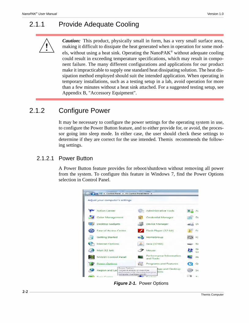
2.1.2.1 Power Button
A Power Button feature provides for reboot/shutdown without removing all powerfrom the system. To configure this feature in Windows 7, find the Power Optionsselection in Control Panel.
Caution: This product, physically small in form, has a very small surface area,making it difficult to dissipate the heat generated when in operation for some mod-els, without using a heat sink. Operating the NanoPAK® without adequate coolingcould result in exceeding temperature specifications, which may result in compo-nent failure. The many different configurations and applications for our productmake it impracticable to supply one standard heat dissipating solution. The heat dis-sipation method employed should suit the intended application. When operating intemporary installations, such as a testing setup in a lab, avoid operation for morethan a few minutes without a heat sink attached. For a suggested testing setup, seeAppendix B, "Accessory Equipment".
Figure 2-1. Power Options
2-3Themis Computer
2—Installation and Operation
Applying Power
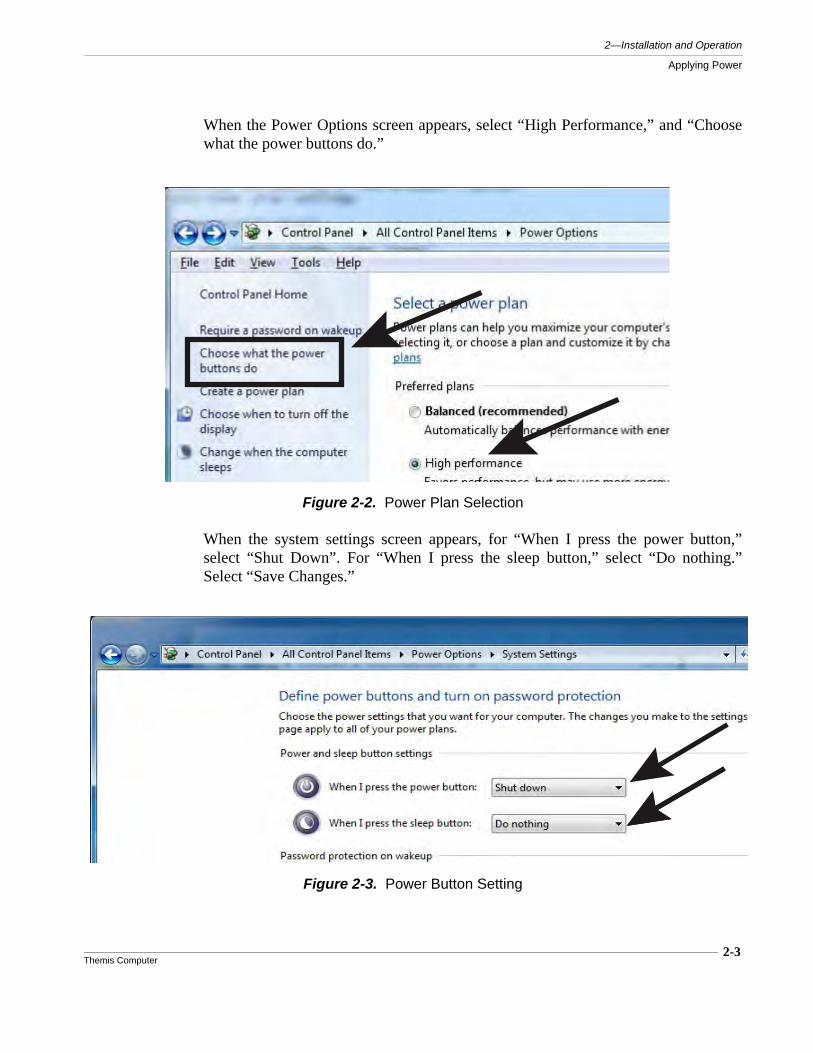
When the Power Options screen appears, select “High Performance,” and “Choosewhat the power buttons do.”
When the system settings screen appears, for “When I press the power button,”select “Shut Down”. For “When I press the sleep button,” select “Do nothing.”Select “Save Changes.”
Figure 2-2. Power Plan Selection
Figure 2-3. Power Button Setting
2-4Themis Computer
NanoPAK® User Manual Version 1.0
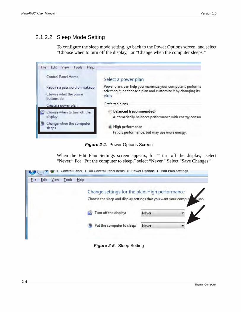
2.1.2.2 Sleep Mode Setting
To configure the sleep mode setting, go back to the Power Options screen, and select“Choose when to turn off the display,” or “Change when the computer sleeps.”
When the Edit Plan Settings screen appears, for “Turn off the display,” select“Never.” For “Put the computer to sleep,” select “Never.” Select “Save Changes.”
Figure 2-4. Power Options Screen
Figure 2-5. Sleep Setting

2-5Themis Computer
2—Installation and Operation
Applying Power
2.1.3 Useful Tools
The following tools will be handy for securing the cable to the connector and forremoving the front panel to replace the internal battery:
• One (1) .050 in., (H1.3 European), hex wrench for the 69-pin connector.
• One (1) 3.5 mm socket driver for the jack screws in the connector.
• One (1) No. 1 Phillips-head screwdriver.

2-6Themis Computer
NanoPAK® User Manual Version 1.0
2.2 Front Panel Indicators
The front panel of the NanoPAK® has 4 LED indicators: Power LED (Green, Left),Disk LED (RED), Ethernet Link Activity LED (Yellow), and Ethernet Link StatusLED (Green, right).
2.2.1 Power LED
When power is ON and the unit is running in normal mode, the Power LED is ON(solid green), otherwise the Power LED is OFF if power is not applied, or blinkingwhen in a sleep state, at a rate that depends on the type of sleep state (see Table 2-1).
Figure 2-6. NanoPAK® Front Panel
Table 2-1. Power LED States
System State Blink Rate
Normal ON mode ON Steady Green
Normal OFF mode OFF
State S3 asserted, S5 deasserted Long blink (ON 1s, OFF 1s)(Green)
States S3 and S5 assertedLong, Short blinks (ON 1s, OFF 1s, ON ½s, OFF 1s)(Green)

2-7Themis Computer
2—Installation and Operation
Front Panel Indicators
2.2.2 Disk Activity LED
The Disk Activity LED (RED) indicates activity, (read or write), to or from the car-rier card SSD storage device (random length blinks).
2.2.3 Ethernet Activity LED
The Ethernet Activity LED (Yellow) indicates traffic on the Ethernet link (randomlength blinks).
2.2.4 Ethernet Link Status LED
The Ethernet Link Status LED (Green) is OFF when no Ethernet link is established,and blinks ON when a link is established at a rate that indicates the link speed. (Thespeeds available are dependent on the type of CPU installed). See Table 2-2.
State S3 deasserted, S5 assertedShort blink (ON ½s, OFF 1s)(Green)
Table 2-1. Power LED States (Continued)
System State Blink Rate
Table 2-2. Ethernet Link Status LED States
Ethernet Link Speed
Blink Rate
10 Mbits/sLong, Short blinks (ON 1.2s, OFF 0.3s, ON 0.3s, OFF 0.3s)
100Mbits/sLong, Short, Short blinks (ON 1.2s, OFF 0.3s, ON 0.3s, OFF 0.3s, ON 0.3s, OFF 0.3s)
1000Mbits/sLong, Short, Short, Short blinks (ON 1.2s, OFF 0.3s, ON 0.3s, OFF 0.3s, ON 0.3s, OFF 0.3s, ON 0.3s, OFF 0.3s)
2-8Themis Computer
NanoPAK® User Manual Version 1.0
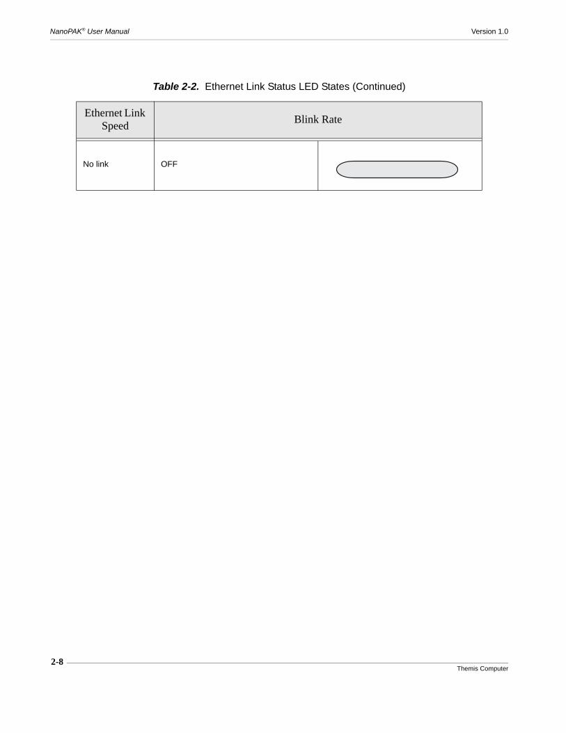
No link OFF
Table 2-2. Ethernet Link Status LED States (Continued)
Ethernet Link Speed
Blink Rate
2-9Themis Computer
2—Installation and Operation
2.3 Input and Output
2.3.1 USB Ports
Four USB 2.0 ports are provided. USB0 and USB1 support a greater current loadthan allowed by the USB standard. The peripheral attached to these ports may drawa maximum 2A current instead of the usual 500mA, but only temporarily, and maynot be sustained. USB2 and USB3 have standard current limitation of 500mA.
2.3.2 Serial Ports
Two native legacy serial ports from x86 architecture are available on the 69-pin IOconnector.
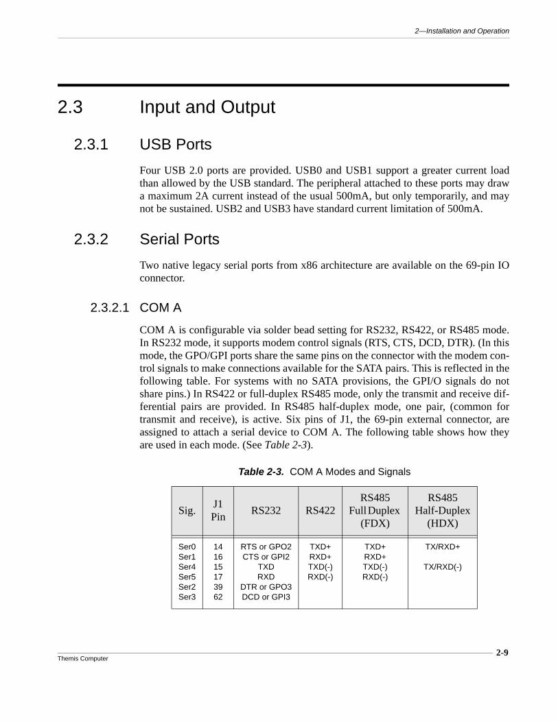
2.3.2.1 COM A
COM A is configurable via solder bead setting for RS232, RS422, or RS485 mode.In RS232 mode, it supports modem control signals (RTS, CTS, DCD, DTR). (In thismode, the GPO/GPI ports share the same pins on the connector with the modem con-trol signals to make connections available for the SATA pairs. This is reflected in thefollowing table. For systems with no SATA provisions, the GPI/O signals do notshare pins.) In RS422 or full-duplex RS485 mode, only the transmit and receive dif-ferential pairs are provided. In RS485 half-duplex mode, one pair, (common fortransmit and receive), is active. Six pins of J1, the 69-pin external connector, areassigned to attach a serial device to COM A. The following table shows how theyare used in each mode. (See Table 2-3).
Table 2-3. COM A Modes and Signals
Sig.J1 Pin
RS232 RS422RS485
Full Duplex (FDX)
RS485Half-Duplex
(HDX)
Ser0Ser1Ser4Ser5Ser2Ser3
141615173962
RTS or GPO2CTS or GPI2
TXDRXD
DTR or GPO3DCD or GPI3
TXD+RXD+TXD(-)RXD(-)
TXD+RXD+TXD(-)RXD(-)
TX/RXD+
TX/RXD(-)

NanoPAK® User Manual Version 1.0
2-10Themis Computer
The selection between RS232, RS422, and RS485 modes is done through a combi-nation of solder bead settings, as indicated in Table 2-4.
When the differential mode is chosen, it is necessary to “insert” a parallel termina-tion, as indicated in Table 2-5.
See Table A-5, "Solder Bead Settings," on page A-11 of Appendix A for furtherdetails.
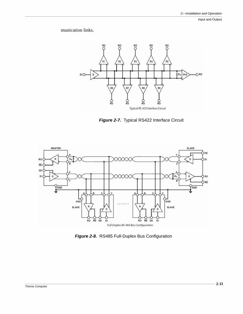
RS485 mode is designed for multipoint communication and can run either in half-duplex or full-duplex mode. When the half-duplex mode is selected, the transmitterenable signal is controlled by the TXD TTL signal from the serial controller. Thefollowing figures illustrate the typical network topology for RS422 and RS485 com-
Table 2-4. COM A Solder Bead Settings Matrix
ModeSolder Beads Setting
SB2 SB3 SB7 SB8 SB9
RS232 2-3 2-3 ON OFF OFF
RS422 2-3 2-3 OFF ON OFF
RS485
HALF-DUPLEX ENDPOINT 1-2 1-2 OFF OFF ON
FULL-DUPLEX ENDPOINT 2-3 2-3 OFF ON ON
HALF-DUPLEX MIDPOINT 1-2 1-2 OFF OFF OFF
FULL-DUPLEX MIDPOINT 2-3 2-3 OFF OFF OFF
Table 2-5. Mode Terminations
Mode Termination
RS232 NONE
RS422 One (RX)
RS485
HALF-DUPLEX ENDPOINT One (Common RX and TX)
FULL-DUPLEX ENDPOINT Two (RX and TX)
MIDPOINT NONE
2—Installation and Operation
Input and Output
2-11Themis Computer
munication links.
Figure 2-7. Typical RS422 Interface Circuit
Figure 2-8. RS485 Full-Duplex Bus Configuration
2-12Themis Computer
NanoPAK® User Manual Version 1.0
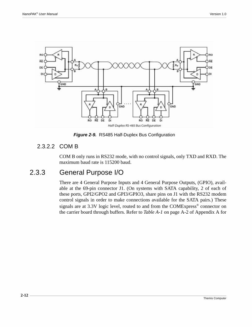
2.3.2.2 COM B
COM B only runs in RS232 mode, with no control signals, only TXD and RXD. Themaximum baud rate is 115200 baud.
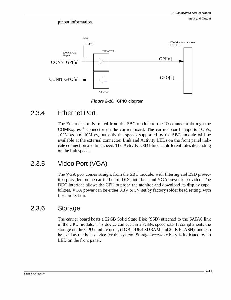
2.3.3 General Purpose I/OThere are 4 General Purpose Inputs and 4 General Purpose Outputs, (GPIO), avail-able at the 69-pin connector J1. (On systems with SATA capability, 2 of each ofthese ports, GPI2/GPO2 and GPI3/GPIO3, share pins on J1 with the RS232 modemcontrol signals in order to make connections available for the SATA pairs.) Thesesignals are at 3.3V logic level, routed to and from the COMExpress® connector onthe carrier board through buffers. Refer to Table A-1 on page A-2 of Appendix A for
Figure 2-9. RS485 Half-Duplex Bus Configuration
2—Installation and Operation
Input and Output
2-13Themis Computer
pinout information.
2.3.4 Ethernet Port
The Ethernet port is routed from the SBC module to the IO connector through theCOMExpress® connector on the carrier board. The carrier board supports 1Gb/s,100Mb/s and 10Mb/s, but only the speeds supported by the SBC module will beavailable at the external connector. Link and Activity LEDs on the front panel indi-cate connection and link speed. The Activity LED blinks at different rates dependingon the link speed.
2.3.5 Video Port (VGA)
The VGA port comes straight from the SBC module, with filtering and ESD protec-tion provided on the carrier board. DDC interface and VGA power is provided. TheDDC interface allows the CPU to probe the monitor and download its display capa-bilities. VGA power can be either 3.3V or 5V, set by factory solder bead setting, withfuse protection.
2.3.6 Storage
The carrier board hosts a 32GB Solid State Disk (SSD) attached to the SATA0 linkof the CPU module. This device can sustain a 3GB/s speed rate. It complements thestorage on the CPU module itself, (1GB DDR3 SDRAM and 2GB FLASH), and canbe used as the boot device for the system. Storage access activity is indicated by anLED on the front panel.
Figure 2-10. GPIO diagram
74LVC125
3.3V
IO connector
COM-Express connector
69-pin
220 pin
CONN_GPI[n]GPI[n]
4.7K
CONN_GPO[n] GPO[n]
74LVC08

2-14Themis Computer
NanoPAK® User Manual Version 1.0
2.3.7 HD Audio Interface
The HD Audio interface is under the control of the ALC889 codec that communi-cates with the CPU through the AC97/HDA link available on the COMExpress®
Type 1 interface. Only a subset of the codec is used, Line1/Mic1 In, and Line1 Out.Selection between Line In and Mic In is done by solder bead setting, which setting isreadable by software. Table 2-6 lists these solder bead settings.
See Table A-5, "Solder Bead Settings," on page A-11 of Appendix A for furtherdetails.
Table 2-6. MIC/LINE Audio Settings
Solder BeadsSetting
MIC 1 Line1
SB14 1-2 2-3
SB15 1-2 2-3
SB12 1-2 2-3
SB20 1-2 2-3
2-15Themis Computer
2—Installation and Operation
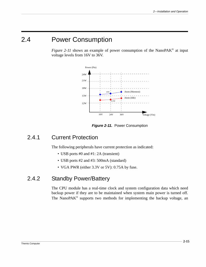
2.4 Power Consumption
Figure 2-11 shows an example of power consumption of the NanoPAK® at inputvoltage levels from 16V to 36V.
2.4.1 Current Protection
The following peripherals have current protection as indicated:
• USB ports #0 and #1: 2A (transient)
• USB ports #2 and #3: 500mA (standard)
• VGA PWR (either 3.3V or 5V): 0.75A by fuse.
2.4.2 Standby Power/Battery
The CPU module has a real-time clock and system configuration data which needbackup power if they are to be maintained when system main power is turned off.The NanoPAK® supports two methods for implementing the backup voltage, an
Figure 2-11. Power Consumption
12W
15W
18W
21W
24W
Power (Pin)
Voltage (Vin)16V 24V 36V
Atom (Idle)
Atom (Memtest)
13.5W
16W
2-16Themis Computer
NanoPAK® User Manual Version 1.0
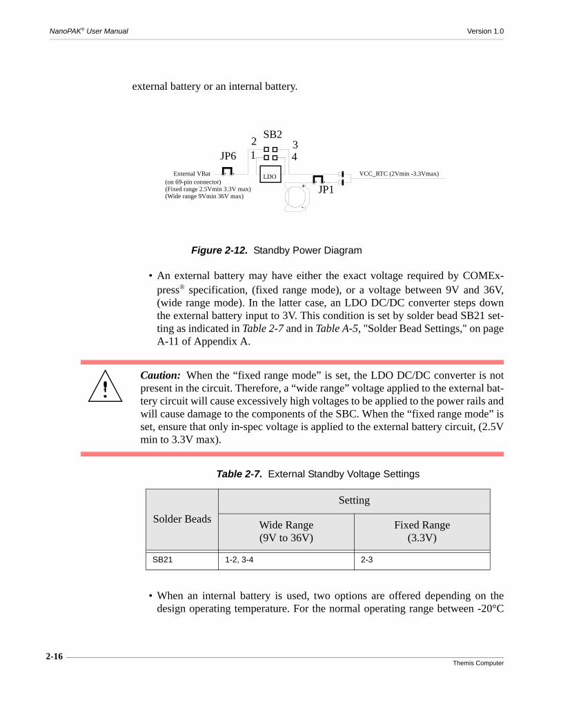
external battery or an internal battery.
• An external battery may have either the exact voltage required by COMEx-press® specification, (fixed range mode), or a voltage between 9V and 36V,(wide range mode). In the latter case, an LDO DC/DC converter steps downthe external battery input to 3V. This condition is set by solder bead SB21 set-ting as indicated in Table 2-7 and in Table A-5, "Solder Bead Settings," on pageA-11 of Appendix A.
• When an internal battery is used, two options are offered depending on thedesign operating temperature. For the normal operating range between -20°C
Figure 2-12. Standby Power Diagram
VCC_RTC (2Vmin -3.3Vmax)
+
-
LDO(on 69-pin connector)
External VBat
(Fixed range 2.5Vmin 3.3V max)(Wide range 9Vmin 36V max)
SB2
1 4
2 3
JP1
JP6
Caution: When the “fixed range mode” is set, the LDO DC/DC converter is notpresent in the circuit. Therefore, a “wide range” voltage applied to the external bat-tery circuit will cause excessively high voltages to be applied to the power rails andwill cause damage to the components of the SBC. When the “fixed range mode” isset, ensure that only in-spec voltage is applied to the external battery circuit, (2.5Vmin to 3.3V max).
Table 2-7. External Standby Voltage Settings
Solder Beads
Setting
Wide Range(9V to 36V)
Fixed Range(3.3V)
SB21 1-2, 3-4 2-3

2-17Themis Computer
2—Installation and Operation
Power Consumption
and 80°C, a removable battery BR1225 can be used. The removable batterycan be accessed for replacement by removing the front bezel. The removablebattery holder is located on the bottom of the LED/battery board. (Refer to Fig-ure 2-14 on page 2-18 for battery replacement). For an extended temperaturerange, the soldered type BR1225A battery is mandatory, and is not fieldreplaceable.
• Jumper JP1 allows the user to disconnect the local battery from the load. JP1 islocated on the bottom of the LED/battery board, which is the top board of the
Figure 2-13. Jumper Locations
NanoPAK
JP1 Location JP6 Location
Bat
tery

NanoPAK® User Manual Version 1.0
2-18Themis Computer
stack, at the forward left edge. Access to this jumper is possible by removingthe front bezel. (Refer to Figure 2-13 for location).
• Jumper JP6 is available to completely disconnect the external power sourcefrom the standby power circuit. JP6 is located on the top of the SBC carrierboard, which is the bottom board of the stack, at the forward right edge. Accessto this jumper is possible by removing the front bezel. (Refer to Figure 2-13for location).
2.4.3 Backup Battery Replacement
Refer to Figure 2-14, and the steps following, (next page), for battery replacement.The replacement battery type is BR1225. Tools required are a 3.5mm socket driver,no. 1 Phillips screwdriver, and a .050in, (H1.3 European), hex wrench for the I/Ocable connector.
Figure 2-14. Backup Battery Replacement
+
-
BatteryTwo Jack Screws

2-19Themis Computer
2—Installation and Operation
Power Consumption
1. If the I/O cable is connected, remove it using the .050in, (H1.3 European), hexwrench.
2. Remove two Phillips head screws on each side of the front of the module.
3. Remove the two jack screws at the connector with the 3.5mm socket driver.
4. Remove the front panel.
5. Remove the old battery from the battery holder. It may be necessary to usetweezers or a needle nose pliers in order to grip the old battery. Note that if thetool does not have insulated surfaces, you will short the battery unless yougrip only the rim of the battery.
6. Install the replacement battery, plus side down, by sliding it into the batteryholder.
7. Replace the front panel. Insert and tighten the two jack screws into the con-nector holes.
8. Replace and tighten the two Phillips head screws in the sides.
9. Reinstall the I/O cable if desired, using the .050in, (H1.3 European), hexwrench. Caution! Insure that power is removed from the power contacts toavoid possible damage to the system. Apply power only after the connector issecured in place.

2-20Themis Computer
NanoPAK® User Manual Version 1.0
3-1Themis Computer
3
InsydeH2O® BIOS Setup Utility
3.1 Introduction
This chapter describes the InsydeH2O® BIOS Setup Utility for the NanoPAK® Sin-gle Board Computer. The InsydeH2O® ROM BIOS is an UEFI-type BIOS stored ina Flash EEPROM which is connected through SPI. This allows the BIOS configura-tion data to be retained when power is removed, and allows the BIOS to be easilyupdated. However, the system date and time is not retained when power is removed.
Caution: Do not upgrade the BIOS unless your system has a BIOS-related issue.Flashing the wrong BIOS can cause irreparable damage to the system. In no eventshall Themis be liable for direct, indirect, special, incidental, or consequential dam-ages arising from a BIOS update. If you have to update the BIOS, do not shut downor reset the system while the BIOS is updating. This is to avoid possible boot fail-ure.
BIOS SetupUtility Chapter

NanoPAK® User Manual Version 1.0
3-2Themis Computer
3.2 Starting the BIOS Setup UtilityThe BIOS Setup Utility may be access while the system is booting up after initialpower application, or when rebooted by simultaneously pressing the <CTRL>,<ALT> and <DELETE> keys. An initial “splash” screen will appear, and while the“splash” screen is visible, pressing the <F2> key will bring up the BIOS Setup Util-ity (See Figure 3-1 on page 3-2). It may be necessary to press the <F2> key morethan once to bring up the Setup screen. The first screen to appear is the BIOS Infor-mation Screen (Figure 3-2) which displays the BIOS version details. Use the left-right <arrow> keys to select the desired menu.
Figure 3-1. Splash Screen
Figure 3-2. BIOS Information Screen
3-3Themis Computer
3—InsydeH2O® BIOS Setup Utility
Starting the BIOS Setup Utility
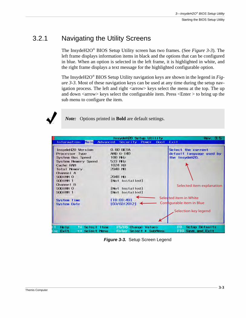
3.2.1 Navigating the Utility Screens
The InsydeH2O® BIOS Setup Utility screen has two frames. (See Figure 3-3). Theleft frame displays information items in black and the options that can be configuredin blue. When an option is selected in the left frame, it is highlighted in white, andthe right frame displays a text message for the highlighted configurable option.
The InsydeH2O® BIOS Setup Utility navigation keys are shown in the legend in Fig-ure 3-3. Most of these navigation keys can be used at any time during the setup nav-igation process. The left and right <arrow> keys select the menu at the top. The upand down <arrow> keys select the configurable item. Press <Enter > to bring up thesub menu to configure the item.
Note: Options printed in Bold are default settings.
Figure 3-3. Setup Screen Legend
Selected item in White
Configurable item in Blue
Selected item explanation
Selection key legend
3-4Themis Computer
NanoPAK® User Manual Version 1.0
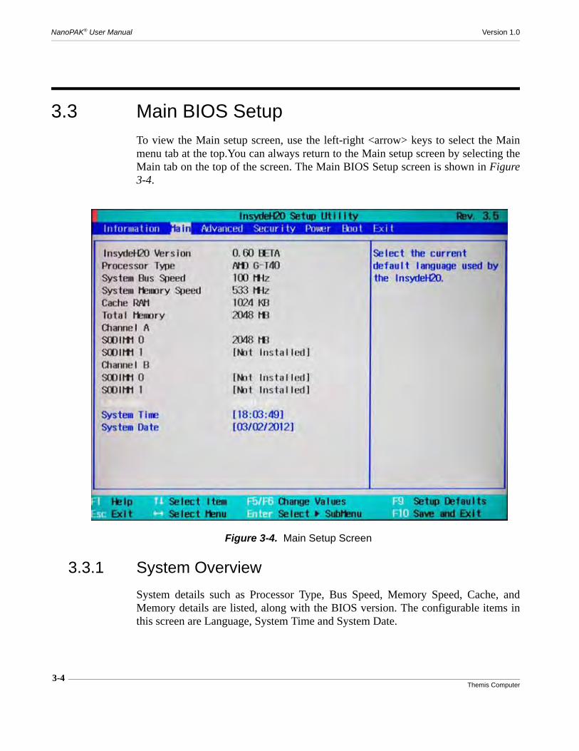
3.3 Main BIOS SetupTo view the Main setup screen, use the left-right <arrow> keys to select the Mainmenu tab at the top.You can always return to the Main setup screen by selecting theMain tab on the top of the screen. The Main BIOS Setup screen is shown in Figure3-4.
3.3.1 System Overview
System details such as Processor Type, Bus Speed, Memory Speed, Cache, andMemory details are listed, along with the BIOS version. The configurable items inthis screen are Language, System Time and System Date.
Figure 3-4. Main Setup Screen
3-5Themis Computer
3—InsydeH2O® BIOS Setup Utility
Main BIOS Setup
3.3.2 System Time/System DateUse this option to change the system time and date. Highlight System Date or SystemTime using the <Arrow> keys. Key in new values through the keyboard and press<Enter>. Press the <Tab> key to move between fields. The date must be entered inMM/DD/YY format. The time is entered in HH:MM:SS format.
3.3.3 LanguageUse the <Arrow> keys to select the desired BIOS Menu language, and press <Enter>to select it.
Note: The time is in the 24-hour format. For example, 5:30 P.M. appears as17:30:00.

3-6Themis Computer
NanoPAK® User Manual Version 1.0
3.4 Advanced Setup
Use the horizontal arrow keys to select the Advanced Settings screen. Use the verti-cal arrows to select the submenu items, and hit <Enter> to access them.
Caution: It is advisable not to change from the default settings, as they are set ac-cording to the hardware design of this board. Options in Bold are the default set-tings.
Figure 3-5. Advanced Settings Screen

3-7Themis Computer
3—InsydeH2O® BIOS Setup Utility
Advanced Setup
3.4.1 Boot Configuration
• The Boot Configuration screen sets the power-on state for the Numlock key.
Figure 3-6. Boot Configuration Settings

3-8Themis Computer
NanoPAK® User Manual Version 1.0
3.4.2 Peripherals Configuration
• Enhanced Host Controller Interface (EHCI)Sets the EHCI for USB ports 0, 1, and 2 to Auto detect or Disabled.
• Azalia
• SATA
• SATA Port(s) Power on
• Serial Port(s)
Figure 3-7. Peripheral Configuration Settings
3-9Themis Computer
3—InsydeH2O® BIOS Setup Utility
Advanced Setup
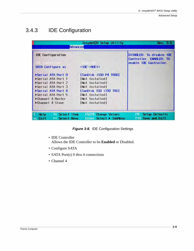
3.4.3 IDE Configuration
• IDE ControllerAllows the IDE Controller to be Enabled or Disabled.
• Configure SATA
• SATA Port(s) 0 thru 4 connections
• Channel 4
Figure 3-8. IDE Configuration Settings
3-10Themis Computer
NanoPAK® User Manual Version 1.0
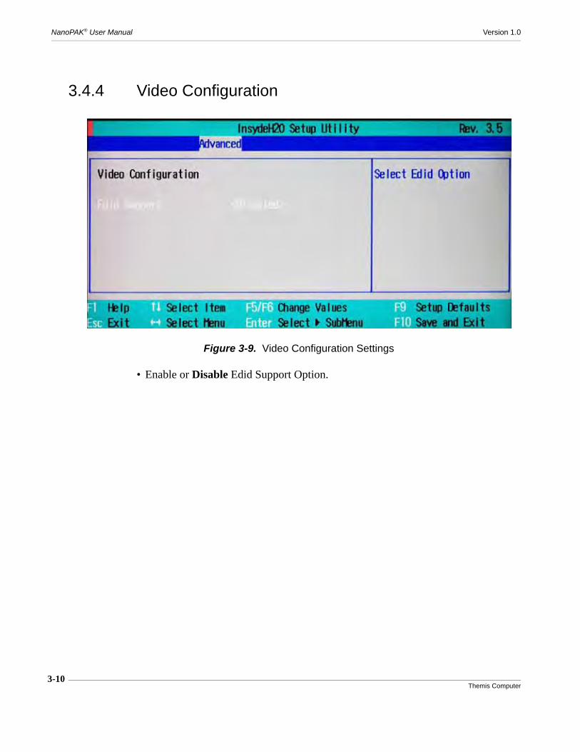
3.4.4 Video Configuration
• Enable or Disable Edid Support Option.
Figure 3-9. Video Configuration Settings

3-11Themis Computer
3—InsydeH2O® BIOS Setup Utility
Advanced Setup
3.4.5 USB Configuration
• Enable or Disable USB 2.0 Controller.
• Enable or Disable USB Legacy support.
Figure 3-10. USB Configuration Settings

3-12Themis Computer
NanoPAK® User Manual Version 1.0
3.4.6 Chipset Configuration
• Select NorthBridge/GNB Options Screen.
• Select Hudson-1 FCH Family Product Errata Screen.
• Select SouthBridge/GPP Options Screen.
• Set the PCI Latency Timer Setting
• Enable or Disable Spread Spectrum Operation.
Figure 3-11. Chipset Configuration Settings
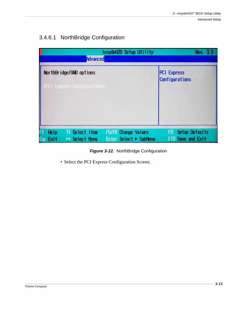
3-13Themis Computer
3—InsydeH2O® BIOS Setup Utility
Advanced Setup
3.4.6.1 NorthBridge Configuration
• Select the PCI Express Configuration Screen.
Figure 3-12. NorthBridge Configuration
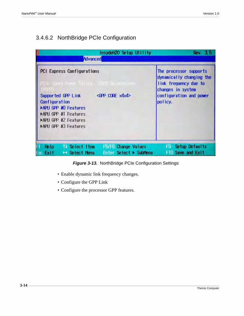
3-14Themis Computer
NanoPAK® User Manual Version 1.0
3.4.6.2 NorthBridge PCIe Configuration
• Enable dynamic link frequency changes.
• Configure the GPP Link
• Configure the processor GPP features.
Figure 3-13. NorthBridge PCIe Configuration Settings
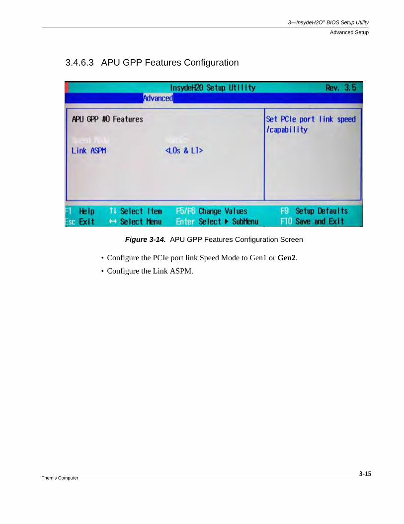
3-15Themis Computer
3—InsydeH2O® BIOS Setup Utility
Advanced Setup
3.4.6.3 APU GPP Features Configuration
• Configure the PCIe port link Speed Mode to Gen1 or Gen2.
• Configure the Link ASPM.
Figure 3-14. APU GPP Features Configuration Screen

3-16Themis Computer
NanoPAK® User Manual Version 1.0
3.4.6.4 Hudson-1 FCH Configuration
• Enable or Disable various FCH fixes.
Figure 3-15. Hudson-1 FCH Configuration Settings
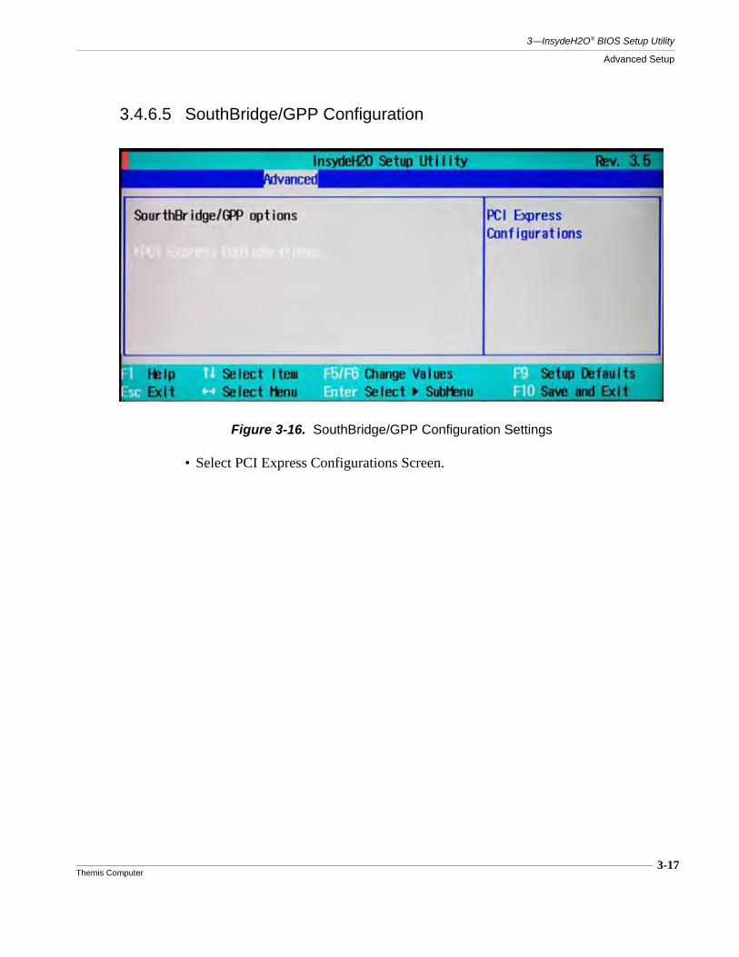
3-17Themis Computer
3—InsydeH2O® BIOS Setup Utility
Advanced Setup
3.4.6.5 SouthBridge/GPP Configuration
• Select PCI Express Configurations Screen.
Figure 3-16. SouthBridge/GPP Configuration Settings
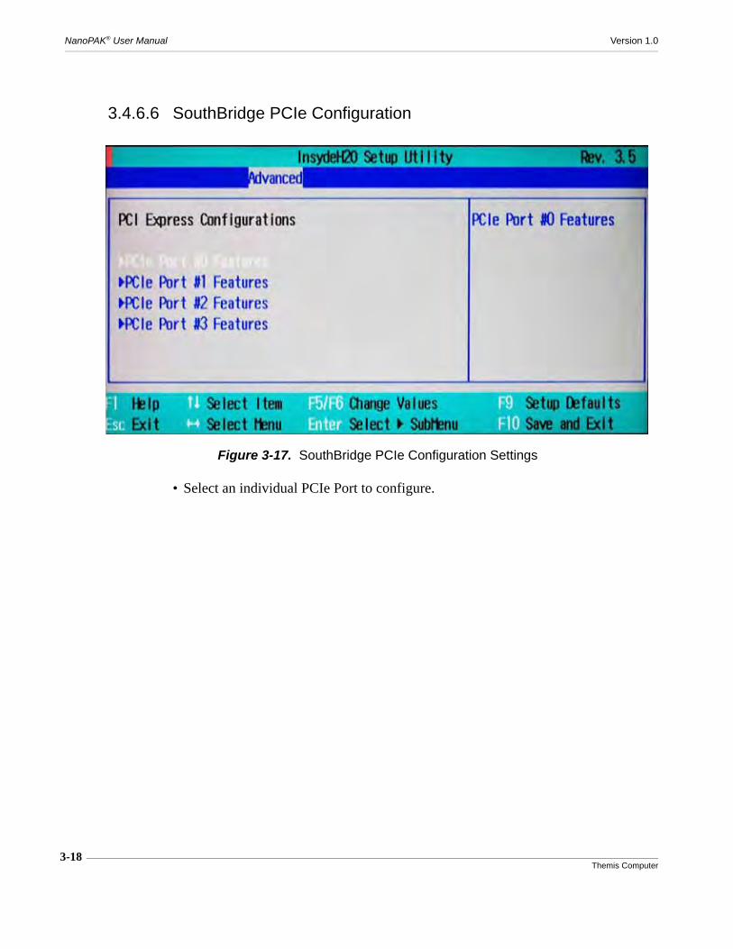
3-18Themis Computer
NanoPAK® User Manual Version 1.0
3.4.6.6 SouthBridge PCIe Configuration
• Select an individual PCIe Port to configure.
Figure 3-17. SouthBridge PCIe Configuration Settings
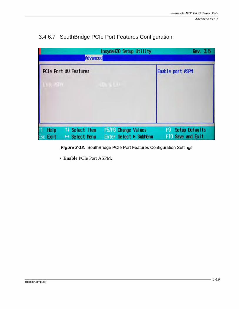
3-19Themis Computer
3—InsydeH2O® BIOS Setup Utility
Advanced Setup
3.4.6.7 SouthBridge PCIe Port Features Configuration
• Enable PCIe Port ASPM.
Figure 3-18. SouthBridge PCIe Port Features Configuration Settings

NanoPAK® User Manual Version 1.0
3-20Themis Computer
3.4.7 ACPI Tables/Features Control
• FACP - C2 Latency Value = Enabled
•
• FACP - C3 Latency Value = Enabled
•
• FACP - RTC s4 Wakeup = Enabled
•
• APIC - IO APIC Mode = Enabled
• HPET - HPET Support = Enabled
• _OCS Support = Enabled
• Fusion Utility = Disabled
Figure 3-19. ACPI Tables/Features Control
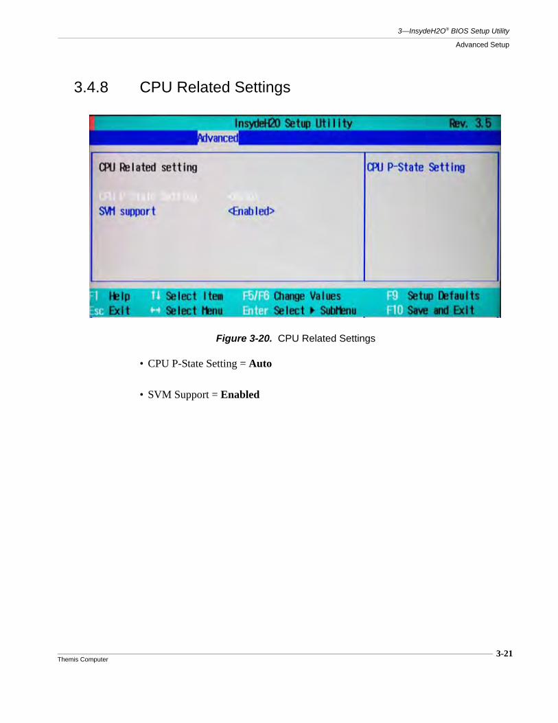
3-21Themis Computer
3—InsydeH2O® BIOS Setup Utility
Advanced Setup
3.4.8 CPU Related Settings
• CPU P-State Setting = Auto
• SVM Support = Enabled
Figure 3-20. CPU Related Settings
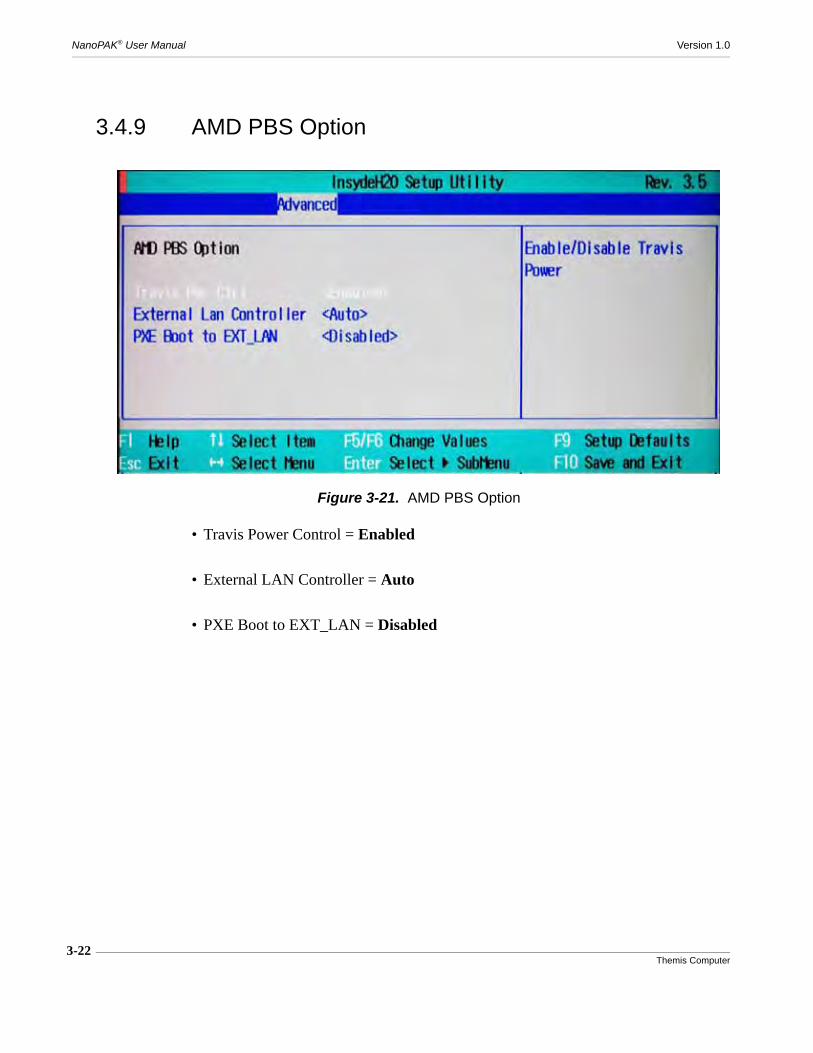
3-22Themis Computer
NanoPAK® User Manual Version 1.0
3.4.9 AMD PBS Option
• Travis Power Control = Enabled
• External LAN Controller = Auto
• PXE Boot to EXT_LAN = Disabled
Figure 3-21. AMD PBS Option
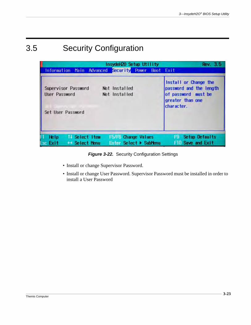
3-23Themis Computer
3—InsydeH2O® BIOS Setup Utility
3.5 Security Configuration
• Install or change Supervisor Password.
• Install or change User Password. Supervisor Password must be installed in order to install a User Password
Figure 3-22. Security Configuration Settings

3-24Themis Computer
NanoPAK® User Manual Version 1.0
3.6 Power Configuration
• Select the Advanced CPU Control screen to configure various CPU parameters.
• ACPI s3 = Enabled
• Thermal Fan Control = Auto
• Wake on PME = Enabled
• Auto Wake on s5 = Disabled
Figure 3-23. Power Configuration

3-25Themis Computer
3—InsydeH2O® BIOS Setup Utility
Power Configuration
3.6.1 Advanced CPU Control
• Cool N’ Quiet Support = EnabledEnable or Disable Cool and Quiet Support.
• Hardware Thermal Control = Auto
Figure 3-24. Advanced CPU Control
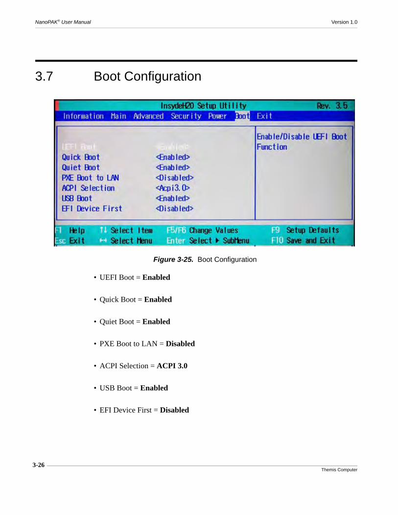
3-26Themis Computer
NanoPAK® User Manual Version 1.0
3.7 Boot Configuration
• UEFI Boot = Enabled
• Quick Boot = Enabled
• Quiet Boot = Enabled
• PXE Boot to LAN = Disabled
• ACPI Selection = ACPI 3.0
• USB Boot = Enabled
• EFI Device First = Disabled
Figure 3-25. Boot Configuration
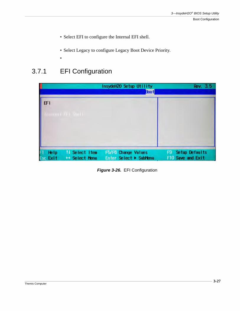
3-27Themis Computer
3—InsydeH2O® BIOS Setup Utility
Boot Configuration
• Select EFI to configure the Internal EFI shell.
• Select Legacy to configure Legacy Boot Device Priority.
•
3.7.1 EFI Configuration
Figure 3-26. EFI Configuration
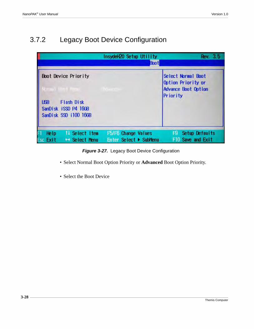
3-28Themis Computer
NanoPAK® User Manual Version 1.0
3.7.2 Legacy Boot Device Configuration
• Select Normal Boot Option Priority or Advanced Boot Option Priority.
• Select the Boot Device
Figure 3-27. Legacy Boot Device Configuration

3-29Themis Computer
3—InsydeH2O® BIOS Setup Utility
3.8 Exit Menu
• Exit Saving ChangesWhen users have completed system configuration, select this option to save changes, exit BIOS setup menu and reboot the computer to take effect of all sys-tem configuration parameters.
• Save Change Without ExitSave changes and continue in the BIOS Setup Utility.
• Exit Discarding ChangesSelect this option to quit Setup without making any permanent changes to the sys-tem configuration.
• Load Optimal DefaultsThe BIOS automatically configures all setup items to optimal settings when users select this option. Optimal Defaults are designed for maximum system perfor-mance, but may not work best for all computer applications. In particular, do not use the Optimal Defaults if the user’s computer is experiencing system configura-tion problems.
• Load Custom DefaultsLoad previously saved Custom Defaults.
Figure 3-28. Exit Menu

3-30Themis Computer
NanoPAK® User Manual Version 1.0
• Save Custom DefaultsSave the current settings as Custom Defaults.
• Discard ChangesDiscard any changes previously made and continue in the BIOS Setup Utility.

4-1Themis Computer
4
AMI BIOS Setup Utility
4.1 Introduction
This chapter describes the AMI BIOS Setup Utility for the NanoPAK® Single BoardComputer. The AMI ROM BIOS is stored in a Flash EEPROM and can be easilyupdated. This chapter explains the basic navigation of the AMI BIOS Setup Utilitysetup screens.
4.1.1 Starting the BIOS Setup Utility
Turn on the computer and check for the “patch code”. If there is a number assignedto the patch code, the on board CPU is supported by current BIOS. If there is nonumber assigned to the patch code, please contact a Themis application engineer toobtain an up-to-date patch code file, to ensure the system status of CPU is valid.Then press <DEL> to enter Setup menu.
Caution: Do not upgrade the BIOS unless your system has a BIOS-related issue.Flashing the wrong BIOS can cause irreparable damage to the system. In no eventshall Themis be liable for direct, indirect, special, incidental, or consequential dam-ages arising from a BIOS update. If you have to update the BIOS, do not shut downor reset the system while the BIOS is updating. This is to avoid possible boot fail-ure.
4
BIOS SetupUtility
Chapter

4-2Themis Computer
NanoPAK® User Manual Version 1.0
The first screen to appear is the Main Settings Screen. (See Figure 4-1). The MainBIOS setup menu screen has three frames. The left frame displays all the optionsthat can be configured. Grayed-out options cannot be configured. Options in bluecan be configured by the user. The bottom right frame displays the key legend. Theframe above the key legend is an area reserved for a text message. When an option isselected in the left frame, it is highlighted in white. Often a text message will accom-pany it.
The AMI BIOS Setup Utility uses a key-based navigation system called “hot keys”.Most of the AMI BIOS setup utility “hot keys” can be used at any time during thesetup navigation process. These keys include <F1>, <F10>, <Enter>, <ESC>, arrowkeys, etc.
Note: Options printed in Bold are default settings.
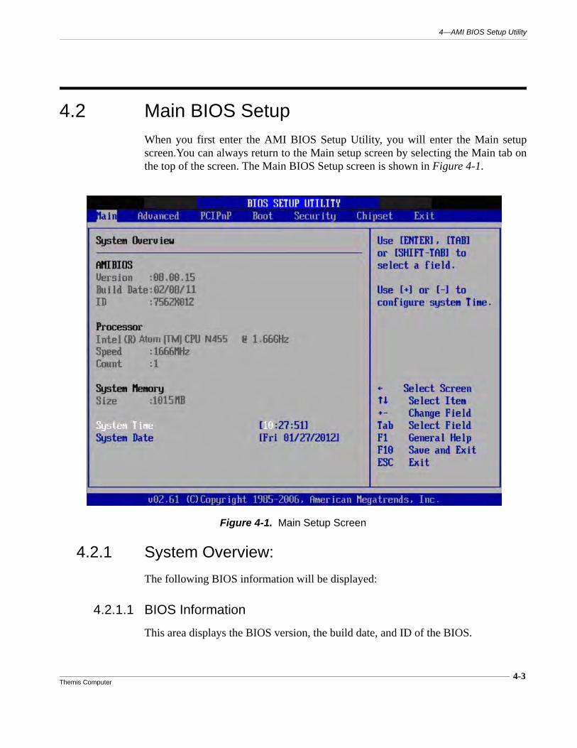
4-3Themis Computer
4—AMI BIOS Setup Utility
4.2 Main BIOS SetupWhen you first enter the AMI BIOS Setup Utility, you will enter the Main setupscreen.You can always return to the Main setup screen by selecting the Main tab onthe top of the screen. The Main BIOS Setup screen is shown in Figure 4-1.
4.2.1 System Overview:
The following BIOS information will be displayed:
4.2.1.1 BIOS Information
This area displays the BIOS version, the build date, and ID of the BIOS.
Figure 4-1. Main Setup Screen

4-4Themis Computer
NanoPAK® User Manual Version 1.0
4.2.1.2 System Memory Information
This area displays the size of the system memory.
4.2.1.3 System Time/System Date
Use this option to change the system time and date. Highlight System Date or SystemTime using the <Arrow> keys. Key in new values through the keyboard and press<Enter>. Press the <Tab> key to move between fields. The date must be entered inMM/DD/YY format. The time is entered in HH:MM:SS format.
Note: The time is in the 24-hour format. For example, 5:30 P.M. appears as17:30:00.
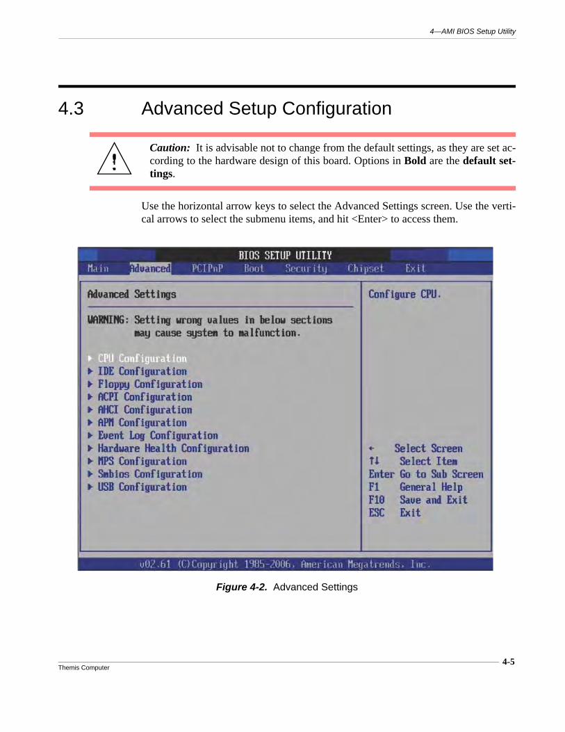
4-5Themis Computer
4—AMI BIOS Setup Utility
4.3 Advanced Setup Configuration
Use the horizontal arrow keys to select the Advanced Settings screen. Use the verti-cal arrows to select the submenu items, and hit <Enter> to access them.
Caution: It is advisable not to change from the default settings, as they are set ac-cording to the hardware design of this board. Options in Bold are the default set-tings.
Figure 4-2. Advanced Settings
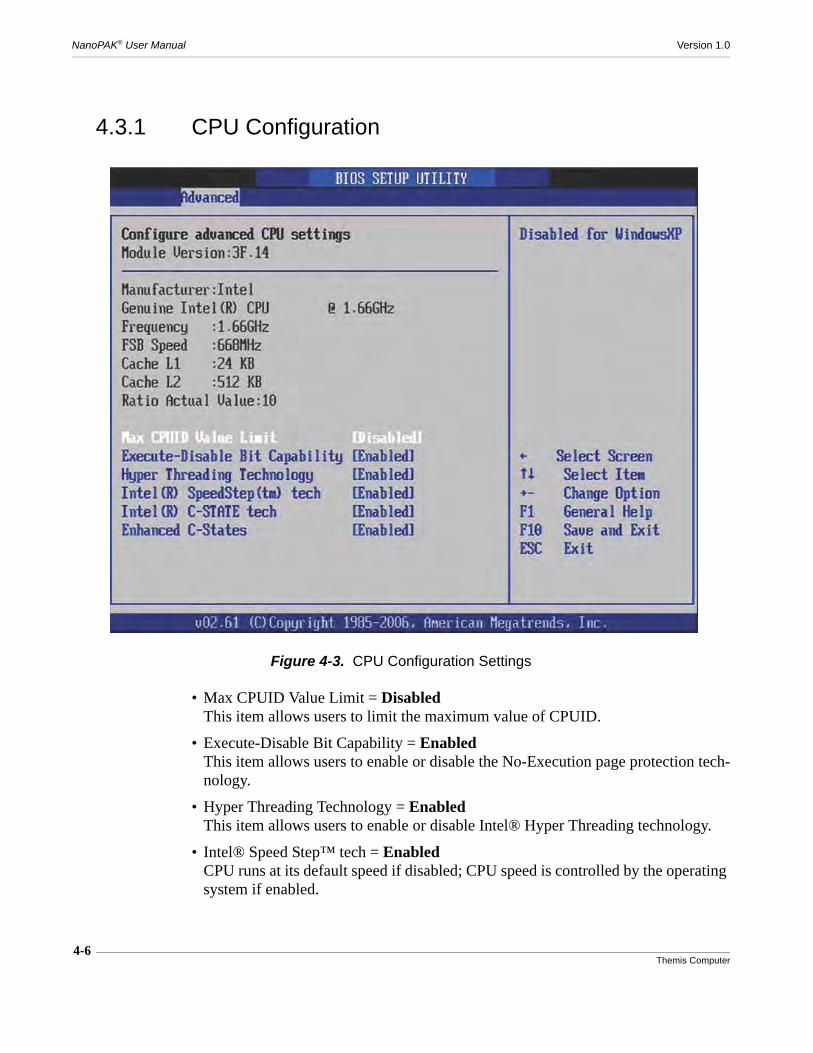
4-6Themis Computer
NanoPAK® User Manual Version 1.0
4.3.1 CPU Configuration
• Max CPUID Value Limit = DisabledThis item allows users to limit the maximum value of CPUID.
• Execute-Disable Bit Capability = EnabledThis item allows users to enable or disable the No-Execution page protection tech-nology.
• Hyper Threading Technology = EnabledThis item allows users to enable or disable Intel® Hyper Threading technology.
• Intel® Speed Step™ tech = EnabledCPU runs at its default speed if disabled; CPU speed is controlled by the operating system if enabled.
Figure 4-3. CPU Configuration Settings

4-7Themis Computer
4—AMI BIOS Setup Utility
Advanced Setup Configuration
• Intel® C-STATE tech = EnabledThis item allows the CPU to save more power in idle mode.
• Enhanced C-States = EnabledEnable / Disable Intel® C-STATE technology
4.3.2 IDE Configuration
• ATA/IDE Configuration = EnhancedThis item allows users to select Disabled / Compatible / Enhanced modes.When set to Enhanced mode, users can select IDE or AHCI mode. When set to Compatible mode, users can select “SATA only,” “SATA Primary, PATA Second-ary” or “PATA Only.”
Figure 4-4. IDE Configuration Settings
4-8Themis Computer
NanoPAK® User Manual Version 1.0
• Primary / Secondary / Third IDE Master / SlaveBIOS auto detects the presence of an IDE device, and displays the status of auto detection of the IDE device.
— Type: Select the type of SATA driver; [Not Installed] [Auto] [CD/DVD][ARMD]
— LBA/Large Mode: Enables or Disables the LBA Mode.
— Block (Multi-Sector Transfer): Enables or Disables data multi-sectorstransfers.
— PIO Mode: Select the operating mode of PIO.
— DMA Mode: Select the operating mode of DMA
— S.M.A.R.T.: Select the smart monitoring, analysis, and reportingtechnology.
— 32Bit Data Transfer: Enables or disables 32-bit data transfer.
• Hard Disk Write Protect = DisabledDisable / Enable device write protection. This will be effective only if device is accessed through BIOS.
• IDE Detect Time Out (Sec)This item allows users to select the time out value for detecting ATA/ATAPI devices.
• ATA(PI) 80Pin Cable DetectionThis item allows users to select the way to detect IDE 80-pin cable.
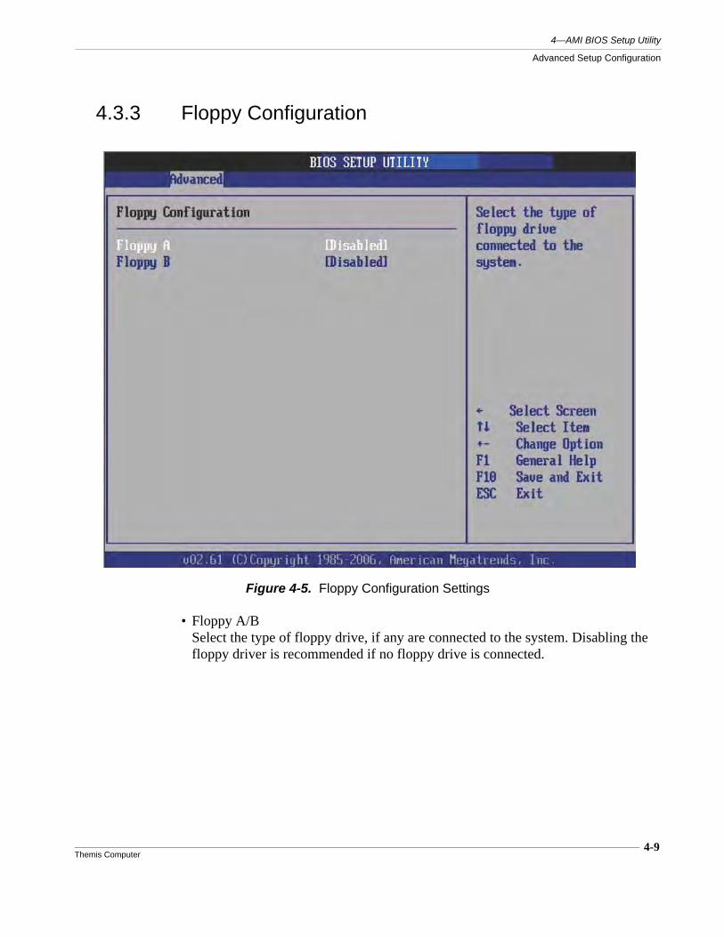
4-9Themis Computer
4—AMI BIOS Setup Utility
Advanced Setup Configuration
4.3.3 Floppy Configuration
• Floppy A/BSelect the type of floppy drive, if any are connected to the system. Disabling the floppy driver is recommended if no floppy drive is connected.
Figure 4-5. Floppy Configuration Settings

4-10Themis Computer
NanoPAK® User Manual Version 1.0
4.3.4 ACPI Settings
Figure 4-6. ACPI Settings
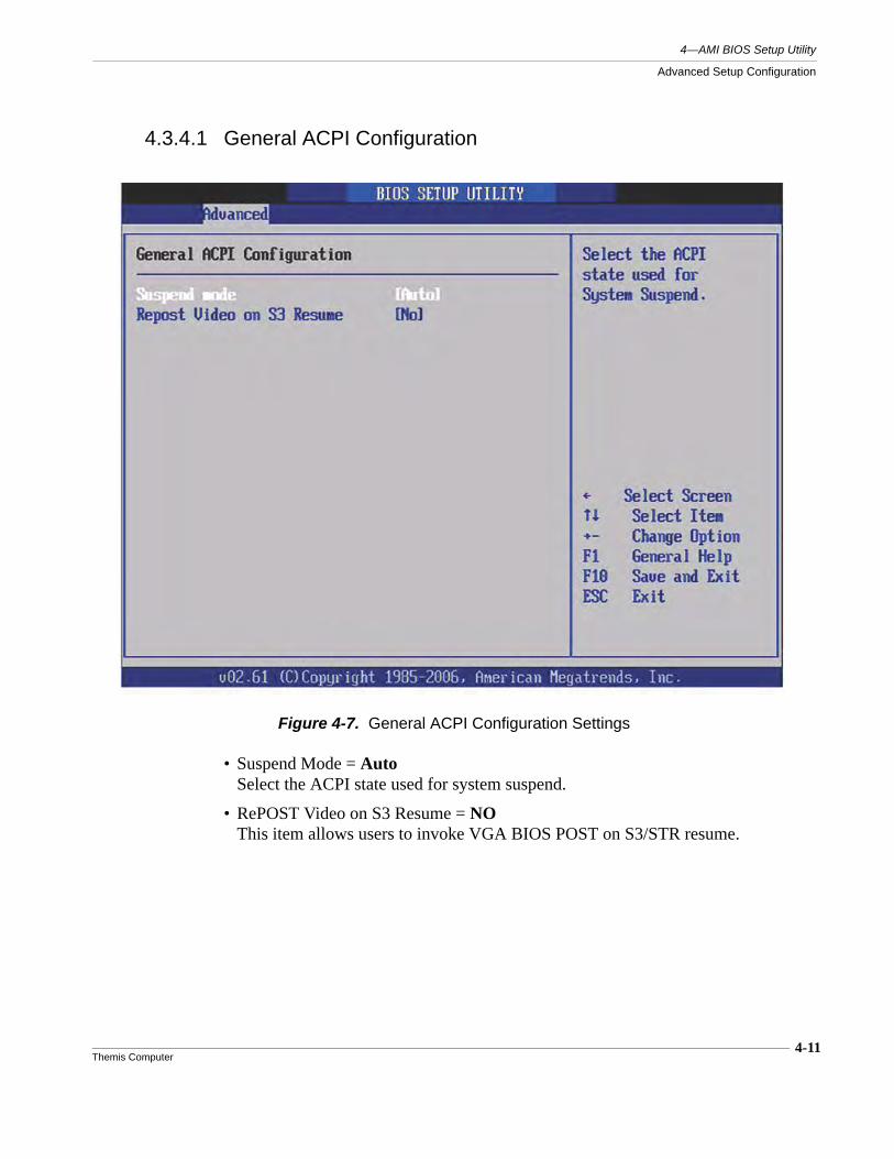
4-11Themis Computer
4—AMI BIOS Setup Utility
Advanced Setup Configuration
4.3.4.1 General ACPI Configuration
• Suspend Mode = AutoSelect the ACPI state used for system suspend.
• RePOST Video on S3 Resume = NOThis item allows users to invoke VGA BIOS POST on S3/STR resume.
Figure 4-7. General ACPI Configuration Settings
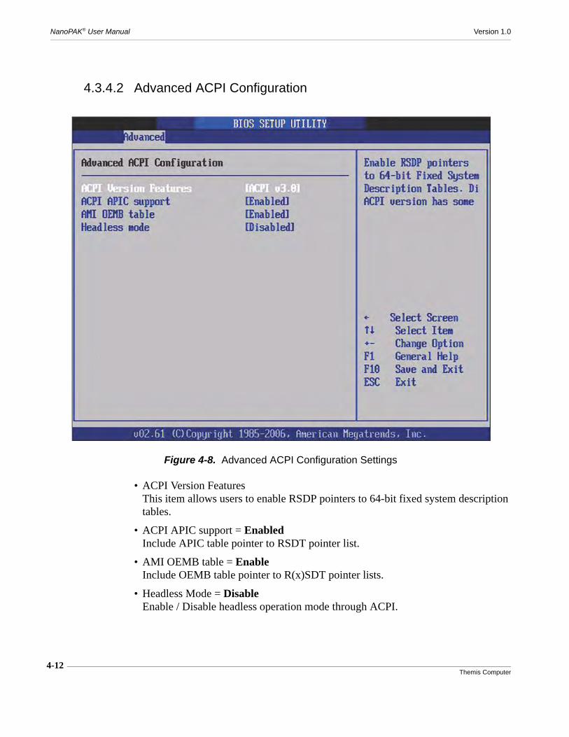
4-12Themis Computer
NanoPAK® User Manual Version 1.0
4.3.4.2 Advanced ACPI Configuration
• ACPI Version FeaturesThis item allows users to enable RSDP pointers to 64-bit fixed system description tables.
• ACPI APIC support = EnabledInclude APIC table pointer to RSDT pointer list.
• AMI OEMB table = EnableInclude OEMB table pointer to R(x)SDT pointer lists.
• Headless Mode = DisableEnable / Disable headless operation mode through ACPI.
Figure 4-8. Advanced ACPI Configuration Settings

4-13Themis Computer
4—AMI BIOS Setup Utility
Advanced Setup Configuration
4.3.4.3 Chipset ACPI Configuration
• Energy Lake Feature = DisabledThis item allows users to configure Intel’s® Energy Lake power management technology.
• APIC ACPI SCI IRQ = DisabledEnable / Disable APIC ACPI SCI IRQ
• USB Device Wakeup From S3/S4 = DisabledEnable / Disable USB Device Wakeup from S3/S4
• High Performance Event Timer = DisabledEnable / Disable High Performance event timer.
Figure 4-9. Chipset ACPI Configuration Settings
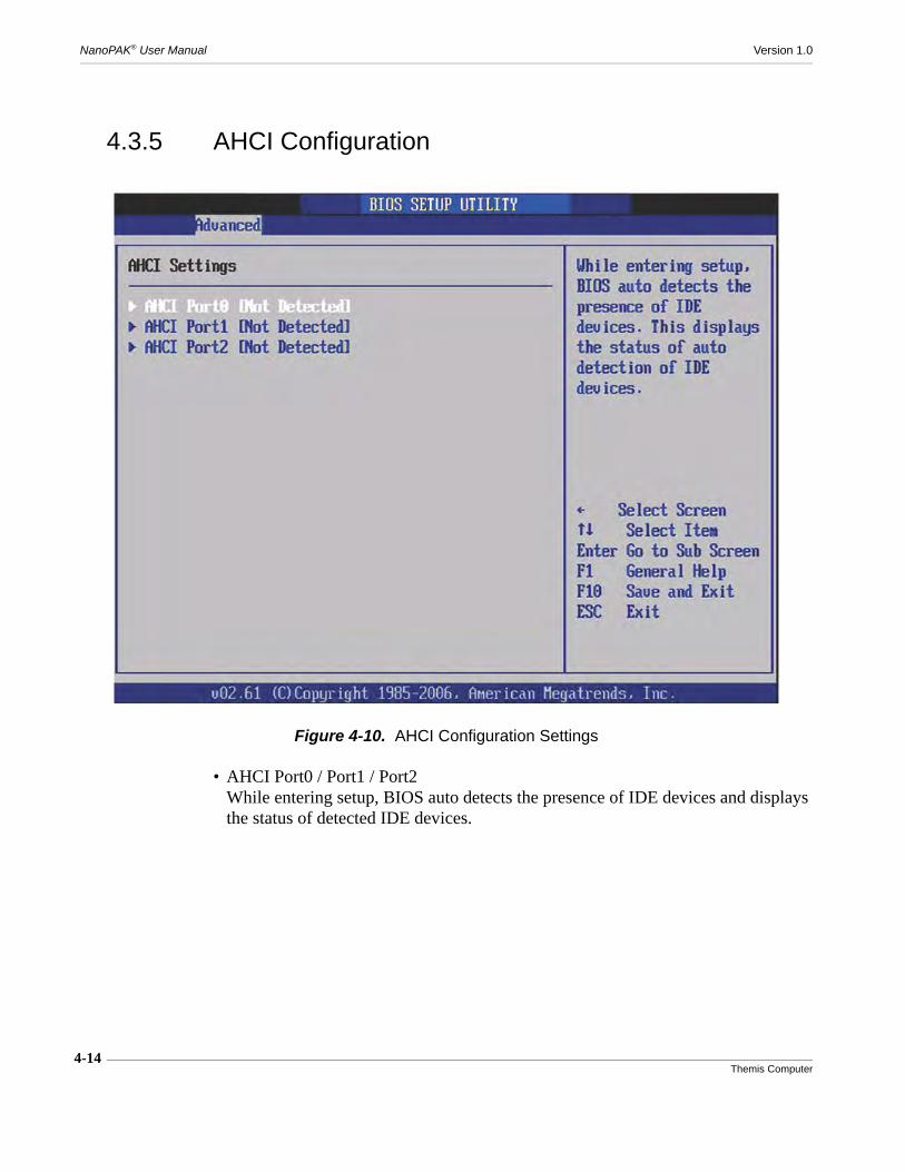
4-14Themis Computer
NanoPAK® User Manual Version 1.0
4.3.5 AHCI Configuration
• AHCI Port0 / Port1 / Port2While entering setup, BIOS auto detects the presence of IDE devices and displays the status of detected IDE devices.
Figure 4-10. AHCI Configuration Settings

4-15Themis Computer
4—AMI BIOS Setup Utility
Advanced Setup Configuration
4.3.6 Event Log Configuration
• View Event LogView all unread events in the Event Log.
• Mark all events as readMark all unread events as read.
• Clear Event LogDiscard all events in the Event Log.
Figure 4-11. Event Log Configuration Settings
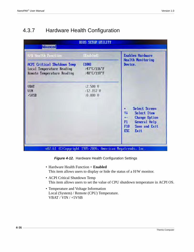
4-16Themis Computer
NanoPAK® User Manual Version 1.0
4.3.7 Hardware Health Configuration
• Hardware Health Function = EnabledThis item allows users to display or hide the status of a H/W monitor.
• ACPI Critical Shutdown TempThis item allows users to set the value of CPU shutdown temperature in ACPI OS.
• Temperature and Voltage InformationLocal (System) / Remote (CPU) Temperature.VBAT / VIN / +5VSB
Figure 4-12. Hardware Health Configuration Settings
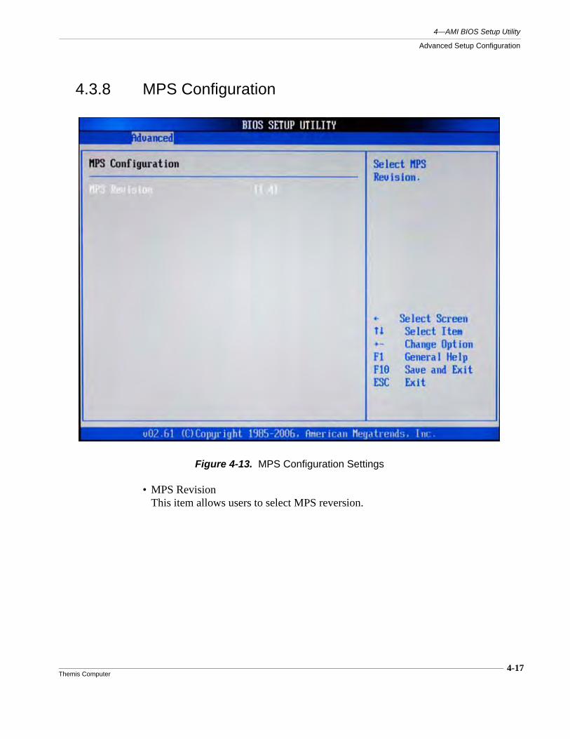
4-17Themis Computer
4—AMI BIOS Setup Utility
Advanced Setup Configuration
4.3.8 MPS Configuration
• MPS RevisionThis item allows users to select MPS reversion.
Figure 4-13. MPS Configuration Settings
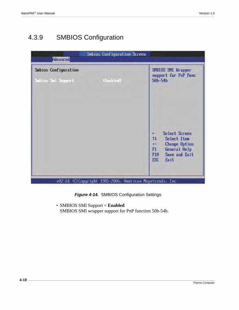
4-18Themis Computer
NanoPAK® User Manual Version 1.0
4.3.9 SMBIOS Configuration
• SMBIOS SMI Support = EnabledSMBIOS SMI wrapper support for PnP function 50h-54h.
Figure 4-14. SMBIOS Configuration Settings
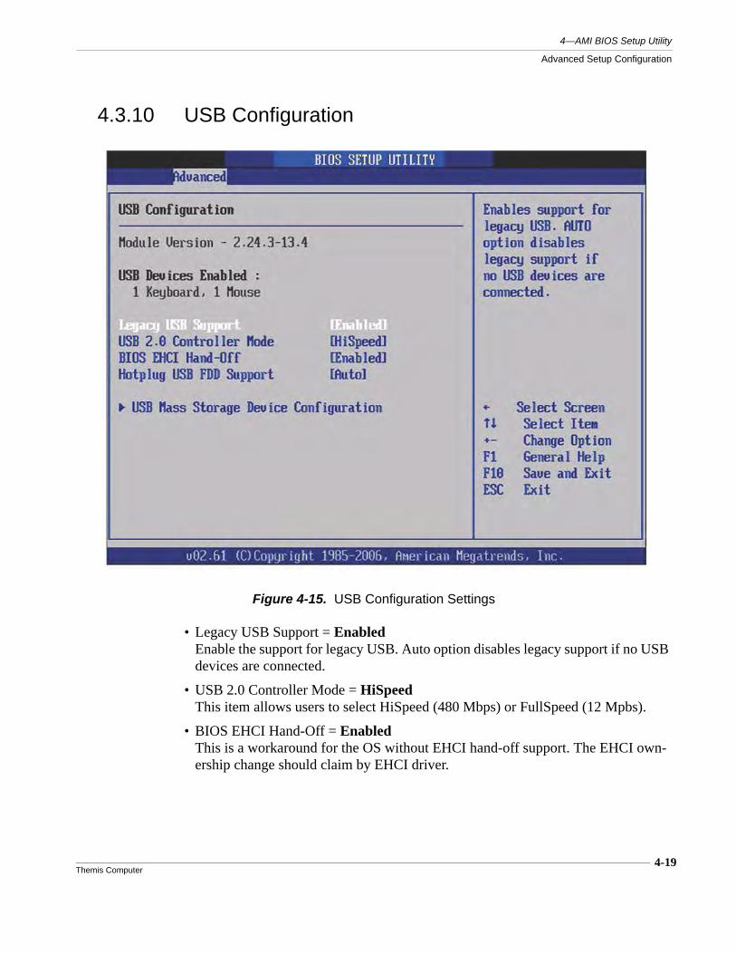
4-19Themis Computer
4—AMI BIOS Setup Utility
Advanced Setup Configuration
4.3.10 USB Configuration
• Legacy USB Support = EnabledEnable the support for legacy USB. Auto option disables legacy support if no USB devices are connected.
• USB 2.0 Controller Mode = HiSpeedThis item allows users to select HiSpeed (480 Mbps) or FullSpeed (12 Mpbs).
• BIOS EHCI Hand-Off = EnabledThis is a workaround for the OS without EHCI hand-off support. The EHCI own-ership change should claim by EHCI driver.
Figure 4-15. USB Configuration Settings
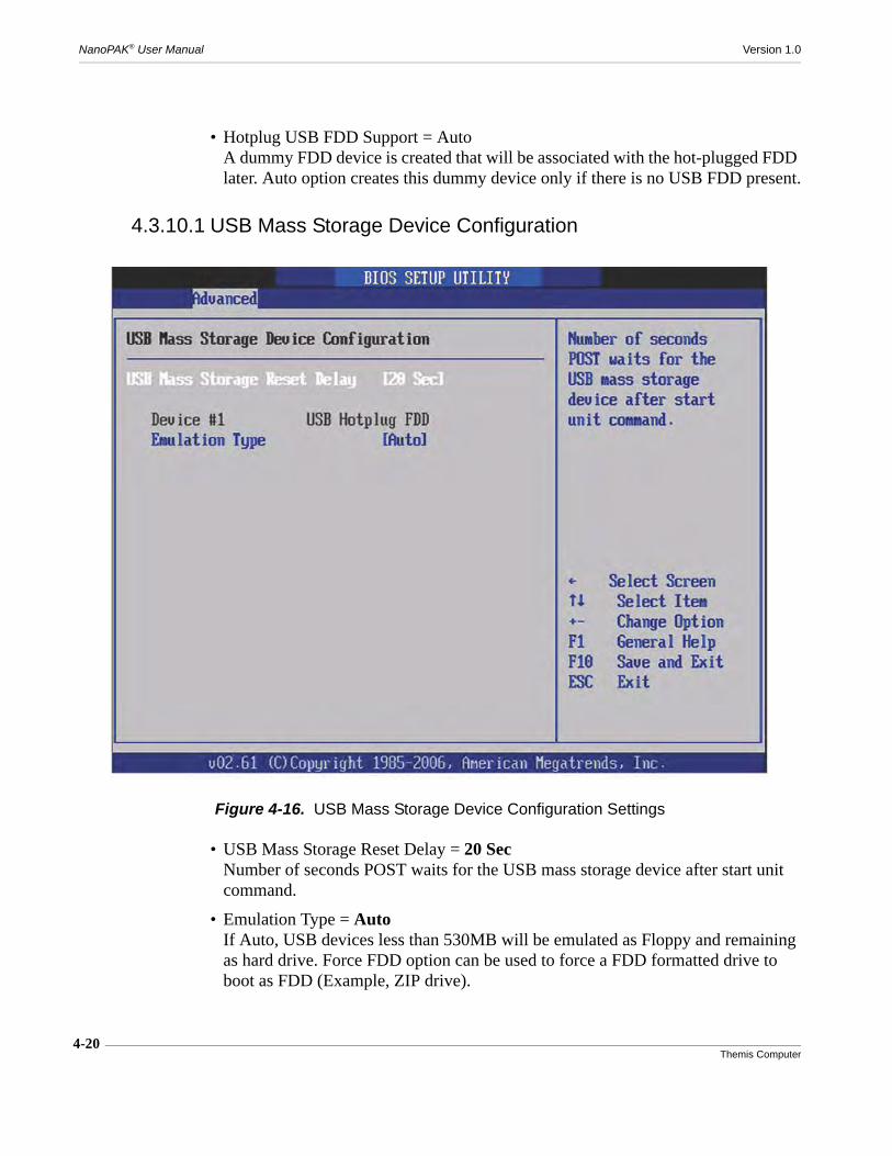
4-20Themis Computer
NanoPAK® User Manual Version 1.0
• Hotplug USB FDD Support = AutoA dummy FDD device is created that will be associated with the hot-plugged FDD later. Auto option creates this dummy device only if there is no USB FDD present.
4.3.10.1 USB Mass Storage Device Configuration
• USB Mass Storage Reset Delay = 20 SecNumber of seconds POST waits for the USB mass storage device after start unit command.
• Emulation Type = AutoIf Auto, USB devices less than 530MB will be emulated as Floppy and remaining as hard drive. Force FDD option can be used to force a FDD formatted drive to boot as FDD (Example, ZIP drive).
Figure 4-16. USB Mass Storage Device Configuration Settings
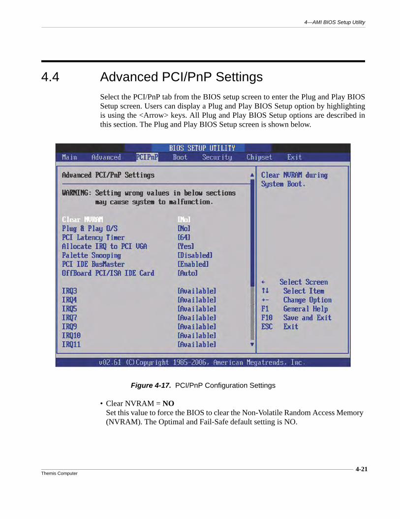
4-21Themis Computer
4—AMI BIOS Setup Utility
4.4 Advanced PCI/PnP SettingsSelect the PCI/PnP tab from the BIOS setup screen to enter the Plug and Play BIOSSetup screen. Users can display a Plug and Play BIOS Setup option by highlightingis using the <Arrow> keys. All Plug and Play BIOS Setup options are described inthis section. The Plug and Play BIOS Setup screen is shown below.
• Clear NVRAM = NOSet this value to force the BIOS to clear the Non-Volatile Random Access Memory (NVRAM). The Optimal and Fail-Safe default setting is NO.
Figure 4-17. PCI/PnP Configuration Settings

4-22Themis Computer
NanoPAK® User Manual Version 1.0
• Plug & Play O/S = NOwhen set to NO, the BIOS configures all devices in the system. If set to YES, and the OS supports Plug & Play, then rebooting the system is not required after the OS finishes configuration of the plug and play devices.
• PCI Latency TimerValue in units of PCI clocks for PCI device latency timer register.
• Allocate IRQ to PCI VGA = YESWhen to ES will assign IRQ to PCI VGA card if the card requests an IRQ. When set to NO the BIOS will not assign an IRQ to PCI VGA card even if the card requests it.
• Palette Snooping = DisabledThis item is designed to solve problems caused by some non-standard VGA cards.
• PCI IDE BusMaster = EnabledWhen set to enable BIOS, it uses PCI bus mastering for reading/writing to IDE devices.
• OffBoard PCI/ISA IDE Card = AutoSome PCI IDE cards may require this to be set to the PCI slot number that is hold-ing the card. When set to Auto, it will work for most PCI IDE cards.
• IRQ3 / 4 / 5 / 7 / 9 / 10 / 11This item allows users to respectively assign an interruptive type for IRQ3, 4, 5, 7, 9, 10, 11.
• DMA Channel0 / 1 / 3 / 5 / 6 / 7When set to Available, will allow specified DMA to be available to be used by PCI/PnP devices. When set to Reserved, will allow specified DMA to be reserved for use by legacy ISA devices.
• Reserved Memory SizeThis item allows users to reserve a specific size of memory block for legacy ISA devices.

4-23Themis Computer
4—AMI BIOS Setup Utility
4.5 Boot Settings
Figure 4-18. Boot Settings
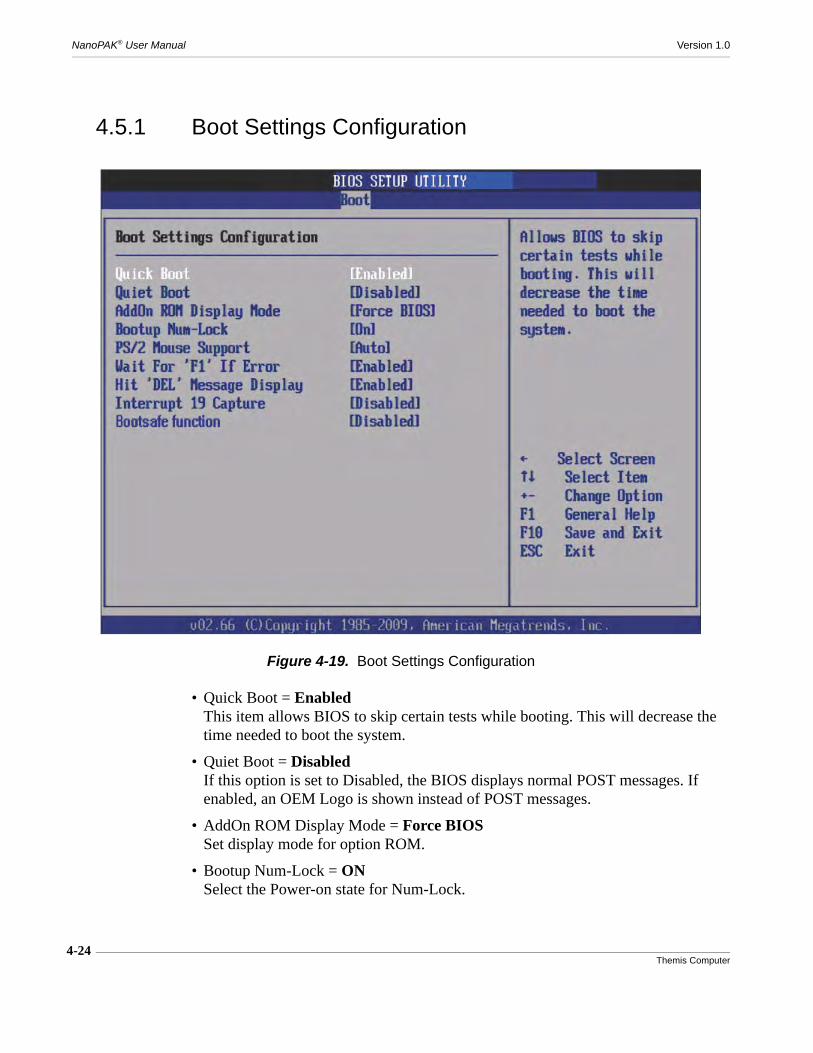
4-24Themis Computer
NanoPAK® User Manual Version 1.0
4.5.1 Boot Settings Configuration
• Quick Boot = EnabledThis item allows BIOS to skip certain tests while booting. This will decrease the time needed to boot the system.
• Quiet Boot = DisabledIf this option is set to Disabled, the BIOS displays normal POST messages. If enabled, an OEM Logo is shown instead of POST messages.
• AddOn ROM Display Mode = Force BIOSSet display mode for option ROM.
• Bootup Num-Lock = ONSelect the Power-on state for Num-Lock.
Figure 4-19. Boot Settings Configuration

4-25Themis Computer
4—AMI BIOS Setup Utility
Boot Settings
• PS/2 Mouse Support = AutoSelect support for PS/2 Mouse.
• Wait for “F1” If Error = EnabledWait for the F1 key to be pressed if an error occurs.
• Hit “DEL” Message Display = EnabledDisplays “Press DEL to run Setup in POST.”
• Interrupt 19 Capture = DisabledThis item allows option ROMs to trap interrupt 19.

4-26Themis Computer
NanoPAK® User Manual Version 1.0
4.6 Security SetupSelect Security from the main BIOS setup menu. All Security Setup options, such aspassword protection and virus protection are described in this section.
• Change supervisor / User PasswordSelect this option and press <ENTER> to access the sub menu, and then type in the password.
• Boot Sector Virus Protection = DisabledThe boot sector virus protection will warn if any program tries to write to the boot sector.
Figure 4-20. Security Settings
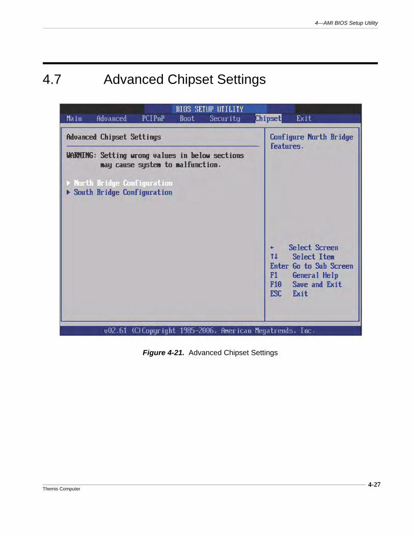
4-27Themis Computer
4—AMI BIOS Setup Utility
4.7 Advanced Chipset Settings
Figure 4-21. Advanced Chipset Settings
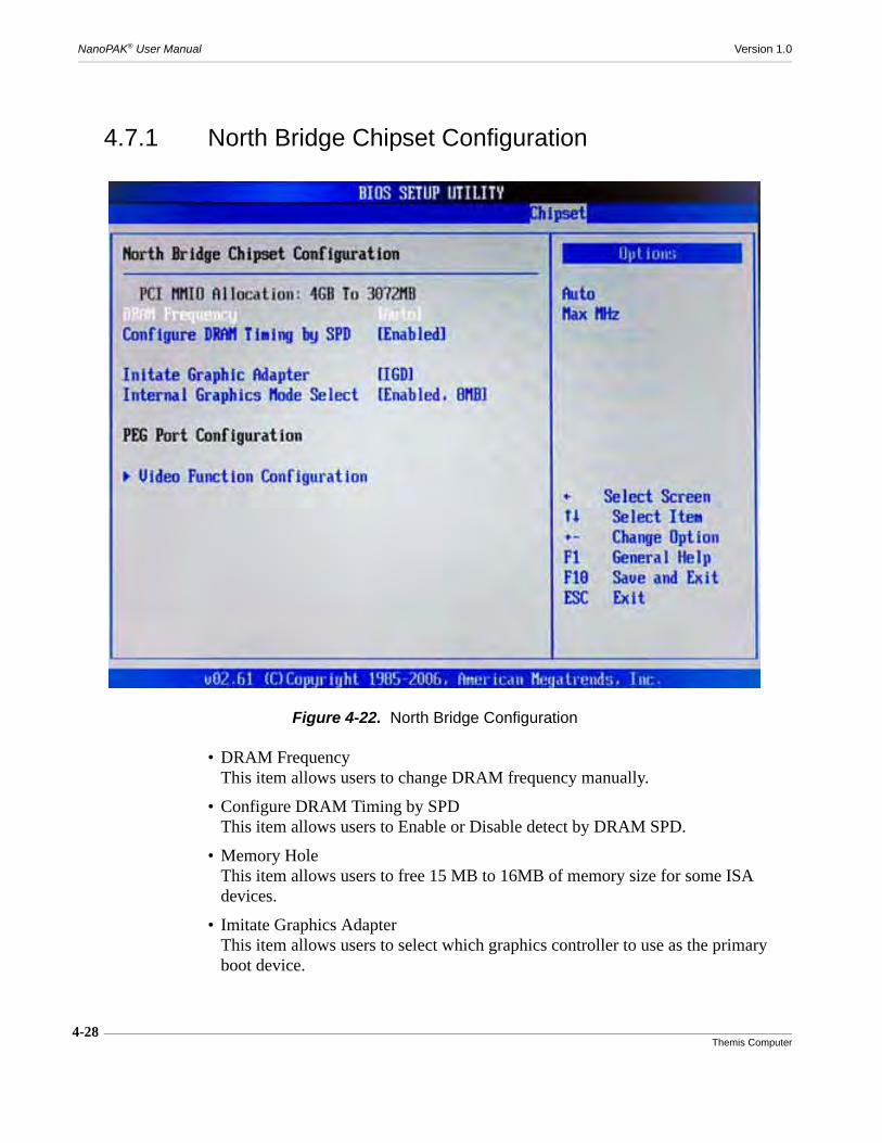
4-28Themis Computer
NanoPAK® User Manual Version 1.0
4.7.1 North Bridge Chipset Configuration
• DRAM FrequencyThis item allows users to change DRAM frequency manually.
• Configure DRAM Timing by SPDThis item allows users to Enable or Disable detect by DRAM SPD.
• Memory HoleThis item allows users to free 15 MB to 16MB of memory size for some ISA devices.
• Imitate Graphics AdapterThis item allows users to select which graphics controller to use as the primary boot device.
Figure 4-22. North Bridge Configuration
4-29Themis Computer
4—AMI BIOS Setup Utility
Advanced Chipset Settings
• Internal Graphics Mode SelectSelect the amount of system memory that can be used by the internal graphics device.
• DVMT Mode SelectDisplays the active system memory mode.
• DVMT / FIXED MemorySpecify the amount of DVMT / FIXED system memory to allocate for video mem-ory.
• Boot Display DeviceSelect boot display device at POST stage.
• Flat Panel TypeThis item allows users to select panel resolution.
• Spread Spectrum ClockThis item allows users to Enable or Disable the Spread Spectrum clock.
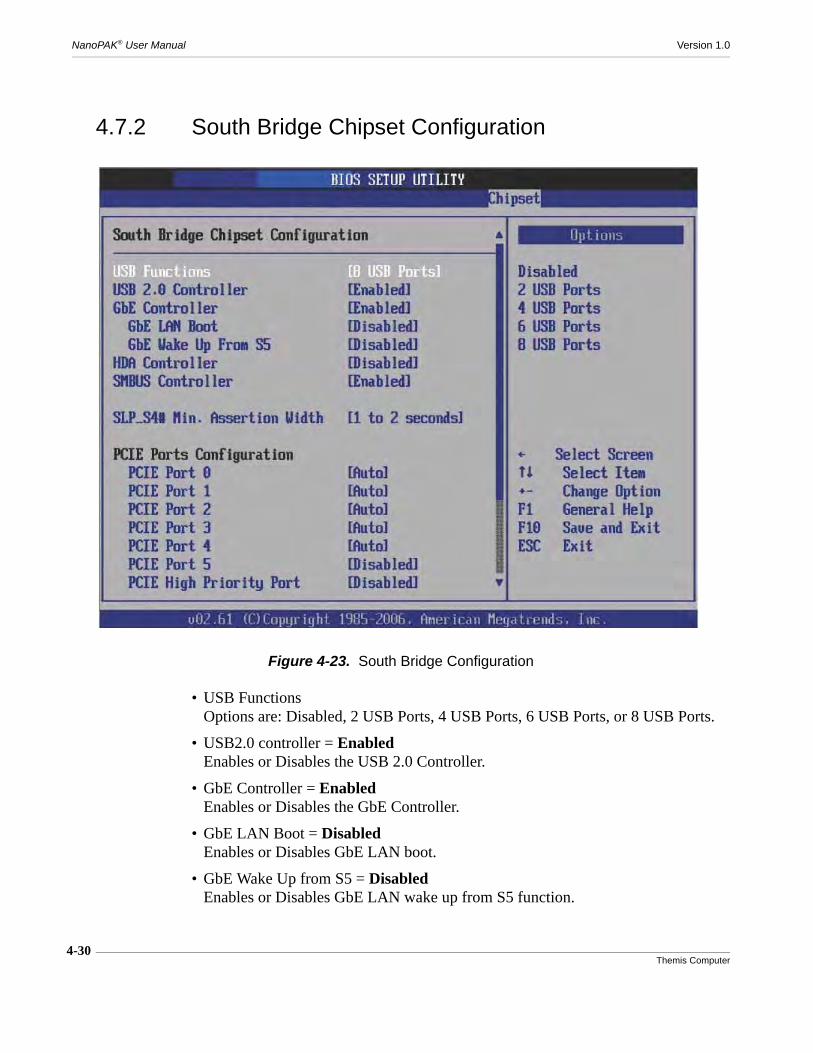
4-30Themis Computer
NanoPAK® User Manual Version 1.0
4.7.2 South Bridge Chipset Configuration
• USB FunctionsOptions are: Disabled, 2 USB Ports, 4 USB Ports, 6 USB Ports, or 8 USB Ports.
• USB2.0 controller = EnabledEnables or Disables the USB 2.0 Controller.
• GbE Controller = EnabledEnables or Disables the GbE Controller.
• GbE LAN Boot = DisabledEnables or Disables GbE LAN boot.
• GbE Wake Up from S5 = DisabledEnables or Disables GbE LAN wake up from S5 function.
Figure 4-23. South Bridge Configuration

4-31Themis Computer
4—AMI BIOS Setup Utility
Advanced Chipset Settings
• HDA Controller = DisabledEnables or Disables the HDA Controller
• SMBUS Controller = DisabledEnables or Disables the SMBUS Controller
• SLP_S4# Min. Assertion WidthThis item allows users to set a delay of sorts.
• PCIE Port 0 / 1 / 2 / 3 / 4This item allows users to configure PCIE Ports.
• PCIE High Priority Port = DisabledThis item allows users to set the highest priority PCIE port.
• PCIE Port 0 / 1 / 2 / 3 / 4 IOxAPICThis item allows users to Enable or Disable PCIE port’s IOxAPIC

4-32Themis Computer
NanoPAK® User Manual Version 1.0
4.8 Exit Options
4.8.1 Save Changes and Exit
When users have completed system configuration, select this option to save changes,exit BIOS setup menu and reboot the computer to take effect of all system configura-tion parameters.
1. Select Save Changes and Exit from the Exit menu and press <Enter>. The fol-lowing message appears: Save Configuration Changes and Exit Now? [Ok][Cancel]
Figure 4-24. Exit Options Screen

4-33Themis Computer
4—AMI BIOS Setup Utility
Exit Options
2. Select [Ok] or [Cancel].
4.8.2 Discard Changes and Exit
Select this option to quit Setup without making any permanent changes to the systemconfiguration.
1. Select Discard Changes and Exit from the Exit menu and press <Enter>. Thefollowing message appears: Discard Changes and Exit Setup Now? [Ok][Cancel].
2. Select [Ok] or [Cancel].
4.8.3 Load Optimal Defaults
The BIOS automatically configures all setup items to optimal settings when usersselect this option. Optimal Defaults are designed for maximum system performance,but may not work best for all computer applications. In particular, do not use theOptimal Defaults if the user’s computer is experiencing system configuration prob-lems.
1. Select Load Optimal Defaults from the Exit menu and press <Enter>. The fol-lowing message appears: Load Optimal Defaults? [Ok] [Cancel].
2. Select [Ok] to load Optimal defaults
4.8.4 Load Fail-Safe Defaults
The BIOS automatically configures all setup options to fail-safe settings when usersselect this option. Fail-Safe Defaults are designed for maximum system stability, butnot maximum performance. Select Fail-Safe Defaults if the user’s computer is expe-riencing system configuration problems.
1. Select Load Fail-Safe Defaults from the Exit menu and press <Enter>. Thefollowing message appears: Load Fail-Safe Defaults? [OK] [Cancel].
2. Select [Ok] to load Fail-Safe defaults.

4-34Themis Computer
NanoPAK® User Manual Version 1.0

A-1Themis Computer
A
Connector Pinouts, Signals and Solder Beads
A.1 J1 Pinouts and Signals
The prominent feature of the NanoPAK® front panel is the connector J1 which pro-vides all power and input/output connections for the system. This connector, a Cris-tek 69-pin connector, part number C42-01015-069, is shown in Figure A-1. The pinnumber diagram is in Figure A-2 on page A-2.
Table A-1 lists pinouts and signal definitions for J1, separating the pinouts for thoseunits with SATA capability on the left, and those units with no SATA capability onthe right.
Figure A-1. NanoPAK® Front Panel
Appendix
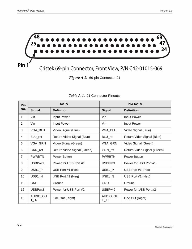
A-2Themis Computer
NanoPAK® User Manual Version 1.0
Figure A-2. 69-pin Connector J1
Pin 1
694724
4825
Cristek 69-pin Connector, Front View, P/N C42-01015-069
Table A-1. J1 Connector Pinouts
PinNo.
SATA NO SATA
Signal Definition Signal Definition
1 Vin Input Power Vin Input Power
2 Vin Input Power Vin Input Power
3 VGA_BLU Video Signal (Blue) VGA_BLU Video Signal (Blue)
4 BLU_ret Return Video Signal (Blue) BLU_ret Return Video Signal (Blue)
5 VGA_GRN Video Signal (Green) VGA_GRN Video Signal (Green)
6 GRN_ret Return Video Signal (Green) GRN_ret Return Video Signal (Green)
7 PWRBTN Power Button PWRBTN Power Button
8 USBPwr1 Power for USB Port #1 USBPwr1 Power for USB Port #1
9 USB1_P USB Port #1 (Pos) USB1_P USB Port #1 (Pos)
10 USB1_N USB Port #1 (Neg) USB1_N USB Port #1 (Neg)
11 GND Ground GND Ground
12 USBPwr2 Power for USB Port #2 USBPwr2 Power for USB Port #2
13AUDIO_OUT_ R
Line Out (Right)AUDIO_OUT_ R
Line Out (Right)

A-3Themis Computer
A—Connector Pinouts, Signals and Solder Beads
J1 Pinouts and Signals
14
Ser0 (RSTA/TXDA+)ORGPO2
Shared Ser0 RS232 RTSAORRS422/RS485 TXDA+ or GPO2
Ser0RS232 RTSAorRS422/RS485 TXDA+
15 Ser4RS232 TXDA or RS422/RS485 TXDA-
Ser4RS232 TXDA or RS422/RS485 TXDA-
16
Ser1(CTSA/RXDA+)ORGPI2
Shared Ser1 RS232 CTSA/RS422/RS485 RXDA+ORGPI2
Ser1RS232 CTSA or RS422/RS485 RXDA+
17 Ser5RS232 RXDA or RS422/RS485 RXDA-
Ser5RS232 RXDA or RS422/RS485 RXDA-
18 SATA_TX_N SATA XMIT (Neg) GPO2 General Purpose Output #2
19 GND Ground GND Ground
20 SATA_TX_P SATA XMIT (Pos) GPO3 General Purpose Output #3
21 GPO0 General Purpose Output #0 GPO0 General Purpose Output #0
22 GPI0 General Purpose Input #0 GPI0 General Purpose Input #0
23 MDI3_P GBE MDI3 Signal (Pos) MDI3_P GBE MDI3 Signal (Pos)
24 MDI3_N GBE MDI3 Signal (Neg) MDI3_N GBE MDI3 Signal (Neg)
25 GND Ground GND Ground
26 GND Ground GND Ground
27 Vsync Video Vertical Sync Signal Vsync Video Vertical Sync Signal
28 HV_Return Video Sync Return HV_Return Video Sync Return
29 Hsync Video Horizontal Sync Signal Hsync Video Horizontal Sync Signal
30RED_Return
RED Video Signal ReturnRED_Return
RED Video Signal Return
31 VGA_RED RED Video Signal VGA_RED RED Video Signal
32 GND Ground GND Ground
33 USB0_P USB Port #0 (Pos) USB0_P USB Port #0 (Pos)
Table A-1. J1 Connector Pinouts (Continued)
PinNo.
SATA NO SATA
Signal Definition Signal Definition
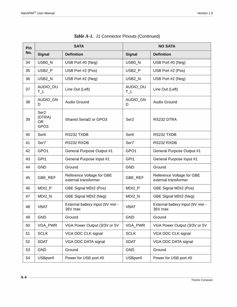
A-4Themis Computer
NanoPAK® User Manual Version 1.0
34 USB0_N USB Port #0 (Neg) USB0_N USB Port #0 (Neg)
35 USB2_P USB Port #2 (Pos) USB2_P USB Port #2 (Pos)
36 USB2_N USB Port #2 (Neg) USB2_N USB Port #2 (Neg)
37AUDIO_OUT_L
Line Out (Left)AUDIO_OUT_L
Line Out (Left)
38AUDIO_GND
Audio GroundAUDIO_GND
Audio Ground
39
Ser2 (DTRA)ORGPO3
Shared Serial2 or GPO3 Ser2 RS232 DTRA
40 Ser6 RS232 TXDB Ser6 RS232 TXDB
41 Ser7 RS232 RXDB Ser7 RS232 RXDB
42 GPO1 General Purpose Output #1 GPO1 General Purpose Output #1
43 GPI1 General Purpose Input #1 GPI1 General Purpose Input #1
44 GND Ground GND Ground
45 GBE_REFReference Voltage for GBE external transformer
GBE_REFReference Voltage for GBE external transformer
46 MDI2_P GBE Signal MDI2 (Pos) MDI2_P GBE Signal MDI2 (Pos)
47 MDI2_N GBE Signal MDI2 (Neg) MDI2_N GBE Signal MDI2 (Neg)
48 VBATExternal battery input (9V min - 36V max
VBATExternal battery input (9V min - 36V max
49 GND Ground GND Ground
50 VGA_PWR VGA Power Output (3/3V or 5V VGA_PWR VGA Power Output (3/3V or 5V
51 SCLK VGA DDC CLK signal SCLK VGA DDC CLK signal
52 SDAT VGA DDC DATA signal SDAT VGA DDC DATA signal
53 GND Ground GND Ground
54 USBpwr0 Power for USB port #0 USBpwr0 Power for USB port #0
Table A-1. J1 Connector Pinouts (Continued)
PinNo.
SATA NO SATA
Signal Definition Signal Definition

A-5Themis Computer
A—Connector Pinouts, Signals and Solder Beads
J1 Pinouts and Signals
55 USBpwr3 Power for USB port #3 USBpwr3 Power for USB port #3
56 USB3_P USB Port #3 (Pos) USB3_P USB Port #3 (Pos)
57 USB3_N USB Port #3 (Neg) USB3_N USB Port #3 (Neg)
58 GND Ground GND Ground
59AUDIO_IN_R
MIC In or Line In (Right)AUDIO_IN_R
MIC In or Line In (Right)
60AUDIO_GND
Audio GroundAUDIO_GND
Audio Ground
61AUDIO_IN_L
MIC In or Line In (Left)AUDIO_IN_L
MIC In or Line In (Left)
62Ser3 (DC-DA) - GPI3
Shared Serial3 or GPI3 Ser3 RS232 DCDA
63SATA_RX_N
SATA Receive (Neg) GPI2 General Purpose Input #2
64 GND Ground GND Ground
65 SATA_RX_P SATA Receive (Pos) GPI3 General Purpose Input #3
66 MDI0_P GBE Signal MDI0 (Pos) MDI0_P GBE Signal MDI0 (Pos)
67 MDI0_N GBE_Signal MDI0 (Neg) MDI0_N GBE_Signal MDI0 (Neg)
68 MDI1_P GBE Signal MDI1 (Pos) MDI1_P GBE Signal MDI1 (Pos)
69 MDI1_N GBE Signal MDI1 (Neg) MDI1_N GBE Signal MDI1 (Neg)
Table A-1. J1 Connector Pinouts (Continued)
PinNo.
SATA NO SATA
Signal Definition Signal Definition
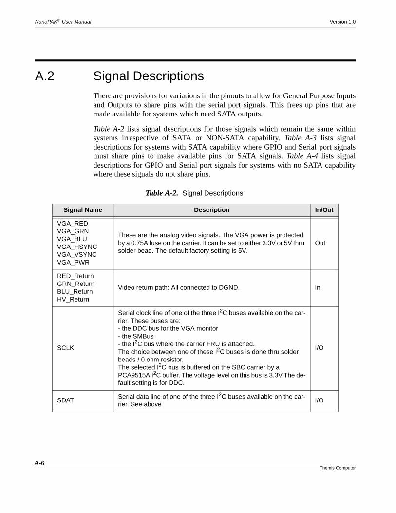
A-6Themis Computer
NanoPAK® User Manual Version 1.0
A.2 Signal DescriptionsThere are provisions for variations in the pinouts to allow for General Purpose Inputsand Outputs to share pins with the serial port signals. This frees up pins that aremade available for systems which need SATA outputs.
Table A-2 lists signal descriptions for those signals which remain the same withinsystems irrespective of SATA or NON-SATA capability. Table A-3 lists signaldescriptions for systems with SATA capability where GPIO and Serial port signalsmust share pins to make available pins for SATA signals. Table A-4 lists signaldescriptions for GPIO and Serial port signals for systems with no SATA capabilitywhere these signals do not share pins.
Table A-2. Signal Descriptions
Signal Name Description In/Out
VGA_REDVGA_GRNVGA_BLUVGA_HSYNCVGA_VSYNCVGA_PWR
These are the analog video signals. The VGA power is protected by a 0.75A fuse on the carrier. It can be set to either 3.3V or 5V thru solder bead. The default factory setting is 5V.
Out
RED_ReturnGRN_ReturnBLU_ReturnHV_Return
Video return path: All connected to DGND. In
SCLK
Serial clock line of one of the three I2C buses available on the car-rier. These buses are:- the DDC bus for the VGA monitor- the SMBus- the I2C bus where the carrier FRU is attached.The choice between one of these I2C buses is done thru solder beads / 0 ohm resistor.The selected I2C bus is buffered on the SBC carrier by a PCA9515A I2C buffer. The voltage level on this bus is 3.3V.The de-fault setting is for DDC.
I/O
SDATSerial data line of one of the three I2C buses available on the car-rier. See above
I/O
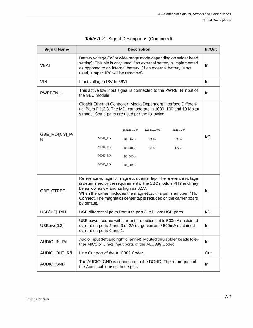
A-7Themis Computer
A—Connector Pinouts, Signals and Solder Beads
Signal Descriptions
VBAT
Battery voltage (3V or wide range mode depending on solder bead setting). This pin is only used if an external battery is implemented as opposed to an internal battery. (If an external battery is not used, jumper JP6 will be removed).
In
VIN Input voltage (18V to 36V) In
PWRBTN_LThis active low input signal is connected to the PWRBTN input of the SBC module.
In
GBE_MDI[0:3]_P/N
Gigabit Ethernet Controller: Media Dependent Interface Differen-tial Pairs 0,1,2,3. The MDI can operate in 1000, 100 and 10 Mbits/s mode. Some pairs are used per the following:
I/O
GBE_CTREF
Reference voltage for magnetics center tap. The reference voltage is determined by the requirement of the SBC module PHY and may be as low as 0V and as high as 3.3V.When the carrier includes the magnetics, this pin is an open / No Connect. The magnetics center tap is included on the carrier board by default.
In
USB[0:3]_P/N USB differential pairs Port 0 to port 3. All Host USB ports. I/O
USBpwr[0:3]USB power source with current protection set to 500mA sustained current on ports 2 and 3 or 2A surge current / 500mA sustained current on ports 0 and 1.
In
AUDIO_IN_R/LAudio Input (left and right channel). Routed thru solder beads to ei-ther MIC1 or Line1 input ports of the ALC889 Codec.
In
AUDIO_OUT_R/L Line Out port of the ALC889 Codec. Out
AUDIO_GNDThe AUDIO_GND is connected to the DGND. The return path of the Audio cable uses these pins.
In
Table A-2. Signal Descriptions (Continued)
Signal Name Description In/Out
1000 Base T 100 Base TX 10 Base T
MDI0_P/N B1_DA+/- TX+/- TX+/-
MDI1_P/N B1_DB+/- RX+/- RX+/-
MDI2_P/N B1_DC+/-
MDI3_P/N B1_DD+/-
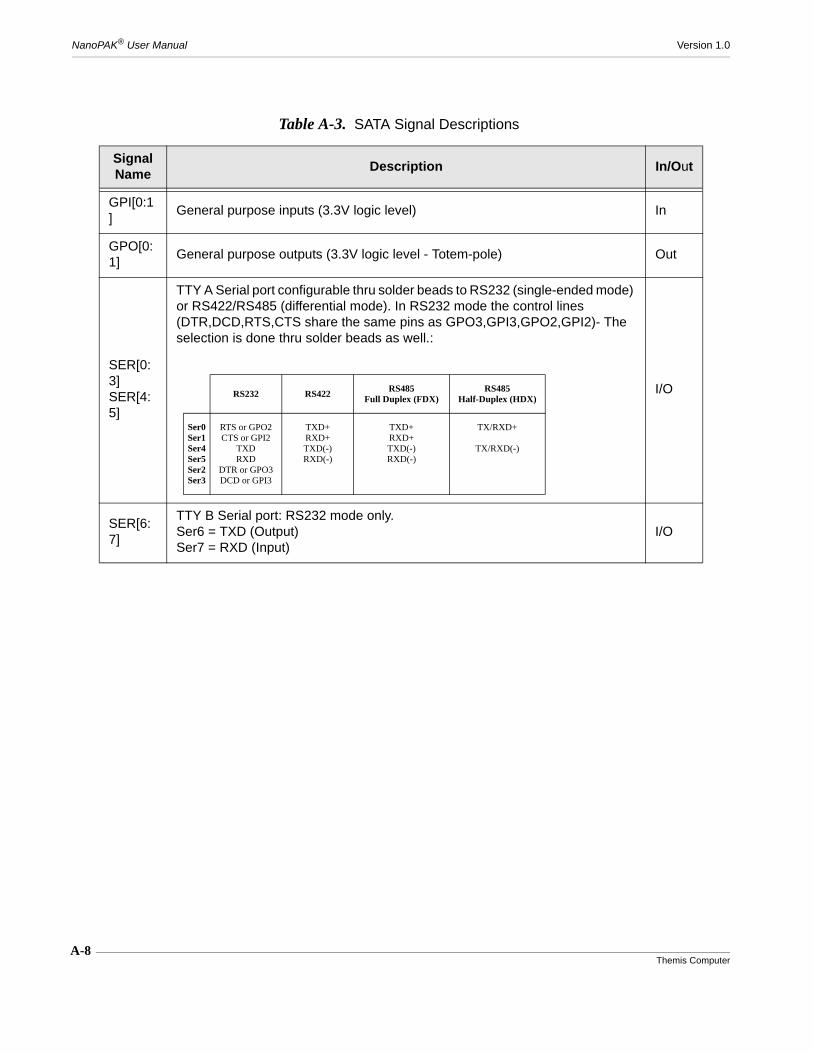
A-8Themis Computer
NanoPAK® User Manual Version 1.0
Table A-3. SATA Signal Descriptions
Signal Name
Description In/Out
GPI[0:1]
General purpose inputs (3.3V logic level) In
GPO[0:1]
General purpose outputs (3.3V logic level - Totem-pole) Out
SER[0:3]SER[4:5]
TTY A Serial port configurable thru solder beads to RS232 (single-ended mode) or RS422/RS485 (differential mode). In RS232 mode the control lines (DTR,DCD,RTS,CTS share the same pins as GPO3,GPI3,GPO2,GPI2)- The selection is done thru solder beads as well.:
I/O
SER[6:7]
TTY B Serial port: RS232 mode only.Ser6 = TXD (Output)Ser7 = RXD (Input)
I/O
RS232 RS422RS485
Full Duplex (FDX)RS485
Half-Duplex (HDX)
Ser0Ser1Ser4Ser5Ser2Ser3
RTS or GPO2CTS or GPI2
TXDRXD
DTR or GPO3DCD or GPI3
TXD+RXD+TXD(-)RXD(-)
TXD+RXD+TXD(-)RXD(-)
TX/RXD+
TX/RXD(-)
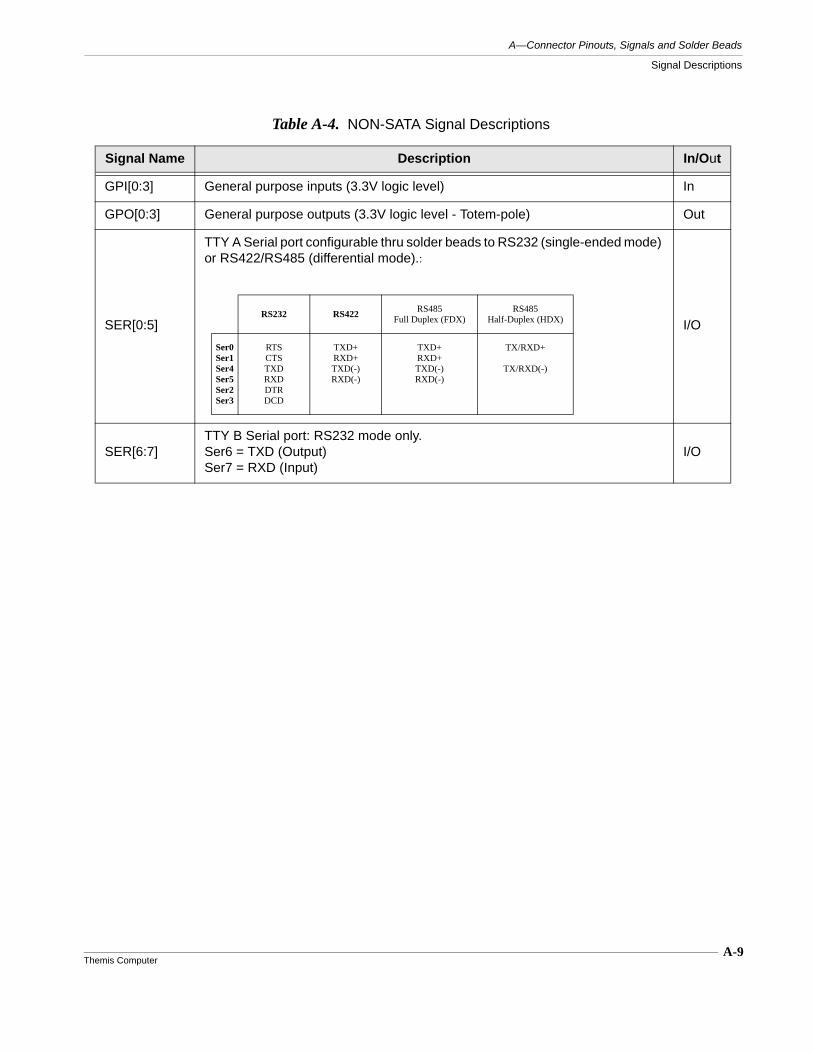
A-9Themis Computer
A—Connector Pinouts, Signals and Solder Beads
Signal Descriptions
Table A-4. NON-SATA Signal Descriptions
Signal Name Description In/Out
GPI[0:3] General purpose inputs (3.3V logic level) In
GPO[0:3] General purpose outputs (3.3V logic level - Totem-pole) Out
SER[0:5]
TTY A Serial port configurable thru solder beads to RS232 (single-ended mode) or RS422/RS485 (differential mode).:
I/O
SER[6:7]TTY B Serial port: RS232 mode only.Ser6 = TXD (Output)Ser7 = RXD (Input)
I/O
RS232 RS422RS485
Full Duplex (FDX)RS485
Half-Duplex (HDX)
Ser0Ser1Ser4Ser5Ser2Ser3
RTSCTSTXDRXDDTRDCD
TXD+RXD+TXD(-)RXD(-)
TXD+RXD+TXD(-)RXD(-)
TX/RXD+
TX/RXD(-)
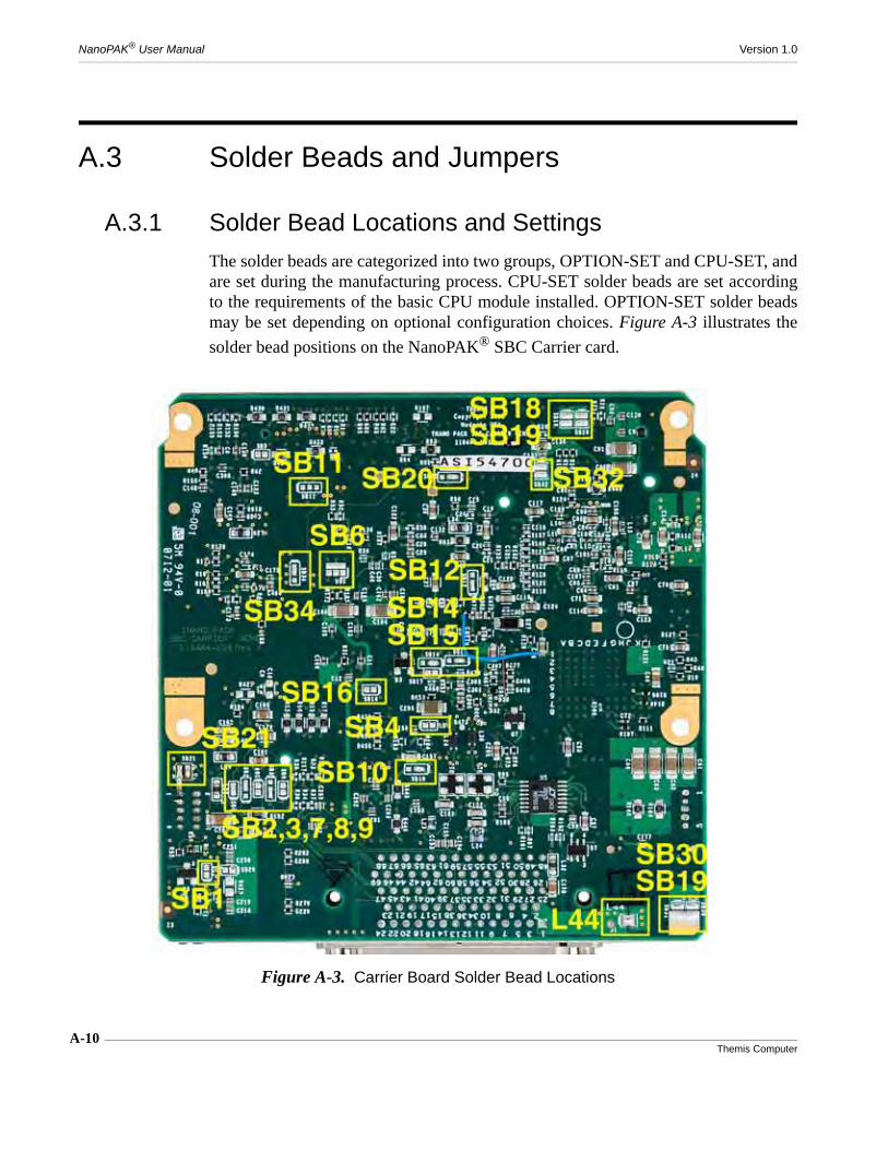
NanoPAK® User Manual Version 1.0
A-10Themis Computer
A.3 Solder Beads and Jumpers
A.3.1 Solder Bead Locations and Settings
The solder beads are categorized into two groups, OPTION-SET and CPU-SET, andare set during the manufacturing process. CPU-SET solder beads are set accordingto the requirements of the basic CPU module installed. OPTION-SET solder beadsmay be set depending on optional configuration choices. Figure A-3 illustrates the
solder bead positions on the NanoPAK® SBC Carrier card.
Figure A-3. Carrier Board Solder Bead Locations

A-11Themis Computer
A—Connector Pinouts, Signals and Solder Beads
Solder Beads and Jumpers
Table A-5 below lists the solder beads, their descriptions and their default settings.
Table A-5. Solder Bead Settings
Name Category DescriptionFactory Default Setting
SB1 CPU-SET
This solder bead is not used as a solder bead. It is in fact two contacts that should be momentarily shorted to clear the CMOS powered by the battery. Except for special locked sit-uation caused by heavy corruption of the CMOS content, there should not be a reason to use it. Also, there is another way to clear the CMOS by removing the battery from the bat-tery holder on the Add-on card.SB1 SHORTED: Clear the CMOS powered by the battery.
SB1: NEVER INSTALLED
SB2, SB3
OPTION-SET
Used to set the serial link of the TTY-A port in half-duplex mode or full-duplex mode. Half-duplex will only be used when working in single pair mode in RS485 mode. Otherwise, the full-duplex mode should be selected.SB2,SB3 Set to 2-3: Full-duplexSB2,SB3 Set to 1-2: Half-duplex
SB2, SB3:Set to 2-3(Full-duplex)
SB4 CPU-SET
This solder-bead is used to implement an approximate 6 sec. delay in the turn-on time of the main 12V DC converter that provides the main power to the NanoPAK. It allows the emu-lation of a battery. This is only needed if there is no battery in the system or the SBC module is not the Themis AMD SBC module revX or revY.SB4 NOT INSTALLED: 12V power is turned-on as soon as a valid Vin input voltage is applied to the unit.SB4 INSTALLED: 12V power is turned on 6 sec. after a valid Vin input voltage is applied to the unit.
SB4:NOT INSTALLED(no 6s delay)
SB5 CPU-SET Not operational. Reserved for future use. SB5:NOT INSTALLED
SB6 CPU-SET
Used to set the FRU I2C address.SB6 4-1 controls address bit 0 (ON means 0, OFF means 1)SB6 4-2 controls address bit 1 (ON means 0, OFF means 1)SB6 4-3 controls address bit 2 (ON means 0, OFF means 1)NONE INSTALLED (sets the FRU I2C address = 0xAE/0xAF)
SB6:NONE IN-STALLED
SB7 OPTION-SET
Used to select the protocol on the TTY-A port (RS232 versus RS485/422).SB7 NOT INSTALLED: RS422 or RS485 protocolSB7 INSTALLED: RS232
SB7:INSTALLED(RS-232)
SB8 OPTION-SET
Used to provide a termination on the receiver side. (Only ap-plies when in RS422 or RS485 mode.)SB8 NOT INSTALLED: No receiver termination.SB8 INSTALLED: Receiver termination ON.
SB8:NOT INSTALLED

A-12Themis Computer
NanoPAK® User Manual Version 1.0
SB9 OPTION-SET
Used to connect the termination on the transmitter side. (Only applies when in RS422 or RS485 mode.SB9 NOT INSTALLED: No transmitter termination.SB9 INSTALLED: Transmitter termination ON
SB9:NOT INSTALLED
SB10 CPU-SET
Used to select the power source provided on the VGA con-nector. The pin is protected by a resettable fuse.SB10 SET TO 1-2: 5VSB10 SET TO 2-3: 3.3V
SB10:1-2 (5V)
SB11 CPU-SET
Two signals, S3 and S4, indicate the sleep state of the SBC module. SB11 is used to define the effect of those states on the DC/DC converters. SB11 NOT INSTALLED: No effectSB11 SET TO 1-2: S3 active state can turn off the 12V/5V and 5V/3.3V convertersSB11 SET TO 2-3: S4 active state can turn off the 12V/5V and 5V/3.3V converters
SB11:NOT INSTALLED(No effect)
SB12, SB14, SB15, SB20
OPTION-SET
Used to set the AUDIO inputSB12,SB14,SB15,SB20 SET TO 1-2: select MIC1SB12,SB14,SB15,SB20 SET TO 2-3: select LINE1
SB12, SB14, SB15, SB20:1-2 (MIC1)
SB14 OPTION-SET See SB12 SB14
1-2 (MIC1)
SB15 OPTION-SET See SB12 SB15
1-2 (MIC1)
SB16 CPU-SET
Controls the effect of S3 or S4 on the 5V/3.3V DC/DC con-verter.SB16 INSTALLED: Allows S3 or S4 to disable the 5V/3.3V converter.SB16 NOT INSTALLED: Does not allow S3 or S4 to disable the 5V/3.3V converter
SB16:NOT INSTALLED
SB17 CPU-SET Close this solder bead to “fake” the VCC_RTC voltage from the 5VALW source.
SB17:NOT INSTALLED
Table A-5. Solder Bead Settings (Continued)
Name Category DescriptionFactory Default Setting
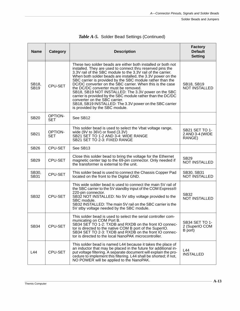
A-13Themis Computer
A—Connector Pinouts, Signals and Solder Beads
Solder Beads and Jumpers
SB18, SB19 CPU-SET
These two solder beads are either both installed or both not installed. They are used to connect thru reserved pins the 3.3V rail of the SBC module to the 3.3V rail of the carrier. When both solder beads are installed, the 3.3V power on the SBC carrier is provided by the SBC module rather than the DC/DC converter on the SBC carrier. When this is the case the DC/DC converter must be removed.SB18, SB19 NOT INSTALLED: The 3.3V power on the SBC carrier is provided by the SBC module rather than the DC/DC converter on the SBC carrier.SB18, SB19 INSTALLED: The 3.3V power on the SBC carrier is provided by the SBC module.
SB18, SB19NOT INSTALLED
SB20 OPTION-SET See SB12
SB21 OPTION-SET
This solder bead is used to select the Vbat voltage range, wide (9V to 36V) or fixed (3.3V)SB21 SET TO 1-2 AND 3-4: WIDE RANGESB21 SET TO 2-3: FIXED RANGE
SB21 SET TO 1-2 AND 3-4 (WIDE RANGE)
SB26 CPU-SET See SB13
SB29 CPU-SETClose this solder bead to bring the voltage for the Ethernet magnetic center tap to the 69-pin connector. Only needed if the transformer is external to the unit.
SB29 NOT INSTALLED
SB30, SB31 CPU-SET This solder bead is used to connect the Chassis Copper Pad
located on the front to the Digital GND.SB30, SB31NOT INSTALLED
SB32 CPU-SET
This wide solder bead is used to connect the main 5V rail of the SBC carrier to the 5V standby input of the COM Express® 220-pin connector.SB32 NOT INSTALLED: No 5V stby voltage provided to the SBC module.SB32 INSTALLED: The main 5V rail on the SBC carrier is the 5V stby voltage needed by the SBC module.
SB32NOT INSTALLED
SB34 CPU-SET
This solder bead is used to select the serial controller com-municating on COM Port B.SB34 SET TO 1-2: TXDB and RXDB on the front IO connec-tor is directed to the native COM B port of the SuperIO.SB34 SET TO 2-3: TXDB and RXDB on the front IO connec-tor is directed to the local NanoPAK microcontroller.
SB34 SET TO 1-2 (SuperIO COM B port)
L44 CPU-SET
This solder bead is named L44 because it takes the place of an inductor that may be placed in the future for additional in-put voltage filtering. A separate document will explain the pro-cedure to implement this filtering. L44 shall be shorted; if not, NO POWER will be applied to the NanoPAK.
L44INSTALLED
Table A-5. Solder Bead Settings (Continued)
Name Category DescriptionFactory Default Setting

A-14Themis Computer
NanoPAK® User Manual Version 1.0
Table A-6. Battery/LED Card Solder Bead Settings
Name Category DescriptionFactory Default Setting
SB13, SB26
CPU-SET Only ONE of those two solder beads shall be installed at any given time. They define what power range is applied to the logic on the add-on (Battery/LED) card (P/N 118445-L01) plugged into the Nanopack SBC carrier Gen2 (118446-L01 or 118447-L01).There are therefore two configurations
SB13 INSTALLED and SB26 NOT INSTALLED to apply 5V.SB13 NOT INSTALLED and SB26 INSTALLED to apply 3.3V.
The factory configuration shall be:SB13: NOT INSTALLED SB26: INSTALLED (3.3V)
SB13, SB26
SB26 See SB13 SB26

A—Connector Pinouts, Signals and Solder Beads
Solder Beads and Jumpers
A-15Themis Computer
A.3.2 Jumpers
A.3.2.1 Jumper JP1
Jumper JP1 is located on the left side of the front panel when facing the unit. It canbe accessed by removing the front bezel. JP1 is used to disconnect an on-board bat-tery, when installed, from the standby power circuit.
A.3.2.2 Jumper JP6
Jumper JP6 is located on the right side of the front panel when facing the unit. It canbe accessed by removing the front bezel. JP6 is used to disconnect the externalstandby power source from the standby power circuit.
Figure A-4. Carrier Board Jumper Locations
NanoPAK
JP1 Location JP6 Location
Bat
tery

NanoPAK® User Manual Version 1.0
A-16Themis Computer
Table A-7. Battery/LED Jumper Settings
Name DescriptionFactory Default Setting
JP1 This jumper is used to disconnect the battery on the LED/Battery board from any load. When the product is put on the shelf, this jumper should be removed
JP1:NOT INSTALLED
JP4,JP5,J6
This combination of jumpers and connector is used to set the Microcontroller in programming mode or operational mode.For operational mode: Install jumper on JP5 and a jumper across JP4.2 and J.6.1(On rev X of the PCB JP4.2 should be bent slightly. This will be fixed on the new revision)For programming mode:(need to ask Philip)
JP4,JP5,J6:JP5: INSTALLEDJP5, J6: TBD

B-1Themis Computer
B
Accessory Equipment
B.1 NanoPAK® Development KitThe NanoPAK® Development Kit contains a NanoPAK®, mounted on a metal base-board, and a breakout cable, packed in a hard shell fitted case. (See Figure B-1). The
baseboard, (see Figure B-2 on page B-2), serves as a heat sink (cold plate) and con-
Figure B-1. NanoPAK® Development Kit
Appendix
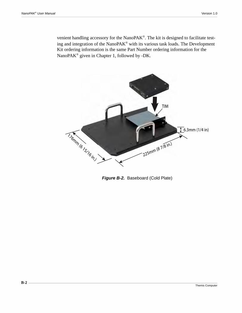
B-2Themis Computer
NanoPAK® User Manual Version 1.0
venient handling accessory for the NanoPAK®. The kit is designed to facilitate test-ing and integration of the NanoPAK® with its various task loads. The Development Kit ordering information is the same Part Number ordering information for the NanoPAK® given in Chapter 1, followed by -DK.
Figure B-2. Baseboard (Cold Plate)
225mm (8 7/8 in.)
176mm
(6 15/16 in.)
TIM
6.3mm (1/4 in)
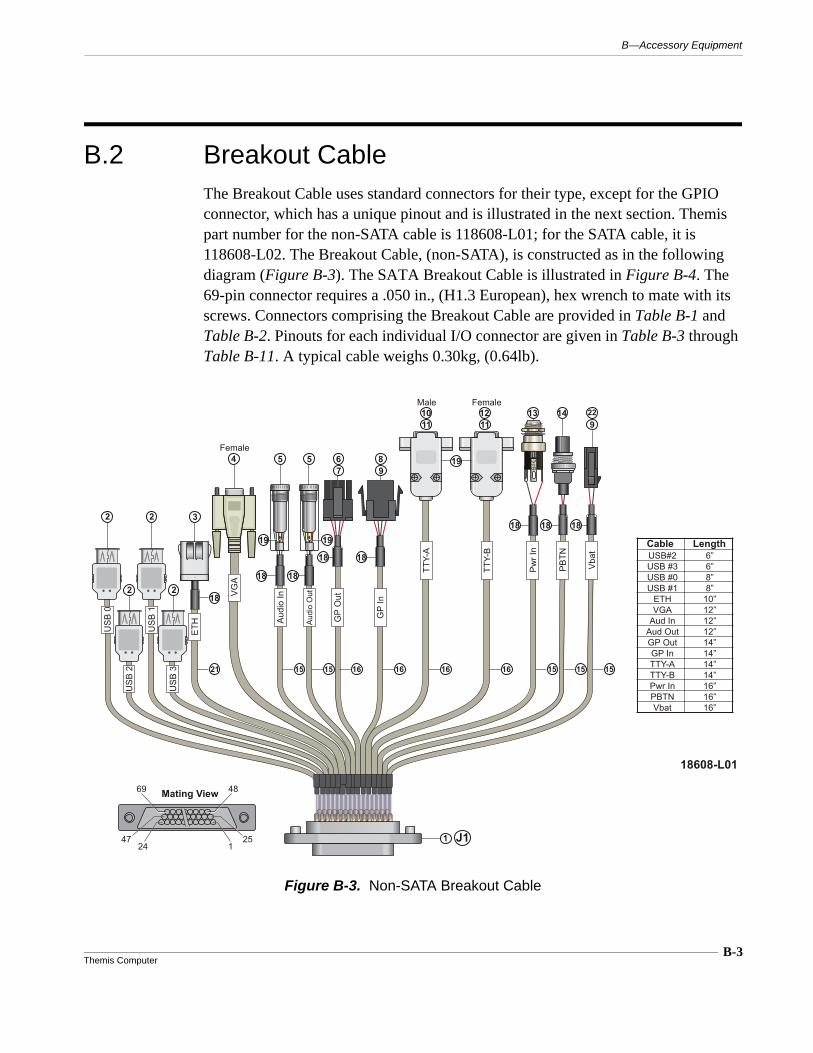
B-3Themis Computer
B—Accessory Equipment
B.2 Breakout CableThe Breakout Cable uses standard connectors for their type, except for the GPIO connector, which has a unique pinout and is illustrated in the next section. Themis part number for the non-SATA cable is 118608-L01; for the SATA cable, it is 118608-L02. The Breakout Cable, (non-SATA), is constructed as in the following diagram (Figure B-3). The SATA Breakout Cable is illustrated in Figure B-4. The 69-pin connector requires a .050 in., (H1.3 European), hex wrench to mate with its screws. Connectors comprising the Breakout Cable are provided in Table B-1 and Table B-2. Pinouts for each individual I/O connector are given in Table B-3 through Table B-11. A typical cable weighs 0.30kg, (0.64lb).
Figure B-3. Non-SATA Breakout Cable
1818
18
18
USB
2
USB
3
USB
0
Female
USB
1
ETH
VGA
Audi
o In
Audi
o O
ut
TTY-
A
FemaleMale
TTY-
B
PBTN
Pwr I
n
Vbat
GP
Out
GP
In
18608-L01
J1
2 2
2 2
3
4 5 5 67
89
1011
1211
13 14 229
1
S
USB#2USB #3USB #0USB #1
ETHVGA
Aud InAud OutGP OutGP InTTY-ATTY-BPwr InPBTNVbat
6”6”8”8”10”12”12”12”14”14”14”14”16”16”16”
Cable Length
18
18
19 19
18
18
19
69 48
2524 1
47
Mating View
21 15 15 16 16 16 16 15 15 15
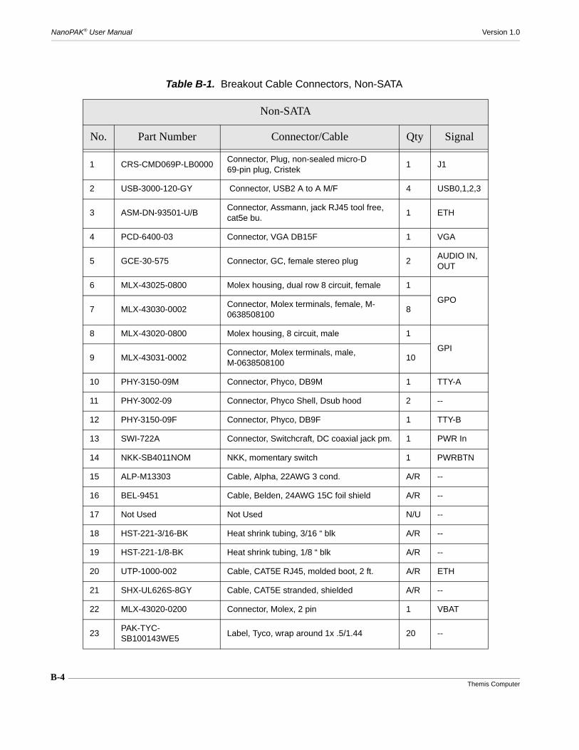
NanoPAK® User Manual Version 1.0
B-4Themis Computer
Table B-1. Breakout Cable Connectors, Non-SATA
Non-SATA
No. Part Number Connector/Cable Qty Signal
1 CRS-CMD069P-LB0000Connector, Plug, non-sealed micro-D 69-pin plug, Cristek
1 J1
2 USB-3000-120-GY Connector, USB2 A to A M/F 4 USB0,1,2,3
3 ASM-DN-93501-U/BConnector, Assmann, jack RJ45 tool free, cat5e bu.
1 ETH
4 PCD-6400-03 Connector, VGA DB15F 1 VGA
5 GCE-30-575 Connector, GC, female stereo plug 2AUDIO IN, OUT
6 MLX-43025-0800 Molex housing, dual row 8 circuit, female 1
GPO7 MLX-43030-0002
Connector, Molex terminals, female, M-0638508100
8
8 MLX-43020-0800 Molex housing, 8 circuit, male 1
GPI9 MLX-43031-0002
Connector, Molex terminals, male, M-0638508100
10
10 PHY-3150-09M Connector, Phyco, DB9M 1 TTY-A
11 PHY-3002-09 Connector, Phyco Shell, Dsub hood 2 --
12 PHY-3150-09F Connector, Phyco, DB9F 1 TTY-B
13 SWI-722A Connector, Switchcraft, DC coaxial jack pm. 1 PWR In
14 NKK-SB4011NOM NKK, momentary switch 1 PWRBTN
15 ALP-M13303 Cable, Alpha, 22AWG 3 cond. A/R --
16 BEL-9451 Cable, Belden, 24AWG 15C foil shield A/R --
17 Not Used Not Used N/U --
18 HST-221-3/16-BK Heat shrink tubing, 3/16 “ blk A/R --
19 HST-221-1/8-BK Heat shrink tubing, 1/8 “ blk A/R --
20 UTP-1000-002 Cable, CAT5E RJ45, molded boot, 2 ft. A/R ETH
21 SHX-UL626S-8GY Cable, CAT5E stranded, shielded A/R --
22 MLX-43020-0200 Connector, Molex, 2 pin 1 VBAT
23PAK-TYC-SB100143WE5
Label, Tyco, wrap around 1x .5/1.44 20 --

B-5Themis Computer
B—Accessory Equipment
Breakout Cable
Figure B-4. SATA Break Out Cable
1818
18
18
Female
VG
A
Aud
io In
Aud
io O
ut
TTY-
A
FemaleMale
TTY-
B
PB
TN
Pw
r In
Vba
t
GP
Out
GP
In
4 5 5 67
89
1011
1211
13 14 239
S
18
19 19
18
1817
1920
1186
08-L
02M
AI
Dat
e C
ode
SAT
A
US
B 2
US
B 3
US
B 0
US
B 1
ETH
Break out I/O cable
18608-L02
2 2
2 2
3
USB#2USB #3USB #0USB #1
ETHSATAVGA
Aud InAud OutGP OutGP InTTY-ATTY-BPwr InPBTNVbat
6”6”8”8”
10”10”12”12”12”14”14”14”14”16”16”16”
Cable Length
18
69 48
2524 1
47
Mating View
22
J11
21 15 16 15
Table B-2. Breakout Cable Connectors, SATA
SATA
No. Part Number Connector/Cable Qty Signal
1 CRS-CMD069P-LB0000Connector, Plug, non-sealed micro-D 69-pin plug, Cristek
1 J1
2 USB-3000-036-GY Connector, USB2 A to A M/F 4 USB0,1,2,3
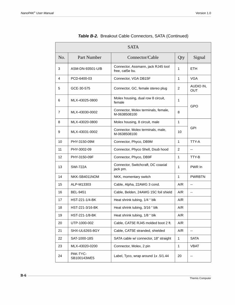
B-6Themis Computer
NanoPAK® User Manual Version 1.0
3 ASM-DN-93501-U/BConnector, Assmann, jack RJ45 tool free, cat5e bu.
1 ETH
4 PCD-6400-03 Connector, VGA DB15F 1 VGA
5 GCE-30-575 Connector, GC, female stereo plug 2AUDIO IN, OUT
6 MLX-43025-0800Molex housing, dual row 8 circuit, female
1
GPO
7 MLX-43030-0002Connector, Molex terminals, female, M-0638508100
8
8 MLX-43020-0800 Molex housing, 8 circuit, male 1
GPI9 MLX-43031-0002
Connector, Molex terminals, male, M-0638508100
10
10 PHY-3150-09M Connector, Phyco, DB9M 1 TTY-A
11 PHY-3002-09 Connector, Phyco Shell, Dsub hood 2 --
12 PHY-3150-09F Connector, Phyco, DB9F 1 TTY-B
13 SWI-722AConnector, Switchcraft, DC coaxial jack pm.
1 PWR In
14 NKK-SB4011NOM NKK, momentary switch 1 PWRBTN
15 ALP-M13303 Cable, Alpha, 22AWG 3 cond. A/R --
16 BEL-9451 Cable, Belden, 24AWG 15C foil shield A/R --
17 HST-221-1/4-BK Heat shrink tubing, 1/4 “ blk A/R
18 HST-221-3/16-BK Heat shrink tubing, 3/16 “ blk A/R
19 HST-221-1/8-BK Heat shrink tubing, 1/8 “ blk A/R
20 UTP-1000-002 Cable, CAT5E RJ45 molded boot 2 ft. A/R
21 SHX-UL626S-8GY Cable, CAT5E stranded, shielded A/R --
22 SAT-1000-18S SATA cable w/ connector, 18” straight 1 SATA
23 MLX-43020-0200 Connector, Molex, 2 pin 1 VBAT
24PAK-TYC-SB100143WE5
Label, Tyco, wrap around 1x .5/1.44 20 --
Table B-2. Breakout Cable Connectors, SATA (Continued)
SATA
No. Part Number Connector/Cable Qty Signal
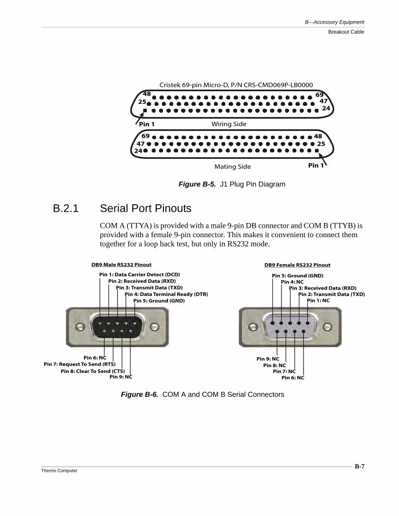
B-7Themis Computer
B—Accessory Equipment
Breakout Cable
B.2.1 Serial Port Pinouts
COM A (TTYA) is provided with a male 9-pin DB connector and COM B (TTYB) is provided with a female 9-pin connector. This makes it convenient to connect them together for a loop back test, but only in RS232 mode.
Figure B-5. J1 Plug Pin Diagram
Pin 1
694724
4825
Wiring Side
Pin 1
6947
24
4825
Mating Side
Cristek 69-pin Micro-D, P/N CRS-CMD069P-LB0000
Figure B-6. COM A and COM B Serial Connectors
DB9 Male RS232 Pinout
Pin 1: Data Carrier Detect (DCD)Pin 2: Received Data (RXD)
Pin 3: Transmit Data (TXD)Pin 4: Data Terminal Ready (DTR)
Pin 5: Ground (GND)
Pin 6: NCPin 7: Request To Send (RTS)
Pin 8: Clear To Send (CTS)Pin 9: NC
DB9 Female RS232 Pinout
Pin 1: NCPin 2: Transmit Data (TXD)
Pin 3: Received Data (RXD)Pin 4: NC
Pin 5: Ground (GND)
Pin 6: NCPin 7: NC
Pin 8: NCPin 9: NC
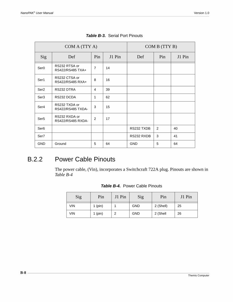
B-8Themis Computer
NanoPAK® User Manual Version 1.0
B.2.2 Power Cable Pinouts
The power cable, (Vin), incorporates a Switchcraft 722A plug. Pinouts are shown in Table B-4
Table B-3. Serial Port Pinouts
COM A (TTY A) COM B (TTY B)
Sig Def Pin J1 Pin Def Pin J1 Pin
Ser0RS232 RTSA orRS422/RS485 TXA+
7 14
Ser1RS232 CTSA orRS422/RS485 RXA+
8 16
Ser2 RS232 DTRA 4 39
Ser3 RS232 DCDA 1 62
Ser4RS232 TXDA orRS422/RS485 TXDA-
3 15
Ser5RS232 RXDA orRS422/RS485 RXDA-
2 17
Ser6 RS232 TXDB 2 40
Ser7 RS232 RXDB 3 41
GND Ground 5 64 GND 5 64
Table B-4. Power Cable Pinouts
Sig Pin J1 Pin Sig Pin J1 Pin
VIN 1 (pin) 1 GND 2 (Shell) 25
VIN 1 (pin) 2 GND 2 (Shell 26

B-9Themis Computer
B—Accessory Equipment
Breakout Cable
B.2.3 Power Button Pinout
The Power Button cable incorporates an NKK SPST Momentary-On switch, part number SP4011NOH-2F, which provides a way to restart the system without com-pletely shutting down power to the system.
Figure B-7. Power Connector
Switchcraft Plug 722A
Vin Connector
+
Pin-Shell
- +
Table B-5. Power Button Pinouts
Sig Pin J1 Pin Sig Pin J1 Pin
PwrBTN 1 7 GND 2 32
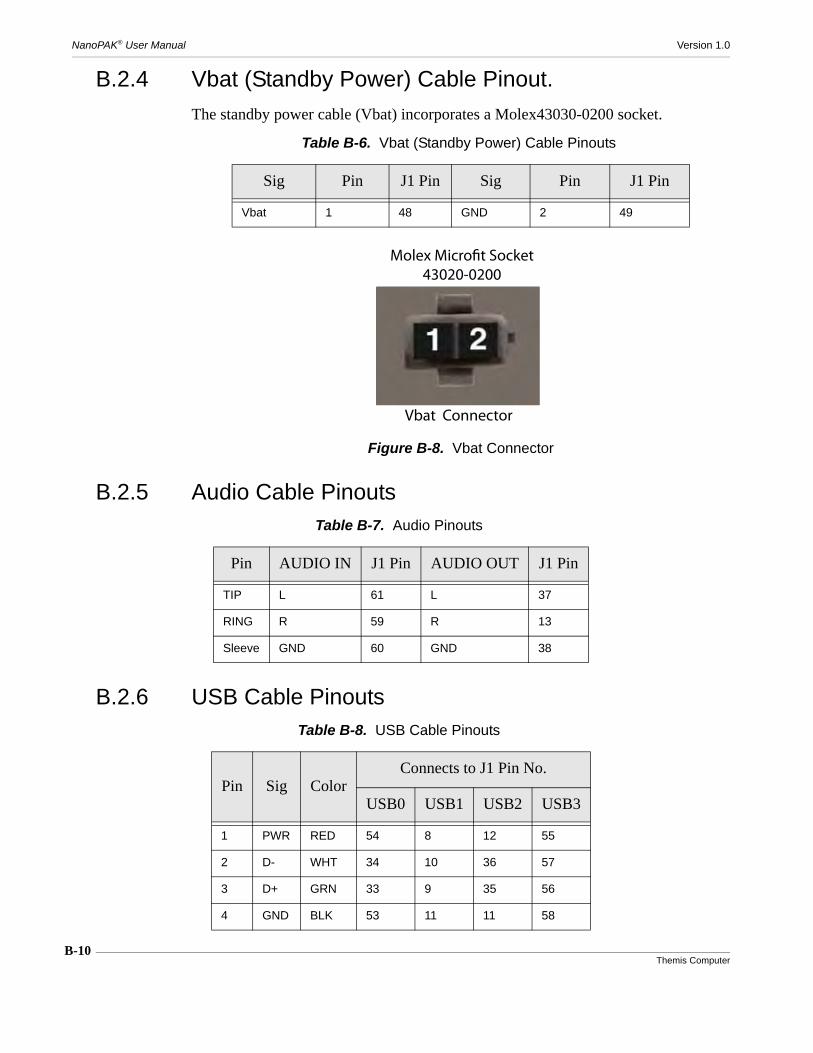
NanoPAK® User Manual Version 1.0
B-10Themis Computer
B.2.4 Vbat (Standby Power) Cable Pinout.
The standby power cable (Vbat) incorporates a Molex43030-0200 socket.
B.2.5 Audio Cable Pinouts
B.2.6 USB Cable Pinouts
Table B-6. Vbat (Standby Power) Cable Pinouts
Sig Pin J1 Pin Sig Pin J1 Pin
Vbat 1 48 GND 2 49
Figure B-8. Vbat Connector
Molex Microfit Socket
43020-0200
Vbat Connector
Table B-7. Audio Pinouts
Pin AUDIO IN J1 Pin AUDIO OUT J1 Pin
TIP L 61 L 37
RING R 59 R 13
Sleeve GND 60 GND 38
Table B-8. USB Cable Pinouts
Pin Sig ColorConnects to J1 Pin No.
USB0 USB1 USB2 USB3
1 PWR RED 54 8 12 55
2 D- WHT 34 10 36 57
3 D+ GRN 33 9 35 56
4 GND BLK 53 11 11 58
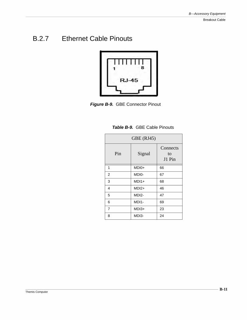
B-11Themis Computer
B—Accessory Equipment
Breakout Cable
B.2.7 Ethernet Cable Pinouts
Figure B-9. GBE Connector Pinout
Table B-9. GBE Cable Pinouts
GBE (RJ45)
Pin SignalConnects
to J1 Pin
1 MDI0+ 66
2 MDI0- 67
3 MDI1+ 68
4 MDI2+ 46
5 MDI2- 47
6 MDI1- 69
7 MDI3+ 23
8 MDI3- 24
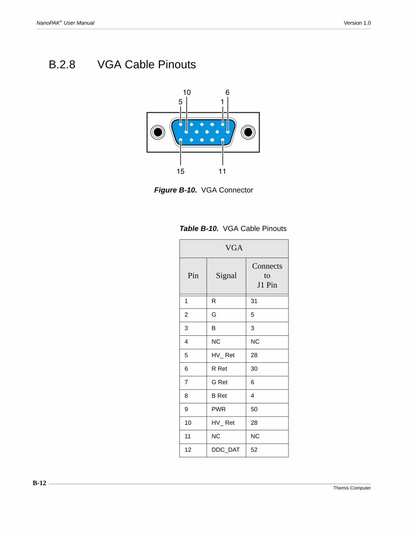
B-12Themis Computer
NanoPAK® User Manual Version 1.0
B.2.8 VGA Cable Pinouts
Figure B-10. VGA Connector
15610
1115
Table B-10. VGA Cable Pinouts
VGA
Pin SignalConnects
to J1 Pin
1 R 31
2 G 5
3 B 3
4 NC NC
5 HV_ Ret 28
6 R Ret 30
7 G Ret 6
8 B Ret 4
9 PWR 50
10 HV_ Ret 28
11 NC NC
12 DDC_DAT 52

B-13Themis Computer
B—Accessory Equipment
Breakout Cable
B.2.9 GPIO Cable Pinouts
All the breakout connectors on the breakout cable are standard connectors for theirtype, except the GPI and GPO connectors, which have a unique pinout. The GPI andGPO connector pinouts are listed in the following table.
13 HSync 29
14 VSync 27
15 DDC_CLK 51
Shield GND 49
Table B-10. VGA Cable Pinouts (Continued)
VGA
Pin SignalConnects
to J1 Pin
Figure B-11. GPO Connector Pins
Molex Microfit Plug
43025-0800
1 2 3 4
5 6 7 8
GPO Connector
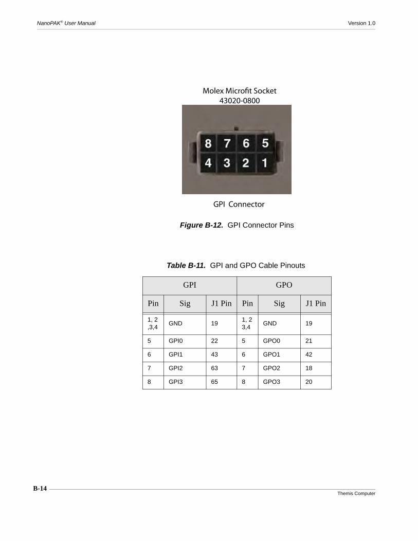
B-14Themis Computer
NanoPAK® User Manual Version 1.0
Figure B-12. GPI Connector Pins
Table B-11. GPI and GPO Cable Pinouts
GPI GPO
Pin Sig J1 Pin Pin Sig J1 Pin
1, 2,3,4
GND 191, 23,4
GND 19
5 GPI0 22 5 GPO0 21
6 GPI1 43 6 GPO1 42
7 GPI2 63 7 GPO2 18
8 GPI3 65 8 GPO3 20
Molex Microfit Socket
43020-0800
GPI Connector
C-1Themis Computer
C
Repackaging Instructions
C.1 Repackaging for Shipment
If it becomes necessary for any reason to return your NanoPAK® unit back to The-mis, it is very important that the original packaging materials be used according tothe repackaging instructions found in this appendix. Themis has qualified all of itsshipping materials to meet the highest of standards and the rigors of today’s shippingmethods, thus insuring total protection of the product during delivery. Failure to useoriginal packaging materials, exactly as described in this appendix may invalidatethe warranty. If the original packaging is no longer serviceable, or no longer avail-able, please contact Themis Customer Support for a new shipping box to send backyour NanoPAK®. When using the original packaging, please remember to place yourNanoPAK® back into the protective bag.
The following instructions assume the original packaging components are still avail-able, and in serviceable condition. If not, please contact Themis for a new shippingbox and packaging components for your NanoPAK®.
Caution: Failure to use the original Themis packaging materials, and failure to fol-low the instructions of this Appendix C, may invalidate the warranty.
Appendix
C-2Themis Computer
NanoPAK® User Manual Version 1.0
C.2 Packaging ComponentsThe packaging components illustrated in this chapter may not exactly match theoriginal packaging components due to the number and configuration of equipmentoriginally shipped. However, they will comprise a packaging box, bottom and topperimeter crush resistant foam pieces, a foam piece with a form-fitting cutout, and aprotective envelope for the equipment.
C.3 Instructions for RepackagingRe-assemble the packaging material about the equipment in accordance with the fol-lowing instructions (see Figure C-1):
1. Inspect the original packaging materials for serviceability.
2. Place the bottom crush-resistant layer into the shipping box, making sure thecorners of the foam fit snugly into the corners of the box.
3. Place the cutout layer into the box.
4. Place the wrapped (in the protective bag) NanoPAK® into the cutout layer.
5. Place the remaining top layer directly on top of the wrapped NanoPAK® unit.
6. Make sure all components of the box are firmly in place, pressing down onthe surface area of the foam to insure proper seating of the material.
7. Seal the top of the box with strong packaging tape, wrapping the tape com-pletely around the box, both lengthwise, and crosswise.
8. Prepare for shipment in accordance with the instructions received from The-mis Computer.
The order of assembly when repackaging the NanoPAK® for shipment as shown in
Note: Please contact Themis if new packaging material, or shipping instructionsare required. You can reach Themis at 1 (510) 252-0870 Mon–Fri, 8am–5pm PST,or by Email to [email protected].
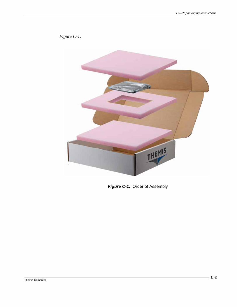
C-3Themis Computer
C—Repackaging Instructions
Figure C-1.
Figure C-1. Order of Assembly

C-4Themis Computer
NanoPAK® User Manual Version 1.0

Index-1Themis Computer
A
Accessory Equipment B-1Appendix C, “Repackaging Instructions” 1-10Applying Power 2-1Audio Cable Pinouts B-10
B
Backup Battery Replacement 2-18BIOS
AMI BIOS Setup UtilityAdvanced Chipset Settings 4-27
North Bridge ChipsetConfiguration 4-28
Boot Display Device 4-29Configure DRAM Timing by
SPD 4-28DRAM Frequency 4-28DVMT / FIXED Memory 4-29DVMT Mode Select 4-29Flat Panel Type 4-29Imitate Graphics Adapter 4-28Internal Graphics Mode
Select 4-29Memory Hole 4-28Spread Spectrum Clock 4-29
South Bridge ChipsetConfiguration 4-30
GbE Controller 4-30GbE LAN Boot 4-30GbE Wake Up from S5 4-30HDA Controller 4-31PCIE High Priority Port 4-31PCIE Port 0 / 1 / 2 / 3 / 4 4-31PCIE Port 0 / 1 / 2 / 3 / 4
IOxAPIC 4-31SLP_S4# Min. Assertion
Width 4-31
SMBUS Controller 4-31USB Functons 4-30USB2.0 controller 4-30
Advanced PCI/PnP Settings 4-21Allocate IRQ to PCI VGA 4-22Clear NVRAM 4-21DMA Channel0 / 1 / 3 / 5 / 6 / 7 4-22IRQ3 / 4 / 5 / 7 / 9 / 10 / 11 4-22OffBoard PCI/ISA IDE Card 4-22Palette Snooping 4-22PCI IDE BusMaster 4-22PCI Latency Timer 4-22Plug & Play O/S 4-22Reserved Memory Size 4-22
Advanced Setup Configuration 4-5ACPI Settings 4-10
Advanced ACPIConfiguration 4-12
ACPI APIC support 4-12ACPI Version Features 4-12AMI OEMB table 4-12Headless Mode 4-12
Chipset ACPI Configuration 4-13
APIC ACPI SCI IRQ 4-13Energy Lake Feature 4-13High Performance Event
Timer 4-13USB Device Wakeup From
S3/S4 4-13General ACPI
Configuration 4-11RePOST Video on S3
Resume 4-11Suspend Mode 4-11
AHCI Configuration 4-14AHCI Port0 / Port1 / Port2 4-14
CPU Configuration 4-6
Index
NanoPAK® User Manual Version 1.0
Index-2Themis Computer
Enhanced C-States 4-7Execute-Disable
Bit Capability 4-6Hyper Threading
Technology 4-6Intel® C-STATE tech 4-7Intel® Speed Step™ 4-6Max CPUID Value Limit 4-6
Event Log Configuration 4-15Clear Event Log 4-15Mark all events as read 4-15View Event Log 4-15
Floppy Configuration 4-9Floppy A/B 4-9
Hardware Health Configuration 4-16ACPI Critical Shutdown
Temp 4-16Hardware Health Function 4-16Temperature and Voltage
Information 4-16IDE Configuration 4-7
ATA(PI) 80Pin CableDetection 4-8
ATA/IDE Configuration 4-7Hard Disk Write Protect 4-8IDE Detect Time Out 4-8Primary / Secondary / Third IDE
Master / Slave 4-8MPS Configuration 4-17
MPS Revision 4-17SMBIOS Configuration 4-18
SMBIOS SMI Support 4-18USB Configuration 4-19
BIOS EHCI Hand-Off 4-19Hotplug USB FDD Support 4-20Legacy USB Support 4-19USB 2.0 Controller Mode 4-19USB Mass Storage Device
Configuration 4-20Emulation Type 4-20USB Mass Storage Reset
Delay 4-20
Boot Settings 4-23Boot Settings Configuration 4-24
AddOn ROM Display Mode 4-24
Bootup Num-Lock 4-24Hit “DEL” Message
Display 4-25Interrupt 19 Capture 4-25PS/2 Mouse Support 4-25Quick Boot 4-24Quiet Boot 4-24Wait for “F1” If Error 4-25
Exit Options 4-32Discard Changes and Exit 4-33Load Fail-Safe Defaults 4-33Load Optimal Defaults 4-33Save Changes and Exit 4-32
Introduction 4-1Starting the BIOS Setup Utility 4-1
Main BIOS Setup 4-3System Overview 4-3
BIOS Information 4-3System Memory Information 4-4System Time/System Date 4-4
Security Setup 4-26Boot Sector Virus Protection 4-26Change supervisor / User
Password 4-26InsydeH2O® BIOS Setup Utility 3-1
Advanced Setup 3-6ACPI Tables/Features Control 3-20AMD PBS Option 3-22Boot Configuration 3-7Chipset Configuration 3-12
Hudson-1 FCH Configuration 3-16
NorthBridge Configuration 3-13APU GPP Features
Configuration 3-15NorthBridge PCIe
Configuration 3-14SouthBridge PCIe
Index
Index-3Themis Computer
Configuration 3-18SouthBridge PCIe Port Features
Configuration 3-19SouthBridge/GPP
Configuration 3-17CPU Related Settings 3-21IDE Configuration 3-9Peripherals Configuration 3-8USB Configuration 3-11Video Configuration 3-10
Boot Configuration 3-26EFI Configuration 3-27Legacy Boot
Device Configuration 3-28Exit Menu 3-29Introduction 3-1Main BIOS Setup 3-4
Language 3-5System Overview 3-4System Time/System Date 3-5
Power Configuration 3-24Advanced CPU Control 3-25
Security Configuration 3-23Starting the BIOS Setup Utility 3-2
Navigating the Utility Screens 3-3Breakout Cable B-3
C
Cable, Breakout, weight B-3Cautions xixChapter Overview xixCOM A 2-9COM B 2-12Comments xxCompliance 1-10Compliance Specifications
Electrical Power 1-10Shock 1-10Vibration 1-10
Configurations 1-5Configure Power 2-2Connector Pinouts, Signals and
Solder Beads A-1Current Protection 2-15
D
Disk Activity LED 2-7
E
Ethernet Activity LED 2-7Ethernet Cable Pinouts B-11Ethernet Link Status LED 2-7Ethernet Port 2-13
F
Front Panel Indicators 2-6
G
General Purpose I/O 2-12General Specifications 1-9GPIO Cable Pinouts B-13
H
HD Audio Interface 2-14
I
Input and Output 2-9Instructions for Repackaging C-2
J
J1 Pinouts and Signals A-1Jumper JP1 A-15Jumper JP6 A-15Jumpers A-15
M
MIL-STD-704 1-10MIL-STD-810F 1-10MIL-STD-901D 1-10
N
NanoPAK® Development Kit B-1Notes xix
NanoPAK® User Manual Version 1.0
Index-4Themis Computer
O
Overview 1-1
P
Packaging and Shipping 1-10Packaging Components C-2Power Button 2-2Power Button Pinout B-9Power Cable Pinouts B-8Power Consumption 2-15Power LED 2-6Provide Adequate Cooling 2-2
R
Repackaging for Shipment C-1Repackaging Instructions C-1
S
Safety Instructions ivElectrostatic Discharge (ESD) iv
Serial Port Pinouts B-7Serial Ports 2-9Sidebars xixSignal Descriptions A-6Sleep Mode Setting 2-4Solder Bead Locations and Settings A-10Solder Beads and Jumpers A-10Specifications 1-9
Dimensions 1-9External Battery Input Current 1-9Input Voltage 1-9Internal Battery Load Current 1-9Power Consumption 1-9Shock 1-9Temperature 1-9Vibration 1-9Weight 1-9
Standby Power/Battery 2-15Storage 2-13System Description 1-2
U
USB Cable Pinouts B-10USB Ports 2-9Useful Tools 2-5
V
Vbat (Standby Power) Cable Pinout. B-10VGA Cable Pinouts B-12Video Port (VGA) 2-13
W
Warnings xixWebsite Information xx
Themis Computer47200 Bayside Parkway
Fremont, CA 94538
Attn: Publications Department
PlaceStampHere
Fold here; tape at top to seal

Reader Comment CardWe welcome your comments and suggestions to help improve the NanoPAK® User Manual. Please take time to let us know what you think about this manual.
•Information provided in the manual was complete.
Agree___ Disagree___ Not Applicable___
•Information was well documented and easy to follow.
Agree___ Disagree___ Not Applicable___
•Information was easily accessible.
Agree___ Disagree___ Not Applicable___
•The manual was useful.
Agree___ Disagree___ Not Applicable___
• Please write down any comments you may have about this manual, including how it can be improved:
___________________________________________________________
___________________________________________________________
___________________________________________________________
___________________________________________________________
___________________________________________________________
___________________________________________________________
___________________________________________________________
___________________________________________________________
___________________________________________________________
Name: _____________________________________________________
Title: _____________________________________________________
Company: _____________________________________________________
Address: _____________________________________________________
Related Documents


