EN User Manual Sliding gate with drives HMD230 HGD230 IGD230 Version 1.6, May 2016 Translation of the original User Manual Please read this original user manual before using this sliding gate for the first time! Act in accordance with the manual and keep it in a safe place for later use or for the following owner.

Welcome message from author
This document is posted to help you gain knowledge. Please leave a comment to let me know what you think about it! Share it to your friends and learn new things together.
Transcript

EN
User Manual Sliding gate with drives
HMD230 HGD230 IGD230
Version 1.6, May 2016 Translation of the original User Manual
Please read this original user manual before using this sliding gate for the first time! Act in accordance with the manual and keep it in a safe place for later use or for the following owner.

www.heras.com
English 2

www.heras.com
English 3
CONTENTS
FOREWORD ............................................................................................................................. 6
1 PREFACE ............................................................................................................................. 7
1.1 MANUFACTURER / SUPPLIER ................................................................................... 7 1.2 SERVICE / MAINTENANCE ......................................................................................... 7 1.3 DEFINITIONS: USER / OPERATOR / ENGINEER ....................................................... 7 1.4 PRESCRIBED USE / APPLICATION ........................................................................... 7 1.5 CONFORMITY WITH EUROPEAN DIRECTIVES ........................................................ 8 1.6 DELIVERY ................................................................................................................... 8 1.7 GENERAL INFORMATION REGARDING THE ELECTRICAL CONNECTIONS ........... 8 1.8 DELIVERY OF DRIVE UNIT ......................................................................................... 9 1.9 HMD230 / HGD230 ...................................................................................................... 9 1.10 IGD230 ................................................................................................................... 10
2 SAFETY ........................................................................................................................... 10
2.1 EXPLANATION OF THE SYMBOLS .......................................................................... 10 2.2 SAFETY DISTANCES ................................................................................................ 10 2.3 GENERAL SAFETY INSTRUCTIONS ........................................................................ 11 2.4 SAFETY PROVISIONS EMPLOYED ......................................................................... 11 2.5 INTENDED USE ........................................................................................................ 12 2.6 SAFETY DURING USE .............................................................................................. 12 2.7 SAFETY DURING INSTALLATION, MAINTENANCE AND DISASSEMBLY ............... 13
3 DESCRIPTION ................................................................................................................. 14
3.1 DELTA ....................................................................................................................... 14 3.2 UGATE ...................................................................................................................... 15 3.3 IGATE ........................................................................................................................ 15 3.4 SHB ........................................................................................................................... 16 3.5 DRIVE UNIT............................................................................................................... 16
Drive unit variants ............................................................................................... 16 3.5.1 HMD230 and HGD230 profiles ........................................................................... 17 3.5.2
3.6 SAFETY EDGES ....................................................................................................... 18 3.7 PHOTOCELLS ........................................................................................................... 18 3.8 ACCESSOIRES ......................................................................................................... 18
Loop detection (optional) .................................................................................... 18 3.8.1 Traffic light (optional) .......................................................................................... 18 3.8.2 Flash light (optional*) .......................................................................................... 18 3.8.3 Remote control (optional) .................................................................................... 19 3.8.4 Lighting (optional*) .............................................................................................. 19 3.8.5 Led lighting in top rail (optional) .......................................................................... 19 3.8.6
4 OPERATION .................................................................................................................... 20
4.1 OPENING/CLOSING SLIDING GATE - NORMAL USE .............................................. 20 4.2 OPEN /CLOSE SLIDING GATE - EMERGENCY USE ................................................ 20
Opening the cover .............................................................................................. 20 4.2.1

www.heras.com
English 4
Closing the cover ................................................................................................ 20 4.2.24.3 OPEN / CLOSE IN CASE OF EMERGENCY .............................................................. 21 4.4 OPERATING MODES ................................................................................................ 21
Hold-to-run-control .............................................................................................. 21 4.4.1 Automatic mode .................................................................................................. 22 4.4.2 Emergency operation .......................................................................................... 22 4.4.3
4.5 AUTOMATICALLY CHANGING OPERATING MODES .............................................. 23
5 CONTROL UNIT AND DISPLAY READINGS .................................................................. 24
5.1 TOTAL VIEW OF HMD230 DRIVE UNIT .................................................................... 24 5.2 TOTAL VIEW OF HGD230/IGD230 DRIVE UNIT ....................................................... 24 5.3 VIEW OF CONTROL UNIT ......................................................................................... 25 5.4 TWIST AND SELECTOR SWITCH ............................................................................. 26 5.5 LCD SCREEN ............................................................................................................ 26 5.6 DISPLAY OF OPERATING MODES .......................................................................... 27 5.7 DATE AND TIME DISPLAY ........................................................................................ 28 5.8 SELECTING THE MENU SYSTEM ............................................................................ 28 5.9 MENU DISPLAY INSTRUCTIONS ............................................................................. 28 5.10 MENU STRUCTURE AND TEXTS THAT ARE DISPLAYED ................................... 29 5.11 BACKPLANE .......................................................................................................... 29
6 PARAMETER SETTINGS ................................................................................................ 30
6.1 MENU 1 – IDENTIFICATION ...................................................................................... 30 Menu 1.1: Master version.................................................................................... 30 6.1.1 Menu 1.2: Gate profile ........................................................................................ 30 6.1.2 Menu 1.3: Serial number ..................................................................................... 31 6.1.3
6.2 MENU 2 - SERVICE MENU ........................................................................................ 32 Menu 2.1: Password entry .................................................................................. 32 6.2.1
6.3 MENU 3 - DIAGNOSIS ............................................................................................... 32 Menu 3.1: Gate status ......................................................................................... 32 6.3.1 Menu 3.2: Sensor Status .................................................................................... 34 6.3.2
6.4 MENU 4 - SETTINGS ................................................................................................. 36 Menu 4.1: Timer settings .................................................................................... 36 6.4.1
6.4.1.1 Menu 4.1.1: Set lighting (coming home - leaving home) .................................. 36 6.4.1.2 Menu 4.1.2: Keep open timer .......................................................................... 37 6.4.1.3 Menu 4.1.3: Keep Part OPEN timer ................................................................. 38
Menu 4.2: End positions .................................................................................... 39 6.4.26.4.2.1 Menu 4.2.1: Closed position for installing ........................................................ 39
Marker plate ........................................................................................................ 41 6.4.36.5 MENU 5 - CLOCK/CALENDAR .................................................................................. 41
Menu 5.1: Clock display ...................................................................................... 42 6.5.1 Menu 5.2: Setting date/time ................................................................................ 42 6.5.2 Calendar functions of the motor drive ................................................................. 44 6.5.3 Menu 5.3: Activating the calendar ....................................................................... 45 6.5.4 Menu 5.4: Displaying the weekly calendar .......................................................... 46 6.5.5 Menu 5.5: Changing the weekly calendar ........................................................... 47 6.5.6
6.5.6.1 Menu 5.5.1: Week day setting ......................................................................... 47 6.5.6.2 Menu 5.5.1: Copying a day in the weekly calendar .......................................... 48

www.heras.com
English 5
6.5.6.3 Menu 5.5.1: Deleting individual entries ............................................................ 49 6.5.6.4 Menu 5.5.1: Deleting a week day .................................................................... 50 6.5.6.5 Menu 5.5.2: Deleting the weekly calendar ....................................................... 52
Menu 5.6: Displaying the yearly calendar ............................................................ 52 6.5.7 Menu 5.7: Changing the yearly calendar ............................................................. 53 6.5.8
6.5.8.1 Menu 5.7.1: Set day ........................................................................................ 53 6.5.8.2 Menu 5.7.1: Copying a day in the yearly calendar ........................................... 55 6.5.8.3 Menu 5.7.1: Deleting individual entries ............................................................ 57 6.5.8.4 Menu 5.7.1: Deleting a day .............................................................................. 58 6.5.8.5 Menu 5.7.2: Deleting the entire yearly calendar ............................................... 59
6.6 MENU 6 - RF REMOTE CONTROL ............................................................................ 59 Menu 6.1: Displaying the number of hand transmitters ....................................... 60 6.6.1 Menu 6.2: Teaching hand transmitters ................................................................ 61 6.6.2 Menu 6.3-6.6: Programming hand transmitter buttons ........................................ 62 6.6.3
6.6.3.1 Menu 6.3: Programming hand transmitter button OPEN .................................. 62 6.6.3.2 Menu 6.4: Programming hand transmitter button CLOSE ................................ 63 6.6.3.3 Menu 6.5: Programming hand transmitter button PART OPEN ....................... 63 6.6.3.4 Menu 6.6: Programming hand transmitter button TOGGLE ............................. 64
Menu 6.7: Deleting transmitters from the memory ............................................... 65 6.6.4 Menu 6.8: Deleting hand transmitter function ...................................................... 67 6.6.5 Menu 6.9: Deleting all transmitters from the memory .......................................... 68 6.6.6
6.7 LED LIGHTING OPERATION ........................................................................................... 68
7 FAULTS ........................................................................................................................... 69
7.1 DEFECTIVE PHOTOCELL OR SAFETY EDGE ......................................................... 69 7.2 DISENGAGING THE MOTOR .................................................................................... 69 7.3 SENGAGING THE MOTOR ....................................................................................... 70 7.4 AUTOMATIC DISENGAGEMENT .............................................................................. 70
8 EMERGENCY STOP ........................................................................................................ 70
9 MAINTENANCE INSTRUCTIONS .................................................................................... 71
9.1 GATE MAINTENANCE .............................................................................................. 71 9.2 DRIVE UNIT MAINTENANCE .................................................................................... 71 9.3 CLEANING ................................................................................................................ 71
10 DECOMMISSIONING AND REMOVAL ........................................................................ 72
11 SPARE PARTS ............................................................................................................. 72
12 TECHNICAL DATA ....................................................................................................... 73
12.1 SLIDING GATE DESCRIPTION ............................................................................. 73 12.2 DRIVE DESCRIPTION ........................................................................................... 73
APPENDIX A: CONFIGURATION SAFETY EDGES .............................................................. 74
APPENDIX B: DECLARATIONS DOP / DOC ......................................................................... 75
APPENDIX C: ELECTRIC DIAGRAM HMD230 / HGD230 ..................................................... 77
APPENDIX D: ELECTRIC DIAGRAM IGD230 ....................................................................... 91

www.heras.com
English 6
FOREWORD
This manual enables you to operate and maintain the sliding gate correctly. It also describes which drive variants are possible and for which sliding gates. Possible options are briefly described. The Operation chapter explains the control unit. Among other things, it describes how you can change various settings. The Maintenance chapter is extremely important to ensure that you can continue to operate your gate problem free in the long term. The major change made to Version 1.4 is the addition of our HGD drive. The sequence of the chapters has changed and we have placed more emphasis on safety. The Orion sliding gate is no longer included in this manual. Version 1.5: Illustration paragraph 2.7 + Declaration of conformity (DoC) added in appendix B. Appendix A modified. Please read this user manual carefully before using the sliding gate. Store the manual in a safe place to be able to refer to it later if required. This description is intended for the operator of the gate. The installer uses a separate manual to assemble and install the gate. The installer uses an installation scheme for the drive concerned and works according to the applicable standards. In the event of a fault, you should contact a Heras certified technician.

www.heras.com
English 7
1 PREFACE 1.1 MANUFACTURER / SUPPLIER Manufacturer: Heras B.V. Hekdam 1, 5688 JE Oirschot Netherlands Tel.: +31(0)499-551225 www.heras.com Technical Construction File: Heras B.V. manager, R&D Department 1.2 SERVICE / MAINTENANCE In the event of problems, failures or questions you can contact: Heras Service Tel. 0900 202 0499* Fax 0900 202 4550
* local rate Only available from the Netherlands. If you are located elsewhere, please contact your dealer for assistance. 1.3 DEFINITIONS: USER / OPERATOR / ENGINEER User: Anyone using the gate. Operator: A user who is familiar with all safety aspects dealt with in this manual. Operators
are not allowed to carry out any installation work on the gate unless explicitly specified.
Engineer: The engineer is a Heras fitter (or an engineer employed by the customer who
has been given explicit permission in writing from Heras) who is qualified to perform technical interventions on the gate.
1.4 PRESCRIBED USE / APPLICATION Only the correct installation and maintenance by an authorised/qualified company or person in agreement with the user manual, logbook, checklists and maintenance lists can ensure the safe operation of the system. A qualified person is, according to EN 12635, a person who has the required training, qualified knowledge and practical experience required to install, test and maintain a sliding gate system correctly and safely.

www.heras.com
English 8
1.5 CONFORMITY WITH EUROPEAN DIRECTIVES The installation complies with the following EU Directives/ regulations: 2006/42/ EC Machine Directive 2004/108 EC EMC Directive (electromagnetic compatibility) 305/2011 EC Construction Product Regulation
The design and production has been executed compliant with the applicable product standard EN 13241-1 and the underlying standards EN 12604, EN 12605, EN 12453, EN 12445, EN 12978 and 12635. A Declaration of Performance (DoP) and Declaration of Conformity (DoC) are obligatory for this product. The DoP and DoC are included in Appendix B. The CE mark is located on the rear of the bottom rail of the gate. 1.6 DELIVERY The sliding gate and the gate drive and control unit must be installed, connected, set up and tuned by a fitter or an engineer who also connects and programs any accessories. The gate control unit is adjusted to the options/accessories agreed with the user. The relevant options are laid down during hand-over. Of course, you can add optional/accessories afterwards. Contact your supplier for this. Gates are always delivered fully tested. 1.7 GENERAL INFORMATION REGARDING THE ELECTRICAL CONNECTIONS Electrical connections must be made compliant with the supplied wiring diagram. It is important that the system is correctly earthed (Protective earthing in accordance with DIN VDE). Earth the ring terminal with a 16 mm2 cable to an earth electrode. Because EMC-related suppressors can leak current to the earth cable, it is advisable that you do not protect the control unit with a Residual Current Device. When switching on the system, a high starting current can be generated due to the charging of the intermediate circuit. Ensure that the system is effectively protected, for instance by a 16A B circuit breaker.
Ensure that the feeder cables are not carrying power during commissioning.

www.heras.com
English 9
1.8 DELIVERY OF DRIVE UNIT
Due to the weight of the drive unit (approximately 26 kg), a forklift or pallet truck must be used for its installation and replacement.
After installation and commissioning, by a Heras technician or a technician trained by Heras, the cover of the HMD230/HGD230 and IGD drive unit must be locked with a key. This key is then handed over to the customer. This is done to prevent unauthorised access. 1.9 HMD230 / HGD230 The HMD230 / HGD230 are delivered as a complete drive and control unit, including gear wheel module 6. By default, the half profile cylinder (according to DIN 18252) is not included for the Netherlands.
Illustration 1: HGD230 cover, cabinet and gear wheel
Illustration 2: HGD230 cover, cabinet and gear wheel

www.heras.com
English 10
1.10 IGD230 The IGD230 is delivered as a complete drive and control unit, including gear wheel module 6. The drive is only delivered together with the iGate. By default, the half profile cylinder (according to DIN 18252) is not included for the Netherlands.
Illustration 3: IGD230 cover, cabinet and gear wheel
2 SAFETY
2.1 EXPLANATION OF THE SYMBOLS
Caution: To prevent personal injury, you must observe the safety instructions below.
Note: To prevent material damage, you must observe the safety instructions below.
Information: This is followed by further information or by a reference to other documents.
Warning: Risk of limbs getting crushed
Warning: Risk of injury to hands by gear wheels
2.2 SAFETY DISTANCES Safety distances apply for the area into which the gate slides in accordance with EN 12445 4.1.1.1 for electrically driven sliding gates.

www.heras.com
English 11
2.3 GENERAL SAFETY INSTRUCTIONS
The operator must read the entire user manual before the gate is used for the first time. The instructions stated in the user manual must be observed and complied with. All other forms of use can cause unexpected hazards and are forbidden.
It is forbidden to apply the drive unit to gates other than those stated in this manual, without Heras' permission.
Applying a third-party drive unit and/or safety edge may affect safety and will invalidate the CE mark.
The gate must only be put into use if all safety facilities are in place and connected, and work properly.
All faults which might present a source of danger to the user or to third persons must be eliminated immediately.
All warnings and safety notices on the equipment must be in place and clearly legible at all times.
Closing the gate infill openings in any way, such as by means of banners, advertising signs etc, is not allowed as this may negatively affect the safe operation of the gate.
All alterations or extensions to the gate must be carried out by qualified personnel using parts which the manufacturer has defined as suitable for such alterations or extensions. Any failure to comply with these instructions will be considered as non-compliant behavior and will invalidate the manufacturer's guarantee, as a result of which the risk entirely transfers to the user.
For a double sliding gate, it is strictly forbidden to remove the central slam support (mounted on the floor in the opening). This is important for the stability of the gate when closed.
Improper usage or servicing or ignoring the operating instructions can be a source of danger for persons, and/or result in material damage.
If the meaning of any part of these installation and operating instructions is not clear, then please contact your supplier before you use the equipment.
2.4 SAFETY PROVISIONS EMPLOYED To protect people and goods from injury or damage, the gate is fitted with safety
provisions including safety edges and/or photocells. These serve as emergency provisions that immediately stop and reverse the movement of the gate. It is forbidden to use these provisions to stop the gate normally.
For a gate with hold-to-run control, the above-mentioned safety provisions are not necessary and will therefore not be standard provisions. With this type of operation, the gate stops immediately as soon as the switch is released.

www.heras.com
English 12
2.5 INTENDED USE The gate is intended to control access to a specific plot, premises or site. The gate is intended for both industrial and private use. The gate drive and control unit is adjusted to the options agreed with the user. The relevant options are laid down during hand-over.
Carefully read this user manual before operating the gate. You must always be familiar with the operating mode the gate is in.
2.6 SAFETY DURING USE
Children or people with a disability must not operate the gate. Parents must supervise their children to prevent them playing with the gate.
PARENTS ARE RESPONSIBLE FOR THEIR CHILDREN
Keep a safe distance from the moving gate. Warning icons to this effect have been installed in various locations.
Only pass through the gate when it is completely open. The gate must not be operated in windy conditions, wind force ≥9 Beaufort. The gate
leaf can swing in a way that can result in damage to the construction. The safety edges serve as emergency facilities to immediately stop and reverse the
gate movement. Using them as a regular gate stop feature is not allowed. Since the head stiles of the gate have safety edges that cannot cover their full height, there is still some risk of people getting trapped by the gate here.
When hold-to-run-control is employed, the gate must only be operated if it can be seen completely, directly and in real-time. Operation must be via a permanently installed operating device, for instance a key switch or push button. This operating device must be located in such a way that the operator's position is safe. The gate must stop immediately when the button or key is released. Other operating devices are not allowed.
The gate must be able to move freely without there being obstacles in the gate opening passage or anywhere else on the moving trajectory of the gate.
Do not stick any objects through, over or under the gate which might block the gate. The gate running surface must always be free from snow, ice or dirt that might affect
its sliding behaviour. In the event of frost, check this before commissioning the gate. If the running surface is blocked, the gate will not move at all or will not complete its movement. An irregular running surface may cause damage to the drive and/or road wheels.
In certain circumstances, the sun can temporarily distort the gate. When closing the gate, the leaf is guided to its neutral position. When opening the gate, the leaf will move around somewhat. This has no adverse consequences for the construction.
Climbing the gate is strictly forbidden as people climbing the gate could be hurt if the gate is started unexpectedly.
Do not place any obstacles in the opening. Always lock the drive unit cabinet during use.

www.heras.com
English 13
2.7 SAFETY DURING INSTALLATION, MAINTENANCE AND DISASSEMBLY When work is carried out or while cleaning the gate, the power supply to the system
must be switched off and it must be ensured that it cannot be switched on unexpectedly.
Use the necessary personal safety equipment. The gate is driven by means of a gear wheel. This is located under the beam and it
is partly screened off by the drive unit cabinet. Beware of moving parts when carrying out maintenance under the gate at the drive unit cabinet.
To move the gate manually, first switch the automatic fuse in the drive unit cabinet to “off” and make sure it cannot be switched on again (e.g. by locking the cabinet).
The EN 13241-1, EN 12453 and EN 12445 standards must be taken into consideration during installation. To achieve a good safety level, both the above standards and the national regulations must be taken into account in non-EC countries.
The Delta, uGate and iGate have highly tensioned cables fitted in the bottom rail. If these cables are damaged, they can snap with great force. This can lead to serious injury. Therefore, it is prohibited to drill into or grind these rails.
!! Only people trained by Heras are allowed to disassemble the bottom rail.
If the gate is damaged, always contact the supplier for an inspection.
Illustration 4: Warning sticker bottom rail
www.heras.com
English 14
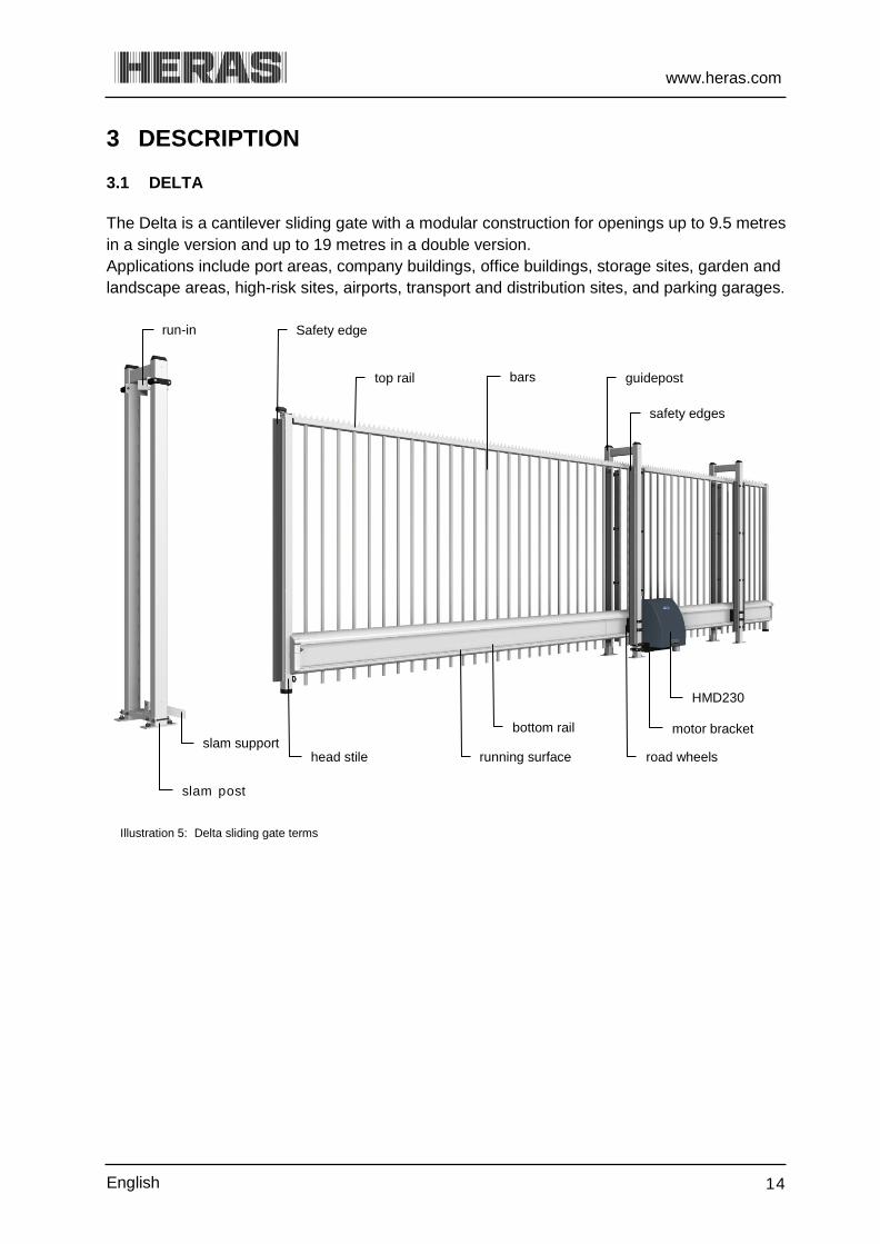
3 DESCRIPTION 3.1 DELTA The Delta is a cantilever sliding gate with a modular construction for openings up to 9.5 metres in a single version and up to 19 metres in a double version. Applications include port areas, company buildings, office buildings, storage sites, garden and landscape areas, high-risk sites, airports, transport and distribution sites, and parking garages.
Illustration 5: Delta sliding gate terms
slam post
slam support
run-in Safety edge
head stile
bottom rail
HMD230
motor bracket
road wheels running surface
safety edges
guidepost top rail bars

www.heras.com
English 15
3.2 UGATE The uGate is a cantilever sliding gate with a modular structure for openings up to 12 metres in a single version and up to 24 metres in a double version.
Applications include port areas, company buildings, office buildings, storage sites, garden and landscape areas, high-risk sites, airports, transport and distribution sites, and parking garages.
Illustration 6: Begrippen schuifpoort uGate
3.3 IGATE The iGate is a cantilever sliding gate for openings up to 9 metres in a single version. The filling consists of perforated sheeting.
Applications include locations where design also plays an important role.
Illustration 7: iGate sliding gate terms
bottom rail
HGD230 road wheels
slam post
running surface
head stile + safety edge
safety edges
bars guidepost
bottom rail
IGD
road wheels running surface
head stile
slam support slam column
safety edges
top rail + LED lighting
perforated plating guide column
flash light

www.heras.com
English 16
3.4 SHB The SHB is a sliding gate on a rail for openings up to 13 metres in a single version and up to 26 metres in a double version.
Applications include harbour areas, company buildings, storage sites, high-risk sites, airports, and transport and distribution sites.
Illustration 8: SHB sliding gate terms
3.5 DRIVE UNIT
Drive unit variants 3.5.1 The following sliding gate/drive unit combinations are possible:
Drive unit type Sliding gate type
HMD230S HMD230A HGD230S HGD230A IGD230P IGD230E
DELTA ■ ■ uGATE ■ ■ iGATE ■ ■ SHB ■ ■
Drive unit type
Gate speed
HMD230S HMD230A HGD230S HGD230A IGD230P IGD230E
0,25 m/s ■ ■ ■ ■ 0,5 m/s ■ ■ ■ S = Standard, A = Advanced, P = Premium, E = Excellent
HMD230 slam post
safety edge
bottom rail
guidepost bars

www.heras.com
English 17
See the chapter 13 "TECHNICAL DATA" for further information.
The motor of the HMD230/IGD has a pulse generator enabling the motor control to determine the gate position. Limit switches are not necessary anymore.
HMD230 and HGD230 profiles 3.5.2 The HMD230 and HGD230 are delivered with a pre-programmed profile (does not apply to the Netherlands). This profile cannot be changed by the user.
PROFILE 1 PROFILE 2 PROFILE 3 PROFILE 4 Hold-to-run
mode Pulse mode Pulse mode +
weekly calendar
Pulse mode + yearly calendar
Choice of language (3 languages)
■ ■ ■ ■
Log function ■ ■ ■ ■ Setting date/time
■ ■ ■ ■
Inputs 1-2-3 Open-stop-closed ■ ■ ■
Input 4 Toggle Open-Closed ■ ■ ■
Input 5 Part open ■ ■ ■
Input 6 Emergency stop ■ ■ ■ ■
Inputs 7-8 Dead man's Open-Closed ■ Output 1
Light/Flash light control with pre-warn ■ ■ ■ ■
Outputs 2-3 Gate Open-Closed messages
■ ■ ■ ■
Output 4 "Service" message ■ ■ ■ ■
Output 5 Switch external heating ■ ■ ■ ■ Hand transmitter receiver
+ 1x hand transmitter ■ ■ ■
Weekly calendar
■
Yearly calendar ■ HMD230 Standard
HMD230S1 (0.25 m/sec)
HMD230S2 (0.25 m/sec)
HMD230S3 (0.25 m/sec)
HMD230S4 (0.25 m/sec)
HMD230 Advanced
Not available HMD230A2 (0.5 m/sec)
HMD230A3 (0.5 m/sec)
HMD230A4 (0.5 m/sec)
iGATE Premium
(0.25 m/sec) Excellent
(0.5 m/sec) Excellent
(0.5 m/sec) Excellent
(0.5 m/sec)

www.heras.com
English 18
3.6 SAFETY EDGES Electrically driven Heras gates are protected by safety edges. The type of device and the speed of movement depend on the motor control unit used. If the safety device touches an obstacle, the gate will immediately stop and reverse. Dependent on the device, the gate will restart. The safety edges have been fitted to the stationary and/or moving part or parts of the gate. They are not required for hold-to-run-control. These strips serve as safety components. The number of safety edges depends on the situation. See appendix A " Configuration safety edges " Before the gate is moved, the control system checks the status of the safety edges. If one of the safety edges is faulty, the gate can only be opened and closed in hold-to-run-mode. In that case, consult a qualified engineer.
See the chapter 1.2 “SERVICE /MAINTENANCE”
3.7 PHOTOCELLS Photocells detect whether there are obstacles in the path taken by the gate. If an obstacle is detected, the gate will stop immediately and slide open to its original starting point (OPEN or PARTIALLY OPEN). Dependent on the device, the gate will restart. The photocell is only active when the gate is being closed. Gates can be fitted with multiple photocells. 3.8 ACCESSOIRES
Loop detection (optional) 3.8.1
A detection loop is an induction loop embedded in the road surface that, with the assistance of electronics, can detect a vehicle. When the loop detects a vehicle, the gate will open and/or stay open. Detection loops do not detect people.
Traffic light (optional) 3.8.2 Red/green signal lights that indicate the open/closed position statuses. People are only allowed to pass through the gate opening when the green light is on.
Flash light (optional*) 3.8.3 A flashing beacon to ensure extra attention before and while the gate is opening/closing.
A technician can program the switching time. * In some countries, a flashing light is obligatory.
www.heras.com
English 19
Remote control (optional) 3.8.4 Remote control to open, stop and close the gate.
See the chapter “Menu 6 REMOTE CONTROL” Ensure that the remote control cannot come within reach of children and that it can only be accessed by authorised people. Only use the remote control in the vicinity of the gate, so that you can see the entire gate.
Note that the button of the remote control can be pressed accidentally, for instance, when it is in a pocket and this can lead to undesired gate movements.
Lighting (optional*) 3.8.5 Two kinds of lighting can be connected to the HMD230. Passage lighting to enhance the visibility of the passage opening. It can be lit before
and/or while the gate is opening/closing. Outdoor lighting to illuminate the grounds. This is activated as soon as the gate is
operated and it is switched off automatically after a certain pre-set time. * In some countries, lighting is obligatory.
Led lighting in top rail (optional) 3.8.6
The iGate can optionally be fitted with LED lighting in the top rail. This lighting serves as atmospheric lighting if the gate is closed. The lighting is only on when the gate is closed and the dusk to dawn lighting is active.
See the chapter “LED LIGHTING OPERATION” Accessories must be installed and programmed by an engineer. This requires entering the right password.

www.heras.com
English 20
4 OPERATION 4.1 OPENING/CLOSING SLIDING GATE - NORMAL USE The gate can be operated using pulse operation, for instance via a button or key switch. The location of the operating device depends on the customer's choice or the operating mode.
OPEN: Press the “Open” button. The gate slides open to the next end position. This can be completely or partially open (if the “Partially open” function has been programmed).
CLOSE: Press the "Close" button. The gate closes completely.
STOP: Press the "Stop" button. The gate will stop immediately, irrespective of its direction of travel. To restart the gate press “Open” or "Close".
4.2 OPEN /CLOSE SLIDING GATE - EMERGENCY USE In an emergency, the gate can also be operated from the drive unit. To do this the cover of the motor unit must be opened.
Opening the cover 4.2.1 Open the lock. Turn the lever through a quarter rotation in a clockwise
direction. Now rotate the cover through approx. 90º so that it can
serve as a rain cover. Lift the cover away in a vertical movement .
Illustration 9: opening the cover
Closing the cover 4.2.2 Lower the tabs of the cover into the slot in the drive unit
cabinet. Screw the cover into place to close it. Make sure that the
sides of the cover properly fit over the drive unit cabinet Close the lever and the lock.
Illustration 10: closing the cover* * The illustration shows the HMD230. The same principle applies to the HGD230 and 230IGD.
www.heras.com
English 21
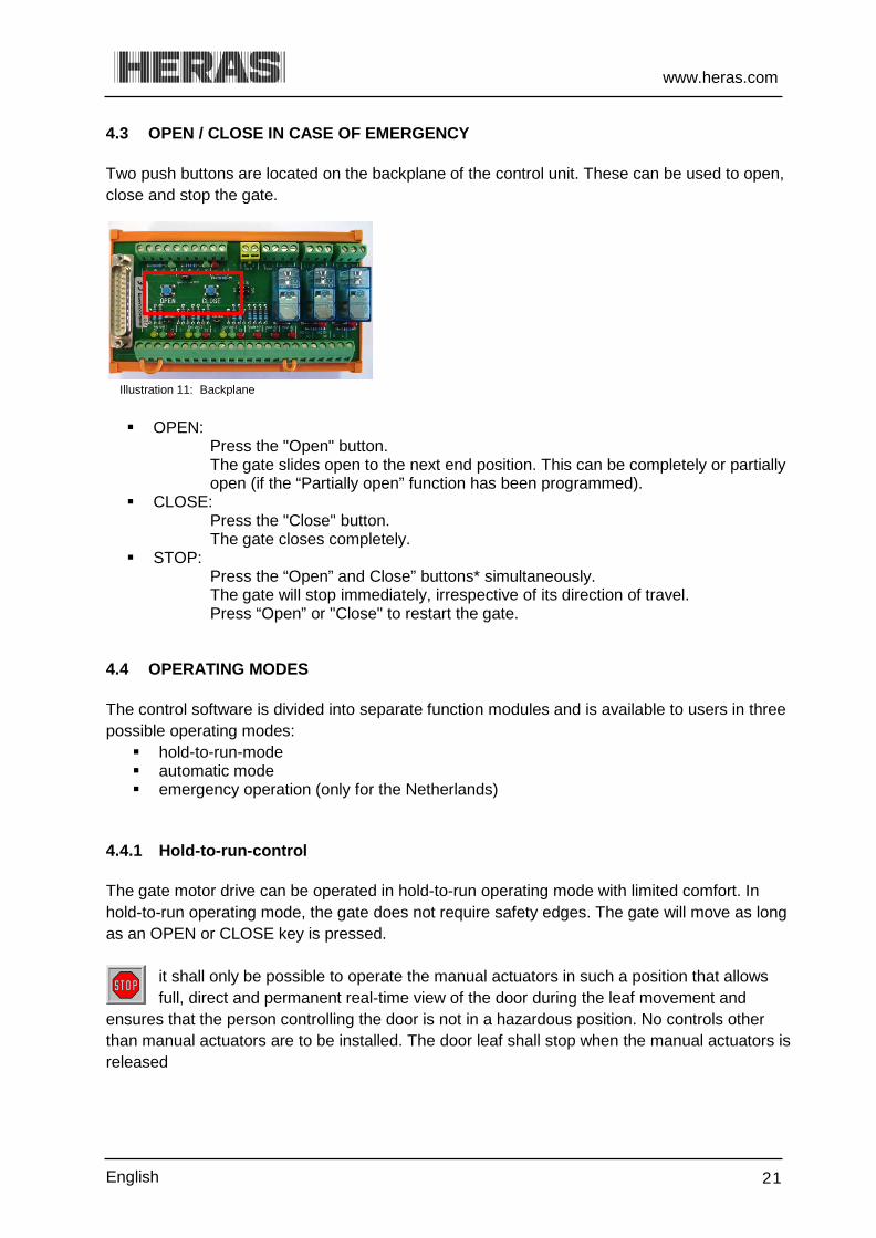
4.3 OPEN / CLOSE IN CASE OF EMERGENCY Two push buttons are located on the backplane of the control unit. These can be used to open, close and stop the gate.
Illustration 11: Backplane
OPEN:
Press the "Open" button. The gate slides open to the next end position. This can be completely or partially open (if the “Partially open” function has been programmed).
CLOSE: Press the "Close" button. The gate closes completely.
STOP: Press the “Open” and Close” buttons* simultaneously. The gate will stop immediately, irrespective of its direction of travel. Press “Open” or "Close" to restart the gate.
4.4 OPERATING MODES The control software is divided into separate function modules and is available to users in three possible operating modes: hold-to-run-mode automatic mode emergency operation (only for the Netherlands)
Hold-to-run-control 4.4.1 The gate motor drive can be operated in hold-to-run operating mode with limited comfort. In hold-to-run operating mode, the gate does not require safety edges. The gate will move as long as an OPEN or CLOSE key is pressed.
it shall only be possible to operate the manual actuators in such a position that allows full, direct and permanent real-time view of the door during the leaf movement and
ensures that the person controlling the door is not in a hazardous position. No controls other than manual actuators are to be installed. The door leaf shall stop when the manual actuators is released

www.heras.com
English 22
Automatic mode 4.4.2 If the safety facilities have been installed completely, the motor drive will usually work in this automatic mode. The user can only use all motor drive functions in automatic mode. Total safety of the gate is guaranteed here by the activated safety facilities. Opening or closing the gate can be initiated in automatic mode by means of the backplane and: two command keys (OPEN, CLOSE) one impulse input with toggle function (OPEN, STOP, CLOSE, STOP) 3x3 impulse inputs for OPEN, STOP and CLOSE commands 1 impulse input with PART OPEN function
Illustration 12: Backplane
Every movement command causes the full action that has been selected to be performed (open gate, close gate etc.). Every action is stopped immediately by a stop command or a signal from the safety facilities. Activating the safety edge causes the gate to immediately move in the opposite direction. If a photocell is interrupted while the gate is closing, this will cause the gate to be opened as far as the point where the closing movement started (OPEN or PARTLY OPEN). A movement command for the opposite direction will gradually decelerate the gate and then cause it to move in opposite direction. Automatic mode if the gate has not been installed fully yet:
If the gate has not been fully installed yet, or if motor drive programming has not been completed yet, the motor drive will work in a special safety mode (e.g.: the end positions
of the gate have not been defined yet). The gate will then only run at dead man's mode speed. Only after the OPEN and CLOSED end positions have been set and after a measuring run at dead man's mode speed has been performed, will the system switch over to the automatic mode speed (depending on the type, HMD230/IGD, this will be 0.25 m/s or 0.5 m/s). If the power supply to the drive has been interrupted, the gate will also only run at dead man's mode speed until the first time when an end position has been reached.
Emergency operation 4.4.3 The gate motor drive can switch over automatically from automatic mode to emergency operation. This automatic switch-over can only take place after a "Function emergency situation" input signal which is generated by a fire emergency room. Only the one movement (OPEN or CLOSED, depending on programming) that is requested will be performed at dead man's mode speed in this operating mode. The safety facilities are also activated during this

www.heras.com
English 23
movement. The movement can be interrupted by pressing and holding the STOP key or by a safety device being triggered. When this interruption no longer applies, the gate will immediately continue to move. At the end of the emergency movement and after the signal ("Function emergency situation") has been reset, the software of the motor drive will initiate a restart to enable safe switch-over to automatic mode. Any static active OPEN or PARTLY OPEN signals are ignored by the motor drive in this operating mode. Just as the command triggered by an OPEN or CLOSE command key being pressed cannot be performed when a program is started, a static active "Emergency situation" input signal will also not be carried out when switching on the motor drive. 4.5 AUTOMATICALLY CHANGING OPERATING MODES The gate motor drive can switch over from automatic mode to emergency operation if it has been programmed to allow this and the HMD230/IGD recognizes a corresponding "emergency situation" signal from a fire emergency room. This operating mode will then be performed until the motor drive is restarted. If electronic safety facilities on the gate are out of operation (e.g. faulty photocell), the motor drive can automatically switch over from automatic mode to hold-to-run-control. This automatic switch-over will take place only for the individual motor movement that has been started and only if the key provided for hold-to-run-control is pressed. After this, the motor drive will switch over to automatic mode again, but if a new fault occurs or if the fault is not remedied, the system can switch over to hold-to-run-control again for the next movement. Changing between operating modes is possible in the following directions: Automatic mode -> Hold-to-run-control mode Dead man's mode -> Automatic mode (if safety has been restored) Automatic mode -> Emergency operation Emergency operation -> Automatic mode (if no emergency situation signal
is active anymore and after restarting the control software)

www.heras.com
English 24
5 CONTROL UNIT AND DISPLAY READINGS 5.1 TOTAL VIEW OF HMD230 DRIVE UNIT
Illustration 13: view of HMD230 drive unit
5.2 TOTAL VIEW OF HGD230/IGD230 DRIVE UNIT
Illustration 14: view of IGD230 drive unit *IGD230 only
cable strain relief
cable bushing
backplane
automatic fuse
place for extra components
Control
place for extra components
motor
automatic fuse
cable strain relief
motor
timer (optional)
control LED*
power supply LED*
control unit backplane
place for extra components
www.heras.com
English 25
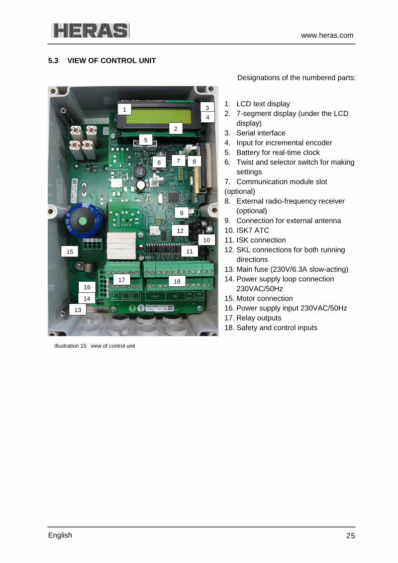
5.3 VIEW OF CONTROL UNIT
Designations of the numbered parts:
1. LCD text display 2. 7-segment display (under the LCD display) 3. Serial interface 4. Input for incremental encoder 5. Battery for real-time clock 6. Twist and selector switch for making settings 7. Communication module slot (optional) 8. External radio-frequency receiver (optional) 9. Connection for external antenna 10. ISK7 ATC 11. ISK connection 12. SKL connections for both running directions 13. Main fuse (230V/6.3A slow-acting) 14. Power supply loop connection 230VAC/50Hz 15. Motor connection 16. Power supply input 230VAC/50Hz 17. Relay outputs 18. Safety and control inputs
Illustration 15: view of control unit
1 3 4
5
6 7 8
9
10
2
11
12
14
16 17 18
13
15

www.heras.com
English 26
5.4 TWIST AND SELECTOR SWITCH Information is inputted in the integrated software of the HMD230 by means of a modern control unit that consists of one switch/button: the twist and selector switch. Visual feedback from the program to the operator is provided through the LCD screen. The twist and selector switch, located under the battery for the clock, enables the information displayed by the HMD230 to be influenced.
The twist and selector switch is operated as follows: Press briefly: confirm go back one step in the menu
Press and hold (>2s): access the main menu exit the menu
Turn*: scroll through menus change parameters
Fast turn*: scroll through menus fast change parameters fast
Illustration 16: Twist and selector switch * Turn clockwise (CW)
Turn counter-clockwise (CCW) 5.5 LCD SCREEN An LCD screen with two lines of 16 characters each has been provided to display more motor drive control information. This shows the active operating mode of the motor drive or the movement status of the motor in legible text. The background of the display is lit for as long as the twist and selector switch is operated. 20 seconds after the last entry is made, the light is switched off. It can be switched on again at any moment by turning the selector switch. The display is also properly legible in direct sunlight.
Illustration 17: Information on the LCD screen
After resetting the software or after switching on the power, the display light will blink for a few seconds. This indicates that the processor is booting; it is not a fault condition.
If, prior to a reset, the gate is in the OPEN or PARTIALLY OPEN position and “Automatic closing” is programmed, the following is displayed on the display: "Auto.Closing ON" "-------" Indicates that the automatic timer must be restarted by using keys. Without this command, the drive, after the control system has been switched on (reset), will not automatically operate.
www.heras.com
English 27
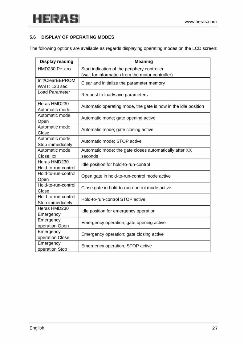
5.6 DISPLAY OF OPERATING MODES The following options are available as regards displaying operating modes on the LCD screen:
Display reading Meaning HMD230 Pe:x.xx
Start indication of the periphery controller (wait for information from the motor controller)
Init/ClearEEPROM WAIT: 120 sec.
Clear and initialize the parameter memory
Load Parameter
Request to load/save parameters
Heras HMD230 Automatic mode
Automatic operating mode, the gate is now in the idle position
Automatic mode Open
Automatic mode; gate opening active
Automatic mode Close
Automatic mode; gate closing active
Automatic mode Stop immediately
Automatic mode; STOP active
Automatic mode Close: xx
Automatic mode; the gate closes automatically after XX seconds
Heras HMD230 Hold-to-run-control
Idle position for hold-to-run-control
Hold-to-run-control Open
Open gate in hold-to-run-control mode active
Hold-to-run-control Close
Close gate in hold-to-run-control mode active
Hold-to-run-control Stop immediately
Hold-to-run-control STOP active
Heras HMD230 Emergency
Idle position for emergency operation
Emergency operation Open
Emergency operation; gate opening active
Emergency operation Close
Emergency operation; gate closing active
Emergency operation Stop
Emergency operation; STOP active

www.heras.com
English 28
5.7 DATE AND TIME DISPLAY You can permanently display the current time on the screen from the operating mode display by briefly pressing the twist and selector switch once. The clock date is shown in the top line, using the "year.month.day" format. The lower line shows the time in the 24-hour "hours:minutes:seconds" format. As standard, the control system has an automatic switch-over to summer or winter time. This can also be deactivated.
See the chapter on “Integrated real-time clock” in the HMD230 motor drive user manual.
The selected operating mode is displayed again if you briefly press the twist and selector switch or 20 seconds after operating this switch.
Illustration 18: Date and time display
5.8 SELECTING THE MENU SYSTEM The HMD230 menu system is accessed by pressing the twist and selector switch for approx. 2 seconds while the operating mode is displayed. The display then shows the text "Main menu".
Illustration 19: Display of main menu on the LCD screen
Turn the selector switch to select the individual menu options and then press the switch to activate the selected option. The first menu option in a menu level always brings you back one level, "Back in menu". The "Exit main menu" option in the main menu closes the menu display and restarts the control software. 5.9 MENU DISPLAY INSTRUCTIONS The menu system of the HMD230 can only be called up if the display has been fitted. You can use the twist and selector switch to select submenus. This offers the following possibilities: Menu:
1. Identification; displays the drive unit version. 2. Service menu; access using a password for authorized users to activate extra
functions. 3. Diagnostics; displays the states of the drive unit and the connected sensors. 4. Settings; settings parameters to control the drive unit and gate behavior.

www.heras.com
English 29
5. Clock/Calendar; date/time and calendar functions. 6. RF remote control; remote control settings.
See the chapter on "PARAMETER SETTINGS"
5.10 MENU STRUCTURE AND TEXTS THAT ARE DISPLAYED Selecting the menu brings you to the main menu level where you can choose from a number of submenus. The first menu option "Exit menu" lets you exit the main menu again after which a restart or reset brings you back in the active operating mode of the motor drive.
How many submenu levels are available depends on the password that is entered. First-level submenus can lead to second-level submenus.
The gate movement cannot be started automatically when the main menu is active. 5.11 BACKPLANE Several accessories such as photocells, lighting etc. can be connected to the backplane. The backplane has several control LEDs. The system is OK if all the green LEDs (detector 1, detector 2, Key units 1 to 3) light up while the gate is not active. If the gate gets an OPEN command, one of the orange LEDs (for the active input) will light up. If the gate gets a CLOSE command, one of the red LEDs (for the active input) will light up. The "OPEN" and "CLOSE" keys are used to open or close the gate.
Illustration 20: Backplane

www.heras.com
English 30
6 PARAMETER SETTINGS
Different parameters can be set in the drive unit's control system. The user can view several parameters in the control system. Not all parameters are accessible to the user.
See the chapter on “Parameter settings” in the HMD230 motor drive installation manual.
6.1 MENU 1 – IDENTIFICATION
Menu 1.1: Master version 6.1.1 Menu Action Display reading Explanation
H e r a s H M D 2 3 0 S 1 E N
A u t o m a t i c M o d e
1
press
and hold
Activate the main menu.
M a i n M e n u
1 I d e n t i f i c a t i o n
1.1
press briefly
I d e n t i f i c a t i o n
1 M a s t e r V e r s i o n
press briefly
The figures and the combination of numbers shown identify the software version used.
M a s t e r V e r s i o n
F U : 1 . 0 2 . 0 1 . 1
press and hold
press briefly
Exit the main menu. The control software is restarted.
M a i n M e n u
Q U I T M e n u
Menu 1.2: Gate profile 6.1.2
Menu Action Display reading Explanation
H e r a s H M D 2 3 0 S 1 E N
A u t o m a t i c M o d e
1
press
and hold
Activate the main menu.
M a i n M e n u
1 I d e n t i f i c a t i o n

www.heras.com
English 31
1.2
press briefly
turn CW
I d e n t i f i c a t i o n
2 G a t e T y p e
press briefly
The text shown is the designation of the gate for which the drive, the software and the parameters stored have been defined.
G a t e T y p e
H e r a s D e l t a F R 0 1
press and hold
press briefly
Exit the main menu. The control software is restarted.
M a i n M e n u
Q U I T M e n u
Menu 1.3: Serial number 6.1.3
Menu Action Display reading Explanation
H e r a s H M D 2 3 0 S 1 E N A u t o m a t i c M o d e
1
press
and hold
Activate the main menu. M a i n M e n u
1 I d e n t i f i c a t i o n
1.3
press briefly
I d e n t i f i c a t i o n
3 S e r i a l n u m b e r
press briefly
S e r i a l n u m b e r
0 0 0 0 0 1
press
and hold press briefly
Exit the main menu. The control software is restarted.
M a i n M e n u
Q U I T M e n u

www.heras.com
English 32
6.2 MENU 2 - SERVICE MENU The information in these menus is only relevant to authorized people.
Menu 2.1: Password entry 6.2.1 Menu Action Display reading Explanation
H e r a s H M D 2 3 0 S 1 E N
A u t o m a t i c M o d e
2
press and hold turn CW
Activate the main menu.
M a i n M e n u
2 S e r v i c e M e n u
2.1
press briefly
A password can be entered here. Depending on the password, the fitter or service engineer can access several parameters. This does not apply to the user.
S e r v i c e M e n u
1 P a s s w o r d I n p u t
press and hold
press briefly
Exit the main menu. The control software is restarted.
M a i n M e n u
Q U I T M e n u
6.3 MENU 3 - DIAGNOSIS Several gate parameters can be set and viewed in this menu.
Menu 3.1: Gate status 6.3.1 The Gate status menu summarizes all information that represents the current condition of the motor drive in combination with the gate. It can be reached as follows:
Menu Action Display reading Explanation
H e r a s H M D 2 3 0 S 1 E N
A u t o m a t i c M o d e
3
press
and hold turn CW
Activate the main menu.
M a i n M e n u
3 D i a g n o s i s

www.heras.com
English 33
3.1
press briefly
D i a g n o s i s
1 G a t e S t a t e
3.1.1
press briefly
G a t e S t a t e
1 G a t e S i t u a t i o n
press briefly
The current status of the gate which has been recognized by the software is shown. It can be OPENED / CLOSED / KEEP PART OPEN / STOPPED.
G a t e S t a t e
S T O P P E D
3.1.2
press briefly
turn CW
G a t e S t a t e
2 I n p u t : 8 7 6 5 4 3 2
press briefly
The logical values on the input terminals of the drive are displayed. The sequence matches inputs In8 to In1. An active input is indicated as "1". In the example only input In2 (stop function; break contact) is connected to 24V.
I n p u t : 8 7 6 5 4 3 2 1
V a l u e : 0 0 0 0 0 0 0 1
3.1.3
press briefly
turn CW
G a t e S t a t e
3 O u t p u t 5 4 3 2 1
press briefly
O u t p u t 5 4 3 2 1
V a l u e : 0 0 0 0 0
3.1.4
press briefly
turn CW
G a t e S t a t e
4 C o m p l e t e d C y c l
press briefly
The status of the output relays is displayed together with the corresponding logical values. An energized relay is indicated as "1". The sequence matches outputs Rel5 to Rel1. The relay Rel2 is energized in the example (status display Gate open).
C o m p l e t e d C y c l e s
4 9 / 4 9
www.heras.com
English 34
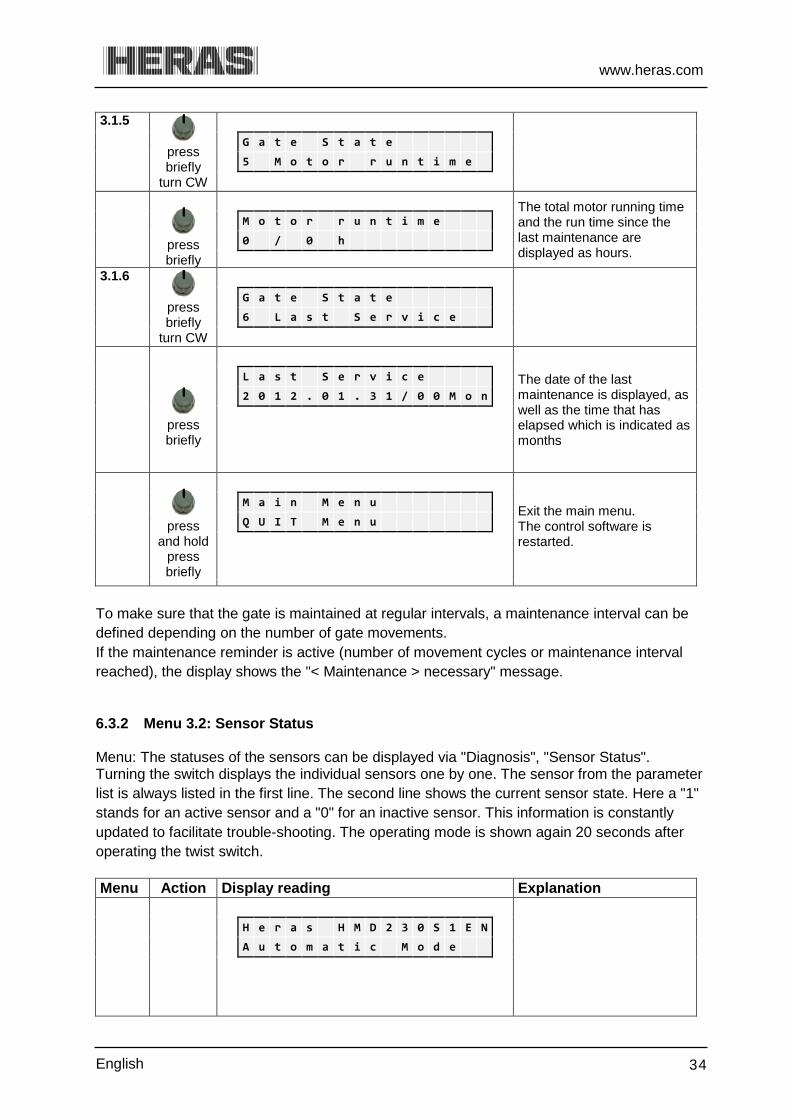
3.1.5
press briefly
turn CW
G a t e S t a t e
5 M o t o r r u n t i m e
press briefly
The total motor running time and the run time since the last maintenance are displayed as hours.
M o t o r r u n t i m e
0 / 0 h
3.1.6
press briefly
turn CW
G a t e S t a t e
6 L a s t S e r v i c e
press briefly
The date of the last maintenance is displayed, as well as the time that has elapsed which is indicated as months
L a s t S e r v i c e
2 0 1 2 . 0 1 . 3 1 / 0 0 M o n
press
and hold press briefly
Exit the main menu. The control software is restarted.
M a i n M e n u
Q U I T M e n u
To make sure that the gate is maintained at regular intervals, a maintenance interval can be defined depending on the number of gate movements. If the maintenance reminder is active (number of movement cycles or maintenance interval reached), the display shows the "< Maintenance > necessary" message.
Menu 3.2: Sensor Status 6.3.2 Menu: The statuses of the sensors can be displayed via "Diagnosis", "Sensor Status". Turning the switch displays the individual sensors one by one. The sensor from the parameter list is always listed in the first line. The second line shows the current sensor state. Here a "1" stands for an active sensor and a "0" for an inactive sensor. This information is constantly updated to facilitate trouble-shooting. The operating mode is shown again 20 seconds after operating the twist switch. Menu Action Display reading Explanation
H e r a s H M D 2 3 0 S 1 E N
A u t o m a t i c M o d e

www.heras.com
English 35
3
press and hold turn CW
Activate the main menu.
M a i n M e n u
3 D i a g n o s i s
3.2
press briefly
turn CW
D i a g n o s i s
2 S e n s o r S t a t e
press briefly turn
CCW
Turn the selector switch in a counter-clockwise direction to access the first entry in the sensor table
S t a r t o f S e n s o r s
turn CW
OPEN limit switch status (optional)
L i m i t S w i t c h O P E N
V a l u e : 0 = > 0
turn CW
CLOSED limit switch status (optional)
L i m i t S w i t c h C L O S E
V a l u e : 0 = > 0
turn CW
Part OPEN switch status (optional).
P a r t O P E N S w i t c h
V a l u e : 0 = > 0
turn CW
Current value of the incremental encoder
I n c r . E n c o d e r
V a l u e : 2 1 4 7 4 1 8 1
turn CW
Stationary safety edge for the OPEN direction of the gate
S t a t . E d g e O P E N
V a l u e : 0 = > 0
turn CW
Stationary safety edge for the CLOSING direction of the gate
S t a t . E d g e C L O S E
V a l u e : 0 0 = > 0 0 0 0
turn CW
Moving safety edge for the OPEN direction (ISK)
M o v . E d g e O P E N
V a l u e : 0 = > 0
turn CW
Moving safety edge for the CLOSING direction (ISK)
M o v . E d g e C L O S E
V a l u e : 0 = > 0

www.heras.com
English 36
turn CW
Photocell status
L i g h t b a r r i e r
V a l u e : 0 = > 0
Turn CW
Status of traffic loop A L o o p d e t e c t . A
V a l u e : 0 = > 0
turn CW
Status of traffic loop B
L o o p d e t e c t . B
V a l u e : 0 = > 0
turn CW
Turn the selector switch in a clockwise direction to access the last entry in the sensor table
E n d o f S e n s o r s
press and hold
press briefly
Exit the main menu. The control software is restarted.
M a i n M e n u
Q U I T M e n u
6.4 MENU 4 - SETTINGS Several settings can be programmed here.
Menu 4.1: Timer settings 6.4.1 6.4.1.1 Menu 4.1.1: Set lighting (coming home - leaving home) The HMD230 can drive a lamp, e.g. to automatically light the zone around the gate when the gate is moving. The lamp must be installed by an engineer (password required).
See the chapter on “Parameter settings” in the HMD230 motor drive installation manual.
The connected lighting (max. 230 VAC /3A) is activated by the drive unit as soon as a movement command is detected. After the motor is switched off, the lamp will continue to be lit for the time as set (1 to 1800 seconds). This parameter "Lighting (s)" can be set to the user's preference.

www.heras.com
English 37
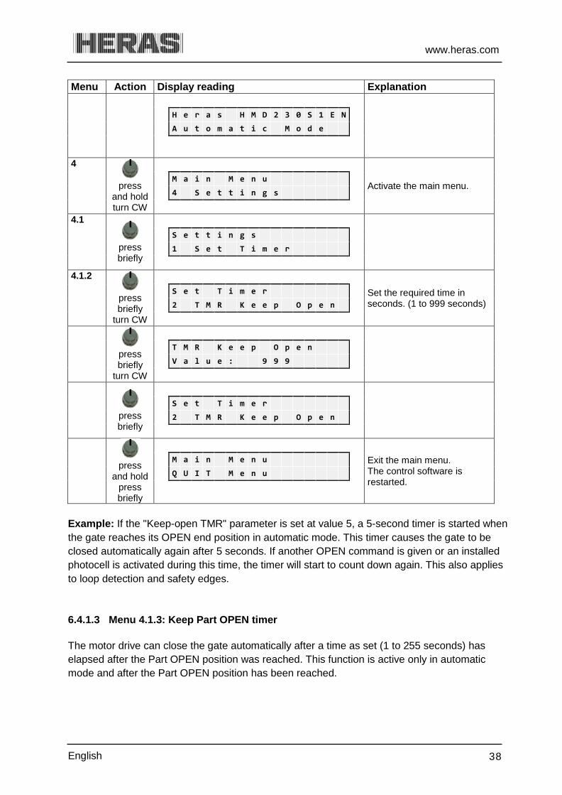
Menu Action Display reading Explanation
H e r a s H M D 2 3 0 S 1 E N
A u t o m a t i c M o d e
4
press and hold turn CW
Activate the main menu. M a i n M e n u
4 S e t t i n g s
4.1
press briefly
S e t t i n g s
1 S e t T i m e r
4.1.1
press briefly
S e t T i m e r
1 L i g h t i n g ( s )
press briefly
turn CW
Set the required time in seconds. (1 to 1800 seconds)
L i g h t i n g ( s )
V a l u e : 1 8 0 0
press briefly
S e t T i m e r
1 L i g h t i n g ( s )
press and hold
press briefly
Exit the main menu. The control software is restarted.
M a i n M e n u
Q U I T M e n u
6.4.1.2 Menu 4.1.2: Keep open timer Certain gate movements can be started automatically by pre-defined timer settings. These timer settings per menu must be displayed here. The motor drive can close the gate automatically after a time as set (1 to 999 seconds) has elapsed after the OPEN end position was reached. This function is active only in automatic mode and after the OPEN end position has been reached. The timer is off if the value equals [0].
www.heras.com
English 38
Menu Action Display reading Explanation
H e r a s H M D 2 3 0 S 1 E N
A u t o m a t i c M o d e
4
press and hold turn CW
Activate the main menu.
M a i n M e n u
4 S e t t i n g s
4.1
press briefly
S e t t i n g s
1 S e t T i m e r
4.1.2
press briefly
turn CW
Set the required time in seconds. (1 to 999 seconds)
S e t T i m e r
2 T M R K e e p O p e n
press briefly
turn CW
T M R K e e p O p e n
V a l u e : 9 9 9
press briefly
S e t T i m e r
2 T M R K e e p O p e n
press and hold
press briefly
Exit the main menu. The control software is restarted.
M a i n M e n u
Q U I T M e n u
Example: If the "Keep-open TMR" parameter is set at value 5, a 5-second timer is started when the gate reaches its OPEN end position in automatic mode. This timer causes the gate to be closed automatically again after 5 seconds. If another OPEN command is given or an installed photocell is activated during this time, the timer will start to count down again. This also applies to loop detection and safety edges. 6.4.1.3 Menu 4.1.3: Keep Part OPEN timer The motor drive can close the gate automatically after a time as set (1 to 255 seconds) has elapsed after the Part OPEN position was reached. This function is active only in automatic mode and after the Part OPEN position has been reached.

www.heras.com
English 39
Menu Action Display reading Explanation
H e r a s H M D 2 3 0 S 1 E N
A u t o m a t i c M o d e
4
press
and hold turn CW
Activate the main menu. M a i n M e n u
4 S e t t i n g s
4.1
press briefly
S e t t i n g s
1 S e t T i m e r
4.1.3
press briefly
turn CW
S e t T i m e r
3 T M R K e e p P a r t O p
press briefly
Set the required time in seconds. (1- 255 seconds)
T M R K e e p P a r t O p e n
V a l u e : 2 5 5
press briefly
S e t T i m e r
3 T M R K e e p P a r t O p
press and hold
press briefly
Exit the main menu. The control software is restarted.
M a i n M e n u
Q U I T M e n u
Example: If the "Keep Part OPEN TMR" parameter is set at value 5, a 5-second timer is started when the gate reaches its Part OPEN position in automatic mode. This timer causes the gate to be closed automatically again after 5 seconds. If another Part OPEN command is given or there is a static Part OPEN command during this time, the timer will start to count down again. This also applies to loop detection and safety edges.
Menu 4.2: End positions 6.4.2 6.4.2.1 Menu 4.2.1: Closed position for installing The motor of the HMD drive has an incremental encoder module. No further limit switches are required on the gate. The OPEN and CLOSED end positions of the gate are laid down when installing and setting the gate and the drive. The user can only change the CLOSED end position.

www.heras.com
English 40
Possible causes of a position no longer being correct are: The gate motor was disengaged and was not in exactly the same position when it was
re-engaged. The gate motor has turned after it was disengaged. In rare exceptions, when activating a safety edge the gear wheel may slip over a tooth of
the toothed bar. NOTE: ONLY engage the gate when it is in the CORRECT POSITION. Only then will the software recognise the correct end positions. Engaging the gate in the wrong position will lead to damage and the gate will operate incorrectly. In case
of doubt, contact the installer. SOLUTION:
Disengage the motor from the gate leaf (see Chapter “Disengage motor”) Ensure that the motor is at the completely closed position. If not, issue a “Close”
command. Method 1: Move the gate so that the groove in the marking plate is in line with the motor
unit (see Chapter "Marking plate"). Then re-engage the motor. The gate is now in the original position.
Method 2: Move the gate manually to the CLOSE position, re-engage the motor and reset the CLOSE position.
Menu Action Display reading Explanation
H e r a s H M D 2 3 0 S 1 E N
A u t o m a t i c M o d e
4
press
and hold turn CW
Activate the main menu.
M a i n M e n u
4 S e t t i n g s
4.2
press briefly
turn CW
S e t t i n g s
2 G a t e L i m i t s
4.2.1
press briefly
The end position has been set again. The control software is restarted.
G a t e L i m i t s
1 S e t C L O S E L i m .
Alternative method: Simultaneously Press and hold the OPEN/CLOSE keys on the backplane for 8 seconds; applies to versions 1.02 and up.

www.heras.com
English 41
Marker plate 6.4.3 In CLOSED position (gate closed) the slot of the marker plate must be aligned to the side of the drive unit. If this is not the case, then manually move the gate to its CLOSED position.
Marker plate
Illustration 21: Marker plate on a Delta
Marker plate
Illustration 22: Marker plate on uGate / iGate
Attention: If there is a power failure while the gate is being moved, it may no longer be possible to save the gate position. This is indicated by the fact that the gate can no
longer be moved in automatic mode. You must then also manually move the gate to its CLOSED position and set the position again. 6.5 MENU 5 - CLOCK/CALENDAR The clock module integrated in the HMD230 can be used to move the gate automatically, on the basis of an exact time schedule. If the power supply to the motor drive is switched off, the date and time are kept up to date for a couple of weeks. Automatic switch-over to summer or winter time take place, according to EU rules. As a result, the clock is put forward one hour at 2 a.m. CET on the last Sunday of March and it is put back one hour at 3 a.m. CET on the last Sunday of October.

www.heras.com
English 42
Menu 5.1: Clock display 6.5.1 Press the selector switch once to display the current date and time for 20 seconds. You can access this menu option as follows: Menu Action Display reading Explanation
H e r a s H M D 2 3 0 S 1 E N
A u t o m a t i c M o d e
5
press and hold turn CW
Activate the main menu.
M a i n M e n u
5 C l o c k / C a l e n d a r
5.1
press briefly
C l o c k / C a l e n d a r
1 D i s p l a y C l o c k
press briefly
The current date and time are displayed.
D a t e : 2 0 1 2 . 0 4 . 0 1
T i m e : 1 6 : 3 4 : 4 5
press and hold
press briefly
Exit the main menu. The control software is restarted.
M a i n M e n u
Q U I T M e n u
Menu 5.2: Setting date/time 6.5.2
The internal clock of the HMD230 has been factory-set. If this time ever differs from the actual current time, the clock can be set as follows: Menu Action Display reading Explanation
H e r a s H M D 2 3 0 S 1 E N
A u t o m a t i c M o d e
5
press and hold turn CW
Activate the main menu.
M a i n M e n u
5 C l o c k / C a l e n d a r
5.2
press briefly
turn CW
C l o c k / C a l e n d a r
2 S e t D a t e / T i m e

www.heras.com
English 43
press briefly
S e t D a t e / T i m e
Y e a r
turning press briefly
Set the last two digits of the current year.
Y e a r
V a l u e : 2 0 1 2
turn CW press briefly
S e t D a t e / T i m e
M o n t h
turning press briefly
Set the current month.
M o n t h
V a l u e : 0 4
turn CW press briefly
S e t D a t e / T i m e
D a y
turning press briefly
Set the current day.
D a y
V a l u e : 0 1
turn CW
press briefly
S e t D a t e / T i m e
H o u r
turning press briefly
Set the current hour.
H o u r
V a l u e : 1 6
turn CW press briefly
S e t D a t e / T i m e
M i n u t e
turning press briefly
Set the current minutes.
M i n u t e
V a l u e : 3 4
turn CW
press briefly
S e t D a t e / T i m e
S e c o n d

www.heras.com
English 44
turning press briefly
S e c o n d
V a l u e : 4 5
turn CW press briefly
S e t D a t e / T i m e
D a y l i g h t S a v i n g
turning press briefly
Set to "1" (default) for automatic summer time switch-over according to the EU rules.
D a y l i g h t S a v i n g
V a l u e : 1
turning press briefly
S e t D a t e / T i m e
N o w D a y l i g h t S a v ?
turning
Set "0" in winter; and set to "1" if the summer time has started
N o w D a y l i g h t S a v ?
V a l u e : 1
press and hold
press briefly
Exit the main menu. The control software is restarted.
M a i n M e n u
Q U I T M e n u
Calendar functions of the motor drive 6.5.3 In automatic mode, the calendar functions of the master drive can be used to influence the gate behavior in different ways at specific times. Only available for profiles 3+4. Some commands are available for gate actions. They can be called up at carefully defined times. The times and commands can be repeated for the seven week days, with a weekly cycle. However, other combinations of times and commands of a higher priority (e.g. for holidays) can be planned in a yearly calendar to suppress this weekly recurring time process. This enables the automatic gate behavior to be defined individually in advance by making the relevant calendar entries.
Information: The calendar function in the motor drive control system is a paid option which must be enabled by the engineer once and is then available to the customer.
Otherwise, the calendars will not be visible. Note: When programming, beware that "Automatic closing" is the default gate mode. The function to be programmed forms an exception to this behavior. Every function must have a start time and an end time.

www.heras.com
English 45
Possible calendar functions (actions that the motor drive can perform via a calendar) Functions Action No action No gate action (hold position) Keep open position Keep the gate statically in OPEN position
(The gate cannot be closed) Leave open pos. Leave the static OPEN position of the gate
(The gate can close again) Auto.close.OFF Deactivate the automatic closing function
(The keep-open time is ignored) Auto.close.ON Activate the automatic closing function
(Activate the keep-open time again) Keep Part Open ON
Activate the keep-open function for the Part OPEN position (The gate will move only between the Part OPEN and OPEN positions)
Keep Part Open OFF
Deactivate the Keep Part OPEN function (The gate can close again)
OPEN gate The gate moves to the OPEN position. CLOSE gate The gate moves to the OPEN position (if possible) Gate Part OPEN The gate moves to the Part OPEN position (if possible)
Menu 5.3: Activating the calendar 6.5.4 The following setting can be used to activate or deactivate the total calendar functions without you having to change the specific individual entries. Menu Action Display reading Explanation
H e r a s H M D 2 3 0 S 1 E N
A u t o m a t i c M o d e
5
press
and hold turn CW
Activate the main menu.
M a i n M e n u
5 C l o c k / C a l e n d a r
5.3
press briefly
turn CW
C l o c k / C a l e n d a r
3 C a l . A c t i v a t i o n
press briefly turn
0 = all calendar functions off. 1 = calendar on.
C a l . A c t i v a t i o n
V a l u e : 1

www.heras.com
English 46
press and hold
press briefly
Exit the main menu. The control software is restarted
M a i n M e n u
Q U I T M e n u
Menu 5.4: Displaying the weekly calendar 6.5.5 A maximum of 20 different switching times and the corresponding functions (gate actions) can be entered in the weekly calendar for every individual week day (Sunday through Saturday). Only the times entered are shown in the display mode for the weekly calendar. The empty memory positions are skipped. The weekly calendar can be displayed as follows: Menu Action Display reading Explanation
H e r a s H M D 2 3 0 S 1 E N
A u t o m a t i c M o d e
5
press and hold turn CW
Activate the main menu.
M a i n M e n u
5 C l o c k / C a l e n d a r
5.4
press briefly
turn CW
C l o c k / C a l e n d a r
4 D i s p . W e e k C a l .
press briefly turn
Shows the switching time on the right. Turn the selector switch to browse through all entries in the calendar
M o n d a y 1 2 : 3 0
H o l d P a r t . O P E N
turn CW
Shows the end of all actions entered. Or is displayed if no week clock has been set.
D i s p . W e e k C a l .
E N D
press and hold
press briefly
Exit the main menu. The control software is restarted.
M a i n M e n u
Q U I T M e n u

www.heras.com
English 47
Menu 5.5: Changing the weekly calendar 6.5.6 6.5.6.1 Menu 5.5.1: Week day setting Proceed as follows to add new entries to the weekly calendar or change existing entries: Menu Action Display reading Explanation
H e r a s H M D 2 3 0 S 1 E N
A u t o m a t i c M o d e
5
press and hold turn CW
Activate the main menu.
M a i n M e n u
5 C l o c k / C a l e n d a r
5.5
press briefly
turn CW
C l o c k / C a l e n d a r
5 E d i t W e e k C a l .
5.5.1
press briefly
E d i t W e e k C a l .
1 S e t W e e k d a y s
press briefly
A free memory position for a week day is displayed.
S u n d a y
turn CW
Select the week day.
M o n d a y
press briefly
Call up the entry mode for the hours.
M o n d a y 0 0 :
turning
Select the hour for the switching time.
M o n d a y 1 2 :
press briefly
Call up the entry mode for the minutes.
M o n d a y 1 2 : 0 0

www.heras.com
English 48
turning
M o n d a y 1 2 : 3 0
press briefly
M o n d a y 1 2 : 3 0
N o A c t i o n
turn CW
Select the appropriate switching function.
M o n d a y 1 2 : 3 0
H o l d P a r t . O P E N
press briefly
Press the selector switch to insert the full entry into the week day on the calendar, sorted by time. The next free memory location of the calendar is shown.
M o n d a y
turn CW
The end of the weekly calendar.
S e t W e e k d a y s
E N D
press and hold
press briefly
Exit the main menu. The control software is restarted
M a i n M e n u
Q U I T M e n u
Programming several actions at the same time is not possible.
6.5.6.2 Menu 5.5.1: Copying a day in the weekly calendar All entries for a week day can be copied to another week day on the weekly calendar, provided that no entries have been made so far in the week day which the data is to be copied to. Menu Action Display reading Explanation
H e r a s H M D 2 3 0 S 1 E N
A u t o m a t i c M o d e
5
press
and hold turn CW
Activate the main menu.
M a i n M e n u
5 C l o c k / C a l e n d a r

www.heras.com
English 49
5.5
press briefly
turn CW
C l o c k / C a l e n d a r
5 E d i t W e e k C a l .
5.5.1
press briefly
E d i t W e e k C a l .
1 S e t W e e k d a y s
press briefly turn
Select the destination day to which the entry is to be copied.
T u e s d a y
press briefly
Call up the entry mode for hours.
T u e s d a y 0 0 :
turn
CCW
Select the day from which the entry is to be copied.
T u e s d a y C o p y
o f : M o n d a y
press briefly
Copy entry (here from Monday to Tuesday).
T u e s d a y
D o n e
press
and hold
The end of the weekly calendar.
S e t W e e k d a y s
E N D
press and hold
press briefly
Exit the main menu. The control software is restarted.
M a i n M e n u
Q U I T M e n u
6.5.6.3 Menu 5.5.1: Deleting individual entries You can delete individual entries for a week day on the weekly calendar as follows: Menu Action Display reading Explanation
H e r a s H M D 2 3 0 S 1 E N
A u t o m a t i c M o d e

www.heras.com
English 50
5
press and hold turn CW
Activate the main menu.
M a i n M e n u
5 C l o c k / C a l e n d a r
5.5
press briefly
turn CW
C l o c k / C a l e n d a r
5 E d i t W e e k C a l .
5.5.1
press briefly
E d i t W e e k C a l .
1 S e t W e e k d a y s
press briefly
turn CW
Select the day to be deleted.
M o n d a y 1 2 : 3 0
N o A c t i o n
press briefly turn
CCW
M o n d a y
D e l e t e R e c o r d ?
press briefly
Delete the entry from the week day on the calendar.
M o n d a y
D o n e
press
and hold
The end of the weekly calendar.
S e t W e e k d a y s
E N D
press and hold
press briefly
Exit the main menu. The control software is restarted.
M a i n M e n u
Q U I T M e n u
6.5.6.4 Menu 5.5.1: Deleting a week day You can also delete all entries for a week day from the weekly calendar after selecting the first entry for the week day in question: Menu Action Display reading Explanation
H e r a s H M D 2 3 0 S 1 E N
A u t o m a t i c M o d e
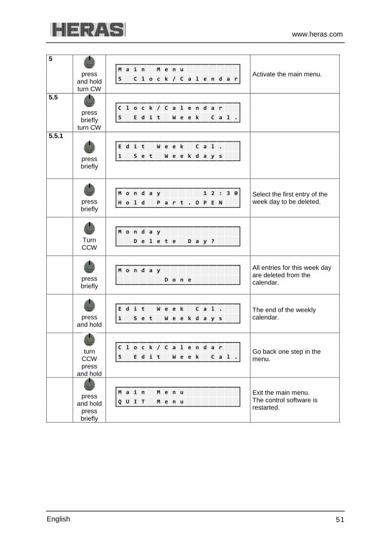
www.heras.com
English 51
5
press and hold turn CW
Activate the main menu.
M a i n M e n u
5 C l o c k / C a l e n d a r
5.5
press briefly
turn CW
C l o c k / C a l e n d a r
5 E d i t W e e k C a l .
5.5.1
press briefly
E d i t W e e k C a l .
1 S e t W e e k d a y s
press briefly
Select the first entry of the week day to be deleted.
M o n d a y 1 2 : 3 0
H o l d P a r t . O P E N
Turn CCW
M o n d a y
D e l e t e D a y ?
press briefly
All entries for this week day are deleted from the calendar.
M o n d a y
D o n e
press
and hold
The end of the weekly calendar.
E d i t W e e k C a l .
1 S e t W e e k d a y s
turn CCW press
and hold
Go back one step in the menu.
C l o c k / C a l e n d a r
5 E d i t W e e k C a l .
press and hold
press briefly
Exit the main menu. The control software is restarted.
M a i n M e n u
Q U I T M e n u

www.heras.com
English 52
6.5.6.5 Menu 5.5.2: Deleting the weekly calendar You can also delete all entries for the entire weekly calendar as follows: Menu Action Display reading Explanation
H e r a s H M D 2 3 0 S 1 E N
A u t o m a t i c M o d e
5
press and hold turn CW
Activate the main menu.
M a i n M e n u
5 C l o c k / C a l e n d a r
5.5
press briefly
turn CW
C l o c k / C a l e n d a r
5 E d i t W e e k C a l .
5.5.2
press briefly
turn CW
E d i t W e e k C a l .
2 D e l e t e W e e k
press briefly
D e l e t e W e e k
D o n e
press and hold
press briefly
Exit the main menu. The control software is restarted.
M a i n M e n u
Q U I T M e n u
Menu 5.6: Displaying the yearly calendar 6.5.7 The yearly calendar is located over the weekly calendar on the control system. The yearly calendar can store 20 different switching times and corresponding gate actions per day for a total of 40 days. If switching times have been entered in the yearly calendar for a certain date, only the relevant entry will be applied with priority on the day in question and the weekly calendar will be ignored for this day. Only the times entered are shown in the display mode for the yearly calendar. The empty memory positions are skipped. The yearly calendar can be displayed as follows: Menu Action Display reading Explanation
H e r a s H M D 2 3 0 S 1 E N
A u t o m a t i c M o d e

www.heras.com
English 53
5
press and hold turn CW
Activate the main menu.
M a i n M e n u
5 C l o c k / C a l e n d a r
5.6
press briefly
turn CW
C l o c k / C a l e n d a r
6 D i s p . Y e a r C a l .
press briefly
Shows the switching time on the right. Turn the selector switch to browse through all entries in the calendar
2 0 1 2 . 0 6 . 1 7 1 2 : 3 0
H o l d P a r t . O P E N
press briefly
Shows the end of all actions entered. Or is displayed if no week clock has been set.
D i s p . Y e a r C a l .
E N D
press and hold
press briefly
Exit the main menu. The control software is restarted.
M a i n M e n u
Q U I T M e n u
Information: Other gate actions planned on the weekly calendar can be suppressed specifically for one day in the year (e.g. a national holiday) by using the "No action" function.
Menu 5.7: Changing the yearly calendar 6.5.8
You can add new entries to the yearly calendar or change existing entries. 6.5.8.1 Menu 5.7.1: Set day Menu Action Display reading Explanation
H e r a s H M D 2 3 0 S 1 E N
A u t o m a t i c M o d e
5
press and hold turn CW
Activate the main menu.
M a i n M e n u
5 C l o c k / C a l e n d a r
5.7
press briefly
turn CW
C l o c k / C a l e n d a r
7 E d i t W e e k C a l .

www.heras.com
English 54
5.7.1
Press briefly
E d i t W e e k C a l .
1 S e t D a y
press briefly
An empty memory position for a date is displayed.
2 0
press briefly
turn CW
Call up the entry mode for the year.
2 0 1 1 .
turn CW
Select the year for the switching time.
2 0 1 2 .
press briefly
Call up the entry mode for the month.
2 0 1 2 . 0 1 .
turn CW
Select the month for the switching time.
2 0 1 2 . 0 6 .
press briefly
Call up the entry mode for the day.
2 0 1 2 . 0 6 . 0 1
turn CW
Select the day for the switching time.
2 0 1 2 . 0 6 . 1 7
press briefly
Call up the entry mode for the hours.
2 0 1 2 . 0 6 . 1 7 0 0 :
turn CW
Select the hour for the switching time.
2 0 1 2 . 0 6 . 1 7 1 2 :
press briefly
Call up the entry mode for the minutes.
2 0 1 2 . 0 6 . 1 7 1 2 : 0 0

www.heras.com
English 55
turn CW
Select the minutes for the switching time.
2 0 1 2 . 0 6 . 1 7 1 2 : 3 0
press briefly
Call up the entry mode for the motor drive function for this switching time
2 0 1 2 . 0 6 . 1 7 1 2 : 3 0
N o A c t i o n
turn CW
Turn the selector switch in a clockwise direction to select the function.
2 0 1 2 . 0 6 . 1 7 1 2 : 3 0
H o l d P a r t . O P E N
press briefly
Press the selector switch to insert the full entry into the yearly calendar, sorted by time. The next memory location of the calendar will be displayed.
2 0 1 2 . 0 6 . 1 7
turn CW
Shows the end of the yearly calendar.
S e t D a y
E N D
turn CCW press
and hold
Go back one step in the menu.
C l o c k / C a l e n d a r
7 E d i t W e e k C a l .
press and hold
press briefly
Exit the main menu. The control software is restarted.
M a i n M e n u
Q U I T M e n u
Information: Changes to the date (and not only the switching time) can only be made in the first entry for this date and always apply to all entries for this day. The yearly calendar is sorted, i.e. an older date is put before a more recent date.
6.5.8.2 Menu 5.7.1: Copying a day in the yearly calendar All entries for a certain day can be copied to another day with a different date on the yearly calendar. However, a new date has to be entered for this.
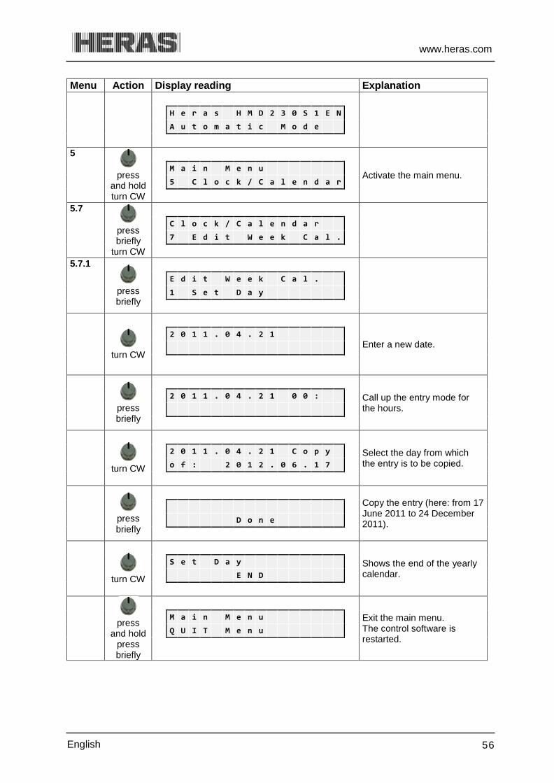
www.heras.com
English 56
Menu Action Display reading Explanation
H e r a s H M D 2 3 0 S 1 E N
A u t o m a t i c M o d e
5
press and hold turn CW
Activate the main menu. M a i n M e n u
5 C l o c k / C a l e n d a r
5.7
press briefly
turn CW
C l o c k / C a l e n d a r
7 E d i t W e e k C a l .
5.7.1
press briefly
E d i t W e e k C a l .
1 S e t D a y
turn CW
Enter a new date.
2 0 1 1 . 0 4 . 2 1
press briefly
Call up the entry mode for the hours.
2 0 1 1 . 0 4 . 2 1 0 0 :
turn CW
Select the day from which the entry is to be copied.
2 0 1 1 . 0 4 . 2 1 C o p y
o f : 2 0 1 2 . 0 6 . 1 7
press briefly
Copy the entry (here: from 17 June 2011 to 24 December 2011).
D o n e
turn CW
Shows the end of the yearly calendar.
S e t D a y
E N D
press and hold
press briefly
Exit the main menu. The control software is restarted.
M a i n M e n u
Q U I T M e n u

www.heras.com
English 57
6.5.8.3 Menu 5.7.1: Deleting individual entries You can delete individual entries for a specific day on the yearly calendar as follows: Menu Action Display reading Explanation
H e r a s H M D 2 3 0 S 1 E N
A u t o m a t i c M o d e
5
press and hold turn CW
Activate the main menu.
M a i n M e n u
5 C l o c k / C a l e n d a r
5.7
press briefly
turn CW
C l o c k / C a l e n d a r
7 E d i t W e e k C a l .
5.7.1
press briefly
E d i t W e e k C a l .
1 S e t D a y
press briefly turn
2 0 1 1 . 0 6 . 1 7 1 2 : 3 0
H o l d P a r t . O P E N
press briefly turn
CCW
A question is displayed.
2 0 1 1 . 0 6 . 1 7
D e l e t e R e c o r d ?
press briefly
The entry in question is deleted from the calendar.
D o n e
turn CW
Shows the end of the yearly calendar.
S e t D a y
E N D
press and hold
press briefly
Exit the main menu. The control software is restarted.
M a i n M e n u
Q U I T M e n u
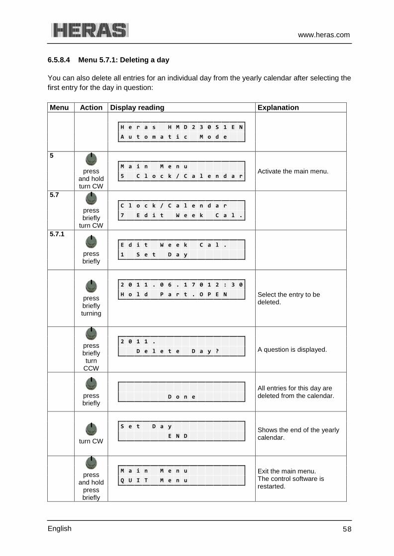
www.heras.com
English 58
6.5.8.4 Menu 5.7.1: Deleting a day You can also delete all entries for an individual day from the yearly calendar after selecting the first entry for the day in question: Menu Action Display reading Explanation
H e r a s H M D 2 3 0 S 1 E N
A u t o m a t i c M o d e
5
press and hold turn CW
Activate the main menu.
M a i n M e n u
5 C l o c k / C a l e n d a r
5.7
press briefly
turn CW
C l o c k / C a l e n d a r
7 E d i t W e e k C a l .
5.7.1
press briefly
E d i t W e e k C a l .
1 S e t D a y
press briefly turning
Select the entry to be deleted.
2 0 1 1 . 0 6 . 1 7 0 1 2 : 3 0
H o l d P a r t . O P E N
press briefly turn
CCW
A question is displayed.
2 0 1 1 .
D e l e t e D a y ?
press briefly
All entries for this day are deleted from the calendar.
D o n e
turn CW
Shows the end of the yearly calendar.
S e t D a y
E N D
press and hold
press briefly
Exit the main menu. The control software is restarted.
M a i n M e n u
Q U I T M e n u

www.heras.com
English 59
6.5.8.5 Menu 5.7.2: Deleting the entire yearly calendar You can also delete all entries for the entire yearly calendar as follows: Menu Action Display reading Explanation
H e r a s H M D 2 3 0 S 1 E N
A u t o m a t i c M o d e
5
press and hold turn CW
Activate the main menu.
M a i n M e n u
5 C l o c k / C a l e n d a r
5.7
press briefly
turn CW
C l o c k / C a l e n d a r
7 E d i t W e e k C a l .
5.7.2
press briefly
turn CW
E d i t W e e k C a l .
2 D e l . Y e a r C a l .
press briefly
D e l . Y e a r C a l .
D o n e
press and hold
press briefly
Exit the main menu. The control software is restarted.
M a i n M e n u
Q U I T M e n u
6.6 MENU 6 - RF REMOTE CONTROL The motor drive features a slot for a radio-frequency receiver module. An 868 MHz receiver module with FM modulation is used and the constant share of the "Rolling Code" of the HERAS transmitter used is analyzed. A corresponding hand transmitter enables the following functions of the motor drive to be remotely controlled: "OPEN function" left-hand top key "CLOSE function" right-hand top key "STOP function" large bottom key "PART OPEN function"* simultaneously press and
hold the left and right keys * Only in combination with an activated "Part open" position
Illustration 23: Heras transmitter

www.heras.com
English 60
The keys can also be individually programmed, see “Teaching hand transmitters”. Editing options (like teaching the hand transmitter and deleting) are available via the menu structure of the motor drive. A maximum of 150 hand transmitters can be taught.
Information: Gate movements can only be activated by means of the remote control if the motor drive is working in automatic mode.
An external antenna must be connected to the corresponding connector of the motor drive PCB (see illustration 13, pos. 9). The internal core of the coax cable of the antenna is connected to the right-hand terminal (near the housing side). The antenna shield is connected to the most inward/left-hand terminal.
Menu 6.1: Displaying the number of hand transmitters 6.6.1 A separate storage location is reserved in the memory of the motor drive for each hand transmitter. The total number of transmitters stored can be displayed by means of the menu option "Active transmitters". Menu Action Display reading Explanation
H e r a s H M D 2 3 0 S 1 E N
A u t o m a t i c M o d e
6
press and hold turn CW
Activate the main menu.
M a i n M e n u
6 R F R e m o t e C t r l
6.1
press briefly
R F R e m o t e C t r l .
1 A c t i v e T r a n s m i
press briefly
Display of the number of hand transmitters taught.
A c t i v e T r a n s m i t .
0
press and hold
press briefly
Exit the main menu. The control software is restarted.
M a i n M e n u
Q U I T M e n u

www.heras.com
English 61
Menu 6.2: Teaching hand transmitters 6.6.2 Every hand transmitter which is used must be taught the commands to operate the motor drive once. This is done as follows: Menu Action Display reading Explanation
H e r a s H M D 2 3 0 S 1 E N
A u t o m a t i c M o d e
6
press and hold
turn CW
M a i n M e n u
6 R F R e m o t e C t r l
6.2
press briefly
turn CW
R F R e m o t e C t r l .
2 P r o g r . T r a n s m i
press briefly
Twenty seconds are available for this function. After recognizing and saving the transmission code, a numeric value is displayed for 2 seconds. This is the value of the received signal together with the storage position.
"RF# xxxx" "Pos.: p "
If within twenty seconds after activating the menu the program does not recognize a valid code the menu is displayed again.
P r o g r . T r a n s m i t .
. . . .
Press the
hand transmitter
button
When the transmission code has been recognized and saved, the menu is displayed again. Other hand transmitters can be programmed by activating the menu again. Check the number of transmitters stored by means of the menu option "Active transmitters".
R F # : 1 2 3 4 5 6 7 8 9
P o s . : 1 . .
Exit the main menu. The control software is restarted. Check the key functions that have been taught in "automatic mode".
R F R e m o t e C t r l .
2 P r o g r . T r a n s m i

www.heras.com
English 62
press and hold press briefly
Exit the main menu. The control software is restarted.
M a i n M e n u
Q U I T M e n u
Menu 6.3-6.6: Programming hand transmitter buttons 6.6.3 If functions programmed as standard for the hand transmitter are inadequate, another four functions can be programmed. The individual buttons can be programmed using the menu below. 6.6.3.1 Menu 6.3: Programming hand transmitter button OPEN Menu Action Display reading Explanation
H e r a s H M D 2 3 0 S 1 E N
A u t o m a t i c M o d e
6
press and
hold turn CW
Activate the main menu.
M a i n M e n u
6 R F R e m o t e C t r l
6.3
press briefly
R F R e m o t e C t r l .
3 P r o g . K e y O P E N
press briefly
Program OPEN function P r o g . K e y O P E N
. . . .
Press the
hand transmitter
button
After recognizing and saving the transmission code, a numeric value is displayed for 2 seconds. This is the value of the received signal together with the storage position.
R F # : 1 2 3 4 5 6 7 8 9
P o s . : 2 O p
R F R e m o t e C t r l .
3 P r o g . K e y O P E N
press and
hold press briefly
Exit the main menu. The control software is restarted. Check the key functions that have been taught in "automatic mode".
M a i n M e n u
Q U I T M e n u

www.heras.com
English 63
6.6.3.2 Menu 6.4: Programming hand transmitter button CLOSE Menu Action Display reading Explanation
H e r a s H M D 2 3 0 S 1 E N
A u t o m a t i c M o d e
6
press and hold
turn CW
Activate the main menu.
M a i n M e n u
6 R F R e m o t e C t r l
6.4
press briefly
R F R e m o t e C t r l .
4 P r o g . K e y C L O S E
press briefly
Program CLOSE function
P r o g . K e y C L O S E
. . . .
Press the hand
transmitter button
After recognizing and saving the transmission code, a numeric value is displayed for 2 seconds. This is the value of the received signal together with the storage position.
R F # : 1 2 3 4 5 6 7 8 9
P o s . : 3 C l
R F R e m o t e C t r l .
4 P r o g . K e y C L O S E
press and
hold press
Exit the main menu. The control software is restarted. Check the key functions that have been taught in "automatic mode".
M a i n M e n u
Q U I T M e n u
6.6.3.3 Menu 6.5: Programming hand transmitter button PART OPEN Menu Action Display reading Explanation
H e r a s H M D 2 3 0 S 1 E N
A u t o m a t i c M o d e
6
press and hold
turn CW
Activate the main menu.
M a i n M e n u
6 R F R e m o t e C t r l
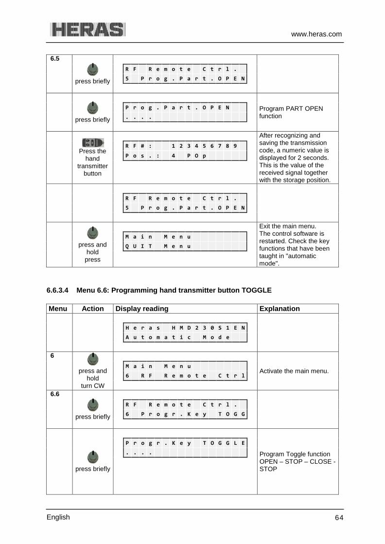
www.heras.com
English 64
6.5
press briefly
R F R e m o t e C t r l .
5 P r o g . P a r t . O P E N
press briefly
Program PART OPEN function
P r o g . P a r t . O P E N
. . . .
Press the hand
transmitter button
After recognizing and saving the transmission code, a numeric value is displayed for 2 seconds. This is the value of the received signal together with the storage position.
R F # : 1 2 3 4 5 6 7 8 9
P o s . : 4 P O p
R F R e m o t e C t r l .
5 P r o g . P a r t . O P E N
press and
hold press
Exit the main menu. The control software is restarted. Check the key functions that have been taught in "automatic mode".
M a i n M e n u
Q U I T M e n u
6.6.3.4 Menu 6.6: Programming hand transmitter button TOGGLE Menu Action Display reading Explanation
H e r a s H M D 2 3 0 S 1 E N
A u t o m a t i c M o d e
6
press and hold
turn CW
Activate the main menu.
M a i n M e n u
6 R F R e m o t e C t r l
6.6
press briefly
R F R e m o t e C t r l .
6 P r o g r . K e y T O G G
press briefly
Program Toggle function OPEN – STOP – CLOSE - STOP
P r o g r . K e y T O G G L E
. . . .
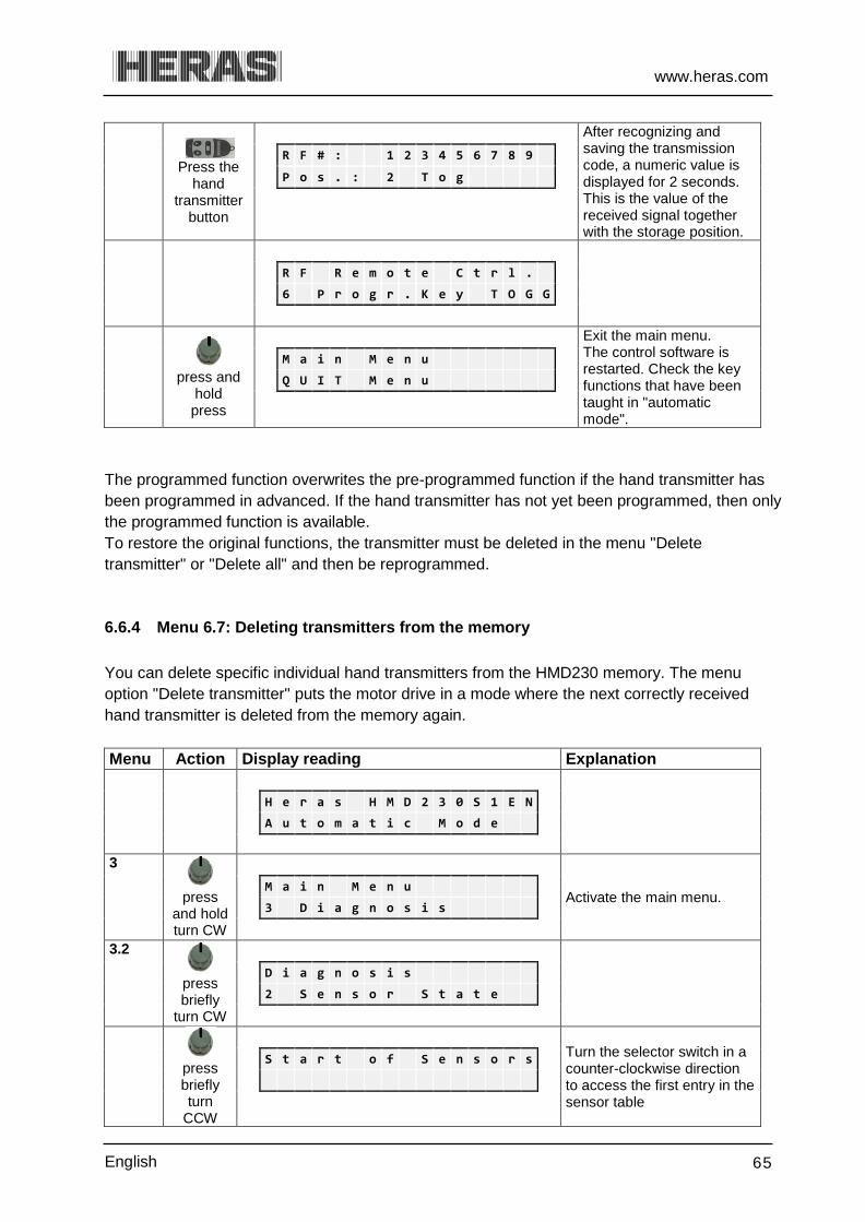
www.heras.com
English 65
Press the hand
transmitter button
After recognizing and saving the transmission code, a numeric value is displayed for 2 seconds. This is the value of the received signal together with the storage position.
R F # : 1 2 3 4 5 6 7 8 9
P o s . : 2 T o g
R F R e m o t e C t r l .
6 P r o g r . K e y T O G G
press and
hold press
Exit the main menu. The control software is restarted. Check the key functions that have been taught in "automatic mode".
M a i n M e n u
Q U I T M e n u
The programmed function overwrites the pre-programmed function if the hand transmitter has been programmed in advanced. If the hand transmitter has not yet been programmed, then only the programmed function is available. To restore the original functions, the transmitter must be deleted in the menu "Delete transmitter" or "Delete all" and then be reprogrammed.
Menu 6.7: Deleting transmitters from the memory 6.6.4 You can delete specific individual hand transmitters from the HMD230 memory. The menu option "Delete transmitter" puts the motor drive in a mode where the next correctly received hand transmitter is deleted from the memory again. Menu Action Display reading Explanation
H e r a s H M D 2 3 0 S 1 E N
A u t o m a t i c M o d e
3
press and hold turn CW
Activate the main menu.
M a i n M e n u
3 D i a g n o s i s
3.2
press briefly
turn CW
D i a g n o s i s
2 S e n s o r S t a t e
press briefly turn
CCW
Turn the selector switch in a counter-clockwise direction to access the first entry in the sensor table
S t a r t o f S e n s o r s
www.heras.com
English 66
turn CW
OPEN limit switch status (optional)
L i m i t S w i t c h O P E N
V a l u e : 0 = > 0
turn CW
CLOSED limit switch status (optional)
L i m i t S w i t c h C L O S E
V a l u e : 0 = > 0
turn CW
Part OPEN switch status (optional).
P a r t O P E N S w i t c h
V a l u e : 0 = > 0
turn CW
Current value of the incremental encoder
I n c r . E n c o d e r
V a l u e : 2 1 4 7 4 1 8 1
turn CW
Stationary safety edge for the OPEN direction of the gate
S t a t . E d g e O P E N
V a l u e : 0 = > 0
turn CW
Stationary safety edge for the CLOSING direction of the gate
S t a t . E d g e C L O S E
V a l u e : 0 0 = > 0 0 0 0
turn CW
Moving safety edge for the OPEN direction (ISK)
M o v . E d g e O P E N
V a l u e : 0 = > 0
turn CW
Moving safety edge for the CLOSING direction (ISK)
M o v . E d g e C L O S E
V a l u e : 0 = > 0
turn CW
Photocell status
L i g h t b a r r i e r
V a l u e : 0 = > 0
Turn CW
Status of traffic loop A
L o o p d e t e c t . A
V a l u e : 0 = > 0
turn CW
Status of traffic loop B
L o o p d e t e c t . B
V a l u e : 0 = > 0
www.heras.com
English 67
turn CW
Turn the selector switch in a clockwise direction to access the last entry in the sensor table
E n d o f S e n s o r s
press and hold
press briefly
Exit the main menu. The control software is restarted.
M a i n M e n u
Q U I T M e n u
Menu 6.8: Deleting hand transmitter function 6.6.5
Menu Action Display reading Explanation
H e r a s H M D 2 3 0 S 1 E N
A u t o m a t i c M o d e
6
press
and hold turn CW
Activate the main menu. M a i n M e n u
6 R F R e m o t e C t r l
6.8
press briefly
turn CW
R F R e m o t e C t r l .
8 D e l e t e P l a c e N o
press briefly
Select the desired position e.g. Pos.: 1 Op Repeat if you want to delete multiple functions
D e l e t e P l a c e N o .
P o s . : 1 . .
press briefly
Confirm the following display "Delete Entry?"
D e l e t e P l a c e N o .
D e l e t e R e c o r d ?
press briefly
"Done" indicates that the function has been deleted.
D e l e t e P l a c e N o .
D o n e
turn CW
D e l e t e P l a c e N o .
E n d
M a i n M e n u
Q U I T M e n u
www.heras.com
English 68
Menu 6.9: Deleting all transmitters from the memory 6.6.6 All transmitters stored in the memory of the HMD230 can be deleted using the menu option "Delete all". Menu Action Display reading Explanation
H e r a s H M D 2 3 0 S 1 E N
A u t o m a t i c M o d e
6
press and hold turn CW
Activate the main menu.
M a i n M e n u
6 R F R e m o t e C t r l
6.9
press briefly
turn CW
0
7 T M R A u t o m . O p e
press briefly
All transmitters have been deleted. Check the number of transmitters stored by means of the menu option "Active transmitters".
R F R e m o t e C t r l .
9 D e l e t e A l l
press and hold
press briefly
Exit the main menu. The control software is restarted.
M a i n M e n u
Q U I T M e n u
6.7 LED lighting operation
The iGate can optionally be provided with LED strips. The light color can be set on the LED control unit. The LED lights will only switch on if the gate is closed and the dusk to dawn lighting is on. Also the lights can be activated at a specific time, using a separate week timer (optional). This enables you to set the gate lights such that they are only on at night. This can also be done automatically using a light/dark switch. When darkness falls, the lights on the gate will go on.
See the manuals for the LED control unit and the week timer for instructions on how to operate and program them.
Illustration 24: LED control unit
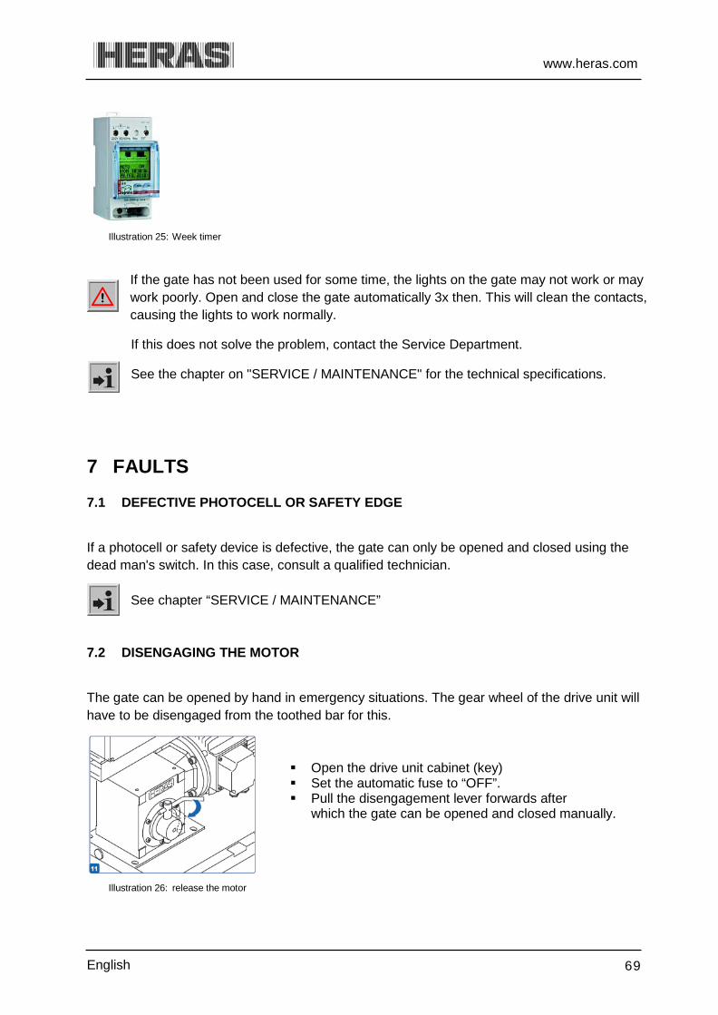
www.heras.com
English 69
Illustration 25: Week timer
If the gate has not been used for some time, the lights on the gate may not work or may work poorly. Open and close the gate automatically 3x then. This will clean the contacts, causing the lights to work normally.
If this does not solve the problem, contact the Service Department.
See the chapter on "SERVICE / MAINTENANCE" for the technical specifications.
7 FAULTS 7.1 DEFECTIVE PHOTOCELL OR SAFETY EDGE
If a photocell or safety device is defective, the gate can only be opened and closed using the dead man's switch. In this case, consult a qualified technician.
See chapter “SERVICE / MAINTENANCE”
7.2 DISENGAGING THE MOTOR
The gate can be opened by hand in emergency situations. The gear wheel of the drive unit will have to be disengaged from the toothed bar for this.
Open the drive unit cabinet (key) Set the automatic fuse to “OFF”. Pull the disengagement lever forwards after
which the gate can be opened and closed manually.
Illustration 26: release the motor

www.heras.com
English 70
7.3 SENGAGING THE MOTOR
When locking the system again, close the gate as
far as the mark on the bottom rail. Now move the gate to and fro or sideways a bit to engage the gear wheel with the toothed bar.
Set the automatic fuse to “ON”. Lock the drive unit
cabinet after use.
Illustration 27: lock the motor NOTE: ONLY engage the gate when it is in the CORRECT POSITION. Only then will the software recognise the correct end positions. Engaging the gate in the wrong position will lead to damage and the gate will operate incorrectly. See Menu 4.2 end positions and section 6.5.3 Marking plate for more information.
7.4 AUTOMATIC DISENGAGEMENT Versions with automatic disengagement if there is a power failure can be recognized by a coil; this will automatically disengage the drive if a power failure occurs.
Illustration 28: Automatic disengagement Attention! To be able to use the electrical system again to operate the gate after operating it manually, follow the procedure as described in chapter 6.4.2. “Menu 4.2.1 Closed position for installing”.
8 EMERGENCY STOP The HMD230, HGD230 and IGD230 does not have an emergency stop system. According to the Machine Directive 2006/42/EC, annex 1, article 1.2.4.3., this is not necessary if the emergency stop system would not lower the risk. However, an emergency stop system can be connected to the HMD230.

www.heras.com
English 71
9 MAINTENANCE INSTRUCTIONS
When working on the gate or cleaning it, the power supply to the system must be switched off and protected from unauthorised switching on.
If the gate must be moved manually, first turn the system circuit breaker in the motor cabinet to the "off" position and protect it from being switched on (e.g. by locking the cabinet).
9.1 GATE MAINTENANCE Under normal conditions and with regular maintenance, sliding gates have a life of at least 100,000 cycles. For the optimum operation of the gate, maintenance must be carried out by a qualified technician at least once a year or after 7000 cycles. When maintenance is not, or is incorrectly carried out, our user manual is not followed or functional faults have arisen as a result of wilful damage, every form of guarantee lapses. During maintenance, essential points of the sliding gate must be periodically checked using an inspection protocol.
Correct operation and adjustment. Check all anchor and bolted connections. Check wear of running wheels, guide wheels and the surface on which they run Check welded joints, damage to coating and zinc Check for damage and the operation of safety edges and infrared.
9.2 DRIVE UNIT MAINTENANCE The HMD230 motor drive does not require any maintenance. Only the battery [type CR 2032] for the integrated clock module must be replaced after 5 years. The battery can be found in a vertical holder over the twist and selector switch.
Beware of causing a short circuit when using a metal implement to remove the battery.
The entire gate system must be checked regularly, in accordance with DIN EN 12453. To remind the operating company/user of this necessary maintenance, the "< MAINTENANCE > necessary" message is generated by the software of the motor drive. 9.3 CLEANING The gate and the outside of the drive unit cabinet can be cleaned using a non-aggressive detergent and a soft cloth, brush or sponge. Avoid using a pressure cleaner as this might damage the gate and the drive unit. Lubricating the running surface of the gate is not allowed.

www.heras.com
English 72
10 DECOMMISSIONING AND REMOVAL
Ensure that the gate is dismantled by a qualified technician. Disconnect the electricity supply in a safe way from the drive unit. Use the installation manual.
At the end of their service lives the products must be disposed of in accordance with all local, regional and national rules and instructions. The sliding part is mainly made of aluminum parts. The guideposts are made of steel. Heras is also happy to take the products back and then dispose of them in an appropriate manner.
The Delta, uGate and iGate gates have highly tensioned cables fitted in the bottom rail. If these cables are cut, they can snap with great force. This can lead to serious injury. Therefore, it is prohibited to disassemble the bottom rail yourself.
!! Only people trained by Heras are allowed to disassemble the bottom rail. There is no hidden danger associated with dismantling the bars, top rail and stiles. The points that are fitted to some sliding gates are sharp. There is a danger of being cut when disassembling such a gate. Wear suitable gloves.
The master drive is fitted with a battery of the type CR 2032. Disposing of batteries as domestic waste is not allowed. Spent batteries can be handed in for free at the public municipal collection facilities and at all points of sale where batteries are sold. You can also return any batteries bought from us to us after use. In this way you will be making an important contribution to conserving the environment!
11 SPARE PARTS Use a CR 2032 button battery to replace the battery (see illustration 13 pos. 5) of the integrated clock.

www.heras.com
English 73
12 TECHNICAL DATA 12.1 SLIDING GATE DESCRIPTION Gate leaf Delta uGate Orion iGATE SHB Length [m] 5.15 … 12.5 9.74 …
16.3 7.00 … 16.6 4.7 … 12.3 3.55…133.3
Height [m] 1.00 … 2.5 1.5 … 2.5 2.00 … 2.5 1.5 … 2.5 1.5 … 2.5 Max. weight [kg] 340 450 575 260 610 Construction cantilever cantilever cantilever cantilever On rail
12.2 DRIVE DESCRIPTION Type of drive HMD230S HMD230A, HGD230A,
IGD230P(E) Motor MOTHR80P (standard motor)
MOTHR80PAO (with automatic disengagement) Supply voltage [VAC] 1 phase 230VAC/N/PE ±10% 50/60Hz External power supply 230V 230VAC ±10% 50/60Hz, fused with a 6.3A slow-acting fuse
on the PCB Internal power supply 24V 24VDC stabilized (±5%) max. 500mA
(fused with a semiconductor fuse that resets automatically) for optional accessories
Motor power [kW] 0.37 Control inputs 24VDC / typ. 4mA
< 12 V: inactive -> logical 0 > 18 V: active> logical 1 (galvanically isolated internally)
Local fuse max. 10A Max. torque [Nm] 80 Duty cycle [%] 60 Safety edges GE 365, GE 3555 GE 499, GE F85SK Crawl speed [m/s] 0.13 0.25 Max. speed [m/s] 0.25 0.50 IP category of control cabinet 54 Temperature range -16 °C to +40 °C Relative humidity range max. 99% non-condensing Weight [kg] 22-26 Climate zones The functions described in this manual are designed for the prevailing climatic conditions in Europe.

www.heras.com
English 74
Appendix A: Configuration safety edges Guidelines for installing the safety edges on different configurations. A sketch of the top view of the sliding gate is provided. Explanation of symbols:

www.heras.com
English 75
Appendix B: Declarations Dop / DoC

www.heras.com
English 76

www.heras.com
English 77
Appendix C: ELECTRIC DIAGRAM HMD230 / HGD230

www.heras.com
English 78

www.heras.com
English 79
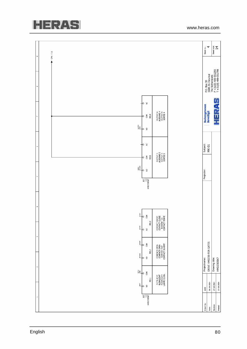
www.heras.com
English 80

www.heras.com
English 81

www.heras.com
English 82

www.heras.com
English 83

www.heras.com
English 84

www.heras.com
English 85

www.heras.com
English 86

www.heras.com
English 87

www.heras.com
English 88
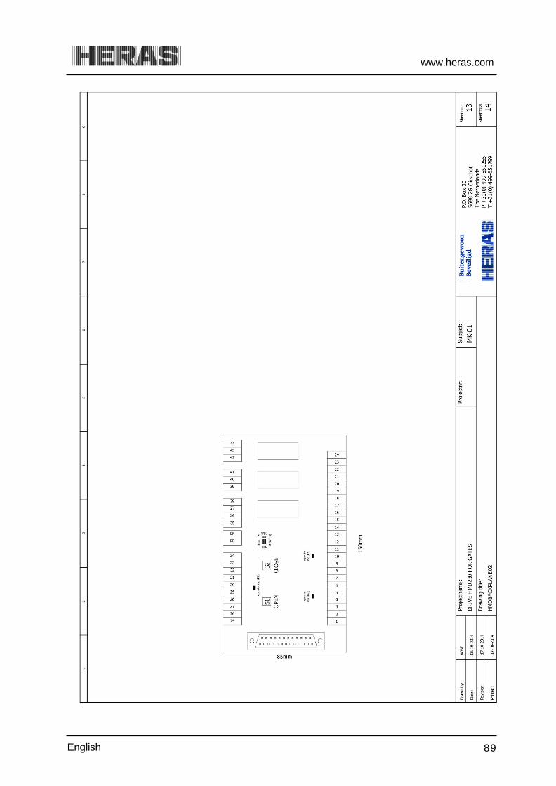
www.heras.com
English 89

www.heras.com
English 90

www.heras.com
English 91
Appendix D: ELECTRIC DIAGRAM IGD230
www.heras.com
English 92

www.heras.com
English 93

www.heras.com
English 94

www.heras.com
English 95

www.heras.com
English 96
www.heras.com
English 97
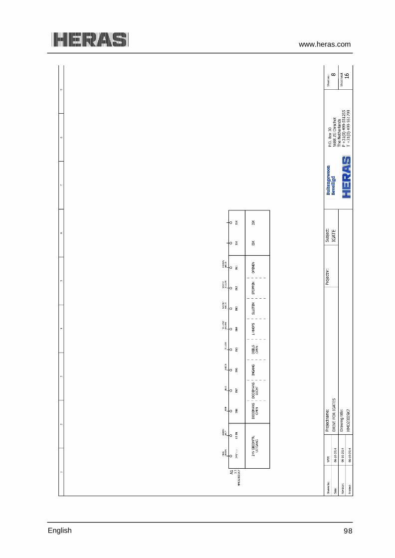
www.heras.com
English 98

www.heras.com
English 99

www.heras.com
English 100

www.heras.com
English 101
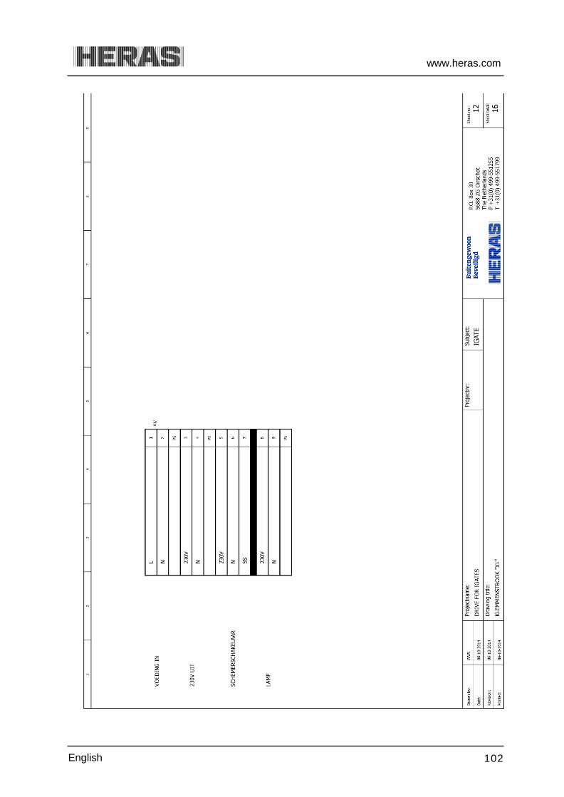
www.heras.com
English 102

www.heras.com
English 103

www.heras.com
English 104

www.heras.com
English 105

www.heras.com
English 106

www.heras.com
English 107

Local supplier stamp/ Lokal återförsäljare, stämpel
Related Documents


![User Guide...User. {{]}]} {}]}](https://static.cupdf.com/doc/110x72/60918ca14327954d24291644/-user-guide-user-.jpg)