Please visit www.hattelandtechnology.com for the latest electronic version of this manual. HD 16T30 MMC-xxx-xxxxxx - 15.6 inch Maritime Multi Computer HD 21T30 MMC-xxx-xxxxxx - 21.5 inch Maritime Multi Computer HD 24T30 MMC-xxx-xxxxxx - 23.8 inch Maritime Multi Computer HD 27T30 MMC-xxx-xxxxxx - 27.0 inch Maritime Multi Computer (where x=configurations/factory options) Series E - Maritime Multi Computer (MMC) Models USER MANUAL User Manual MMC Series E Updated: 24 Nov 2021 Doc Id: INB101505-1 (Rev 04) Created: 363 Approved: 6987

Welcome message from author
This document is posted to help you gain knowledge. Please leave a comment to let me know what you think about it! Share it to your friends and learn new things together.
Transcript
Please visit www.hattelandtechnology.com for the latest electronic version of this manual.
HD 16T30 MMC-xxx-xxxxxx - 15.6 inch Maritime Multi ComputerHD 21T30 MMC-xxx-xxxxxx - 21.5 inch Maritime Multi ComputerHD 24T30 MMC-xxx-xxxxxx - 23.8 inch Maritime Multi ComputerHD 27T30 MMC-xxx-xxxxxx - 27.0 inch Maritime Multi Computer
(where x=configurations/factory options)
Series E - Maritime Multi Computer (MMC) Models
USER MANUAL
User Manual MMC Series EUpdated: 24 Nov 2021 Doc Id: INB101505-1 (Rev 04)
Created: 363 Approved: 6987

Copyright © 2021 Hatteland Technology ASEikeskogvegen 52, N-5570 Aksdal, Norway.
All rights are reserved by Hatteland Technology AS. This information may not, in whole or in part, becopied, photocopied, reproduced, translated or reduced to any electronic medium or machine-
readable form without the prior written consent of Hatteland Technology AS. Review also: www.hattelandtechnology.com/hubfs/pdf/misc/doc100703-1_permission_to_create_user_manuals.pdf
The products described, or referenced, herein are copyrighted to the respective owners. The products may not be copied or duplicated in any way. This documentation contains proprietary
information that is not to be disclosed to persons outside the user’s company without prior written consent of Hatteland Technology AS.
The copyright notice appearing above is included to provide statutory protection in the event of unauthorized or unintentional public disclosure.
All other product names or trademarks are properties of their respective owners !
WARNING: This is a class A product. In a domestic environment this product may cause radio interferencein which case the user may be required to take adequate measures.
Statement above last revised 31 Jul. 2019
3IND100130-63
Contents .......................................................................................... 3Contents of package ............................................................................................................... 7
General ............................................................................................ 9IEC62368 policy - Introduction ............................................................................................. 10About this manual ..................................................................................................................11About Hatteland Technology ..................................................................................................11www.hattelandtechnology.com ..............................................................................................11Contact Information ...............................................................................................................11Maritime Multi Computer (MMC) Series E - Introduction ...................................................... 12Product Labeling ................................................................................................................... 13Touch screen products ......................................................................................................... 16
Installation ..................................................................................... 19General Installation Recommendations ................................................................................ 20First Things First! .................................................................................................................. 20Installation and mounting ...................................................................................................... 20Installation limitations ........................................................................................................... 21Ergonomics ........................................................................................................................... 23Cables .................................................................................................................................. 24
Cable Entries & Connectors (Marked area) ...................................................................... 24Maximum Cable Length .................................................................................................... 24
Housing / Terminal Block Connector Overview .................................................................... 25Panel Cutout / Console Mounting Bracket Kit - 15.6 inch ..................................................... 28Panel Cutout / Console Mounting Bracket Kit - 21.5, 23.8 and 27.0 inch ............................. 30Mounting Bracket, Table / Desktop / Ceiling - 15.6 inch ....................................................... 31Mounting Bracket, Table / Desktop / Ceiling - 21.5, 23.8 and 27.0 inch ............................... 33Physical Connections ........................................................................................................... 35Module Expansion Matrix ..................................................................................................... 39Factory Standards ................................................................................................................ 39COM Ports Numbering ........................................................................................................ 41
Operation ....................................................................................... 43User Controls ........................................................................................................................ 44
Specifications ............................................................................... 47Specifications - HD 16T30 MMC-xxx-xxxxxx ........................................................................ 48Specifications - HD 21T30 MMC-xxx-xxxxxx ........................................................................ 49Specifications - HD 24T30 MMC-xxx-xxxxxx ........................................................................ 50Specifications - HD 27T30 MMC-xxx-xxxxxx ........................................................................ 51
Contents
Contents
4IND100130-63
Specifications Factory Options................................................... 53Specifications - CAN Module with CO-Processor ................................................................. 54
ZIA0001310-B ................................................................................................................... 54Specifications - CAN Module with CO-Processor ................................................................. 55
ZIA0001310-SLCAN.......................................................................................................... 55Specifications - NMEA / IEC COM Module RS-422 / RS-485 .............................................. 56
PCA100293-1 .................................................................................................................... 56Specifications - Isolated Digital Input/Output Module ........................................................... 60
PCA100297-1 .................................................................................................................... 60Specifications - LAN Module ................................................................................................ 62
PCA100298-1 .................................................................................................................... 62Specifications - Isolated COM Module RS-232 .................................................................... 63
PCA100309-1 .................................................................................................................... 63Specifications - HD550N1 SDI M2 / HD550N1 HDV ............................................................ 64
Specifications Accessories ......................................................... 67Specifications - JH C01MF A-A ............................................................................................ 68Specifications - External Modules (USB) .............................................................................. 69
Technical Drawings ...................................................................... 71Technical Drawings - HD 16T30 MMC-xxx-xxxxxx ............................................................... 72
HW00 Model...................................................................................................................... 73Technical Drawings - HD 21T30 MMC-xxx-xxxxxx ............................................................... 74
HW00 Model...................................................................................................................... 75Technical Drawings - HD 24T30 MMC-xxx-xxxxxx ............................................................... 76
HW00 Model...................................................................................................................... 77Technical Drawings - HD 27T30 MMC-xxx-xxxxxx ............................................................... 78
HW00 Model...................................................................................................................... 79
Contents
5IND100130-63
Technical Drawings - Accessories .............................................. 81Technical Drawings - HD CMB SE1-A1 ................................................................................ 82
Console Mount Kit 15.6 inch ............................................................................................. 82P025485 (“Type A” Bracket) .............................................................................................. 84P025487 (“Type B” Bracket) .............................................................................................. 85
Technical Drawings - HD CMB SE1-B1 ................................................................................ 86Console Mount Kit 21.5 inch ............................................................................................. 86Console Mounting 21.5 inch .............................................................................................. 87Flush Mounting 21.5 inch .................................................................................................. 88
Technical Drawings - HD CMB SE1-B1 ................................................................................ 89Console Mount Kit 23.8 inch ............................................................................................. 89Console Mounting 23.8 inch .............................................................................................. 90Flush Mounting 23.8 inch .................................................................................................. 91
Technical Drawings - HD CMB SE1-B1 ................................................................................ 92Flush Mounting 27.0 inch .................................................................................................. 92Console Mounting 27.0 inch .............................................................................................. 93Flush Mounting 27.0 inch .................................................................................................. 94
Technical Drawings - HD TMB SE1-A1 ................................................................................ 95Desktop/Table Mounting Bracket 15.6 inch ....................................................................... 95
Technical Drawings - HD TMB SE1-B1 ................................................................................ 96Desktop/Table Mounting Bracket 21.5/23.8/27.0 inch ....................................................... 96
Technical Drawings - External Modules (USB) ..................................................................... 97
Contents
6IND100130-63
Appendixes ................................................................................... 99IoT (Internet of Things) Overview ....................................................................................... 100SSD Selection Guide .......................................................................................................... 101ATX / AT Power Modes ....................................................................................................... 105Trusted Platform Module (TPM) ........................................................................................ 106Secure Boot ....................................................................................................................... 107Choose Boot Device .......................................................................................................... 107Battery Status and Alarm ................................................................................................... 108LAN Teaming ..................................................................................................................... 109Reading internal temperature .............................................................................................111Using the eMMC as a backup/recovery device when SSD is used ....................................111Install Operating System (OS) ............................................................................................111Install Microsoft® Windows® 10 with recovery option .........................................................112Trouble-shooting ..................................................................................................................116Operating System Recovery (tool) .....................................................................................116How to activate Windows Recovery Environment on OS Drive ........................................ 120RTC Timer (Apollolake) - User Guide ................................................................................ 121BIOS Default Settings Overview ......................................................................................... 131WatchDog Timer function ................................................................................................... 138Pinout Assignments ............................................................................................................ 139IEC62368 policy for Hatteland Technology products .......................................................... 143Basic Trouble-shooting ....................................................................................................... 145Declaration of Conformity ................................................................................................... 146Return Of Goods Information ............................................................................................. 147General Terms and Conditions ........................................................................................... 148Pixel Defect Policy .............................................................................................................. 149Parts and Recycling ............................................................................................................ 150Notes .................................................................................................................................. 151Revision History .................................................................................................................. 153
7IND100131-44
Contents of package
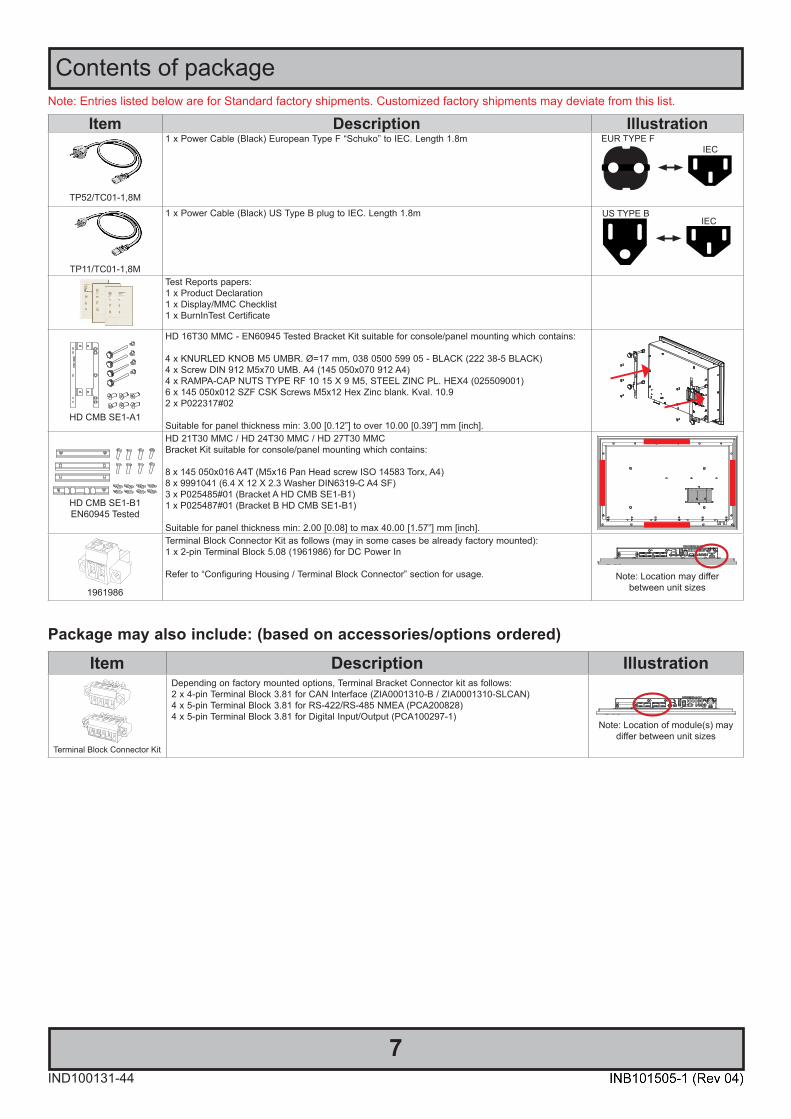
Item Description Illustration
TP52/TC01-1,8M
1 x Power Cable (Black) European Type F “Schuko” to IEC. Length 1.8m EUR TYPE FIEC
TP11/TC01-1,8M
1 x Power Cable (Black) US Type B plug to IEC. Length 1.8m US TYPE BIEC
Test Reports papers:1 x Product Declaration1 x Display/MMC Checklist1 x BurnInTest Certificate
HD CMB SE1-A1
HD 16T30 MMC - EN60945 Tested Bracket Kit suitable for console/panel mounting which contains:
4 x KNURLED KNOB M5 UMBR. Ø=17 mm, 038 0500 599 05 - BLACK (222 38-5 BLACK) 4 x Screw DIN 912 M5x70 UMB. A4 (145 050x070 912 A4)4 x RAMPA-CAP NUTS TYPE RF 10 15 X 9 M5, STEEL ZINC PL. HEX4 (025509001)6 x 145 050x012 SZF CSK Screws M5x12 Hex Zinc blank. Kval. 10.92 x P022317#02
Suitable for panel thickness min: 3.00 [0.12”] to over 10.00 [0.39”] mm [inch].
HD CMB SE1-B1EN60945 Tested
HD 21T30 MMC / HD 24T30 MMC / HD 27T30 MMC Bracket Kit suitable for console/panel mounting which contains:
8 x 145 050x016 A4T (M5x16 Pan Head screw ISO 14583 Torx, A4) 8 x 9991041 (6.4 X 12 X 2.3 Washer DIN6319-C A4 SF)3 x P025485#01 (Bracket A HD CMB SE1-B1) 1 x P025487#01 (Bracket B HD CMB SE1-B1)
Suitable for panel thickness min: 2.00 [0.08] to max 40.00 [1.57”] mm [inch].
1961986
Terminal Block Connector Kit as follows (may in some cases be already factory mounted):1 x 2-pin Terminal Block 5.08 (1961986) for DC Power In
Refer to “Configuring Housing / Terminal Block Connector” section for usage. Note: Location may differbetween unit sizes
Note: Entries listed below are for Standard factory shipments. Customized factory shipments may deviate from this list.
Item Description Illustration
Terminal Block Connector Kit
Depending on factory mounted options, Terminal Bracket Connector kit as follows:2 x 4-pin Terminal Block 3.81 for CAN Interface (ZIA0001310-B / ZIA0001310-SLCAN)4 x 5-pin Terminal Block 3.81 for RS-422/RS-485 NMEA (PCA200828)4 x 5-pin Terminal Block 3.81 for Digital Input/Output (PCA100297-1)
Note: Location of module(s) may differ between unit sizes
Package may also include: (based on accessories/options ordered)

8
This page left intentionally blank

9
General
10IND100078-81
General
IEC62368 policy - Introduction
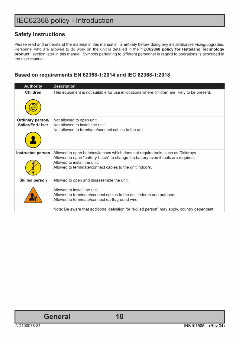
Safety InstructionsPlease read and understand the material in this manual in its entirety before doing any installation/servicing/upgrades. Personnel who are allowed to do work on the unit is detailed in the “IEC62368 policy for Hatteland Technology product” section later in this manual. Symbols pertaining to different personnel in regard to operations is described in the user manual.
Based on requirements EN 62368-1:2014 and IEC 62368-1:2018
Authority DescriptionChildren This equipment is not suitable for use in locations where children are likely to be present.
Ordinary person/Sailor/End-User
Not allowed to open unit. Not allowed to install the unit. Not allowed to terminate/connect cables to the unit.
Instructed person Allowed to open hatches/latches which does not require tools, such as Disktrays. Allowed to open "battery-hatch" to change the battery even if tools are required.Allowed to install the unit.Allowed to terminate/connect cables to the unit indoors.
Skilled person Allowed to open and disassemble the unit.
Allowed to install the unit.Allowed to terminate/connect cables to the unit indoors and outdoors.Allowed to terminate/connect earth/ground wire. Note: Be aware that additional definition for “skilled person” may apply, country dependent.

11
Hatteland Technology AS
IND100077-1
General
About this manualThe manual contains electrical, mechanical and input/output signal specifications. All specifications in this manual, due to manufacturing, new revisions and approvals, are subject to change without notice. However, the last updated and revision date of this manual are shown both on the frontpage and also in the “Revision History” chapter. This user manual is a standard/general manual that applies to all variations of its product family, i.e. deviation from actual configuration may exist.
About Hatteland TechnologyHatteland Technology is the leading technology provider of specialized display and computer products, delivering high quality, unique and customized solutions to the international maritime, naval and industrial markets.
The company represents innovation and quality to the system integrators worldwide. Effective quality assurance and investment in sophisticated in-house manufacturing methods and facilities enable us to deliver Type Approved and Mil tested products. Our customer-oriented approach, technical knowledge and dedication to R&D, makes us a trusted and preferred supplier of approved solutions, which are backed up by a strong service network.
www.hattelandtechnology.comYou will find our website full of useful information to help you make an informed choice as to the right product for your needs. You will find detailed product descriptions and specifications for the entire range on Displays, Computers,Panel Computers and Military solutions as well as the range of supporting accessories. The site carries a wealth ofinformation regarding our product testing and approvals in addition to company contact information for our variousoffices around the world, the global service locations and the technical support centre, all ensuring the best possiblesupport wherever you, or your vessel, may be in the world. Contact Information
Head office, Aksdal / Norway:Hatteland Technology AS
Eikeskogvegen 52N-5570 Aksdal, Norway
Switchboard:Tel: +47 4814 2200
Sales office, Frankfurt / Germany:Hatteland Technology GmbHWerner Heisenberg Strasse 2,
D-63263 Neu-Isenburg, Germany
Elke Freisens: Tel: +49 173 6174753
Sales office, Oslo / Norway:Hatteland Technology AS
Strandveien 35 N-1366 Lysaker
Norway
Switchboard:Tel: +47 4814 2200
Sales office, Aix-en-Provence / France:Hatteland Technology SAS
Actimart- 1140, rue Ampère, CS 80544 13594 Aix-en-Provence, Cedex 3
France
Mehdi Bounoua (Sales Director Europe, Middle East & Africa): Tel : +33 6 88 33 64 93
Sales office, Vista / USA:Hatteland Technology Inc450 South Melrose Drive,
Suite #107Vista, CA 92081
USA
Donna Pallonetti: Tel: +1 858-282-0659Fax: +1 858-408-1834
For an up-2-date list, please visit https://www.hattelandtechnology.com/contact
12
Panel Computers Series E
IND101057-23
General
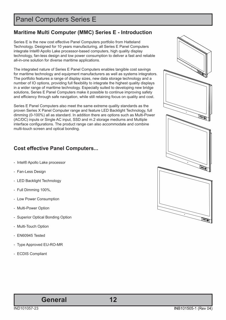
Maritime Multi Computer (MMC) Series E - IntroductionSeries E is the new cost effective Panel Computers portfolio from Hatteland Technology. Designed for 10 years manufacturing, all Series E Panel Computers integrate Intel® Apollo Lake processor-based computers, high quality display technology, fan-less design and low power consumption to deliver a fast and reliableall-in-one solution for diverse maritime applications.
The integrated nature of Series E Panel Computers enables tangible cost savingsfor maritime technology and equipment manufacturers as well as systems integrators. The portfolio features a range of display sizes, new data storage technology and a number of IO options, providing full flexibility to integrate the highest quality displays in a wider range of maritime technology. Especially suited to developing new bridge solutions, Series E Panel Computers make it possible to continue improving safety and efficiency through safe navigation, while still retaining focus on quality and cost.
Series E Panel Computers also meet the same extreme quality standards as the proven Series X Panel Computer range and feature LED Backlight Technology, full dimming (0-100%) all as standard. In addition there are options such as Multi-Power (AC/DC) inputs or Single AC input, SSD and m.2 storage mediums and Multiple interface configurations. The product range can also accommodate and combine multi-touch screen and optical bonding.
Cost effective Panel Computers...
- Intel® Apollo Lake processor
- Fan-Less Design
- LED Backlight Technology
- Full Dimming 100%,
- Low Power Consumption
- Multi-Power Option
- Superior Optical Bonding Option
- Multi-Touch Option
- EN60945 Tested
- Type Approved EU-RO-MR
- ECDIS Compliant
13IND100077-202
Product Labeling
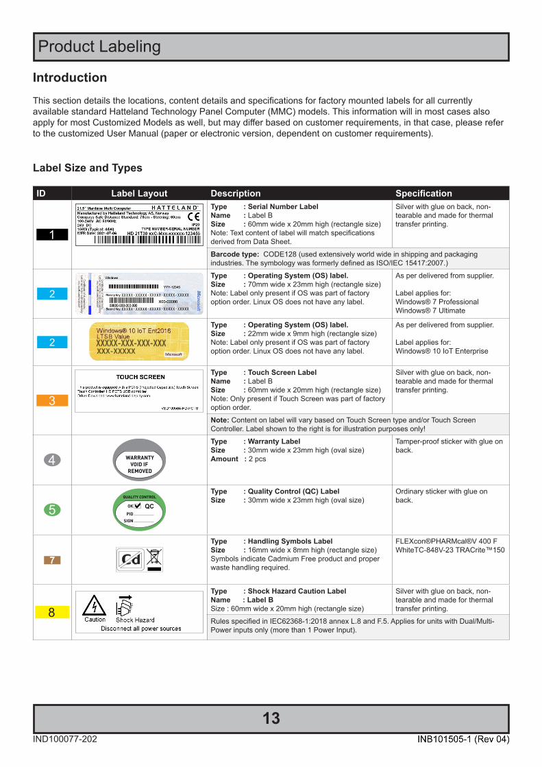
IntroductionThis section details the locations, content details and specifications for factory mounted labels for all currentlyavailable standard Hatteland Technology Panel Computer (MMC) models. This information will in most cases alsoapply for most Customized Models as well, but may differ based on customer requirements, in that case, please refer to the customized User Manual (paper or electronic version, dependent on customer requirements).
Label Size and Types
ID Label Layout Description SpecificationType : Serial Number LabelName : Label BSize : 60mm wide x 20mm high (rectangle size)Note: Text content of label will match specifications derived from Data Sheet.
Silver with glue on back, non-tearable and made for thermaltransfer printing.
Barcode type: CODE128 (used extensively world wide in shipping and packagingindustries. The symbology was formerly defined as ISO/IEC 15417:2007.)
Type : Operating System (OS) label. Size : 70mm wide x 23mm high (rectangle size)Note: Label only present if OS was part of factoryoption order. Linux OS does not have any label.
As per delivered from supplier.
Label applies for:Windows® 7 ProfessionalWindows® 7 Ultimate
Type : Operating System (OS) label. Size : 22mm wide x 9mm high (rectangle size)Note: Label only present if OS was part of factoryoption order. Linux OS does not have any label.
As per delivered from supplier.
Label applies for:Windows® 10 IoT Enterprise
Type : Touch Screen LabelName : Label BSize : 60mm wide x 20mm high (rectangle size)Note: Only present if Touch Screen was part of factory option order.
Silver with glue on back, non-tearable and made for thermaltransfer printing.
Note: Content on label will vary based on Touch Screen type and/or Touch ScreenController. Label shown to the right is for illustration purposes only!
Type : Warranty LabelSize : 30mm wide x 23mm high (oval size)Amount : 2 pcs
Tamper-proof sticker with glue on back.
Type : Quality Control (QC) LabelSize : 30mm wide x 23mm high (oval size)
Ordinary sticker with glue on back.
Type : Handling Symbols LabelSize : 16mm wide x 8mm high (rectangle size)Symbols indicate Cadmium Free product and proper waste handling required.
FLEXcon®PHARMcal®V 400 F WhiteTC-848V-23 TRACrite™150
Type : Shock Hazard Caution LabelName : Label BSize : 60mm wide x 20mm high (rectangle size)
Silver with glue on back, non-tearable and made for thermaltransfer printing.
Rules specified in IEC62368-1:2018 annex L.8 and F.5. Applies for units with Dual/Multi-Power inputs only (more than 1 Power Input).
14
Product Labeling
IND100077-202
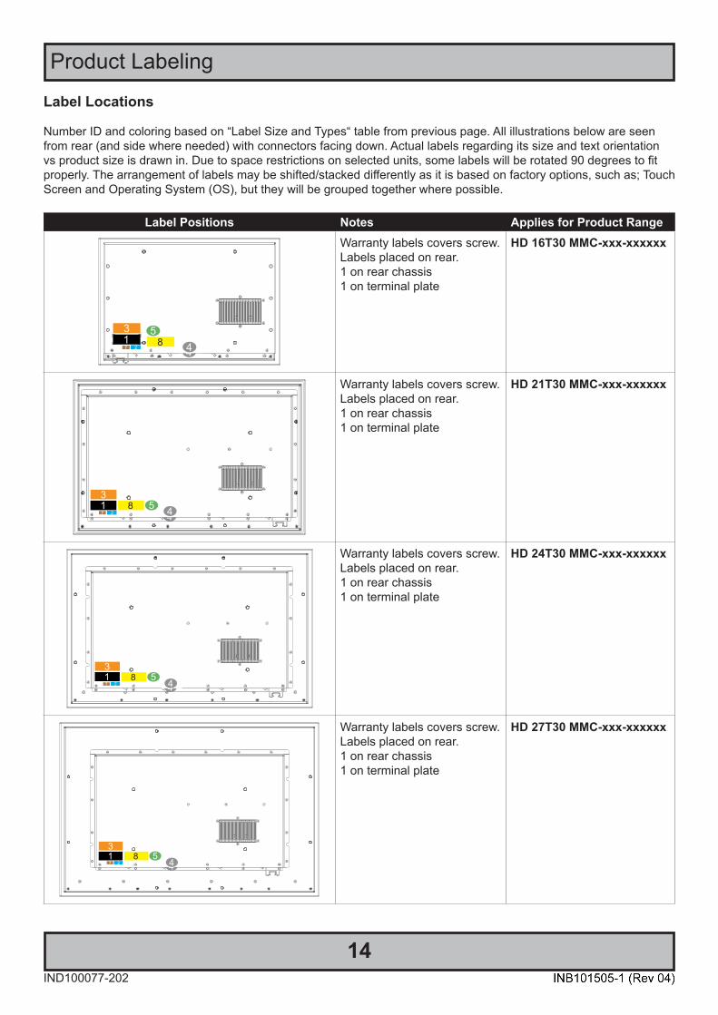
Label Locations
Number ID and coloring based on “Label Size and Types“ table from previous page. All illustrations below are seen from rear (and side where needed) with connectors facing down. Actual labels regarding its size and text orientation vs product size is drawn in. Due to space restrictions on selected units, some labels will be rotated 90 degrees to fit properly. The arrangement of labels may be shifted/stacked differently as it is based on factory options, such as; Touch Screen and Operating System (OS), but they will be grouped together where possible.
Label Positions Notes Applies for Product RangeWarranty labels covers screw. Labels placed on rear.1 on rear chassis1 on terminal plate
HD 16T30 MMC-xxx-xxxxxx
Warranty labels covers screw. Labels placed on rear.1 on rear chassis1 on terminal plate
HD 21T30 MMC-xxx-xxxxxx
Warranty labels covers screw. Labels placed on rear.1 on rear chassis1 on terminal plate
HD 24T30 MMC-xxx-xxxxxx
Warranty labels covers screw. Labels placed on rear.1 on rear chassis1 on terminal plate
HD 27T30 MMC-xxx-xxxxxx
15
Product Labeling
IND100077-203
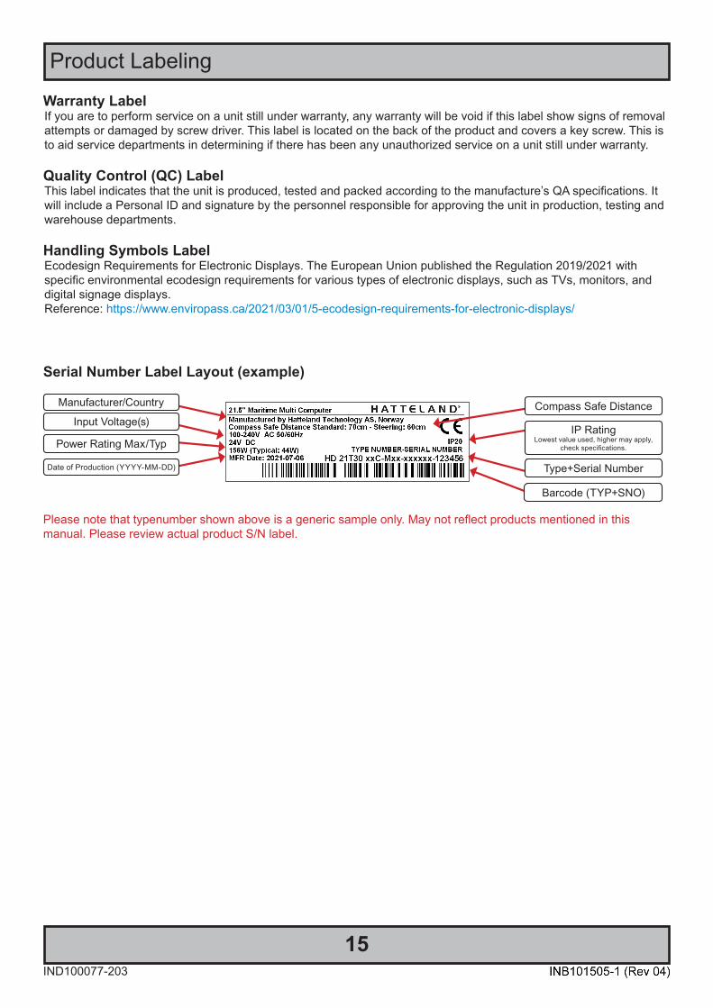
Serial Number Label Layout (example)
Warranty LabelIf you are to perform service on a unit still under warranty, any warranty will be void if this label show signs of removal attempts or damaged by screw driver. This label is located on the back of the product and covers a key screw. This is to aid service departments in determining if there has been any unauthorized service on a unit still under warranty.
Quality Control (QC) LabelThis label indicates that the unit is produced, tested and packed according to the manufacture’s QA specifications. It will include a Personal ID and signature by the personnel responsible for approving the unit in production, testing andwarehouse departments.
Handling Symbols LabelEcodesign Requirements for Electronic Displays. The European Union published the Regulation 2019/2021 withspecific environmental ecodesign requirements for various types of electronic displays, such as TVs, monitors, and digital signage displays. Reference: https://www.enviropass.ca/2021/03/01/5-ecodesign-requirements-for-electronic-displays/
Please note that typenumber shown above is a generic sample only. May not reflect products mentioned in this manual. Please review actual product S/N label.
Manufacturer/Country
Input Voltage(s)
Type+Serial Number
Barcode (TYP+SNO)
Power Rating Max/Typ
Date of Production (YYYY-MM-DD)
Compass Safe Distance
IP RatingLowest value used, higher may apply,
check specifications.

16IND100110-12
Touchscreen
Introduction to products with touch screen (factory option)Nearly all of our products with touch screen use Projected Capacitive Touch screen (PCTS), widely used with greatsuccess on mobile phones and typical pad devices. PCTS can be equally effective also for marine applications.One of the advantages of PCTS is that it has features seen in both resistive and surface capacitive touch screen technologies.
Multitouch is defined as the ability to recognize two or more simultaneous touch points. Using projected capacitivetechnology allows us to create a more intuitive form of human-device interaction. Touch interface gestures, supported by projected capacitive sensors, can simplify the interface and provide an intuitive user experience that goes beyond the typical "button replacement" found in most simple touch interfaces.
Please review the appropriate Product Datasheet (in this manual) to determine if PCTS are supported and/or itsadvanced features of additional touch methods (example Tactor and Active Stylus Pen) are available.
The technical benefits of PCTS are:- Very good optical performance (same as surface capacitive)
- Environmentally strong, the touch sensor is inside the product (better than both surface capacitive and resistive)
- Supports Multitouch (Newer Operating System (OS) required in most cases.
- Excellent readability - light transmission of up to 91% through a standard sensor
- Stability - no drift, therefore no recalibration is required
- Pointing device - works with gloved and ungloved finger
- Resistance to contamination - by harsh cleaning fluids and other noxious substances
- Communicates via USB to external computer or internally
Comparisons between general Touch Technologies used by Hatteland Technology:Technology Optical Performance Gloves Water Durability Multitouch Stylus Objects (Tactor)Analog Resistive - - + + + + - - - - -Surface Capacitive + + - - - + - - - -Projected Capacitive + + + + * + + + + + + + +
*Projected Capacitive (PCTS) / Water: Touch Screen Glass Surface can withstand drip and direct rain, but expect reduced capability, detection and performance if units are exposed to these factors while powered. Hatteland Technology recommends protecting the unit from direct rain or drips ifcritical touch operations are to be performed. Take necessary steps (if detected or suspected) within the installation environment to prevent accidental touch gestures or presses not performed intentionally by a human operator.
Touch screen products
17Touch screenIND100110-20
Touch Screen DriversAll units with Touch Screens are automatically detected by the Operating System via HID. There is no need to install additional Third-Party touch screen drivers.
Microsoft® Windows® 10 IoT - Please use Windows® Generic HID driver, no specific driver needed to use multi-touch.
Linux- Please use Linux Generic Touch driver. Use kernel 4.10 or later.
If you experience any deviation in the touch input accuracy, consider re-calibrating the touch screen for your system.Please use the standard Operating System functionality to calibrate.
Example for Microsoft® Windows® 10 IoT: 1.Open Control Panel.2.Click on Hardware and Sound.3.Under “Tablet PC Settings”, click the Calibrate the screen for pen or touch input link.4.Under “Display options”, select the display (if applicable).5.Click the Calibrate button.6.Select the Touch input option.
Note for units equipped with an PCTS (Projected Capacitive) Touch Screen:Maritime Multi Computer (MMC, Panel Computer) uses internal USB connection and can be controlled by the Operating System (OS). So, in order to clean the glass without any touch screen movement being detected, you either have to shut down the Operating System (either via customized functions from within applications or by touching the Power On/Off symbol) to make sure the unit has been shut down before attempting to clean the glass surface.
To learn more about how to properly clean glass surfaces, review the “Ergonomics” section in the “General Installation Recommendations” chapter later in this manual.
Touch screen products

18
This page left intentionally blank

19
Installation

20InstallationIND100078-70
General Installation Recommendations
First Things First!
Applies for non-bonded product only: If exposed to humidityin combination with temperature variations, product mightshow condensation on the glass (inside and outside).
Inside condensation can be removed by power on theproduct and set brightness to 100%. During minutes theinternal temperature rise will remove condensation.
Humidity Exposure Notice!yy
ATTENTION!
IND100148-5 - Rev 05
To prevent damage to chassis and glass, pleasereview the illustrations ! Place horizontally on a smooth and clean surface (table with cloth) Do not stress the corners, nor place it on a coarse and/or dirty surface
CORRECT HANDLING! WRONG HANDLING!CORRECT HANDLING! WRONG HANDLING!
Installation and mounting1. Most of our products are intended for various methods of installation or mounting (panel mounting, bracket mounting, ceiling/wall, console mounting etc.); for details, please see the relevant mechanical drawings.
2. Adequate ventilation is a necessary prerequisite for the life of the product. The air inlet and outlet openings must definitely be kept clear; coverings which restrict ventilation are not permissible.
3. Generally, do not install the unit in a horizontal position (laying down), as this will cause heat to build up inside the unit which will damage the LCD Panel. To prevent this problem we recommend installing the unit in a vertical position (±30 degrees) to improve the airflow through the unit.
4. To further improve the thermal situation we recommend using forced air passing by the product. In some cases, convection based cooling can create “heat zones” around the product. This may be required in high temperature applications and also when there is reason to expect temperature problems due to non-optimal way of mounting.
5. Exposure to extreme direct sunlight can cause a considerable increase in the temperature of the unit, and might under certain circumstances lead to excessive temperature. This point should already be taken into consideration when the bridge equipment is being planned (sun shades, distance from the windows, ventilation, etc.). To maximize product life, it is recommended using Hatteland Technology's UV Sun Covers when the product is not in use. Long term direct sun exposure might have cosmetic impacts on the product.
6. Space necessary for ventilation, for cable inlets, for the operating procedures and for maintenance, must be provided.
7. If the push buttons of the product are not illuminated, an external, dimmable illumination (IEC 60945 Ed. 4, 4.2.2.3, e.g. Goose neck light) is required for navigational use. The illumination shall be free from glare and adjustable to extinction.
21
General Installation Recommendations
InstallationIND100078-70
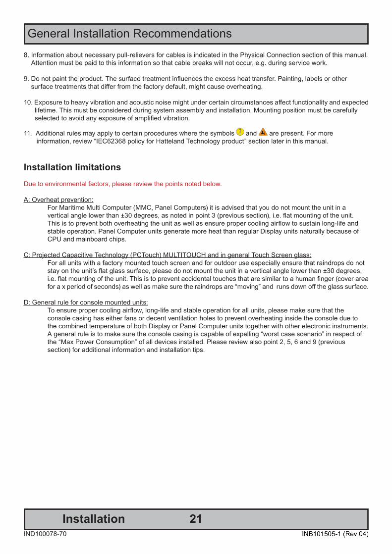
8. Information about necessary pull-relievers for cables is indicated in the Physical Connection section of this manual. Attention must be paid to this information so that cable breaks will not occur, e.g. during service work.
9. Do not paint the product. The surface treatment influences the excess heat transfer. Painting, labels or other surface treatments that differ from the factory default, might cause overheating.
10. Exposure to heavy vibration and acoustic noise might under certain circumstances affect functionality and expected lifetime. This must be considered during system assembly and installation. Mounting position must be carefully selected to avoid any exposure of amplified vibration.
11. Additional rules may apply to certain procedures where the symbols and are present. For more information, review “IEC62368 policy for Hatteland Technology product” section later in this manual.
Installation limitationsDue to environmental factors, please review the points noted below.
A: Overheat prevention: For Maritime Multi Computer (MMC, Panel Computers) it is advised that you do not mount the unit in a vertical angle lower than ±30 degrees, as noted in point 3 (previous section), i.e. flat mounting of the unit. This is to prevent both overheating the unit as well as ensure proper cooling airflow to sustain long-life and stable operation. Panel Computer units generate more heat than regular Display units naturally because of CPU and mainboard chips.
C: Projected Capacitive Technology (PCTouch) MULTITOUCH and in general Touch Screen glass: For all units with a factory mounted touch screen and for outdoor use especially ensure that raindrops do not stay on the unit’s flat glass surface, please do not mount the unit in a vertical angle lower than ±30 degrees, i.e. flat mounting of the unit. This is to prevent accidental touches that are similar to a human finger (cover area for a x period of seconds) as well as make sure the raindrops are “moving” and runs down off the glass surface.
D: General rule for console mounted units: To ensure proper cooling airflow, long-life and stable operation for all units, please make sure that the console casing has either fans or decent ventilation holes to prevent overheating inside the console due to the combined temperature of both Display or Panel Computer units together with other electronic instruments. A general rule is to make sure the console casing is capable of expelling “worst case scenario” in respect of the “Max Power Consumption” of all devices installed. Please review also point 2, 5, 6 and 9 (previous section) for additional information and installation tips.

22
General Installation Recommendations
InstallationIND100078-70
General mounting instructions1. The useful life of the components of all Electronics Units generally decreases with increasing ambient temperature; it is therefore advisable to install such units in air-conditioned rooms. If there are no such facilities these rooms must at least be dry, adequately ventilated and kept at a suitable temperature in order to prevent the formation of condensation inside the display unit.
2. With most Electronic Units, cooling takes place via the surface of the casing. The cooling must not be impaired by partial covering of the unit or by installation of the unit in a confined cabinet.
3. In the area of the wheel house, the distance of each electronics unit from the magnetic standard compass or the magnetic steering compass must not be less than the permitted magnetic protection distance. This distance is measured from the centre of the magnetic system of the compass to the nearest point on the corresponding unit concerned.
4. Units which are to be used on the bridge wing must be installed inside the “wing control console” protected against the weather. In order to avoid misting of the viewing screen, a 25 ... 50 W console-heating (power depending on the volume) is recommended.
5. When selecting the site of a display unit, the maximum cable lengths have to be considered.
6. When a product is being installed, the surface base or bulkhead must be checked to ensure that it is flat in order to avoid twisting of the unit when the fixing screws are tightened, because such twisting would impair mechanical functions. Any unevenness should be compensated for by means of spacing-washers.
7. Products with AC input shall be grounded to protective Earth (Safety Ground) when necessary via the bolt (usually on terminal plate) available on the product. Products with DC input shall be grounded to protective Earth (Safety Ground) via the bolt (usually on terminal plate) available on the product. A shorter and thicker cable gives better grounding. A 6mm² is recommended, but a 4mm² or even 2.5mm² can be used for this purpose.
8. Transportation damage, even if apparently insignificant at first glance, must immediately be examined and be reported to the freight carrier. The moment of setting-to-work of the equipment is too late, not only for reporting the damage but also for the supply of replacements.
9. The classification is only valid for approved mounting brackets provided by Hatteland Technology. The unit shall be mounted stand-alone without any devices or loose parts placed at or nearby the unit. Any other type of mounting might require test and re-classification.
10. Additional rules may apply to certain procedures where the symbols and are present. For more information, review “IEC62368 policy for Hatteland Technology product” section later in this manual.

23
General Installation Recommendations
InstallationIND100078-70
Ergonomics1. The front surface of the display glass has an anti-reflective (AR) coating which can be scratched and damaged with improper cleaning. It is recommended using only 90+% pure Isopropyl alcohol (Isopropanol) and a soft fabric cloth for this first cleaning. Fold a cloth into a small pad, dampen the cloth with alcohol, and wipe the glass from one edge to the other in one direction with one continuous motion. The product glass will require cleaning as needed. The soft cloth & alcohol wipe is recommended to clean fingerprints and oils off the glass. Water stains (including coffee, tea & coke) should be first cleaned off the glass with a soft fabric cloth wet with water, immediately followed with wiping using an alcohol wetted cloth.
2. Adjust the unit height so that the top of the screen is at or below eye level. Your eyes should look slightly downwards when viewing the middle of the screen.
3. Adjust screen inclination to allow the angle of gaze to remain at the centre of the screen approximately perpendicular to the line of gaze.
4. When products are to be operated both from a sitting position and from a standing position, a screen inclination of about 30° to 40° (from a vertical plane) has turned out to be favourable.
5. The brightness of displays is limited. Sunlight passing directly through the bridge windows - or its reflection - which fall upon the screen workplaces must be reduced by suitable means (negatively inclined window surfaces, venetian blinds, distance from the windows, dark colouring of the deckhead). However, units can be offered with optical enhanced technology and/or High Bright panels to reduce reflections and are viewable in direct sun light, but as a general rule the units at the bridge wing area are recommended to be installed or mounted by suitable alignment or bulkhead / deckhead mounting in such a way that reflections of light from the front pane of the display are not directed into the observer’s viewing direction.
6. The use of ordinary commercial filter plates or filter films is not permitted for items of equipment that require approval (by optical effects, “aids” of that kind can suppress small radar targets, for example).
7. For ECDIS applications, the minimum recommended viewing distance are as follows: (IEC62288, Part 7.5 Screen resolution)
15.6 inch = 616mm 21.5 inch = 852mm 23.8 inch = 943mm 27.0 inch = 1070mm

24
General Installation Recommendations
InstallationIND100078-70
CablesUse only high quality shielded signal cables. Cable Entries & Connectors (Marked area)Illustration below for smallest/largest sizes only.
Bottom View Back View
Maximum Cable Length
Any cable should generally be kept as short as possible to provide a high quality input/output. The maximum signal cable length will depend not only on the signal resolution and frequency, but also on the quality of the signal output from the computer/radar.

25
General Installation Recommendations
InstallationIND100210-42
Housing / Terminal Block Connector OverviewHousing / Terminal Block connectors are available in different sizes (example 2-pin, 4-pin, 5-pin) which plug into theconnector area of the unit. They are mounted by factory default and delivered with the unit. The housing / terminal block connectors have steering rails, which ensures that it can not be mounted wrong. The color of these connectors may vary between black, green and orange depending on manufacturer. You may use approved equivalents of these connectors, but note that the warranty will be void if any damage would occur to either the unit’s original PCB terminal socket connector or inside the unit (electronic components, boards etc.). The table below is applicable for any Series X products, such as Display and Panel Computers, including newer type of Stand-Alone Computers.
Illustration Pins Manufacturer Details Connector used for module
5-pin MC 1,5/ 5-STF-3,81Screwdriver: SZS 0,4X2,5mm VDE, slot-headed.
Tightening torque min. 0.22 Nm.Tightening torque max 0.25 Nm.
• RS-422 / RS-485 NMEA (PCA200828-1 / PCA100293-1 Q170 IO)• Digital Input/Output (PCA100297-1 / Q170 IO)
Identifi ed on Hatteland Technology product datasheet as:“Terminal Block 3.81”
2-pin MSTB 2,5/ 2-STF-5,08 BK
Screwdriver: SZS 0,6x3,5, slot-headed.Tightening torque min. 0.5 Nm.Tightening torque max 0.6 Nm.
• DC Power IN (24VDC) - Dual Input
Identifi ed on Hatteland Technology product datasheet as:“Terminal Block 5.08”
4-pin BCZ 3.81/04/180F SN BK BX
Screwdriver: 0.4x2.5mm DIN 5264.Tightening torque min.. 0.2 Nm.Tightening torque max. 0.25 Nm.
• CAN Interface (ZIA0001310-B / ZIA0001310-SLCAN)
Identifi ed on Hatteland Technology product datasheet as:“Terminal Block 3.81”
26
General Installation Recommendations
InstallationIND100210-42
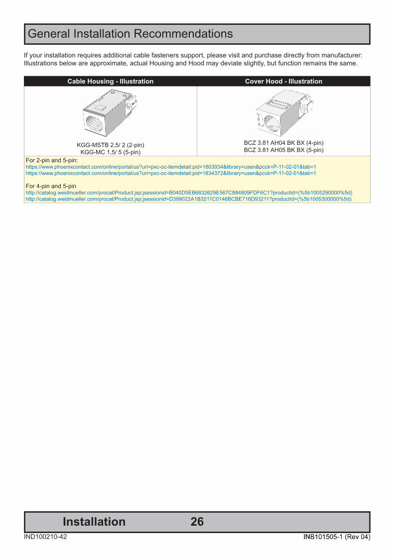
If your installation requires additional cable fasteners support, please visit and purchase directly from manufacturer:Illustrations below are approximate, actual Housing and Hood may deviate slightly, but function remains the same.
Cable Housing - Illustration Cover Hood - Illustration
KGG-MSTB 2,5/ 2 (2-pin)KGG-MC 1,5/ 5 (5-pin)
BCZ 3.81 AH04 BK BX (4-pin)BCZ 3.81 AH05 BK BX (5-pin)
For 2-pin and 5-pin:https://www.phoenixcontact.com/online/portal/us?uri=pxc-oc-itemdetail:pid=1803934&library=usen&pcck=P-11-02-01&tab=1https://www.phoenixcontact.com/online/portal/us?uri=pxc-oc-itemdetail:pid=1834372&library=usen&pcck=P-11-02-01&tab=1
For 4-pin and 5-pinhttp://catalog.weidmueller.com/procat/Product.jsp;jsessionid=B040D5EB6832629E567C884809FDF6C1?productId=(%5b1005290000%5d)http://catalog.weidmueller.com/procat/Product.jsp;jsessionid=D399022A1B3211C0146BCBE716D93211?productId=(%5b1005300000%5d)

27
General Installation Recommendations
InstallationIND100210-42
Configuring Housing / Terminal Block connectorsBelow is a brief illustration that might be useful during configuration and installation of such connectors. You will need suitable pre-configured cable(s) and tools to configure the connector(s) and cable(s) that are present in yourinstallation environment. Below is a sample procedure for a 2-pin DC power connector. The procedure is the same for other connectors of this type as listed in table above. Unit used as illustration below is for reference only.
FIG 5
FIG 1FIG 4 FIG 6
FIG 2FIG 3
Requires assembly. It is expected that the technician has experience in electronics and assembling cables and connectors.
Warning: Do not connect or disconnect cables/connectors to the unit’s connector while the unit is powered on. Failure to do so may result indamaged electronics.
FIG 1: Unscrew (from top) or make sure that the screw terminal is fully open, so you can secure the inserted cables correctly to the loose housing connector (it may already be plugged into the unit as per factory installation).
FIG 2: Strip carefully the insulation from the cable to expose the wire(s) inside.
FIG 3: Ensure that the wire(s) is without any loose threads to ensure good connection.
FIG 4: Insert cables* (from front) and screw / secure the cables by turning the screw on top of the housing to secure the cables properly. Check that the cables are firmly in place and do not appear loose or fall out when pulling gently.
*Note: Required polarization verification (for instance -/+ for DC power input) should conform with the markings on the connector area of the unit. Ignoring the markings on the unit or its add-on modules might damage the unit and/or external equipment in which end, warranty will be void.
FIG 5: Plug the housing into the appropriate connector area of the unit (glass should be facing down) and check again that the cables secured conform with the markings on the connector area of the unit. Finalize the installation byfastening the screws located in front on each side of the housing connector (FIG 6).
Connector / Function Recommended Cable Thickness2-pin DC Power Input (Terminal Block 5.08) Minimum 20 AWG - Maximum 18 AWG4-pin CAN (Terminal Block 3.81) Minimum 22 AWG - Maximum 20 AWG5-pin NMEA COM (Terminal Block 3.81) Minimum 22 AWG - Maximum 18 AWG5-pin DIO (Terminal Block 3.81) Minimum 22 AWG - Maximum 18 AWG

28InstallationIND100078-71
Installation Procedures
Panel Cutout / Console Mounting Bracket Kit - 15.6 inchYou need: Hex tool (5mm), 1 pcs of HD CMB SE1-A1 Kit (included in delivery).
4 pcs KNURLED KNOB M5 UMBR. Ø=17 mm, 038 0500 599 05 - BLACK (222 38-5 BLACK)
4 pcs Screw DIN 912 M5x70 UMB. A4 (145 050x070 912 A4)
4 pcs RAMPA-CAP NUTS TYPE RF 10 15 X 9 M5, STEEL ZINC PL. HEX4 (025509001)
6 pcs 145 050x012 SZF CSK Screws M5x12 Hex Zinc blank. Kval. 10.9
2 pcs P022317#02
Attention: A suitable pre-cut panel cutout should be made prior to mounting. Do not force the unit into the panel cutout as it might break the outer glass or scratch the chassis on the unit. Make sure that the panel cutout is not too tight for the unit. Please disconnect ALL cables beforeproceeding. Please re-check the relevant and required panel cutout measurements if unsure.
▼ 1: Locate 4 pcs of Thumb screw and Mounting Socket Nut in separate form as illustrated below.
▼ 2: Locate both left and right brackets, and assemble the Thumb Screws with Mounting Socket nut as illustrated.1: Console Bracket. 2: RAMPA-CAP NUTS.3: Thumb (wingnut) Screw DIN 912 M5x70 NOTE: Apply Loctite to Thumb Screw/Socket Nut.
▼ 3: Mount the right bracket on the right rear side of unit first with 3 x M5x12 Countersunk Hex screws as illustrated and fasten it using Torque Force 3.75nm
▼ 4: Tilt the unit 45 degree to allow the right bracket toenter cutout first, then tilt it back 45 degree and slide the entire unit into the cutout evenly and carefully. User Controls and Connector Area should be facing downwards.
Torque Force 3.75nm

29
Installation Procedures
InstallationIND100078-71
▼ 5: Once unit is in place, mount the other left bracket on the left side with 3 x M5x12 Countersunk Hex screws as illustrated and fasten it using Torque Force 3.75nm
▼ 6: Finally, in a even way fasten each of the 4 Thumb Screws to securly fasten the unit to the rear of the Panel Cutout.
Torque Force 3.75nm
▼ 7: The Console Mounting Kit also allow to edge-to-edge mounting of two or more units, due to the intersection design of the brackets on the rear. Example below illustrates the intersection.
Front View Rear Details
30InstallationIND100078-74
Installation Procedures
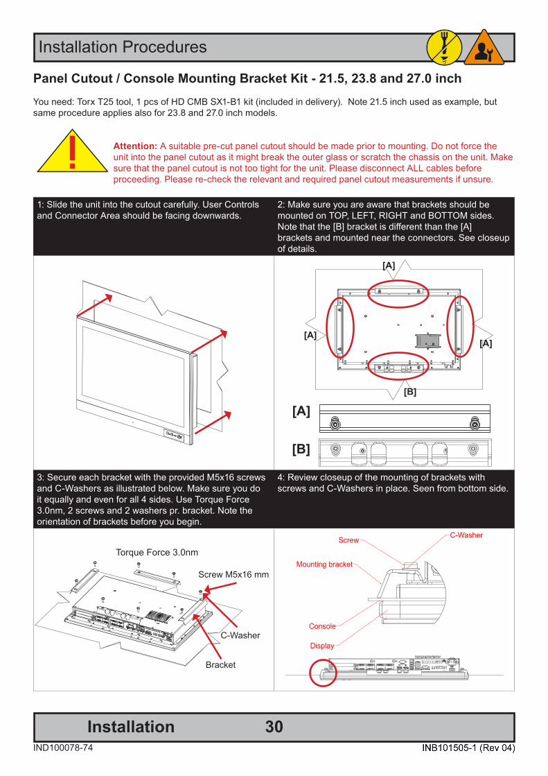
Panel Cutout / Console Mounting Bracket Kit - 21.5, 23.8 and 27.0 inchYou need: Torx T25 tool, 1 pcs of HD CMB SX1-B1 kit (included in delivery). Note 21.5 inch used as example, but same procedure applies also for 23.8 and 27.0 inch models.
Attention: A suitable pre-cut panel cutout should be made prior to mounting. Do not force the unit into the panel cutout as it might break the outer glass or scratch the chassis on the unit. Make sure that the panel cutout is not too tight for the unit. Please disconnect ALL cables beforeproceeding. Please re-check the relevant and required panel cutout measurements if unsure.
1: Slide the unit into the cutout carefully. User Controls and Connector Area should be facing downwards.
2: Make sure you are aware that brackets should be mounted on TOP, LEFT, RIGHT and BOTTOM sides. Note that the [B] bracket is different than the [A] brackets and mounted near the connectors. See closeup of details.
[A]
[B]
[A]
[A][A]
[B]
3: Secure each bracket with the provided M5x16 screws and C-Washers as illustrated below. Make sure you doit equally and even for all 4 sides. Use Torque Force 3.0nm, 2 screws and 2 washers pr. bracket. Note the orientation of brackets before you begin.
4: Review closeup of the mounting of brackets with screws and C-Washers in place. Seen from bottom side.
Torque Force 3.0nm
Screw M5x16 mm
Bracket
C-Washer
31InstallationIND100078-72
Installation Procedures
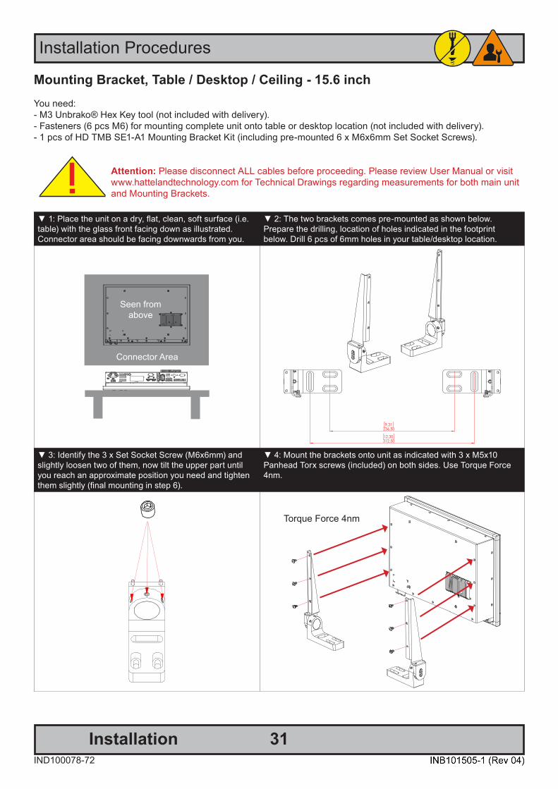
Mounting Bracket, Table / Desktop / Ceiling - 15.6 inchYou need: - M3 Unbrako® Hex Key tool (not included with delivery).- Fasteners (6 pcs M6) for mounting complete unit onto table or desktop location (not included with delivery).- 1 pcs of HD TMB SE1-A1 Mounting Bracket Kit (including pre-mounted 6 x M6x6mm Set Socket Screws).
Attention: Please disconnect ALL cables before proceeding. Please review User Manual or visit www.hattelandtechnology.com for Technical Drawings regarding measurements for both main unit and Mounting Brackets.
▼ 1: Place the unit on a dry, flat, clean, soft surface (i.e. table) with the glass front facing down as illustrated.Connector area should be facing downwards from you.
▼ 2: The two brackets comes pre-mounted as shown below.Prepare the drilling, location of holes indicated in the footprintbelow. Drill 6 pcs of 6mm holes in your table/desktop location.
Seen from above
Connector Area
▼ 3: Identify the 3 x Set Socket Screw (M6x6mm) and slightly loosen two of them, now tilt the upper part until you reach an approximate position you need and tighten them slightly (final mounting in step 6).
▼ 4: Mount the brackets onto unit as indicated with 3 x M5x10Panhead Torx screws (included) on both sides. Use Torque Force 4nm.
Torque Force 4nm
32
Installation Procedures
InstallationIND100078-72
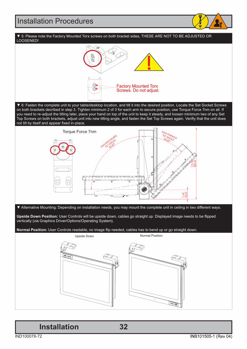
▼ 5: Please note the Factory Mounted Torx screws on both bracket sides, THESE ARE NOT TO BE ADJUSTED ORLOOSENED!
▼ 6: Fasten the complete unit to your table/desktop location, and tilt it into the desired position. Locate the Set Socket Screws on both brackets decribed in step 3. Tighten minimum 2 of 3 for each arm to secure position, use Torque Force 7nm on all. If you need to re-adjust the tilting later, place your hand on top of the unit to keep it steady, and loosen minimum two of any Set Top Screws on both brackets, adjust unit into new tilting angle, and fasten the Set Top Screws again. Verifiy that the unit does not tilt by itself and appear fixed in-place.
Torque Force 7nm
▼ Alternative Mounting: Depending on installation needs, you may mount the complete unit in ceiling in two different ways.
Upside Down Position: User Controls will be upside down, cables go straight up. Displayed image needs to be flippedvertically (via Graphics Driver/Options/Operating System).
Normal Position: User Controls readable, no image flip needed, cables has to bend up or go straight down.Upside Down Normal Position
33InstallationIND100078-73
Installation Procedures
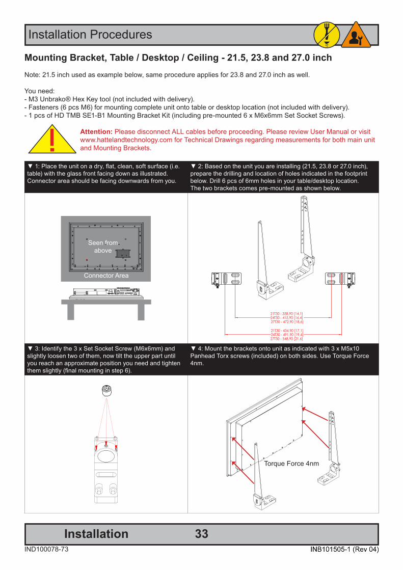
Mounting Bracket, Table / Desktop / Ceiling - 21.5, 23.8 and 27.0 inchNote: 21.5 inch used as example below, same procedure applies for 23.8 and 27.0 inch as well.
You need: - M3 Unbrako® Hex Key tool (not included with delivery).- Fasteners (6 pcs M6) for mounting complete unit onto table or desktop location (not included with delivery).- 1 pcs of HD TMB SE1-B1 Mounting Bracket Kit (including pre-mounted 6 x M6x6mm Set Socket Screws).
Attention: Please disconnect ALL cables before proceeding. Please review User Manual or visit www.hattelandtechnology.com for Technical Drawings regarding measurements for both main unit and Mounting Brackets.
▼ 1: Place the unit on a dry, flat, clean, soft surface (i.e. table) with the glass front facing down as illustrated.Connector area should be facing downwards from you.
▼ 2: Based on the unit you are installing (21.5, 23.8 or 27.0 inch),prepare the drilling and location of holes indicated in the footprintbelow. Drill 6 pcs of 6mm holes in your table/desktop location. The two brackets comes pre-mounted as shown below.
Seen from above
Connector Area
▼ 3: Identify the 3 x Set Socket Screw (M6x6mm) and slightly loosen two of them, now tilt the upper part until you reach an approximate position you need and tighten them slightly (final mounting in step 6).
▼ 4: Mount the brackets onto unit as indicated with 3 x M5x10Panhead Torx screws (included) on both sides. Use Torque Force 4nm.
Torque Force 4nm
34
Installation Procedures
InstallationIND100078-73
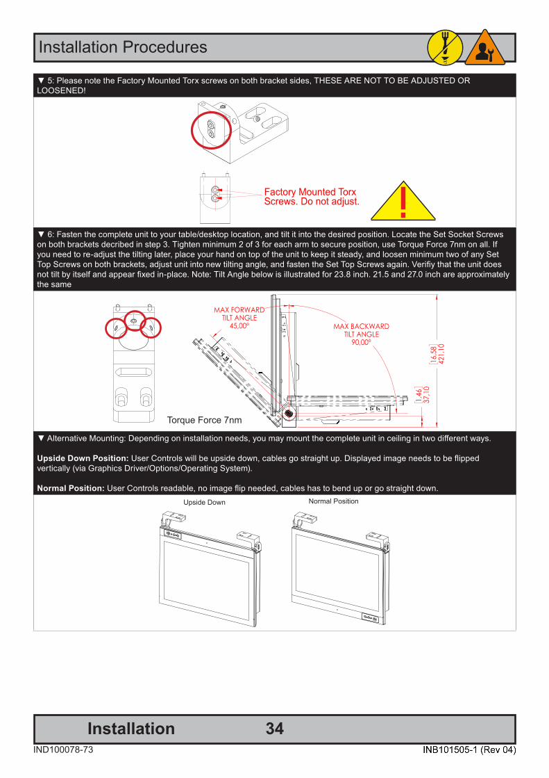
▼ 5: Please note the Factory Mounted Torx screws on both bracket sides, THESE ARE NOT TO BE ADJUSTED ORLOOSENED!
▼ 6: Fasten the complete unit to your table/desktop location, and tilt it into the desired position. Locate the Set Socket Screws on both brackets decribed in step 3. Tighten minimum 2 of 3 for each arm to secure position, use Torque Force 7nm on all. If you need to re-adjust the tilting later, place your hand on top of the unit to keep it steady, and loosen minimum two of any Set Top Screws on both brackets, adjust unit into new tilting angle, and fasten the Set Top Screws again. Verifiy that the unit does not tilt by itself and appear fixed in-place. Note: Tilt Angle below is illustrated for 23.8 inch. 21.5 and 27.0 inch are approximately the same
Torque Force 7nm
▼ Alternative Mounting: Depending on installation needs, you may mount the complete unit in ceiling in two different ways.
Upside Down Position: User Controls will be upside down, cables go straight up. Displayed image needs to be flippedvertically (via Graphics Driver/Options/Operating System).
Normal Position: User Controls readable, no image flip needed, cables has to bend up or go straight down.Upside Down Normal Position

35IND100133-74
Physical Connections
Grounding Screw (Power)
1 x RS-232/422/485 COM1
Power Input DC
4 x USB2.0
2 x RJ-45 Network (1 / 2)
2 x Removable Storage Trays
Expansion Area forOptional Modules
Grounding Screw (Modules)
1 x Audio AMP (Optional)
2 x DisplayPort (DP++) OUT
Power Input AC
Grounding Screw (Power)
1 x RS-232/422/485 COM1
Power Input DC
4 x USB2.0
2 x RJ-45 Network (1 / 2)Expansion Area forOptional Modules
Grounding Screw (Modules)
1 x Audio AMP (Optional)
2 x DisplayPort (DP++) OUT
Power Input AC
1 x RS-232/422/485 COM14 x USB2.0
2 x RJ-45 Network (1 / 2)
Grounding Screw (Power / Module)
2 x DisplayPort (DP++) OUTExpansion Area forOptional Module
Power Input AC
Power Input DC 1 x Audio AMP (Optional)
Connection area of unit 15.6 inch with 1 x Module (illustration)
Connection area of unit 21.5, 23.8 and 27.0 inch with 2 x Modules + Removable Storage Trays (illustration)
Connection area of unit 21.5, 23.8 and 27.0 inch with 3 x Modules (illustration)
1 x HDMI In (Optional Frame Grabber) 1 x VGA In (Optional Frame Grabber)
1 x RS-232/422/485 COM14 x USB2.0
2 x RJ-45 Network (1 / 2)
Grounding Screw (Power / Module)
2 x DisplayPort (DP++) OUT2 x Removable Storage TraysPower Input AC
Power Input DC 1 x Audio AMP (Optional)
Connection area of unit 15.6 inch with 1 x Removable Storage Trays (illustration)
1 x HDMI In (Optional Frame Grabber) 1 x VGA In (Optional Frame Grabber)
Physical Connections
36IND100133-74
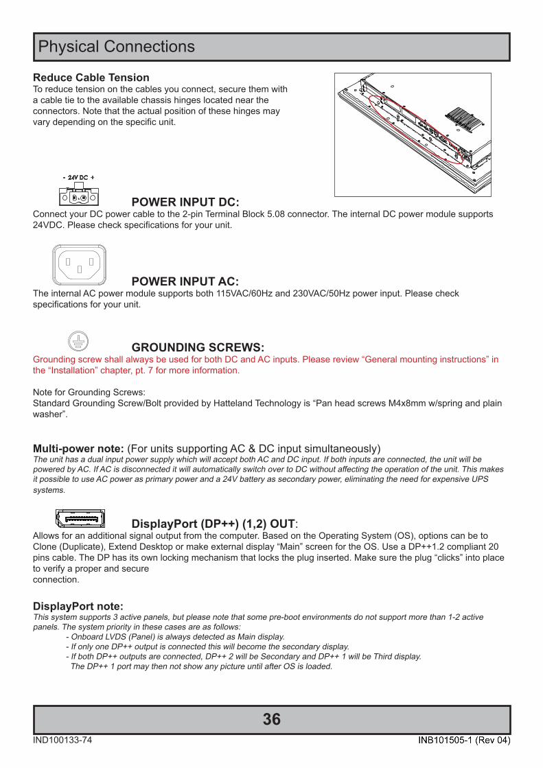
POWER INPUT DC: Connect your DC power cable to the 2-pin Terminal Block 5.08 connector. The internal DC power module supports 24VDC. Please check specifications for your unit.
POWER INPUT AC: The internal AC power module supports both 115VAC/60Hz and 230VAC/50Hz power input. Please checkspecifications for your unit.
GROUNDING SCREWS: Grounding screw shall always be used for both DC and AC inputs. Please review “General mounting instructions” in the “Installation” chapter, pt. 7 for more information.
Note for Grounding Screws:Standard Grounding Screw/Bolt provided by Hatteland Technology is “Pan head screws M4x8mm w/spring and plainwasher”.
Multi-power note: (For units supporting AC & DC input simultaneously) The unit has a dual input power supply which will accept both AC and DC input. If both inputs are connected, the unit will bepowered by AC. If AC is disconnected it will automatically switch over to DC without affecting the operation of the unit. This makes it possible to use AC power as primary power and a 24V battery as secondary power, eliminating the need for expensive UPS systems.
DisplayPort (DP++) (1,2) OUT:Allows for an additional signal output from the computer. Based on the Operating System (OS), options can be to Clone (Duplicate), Extend Desktop or make external display “Main” screen for the OS. Use a DP++1.2 compliant 20 pins cable. The DP has its own locking mechanism that locks the plug inserted. Make sure the plug “clicks” into place to verify a proper and secureconnection.
DisplayPort note: This system supports 3 active panels, but please note that some pre-boot environments do not support more than 1-2 active panels. The system priority in these cases are as follows: - Onboard LVDS (Panel) is always detected as Main display. - If only one DP++ output is connected this will become the secondary display. - If both DP++ outputs are connected, DP++ 2 will be Secondary and DP++ 1 will be Third display. The DP++ 1 port may then not show any picture until after OS is loaded.
Reduce Cable TensionTo reduce tension on the cables you connect, secure them with a cable tie to the available chassis hinges located near theconnectors. Note that the actual position of these hinges may vary depending on the specific unit.
Physical Connections
37IND100133-74
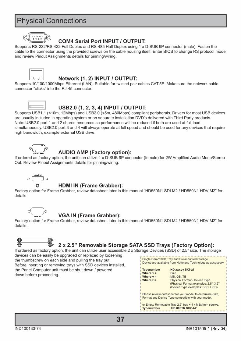
COM4 Serial Port INPUT / OUTPUT:Supports RS-232/RS-422 Full Duplex and RS-485 Half Duplex using 1 x D-SUB 9P connector (male). Fasten the cable to the connector using the provided screws on the cable housing itself. Enter BIOS to change RS protocol mode and review Pinout Assignments details for pinning/wiring.
Network (1, 2) INPUT / OUTPUT:Supports 10/100/1000Mbps Ethernet (LAN). Suitable for twisted pair cables CAT.5E. Make sure the network cable connector ”clicks” into the RJ-45 connector.
USB2.0 (1, 2, 3, 4) INPUT / OUTPUT:Supports USB1.1 (<10m, 12Mbps) and USB2.0 (<5m, 480Mbps) compliant peripherals. Drivers for most USB devices are usually included in operating system or on separate installation DVD’s delivered with Third Party products. Note: USB2.0 port 1 and 2 shares resources so performance will be reduced if both are used at full loadsimultaneously. USB2.0 port 3 and 4 will always operate at full speed and should be used for any devices that require high bandwidth, example external USB drive.
AUDIO AMP (Factory option):If ordered as factory option, the unit can utilize 1 x D-SUB 9P connector (female) for 2W Amplified Audio Mono/Stereo Out. Review Pinout Assignments details for pinning/wiring.
HDMI IN (Frame Grabber):Factory option for Frame Grabber, review datasheet later in this manual “HD550N1 SDI M2 / HD550N1 HDV M2” for details .
VGA IN (Frame Grabber):Factory option for Frame Grabber, review datasheet later in this manual “HD550N1 SDI M2 / HD550N1 HDV M2” for details .
2 x 2.5” Removable Storage SATA SSD Trays (Factory Option):If ordered as factory option, the unit can utilize user accessible 2 x Storage Devices (SSD) of 2.5” size. The storagedevices can be easily be upgraded or replaced by looseningthe thumbscrew on each side and pulling the tray out. Before inserting or removing trays with SSD devices installed,the Panel Computer unit must be shut down / powereddown before proceeding.
Single Removable Tray and Pre-mounted StorageDevice are available from Hatteland Technology as accessory.
Typenumber : HD xxxyy SX1-z1Where x = : SizeWhere y = : MB, GB, TBWhere z = : Physical Format / Device Type (Physical Format examples: 2.5”, 3.5”) (Device Type examples: SSD, HDD)
Please review datasheet for your model to determine Size, Format and Device Type compatible with your model.
or Empty Removable Tray 2.5” tray + 4 x M3x4mm screws.Typenumber : HD 000TR SX2-A2
Physical Connections
38IND100133-74
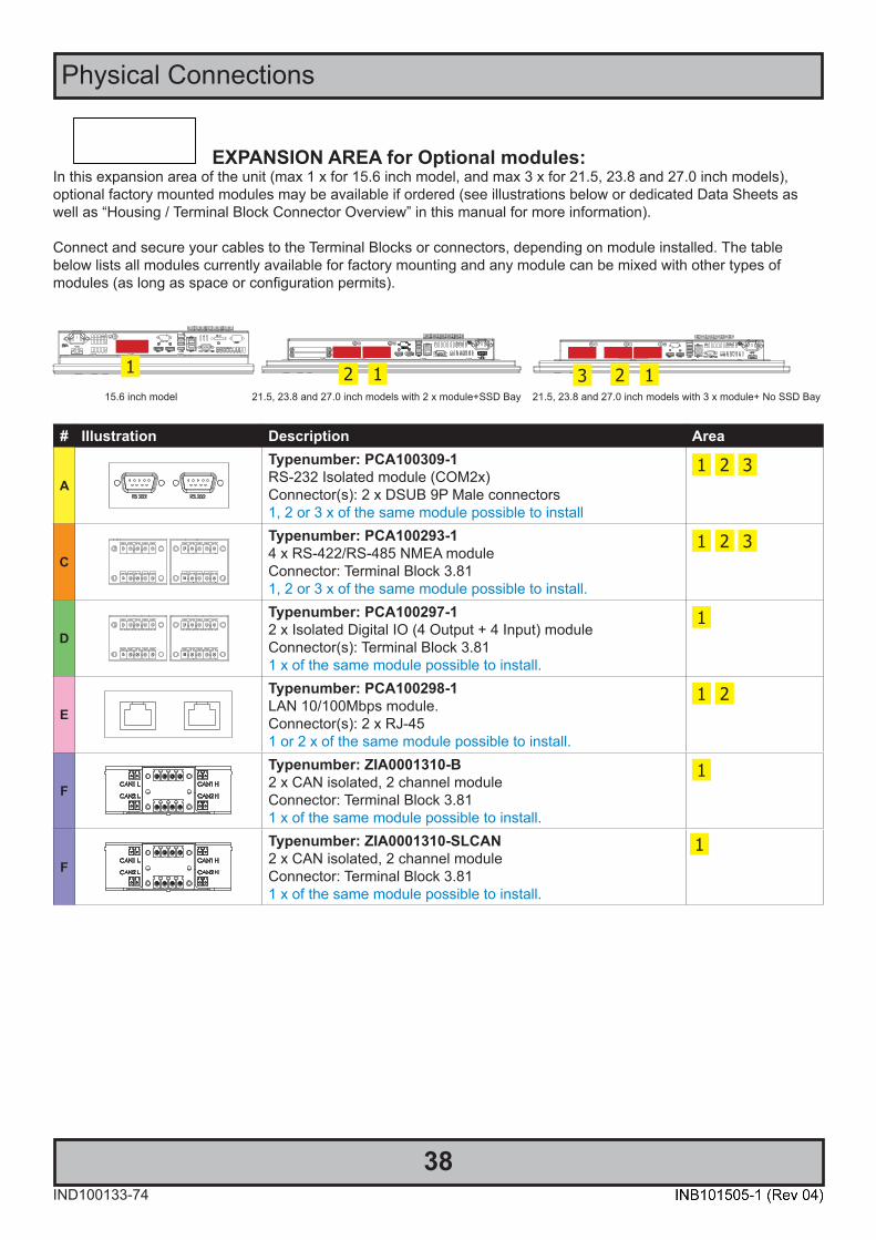
EXPANSION AREA for Optional modules:In this expansion area of the unit (max 1 x for 15.6 inch model, and max 3 x for 21.5, 23.8 and 27.0 inch models), optional factory mounted modules may be available if ordered (see illustrations below or dedicated Data Sheets as well as “Housing / Terminal Block Connector Overview” in this manual for more information).
Connect and secure your cables to the Terminal Blocks or connectors, depending on module installed. The table below lists all modules currently available for factory mounting and any module can be mixed with other types ofmodules (as long as space or configuration permits).
1 12 123 15.6 inch model 21.5, 23.8 and 27.0 inch models with 2 x module+SSD Bay 21.5, 23.8 and 27.0 inch models with 3 x module+ No SSD Bay
# Illustration Description Area
A
Typenumber: PCA100309-1RS-232 Isolated module (COM2x)Connector(s): 2 x DSUB 9P Male connectors1, 2 or 3 x of the same module possible to install
1 2 3
C
Typenumber: PCA100293-14 x RS-422/RS-485 NMEA moduleConnector: Terminal Block 3.811, 2 or 3 x of the same module possible to install.
1 2 3
D
Typenumber: PCA100297-12 x Isolated Digital IO (4 Output + 4 Input) moduleConnector(s): Terminal Block 3.811 x of the same module possible to install.
1
E
Typenumber: PCA100298-1LAN 10/100Mbps module.Connector(s): 2 x RJ-451 or 2 x of the same module possible to install.
1 2
F
Typenumber: ZIA0001310-B2 x CAN isolated, 2 channel moduleConnector: Terminal Block 3.811 x of the same module possible to install.
1
F
Typenumber: ZIA0001310-SLCAN2 x CAN isolated, 2 channel moduleConnector: Terminal Block 3.811 x of the same module possible to install.
1
Physical Connections
39IND100133-74
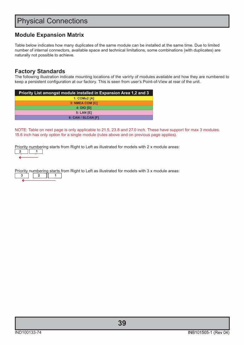
Module Expansion MatrixTable below indicates how many duplicates of the same module can be installed at the same time. Due to limited number of internal connectors, available space and technical limitations, some combinations (with duplicates) are naturally not possible to achieve.
Factory StandardsThe following illustration indicate mounting locations of the varirty of modules available and how they are numbered to keep a persistent configuration at our factory. This is seen from user’s Point-of-View at rear of the unit.
Priority List amongst module installed in Expansion Area 1,2 and 31: COMx2 [A]
3: NMEA COM [C]4: DIO [D]5: LAN [E]
6: CAN / SLCAN [F]
NOTE: Table on next page is only applicable to 21.5, 23.8 and 27.0 inch. These have support for max 3 modules.15.6 inch has only option for a single module (rules above and on previous page applies).
Priority numbering starts from Right to Left as illustrated for models with 2 x module areas:2 1
Priority numbering starts from Right to Left as illustrated for models with 3 x module areas:2 13
Physical Connections
40IND100133-74
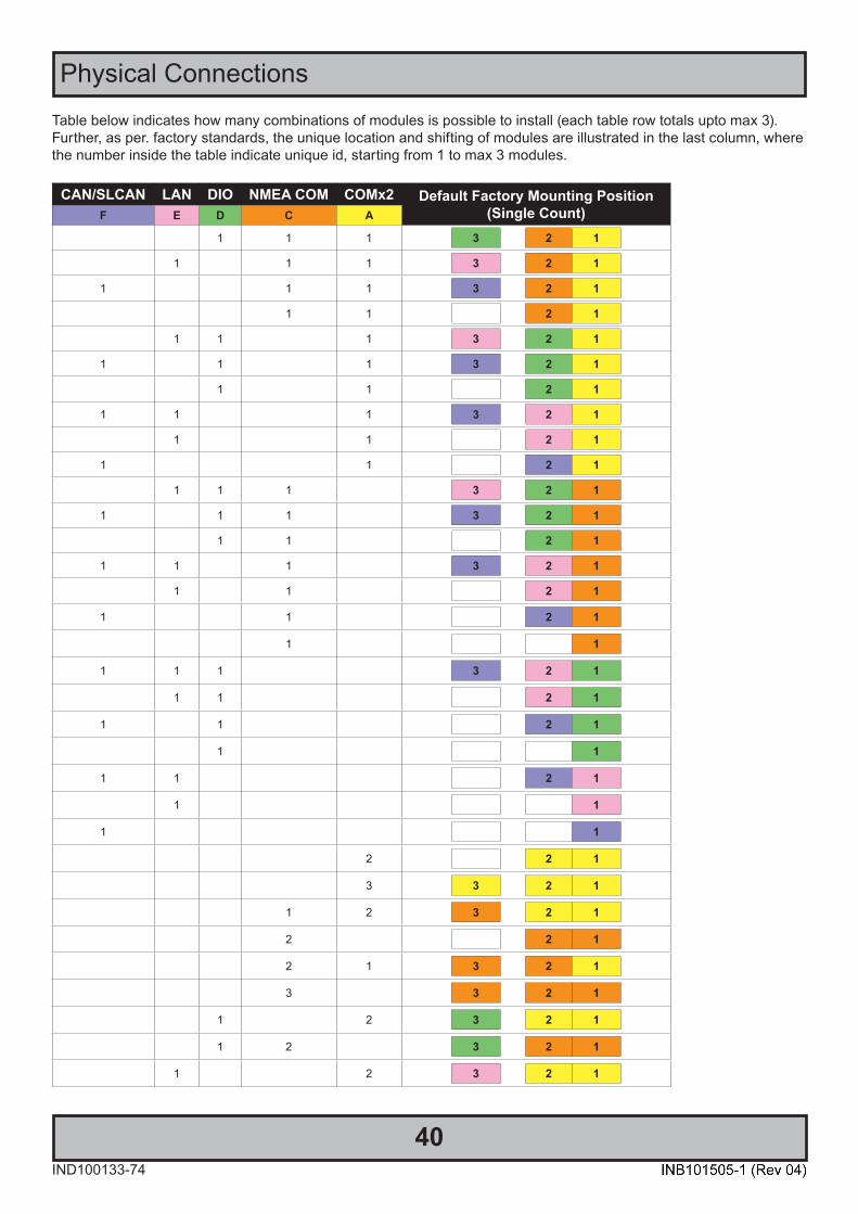
Table below indicates how many combinations of modules is possible to install (each table row totals upto max 3).Further, as per. factory standards, the unique location and shifting of modules are illustrated in the last column, where the number inside the table indicate unique id, starting from 1 to max 3 modules.
CAN/SLCAN LAN DIO NMEA COM COMx2 Default Factory Mounting Position(Single Count)F E D C A
1 1 1 3 2 1
1 1 1 3 2 1
1 1 1 3 2 1
1 1 2 1
1 1 1 3 2 1
1 1 1 3 2 1
1 1 2 1
1 1 1 3 2 1
1 1 2 1
1 1 2 1
1 1 1 3 2 1
1 1 1 3 2 1
1 1 2 1
1 1 1 3 2 1
1 1 2 1
1 1 2 1
1 1
1 1 1 3 2 1
1 1 2 1
1 1 2 1
1 1
1 1 2 1
1 1
1 1
2 2 1
3 3 2 1
1 2 3 2 1
2 2 1
2 1 3 2 1
3 3 2 1
1 2 3 2 1
1 2 3 2 1
1 2 3 2 1

Physical Connections
41IND100133-74
CAN/SLCAN LAN DIO NMEA COM COMx2 Default Factory Mounting Position(Single Count)F E D C A
1 2 3 2 1
2 2 1
2 1 3 2 1
2 1 3 2 1
2 1 3 2 1
1 2 3 2 1
1 2 3 2 1
1 2 3 2 1
COM Ports Numbering Default numbering on a factory standard model (example: Microsoft® Windows® 10) are as follow:COM 1,2,3 = 3 x System Reserved (COM1 = internal SCOM, see below for details)COM 4 = 1 x Physical Port, COM RS-232/422/485COM 5 = 1 x Physical Port, CAN/SLCAN Module - (if factory option, 1st “ZIA0001310-B / ZIA0001310-SLCAN”)COM 6 = 1 x Physical Port, CAN/SLCAN Module - (if factory option, 2nd “ZIA0001310-B / ZIA0001310-SLCAN”)COM 7-10 = 4 x Physical Port, RS-422/RS-485 NMEA Module - (if factory option, 1st “PCA200828-1”)COM 11-14 = 4 x Physical Port, RS-422/RS-485 NMEA Module - (if factory option, 2nd “PCA200828-1”)COM 15-16 = 2 x Physical Port, RS-232 Isolated Module - (if factory option, 1st “PCA100309-1”)COM 17-18 = 2 x Physical Port, RS-232 Isolated Module - (if factory option, 2nd “PCA100309-1”)
COM ports are not reserved nor locked by BIOS. COM Port numbering may differ depending on OS used andcustomized solutions. Use the Operating System functions to determine actual port numbering, if problems arise.
Note: Internal (COM1 port) support for remote controlling MMC units:A detailed description of the SCOM (Serial/Ethernet Communication) can be found here:https://www.hattelandtechnology.com/hubfs/pdfget/inb100018-7.htm - Review also the “Pinout Assignments” chapter in this manual for additional help during preperation and/or installation of external equipment intended to communicate with.

42
This page left intentionally blank

43
Operation
44IND100064-68
Operation
User Controls
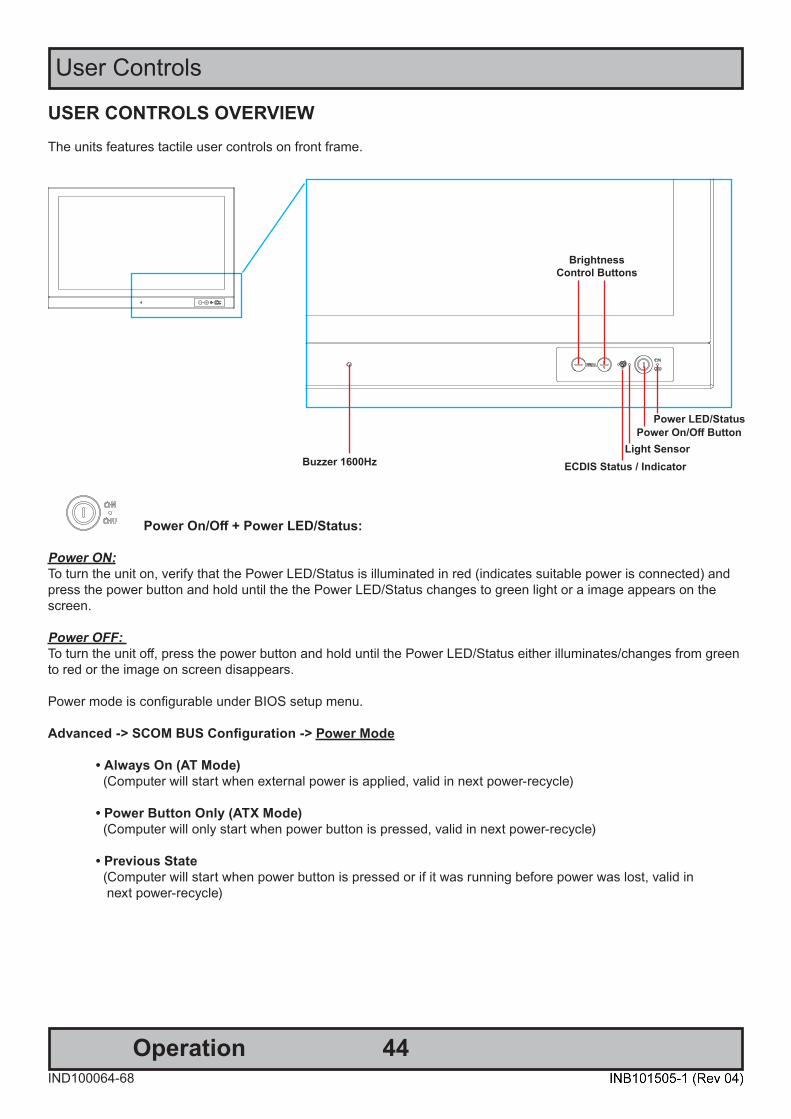
USER CONTROLS OVERVIEWThe units features tactile user controls on front frame.
Power On/Off + Power LED/Status:
Power ON: To turn the unit on, verify that the Power LED/Status is illuminated in red (indicates suitable power is connected) and press the power button and hold until the the Power LED/Status changes to green light or a image appears on the screen.
Power OFF: To turn the unit off, press the power button and hold until the Power LED/Status either illuminates/changes from green to red or the image on screen disappears.
Power mode is configurable under BIOS setup menu.
Advanced -> SCOM BUS Configuration -> Power Mode
• Always On (AT Mode) (Computer will start when external power is applied, valid in next power-recycle)
• Power Button Only (ATX Mode) (Computer will only start when power button is pressed, valid in next power-recycle)
• Previous State (Computer will start when power button is pressed or if it was running before power was lost, valid in next power-recycle)
BrightnessControl Buttons
ECDIS Status / Indicator
Power On/Off ButtonLight Sensor
Buzzer 1600Hz
Power LED/Status

45Operation
User Controls
IND100064-68
Brightness Adjust:Brilliance / Brightness adjustment of the displayed image is adjusted by pressing the (-) or (+) buttons.
ECDIS Status / Indicator: (optional factory standard)For units that have been factory ECDIS calibrated the small circle located next to the Globe symbol will illuminate in green constantly as long as the unit is powered. The “+” and “-” symbols will illuminate in orange when the Brightness/Brillance is adjusted either above or below ECDIS factory calibration point.
To be able to stay within ECDIS calibrated range, please assure that both the “+” and “-” are not illuminated and that the ECDIS light remains illuminated in green during operation.
Buzzer:To take advantage of the buzzer, please review the SCOM (Serial/Ethernet Communication) manual located here:https://www.hattelandtechnology.com/hubfs/pdfget/inb100018-7.htm (reference: “BZZ” - Buzzer Control command, through the Internal COM1 port).
Touching this area will naturally mute buzzer sound or in some cases make it lower or change audible frequency. In no circumstances should this area be blocked by either stickers or objects!
Light Sensor:Located next to the ECDIS (Globe) symbol. The Light Sensor is used to sense level of ambient light in the surrounding environment. The sensor data can be read by suitable software through the Hatteland Technology SCOM functionality of the unit and thus can be used to control brightness remotely. Touching or covering this area will naturally make the sensor data inaccurate and should be avoided!
Hatteland Technology’s Serial Remote Control Interface (SCOM) protocol document can be downloaded from:https://www.hattelandtechnology.com/hubfs/pdfget/inb100018-7.htm

46
This page left intentionally blank

47
Specifications

48IND100129-233
All specifications are subject to change without prior notice!
Specifications - HD 16T30 MMC-xxx-xxxxxxSPECIFICATIONS Note: All specifi cations are subject to change without prior notice!
Please visit www.hattelandtechnology.com for the latest electronic version.
2/2
• W:397.60 [15.65"] x H:279.50 [11.00"] x D:94.50 [3.72"] mm [inch] • VESA 200x200 supported. Additional spacers needed to get distance from CPU Cooler• Weight: Approx. 4.3kg / 9.48lbs
• 15.6 inch TFT Liquid Crystal Display module, VA (Vertical Alignment)• a-si TFT Active Matrix • Widescreen, Aspect Ratio 16:9• LED Backlight Technology
On front bezel IP66:• Power On/Off, Brightness Control (-/+), Power LED, ECDIS LED• Buzzer, Light Sensor
A P P R O V A L S & C E R T I F I C A T E S
Physical Dimensions:TFT Technology:
This product have been tested / type approved by the following classification societies:IEC 60945 4th (EN 60945:2002) IACS E10 EU RO MR - Mutual Recognition ClassNK - Nippon Kaiji KyokaiCCS - China Classification Society
User Controls:
• Native Resolution : 1920 x 1080 (FHD)• Pixel Pitch (RGB) : 0.17925 (H) x 0.17925 (V) mm• Response Time : 35ms (tr+tf) (typ)• Contrast Ratio : 1500:1 (typ) • Light Intensity : 400 cd/m2 (typ)• Viewable Angle : 85 deg. (up/down/left/right) (typical)• Active Display Area : 344.16 (H) x 193.59 (V) mm• Max Colors : 16.77M colors (RGB 8-bit)
TFT Characteristics:
Power Supply Options:• Multi-Power option : 100-240V AC - 50/60Hz + 24VDC (MMC-Mxx)• Single AC Power Option : 100-240V AC - 50/60Hz (MMC-Axx)
Note: You may connect either AC power or DC power or both. In case both sources are connected, power will be sourced from the AC input. If AC input is lost, there will be a uninterrupted switch-over to DC input.
Power Consumption: *(see note)• Operating AC/DC : 44W (typ) - 75W (max)• Operating AC : 44W (typ) - 125W (max)
• Supported OS : See table below• CPU/Processor : 1 x Intel Atom® x7-E3950 Processor, 2M Cache,
1.60GHz / 2.00GHz• Installed Storage : 32GB eMMC (Default). See table below• Installed Memory : 2GB DDR3L single channel. See table below• System Chipset : Intel® SOC• Graphics Chipset : Intel® HD Graphics 505 (CPU dependent)
Supports OpenGL 4.6 (Windows/Linux) and OpenGL ES 3.2 (Linux)
• Ethernet LAN #1 : Realtek Gigabit LAN 10/100/1000Mbps• Ethernet LAN #2 : Intel Gigabit LAN 10/100/1000Mbps• BIOS : AMI BIOS, supports ACPI
Note: "Legacy Mode" option is not fully supported for System Chipset and Microsoft® Windows® 10.
• Buzzer : Yes (according to EN60945)• Speaker : None• WatchDog Timer : Yes (256 segments, 0, 1, 2...255 sec/min)• Other features : RTC (0.5s/day), Battery Alarm, WakeOnLan,
Fast Boot, AT mode, USB Boot, TPM2.0• DP++ Out Max Res. : 640 x 480 to 4096 x 2304 @ 60Hz
Power Specifications:
Computer Specifications:
• Operating Temperature : -15°C to +55°C• Storage Temperature : -20°C to +60°C• Humidity : Humidity up to 95% (Operating / Storage)• IP-Rating Protection : IP66 front - IP20 rear (EN60529). IP22=option• Compass Safe Distance : Standard: 60cm - Steering: 35cmLifetime Considerations:Even though the test conditions for bridge units provide for a maximumoperating temperature of 55°C, continuous operation of all electroniccomponents should, if possible, take place at ambient temperatures of only25°C. This is a necessary prerequisite for long life and low service costs.
Environmental Considerations:
Connector Rear• DisplayPort (DP++) Out : 2 x 20p DisplayPort (female)• USB2.0 : 4 x USB Type A• Ethernet GBLan : 2 x RJ-45• COM RS-232 & 422/485 : 1 x DB9M non-isolated (Change RS mode in BIOS)• AC Power IN : 1 x Std IEC inlet• If DC Power IN : 1 x 2-pin Terminal Block 5.08
Input/Output Connectors:
• Projected Capacitive Touch Screen (Multitouch,USB,Pen/Glove support)• Optical Bonding Technology• Variations of Storage, RAM Memory and Operating Systems.• 1 x HT 00235 OPT-A1: 2W Amplified Audio out via DB9F
- Model with 1 x Diskbay with support for 2 x 2.5", no modules- Model with 1 x Module, no Diskbay
Modules available (depending on base model above):Review full configuration matrix in User Manual INB101505-11 x PCA200828-1: 4xCOM RS-422/485 isolated NMEA 4 channelor 1 x PCA100309-1: Dual Isolated RS-232, connector 2xDB9or 1 x ZIA0001310-B: CAN isolated 2 channel or 2 x 4 channelor 1 x ZIA0001310-SLCAN (1 x CAN isolated, 2 channel, socketCAN) moduleor 1 x PCA100297-1: Isolated Digital IO module,4 x OUT/4 x INor 1 x PCA100298-1: LAN 10/100Mbps, 2 ports RJ45
Frame Grabber options (1 x supported via M.2 (PCIe x1) slot):• HD550N1 SDI M2: 1 x SDI IN, 1920x1080@60/50fps• HD550N1 HDV M2: 1 x HDMI IN+1 x VGA IN, 1920x1200p@60/50fps
Factory Options:
• HD CMB SE1-A1 : 1 x Console Mount kit. EN60945 Tested*• HD TMB SE1-A1 : 1 x Table Mount Bracket. EN60945 Tested• JH C01MF A-A : 1 x USB Cable 1m, TypeA-Chassis mount receptacle• HT 00262 OPT-A1: 4 x RS-422/RS-485 isolated, USB ext. module• HT 00263 OPT-A1: 4 x RS-232 COM non-isolated, USB ext. module• HT 00264 OPT-A1: 1 x CAN isolated, 2 channel, USB ext. module• HT 00273 OPT-A1: 4 x Digital IN/OUT isolated, USB ext. module• HT 00274 OPT-A1: 2 x LAN 10/100Mbps, RJ45, USB ext. module• HT 00300 MSOS : OS options:https://www.hattelandtechnology.com/options-for-downgrade-upgrade-change-or-add-of-microsoft-windows
*Included in delivery
Accessories:Available Computer Configurations: Type Description Size/SpecificationMemory/RAM DDR3L, 1600MHz,
SO-DIMM- 2GB Single Channel- 4GB (2x2GB) - Dual Channel- 8GB (2x4GB) - Dual Channel
Additional InternalStorage
m.2 - 240GB->
Software Support Application Programming Interface (API) - as defined in associated documents
- SCOM
OS Options Windows® 10 IoT Enterprise 2019 LTSC (64bit)- Product Distribution End Date January 2029or Linux: Kernel 4.10 or later
*Power Consumption: Numbers are specified as the unit is delivered from factory.All additional installed equipment like USB, PCIe and similar loads have to be addedto power consumption. Note that total extra load have to be multiplied by 1.5 tocompensate for efficiency in internal power converters. Typical power consumptionvaries a lot with computer load. We measure with 25% of max computer load.
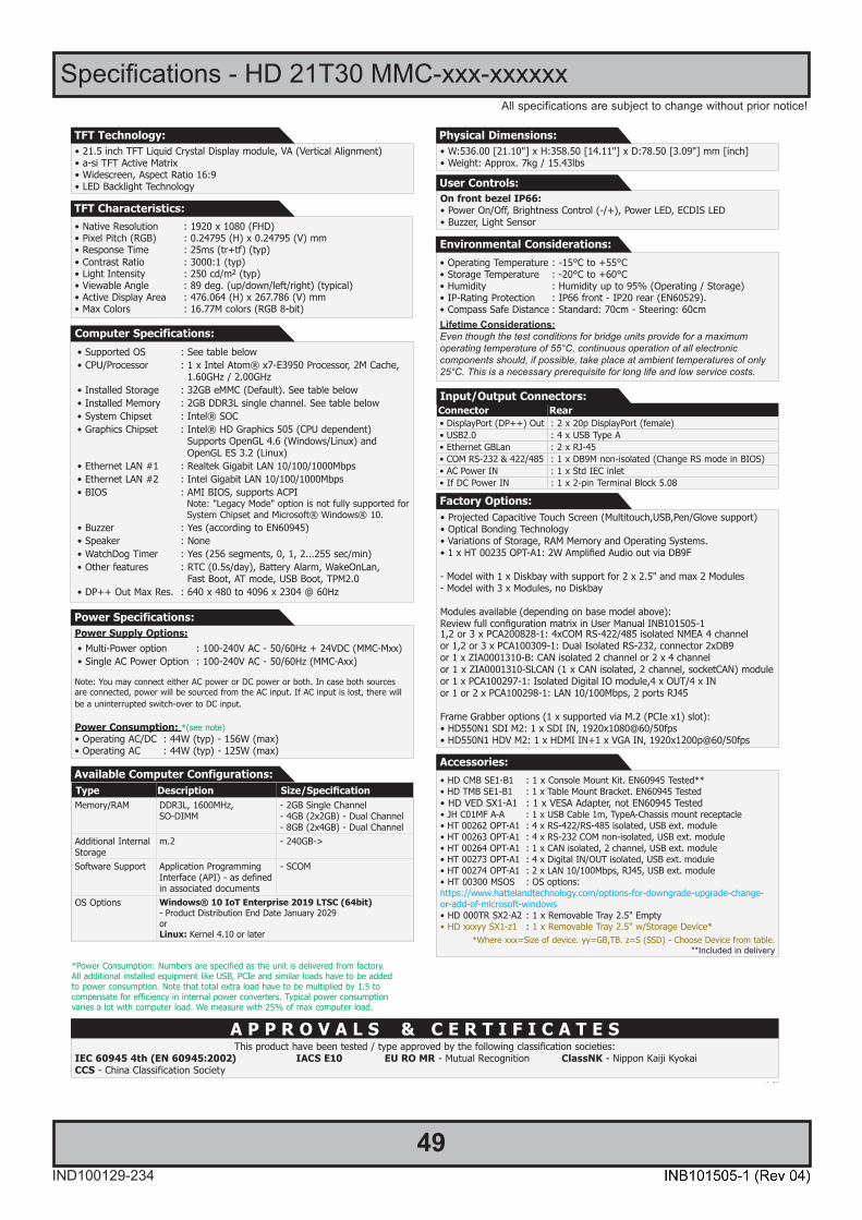
49IND100129-234
All specifications are subject to change without prior notice!
Specifications - HD 21T30 MMC-xxx-xxxxxxSPECIFICATIONS Note: All specifi cations are subject to change without prior notice!
Please visit www.hattelandtechnology.com for the latest electronic version.
2/2
• W:536.00 [21.10"] x H:358.50 [14.11"] x D:78.50 [3.09"] mm [inch] • Weight: Approx. 7kg / 15.43lbs
• 21.5 inch TFT Liquid Crystal Display module, VA (Vertical Alignment)• a-si TFT Active Matrix • Widescreen, Aspect Ratio 16:9• LED Backlight Technology
On front bezel IP66:• Power On/Off, Brightness Control (-/+), Power LED, ECDIS LED• Buzzer, Light Sensor
A P P R O V A L S & C E R T I F I C A T E S
Physical Dimensions:TFT Technology:
This product have been tested / type approved by the following classification societies:IEC 60945 4th (EN 60945:2002) IACS E10 EU RO MR - Mutual Recognition ClassNK - Nippon Kaiji KyokaiCCS - China Classification Society
User Controls:
• Native Resolution : 1920 x 1080 (FHD)• Pixel Pitch (RGB) : 0.24795 (H) x 0.24795 (V) mm• Response Time : 25ms (tr+tf) (typ)• Contrast Ratio : 3000:1 (typ) • Light Intensity : 250 cd/m2 (typ)• Viewable Angle : 89 deg. (up/down/left/right) (typical)• Active Display Area : 476.064 (H) x 267.786 (V) mm• Max Colors : 16.77M colors (RGB 8-bit)
TFT Characteristics:
• Supported OS : See table below• CPU/Processor : 1 x Intel Atom® x7-E3950 Processor, 2M Cache,
1.60GHz / 2.00GHz• Installed Storage : 32GB eMMC (Default). See table below• Installed Memory : 2GB DDR3L single channel. See table below• System Chipset : Intel® SOC• Graphics Chipset : Intel® HD Graphics 505 (CPU dependent)
Supports OpenGL 4.6 (Windows/Linux) and OpenGL ES 3.2 (Linux)
• Ethernet LAN #1 : Realtek Gigabit LAN 10/100/1000Mbps• Ethernet LAN #2 : Intel Gigabit LAN 10/100/1000Mbps• BIOS : AMI BIOS, supports ACPI
Note: "Legacy Mode" option is not fully supported for System Chipset and Microsoft® Windows® 10.
• Buzzer : Yes (according to EN60945)• Speaker : None• WatchDog Timer : Yes (256 segments, 0, 1, 2...255 sec/min)• Other features : RTC (0.5s/day), Battery Alarm, WakeOnLan,
Fast Boot, AT mode, USB Boot, TPM2.0• DP++ Out Max Res. : 640 x 480 to 4096 x 2304 @ 60Hz
Computer Specifications:
• Operating Temperature : -15°C to +55°C• Storage Temperature : -20°C to +60°C• Humidity : Humidity up to 95% (Operating / Storage)• IP-Rating Protection : IP66 front - IP20 rear (EN60529). • Compass Safe Distance : Standard: 70cm - Steering: 60cmLifetime Considerations:Even though the test conditions for bridge units provide for a maximumoperating temperature of 55°C, continuous operation of all electroniccomponents should, if possible, take place at ambient temperatures of only25°C. This is a necessary prerequisite for long life and low service costs.
Environmental Considerations:
• Projected Capacitive Touch Screen (Multitouch,USB,Pen/Glove support)• Optical Bonding Technology• Variations of Storage, RAM Memory and Operating Systems.• 1 x HT 00235 OPT-A1: 2W Amplified Audio out via DB9F
- Model with 1 x Diskbay with support for 2 x 2.5" and max 2 Modules- Model with 3 x Modules, no Diskbay
Modules available (depending on base model above):Review full configuration matrix in User Manual INB101505-11,2 or 3 x PCA200828-1: 4xCOM RS-422/485 isolated NMEA 4 channelor 1,2 or 3 x PCA100309-1: Dual Isolated RS-232, connector 2xDB9or 1 x ZIA0001310-B: CAN isolated 2 channel or 2 x 4 channelor 1 x ZIA0001310-SLCAN (1 x CAN isolated, 2 channel, socketCAN) moduleor 1 x PCA100297-1: Isolated Digital IO module,4 x OUT/4 x INor 1 or 2 x PCA100298-1: LAN 10/100Mbps, 2 ports RJ45
Frame Grabber options (1 x supported via M.2 (PCIe x1) slot):• HD550N1 SDI M2: 1 x SDI IN, 1920x1080@60/50fps• HD550N1 HDV M2: 1 x HDMI IN+1 x VGA IN, 1920x1200p@60/50fps
Factory Options:
Power Supply Options:• Multi-Power option : 100-240V AC - 50/60Hz + 24VDC (MMC-Mxx)• Single AC Power Option : 100-240V AC - 50/60Hz (MMC-Axx)
Note: You may connect either AC power or DC power or both. In case both sources are connected, power will be sourced from the AC input. If AC input is lost, there will be a uninterrupted switch-over to DC input.
Power Consumption: *(see note)• Operating AC/DC : 44W (typ) - 156W (max)• Operating AC : 44W (typ) - 125W (max)
Power Specifications:
• HD CMB SE1-B1 : 1 x Console Mount Kit. EN60945 Tested**• HD TMB SE1-B1 : 1 x Table Mount Bracket. EN60945 Tested• HD VED SX1-A1 : 1 x VESA Adapter, not EN60945 Tested• JH C01MF A-A : 1 x USB Cable 1m, TypeA-Chassis mount receptacle• HT 00262 OPT-A1 : 4 x RS-422/RS-485 isolated, USB ext. module• HT 00263 OPT-A1 : 4 x RS-232 COM non-isolated, USB ext. module• HT 00264 OPT-A1 : 1 x CAN isolated, 2 channel, USB ext. module• HT 00273 OPT-A1 : 4 x Digital IN/OUT isolated, USB ext. module• HT 00274 OPT-A1 : 2 x LAN 10/100Mbps, RJ45, USB ext. module• HT 00300 MSOS : OS options:https://www.hattelandtechnology.com/options-for-downgrade-upgrade-change-or-add-of-microsoft-windows• HD 000TR SX2-A2 : 1 x Removable Tray 2.5" Empty• HD xxxyy SX1-z1 : 1 x Removable Tray 2.5" w/Storage Device*
*Where xxx=Size of device. yy=GB,TB. z=S (SSD) - Choose Device from table.**Included in delivery
Accessories:
Connector Rear• DisplayPort (DP++) Out : 2 x 20p DisplayPort (female)• USB2.0 : 4 x USB Type A• Ethernet GBLan : 2 x RJ-45• COM RS-232 & 422/485 : 1 x DB9M non-isolated (Change RS mode in BIOS)• AC Power IN : 1 x Std IEC inlet• If DC Power IN : 1 x 2-pin Terminal Block 5.08
Input/Output Connectors:
Available Computer Configurations: Type Description Size/SpecificationMemory/RAM DDR3L, 1600MHz,
SO-DIMM- 2GB Single Channel- 4GB (2x2GB) - Dual Channel- 8GB (2x4GB) - Dual Channel
Additional InternalStorage
m.2 - 240GB->
Software Support Application Programming Interface (API) - as defined in associated documents
- SCOM
OS Options Windows® 10 IoT Enterprise 2019 LTSC (64bit)- Product Distribution End Date January 2029or Linux: Kernel 4.10 or later
*Power Consumption: Numbers are specified as the unit is delivered from factory.All additional installed equipment like USB, PCIe and similar loads have to be addedto power consumption. Note that total extra load have to be multiplied by 1.5 tocompensate for efficiency in internal power converters. Typical power consumptionvaries a lot with computer load. We measure with 25% of max computer load.

50IND100129-235
All specifications are subject to change without prior notice!
Specifications - HD 24T30 MMC-xxx-xxxxxxSPECIFICATIONS Note: All specifi cations are subject to change without prior notice!
Please visit www.hattelandtechnology.com for the latest electronic version.
2/2
• W:593.00 [23.35"] x H:384.00 [15.12"] x D:78.50 [3.09"] mm [inch] • Weight: Approx. 8.5kg / 18.74lbs
On front bezel IP66:• Power On/Off, Brightness Control (-/+), Power LED, ECDIS LED• Buzzer, Light Sensor
A P P R O V A L S & C E R T I F I C A T E S
Physical Dimensions:
This product have been tested / type approved by the following classification societies:IEC 60945 4th (EN 60945:2002) IACS E10 EU RO MR - Mutual Recognition ClassNK - Nippon Kaiji KyokaiCCS - China Classification Society
User Controls:
• Supported OS : See table below• CPU/Processor : 1 x Intel Atom® x7-E3950 Processor, 2M Cache,
1.60GHz / 2.00GHz• Installed Storage : 32GB eMMC (Default). See table below• Installed Memory : 2GB DDR3L single channel. See table below• System Chipset : Intel® SOC• Graphics Chipset : Intel® HD Graphics 505 (CPU dependent)
Supports OpenGL 4.6 (Windows/Linux) and OpenGL ES 3.2 (Linux)
• Ethernet LAN #1 : Realtek Gigabit LAN 10/100/1000Mbps• Ethernet LAN #2 : Intel Gigabit LAN 10/100/1000Mbps• BIOS : AMI BIOS, supports ACPI
Note: "Legacy Mode" option is not fully supported for System Chipset and Microsoft® Windows® 10.
• Buzzer : Yes (according to EN60945)• Speaker : None• WatchDog Timer : Yes (256 segments, 0, 1, 2...255 sec/min)• Other features : RTC (0.5s/day), Battery Alarm, WakeOnLan,
Fast Boot, AT mode, USB Boot, TPM2.0• DP++ Out Max Res. : 640 x 480 to 4096 x 2304 @ 60Hz
Computer Specifications:
• Operating Temperature : -15°C to +55°C• Storage Temperature : -20°C to +60°C• Humidity : Humidity up to 95% (Operating / Storage)• IP-Rating Protection : IP66 front - IP20 rear (EN60529). • Compass Safe Distance : Standard: 80m - Steering: 60cmLifetime Considerations:Even though the test conditions for bridge units provide for a maximumoperating temperature of 55°C, continuous operation of all electroniccomponents should, if possible, take place at ambient temperatures of only25°C. This is a necessary prerequisite for long life and low service costs.
Environmental Considerations:
Power Supply Options:• Multi-Power option : 100-240V AC - 50/60Hz + 24VDC (MMC-Mxx)• Single AC Power Option : 100-240V AC - 50/60Hz (MMC-Axx)
Note: You may connect either AC power or DC power or both. In case both sources are connected, power will be sourced from the AC input. If AC input is lost, there will be a uninterrupted switch-over to DC input.
Power Consumption: *(see note)• Operating AC/DC : 45.2W (typ) - 156W (max)• Operating AC : 45.2W (typ) - 125W (max)
Power Specifications:
Connector Rear• DisplayPort (DP++) Out : 2 x 20p DisplayPort (female)• USB2.0 : 4 x USB Type A• Ethernet GBLan : 2 x RJ-45• COM RS-232 & 422/485 : 1 x DB9M non-isolated (Change RS mode in BIOS)• AC Power IN : 1 x Std IEC inlet• If DC Power IN : 1 x 2-pin Terminal Block 5.08
Input/Output Connectors:
• LED Backlight Technology, TFT Active-matrix• 23.80 inch viewable image size, Widescreen, Aspect Ratio 16:9• MVA (Multi-domain Vertical Alignment) LCD Technology, RGB vertical stripe
TFT Technology:
• Native Resolution : 1920 x 1080 (FHD)• Pixel Pitch (RGB) : 0.274.5 (H) x 0.274.5 (V) mm• Response Time : 14 ms (typ), G/G• Contrast Ratio : 1000:1 (typical)• Light Intensity : 250 cd/m² (typical)• Viewable Angle : +/- 89 deg. (typical) (Up/Down/Left/Right)• Active Display Area : 527.04 (H) x 296.46 (V) mm• Max Colors : 16.7 millions (RGB 8-bit)
TFT Characteristics:
• Projected Capacitive Touch Screen (Multitouch,USB,Pen/Glove support)• Optical Bonding Technology• Variations of Storage, RAM Memory and Operating Systems.• 1 x HT 00235 OPT-A1: 2W Amplified Audio out via DB9F
- Model with 1 x Diskbay with support for 2 x 2.5" and max 2 Modules- Model with 3 x Modules, no Diskbay
Modules available (depending on base model above):Review full configuration matrix in User Manual INB101505-11,2 or 3 x PCA200828-1: 4xCOM RS-422/485 isolated NMEA 4 channelor 1,2 or 3 x PCA100309-1: Dual Isolated RS-232, connector 2xDB9or 1 x ZIA0001310-B: CAN isolated 2 channel or 2 x 4 channelor 1 x ZIA0001310-SLCAN (1 x CAN isolated, 2 channel, socketCAN) moduleor 1 x PCA100297-1: Isolated Digital IO module,4 x OUT/4 x INor 1 or 2 x PCA100298-1: LAN 10/100Mbps, 2 ports RJ45
Frame Grabber options (1 x supported via M.2 (PCIe x1) slot):• HD550N1 SDI M2: 1 x SDI IN, 1920x1080@60/50fps• HD550N1 HDV M2: 1 x HDMI IN+1 x VGA IN, 1920x1200p@60/50fps
Factory Options:
• HD CMB SE1-B1 : 1 x Console Mount Kit. EN60945 Tested**• HD TMB SE1-B1 : 1 x Table Mount Bracket. EN60945 Tested• HD VED SX1-A1 : 1 x VESA Adapter, not EN60945 Tested• JH C01MF A-A : 1 x USB Cable 1m, TypeA-Chassis mount receptacle• HT 00262 OPT-A1 : 4 x RS-422/RS-485 isolated, USB ext. module• HT 00263 OPT-A1 : 4 x RS-232 COM non-isolated, USB ext. module• HT 00264 OPT-A1 : 1 x CAN isolated, 2 channel, USB ext. module• HT 00273 OPT-A1 : 4 x Digital IN/OUT isolated, USB ext. module• HT 00274 OPT-A1 : 2 x LAN 10/100Mbps, RJ45, USB ext. module• HT 00300 MSOS : OS options:https://www.hattelandtechnology.com/options-for-downgrade-upgrade-change-or-add-of-microsoft-windows• HD 000TR SX2-A2 : 1 x Removable Tray 2.5" Empty• HD xxxyy SX1-z1 : 1 x Removable Tray 2.5" w/Storage Device*
*Where xxx=Size of device. yy=GB,TB. z=S (SSD) - Choose Device from table.**Included in delivery
Accessories:Available Computer Configurations: Type Description Size/SpecificationMemory/RAM DDR3L, 1600MHz,
SO-DIMM- 2GB Single Channel- 4GB (2x2GB) - Dual Channel- 8GB (2x4GB) - Dual Channel
Additional InternalStorage
m.2 - 240GB->
Software Support Application Programming Interface (API) - as defined in associated documents
- SCOM
OS Options Windows® 10 IoT Enterprise 2019 LTSC (64bit)- Product Distribution End Date January 2029or Linux: Kernel 4.10 or later
*Power Consumption: Numbers are specified as the unit is delivered from factory.All additional installed equipment like USB, PCIe and similar loads have to be addedto power consumption. Note that total extra load have to be multiplied by 1.5 tocompensate for efficiency in internal power converters. Typical power consumptionvaries a lot with computer load. We measure with 25% of max computer load.

51IND100129-236
All specifications are subject to change without prior notice!
Specifications - HD 27T30 MMC-xxx-xxxxxxSPECIFICATIONS Note: All specifi cations are subject to change without prior notice!
Please visit www.hattelandtechnology.com for the latest electronic version.
2/2
• W:650.00 [25.59"] x H:437.00 [17.20"] x D:78.50 [3.09"] mm [inch] • Weight: Approx. 10.7kg / 23.59lbs
On front bezel IP66:• Power On/Off, Brightness Control (-/+), Power LED, ECDIS LED• Buzzer, Light Sensor
A P P R O V A L S & C E R T I F I C A T E S
Physical Dimensions:
This product have been tested / type approved by the following classification societies:IEC 60945 4th (EN 60945:2002) IACS E10 EU RO MR - Mutual Recognition ClassNK - Nippon Kaiji KyokaiCCS - China Classification Society
User Controls:
• Supported OS : See table below• CPU/Processor : 1 x Intel Atom® x7-E3950 Processor, 2M Cache,
1.60GHz / 2.00GHz• Installed Storage : 32GB eMMC (Default). See table below• Installed Memory : 2GB DDR3L single channel. See table below• System Chipset : Intel® SOC• Graphics Chipset : Intel® HD Graphics 505 (CPU dependent)
Supports OpenGL 4.6 (Windows/Linux) and OpenGL ES 3.2 (Linux)
• Ethernet LAN #1 : Realtek Gigabit LAN 10/100/1000Mbps• Ethernet LAN #2 : Intel Gigabit LAN 10/100/1000Mbps• BIOS : AMI BIOS, supports ACPI
Note: "Legacy Mode" option is not fully supported for System Chipset and Microsoft® Windows® 10.
• Buzzer : Yes (according to EN60945)• Speaker : None• WatchDog Timer : Yes (256 segments, 0, 1, 2...255 sec/min)• Other features : RTC (0.5s/day), Battery Alarm, WakeOnLan,
Fast Boot, AT mode, USB Boot, TPM2.0• DP++ Out Max Res. : 640 x 480 to 4096 x 2304 @ 60Hz
Computer Specifications:
• Operating Temperature : -15°C to +55°C• Storage Temperature : -20°C to +60°C• Humidity : Humidity up to 95% (Operating / Storage)• IP-Rating Protection : IP66 front - IP20 rear (EN60529). • Compass Safe Distance : Standard: 80cm - Steering: 60cmLifetime Considerations:Even though the test conditions for bridge units provide for a maximumoperating temperature of 55°C, continuous operation of all electroniccomponents should, if possible, take place at ambient temperatures of only25°C. This is a necessary prerequisite for long life and low service costs.
Environmental Considerations:
Power Supply Options:• Multi-Power option : 100-240V AC - 50/60Hz + 24VDC (MMC-Mxx)• Single AC Power Option : 100-240V AC - 50/60Hz (MMC-Axx)
Note: You may connect either AC power or DC power or both. In case both sources are connected, power will be sourced from the AC input. If AC input is lost, there will be a uninterrupted switch-over to DC input.
Power Consumption: *(see note)• Operating AC/DC : 43.2W (typ) - 156W (max)• Operating AC : 43.2W (typ) - 125W (max)
Power Specifications:
Available Computer Configurations: Type Description Size/SpecificationMemory/RAM DDR3L, 1600MHz,
SO-DIMM- 2GB Single Channel- 4GB (2x2GB) - Dual Channel- 8GB (2x4GB) - Dual Channel
Additional InternalStorage
m.2 - 240GB->
Software Support Application Programming Interface (API) - as defined in associated documents
- SCOM
OS Options Windows® 10 IoT Enterprise 2019 LTSC (64bit)- Product Distribution End Date January 2029or Linux: Kernel 4.10 or later
Connector Rear• DisplayPort (DP++) Out : 2 x 20p DisplayPort (female)• USB2.0 : 4 x USB Type A• Ethernet GBLan : 2 x RJ-45• COM RS-232 & 422/485 : 1 x DB9M non-isolated (Change RS mode in BIOS)• AC Power IN : 1 x Std IEC inlet• If DC Power IN : 1 x 2-pin Terminal Block 5.08
Input/Output Connectors:
• LED Backlight Technology, Color Active Matrix• 27.0 inch viewable image size, Widescreen, Aspect Ratio 16:9• a-SI (amorphous silicon) Thin Film Transistor (TFT)
• Native Resolution : 1920 x 1080 (FHD)• Pixel Pitch (RGB) : 0.31125 (H) x 0.31125 (V) mm• Response Time : 12 ms (typical) (on/off)• Contrast Ratio : 3000:1 (typical)• Light Intensity : 300 cd/m² (typical)• Viewable Angle : +/- 89 deg. (typical) (Up/Down/Left/Right)• Active Display Area : 597.6 (H) x 336.15 (V) mm• Max Colors : 16.7 million
TFT Technology:
TFT Characteristics:
• Projected Capacitive Touch Screen (Multitouch,USB,Pen/Glove support)• Optical Bonding Technology• Variations of Storage, RAM Memory and Operating Systems.• 1 x HT 00235 OPT-A1: 2W Amplified Audio out via DB9F
- Model with 1 x Diskbay with support for 2 x 2.5" and max 2 Modules- Model with 3 x Modules, no Diskbay
Modules available (depending on base model above):Review full configuration matrix in User Manual INB101505-11,2 or 3 x PCA200828-1: 4xCOM RS-422/485 isolated NMEA 4 channelor 1,2 or 3 x PCA100309-1: Dual Isolated RS-232, connector 2xDB9or 1 x ZIA0001310-B: CAN isolated 2 channel or 2 x 4 channelor 1 x ZIA0001310-SLCAN (1 x CAN isolated, 2 channel, socketCAN) moduleor 1 x PCA100297-1: Isolated Digital IO module,4 x OUT/4 x INor 1 or 2 x PCA100298-1: LAN 10/100Mbps, 2 ports RJ45
Frame Grabber options (1 x supported via M.2 (PCIe x1) slot):• HD550N1 SDI M2: 1 x SDI IN, 1920x1080@60/50fps• HD550N1 HDV M2: 1 x HDMI IN+1 x VGA IN, 1920x1200p@60/50fps
Factory Options:
• HD CMB SE1-B1 : 1 x Console Mount Kit. EN60945 Tested**• HD TMB SE1-B1 : 1 x Table Mount Bracket. EN60945 Tested• HD VED SX1-A1 : 1 x VESA Adapter, not EN60945 Tested• JH C01MF A-A : 1 x USB Cable 1m, TypeA-Chassis mount receptacle• HT 00262 OPT-A1 : 4 x RS-422/RS-485 isolated, USB ext. module• HT 00263 OPT-A1 : 4 x RS-232 COM non-isolated, USB ext. module• HT 00264 OPT-A1 : 1 x CAN isolated, 2 channel, USB ext. module• HT 00273 OPT-A1 : 4 x Digital IN/OUT isolated, USB ext. module• HT 00274 OPT-A1 : 2 x LAN 10/100Mbps, RJ45, USB ext. module• HT 00300 MSOS : OS options:https://www.hattelandtechnology.com/options-for-downgrade-upgrade-change-or-add-of-microsoft-windows• HD 000TR SX2-A2 : 1 x Removable Tray 2.5" Empty• HD xxxyy SX1-z1 : 1 x Removable Tray 2.5" w/Storage Device*
*Where xxx=Size of device. yy=GB,TB. z=S (SSD) - Choose Device from table.**Included in delivery
Accessories:
*Power Consumption: Numbers are specified as the unit is delivered from factory.All additional installed equipment like USB, PCIe and similar loads have to be addedto power consumption. Note that total extra load have to be multiplied by 1.5 tocompensate for efficiency in internal power converters. Typical power consumptionvaries a lot with computer load. We measure with 25% of max computer load.

52
This page left intentionally blank

53
Specifications Factory Options
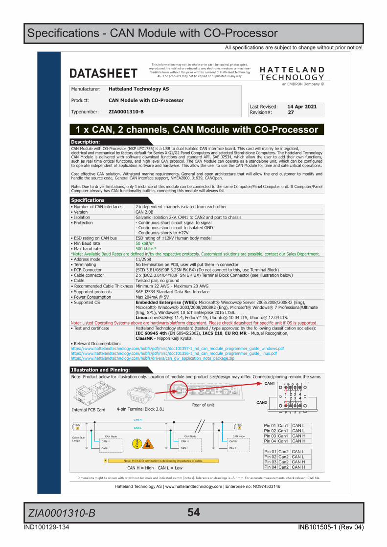
54IND100129-134
All specifications are subject to change without prior notice!
ZIA0001310-B
Specifications - CAN Module with CO-Processor
1/2
This information may not, in whole or in part, be copied, photocopied, reproduced, translated or reduced to any electronic medium or machine-readable form without the prior written consent of Hatteland Technology
AS. The products may not be copied or duplicated in any way.
Dimensions might be shown with or without decimals and indicated as mm [inches]. Tolerance on drawings is +/- 1mm. For accurate measurements, check relevant DWG fi le.
DATASHEET
Hatteland Technology AS | www.hattelandtechnology.com | Enterprise no: NO974533146
1 x CAN, 2 channels, CAN Module with CO-Processor
Manufacturer: Hatteland Technology AS
Product: CAN Module with CO-Processor
Typenumber: ZIA0001310-BLast Revised: 14 Apr 2021Revision#: 27
CAN Module with CO-Processor (NXP LPC1756) is a USB to dual isolated CAN interface board. This card will mainly be integrated,electrical and mechanical by factory default for Series X G1/G2 Panel Computers and selected Stand-alone Computers. The Hatteland Technology CAN Module is delivered with software download functions and standard API, SAE J2534, which allow the user to add their own functions, such as real time critical functions, and high level CAN protocol. The CAN Module can operate as a standalone unit, which can be configured to operate independent of application software and hardware. This allow the user to use the CAN Module for time and safe critical operations.
Cost effective CAN solution, Withstand marine requirements, General and open architecture that will allow the end customer to modify and handle the source code, General CAN interface support, NMEA2000, J1939, CANOpen.
Note: Due to driver limitations, only 1 instance of this module can be connected to the same Computer/Panel Computer unit. If Computer/Panel Computer already has CAN functionality built-in, connecting this module will always fail.
Description:
Specifications
Note: Product below for illustration only. Location of module and product size/design may differ. Connector/pinning remain the same.Illustration and Pinning:
4-pin Terminal Block 3.81
Pinout Assignments
69IND100241-13
Appendix
5-pin Digital Output Module“Safety Signal Relay”
3 A
DIGOUT
1 2 3 4 5
PIN 01 Out: 011 COM (Common Center Terminal)
PIN 02 N/C Not ConnectedNot in use
PIN 03 Out: 014 NO (Normally Open)
PIN 04 N/C Not Connected Not in use
PIN 05 Out: 012 NC (Normally Closed)
4+4 pin CAN I/O Module, 2 channelsType Number “HT 00254 OPT-A1”
3 A B
CAN1
CAN2
1 2 3 41 2 3 4
Pin 01 Can1 CAN LPin 02 Can1 CAN LPin 03 Can1 CAN HPin 04 Can1 CAN H
Pin 01 Can2 CAN LPin 02 Can2 CAN LPin 03 Can2 CAN HPin 04 Can2 CAN H
8-pin Digital Output / Input Module“Solid State Relay”
3 A
DIGOUT
DIGIN
1 2 3 4
1 2 3 4
Pin 01 Out: 041 Out +Pin 02 Out: 042 Out -
Pin 03 Out: 031 COM (Common Center Terminal) *
Pin 04 Out: 032 NO (Normally Open)** IEC 60950 Compliant, 48VDC
Pin 01 In: 052 +24VDCPin 02 In: 053 GND (Ground)Pin 03 In: 061 +24VDCPin 04 In: 062 +Input
10-pin Digital Output / Input & Serial Module“Mechanical Relay & COM (isolated RS-422/485)”
3 A
XIGOUT
SERI/O
1 2 3 4 51 2 3 4 5
PIN 01 Out: 021 COM (Common Center Terminal)
PIN 02 N/C Not Connected / Not usedPIN 03 Out: 024 NO (Normally Open)PIN 04 N/C Not Connected / Not usedPIN 05 Out: 022 NC (Normally Closed)
PIN 01 In: 71 Rx+ (Receive Data +)PIN 02 In: 72 Rx- (Receive Data -)PIN 03 Out: 73 Tx+ (Transmit Data +)PIN 04 Out: 74 Tx- (Transmit Data -)PIN 05 GND: 75 SGnd (Signal Ground)
10+10 pin RS-422 / RS-485 NMEA ModuleType Number “PCA100293-1”
3 A B
6 7 8 9 101 2 3 4 5
6 7 8 9 101 2 3 4 5
PIN 01 TxD- Transmit Data NegativePIN 02 TxD+ Transmit Data PositivePIN 03 GND Isolated GroundPIN 04 RxD- Receive Data NegativePIN 05 RxD+ Receive Data PositivePIN 06 TxD- Transmit Data NegativePIN 07 TxD+ Transmit Data PositivePIN 08 GND Isolated GroundPIN 09 RxD- Receive Data NegativePIN 10 RxD+ Receive Data Positive
RS-485 Half Duplex (2-wire) Confi guration:Connect TX and RX pair-wise:
TX- to RX-, TX+ to RX+.
*Note: The jumper for “force of transmitter” isopen by factory default. For some custom
models this jumper is preset to closed (active), in that case unit has to be opened and jumper
set to open to allow Half Duplex mode.
10-pin RS-422 / RS-485 Module“RS-422/RS-485 SCOM Buzzer”
1 2 B
2 4 6 8 101 3 5 7 9
PIN 01* RxD+ Receive Data PositivePIN 02 GND GroundPIN 03* RxD- Receive Data NegativePIN 04 +5V +5V OutPIN 05* TxD+ Transmit Data PositivePIN 06 BUZ- Buzzer Control NegativePIN 07* TxD- Transmit Data NegativePIN 08 BUZ+ Buzzer Control PositivePIN 09 GNDR Ground 100ΩPIN 10 GND Ground
*Pin 1,3,5,7 = RS-485 Full Duplex (4-wire)*Pin 5,7 = RS-485 Half Duplex (2-wire)
• Number of CAN interfaces 2 independent channels isolated from each other• Version CAN 2.0B• Isolation Galvanic isolation 2kV, CAN1 to CAN2 and port to chassis• Protection - Continuous short circuit signal to signal
- Continuous short circuit to isolated GND- Continuous shorts to ±27V
• ESD rating on CAN bus ESD rating of ±12kV Human body model• Min Baud rate 50 kbit/s*• Max baud rate 500 kbit/s**Note: Available Baud Rates are defined in/by the respective protocols. Customized solutions are possible, contact our Sales Department.• Address mode 11/29bit• Terminating No termination on PCB, user will put them in connector• PCB Connector (SCD 3.81/08/90F 3.2SN BK BX) (Do not connect to this, use Terminal Block)• Cable connector 2 x (BCZ 3.81/04/180F SN BK BX) Terminal Block Connector (see illustration below)• Cable Twisted pair, no ground• Recommended Cable Thickness Minimum 22 AWG - Maximum 20 AWG• Supported protocols SAE J2534 Standard Data Bus Interface• Power Consumption Max 204mA @ 5V• Supported OS Embedded Enterprise (WEE): Microsoft® Windows® Server 2003/2008/2008R2 (Eng),
Microsoft® Windows® 2003/2008/2008R2 (Eng), Microsoft® Windows® 7 Professional/Ultimate (Eng, SP1), Windows® 10 IoT Enterprise 2016 LTSB.Linux: openSUSE® 11.4, Fedora™ 15, Ubuntu® 10.04 LTS, Ubuntu® 12.04 LTS.
Note: Listed Operating Systems above are hardware/platform dependent. Please check datasheet for specific unit if OS is supported.• Test and certificate Hatteland Technology standard (tested / type approved by the following classification societies):
IEC 60945 4th (EN 60945:2002), IACS E10, EU RO MR - Mutual Recognition,ClassNK - Nippon Kaiji Kyokai
• Relevant Documentation:https://www.hattelandtechnology.com/hubfs/pdf/misc/doc101357-1_hd_can_module_programmer_guide_windows.pdfhttps://www.hattelandtechnology.com/hubfs/pdf/misc/doc101356-1_hd_can_module_programmer_guide_linux.pdfhttps://www.hattelandtechnology.com/hubfs/drivers/can_gw_application_note_package.zip
Rear of unitInternal PCB Card
CAN H = High - CAN L = Low
CAN Node
CAN H
CAN L*
Note: 110/120Ω termination is decided by impedance of cable.*
120Ω
*120Ω
Cable StubLength CAN H
CAN L
CAN Node
CAN H
CAN L
CAN Node
CAN H
CAN L
CAN1
CAN2
1 2 3 41 2 3 4
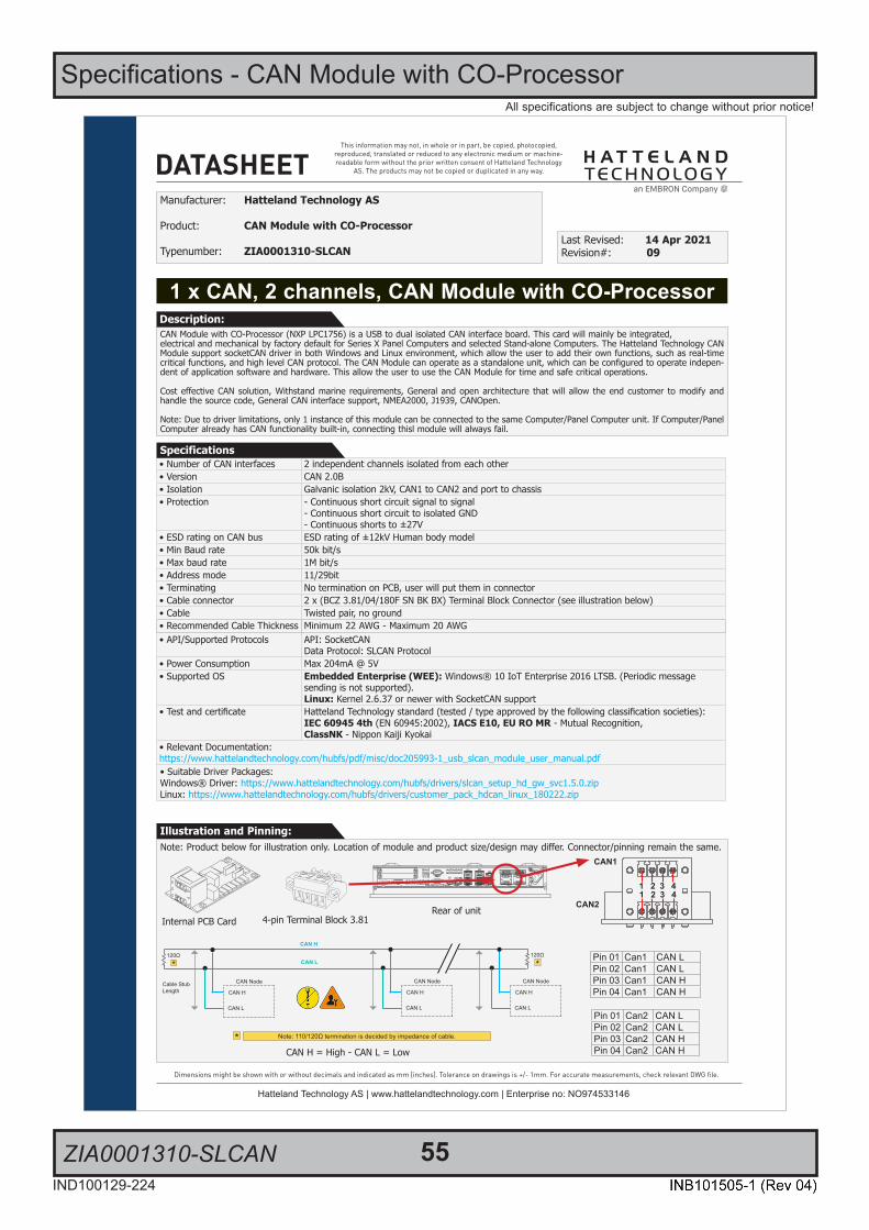
55IND100129-224
All specifications are subject to change without prior notice!
ZIA0001310-SLCAN
Specifications - CAN Module with CO-Processor
1/2
This information may not, in whole or in part, be copied, photocopied, reproduced, translated or reduced to any electronic medium or machine-readable form without the prior written consent of Hatteland Technology
AS. The products may not be copied or duplicated in any way.
Dimensions might be shown with or without decimals and indicated as mm [inches]. Tolerance on drawings is +/- 1mm. For accurate measurements, check relevant DWG fi le.
DATASHEET
Hatteland Technology AS | www.hattelandtechnology.com | Enterprise no: NO974533146
• Number of CAN interfaces 2 independent channels isolated from each other• Version CAN 2.0B• Isolation Galvanic isolation 2kV, CAN1 to CAN2 and port to chassis• Protection - Continuous short circuit signal to signal
- Continuous short circuit to isolated GND- Continuous shorts to ±27V
• ESD rating on CAN bus ESD rating of ±12kV Human body model• Min Baud rate 50k bit/s• Max baud rate 1M bit/s• Address mode 11/29bit• Terminating No termination on PCB, user will put them in connector• Cable connector 2 x (BCZ 3.81/04/180F SN BK BX) Terminal Block Connector (see illustration below)• Cable Twisted pair, no ground• Recommended Cable Thickness Minimum 22 AWG - Maximum 20 AWG• API/Supported Protocols API: SocketCAN
Data Protocol: SLCAN Protocol• Power Consumption Max 204mA @ 5V• Supported OS Embedded Enterprise (WEE): Windows® 10 IoT Enterprise 2016 LTSB. (Periodic message
sending is not supported).Linux: Kernel 2.6.37 or newer with SocketCAN support
• Test and certificate Hatteland Technology standard (tested / type approved by the following classification societies):IEC 60945 4th (EN 60945:2002), IACS E10, EU RO MR - Mutual Recognition,ClassNK - Nippon Kaiji Kyokai
• Relevant Documentation:https://www.hattelandtechnology.com/hubfs/pdf/misc/doc205993-1_usb_slcan_module_user_manual.pdf• Suitable Driver Packages:Windows® Driver: https://www.hattelandtechnology.com/hubfs/drivers/slcan_setup_hd_gw_svc1.5.0.zipLinux: https://www.hattelandtechnology.com/hubfs/drivers/customer_pack_hdcan_linux_180222.zip
1 x CAN, 2 channels, CAN Module with CO-Processor
Manufacturer: Hatteland Technology AS
Product: CAN Module with CO-Processor
Typenumber: ZIA0001310-SLCANLast Revised: 14 Apr 2021Revision#: 09
CAN Module with CO-Processor (NXP LPC1756) is a USB to dual isolated CAN interface board. This card will mainly be integrated,electrical and mechanical by factory default for Series X Panel Computers and selected Stand-alone Computers. The Hatteland Technology CAN Module support socketCAN driver in both Windows and Linux environment, which allow the user to add their own functions, such as real-time critical functions, and high level CAN protocol. The CAN Module can operate as a standalone unit, which can be configured to operate indepen-dent of application software and hardware. This allow the user to use the CAN Module for time and safe critical operations.
Cost effective CAN solution, Withstand marine requirements, General and open architecture that will allow the end customer to modify and handle the source code, General CAN interface support, NMEA2000, J1939, CANOpen.
Note: Due to driver limitations, only 1 instance of this module can be connected to the same Computer/Panel Computer unit. If Computer/Panel Computer already has CAN functionality built-in, connecting thisl module will always fail.
Description:
Specifications
Illustration and Pinning:Note: Product below for illustration only. Location of module and product size/design may differ. Connector/pinning remain the same.
CAN1
CAN2
1 2 3 41 2 3 4
4-pin Terminal Block 3.81
Pinout Assignments
69IND100241-13
Appendix
5-pin Digital Output Module“Safety Signal Relay”
3 A
DIGOUT
1 2 3 4 5
PIN 01 Out: 011 COM (Common Center Terminal)
PIN 02 N/C Not ConnectedNot in use
PIN 03 Out: 014 NO (Normally Open)
PIN 04 N/C Not Connected Not in use
PIN 05 Out: 012 NC (Normally Closed)
4+4 pin CAN I/O Module, 2 channelsType Number “HT 00254 OPT-A1”
3 A B
CAN1
CAN2
1 2 3 41 2 3 4
Pin 01 Can1 CAN LPin 02 Can1 CAN LPin 03 Can1 CAN HPin 04 Can1 CAN H
Pin 01 Can2 CAN LPin 02 Can2 CAN LPin 03 Can2 CAN HPin 04 Can2 CAN H
8-pin Digital Output / Input Module“Solid State Relay”
3 A
DIGOUT
DIGIN
1 2 3 4
1 2 3 4
Pin 01 Out: 041 Out +Pin 02 Out: 042 Out -
Pin 03 Out: 031 COM (Common Center Terminal) *
Pin 04 Out: 032 NO (Normally Open)** IEC 60950 Compliant, 48VDC
Pin 01 In: 052 +24VDCPin 02 In: 053 GND (Ground)Pin 03 In: 061 +24VDCPin 04 In: 062 +Input
10-pin Digital Output / Input & Serial Module“Mechanical Relay & COM (isolated RS-422/485)”
3 A
XIGOUT
SERI/O
1 2 3 4 51 2 3 4 5
PIN 01 Out: 021 COM (Common Center Terminal)
PIN 02 N/C Not Connected / Not usedPIN 03 Out: 024 NO (Normally Open)PIN 04 N/C Not Connected / Not usedPIN 05 Out: 022 NC (Normally Closed)
PIN 01 In: 71 Rx+ (Receive Data +)PIN 02 In: 72 Rx- (Receive Data -)PIN 03 Out: 73 Tx+ (Transmit Data +)PIN 04 Out: 74 Tx- (Transmit Data -)PIN 05 GND: 75 SGnd (Signal Ground)
10+10 pin RS-422 / RS-485 NMEA ModuleType Number “PCA100293-1”
3 A B
6 7 8 9 101 2 3 4 5
6 7 8 9 101 2 3 4 5
PIN 01 TxD- Transmit Data NegativePIN 02 TxD+ Transmit Data PositivePIN 03 GND Isolated GroundPIN 04 RxD- Receive Data NegativePIN 05 RxD+ Receive Data PositivePIN 06 TxD- Transmit Data NegativePIN 07 TxD+ Transmit Data PositivePIN 08 GND Isolated GroundPIN 09 RxD- Receive Data NegativePIN 10 RxD+ Receive Data Positive
RS-485 Half Duplex (2-wire) Confi guration:Connect TX and RX pair-wise:
TX- to RX-, TX+ to RX+.
*Note: The jumper for “force of transmitter” isopen by factory default. For some custom
models this jumper is preset to closed (active), in that case unit has to be opened and jumper
set to open to allow Half Duplex mode.
10-pin RS-422 / RS-485 Module“RS-422/RS-485 SCOM Buzzer”
1 2 B
2 4 6 8 101 3 5 7 9
PIN 01* RxD+ Receive Data PositivePIN 02 GND GroundPIN 03* RxD- Receive Data NegativePIN 04 +5V +5V OutPIN 05* TxD+ Transmit Data PositivePIN 06 BUZ- Buzzer Control NegativePIN 07* TxD- Transmit Data NegativePIN 08 BUZ+ Buzzer Control PositivePIN 09 GNDR Ground 100ΩPIN 10 GND Ground
*Pin 1,3,5,7 = RS-485 Full Duplex (4-wire)*Pin 5,7 = RS-485 Half Duplex (2-wire)
Rear of unitInternal PCB Card
CAN H = High - CAN L = Low
CAN Node
CAN H
CAN L*
Note: 110/120Ω termination is decided by impedance of cable.*
120Ω
*120Ω
Cable StubLength CAN H
CAN L
CAN Node
CAN H
CAN L
CAN Node
CAN H
CAN L

56IND100129-138
PCA100293-1
Specifications - NMEA / IEC COM Module RS-422 / RS-485
1/2
This information may not, in whole or in part, be copied, photocopied, reproduced, translated or reduced to any electronic medium or machine-readable form without the prior written consent of Hatteland Technology
AS. The products may not be copied or duplicated in any way.
Dimensions might be shown with or without decimals and indicated as mm [inches]. Tolerance on drawings is +/- 1mm. For accurate measurements, check relevant DWG fi le.
DATASHEET
Hatteland Technology AS | www.hattelandtechnology.com | Enterprise no: NO974533146 1/4
4 channel RS-422 / RS-485, NMEA / IEC COM Module
Manufacturer: Hatteland Technology AS
Product: 4 channel RS-422 / RS-485 COM module
Typenumber: PCA100293-1Last Revised: 25 Oct 2021Revision#: 29
The Hatteland Technology COM modules provide the system with quad independent COM channels. The module is attached to themotherboard via standard USB interface. Application software access the COM channels as standard COM devices, i.e. in the normal case is there no requirements for additional software development. This module will mainly be integrated, electrical and mechanical, in the final products, such as; Series X G1/G2 Panel Computers and selected Stand-alone Computers.
Description:
Internal USB to RS-485 / RS-422 isolated• Features - Independent channels (If card is replaced most OS will not change COM port number).
- Outputs are short circuits protected. Inputs are protected.- Driver strength are approved.- All channels is fully isolated, channel to channel and channel to chassis. - Classified towards IEC61162-1 and IEC61162-2.- Tested according to EN61162.- NMEA-183 Compliant.- All requirement for usage in ECDIS applications/systems is fulfilled.
• Absolute Max voltage applied to outputs -8V to +13V• Data Rate / Technical Data Output - Outputs 230kbps (Theoretically 400kbps).
- ±15kV ESD protection on all RS-485 signals. (Human Body Model - HBM)- Isolation rating = 2000VRMS, not intended for connection to live power nets.
• Transmitter enable mode - Standard mode is automatic.- Standard Mode will accept send by RTS, but will in fact ignore RTS.- Each channel have a overide jumper* which can be used to force the transmitter to always be active. See below and next page for details.
• Cable Connector Terminal Block 5-pin rows (MC 1,5/ 5-STF-3,81) (see illustration below)• Recommended Cable Thickness Minimum 22 AWG - Maximum 18 AWG• Power Consumption Max 347mA @ 5V• Supported Operating Systems (OS) Embedded Enterprise (WEE): Microsoft® Windows® Server 2003/2008/2008R2 (Eng),
Microsoft® Windows® 2003/2008/2008R2 (Eng), Microsoft® Windows® 7 Professional/Ultimate (Eng, SP1), Windows® 10 IoT Enterprise 2016 LTSB.Linux: Generic support for Kernel 3.0.0.19 or newer
• Drivers"https://www.hattelandtechnology.com/hubfs/pdf/misc/doc102080-1_usb-com_module_configuration.pdf""https://www.hattelandtechnology.com/hubfs/drivers/ht00262opt-a1_drivers.zip""https://www.hatteland-display.com/support_hardware_drivers_peripherals.php"Linux, please visit: http://www.ftdichip.com/Drivers/D2XX.htmNote: Listed Operating Systems above are hardware/platform dependent. Please check datasheet for specific unit if OS is supported.• Test and certificate Hatteland Technology standard,
(tested / type approved by the following classification societies):IEC 60945 4th (EN 60945:2002), IACS E10, EU RO MR - Mutual Recognition,ClassNK - Nippon Kaiji Kyokai
Note: Product below for illustration only. Location of module and product size/design may differ. Connector/pinning remain the same.Illustration and Pinning:
4 Ports (Virtual COM) identified in the Operating System (OS):COMx (A), COMx (B), COMx (C), COMx (D)**Configuration dependent, x = next available port number(s) OS.
RS-485 Half Duplex (2-wire, supports ECHO) Configuration:Connect TX and RX pair-wise: TX- to RX-, TX+ to RX+.
*Note: The jumper for “force of transmitter” is open by factory default. For some custommodels this jumper is preset to closed (active), in that case unit has to be opened and jumper set to open to allow Half Duplex mode.
5-pin Terminal Block 3.81
Pinout Assignments
69IND100241-13
Appendix
5-pin Digital Output Module“Safety Signal Relay”
3 A
DIGOUT
1 2 3 4 5
PIN 01 Out: 011 COM (Common Center Terminal)
PIN 02 N/C Not ConnectedNot in use
PIN 03 Out: 014 NO (Normally Open)
PIN 04 N/C Not Connected Not in use
PIN 05 Out: 012 NC (Normally Closed)
4+4 pin CAN I/O Module, 2 channelsType Number “HT 00254 OPT-A1”
3 A B
CAN1
CAN2
1 2 3 41 2 3 4
Pin 01 Can1 CAN LPin 02 Can1 CAN LPin 03 Can1 CAN HPin 04 Can1 CAN H
Pin 01 Can2 CAN LPin 02 Can2 CAN LPin 03 Can2 CAN HPin 04 Can2 CAN H
8-pin Digital Output / Input Module“Solid State Relay”
3 A
DIGOUT
DIGIN
1 2 3 4
1 2 3 4
Pin 01 Out: 041 Out +Pin 02 Out: 042 Out -
Pin 03 Out: 031 COM (Common Center Terminal) *
Pin 04 Out: 032 NO (Normally Open)** IEC 60950 Compliant, 48VDC
Pin 01 In: 052 +24VDCPin 02 In: 053 GND (Ground)Pin 03 In: 061 +24VDCPin 04 In: 062 +Input
10-pin Digital Output / Input & Serial Module“Mechanical Relay & COM (isolated RS-422/485)”
3 A
XIGOUT
SERI/O
1 2 3 4 51 2 3 4 5
PIN 01 Out: 021 COM (Common Center Terminal)
PIN 02 N/C Not Connected / Not usedPIN 03 Out: 024 NO (Normally Open)PIN 04 N/C Not Connected / Not usedPIN 05 Out: 022 NC (Normally Closed)
PIN 01 In: 71 Rx+ (Receive Data +)PIN 02 In: 72 Rx- (Receive Data -)PIN 03 Out: 73 Tx+ (Transmit Data +)PIN 04 Out: 74 Tx- (Transmit Data -)PIN 05 GND: 75 SGnd (Signal Ground)
10+10 pin RS-422 / RS-485 NMEA ModuleType Number “PCA100293-1”
3 A B
6 7 8 9 101 2 3 4 5
6 7 8 9 101 2 3 4 5
PIN 01 TxD- Transmit Data NegativePIN 02 TxD+ Transmit Data PositivePIN 03 GND Isolated GroundPIN 04 RxD- Receive Data NegativePIN 05 RxD+ Receive Data PositivePIN 06 TxD- Transmit Data NegativePIN 07 TxD+ Transmit Data PositivePIN 08 GND Isolated GroundPIN 09 RxD- Receive Data NegativePIN 10 RxD+ Receive Data Positive
RS-485 Half Duplex (2-wire) Confi guration:Connect TX and RX pair-wise:
TX- to RX-, TX+ to RX+.
*Note: The jumper for “force of transmitter” isopen by factory default. For some custom
models this jumper is preset to closed (active), in that case unit has to be opened and jumper
set to open to allow Half Duplex mode.
10-pin RS-422 / RS-485 Module“RS-422/RS-485 SCOM Buzzer”
1 2 B
2 4 6 8 101 3 5 7 9
PIN 01* RxD+ Receive Data PositivePIN 02 GND GroundPIN 03* RxD- Receive Data NegativePIN 04 +5V +5V OutPIN 05* TxD+ Transmit Data PositivePIN 06 BUZ- Buzzer Control NegativePIN 07* TxD- Transmit Data NegativePIN 08 BUZ+ Buzzer Control PositivePIN 09 GNDR Ground 100ΩPIN 10 GND Ground
*Pin 1,3,5,7 = RS-485 Full Duplex (4-wire)*Pin 5,7 = RS-485 Half Duplex (2-wire)
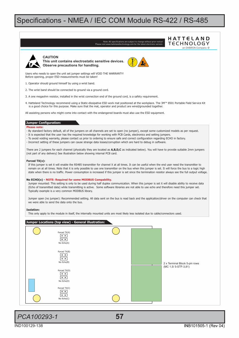
Specifications - NMEA / IEC COM Module RS-422 / RS-485
PCA100293-1 57IND100129-138
SPECIFICATIONS Note: All specifi cations are subject to change without prior notice!Please visit www.hattelandtechnology.com for the latest electronic version.
2/22/4
Please note:- By standard factory default, all of the jumpers on all channels are set to open (no jumper), except some customized models as per request.- It is expected that the user has the required knowledge for working with PCB Cards, electronics and setting jumpers.- To avoid voiding warranty, please contact us prior to ordering to ensure safe and correct configuration regarding ECHO in factory.- Incorrect setting of these jumpers can cause strange data losses/corruption which are hard to debug in software.
There are 2 jumpers for each channel (physically they are located as A,B,D,C as indicated below). You will have to provide suitable 2mm jumpers (not part of any delivery) See illustration below showing internal PCB card.
Forced TX(x): If this jumper is set it will enable the RS485 transmitter for channel X at all times. It can be useful when the end user need the transmitter to remain on at all times. Note that it is only possible to use one transmitter on the bus when this jumper is set. It will force the bus to a logic high state when there is no traffic. Power consumption is increased if this jumper is set since the termination resistor always see the full output voltage.
No ECHO(x) - NOTE: Required for some MODBUS Compability. Jumper mounted: This setting is only to be used during half duplex communication. When this jumper is set it will disable ability to receive data (Echo of transmitted data) while transmitting is active. Some software libraries are not able to use echo and therefore need this jumper set. Typically example is a very common MODBUS library.
Jumper open (no jumper): Recommended setting. All data sent on the bus is read back and the application/driver on the computer can check that we were able to send the data onto the bus.
Isolation: This only apply to the module in itself, the internally mounted units are most likely less isolated due to cable/connectors used.
Jumper Configuration:
Users who needs to open the unit set jumper settings will VOID THE WARRANTY!Before opening, proper ESD measurements must be taken!
1. Operator should ground himself by using a wrist band.
2. The wrist band should be connected to ground via a ground cord.
3. A one megaohm resistor, installed in the wrist connection end of the ground cord, is a safety requirement.
4. Hatteland Technology recommend using a Static-dissipative ESD work mat positioned at the workplace. The 3M™ 8501 Portable Field Service Kit is a good choice for this purpose. Make sure that the mat, operator and product are wired/grounded together.
All assisting persons who might come into contact with the endangered boards must also use the ESD equipment.
CAUTIONThis unit contains electrostatic sensitive devices.Observe precautions for handling.
Jumper Locations (top view) - General illustration:
Forced TX(C)
No Echo(C)
Forced TX(D)
No Echo(D)
Forced TX(B)
No Echo(B)
Forced TX(A)
No Echo(A)
2 x Terminal Block 5-pin rows(MC 1,5/ 5-STF-3,81)

Specifications - NMEA / IEC COM Module RS-422 / RS-485
PCA100293-1 58IND100129-138
SPECIFICATIONS Note: All specifi cations are subject to change without prior notice!Please visit www.hattelandtechnology.com for the latest electronic version.
2/23/4
5-pin Isolated NMEA COM“RS-422/RS-485”
5 4 3 2 1
PIN 01 TxD- Transmit Data NegativePIN 02 TxD+ Transmit Data PositivePIN 03 GND Isolated GroundPIN 04 RxD- Receive Data NegativePIN 05 RxD+ Receive Data Positive
*Pin 1,2,3,4=RS-422/485 Full Duplex (4-wire)*Pin 1+4, 2+5 = RS-485 Half Duplex (2-wire)
Connect TxD and RxD pair-wise: TxD- to RxD-, TxD+ to RxD+.
Note: Confi guration of options for ECHO of transmitted data and to force the transmitter to
always active is available in BIOS.
RS-422 / RS-485 FULL DUPLEX
120Ω
DE (Data Enable)
External Device
Termination Ω at end of cable
External Device
TX
TX RX
RX 120Ω
Termination Ω at end of cable
120Ω 120Ω
Termination Ω at end of cable
Termination Ω at end of cable
TX
External Device
TX
External Device
RX RX
Pin 1: TxD- (Z)
Pin 2: TxD+ (Y)
Pin 5: RxD+ (A)
Pin 4: RxD- (B)
1 112 2 24 4 4
5 55
*
Note: 120Ω termination on TX pins are rarely needed, unless cable is long or enviroment is very noisy.*
COM Ports are identifed in the Operating System(example Microsoft® Windows® 10) as:
COMx (A), COMx (B), COMx (C), COMx (D)*
*COM ports are not reserved nor locked by BIOS. x indicate a numeric number from 1-99. COM Port numbering may differ depending on OS used and customized solutions. Review the dedicated User Manual for actual unit, or use the Operating System functions to determine actual port numbering, if problems arise.
Our units are based on an isolated RS-485 interface with enhancements to meet NMEA standard. It is recommended connecting the ground wire since it will help protect the system in event of fast transient voltage and most likely also help improve signal integrity in the system.
For slow changing or DC offset our system will most likely work without the ground wire. If this wire is not connected, our units are more sensitive to fast transient voltage at the connectors. (The “isolated Ground” wire will help absorb this energy).
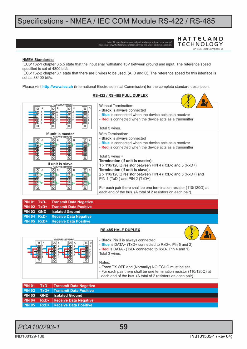
Specifications - NMEA / IEC COM Module RS-422 / RS-485
PCA100293-1 59IND100129-138
SPECIFICATIONS Note: All specifi cations are subject to change without prior notice!Please visit www.hattelandtechnology.com for the latest electronic version.
2/24/4
NMEA Standards:IEC61162-1 chapter 3.5.5 state that the input shall withstand 15V between ground and input. The reference speed specified is set at 4800 bit/s. IEC61162-2 chapter 3.1 state that there are 3 wires to be used. (A, B and C). The reference speed for this interface isset as 38400 bit/s.
Please visit http://www.iec.ch (International Electrotechnical Commission) for the complete standard description.
RS-422 / RS-485 FULL DUPLEX
Without Termination:- Black is always connected- Blue is connected when the device acts as a receiver- Red is connected when the device acts as a transmitter
Total 5 wires.If unit is master
R R R R
If unit is slave
R R R R
R R R R
With Termination:- Black is always connected- Blue is connected when the device acts as a receiver- Red is connected when the device acts as a transmitter
Total 5 wires +Termination (if unit is master):1 x 110/120 Ω resistor between PIN 4 (RxD-) and 5 (RxD+).Termination (if unit is slave):2 x 110/120 Ω resistor between PIN 4 (RxD-) and 5 (RxD+) andPIN 1 (TxD-) and PIN 2 (TxD+).
For each pair there shall be one termination resistor (110/120Ω) at each end of the bus. (A total of 2 resistors on each pair).
PIN 01 TxD- Transmit Data NegativePIN 02 TxD+ Transmit Data PositivePIN 03 GND Isolated GroundPIN 04 RxD- Receive Data NegativePIN 05 RxD+ Receive Data Positive
RS-485 HALF DUPLEX
- Black Pin 3 is always connected- Blue is DATA+ (TxD+ connected to RxD+. Pin 5 and 2)- Red is DATA - (TxD- connected to RxD-. Pin 4 and 1)Total 3 wires.
Notes: - Force TX OFF and (Normally) NO ECHO must be set.- For each pair there shall be one termination resistor (110/120Ω) at each end of the bus. (A total of 2 resistors on each pair).
PIN 01 TxD- Transmit Data NegativePIN 02 TxD+ Transmit Data PositivePIN 03 GND Isolated GroundPIN 04 RxD- Receive Data NegativePIN 05 RxD+ Receive Data Positive

60IND100129-169
All specifications are subject to change without prior notice!
PCA100297-1
Specifications - Isolated Digital Input/Output Module
1/2
This information may not, in whole or in part, be copied, photocopied, reproduced, translated or reduced to any electronic medium or machine-readable form without the prior written consent of Hatteland Technology
AS. The products may not be copied or duplicated in any way.
Dimensions might be shown with or without decimals and indicated as mm [inches]. Tolerance on drawings is +/- 1mm. For accurate measurements, check relevant DWG fi le.
DATASHEET
Hatteland Technology AS | www.hattelandtechnology.com | Enterprise no: NO974533146
4 x Isolated Input + 4 x Output, Digital IO Module
Manufacturer: Hatteland Technology AS
Product: Isolated Digital IO module (4 x Output + 4 x Input)
Typenumber: PCA100297-1Last Revised: 25 Oct 2021Revision#: 18
The Hatteland Technology DIO module provide the system with 4 isolated digital output and 4 isolated digital input. The module is attached to the motherboard via USB interface. Application software access the DIO channels via D2XX interface provided by the chip manufacturer, i.e. in the normal case is there no requirements for low level software development. This module will mainly be integrated, electrical and mechanical, in the final products, such as; Series X G1/G2 Panel Computers and selected Stand-alone Computers.
Description:
Digital Output Application Circuit• Features - Independent output channels, High side switch.
- Outputs are short circuits and overload protected.- Thermal shutdown.- Isolated towards chassis.- Output status/diagnostic feedback available for each output channel.- Outputs is rated for inductive and resistive loads.- Outputs is rated for driving small motors.- Classified towards IEC60945 and IEC60950.
• Maximum Ratings - Voltage: 9-36V continuously.- Load Current: 150mA.- Response time hardware for change of output state <20ms.- Response time hardware for diagnostic feedback <30ms.*- Worst case short circuit current (each channel) < 1.5A.
*Typical response time at system level: 200ms.
Above: High side switch concept
• Typical Application - Low Power control / relay control.- Medium power buzzer.- Indicator/signal lamps.
Digital Input Application Circuits• Features - Independent input channels.
- Fully isolated towards chassis and channel to channel.- Short circuit and reverse voltage protected.- Classified towards IEC60945 and IEC60950.
• Maximum Ratings - Input voltage 8-36V.- Response time hardware <10ms.- Input current < 20mA.

Specifications - Isolated Digital Input/Output Module
PCA100297-1 61IND100129-169
All specifications are subject to change without prior notice!
SPECIFICATIONS Note: All specifi cations are subject to change without prior notice!Please visit www.hattelandtechnology.com for the latest electronic version.
2/2
Supported Operating Systems (OS)Embedded Enterprise (WEE): - Microsoft® Windows® Server 2003/2008/2008R2 (Eng)- Microsoft® Windows® 2003/2008/2008R2 (Eng)- Microsoft® Windows® 7 Professional/Ultimate (Eng, SP1)- Windows® 10 IoT Enterprise 2016 LTSB- Windows® 10 IoT Enterprise 2019 LTSC
Linux:Kernel 3.0.0-19 or above
Note: Listed Operating Systems above are hardware/platform dependent. Please check datasheet for specific unit if OS is supported.
Currently supported D2XX DriversProcessor Architecture
Operating System (OS) Release Date (yyyy-mm-dd) x86 (32-bit) x64 (64-bit) Comments [Footnote]
Microsoft® Windows®* 2013-02-20 2.08.28 2.08.28 2.08.28 WHQL Certified [*1]Release Notes [*2]
Linux 2012-06-29 1.1.12 1.1.12 [*3]
*includes the following versions of the Microsoft® Windows® operating systems:Windows® XP, Windows® Server 2003, Windows® Vista, Windows® Server 2008, Windows® 7, Windows® Server 2008 R2 and Windows® 8.
For updates, please visit: http://www.ftdichip.com/Drivers/D2XX.htm
Footnotes: [*1] = http://www.ftdichip.com/Drivers/CDM/CDM20828_Setup.exe [*2] = http://www.ftdichip.com/Drivers/CDM/CDM%202%2008%2030%20Release%20Info%20for%208.1.rtf [*3] = http://www.ftdichip.com/Drivers/D2XX/Linux/ReadMe-linux.txt
Getting started, documentation and specific Hatteland Technology Library links:http://www.ftdichip.com/Support/Documents/ProgramGuides/D2XX_Programmer%27s_Guide(FT_000071).pdfhttps://www.hattelandtechnology.com/hubfs/pdf/misc/doc101781-1_programmer_guide_ht00273opt-a1.pdfhttps://www.hattelandtechnology.com/hubfs/drivers/dio_pca100297-1_ht00273opt-a1_package.zip
Additional• Cable connector 4 x 5-pin Terminal Block 3.81 connector (MC 1,5/ 5-STF-3,81) - see illustration below• Recommended Cable Thickness Minimum 22 AWG - Maximum 18 AWG• Test and certificate Hatteland Technology standard, (tested / type approved by the following classification societies):
IEC 60945 4th (EN 60945:2002), IACS E10, EU RO MR - Mutual Recognition,ClassNK - Nippon Kaiji Kyokai
• Safety IEC60950 The DIO module is intended to be used in control circuits and does therefore need external fuse to meet safety agency approvals.
Illustration and PinningNote: Product below for illustration only. Location of module and product size/design may differ. Connector/pinning/specifications remain the same.
5-pin Terminal Block 3.81Module A Module B
Pinout Assignments
70IND100241-13
Appendix
25-pin Female Parallel (Optional for selected computers)3 C
13 12 11 10 9 8 7 6 5 4 3 2 1
25 24 23 22 21 20 19 18 17 16 15 14Pin 01 STROBE This signal indicates to the printer that data at PD7..0 are valid.Pin 02 DATA0 Parallel data bus from PC board to printer. The data line are able to operate in PS/2 compatible bi-directional mode. Pin 03 DATA1 Same as Pin 02Pin 04 DATA2 Same as Pin 02Pin 05 DATA3 Same as Pin 02Pin 06 DATA4 Same as Pin 02Pin 07 DATA5 Same as Pin 02Pin 08 DATA6 Same as Pin 02Pin 09 DATA7 Same as Pin 02Pin 10 ACK Signal from printer indicating that the printer has received the data and is ready to accept further data.Pin 11 BUSY Signal from printer indicating that the printer cannot accept further data.Pin 12 PE Signal from printer indicating that the printer is out of paper.Pin 13 SELECT Signal from printer to indicate that the printer is selected.Pin 14 AUTO FEED This active low output causes the printer to add a line feed after each line printed.Pin 15 ERR# Signal from printer indicating that an error has been detected.Pin 16 INIT# This active low output initialises (resets) the printer. Pin 17 SLIN# Signal to select the printer sent from CPU board to printer. Pin 18 GND GroundPin 19 GND GroundPin 20 GND GroundPin 21 GND GroundPin 22 GND GroundPin 23 GND GroundPin 24 GND GroundPin 25 GND Ground
10+10 pin Isolated Digital Input/Output ModuleType Number “HT00268 OPT-A1”
3 C
Module A Module B
Module A Module BA1 External Power + A1 IN+[0]A2 N/C (Not Connected) A2 IN-[0]B1 External Power - (GND1) B1 IN+[1]B2 N/C (Not Connected) B2 IN-[1]O1 HS[0] O1 N/CC1 HS[1] C1 IN+[2]C2 N/C (Not Connected) C2 IN-[2]D1 HS[2] D1 IN+[3]D2 N/C (Not Connected) D2 IN-[3]O2 HS[3] O2 N/C
10-pin DisplayPort (DP) FemaleD
20 18 16 14 12 10 8 6 4 2
19 17 15 13 11 9 7 5 3 1
PIN 01 ML_Lane 0 (p) - Lane 0 (positive)PIN 02 GND - GroundPIN 03 ML_Lane 0 (n) - Lane 0 (negative)PIN 04 ML_Lane 1 (p) - Lane 1 (positive)PIN 05 GND - GroundPIN 06 ML_Lane 1 (n) - Lane 1 (negative)PIN 07 ML_Lane 2 (p) - Lane 2 (positive)PIN 08 GND - GroundPIN 09 ML_Lane 2 (n) - Lane 2 (negative)PIN 10 ML_Lane 3 (p) - Lane 3 (positive)PIN 11 GND - GroundPIN 12 ML_Lane 3 (n) - Lane 3 (negative)PIN 13* CONFIG1 - connected to Ground*PIN 14* CONFIG2 - connected to Ground*PIN 15 AUX CH (p) - Auxiliary Channel (positive)PIN 16 GND - GroundPIN 17 AUX CH (n) - Auxiliary Channel (negative)PIN 18 Hot Plug - Hot Plug DetectPIN 19 Return - Return for PowerPIN 20 DP_PWR - Power for connector (3.3 V 500 mA)
*Pins 13 and 14 may either be directly connected to ground or connected to ground through a pulldown device. This is the pinout for source-side connector, the sink-side connector pinout will have lanes 0–3 reversed in order; i.e., lane 3 will be on pin 1(n) and 3(p) while lane 0 will be on pin 10(n) and 12(p).

62IND100129-180
All specifications are subject to change without prior notice!
PCA100298-1
Specifications - LAN Module
1/2
This information may not, in whole or in part, be copied, photocopied, reproduced, translated or reduced to any electronic medium or machine-readable form without the prior written consent of Hatteland Technology
AS. The products may not be copied or duplicated in any way.
Dimensions might be shown with or without decimals and indicated as mm [inches]. Tolerance on drawings is +/- 1mm. For accurate measurements, check relevant DWG fi le.
DATASHEET
Hatteland Technology AS | www.hattelandtechnology.com | Enterprise no: NO974533146
Note: Product below for illustration only. Location of module and product size/design may differ. Connector/pinning remain the same.Illustration and Pinning:
2 x LAN RJ-45 - Internal Module
Manufacturer: Hatteland Technology AS
Product: Internal LAN Module RJ-45
Typenumber: PCA100298-1Last Revised: 10 Mar 2021Revision#: 11
Features:
The Hatteland Technology USB->Ethernet module provide the system with dual independent Ethernet ports. The module is connected internally to the motherboard via standard USB interfaces. Application software access the ethernet channels as standard ethernet devices, i.e. in the normal case is there no requirements for additional software development. This module can be integrated, electrical and mechanical, for the product such as Series X G1/G2 Panel Computers and selected Stand-alone Computers (Please check datasheet for your unit if PCA100298-1 is listed as part of Factory Options).
Description:
Internal 2 x USB to 2 x RJ-45• Connector 1kV Isolated RJ-45, 8-pin connector and pinning.
Each port as two LED reporting status of transmit/receive• Power Consumption Max 326mA @ 5V• Test and certificate Hatteland Technology standard, (tested / type approved by the following classification societies):
IEC 60945 4th (EN 60945:2002), IACS E10,EU RO MR - Mutual Recognition, ClassNK - Nippon Kaiji Kyokai
• Supported Operating Systems (OS)
Embedded Enterprise (WEE): Microsoft® Windows® Server 2003/2008/2008R2 (Eng), Microsoft® Windows® 2003/2008/2008R2 (Eng), Microsoft® Windows® 7 Professional/Ultimate (Eng, SP1), Windows® 10 IoT Enterprise 2016 LTSB.Linux: Kernel 3.0.0-64 or above
• Drivers http://www.asix.com.tw/products.php?op=pItemdetail&PItemID=105;71;101&PLine=71Note: Listed Operating Systems above are hardware/platform dependent. Please check datasheet for specific unit if OS is supported.
- USB 2.0 and 1.1 Standard Compliant.- Two internal USB ports are required.- IEEE 802.3 10Base-T/100 Base-T compatible.Note: Wake-on-lan is not supported.
8-pin RJ-45 10/100Mbps LAN/EthernetPCA100298-1 / HT 00274 OPT-A1
1 2 3 4 5 6 7 8
Pin 01 - TDP Transmit Diff erential Pair (Positive)Pin 02 - TDN Transmit Diff erential Pair (Negative)Pin 03 - RDP Receive Diff erential Pair (Positive)Pin 04 - NC Not ConnectedPin 05 - NC Not ConnectedPin 06 - RDN Receive Diff erential Pair (Negative)Pin 07 - NC Not ConnectedPin 08 - NC Not Connected

63IND100129-206
All specifications are subject to change without prior notice!
Specifications - Isolated COM Module RS-232
PCA100309-1
1/2
This information may not, in whole or in part, be copied, photocopied, reproduced, translated or reduced to any electronic medium or machine-readable form without the prior written consent of Hatteland Technology
AS. The products may not be copied or duplicated in any way.
Dimensions might be shown with or without decimals and indicated as mm [inches]. Tolerance on drawings is +/- 1mm. For accurate measurements, check relevant DWG fi le.
DATASHEET
Hatteland Technology AS | www.hattelandtechnology.com | Enterprise no: NO974533146
Note: Product below for illustration only. Location of module and product size/design may differ. Connector/pinning remain the same.
*Configuration dependent, x = next available port number(s) in operating system.
Illustration and Pinning:
2 channel COM RS-232, DB9M COM Module
Manufacturer: Hatteland Technology AS
Product: COM Module RS-232
Typenumber: PCA100309-1Last Revised: 10 Mar 2021Revision#: 06
Features:
The Hatteland Technology COM module provide the system with dual independent COM channels. The module is attached to themotherboard via standard USB interface. Application software access the COM channels as standard COM devices, i.e. in the normal case is there no requirements for additional software development. This module will mainly be integrated, electrical and mechanical, in the final product such as Series X G1/G2 Panel Computers and selected stand-alone computers.
Description:
Internal USB to 2 channel x RS-232 isolated• Features Both channels have support for all RS-232 DB-9 signals• Connector Standard RS-232 DB-9 male housing and pinning• Data Rate Tested from 300 up to 115200 Baud Rates• ESD Rating (IEC 1000-4-2 Air) (RS-232 I/Os)
±15 kV
• ESD Rating (IEC 1000-4-2 Contact) (RS-232 I/Os)
±8 kV
• Test and certificate Hatteland Technology standard,(tested / type approved by the following classification societies):IEC 60945 4th (EN 60945:2002), IACS E10, EU RO MR - Mutual Recognition,ClassNK - Nippon Kaiji Kyokai
• Supported Operating Systems (OS) Embedded Enterprise (WEE): Microsoft® Windows® Server 2003/2008/2008R2 (Eng), Microsoft® Windows® 2003/2008/2008R2 (Eng), Microsoft® Windows® 7 Professional/Ultimate (Eng, SP1), Windows® 10 IoT Enterprise 2016 LTSB.Linux: Kernel 3.0.0-64 or above
• Drivers/Documentation https://www.hattelandtechnology.com/hubfs/drivers/pca100390-1_drivers.zipNote: Listed Operating Systems above are hardware/platform dependent. Please check datasheet for specific unit if OS is supported.
- 2 independent channels (If a card is replaced most operating system will not change COM port number)- Outputs are short circuits protected
1 2 3 4 5
6 7 8 9
2 Ports available in Operating System as: COMx (A)*, COMx (B)*
Pinout Assignments
67IND100241-13
Appendix
Analog RGB/VGA, 15-pin DSUB High Density Female1 2 3 A B
5 4 3 2 1
15 14 13 12 11
10 9 8 7 6
PIN 01 RED Red, analogPIN 02 GREEN Green, analogPIN 03 BLUE Blue, analogPIN 04 ID2/RES Reserved for monitor ID bit 2 (grounded)PIN 05 GND Digital groundPIN 06 RED_RTN Analog ground redPIN 07 GREEN_RTN Analog ground greenPIN 08 BLUE_RTN Analog ground bluePIN 09 KEY/PWR +5V power supply for DDC (optional)PIN 10 GND Digital groundPIN 11 ID0/RES Reserved for monitor ID bit 0 (grounded)PIN 12 ID1/SDA DDC serial dataPIN 13 HSYNC. Horizontal sync or composite sync, inputPIN 14 VSYNC. Vertical sync, inputPIN 15 ID3/SCL DDC serial clock
Serial COM RS-232 non-isolated, 9-pin DSUB Female1 2 B
5 4 3 2 1
9 8 7 6
PIN 01 BUZ+ Buzzer Control Positive*PIN 02 TxD Transmit DataPIN 03 RxD Receive DataPIN 04 DTR Data Terminal ReadyPIN 05 GND GroundPIN 06 DSR Data Set ReadyPIN 07 RTS Request To SendPIN 08 CTS Clear To SendPIN 09 BUZ- Buzzer Control Negative*
*Wake On Ring is not enabled
Serial COM RS-485/RS-422, 9-pin DSUB Male“Full Duplex Mode*
3 B
1 2 3 4 5
6 7 8 9PIN 01 TxD- Transmit Data NegativePIN 02 TxD+ Transmit Data PositivePIN 03 RxD+ Receive Data PositivePIN 04 RxD- Receive Data NegativePIN 05 GND Signal GroundPIN 06 N/C No internal connectionPIN 07 N/C No internal connectionPIN 08 N/C No internal connectionPIN 09 N/C No internal connection
*Master only. ECHO not supported.
Serial COM RS-485/RS-422, 9-pin DSUB Male“Half Duplex Mode*
3 B
1 2 3 4 5
6 7 8 9PIN 01 Res. Reserved, do not connectPIN 02 Res. Reserved, do not connectPIN 03 Data+ Data PositivePIN 04 Data- Data NegativePIN 05 GND Signal GroundPIN 06 N/C No internal connectionPIN 07 N/C No internal connectionPIN 08 N/C No internal connectionPIN 09 N/C No internal connection
*ECHO not supported.Half Duplex Confi guration: Via Hatteland Display API.
Flow control: Via RTS signal (controlled by user application).
Serial COM RS-232 non-isolated, 9-pin DSUB Male3 B
1 2 3 4 5
6 7 8 9
PIN 01 DCD Data Carrier DetectPIN 02 RxD Receive DataPIN 03 TxD Transmit DataPIN 04 DTR Data Terminal ReadyPIN 05 GND Signal GroundPIN 06 DSR Data Set ReadyPIN 07 RTS Request To SendPIN 08 CTS Clear To SendPIN 09 RI Ring Indicator
COM Module RS-232 - 4 x ports, 9-pin DSUB MaleType Number “PCA100294-1”
3 A B
B
A
D
C
1 2 3 4 5
6 7 8 9
PIN 01 DCD Data Carrier DetectPIN 02 RxD Receive DataPIN 03 TxD Transmit DataPIN 04 DTR Data Terminal ReadyPIN 05 GND Signal GroundPIN 06 DSR Data Set ReadyPIN 07 RTS Request To SendPIN 08 CTS Clear To SendPIN 09 RI Ring Indicator
A B
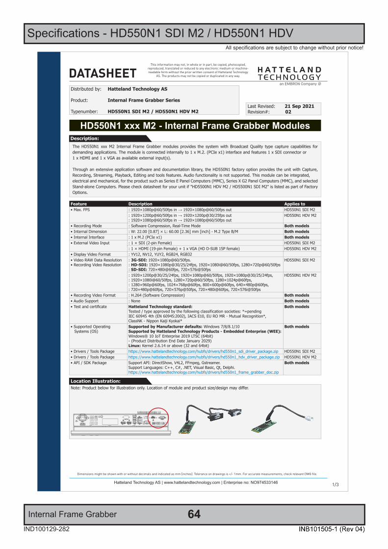
64IND100129-282
All specifications are subject to change without prior notice!
Specifications - HD550N1 SDI M2 / HD550N1 HDV
Internal Frame Grabber
1/2
This information may not, in whole or in part, be copied, photocopied, reproduced, translated or reduced to any electronic medium or machine-readable form without the prior written consent of Hatteland Technology
AS. The products may not be copied or duplicated in any way.
Dimensions might be shown with or without decimals and indicated as mm [inches]. Tolerance on drawings is +/- 1mm. For accurate measurements, check relevant DWG fi le.
DATASHEET
Hatteland Technology AS | www.hattelandtechnology.com | Enterprise no: NO974533146 1/3
The HD550N1 xxx M2 Internal Frame Grabber modules provides the system with Broadcast Quality type capture capabilities for demanding applications. The module is connected internally to 1 x M.2. (PCIe x1) interface and features 1 x SDI connector or1 x HDMI and 1 x VGA as available external input(s).
Through an extensive application software and documentation library, the HD550N1 factory option provides the unit with Capture, Recording, Streaming, Playback, Editing and tools features. Audio functionality is not supported. This module can be integrated,electrical and mechanical, for the product such as Series E Panel Computers (MMC), Series X G2 Panel Computers (MMC), and selected Stand-alone Computers. Please check datasheet for your unit if "HD5500N1 HDV M2 / HD5500N1 SDI M2" is listed as part of Factory Options.
HD550N1 xxx M2 - Internal Frame Grabber Modules
Distributed by: Hatteland Technology AS
Product: Internal Frame Grabber Series
Typenumber: HD550N1 SDI M2 / HD550N1 HDV M2Last Revised: 21 Sep 2021Revision#: 02
Description:
Feature Description Applies to• Max. FPS : 1920×1080p@60/50fps in → 1920×1080p@60/50fps out HD550N1 SDI M2
: 1920×1200p@60/50fps in → 1920×1200p@30/25fps out: 1920×1080p@60/50fps in → 1920×1080p@60/50fps out
HD550N1 HDV M2
• Recording Mode : Software Compression, Real-Time Mode Both models• Internal Dimension : W: 22.00 [0.87] × L: 60.00 [2.36] mm [inch] - M.2 Type B/M Both models• Internal Interface : 1 x M.2 (PCIe x1) Both models• External Video Input : 1 × SDI (2-pin Female) HD550N1 SDI M2
: 1 × HDMI (19-pin Female) + 1 x VGA (HD D-SUB 15P female) HD550N1 HDV M2• Display Video Format : YV12, NV12, YUY2, RGB24, RGB32• Video RAW Data Resolution• Recording Video Resolution
: 3G-SDI: 1920×1080p@60/50fps.: HD-SDI: 1920×1080p@30/25/24fps, 1920×1080i@60/50fps, 1280×720p@60/50fps: SD-SDI: 720×480i@60fps, 720×576i@50fps
HD550N1 SDI M2
: 1920×1200p@30/25/24fps, 1920×1080p@60/50fps, 1920×1080p@30/25/24fps,: 1920×1080i@60/50fps, 1280×720p@60/50fps, 1280×1024p@60fps,: 1280×960p@60fps, 1024×768p@60fps, 800×600p@60fps, 640×480p@60fps,: 720×480p@60fps, 720×576p@50fps, 720×480i@60fps, 720×576i@50fps
HD550N1 HDV M2
• Recording Video Format : H.264 (Software Compression) Both models• Audio Support : None Both models• Test and certificate Hatteland Technology standard:
Tested / type approved by the following classification societies: *=pendingIEC 60945 4th (EN 60945:2002), IACS E10, EU RO MR - Mutual Recognition*,ClassNK - Nippon Kaiji Kyokai*
Both models
• Supported Operating Systems (OS)
Supported by Manufacturer defaults: Windows 7/8/8.1/10Supported by Hatteland Technology Products - Embedded Enterprise (WEE):Windows® 10 IoT Enterprise 2019 LTSC (64bit)- (Product Distribution End Date January 2029)Linux: Kernel 2.6.14 or above (32 and 64bit)
Both models
• Drivers / Tools Package https://www.hattelandtechnology.com/hubfs/drivers/hd550n1_sdi_driver_package.zip HD550N1 SDI M2• Drivers / Tools Package https://www.hattelandtechnology.com/hubfs/drivers/hd550n1_hdv_driver_package.zip HD550N1 HDV M2• API / SDK Package Support API: DirectShow, V4L2, FFmpeg, Gstreamer.
Support Languages: C++, C#, .NET, Visual Basic, Qt, Delphi.https://www.hattelandtechnology.com/hubfs/drivers/hd550n1_frame_grabber_doc.zip
Both models
Note: Product below for illustration only. Location of module and product size/design may differ.Location Illustration:
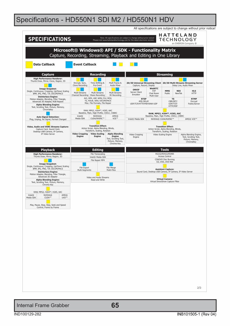
Specifications - HD550N1 SDI M2 / HD550N1 HDV
Internal Frame Grabber 65IND100129-282
All specifications are subject to change without prior notice!
SPECIFICATIONS Note: All specifi cations are subject to change without prior notice!Please visit www.hattelandtechnology.com for the latest electronic version.
2/22/3
CaptureHigh Performance Renderer:
Thumb Draw, Mirror, Clone, Region, 3D
Image Snapshot: Single, Continuous, Cropping, Up/Down Scaling
BMP, JPG, PNG, TIF, DICOM/PACSDeinterlace Engine:
Motion Adapter, Blending, Filter Triangle,Advanced 3D Adapter, RGB Repack
Alpha Blending Engine:Text, Scrolling Text, Picture, Memory,
ChromaKey
Auto Signal Detection: Plug, Unplug, No Signal, Format Changed
Video, Audio and VANC Streams Capture:
Capture Card, Sound Card, Desktop USB Camera, IP Camera,
IP Video Server
Microsoft® Windows® API / SDK - Functionality MatrixCapture, Recording, Streaming, Playback and Editing in One Library
Data Callback Event Callback
Recording
Encrypt, Sync,Clone Recording
Time Shifting &Pre-Event
Multi-Tracks &Audio Mixer
Multi-StreamsChannel Recording
Multi-StreamsShare Recording
Multi-Streams3D Recording
AVI, MP4, ASF, WMV, FLV, MOV,TS, M3U8, WAV, DICOM/PACSMisc. File Formats, File Repair
RAW, MPG2, H2643D, H265, AACBaseline, Main, High Profile, CAVLC, CABAC
Intel®Media SDK
NVIDIA® CUDA/NVENC™
AMD®VCE™
Transition Effect:Action Script, Alpha Blending, Blinds,
Transform, Scaling, RotationVideo Cropping
EngineVideo Scaling
EngineAlpha Blending
EngineText, Scrolling Text, Picture, Memory,
Chroma Key
Streaming
2D/3D Universal Streaming ClientCapture, Record, Display
2D/3D Multi-Streams Streaming Server Delay Live, Audio Mixer
ONVIFServer Client
Emulator
WebRTCP2P
Chat RoomMulti-User
MMSPublic
NDINewTek
HLSHTTP
RTSP4MS DELAY
UDP/TCP/HTTP/MIP/RAW-UDP
TSCBR/SRT/UDP/TCP/HTTP/MIP
RTMPEncrypt
Public/Server
RAW, MPG2, H2643D, H265, AACBaseline, Main, High Profile, CAVLC, CABAC
Intel® Media SDK NVIDIA® CUDA/NVENC™ AMD® VCE™
Transition Effect:Action Script, Alpha Blending, Blinds,
Transform, Scaling, RotationVideo Cropping
EngineVideo Scaling Engine Alpha Blending Engine,
Text, Scrolling Text,Picture, Memory,
ChromaKey
PlaybackHigh Performance Renderer:Thumb Draw, Mirror, Region, 3D
Image Snapshot: Single, Continuous, Cropping, Up/Down Scaling
BMP, JPG, PNG, TIF, DICOM/PACSDeinterlace Engine:
Motion Adapter, Blending, Filter Triangle,Advanced 3D Adapter
Alpha Blending Engine:Text, Scrolling Text, Picture, Memory,
Chroma Key
RAW, MPG2, H2643D, H265, AACIntel®
Media SDKNVIDIA® CUDA™
AMD®UVD™
Play, Pause, Stop, Step, Seek and Speed
Control, Frame by Frame
EditingFile Transcoding
Intel® Media SDKFile Repair MP4
File ExportMulti-Segments
File MergeMulti-Files
Video and Audio StreamsRead and Write
ToolsRS232/RS422/RS485
Access ControlCD&DVD Disc Burning
CD, DVD, DVD-RW
Assistant Capture:Sound Card, Desktop USB Camera, IP Camera, IP Video Server
Virtual Camera:Virtual DirectShow Capture Filter
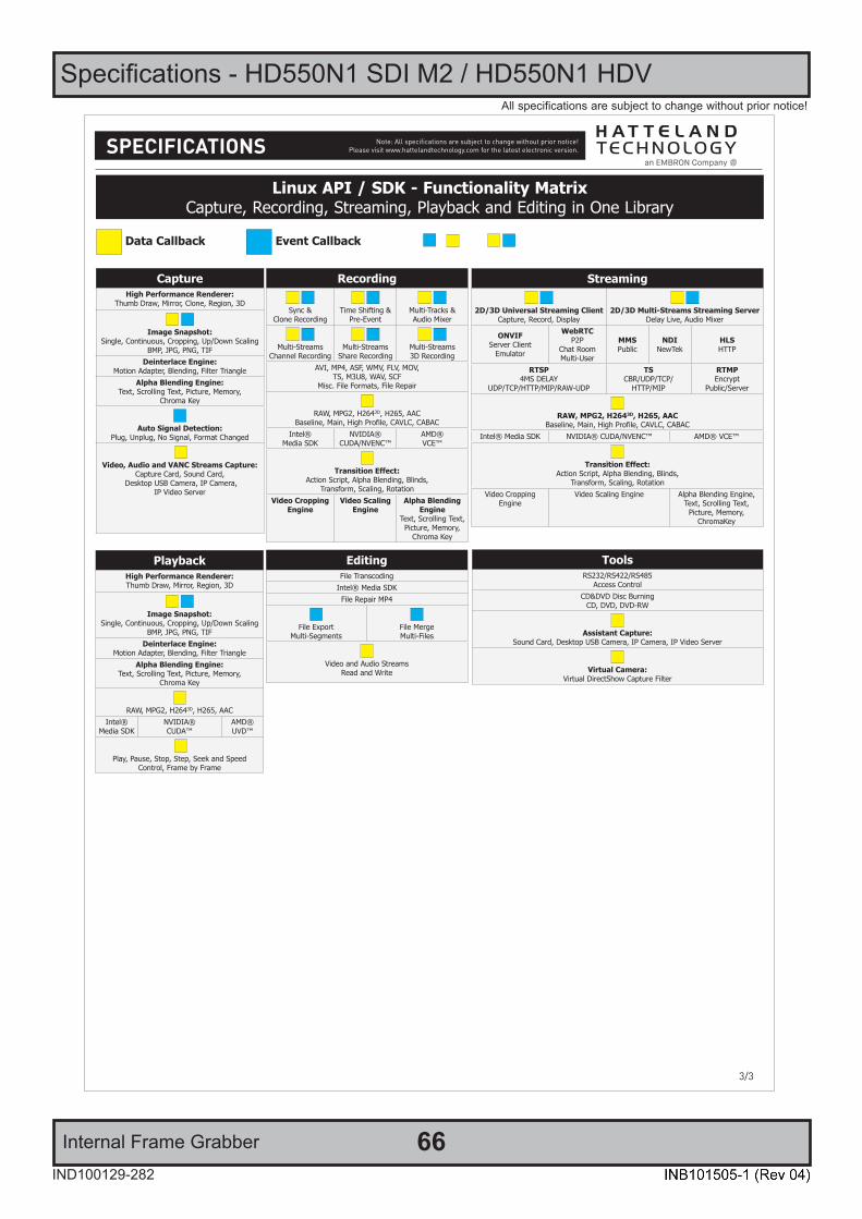
Specifications - HD550N1 SDI M2 / HD550N1 HDV
Internal Frame Grabber 66IND100129-282
All specifications are subject to change without prior notice!
SPECIFICATIONS Note: All specifi cations are subject to change without prior notice!Please visit www.hattelandtechnology.com for the latest electronic version.
2/23/3
CaptureHigh Performance Renderer:
Thumb Draw, Mirror, Clone, Region, 3D
Image Snapshot: Single, Continuous, Cropping, Up/Down Scaling
BMP, JPG, PNG, TIFDeinterlace Engine:
Motion Adapter, Blending, Filter TriangleAlpha Blending Engine:
Text, Scrolling Text, Picture, Memory,Chroma Key
Auto Signal Detection: Plug, Unplug, No Signal, Format Changed
Video, Audio and VANC Streams Capture:
Capture Card, Sound Card, Desktop USB Camera, IP Camera,
IP Video Server
Linux API / SDK - Functionality MatrixCapture, Recording, Streaming, Playback and Editing in One Library
Data Callback Event Callback
Recording
Sync &Clone Recording
Time Shifting &Pre-Event
Multi-Tracks &Audio Mixer
Multi-StreamsChannel Recording
Multi-StreamsShare Recording
Multi-Streams3D Recording
AVI, MP4, ASF, WMV, FLV, MOV,TS, M3U8, WAV, SCF
Misc. File Formats, File Repair
RAW, MPG2, H2643D, H265, AACBaseline, Main, High Profile, CAVLC, CABAC
Intel®Media SDK
NVIDIA® CUDA/NVENC™
AMD®VCE™
Transition Effect:Action Script, Alpha Blending, Blinds,
Transform, Scaling, RotationVideo Cropping
EngineVideo Scaling
EngineAlpha Blending
EngineText, Scrolling Text, Picture, Memory,
Chroma Key
Streaming
2D/3D Universal Streaming ClientCapture, Record, Display
2D/3D Multi-Streams Streaming Server Delay Live, Audio Mixer
ONVIFServer Client
Emulator
WebRTCP2P
Chat RoomMulti-User
MMSPublic
NDINewTek
HLSHTTP
RTSP4MS DELAY
UDP/TCP/HTTP/MIP/RAW-UDP
TSCBR/UDP/TCP/
HTTP/MIP
RTMPEncrypt
Public/Server
RAW, MPG2, H2643D, H265, AACBaseline, Main, High Profile, CAVLC, CABAC
Intel® Media SDK NVIDIA® CUDA/NVENC™ AMD® VCE™
Transition Effect:Action Script, Alpha Blending, Blinds,
Transform, Scaling, RotationVideo Cropping
EngineVideo Scaling Engine Alpha Blending Engine,
Text, Scrolling Text,Picture, Memory,
ChromaKey
PlaybackHigh Performance Renderer:Thumb Draw, Mirror, Region, 3D
Image Snapshot: Single, Continuous, Cropping, Up/Down Scaling
BMP, JPG, PNG, TIFDeinterlace Engine:
Motion Adapter, Blending, Filter TriangleAlpha Blending Engine:
Text, Scrolling Text, Picture, Memory,Chroma Key
RAW, MPG2, H2643D, H265, AACIntel®
Media SDKNVIDIA® CUDA™
AMD®UVD™
Play, Pause, Stop, Step, Seek and Speed
Control, Frame by Frame
EditingFile Transcoding
Intel® Media SDKFile Repair MP4
File ExportMulti-Segments
File MergeMulti-Files
Video and Audio StreamsRead and Write
ToolsRS232/RS422/RS485
Access ControlCD&DVD Disc Burning
CD, DVD, DVD-RW
Assistant Capture:Sound Card, Desktop USB Camera, IP Camera, IP Video Server
Virtual Camera:Virtual DirectShow Capture Filter
67
Specifications Accessories

68IND100129-133
Specifications - JH C01MF A-A
1/2
This information may not, in whole or in part, be copied, photocopied, reproduced, translated or reduced to any electronic medium or machine-readable form without the prior written consent of Hatteland Technology
AS. The products may not be copied or duplicated in any way.
Dimensions might be shown with or without decimals and indicated as mm [inches]. Tolerance on drawings is +/- 1mm. For accurate measurements, check relevant DWG fi le.
DATASHEET
Hatteland Technology AS | www.hattelandtechnology.com | Enterprise no: NO974533146
USB Cable
Manufacturer: Hatteland Technology AS
Product: USB Cable 1m
Type: JH C01MF A-ALast Revised: 16 Apr 2019Revision#: 08
USB Cable (Type A plug to Chassis mount Type A receptacle) suitable for installations that feature a secure fastening connection from external equipment with standard Type A ports to all Hatteland Technology computers and panel computers with standard USB Type A ports. RoHS Compliant.
Description:
Specifications• Waterproof Rate : IP67. (No Ingress of dust / Protected against harmful effects caused in 1 meter water within 30 minutes)• Temperature Range : -20°C to +80°C• Max Panel Thickness : 7.0mm (Without Cap Chain)• Materials : Housing: Nylon, Black
: Conn.1: USB2.0-A, Jack: Conn.2: USB2.0-A, Plug: Cap: Nylon, Black
• Cable : 1m, UL2725 USB2.0, 28AWG*1P+24AWG*2C+AL+D+B, PVC Jacket, UV Resistant, Black 0D=ø5.5mm• Receptacle Connector : USB-A Plastic C3 Panel Jack screw with pig tail (GT116300-30)• Type Approval / Testing : Hatteland Technology standard, (tested / type approved by the following classification societies):
IEC 60945 4th (EN 60945:2002), IACS E10, EU RO MR - Mutual Recognition• Included with delivery : 1 x 218-N28 - Cable tie fastener w/glue Panuit 30
: 1 x B2-100 Black Cable tie 2,5x100mm: 1 x GTC Waterproof Mating Cap P/N GT1C533122
ACCESSORY
FRONT VIEW SIDE / TOP VIEW
WIRING DIAGRAM
FRONT VIEW
MATING CAP GT1C533122
PIN ASSIGNMENTS FRONT VIEW RECOMMENDED PANEL CUTOUT
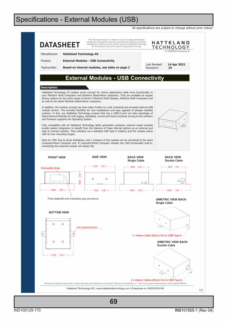
Specifications - External Modules (USB)
69IND100129-170
All specifications are subject to change without prior notice!
Specifications - External Modules (USB)
1/2
This information may not, in whole or in part, be copied, photocopied, reproduced, translated or reduced to any electronic medium or machine-readable form without the prior written consent of Hatteland Technology
AS. The products may not be copied or duplicated in any way.
Dimensions might be shown with or without decimals and indicated as mm [inches]. Tolerance on drawings is +/- 1mm. For accurate measurements, check relevant DWG fi le.
DATASHEET
Hatteland Technology AS | www.hattelandtechnology.com | Enterprise no: NO974533146
Hatteland Technology IO module series concept for marine applications adds more functionality to your Maritime Multi Computers and Maritime Stand-Alone computers. They are available as regular factory options for the entire range of Series X Maritime Multi Displays, Maritime Multi Computers and as well as the latest Maritime Stand-Alone computers.
In addition, the module concept has been taken further to a self contained and encased external USB module version. This provides flexibility for new installations and easy upgrade of already installed systems. In fact, any Hatteland Technology product that has a USB2.0 port can take advantage of these External Modules for both legacy, obsoleted, current and future products as long as the software and firmware supports the Operating System.
Fully compatible with all Hatteland Technology latest generation products, external cased modules enable system integrators to benefit from the features of these internal options as an external and easy to connect solution. They interface via a standard USB Type A Cable(s) and the chassis comes with its own mounting hinges.
Note for CAN: Due to driver limitations, only 1 instance of this module can be connected to the same Computer/Panel Computer unit. If Computer/Panel Computer already has CAN functionality built-in, connecting this external module will always fail.
External Modules - USB Connectivity
Manufacturer: Hatteland Technology AS
Product: External Modules - USB Connectivity
Typenumber: Based on internal modules, see table on page 2Last Revised: 14 Apr 2021Revision#: 19
Description:
FRONT VIEW SIDE VIEW BACK VIEWSIngle Cable
BOTTOM VIEW
DIMETRIC VIEW BACKSingle Cable
Front plate/silk print indicating type and pinout
BACK VIEWDouble Cable
DIMETRIC VIEW BACKDouble Cable
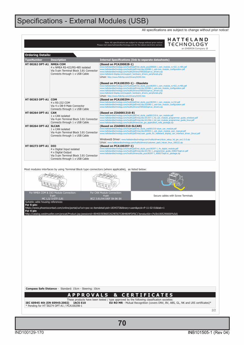
Specifications - External Modules (USB)
70IND100129-170
All specifications are subject to change without prior notice!
SPECIFICATIONS Note: All specifi cations are subject to change without prior notice!Please visit www.hattelandtechnology.com for the latest electronic version.
2/2
TypeNumber Description Internal Specifications (link to separate datasheets)HT 00262 OPT-A1 NMEA COM
4 x NMEA RS-422/RS-485 isolatedVia 5-pin Terminal Block 3.81 ConnectorConnects through 1 x USB Cable
(Based on PCA200828-1)www.hattelandtechnology.com/hubfs/pdf/ind_ds/ds_pca200828-1_com_module_rs-422_rs-485.pdfwww.hattelandtechnology.com/hubfs/pdf/misc/doc102080-1_usb-com_module_configuration.pdfwww.hattelandtechnology.com/hubfs/drivers/ht00262opt-a1_drivers.zipwww.hatteland-display.com/support_hardware_drivers_peripherals.phpLinux: http://www.ftdichip.com/Drivers/D2XX.htm
(Based on PCA100293-1) - Obsoletewww.hattelandtechnology.com/hubfs/pdf/ind_ds/ds_pca100293-1_com_module_rs-422_rs-485.pdfwww.hattelandtechnology.com/hubfs/pdf/misc/doc102080-1_usb-com_module_configuration.pdfwww.hattelandtechnology.com/hubfs/drivers/ht00262opt-a1_drivers.zipwww.hatteland-display.com/support_hardware_drivers_peripherals.phpLinux: http://www.ftdichip.com/Drivers/D2XX.htm
HT 00263 OPT-A1 COM4 x RS-232 COMVia 4 x DB-9 Male ConnectorConnects through 1 x USB Cable
(Based on PCA100294-1)www.hattelandtechnology.com/hubfs/pdf/ind_ds/ds_pca100294-1_com_module_rs-232.pdfwww.hattelandtechnology.com/hubfs/pdf/misc/doc102080-1_usb-com_module_configuration.pdfwww.hattelandtechnology.com/hubfs/drivers/ht00263opt-a1_drivers.zip
HT 00264 OPT-A1 CAN1 x CAN isolatedVia 4-pin Terminal Block 3.81 ConnectorConnects through 1 x USB Cable
(Based on ZIA0001310-B)www.hattelandtechnology.com/hubfs/pdf/ind_ds/ds_zia0001310-b_can_module.pdfwww.hattelandtechnology.com/hubfs/pdf/misc/doc101357-1_hd_can_module_programmer_guide_windows.pdfwww.hattelandtechnology.com/hubfs/pdf/misc/doc101356-1_hd_can_module_programmer_guide_linux.pdfwww.hattelandtechnology.com/hubfs/drivers/can_gw_application_note_package.zip
HT 00264 OPT-A2 SLCAN1 x CAN isolatedVia 4-pin Terminal Block 3.81 ConnectorConnects through 1 x USB Cable
(Based on ZIA0001310-SLCAN)www.hattelandtechnology.com/hubfs/pdf/ind_ds/ds_zia0001310-slcan_can_module.pdfwww.hattelandtechnology.com/hubfs/pdf/misc/doc205993-1_usb_slcan_module_user_manual.pdfwww.hattelandtechnology.com/hubfs/pdf/misc/user_guide_for_hatteland_display_can_interface_driver_(linux).pdf
Windows® Driver: www.hattelandtechnology.com/hubfs/drivers/slcan_setup_hd_gw_svc1.5.0.zipLinux: www.hattelandtechnology.com/hubfs/drivers/customer_pack_hdcan_linux_180222.zip
HT 00273 OPT-A1 DIO4 x Digital Input isolated4 x Digital OutputVia 5-pin Terminal Block 3.81 ConnectorConnects through 1 x USB Cable
(Based on PCA100297-1)www.hattelandtechnology.com/hubfs/pdf/ind_ds/ds_pca100297-1_4x_digital_module.pdfwww.hattelandtechnology.com/hubfs/pdf/misc/doc101781-1_programmer_guide_ht00273opt-a1.pdfwww.hattelandtechnology.com/hubfs/drivers/dio_pca100297-1_ht00273opt-a1_package.zip
Ordering Details:
A P P R O V A L S & C E R T I F I C A T E SThese products have been tested / type approved by the following classification societies:
IEC 60945 4th (EN 60945:2002) IACS E10 EU RO MR - Mutual Recognition (covers DNV, BV, ABS, GL, NK and LRS certificates)** Pending for HT 00274 OPT-A1 / PCA100298-1
Most modules interfaces by using Terminal Block type connectors (where applicable), as listed below:
For NMEA COM & DIO Module Connection:5-pin
MC 1,5/ 5-STF-3,81
For CAN Module Connection:4-pin
BCZ 3.81/04/180F SN BK BXSecure cables with Screw Terminals
Suitable cable housing references:For 5-pin:https://www.phoenixcontact.com/online/portal/us?uri=pxc-oc-itemdetail:pid=1834372&library=usen&pcck=P-11-02-01&tab=1For 4-pinhttp://catalog.weidmueller.com/procat/Product.jsp;jsessionid=B040D5EB6832629E567C884809FDF6C1?productId=(%5b1005290000%5d)
Compass Safe Distance - Standard: 15cm - Steering: 10cm

71
Technical Drawings

72IND100132-433
This
docu
men
t is
the
prop
erty
of H
atte
land
Tec
hnol
ogy
AS. T
his
docu
men
t and
any
aut
horiz
ed re
prod
uctio
n th
ereo
f, m
ust n
ot b
e us
ed in
any
way
aga
inst
the
inte
rest
of H
atte
land
Tec
hnol
ogy
AS.
Any
auth
orize
d re
prod
uctio
n, in
who
le o
r in
part,
mus
t inc
lude
this
lege
nd. H
atte
land
Tec
hnol
ogy
AS P
ropr
ieta
ry in
form
atio
n. N
ot to
be
dist
ribut
ed to
any
third
par
ty w
ithou
t writ
ten
perm
issio
n.
Dim
ensi
ons
mig
ht b
e sh
own
with
or
with
out d
ecim
als
and
indi
cate
d as
mm
[inc
hes]
. Tol
eran
ce o
n dr
awin
gs is
+/-
1m
m. F
or a
ccur
ate
mea
sure
men
ts, c
heck
rele
vant
DW
G fi
le.
Technical Drawings - HD 16T30 MMC-xxx-xxxxxx
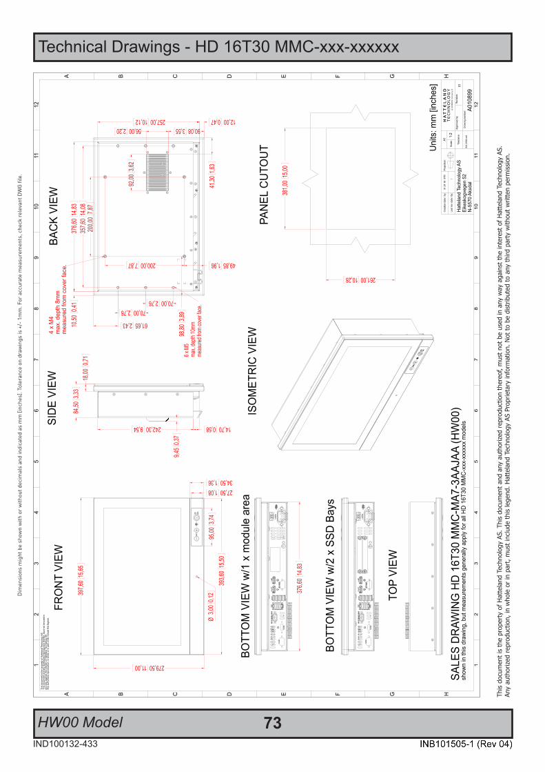
Technical Drawings - HD 16T30 MMC-xxx-xxxxxx
73IND100132-433
This
docu
men
t is
the
prop
erty
of H
atte
land
Tec
hnol
ogy
AS. T
his
docu
men
t and
any
aut
horiz
ed re
prod
uctio
n th
ereo
f, m
ust n
ot b
e us
ed in
any
way
aga
inst
the
inte
rest
of H
atte
land
Tec
hnol
ogy
AS.
Any
auth
orize
d re
prod
uctio
n, in
who
le o
r in
part,
mus
t inc
lude
this
lege
nd. H
atte
land
Tec
hnol
ogy
AS P
ropr
ieta
ry in
form
atio
n. N
ot to
be
dist
ribut
ed to
any
third
par
ty w
ithou
t writ
ten
perm
issio
n.
Dim
ensi
ons
mig
ht b
e sh
own
with
or
with
out d
ecim
als
and
indi
cate
d as
mm
[inc
hes]
. Tol
eran
ce o
n dr
awin
gs is
+/-
1m
m. F
or a
ccur
ate
mea
sure
men
ts, c
heck
rele
vant
DW
G fi
le.
HW00 Model
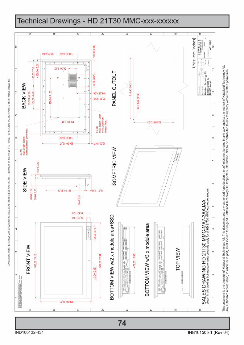
74IND100132-434
This
docu
men
t is
the
prop
erty
of H
atte
land
Tec
hnol
ogy
AS. T
his
docu
men
t and
any
aut
horiz
ed re
prod
uctio
n th
ereo
f, m
ust n
ot b
e us
ed in
any
way
aga
inst
the
inte
rest
of H
atte
land
Tec
hnol
ogy
AS.
Any
auth
orize
d re
prod
uctio
n, in
who
le o
r in
part,
mus
t inc
lude
this
lege
nd. H
atte
land
Tec
hnol
ogy
AS P
ropr
ieta
ry in
form
atio
n. N
ot to
be
dist
ribut
ed to
any
third
par
ty w
ithou
t writ
ten
perm
issio
n.
Dim
ensi
ons
mig
ht b
e sh
own
with
or
with
out d
ecim
als
and
indi
cate
d as
mm
[inc
hes]
. Tol
eran
ce o
n dr
awin
gs is
+/-
1m
m. F
or a
ccur
ate
mea
sure
men
ts, c
heck
rele
vant
DW
G fi
le.
Technical Drawings - HD 21T30 MMC-xxx-xxxxxx
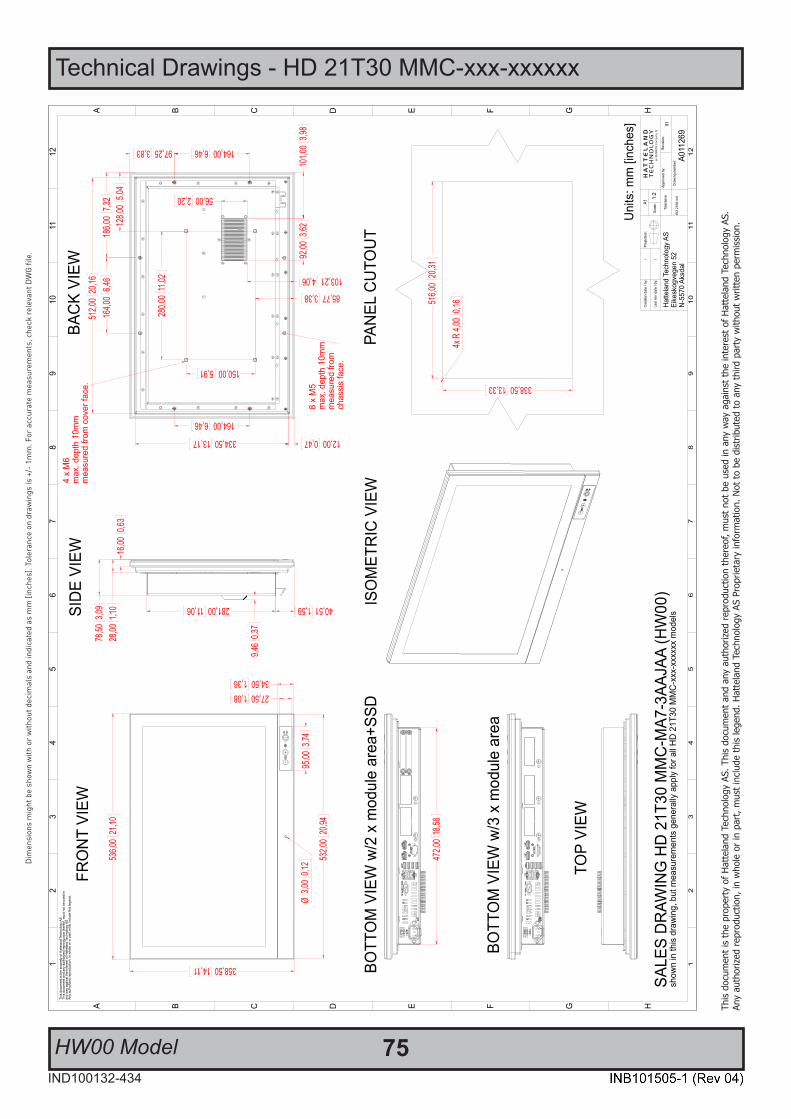
Technical Drawings - HD 21T30 MMC-xxx-xxxxxx
75IND100132-434
This
docu
men
t is
the
prop
erty
of H
atte
land
Tec
hnol
ogy
AS. T
his
docu
men
t and
any
aut
horiz
ed re
prod
uctio
n th
ereo
f, m
ust n
ot b
e us
ed in
any
way
aga
inst
the
inte
rest
of H
atte
land
Tec
hnol
ogy
AS.
Any
auth
orize
d re
prod
uctio
n, in
who
le o
r in
part,
mus
t inc
lude
this
lege
nd. H
atte
land
Tec
hnol
ogy
AS P
ropr
ieta
ry in
form
atio
n. N
ot to
be
dist
ribut
ed to
any
third
par
ty w
ithou
t writ
ten
perm
issio
n.
Dim
ensi
ons
mig
ht b
e sh
own
with
or
with
out d
ecim
als
and
indi
cate
d as
mm
[inc
hes]
. Tol
eran
ce o
n dr
awin
gs is
+/-
1m
m. F
or a
ccur
ate
mea
sure
men
ts, c
heck
rele
vant
DW
G fi
le.
HW00 Model
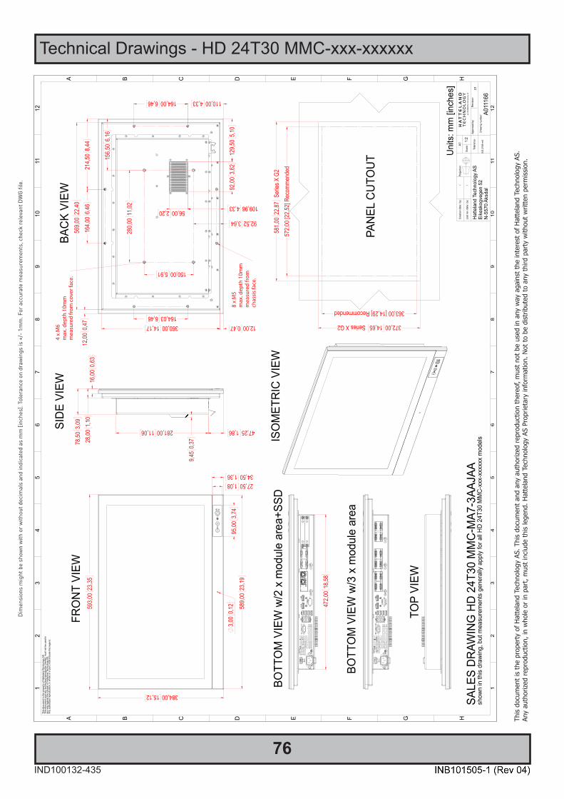
76IND100132-435
This
docu
men
t is
the
prop
erty
of H
atte
land
Tec
hnol
ogy
AS. T
his
docu
men
t and
any
aut
horiz
ed re
prod
uctio
n th
ereo
f, m
ust n
ot b
e us
ed in
any
way
aga
inst
the
inte
rest
of H
atte
land
Tec
hnol
ogy
AS.
Any
auth
orize
d re
prod
uctio
n, in
who
le o
r in
part,
mus
t inc
lude
this
lege
nd. H
atte
land
Tec
hnol
ogy
AS P
ropr
ieta
ry in
form
atio
n. N
ot to
be
dist
ribut
ed to
any
third
par
ty w
ithou
t writ
ten
perm
issio
n.
Dim
ensi
ons
mig
ht b
e sh
own
with
or
with
out d
ecim
als
and
indi
cate
d as
mm
[inc
hes]
. Tol
eran
ce o
n dr
awin
gs is
+/-
1m
m. F
or a
ccur
ate
mea
sure
men
ts, c
heck
rele
vant
DW
G fi
le.
Technical Drawings - HD 24T30 MMC-xxx-xxxxxx

Technical Drawings - HD 24T30 MMC-xxx-xxxxxx
77IND100132-435
This
docu
men
t is
the
prop
erty
of H
atte
land
Tec
hnol
ogy
AS. T
his
docu
men
t and
any
aut
horiz
ed re
prod
uctio
n th
ereo
f, m
ust n
ot b
e us
ed in
any
way
aga
inst
the
inte
rest
of H
atte
land
Tec
hnol
ogy
AS.
Any
auth
orize
d re
prod
uctio
n, in
who
le o
r in
part,
mus
t inc
lude
this
lege
nd. H
atte
land
Tec
hnol
ogy
AS P
ropr
ieta
ry in
form
atio
n. N
ot to
be
dist
ribut
ed to
any
third
par
ty w
ithou
t writ
ten
perm
issio
n.
Dim
ensi
ons
mig
ht b
e sh
own
with
or
with
out d
ecim
als
and
indi
cate
d as
mm
[inc
hes]
. Tol
eran
ce o
n dr
awin
gs is
+/-
1m
m. F
or a
ccur
ate
mea
sure
men
ts, c
heck
rele
vant
DW
G fi
le.
HW00 Model
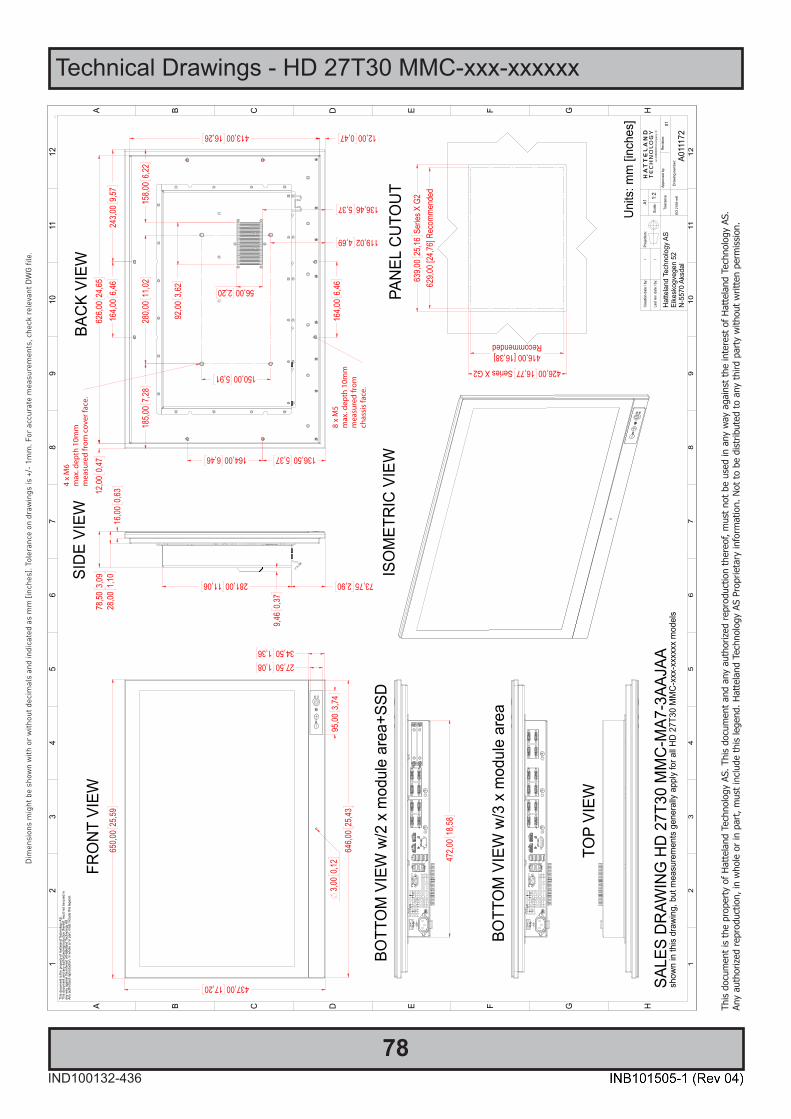
78IND100132-436
This
docu
men
t is
the
prop
erty
of H
atte
land
Tec
hnol
ogy
AS. T
his
docu
men
t and
any
aut
horiz
ed re
prod
uctio
n th
ereo
f, m
ust n
ot b
e us
ed in
any
way
aga
inst
the
inte
rest
of H
atte
land
Tec
hnol
ogy
AS.
Any
auth
orize
d re
prod
uctio
n, in
who
le o
r in
part,
mus
t inc
lude
this
lege
nd. H
atte
land
Tec
hnol
ogy
AS P
ropr
ieta
ry in
form
atio
n. N
ot to
be
dist
ribut
ed to
any
third
par
ty w
ithou
t writ
ten
perm
issio
n.
Dim
ensi
ons
mig
ht b
e sh
own
with
or
with
out d
ecim
als
and
indi
cate
d as
mm
[inc
hes]
. Tol
eran
ce o
n dr
awin
gs is
+/-
1m
m. F
or a
ccur
ate
mea
sure
men
ts, c
heck
rele
vant
DW
G fi
le.
Technical Drawings - HD 27T30 MMC-xxx-xxxxxx
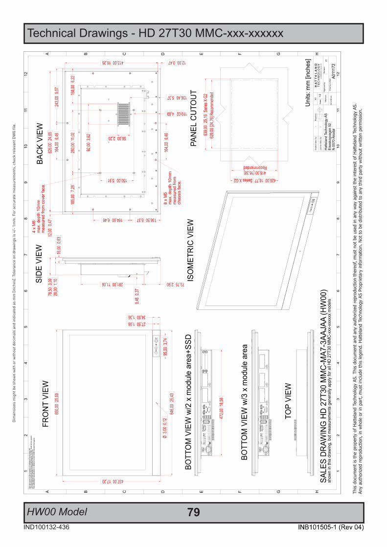
Technical Drawings - HD 27T30 MMC-xxx-xxxxxx
79IND100132-436
This
docu
men
t is
the
prop
erty
of H
atte
land
Tec
hnol
ogy
AS. T
his
docu
men
t and
any
aut
horiz
ed re
prod
uctio
n th
ereo
f, m
ust n
ot b
e us
ed in
any
way
aga
inst
the
inte
rest
of H
atte
land
Tec
hnol
ogy
AS.
Any
auth
orize
d re
prod
uctio
n, in
who
le o
r in
part,
mus
t inc
lude
this
lege
nd. H
atte
land
Tec
hnol
ogy
AS P
ropr
ieta
ry in
form
atio
n. N
ot to
be
dist
ribut
ed to
any
third
par
ty w
ithou
t writ
ten
perm
issio
n.
Dim
ensi
ons
mig
ht b
e sh
own
with
or
with
out d
ecim
als
and
indi
cate
d as
mm
[inc
hes]
. Tol
eran
ce o
n dr
awin
gs is
+/-
1m
m. F
or a
ccur
ate
mea
sure
men
ts, c
heck
rele
vant
DW
G fi
le.
HW00 Model

80
This page left intentionally blank

81
Technical Drawings - Accessories
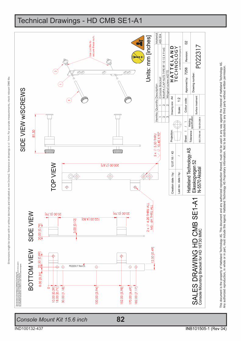
82IND100132-437
This
docu
men
t is
the
prop
erty
of H
atte
land
Tec
hnol
ogy
AS. T
his
docu
men
t and
any
aut
horiz
ed re
prod
uctio
n th
ereo
f, m
ust n
ot b
e us
ed in
any
way
aga
inst
the
inte
rest
of H
atte
land
Tec
hnol
ogy
AS.
Any
auth
orize
d re
prod
uctio
n, in
who
le o
r in
part,
mus
t inc
lude
this
lege
nd. H
atte
land
Tec
hnol
ogy
AS P
ropr
ieta
ry in
form
atio
n. N
ot to
be
dist
ribut
ed to
any
third
par
ty w
ithou
t writ
ten
perm
issio
n.
Dim
ensi
ons
mig
ht b
e sh
own
with
or
with
out d
ecim
als
and
indi
cate
d as
mm
[inc
hes]
. Tol
eran
ce o
n dr
awin
gs is
+/-
1m
m. F
or a
ccur
ate
mea
sure
men
ts, c
heck
rel
evan
t DW
G fi
le.
Technical Drawings - HD CMB SE1-A1
Console Mount Kit 15.6 inch
Hatte
land
Tech
nolog
y AS
Eike
skog
vege
n 52
N-55
70 A
ksda
l
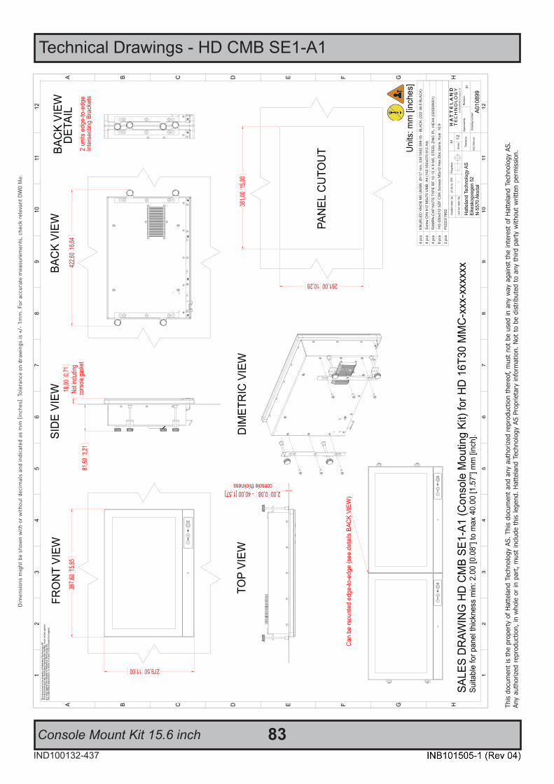
Technical Drawings - HD CMB SE1-A1
Console Mount Kit 15.6 inch 83IND100132-437
This
docu
men
t is
the
prop
erty
of H
atte
land
Tec
hnol
ogy
AS. T
his
docu
men
t and
any
aut
horiz
ed re
prod
uctio
n th
ereo
f, m
ust n
ot b
e us
ed in
any
way
aga
inst
the
inte
rest
of H
atte
land
Tec
hnol
ogy
AS.
Any
auth
orize
d re
prod
uctio
n, in
who
le o
r in
part,
mus
t inc
lude
this
lege
nd. H
atte
land
Tec
hnol
ogy
AS P
ropr
ieta
ry in
form
atio
n. N
ot to
be
dist
ribut
ed to
any
third
par
ty w
ithou
t writ
ten
perm
issio
n.
Dim
ensi
ons
mig
ht b
e sh
own
with
or
with
out d
ecim
als
and
indi
cate
d as
mm
[inc
hes]
. Tol
eran
ce o
n dr
awin
gs is
+/-
1m
m. F
or a
ccur
ate
mea
sure
men
ts, c
heck
rel
evan
t DW
G fi
le.

84IND100132-471
This
docu
men
t is
the
prop
erty
of H
atte
land
Tec
hnol
ogy
AS. T
his
docu
men
t and
any
aut
horiz
ed re
prod
uctio
n th
ereo
f, m
ust n
ot b
e us
ed in
any
way
aga
inst
the
inte
rest
of H
atte
land
Tec
hnol
ogy
AS.
Any
auth
orize
d re
prod
uctio
n, in
who
le o
r in
part,
mus
t inc
lude
this
lege
nd. H
atte
land
Tec
hnol
ogy
AS P
ropr
ieta
ry in
form
atio
n. N
ot to
be
dist
ribut
ed to
any
third
par
ty w
ithou
t writ
ten
perm
issio
n.
Dim
ensi
ons
mig
ht b
e sh
own
with
or
with
out d
ecim
als
and
indi
cate
d as
mm
[inc
hes]
. Tol
eran
ce o
n dr
awin
gs is
+/-
1m
m. F
or a
ccur
ate
mea
sure
men
ts, c
heck
rel
evan
t DW
G fi
le.
Technical Drawings - Console Mount Kit 21.5”, 23.8” & 27.0”
P025485 (“Type A” Bracket)
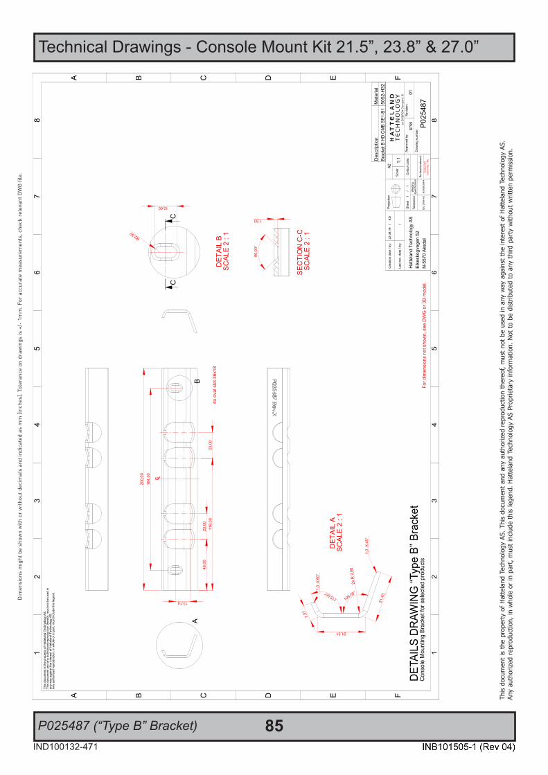
Technical Drawings - Console Mount Kit 21.5”, 23.8” & 27.0”
85IND100132-471
This
docu
men
t is
the
prop
erty
of H
atte
land
Tec
hnol
ogy
AS. T
his
docu
men
t and
any
aut
horiz
ed re
prod
uctio
n th
ereo
f, m
ust n
ot b
e us
ed in
any
way
aga
inst
the
inte
rest
of H
atte
land
Tec
hnol
ogy
AS.
Any
auth
orize
d re
prod
uctio
n, in
who
le o
r in
part,
mus
t inc
lude
this
lege
nd. H
atte
land
Tec
hnol
ogy
AS P
ropr
ieta
ry in
form
atio
n. N
ot to
be
dist
ribut
ed to
any
third
par
ty w
ithou
t writ
ten
perm
issio
n.
Dim
ensi
ons
mig
ht b
e sh
own
with
or
with
out d
ecim
als
and
indi
cate
d as
mm
[inc
hes]
. Tol
eran
ce o
n dr
awin
gs is
+/-
1m
m. F
or a
ccur
ate
mea
sure
men
ts, c
heck
rel
evan
t DW
G fi
le.
P025487 (“Type B” Bracket)
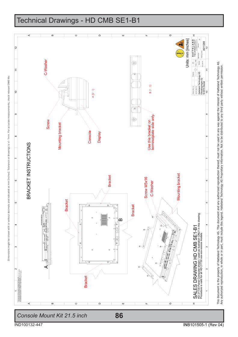
86IND100132-447
This
docu
men
t is
the
prop
erty
of H
atte
land
Tec
hnol
ogy
AS. T
his
docu
men
t and
any
aut
horiz
ed re
prod
uctio
n th
ereo
f, m
ust n
ot b
e us
ed in
any
way
aga
inst
the
inte
rest
of H
atte
land
Tec
hnol
ogy
AS.
Any
auth
orize
d re
prod
uctio
n, in
who
le o
r in
part,
mus
t inc
lude
this
lege
nd. H
atte
land
Tec
hnol
ogy
AS P
ropr
ieta
ry in
form
atio
n. N
ot to
be
dist
ribut
ed to
any
third
par
ty w
ithou
t writ
ten
perm
issio
n.
Dim
ensi
ons
mig
ht b
e sh
own
with
or
with
out d
ecim
als
and
indi
cate
d as
mm
[inc
hes]
. Tol
eran
ce o
n dr
awin
gs is
+/-
1m
m. F
or a
ccur
ate
mea
sure
men
ts, c
heck
rel
evan
t DW
G fi
le.
Technical Drawings - HD CMB SE1-B1
Console Mount Kit 21.5 inch

Technical Drawings - HD CMB SE1-B1
87IND100132-447
This
docu
men
t is
the
prop
erty
of H
atte
land
Tec
hnol
ogy
AS. T
his
docu
men
t and
any
aut
horiz
ed re
prod
uctio
n th
ereo
f, m
ust n
ot b
e us
ed in
any
way
aga
inst
the
inte
rest
of H
atte
land
Tec
hnol
ogy
AS.
Any
auth
orize
d re
prod
uctio
n, in
who
le o
r in
part,
mus
t inc
lude
this
lege
nd. H
atte
land
Tec
hnol
ogy
AS P
ropr
ieta
ry in
form
atio
n. N
ot to
be
dist
ribut
ed to
any
third
par
ty w
ithou
t writ
ten
perm
issio
n.
Dim
ensi
ons
mig
ht b
e sh
own
with
or
with
out d
ecim
als
and
indi
cate
d as
mm
[inc
hes]
. Tol
eran
ce o
n dr
awin
gs is
+/-
1m
m. F
or a
ccur
ate
mea
sure
men
ts, c
heck
rel
evan
t DW
G fi
le.
Console Mounting 21.5 inch

Technical Drawings - HD CMB SE1-B1
88IND100132-447
This
docu
men
t is
the
prop
erty
of H
atte
land
Tec
hnol
ogy
AS. T
his
docu
men
t and
any
aut
horiz
ed re
prod
uctio
n th
ereo
f, m
ust n
ot b
e us
ed in
any
way
aga
inst
the
inte
rest
of H
atte
land
Tec
hnol
ogy
AS.
Any
auth
orize
d re
prod
uctio
n, in
who
le o
r in
part,
mus
t inc
lude
this
lege
nd. H
atte
land
Tec
hnol
ogy
AS P
ropr
ieta
ry in
form
atio
n. N
ot to
be
dist
ribut
ed to
any
third
par
ty w
ithou
t writ
ten
perm
issio
n.
Dim
ensi
ons
mig
ht b
e sh
own
with
or
with
out d
ecim
als
and
indi
cate
d as
mm
[inc
hes]
. Tol
eran
ce o
n dr
awin
gs is
+/-
1m
m. F
or a
ccur
ate
mea
sure
men
ts, c
heck
rel
evan
t DW
G fi
le.
Flush Mounting 21.5 inch
537,0
021
,1451
6,00
20,31
10,50
0,41
338,5013,33359,5014,15
10,500,41
AA
Cons
ole th
ickne
ss
220,008,66
16,00
0,63
2x R
4,00
0,16
16,00
0,63
Sun
ken f
ace f
or D
isplay
10,00
0,39
Max
thick
ness
for m
ounti
ng th
e bra
cket
Cons
ole th
ickne
ss
A-A
(2 :
1)
FRO
NT
VIEW
SID
E VI
EWBA
CK
VIEW
FLU
SH M
OU
NTI
NG
DET
AILS
- PA
NEL
CU
TOU
TAp
plie
s fo
r all
21 in
ch D
ispl
ays
and
Pane
l Com
pute
rs
H
12
GFE
34
56
DCBA
12
34
56
78
78
GFE
910
DCB
1112
A
910
1112
H
Hat
tela
nd T
echn
olog
y AS
Eike
skog
vege
n 52
N-5
570
Aksd
alP0
2546
7
Proj
ectio
n:
This
doc
umen
t is
the
prop
erty
of H
atte
land
Tec
hnol
ogy
AS.
This
doc
umen
t and
any
aut
horiz
ed re
prod
uctio
n th
ereo
f, m
ust n
ot b
e us
ed in
any
way
aga
inst
the
inte
rest
of H
atte
land
Tec
hnol
ogy
AS.
Any
auth
oriz
ed re
prod
uctio
n, in
who
le o
r in
part,
mus
t inc
lude
this
lege
nd.
01
Rev
isio
n:Ap
prov
ed b
y:
Dra
win
g nu
mbe
r:
A1
1:3
Scal
e:La
st re
v. d
ate
/ by:
/
Cre
atio
n da
te /
by:
/KD
16.0
8.19
ISO
276
8-m
K
Tole
ranc
e
Uni
ts: m
m [i
nche
s]
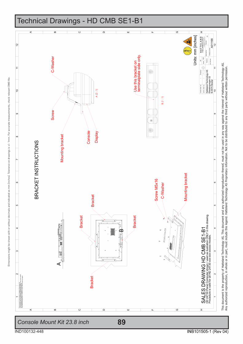
89IND100132-448
This
docu
men
t is
the
prop
erty
of H
atte
land
Tec
hnol
ogy
AS. T
his
docu
men
t and
any
aut
horiz
ed re
prod
uctio
n th
ereo
f, m
ust n
ot b
e us
ed in
any
way
aga
inst
the
inte
rest
of H
atte
land
Tec
hnol
ogy
AS.
Any
auth
orize
d re
prod
uctio
n, in
who
le o
r in
part,
mus
t inc
lude
this
lege
nd. H
atte
land
Tec
hnol
ogy
AS P
ropr
ieta
ry in
form
atio
n. N
ot to
be
dist
ribut
ed to
any
third
par
ty w
ithou
t writ
ten
perm
issio
n.
Dim
ensi
ons
mig
ht b
e sh
own
with
or
with
out d
ecim
als
and
indi
cate
d as
mm
[inc
hes]
. Tol
eran
ce o
n dr
awin
gs is
+/-
1m
m. F
or a
ccur
ate
mea
sure
men
ts, c
heck
rel
evan
t DW
G fi
le.
Technical Drawings - HD CMB SE1-B1
Console Mount Kit 23.8 inch

Technical Drawings - HD CMB SE1-B1
90IND100132-448
This
docu
men
t is
the
prop
erty
of H
atte
land
Tec
hnol
ogy
AS. T
his
docu
men
t and
any
aut
horiz
ed re
prod
uctio
n th
ereo
f, m
ust n
ot b
e us
ed in
any
way
aga
inst
the
inte
rest
of H
atte
land
Tec
hnol
ogy
AS.
Any
auth
orize
d re
prod
uctio
n, in
who
le o
r in
part,
mus
t inc
lude
this
lege
nd. H
atte
land
Tec
hnol
ogy
AS P
ropr
ieta
ry in
form
atio
n. N
ot to
be
dist
ribut
ed to
any
third
par
ty w
ithou
t writ
ten
perm
issio
n.
Dim
ensi
ons
mig
ht b
e sh
own
with
or
with
out d
ecim
als
and
indi
cate
d as
mm
[inc
hes]
. Tol
eran
ce o
n dr
awin
gs is
+/-
1m
m. F
or a
ccur
ate
mea
sure
men
ts, c
heck
rel
evan
t DW
G fi
le.
Console Mounting 23.8 inch

Technical Drawings - HD CMB SE1-B1
91IND100132-448
This
docu
men
t is
the
prop
erty
of H
atte
land
Tec
hnol
ogy
AS. T
his
docu
men
t and
any
aut
horiz
ed re
prod
uctio
n th
ereo
f, m
ust n
ot b
e us
ed in
any
way
aga
inst
the
inte
rest
of H
atte
land
Tec
hnol
ogy
AS.
Any
auth
orize
d re
prod
uctio
n, in
who
le o
r in
part,
mus
t inc
lude
this
lege
nd. H
atte
land
Tec
hnol
ogy
AS P
ropr
ieta
ry in
form
atio
n. N
ot to
be
dist
ribut
ed to
any
third
par
ty w
ithou
t writ
ten
perm
issio
n.
Dim
ensi
ons
mig
ht b
e sh
own
with
or
with
out d
ecim
als
and
indi
cate
d as
mm
[inc
hes]
. Tol
eran
ce o
n dr
awin
gs is
+/-
1m
m. F
or a
ccur
ate
mea
sure
men
ts, c
heck
rel
evan
t DW
G fi
le.
Flush Mounting 23.8 inch
572,0
022
,5259
4,00
23,39
363,0014,29385,0015,16
11,000,43
11,00
0,43
4x R
2,00
0,08
4x R
4,00
0,16
AA
Cons
ole th
ickne
ss
16,00
0,63
2x R
4,00
0,16
220,008,66
16,00
0,63
Sun
ker f
ace f
or D
isplay
10,00
0,39
Max
thick
ness
for m
ounti
ng th
e bra
cket
Cons
ole th
ickne
ss
A-A
(2 :
1)
FRO
NT
VIEW
SID
E VI
EWBA
CK
VIEW
FLU
SH M
OU
NTI
NG
DET
AILS
- PA
NEL
CU
TOU
TAp
plie
s fo
r all
24 in
ch D
ispl
ays
and
Pane
l Com
pute
rs
H
12
GFE
34
56
DCBA
12
34
56
78
78
GFE
910
DCB
1112
A
910
1112
H
Hat
tela
nd T
echn
olog
y AS
Eike
skog
vege
n 52
N-5
570
Aksd
alP0
2547
1
Proj
ectio
n:
This
doc
umen
t is
the
prop
erty
of H
atte
land
Tec
hnol
ogy
AS.
This
doc
umen
t and
any
aut
horiz
ed re
prod
uctio
n th
ereo
f, m
ust n
ot b
e us
ed in
any
way
aga
inst
the
inte
rest
of H
atte
land
Tec
hnol
ogy
AS.
Any
auth
oriz
ed re
prod
uctio
n, in
who
le o
r in
part,
mus
t inc
lude
this
lege
nd.
01
Rev
isio
n:Ap
prov
ed b
y:
Dra
win
g nu
mbe
r:
A1
1:3
Scal
e:La
st re
v. d
ate
/ by:
/
Cre
atio
n da
te /
by:
/KD
19.0
8.19
ISO
276
8-m
K
Tole
ranc
e
Uni
ts: m
m [i
nche
s]

92IND100132-449
This
docu
men
t is
the
prop
erty
of H
atte
land
Tec
hnol
ogy
AS. T
his
docu
men
t and
any
aut
horiz
ed re
prod
uctio
n th
ereo
f, m
ust n
ot b
e us
ed in
any
way
aga
inst
the
inte
rest
of H
atte
land
Tec
hnol
ogy
AS.
Any
auth
orize
d re
prod
uctio
n, in
who
le o
r in
part,
mus
t inc
lude
this
lege
nd. H
atte
land
Tec
hnol
ogy
AS P
ropr
ieta
ry in
form
atio
n. N
ot to
be
dist
ribut
ed to
any
third
par
ty w
ithou
t writ
ten
perm
issio
n.
Dim
ensi
ons
mig
ht b
e sh
own
with
or
with
out d
ecim
als
and
indi
cate
d as
mm
[inc
hes]
. Tol
eran
ce o
n dr
awin
gs is
+/-
1m
m. F
or a
ccur
ate
mea
sure
men
ts, c
heck
rel
evan
t DW
G fi
le.
Technical Drawings - HD CMB SE1-B1
Flush Mounting 27.0 inch
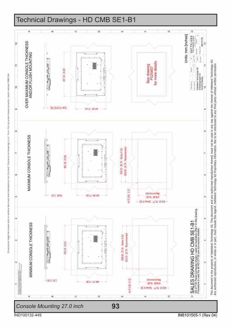
Technical Drawings - HD CMB SE1-B1
93IND100132-449
This
docu
men
t is
the
prop
erty
of H
atte
land
Tec
hnol
ogy
AS. T
his
docu
men
t and
any
aut
horiz
ed re
prod
uctio
n th
ereo
f, m
ust n
ot b
e us
ed in
any
way
aga
inst
the
inte
rest
of H
atte
land
Tec
hnol
ogy
AS.
Any
auth
orize
d re
prod
uctio
n, in
who
le o
r in
part,
mus
t inc
lude
this
lege
nd. H
atte
land
Tec
hnol
ogy
AS P
ropr
ieta
ry in
form
atio
n. N
ot to
be
dist
ribut
ed to
any
third
par
ty w
ithou
t writ
ten
perm
issio
n.
Dim
ensi
ons
mig
ht b
e sh
own
with
or
with
out d
ecim
als
and
indi
cate
d as
mm
[inc
hes]
. Tol
eran
ce o
n dr
awin
gs is
+/-
1m
m. F
or a
ccur
ate
mea
sure
men
ts, c
heck
rel
evan
t DW
G fi
le.
Console Mounting 27.0 inch
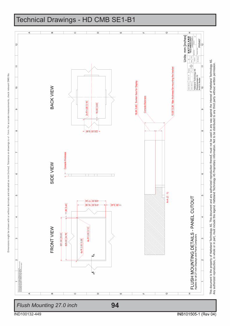
Technical Drawings - HD CMB SE1-B1
94IND100132-449
This
docu
men
t is
the
prop
erty
of H
atte
land
Tec
hnol
ogy
AS. T
his
docu
men
t and
any
aut
horiz
ed re
prod
uctio
n th
ereo
f, m
ust n
ot b
e us
ed in
any
way
aga
inst
the
inte
rest
of H
atte
land
Tec
hnol
ogy
AS.
Any
auth
orize
d re
prod
uctio
n, in
who
le o
r in
part,
mus
t inc
lude
this
lege
nd. H
atte
land
Tec
hnol
ogy
AS P
ropr
ieta
ry in
form
atio
n. N
ot to
be
dist
ribut
ed to
any
third
par
ty w
ithou
t writ
ten
perm
issio
n.
Dim
ensi
ons
mig
ht b
e sh
own
with
or
with
out d
ecim
als
and
indi
cate
d as
mm
[inc
hes]
. Tol
eran
ce o
n dr
awin
gs is
+/-
1m
m. F
or a
ccur
ate
mea
sure
men
ts, c
heck
rel
evan
t DW
G fi
le.
Flush Mounting 27.0 inch
651,0
025
,63
629,0
024
,7611
,000,4
3
4x R
2,00
0,08 4x R
3,00
0,12
416,0016,38438,0017,24
11,000,43
AA
Cons
ole th
ickne
ss
220,008,66
16,00
0,63
2x R
4,00
0,16
10,00
0,39
Max
thick
ness
for m
ounti
ng th
e bra
cket
16,00
0,63
Sun
ken f
ace f
or D
isplay
Cons
ole th
ickne
ss
A-A
(2 :
1)
BAC
K VI
EWSI
DE
VIEW
FRO
NT
VIEW
FLU
SH M
OU
NTI
NG
DET
AILS
- PA
NEL
CU
TOU
TAp
plie
s fo
r all
27 in
ch D
ispl
ays
and
Pane
l Com
pute
rs
H
12
GFE
34
56
DCBA
12
34
56
78
78
GFE
910
DCB
1112
A
910
1112
H
Hat
tela
nd T
echn
olog
y AS
Eike
skog
vege
n 52
N-5
570
Aksd
alP0
2545
7
Proj
ectio
n:
This
doc
umen
t is
the
prop
erty
of H
atte
land
Tec
hnol
ogy
AS.
This
doc
umen
t and
any
aut
horiz
ed re
prod
uctio
n th
ereo
f, m
ust n
ot b
e us
ed in
any
way
aga
inst
the
inte
rest
of H
atte
land
Tec
hnol
ogy
AS.
Any
auth
oriz
ed re
prod
uctio
n, in
who
le o
r in
part,
mus
t inc
lude
this
lege
nd.
01
Rev
isio
n:Ap
prov
ed b
y:
Dra
win
g nu
mbe
r:
A1
1:3
Scal
e:La
st re
v. d
ate
/ by:
/
Cre
atio
n da
te /
by:
/KD
14.0
8.19
ISO
276
8-m
K
Tole
ranc
e
Uni
ts: m
m [i
nche
s]
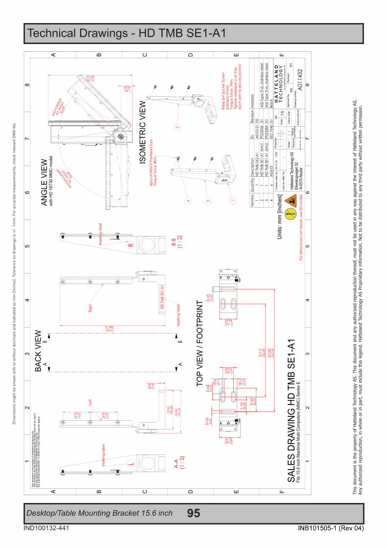
95IND100132-441
This
docu
men
t is
the
prop
erty
of H
atte
land
Tec
hnol
ogy
AS. T
his
docu
men
t and
any
aut
horiz
ed re
prod
uctio
n th
ereo
f, m
ust n
ot b
e us
ed in
any
way
aga
inst
the
inte
rest
of H
atte
land
Tec
hnol
ogy
AS.
Any
auth
orize
d re
prod
uctio
n, in
who
le o
r in
part,
mus
t inc
lude
this
lege
nd. H
atte
land
Tec
hnol
ogy
AS P
ropr
ieta
ry in
form
atio
n. N
ot to
be
dist
ribut
ed to
any
third
par
ty w
ithou
t writ
ten
perm
issio
n.
Dim
ensi
ons
mig
ht b
e sh
own
with
or
with
out d
ecim
als
and
indi
cate
d as
mm
[inc
hes]
. Tol
eran
ce o
n dr
awin
gs is
+/-
1m
m. F
or a
ccur
ate
mea
sure
men
ts, c
heck
rel
evan
t DW
G fi
le.
Technical Drawings - HD TMB SE1-A1
Desktop/Table Mounting Bracket 15.6 inch
Hatte
land T
echn
ology
AS
Eike
skog
vege
n 52
N-55
70 A
ksda
l
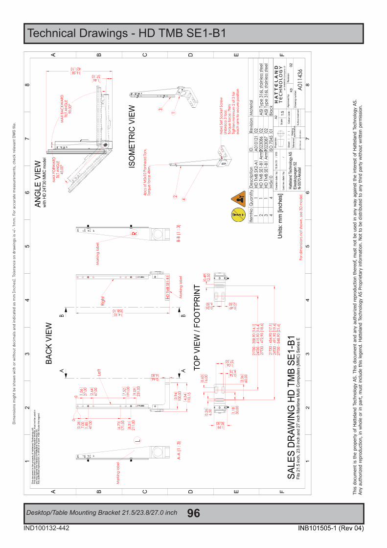
96IND100132-442
This
docu
men
t is
the
prop
erty
of H
atte
land
Tec
hnol
ogy
AS. T
his
docu
men
t and
any
aut
horiz
ed re
prod
uctio
n th
ereo
f, m
ust n
ot b
e us
ed in
any
way
aga
inst
the
inte
rest
of H
atte
land
Tec
hnol
ogy
AS.
Any
auth
orize
d re
prod
uctio
n, in
who
le o
r in
part,
mus
t inc
lude
this
lege
nd. H
atte
land
Tec
hnol
ogy
AS P
ropr
ieta
ry in
form
atio
n. N
ot to
be
dist
ribut
ed to
any
third
par
ty w
ithou
t writ
ten
perm
issio
n.
Dim
ensi
ons
mig
ht b
e sh
own
with
or
with
out d
ecim
als
and
indi
cate
d as
mm
[inc
hes]
. Tol
eran
ce o
n dr
awin
gs is
+/-
1m
m. F
or a
ccur
ate
mea
sure
men
ts, c
heck
rel
evan
t DW
G fi
le.
Technical Drawings - HD TMB SE1-B1
Desktop/Table Mounting Bracket 21.5/23.8/27.0 inch
Hatte
land T
echn
ology
AS
Eike
skog
vege
n 52
N-55
70 A
ksda
l

97IND100132-245
This
docu
men
t is
the
prop
erty
of H
atte
land
Tec
hnol
ogy
AS. T
his
docu
men
t and
any
aut
horiz
ed re
prod
uctio
n th
ereo
f, m
ust n
ot b
e us
ed in
any
way
aga
inst
the
inte
rest
of H
atte
land
Tec
hnol
ogy
AS.
Any
auth
orize
d re
prod
uctio
n, in
who
le o
r in
part,
mus
t inc
lude
this
lege
nd. H
atte
land
Tec
hnol
ogy
AS P
ropr
ieta
ry in
form
atio
n. N
ot to
be
dist
ribut
ed to
any
third
par
ty w
ithou
t writ
ten
perm
issio
n.
Dim
ensi
ons
mig
ht b
e sh
own
with
or
with
out d
ecim
als
and
indi
cate
d as
mm
[inc
hes]
. Tol
eran
ce o
n dr
awin
gs is
+/-
1m
m. F
or a
ccur
ate
mea
sure
men
ts, c
heck
rel
evan
t DW
G fi
le.
Hatte
land
Tec
hnol
ogy A
SEi
kesk
ogve
gen
52N-
5570
Aks
dal
Technical Drawings - External Modules (USB)

98
This page left intentionally blank

99
Appendixes

100AppendixIND100077-206
IoT Enabled Products from Hatteland Technology
Sensors
Disk HealthDisk Space
System HeatFans
TemperaturesVoltageTimers
Light SensorsBacklight Setting
SYSTEM PROCESSING PRESENTATION
• Alarm• MRP Integration• System Surveillance• Device Status
IoT HUB Cloud Service
IoT EDGE
With IoT you can easy, fast and secure review any product parameters, Accessible from anywhere on any device, Monitor and estimate health of products to ensure optimal operation today and tomorrow, Keep track of events down to seconds or past years to plan future maintainance and more. Via an IoT EDGE application you can collect data from the various sensors in our products, and send this information to a Cloud Service for further processing and analytics.
The table below provides an overview of onboard IoT parameters of the units and their access methods. The system built around are equipped with features of sensoring temperature, voltage, environmental luminance and otherdiagnostic parameters. The end-user can utilize the parameters to analyze the working status of the system. The IoT parameters are distributed in different modules, examples SuperIO, VCOM and S.M.A.R.T.
Since the data sent to Cloud Service is stored in a structured plain text format and accessible via standarized API, there is no limits on how you can use this data further in any type of application, part of software development or even design your own customized graphical layouts to easily illustrate the data - in near real-time!
Access to parameters - Series E Panel Computers (MMC)
IoT (Internet of Things) Overview
Typenumbers Chipset IoT Parameter Hardware Access Method Reference
HD 16T30 MMCHD 21T30 MMCHD 24T30 MMCHD 27T30 MMC
Intel® SOC
VBAT (CMOS Battery Voltage) Motherboard
SCOM "SIO"www.hattelandtechnology.com/hubfs/pdfget/inb100018-7.htm
VCore (CPU Core Voltage) MotherboardV5V (+5V) MotherboardV12V (+12V) MotherboardV3VSB (3.3V Standby) MotherboardV3VCC (3.3V Active) MotherboardCPUTEMP (CPU temperature PECI) MotherboardSYSTEMP (SYS Temperature onboard) MotherboardCPUFAN (CPU FAN speed) FANLIS (Light Sensor via SCOM) Light Sensor SCOM "LIS"S.M.A.R.T. Data HDD/SSD S.M.A.R.T Monitor Tools www.smartmontools.orgSystem Parameters provided byOperating System, like CPU load, RAM load, Disk load etc
Motherboard WinAPI Example: OpenHardwareMonitorwww.github.com/openhardwaremonitor/openhardwaremonitor
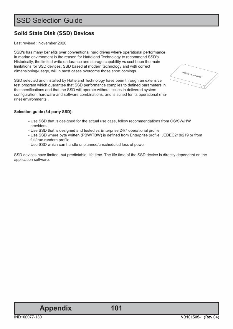
101AppendixIND100077-130
SSD Selection Guide
Solid State Disk (SSD) DevicesLast revised : November 2020
SSD's has many benefits over conventional hard drives where operational performance in marine environment is the reason for Hatteland Technology to recommend SSD's. Historically, the limited write endurance and storage capability vs cost been the mainlimitations for SSD devices. SSD based at modern technology and with correctdimensioning/usage, will in most cases overcome those short comings.
SSD selected and installed by Hatteland Technology have been through an extensive test program which guarantee that SSD performance complies to defined parameters in the specifications and that the SSD will operate without issues in delivered systemconfiguration, hardware and software combinations, and is suited for its operational (ma-rine) environments .
Selection guide (3d-party SSD): - Use SSD that is designed for the actual use case, follow recommendations from OS/SW/HW providers. - Use SSD that is designed and tested vs Enterprise 24/7 operational profile. - Use SSD where byte written (PBW/TBW) is defined from Enterprise profile; JEDEC218/219 or from full/true random profile. - Use SSD which can handle unplanned/unscheduled loss of power SSD devices have limited, but predictable, life time. The life time of the SSD device is directly dependent on theapplication software.
102
SSD Selection Guide
AppendixIND100077-130
Calculation / estimation of operational lifetimeAssumed System with Hatteland Technology provided SSD or selected according to guide above.
1. Measure/estimate/calculate average disk usage per day. For measuring, use SMART data. o Measure the difference in numbers of write cycles at the start and at end of the test (or the difference in remaining lifetime) o Run the test with relevant disk load and during relevant time period Relevant disk load - should correspond to the average disk load during the operational lifetime. Relevant time - time it takes to generate relevant disk load with statically significance. Many SSD manufacturers provide tool for calculating expected operational lifetime.
2. Selection of SSD
Select SSD type/series. Define minimum expected lifetime [Year] Define minimum required SSD capacity [GB]
From datasheet, - check if the endurance is expressed as PBW/TBW or DWPD. - check warranty [year]
PBW - PetaByte Written = 1000 terabyte written = 1000 000 gigabyte written. TBW - Total Byte Written normally expressed in terabyte. DWPD - Disk Write Per Day.
Note relation TBW and DWPD : TBW = DPWD * warranty * 365 * SSD capacity.
Calculate minimum TBW/DPWD. If TBW in datasheet : TBW = Lifetime *365 * average disk load per day. If DPWD in datasheet : DPWD = TBW / (warranty * 365 * SSD capacity).
Use datasheet, Select disk where actual capacity is greater or equal to minimum required capacity and TBW/DPWP in datasheet is greater or equal to calculated minimum TBW/DPWD.
If lifetime is not according to requirements: Select different SSD, size and/or type, or use mechanism such as over provisioning to extend the operational lifetime.

103
SSD Selection Guide
AppendixIND100077-130
Calculation of required size of SSD (Multi-Level Cell - MLC) device The table below details the write endurance of the an enterprise environment. All values are verified by HattelandTechnology during the qualification / selection process. Please review our relevant Product Datasheets for your unit to determine the actual installed device and its TBW values before proceeding with calculations below.
Write Endurance Specifications Previous 2.5” SSD (MLC)
Write Endurance Specifications Current 2.5” SSD (MLC)
Device Size Value in TBW (Terabytes) Device Size Value in TBW (Terabytes)80 GB 45 150 GB 412
120 GB 70 240 GB 599160 GB 100 480 GB 945240 GB 140 800 GB 1663300 GB 225 960 GB 1750600 GB 330 1200 GB 2455
JESD218 standard1 and based on JESD219 workload.
Formula for calculating disk size:z = y * x
Where y = Requested minimum lifetime (with respect to wear out, [year]).Where x = Data rate (GB /per year).Where z = Total amount of data written data to SSD during its whole lifetime.
Step-by-Step Calculation Step 1: Measure (preferred) or estimate data rate y, [GB /per year].Step 2: Define minimum expected lifetime for SSD device x [year].Step 3: Calculate total amount of data written to the SSD during its whole lifetime, z = y * x.Step 4: Use table, column 2, the z value shall be less or equal to the value in the table to achieve requested lifetime.
Write Endurance Specifications Previous 2.5” SSD (MLC)
Write Endurance Specifications Current 2.5” SSD (MLC)
Device Size Value in TBW (Terabytes) Device Size Value in TBW (Terabytes)80 GB 45 150 GB 412
120 GB 70 240 GB 599160 GB 100 480 GB 945240 GB 140 800 GB 1663300 GB 225 960 GB 1750600 GB 330 1200 GB 2455
Step 5: Select the SSD device, column 1, which corresponds to the selected value in column 2.Step 6. Check that the size of the selected SSD is greater than required size of the SSD, if not select the size of the SSD that matches customer requirements.
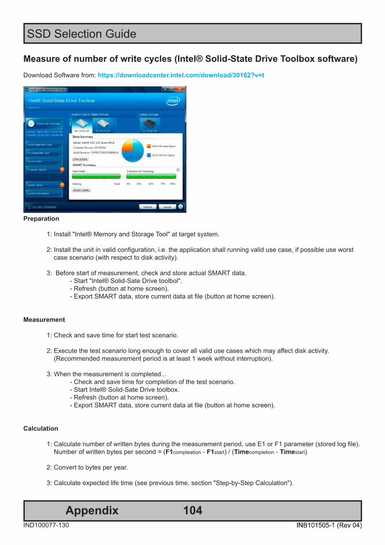
104
SSD Selection Guide
AppendixIND100077-130
Measure of number of write cycles (Intel® Solid-State Drive Toolbox software)Download Software from: https://downloadcenter.intel.com/download/30162?v=t
Preparation
1: Install "Intel® Memory and Storage Tool" at target system.
2: Install the unit in valid configuration, i.e. the application shall running valid use case, if possible use worst case scenario (with respect to disk activity).
3: Before start of measurement, check and store actual SMART data. - Start "Intel® Solid-Sate Drive toolbol". - Refresh (button at home screen). - Export SMART data, store current data at file (button at home screen).
Measurement
1: Check and save time for start test scenario.
2: Execute the test scenario long enough to cover all valid use cases which may affect disk activity. (Recommended measurement period is at least 1 week without interruption).
3: When the measurement is completed... - Check and save time for completion of the test scenario. - Start Intel® Solid-Sate Drive toolbox. - Refresh (button at home screen). - Export SMART data, store current data at file (button at home screen).
Calculation
1: Calculate number of written bytes during the measurement period, use E1 or F1 parameter (stored log file). Number of written bytes per second = (F1compleation - F1start) / (Timecompletion - Timestart)
2: Convert to bytes per year.
3: Calculate expected life time (see previous time, section "Step-by-Step Calculation").
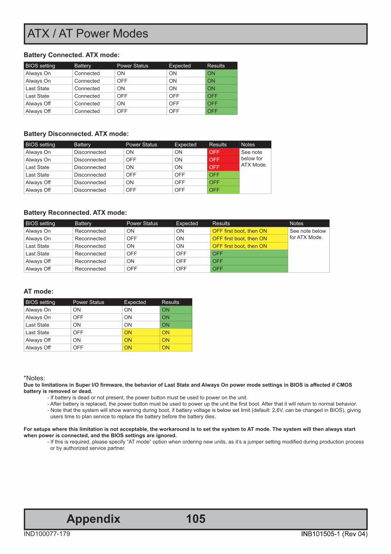
105AppendixIND100077-179
ATX / AT Power ModesBattery Connected. ATX mode:BIOS setting Battery Power Status Expected ResultsAlways On Connected ON ON ONAlways On Connected OFF ON ONLast State Connected ON ON ONLast State Connected OFF OFF OFFAlways Off Connected ON OFF OFFAlways Off Connected OFF OFF OFF
Battery Disconnected. ATX mode:BIOS setting Battery Power Status Expected Results NotesAlways On Disconnected ON ON OFF See note
below for ATX Mode.
Always On Disconnected OFF ON OFFLast State Disconnected ON ON OFFLast State Disconnected OFF OFF OFFAlways Off Disconnected ON OFF OFFAlways Off Disconnected OFF OFF OFF
Battery Reconnected. ATX mode:BIOS setting Battery Power Status Expected Results NotesAlways On Reconnected ON ON OFF first boot, then ON See note below
for ATX Mode.Always On Reconnected OFF ON OFF first boot, then ONLast State Reconnected ON ON OFF first boot, then ONLast State Reconnected OFF OFF OFFAlways Off Reconnected ON OFF OFFAlways Off Reconnected OFF OFF OFF
AT mode:BIOS setting Power Status Expected ResultsAlways On ON ON ONAlways On OFF ON ONLast State ON ON ONLast State OFF ON ONAlways Off ON ON ONAlways Off OFF ON ON
*Notes:Due to limitations in Super I/O firmware, the behavior of Last State and Always On power mode settings in BIOS is affected if CMOS battery is removed or dead. - If battery is dead or not present, the power button must be used to power on the unit. - After battery is replaced, the power button must be used to power up the unit the first boot. After that it will return to normal behavior. - Note that the system will show warning during boot, if battery voltage is below set limit (default: 2,6V, can be changed in BIOS), giving users time to plan service to replace the battery before the battery dies.
For setups where this limitation is not acceptable, the workaround is to set the system to AT mode. The system will then always start when power is connected, and the BIOS settings are ignored. - If this is required, please specify “AT mode” option when ordering new units, as it’s a jumper setting modified during production process or by authorized service partner.
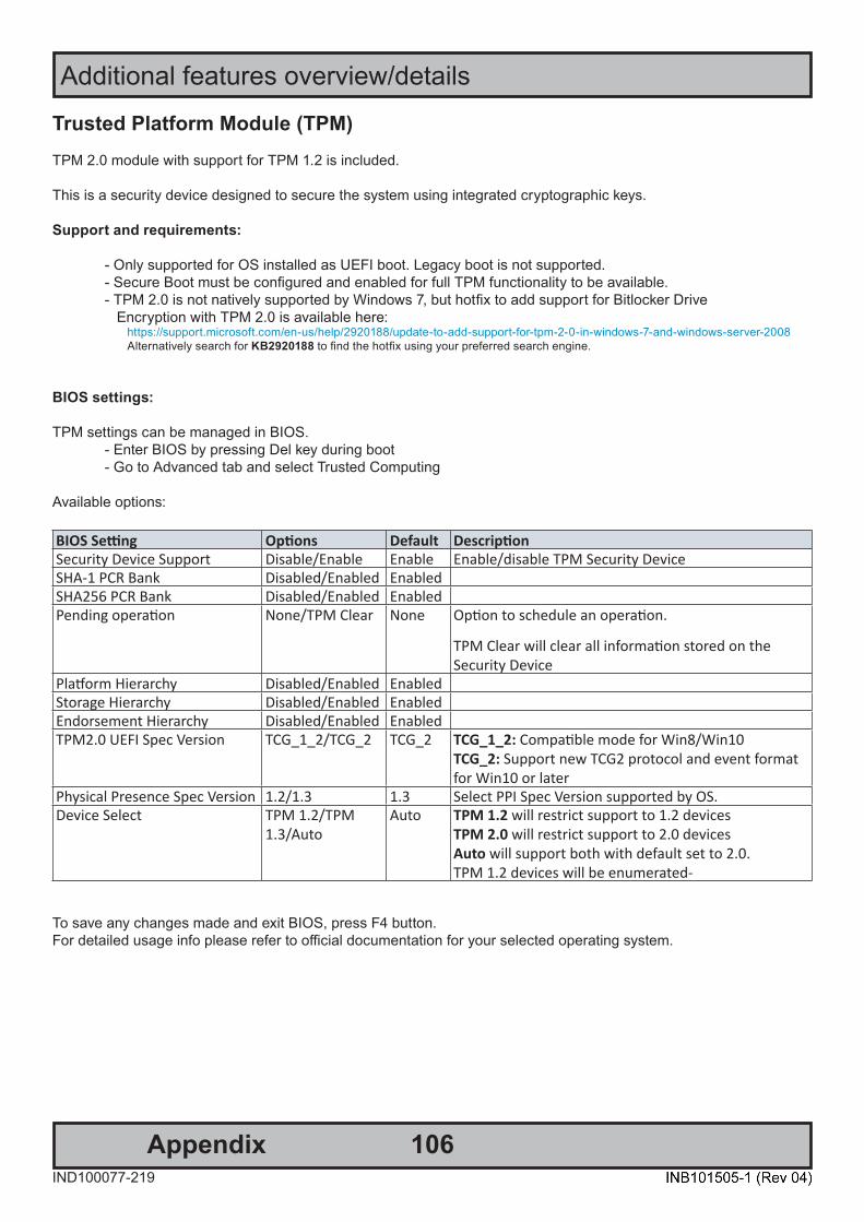
106AppendixIND100077-219
Additional features overview/details
Trusted Platform Module (TPM) TPM 2.0 module with support for TPM 1.2 is included.
This is a security device designed to secure the system using integrated cryptographic keys.
Support and requirements:
- Only supported for OS installed as UEFI boot. Legacy boot is not supported. - Secure Boot must be configured and enabled for full TPM functionality to be available. - TPM 2.0 is not natively supported by Windows 7, but hotfix to add support for Bitlocker Drive Encryption with TPM 2.0 is available here: https://support.microsoft.com/en-us/help/2920188/update-to-add-support-for-tpm-2-0-in-windows-7-and-windows-server-2008 Alternatively search for KB2920188 to find the hotfix using your preferred search engine.
BIOS settings:
TPM settings can be managed in BIOS. - Enter BIOS by pressing Del key during boot - Go to Advanced tab and select Trusted Computing
Available options:
BIOS Setting Options Default DescriptionSecurity Device Support Disable/Enable Enable Enable/disable TPM Security DeviceSHA-1 PCR Bank Disabled/Enabled EnabledSHA256 PCR Bank Disabled/Enabled EnabledPending operation None/TPM Clear None Option to schedule an operation.
TPM Clear will clear all information stored on the Security Device
Platform Hierarchy Disabled/Enabled EnabledStorage Hierarchy Disabled/Enabled EnabledEndorsement Hierarchy Disabled/Enabled EnabledTPM2.0 UEFI Spec Version TCG_1_2/TCG_2 TCG_2 TCG_1_2: Compatible mode for Win8/Win10
TCG_2: Support new TCG2 protocol and event format for Win10 or later
Physical Presence Spec Version 1.2/1.3 1.3 Select PPI Spec Version supported by OS.Device Select TPM 1.2/TPM
1.3/AutoAuto TPM 1.2 will restrict support to 1.2 devices
TPM 2.0 will restrict support to 2.0 devices Auto will support both with default set to 2.0. TPM 1.2 devices will be enumerated-
To save any changes made and exit BIOS, press F4 button.For detailed usage info please refer to official documentation for your selected operating system.

107
Additional features overview/details
AppendixIND100077-219
Secure Boot Secure Boot is a security feature that can protect the system from running unauthorized boot loaders and avoidloading non-signed drivers during boot process. The feature is only supported for boot devices in UEFI mode.
CSM Support (BIOS Legacy boot and Option ROM support) is not compatible with this security feature and must be disabled in BIOS before enabling Secure Boot.
Basic Procedure:
-Set UEFI boot type in BIOS (set by default) - Enter BIOS by pressing Del key during boot. - Navigate to Boot tab in BIOS - Make sure Boot mode select is set to: UEFI Boot Type - Press F4 to save and Exit
- Disable CSM Support - Enter BIOS by pressing Del key during boot. - Go to Advanced tab and Select “CSM Configuration”. - Set CSM Support to Disabled - Press F4 to save and exit (unit must be restarted before continuing)
- Enable Secure Boot - Enter BIOS by pressing Del key during boot. - Go to Security tab and Select “Secure Boot”. - Set Attempt Secure Boot to Enabled - Secure Boot Mode is set to standard as default. - Customized option will enable Key Management menu below with advanced settings. - Press F4 to save and exit
Choose Boot Device By factory default, press F7 to choose boot device at startup of unit.

108
Additional features overview/details
AppendixIND100077-219
Battery Status and Alarm CMOS battery voltage is monitored during each boot and the following warning will show if it’s below set low limit:
WARNING!!! The CMOS battery capacity too low.
If this error is displayed, it is recommended to schedule service of the unit for replacement of CMOS battery.
When the CMOS battery is dead, or voltage is too low, it will not keep track of time/date when power is disconnected. BIOS settings will still be remembered, but bootup takes longer time and some BIOS related functions may not work optimally without battery.
The low limit is set to 2.4V by default. This is the minimum voltage required by main board for full functionality and to keep track of time and date while powered off.
The low voltage limit can be changed or disabled in BIOS by following the steps:
- Enter BIOS by pressing Del key during boot. - Go to Advanced tab and select RTC Battery Alarm Configuration submenu - Select option: RTC Battery Alarm Voltage - Default value is 2.4V - Limit can be set to any value between 2.0V and 3.0V (0,1V steps) or disabled to not show any warning. - Press F4 to save and exit
To check the current CMOS Battery voltage in BIOS go to: Advanced -> Hardware Monitor -> VBAT valueIf the battery is dead or not connected the voltage will be reported as <1V.
Nominal CMOS battery voltage is between 3.0-3.2V when new and will decrease gradually over time.
Once voltage is below 2.4V it will no longer function properly, and there is risk of time/date loss.
The expected lifetime of CMOS battery is 5+ years. Depending on usage and storage conditions, the actual lifetime may vary between 3-10 years.
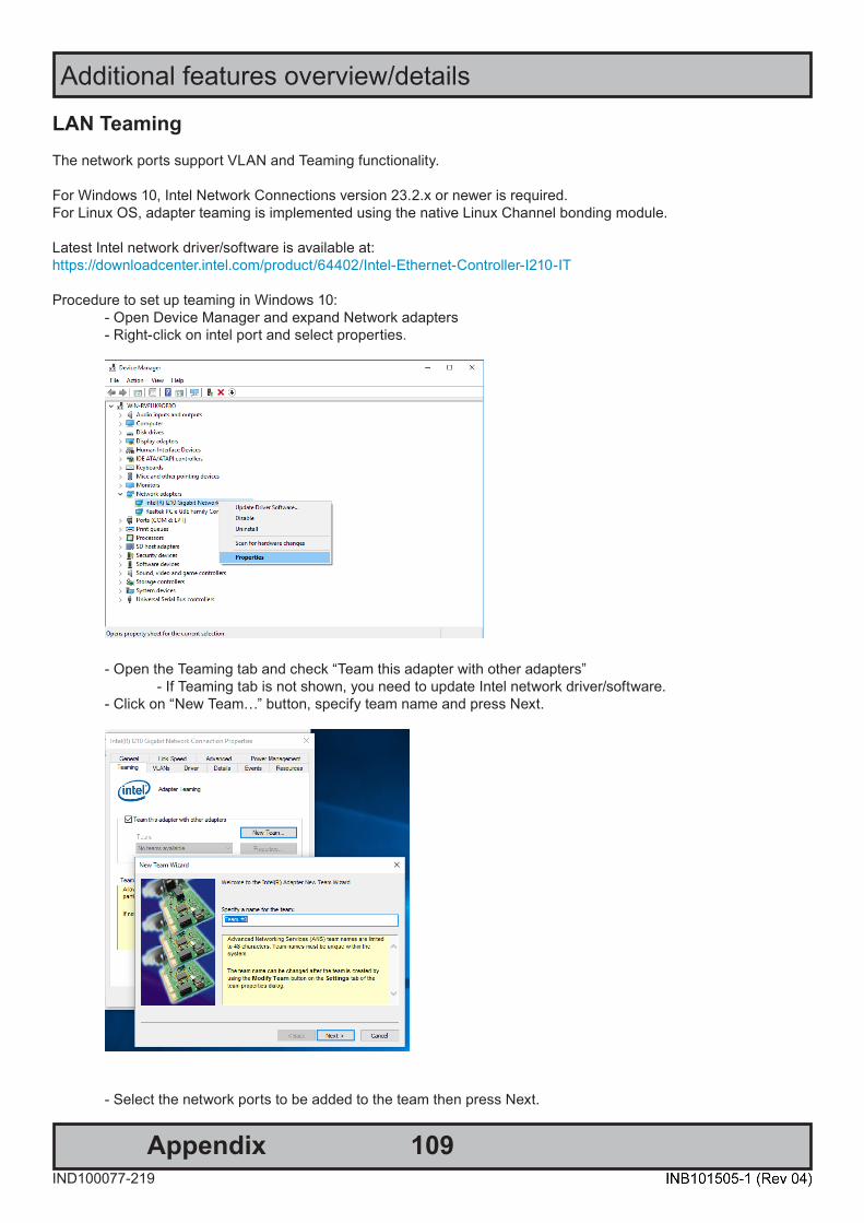
109
Additional features overview/details
AppendixIND100077-219
LAN Teaming The network ports support VLAN and Teaming functionality.
For Windows 10, Intel Network Connections version 23.2.x or newer is required.For Linux OS, adapter teaming is implemented using the native Linux Channel bonding module.
Latest Intel network driver/software is available at:https://downloadcenter.intel.com/product/64402/Intel-Ethernet-Controller-I210-IT
Procedure to set up teaming in Windows 10: - Open Device Manager and expand Network adapters - Right-click on intel port and select properties.
- Open the Teaming tab and check “Team this adapter with other adapters” - If Teaming tab is not shown, you need to update Intel network driver/software. - Click on “New Team…” button, specify team name and press Next.
- Select the network ports to be added to the team then press Next.
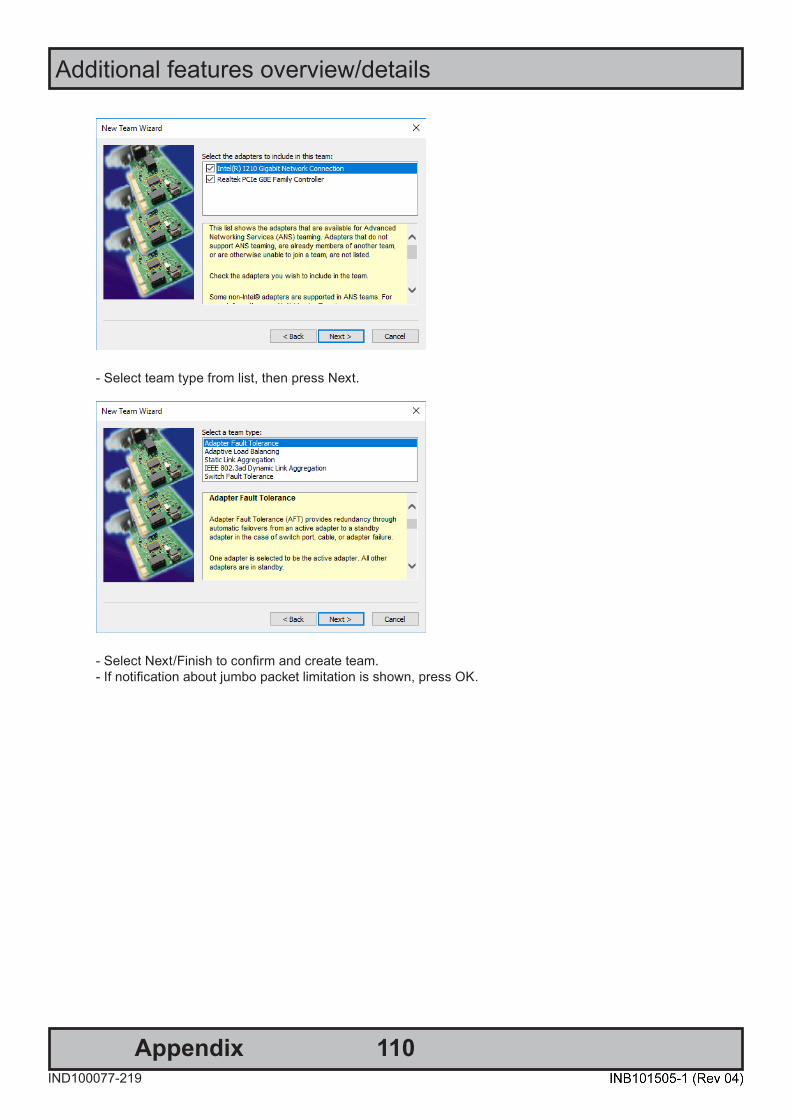
110
Additional features overview/details
AppendixIND100077-219
- Select team type from list, then press Next.
- Select Next/Finish to confirm and create team. - If notification about jumbo packet limitation is shown, press OK.

111
Additional features overview/details
AppendixIND100077-219
Reading internal temperature SCOM* command “TMP” can be used to read out internal temperature sensor value.
*If you are not familiar with the SCOM protocol, please review the Hatteland Technology’s Serial Remote ControlInterface (SCOM) protocol document can be downloaded from:https://www.hattelandtechnology.com/hubfs/pdfget/inb100018-7.htm
Using the eMMC as a backup/recovery device when SSD is used Solution is pending implementation.
- Available for Microsoft® Windows® 10 only.- eMMC will be used as boot and recovery device.- The feature requires an SSD for the Operating System.
The backup is configurable, and can take periodic snapshots of a running system, and restore the unit to this state or factory settings. It will be possible to replace the SSD and restore the unit to the last backup with ease.
In the event of a drive failure or replaced SSD, the system will boot to recovery mode, where the system can be restored.
Install Operating System (OS) For units without factory installed OS:To install any OS on the unit, follow the instructions given by the manufacturer.

112
Additional features overview/details
AppendixIND100077-219
Install Microsoft® Windows® 10 with recovery option1: Boot to Windows 10 installer 2: Select language settings 3: Click “Repair your computer” 4: Click “Troubleshoot” 5: Click “Command Line” and type the following indicated in a black box below.
type diskpart type list disk Take note of which disk number the SSD and eMMC is. This will usually be eMMC=0 and SSD=1
type exit
Step 1 - Prepare disks=======================The contents of the script files will be listed on the end of this section (next page in this manual).Refrence: "Diskpart_Pre-install.txt" and "Diskpart_Post-install.txt"
type diskpart /s \Diskpart_Pre-install.txt
Step 2 - Apply install image======================= type DISM /Apply-Image /ImageFile:\Image\W10LTSC2019.wim /Index:1 /ApplyDir:W:\
Step 3 - Prepare boot sector======================= type cd "W:\Windows\System32"
type bcdboot W:\Windows /s S:
Step 4 - Prepare recovery======================= type md R:\Recovery\WindowsRE
type xcopy /h W:\Windows\System32\Recovery\Winre.wim R:\Recovery\WindowsRE
Step 5 - Finalize disk setup======================= type diskpart /s \Diskpart_Post-install.txt
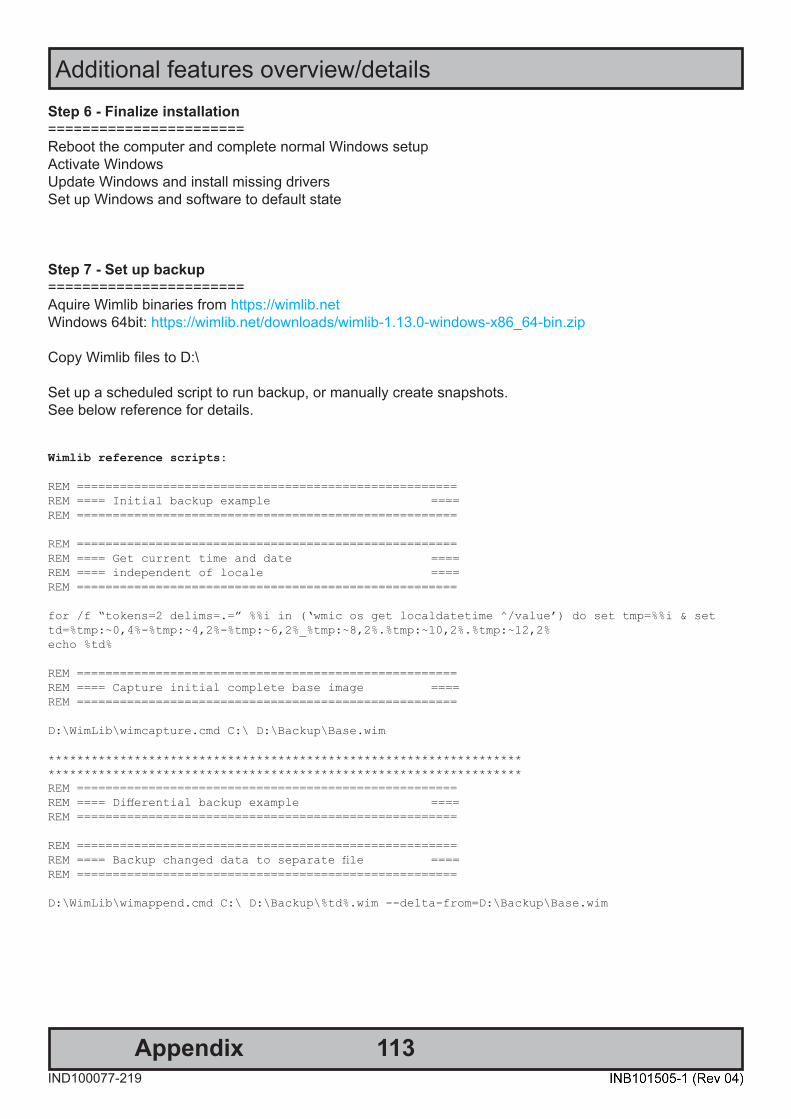
113
Additional features overview/details
AppendixIND100077-219
Step 6 - Finalize installation=======================Reboot the computer and complete normal Windows setupActivate WindowsUpdate Windows and install missing driversSet up Windows and software to default state
Step 7 - Set up backup=======================Aquire Wimlib binaries from https://wimlib.netWindows 64bit: https://wimlib.net/downloads/wimlib-1.13.0-windows-x86_64-bin.zip
Copy Wimlib files to D:\
Set up a scheduled script to run backup, or manually create snapshots.See below reference for details.
Wimlib reference scripts:
REM =====================================================REM ==== Initial backup example ====REM =====================================================
REM =====================================================REM ==== Get current time and date ====REM ==== independent of locale ====REM =====================================================
for /f “tokens=2 delims=.=” %%i in (‘wmic os get localdatetime ^/value’) do set tmp=%%i & set td=%tmp:~0,4%-%tmp:~4,2%-%tmp:~6,2%_%tmp:~8,2%.%tmp:~10,2%.%tmp:~12,2%echo %td%
REM =====================================================REM ==== Capture initial complete base image ====REM =====================================================
D:\WimLib\wimcapture.cmd C:\ D:\Backup\Base.wim
************************************************************************************************************************************REM =====================================================REM ==== Differential backup example ====REM =====================================================
REM =====================================================REM ==== Backup changed data to separate file ====REM =====================================================
D:\WimLib\wimappend.cmd C:\ D:\Backup\%td%.wim --delta-from=D:\Backup\Base.wim
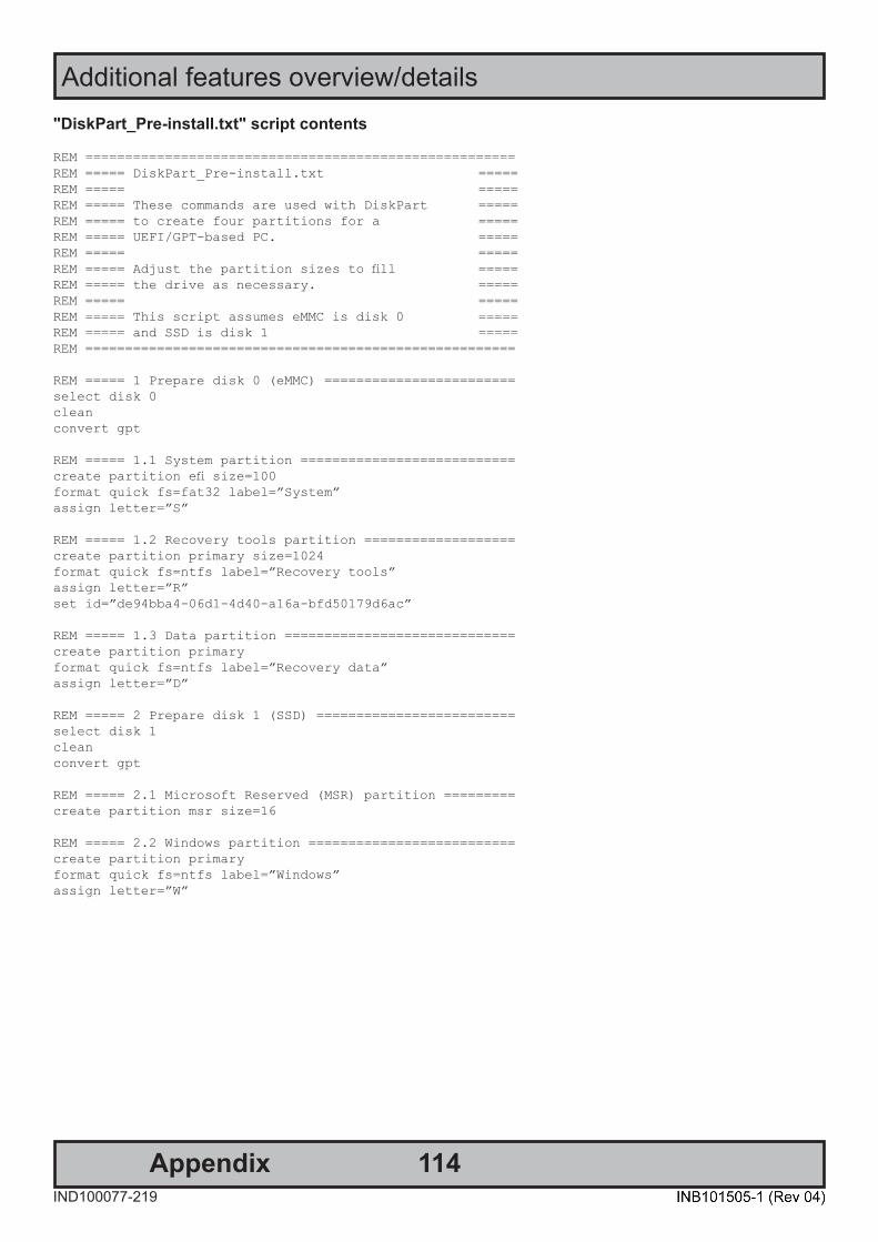
114
Additional features overview/details
AppendixIND100077-219
"DiskPart_Pre-install.txt" script contents
REM ======================================================REM ===== DiskPart_Pre-install.txt =====REM ===== =====REM ===== These commands are used with DiskPart =====REM ===== to create four partitions for a =====REM ===== UEFI/GPT-based PC. =====REM ===== =====REM ===== Adjust the partition sizes to fill =====REM ===== the drive as necessary. =====REM ===== =====REM ===== This script assumes eMMC is disk 0 =====REM ===== and SSD is disk 1 =====REM ======================================================
REM ===== 1 Prepare disk 0 (eMMC) ========================select disk 0cleanconvert gpt
REM ===== 1.1 System partition ===========================create partition efi size=100format quick fs=fat32 label=”System”assign letter=”S”
REM ===== 1.2 Recovery tools partition ===================create partition primary size=1024format quick fs=ntfs label=”Recovery tools”assign letter=”R”set id=”de94bba4-06d1-4d40-a16a-bfd50179d6ac”
REM ===== 1.3 Data partition =============================create partition primaryformat quick fs=ntfs label=”Recovery data”assign letter=”D”
REM ===== 2 Prepare disk 1 (SSD) =========================select disk 1cleanconvert gpt
REM ===== 2.1 Microsoft Reserved (MSR) partition =========create partition msr size=16
REM ===== 2.2 Windows partition ==========================create partition primaryformat quick fs=ntfs label=”Windows”assign letter=”W”

115
Additional features overview/details
AppendixIND100077-219
"DiskPart_Post-install.txt" script contents
REM ================================================REM ===== DiskPart_Post-install.txt =====REM ===== Post install script =====REM ===== =====REM ===== This should be run after copying =====REM ===== WinRE to recovery partition =====REM ================================================
REM ================================================REM ===== 1 Setting hidden flag for =====REM ===== Recovery partition =====REM ================================================Select disk 0select partition 2gpt attributes=0x8000000000000001
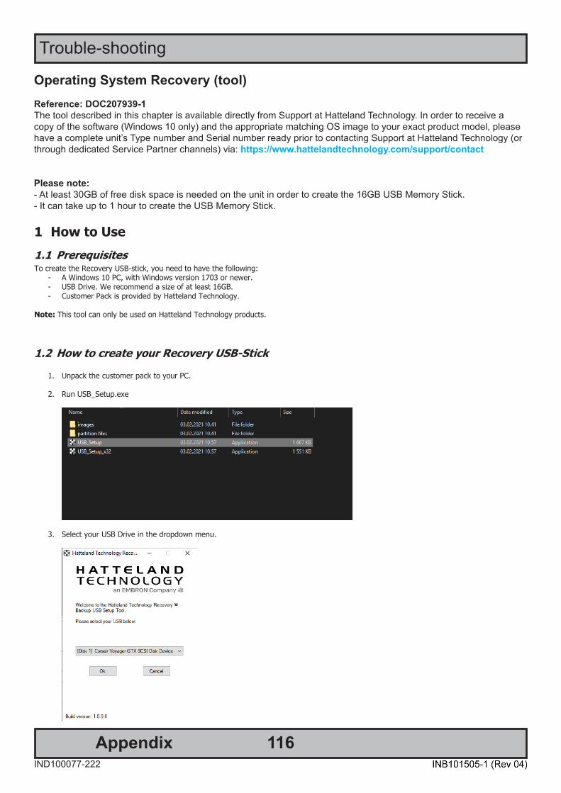
116IND100077-222
Appendix
Trouble-shooting
Operating System Recovery (tool) Reference: DOC207939-1The tool described in this chapter is available directly from Support at Hatteland Technology. In order to receive a copy of the software (Windows 10 only) and the appropriate matching OS image to your exact product model, please have a complete unit’s Type number and Serial number ready prior to contacting Support at Hatteland Technology (or through dedicated Service Partner channels) via: https://www.hattelandtechnology.com/support/contact
Please note:- At least 30GB of free disk space is needed on the unit in order to create the 16GB USB Memory Stick.- It can take up to 1 hour to create the USB Memory Stick.
DOC207939-1 - Revision 03
Hatteland Technology AS | www.hattelandtechnology.com | Enterprise no: NO974533146 Page 4 of 7
1 How to Use 1.1 Prerequisites To create the Recovery USB-stick, you need to have the following:
- A Windows 10 PC, with Windows version 1703 or newer. - USB Drive. We recommend a size of at least 16GB. - Customer Pack is provided by Hatteland Technology.
Note: This tool can only be used on Hatteland Technology products.
1.2 How to create your Recovery USB-Stick
1. Unpack the customer pack to your PC.
2. Run USB_Setup.exe
3. Select your USB Drive in the dropdown menu.
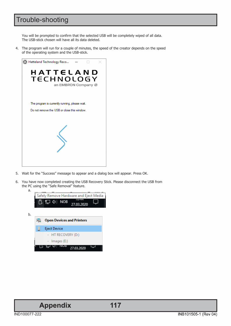
117IND100077-222
Trouble-shooting
Appendix
DOC207939-1 - Revision 03
Hatteland Technology AS | www.hattelandtechnology.com | Enterprise no: NO974533146 Page 5 of 7
You will be prompted to confirm that the selected USB will be completely wiped of all data. The USB-stick chosen will have all its data deleted.
4. The program will run for a couple of minutes, the speed of the creator depends on the speed of the operating system and the USB-stick.
5. Wait for the “Success” message to appear and a dialog box will appear. Press OK.
6. You have now completed creating the USB Recovery Stick. Please disconnect the USB from the PC using the “Safe Removal” feature.
a.
b.
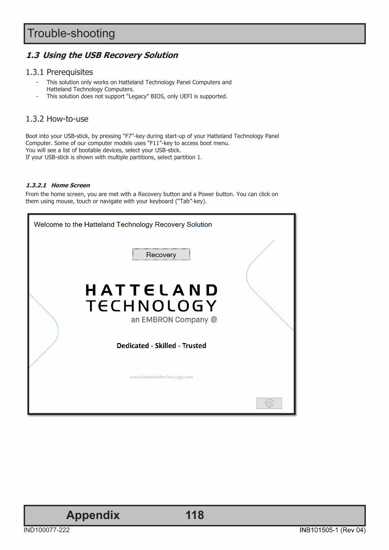
118IND100077-222
Trouble-shooting
Appendix
DOC207939-1 - Revision 03
Hatteland Technology AS | www.hattelandtechnology.com | Enterprise no: NO974533146 Page 6 of 7
1.3 Using the USB Recovery Solution
1.3.1 Prerequisites - This solution only works on Hatteland Technology Panel Computers and
Hatteland Technology Computers. - This solution does not support “Legacy” BIOS, only UEFI is supported.
1.3.2 How-to-use
Boot into your USB-stick, by pressing “F7”-key during start-up of your Hatteland Technology Panel Computer. Some of our computer models uses “F11”-key to access boot menu. You will see a list of bootable devices, select your USB-stick. If your USB-stick is shown with multiple partitions, select partition 1.
1.3.2.1 Home Screen From the home screen, you are met with a Recovery button and a Power button. You can click on them using mouse, touch or navigate with your keyboard (“Tab”-key).

119IND100077-222
Trouble-shooting
Appendix
DOC207939-1 - Revision 03
Hatteland Technology AS | www.hattelandtechnology.com | Enterprise no: NO974533146 Page 7 of 7
1.3.2.2 Recovery The Recovery buttons opens the recovery function. You select the target drive you wish to recover. The description in the large box is the description of the image. When you press “ok”, you will get a final warning that the target drive will be wiped and all data on the drive will be lost. After pressing “yes”, the program will do everything needed for the recovery automatically. When finished, you are asked to restart or shut down your computer. Please disconnect your USB-stick after restarting or shutting down.
DOC207939-1 - Revision 03
Hatteland Technology AS | www.hattelandtechnology.com | Enterprise no: NO974533146 Page 3 of 7
Revision History
Created Approved
Rev Date By Date By Description
1 2020.07.16 Yrjan Rein 2020.07.22 Gunnar Myklebust
Initial Version
2 2021.02.03 Yrjan Rein 2021.02.04 Morten Mæland Updated Pictures. Removed chapter that is not relevant to the function of “recovery only”. Updated name of the USB setup executable.
3
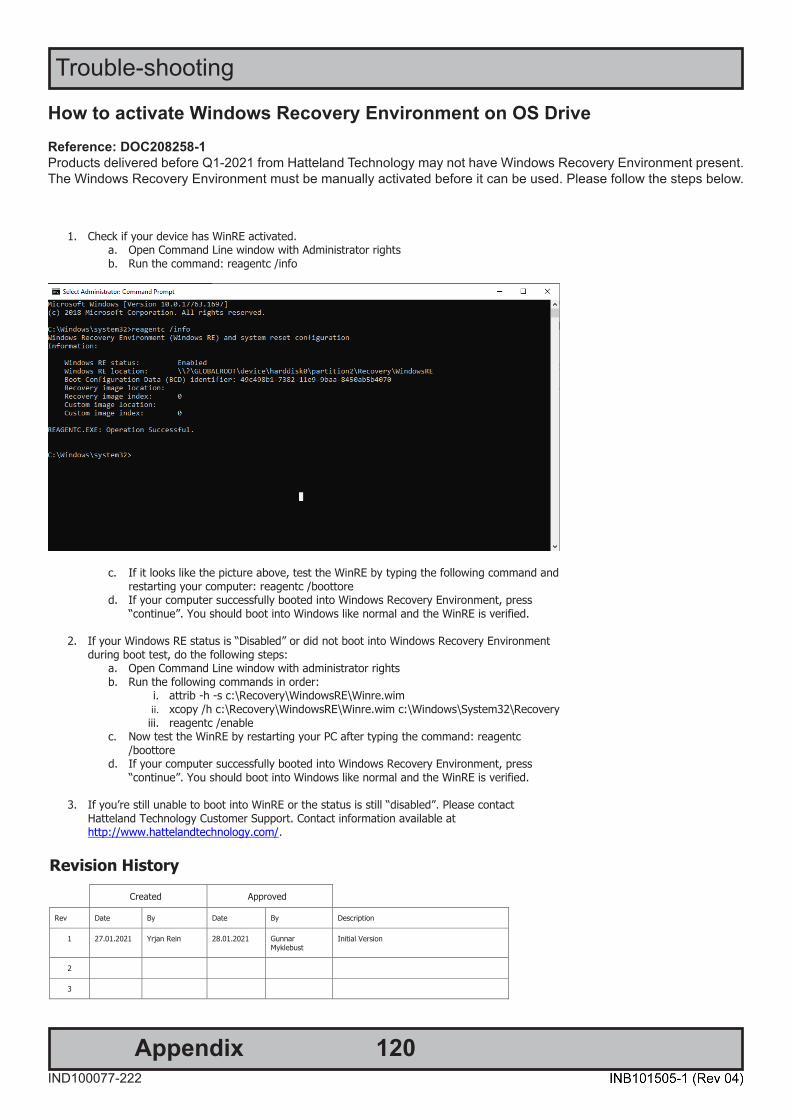
120IND100077-222
Trouble-shooting
Appendix
How to activate Windows Recovery Environment on OS Drive Reference: DOC208258-1Products delivered before Q1-2021 from Hatteland Technology may not have Windows Recovery Environment present.The Windows Recovery Environment must be manually activated before it can be used. Please follow the steps below.
DOC208258-1 - Revision 01
Hatteland Technology AS | www.hattelandtechnology.com | Enterprise no: NO974533146 Page 2 of 2
How to activate WinRE
1. Check if your device has WinRE activated. a. Open Command Line window with Administrator rights b. Run the command: reagentc /info
c. If it looks like the picture above, test the WinRE by typing the following command and restarting your computer: reagentc /boottore
d. If your computer successfully booted into Windows Recovery Environment, press “continue”. You should boot into Windows like normal and the WinRE is verified.
2. If your Windows RE status is “Disabled” or did not boot into Windows Recovery Environment during boot test, do the following steps:
a. Open Command Line window with administrator rights b. Run the following commands in order:
i. attrib -h -s c:\Recovery\WindowsRE\Winre.wim ii. xcopy /h c:\Recovery\WindowsRE\Winre.wim c:\Windows\System32\Recovery iii. reagentc /enable
c. Now test the WinRE by restarting your PC after typing the command: reagentc /boottore
d. If your computer successfully booted into Windows Recovery Environment, press “continue”. You should boot into Windows like normal and the WinRE is verified.
3. If you’re still unable to boot into WinRE or the status is still “disabled”. Please contact Hatteland Technology Customer Support. Contact information available at http://www.hattelandtechnology.com/.
DOC208258-1 - Revision 01
Hatteland Technology AS | www.hattelandtechnology.com | Enterprise no: NO974533146 Page 1 of 2
DOC208258-1
How to activate WinRE on OS drive
Revision History Created Approved
Rev Date By Date By Description
1 27.01.2021 Yrjan Rein 28.01.2021 Gunnar Myklebust
Initial Version
2
3
121AppendixIND100077-195
RTC Timer (Apollolake) - User Guide
DOC207017- rev 01 – 2018-09-24 - Created by: 6644
Page 1 of 12 Hatteland Display AS, Stokkastrandvegen 87B, N-5578 Nedre Vats, Norway
Tel: (+47) 4814 2200 - [email protected] - www.hatteland-display.com
User Guide RTC Timer - ApolloLake All intellectual properties belongs to Hatteland Display AS
User Guide
RTC Timer (ApolloLake)
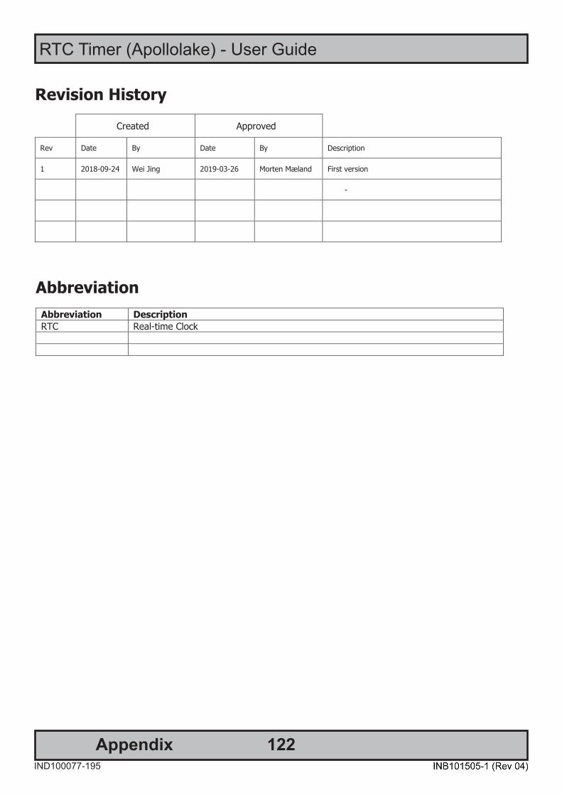
122
RTC Timer (Apollolake) - User Guide
AppendixIND100077-195
DOC207017- rev 01 – 2018-09-24 - Created by: 6644
Page 3 of 12 Hatteland Display AS, Stokkastrandvegen 87B, N-5578 Nedre Vats, Norway
Tel: (+47) 4814 2200 - [email protected] - www.hatteland-display.com
User Guide RTC Timer - ApolloLake All intellectual properties belongs to Hatteland Display AS
Revision History
Abbreviation Abbreviation Description RTC Real-time Clock
Created Approved
Rev Date By Date By Description
1 2018-09-24 Wei Jing 2019-03-26 Morten Mæland First version
-
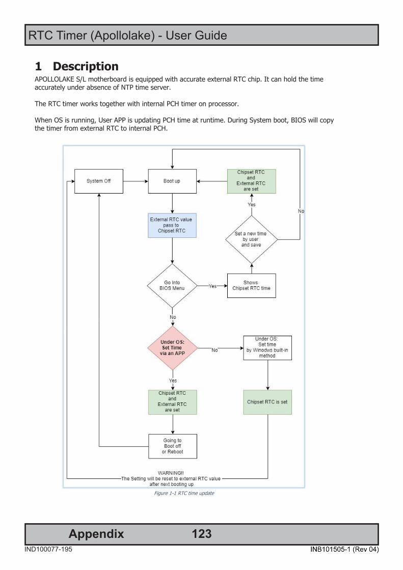
123
RTC Timer (Apollolake) - User Guide
AppendixIND100077-195
DOC207017- rev 01 – 2018-09-24 - Created by: 6644
Page 4 of 12 Hatteland Display AS, Stokkastrandvegen 87B, N-5578 Nedre Vats, Norway
Tel: (+47) 4814 2200 - [email protected] - www.hatteland-display.com
User Guide RTC Timer - ApolloLake All intellectual properties belongs to Hatteland Display AS
1 Description APOLLOLAKE S/L motherboard is equipped with accurate external RTC chip. It can hold the time accurately under absence of NTP time server.
The RTC timer works together with internal PCH timer on processor. When OS is running, User APP is updating PCH time at runtime. During System boot, BIOS will copy the timer from external RTC to internal PCH.
DOC207017- rev 01 – 2018-09-24 - Created by: 6644
Page 5 of 12 Hatteland Display AS, Stokkastrandvegen 87B, N-5578 Nedre Vats, Norway
Tel: (+47) 4814 2200 - [email protected] - www.hatteland-display.com
User Guide RTC Timer - ApolloLake All intellectual properties belongs to Hatteland Display AS
Figure 1-1 RTC time update
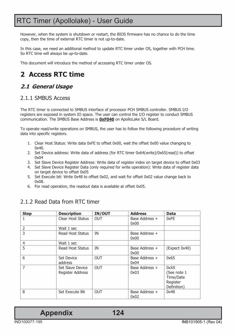
124
RTC Timer (Apollolake) - User Guide
AppendixIND100077-195
DOC207017- rev 01 – 2018-09-24 - Created by: 6644
Page 6 of 12 Hatteland Display AS, Stokkastrandvegen 87B, N-5578 Nedre Vats, Norway
Tel: (+47) 4814 2200 - [email protected] - www.hatteland-display.com
User Guide RTC Timer - ApolloLake All intellectual properties belongs to Hatteland Display AS
However, when the system is shutdown or restart, the BIOS firmware has no chance to do the time copy, then the time of external RTC timer is not up-to-date. In this case, we need an additional method to update RTC timer under OS, together with PCH time. So RTC time will always be up-to-date. This document will introduce the method of accessing RTC timer under OS.
2 Access RTC time
2.1 General Usage
2.1.1 SMBUS Access The RTC timer is connected to SMBUS interface of processor PCH SMBUS controller. SMBUS I/O registers are exposed in system IO space. The user can control the I/O register to conduct SMBUS communication. The SMBUS Base Address is 0xF040 on ApolloLake S/L Board. To operate read/write operations on SMBUS, the user has to follow the following procedure of writing data into specific registers.
1. Clear Host Status: Write data 0xFE to offset 0x00, wait the offset 0x00 value changing to 0x40.
2. Set Device address: Write data of address (for RTC timer 0x64(write)/0x65(read)) to offset 0x04
3. Set Slave Device Register Address: Write data of register index on target device to offset 0x03 4. Set Slave Device Register Data (only required for write operation): Write data of register data
on target device to offset 0x05 5. Set Execute bit: Write 0x48 to offset 0x02, and wait for offset 0x02 value change back to
0x08. 6. For read operation, the readout data is available at offset 0x05.
2.1.2 Read Data from RTC timer Step Description IN/OUT Address Data 1 Clear Host Status OUT Base Address +
0x00 0xFE
2 Wait 1 sec 3 Read Host Status IN Base Address +
0x00
4 Wait 1 sec 5 Read Host Status IN Base Address +
0x00 (Expect 0x40)
6 Set Device address
OUT Base Address + 0x04
0x65
7 Set Slave Device Register Address
OUT Base Address + 0x03
0xXX (See note 1 Time/Date Register Definition)
8 Set Execute Bit OUT Base Address + 0x02
0x48

125
RTC Timer (Apollolake) - User Guide
AppendixIND100077-195
DOC207017- rev 01 – 2018-09-24 - Created by: 6644
Page 7 of 12 Hatteland Display AS, Stokkastrandvegen 87B, N-5578 Nedre Vats, Norway
Tel: (+47) 4814 2200 - [email protected] - www.hatteland-display.com
User Guide RTC Timer - ApolloLake All intellectual properties belongs to Hatteland Display AS
9 Wait 1 sec 10 Read Execute Bit IN Base Address +
0x02 (Expected 0x08)
11 Read Returned data
IN Base Address + 0x05
(See note 1 Time/Date Register Definition)
Note:
1. Time/Date Register definition in RTC timer
2.1.3 Write Data to RTC timer Step Description IN/OUT Address Data 1 Clear Host Status OUT Base Address +
0x00 0xFE
2 Wait 1 sec 3 Read Host Status IN Base Address +
0x00
4 Wait 1 sec 5 Read Host Status IN Base Address +
0x00 (Expect 0x40)
6 Set Device address
OUT Base Address + 0x04
0x64
7 Set Slave Device Register Address
OUT Base Address + 0x03
0xXX (See note 1 Time/Date Register Definition)
8 Set Slave Device Register Data
OUT Base Address + 0x05
0xXX (See note 1 Time/Date Register Definition)
9 Set Execute Bit OUT Base Address + 0x02
0x48
10 Wait 1 sec 11 Read Execute Bit IN Base Address +
0x02 (Expected 0x08)
Note:

126
RTC Timer (Apollolake) - User Guide
AppendixIND100077-195
DOC207017- rev 01 – 2018-09-24 - Created by: 6644
Page 8 of 12 Hatteland Display AS, Stokkastrandvegen 87B, N-5578 Nedre Vats, Norway
Tel: (+47) 4814 2200 - [email protected] - www.hatteland-display.com
User Guide RTC Timer - ApolloLake All intellectual properties belongs to Hatteland Display AS
1. Time/Date Register definition in RTC timer
3 Driver support
3.1 Windows Windows does not provide direct IO address access in user-space, so a third party driver/library is required to implement the IO control logic in application. Here we recommend a method of 3rd party driver: Inpout driver. http://www.highrez.co.uk/downloads/inpout32/default.htm “ The InpOut32 device driver supports writing to "old fashioned" hardware port addresses. It does NOT support USB devices such as USB Parallel ports or even PCI parallel ports. The device driver is installed at runtime. To do this however needs administrator privileges. On Vista & later, using UAC, you can run the InstallDriver.exe in the \Win32 folder to install the driver appropriate for your OS. Doing so will request elevation and ask for your permission (or for the administrator password). Once the driver is installed for the first time, it can then be used by any user *without* administrator privileges “[1] The inpout driver package consists of:
- Driver: Inpout.sys - DLL file: Inpout.dll
Driver file is required to install beforehand. Then the user application call the provided interface to read/write on IO port:
1. Set Output to IO port. void Out32(short Address, short Data);
2. Read Input from IO address short Inp32(short Address);
3. Check if InpOut driver is opened. BOOL IsInpOutDriverOpen(void);
3.1.1 Example Code Windows typedef void (__stdcall *lpOut32)(short, short);
DOC207017- rev 01 – 2018-09-24 - Created by: 6644
Page 7 of 12 Hatteland Display AS, Stokkastrandvegen 87B, N-5578 Nedre Vats, Norway
Tel: (+47) 4814 2200 - [email protected] - www.hatteland-display.com
User Guide RTC Timer - ApolloLake All intellectual properties belongs to Hatteland Display AS
9 Wait 1 sec 10 Read Execute Bit IN Base Address +
0x02 (Expected 0x08)
11 Read Returned data
IN Base Address + 0x05
(See note 1 Time/Date Register Definition)
Note:
1. Time/Date Register definition in RTC timer
2.1.3 Write Data to RTC timer Step Description IN/OUT Address Data 1 Clear Host Status OUT Base Address +
0x00 0xFE
2 Wait 1 sec 3 Read Host Status IN Base Address +
0x00
4 Wait 1 sec 5 Read Host Status IN Base Address +
0x00 (Expect 0x40)
6 Set Device address
OUT Base Address + 0x04
0x64
7 Set Slave Device Register Address
OUT Base Address + 0x03
0xXX (See note 1 Time/Date Register Definition)
8 Set Slave Device Register Data
OUT Base Address + 0x05
0xXX (See note 1 Time/Date Register Definition)
9 Set Execute Bit OUT Base Address + 0x02
0x48
10 Wait 1 sec 11 Read Execute Bit IN Base Address +
0x02 (Expected 0x08)
Note:

127
RTC Timer (Apollolake) - User Guide
AppendixIND100077-195
DOC207017- rev 01 – 2018-09-24 - Created by: 6644
Page 9 of 12 Hatteland Display AS, Stokkastrandvegen 87B, N-5578 Nedre Vats, Norway
Tel: (+47) 4814 2200 - [email protected] - www.hatteland-display.com
User Guide RTC Timer - ApolloLake All intellectual properties belongs to Hatteland Display AS
typedef short (__stdcall *lpInp32)(short); lpOut32 gfpOut32; lpInp32 gfpInp32; //Base Address Read unsigned char SlaveDeviceReadByte(unsigned char bSlaveDeviceAddr, unsigned char bSlaveRegisterAddr) { unsigned char bValue = 0; //1. Clear host status gfpOut32(iBaseAddrSMBUS + bOffsetHostStatus, 0xFE); //2. Wait for 2 sec Sleep(1000); //3. Read Host Status bValue = (unsigned char)gfpInp32(iBaseAddrSMBUS + bOffsetHostStatus); Sleep(1000); bValue = (unsigned char)gfpInp32(iBaseAddrSMBUS + bOffsetHostStatus); if(bValue != 0x40) { //Error } //4. Set Device address gfpOut32(iBaseAddrSMBUS + bOffsetSlaveDeviceAddress, bSlaveDeviceAddr); //5. Set Slave register address gfpOut32(iBaseAddrSMBUS + bOffsetSlaveRegisterAddress, bSlaveRegisterAddr); //6. Set Execute bit gfpOut32(iBaseAddrSMBUS + bOffsetExecute, 0x48); //7. Wait 1 sec Sleep(1000); //8. Read Execute bit bValue = (unsigned char)gfpInp32(iBaseAddrSMBUS + bOffsetExecute); if(bValue != 0x08) { //Error } //9. Read returned data bValue = (unsigned char)gfpInp32(iBaseAddrSMBUS + bOffsetSlaveRegisterData); return bValue; } void SlaveDeviceWriteByte(unsigned char bSlaveDeviceAddr, unsigned char bSlaveRegisterAddr, unsigned char bSlaveRegisterData) {
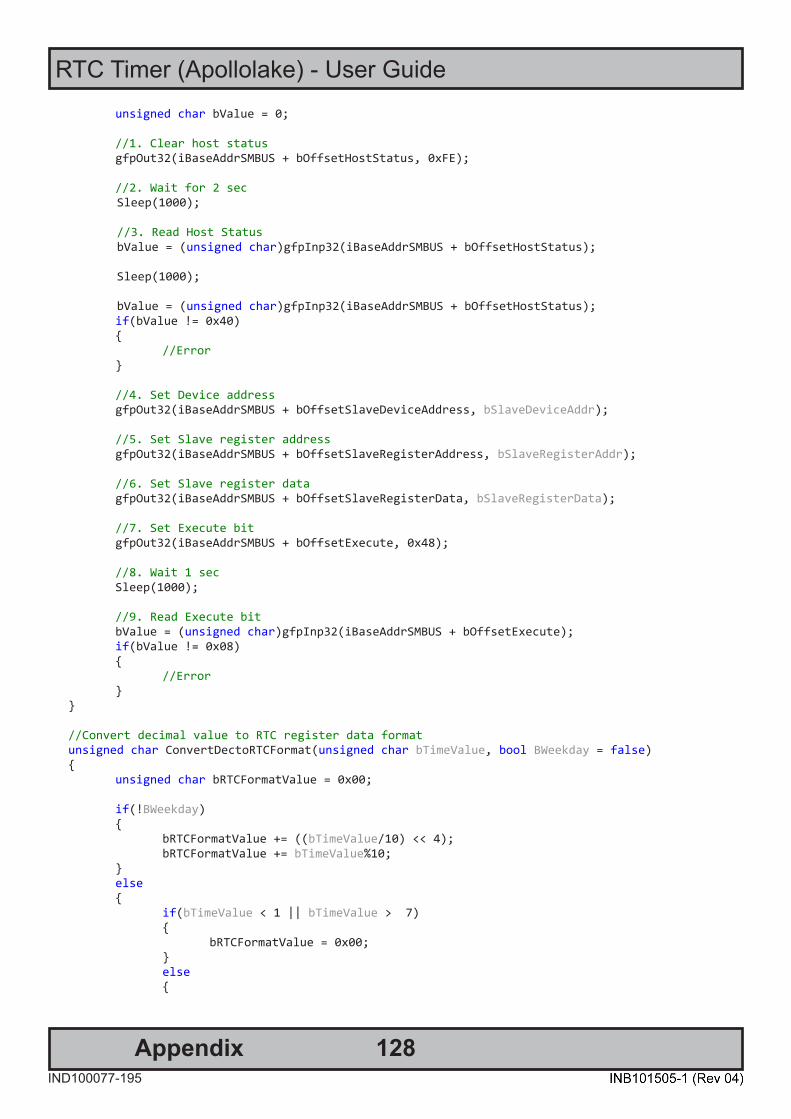
128
RTC Timer (Apollolake) - User Guide
AppendixIND100077-195
DOC207017- rev 01 – 2018-09-24 - Created by: 6644
Page 10 of 12 Hatteland Display AS, Stokkastrandvegen 87B, N-5578 Nedre Vats, Norway
Tel: (+47) 4814 2200 - [email protected] - www.hatteland-display.com
User Guide RTC Timer - ApolloLake All intellectual properties belongs to Hatteland Display AS
unsigned char bValue = 0; //1. Clear host status gfpOut32(iBaseAddrSMBUS + bOffsetHostStatus, 0xFE); //2. Wait for 2 sec Sleep(1000); //3. Read Host Status bValue = (unsigned char)gfpInp32(iBaseAddrSMBUS + bOffsetHostStatus); Sleep(1000); bValue = (unsigned char)gfpInp32(iBaseAddrSMBUS + bOffsetHostStatus); if(bValue != 0x40) { //Error } //4. Set Device address gfpOut32(iBaseAddrSMBUS + bOffsetSlaveDeviceAddress, bSlaveDeviceAddr); //5. Set Slave register address gfpOut32(iBaseAddrSMBUS + bOffsetSlaveRegisterAddress, bSlaveRegisterAddr); //6. Set Slave register data gfpOut32(iBaseAddrSMBUS + bOffsetSlaveRegisterData, bSlaveRegisterData); //7. Set Execute bit gfpOut32(iBaseAddrSMBUS + bOffsetExecute, 0x48); //8. Wait 1 sec Sleep(1000); //9. Read Execute bit bValue = (unsigned char)gfpInp32(iBaseAddrSMBUS + bOffsetExecute); if(bValue != 0x08) { //Error } } //Convert decimal value to RTC register data format unsigned char ConvertDectoRTCFormat(unsigned char bTimeValue, bool BWeekday = false) { unsigned char bRTCFormatValue = 0x00; if(!BWeekday) { bRTCFormatValue += ((bTimeValue/10) << 4); bRTCFormatValue += bTimeValue%10; } else { if(bTimeValue < 1 || bTimeValue > 7) { bRTCFormatValue = 0x00; } else {
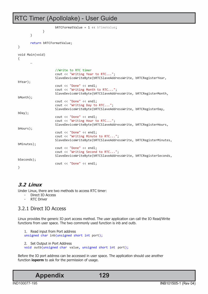
129
RTC Timer (Apollolake) - User Guide
AppendixIND100077-195
DOC207017- rev 01 – 2018-09-24 - Created by: 6644
Page 11 of 12 Hatteland Display AS, Stokkastrandvegen 87B, N-5578 Nedre Vats, Norway
Tel: (+47) 4814 2200 - [email protected] - www.hatteland-display.com
User Guide RTC Timer - ApolloLake All intellectual properties belongs to Hatteland Display AS
bRTCFormatValue = 1 << bTimeValue; } } return bRTCFormatValue; } void Main(void) { … //Write to RTC timer cout << "Writing Year to RTC..."; SlaveDeviceWriteByte(bRTCSlaveAddressWrite, bRTCRegisterYear, bYear); cout << "Done" << endl; cout << "Writing Month to RTC..."; SlaveDeviceWriteByte(bRTCSlaveAddressWrite, bRTCRegisterMonth, bMonth); cout << "Done" << endl; cout << "Writing Day to RTC..."; SlaveDeviceWriteByte(bRTCSlaveAddressWrite, bRTCRegisterDay, bDay); cout << "Done" << endl; cout << "Writing Hour to RTC..."; SlaveDeviceWriteByte(bRTCSlaveAddressWrite, bRTCRegisterHours, bHours); cout << "Done" << endl; cout << "Writing Minute to RTC..."; SlaveDeviceWriteByte(bRTCSlaveAddressWrite, bRTCRegisterMinutes, bMinutes); cout << "Done" << endl; cout << "Writing Second to RTC..."; SlaveDeviceWriteByte(bRTCSlaveAddressWrite, bRTCRegisterSeconds, bSeconds); cout << "Done" << endl; }
3.2 Linux Under Linux, there are two methods to access RTC timer:
- Direct IO Access - RTC Driver
3.2.1 Direct IO Access Linux provides the generic IO port access method. The user application can call the IO Read/Write functions from user space. The two commonly used function is inb and outb.
1. Read input from Port address unsigned char inb(unsigned short int port); 2. Set Output in Port Address void outb(unsigned char value, unsigned short int port);
Before the IO port address can be accessed in user space. The application should use another function ioperm to ask for the permission of usage.

130
RTC Timer (Apollolake) - User Guide
AppendixIND100077-195
DOC207017- rev 01 – 2018-09-24 - Created by: 6644
Page 12 of 12 Hatteland Display AS, Stokkastrandvegen 87B, N-5578 Nedre Vats, Norway
Tel: (+47) 4814 2200 - [email protected] - www.hatteland-display.com
User Guide RTC Timer - ApolloLake All intellectual properties belongs to Hatteland Display AS
ioperm() sets the port access permission bits for the calling thread for num bits starting from port addressfrom. If turn_on is nonzero, then permission for the specified bits is enabled; otherwise it is disabled. Ifturn_on is nonzero, the calling thread must be privileged. [2]
int ioperm(unsigned long from, unsigned long num, int turn_on);
3.2.2 RTC Driver RTC Chip RV8803 is generically supported by Linux Kernel 4.4 and above. The user can use standard RTC system calls to read, write date/time in external RTC timer.
4 Note
1. It is not recommended to operate read/write too frequently, because heavy load on this bus may affect internal system devices working improperly.
2. It is always suggested to change RTC time at the same time when changing OS time/PCH
time. Windows 10 refuses all the backwards date change in RTC. So when the date in RTC is changed to earlier date and different from Windows date, Windows will ignore the date/time change by RTC. For example, If user is changing RTC time from 01/10/2017 to 03/03/2015, by accessing RTC date in OS. But the OS date is not updated accordingly. Then power input is cut off by accident. This causes a mismatch between PCH date and RTC date. In next boot, the PCH date is updated to 03/03/2015, but OS reject this earlier date and keep using 01/10/2017. In this case the date must be changed manually before Windows will do automatic changes.
5 Reference [1] InpOut32 and InpOutx64, http://www.highrez.co.uk/downloads/inpout32/default.htm [2] ioperm(2) - Linux man page http://linux.die.net/man/2/ioperm
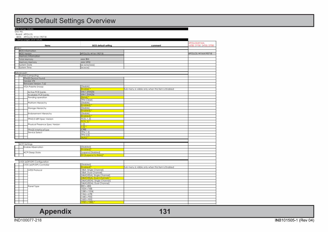
131AppendixIND100077-218
BIOS Default Settings OverviewBIOS Setup Values
Doc No.
Board: APOLLOL
BIOS: APOLLOL-W1M-190718
1. Setup pages and values
Items BIOS default setting comment
Main>
BIOS Information
BIOS Version APOLLOL-W1M-190718 APOLLOL-W1MA190718
Memory Information
Total Memory xxxx BM
Memory Memory xxxx MHzSystem Date [xx xx/xx/xxxx]
System Time [xx:xx:xx]
Advanced>
Trusted Computing
TPM20 Device Found
Vendor: IFX
Firmware Version: 7.62
VGA Palette Snoop [Disable]
[Enable] * Sub menu is visible only when this item is Enabled
Active PCR banks SHA-1,SHA256
Available PCR banks SHA-1,SHA256
Pending operation [None] *
[TPM Clear]
Platform Hierarchy [Disable]
[Enabled] *
Storage Hierarchy [Disable]
[Enabled] *
Endorsement Hierarchy [Disable]
[Enabled] *
TPM2.0 UEFI Spec Version [TCG_1_2]
[TCG_2] *
Physical Presence Spec Version [1.2]
[1.3] *
TPM20 InterfaceType [CRB]
Device Select [TPM 1.2]
[TPM 2.0]
[Auto] *
ACPI Settings
Enable Hibernation [Disabled]
[Enabled]*
ACPI Sleep State [Suspend Disabled]
[S3 (Suspend to RAM)]*
LVDS (eDP/DP) Configuration
LVDS (eDP/DP) Controller [Disabled]
[Enabled]* Sub menu is visible only when this item is Enabled
LVDS Protocol [18bit, Single Channel]
[18bit, Dual Channel]
[24bit(VESA), Single Channel]
[24bit(VESA), Dual Channel] *
[24bit(JEIDA), Single Channel]
[24bit(JEIDA), Dual Channel]
Panel Type [800 x 480]
[1024 x 768]
[1280 x 1024]
[1366 x 678]
[1440 x 900]
[1600 x 900]
[1920 x 1080] *
Power Configuration
Power Mode
APOLLOLW1MA16T30, 21T30, 24T30, 27T30

132AppendixIND100077-218
BIOS Default Settings Overview
Internal USB 3.0 -1 [Disabled] *
[Enabled]
Internal USB 3.0 -2 [Disabled] *
[Enabled]
USB port 4 on Terminal (top) [Disabled] *
[Enabled]
USB port 3 on Terminal [Disabled] *
[Enabled]
USB port 2 on Terminal [Disabled] *
[Enabled]
USB port 1 on Terminal (bottom) [Disabled] *
[Enabled]
Internal USB 2.0 -1 [Disabled] *
[Enabled]
Internal USB 2.0 -2 [Disabled] *
[Enabled]
Reset Mode
Internal USB 3.0 -1 [Disabled] *
[Enabled]
Internal USB 3.0 -2 [Disabled] *
[Enabled]
USB port 4 on Terminal (top) [Disabled] *
[Enabled]
USB port 3 on Terminal [Disabled] *
[Enabled]
USB port 2 on Terminal [Disabled] *
[Enabled]
USB port 1 on Terminal (bottom) [Disabled] *
[Enabled]
Internal USB 2.0 -1 [Disabled] *
[Enabled]
Internal USB 2.0 -2 [Disabled] *
[Enabled]
Panel power
panel power control [Disabled]
[Enabled] *
panel supply voltage [3.3V]
[5V] *
RTC Battery Alarm Voltage
RTC Battery Alarm Voltage
[Disabled] [Disabled]
[2.0V] * [2.0V]
[2.1V] [2.1V]
[2.2V] [2.2V]
[2.3V] [2.3V]
[2.4V] [2.4V] *
[2.5V] [2.5V]
[2.6V] [2.6V]
[2.7V] [2.7V]
[2.8V] [2.8V]
[2.9V] [2.9V]
[3.0V] [3.0V]
SCOM Bus Settings
SCOM Bus Status Working
Type No. N/A
Serial No. N/A
FW Version FW100005-TA09
Keypad No Keypad
IO Card No IO Card
Buzzer Off[Disabled]
[Enabled] *
Power Mode
[Always On] *
[Power Button Only]
[Previous State]
External RTC Configuration
Auto Sync RTC[Disabled] *
[Enabled]
BIOS Setup Values
Doc No.
Board: APOLLOL
BIOS: APOLLOL-W1M-190718
1. Setup pages and values
Items BIOS default setting comment
Main>
BIOS Information
BIOS Version APOLLOL-W1M-190718 APOLLOL-W1MA190718
Memory Information
Total Memory xxxx BM
Memory Memory xxxx MHzSystem Date [xx xx/xx/xxxx]
System Time [xx:xx:xx]
Advanced>
Trusted Computing
TPM20 Device Found
Vendor: IFX
Firmware Version: 7.62
VGA Palette Snoop [Disable]
[Enable] * Sub menu is visible only when this item is Enabled
Active PCR banks SHA-1,SHA256
Available PCR banks SHA-1,SHA256
Pending operation [None] *
[TPM Clear]
Platform Hierarchy [Disable]
[Enabled] *
Storage Hierarchy [Disable]
[Enabled] *
Endorsement Hierarchy [Disable]
[Enabled] *
TPM2.0 UEFI Spec Version [TCG_1_2]
[TCG_2] *
Physical Presence Spec Version [1.2]
[1.3] *
TPM20 InterfaceType [CRB]
Device Select [TPM 1.2]
[TPM 2.0]
[Auto] *
ACPI Settings
Enable Hibernation [Disabled]
[Enabled]*
ACPI Sleep State [Suspend Disabled]
[S3 (Suspend to RAM)]*
LVDS (eDP/DP) Configuration
LVDS (eDP/DP) Controller [Disabled]
[Enabled]* Sub menu is visible only when this item is Enabled
LVDS Protocol [18bit, Single Channel]
[18bit, Dual Channel]
[24bit(VESA), Single Channel]
[24bit(VESA), Dual Channel] *
[24bit(JEIDA), Single Channel]
[24bit(JEIDA), Dual Channel]
Panel Type [800 x 480]
[1024 x 768]
[1280 x 1024]
[1366 x 678]
[1440 x 900]
[1600 x 900]
[1920 x 1080] *
Power Configuration
Power Mode
APOLLOLW1MA16T30, 21T30, 24T30, 27T30

133AppendixIND100077-218
BIOS Default Settings OverviewF81964 Super IO Configuration
Super IO Chip F81964
Serial Port 1 Configuration
Serial Port[Disabled]
[Enabled] *
Device Settings IO=3F8h; IRQ=4
Change Settings [Auto] *
[IO=2F8h; IRQ=3]
[IO=3F8h; IRQ=3,4,5,6,7,9,10,11,12]
[IO=2F8h; IRQ=3,4,5,6,7,9,10,11,12]
[IO=3E8h; IRQ=3,4,5,6,7,9,10,11,12]
[IO=2E8h; IRQ=3,4,5,6,7,9,10,11,12]
Serial Port 2 Configuration
Serial Port[Disabled]
[Enabled] *
Device Settings IO=2F8h; IRQ=3
Change Settings [Auto] *
[IO=3F8h; IRQ=4]
[IO=3F8h; IRQ=3,4,5,6,7,9,10,11,12]
[IO=2F8h; IRQ=3,4,5,6,7,9,10,11,12]
[IO=3E8h; IRQ=3,4,5,6,7,9,10,11,12]
[IO=2E8h; IRQ=3,4,5,6,7,9,10,11,12]
Serial Port 3 Configuration
Serial Port[Disabled]
[Enabled] *
Device Settings IO=3E8h; IRQ=5
Change Settings [Auto] *
IO=3E8h; IRQ=5
IO=3E8h; IRQ=3,4,5,6,7,9,10,11,12
IO=2E8h; IRQ=3,4,5,6,7,9,10,11,12
IO=2F0h; IRQ=3,4,5,6,7,9,10,11,12
IO=2E0h; IRQ=3,4,5,6,7,9,10,11,12
Serial Port 4 Configuration
Serial Port[Disabled]
[Enabled] *
Device Settings IO=2E8h; IRQ=7
Change Settings [Auto] *
IO=2E8h; IRQ=7
IO=3E8h; IRQ=3,4,5,6,7,9,10,11,12
IO=3E8h; IRQ=3,4,5,6,7,9,10,11,12
IO=2F0h; IRQ=3,4,5,6,7,9,10,11,12
IO=2E0h; IRQ=3,4,5,6,7,9,10,11,12
Multi Function [RS-232] *
[RS-485]
[RS-422]
Terminal [off] * This menu is only configuable when set RS485 or 422
[on]
RS485 RTS# Auto Flow Control [Disabled] * This menu is only visible when set RS485
[Enabled]
H/W Monitor
PC Health Status
Smart Fan 1 Function
[Disabled] *
50 C
60 C
70 C
80 C
90 C
Smart Fan 2 Function
[Disabled] *
50 C
60 C
70 C
80 C
90 C
ACPI Shutdown Temperature
[Disabled] *

134AppendixIND100077-218
BIOS Default Settings Overview
ACPI Shutdown Temperature
[70 C/158 F]
[75 C/167 F]
[80 C/176 F]
[85 C/185 F]
[90 C/194 F]
[95 C/203 F]
CPU Temperature : xx C
SYS Temperature : xx C
Fan1 Speed : xx RPM
Fan2 Speed : xx RPM
VCORE : +0.xxx V
VBAT : +2.xxx V
VCC12V : +11.xxx V
VDDQ +1.35V : +1.3xx V
CPU Configuration
Socket 0 CPU Information
Intel® Atom™ Processor E3950 @ 1.60GHz
CPU Signature 506C9
Microcode Patch 2E
Processor Cores 4
Intel HT Technology Not Supported
Intel VT-x Technology Supported
CPU Power Management
Turbo Mode [Disabled]
[Enabled] *
Active Processor Cores [Disabled] *
[Enabled] Sub menu is visible only when this item is Enabled
Core 0 [Enabled] *
Core 1
[Disabled]
[Enabled] *
Core 2
[Disabled]
[Enabled] *
Core 3
[Disabled]
[Enabled] *
Monitor Mwait
[Disabled]
[Enabled] *
CSM Configuration
Compability Support Module Configuration
CSM Support [Disabled]
[Enabled]* Sub menu is visible only when this item is Enabled
CSM10 Module Version 7.79
GateA20 Active [Upon Request] *
[Always]
INT19 Trap Response [Immediate] *
[Postponed]
Boot option filter [UEFI and Lagacy] *
[Lagacy only]
[UEFI only]
Option ROM executionNetwork [Do not launch] *
[EUEFI]
[Lagacy]
Preheat Configuration
Preheat Function[Disabled] *
[Enabled]
NVMe Configuration
NVMe controller and Drive information
SDIO Configuration
SDIO Access Mode
[Auto] *
[ADMA]
[SDMA]
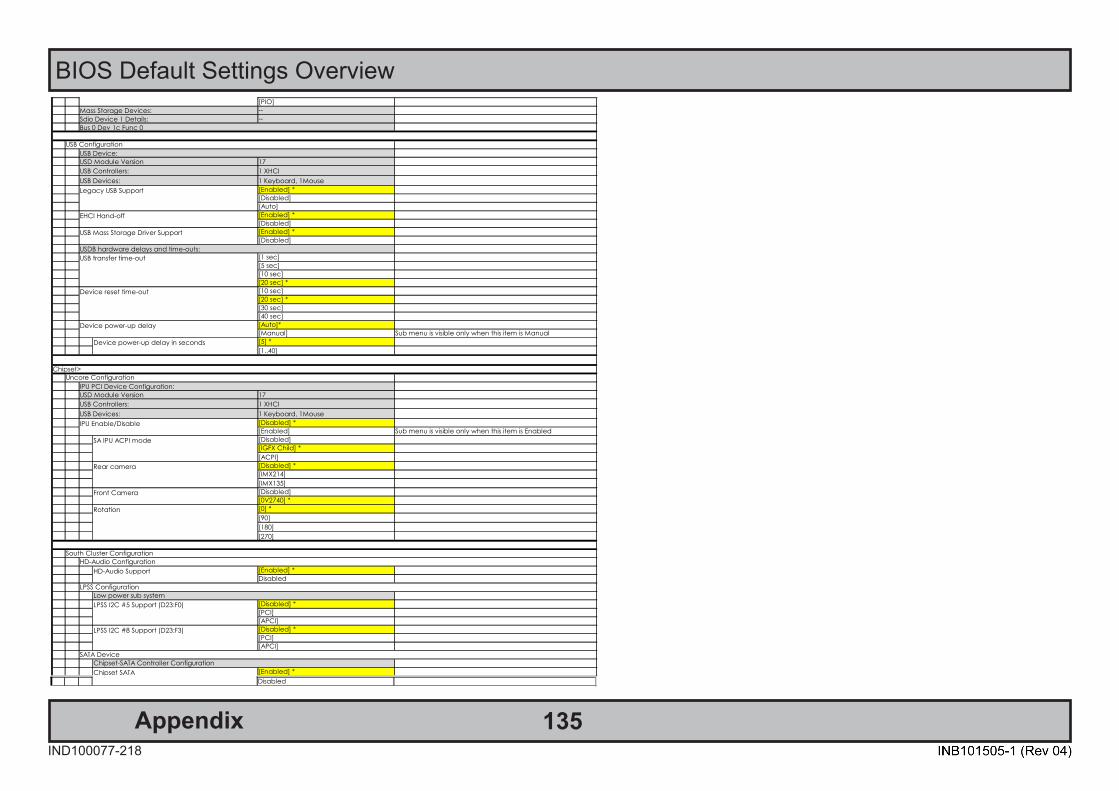
135AppendixIND100077-218
BIOS Default Settings OverviewSDIO Access Mode
[PIO]
Mass Storage Devices: --
Sdio Device 1 Details: --
Bus 0 Dev 1c Func 0
USB Configuration
USB Device:
USD Module Version 17
USB Controllers: 1 XHCI
USB Devices: 1 Keyboard, 1Mouse
Legacy USB Support [Enabled] *
[Disabled]
[Auto]
EHCI Hand-off [Enabled] *
[Disabled]
USB Mass Storage Driver Support [Enabled] *
[Disabled]
USDB hardware delays and time-outs:
USB transfer time-out [1 sec]
[5 sec]
[10 sec]
[20 sec] *
Device reset time-out [10 sec]
[20 sec] *
[30 sec]
[40 sec]
Device power-up delay [Auto]*
[Manual] Sub menu is visible only when this item is Manual
Device power-up delay in seconds [5] *
[1..40]
Chipset>
Uncore Configuration
IPU PCI Device Configuration:
USD Module Version 17
USB Controllers: 1 XHCI
USB Devices: 1 Keyboard, 1Mouse
IPU Enable/Disable [Disabled] *
[Enabled] Sub menu is visible only when this item is Enabled
SA IPU ACPI mode [Disabled]
[IGFX Child] *
[ACPI]
Rear camera [Disabled] *
[IMX214]
[IMX135]
Front Camera [Disabled]
[0V2740] *
Rotation [0] *
[90]
[180]
[270]
South Cluster Configuration
HD-Audio Configuration
HD-Audio Support [Enabled] *
Disabled
LPSS Configuration
Low power sub system
LPSS I2C #5 Support (D23:F0) [Disabled] *
[PCI]
[APCI]
LPSS I2C #8 Support (D23:F3) [Disabled] *
[PCI]
[APCI]
SATA Device
Chipset-SATA Controller Configuration
Chipset SATA [Enabled] *Chipset SATADisabled
SATA Mode Selection [AHCI] *
SATA Port 0 xxx
SATA Port 1 xxx
USB Configuration
XHCI Pre-Boot Driver [Enable]
[Disable] *
XHCI Mode [Enable] *
[Disable]
USB VBUS [Off]
[ON] *
USB HSIC1 Support [Enable]
[Disable] *
USB SSIC1 Support [Enable]
[Disable] *
USB Port Disable Override [Disabled] *
[Enabled] Sub menu is visible only when this item is Enabled
USB Port #0 [Disable]
[Enable] *
USB Port #1 [Disable]
[Enable] *
USB Port #2 [Disable]
[Enable] *
USB Port #3 [Disable]
[Enable] *
USB Port #4 [Disable]
[Enable] *
USB Port #5 [Disable]
[Enable] *
USB Port #6 [Disable]
[Enable] *
USB Port #7 [Disable]
[Enable] *
USB 3 Port #0 [Disable]
[Enable] *
USB 3 Port #1 [Disable]
[Enable] *
USB 3 Port #2 [Disable]
[Enable] *
USB 3 Port #3 [Disable]
[Enable] *
USB 3 Port #4 [Disable]
[Enable] *
USB 3 Port #5 [Disable]
[Enable] *
XDCI Support [Disabled] *
[PCI Mode]
XHCI Disable Compliance Mode [FALSE] *
[TRUE]
Security>
Setup Administrator Password --
User Password --
Secure Boot
System Mode User
Secure boot Not active
Vendor Keys Active
Attempt Secure Boot [Disabled] *
Password DescriptionIF ONLY the administrator's password is set,then this only limits access to Setup and is only asked for when entering Setup.IF ONLY the User's password is set, then this is a power on password and must be entered to boot or enter Setup. In Setup the User will have Administrator rights.the password length must be in the following range:Minimum length 3Maximum length 20
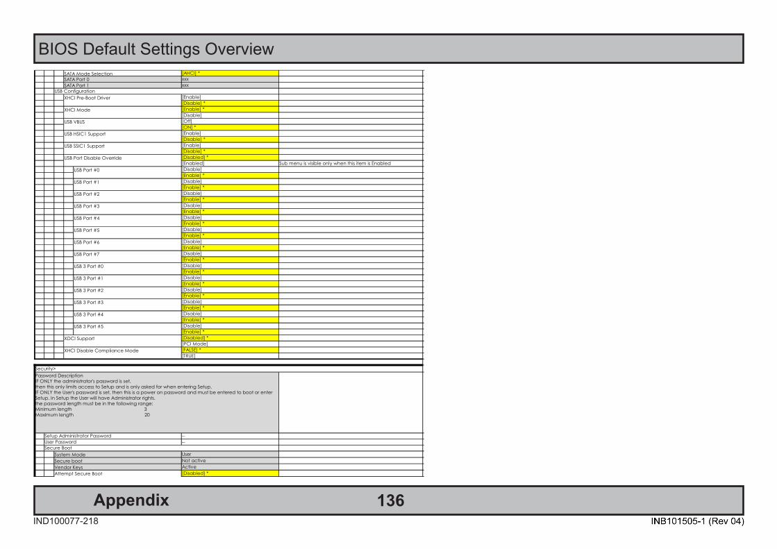
136AppendixIND100077-218
BIOS Default Settings OverviewChipset SATA
Disabled
SATA Mode Selection [AHCI] *
SATA Port 0 xxx
SATA Port 1 xxx
USB Configuration
XHCI Pre-Boot Driver [Enable]
[Disable] *
XHCI Mode [Enable] *
[Disable]
USB VBUS [Off]
[ON] *
USB HSIC1 Support [Enable]
[Disable] *
USB SSIC1 Support [Enable]
[Disable] *
USB Port Disable Override [Disabled] *
[Enabled] Sub menu is visible only when this item is Enabled
USB Port #0 [Disable]
[Enable] *
USB Port #1 [Disable]
[Enable] *
USB Port #2 [Disable]
[Enable] *
USB Port #3 [Disable]
[Enable] *
USB Port #4 [Disable]
[Enable] *
USB Port #5 [Disable]
[Enable] *
USB Port #6 [Disable]
[Enable] *
USB Port #7 [Disable]
[Enable] *
USB 3 Port #0 [Disable]
[Enable] *
USB 3 Port #1 [Disable]
[Enable] *
USB 3 Port #2 [Disable]
[Enable] *
USB 3 Port #3 [Disable]
[Enable] *
USB 3 Port #4 [Disable]
[Enable] *
USB 3 Port #5 [Disable]
[Enable] *
XDCI Support [Disabled] *
[PCI Mode]
XHCI Disable Compliance Mode [FALSE] *
[TRUE]
Security>
Setup Administrator Password --
User Password --
Secure Boot
System Mode User
Secure boot Not active
Vendor Keys Active
Attempt Secure Boot [Disabled] *
Password DescriptionIF ONLY the administrator's password is set,then this only limits access to Setup and is only asked for when entering Setup.IF ONLY the User's password is set, then this is a power on password and must be entered to boot or enter Setup. In Setup the User will have Administrator rights.the password length must be in the following range:Minimum length 3Maximum length 20
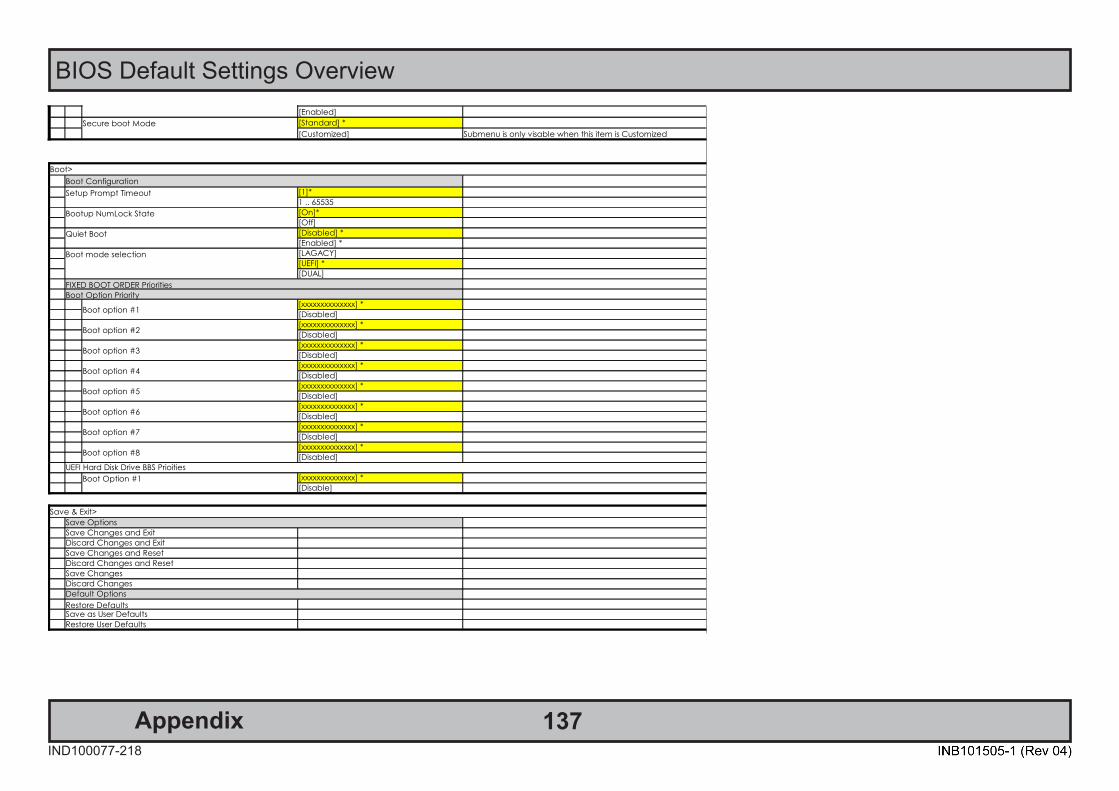
137AppendixIND100077-218
BIOS Default Settings OverviewAttempt Secure Boot
[Enabled]
Secure boot Mode [Standard] *
[Customized] Submenu is only visable when this item is Customized
Boot>
Boot Configuration
Setup Prompt Timeout [1]*
1 .. 65535
Bootup NumLock State [On]*
[Off]
Quiet Boot [Disabled] *
[Enabled] *
Boot mode selection [LAGACY]
[UEFI] *
[DUAL]
FIXED BOOT ORDER Priorities
Boot Option Priority
Boot option #1[xxxxxxxxxxxxxx] *
[Disabled]
Boot option #2[xxxxxxxxxxxxxx] *
[Disabled]
Boot option #3[xxxxxxxxxxxxxx] *
[Disabled]
Boot option #4[xxxxxxxxxxxxxx] *
[Disabled]
Boot option #5[xxxxxxxxxxxxxx] *
[Disabled]
Boot option #6[xxxxxxxxxxxxxx] *
[Disabled]
Boot option #7[xxxxxxxxxxxxxx] *
[Disabled]
Boot option #8[xxxxxxxxxxxxxx] *
[Disabled]
UEFI Hard Disk Drive BBS Prioities
Boot Option #1 [xxxxxxxxxxxxxx] *
[Disable]
Save & Exit>
Save Options
Save Changes and Exit
Discard Changes and Exit
Save Changes and Reset
Discard Changes and Reset
Save Changes
Discard Changes
Default Options
Restore DefaultsSave as User Defaults
Restore User Defaults
2. Default loadings
3. Record of modified (this document)
End of file.

138AppendixIND100077-275
WatchDog Timer function
WatchDog functions provided by Hatteland Technology:
If you are not familiar with the SCOM protocol, please review the Hatteland Technology's Serial Remote ControlInterface (SCOM) protocol document can be downloaded from:https://www.hattelandtechnology.com/hubfs/pdfget/inb100018-7.htm
Suitable commands:"WDF" - Software Watchdog Feed"WDC" - Software Watchdog Configuration
WatchDog functions provided by Third-Party:
The following link provides documentation, SDK, Code Examples and tools to access the unit's WatchDog function:Please visit third-party link: http://www.fintek.com.tw/index.php/supports/sw-developkitdl
7/27/2021
Fintek
The information contained herein is the exclusive proprietary information of Feature Integration Technology Inc., is provided for customer’s internal use only, and shall not be disclosed, distributed to any third party or reproduced in whole or in part by any third party without the prior written permission of Feature Integration Technology Inc. 本資料為精拓科技股份有限公司之智慧財產權,僅供客戶內部使用;非經精拓科技股份有限公司事前書面授權許可,不得透露、散佈予任何第三人或使任何第三人使用本資料之全部或一部,或將之複印、複製或
轉變成其它任何形式使用。
Fintek
Software Development Kit
Windows Software Programming Guide
v1.18 July 27, 2021
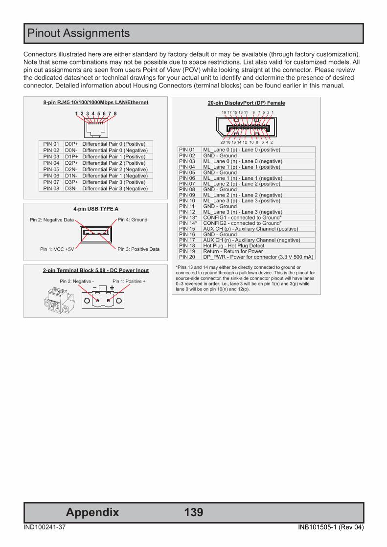
139IND100241-37
Appendix
Pinout Assignments
8-pin RJ45 10/100/1000Mbps LAN/Ethernet
1 2 3 4 5 6 7 8
PIN 01 D0P+ Diff erential Pair 0 (Positive)PIN 02 D0N- Diff erential Pair 0 (Negative)PIN 03 D1P+ Diff erential Pair 1 (Positive)PIN 04 D2P+ Diff erential Pair 2 (Positive)PIN 05 D2N- Diff erential Pair 2 (Negative)PIN 06 D1N- Diff erential Pair 1 (Negative)PIN 07 D3P+ Diff erential Pair 3 (Positive)PIN 08 D3N- Diff erential Pair 3 (Negative)
Connectors illustrated here are either standard by factory default or may be available (through factory customization).Note that some combinations may not be possible due to space restrictions. List also valid for customized models. All pin out assignments are seen from users Point of View (POV) while looking straight at the connector. Please review the dedicated datasheet or technical drawings for your actual unit to identify and determine the presence of desired connector. Detailed information about Housing Connectors (terminal blocks) can be found earlier in this manual.
4-pin USB TYPE A
Pin 2: Negative Data
Pin 1: VCC +5V Pin 3: Positive Data
Pin 4: Ground
2-pin Terminal Block 5.08 - DC Power Input
Pin 2: Negative - Pin 1: Positive +
20-pin DisplayPort (DP) Female
20 18 16 14 12 10 8 6 4 2
19 17 15 13 11 9 7 5 3 1
PIN 01 ML_Lane 0 (p) - Lane 0 (positive)PIN 02 GND - GroundPIN 03 ML_Lane 0 (n) - Lane 0 (negative)PIN 04 ML_Lane 1 (p) - Lane 1 (positive)PIN 05 GND - GroundPIN 06 ML_Lane 1 (n) - Lane 1 (negative)PIN 07 ML_Lane 2 (p) - Lane 2 (positive)PIN 08 GND - GroundPIN 09 ML_Lane 2 (n) - Lane 2 (negative)PIN 10 ML_Lane 3 (p) - Lane 3 (positive)PIN 11 GND - GroundPIN 12 ML_Lane 3 (n) - Lane 3 (negative)PIN 13* CONFIG1 - connected to Ground*PIN 14* CONFIG2 - connected to Ground*PIN 15 AUX CH (p) - Auxiliary Channel (positive)PIN 16 GND - GroundPIN 17 AUX CH (n) - Auxiliary Channel (negative)PIN 18 Hot Plug - Hot Plug DetectPIN 19 Return - Return for PowerPIN 20 DP_PWR - Power for connector (3.3 V 500 mA)
*Pins 13 and 14 may either be directly connected to ground or connected to ground through a pulldown device. This is the pinout for source-side connector, the sink-side connector pinout will have lanes 0–3 reversed in order; i.e., lane 3 will be on pin 1(n) and 3(p) while lane 0 will be on pin 10(n) and 12(p).
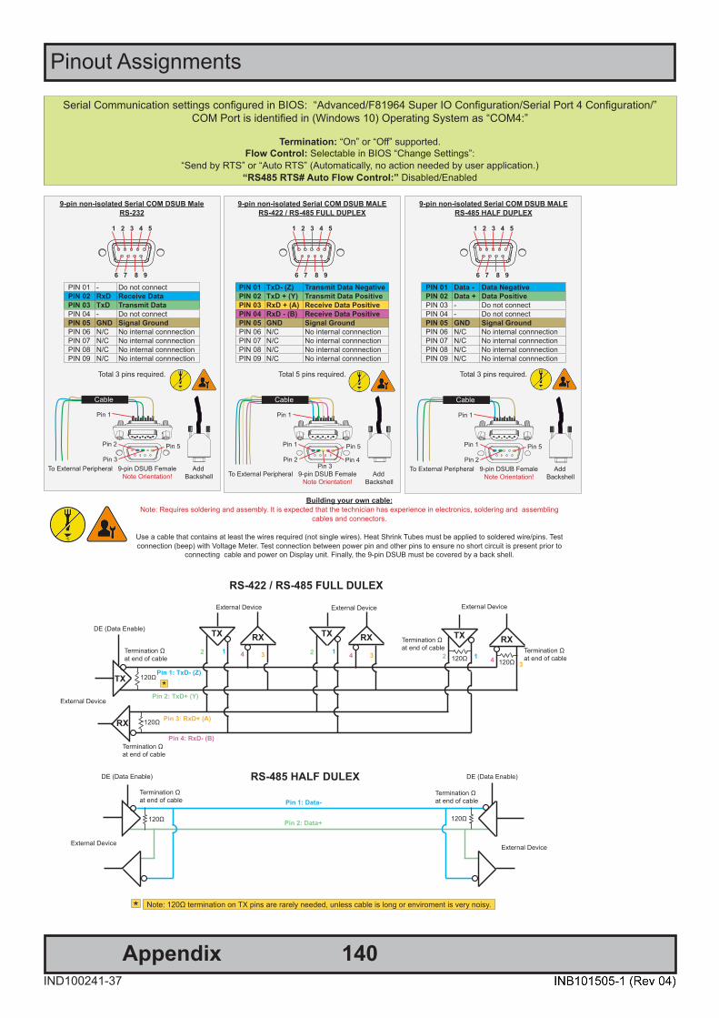
Pinout Assignments
140IND100241-37
Appendix
Serial Communication settings configured in BIOS: “Advanced/F81964 Super IO Configuration/Serial Port 4 Configuration/”COM Port is identified in (Windows 10) Operating System as “COM4:”
Termination: “On” or “Off” supported.Flow Control: Selectable in BIOS “Change Settings”:
“Send by RTS” or “Auto RTS” (Automatically, no action needed by user application.) “RS485 RTS# Auto Flow Control:” Disabled/Enabled
9-pin non-isolated Serial COM DSUB MaleRS-232
1 2 3 4 5
6 7 8 9
PIN 01 - Do not connectPIN 02 RxD Receive Data PIN 03 TxD Transmit Data PIN 04 - Do not connectPIN 05 GND Signal GroundPIN 06 N/C No internal connnectionPIN 07 N/C No internal connnectionPIN 08 N/C No internal connnectionPIN 09 N/C No internal connnection
Total 3 pins required.
Pin 1
Pin 3
Pin 5Pin 2
To External Peripheral 9-pin DSUB Female Add Note Orientation! Backshell
Cable
9-pin non-isolated Serial COM DSUB MALERS-485 HALF DUPLEX
1 2 3 4 5
6 7 8 9
PIN 01 Data - Data NegativePIN 02 Data + Data PositivePIN 03 - Do not connectPIN 04 - Do not connectPIN 05 GND Signal GroundPIN 06 N/C No internal connnectionPIN 07 N/C No internal connnectionPIN 08 N/C No internal connnectionPIN 09 N/C No internal connnection
Total 3 pins required.
Pin 1
Pin 2
Pin 5Pin 1
To External Peripheral 9-pin DSUB Female Add Note Orientation! Backshell
Cable
9-pin non-isolated Serial COM DSUB MALERS-422 / RS-485 FULL DUPLEX
1 2 3 4 5
6 7 8 9
PIN 01 TxD- (Z) Transmit Data NegativePIN 02 TxD + (Y) Transmit Data PositivePIN 03 RxD + (A) Receive Data PositivePIN 04 RxD - (B) Receive Data PositivePIN 05 GND Signal GroundPIN 06 N/C No internal connnectionPIN 07 N/C No internal connnectionPIN 08 N/C No internal connnectionPIN 09 N/C No internal connnection
Total 5 pins required.
Pin 1
Pin 2
Pin 5Pin 1
To External Peripheral 9-pin DSUB Female Add Note Orientation! Backshell
Pin 3Pin 4
Cable
Building your own cable:Note: Requires soldering and assembly. It is expected that the technician has experience in electronics, soldering and assembling
cables and connectors.
Use a cable that contains at least the wires required (not single wires). Heat Shrink Tubes must be applied to soldered wire/pins. Test connection (beep) with Voltage Meter. Test connection between power pin and other pins to ensure no short circuit is present prior to
connecting cable and power on Display unit. Finally, the 9-pin DSUB must be covered by a back shell.
RS-422 / RS-485 FULL DULEX
120Ω
DE (Data Enable)
External Device
Termination Ω at end of cable
External Device
TX
TX RX
RX 120Ω
Termination Ω at end of cable
120Ω 120Ω
Termination Ω at end of cable
Termination Ω at end of cable
TX
External Device
TX
External Device
RX RX
Pin 1: TxD- (Z)
Pin 2: TxD+ (Y)
Pin 3: RxD+ (A)
Pin 4: RxD- (B)
1 112 2 24 4 4
3 33
*
RS-485 HALF DULEX
120Ω
Pin 1: Data-
Pin 2: Data+
External Device
120Ω
Termination Ω at end of cable
Termination Ω at end of cable
External Device
DE (Data Enable)DE (Data Enable)
Note: 120Ω termination on TX pins are rarely needed, unless cable is long or enviroment is very noisy.*

Pinout Assignments
141IND100241-37
Appendix
10+10 pin RS-422 / RS-485 NMEA ModuleType Number “PCA200828-1 / PCA100293-1”
6 7 8 9 101 2 3 4 5
6 7 8 9 101 2 3 4 5
PIN 01 TxD- Transmit Data NegativePIN 02 TxD+ Transmit Data PositivePIN 03 GND Isolated GroundPIN 04 RxD- Receive Data NegativePIN 05 RxD+ Receive Data PositivePIN 06 TxD- Transmit Data NegativePIN 07 TxD+ Transmit Data PositivePIN 08 GND Isolated GroundPIN 09 RxD- Receive Data NegativePIN 10 RxD+ Receive Data Positive
RS-485 Half Duplex (2-wire) Confi guration:Connect TX and RX pair-wise:
TX- to RX-, TX+ to RX+.
*Note: The jumper for “force of transmitter (Forced TX(y)” is open by factory default. For
some custom models this jumper is preset to closed (active), in that case unit has to be opened and jumper set to open to allow Half
Duplex mode.
COM Module RS-232 - 2 x ports, 9-pin DSUB MaleType Number “PCA100309-1”
A B
1 2 3 4 5
6 7 8 9 PIN 01 DCD Data Carrier DetectPIN 02 RxD Receive DataPIN 03 TxD Transmit DataPIN 04 DTR Data Terminal ReadyPIN 05 GND Signal GroundPIN 06 DSR Data Set ReadyPIN 07 RTS Request To SendPIN 08 CTS Clear To SendPIN 09 RI Ring Indicator
8-pin RJ-45 10/100Mbps LAN/EthernetPCA100298-1 / HT 00274 OPT-A1
1 2 3 4 5 6 7 8
Pin 01 - TDP Transmit Diff erential Pair (Positive)Pin 02 - TDN Transmit Diff erential Pair (Negative)Pin 03 - RDP Receive Diff erential Pair (Positive)Pin 04 - NC Not ConnectedPin 05 - NC Not ConnectedPin 06 - RDN Receive Diff erential Pair (Negative)Pin 07 - NC Not ConnectedPin 08 - NC Not Connected
10+10 pin Isolated Digital Input/Output ModuleType Number “PCA100297-1”
Module A Module B
Module A Module BA1 External Power + A1 IN+[0]A2 N/C (Not Connected) A2 IN-[0]B1 External Power - (GND1) B1 IN+[1]B2 N/C (Not Connected) B2 IN-[1]O1 HS[0] O1 N/CC1 HS[1] C1 IN+[2]C2 N/C (Not Connected) C2 IN-[2]D1 HS[2] D1 IN+[3]D2 N/C (Not Connected) D2 IN-[3]O2 HS[3] O2 N/C
9-pin Amplifi ed Mono/Stereo Audio Out, DSUB FemaleType Number “HT 00235 OPT-A1”
5 4 3 2 1
9 8 7 6
PIN 01 LAUDR Left Audio Return*PIN 02 LAUD Left Audio*PIN 03 RAUDR Right Audio ReturnPIN 04 RAUD Right AudioPIN 05 N/C No internal connectionPIN 06 N/C No internal connectionPIN 07 N/C No internal connectionPIN 08 N/C No internal connectionPIN 09 N/C No internal connection
*For Mono: connect pin 01 and 02 only
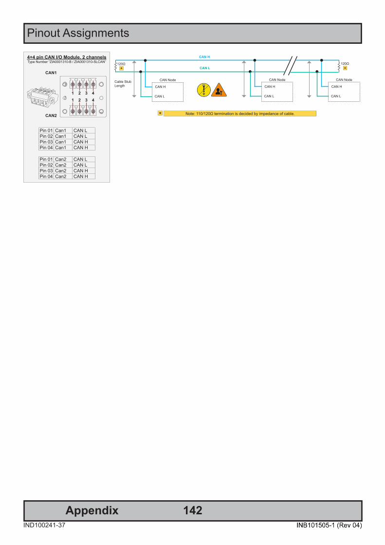
Pinout Assignments
142IND100241-37
Appendix
4+4 pin CAN I/O Module, 2 channelsType Number “ZIA0001310-B / ZIA0001310-SLCAN”
CAN1
CAN2
1 2 3 41 2 3 4
Pin 01 Can1 CAN LPin 02 Can1 CAN LPin 03 Can1 CAN HPin 04 Can1 CAN H
Pin 01 Can2 CAN LPin 02 Can2 CAN LPin 03 Can2 CAN HPin 04 Can2 CAN H
CAN Node
CAN H
CAN L*
Note: 110/120Ω termination is decided by impedance of cable.*
120Ω
*120Ω
Cable StubLength CAN H
CAN L
CAN Node
CAN H
CAN L
CAN Node
CAN H
CAN L

143IND100078-80
IEC62368 policy for Hatteland Technology products
IntroductionAccording to the requirements of EN 62368-1:2014.
The tables below refers to the policies for opening, servicing and installation of the unit(s) referred to in this manual. This equipment is designed to be used as a fixed installation and to be sold through special sales channels for professional use.
Based on requirements EN 62368-1:2014 and IEC 62368-1:2018
Defenition DescriptionOrdinary person/Sailor/End-User
Ordinary person is the term applied to all persons other than instructed persons and skilled persons. Ordinary persons include not only users of the equipment, but also all persons who may have access to the equipment or who may be in the vicinity of the equipment. Under normal operating conditions or abnormal operating conditions, ordinary persons should not be exposed to parts comprising energy sources capable of causing pain or injury. Under a single fault condition, ordinary persons should not be exposed to parts comprising energy sources capable of causing injury.
Instructed person Instructed person is a term applied to persons who have been instructed and trained by a skilled person, or who are supervised by a skilled person, to identify energy sources that may cause pain and to take precautions to avoid unintentional contact with or exposure to those energy sources. Under normal operating conditions, abnormal operating conditions or single fault conditions, instructed persons should not be exposed to parts comprising energy sources capable of causing injury.
Skilled person Skilled person is a term applied to persons who have training or experience in the equipment technology, particularly in knowing the various energies and energy magnitudes used in the equipment. Skilled persons are expected to use their training and experience to recognize energy sources capable of causing pain or injury and to take action for protection from injury from those energies. Skilled persons should also be protected against unintentional contact or exposure to energy sources capable of causing injury.

144
IEC62368 policy for Hatteland Technology products
IND100078-80
Authority DescriptionChildren This equipment is not suitable for use in locations where children are likely to be present.
Ordinary person/Sailor/End-User
Not allowed to open unit. Not allowed to install the unit. Not allowed to terminate/connect cables to the unit.
Instructed person Allowed to open hatches/latches which does not require tools, such as Disktrays. Allowed to open "battery-hatch" to change the battery even if tools are required.Allowed to install the unit.Allowed to terminate/connect cables to the unit indoors.
Skilled person Allowed to open and disassemble the unit.
Allowed to install the unit.Allowed to terminate/connect cables to the unit indoors and outdoors.Allowed to terminate/connect earth/ground wire. Note: Be aware that additional definition for “skilled person” may apply, country dependent.
Conditions DescriptionAC power net Class Class 1.
Pollution degree 2.Over voltage category 2.
Transient requirement External circuits are considered to be installed wholly within the same building structure.Battery Obligated to use battery specified for the product.Altitude Products are designed for a max operating altitude of 2000m.
Installation DescriptionMounting brackets Only bracket defined/specified for the unit is allowed.
AC power cord When installed it shall be possible to disconnect the unit from the AC power neti.e. possible to reach AC connecter.
Transient requirement External circuits are considered to be installed wholly within the same building structure.Earthing Obligated to use defined earthing material/method specified for the unit.
Minimum protective bonding conductor size of copper conductors:Wire: Minimum 1,5mm2 but Hatteland Technology recommends 2,5mm2 (AWG12)marked yellow/green.
Outdoor Units with IP66/67-rated fronts can be used in outside environments, provided that the console they are fitted in fulfil certain requirements.
- There must be a fully water/dustproof seal between the IP66 front and the console. - Dust/water ingress protection of console. (Unit/product is rated for pollution degree 2). - Humidity/condensation control in console. - Thermal management in console (so units can operate within rated temperature range).
Units with IP20/IP22 shall not be used outdoor.Outdoor Installation Appropriate RCD with ground current rating of 20mA or less shall be used.

145AppendixIND100077-185
Basic Trouble-shooting
GENERAL ISSUES FOR TFT PANEL BASED PRODUCTSNote: Applies for a range of various products. This is only meant as a general guide.
NO PICTURE / LED BEHAVIOUR:If there is no light at all in the LED at the FRONT, check power cables. If the LED in front is green, then check if the brightness is set/adjusted to max brightness. Lack of image is most likely to be caused by incorrect connection, lack of power or wrong BIOS settings.
SCROLLING / UNSTABLE IMAGE:Signal cable may not be completely connected to computer or TFT display. Check the pin assignments and signaltimings of the display and your video card with respect to recommended timing and pin assignments. Make sure that the video card is compatible and that it is properly seated / installed on the computer.
DISPLAY AREA IS NOT CENTERED / SIZED CORRECTLYMake sure that a supported video mode has been selected on the display, or on the video card / system. If it isimpossible to position the image correctly, i.e. the image adjustment controls will not move the image far enough, then test it again using another graphics card for the PC system. This situation may occur with a custom graphics card that is not close to standard timings or if something is in the graphics line that may be affecting the signal, such as a signal splitter (please note that normally a signal splitter will not have any adverse effect). If it is impossible to change to the correct resolution/color depth, check if you have the right graphics driver installed in your system.
IMAGE APPEARANCE:A faulty TFT panel can have black lines, pixel errors, failed sections, flickering or flashing image. Incorrect graphic card refresh rate, resolution or interlaced mode will probably cause the image to be the wrong size, it may scroll, flicker badly or possibly even no image is present. Sparkling on the display may be a faulty TFT panel signal cable, and it needs service attention.
VGA Signal Only: Horizontal interference can usually be corrected by adjusting the PHASE (OSD menu). Vertical interference can usually be corrected by adjusting the FREQUENCY (OSD menu).
DEW CONDENSATION BEHIND GLASS:Note that this problem will not occur on bonded products. For non-bonded products, do the following:Power on the TFT product and set brightness to 100%. Turn off any automatic screensavers on PC or similar. During minutes the dew will be gone. To speed up the process, use a fan heater for a reasonable time. Do not overheat the unit.

IND100237-1
Declaration of ConformityWe, manufacturer, Hatteland Technology AS, Eikeskogvegen 52, N-5570 Aksdal, Norway
declare under our sole responsibility that the JH MMD, JH MMC, JH STD, JH MIL, HM NMD, HM MIL, HM CMD, HT STD, HD MMD, HD MVD, HM MMD, HM XRD, HM RMD, HT MMC, HD MMC, HT/HM (computers) and HN G (Network Switches) product ranges is in
conformity with the following standards in accordance with the EMC Directive.
Low Voltage Directive 2014/35/EU EN 62368-1:2014;A11:2017
EMC Directive 2014/30/EU EN 55032:2015EN 55035:2017
EN 55024:2010+A1:2015EN IEC 63000:2018
Signature:........................................................Frode Grindheim
Vice President Product ManagementAksdal, Norway
CE MARK FIRST AFFIXED DATE (11 March 2010)
Signature:........................................................Arne Kristiansen
Site Manager - Test & Commission Division Oslo, Norway
Declaration of ConformityWe, manufacturer, Hatteland Technology AS, Eikeskogvegen 52, N-5570 Aksdal, Norway
declare under our sole responsibility that the products listed below comply withFCC 47 CFR Part 15, Subpart B, Class A:
JH MMD, JH MMC, JH STD, JH MIL, HM NMD, HM MIL, HM CMD, HT STD, HD MMD, HD MVD, HM MMD, HM XRD,HM RMD, HT MMC, HD MMC, HT/HM (computers) and HN G (Network Switches) product ranges
Note: This equipment has been tested and found to comply with the limits for a Class A digital device, pursuant to part 15 of the FCC Rules.These limits are designed to provide reasonable protection against harmful interference when the equipment is operated in a commercial
environment. This equipment generates, uses, and can radiate radio frequency energy and, if not installed and used in accordance with theinstruction manual, may cause harmful interference to radio communications. Operation of this equipment in a residential area is likely to
cause harmful interference in which case the user will be required to correct the interference at his own expense.
Signature:........................................................Frode Grindheim
Vice President Product ManagementAksdal, Norway
FCC MARK FIRST AFFIXED DATE (16 February 2012)
Signature:........................................................Arne Kristiansen
Site Manager - Test & Commission Division Oslo, Norway
Declaration of ConformityWe, manufacturer, Hatteland Technology AS, Eikeskogvegen 52, N-5570 Aksdal, Norway
declare under our sole responsibility that the JH MMD, JH MMC, JH STD, JH MIL, HM NMD, HM MIL, HM CMD, HT STD,HD MMD, HD MVD, HM MMD, HM XRD, HM RMD, HT MMC, HD MMC, HT/HM (computers) and HN G (Network Switches)
product ranges is in conformity with IEC 60945 4th (EN 60945:2002) and IACS E10 (where applicable)
This document was last approved, reviewed and found valid on 06 Oct 2021 by the signed participants as stated above.
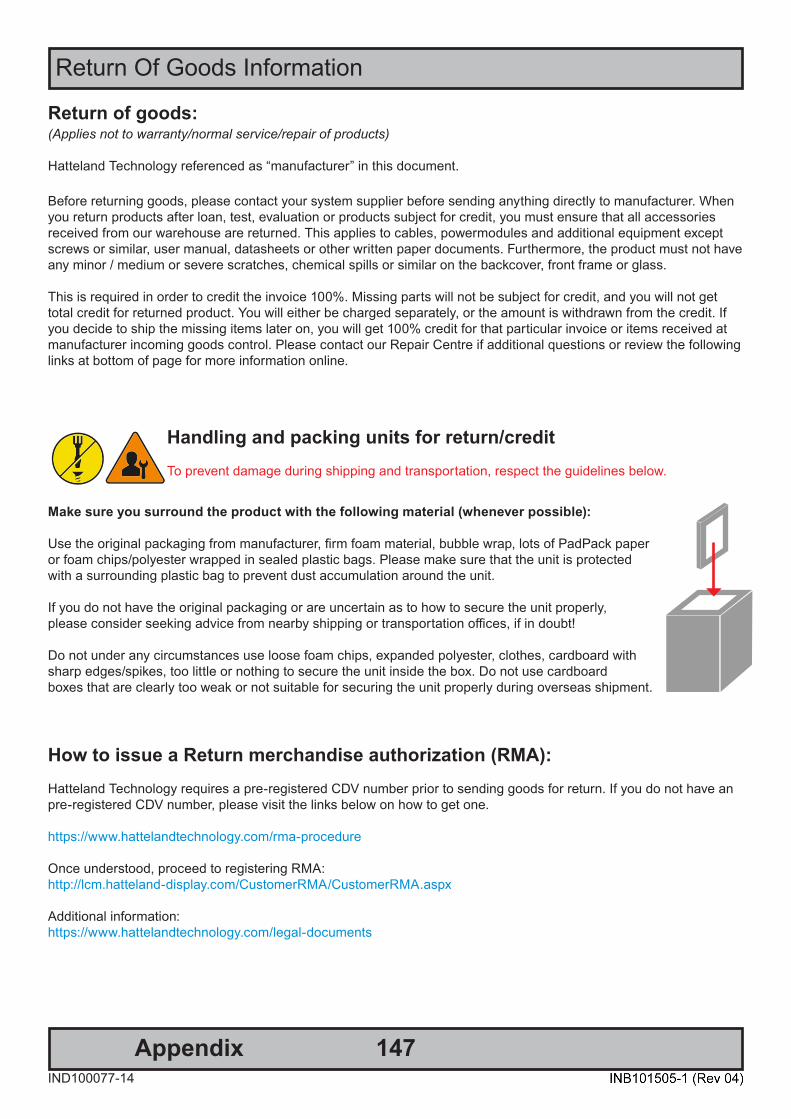
147IND100077-14
Appendix
Return of goods: (Applies not to warranty/normal service/repair of products)
Hatteland Technology referenced as “manufacturer” in this document.
Before returning goods, please contact your system supplier before sending anything directly to manufacturer. When you return products after loan, test, evaluation or products subject for credit, you must ensure that all accessories received from our warehouse are returned. This applies to cables, powermodules and additional equipment except screws or similar, user manual, datasheets or other written paper documents. Furthermore, the product must not have any minor / medium or severe scratches, chemical spills or similar on the backcover, front frame or glass.
This is required in order to credit the invoice 100%. Missing parts will not be subject for credit, and you will not gettotal credit for returned product. You will either be charged separately, or the amount is withdrawn from the credit. If you decide to ship the missing items later on, you will get 100% credit for that particular invoice or items received atmanufacturer incoming goods control. Please contact our Repair Centre if additional questions or review the following links at bottom of page for more information online.
Return Of Goods Information
Make sure you surround the product with the following material (whenever possible):
Use the original packaging from manufacturer, firm foam material, bubble wrap, lots of PadPack paper or foam chips/polyester wrapped in sealed plastic bags. Please make sure that the unit is protected with a surrounding plastic bag to prevent dust accumulation around the unit.
If you do not have the original packaging or are uncertain as to how to secure the unit properly,please consider seeking advice from nearby shipping or transportation offices, if in doubt!
Do not under any circumstances use loose foam chips, expanded polyester, clothes, cardboard with sharp edges/spikes, too little or nothing to secure the unit inside the box. Do not use cardboardboxes that are clearly too weak or not suitable for securing the unit properly during overseas shipment.
Handling and packing units for return/creditTo prevent damage during shipping and transportation, respect the guidelines below.
How to issue a Return merchandise authorization (RMA): Hatteland Technology requires a pre-registered CDV number prior to sending goods for return. If you do not have an pre-registered CDV number, please visit the links below on how to get one.
https://www.hattelandtechnology.com/rma-procedure
Once understood, proceed to registering RMA:http://lcm.hatteland-display.com/CustomerRMA/CustomerRMA.aspx
Additional information:https://www.hattelandtechnology.com/legal-documents
148IND100077-7
Appendix
General Terms and Conditions
INSTRUCTIONS FOR THE CONSIGNEE
1) CONTROLControl the goods immediately by receipt. Examine the quantity against the invoice/packinglist/shipping documents. Look for outward defects on the packing which may indicate damage on or loss of contents. Control the container and the seals for any defects.
2) SECURING EVIDENCEWhen defects on the goods have been found, evidence must be secured, and seller must be informed. Call the transporter and point out the defects. Add a description of the defects on the goods receipt, the forwarder’s copy of the way-bill or on the driving slip.
3) RESCUETry to restrict the damage and the loss. Seller will compensate expenses incurred due to reasonable security efforts in addition to damage and loss.
4) COMPLAINTImmediately write a complaint to the transporter or his agent. Immediately forward the complaint to the transporter or his agent, and hold the transporter responsible for the defects. The complaint must be sent at the latest: - for carriage by sea: within 3 days - for overland / air transportation within 7 days
5) DOCUMENTATIONFor any claims the following documentation is required and must forwarded to the company or their agent: invoice, way-bill and/or bill of landing, and/or statement of arrival, inspection document, besides a copy of the letter of complaint to the transporter.
As of January 2015, Hatteland Technology AS’ “Terms of Sales and Delivery” and “Warranty Terms” have beensubstituted by the updated ”General terms and conditions for sale of goods and performance of additional services” (the “General Terms and Conditions”).
Further, from January 2015 onward, the previous “Terms of Sales and Delivery” and “Warranty Terms”, as well as other standard terms and conditions, policies and instructions issued by Hatteland Technology AS, will be removed from the User Manuals.
Instead, the updated General Terms and Conditions and the other standard terms and conditions, policies andinstructions issued by Hatteland Technology AS will be available via our website only.
Please visit https://www.hattelandtechnology.com/legal-documents#terms-and-conditions to review the latest revision
Long Term Storage RecommendationsFor Minimum storage life for Hatteland Technology products,Storage Conditions, Periodic maintenance - test procedure, please visit: https://www.hattelandtechnology.com/hubfs/pdf/misc/ind100350-5_long_term_storage_recommendations.pdf
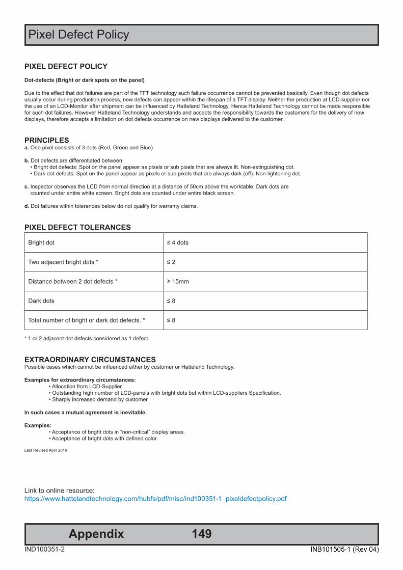
149IND100351-2
Appendix
Pixel Defect Policy
PIXEL DEFECT POLICYDot-defects (Bright or dark spots on the panel)
Due to the effect that dot failures are part of the TFT technology such failure occurrence cannot be prevented basically. Even though dot defects usually occur during production process, new defects can appear within the lifespan of a TFT display. Neither the production at LCD-supplier nor the use of an LCD-Monitor after shipment can be influenced by Hatteland Technology. Hence Hatteland Technology cannot be made responsible for such dot failures. However Hatteland Technology understands and accepts the responsibility towards the customers for the delivery of new displays, therefore accepts a limitation on dot defects occurrence on new displays delivered to the customer.
PRINCIPLESa. One pixel consists of 3 dots (Red, Green and Blue)
b. Dot defects are differentiated between: • Bright dot defects: Spot on the panel appear as pixels or sub pixels that are always lit. Non-extinguishing dot. • Dark dot defects: Spot on the panel appear as pixels or sub pixels that are always dark (off). Non-lightening dot.
c. Inspector observes the LCD from normal direction at a distance of 50cm above the worktable. Dark dots are counted under entire white screen. Bright dots are counted under entire black screen.
d. Dot failures within tolerances below do not qualify for warranty claims.
PIXEL DEFECT TOLERANCES Bright dot
≤ 4 dots
Two adjacent bright dots * ≤ 2
Distance between 2 dot defects * ≥ 15mm
Dark dots ≤ 8
Total number of bright or dark dot defects. * ≤ 8
* 1 or 2 adjacent dot defects considered as 1 defect.
EXTRAORDINARY CIRCUMSTANCESPossible cases which cannot be influenced either by customer or Hatteland Technology.
Examples for extraordinary circumstances: • Allocation from LCD-Supplier • Outstanding high number of LCD-panels with bright dots but within LCD-suppliers Specification. • Sharply increased demand by customer
In such cases a mutual agreement is inevitable.
Examples: • Acceptance of bright dots in “non-critical” display areas. • Acceptance of bright dots with defined color.
Last Revised April 2019
Link to online resource:https://www.hattelandtechnology.com/hubfs/pdf/misc/ind100351-1_pixeldefectpolicy.pdf
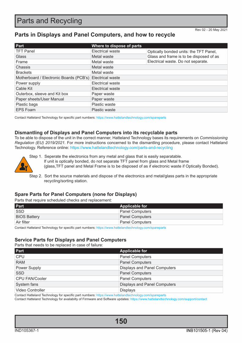
IND105367-1
Rev 02 - 20 May 2021
150
Parts and Recycling
Parts in Displays and Panel Computers, and how to recycle Part Where to dispose of partsTFT Panel Electrical waste Optically bonded units: the TFT Panel,
Glass and frame is to be disposed of as Electrical waste. Do not separate.
Glass Metal wasteFrame Metal wasteChassis Metal wasteBrackets Metal wasteMotherboard / Electronic Boards (PCB’s) Electrical wastePower supply Electrical wasteCable Kit Electrical wasteOuterbox, sleeve and Kit box Paper wastePaper sheets/User Manual Paper wastePlastic bags Plastic wasteEPS Foam Plastic waste
Contact Hatteland Technology for specific part numbers: https://www.hattelandtechnology.com/spareparts
Dismantling of Displays and Panel Computers into its recyclable partsTo be able to dispose of the unit in the correct manner, Hatteland Technology bases its requirements on Commissioning Regulation (EU) 2019/2021. For more instructions concerned to the dismantling procedure, please contact Hatteland Technology. Reference online: https://www.hattelandtechnology.com/parts-and-recycling
Step 1. Seperate the electronics from any metal and glass that is easily separatable. If unit is optically bonded, do not separate TFT panel from glass and Metal frame (glass,TFT panel and Metal Frame is to be disposed of as if electronic waste if Optically Bonded).
Step 2. Sort the source materials and dispose of the electronics and metal/glass parts in the appropriate recycling/sorting station.
Spare Parts for Panel Computers (none for Displays) Parts that require scheduled checks and replacement:Part Applicable forSSD Panel ComputersBIOS Battery Panel ComputersAir filter Panel Computers
Contact Hatteland Technology for specific part numbers: https://www.hattelandtechnology.com/spareparts
Service Parts for Displays and Panel Computers Parts that needs to be replaced in case of failure:Part Applicable forCPU Panel ComputersRAM Panel ComputersPower Supply Displays and Panel ComputersSSD Panel ComputersCPU FAN/Cooler Panel ComputersSystem fans Displays and Panel ComputersVideo Controller Displays
Contact Hatteland Technology for specific part numbers: https://www.hattelandtechnology.com/spareparts Contact Hatteland Technology for availabilty of Firmware and Software updates: https://www.hattelandtechnology.com/support/contact

151AppendixIND100077-205
Notes
General Notes:- The unit is tested according to IEC 60945 4th (EN 60945:2002), 4.4, equipment category b) “protected from the weather (formerly class B)”. - Other type approvals applies for the different products. Please see the appropriate “Specifications” page in this manual for more information.
- Use of brillance and front User Controls may inhibit visibility of information at night.
- License Terms for the installed OEM Operating System (OS) can be found in the following default factory paths: Note: This is a general listing for a varity of OS’s Hatteland Technology can factory install depending on unit. Please check specification for your unit to verify type of OS installed in order to retrieve the license terms.
Microsoft® Windows® 10 IoT Enterprise LTSC 2019: C:\Windows\System32\en-US\Licenses\_Default\EnterpriseS\license.rtf

152AppendixIND100077-24
User Notes

153AppendixIND100077-204
Rev. By Date Notes00_01 SE 21 Jun 2019 Release for internal review.
00_02 ALLSE
07 Aug 2019 Revised after internal review.
00_03 ALLSE
18 Sep 2019 Revised after internal review.
00_04 SE 18 Oct 2019 Revised after internal review.
00_05 ALLSE
17 Jan 2020 Revised after internal review.
00_06 ALLSE
12 Feb 2020 Revised after internal review.
01 ALLSE
20 Feb 2020 Pre-release for internet
02 ALLSE
20 Apr 2020to
02 Oct 2020
Revised after internal reviews and re-released to internet
03 VMJESE
06 Jul 2021 Revised after internal reviews and updated throughout entire user based on latest company profile.Updated “Recovery” section, page 119-123.Added factory option for Framegrabber/HDMI/VGA, page 35-42, 48-51, 64-66.Removed Factory Option COM Module PCA100294-1 (RS-232) throughout the entire user manual, notapplicable for these products.General updates performed and grammar and definitions improved throughout the entire user manual.Added information related to IEC62368 and Commissioning Regulation (EU) 2019/2021 throughout theentire user manual.
04 VMALLSE
24 Nov 2021 Revised after internal reviews and updated grammar throughout entire user manual.Corrected wrong definition for COM4 and COM1 (internal) ports on several related pages.Updated Technical Drawings and related documents affected by new Safety Requirements,ref: https://www.hattelandtechnology.com/product-notifications/series-e-maritime-multi-computer-chassis-updateAdded information about WatchDog SDK, page 138
Revision History

Hatteland Technology AS | www.hattelandtechnology.com | Enterprise no: NO974533146
Related Documents