PDU8000 Modular Precision PDC User Manual (FusionModule2000 V2.0) Issue 02 Date 2017-02-24 HUAWEI TECHNOLOGIES CO., LTD.

Welcome message from author
This document is posted to help you gain knowledge. Please leave a comment to let me know what you think about it! Share it to your friends and learn new things together.
Transcript
PDU8000 Modular Precision PDC
User Manual (FusionModule2000 V2.0)
Issue 02
Date 2017-02-24
HUAWEI TECHNOLOGIES CO., LTD.
Issue 02 (2017-02-24) Huawei Proprietary and Confidential
Copyright © Huawei Technologies Co., Ltd.
i
Copyright © Huawei Technologies Co., Ltd. 2017. All rights reserved.
No part of this document may be reproduced or transmitted in any form or by any means without prior
written consent of Huawei Technologies Co., Ltd.
Trademarks and Permissions
and other Huawei trademarks are trademarks of Huawei Technologies Co., Ltd.
All other trademarks and trade names mentioned in this document are the property of their respective
holders.
Notice
The purchased products, services and features are stipulated by the contract made between Huawei and
the customer. All or part of the products, services and features described in this document may not be
within the purchase scope or the usage scope. Unless otherwise specified in the contract, all statements,
information, and recommendations in this document are provided "AS IS" without warranties, guarantees or
representations of any kind, either express or implied.
The information in this document is subject to change without notice. Every effort has been made in the
preparation of this document to ensure accuracy of the contents, but all statements, information, and
recommendations in this document do not constitute a warranty of any kind, express or implied.
Huawei Technologies Co., Ltd.
Address: Huawei Industrial Base
Bantian, Longgang
Shenzhen 518129
People's Republic of China
Website: https://www.huawei.com
Email: [email protected]
PDU8000 Modular Precision PDC
User Manual (FusionModule2000 V2.0) About This Document
Issue 02 (2017-02-24) Huawei Proprietary and Confidential
Copyright © Huawei Technologies Co., Ltd.
ii
About This Document
Overview
This manual uses one single-input and one dual-input scenarios as examples. The figures are
for reference only.
Product Model
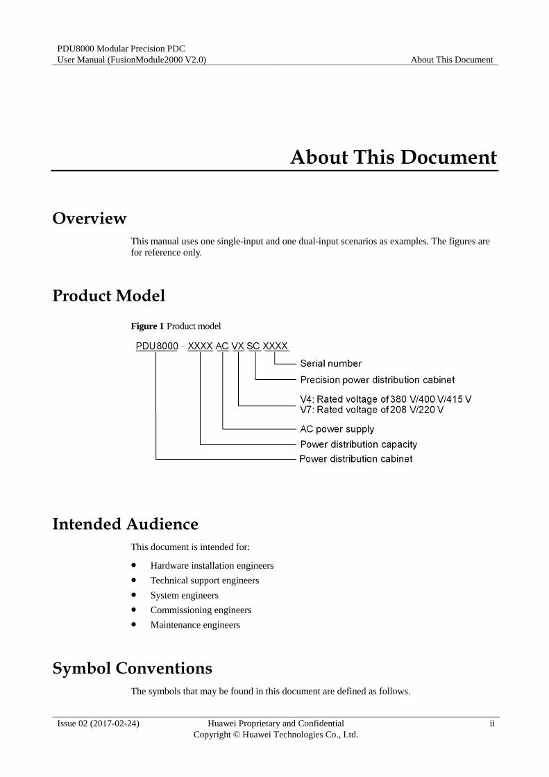
Figure 1 Product model
Intended Audience
This document is intended for:
Hardware installation engineers
Technical support engineers
System engineers
Commissioning engineers
Maintenance engineers
Symbol Conventions
The symbols that may be found in this document are defined as follows.
PDU8000 Modular Precision PDC
User Manual (FusionModule2000 V2.0) About This Document
Issue 02 (2017-02-24) Huawei Proprietary and Confidential
Copyright © Huawei Technologies Co., Ltd.
iii
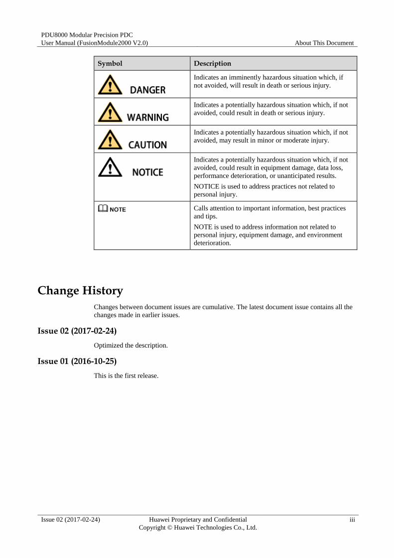
Symbol Description
Indicates an imminently hazardous situation which, if
not avoided, will result in death or serious injury.
Indicates a potentially hazardous situation which, if not
avoided, could result in death or serious injury.
Indicates a potentially hazardous situation which, if not
avoided, may result in minor or moderate injury.
Indicates a potentially hazardous situation which, if not
avoided, could result in equipment damage, data loss,
performance deterioration, or unanticipated results.
NOTICE is used to address practices not related to
personal injury.
Calls attention to important information, best practices
and tips.
NOTE is used to address information not related to
personal injury, equipment damage, and environment
deterioration.
Change History
Changes between document issues are cumulative. The latest document issue contains all the
changes made in earlier issues.
Issue 02 (2017-02-24)
Optimized the description.
Issue 01 (2016-10-25)
This is the first release.
PDU8000 Modular Precision PDC
User Manual (FusionModule2000 V2.0) Contents
Issue 02 (2017-02-24) Huawei Proprietary and Confidential
Copyright © Huawei Technologies Co., Ltd.
iv
Contents
About This Document .................................................................................................................... ii
1 User Manual Usage ....................................................................................................................... 1
2 Safety Precautions ......................................................................................................................... 2
2.1 General Safety Precautions ........................................................................................................................................... 2
2.2 Electrical Safety ............................................................................................................................................................ 3
2.3 Environmental Safety ................................................................................................................................................... 4
2.4 Mechanical Safety ........................................................................................................................................................ 4
2.5 Laying Out Cables ........................................................................................................................................................ 5
2.6 PDC Silk Screen Description ........................................................................................................................................ 5
2.7 PDC Label Description ................................................................................................................................................. 6
3 Overview ......................................................................................................................................... 7
3.1 Positioning .................................................................................................................................................................... 7
3.2 Appearance ................................................................................................................................................................... 7
3.2.1 Appearance of the Modular Precision PDC with a Single Input ................................................................................ 8
3.2.2 Appearance of the Modular Precision PDC with Dual Inputs ................................................................................... 9
3.3 Features ....................................................................................................................................................................... 11
3.4 Technical Specifications ............................................................................................................................................. 12
3.5 Modules ...................................................................................................................................................................... 13
3.5.1 Configuration Principle............................................................................................................................................ 13
3.5.2 Structural Module .................................................................................................................................................... 16
3.5.3 Power Distribution Module ..................................................................................................................................... 16
3.5.4 Monitoring Module .................................................................................................................................................. 18
3.6 Components ................................................................................................................................................................ 20
3.6.1 MDU ........................................................................................................................................................................ 20
3.6.2 Monitoring Board Module ....................................................................................................................................... 23
3.6.3 MCCB ...................................................................................................................................................................... 24
3.6.4 MCB ........................................................................................................................................................................ 24
4 Acceptance Guide ....................................................................................................................... 27
5 Installation Guide ....................................................................................................................... 30
5.1 Site Requirements ....................................................................................................................................................... 30
5.2 Installation Preparations ............................................................................................................................................. 30
PDU8000 Modular Precision PDC
User Manual (FusionModule2000 V2.0) Contents
Issue 02 (2017-02-24) Huawei Proprietary and Confidential
Copyright © Huawei Technologies Co., Ltd.
v
5.2.1 Obtaining Technical Documents .............................................................................................................................. 30
5.2.2 Obtaining Tools and Materials ................................................................................................................................. 31
5.2.3 Preparing Consumables ........................................................................................................................................... 33
5.2.4 Checking Personnel Requirements .......................................................................................................................... 33
5.2.5 Checking the Installation Environment ................................................................................................................... 34
5.3 Installing the PDC ....................................................................................................................................................... 34
5.3.1 Moving the PDC ...................................................................................................................................................... 34
5.3.2 Installing the PDC on a Concrete Floor ................................................................................................................... 37
5.3.3 Installing the PDC on an ESD Floor ........................................................................................................................ 41
5.4 Installing Cables ......................................................................................................................................................... 43
5.4.1 Cable Routing Rules ................................................................................................................................................ 43
5.4.2 Power Cable Specifications ..................................................................................................................................... 46
5.4.3 Preparing Terminals ................................................................................................................................................. 46
5.4.4 Connecting Cables ................................................................................................................................................... 49
6 Commissioning Guide ............................................................................................................... 56
6.1 Check Before Power-on Commissioning .................................................................................................................... 56
6.2 Power-On Commissioning .......................................................................................................................................... 57
7 MDU Commissioning Guide.................................................................................................... 61
7.1 UI Appearance ............................................................................................................................................................ 61
7.2 Menu Hierarchy .......................................................................................................................................................... 63
7.3 Common Functions ..................................................................................................................................................... 63
7.3.1 Historical Alarm ....................................................................................................................................................... 64
7.3.2 Branch Output 1 ....................................................................................................................................................... 65
7.3.3 Branch Output 2 ....................................................................................................................................................... 67
7.4 System Information. ................................................................................................................................................... 68
7.4.1 Running ................................................................................................................................................................... 69
7.4.1.1 Main Input 1 ......................................................................................................................................................... 70
7.4.1.2 Branch Output 1 .................................................................................................................................................... 73
7.4.1.3 Input 1 Curve ........................................................................................................................................................ 75
7.4.1.4 Main Input 2 ......................................................................................................................................................... 76
7.4.1.5 Branch Output 2 .................................................................................................................................................... 78
7.4.1.6 Input 2 Curve ........................................................................................................................................................ 80
7.4.1.7 Query Energy Yield .............................................................................................................................................. 81
7.4.2 Alarms ...................................................................................................................................................................... 82
7.4.2.1 Active Alarm ......................................................................................................................................................... 83
7.4.2.2 Historical Alarm .................................................................................................................................................... 84
7.4.2.3 Buzzer Off ............................................................................................................................................................ 85
7.4.3 Settings .................................................................................................................................................................... 87
7.4.3.1 Communication ..................................................................................................................................................... 89
7.4.3.2 System Parameters. ............................................................................................................................................... 91
7.4.3.3 Branch Param. ....................................................................................................................................................... 95
PDU8000 Modular Precision PDC
User Manual (FusionModule2000 V2.0) Contents
Issue 02 (2017-02-24) Huawei Proprietary and Confidential
Copyright © Huawei Technologies Co., Ltd.
vi
7.4.3.4 Threshold .............................................................................................................................................................. 96
7.4.4 Maintenance ............................................................................................................................................................. 99
7.4.4.1 Loading Configurations ...................................................................................................................................... 101
7.4.4.2 Downloading Configurations .............................................................................................................................. 104
7.4.4.3 Downloading Logs .............................................................................................................................................. 106
7.4.4.4 Exporting Alarms ................................................................................................................................................ 108
7.4.4.5 Exporting E-labels .............................................................................................................................................. 109
7.4.4.6 Uploading Modbus Configurations ..................................................................................................................... 111
7.4.4.7 Downloading Modbus Configurations ................................................................................................................ 113
7.4.4.8 Upgrade Software ............................................................................................................................................... 115
7.4.5 About ..................................................................................................................................................................... 119
7.5 Operating Status ........................................................................................................................................................ 120
7.6 DIP Switches............................................................................................................................................................. 121
8 Maintenance Guide .................................................................................................................. 123
8.1 O&M Precautions ..................................................................................................................................................... 123
8.2 Routine Maintenance ................................................................................................................................................ 123
8.2.1 Monthly Maintenance ............................................................................................................................................ 124
8.2.2 Quarterly Maintenance .......................................................................................................................................... 125
8.2.3 Annual Maintenance .............................................................................................................................................. 125
8.3 Alarm Reference ....................................................................................................................................................... 126
8.4 Troubleshooting ........................................................................................................................................................ 131
8.5 Parts Replacement .................................................................................................................................................... 131
8.5.1 Replacing an SPD Module ..................................................................................................................................... 131
8.5.2 Replacing an Indicator ........................................................................................................................................... 133
8.5.3 Replacing an MCB ................................................................................................................................................ 135
8.5.4 Replacing a Fuse .................................................................................................................................................... 139
8.5.5 Replacing the Monitoring Board ........................................................................................................................... 141
8.5.6 Replacing an MDU ................................................................................................................................................ 142
A Contacting Huawei Technical Support ............................................................................... 145
B Acronyms and Abbreviations ................................................................................................ 146
PDU8000 Modular Precision PDC
User Manual (FusionModule2000 V2.0) 1 User Manual Usage
Issue 02 (2017-02-24) Huawei Proprietary and Confidential
Copyright © Huawei Technologies Co., Ltd.
1
1 User Manual Usage
This chapter describes the notes for using the precision modular PDC user guide.
Before using this document, get familiar with the actual configuration and application
scenario of the modular precision PDC.
Before using this document, make available the documents delivered with each
component.
Screenshots provided in this document correspond to the monitor display module (MDU)
version V100R002C44V220B002D00 and are for reference only.
Put on necessary protective equipment such as the safety helmet and gloves before
entering the site.
Before performing an operation, ensure that the prerequisites are met. Otherwise, the
expected result may not be achieved. More seriously, equipment damage and personal
injury may occur.
Before using this document, read through and keep in mind the safety precautions and
the cautions and notes for operations.
Configuration parameters are essential to the reliable running of a system. Improper
modifications of parameters easily cause abnormal running status, or even damage to the
system.
You are not allowed to modify configuration parameters without permission when using
the modular precision PDC. If a modification is necessary, contact Huawei technical
support. Huawei shall not be responsible for any loss caused by unauthorized
configuration modification.
Operations marked as optional in the chapters, sections, or procedures can be performed
depending on the actual configuration and requirements of the modular precision PDC.

PDU8000 Modular Precision PDC
User Manual (FusionModule2000 V2.0) 2 Safety Precautions
Issue 02 (2017-02-24) Huawei Proprietary and Confidential
Copyright © Huawei Technologies Co., Ltd.
2
2 Safety Precautions
2.1 General Safety Precautions
General Safety Principles
To ensure safety of humans and the equipment, pay attention to the safety symbols on the
equipment and all the safety instructions in this document.
The "Note", "CAUTION", "WARNING", and "DANGER" statements in this document do not
represent all the safety instructions. They are only supplements to the safety instructions.
Local Safety Regulations
When operating Huawei equipment, you must follow the local laws and regulations. The
safety instructions in this document are only supplements to the local laws and regulations.
Personnel Requirements
Personnel who plan to install, operate, and maintain Huawei equipment must be thoroughly
trained, understand all necessary safety precautions, and master correct operation methods.
Only trained and qualified personnel are allowed to install, operate, and maintain the
equipment.
Only qualified professionals are allowed to remove safety facilities and check the
equipment.
Only personnel certified or authorized by Huawei are allowed to replace or change the
equipment or components (including software).
Any fault or error that might cause safety problems must be reported immediately to a
supervisor.
Grounding Requirements
Equipment to be grounded must meet the following requirements:
When installing the device, always make the ground connection first. When removing
the device, disconnect the ground cable at the end.
Do not damage the ground conductor.
Do not operate the device in the absence of a properly installed ground conductor.
PDU8000 Modular Precision PDC
User Manual (FusionModule2000 V2.0) 2 Safety Precautions
Issue 02 (2017-02-24) Huawei Proprietary and Confidential
Copyright © Huawei Technologies Co., Ltd.
3
The device (or system) must be connected permanently to the protection ground before
operation. Before operating the device, check its electrical connection to ensure that it is
securely grounded.
Human Safety Do not operate the device or cables during thunderstorms.
In the case of a thunderstorm, disconnect the AC power supply, and do not use fixed
terminals or touch the terminals or antenna connectors.
Before operating the device, put on electrostatic discharge (ESD) clothes, ESD gloves,
and an ESD wrist strap. Do not wear conductive articles such as jewelry or watches
when you operate the device.
In the case of a fire, immediately leave the building or the equipment room, and turn on
the fire alarm bell or make an emergency call. Never enter a building or equipment zone
that is on fire.
Equipment Safety The device must be fixed securely on the floor or to other immovable objects such as
walls or mounting racks before operation.
Do not block the ventilation vents while the device is operating.
Tighten the screws using tools when installing panels.
After the installation, remove packing materials from the equipment area.
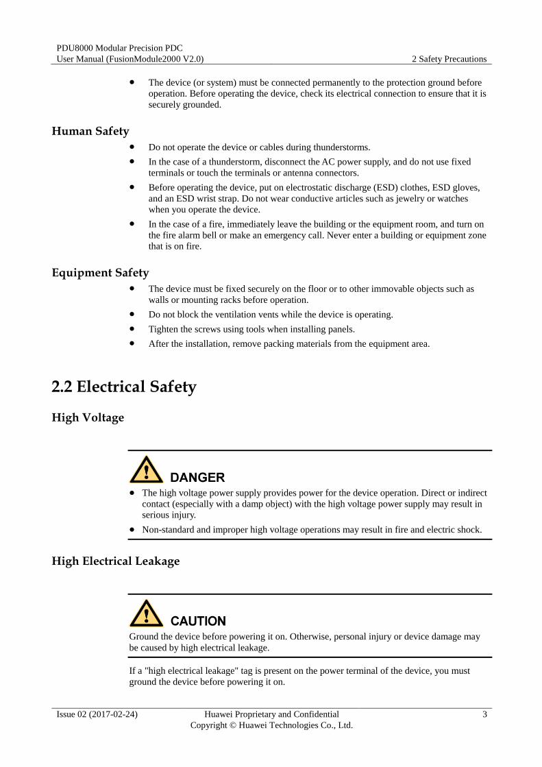
2.2 Electrical Safety
High Voltage
The high voltage power supply provides power for the device operation. Direct or indirect
contact (especially with a damp object) with the high voltage power supply may result in
serious injury.
Non-standard and improper high voltage operations may result in fire and electric shock.
High Electrical Leakage
Ground the device before powering it on. Otherwise, personal injury or device damage may
be caused by high electrical leakage.
If a "high electrical leakage" tag is present on the power terminal of the device, you must
ground the device before powering it on.
PDU8000 Modular Precision PDC
User Manual (FusionModule2000 V2.0) 2 Safety Precautions
Issue 02 (2017-02-24) Huawei Proprietary and Confidential
Copyright © Huawei Technologies Co., Ltd.
4
Power Cable
Do not install or remove power cables when the device is on. Transient contact between the
core of the power cable and the conductor may generate electric arcs or sparks, which may
cause fire or injury to human eyes.
Before installing or removing a power cable, turn off the power switch.
Before connecting a power cable, verify that the label on the power cable is correct.
Fuse
To ensure that the system runs safely, if a fuse is to be replaced, the new fuse must be of the
same type and specifications.
2.3 Environmental Safety
Do not place or operate a device in a flammable, explosive, or smoky environment.
Operating any electronic device in a flammable environment can be fatal.
2.4 Mechanical Safety
Moving Sharp Objects
Wear protective gloves when moving sharp objects.
Moving Heavy Objects
Wear protective gloves to protect hands when moving heavy objects.
PDU8000 Modular Precision PDC
User Manual (FusionModule2000 V2.0) 2 Safety Precautions
Issue 02 (2017-02-24) Huawei Proprietary and Confidential
Copyright © Huawei Technologies Co., Ltd.
5
Be careful to prevent injury when moving heavy objects.
It is recommended that tools such as a pallet truck be used to transport the heavy PDC.
2.5 Laying Out Cables
Binding Signal Cables
Signal cables must be bound separately from strong-current cables and high-voltage cables.
Laying Out Power Cables
When the temperature is very low, violent impact or vibration may damage the power cable
sheathing. To ensure safety, comply with the following requirements:
Power cables should be laid out or installed only when the temperature is higher than
0°C.
Store power cables for at least 24 hours at room temperature before laying out them if
they were previously stored at sub-0ºC.
Handle power cables with caution, especially at a low temperature. Do not drop the
power cables directly from the vehicle.
2.6 PDC Silk Screen Description
The silk screen content is in the format of route number + symbol + switch sequence number.
In the single-input scenario, the route number is omitted by default.
Table 2-1 Symbols
Symbol Name
QF Circuit breaker
FU Fuse
L Indicator or phase sequence
QFS SPD circuit breaker
FS SPD
PDU8000 Modular Precision PDC
User Manual (FusionModule2000 V2.0) 2 Safety Precautions
Issue 02 (2017-02-24) Huawei Proprietary and Confidential
Copyright © Huawei Technologies Co., Ltd.
6
Example of a PDC silk screen:
1QF1: indicates the first switch of route I.
2QF1: indicates the first switch of route II.
QF1: indicates the first switch when there is only one input.
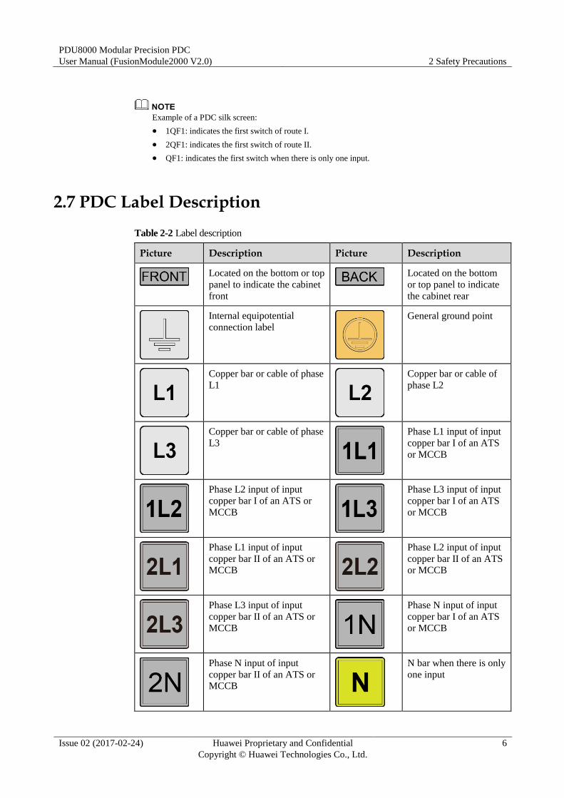
2.7 PDC Label Description
Table 2-2 Label description
Picture Description Picture Description
Located on the bottom or top
panel to indicate the cabinet
front
Located on the bottom
or top panel to indicate
the cabinet rear
Internal equipotential
connection label
General ground point
Copper bar or cable of phase
L1
Copper bar or cable of
phase L2
Copper bar or cable of phase
L3
Phase L1 input of input
copper bar I of an ATS
or MCCB
Phase L2 input of input
copper bar I of an ATS or
MCCB
Phase L3 input of input
copper bar I of an ATS
or MCCB
Phase L1 input of input
copper bar II of an ATS or
MCCB
Phase L2 input of input
copper bar II of an ATS
or MCCB
Phase L3 input of input
copper bar II of an ATS or
MCCB
Phase N input of input
copper bar I of an ATS
or MCCB
Phase N input of input
copper bar II of an ATS or
MCCB
N bar when there is only
one input
PDU8000 Modular Precision PDC
User Manual (FusionModule2000 V2.0) 3 Overview
Issue 02 (2017-02-24) Huawei Proprietary and Confidential
Copyright © Huawei Technologies Co., Ltd.
7
3 Overview
3.1 Positioning
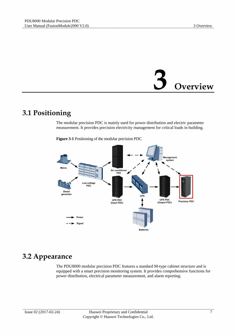
The modular precision PDC is mainly used for power distribution and electric parameter
measurement. It provides precision electricity management for critical loads in building.
Figure 3-1 Positioning of the modular precision PDC
3.2 Appearance
The PDU8000 modular precision PDC features a standard M-type cabinet structure and is
equipped with a smart precision monitoring system. It provides comprehensive functions for
power distribution, electrical parameter measurement, and alarm reporting.

PDU8000 Modular Precision PDC
User Manual (FusionModule2000 V2.0) 3 Overview
Issue 02 (2017-02-24) Huawei Proprietary and Confidential
Copyright © Huawei Technologies Co., Ltd.
8
3.2.1 Appearance of the Modular Precision PDC with a Single Input
For the internal structures, see Figure 3-2 and Figure 3-3.
Figure 3-2 Appearance
(1) Input module (2) Output module 1
(3) Output module 2 (4) Output module 3
PDU8000 Modular Precision PDC
User Manual (FusionModule2000 V2.0) 3 Overview
Issue 02 (2017-02-24) Huawei Proprietary and Confidential
Copyright © Huawei Technologies Co., Ltd.
9
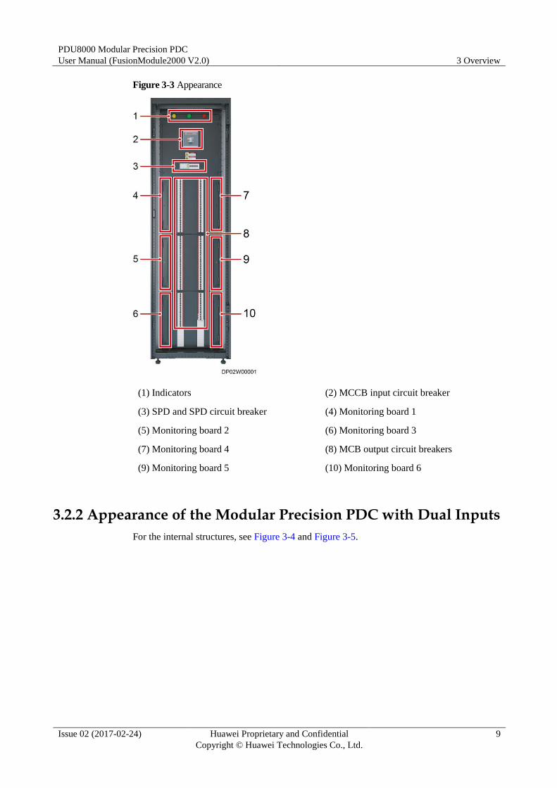
Figure 3-3 Appearance
(1) Indicators (2) MCCB input circuit breaker
(3) SPD and SPD circuit breaker (4) Monitoring board 1
(5) Monitoring board 2 (6) Monitoring board 3
(7) Monitoring board 4 (8) MCB output circuit breakers
(9) Monitoring board 5 (10) Monitoring board 6
3.2.2 Appearance of the Modular Precision PDC with Dual Inputs
For the internal structures, see Figure 3-4 and Figure 3-5.
PDU8000 Modular Precision PDC
User Manual (FusionModule2000 V2.0) 3 Overview
Issue 02 (2017-02-24) Huawei Proprietary and Confidential
Copyright © Huawei Technologies Co., Ltd.
10
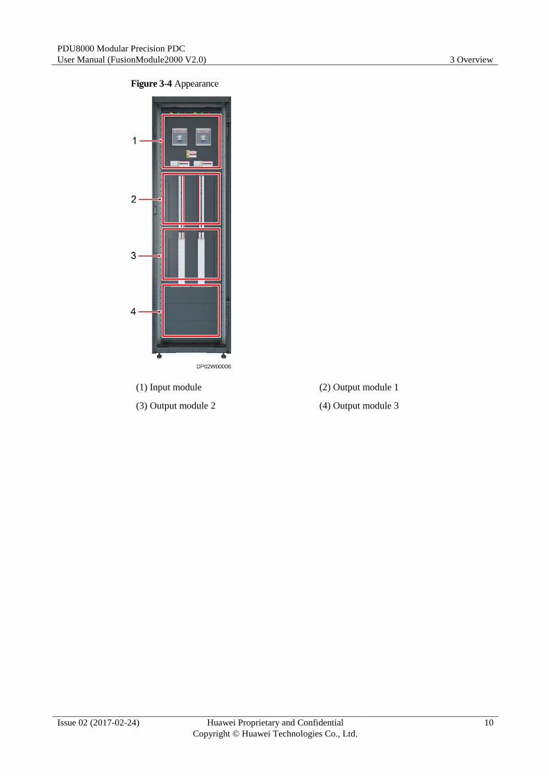
Figure 3-4 Appearance
(1) Input module (2) Output module 1
(3) Output module 2 (4) Output module 3
PDU8000 Modular Precision PDC
User Manual (FusionModule2000 V2.0) 3 Overview
Issue 02 (2017-02-24) Huawei Proprietary and Confidential
Copyright © Huawei Technologies Co., Ltd.
11
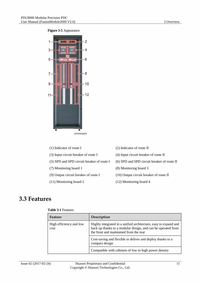
Figure 3-5 Appearance
(1) Indicator of route I (2) Indicator of route II
(3) Input circuit breaker of route I (4) Input circuit breaker of route II
(5) SPD and SPD circuit breaker of route I (6) SPD and SPD circuit breaker of route II
(7) Monitoring board 1 (8) Monitoring board 3
(9) Output circuit breaker of route I (10) Output circuit breaker of route II
(11) Monitoring board 2 (12) Monitoring board 4
3.3 Features
Table 3-1 Features
Feature Description
High efficiency and low
cost
Highly integrated in a unified architecture, easy to expand and
back up thanks to a modular design, and can be operated from
the front and maintained from the rear
Cost-saving and flexible to deliver and deploy thanks to a
compact design
Compatible with cabinets of low to high power density
PDU8000 Modular Precision PDC
User Manual (FusionModule2000 V2.0) 3 Overview
Issue 02 (2017-02-24) Huawei Proprietary and Confidential
Copyright © Huawei Technologies Co., Ltd.
12
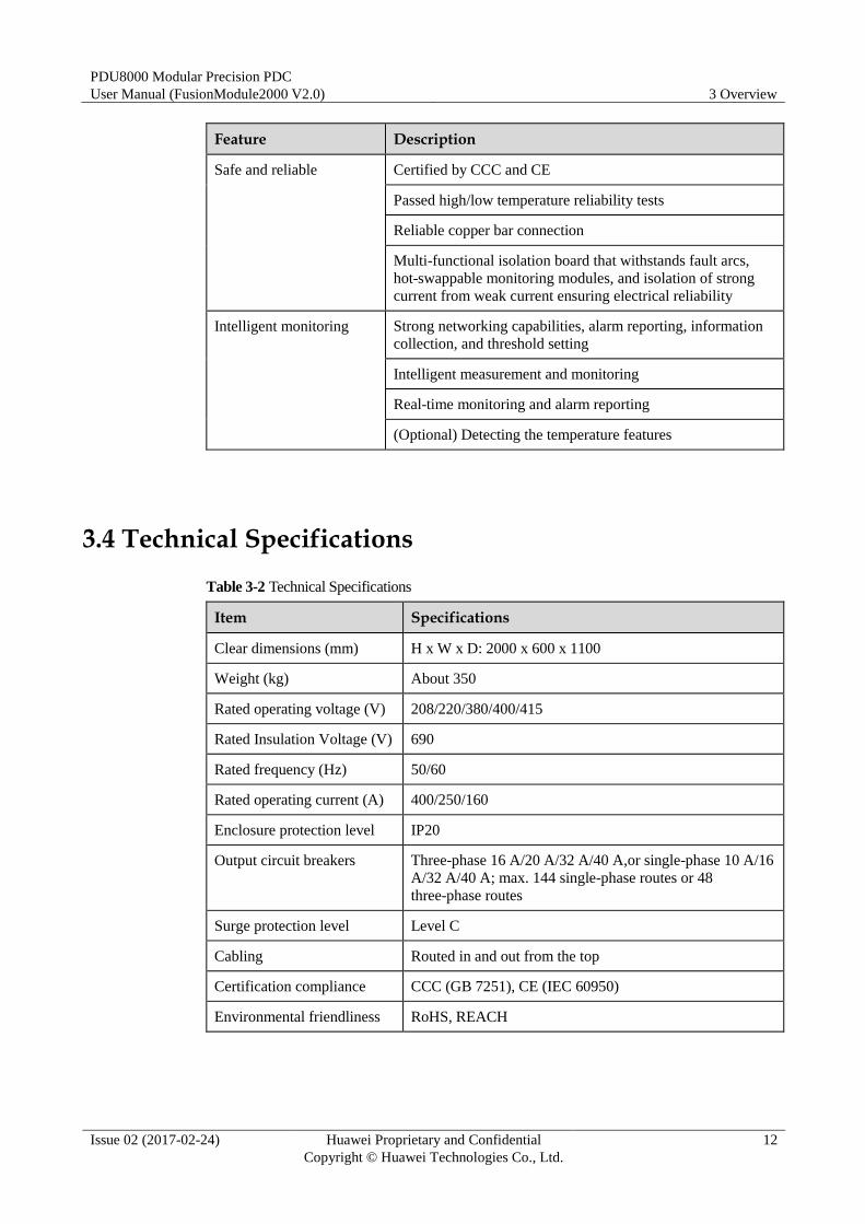
Feature Description
Safe and reliable Certified by CCC and CE
Passed high/low temperature reliability tests
Reliable copper bar connection
Multi-functional isolation board that withstands fault arcs,
hot-swappable monitoring modules, and isolation of strong
current from weak current ensuring electrical reliability
Intelligent monitoring Strong networking capabilities, alarm reporting, information
collection, and threshold setting
Intelligent measurement and monitoring
Real-time monitoring and alarm reporting
(Optional) Detecting the temperature features
3.4 Technical Specifications
Table 3-2 Technical Specifications
Item Specifications
Clear dimensions (mm) H x W x D: 2000 x 600 x 1100
Weight (kg) About 350
Rated operating voltage (V) 208/220/380/400/415
Rated Insulation Voltage (V) 690
Rated frequency (Hz) 50/60
Rated operating current (A) 400/250/160
Enclosure protection level IP20
Output circuit breakers Three-phase 16 A/20 A/32 A/40 A,or single-phase 10 A/16
A/32 A/40 A; max. 144 single-phase routes or 48
three-phase routes
Surge protection level Level C
Cabling Routed in and out from the top
Certification compliance CCC (GB 7251), CE (IEC 60950)
Environmental friendliness RoHS, REACH
PDU8000 Modular Precision PDC
User Manual (FusionModule2000 V2.0) 3 Overview
Issue 02 (2017-02-24) Huawei Proprietary and Confidential
Copyright © Huawei Technologies Co., Ltd.
13
3.5 Modules
A modular precision PDC mainly consists of the structural module, power distribution module,
monitoring module, and accessories.
3.5.1 Configuration Principle
General Principles
A modular precision PDC consists of the cabinet, power distribution subracks, MCCBs,
MCBs, cables, wiring terminals, fuse suite, indicators, and transformers. Determine the
specifications and quantity of MCCBs and MCBs to be configured based on the requirement.
Number of inputs: single or dual inputs
Input capacity: 400 A/250 A/160 A
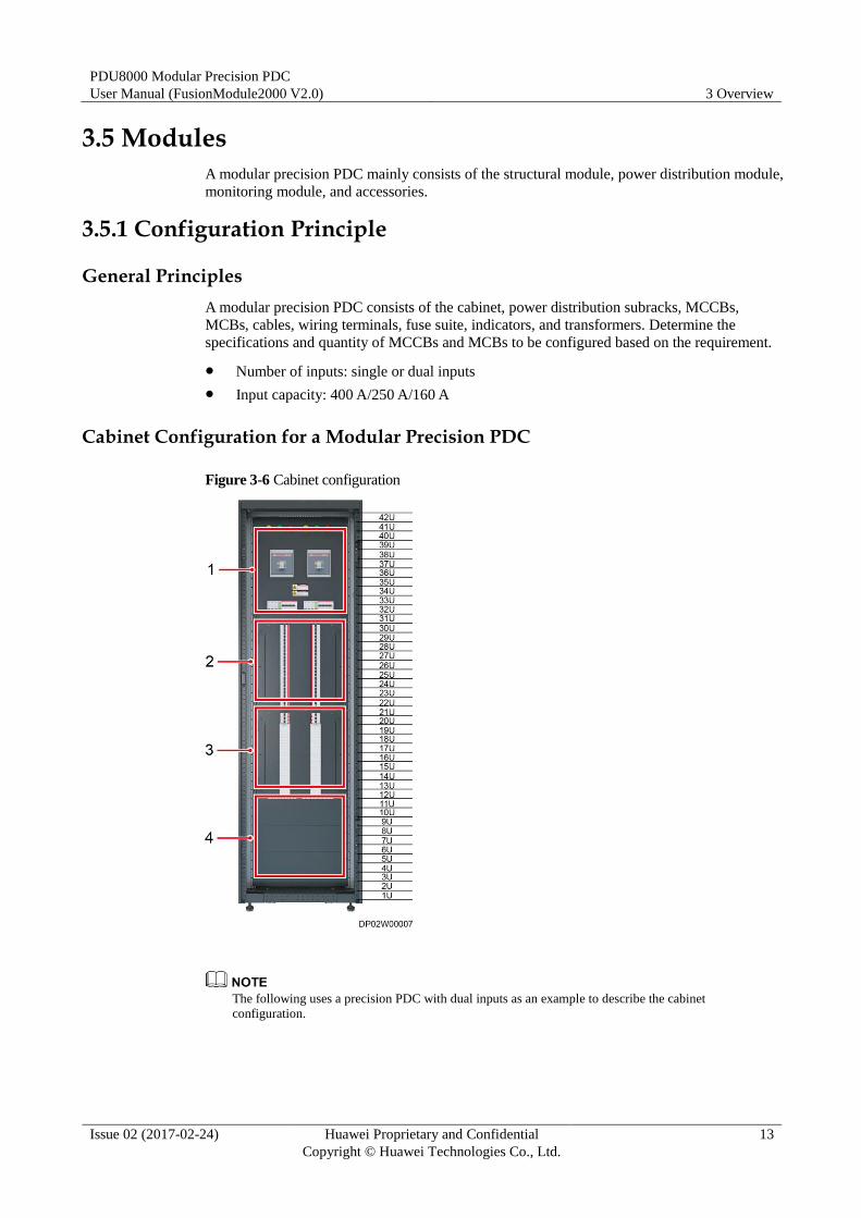
Cabinet Configuration for a Modular Precision PDC
Figure 3-6 Cabinet configuration
The following uses a precision PDC with dual inputs as an example to describe the cabinet
configuration.
PDU8000 Modular Precision PDC
User Manual (FusionModule2000 V2.0) 3 Overview
Issue 02 (2017-02-24) Huawei Proprietary and Confidential
Copyright © Huawei Technologies Co., Ltd.
14
Table 3-3 Configuration description
No. Cabinet Configuration Height
1 Input module 10 U
2 Output module 1 10 U
3 Output module 2 10 U
4 Output module 3 10 U
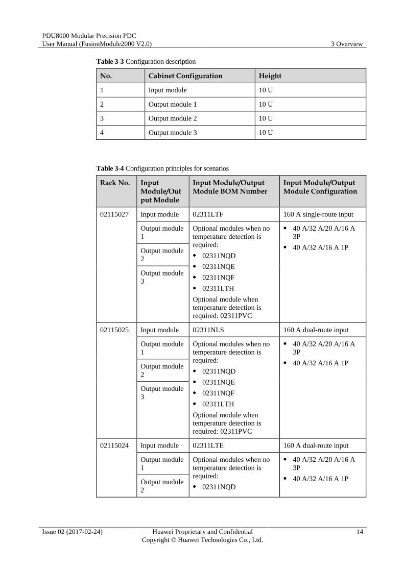
Table 3-4 Configuration principles for scenarios
Rack No. Input Module/Output Module
Input Module/Output Module BOM Number
Input Module/Output Module Configuration
02115027 Input module 02311LTF 160 A single-route input
Output module
1
Optional modules when no
temperature detection is
required:
02311NQD
02311NQE
02311NQF
02311LTH
Optional module when
temperature detection is
required: 02311PVC
40 A/32 A/20 A/16 A
3P
40 A/32 A/16 A 1P Output module
2
Output module
3
02115025 Input module 02311NLS 160 A dual-route input
Output module
1
Optional modules when no
temperature detection is
required:
02311NQD
02311NQE
02311NQF
02311LTH
Optional module when
temperature detection is
required: 02311PVC
40 A/32 A/20 A/16 A
3P
40 A/32 A/16 A 1P Output module
2
Output module
3
02115024 Input module 02311LTE 160 A dual-route input
Output module
1
Optional modules when no
temperature detection is
required:
02311NQD
40 A/32 A/20 A/16 A
3P
40 A/32 A/16 A 1P Output module
2
PDU8000 Modular Precision PDC
User Manual (FusionModule2000 V2.0) 3 Overview
Issue 02 (2017-02-24) Huawei Proprietary and Confidential
Copyright © Huawei Technologies Co., Ltd.
15
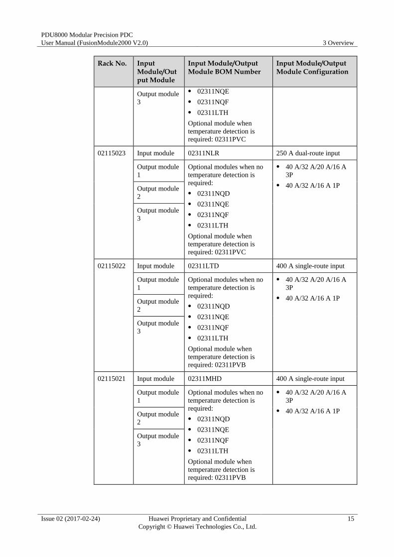
Rack No. Input Module/Output Module
Input Module/Output Module BOM Number
Input Module/Output Module Configuration
Output module
3
02311NQE
02311NQF
02311LTH
Optional module when
temperature detection is
required: 02311PVC
02115023 Input module 02311NLR 250 A dual-route input
Output module
1
Optional modules when no
temperature detection is
required:
02311NQD
02311NQE
02311NQF
02311LTH
Optional module when
temperature detection is
required: 02311PVC
40 A/32 A/20 A/16 A
3P
40 A/32 A/16 A 1P Output module
2
Output module
3
02115022 Input module 02311LTD 400 A single-route input
Output module
1
Optional modules when no
temperature detection is
required:
02311NQD
02311NQE
02311NQF
02311LTH
Optional module when
temperature detection is
required: 02311PVB
40 A/32 A/20 A/16 A
3P
40 A/32 A/16 A 1P Output module
2
Output module
3
02115021 Input module 02311MHD 400 A single-route input
Output module
1
Optional modules when no
temperature detection is
required:
02311NQD
02311NQE
02311NQF
02311LTH
Optional module when
temperature detection is
required: 02311PVB
40 A/32 A/20 A/16 A
3P
40 A/32 A/16 A 1P Output module
2
Output module
3
PDU8000 Modular Precision PDC
User Manual (FusionModule2000 V2.0) 3 Overview
Issue 02 (2017-02-24) Huawei Proprietary and Confidential
Copyright © Huawei Technologies Co., Ltd.
16
In the actual configuration, cabinet temperature detection is an optional feature.
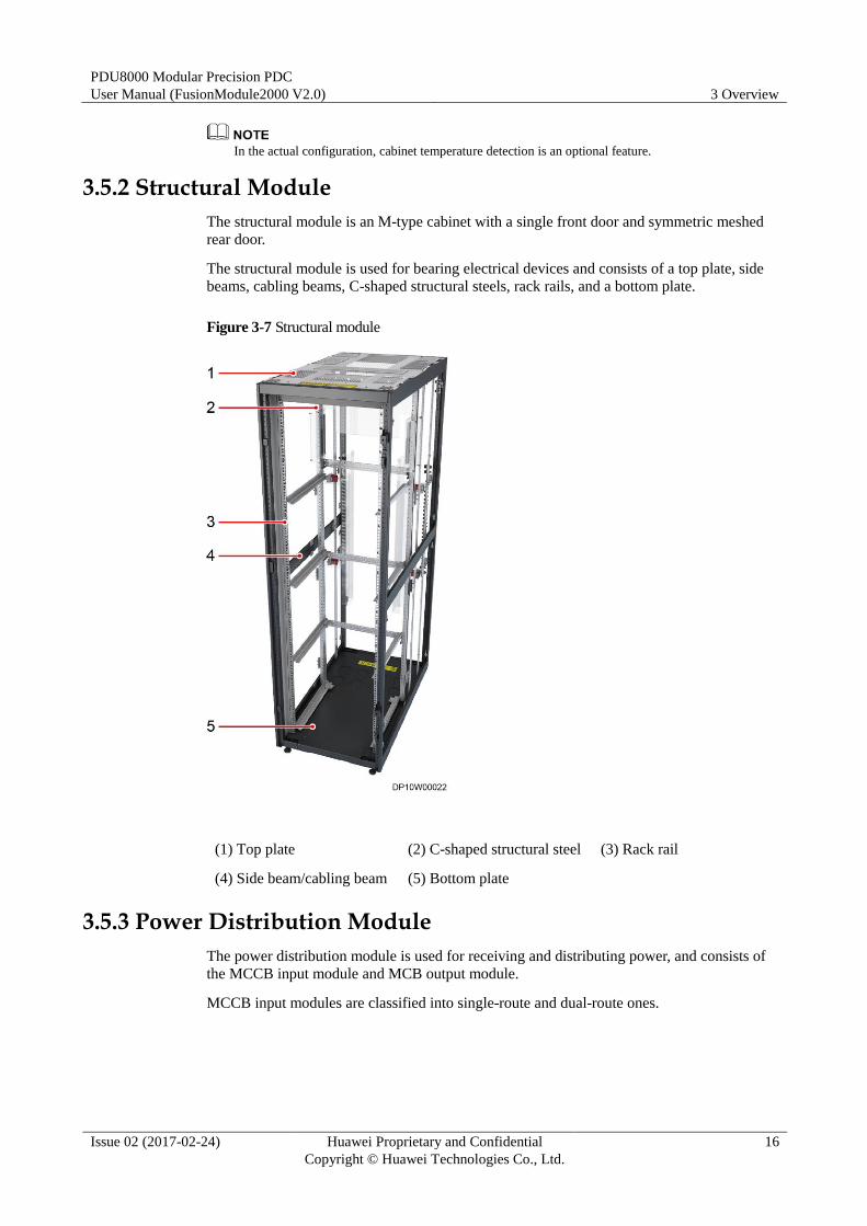
3.5.2 Structural Module
The structural module is an M-type cabinet with a single front door and symmetric meshed
rear door.
The structural module is used for bearing electrical devices and consists of a top plate, side
beams, cabling beams, C-shaped structural steels, rack rails, and a bottom plate.
Figure 3-7 Structural module
(1) Top plate (2) C-shaped structural steel (3) Rack rail
(4) Side beam/cabling beam (5) Bottom plate
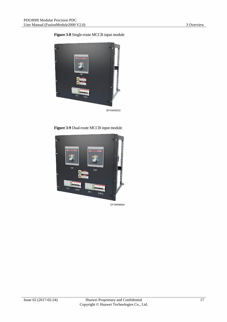
3.5.3 Power Distribution Module
The power distribution module is used for receiving and distributing power, and consists of
the MCCB input module and MCB output module.
MCCB input modules are classified into single-route and dual-route ones.
PDU8000 Modular Precision PDC
User Manual (FusionModule2000 V2.0) 3 Overview
Issue 02 (2017-02-24) Huawei Proprietary and Confidential
Copyright © Huawei Technologies Co., Ltd.
17
Figure 3-8 Single-route MCCB input module
Figure 3-9 Dual-route MCCB input module
PDU8000 Modular Precision PDC
User Manual (FusionModule2000 V2.0) 3 Overview
Issue 02 (2017-02-24) Huawei Proprietary and Confidential
Copyright © Huawei Technologies Co., Ltd.
18
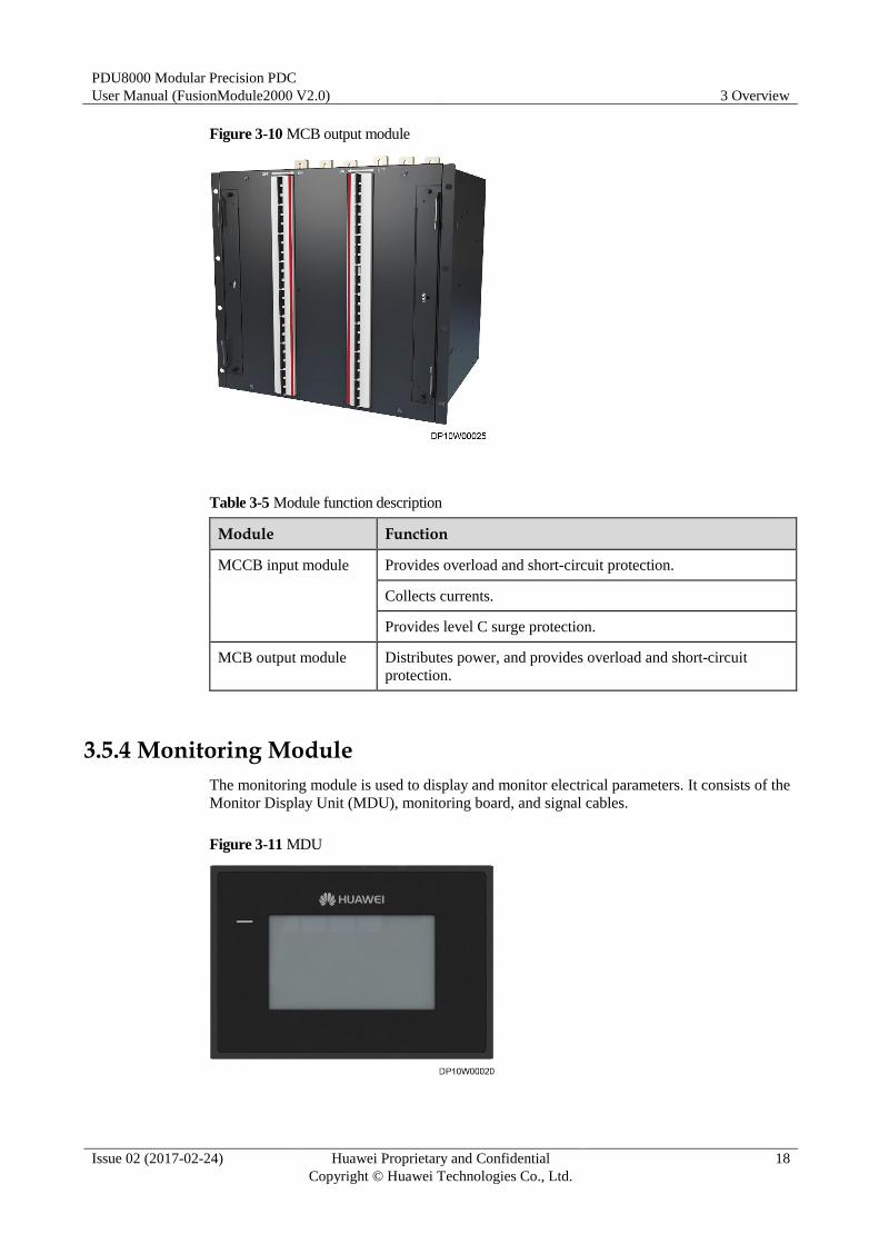
Figure 3-10 MCB output module
Table 3-5 Module function description
Module Function
MCCB input module Provides overload and short-circuit protection.
Collects currents.
Provides level C surge protection.
MCB output module Distributes power, and provides overload and short-circuit
protection.
3.5.4 Monitoring Module
The monitoring module is used to display and monitor electrical parameters. It consists of the
Monitor Display Unit (MDU), monitoring board, and signal cables.
Figure 3-11 MDU
PDU8000 Modular Precision PDC
User Manual (FusionModule2000 V2.0) 3 Overview
Issue 02 (2017-02-24) Huawei Proprietary and Confidential
Copyright © Huawei Technologies Co., Ltd.
19
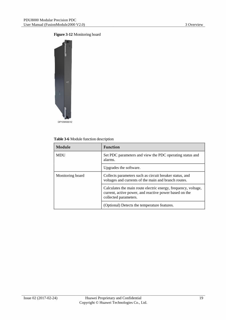
Figure 3-12 Monitoring board
Table 3-6 Module function description
Module Function
MDU Set PDC parameters and view the PDC operating status and
alarms.
Upgrades the software.
Monitoring board Collects parameters such as circuit breaker status, and
voltages and currents of the main and branch routes.
Calculates the main route electric energy, frequency, voltage,
current, active power, and reactive power based on the
collected parameters.
(Optional) Detects the temperature features.
PDU8000 Modular Precision PDC
User Manual (FusionModule2000 V2.0) 3 Overview
Issue 02 (2017-02-24) Huawei Proprietary and Confidential
Copyright © Huawei Technologies Co., Ltd.
20
3.6 Components
3.6.1 MDU
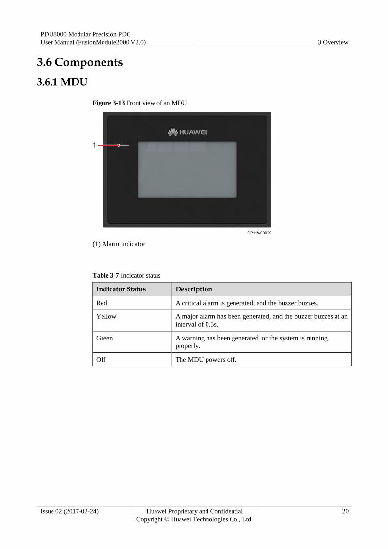
Figure 3-13 Front view of an MDU
(1) Alarm indicator
Table 3-7 Indicator status
Indicator Status Description
Red A critical alarm is generated, and the buzzer buzzes.
Yellow A major alarm has been generated, and the buzzer buzzes at an
interval of 0.5s.
Green A warning has been generated, or the system is running
properly.
Off The MDU powers off.
PDU8000 Modular Precision PDC
User Manual (FusionModule2000 V2.0) 3 Overview
Issue 02 (2017-02-24) Huawei Proprietary and Confidential
Copyright © Huawei Technologies Co., Ltd.
21
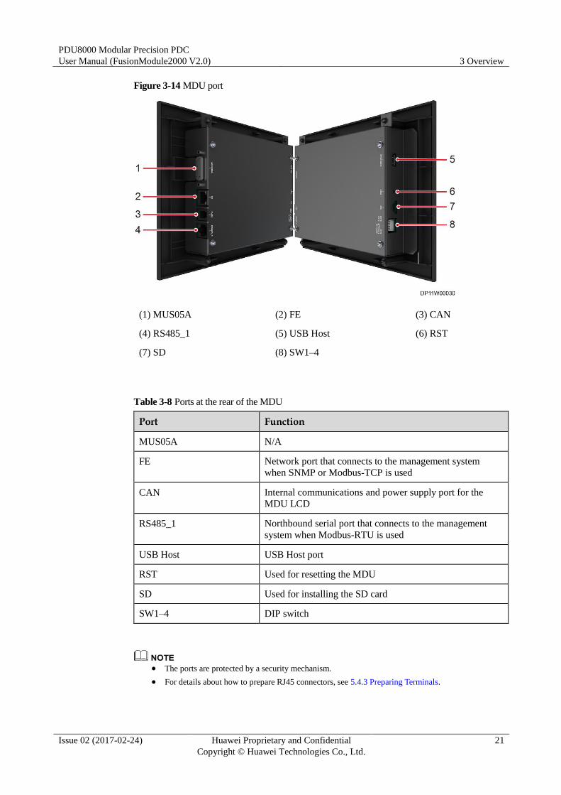
Figure 3-14 MDU port
(1) MUS05A (2) FE (3) CAN
(4) RS485_1 (5) USB Host (6) RST
(7) SD (8) SW1–4
Table 3-8 Ports at the rear of the MDU
Port Function
MUS05A N/A
FE Network port that connects to the management system
when SNMP or Modbus-TCP is used
CAN Internal communications and power supply port for the
MDU LCD
RS485_1 Northbound serial port that connects to the management
system when Modbus-RTU is used
USB Host USB Host port
RST Used for resetting the MDU
SD Used for installing the SD card
SW1–4 DIP switch
The ports are protected by a security mechanism.
For details about how to prepare RJ45 connectors, see 5.4.3 Preparing Terminals.
PDU8000 Modular Precision PDC
User Manual (FusionModule2000 V2.0) 3 Overview
Issue 02 (2017-02-24) Huawei Proprietary and Confidential
Copyright © Huawei Technologies Co., Ltd.
22
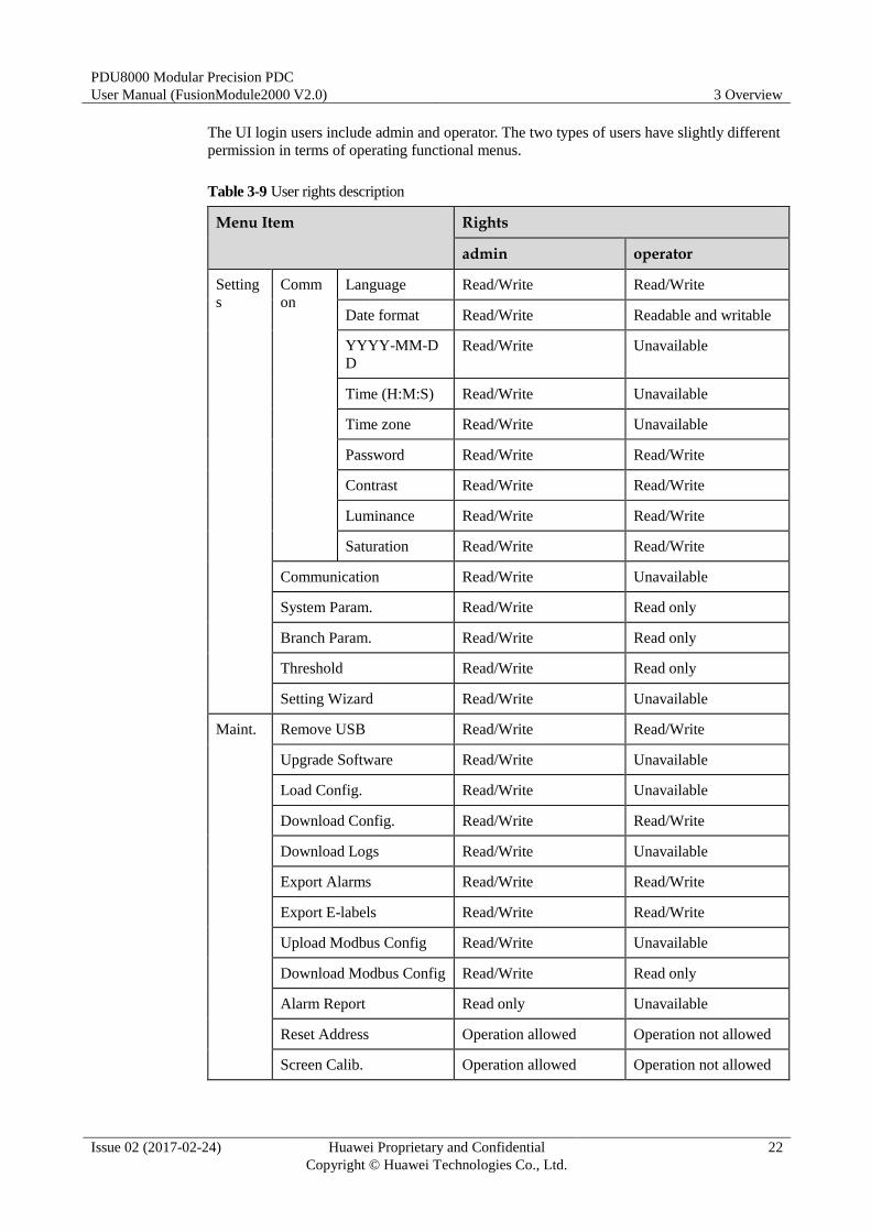
The UI login users include admin and operator. The two types of users have slightly different
permission in terms of operating functional menus.
Table 3-9 User rights description
Menu Item Rights
admin operator
Setting
s
Comm
on
Language Read/Write Read/Write
Date format Read/Write Readable and writable
YYYY-MM-D
D
Read/Write Unavailable
Time (H:M:S) Read/Write Unavailable
Time zone Read/Write Unavailable
Password Read/Write Read/Write
Contrast Read/Write Read/Write
Luminance Read/Write Read/Write
Saturation Read/Write Read/Write
Communication Read/Write Unavailable
System Param. Read/Write Read only
Branch Param. Read/Write Read only
Threshold Read/Write Read only
Setting Wizard Read/Write Unavailable
Maint. Remove USB Read/Write Read/Write
Upgrade Software Read/Write Unavailable
Load Config. Read/Write Unavailable
Download Config. Read/Write Read/Write
Download Logs Read/Write Unavailable
Export Alarms Read/Write Read/Write
Export E-labels Read/Write Read/Write
Upload Modbus Config Read/Write Unavailable
Download Modbus Config Read/Write Read only
Alarm Report Read only Unavailable
Reset Address Operation allowed Operation not allowed
Screen Calib. Operation allowed Operation not allowed
PDU8000 Modular Precision PDC
User Manual (FusionModule2000 V2.0) 3 Overview
Issue 02 (2017-02-24) Huawei Proprietary and Confidential
Copyright © Huawei Technologies Co., Ltd.
23
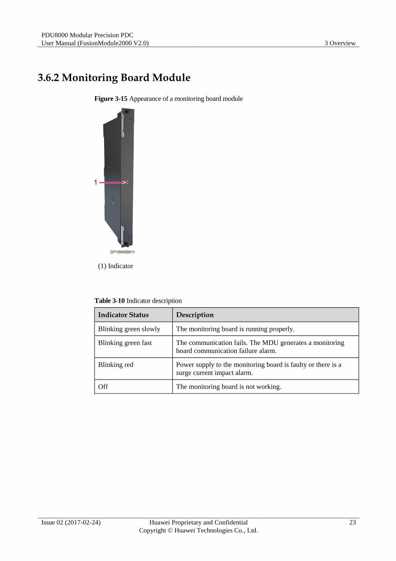
3.6.2 Monitoring Board Module
Figure 3-15 Appearance of a monitoring board module
(1) Indicator
Table 3-10 Indicator description
Indicator Status Description
Blinking green slowly The monitoring board is running properly.
Blinking green fast The communication fails. The MDU generates a monitoring
board communication failure alarm.
Blinking red Power supply to the monitoring board is faulty or there is a
surge current impact alarm.
Off The monitoring board is not working.
PDU8000 Modular Precision PDC
User Manual (FusionModule2000 V2.0) 3 Overview
Issue 02 (2017-02-24) Huawei Proprietary and Confidential
Copyright © Huawei Technologies Co., Ltd.
24
3.6.3 MCCB
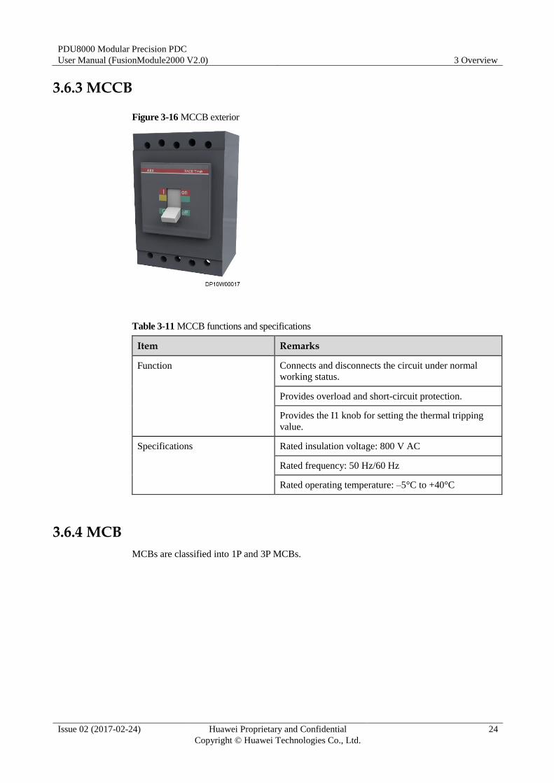
Figure 3-16 MCCB exterior
Table 3-11 MCCB functions and specifications
Item Remarks
Function Connects and disconnects the circuit under normal
working status.
Provides overload and short-circuit protection.
Provides the I1 knob for setting the thermal tripping
value.
Specifications Rated insulation voltage: 800 V AC
Rated frequency: 50 Hz/60 Hz
Rated operating temperature: –5°C to +40°C
3.6.4 MCB
MCBs are classified into 1P and 3P MCBs.
PDU8000 Modular Precision PDC
User Manual (FusionModule2000 V2.0) 3 Overview
Issue 02 (2017-02-24) Huawei Proprietary and Confidential
Copyright © Huawei Technologies Co., Ltd.
25
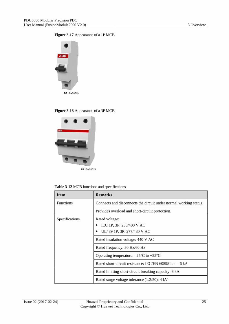
Figure 3-17 Appearance of a 1P MCB
Figure 3-18 Appearance of a 3P MCB
Table 3-12 MCB functions and specifications
Item Remarks
Functions Connects and disconnects the circuit under normal working status.
Provides overload and short-circuit protection.
Specifications Rated voltage:
IEC 1P, 3P: 230/400 V AC
UL489 1P, 3P: 277/480 V AC
Rated insulation voltage: 440 V AC
Rated frequency: 50 Hz/60 Hz
Operating temperature: –25°C to +55°C
Rated short-circuit resistance: IEC/EN 60898 Icn = 6 kA
Rated limiting short-circuit breaking capacity: 6 kA
Rated surge voltage tolerance (1.2/50): 4 kV
PDU8000 Modular Precision PDC
User Manual (FusionModule2000 V2.0) 3 Overview
Issue 02 (2017-02-24) Huawei Proprietary and Confidential
Copyright © Huawei Technologies Co., Ltd.
26
Item Remarks
Pyromagnetic tripping:
B: 3 In ≤ Im ≤ 5 In
C: 5 In ≤ Im ≤ 10 In
D: 10 In ≤ Im ≤ 20 In
K: 10 In ≤ Im ≤ 14 In
Z: 2 In ≤ Im ≤ 3 In

PDU8000 Modular Precision PDC
User Manual (FusionModule2000 V2.0) 4 Acceptance Guide
Issue 02 (2017-02-24) Huawei Proprietary and Confidential
Copyright © Huawei Technologies Co., Ltd.
27
4 Acceptance Guide
Packing List
The packing materials of a modular precision PDC include:
Wooden pallet
Moisture-proof plastic bag
Corner protector
Carton
Cushion foam
Unpacking and Accepting Goods
If any damage is found, report it to the carrier immediately.
After the equipment is delivered to the installation site, representatives from the customer
and Huawei unpack and inspect the equipment together.
Move the cabinet with caution to avoid bumping or toppling. To avoid damaging the
equipment, exercise caution when removing the packing materials.
Step 1 Check whether the tiltwatch indicator on the carton has turned red. If yes, record the
information and contact the equipment carrier and the local Huawei office immediately.
Step 2 Visually inspect the equipment appearance to check whether the equipment is paint-peeling,
misshapen, scratched, or soaked. If yes, record the information and contact the equipment
carrier and the local Huawei office immediately.
Step 3 Check against the delivery list that the equipment and fittings are correct and complete. If
some fittings are missing or do not comply with the models in the packing list, record the
information and contact the local Huawei office immediately.
----End
PDU8000 Modular Precision PDC
User Manual (FusionModule2000 V2.0) 4 Acceptance Guide
Issue 02 (2017-02-24) Huawei Proprietary and Confidential
Copyright © Huawei Technologies Co., Ltd.
28
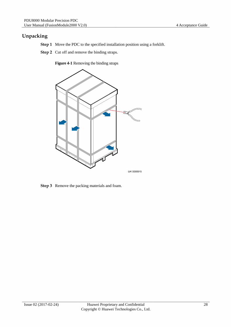
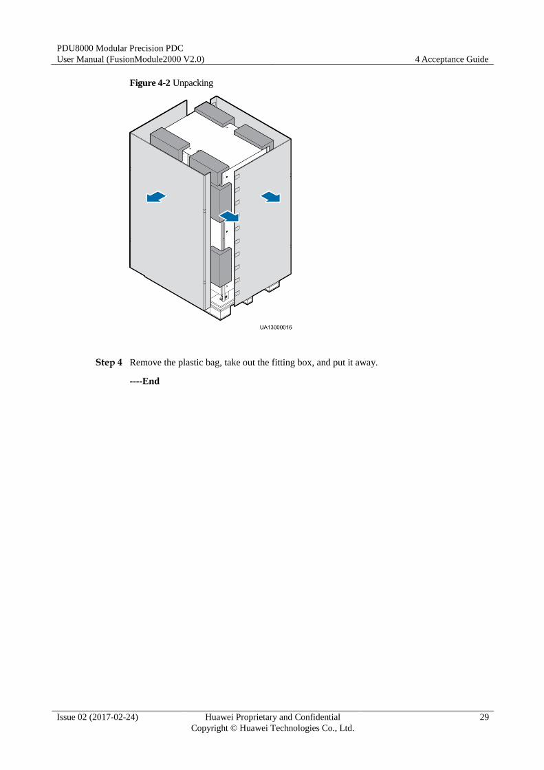
Unpacking
Step 1 Move the PDC to the specified installation position using a forklift.
Step 2 Cut off and remove the binding straps.
Figure 4-1 Removing the binding straps
Step 3 Remove the packing materials and foam.
PDU8000 Modular Precision PDC
User Manual (FusionModule2000 V2.0) 4 Acceptance Guide
Issue 02 (2017-02-24) Huawei Proprietary and Confidential
Copyright © Huawei Technologies Co., Ltd.
29
Figure 4-2 Unpacking
Step 4 Remove the plastic bag, take out the fitting box, and put it away.
----End
PDU8000 Modular Precision PDC
User Manual (FusionModule2000 V2.0) 5 Installation Guide
Issue 02 (2017-02-24) Huawei Proprietary and Confidential
Copyright © Huawei Technologies Co., Ltd.
30
5 Installation Guide
5.1 Site Requirements
The PDC site requirements are as follows:
Far away from dust, smoke, harmful gas, and corrosive, flammable, or explosive objects.
Free of interference from strong electromagnetic fields.
Cabling space should be planned for the site, and cable ladders and cable trays should be
designed for the PDC installation position.
The levelness error of the concrete pad must be less than 10 mm.
The power grid must meet the PDC input rating requirements.
Class C surge protection must be provided.
Temperature: –5°C to +40°C
Humidity: 5%–90% RH
Altitude: < 2000 m (Derated when the altitude exceeds 2000 m). For the derating details,
contact Huawei technical support.
5.2 Installation Preparations
Before installation, unpack and check the product, make available all required technical
documents, tools, and materials, check the installation environment, and train onsite
installation personnel.
5.2.1 Obtaining Technical Documents
Table 5-1 Technical documents
Technical Document Function Obtaining Method
Schematic diagram Describes the control
relationship of circuit
breakers for the PDC.
Delivered with the product.
PDU8000 Modular Precision PDC
User Manual (FusionModule2000 V2.0) 5 Installation Guide
Issue 02 (2017-02-24) Huawei Proprietary and Confidential
Copyright © Huawei Technologies Co., Ltd.
31
Technical Document Function Obtaining Method
Shipping List Describes the products and
their quantities for onsite
verification during
acceptance.
Delivered with the product.
PDU8000 Modbus Protocol
for External Systems
Enables configuration
upload and download.
Download this document
from
http://support.huawei.com.
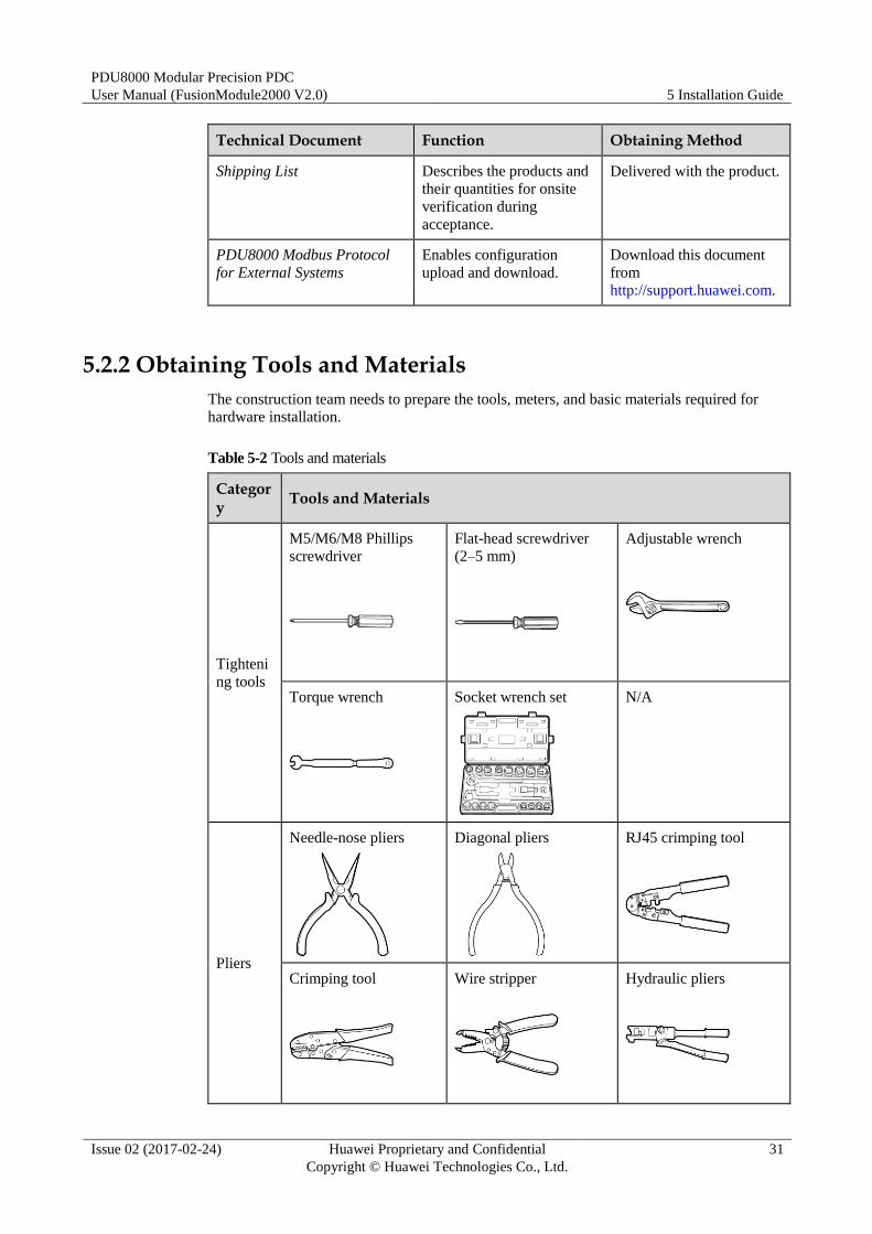
5.2.2 Obtaining Tools and Materials
The construction team needs to prepare the tools, meters, and basic materials required for
hardware installation.
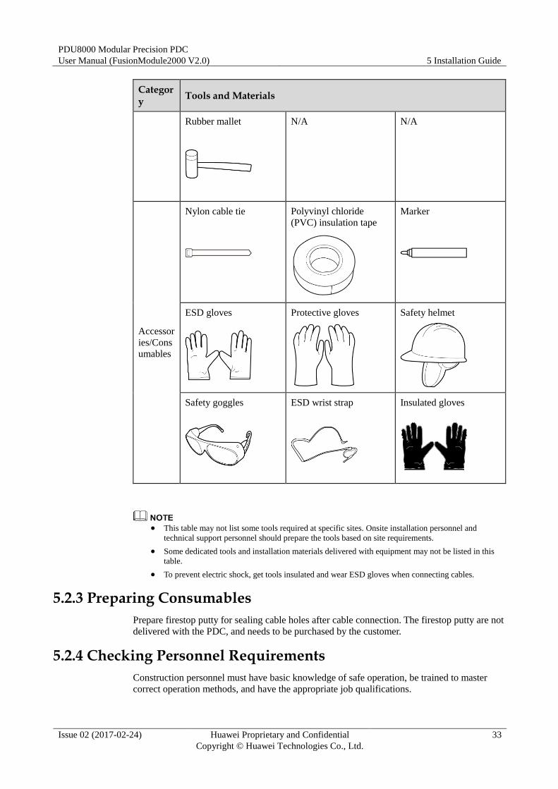
Table 5-2 Tools and materials
Category
Tools and Materials
Tighteni
ng tools
M5/M6/M8 Phillips
screwdriver
Flat-head screwdriver
(2–5 mm)
Adjustable wrench
Torque wrench
Socket wrench set
N/A
Pliers
Needle-nose pliers
Diagonal pliers
RJ45 crimping tool
Crimping tool
Wire stripper
Hydraulic pliers
PDU8000 Modular Precision PDC
User Manual (FusionModule2000 V2.0) 5 Installation Guide
Issue 02 (2017-02-24) Huawei Proprietary and Confidential
Copyright © Huawei Technologies Co., Ltd.
32
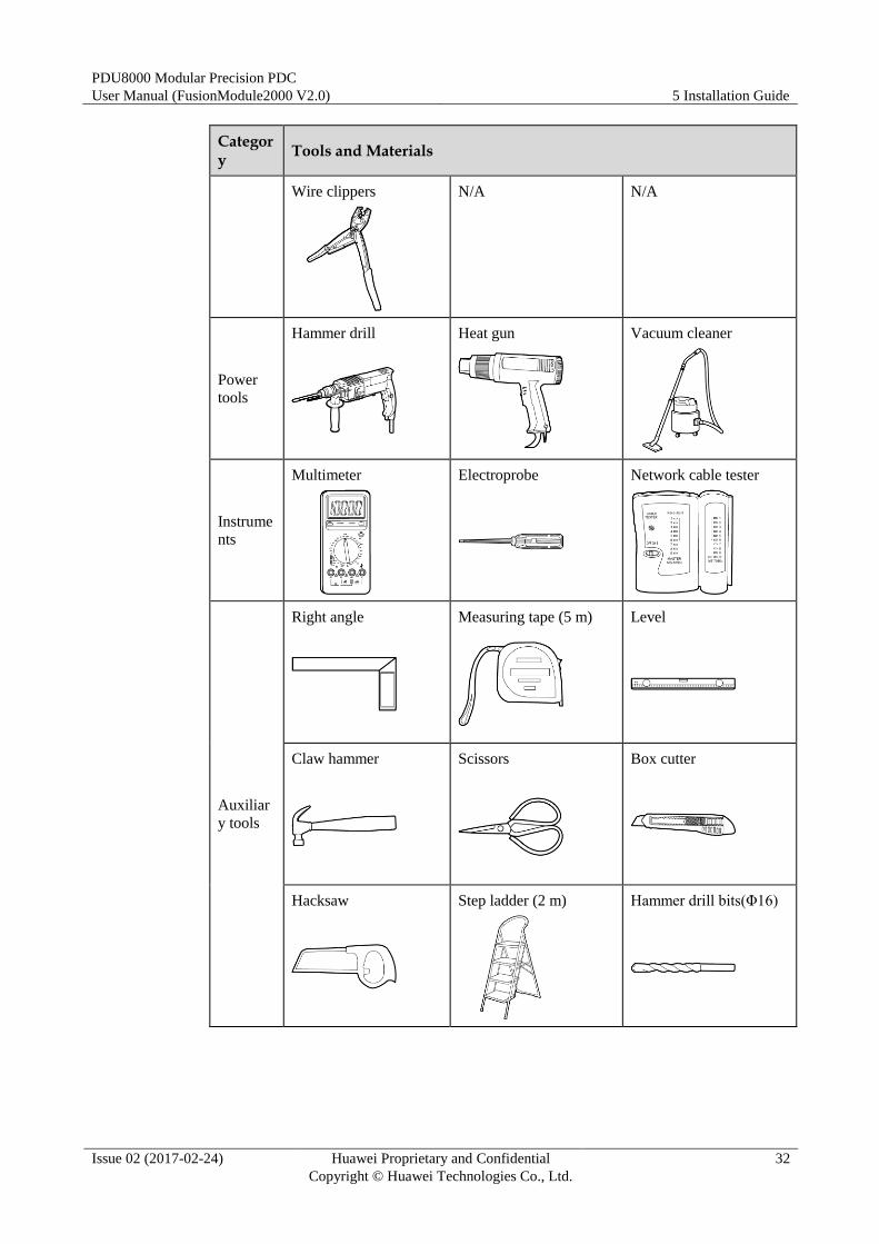
Category
Tools and Materials
Wire clippers
N/A N/A
Power
tools
Hammer drill
Heat gun
Vacuum cleaner
Instrume
nts
Multimeter
Electroprobe
Network cable tester
Auxiliar
y tools
Right angle
Measuring tape (5 m)
Level
Claw hammer
Scissors
Box cutter
Hacksaw
Step ladder (2 m)
Hammer drill bits(Φ16)
PDU8000 Modular Precision PDC
User Manual (FusionModule2000 V2.0) 5 Installation Guide
Issue 02 (2017-02-24) Huawei Proprietary and Confidential
Copyright © Huawei Technologies Co., Ltd.
33
Category
Tools and Materials
Rubber mallet
N/A N/A
Accessor
ies/Cons
umables
Nylon cable tie
Polyvinyl chloride
(PVC) insulation tape
Marker
ESD gloves
Protective gloves
Safety helmet
Safety goggles
ESD wrist strap
Insulated gloves
This table may not list some tools required at specific sites. Onsite installation personnel and
technical support personnel should prepare the tools based on site requirements.
Some dedicated tools and installation materials delivered with equipment may not be listed in this
table.
To prevent electric shock, get tools insulated and wear ESD gloves when connecting cables.
5.2.3 Preparing Consumables
Prepare firestop putty for sealing cable holes after cable connection. The firestop putty are not
delivered with the PDC, and needs to be purchased by the customer.
5.2.4 Checking Personnel Requirements
Construction personnel must have basic knowledge of safe operation, be trained to master
correct operation methods, and have the appropriate job qualifications.
PDU8000 Modular Precision PDC
User Manual (FusionModule2000 V2.0) 5 Installation Guide
Issue 02 (2017-02-24) Huawei Proprietary and Confidential
Copyright © Huawei Technologies Co., Ltd.
34
The owner should pay attention to the following items when organizing the construction
personnel to carry out construction work:
Construction personnel have been trained and qualified by Huawei to master methods for
system installation and commissioning, and have obtained work permits before they
begin to install and commission equipment.
Installation personnel should be trained by Huawei and master installation and
construction methods.
The number of construction personnel depends on the project progress and the
installation environment.
Construction personnel have read through the safety precautions and related product
documents before they begin work.
5.2.5 Checking the Installation Environment
Ensure that the installation environment meets the requirements listed in 5.1 Site
Requirements before installation.
Huawei will not be liable for any consequences caused if the installation environment does not meet the
requirements.
5.3 Installing the PDC
Prerequisites The installation environment has been checked with expected results.
The site has been closed off, and notices have been posted.
The PDC has been unpacked and inspected, and no problems were found.
You have obtained the tools and meters required for the installation.
Installation personnel must be qualified and certified. Power distribution equipment
operators must hold a primary electrician certificate or higher.
Context A modular precision PDC can be installed on a concrete floor or an ESD floor.
A modular precision PDC can be deployed separately or combined with another cabinet.
As the onsite conditions may vary, the following steps are for reference only. Onsite installation
personnel and technical engineers can decide whether to perform the steps based on the actual situation.
5.3.1 Moving the PDC
Context
PDU8000 Modular Precision PDC
User Manual (FusionModule2000 V2.0) 5 Installation Guide
Issue 02 (2017-02-24) Huawei Proprietary and Confidential
Copyright © Huawei Technologies Co., Ltd.
35
The PDC weighs about 350 kg. Take protective measures during movement to prevent
toppling and bumping.
Procedure
Step 1 Move the PDC to the specified installation position using a forklift.
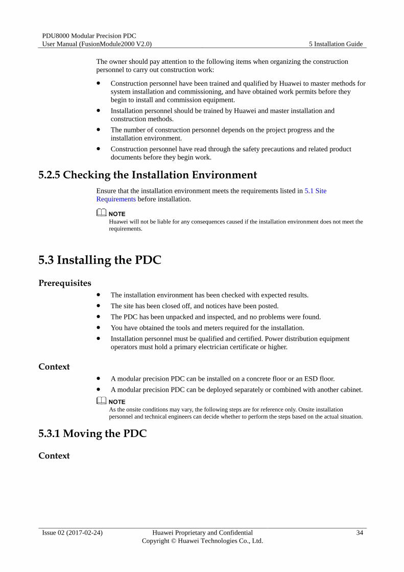
Step 2 Remove the two L-shaped brackets from the front and rear of the PDC and pallet, as shown
by (1) and (2) in Figure 5-1.
Figure 5-1 Removing L-shaped mechanical parts
Step 3 Use diagonal pliers to cut off the ties securing the unloading ramp, and take out the unloading
ramp, as shown in Figure 5-1.
Step 4 Clip the unloading ramp to the wooden pallet.
PDU8000 Modular Precision PDC
User Manual (FusionModule2000 V2.0) 5 Installation Guide
Issue 02 (2017-02-24) Huawei Proprietary and Confidential
Copyright © Huawei Technologies Co., Ltd.
36
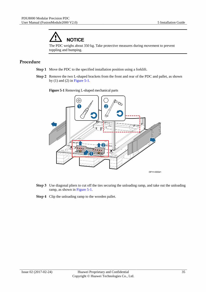
Figure 5-2 Installing the unloading ramp
Step 5 Adjust the PDC leveling feet using a wrench to ensure that all castors touch the ground.
Figure 5-3 Adjust the PDC leveling feet
To prevent cabinet tilting and avoid equipment damage, adjust all the feet instead of one foot.
PDU8000 Modular Precision PDC
User Manual (FusionModule2000 V2.0) 5 Installation Guide
Issue 02 (2017-02-24) Huawei Proprietary and Confidential
Copyright © Huawei Technologies Co., Ltd.
37
Step 6 Arrange four persons to push the PDC off the wooden pallet to the ground with caution.
----End
5.3.2 Installing the PDC on a Concrete Floor
Procedure
Step 1 Determine the PDC installation position.
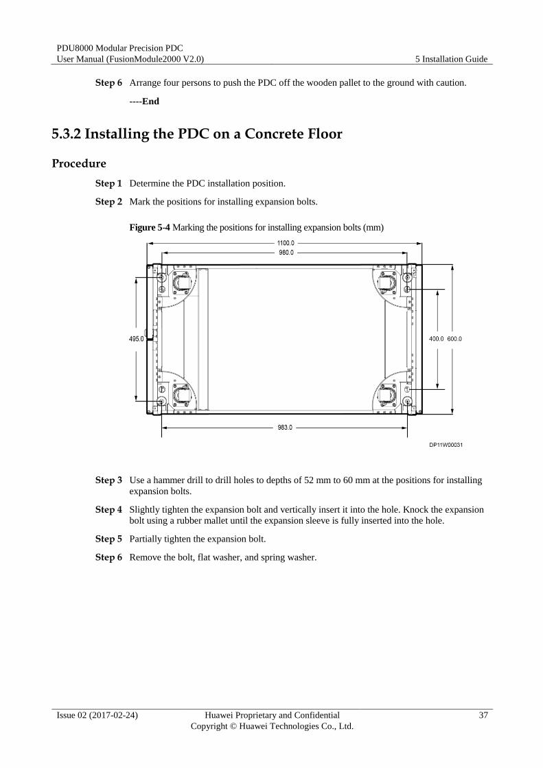
Step 2 Mark the positions for installing expansion bolts.
Figure 5-4 Marking the positions for installing expansion bolts (mm)
Step 3 Use a hammer drill to drill holes to depths of 52 mm to 60 mm at the positions for installing
expansion bolts.
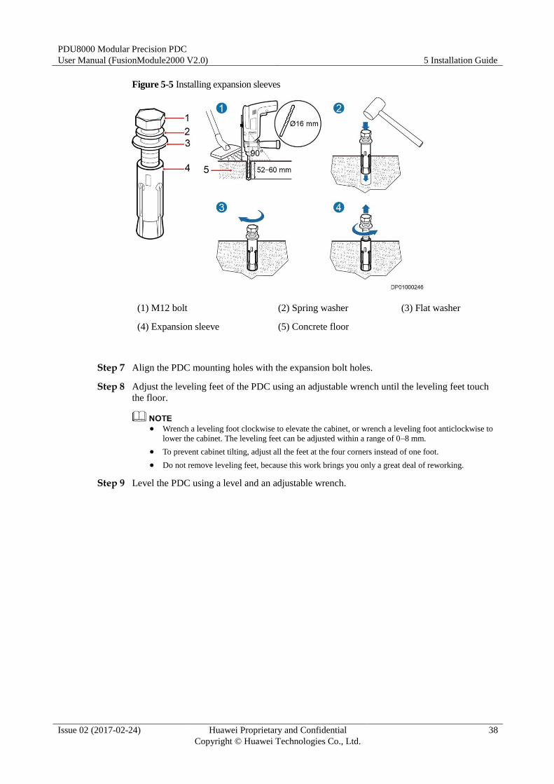
Step 4 Slightly tighten the expansion bolt and vertically insert it into the hole. Knock the expansion
bolt using a rubber mallet until the expansion sleeve is fully inserted into the hole.
Step 5 Partially tighten the expansion bolt.
Step 6 Remove the bolt, flat washer, and spring washer.
PDU8000 Modular Precision PDC
User Manual (FusionModule2000 V2.0) 5 Installation Guide
Issue 02 (2017-02-24) Huawei Proprietary and Confidential
Copyright © Huawei Technologies Co., Ltd.
38
Figure 5-5 Installing expansion sleeves
(1) M12 bolt (2) Spring washer (3) Flat washer
(4) Expansion sleeve (5) Concrete floor
Step 7 Align the PDC mounting holes with the expansion bolt holes.
Step 8 Adjust the leveling feet of the PDC using an adjustable wrench until the leveling feet touch
the floor.
Wrench a leveling foot clockwise to elevate the cabinet, or wrench a leveling foot anticlockwise to
lower the cabinet. The leveling feet can be adjusted within a range of 0–8 mm.
To prevent cabinet tilting, adjust all the feet at the four corners instead of one foot.
Do not remove leveling feet, because this work brings you only a great deal of reworking.
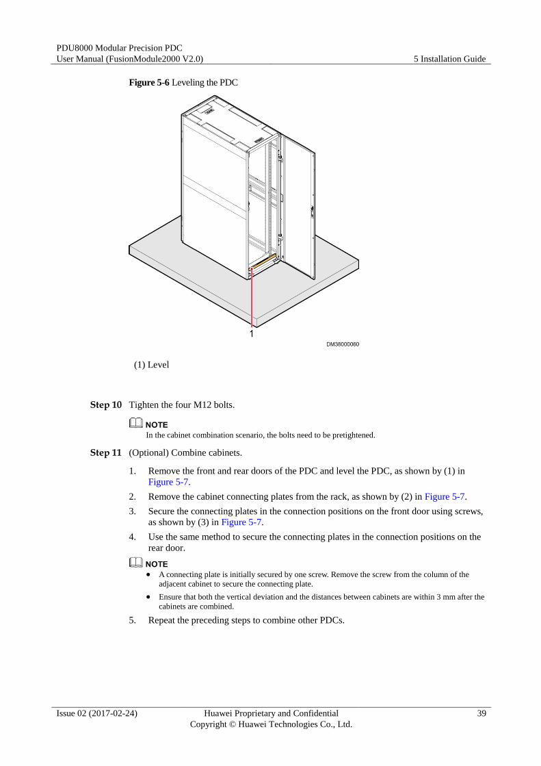
Step 9 Level the PDC using a level and an adjustable wrench.
PDU8000 Modular Precision PDC
User Manual (FusionModule2000 V2.0) 5 Installation Guide
Issue 02 (2017-02-24) Huawei Proprietary and Confidential
Copyright © Huawei Technologies Co., Ltd.
39
Figure 5-6 Leveling the PDC
(1) Level
Step 10 Tighten the four M12 bolts.
In the cabinet combination scenario, the bolts need to be pretightened.
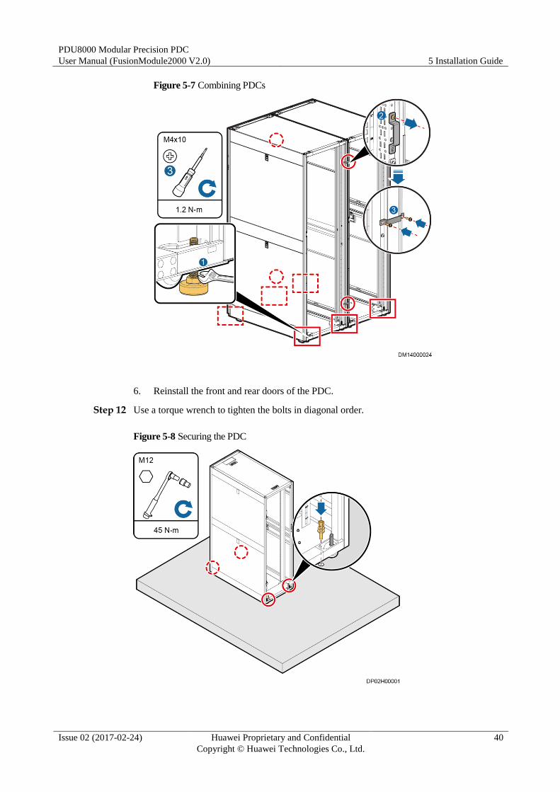
Step 11 (Optional) Combine cabinets.
1. Remove the front and rear doors of the PDC and level the PDC, as shown by (1) in
Figure 5-7.
2. Remove the cabinet connecting plates from the rack, as shown by (2) in Figure 5-7.
3. Secure the connecting plates in the connection positions on the front door using screws,
as shown by (3) in Figure 5-7.
4. Use the same method to secure the connecting plates in the connection positions on the
rear door.
A connecting plate is initially secured by one screw. Remove the screw from the column of the
adjacent cabinet to secure the connecting plate.
Ensure that both the vertical deviation and the distances between cabinets are within 3 mm after the
cabinets are combined.
5. Repeat the preceding steps to combine other PDCs.
PDU8000 Modular Precision PDC
User Manual (FusionModule2000 V2.0) 5 Installation Guide
Issue 02 (2017-02-24) Huawei Proprietary and Confidential
Copyright © Huawei Technologies Co., Ltd.
40
Figure 5-7 Combining PDCs
6. Reinstall the front and rear doors of the PDC.
Step 12 Use a torque wrench to tighten the bolts in diagonal order.
Figure 5-8 Securing the PDC
PDU8000 Modular Precision PDC
User Manual (FusionModule2000 V2.0) 5 Installation Guide
Issue 02 (2017-02-24) Huawei Proprietary and Confidential
Copyright © Huawei Technologies Co., Ltd.
41
----End
5.3.3 Installing the PDC on an ESD Floor
Context
A support is required when the PDC is installed on an ESD floor. The support height depends
on the height between the ground and the ESD floor.
Procedure
Step 1 Lower the leveling feet of the PDC using an adjustable wrench until all castors are off the
ground.
Step 2 Lift the PDC onto the support and align the mounting holes on the PDC with those on the
support.
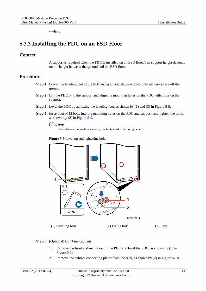
Step 3 Level the PDC by adjusting the leveling feet, as shown by (1) and (3) in Figure 5-9.
Step 4 Insert four M12 bolts into the mounting holes on the PDC and support, and tighten the bolts,
as shown by (2) in Figure 5-9.
In the cabinet combination scenario, the bolts need to be pretightened.
Figure 5-9 Leveling and tightening bolts
(1) Leveling foot (2) Fixing bolt (3) Level
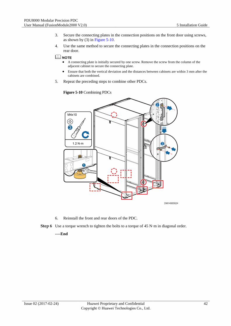
Step 5 (Optional) Combine cabinets.
1. Remove the front and rear doors of the PDC and level the PDC, as shown by (1) in
Figure 5-10.
2. Remove the cabinet connecting plates from the rack, as shown by (2) in Figure 5-10.
PDU8000 Modular Precision PDC
User Manual (FusionModule2000 V2.0) 5 Installation Guide
Issue 02 (2017-02-24) Huawei Proprietary and Confidential
Copyright © Huawei Technologies Co., Ltd.
42
3. Secure the connecting plates in the connection positions on the front door using screws,
as shown by (3) in Figure 5-10.
4. Use the same method to secure the connecting plates in the connection positions on the
rear door.
A connecting plate is initially secured by one screw. Remove the screw from the column of the
adjacent cabinet to secure the connecting plate.
Ensure that both the vertical deviation and the distances between cabinets are within 3 mm after the
cabinets are combined.
5. Repeat the preceding steps to combine other PDCs.
Figure 5-10 Combining PDCs
6. Reinstall the front and rear doors of the PDC.
Step 6 Use a torque wrench to tighten the bolts to a torque of 45 N·m in diagonal order.
----End
PDU8000 Modular Precision PDC
User Manual (FusionModule2000 V2.0) 5 Installation Guide
Issue 02 (2017-02-24) Huawei Proprietary and Confidential
Copyright © Huawei Technologies Co., Ltd.
43
5.4 Installing Cables
5.4.1 Cable Routing Rules
Binding Cables
Table 5-3 Cable binding rules
No. Cable Binding Rule
1 Power cables and signal cables are bound separately with a distance above
150 mm.
2 Both ends of a cable are labeled. Labels are clean and correct, and provide
concise and understandable description.
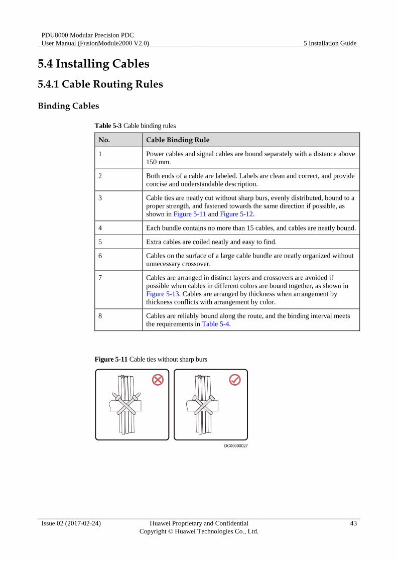
3 Cable ties are neatly cut without sharp burs, evenly distributed, bound to a
proper strength, and fastened towards the same direction if possible, as
shown in Figure 5-11 and Figure 5-12.
4 Each bundle contains no more than 15 cables, and cables are neatly bound.
5 Extra cables are coiled neatly and easy to find.
6 Cables on the surface of a large cable bundle are neatly organized without
unnecessary crossover.
7 Cables are arranged in distinct layers and crossovers are avoided if
possible when cables in different colors are bound together, as shown in
Figure 5-13. Cables are arranged by thickness when arrangement by
thickness conflicts with arrangement by color.
8 Cables are reliably bound along the route, and the binding interval meets
the requirements in Table 5-4.
Figure 5-11 Cable ties without sharp burs

PDU8000 Modular Precision PDC
User Manual (FusionModule2000 V2.0) 5 Installation Guide
Issue 02 (2017-02-24) Huawei Proprietary and Confidential
Copyright © Huawei Technologies Co., Ltd.
44
Figure 5-12 Cable ties in the same direction
Figure 5-13 Binding cables in different colors
Table 5-4 Cable binding interval
Cable Diameter (mm) Binding Interval (mm)
< 10 150
10–30 200
> 30 300
Cable Bending
Table 5-5 Cable bending rules
No. Cable Bending Rule
1 Cables are not overly bent as over bending may damage the cable cores.
2 Unless otherwise stipulated, the bending radius should be three times more
than the cable diameter if the installation space is sufficient.
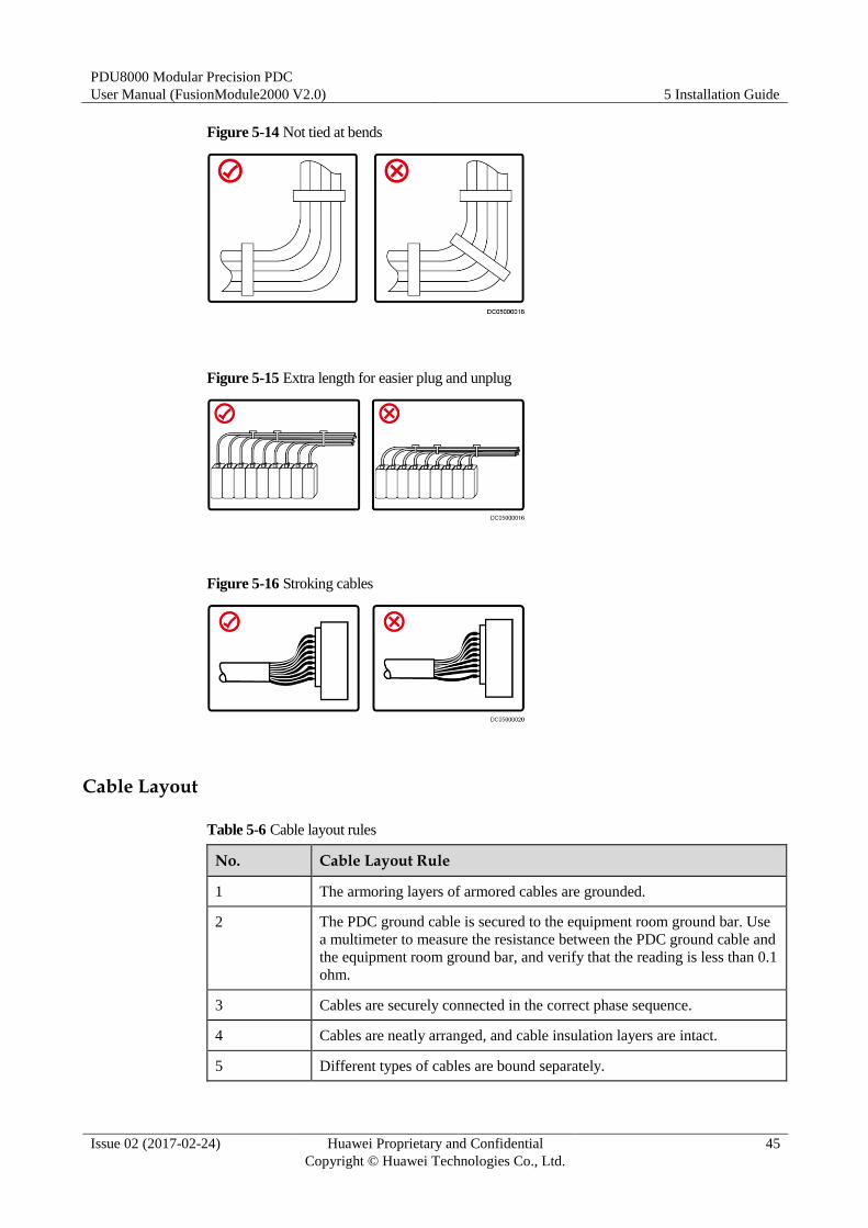
3 Cables are not tied where they bend, as shown in Figure 5-14.
4 Cables must be a little longer than the exact cable route length to facilitate
plug and unplug, as shown in Figure 5-15.
5 Cables should be stroked to eliminate abnormal stress on certain cables, as
shown in Figure 5-16.
PDU8000 Modular Precision PDC
User Manual (FusionModule2000 V2.0) 5 Installation Guide
Issue 02 (2017-02-24) Huawei Proprietary and Confidential
Copyright © Huawei Technologies Co., Ltd.
45
Figure 5-14 Not tied at bends
Figure 5-15 Extra length for easier plug and unplug
Figure 5-16 Stroking cables
Cable Layout
Table 5-6 Cable layout rules
No. Cable Layout Rule
1 The armoring layers of armored cables are grounded.
2 The PDC ground cable is secured to the equipment room ground bar. Use
a multimeter to measure the resistance between the PDC ground cable and
the equipment room ground bar, and verify that the reading is less than 0.1
ohm.
3 Cables are securely connected in the correct phase sequence.
4 Cables are neatly arranged, and cable insulation layers are intact.
5 Different types of cables are bound separately.
PDU8000 Modular Precision PDC
User Manual (FusionModule2000 V2.0) 5 Installation Guide
Issue 02 (2017-02-24) Huawei Proprietary and Confidential
Copyright © Huawei Technologies Co., Ltd.
46
No. Cable Layout Rule
6 Connection ports and cabling methods facilitate maintenance, cable
routing, and capacity expansion.
7 Cable connectors prepared onsite must be normal, secure, reliable, and
neat.
8 Power cables, ground cables, and various signal cables are securely
connected. Adapters are securely plugged or screwed.
9 The N and PE cables are bound separately from the L1/L2/L3 or L cables
for each circuit breaker. Cables are converged at the beam and bound in
groups by cable ties.
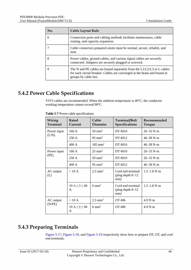
5.4.2 Power Cable Specifications
YJV5 cables are recommended. When the ambient temperature is 40°C, the conductor
working temperature cannot exceed 90°C.
Table 5-7 Power cable specifications
Wiring Terminal
Rated Current
Cable Diameter
Terminal/Bolt Specifications
Recommended Torque
Power input
(L/N)
160 A 50 mm2 DT-M10 26–33 N·m
250 A 95 mm2 DT-M12 46–58 N·m
400 A 185 mm2 DT-M16 46–58 N·m
Power input
(PE)
160 A 25 mm2 DT-M10 26–33 N·m
250 A 50 mm2 DT-M10 26–33 N·m
400 A 95 mm2 DT-M12 46–58 N·m
AC output
(L)
< 10 A 2.5 mm2 Cord end terminal
(plug depth 8–12
mm)
1.5–1.8 N·m
10 A ≤ I ≤ 40
A
6 mm2 Cord end terminal
(plug depth 8–12
mm)
1.5–1.8 N·m
AC output
(N/PE)
< 10 A 2.5 mm2 OT-M6 4.9 N·m
10 A ≤ I ≤ 40
A
6 mm2 OT-M6 4.9 N·m
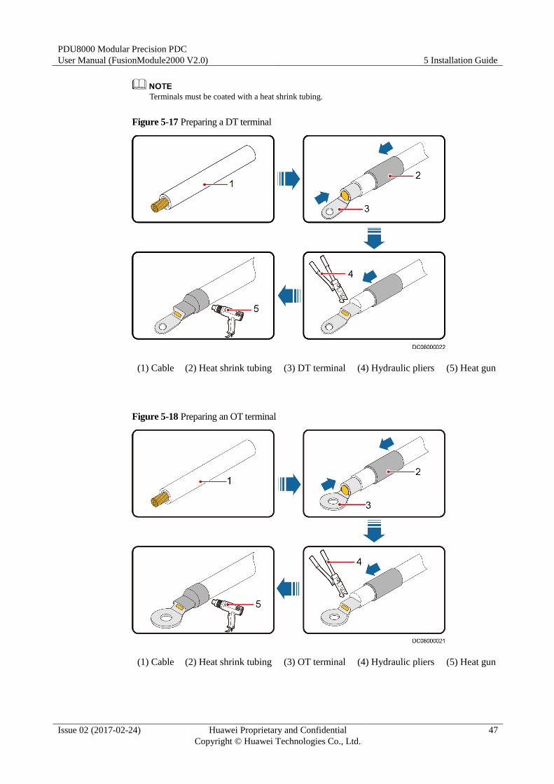
5.4.3 Preparing Terminals
Figure 5-17, Figure 5-18, and Figure 5-19 respectively show how to prepare DT, OT, and cord end terminals.
PDU8000 Modular Precision PDC
User Manual (FusionModule2000 V2.0) 5 Installation Guide
Issue 02 (2017-02-24) Huawei Proprietary and Confidential
Copyright © Huawei Technologies Co., Ltd.
47
Terminals must be coated with a heat shrink tubing.
Figure 5-17 Preparing a DT terminal
(1) Cable (2) Heat shrink tubing (3) DT terminal (4) Hydraulic pliers (5) Heat gun
Figure 5-18 Preparing an OT terminal
(1) Cable (2) Heat shrink tubing (3) OT terminal (4) Hydraulic pliers (5) Heat gun
PDU8000 Modular Precision PDC
User Manual (FusionModule2000 V2.0) 5 Installation Guide
Issue 02 (2017-02-24) Huawei Proprietary and Confidential
Copyright © Huawei Technologies Co., Ltd.
48
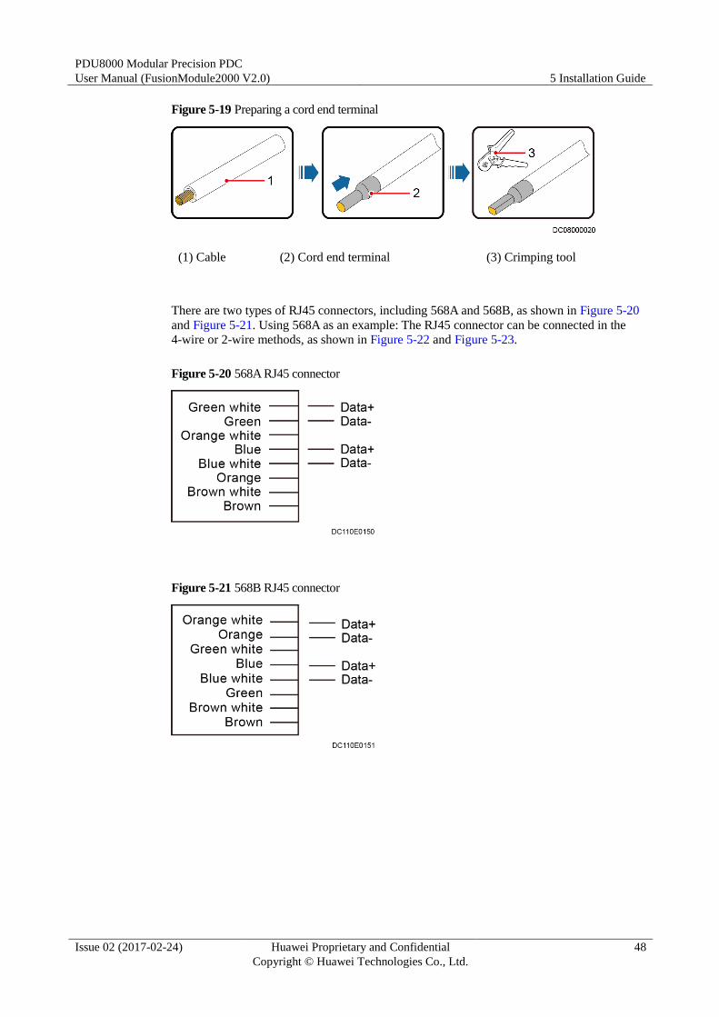
Figure 5-19 Preparing a cord end terminal
(1) Cable (2) Cord end terminal (3) Crimping tool
There are two types of RJ45 connectors, including 568A and 568B, as shown in Figure 5-20
and Figure 5-21. Using 568A as an example: The RJ45 connector can be connected in the
4-wire or 2-wire methods, as shown in Figure 5-22 and Figure 5-23.
Figure 5-20 568A RJ45 connector
Figure 5-21 568B RJ45 connector
PDU8000 Modular Precision PDC
User Manual (FusionModule2000 V2.0) 5 Installation Guide
Issue 02 (2017-02-24) Huawei Proprietary and Confidential
Copyright © Huawei Technologies Co., Ltd.
49
Figure 5-22 4-wire
Figure 5-23 2-wire
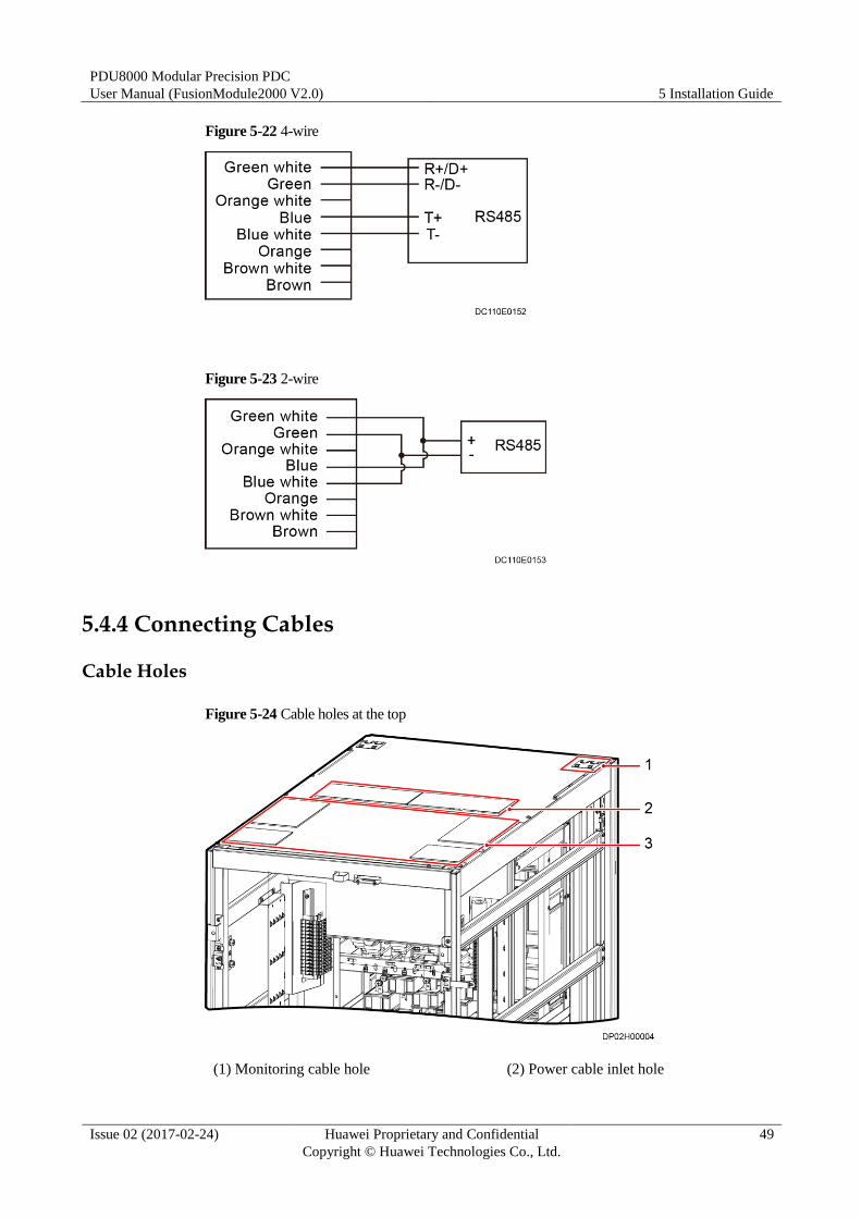
5.4.4 Connecting Cables
Cable Holes
Figure 5-24 Cable holes at the top
(1) Monitoring cable hole (2) Power cable inlet hole

PDU8000 Modular Precision PDC
User Manual (FusionModule2000 V2.0) 5 Installation Guide
Issue 02 (2017-02-24) Huawei Proprietary and Confidential
Copyright © Huawei Technologies Co., Ltd.
50
(3) Power cable outlet hole
Precautions
Ensure that all circuit breakers, including upstream output circuit breakers, are switched off
before connecting cables.
Cables for the PDC are routed from the top. This topic uses the dual-input top cabling scenario as an
example. Cable connections for other scenarios are similar.
Cable Connections
Step 1 Route cables from the top.
1. Remove a number of rodent-proof meshes from the top of the PDC based on the number
of cables to be routed.
Figure 5-25 Removing rodent-proof meshes at the top
2. Put the rodent-proof meshes aside for future use.
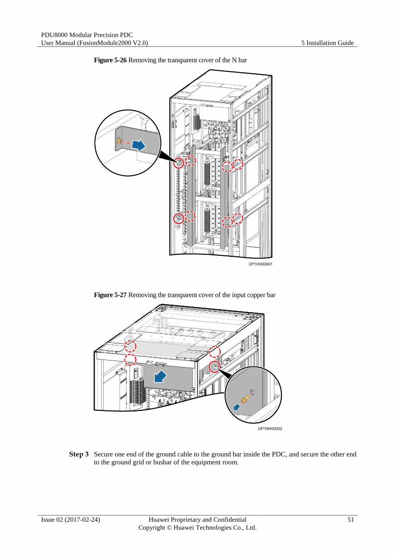
Step 2 Remove the transparent covers of the N bar and input copper bar, and put the covers aside for
future use, as shown in Figure 5-26 and Figure 5-27.
PDU8000 Modular Precision PDC
User Manual (FusionModule2000 V2.0) 5 Installation Guide
Issue 02 (2017-02-24) Huawei Proprietary and Confidential
Copyright © Huawei Technologies Co., Ltd.
51
Figure 5-26 Removing the transparent cover of the N bar
Figure 5-27 Removing the transparent cover of the input copper bar
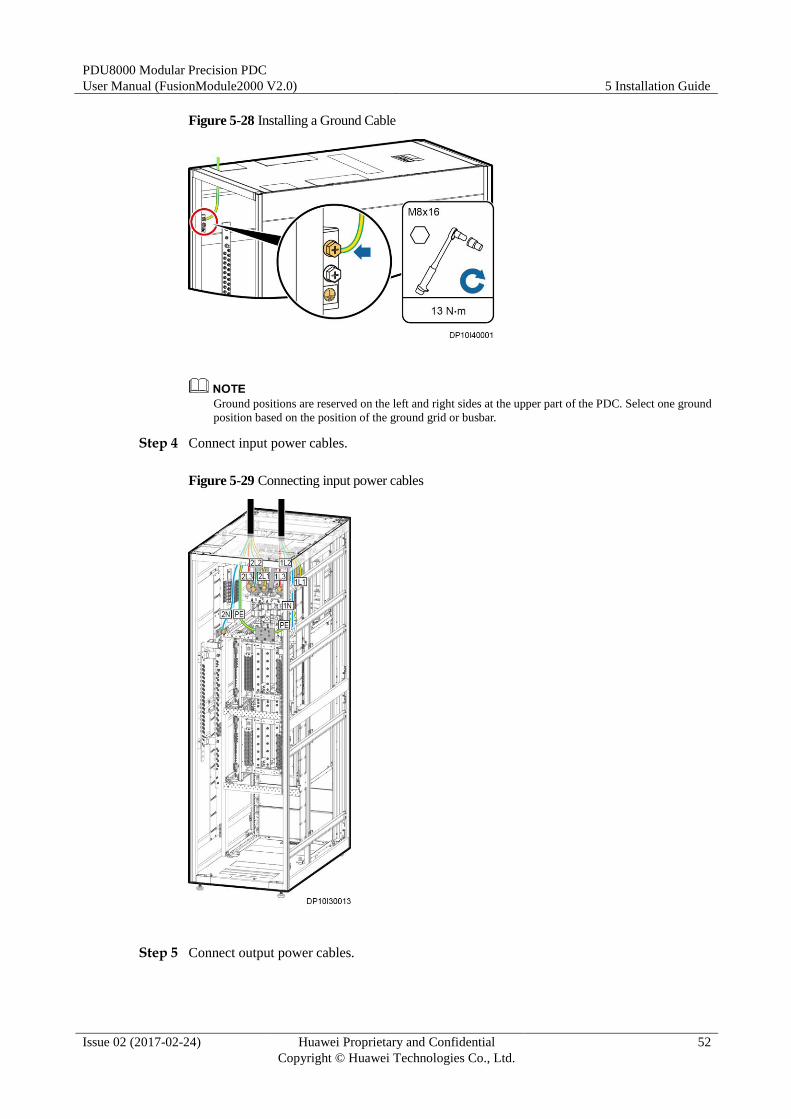
Step 3 Secure one end of the ground cable to the ground bar inside the PDC, and secure the other end
to the ground grid or busbar of the equipment room.
PDU8000 Modular Precision PDC
User Manual (FusionModule2000 V2.0) 5 Installation Guide
Issue 02 (2017-02-24) Huawei Proprietary and Confidential
Copyright © Huawei Technologies Co., Ltd.
52
Figure 5-28 Installing a Ground Cable
Ground positions are reserved on the left and right sides at the upper part of the PDC. Select one ground
position based on the position of the ground grid or busbar.
Step 4 Connect input power cables.
Figure 5-29 Connecting input power cables
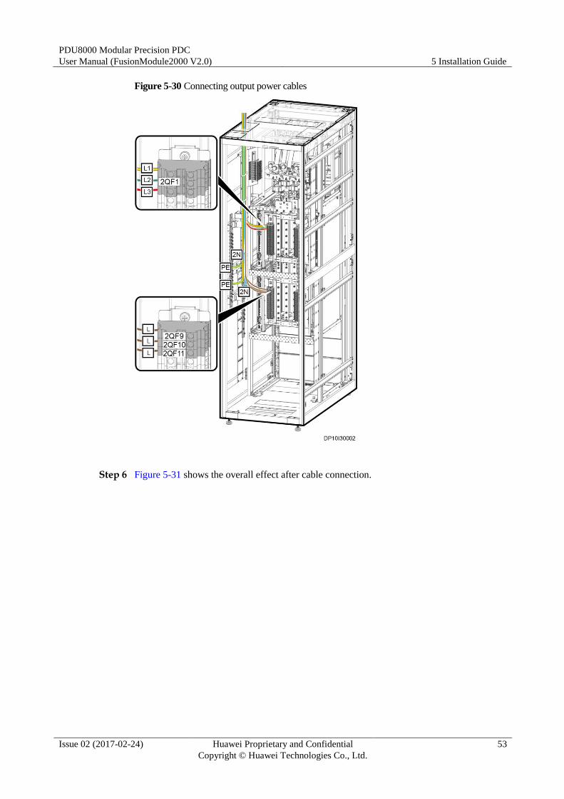
Step 5 Connect output power cables.
PDU8000 Modular Precision PDC
User Manual (FusionModule2000 V2.0) 5 Installation Guide
Issue 02 (2017-02-24) Huawei Proprietary and Confidential
Copyright © Huawei Technologies Co., Ltd.
53
Figure 5-30 Connecting output power cables
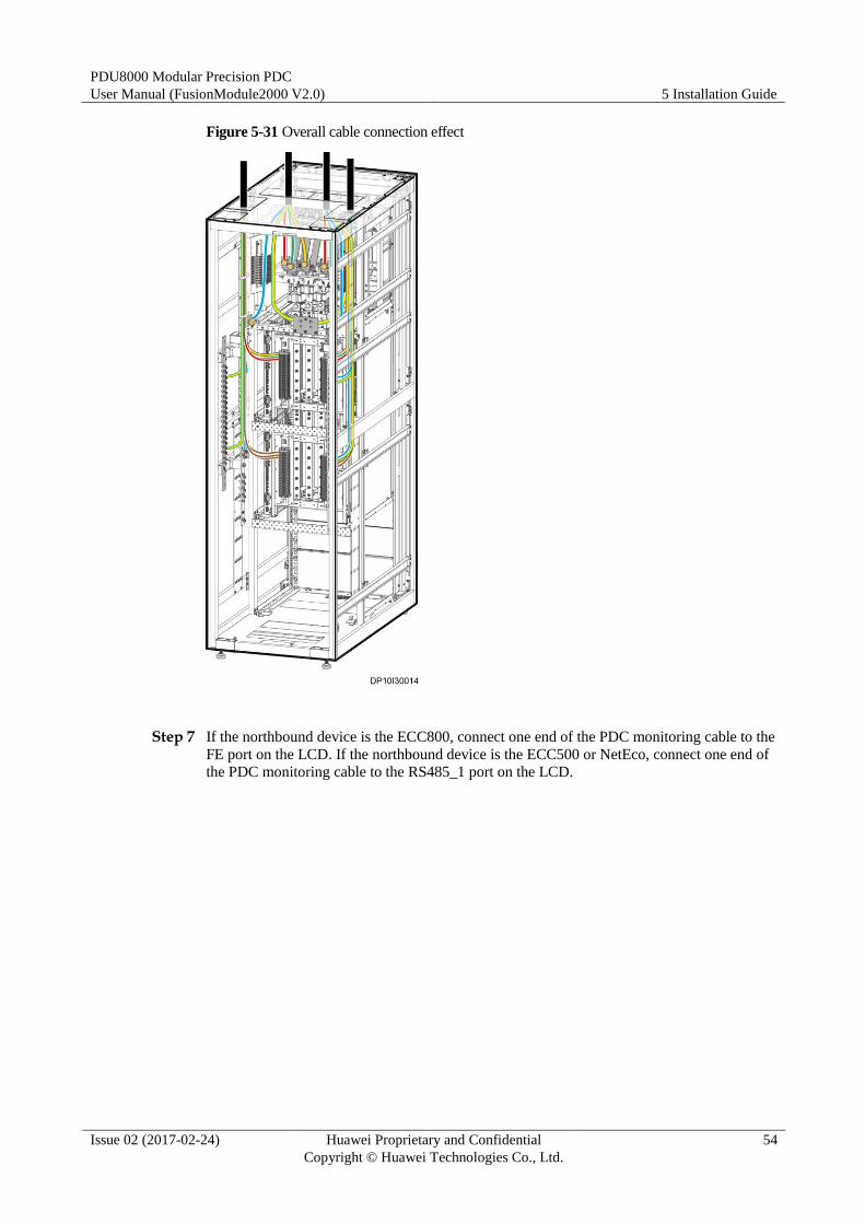
Step 6 Figure 5-31 shows the overall effect after cable connection.
PDU8000 Modular Precision PDC
User Manual (FusionModule2000 V2.0) 5 Installation Guide
Issue 02 (2017-02-24) Huawei Proprietary and Confidential
Copyright © Huawei Technologies Co., Ltd.
54
Figure 5-31 Overall cable connection effect
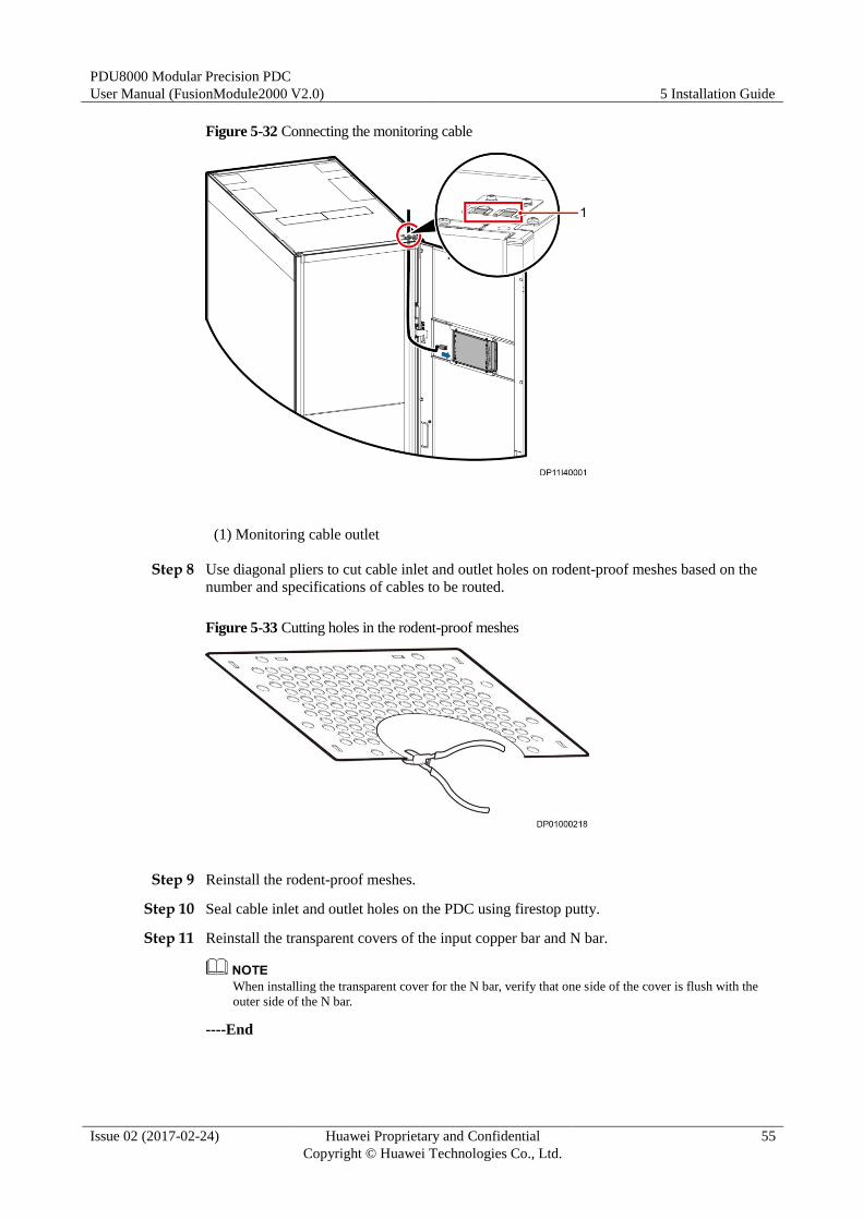
Step 7 If the northbound device is the ECC800, connect one end of the PDC monitoring cable to the
FE port on the LCD. If the northbound device is the ECC500 or NetEco, connect one end of
the PDC monitoring cable to the RS485_1 port on the LCD.
PDU8000 Modular Precision PDC
User Manual (FusionModule2000 V2.0) 5 Installation Guide
Issue 02 (2017-02-24) Huawei Proprietary and Confidential
Copyright © Huawei Technologies Co., Ltd.
55
Figure 5-32 Connecting the monitoring cable
(1) Monitoring cable outlet
Step 8 Use diagonal pliers to cut cable inlet and outlet holes on rodent-proof meshes based on the
number and specifications of cables to be routed.
Figure 5-33 Cutting holes in the rodent-proof meshes
Step 9 Reinstall the rodent-proof meshes.
Step 10 Seal cable inlet and outlet holes on the PDC using firestop putty.
Step 11 Reinstall the transparent covers of the input copper bar and N bar.
When installing the transparent cover for the N bar, verify that one side of the cover is flush with the
outer side of the N bar.
----End
PDU8000 Modular Precision PDC
User Manual (FusionModule2000 V2.0) 6 Commissioning Guide
Issue 02 (2017-02-24) Huawei Proprietary and Confidential
Copyright © Huawei Technologies Co., Ltd.
56
6 Commissioning Guide
6.1 Check Before Power-on Commissioning
Table 6-1 Hardware installation checklist
No. Check Item Result
1 The cabinet is clean and free of dust, dirt, copper cuttings,
and foreign matter.
□Yes □No
2 The paint on the cabinet exterior is intact. □Yes □No
3 The cabinet door and lock work properly. □Yes □No
4 All labels are correct, clear, and complete. □Yes □No
5 The surrounding area of the cabinet contains no waste tape,
cable ties, paper, or packing materials.
□Yes □No
Table 6-2 Electrical connection checklist
No. Check Item Result
1 All cables are connected properly. □Yes □No
2 The ground cable is connected properly. □Yes □No
3 The excessive sections of ground cables and power cables
are cut off.
□Yes □No
4 Phase cables are connected properly. □Yes □No
5 Power cables and ground cables are routed and bundled
separately from other types of cables.
□Yes □No
6 All circuit breakers are OFF. □Yes □No
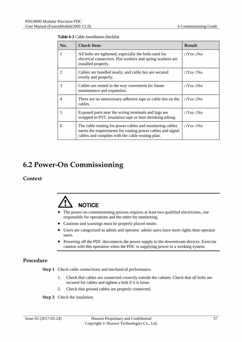
PDU8000 Modular Precision PDC
User Manual (FusionModule2000 V2.0) 6 Commissioning Guide
Issue 02 (2017-02-24) Huawei Proprietary and Confidential
Copyright © Huawei Technologies Co., Ltd.
57
Table 6-3 Cable installation checklist
No. Check Item Result
1 All bolts are tightened, especially the bolts used for
electrical connection. Flat washers and spring washers are
installed properly.
□Yes □No
2 Cables are bundled neatly, and cable ties are secured
evenly and properly.
□Yes □No
3 Cables are routed in the way convenient for future
maintenance and expansion.
□Yes □No
4 There are no unnecessary adhesive tape or cable ties on the
cables.
□Yes □No
5 Exposed parts near the wiring terminals and lugs are
wrapped in PVC insulation tape or heat shrinking tubing.
□Yes □No
6 The cable routing for power cables and monitoring cables
meets the requirements for routing power cables and signal
cables and complies with the cable routing plan.
□Yes □No
6.2 Power-On Commissioning
Context
The power-on commissioning process requires at least two qualified electricians, one
responsible for operations and the other for monitoring.
Cautions and warnings must be properly placed onsite.
Users are categorized as admin and operator. admin users have more rights than operator
users.
Powering off the PDC disconnects the power supply to the downstream devices. Exercise
caution with this operation when the PDC is supplying power to a working system.
Procedure
Step 1 Check cable connections and mechanical performance.
1. Check that cables are connected correctly outside the cabinet. Check that all bolts are
secured for cables and tighten a bolt if it is loose.
2. Check that ground cables are properly connected.
Step 2 Check the insulation.
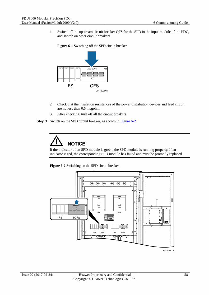
PDU8000 Modular Precision PDC
User Manual (FusionModule2000 V2.0) 6 Commissioning Guide
Issue 02 (2017-02-24) Huawei Proprietary and Confidential
Copyright © Huawei Technologies Co., Ltd.
58
1. Switch off the upstream circuit breaker QFS for the SPD in the input module of the PDC,
and switch on other circuit breakers.
Figure 6-1 Switching off the SPD circuit breaker
2. Check that the insulation resistances of the power distribution devices and feed circuit
are no less than 0.5 megohm.
3. After checking, turn off all the circuit breakers.
Step 3 Switch on the SPD circuit breaker, as shown in Figure 6-2.
If the indicator of an SPD module is green, the SPD module is running properly. If an
indicator is red, the corresponding SPD module has failed and must be promptly replaced.
Figure 6-2 Switching on the SPD circuit breaker
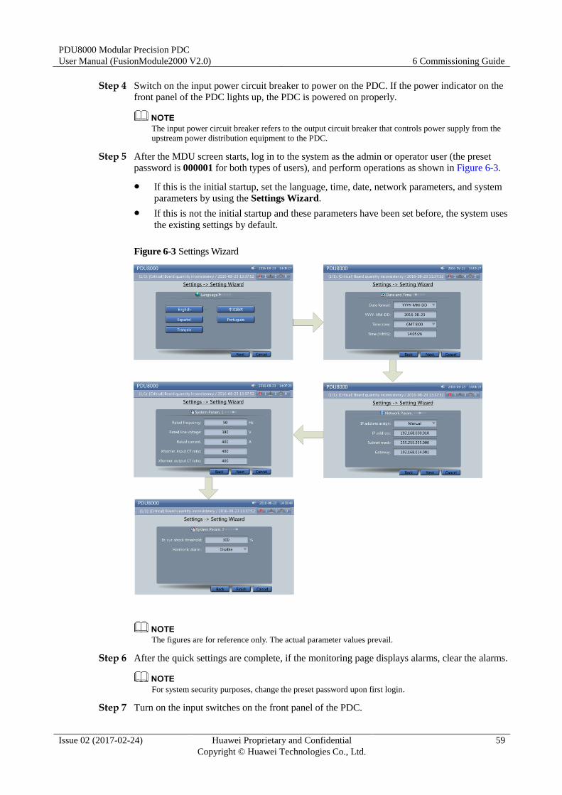
PDU8000 Modular Precision PDC
User Manual (FusionModule2000 V2.0) 6 Commissioning Guide
Issue 02 (2017-02-24) Huawei Proprietary and Confidential
Copyright © Huawei Technologies Co., Ltd.
59
Step 4 Switch on the input power circuit breaker to power on the PDC. If the power indicator on the
front panel of the PDC lights up, the PDC is powered on properly.
The input power circuit breaker refers to the output circuit breaker that controls power supply from the
upstream power distribution equipment to the PDC.
Step 5 After the MDU screen starts, log in to the system as the admin or operator user (the preset
password is 000001 for both types of users), and perform operations as shown in Figure 6-3.
If this is the initial startup, set the language, time, date, network parameters, and system
parameters by using the Settings Wizard.
If this is not the initial startup and these parameters have been set before, the system uses
the existing settings by default.
Figure 6-3 Settings Wizard
The figures are for reference only. The actual parameter values prevail.
Step 6 After the quick settings are complete, if the monitoring page displays alarms, clear the alarms.
For system security purposes, change the preset password upon first login.
Step 7 Turn on the input switches on the front panel of the PDC.
PDU8000 Modular Precision PDC
User Manual (FusionModule2000 V2.0) 6 Commissioning Guide
Issue 02 (2017-02-24) Huawei Proprietary and Confidential
Copyright © Huawei Technologies Co., Ltd.
60
Step 8 Switch on the output circuit breakers except reserved circuit breakers in the PDC in sequence
to power on the corresponding devices and check whether the monitoring parameters on the
MDU screen are correct.
Step 9 (Optional) Power off the PDC.
1. Turn off the output switches in the PDC.
2. Turn off the input switches in the PDC.
3. Turn off the input power circuit breaker.
----End
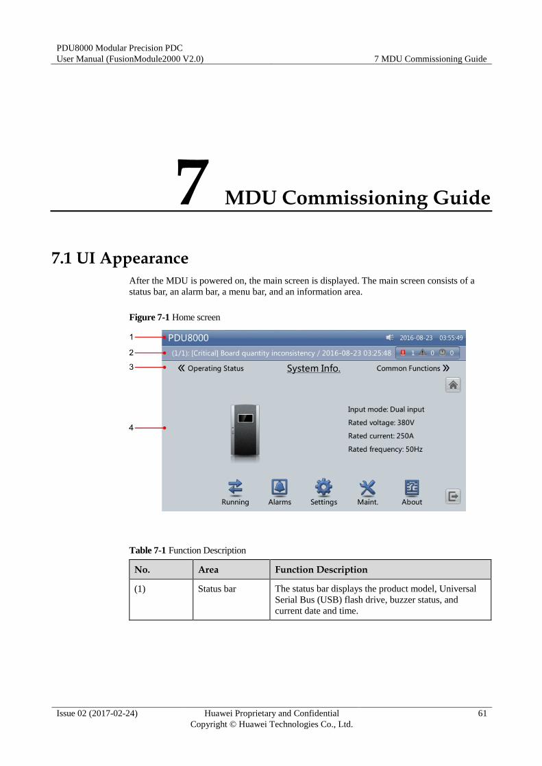
PDU8000 Modular Precision PDC
User Manual (FusionModule2000 V2.0) 7 MDU Commissioning Guide
Issue 02 (2017-02-24) Huawei Proprietary and Confidential
Copyright © Huawei Technologies Co., Ltd.
61
7 MDU Commissioning Guide
7.1 UI Appearance
After the MDU is powered on, the main screen is displayed. The main screen consists of a
status bar, an alarm bar, a menu bar, and an information area.
Figure 7-1 Home screen
Table 7-1 Function Description
No. Area Function Description
(1) Status bar The status bar displays the product model, Universal
Serial Bus (USB) flash drive, buzzer status, and
current date and time.

PDU8000 Modular Precision PDC
User Manual (FusionModule2000 V2.0) 7 MDU Commissioning Guide
Issue 02 (2017-02-24) Huawei Proprietary and Confidential
Copyright © Huawei Technologies Co., Ltd.
62
No. Area Function Description
(2) Alarm bar The alarm bar displays active alarms in a scrolling
manner and the numbers of active critical alarms,
major alarms, and warnings. You can click
to enter the Active
Alarm screen.
(3) Menu bar The menu bar displays Common Functions, System
Info., and Operating Status.
(4) Information
window
Table 7-2 lists the functions of common buttons in the
information window.
Table 7-2 Functions of common buttons in the information window
Button Function Description
Returns to the upper-level menu.
Goes to the previous screen.
Goes to the next screen.
Returns to the main menu screen.
Logs out.
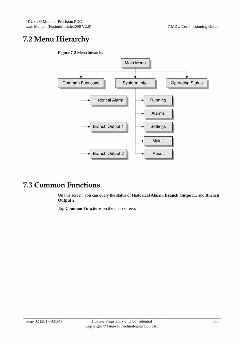
PDU8000 Modular Precision PDC
User Manual (FusionModule2000 V2.0) 7 MDU Commissioning Guide
Issue 02 (2017-02-24) Huawei Proprietary and Confidential
Copyright © Huawei Technologies Co., Ltd.
63
7.2 Menu Hierarchy
Figure 7-2 Menu hierarchy
7.3 Common Functions
On this screen, you can query the status of Historical Alarm, Branch Output 1, and Branch
Output 2.
Tap Common Functions on the main screen.
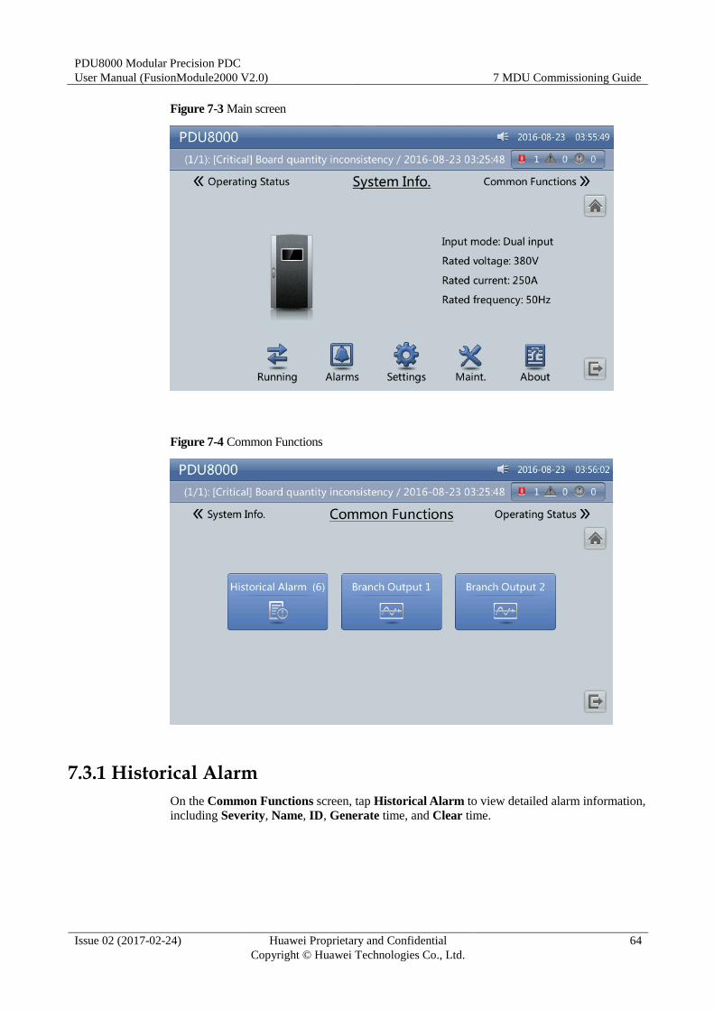
PDU8000 Modular Precision PDC
User Manual (FusionModule2000 V2.0) 7 MDU Commissioning Guide
Issue 02 (2017-02-24) Huawei Proprietary and Confidential
Copyright © Huawei Technologies Co., Ltd.
64
Figure 7-3 Main screen
Figure 7-4 Common Functions
7.3.1 Historical Alarm
On the Common Functions screen, tap Historical Alarm to view detailed alarm information,
including Severity, Name, ID, Generate time, and Clear time.
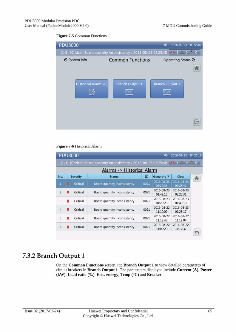
PDU8000 Modular Precision PDC
User Manual (FusionModule2000 V2.0) 7 MDU Commissioning Guide
Issue 02 (2017-02-24) Huawei Proprietary and Confidential
Copyright © Huawei Technologies Co., Ltd.
65
Figure 7-5 Common Functions
Figure 7-6 Historical Alarm
7.3.2 Branch Output 1
On the Common Functions screen, tap Branch Output 1 to view detailed parameters of
circuit breakers in Branch Output 1. The parameters displayed include Current (A), Power
(kW), Load ratio (%), Elec. energy, Temp (°C) and Breaker.
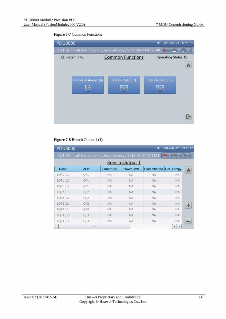
PDU8000 Modular Precision PDC
User Manual (FusionModule2000 V2.0) 7 MDU Commissioning Guide
Issue 02 (2017-02-24) Huawei Proprietary and Confidential
Copyright © Huawei Technologies Co., Ltd.
66
Figure 7-7 Common Functions
Figure 7-8 Branch Output 1 (1)
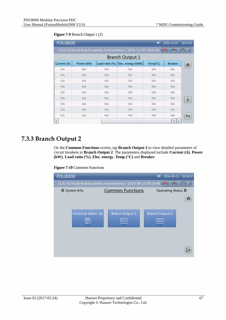
PDU8000 Modular Precision PDC
User Manual (FusionModule2000 V2.0) 7 MDU Commissioning Guide
Issue 02 (2017-02-24) Huawei Proprietary and Confidential
Copyright © Huawei Technologies Co., Ltd.
67
Figure 7-9 Branch Output 1 (2)
7.3.3 Branch Output 2
On the Common Functions screen, tap Branch Output 2 to view detailed parameters of
circuit breakers in Branch Output 2. The parameters displayed include Current (A), Power
(kW), Load ratio (%), Elec. energy, Temp (°C) and Breaker.
Figure 7-10 Common Functions
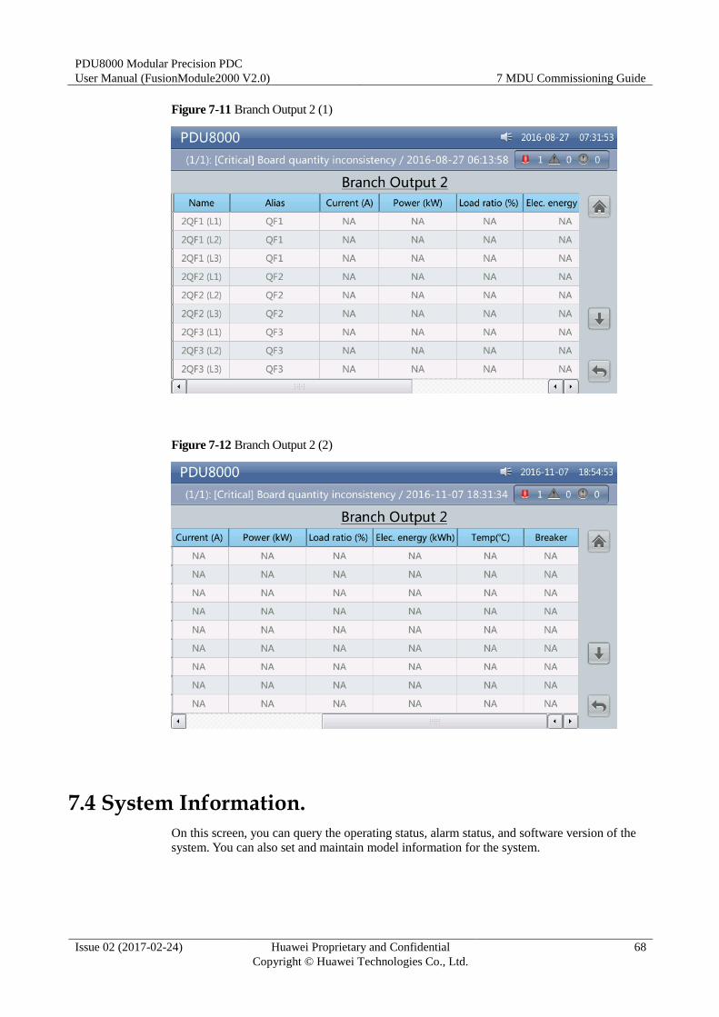
PDU8000 Modular Precision PDC
User Manual (FusionModule2000 V2.0) 7 MDU Commissioning Guide
Issue 02 (2017-02-24) Huawei Proprietary and Confidential
Copyright © Huawei Technologies Co., Ltd.
68
Figure 7-11 Branch Output 2 (1)
Figure 7-12 Branch Output 2 (2)
7.4 System Information.
On this screen, you can query the operating status, alarm status, and software version of the
system. You can also set and maintain model information for the system.
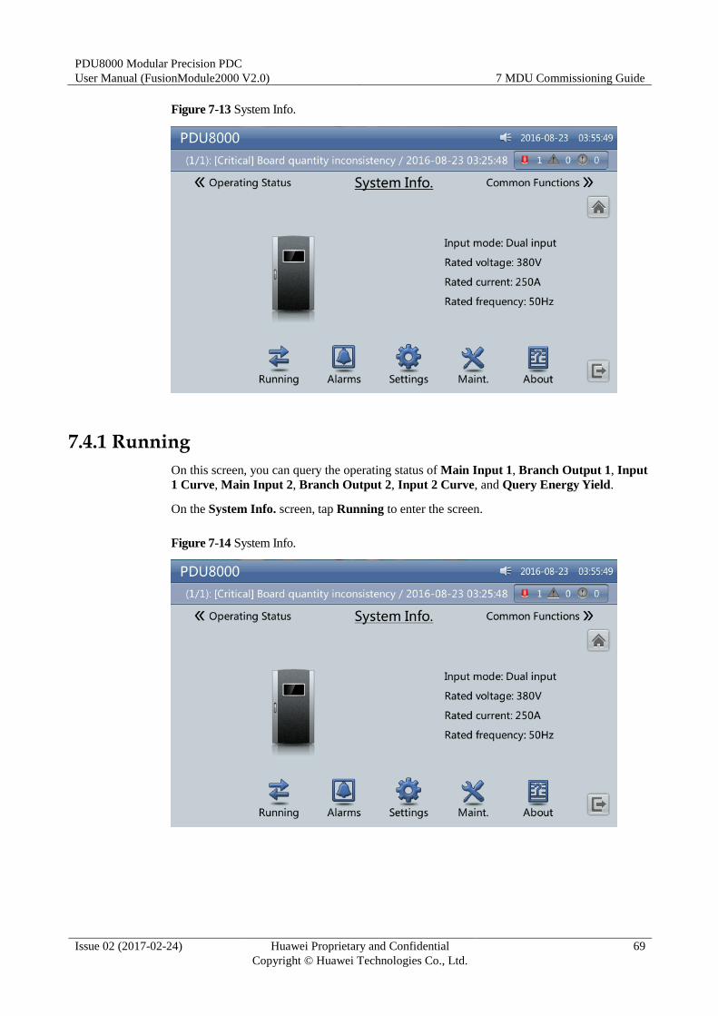
PDU8000 Modular Precision PDC
User Manual (FusionModule2000 V2.0) 7 MDU Commissioning Guide
Issue 02 (2017-02-24) Huawei Proprietary and Confidential
Copyright © Huawei Technologies Co., Ltd.
69
Figure 7-13 System Info.
7.4.1 Running
On this screen, you can query the operating status of Main Input 1, Branch Output 1, Input
1 Curve, Main Input 2, Branch Output 2, Input 2 Curve, and Query Energy Yield.
On the System Info. screen, tap Running to enter the screen.
Figure 7-14 System Info.
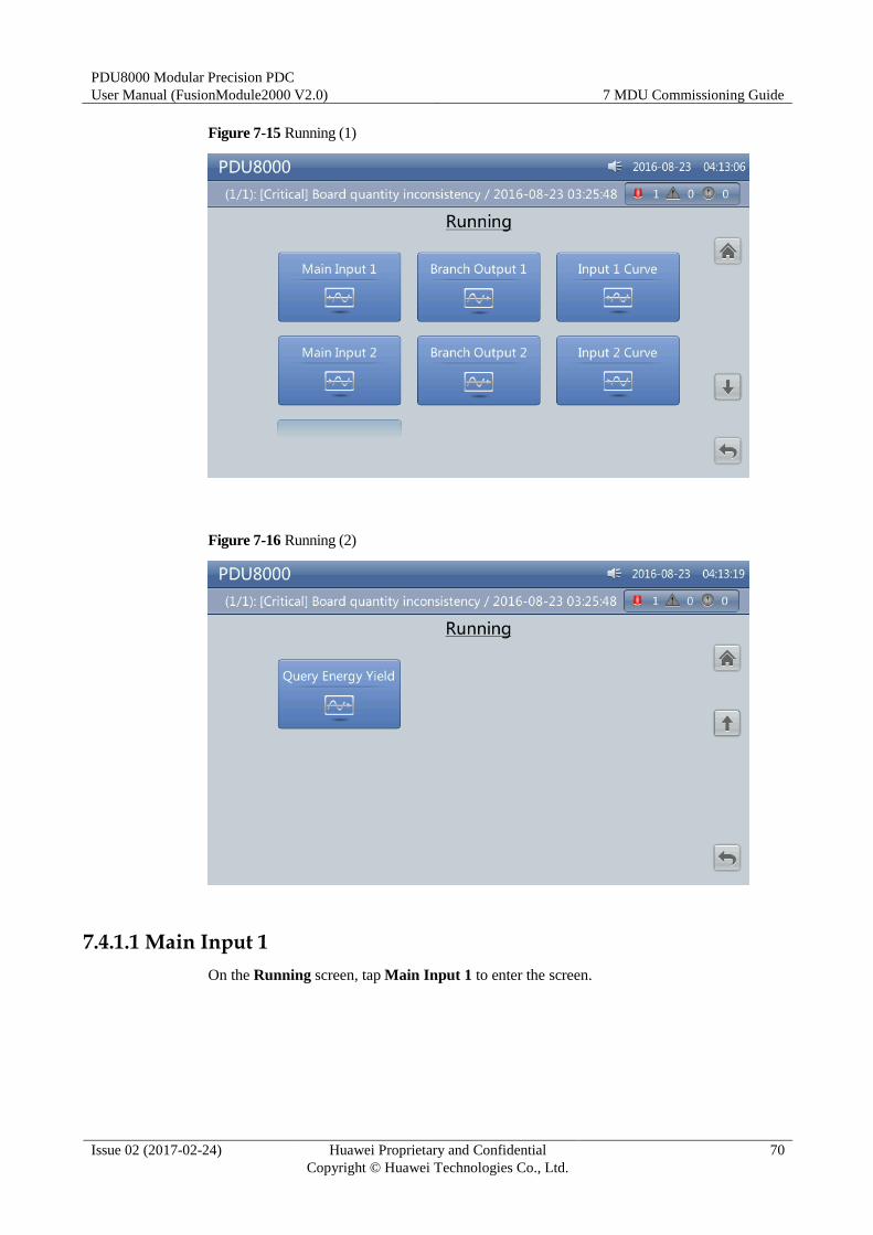
PDU8000 Modular Precision PDC
User Manual (FusionModule2000 V2.0) 7 MDU Commissioning Guide
Issue 02 (2017-02-24) Huawei Proprietary and Confidential
Copyright © Huawei Technologies Co., Ltd.
70
Figure 7-15 Running (1)
Figure 7-16 Running (2)
7.4.1.1 Main Input 1
On the Running screen, tap Main Input 1 to enter the screen.
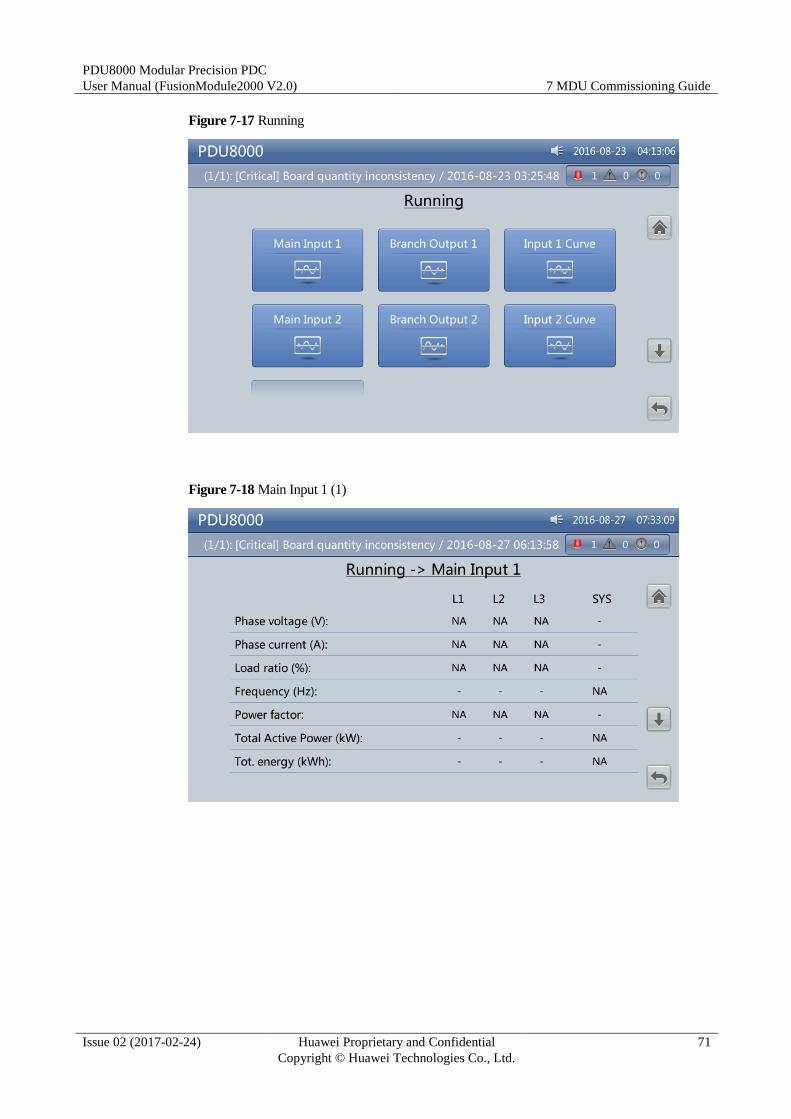
PDU8000 Modular Precision PDC
User Manual (FusionModule2000 V2.0) 7 MDU Commissioning Guide
Issue 02 (2017-02-24) Huawei Proprietary and Confidential
Copyright © Huawei Technologies Co., Ltd.
71
Figure 7-17 Running
Figure 7-18 Main Input 1 (1)
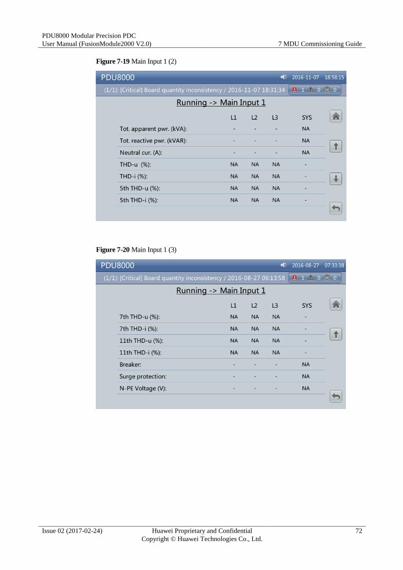
PDU8000 Modular Precision PDC
User Manual (FusionModule2000 V2.0) 7 MDU Commissioning Guide
Issue 02 (2017-02-24) Huawei Proprietary and Confidential
Copyright © Huawei Technologies Co., Ltd.
72
Figure 7-19 Main Input 1 (2)
Figure 7-20 Main Input 1 (3)

PDU8000 Modular Precision PDC
User Manual (FusionModule2000 V2.0) 7 MDU Commissioning Guide
Issue 02 (2017-02-24) Huawei Proprietary and Confidential
Copyright © Huawei Technologies Co., Ltd.
73
Figure 7-21 Main Input 1 (4)
Power factor
Indicates the proportion of passive power to apparent power.
Phase voltage (V)/Phase current (A)/Frequency (Hz)
Indicates the mains input phase voltage, mains input phase current, and mains input
frequency.
Load ratio (%)
Indicates the load ratio of each phase, that is, ratio of actual power to rated power.
Total Active Power (kW)
Indicates the sum of active power of all phases of the mains input.
Tot. energy (kWh)
Indicates the sum of electricity energy of all phases of the mains input.
Tot. apparent pwr. (kVA)
Indicates the sum of apparent power of all phases of the mains input.
Tot. reactive pwr. (kVAR)
Indicates the sum of reactive power of all phases of the mains input.
Temp (°C)
Temperature on the main route of the PDC.
7.4.1.2 Branch Output 1
On the Running screen, tap Branch Output 1 to view detailed parameters of Branch
Output 1. The parameters displayed include Current (A), Power (kW), Load ratio (%), Elec. energy, Temp (°C) and Breaker.

PDU8000 Modular Precision PDC
User Manual (FusionModule2000 V2.0) 7 MDU Commissioning Guide
Issue 02 (2017-02-24) Huawei Proprietary and Confidential
Copyright © Huawei Technologies Co., Ltd.
74
Figure 7-22 Running
Figure 7-23 Branch Output 1 (1)
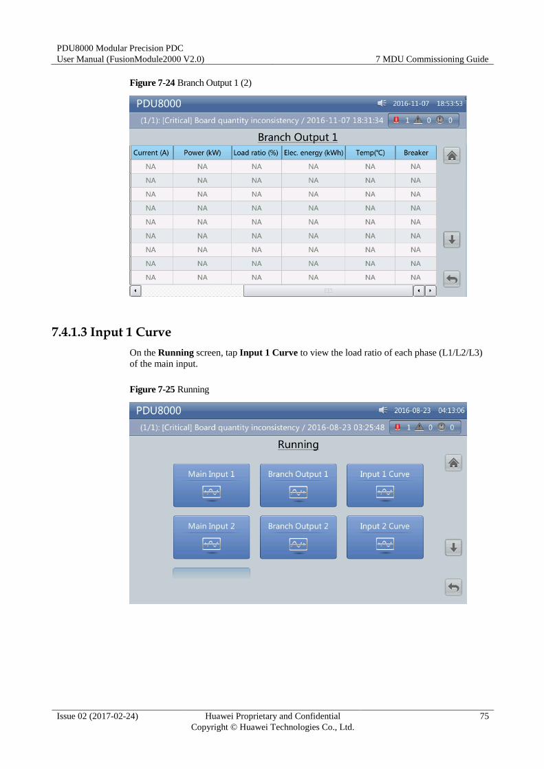
PDU8000 Modular Precision PDC
User Manual (FusionModule2000 V2.0) 7 MDU Commissioning Guide
Issue 02 (2017-02-24) Huawei Proprietary and Confidential
Copyright © Huawei Technologies Co., Ltd.
75
Figure 7-24 Branch Output 1 (2)
7.4.1.3 Input 1 Curve
On the Running screen, tap Input 1 Curve to view the load ratio of each phase (L1/L2/L3)
of the main input.
Figure 7-25 Running
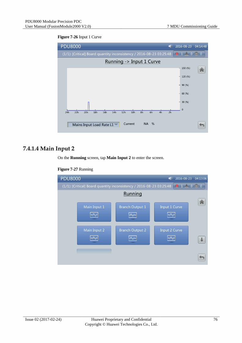
PDU8000 Modular Precision PDC
User Manual (FusionModule2000 V2.0) 7 MDU Commissioning Guide
Issue 02 (2017-02-24) Huawei Proprietary and Confidential
Copyright © Huawei Technologies Co., Ltd.
76
Figure 7-26 Input 1 Curve
7.4.1.4 Main Input 2
On the Running screen, tap Main Input 2 to enter the screen.
Figure 7-27 Running
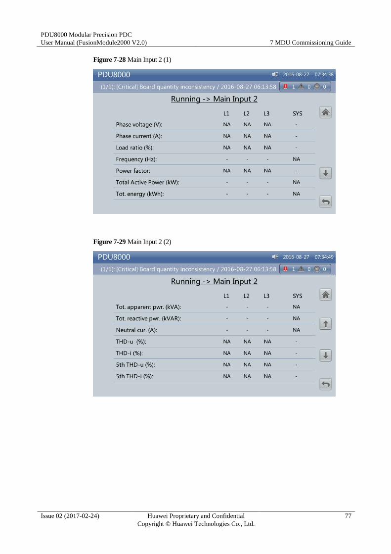
PDU8000 Modular Precision PDC
User Manual (FusionModule2000 V2.0) 7 MDU Commissioning Guide
Issue 02 (2017-02-24) Huawei Proprietary and Confidential
Copyright © Huawei Technologies Co., Ltd.
77
Figure 7-28 Main Input 2 (1)
Figure 7-29 Main Input 2 (2)
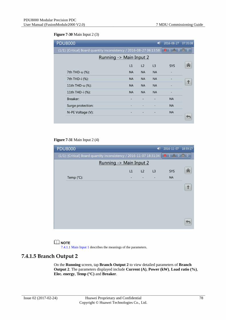
PDU8000 Modular Precision PDC
User Manual (FusionModule2000 V2.0) 7 MDU Commissioning Guide
Issue 02 (2017-02-24) Huawei Proprietary and Confidential
Copyright © Huawei Technologies Co., Ltd.
78
Figure 7-30 Main Input 2 (3)
Figure 7-31 Main Input 2 (4)
7.4.1.1 Main Input 1 describes the meanings of the parameters.
7.4.1.5 Branch Output 2
On the Running screen, tap Branch Output 2 to view detailed parameters of Branch
Output 2. The parameters displayed include Current (A), Power (kW), Load ratio (%),
Elec. energy, Temp (°C) and Breaker.
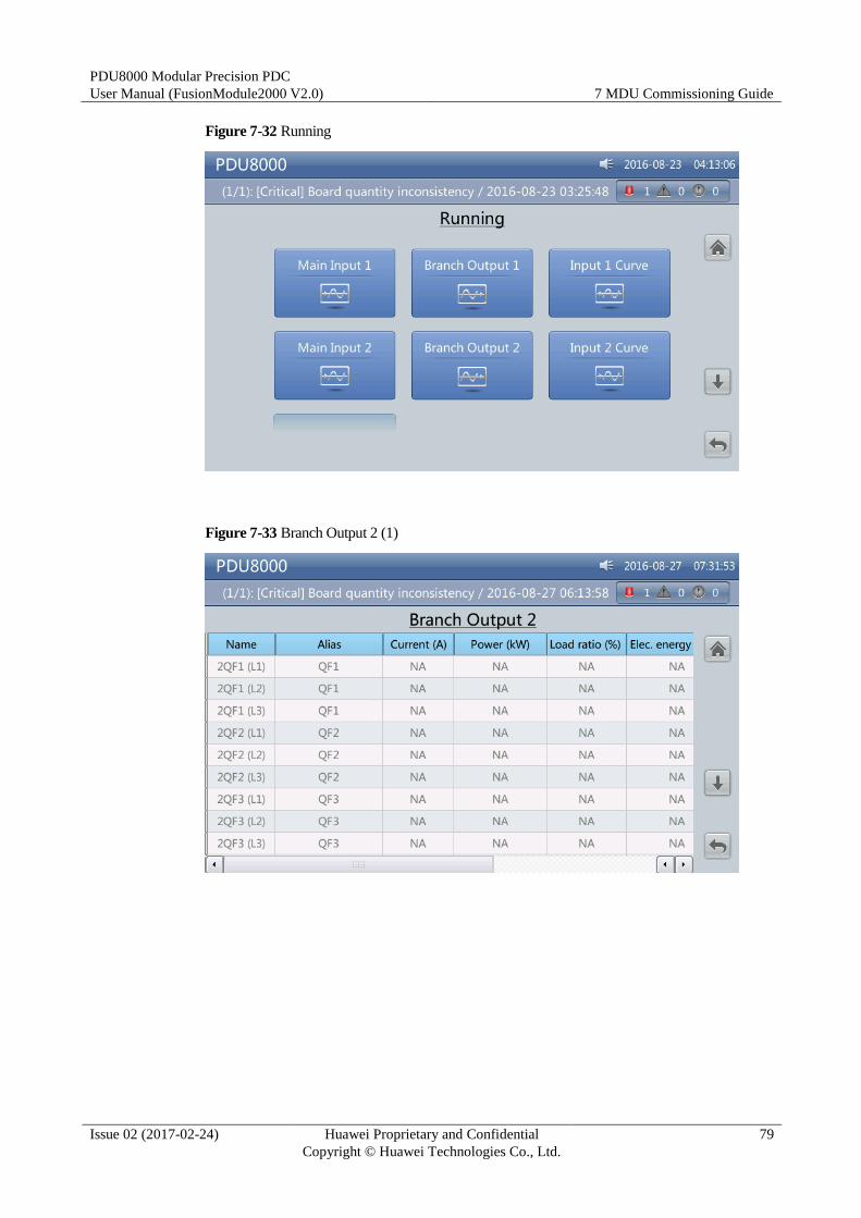
PDU8000 Modular Precision PDC
User Manual (FusionModule2000 V2.0) 7 MDU Commissioning Guide
Issue 02 (2017-02-24) Huawei Proprietary and Confidential
Copyright © Huawei Technologies Co., Ltd.
79
Figure 7-32 Running
Figure 7-33 Branch Output 2 (1)
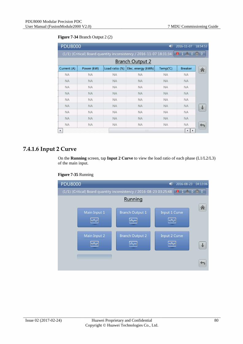
PDU8000 Modular Precision PDC
User Manual (FusionModule2000 V2.0) 7 MDU Commissioning Guide
Issue 02 (2017-02-24) Huawei Proprietary and Confidential
Copyright © Huawei Technologies Co., Ltd.
80
Figure 7-34 Branch Output 2 (2)
7.4.1.6 Input 2 Curve
On the Running screen, tap Input 2 Curve to view the load ratio of each phase (L1/L2/L3)
of the main input.
Figure 7-35 Running
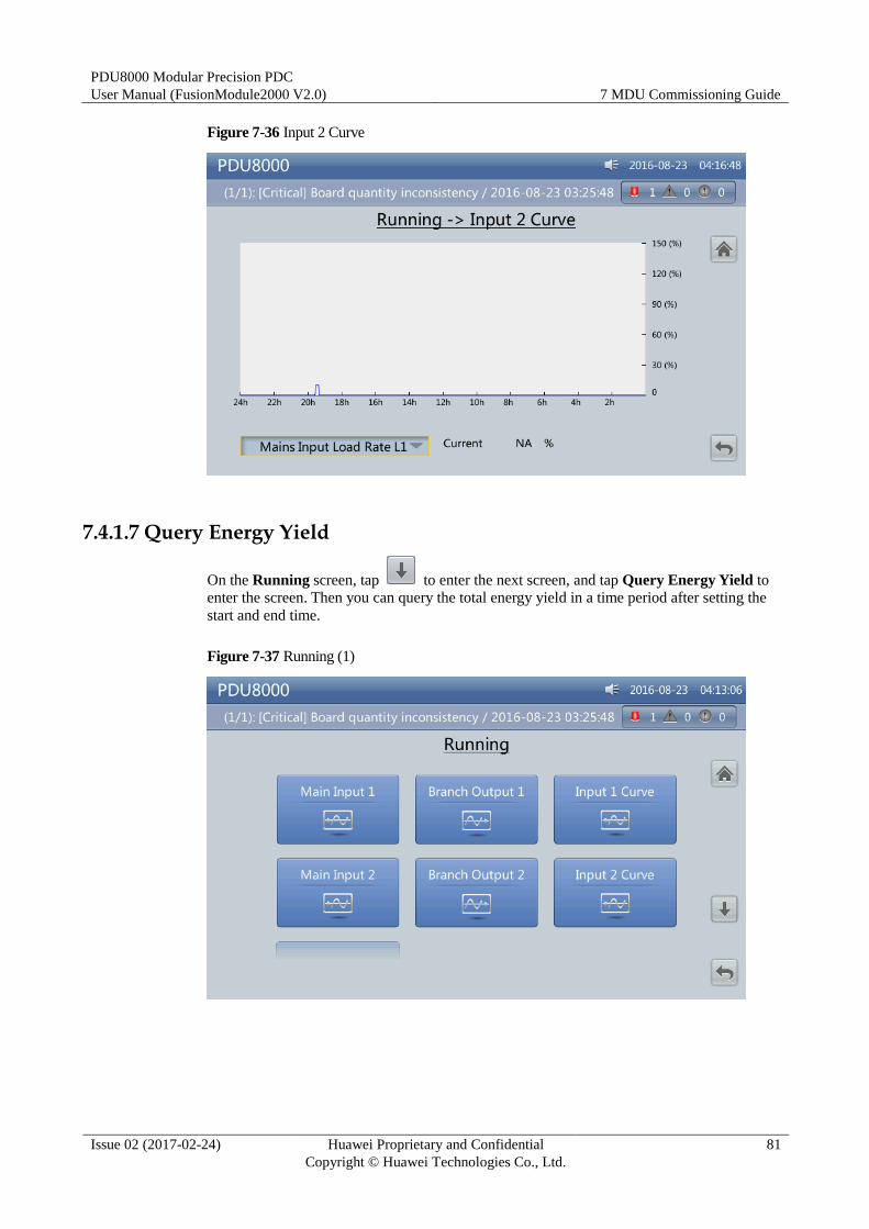
PDU8000 Modular Precision PDC
User Manual (FusionModule2000 V2.0) 7 MDU Commissioning Guide
Issue 02 (2017-02-24) Huawei Proprietary and Confidential
Copyright © Huawei Technologies Co., Ltd.
81
Figure 7-36 Input 2 Curve
7.4.1.7 Query Energy Yield
On the Running screen, tap to enter the next screen, and tap Query Energy Yield to
enter the screen. Then you can query the total energy yield in a time period after setting the
start and end time.
Figure 7-37 Running (1)
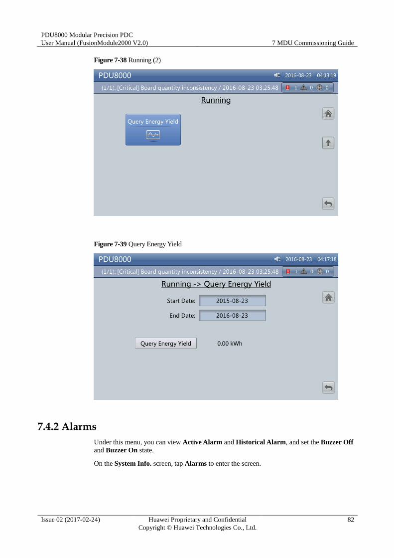
PDU8000 Modular Precision PDC
User Manual (FusionModule2000 V2.0) 7 MDU Commissioning Guide
Issue 02 (2017-02-24) Huawei Proprietary and Confidential
Copyright © Huawei Technologies Co., Ltd.
82
Figure 7-38 Running (2)
Figure 7-39 Query Energy Yield
7.4.2 Alarms
Under this menu, you can view Active Alarm and Historical Alarm, and set the Buzzer Off
and Buzzer On state.
On the System Info. screen, tap Alarms to enter the screen.
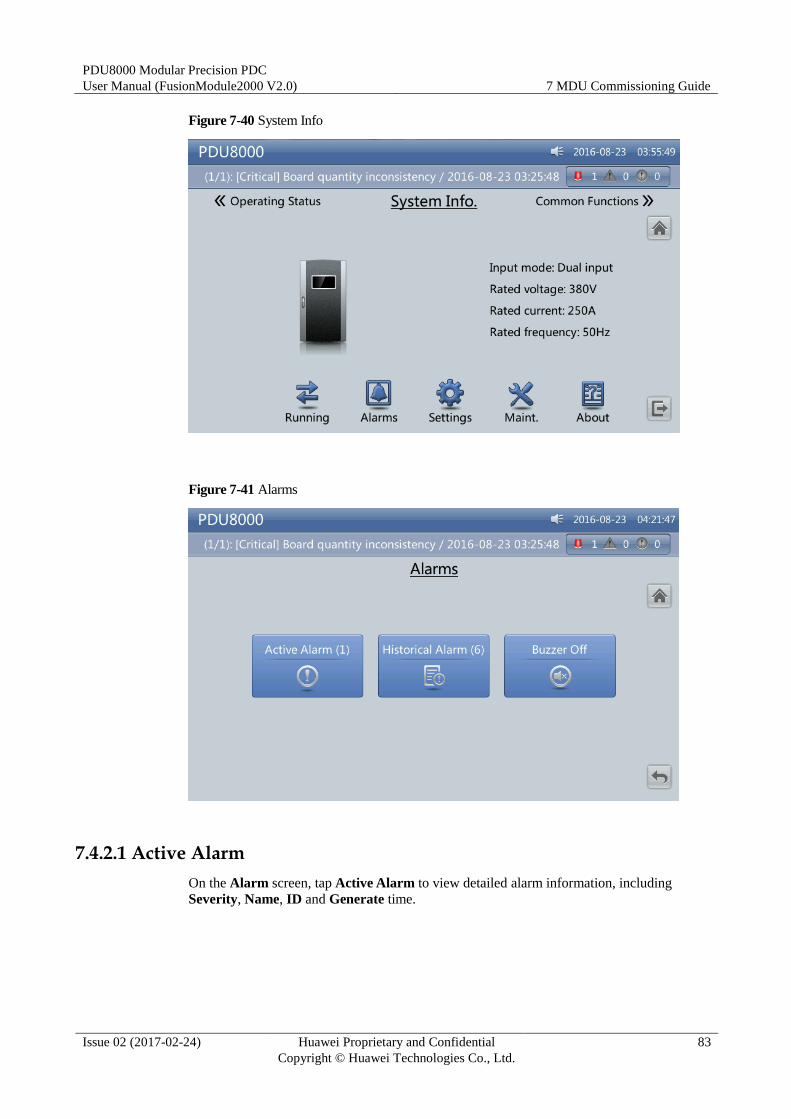
PDU8000 Modular Precision PDC
User Manual (FusionModule2000 V2.0) 7 MDU Commissioning Guide
Issue 02 (2017-02-24) Huawei Proprietary and Confidential
Copyright © Huawei Technologies Co., Ltd.
83
Figure 7-40 System Info
Figure 7-41 Alarms
7.4.2.1 Active Alarm
On the Alarm screen, tap Active Alarm to view detailed alarm information, including
Severity, Name, ID and Generate time.
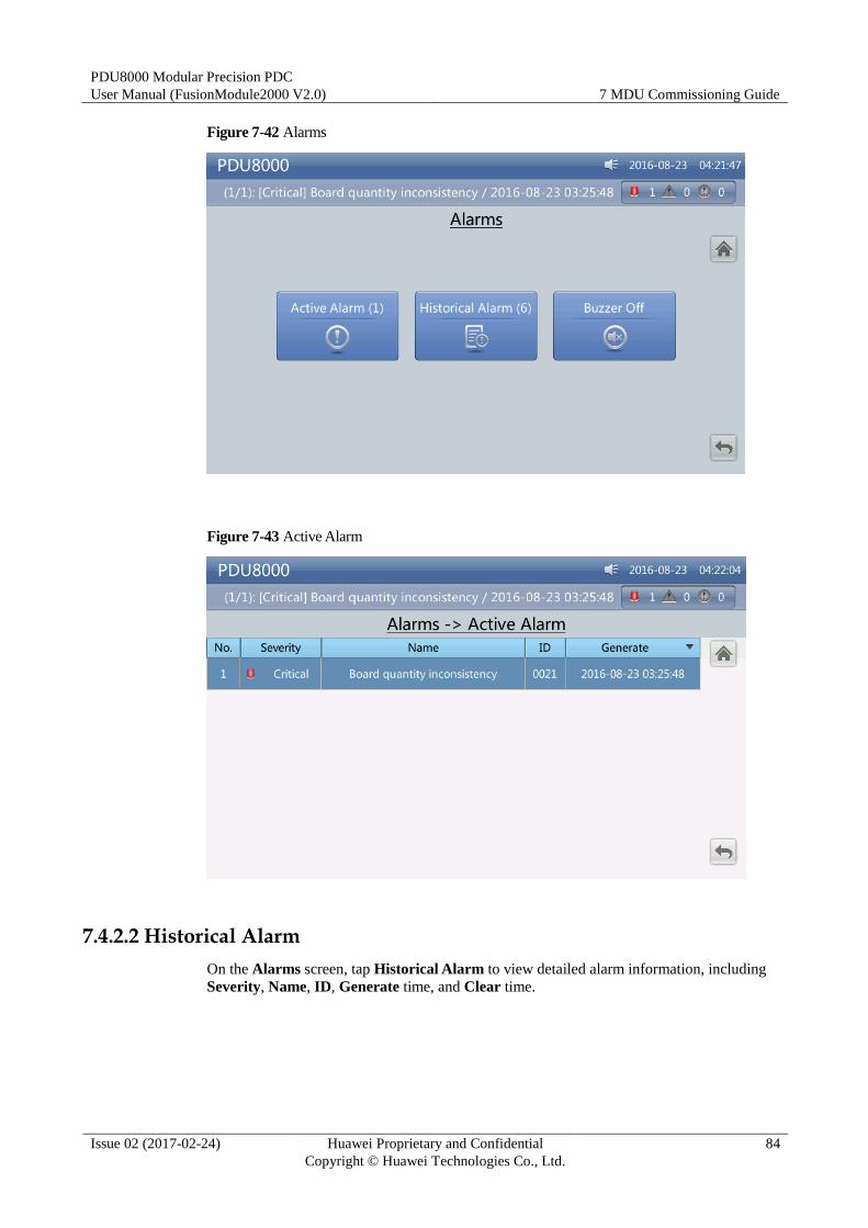
PDU8000 Modular Precision PDC
User Manual (FusionModule2000 V2.0) 7 MDU Commissioning Guide
Issue 02 (2017-02-24) Huawei Proprietary and Confidential
Copyright © Huawei Technologies Co., Ltd.
84
Figure 7-42 Alarms
Figure 7-43 Active Alarm
7.4.2.2 Historical Alarm
On the Alarms screen, tap Historical Alarm to view detailed alarm information, including
Severity, Name, ID, Generate time, and Clear time.

PDU8000 Modular Precision PDC
User Manual (FusionModule2000 V2.0) 7 MDU Commissioning Guide
Issue 02 (2017-02-24) Huawei Proprietary and Confidential
Copyright © Huawei Technologies Co., Ltd.
85
Figure 7-44 Alarms
Figure 7-45 Historical Alarm
7.4.2.3 Buzzer Off
Two buzzer control items are available, that is, Buzzer On and Buzzer Off. If the buzzer of
the system is in the Buzzer Off state, Buzzer On is displayed on the operation screen. If the
buzzer of the system is in the Buzzer On state, Buzzer Off is displayed on the operation
screen.
On the Alarms screen, tap Buzzer Off, and tap OK on the screen that appears.
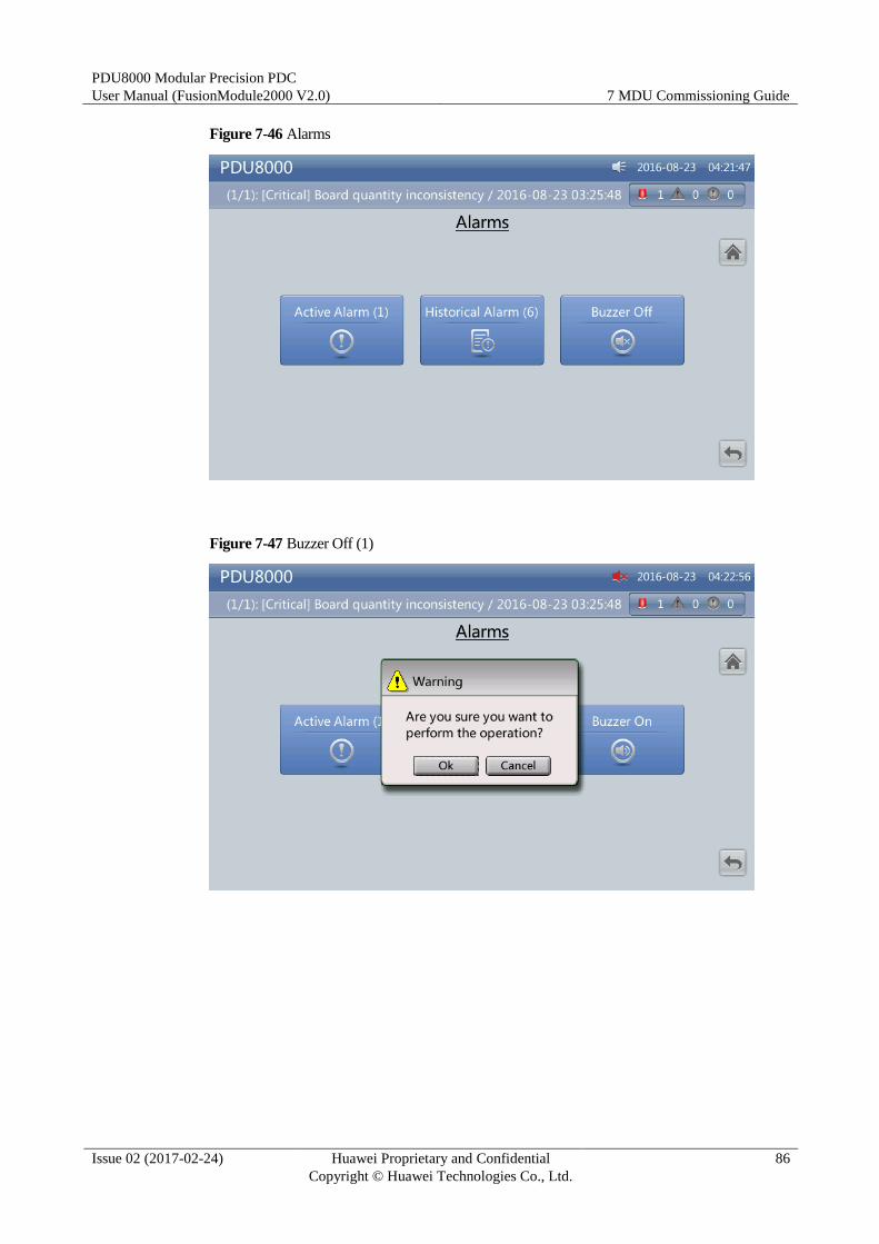
PDU8000 Modular Precision PDC
User Manual (FusionModule2000 V2.0) 7 MDU Commissioning Guide
Issue 02 (2017-02-24) Huawei Proprietary and Confidential
Copyright © Huawei Technologies Co., Ltd.
86
Figure 7-46 Alarms
Figure 7-47 Buzzer Off (1)
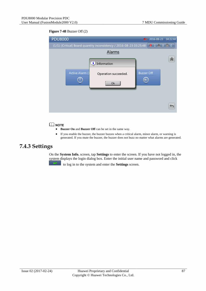
PDU8000 Modular Precision PDC
User Manual (FusionModule2000 V2.0) 7 MDU Commissioning Guide
Issue 02 (2017-02-24) Huawei Proprietary and Confidential
Copyright © Huawei Technologies Co., Ltd.
87
Figure 7-48 Buzzer Off (2)
Buzzer On and Buzzer Off can be set in the same way.
If you enable the buzzer, the buzzer buzzes when a critical alarm, minor alarm, or warning is
generated. If you mute the buzzer, the buzzer does not buzz no matter what alarms are generated.
7.4.3 Settings
On the System Info. screen, tap Settings to enter the screen. If you have not logged in, the
system displays the login dialog box. Enter the initial user name and password and click
to log in to the system and enter the Settings screen.
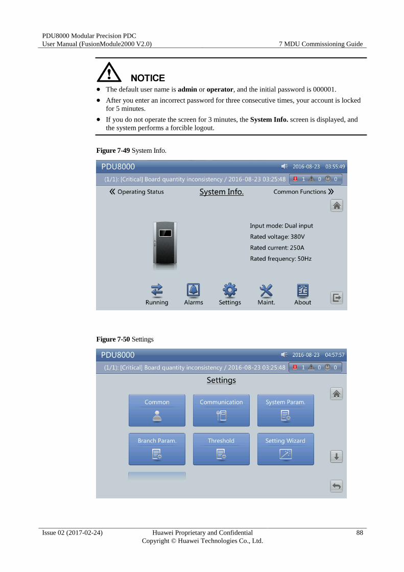
PDU8000 Modular Precision PDC
User Manual (FusionModule2000 V2.0) 7 MDU Commissioning Guide
Issue 02 (2017-02-24) Huawei Proprietary and Confidential
Copyright © Huawei Technologies Co., Ltd.
88
The default user name is admin or operator, and the initial password is 000001.
After you enter an incorrect password for three consecutive times, your account is locked
for 5 minutes.
If you do not operate the screen for 3 minutes, the System Info. screen is displayed, and
the system performs a forcible logout.
Figure 7-49 System Info.
Figure 7-50 Settings
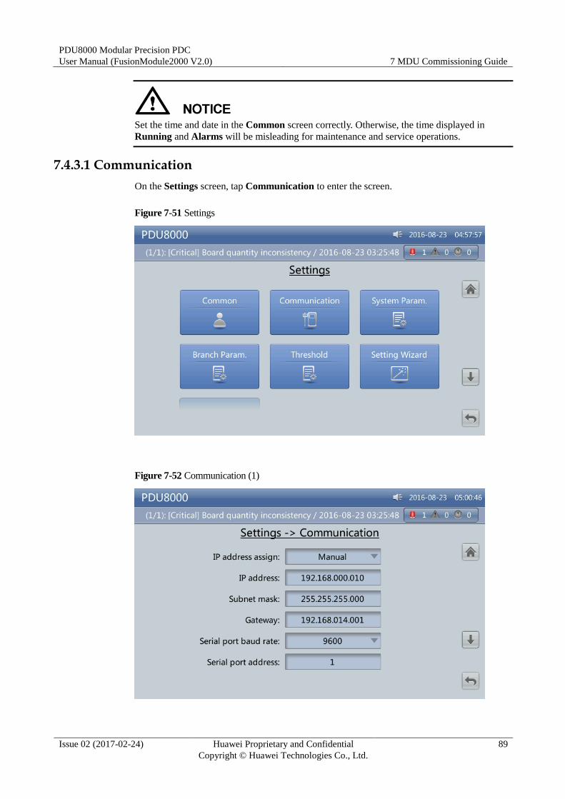
PDU8000 Modular Precision PDC
User Manual (FusionModule2000 V2.0) 7 MDU Commissioning Guide
Issue 02 (2017-02-24) Huawei Proprietary and Confidential
Copyright © Huawei Technologies Co., Ltd.
89
Set the time and date in the Common screen correctly. Otherwise, the time displayed in
Running and Alarms will be misleading for maintenance and service operations.
7.4.3.1 Communication
On the Settings screen, tap Communication to enter the screen.
Figure 7-51 Settings
Figure 7-52 Communication (1)
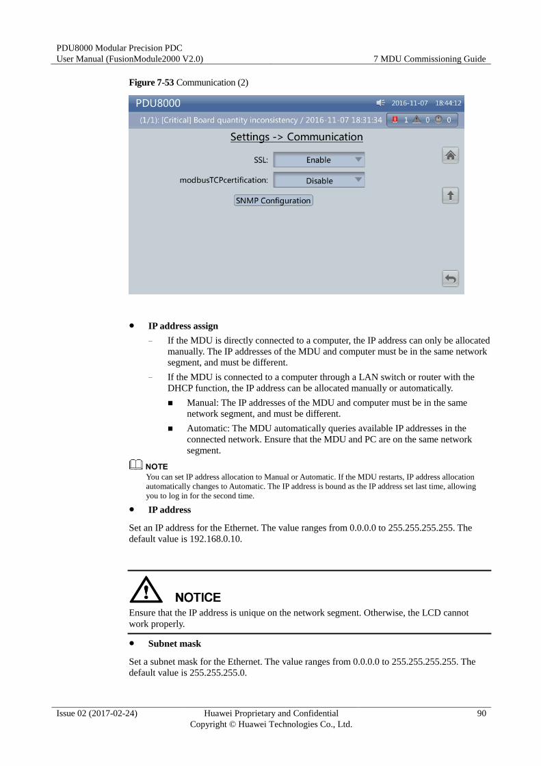
PDU8000 Modular Precision PDC
User Manual (FusionModule2000 V2.0) 7 MDU Commissioning Guide
Issue 02 (2017-02-24) Huawei Proprietary and Confidential
Copyright © Huawei Technologies Co., Ltd.
90
Figure 7-53 Communication (2)
IP address assign
− If the MDU is directly connected to a computer, the IP address can only be allocated
manually. The IP addresses of the MDU and computer must be in the same network
segment, and must be different.
− If the MDU is connected to a computer through a LAN switch or router with the
DHCP function, the IP address can be allocated manually or automatically.
Manual: The IP addresses of the MDU and computer must be in the same
network segment, and must be different.
Automatic: The MDU automatically queries available IP addresses in the
connected network. Ensure that the MDU and PC are on the same network
segment.
You can set IP address allocation to Manual or Automatic. If the MDU restarts, IP address allocation
automatically changes to Automatic. The IP address is bound as the IP address set last time, allowing
you to log in for the second time.
IP address
Set an IP address for the Ethernet. The value ranges from 0.0.0.0 to 255.255.255.255. The
default value is 192.168.0.10.
Ensure that the IP address is unique on the network segment. Otherwise, the LCD cannot
work properly.
Subnet mask
Set a subnet mask for the Ethernet. The value ranges from 0.0.0.0 to 255.255.255.255. The
default value is 255.255.255.0.
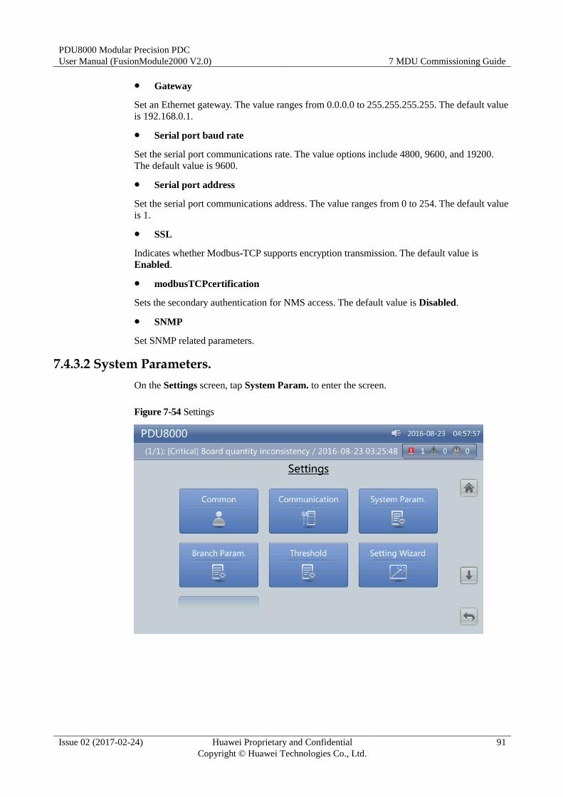
PDU8000 Modular Precision PDC
User Manual (FusionModule2000 V2.0) 7 MDU Commissioning Guide
Issue 02 (2017-02-24) Huawei Proprietary and Confidential
Copyright © Huawei Technologies Co., Ltd.
91
Gateway
Set an Ethernet gateway. The value ranges from 0.0.0.0 to 255.255.255.255. The default value
is 192.168.0.1.
Serial port baud rate
Set the serial port communications rate. The value options include 4800, 9600, and 19200.
The default value is 9600.
Serial port address
Set the serial port communications address. The value ranges from 0 to 254. The default value
is 1.
SSL
Indicates whether Modbus-TCP supports encryption transmission. The default value is
Enabled.
modbusTCPcertification
Sets the secondary authentication for NMS access. The default value is Disabled.
SNMP
Set SNMP related parameters.
7.4.3.2 System Parameters.
On the Settings screen, tap System Param. to enter the screen.
Figure 7-54 Settings
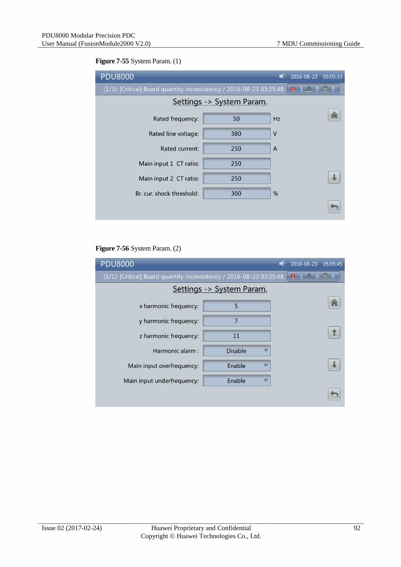
PDU8000 Modular Precision PDC
User Manual (FusionModule2000 V2.0) 7 MDU Commissioning Guide
Issue 02 (2017-02-24) Huawei Proprietary and Confidential
Copyright © Huawei Technologies Co., Ltd.
92
Figure 7-55 System Param. (1)
Figure 7-56 System Param. (2)
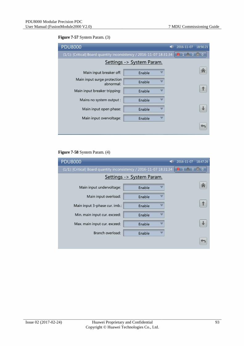
PDU8000 Modular Precision PDC
User Manual (FusionModule2000 V2.0) 7 MDU Commissioning Guide
Issue 02 (2017-02-24) Huawei Proprietary and Confidential
Copyright © Huawei Technologies Co., Ltd.
93
Figure 7-57 System Param. (3)
Figure 7-58 System Param. (4)
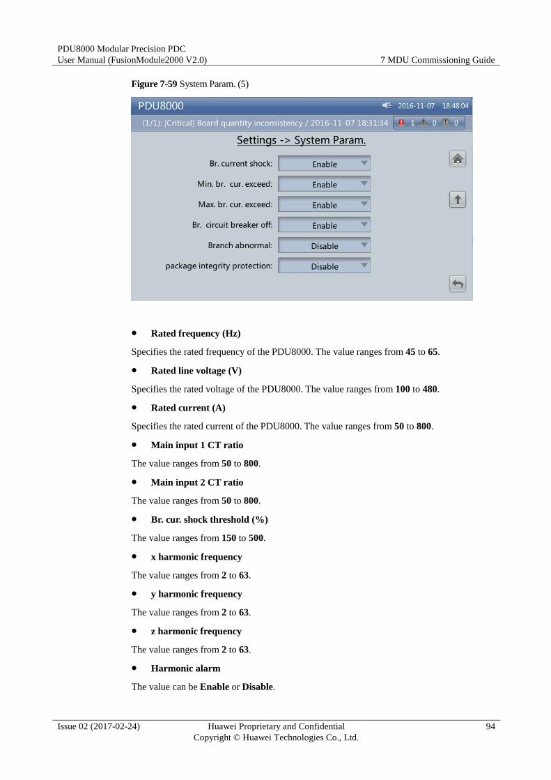
PDU8000 Modular Precision PDC
User Manual (FusionModule2000 V2.0) 7 MDU Commissioning Guide
Issue 02 (2017-02-24) Huawei Proprietary and Confidential
Copyright © Huawei Technologies Co., Ltd.
94
Figure 7-59 System Param. (5)
Rated frequency (Hz)
Specifies the rated frequency of the PDU8000. The value ranges from 45 to 65.
Rated line voltage (V)
Specifies the rated voltage of the PDU8000. The value ranges from 100 to 480.
Rated current (A)
Specifies the rated current of the PDU8000. The value ranges from 50 to 800.
Main input 1 CT ratio
The value ranges from 50 to 800.
Main input 2 CT ratio
The value ranges from 50 to 800.
Br. cur. shock threshold (%)
The value ranges from 150 to 500.
x harmonic frequency
The value ranges from 2 to 63.
y harmonic frequency
The value ranges from 2 to 63.
z harmonic frequency
The value ranges from 2 to 63.
Harmonic alarm
The value can be Enable or Disable.
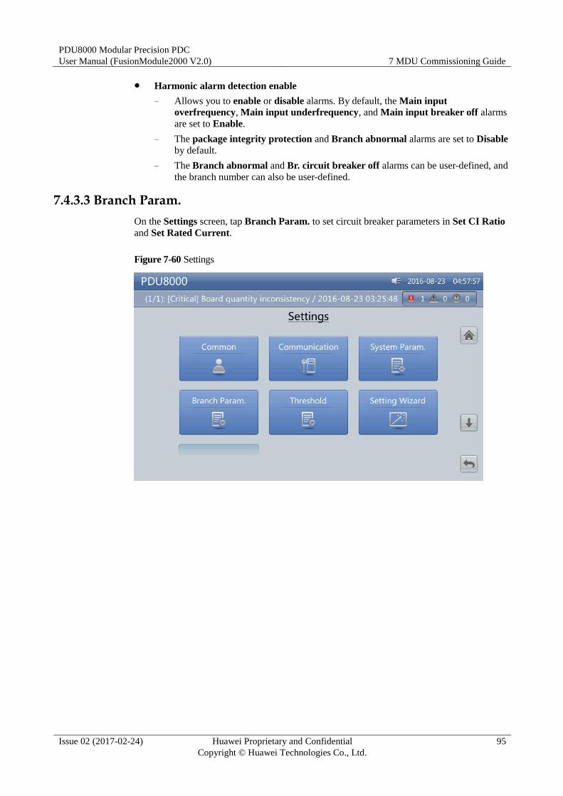
PDU8000 Modular Precision PDC
User Manual (FusionModule2000 V2.0) 7 MDU Commissioning Guide
Issue 02 (2017-02-24) Huawei Proprietary and Confidential
Copyright © Huawei Technologies Co., Ltd.
95
Harmonic alarm detection enable
− Allows you to enable or disable alarms. By default, the Main input
overfrequency, Main input underfrequency, and Main input breaker off alarms
are set to Enable.
− The package integrity protection and Branch abnormal alarms are set to Disable
by default.
− The Branch abnormal and Br. circuit breaker off alarms can be user-defined, and
the branch number can also be user-defined.
7.4.3.3 Branch Param.
On the Settings screen, tap Branch Param. to set circuit breaker parameters in Set CI Ratio
and Set Rated Current.
Figure 7-60 Settings
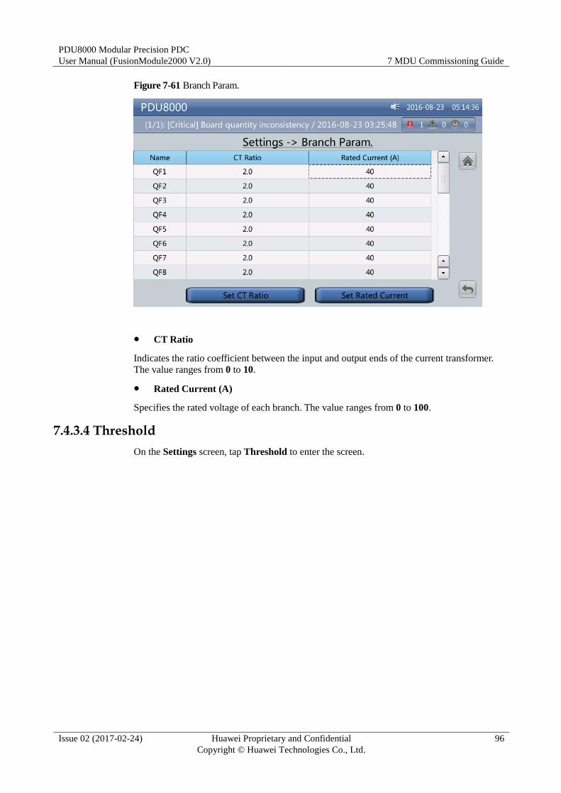
PDU8000 Modular Precision PDC
User Manual (FusionModule2000 V2.0) 7 MDU Commissioning Guide
Issue 02 (2017-02-24) Huawei Proprietary and Confidential
Copyright © Huawei Technologies Co., Ltd.
96
Figure 7-61 Branch Param.
CT Ratio
Indicates the ratio coefficient between the input and output ends of the current transformer.
The value ranges from 0 to 10.
Rated Current (A)
Specifies the rated voltage of each branch. The value ranges from 0 to 100.
7.4.3.4 Threshold
On the Settings screen, tap Threshold to enter the screen.
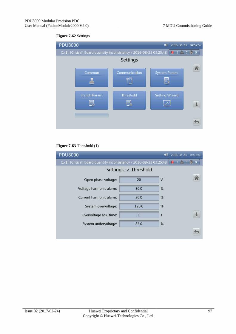
PDU8000 Modular Precision PDC
User Manual (FusionModule2000 V2.0) 7 MDU Commissioning Guide
Issue 02 (2017-02-24) Huawei Proprietary and Confidential
Copyright © Huawei Technologies Co., Ltd.
97
Figure 7-62 Settings
Figure 7-63 Threshold (1)
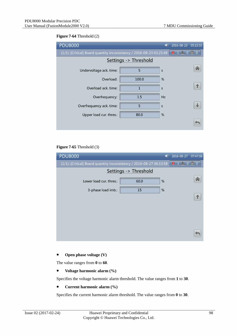
PDU8000 Modular Precision PDC
User Manual (FusionModule2000 V2.0) 7 MDU Commissioning Guide
Issue 02 (2017-02-24) Huawei Proprietary and Confidential
Copyright © Huawei Technologies Co., Ltd.
98
Figure 7-64 Threshold (2)
Figure 7-65 Threshold (3)
Open phase voltage (V)
The value ranges from 0 to 60.
Voltage harmonic alarm (%)
Specifies the voltage harmonic alarm threshold. The value ranges from 1 to 30.
Current harmonic alarm (%)
Specifies the current harmonic alarm threshold. The value ranges from 0 to 30.
PDU8000 Modular Precision PDC
User Manual (FusionModule2000 V2.0) 7 MDU Commissioning Guide
Issue 02 (2017-02-24) Huawei Proprietary and Confidential
Copyright © Huawei Technologies Co., Ltd.
99
System overvoltage (%)
Specifies the upper alarm threshold in relative to the rated voltage. The value ranges from 105
to 125.
Overvoltage ack.time (s)
Specifies the duration for confirming an overvoltage alarm. The value ranges from 1 to 10.
System undervoltage (%)
Specifies the lower alarm threshold in relative to the rated voltage. The value ranges from 75
to 95.
Undervoltage ack.time (s)
Specifies the duration for confirming an undervoltage alarm. The value ranges from 1 to 10.
Overload (%)
Specifies the overload alarm threshold in relative to the rated load. The value ranges from 100
to 120.
Overload ack.time (s)
Specifies the duration for confirming an overload alarm. The value ranges from 1 to 10.
Overfrequency (Hz)
Specifies the overfrequency alarm threshold in relative to the rated frequency. The value
ranges from 1 to 10.
Overfrequency ack.time (s)
Specifies the duration for confirming an overfrequency alarm. The value ranges from 1 to 10.
Upper load current threshold (%)
Specifies the upper alarm threshold in relative to the rated current. The value ranges from 80
to 100.
Lower Load current threshold (%)
Specifies the lower alarm threshold in relative to the rated current. The value ranges from 30
to 80.
Three-phase load imbalance (%)
Specifies the alarm threshold in relative to the balanced three-phase current. The value ranges
from 5 to 50.
7.4.4 Maintenance
The Maint screen provides the Load Config., Download Config., Download Logs, Export
Alarms, Export E-labels, Upload Modbus Config, Download Modbus Config, and
Upgrade Software menus.
On the System Info. screen, tap Maint. to enter the Maint. screen.
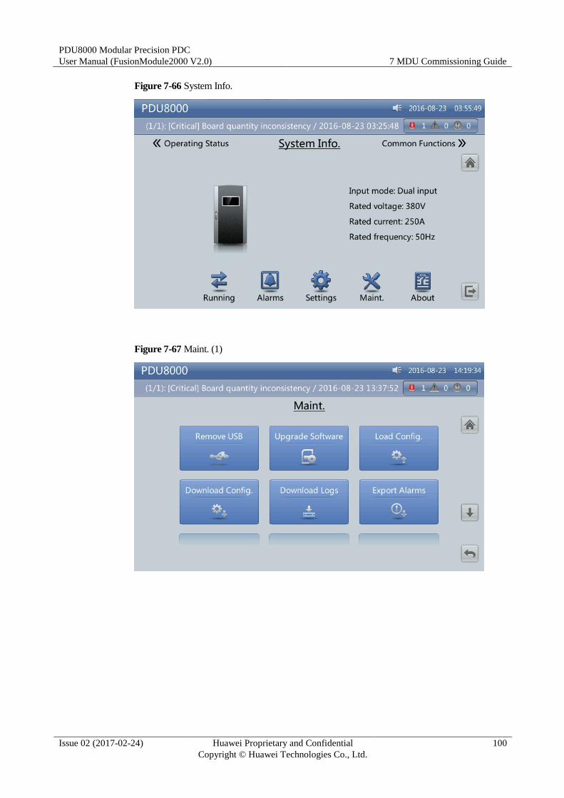
PDU8000 Modular Precision PDC
User Manual (FusionModule2000 V2.0) 7 MDU Commissioning Guide
Issue 02 (2017-02-24) Huawei Proprietary and Confidential
Copyright © Huawei Technologies Co., Ltd.
100
Figure 7-66 System Info.
Figure 7-67 Maint. (1)
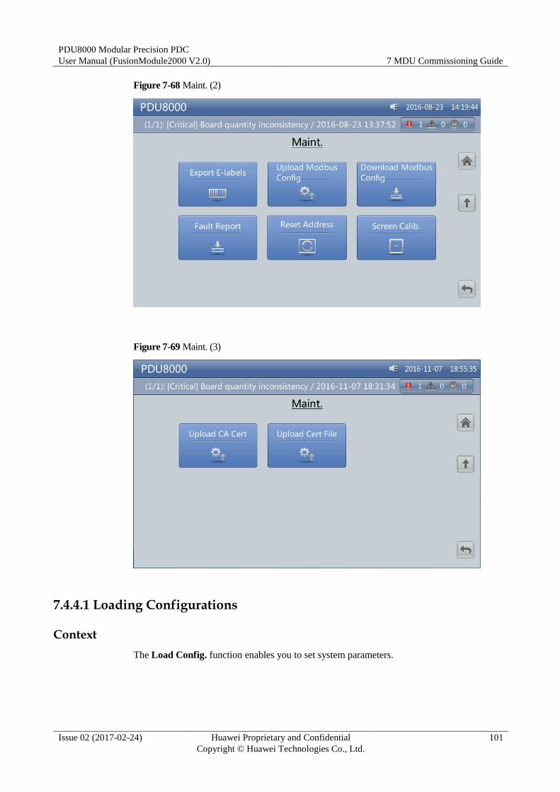
PDU8000 Modular Precision PDC
User Manual (FusionModule2000 V2.0) 7 MDU Commissioning Guide
Issue 02 (2017-02-24) Huawei Proprietary and Confidential
Copyright © Huawei Technologies Co., Ltd.
101
Figure 7-68 Maint. (2)
Figure 7-69 Maint. (3)
7.4.4.1 Loading Configurations
Context
The Load Config. function enables you to set system parameters.
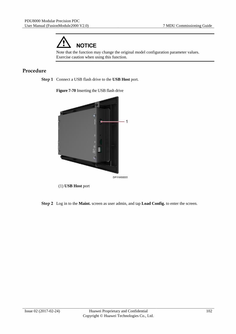
PDU8000 Modular Precision PDC
User Manual (FusionModule2000 V2.0) 7 MDU Commissioning Guide
Issue 02 (2017-02-24) Huawei Proprietary and Confidential
Copyright © Huawei Technologies Co., Ltd.
102
Note that the function may change the original model configuration parameter values.
Exercise caution when using this function.
Procedure
Step 1 Connect a USB flash drive to the USB Host port.
Figure 7-70 Inserting the USB flash drive
(1) USB Host port
Step 2 Log in to the Maint. screen as user admin, and tap Load Config. to enter the screen.
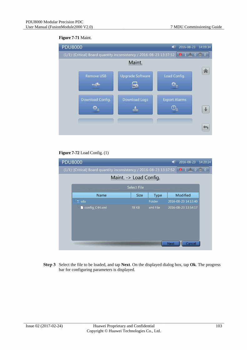
PDU8000 Modular Precision PDC
User Manual (FusionModule2000 V2.0) 7 MDU Commissioning Guide
Issue 02 (2017-02-24) Huawei Proprietary and Confidential
Copyright © Huawei Technologies Co., Ltd.
103
Figure 7-71 Maint.
Figure 7-72 Load Config. (1)
Step 3 Select the file to be loaded, and tap Next. On the displayed dialog box, tap Ok. The progress
bar for configuring parameters is displayed.
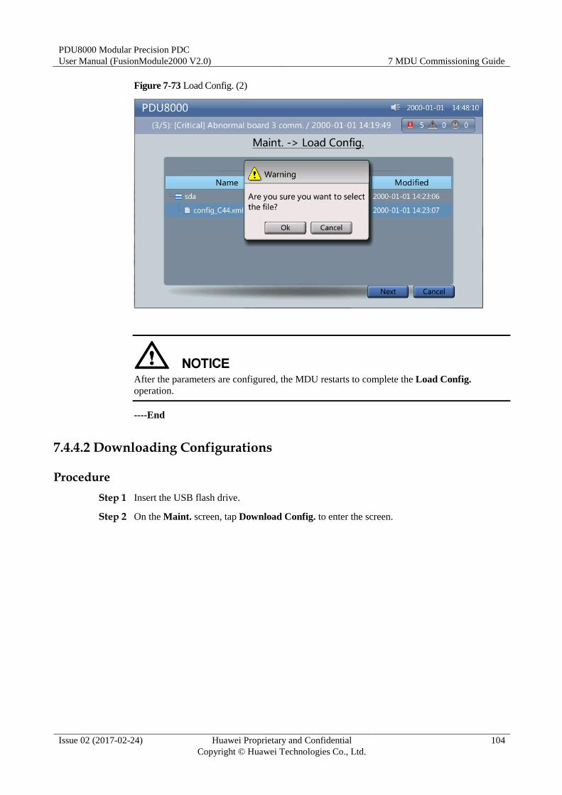
PDU8000 Modular Precision PDC
User Manual (FusionModule2000 V2.0) 7 MDU Commissioning Guide
Issue 02 (2017-02-24) Huawei Proprietary and Confidential
Copyright © Huawei Technologies Co., Ltd.
104
Figure 7-73 Load Config. (2)
After the parameters are configured, the MDU restarts to complete the Load Config.
operation.
----End
7.4.4.2 Downloading Configurations
Procedure
Step 1 Insert the USB flash drive.
Step 2 On the Maint. screen, tap Download Config. to enter the screen.

PDU8000 Modular Precision PDC
User Manual (FusionModule2000 V2.0) 7 MDU Commissioning Guide
Issue 02 (2017-02-24) Huawei Proprietary and Confidential
Copyright © Huawei Technologies Co., Ltd.
105
Figure 7-74 Maint.
Figure 7-75 Download Config. (1)
Step 3 Select the storage path and click Next to download the configurations.
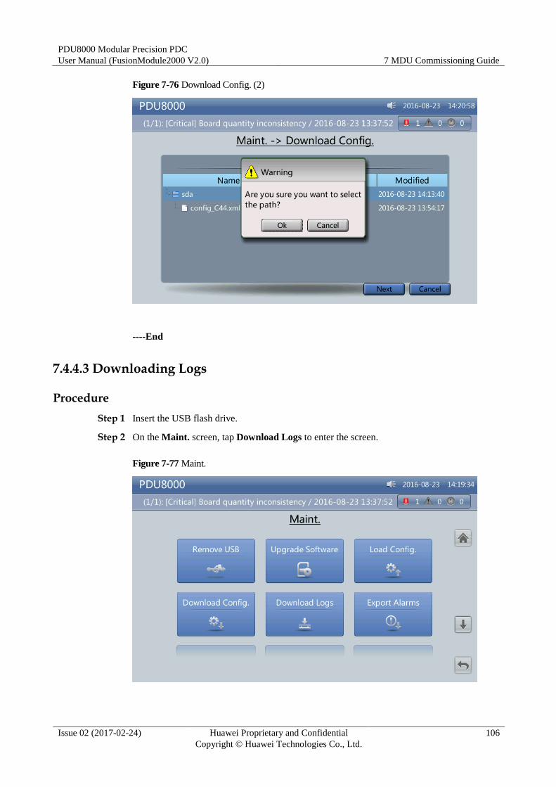
PDU8000 Modular Precision PDC
User Manual (FusionModule2000 V2.0) 7 MDU Commissioning Guide
Issue 02 (2017-02-24) Huawei Proprietary and Confidential
Copyright © Huawei Technologies Co., Ltd.
106
Figure 7-76 Download Config. (2)
----End
7.4.4.3 Downloading Logs
Procedure
Step 1 Insert the USB flash drive.
Step 2 On the Maint. screen, tap Download Logs to enter the screen.
Figure 7-77 Maint.
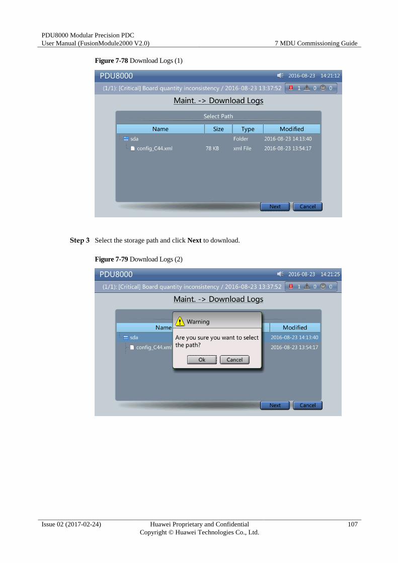
PDU8000 Modular Precision PDC
User Manual (FusionModule2000 V2.0) 7 MDU Commissioning Guide
Issue 02 (2017-02-24) Huawei Proprietary and Confidential
Copyright © Huawei Technologies Co., Ltd.
107
Figure 7-78 Download Logs (1)
Step 3 Select the storage path and click Next to download.
Figure 7-79 Download Logs (2)
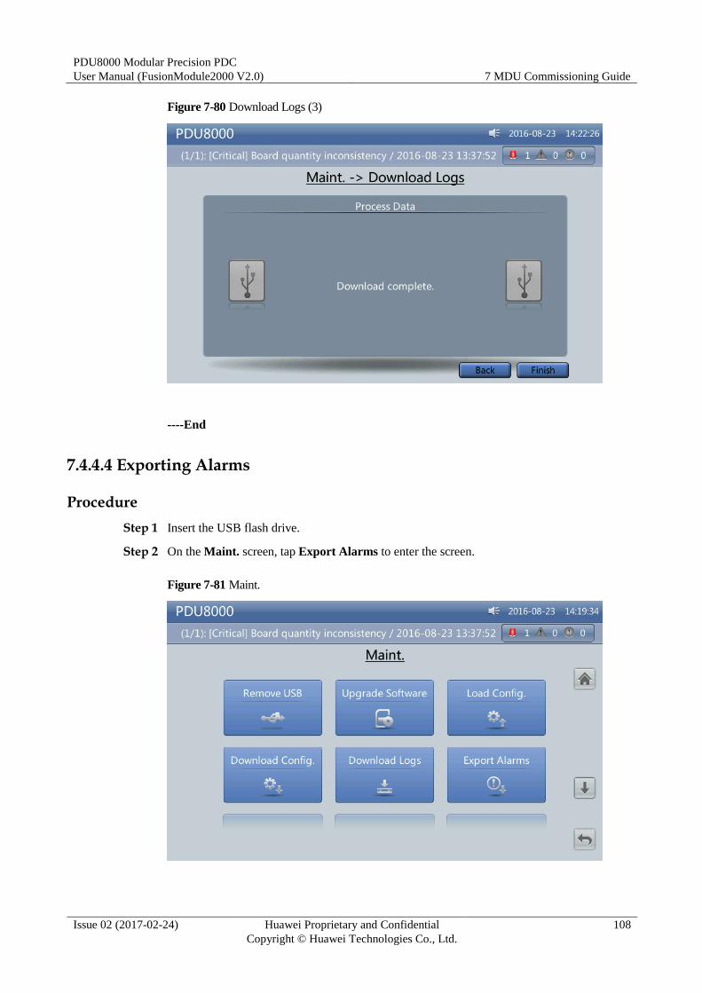
PDU8000 Modular Precision PDC
User Manual (FusionModule2000 V2.0) 7 MDU Commissioning Guide
Issue 02 (2017-02-24) Huawei Proprietary and Confidential
Copyright © Huawei Technologies Co., Ltd.
108
Figure 7-80 Download Logs (3)
----End
7.4.4.4 Exporting Alarms
Procedure
Step 1 Insert the USB flash drive.
Step 2 On the Maint. screen, tap Export Alarms to enter the screen.
Figure 7-81 Maint.
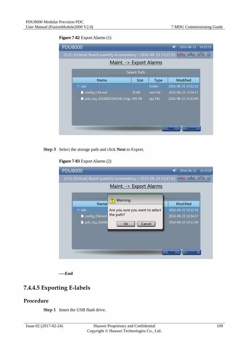
PDU8000 Modular Precision PDC
User Manual (FusionModule2000 V2.0) 7 MDU Commissioning Guide
Issue 02 (2017-02-24) Huawei Proprietary and Confidential
Copyright © Huawei Technologies Co., Ltd.
109
Figure 7-82 Export Alarms (1)
Step 3 Select the storage path and click Next to Export.
Figure 7-83 Export Alarms (2)
----End
7.4.4.5 Exporting E-labels
Procedure
Step 1 Insert the USB flash drive.
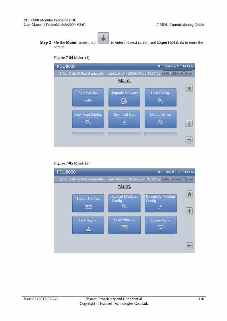
PDU8000 Modular Precision PDC
User Manual (FusionModule2000 V2.0) 7 MDU Commissioning Guide
Issue 02 (2017-02-24) Huawei Proprietary and Confidential
Copyright © Huawei Technologies Co., Ltd.
110
Step 2 On the Maint. screen, tap to enter the next screen, and Export E-labels to enter the
screen.
Figure 7-84 Maint. (1)
Figure 7-85 Maint. (2)

PDU8000 Modular Precision PDC
User Manual (FusionModule2000 V2.0) 7 MDU Commissioning Guide
Issue 02 (2017-02-24) Huawei Proprietary and Confidential
Copyright © Huawei Technologies Co., Ltd.
111
Figure 7-86 Export E-labels (1)
Step 3 Select the storage path and click Next to download the e-labels.
Figure 7-87 Export E-labels (2)
----End
7.4.4.6 Uploading Modbus Configurations
Procedure
Step 1 Insert the USB flash drive.
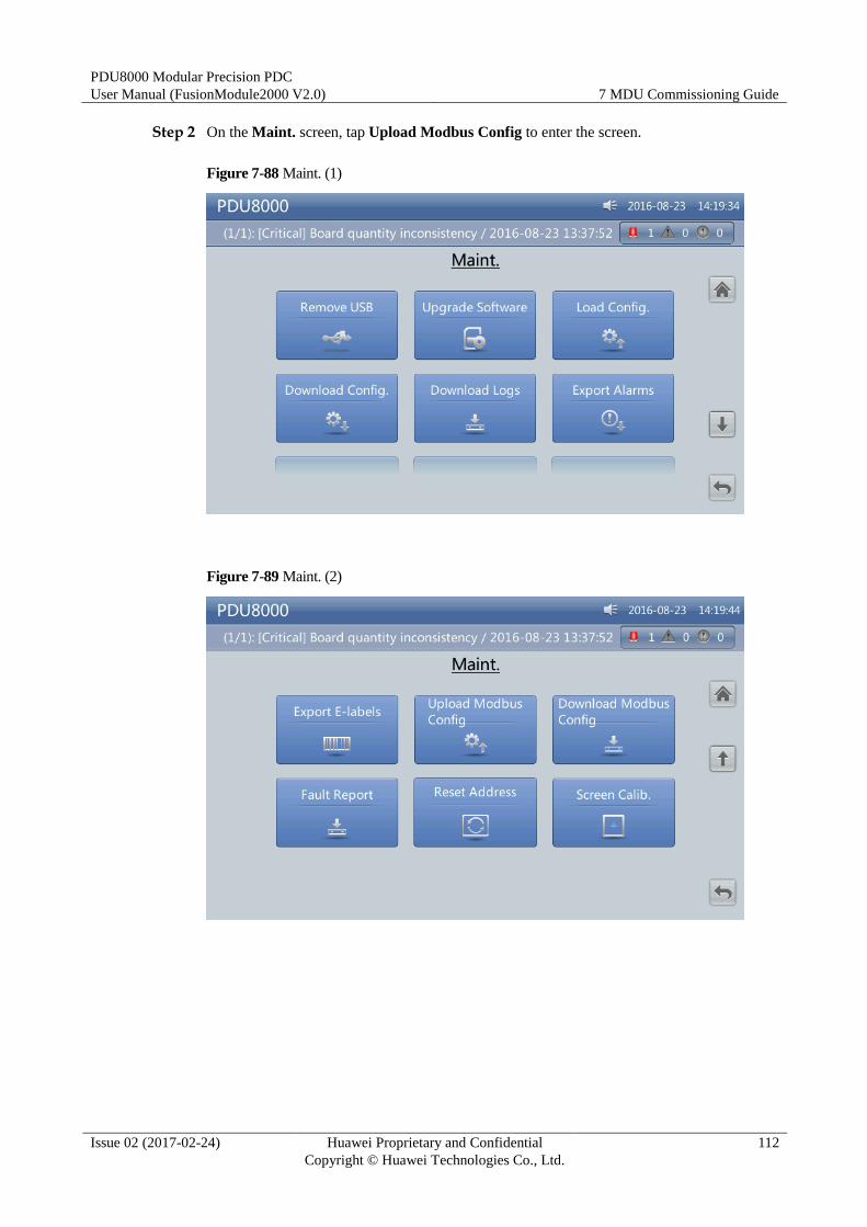
PDU8000 Modular Precision PDC
User Manual (FusionModule2000 V2.0) 7 MDU Commissioning Guide
Issue 02 (2017-02-24) Huawei Proprietary and Confidential
Copyright © Huawei Technologies Co., Ltd.
112
Step 2 On the Maint. screen, tap Upload Modbus Config to enter the screen.
Figure 7-88 Maint. (1)
Figure 7-89 Maint. (2)
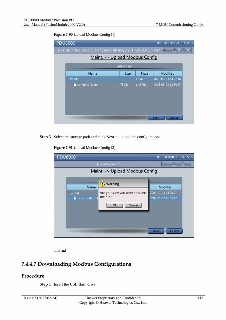
PDU8000 Modular Precision PDC
User Manual (FusionModule2000 V2.0) 7 MDU Commissioning Guide
Issue 02 (2017-02-24) Huawei Proprietary and Confidential
Copyright © Huawei Technologies Co., Ltd.
113
Figure 7-90 Upload Modbus Config (1)
Step 3 Select the storage path and click Next to upload the configurations.
Figure 7-91 Upload Modbus Config (2)
----End
7.4.4.7 Downloading Modbus Configurations
Procedure
Step 1 Insert the USB flash drive.

PDU8000 Modular Precision PDC
User Manual (FusionModule2000 V2.0) 7 MDU Commissioning Guide
Issue 02 (2017-02-24) Huawei Proprietary and Confidential
Copyright © Huawei Technologies Co., Ltd.
114
Step 2 On the Maint. screen, tap Download Modbus Config to enter the screen.
Figure 7-92 Maint. (1)
Figure 7-93 Maint. (2)

PDU8000 Modular Precision PDC
User Manual (FusionModule2000 V2.0) 7 MDU Commissioning Guide
Issue 02 (2017-02-24) Huawei Proprietary and Confidential
Copyright © Huawei Technologies Co., Ltd.
115
Figure 7-94 Download Modbus Config (1)
Step 3 Select the storage path and click Next to download the configurations.
Figure 7-95 Download Modbus Config (2)
----End
7.4.4.8 Upgrade Software
Prerequisites
To upgrade the software, perform the following steps:
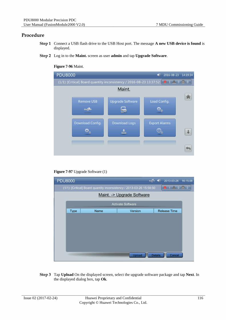
PDU8000 Modular Precision PDC
User Manual (FusionModule2000 V2.0) 7 MDU Commissioning Guide
Issue 02 (2017-02-24) Huawei Proprietary and Confidential
Copyright © Huawei Technologies Co., Ltd.
116
Procedure
Step 1 Connect a USB flash drive to the USB Host port. The message A new USB device is found is
displayed.
Step 2 Log in to the Maint. screen as user admin and tap Upgrade Software.
Figure 7-96 Maint.
Figure 7-97 Upgrade Software (1)
Step 3 Tap Upload On the displayed screen, select the upgrade software package and tap Next. In
the displayed dialog box, tap Ok.
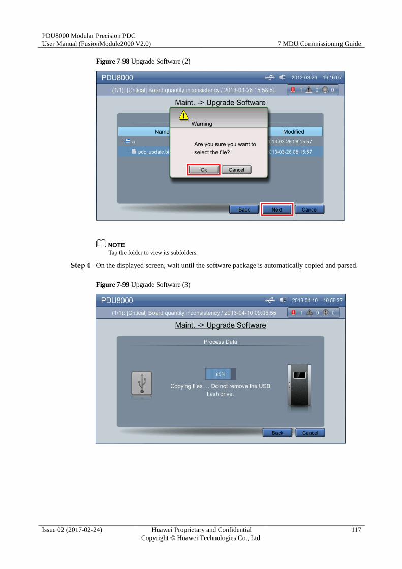
PDU8000 Modular Precision PDC
User Manual (FusionModule2000 V2.0) 7 MDU Commissioning Guide
Issue 02 (2017-02-24) Huawei Proprietary and Confidential
Copyright © Huawei Technologies Co., Ltd.
117
Figure 7-98 Upgrade Software (2)
Tap the folder to view its subfolders.
Step 4 On the displayed screen, wait until the software package is automatically copied and parsed.
Figure 7-99 Upgrade Software (3)
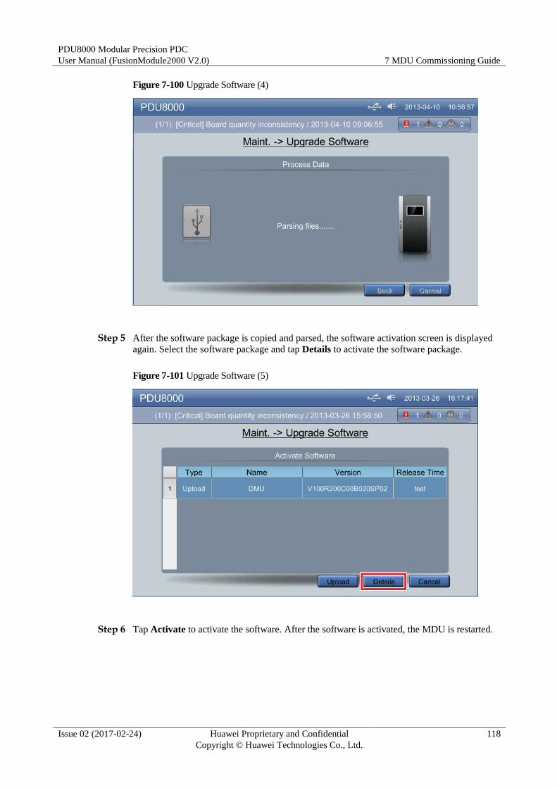
PDU8000 Modular Precision PDC
User Manual (FusionModule2000 V2.0) 7 MDU Commissioning Guide
Issue 02 (2017-02-24) Huawei Proprietary and Confidential
Copyright © Huawei Technologies Co., Ltd.
118
Figure 7-100 Upgrade Software (4)
Step 5 After the software package is copied and parsed, the software activation screen is displayed
again. Select the software package and tap Details to activate the software package.
Figure 7-101 Upgrade Software (5)
Step 6 Tap Activate to activate the software. After the software is activated, the MDU is restarted.
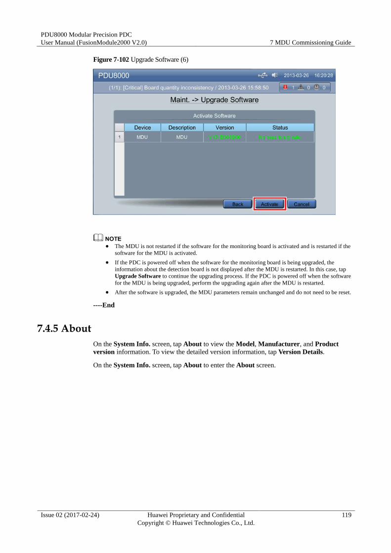
PDU8000 Modular Precision PDC
User Manual (FusionModule2000 V2.0) 7 MDU Commissioning Guide
Issue 02 (2017-02-24) Huawei Proprietary and Confidential
Copyright © Huawei Technologies Co., Ltd.
119
Figure 7-102 Upgrade Software (6)
The MDU is not restarted if the software for the monitoring board is activated and is restarted if the
software for the MDU is activated.
If the PDC is powered off when the software for the monitoring board is being upgraded, the
information about the detection board is not displayed after the MDU is restarted. In this case, tap
Upgrade Software to continue the upgrading process. If the PDC is powered off when the software
for the MDU is being upgraded, perform the upgrading again after the MDU is restarted.
After the software is upgraded, the MDU parameters remain unchanged and do not need to be reset.
----End
7.4.5 About
On the System Info. screen, tap About to view the Model, Manufacturer, and Product
version information. To view the detailed version information, tap Version Details.
On the System Info. screen, tap About to enter the About screen.
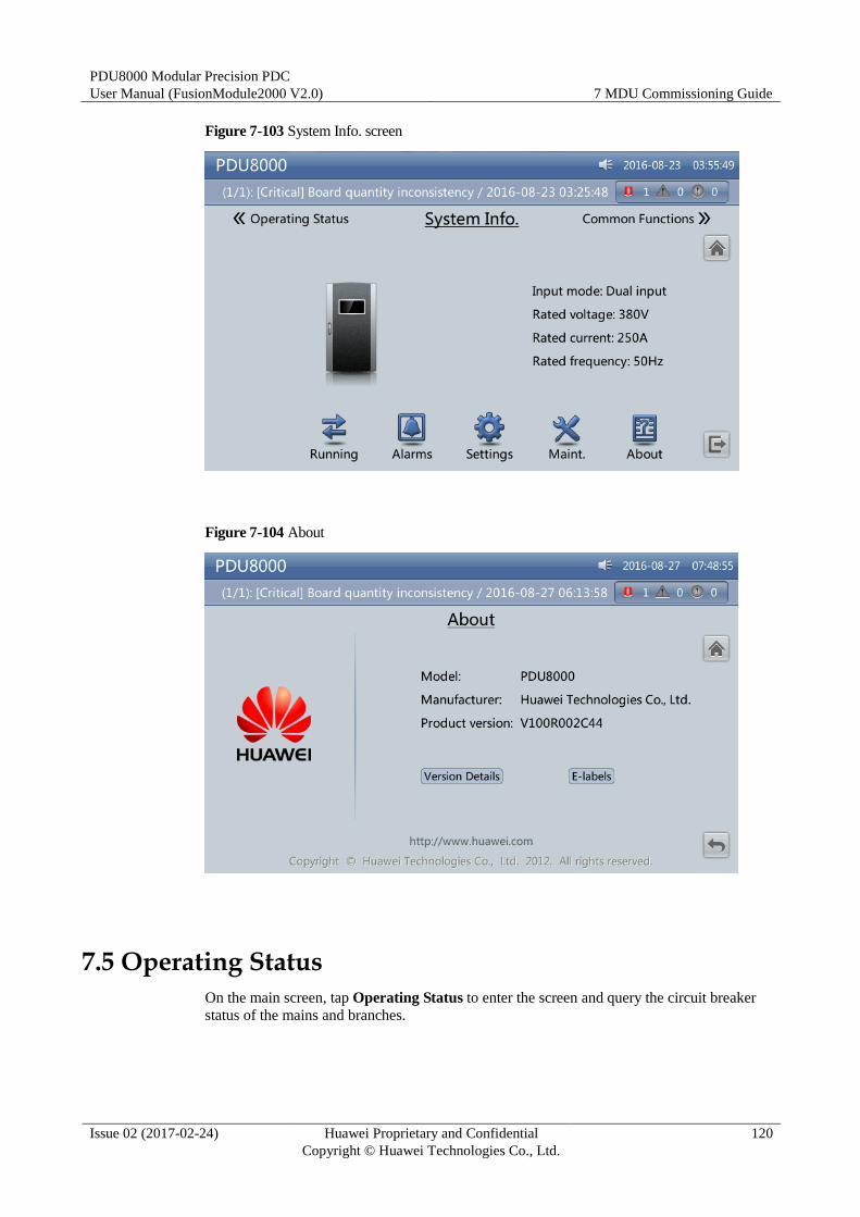
PDU8000 Modular Precision PDC
User Manual (FusionModule2000 V2.0) 7 MDU Commissioning Guide
Issue 02 (2017-02-24) Huawei Proprietary and Confidential
Copyright © Huawei Technologies Co., Ltd.
120
Figure 7-103 System Info. screen
Figure 7-104 About
7.5 Operating Status
On the main screen, tap Operating Status to enter the screen and query the circuit breaker
status of the mains and branches.
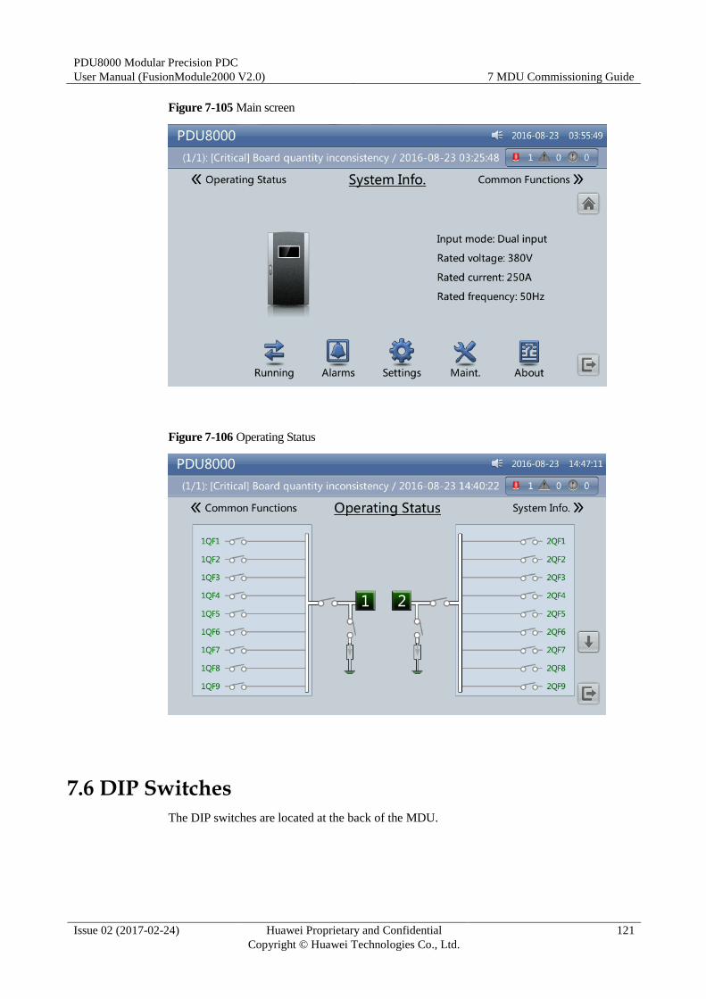
PDU8000 Modular Precision PDC
User Manual (FusionModule2000 V2.0) 7 MDU Commissioning Guide
Issue 02 (2017-02-24) Huawei Proprietary and Confidential
Copyright © Huawei Technologies Co., Ltd.
121
Figure 7-105 Main screen
Figure 7-106 Operating Status
7.6 DIP Switches
The DIP switches are located at the back of the MDU.
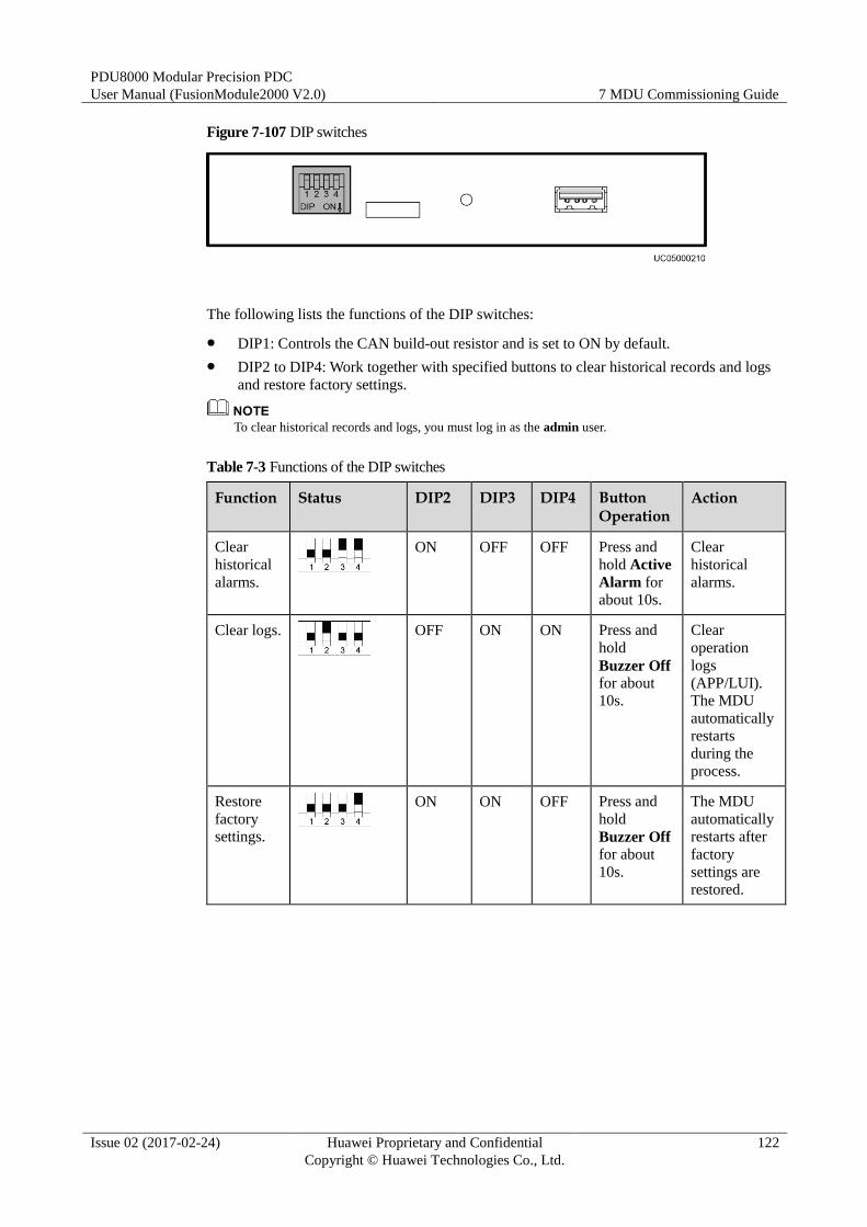
PDU8000 Modular Precision PDC
User Manual (FusionModule2000 V2.0) 7 MDU Commissioning Guide
Issue 02 (2017-02-24) Huawei Proprietary and Confidential
Copyright © Huawei Technologies Co., Ltd.
122
Figure 7-107 DIP switches
The following lists the functions of the DIP switches:
DIP1: Controls the CAN build-out resistor and is set to ON by default.
DIP2 to DIP4: Work together with specified buttons to clear historical records and logs
and restore factory settings.
To clear historical records and logs, you must log in as the admin user.
Table 7-3 Functions of the DIP switches
Function Status DIP2 DIP3 DIP4 Button Operation
Action
Clear
historical
alarms.
ON OFF OFF Press and
hold Active
Alarm for
about 10s.
Clear
historical
alarms.
Clear logs.
OFF ON ON Press and
hold
Buzzer Off for about
10s.
Clear
operation
logs
(APP/LUI).
The MDU
automatically
restarts
during the
process.
Restore
factory
settings.
ON ON OFF Press and
hold
Buzzer Off for about
10s.
The MDU
automatically
restarts after
factory
settings are
restored.
PDU8000 Modular Precision PDC
User Manual (FusionModule2000 V2.0) 8 Maintenance Guide
Issue 02 (2017-02-24) Huawei Proprietary and Confidential
Copyright © Huawei Technologies Co., Ltd.
123
8 Maintenance Guide
8.1 O&M Precautions
O&M Personnel Skill Requirements
O&M personnel must be qualified power distribution system engineers who are familiar with
the data center power supply and distribution system configurations and the operations for
each core component.
Technical Documents
Table 8-1 Technical document
Technical Document Function Obtaining Method (Remarks)
Schematic diagram Describes the control
relationship of the power
distribution system.
See the delivered
document.
8.2 Routine Maintenance
Routine maintenance is performed on a regular basis when the equipment is running properly
to find out and eliminate defects or potential risks in a timely manner.
The routine maintenance interval defines the frequency of performing maintenance tasks.
Powering off the PDC may interrupt all services. Before disconnecting power, ensure that
related emergency plans have been worked out and permissions have obtained from parties
involved. Huawei bears no responsibility for any accidents or loss.
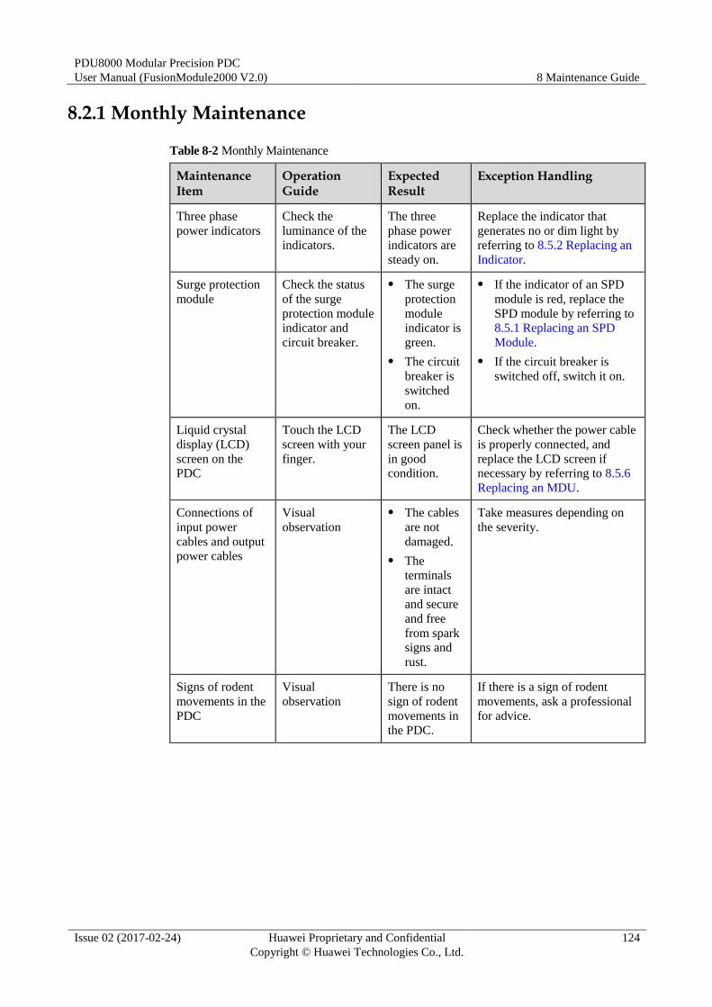
PDU8000 Modular Precision PDC
User Manual (FusionModule2000 V2.0) 8 Maintenance Guide
Issue 02 (2017-02-24) Huawei Proprietary and Confidential
Copyright © Huawei Technologies Co., Ltd.
124
8.2.1 Monthly Maintenance
Table 8-2 Monthly Maintenance
Maintenance Item
Operation Guide
Expected Result
Exception Handling
Three phase
power indicators
Check the
luminance of the
indicators.
The three
phase power
indicators are
steady on.
Replace the indicator that
generates no or dim light by
referring to 8.5.2 Replacing an
Indicator.
Surge protection
module
Check the status
of the surge
protection module
indicator and
circuit breaker.
The surge
protection
module
indicator is
green.
The circuit
breaker is
switched
on.
If the indicator of an SPD
module is red, replace the
SPD module by referring to
8.5.1 Replacing an SPD
Module.
If the circuit breaker is
switched off, switch it on.
Liquid crystal
display (LCD)
screen on the
PDC
Touch the LCD
screen with your
finger.
The LCD
screen panel is
in good
condition.
Check whether the power cable
is properly connected, and
replace the LCD screen if
necessary by referring to 8.5.6
Replacing an MDU.
Connections of
input power
cables and output
power cables
Visual
observation
The cables
are not
damaged.
The
terminals
are intact
and secure
and free
from spark
signs and
rust.
Take measures depending on
the severity.
Signs of rodent
movements in the
PDC
Visual
observation
There is no
sign of rodent
movements in
the PDC.
If there is a sign of rodent
movements, ask a professional
for advice.
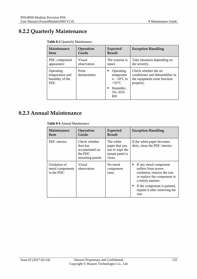
PDU8000 Modular Precision PDC
User Manual (FusionModule2000 V2.0) 8 Maintenance Guide
Issue 02 (2017-02-24) Huawei Proprietary and Confidential
Copyright © Huawei Technologies Co., Ltd.
125
8.2.2 Quarterly Maintenance
Table 8-3 Quarterly Maintenance
Maintenance Item
Operation Guide
Expected Result
Exception Handling
PDC component
appearance
Visual
observation
The exterior is
intact.
Take measures depending on
the severity.
Operating
temperature and
humidity of the
PDC
Point
thermometer
Operating
temperatur
e: –10°C to
+55°C
Humidity:
5%–95%
RH
Check whether the air
conditioner and dehumidifier in
the equipment room function
properly.
8.2.3 Annual Maintenance
Table 8-4 Annual Maintenance
Maintenance Item
Operation Guide
Expected Result
Exception Handling
PDC interior Check whether
dust has
accumulated on
the PDC
mounting panels.
The white
paper that you
use to wipe the
mount panel is
clean.
If the white paper becomes
dirty, clean the PDC interior.
Oxidation of
metal components
in the PDC
Visual
observation
No metal
component
rusts.
If any metal component
suffers from severe
oxidation, remove the rust
or replace the component in
a timely manner.
If the component is painted,
repaint it after removing the
rust.
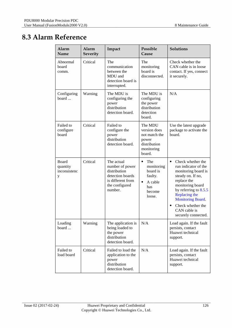
PDU8000 Modular Precision PDC
User Manual (FusionModule2000 V2.0) 8 Maintenance Guide
Issue 02 (2017-02-24) Huawei Proprietary and Confidential
Copyright © Huawei Technologies Co., Ltd.
126
8.3 Alarm Reference
Alarm Name
Alarm Severity
Impact Possible Cause
Solutions
Abnormal
board
comm.
Critical The
communication
between the
MDU and
detection board is
interrupted.
The
monitoring
board is
disconnected.
Check whether the
CAN cable is in loose
contact. If yes, connect
it securely.
Configuring
board ...
Warning The MDU is
configuring the
power
distribution
detection board.
The MDU is
configuring
the power
distribution
detection
board.
N/A
Failed to
configure
board
Critical Failed to
configure the
power
distribution
detection board.
The MDU
version does
not match the
power
distribution
monitoring
board.
Use the latest upgrade
package to activate the
board.
Board
quantity
inconsistenc
y
Critical The actual
number of power
distribution
detection boards
is different from
the configured
number.
The
monitoring
board is
faulty.
A cable
has
become
loose.
Check whether the
run indicator of the
monitoring board is
steady on. If no,
replace the
monitoring board
by referring to 8.5.5
Replacing the
Monitoring Board.
Check whether the
CAN cable is
securely connected.
Loading
board ... Warning The application is
being loaded to
the power
distribution
detection board.
N/A Load again. If the fault
persists, contact
Huawei technical
support.
Failed to
load board Critical Failed to load the
application to the
power
distribution
detection board.
N/A Load again. If the fault
persists, contact
Huawei technical
support.
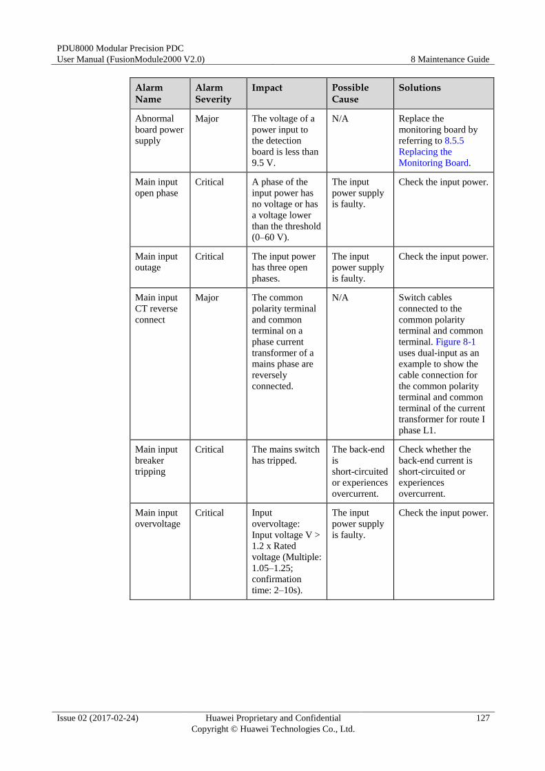
PDU8000 Modular Precision PDC
User Manual (FusionModule2000 V2.0) 8 Maintenance Guide
Issue 02 (2017-02-24) Huawei Proprietary and Confidential
Copyright © Huawei Technologies Co., Ltd.
127
Alarm Name
Alarm Severity
Impact Possible Cause
Solutions
Abnormal
board power
supply
Major The voltage of a
power input to
the detection
board is less than
9.5 V.
N/A Replace the
monitoring board by
referring to 8.5.5
Replacing the
Monitoring Board.
Main input
open phase
Critical A phase of the
input power has
no voltage or has
a voltage lower
than the threshold
(0–60 V).
The input
power supply
is faulty.
Check the input power.
Main input
outage Critical The input power
has three open
phases.
The input
power supply
is faulty.
Check the input power.
Main input
CT reverse
connect
Major The common
polarity terminal
and common
terminal on a
phase current
transformer of a
mains phase are
reversely
connected.
N/A Switch cables
connected to the
common polarity
terminal and common
terminal. Figure 8-1
uses dual-input as an
example to show the
cable connection for
the common polarity
terminal and common
terminal of the current
transformer for route I
phase L1.
Main input
breaker
tripping
Critical The mains switch
has tripped.
The back-end
is
short-circuited
or experiences
overcurrent.
Check whether the
back-end current is
short-circuited or
experiences
overcurrent.
Main input
overvoltage
Critical Input
overvoltage:
Input voltage V >
1.2 x Rated
voltage (Multiple:
1.05–1.25;
confirmation
time: 2–10s).
The input
power supply
is faulty.
Check the input power.
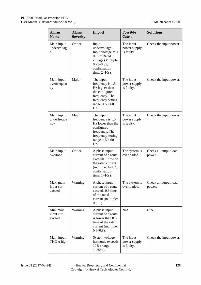
PDU8000 Modular Precision PDC
User Manual (FusionModule2000 V2.0) 8 Maintenance Guide
Issue 02 (2017-02-24) Huawei Proprietary and Confidential
Copyright © Huawei Technologies Co., Ltd.
128
Alarm Name
Alarm Severity
Impact Possible Cause
Solutions
Main input
undervoltag
e
Critical Input
undervoltage:
Input voltage V <
0.85 x Rated
voltage (Multiple:
0.75–0.95;
confirmation
time: 2–10s).
The input
power supply
is faulty.
Check the input power.
Main input
overfrequen
cy
Major The input
frequency is 1.5
Hz higher than
the configured
frequency. The
frequency setting
range is 50–60
Hz.
The input
power supply
is faulty.
Check the input power.
Main input
underfreque
ncy
Major The input
frequency is 1.5
Hz lower than the
configured
frequency. The
frequency setting
range is 50–60
Hz.
The input
power supply
is faulty.
Check the input power.
Main input
overload
Critical A phase input
current of a route
exceeds 1 time of
the rated current
(multiple: 1–1.2;
confirmation
time: 1–10s).
The system is
overloaded.
Check all output load
power.
Max. main
input cur.
exceed
Warning A phase input
current of a route
exceeds 0.8 time
of the rated
current (multiple:
0.8–1).
The system is
overloaded.
Check all output load
power.
Min. main
input cur.
exceed
Warning A phase input
current of a route
is lower than 0.6
time of the rated
current (multiple:
0.6–0.8).
N/A N/A
Main input
THD-u high
Warning System voltage
harmonic exceeds
10% (range:
1–30%).
The input
power supply
is faulty.
Check the input power.

PDU8000 Modular Precision PDC
User Manual (FusionModule2000 V2.0) 8 Maintenance Guide
Issue 02 (2017-02-24) Huawei Proprietary and Confidential
Copyright © Huawei Technologies Co., Ltd.
129
Alarm Name
Alarm Severity
Impact Possible Cause
Solutions
Main input
THD-i high
Warning System current
harmonic exceeds
10% (range:
0–30%).
The input
power supply
is faulty.
Check the input power.
Main input
surge
protection
abnormal
Major Any dry contact
on the SPD
connecting to the
mains input is
disconnected.
A surge
protection
module is
damaged or
the SPD
circuit breaker
has tripped.
Replace the surge
protection module by
referring to 8.5.1
Replacing an SPD
Module or switch on
the SPD circuit
breaker.
Main input
breaker off Warning A mains switch
has changed from
ON to OFF.
N/A N/A
Br. circuit
breaker off
Critical A branch switch
has changed from
ON to OFF.
N/A N/A
Branch
abnormal
Warning A branch switch
is on, but no
current is
detected.
N/A N/A
Branch
overload
Critical The current of a
branch exceeds 1
time of the rated
current (multiple:
1–1.2;
confirmation
time: 1–10s).
The branch is
overloaded.
Check the load power
of the branch.
Max. br. cur.
exceed
Major The current of a
branch exceeds
0.8 time of the
rated current
(multiple: 0.8–1).
The branch is
overloaded.
Check the load power
of the branch.
Min. br. cur.
exceed
Warning The current of a
branch exceeds
0.6 time of the
rated current
(multiple:
0.6–0.8;
confirmation
time: 1–10s).
N/A N/A
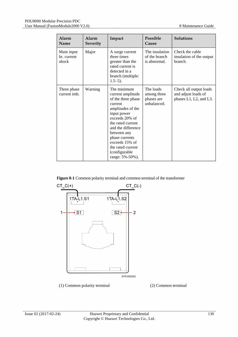
PDU8000 Modular Precision PDC
User Manual (FusionModule2000 V2.0) 8 Maintenance Guide
Issue 02 (2017-02-24) Huawei Proprietary and Confidential
Copyright © Huawei Technologies Co., Ltd.
130
Alarm Name
Alarm Severity
Impact Possible Cause
Solutions
Main input
br. current
shock
Major A surge current
three times
greater than the
rated current is
detected in a
branch (multiple:
1.5–5).
The insulation
of the branch
is abnormal.
Check the cable
insulation of the output
branch.
Three phase
current imb.
Warning The minimum
current amplitude
of the three phase
current
amplitudes of the
input power
exceeds 20% of
the rated current
and the difference
between any
phase currents
exceeds 15% of
the rated current
(configurable
range: 5%-50%).
The loads
among three
phases are
unbalanced.
Check all output loads
and adjust loads of
phases L1, L2, and L3.
Figure 8-1 Common polarity terminal and common terminal of the transformer
(1) Common polarity terminal (2) Common terminal
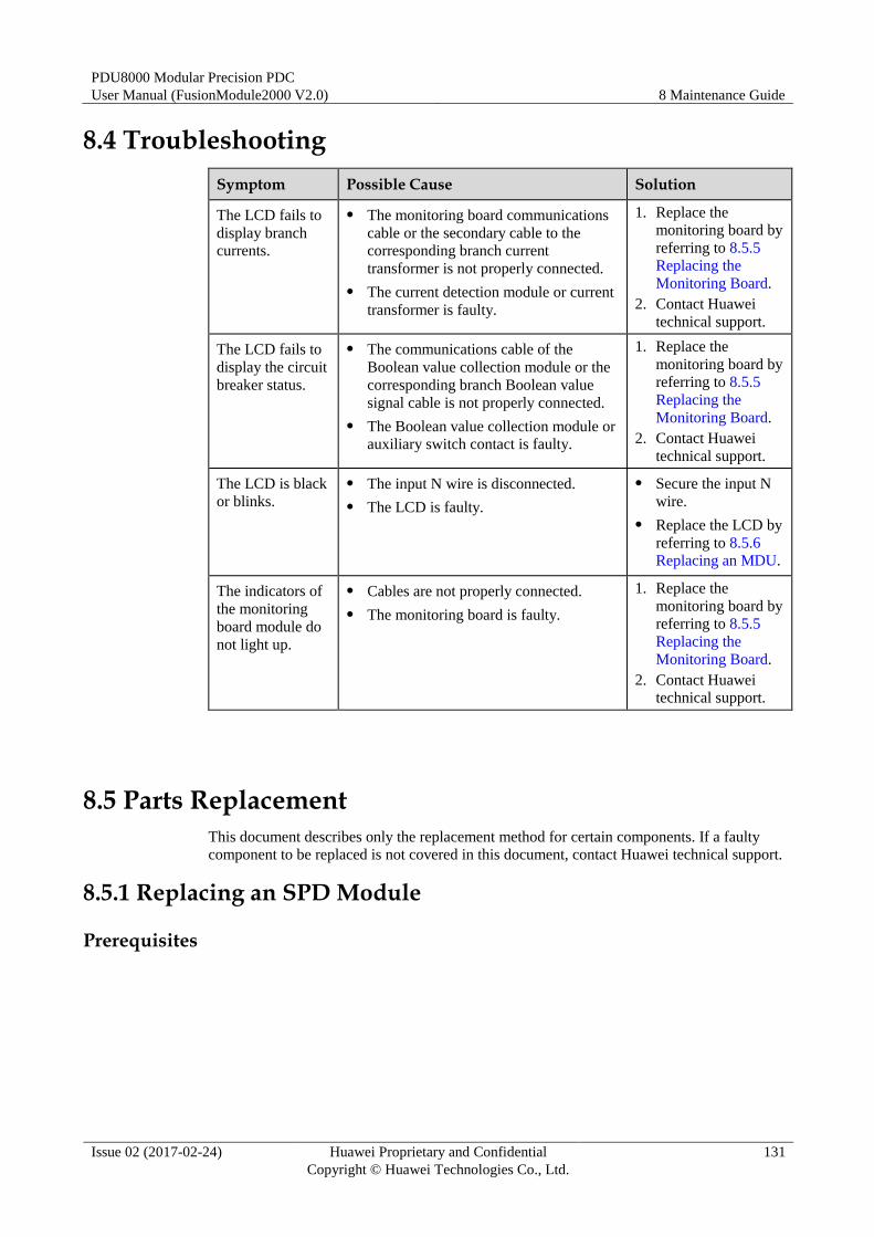
PDU8000 Modular Precision PDC
User Manual (FusionModule2000 V2.0) 8 Maintenance Guide
Issue 02 (2017-02-24) Huawei Proprietary and Confidential
Copyright © Huawei Technologies Co., Ltd.
131
8.4 Troubleshooting
Symptom Possible Cause Solution
The LCD fails to
display branch
currents.
The monitoring board communications
cable or the secondary cable to the
corresponding branch current
transformer is not properly connected.
The current detection module or current
transformer is faulty.
1. Replace the
monitoring board by
referring to 8.5.5
Replacing the
Monitoring Board.
2. Contact Huawei
technical support.
The LCD fails to
display the circuit
breaker status.
The communications cable of the
Boolean value collection module or the
corresponding branch Boolean value
signal cable is not properly connected.
The Boolean value collection module or
auxiliary switch contact is faulty.
1. Replace the
monitoring board by
referring to 8.5.5
Replacing the
Monitoring Board.
2. Contact Huawei
technical support.
The LCD is black
or blinks.
The input N wire is disconnected.
The LCD is faulty.
Secure the input N
wire.
Replace the LCD by
referring to 8.5.6
Replacing an MDU.
The indicators of
the monitoring
board module do
not light up.
Cables are not properly connected.
The monitoring board is faulty.
1. Replace the
monitoring board by
referring to 8.5.5
Replacing the
Monitoring Board.
2. Contact Huawei
technical support.
8.5 Parts Replacement
This document describes only the replacement method for certain components. If a faulty
component to be replaced is not covered in this document, contact Huawei technical support.
8.5.1 Replacing an SPD Module
Prerequisites
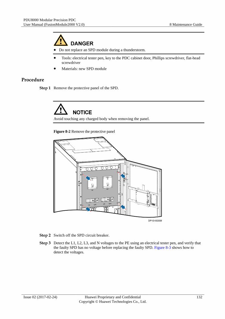
PDU8000 Modular Precision PDC
User Manual (FusionModule2000 V2.0) 8 Maintenance Guide
Issue 02 (2017-02-24) Huawei Proprietary and Confidential
Copyright © Huawei Technologies Co., Ltd.
132
Do not replace an SPD module during a thunderstorm.
Tools: electrical tester pen, key to the PDC cabinet door, Phillips screwdriver, flat-head
screwdriver
Materials: new SPD module
Procedure
Step 1 Remove the protective panel of the SPD.
Avoid touching any charged body when removing the panel.
Figure 8-2 Remove the protective panel
Step 2 Switch off the SPD circuit breaker.
Step 3 Detect the L1, L2, L3, and N voltages to the PE using an electrical tester pen, and verify that
the faulty SPD has no voltage before replacing the faulty SPD. Figure 8-3 shows how to
detect the voltages.
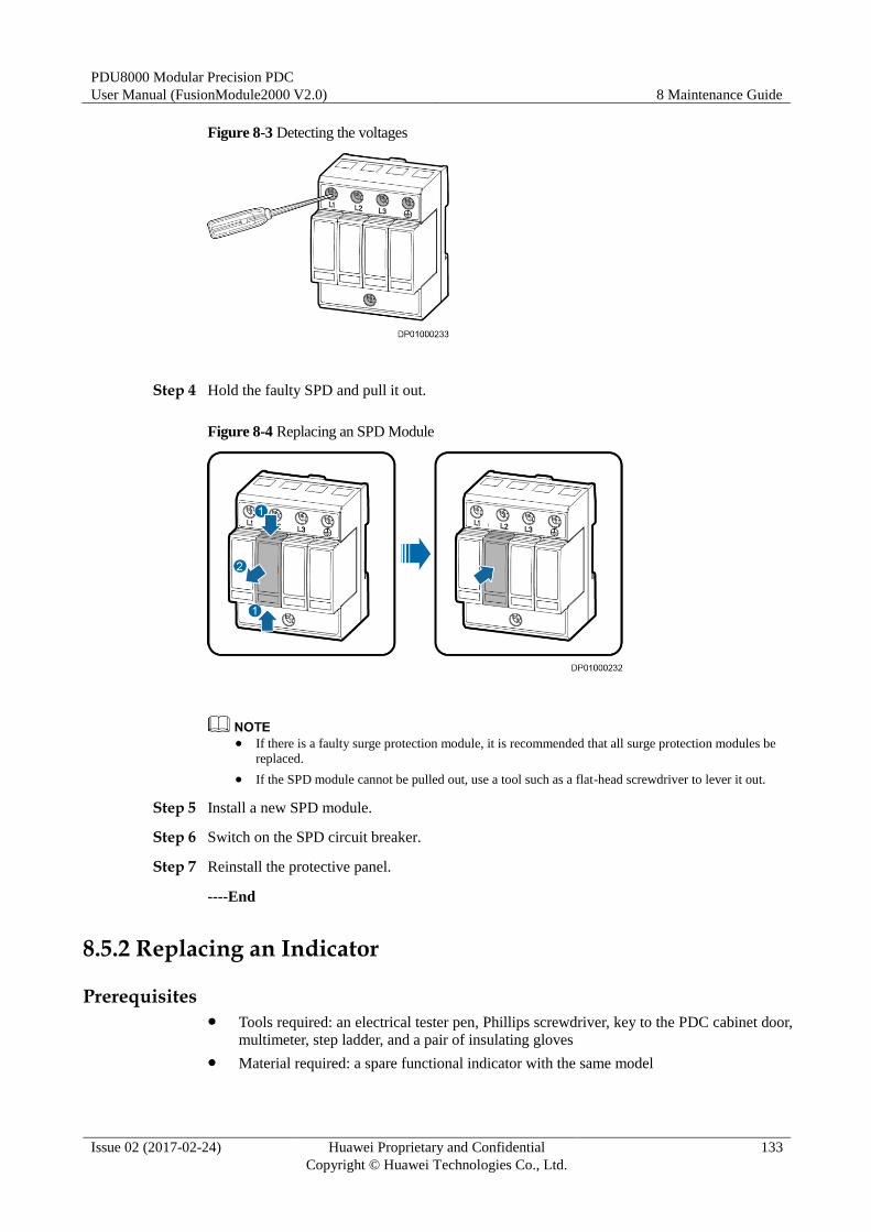
PDU8000 Modular Precision PDC
User Manual (FusionModule2000 V2.0) 8 Maintenance Guide
Issue 02 (2017-02-24) Huawei Proprietary and Confidential
Copyright © Huawei Technologies Co., Ltd.
133
Figure 8-3 Detecting the voltages
Step 4 Hold the faulty SPD and pull it out.
Figure 8-4 Replacing an SPD Module
If there is a faulty surge protection module, it is recommended that all surge protection modules be
replaced.
If the SPD module cannot be pulled out, use a tool such as a flat-head screwdriver to lever it out.
Step 5 Install a new SPD module.
Step 6 Switch on the SPD circuit breaker.
Step 7 Reinstall the protective panel.
----End
8.5.2 Replacing an Indicator
Prerequisites Tools required: an electrical tester pen, Phillips screwdriver, key to the PDC cabinet door,
multimeter, step ladder, and a pair of insulating gloves
Material required: a spare functional indicator with the same model
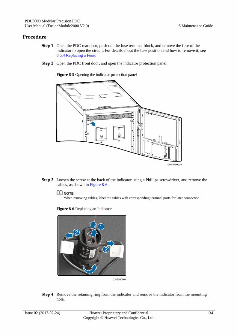
PDU8000 Modular Precision PDC
User Manual (FusionModule2000 V2.0) 8 Maintenance Guide
Issue 02 (2017-02-24) Huawei Proprietary and Confidential
Copyright © Huawei Technologies Co., Ltd.
134
Procedure
Step 1 Open the PDC rear door, push out the fuse terminal block, and remove the fuse of the
indicator to open the circuit. For details about the fuse position and how to remove it, see
8.5.4 Replacing a Fuse.
Step 2 Open the PDC front door, and open the indicator protection panel.
Figure 8-5 Opening the indicator protection panel
Step 3 Loosen the screw at the back of the indicator using a Phillips screwdriver, and remove the
cables, as shown in Figure 8-6.
When removing cables, label the cables with corresponding terminal ports for later connection.
Figure 8-6 Replacing an Indicator
Step 4 Remove the retaining ring from the indicator and remove the indicator from the mounting
hole.
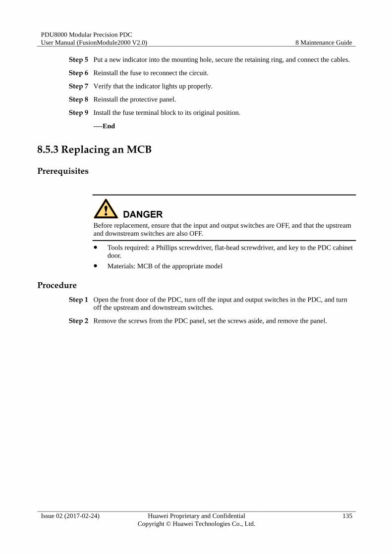
PDU8000 Modular Precision PDC
User Manual (FusionModule2000 V2.0) 8 Maintenance Guide
Issue 02 (2017-02-24) Huawei Proprietary and Confidential
Copyright © Huawei Technologies Co., Ltd.
135
Step 5 Put a new indicator into the mounting hole, secure the retaining ring, and connect the cables.
Step 6 Reinstall the fuse to reconnect the circuit.
Step 7 Verify that the indicator lights up properly.
Step 8 Reinstall the protective panel.
Step 9 Install the fuse terminal block to its original position.
----End
8.5.3 Replacing an MCB
Prerequisites
Before replacement, ensure that the input and output switches are OFF, and that the upstream
and downstream switches are also OFF.
Tools required: a Phillips screwdriver, flat-head screwdriver, and key to the PDC cabinet
door.
Materials: MCB of the appropriate model
Procedure
Step 1 Open the front door of the PDC, turn off the input and output switches in the PDC, and turn
off the upstream and downstream switches.
Step 2 Remove the screws from the PDC panel, set the screws aside, and remove the panel.
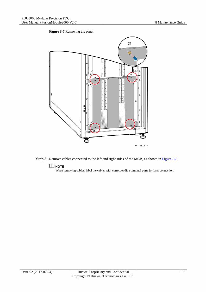
PDU8000 Modular Precision PDC
User Manual (FusionModule2000 V2.0) 8 Maintenance Guide
Issue 02 (2017-02-24) Huawei Proprietary and Confidential
Copyright © Huawei Technologies Co., Ltd.
136
Figure 8-7 Removing the panel
Step 3 Remove cables connected to the left and right sides of the MCB, as shown in Figure 8-8.
When removing cables, label the cables with corresponding terminal ports for later connection.
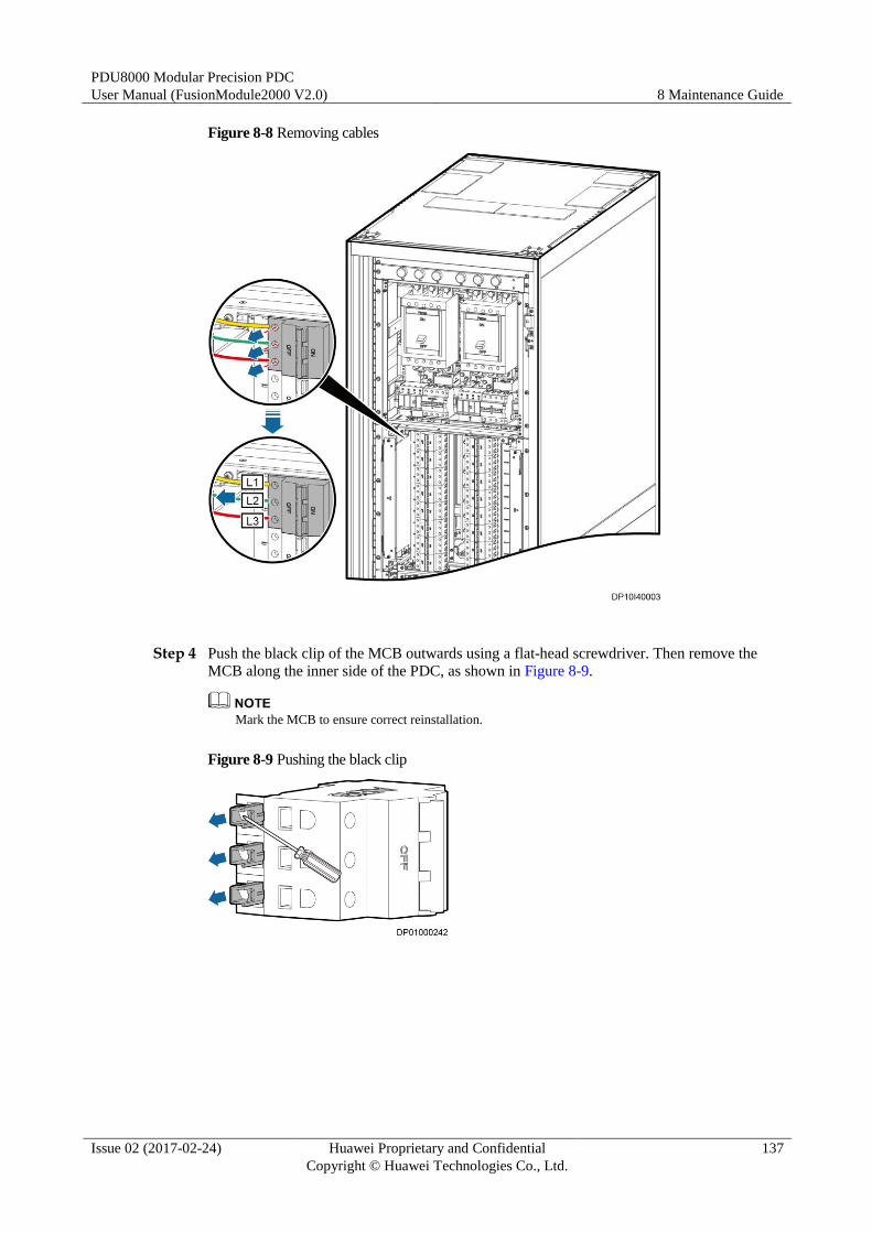
PDU8000 Modular Precision PDC
User Manual (FusionModule2000 V2.0) 8 Maintenance Guide
Issue 02 (2017-02-24) Huawei Proprietary and Confidential
Copyright © Huawei Technologies Co., Ltd.
137
Figure 8-8 Removing cables
Step 4 Push the black clip of the MCB outwards using a flat-head screwdriver. Then remove the
MCB along the inner side of the PDC, as shown in Figure 8-9.
Mark the MCB to ensure correct reinstallation.
Figure 8-9 Pushing the black clip

PDU8000 Modular Precision PDC
User Manual (FusionModule2000 V2.0) 8 Maintenance Guide
Issue 02 (2017-02-24) Huawei Proprietary and Confidential
Copyright © Huawei Technologies Co., Ltd.
138
Figure 8-10 Removing the MCB
Step 5 Install a new MCB.
Step 6 Connect cables. The recommended cable hole for the MCB is shown by (1) in Figure 8-11.
Figure 8-11 Mounting holes
(1) mounting holes
Step 7 Reinstall the panel on the PDC.
----End
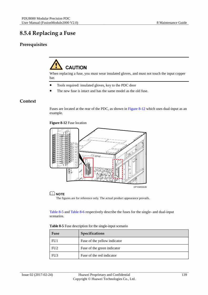
PDU8000 Modular Precision PDC
User Manual (FusionModule2000 V2.0) 8 Maintenance Guide
Issue 02 (2017-02-24) Huawei Proprietary and Confidential
Copyright © Huawei Technologies Co., Ltd.
139
8.5.4 Replacing a Fuse
Prerequisites
When replacing a fuse, you must wear insulated gloves, and must not touch the input copper
bar.
Tools required: insulated gloves, key to the PDC door
The new fuse is intact and has the same model as the old fuse.
Context
Fuses are located at the rear of the PDC, as shown in Figure 8-12 which uses dual-input as an
example.
Figure 8-12 Fuse location
The figures are for reference only. The actual product appearance prevails.
Table 8-5 and Table 8-6 respectively describe the fuses for the single- and dual-input
scenarios.
Table 8-5 Fuse description for the single-input scenario
Fuse Specifications
FU1 Fuse of the yellow indicator
FU2 Fuse of the green indicator
FU3 Fuse of the red indicator
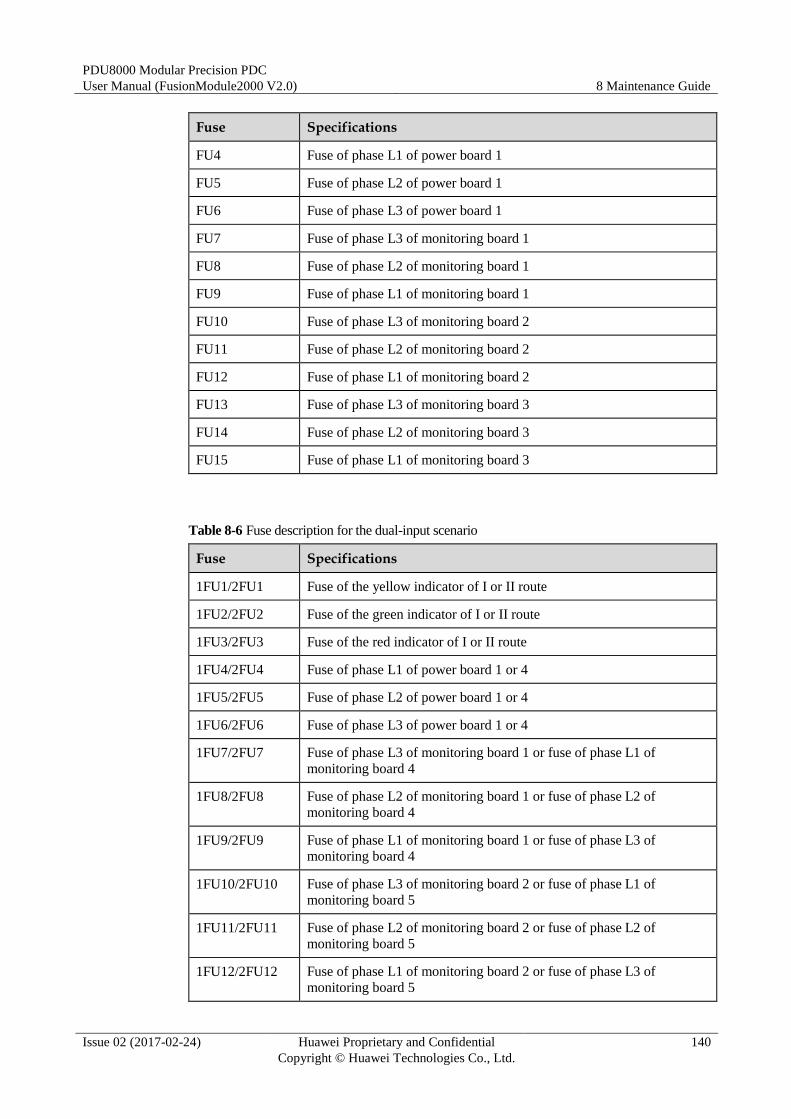
PDU8000 Modular Precision PDC
User Manual (FusionModule2000 V2.0) 8 Maintenance Guide
Issue 02 (2017-02-24) Huawei Proprietary and Confidential
Copyright © Huawei Technologies Co., Ltd.
140
Fuse Specifications
FU4 Fuse of phase L1 of power board 1
FU5 Fuse of phase L2 of power board 1
FU6 Fuse of phase L3 of power board 1
FU7 Fuse of phase L3 of monitoring board 1
FU8 Fuse of phase L2 of monitoring board 1
FU9 Fuse of phase L1 of monitoring board 1
FU10 Fuse of phase L3 of monitoring board 2
FU11 Fuse of phase L2 of monitoring board 2
FU12 Fuse of phase L1 of monitoring board 2
FU13 Fuse of phase L3 of monitoring board 3
FU14 Fuse of phase L2 of monitoring board 3
FU15 Fuse of phase L1 of monitoring board 3
Table 8-6 Fuse description for the dual-input scenario
Fuse Specifications
1FU1/2FU1 Fuse of the yellow indicator of I or II route
1FU2/2FU2 Fuse of the green indicator of I or II route
1FU3/2FU3 Fuse of the red indicator of I or II route
1FU4/2FU4 Fuse of phase L1 of power board 1 or 4
1FU5/2FU5 Fuse of phase L2 of power board 1 or 4
1FU6/2FU6 Fuse of phase L3 of power board 1 or 4
1FU7/2FU7 Fuse of phase L3 of monitoring board 1 or fuse of phase L1 of
monitoring board 4
1FU8/2FU8 Fuse of phase L2 of monitoring board 1 or fuse of phase L2 of
monitoring board 4
1FU9/2FU9 Fuse of phase L1 of monitoring board 1 or fuse of phase L3 of
monitoring board 4
1FU10/2FU10 Fuse of phase L3 of monitoring board 2 or fuse of phase L1 of
monitoring board 5
1FU11/2FU11 Fuse of phase L2 of monitoring board 2 or fuse of phase L2 of
monitoring board 5
1FU12/2FU12 Fuse of phase L1 of monitoring board 2 or fuse of phase L3 of
monitoring board 5
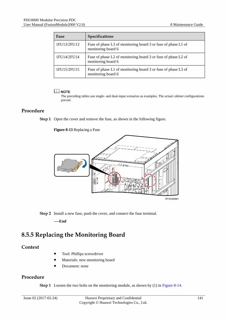
PDU8000 Modular Precision PDC
User Manual (FusionModule2000 V2.0) 8 Maintenance Guide
Issue 02 (2017-02-24) Huawei Proprietary and Confidential
Copyright © Huawei Technologies Co., Ltd.
141
Fuse Specifications
1FU13/2FU13 Fuse of phase L3 of monitoring board 3 or fuse of phase L1 of
monitoring board 6
1FU14/2FU14 Fuse of phase L2 of monitoring board 3 or fuse of phase L2 of
monitoring board 6
1FU15/2FU15 Fuse of phase L1 of monitoring board 3 or fuse of phase L3 of
monitoring board 6
The preceding tables use single- and dual-input scenarios as examples. The actual cabinet configurations
prevail.
Procedure
Step 1 Open the cover and remove the fuse, as shown in the following figure.
Figure 8-13 Replacing a Fuse
Step 2 Install a new fuse, push the cover, and connect the fuse terminal.
----End
8.5.5 Replacing the Monitoring Board
Context Tool: Phillips screwdriver
Materials: new monitoring board
Document: none
Procedure
Step 1 Loosen the two bolts on the monitoring module, as shown by (1) in Figure 8-14.
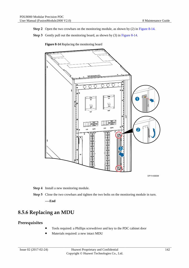
PDU8000 Modular Precision PDC
User Manual (FusionModule2000 V2.0) 8 Maintenance Guide
Issue 02 (2017-02-24) Huawei Proprietary and Confidential
Copyright © Huawei Technologies Co., Ltd.
142
Step 2 Open the two crowbars on the monitoring module, as shown by (2) in Figure 8-14.
Step 3 Gently pull out the monitoring board, as shown by (3) in Figure 8-14.
Figure 8-14 Replacing the monitoring board
Step 4 Install a new monitoring module.
Step 5 Close the two crowbars and tighten the two bolts on the monitoring module in turn.
----End
8.5.6 Replacing an MDU
Prerequisites Tools required: a Phillips screwdriver and key to the PDC cabinet door
Materials required: a new intact MDU
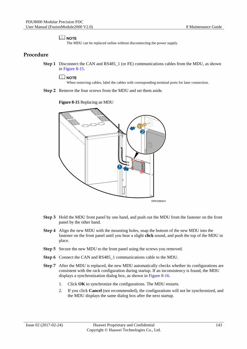
PDU8000 Modular Precision PDC
User Manual (FusionModule2000 V2.0) 8 Maintenance Guide
Issue 02 (2017-02-24) Huawei Proprietary and Confidential
Copyright © Huawei Technologies Co., Ltd.
143
The MDU can be replaced online without disconnecting the power supply.
Procedure
Step 1 Disconnect the CAN and RS485_1 (or FE) communications cables from the MDU, as shown
in Figure 8-15.
When removing cables, label the cables with corresponding terminal ports for later connection.
Step 2 Remove the four screws from the MDU and set them aside.
Figure 8-15 Replacing an MDU
Step 3 Hold the MDU front panel by one hand, and push out the MDU from the fastener on the front
panel by the other hand.
Step 4 Align the new MDU with the mounting holes, snap the bottom of the new MDU into the
fastener on the front panel until you hear a slight click sound, and push the top of the MDU in
place.
Step 5 Secure the new MDU to the front panel using the screws you removed.
Step 6 Connect the CAN and RS485_1 communications cable to the MDU.
Step 7 After the MDU is replaced, the new MDU automatically checks whether its configurations are
consistent with the rack configuration during startup. If an inconsistency is found, the MDU
displays a synchronization dialog box, as shown in Figure 8-16.
1. Click OK to synchronize the configurations. The MDU restarts.
2. If you click Cancel (not recommended), the configurations will not be synchronized, and
the MDU displays the same dialog box after the next startup.
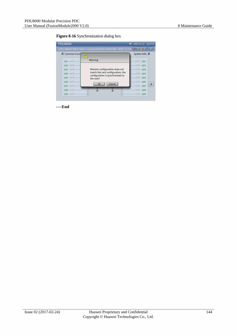
PDU8000 Modular Precision PDC
User Manual (FusionModule2000 V2.0) 8 Maintenance Guide
Issue 02 (2017-02-24) Huawei Proprietary and Confidential
Copyright © Huawei Technologies Co., Ltd.
144
Figure 8-16 Synchronization dialog box
----End
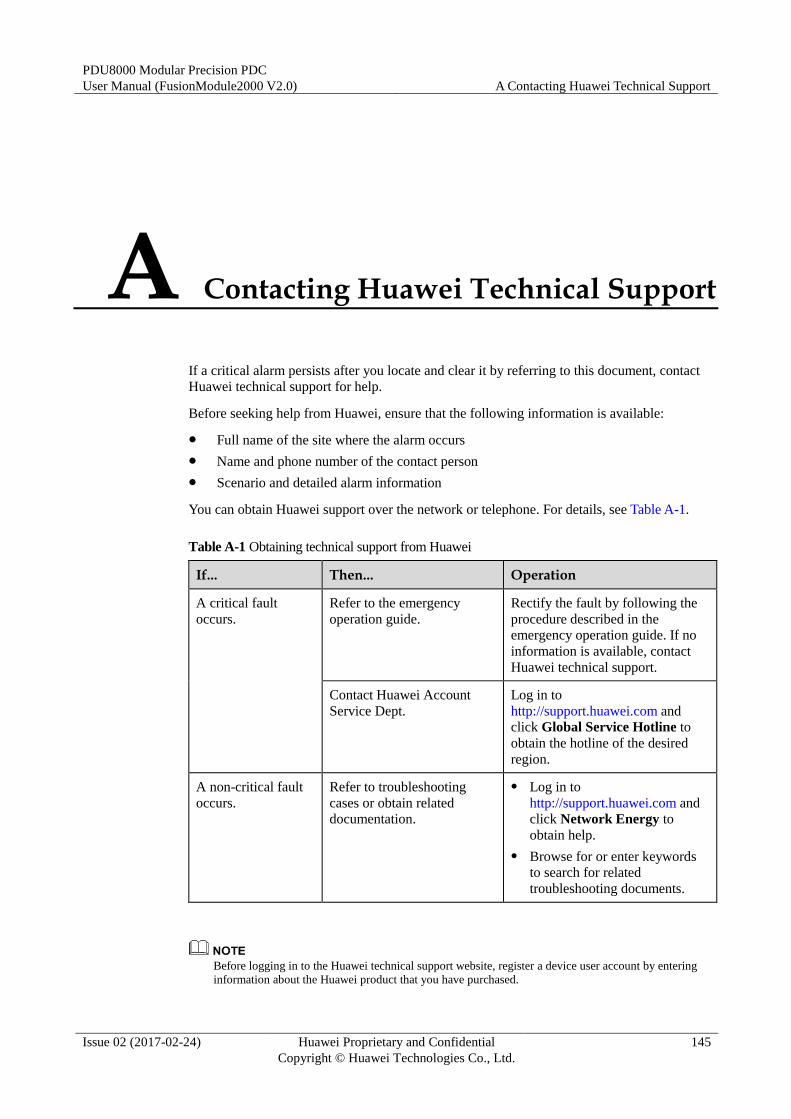
PDU8000 Modular Precision PDC
User Manual (FusionModule2000 V2.0) A Contacting Huawei Technical Support
Issue 02 (2017-02-24) Huawei Proprietary and Confidential
Copyright © Huawei Technologies Co., Ltd.
145
A Contacting Huawei Technical Support
If a critical alarm persists after you locate and clear it by referring to this document, contact
Huawei technical support for help.
Before seeking help from Huawei, ensure that the following information is available:
Full name of the site where the alarm occurs
Name and phone number of the contact person
Scenario and detailed alarm information
You can obtain Huawei support over the network or telephone. For details, see Table A-1.
Table A-1 Obtaining technical support from Huawei
If... Then... Operation
A critical fault
occurs.
Refer to the emergency
operation guide.
Rectify the fault by following the
procedure described in the
emergency operation guide. If no
information is available, contact
Huawei technical support.
Contact Huawei Account
Service Dept.
Log in to
http://support.huawei.com and
click Global Service Hotline to
obtain the hotline of the desired
region.
A non-critical fault
occurs.
Refer to troubleshooting
cases or obtain related
documentation.
Log in to
http://support.huawei.com and
click Network Energy to
obtain help.
Browse for or enter keywords
to search for related
troubleshooting documents.
Before logging in to the Huawei technical support website, register a device user account by entering
information about the Huawei product that you have purchased.
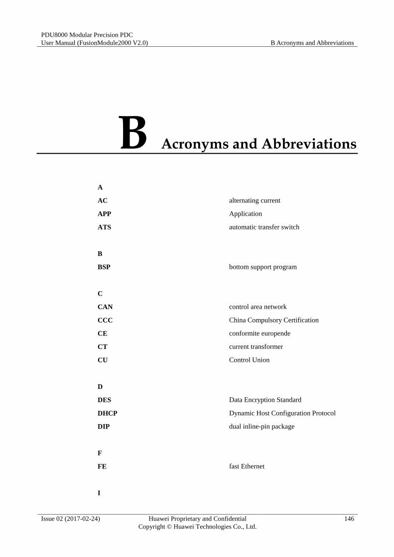
PDU8000 Modular Precision PDC
User Manual (FusionModule2000 V2.0) B Acronyms and Abbreviations
Issue 02 (2017-02-24) Huawei Proprietary and Confidential
Copyright © Huawei Technologies Co., Ltd.
146
B Acronyms and Abbreviations
A
AC alternating current
APP Application
ATS automatic transfer switch
B
BSP bottom support program
C
CAN control area network
CCC China Compulsory Certification
CE conformite europende
CT current transformer
CU Control Union
D
DES Data Encryption Standard
DHCP Dynamic Host Configuration Protocol
DIP dual inline-pin package
F
FE fast Ethernet
I
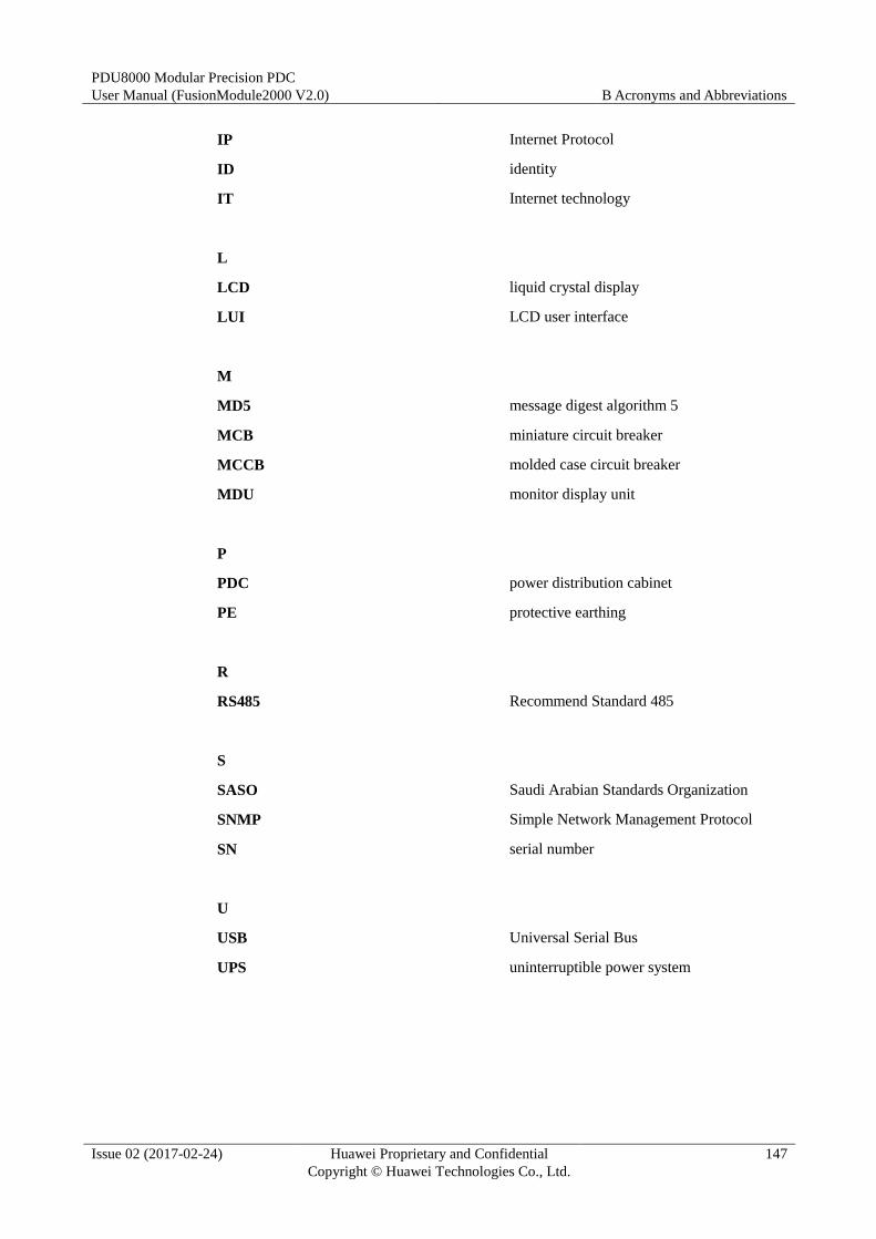
PDU8000 Modular Precision PDC
User Manual (FusionModule2000 V2.0) B Acronyms and Abbreviations
Issue 02 (2017-02-24) Huawei Proprietary and Confidential
Copyright © Huawei Technologies Co., Ltd.
147
IP Internet Protocol
ID identity
IT Internet technology
L
LCD liquid crystal display
LUI LCD user interface
M
MD5 message digest algorithm 5
MCB miniature circuit breaker
MCCB molded case circuit breaker
MDU monitor display unit
P
PDC power distribution cabinet
PE protective earthing
R
RS485 Recommend Standard 485
S
SASO Saudi Arabian Standards Organization
SNMP Simple Network Management Protocol
SN serial number
U
USB Universal Serial Bus
UPS uninterruptible power system
Related Documents