USER MANUAL FOR GMT FELLING GRAPPLE (all models, including TTC) Serial numbers: GMT035-765 and up GMT050-255 and up Release date: May-2021

Welcome message from author
This document is posted to help you gain knowledge. Please leave a comment to let me know what you think about it! Share it to your friends and learn new things together.
Transcript

USER MANUAL FOR GMT FELLING GRAPPLE (all models, including TTC)
Serial numbers:
GMT035-765 and up GMT050-255 and up
Release date: May-2021
GMT035 & GMT050 (including TTC models) User manual
2
Contents 1. Introduction ............................................................................................................................. 4 1.1 Use of this manual .................................................................................................................... 4 1.2 Safety guidelines ...................................................................................................................... 4 1.2.1 Personal protection .................................................................................................................. 4 1.2.2 Working conditions .................................................................................................................. 4 1.2.3 Which GMT felling grapple model ............................................................................................ 5 2. How to prepare for use ........................................................................................................... 6 2.1 Serial number ........................................................................................................................... 6 2.2 Transport .................................................................................................................................. 6 2.3 Connecting the GMT felling grapple ........................................................................................ 7 2.4 Connecting the GMT felling grapple with TTC ......................................................................... 9 2.5 Installing the drain valve .......................................................................................................... 9 2.6 Installation on Telehandler ....................................................................................................10 2.7 Operating pressure .................................................................................................................11 2.7.1 Hydraulic schematic for install of GMT felling grapple ..........................................................11 2.7.2 Hydraulic schematic for install of GMT felling grapple with TTC ...........................................12 3. How to operate ......................................................................................................................13 3.1 Application GMT felling grapple .............................................................................................13 3.2 Application GMT felling grapple with TTC ..............................................................................13 3.3 Preparation of tree job ...........................................................................................................13 3.3.1 Introduction ............................................................................................................................13 3.3.2 Limitations ..............................................................................................................................14 3.3.2.1 Maximum load........................................................................................................................14 3.3.2.2 Maximum tree height .............................................................................................................15 3.3.2.3 Lifting reference GMT035 ......................................................................................................16 3.3.2.4 Lifting reference GMT050 ......................................................................................................17 3.3.3 Making a double cut ...............................................................................................................18 3.3.4 Tree Felling Plan (TFP) ............................................................................................................19 3.3.4.1 Layout of working area ...........................................................................................................19 3.3.4.2 Risk zone .................................................................................................................................19 3.3.4.3 Safety zone .............................................................................................................................20 3.3.4.4 Working area examples ..........................................................................................................21 3.3.5 Operation of the felling grapple .............................................................................................22 3.3.5.1 Felling a tree or branch ..........................................................................................................23 3.3.5.2 Felling a tree or branch with TTC ...........................................................................................24 4. How to maintain ....................................................................................................................28 4.1 Supplied tools .........................................................................................................................28 4.2 Daily maintenance ..................................................................................................................29 4.3 Maintenance schedule ...........................................................................................................31 4.4 Repairs / Welding ...................................................................................................................31 4.5 Replacement of saw bar and chain ........................................................................................32
GMT035 & GMT050 (including TTC models) User manual
3
4.5.1 Chain exchange ......................................................................................................................32 4.5.2 Saw blade exchange ...............................................................................................................33 4.6 Lubricants ...............................................................................................................................33 4.7 Hydraulic fluid ........................................................................................................................33 4.8 Chain oil ..................................................................................................................................34 4.9 Handle the chainsaw ..............................................................................................................35 5. How to adjust .........................................................................................................................36 5.1 Pressure adjustments .............................................................................................................36 5.1.1 Adjusting the valve block........................................................................................................36 5.1.1.1 Valve 1 ....................................................................................................................................37 5.1.1.2 Valve 10 ..................................................................................................................................37 5.1.1.3 Valve 7 ....................................................................................................................................38 5.1.1.4 Valve 6 ....................................................................................................................................38 5.1.1.5 Valve 3 ....................................................................................................................................39 5.1.1.6 Valve 8 ....................................................................................................................................40 5.1.1.7 Valve 11 ..................................................................................................................................40 5.1.2 Pressurizing the accumulator .................................................................................................41 5.1.2.1 Measuring the pressure in the accumulator ..........................................................................42 5.1.2.2 Pressurizing the accumulator in case of low pressure ...........................................................42 5.1.2.3 Excess pressure ......................................................................................................................42 5.1.3 Saw blade speed .....................................................................................................................43 5.1.4 Braking force of the TTC .........................................................................................................43 6. How to decommission ...........................................................................................................44 7. Troubleshooting .....................................................................................................................45 7.1 General ...................................................................................................................................45 7.2 Checklist .................................................................................................................................45 7.3 Common malfunctions ...........................................................................................................46 7.3.1 Sawing problems ....................................................................................................................46 7.3.2 Problems with tilt up, placing grapple in horizontal position ................................................46 7.3.3 Problems with tilt down, placing grapple in default position ................................................46 8. Technical specifications .........................................................................................................47 8.1 GMT035 ..................................................................................................................................47 8.2 GMT035 TTC ...........................................................................................................................48 8.3 Detailed hydraulic schematic GMT035 and GMT035 TTC ......................................................49 8.4 GMT050 ..................................................................................................................................50 8.5 GMT050 TTC ...........................................................................................................................51 8.6 Detailed hydraulic schematic GMT050 and GMT050 TTC ......................................................52
GMT035 & GMT050 (including TTC models) User manual
4
1. Introduction 1.1 Use of this manual This user manual has been compiled for persons who have knowledge about (energy) wood felling and tree maintenance and practical experience in the use of (forestry) machinery. Applying common sense and skills will supplement the use of this user manual. Only competent persons are permitted to operate the machinery. The operator is responsible for ensuring that no damage is caused. If the felling grapple is used by more than one person, the owner should advise the user that the instructions for use must be carefully followed. The felling grapple may only be used once all safety regulations have been thoroughly read and all components have been correctly attached/installed. Warnings and warning pictograms have been added to certain components. These texts and pictograms must be noted in order to prevent injury to persons and damage to the felling grapple.
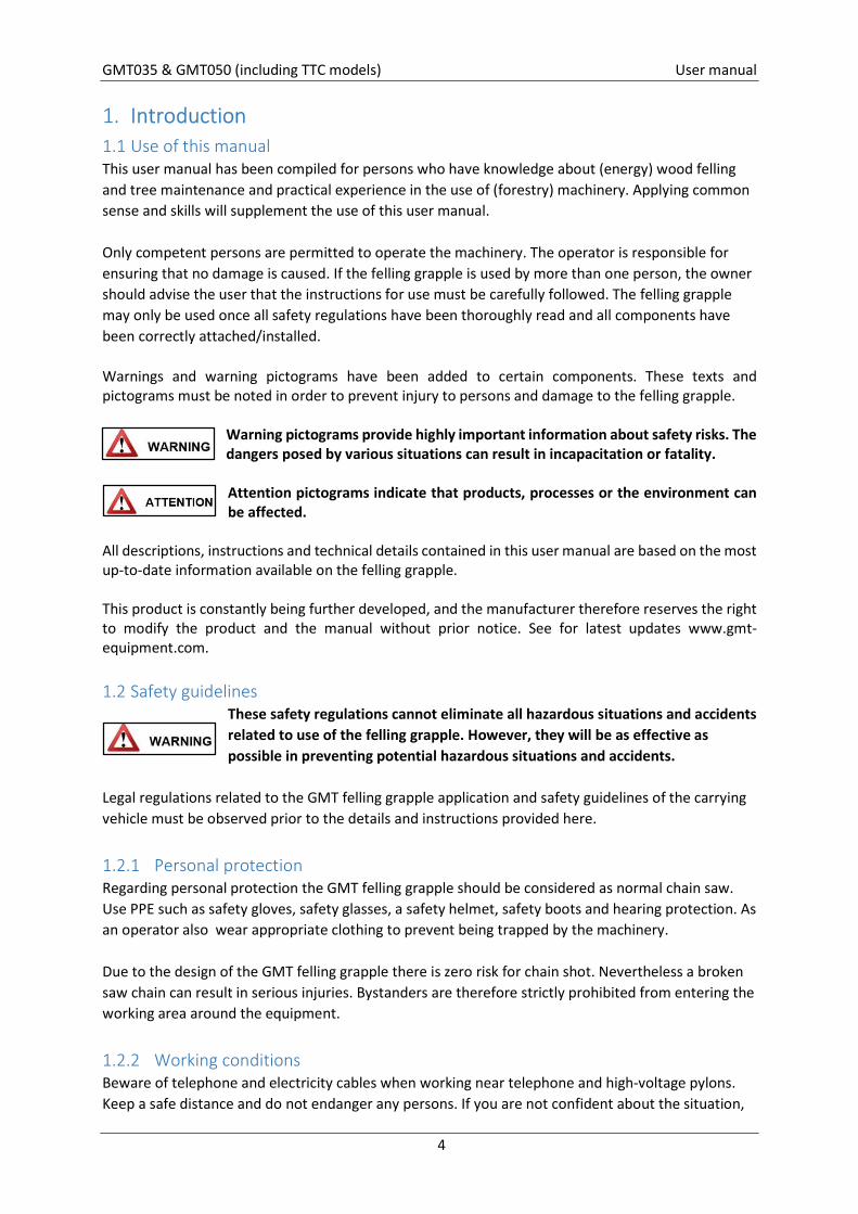
Warning pictograms provide highly important information about safety risks. The dangers posed by various situations can result in incapacitation or fatality.
Attention pictograms indicate that products, processes or the environment can be affected.
All descriptions, instructions and technical details contained in this user manual are based on the most up-to-date information available on the felling grapple. This product is constantly being further developed, and the manufacturer therefore reserves the right to modify the product and the manual without prior notice. See for latest updates www.gmt-equipment.com.
1.2 Safety guidelines These safety regulations cannot eliminate all hazardous situations and accidents related to use of the felling grapple. However, they will be as effective as possible in preventing potential hazardous situations and accidents.
Legal regulations related to the GMT felling grapple application and safety guidelines of the carrying vehicle must be observed prior to the details and instructions provided here.
1.2.1 Personal protection Regarding personal protection the GMT felling grapple should be considered as normal chain saw. Use PPE such as safety gloves, safety glasses, a safety helmet, safety boots and hearing protection. As an operator also wear appropriate clothing to prevent being trapped by the machinery. Due to the design of the GMT felling grapple there is zero risk for chain shot. Nevertheless a broken saw chain can result in serious injuries. Bystanders are therefore strictly prohibited from entering the working area around the equipment.
1.2.2 Working conditions Beware of telephone and electricity cables when working near telephone and high-voltage pylons. Keep a safe distance and do not endanger any persons. If you are not confident about the situation,
GMT035 & GMT050 (including TTC models) User manual
5
contact the local electricity operator. If you are forced to abandon the equipment, your own safety is imperative. Do not pause to secure the machinery. Leave the scene of potential electrical danger as quickly as possible. Never run, but move forward by pressing your legs together and walking away. Various weather conditions can affect use of the felling grapple. Such conditions include wind, snow and/or storms. Weather conditions must be taken into account before use of the felling grapple. Observe all instructions contained in the user manual of the felling grapple, the crane and the carrying vehicle in order to prevent hazardous situations and avoid endangering any persons. The carrying vehicle with the felling grapple may in no way whatsoever be operated or repaired if the operator is under the influence of alcohol and/or narcotics. Rest the felling grapple on a firm surface when work is complete or when temporarily turning off the carrying vehicle.
1.2.3 Which GMT felling grapple model This user manual is applicable for all GMT felling grapple models. If instructions or guidelines are applicable for a specific model/type then this will be mentioned in text clearly.
GMT035 & GMT050 (including TTC models) User manual
6
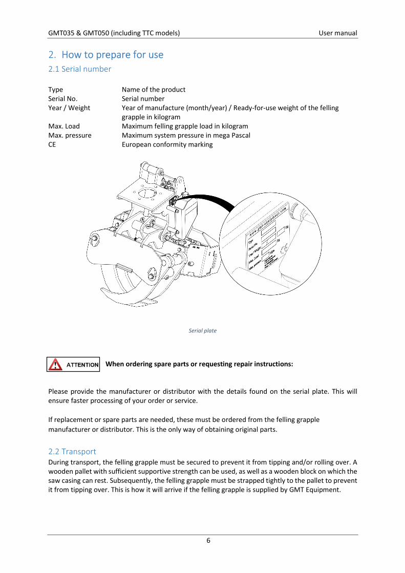
2. How to prepare for use 2.1 Serial number Type Name of the product Serial No. Serial number Year / Weight Year of manufacture (month/year) / Ready-for-use weight of the felling grapple in kilogram Max. Load Maximum felling grapple load in kilogram Max. pressure Maximum system pressure in mega Pascal CE European conformity marking
Serial plate
When ordering spare parts or requesting repair instructions:
Please provide the manufacturer or distributor with the details found on the serial plate. This will ensure faster processing of your order or service. If replacement or spare parts are needed, these must be ordered from the felling grapple manufacturer or distributor. This is the only way of obtaining original parts.
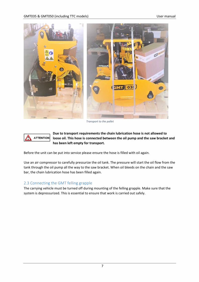
2.2 Transport During transport, the felling grapple must be secured to prevent it from tipping and/or rolling over. A wooden pallet with sufficient supportive strength can be used, as well as a wooden block on which the saw casing can rest. Subsequently, the felling grapple must be strapped tightly to the pallet to prevent it from tipping over. This is how it will arrive if the felling grapple is supplied by GMT Equipment.
GMT035 & GMT050 (including TTC models) User manual
7
Transport to the pallet
Due to transport requirements the chain lubrication hose is not allowed to loose oil. This hose is connected between the oil pump and the saw bracket and has been left empty for transport.
Before the unit can be put into service please ensure the hose is filled with oil again. Use an air compressor to carefully pressurize the oil tank. The pressure will start the oil flow from the tank through the oil pump all the way to the saw bracket. When oil bleeds on the chain and the saw bar, the chain lubrication hose has been filled again.
2.3 Connecting the GMT felling grapple The carrying vehicle must be turned off during mounting of the felling grapple. Make sure that the system is depressurized. This is essential to ensure that work is carried out safely.
GMT035 & GMT050 (including TTC models) User manual
8
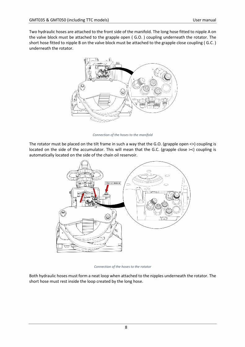
Two hydraulic hoses are attached to the front side of the manifold. The long hose fitted to nipple A on the valve block must be attached to the grapple open ( G.O. ) coupling underneath the rotator. The short hose fitted to nipple B on the valve block must be attached to the grapple close coupling ( G.C. ) underneath the rotator.
Connection of the hoses to the manifold
The rotator must be placed on the tilt frame in such a way that the G.O. (grapple open <>) coupling is located on the side of the accumulator. This will mean that the G.C. (grapple close ><) coupling is automatically located on the side of the chain oil reservoir.
Connection of the hoses to the rotator
Both hydraulic hoses must form a neat loop when attached to the nipples underneath the rotator. The short hose must rest inside the loop created by the long hose.
GMT035 & GMT050 (including TTC models) User manual
9
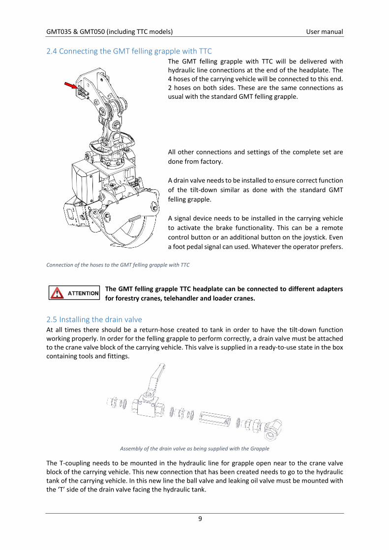
2.4 Connecting the GMT felling grapple with TTC The GMT felling grapple with TTC will be delivered with hydraulic line connections at the end of the headplate. The 4 hoses of the carrying vehicle will be connected to this end. 2 hoses on both sides. These are the same connections as usual with the standard GMT felling grapple. All other connections and settings of the complete set are done from factory. A drain valve needs to be installed to ensure correct function of the tilt-down similar as done with the standard GMT felling grapple. A signal device needs to be installed in the carrying vehicle to activate the brake functionality. This can be a remote control button or an additional button on the joystick. Even a foot pedal signal can used. Whatever the operator prefers.
Connection of the hoses to the GMT felling grapple with TTC
The GMT felling grapple TTC headplate can be connected to different adapters for forestry cranes, telehandler and loader cranes.
2.5 Installing the drain valve At all times there should be a return-hose created to tank in order to have the tilt-down function working properly. In order for the felling grapple to perform correctly, a drain valve must be attached to the crane valve block of the carrying vehicle. This valve is supplied in a ready-to-use state in the box containing tools and fittings.
Assembly of the drain valve as being supplied with the Grapple
The T-coupling needs to be mounted in the hydraulic line for grapple open near to the crane valve block of the carrying vehicle. This new connection that has been created needs to go to the hydraulic tank of the carrying vehicle. In this new line the ball valve and leaking oil valve must be mounted with the ‘T’ side of the drain valve facing the hydraulic tank.
GMT035 & GMT050 (including TTC models) User manual
10
When a main manifold with a H-port connection in neutral position is present on the carrying vehicle than the drain valve is not needed to be installed. See the hydraulic schematic as well.
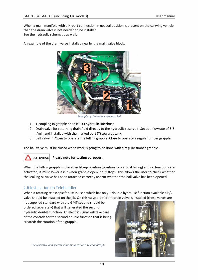
An example of the drain valve installed nearby the main valve block.
Example of the drain valve installed
1. T-coupling in grapple open (G.O.) hydraulic line/hose 2. Drain valve for returning drain fluid directly to the hydraulic reservoir. Set at a flowrate of 5-6
l/min and installed with the marked port (T) towards tank. 3. Ball valve Open to operate the felling grapple. Close to operate a regular timber grapple.
The ball valve must be closed when work is going to be done with a regular timber grapple.
Please note for testing purposes:
When the felling grapple is placed in tilt-up position (position for vertical felling) and no functions are activated, it must lower itself when grapple open input stops. This allows the user to check whether the leaking oil valve has been attached correctly and/or whether the ball valve has been opened.
2.6 Installation on Telehandler When a rotating telescopic forklift is used which has only 1 double hydraulic function available a 6/2 valve should be installed on the jib. On this valve a different drain valve is installed (these valves are not supplied standard with the GMT set and should be ordered separately) that will generated the second hydraulic double function. An electric signal will take care of the controls for the second double function that is being created: the rotation of the grapple.
The 6/2 valve and special valve mounted on a telehandler jib
GMT035 & GMT050 (including TTC models) User manual
11
2.7 Operating pressure For certain carrying vehicles, a manometer must be used to measure the operating pressure in order to adjust the felling grapple for use. Check the operating pressure of the base appliance. Further details can be found in the technical specifications of the base appliance. The maximum permissible operating pressure for the felling grapple is 250 bar [25Mpa].
A rise in pressure inside/on the system can result in damage to the felling grapple and can increase the risk of accidents!
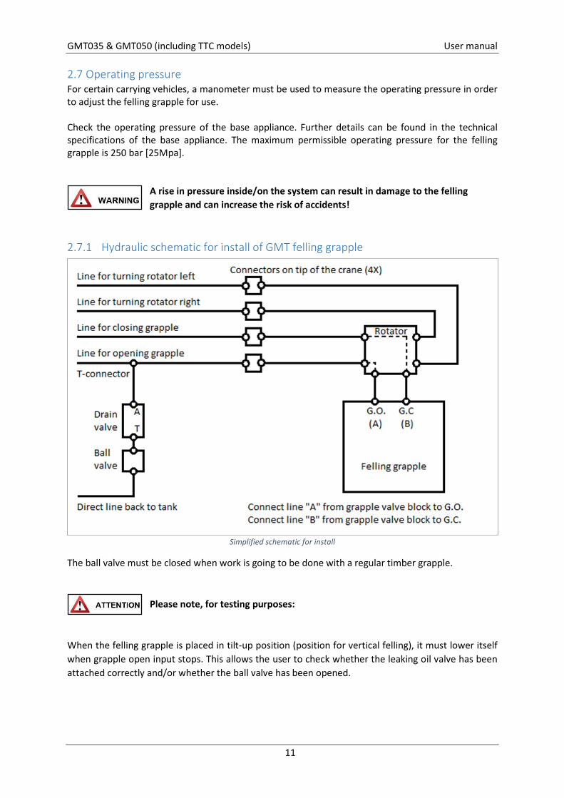
2.7.1 Hydraulic schematic for install of GMT felling grapple
Simplified schematic for install
The ball valve must be closed when work is going to be done with a regular timber grapple.
Please note, for testing purposes:
When the felling grapple is placed in tilt-up position (position for vertical felling), it must lower itself when grapple open input stops. This allows the user to check whether the leaking oil valve has been attached correctly and/or whether the ball valve has been opened.
GMT035 & GMT050 (including TTC models) User manual
12
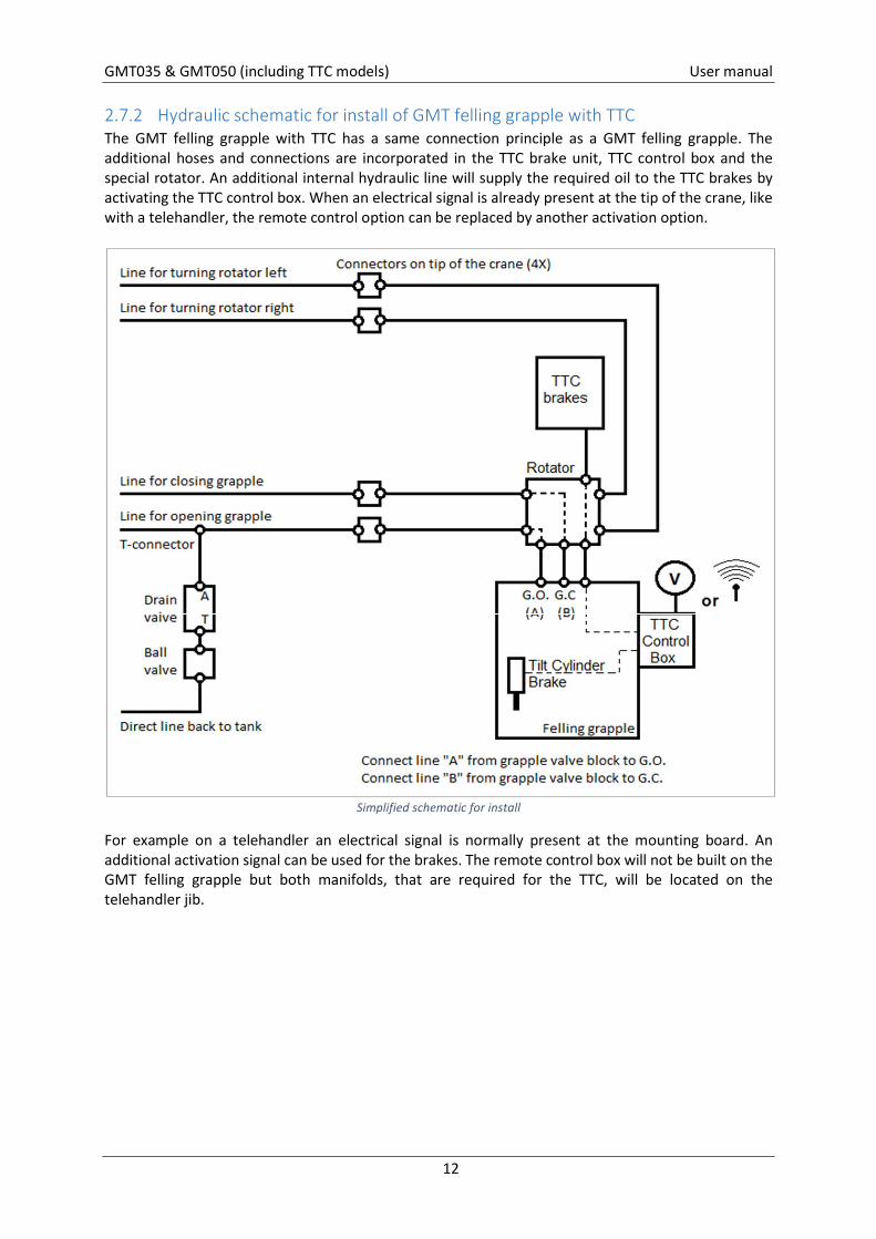
2.7.2 Hydraulic schematic for install of GMT felling grapple with TTC The GMT felling grapple with TTC has a same connection principle as a GMT felling grapple. The additional hoses and connections are incorporated in the TTC brake unit, TTC control box and the special rotator. An additional internal hydraulic line will supply the required oil to the TTC brakes by activating the TTC control box. When an electrical signal is already present at the tip of the crane, like with a telehandler, the remote control option can be replaced by another activation option.
Simplified schematic for install
For example on a telehandler an electrical signal is normally present at the mounting board. An additional activation signal can be used for the brakes. The remote control box will not be built on the GMT felling grapple but both manifolds, that are required for the TTC, will be located on the telehandler jib.
GMT035 & GMT050 (including TTC models) User manual
13
3. How to operate 3.1 Application GMT felling grapple The GMT felling grapple is a timber grapple with a saw function, consisting of a tilt frame, a grapple frame and a saw casing. The tilting grapple frame ensures that both horizontal and vertical timber can be cut. The following tasks can be carried out with the felling grapple;
Maintenance to or felling of trees Cutting of firewood/residual wood Clearing of storm damage Mechanized pruning of trees
When performing these tasks on any wood growing horizontal to the ground (usually considered limbs rather than trunk wood) the maximum cutting diameter must be taken into account in all cases. Using the proper techniques and understanding how to apply them to individual trees is the key to felling any tree safely.
3.2 Application GMT felling grapple with TTC Besides the already proven concept of GMT felling grapples the GMT felling grapple with TTC is an addition to the functionality. With the TTC it is possible to hold each branch in any position by means of activating the hydraulic brake for the rotation of the link between the crane head and the rotator. At the same time the tilt-cylinder will be hold in position as well. Basically there is no limit in holding the cut branches therefore GMT has limited the braking capacity and will be always lower than the maximum allowable forces on the crane beams. The TTC has been developed to be used in situations when:
dead or sick trees needs to be removed and there is no room for branches to break off and fall down
the felling grapple is not allowed to swing down after cutting because the branch could: o get tangled in other tree parts o damage below situated obstacles o get in touch with overhanging electrical cables
3.3 Preparation of tree job 3.3.1 Introduction Meccanized felling of trees is a relatively new and growing business. More traditional guidelines do not fit with the capabilities of the GMT felling grapple. Therefor this manual has the objective to support (sub-)contractors as well as clients to determine how to work safe and efficient with the GMT felling grapple.
Risk zone = Zone within working area where nobody is allowed Safety zone = zone within working area where only authorized personnel is allowed with
appropriate protection Working area = Risk zone + Safety zone
GMT035 & GMT050 (including TTC models) User manual
14
3.3.2 Limitations 3.3.2.1 Maximum load The greatest danger is underestimating the weight of the tree or branch being sawn. After sawing, the load becomes a hanging load for the machine! At all times the maximum load mentioned in the load chart of the crane is decisive! A common used method to determine the maximum load that can be cut is:
Find the maximum load mentioned in the load chart of the crane and subtract the weight of the felling grapple set.
Then 50% of the weight that is left will be the maximum load of the limb or branch which is allowed to be removed when the load becomes a hanging load for the crane after cutting.
The maximum load of the GMT035 felling grapple is 1.500kg/3.300lbs and for the GMT050 felling grapple the maximum load is 2.500kg/5500lbs. The maximum length which may be cut is limited to 6 meter (20 feet) or shorter when the maximal allowed weight has been reached first.
When a TTC is used:
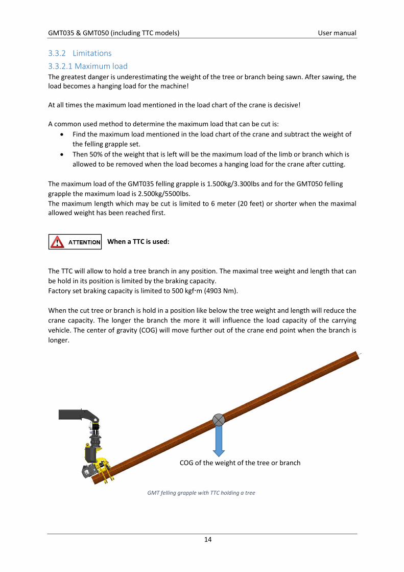
The TTC will allow to hold a tree branch in any position. The maximal tree weight and length that can be hold in its position is limited by the braking capacity. Factory set braking capacity is limited to 500 kgfm (4903 Nm). When the cut tree or branch is hold in a position like below the tree weight and length will reduce the crane capacity. The longer the branch the more it will influence the load capacity of the carrying vehicle. The center of gravity (COG) will move further out of the crane end point when the branch is longer.
GMT felling grapple with TTC holding a tree
COG of the weight of the tree or branch
GMT035 & GMT050 (including TTC models) User manual
15
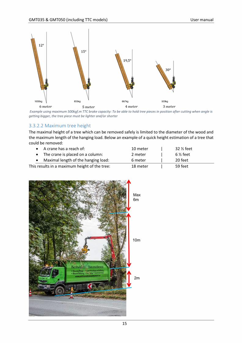
Example using maximum 500kgf.m TTC brake capacity: To be able to hold tree pieces in position after cutting when angle is getting bigger, the tree piece must be lighter and/or shorter
3.3.2.2 Maximum tree height The maximal height of a tree which can be removed safely is limited to the diameter of the wood and the maximum length of the hanging load. Below an example of a quick height estimation of a tree that could be removed:
A crane has a reach of: 10 meter | 32 ½ feet The crane is placed on a column: 2 meter | 6 ½ feet Maximal length of the hanging load: 6 meter | 20 feet
This results in a maximum height of the tree: 18 meter | 59 feet
GMT035 & GMT050 (including TTC models) User manual
16
3.3.2.3 Lifting reference GMT035 Generally this section should be used as reference when sawing branches at height using a rotating telescopic forklift or a truck/mobile loader crane. The greatest danger involves underestimating the weight of the tree or branch being cut. Once it has been cut, the tree or branch becomes a suspended load that the machine has to support!
Besides the weight of the tree or branch, also take the constant weight of a possible jib and rotator with felling grapple into account. This information is applicable for all GMT felling grapple models.
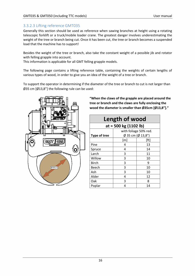
The following page contains a lifting reference table, containing the weights of certain lengths of various types of wood, in order to give you an idea of the weight of a tree or branch. To support the operator in determining if the diameter of the tree or branch to cut is not larger than Ø35 cm [Ø13,8”] the following rule can be used:
“When the claws of the grapple are placed around the tree or branch and the claws are fully enclosing the wood the diameter is smaller than Ø35cm [Ø13,8”].”
Length of wood at ≈ 500 kg (1102 lb)
Type of tree with foliage 50% red.
Ø 35 cm (Ø 13,8") [m] [ft] Pine 4 13 Spruce 4 14 Larch 3 11 Willow 3 10 Birch 3 9 Beech 3 10 Ash 3 10 Alder 4 12 Oak 3 8 Poplar 4 14
GMT035 & GMT050 (including TTC models) User manual
17
The values in the table are indications only.
The load charts of the crane and carrying vehicle as well as the maximum allowed length of the hanging load are at all times decisive. Lifting reference table
Lifting reference (Metric system) Length for 500 kg stem Length for 1000 kg stem
Type of tree
Average density of 1 m3 fresh
green wood
Weight stem Ø 13,8"
[Ø 35cm]
tree without foliage Ø 13,8"
[Ø 35cm]
with foliage (50% red.)
Ø 13,8" [Ø 35cm]
tree without foliage Ø 13,8"
[Ø 35cm]
with foliage (50% red.)
Ø 13,8" [Ø 35cm]
[kg/m3] [kg/m] [m] [m] [m] [m] Pine 673 65 8 4 15 8 Spruce 625 60 8 4 17 8 Larch 769 74 7 3 14 7 Willow 865 83 6 3 12 6 Birch 913 88 6 3 11 6 Beech 865 83 6 3 12 6 Ash 849 82 6 3 12 6 Alder 721 69 7 4 14 7 Oak 1009 97 5 3 10 5 Poplar 609 59 9 4 17 9
Origin: Moisture Content and Weight. [online] Available at: https://www.engineeringtoolbox.com/weigt-wood-d_821.html [Accessed 25 Apr 2019]
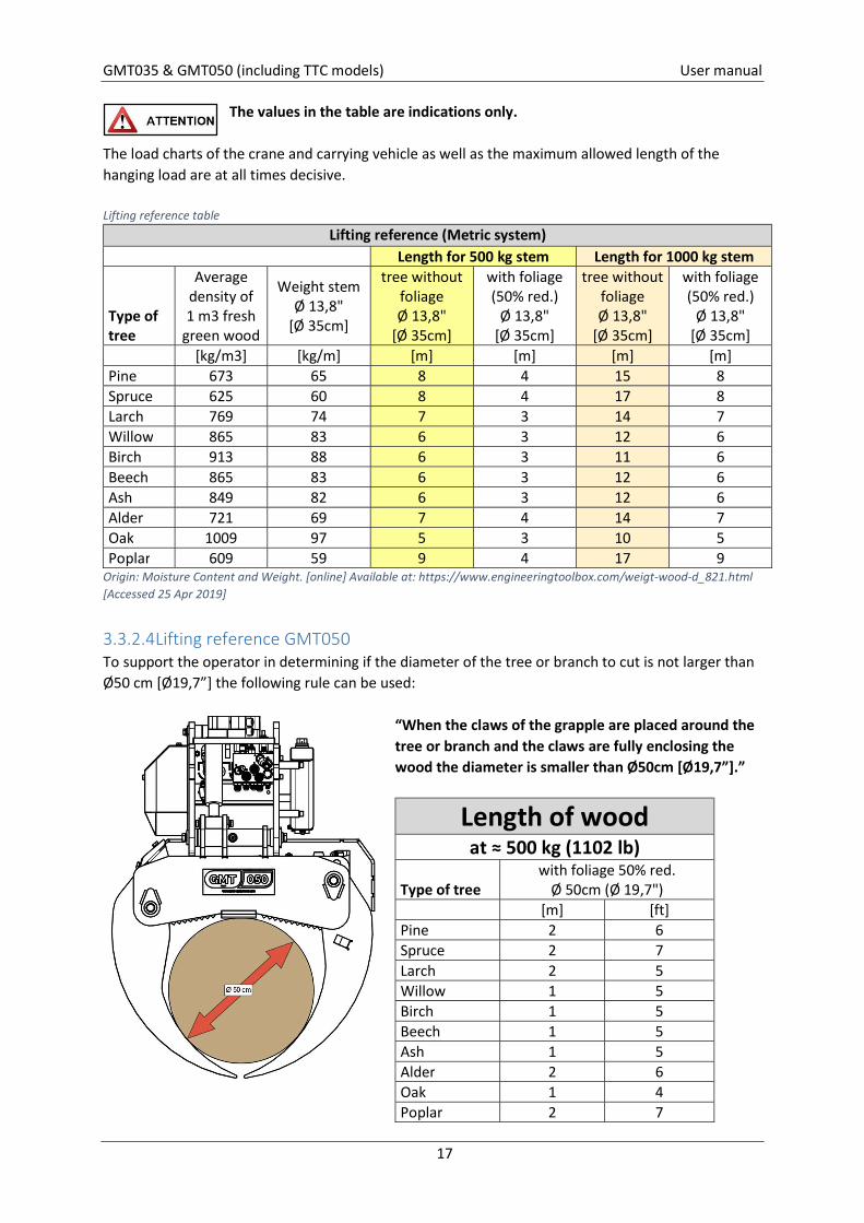
3.3.2.4 Lifting reference GMT050 To support the operator in determining if the diameter of the tree or branch to cut is not larger than Ø50 cm [Ø19,7”] the following rule can be used:
“When the claws of the grapple are placed around the tree or branch and the claws are fully enclosing the wood the diameter is smaller than Ø50cm [Ø19,7”].”
Length of wood at ≈ 500 kg (1102 lb)
Type of tree with foliage 50% red.
Ø 50cm (Ø 19,7") [m] [ft] Pine 2 6 Spruce 2 7 Larch 2 5 Willow 1 5 Birch 1 5 Beech 1 5 Ash 1 5 Alder 2 6 Oak 1 4 Poplar 2 7
GMT035 & GMT050 (including TTC models) User manual
18
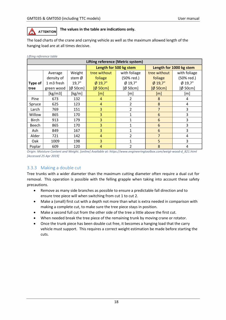
The values in the table are indications only.
The load charts of the crane and carrying vehicle as well as the maximum allowed length of the hanging load are at all times decisive. Lifting reference table
Lifting reference (Metric system) Length for 500 kg stem Length for 1000 kg stem
Type of tree
Average density of 1 m3 fresh
green wood
Weight stem Ø 19,7"
[Ø 50cm]
tree without foliage Ø 19,7"
[Ø 50cm]
with foliage (50% red.)
Ø 19,7" [Ø 50cm]
tree without foliage Ø 19,7"
[Ø 50cm]
with foliage (50% red.)
Ø 19,7" [Ø 50cm]
[kg/m3] [kg/m] [m] [m] [m] [m] Pine 673 132 4 2 8 4
Spruce 625 123 4 2 8 4 Larch 769 151 3 2 7 3
Willow 865 170 3 1 6 3 Birch 913 179 3 1 6 3 Beech 865 170 3 1 6 3
Ash 849 167 3 1 6 3 Alder 721 142 4 2 7 4 Oak 1009 198 3 1 5 3
Poplar 609 120 4 2 8 4 Origin: Moisture Content and Weight. [online] Available at: https://www.engineeringtoolbox.com/weigt-wood-d_821.html [Accessed 25 Apr 2019]
3.3.3 Making a double cut Tree trunks with a wider diameter than the maximum cutting diameter often require a dual cut for removal. This operation is possible with the felling grapple when taking into account these safety precautions.
Remove as many side branches as possible to ensure a predictable fall direction and to ensure tree piece will when switching from cut 1 to cut 2.
Make a (small) first cut with a depth not more than what is extra needed in comparison with making a complete cut, to make sure the tree piece stays in position.
Make a second full cut from the other side of the tree a little above the first cut. When needed break the tree piece of the remaining trunk by moving crane or rotator. Once the trunk piece has been double cut free, it becomes a hanging load that the carry
vehicle must support. This requires a correct weight estimation be made before starting the cuts.
GMT035 & GMT050 (including TTC models) User manual
19
3.3.4 Tree Felling Plan (TFP) Prepare your tree job carefully by making a Tree Felling Plan (TFP). Please review following topics:
Determine lay-out of working area Determine Risk zone Determine Safety zone
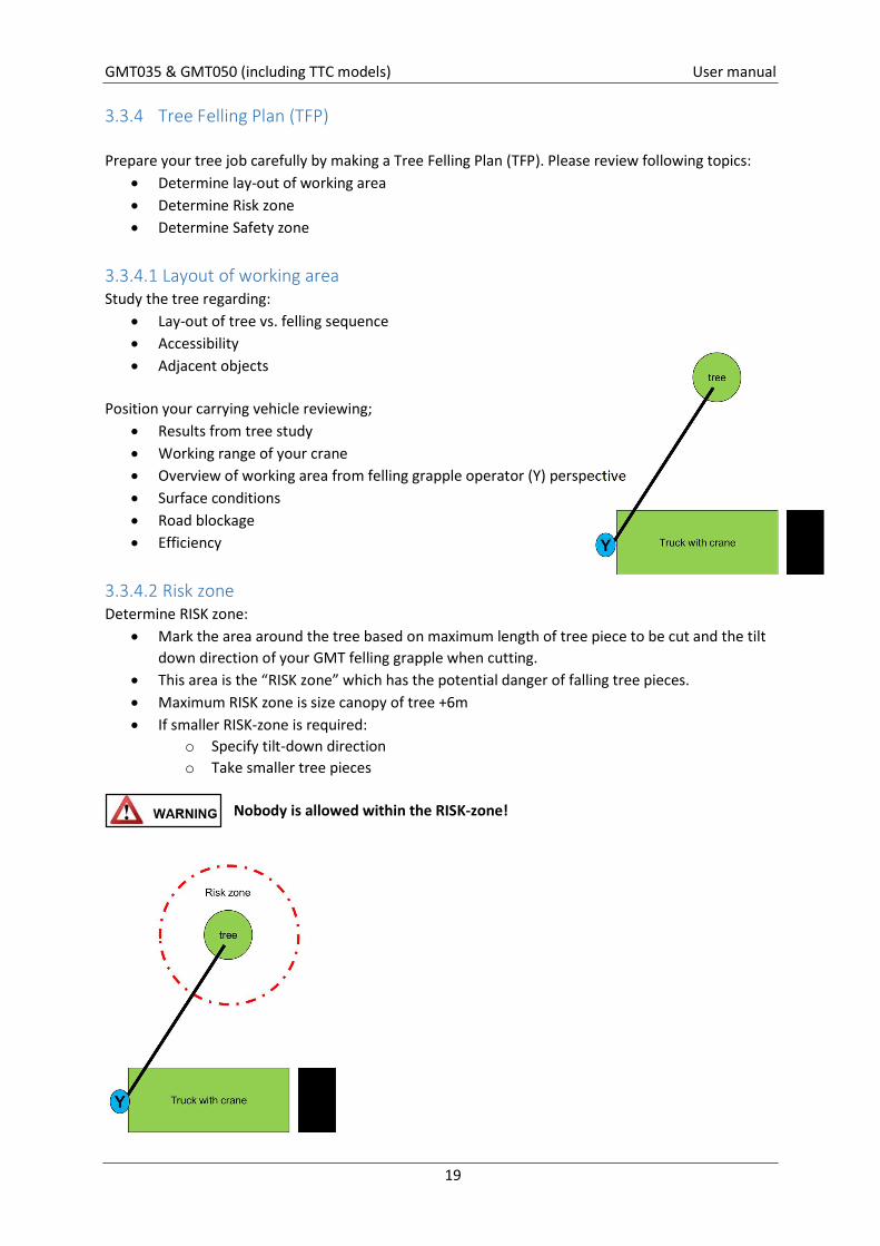
3.3.4.1 Layout of working area Study the tree regarding:
Lay-out of tree vs. felling sequence Accessibility Adjacent objects
Position your carrying vehicle reviewing;
Results from tree study Working range of your crane Overview of working area from felling grapple operator (Y) perspective Surface conditions Road blockage Efficiency
3.3.4.2 Risk zone Determine RISK zone:
Mark the area around the tree based on maximum length of tree piece to be cut and the tilt down direction of your GMT felling grapple when cutting.
This area is the “RISK zone” which has the potential danger of falling tree pieces. Maximum RISK zone is size canopy of tree +6m If smaller RISK-zone is required:
o Specify tilt-down direction o Take smaller tree pieces
Nobody is allowed within the RISK-zone!
GMT035 & GMT050 (including TTC models) User manual
20
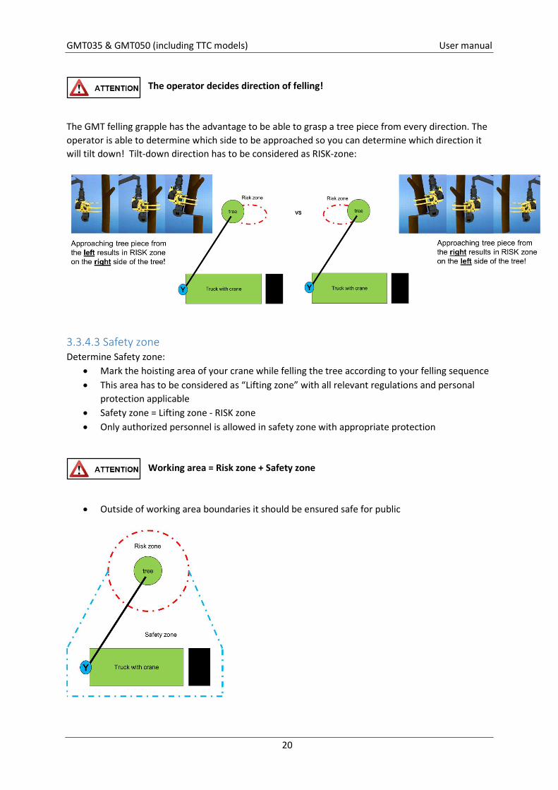
The operator decides direction of felling!
The GMT felling grapple has the advantage to be able to grasp a tree piece from every direction. The operator is able to determine which side to be approached so you can determine which direction it will tilt down! Tilt-down direction has to be considered as RISK-zone:
3.3.4.3 Safety zone Determine Safety zone:
Mark the hoisting area of your crane while felling the tree according to your felling sequence This area has to be considered as “Lifting zone” with all relevant regulations and personal
protection applicable Safety zone = Lifting zone - RISK zone Only authorized personnel is allowed in safety zone with appropriate protection
Working area = Risk zone + Safety zone
Outside of working area boundaries it should be ensured safe for public
GMT035 & GMT050 (including TTC models) User manual
21
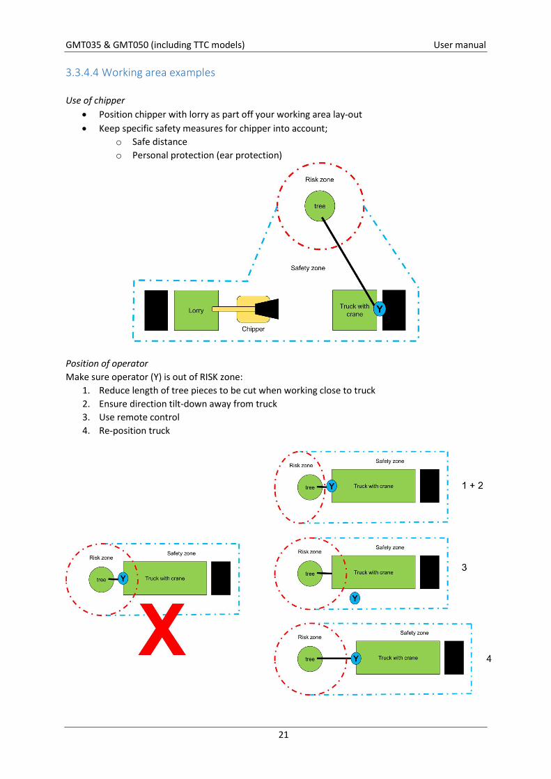
3.3.4.4 Working area examples Use of chipper
Position chipper with lorry as part off your working area lay-out Keep specific safety measures for chipper into account;
o Safe distance o Personal protection (ear protection)
Position of operator Make sure operator (Y) is out of RISK zone:
1. Reduce length of tree pieces to be cut when working close to truck 2. Ensure direction tilt-down away from truck 3. Use remote control 4. Re-position truck
GMT035 & GMT050 (including TTC models) User manual
22
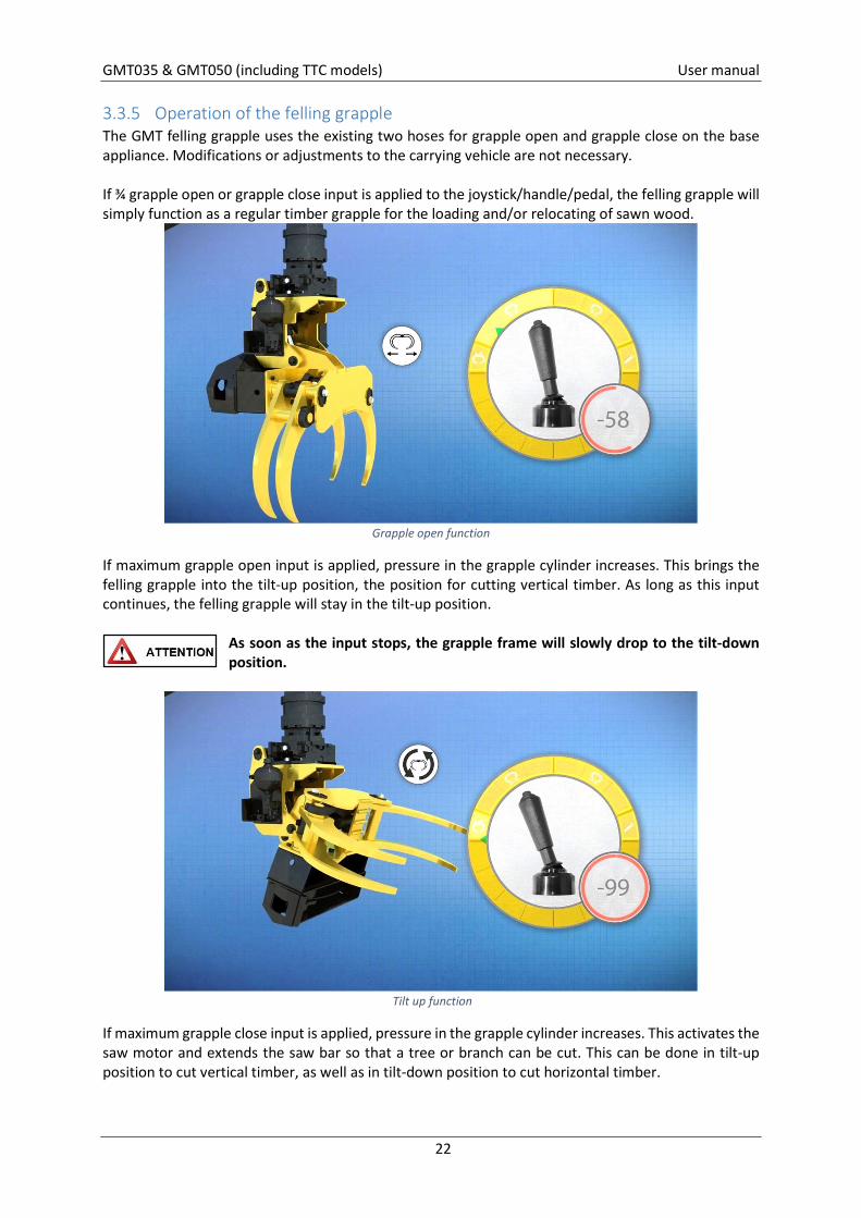
3.3.5 Operation of the felling grapple The GMT felling grapple uses the existing two hoses for grapple open and grapple close on the base appliance. Modifications or adjustments to the carrying vehicle are not necessary. If ¾ grapple open or grapple close input is applied to the joystick/handle/pedal, the felling grapple will simply function as a regular timber grapple for the loading and/or relocating of sawn wood.
Grapple open function
If maximum grapple open input is applied, pressure in the grapple cylinder increases. This brings the felling grapple into the tilt-up position, the position for cutting vertical timber. As long as this input continues, the felling grapple will stay in the tilt-up position.
As soon as the input stops, the grapple frame will slowly drop to the tilt-down position.
Tilt up function
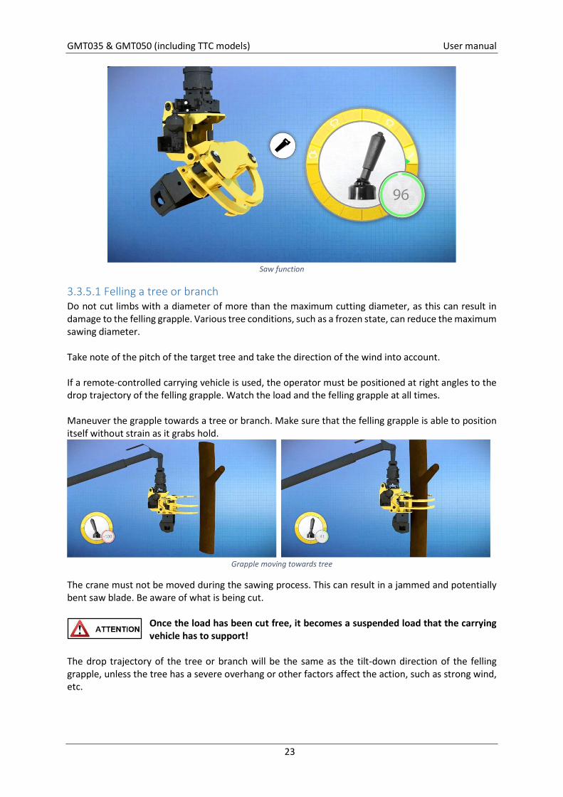
If maximum grapple close input is applied, pressure in the grapple cylinder increases. This activates the saw motor and extends the saw bar so that a tree or branch can be cut. This can be done in tilt-up position to cut vertical timber, as well as in tilt-down position to cut horizontal timber.
GMT035 & GMT050 (including TTC models) User manual
23
Saw function
3.3.5.1 Felling a tree or branch Do not cut limbs with a diameter of more than the maximum cutting diameter, as this can result in damage to the felling grapple. Various tree conditions, such as a frozen state, can reduce the maximum sawing diameter. Take note of the pitch of the target tree and take the direction of the wind into account. If a remote-controlled carrying vehicle is used, the operator must be positioned at right angles to the drop trajectory of the felling grapple. Watch the load and the felling grapple at all times. Maneuver the grapple towards a tree or branch. Make sure that the felling grapple is able to position itself without strain as it grabs hold.
Grapple moving towards tree
The crane must not be moved during the sawing process. This can result in a jammed and potentially bent saw blade. Be aware of what is being cut.
Once the load has been cut free, it becomes a suspended load that the carrying vehicle has to support!
The drop trajectory of the tree or branch will be the same as the tilt-down direction of the felling grapple, unless the tree has a severe overhang or other factors affect the action, such as strong wind, etc.
GMT035 & GMT050 (including TTC models) User manual
24
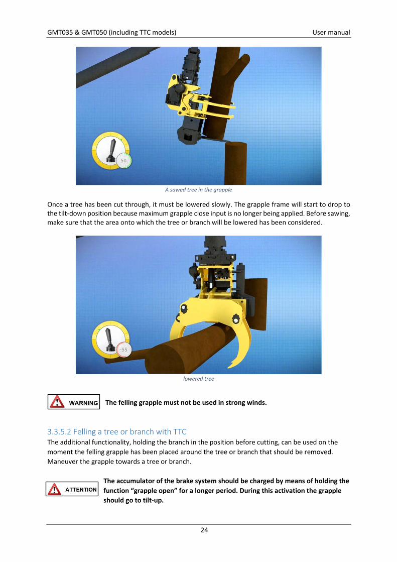
A sawed tree in the grapple
Once a tree has been cut through, it must be lowered slowly. The grapple frame will start to drop to the tilt-down position because maximum grapple close input is no longer being applied. Before sawing, make sure that the area onto which the tree or branch will be lowered has been considered.
lowered tree
The felling grapple must not be used in strong winds.
3.3.5.2 Felling a tree or branch with TTC The additional functionality, holding the branch in the position before cutting, can be used on the moment the felling grapple has been placed around the tree or branch that should be removed. Maneuver the grapple towards a tree or branch.
The accumulator of the brake system should be charged by means of holding the function “grapple open” for a longer period. During this activation the grapple should go to tilt-up.
GMT035 & GMT050 (including TTC models) User manual
25
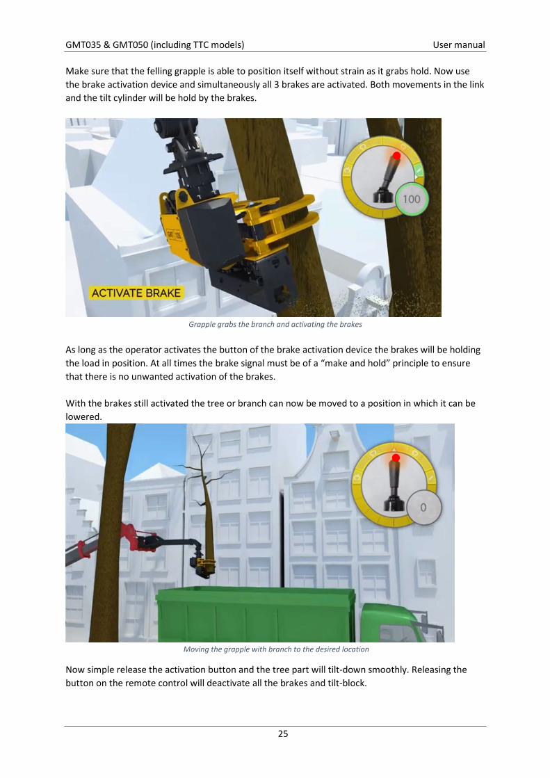
Make sure that the felling grapple is able to position itself without strain as it grabs hold. Now use the brake activation device and simultaneously all 3 brakes are activated. Both movements in the link and the tilt cylinder will be hold by the brakes.
Grapple grabs the branch and activating the brakes
As long as the operator activates the button of the brake activation device the brakes will be holding the load in position. At all times the brake signal must be of a “make and hold” principle to ensure that there is no unwanted activation of the brakes. With the brakes still activated the tree or branch can now be moved to a position in which it can be lowered.
Moving the grapple with branch to the desired location
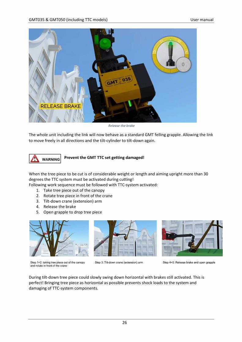
Now simple release the activation button and the tree part will tilt-down smoothly. Releasing the button on the remote control will deactivate all the brakes and tilt-block.
GMT035 & GMT050 (including TTC models) User manual
26
Release the brake
The whole unit including the link will now behave as a standard GMT felling grapple. Allowing the link to move freely in all directions and the tilt-cylinder to tilt-down again.
Prevent the GMT TTC set getting damaged!
When the tree piece to be cut is of considerable weight or length and aiming upright more than 30 degrees the TTC system must be activated during cutting! Following work sequence must be followed with TTC-system activated:
1. Take tree piece out of the canopy 2. Rotate tree piece in front of the crane 3. Tilt-down crane (extension) arm 4. Release the brake 5. Open grapple to drop tree piece
During tilt-down tree piece could slowly swing down horizontal with brakes still activated. This is perfect! Bringing tree piece as horizontal as possible prevents shock loads to the system and damaging of TTC-system components.

GMT035 & GMT050 (including TTC models) User manual
27
Get to work:
Make your TFP part of your every day job preparation Share your TFP in time with all related parties Discuss TFP with your team when starting the job Make sure all areas are marked clearly on job site Make sure your GMT felling grapple as well as all other tools and personal protection is in
good shape Review safety within Working area every cut you make!

GMT035 & GMT050 (including TTC models) User manual
28
4. How to maintain The following is required before maintenance tasks are carried out:
The carrying vehicle must be turned off and the hydraulic system must be depressurized. Depressurize the hydraulics by operating the joystick/handle/pedal once after turning off the base appliance. During maintenance, wear safety shoes, gloves, overalls and safety glasses. Avoid contact with hydraulic fluid and lubricants. These can have an irritating effect on the skin and can be harmful to health. When using these substances, instructions and guidelines from the relevant manufacturer must be read thoroughly in advance.
Beware of hydraulic fluid at operating temperature!
Do not use hydraulic fluid or lubricants for cleaning hands. These can contain steel splinters and/or additives that can damage the hands. If hydraulic fluid or lubricants have caused irritation to the hands or other body parts, consult a physician immediately! The below applies unless otherwise indicated:
From Nm to ft lb (Foot Pound) multiply by 0,74 From Nm to in lb (Inch Pound) multiply by 8,85
Torque values
4.1 Supplied tools The below tools are supplied and are intended for their corresponding tasks;
Combination spanner 30 Loosening of nuts on clamping plate for chain tensioning, chain exchange and/or saw blade exchange, opening tank plug.
Flexible screwdriver Chain tensioning Combination spanner 11/16 loosening and tightening of valve locknut Combination spanner 15 loosening and tightening of bolts cover accumulator Hex key 3/16 Valve adjustment
GMT035 & GMT050 (including TTC models) User manual
29
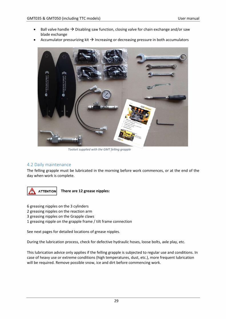
Ball valve handle Disabling saw function, closing valve for chain exchange and/or saw blade exchange
Accumulator pressurizing kit Increasing or decreasing pressure in both accumulators
Toolset supplied with the GMT felling grapple
4.2 Daily maintenance The felling grapple must be lubricated in the morning before work commences, or at the end of the day when work is complete.
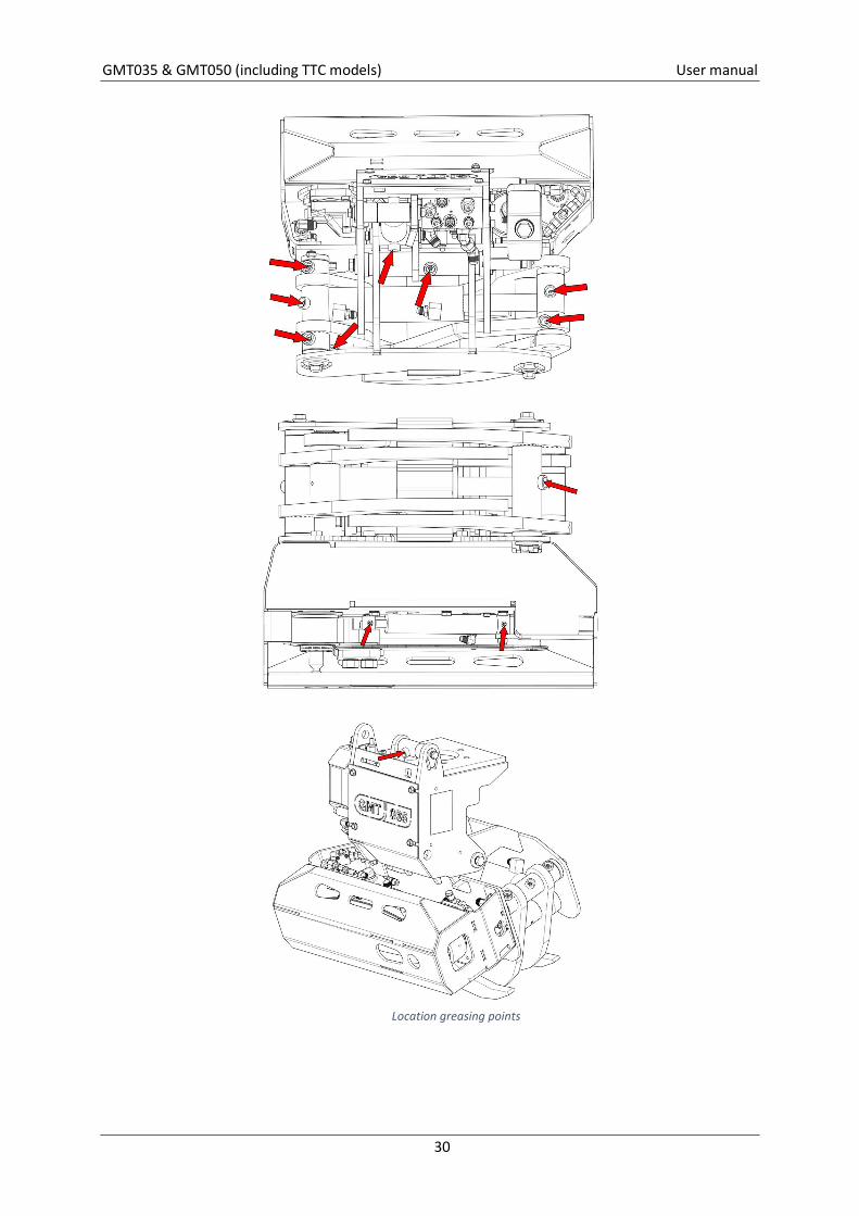
There are 12 grease nipples:
6 greasing nipples on the 3 cylinders 2 greasing nipples on the reaction arm 3 greasing nipples on the Grapple claws 1 greasing nipple on the grapple frame / tilt frame connection See next pages for detailed locations of grease nipples. During the lubrication process, check for defective hydraulic hoses, loose bolts, axle play, etc. This lubrication advice only applies if the felling grapple is subjected to regular use and conditions. In case of heavy use or extreme conditions (high temperatures, dust, etc.), more frequent lubrication will be required. Remove possible snow, ice and dirt before commencing work.
GMT035 & GMT050 (including TTC models) User manual
30
Location greasing points
GMT035 & GMT050 (including TTC models) User manual
31
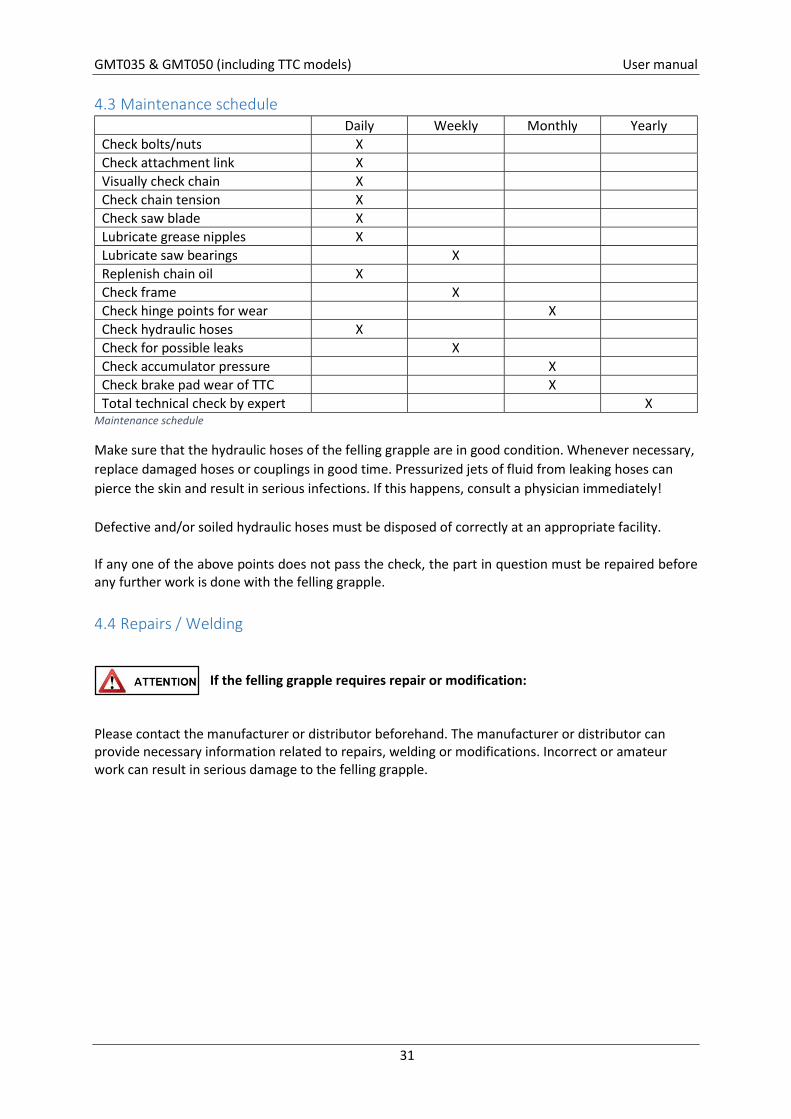
4.3 Maintenance schedule Daily Weekly Monthly Yearly Check bolts/nuts X Check attachment link X Visually check chain X Check chain tension X Check saw blade X Lubricate grease nipples X Lubricate saw bearings X Replenish chain oil X Check frame X Check hinge points for wear X Check hydraulic hoses X Check for possible leaks X Check accumulator pressure X Check brake pad wear of TTC X Total technical check by expert X
Maintenance schedule
Make sure that the hydraulic hoses of the felling grapple are in good condition. Whenever necessary, replace damaged hoses or couplings in good time. Pressurized jets of fluid from leaking hoses can pierce the skin and result in serious infections. If this happens, consult a physician immediately! Defective and/or soiled hydraulic hoses must be disposed of correctly at an appropriate facility. If any one of the above points does not pass the check, the part in question must be repaired before any further work is done with the felling grapple.
4.4 Repairs / Welding
If the felling grapple requires repair or modification:
Please contact the manufacturer or distributor beforehand. The manufacturer or distributor can provide necessary information related to repairs, welding or modifications. Incorrect or amateur work can result in serious damage to the felling grapple.
GMT035 & GMT050 (including TTC models) User manual
32
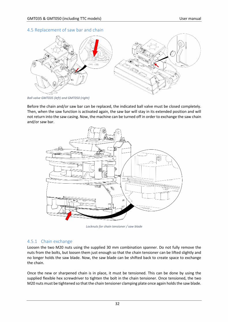
4.5 Replacement of saw bar and chain
Ball valve GMT035 (left) and GMT050 (right)
Before the chain and/or saw bar can be replaced, the indicated ball valve must be closed completely. Then, when the saw function is activated again, the saw bar will stay in its extended position and will not return into the saw casing. Now, the machine can be turned off in order to exchange the saw chain and/or saw bar.
Locknuts for chain tensioner / saw blade
4.5.1 Chain exchange Loosen the two M20 nuts using the supplied 30 mm combination spanner. Do not fully remove the nuts from the bolts, but loosen them just enough so that the chain tensioner can be lifted slightly and no longer holds the saw blade. Now, the saw blade can be shifted back to create space to exchange the chain. Once the new or sharpened chain is in place, it must be tensioned. This can be done by using the supplied flexible hex screwdriver to tighten the bolt in the chain tensioner. Once tensioned, the two M20 nuts must be tightened so that the chain tensioner clamping plate once again holds the saw blade.
GMT035 & GMT050 (including TTC models) User manual
33
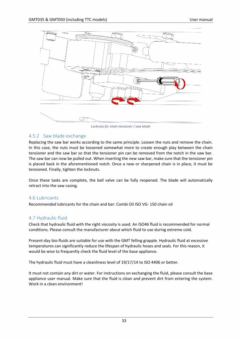
Locknuts for chain tensioner / saw blade
4.5.2 Saw blade exchange Replacing the saw bar works according to the same principle. Loosen the nuts and remove the chain. In this case, the nuts must be loosened somewhat more to create enough play between the chain tensioner and the saw bar so that the tensioner pin can be removed from the notch in the saw bar. The saw bar can now be pulled out. When inserting the new saw bar, make sure that the tensioner pin is placed back in the aforementioned notch. Once a new or sharpened chain is in place, it must be tensioned. Finally, tighten the locknuts. Once these tasks are complete, the ball valve can be fully reopened. The blade will automatically retract into the saw casing.
4.6 Lubricants Recommended lubricants for the chain and bar: Combi Oil ISO VG- 150 chain oil 4.7 Hydraulic fluid Check that hydraulic fluid with the right viscosity is used. An ISO46 fluid is recommended for normal conditions. Please consult the manufacturer about which fluid to use during extreme cold. Present-day bio-fluids are suitable for use with the GMT felling grapple. Hydraulic fluid at excessive temperatures can significantly reduce the lifespan of hydraulic hoses and seals. For this reason, it would be wise to frequently check the fluid level of the base appliance. The hydraulic fluid must have a cleanliness level of 19/17/14 to ISO 4406 or better. It must not contain any dirt or water. For instructions on exchanging the fluid, please consult the base appliance user manual. Make sure that the fluid is clean and prevent dirt from entering the system. Work in a clean environment!
GMT035 & GMT050 (including TTC models) User manual
34
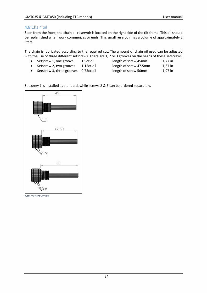
4.8 Chain oil Seen from the front, the chain oil reservoir is located on the right side of the tilt frame. This oil should be replenished when work commences or ends. This small reservoir has a volume of approximately 2 liters. The chain is lubricated according to the required cut. The amount of chain oil used can be adjusted with the use of three different setscrews. There are 1, 2 or 3 grooves on the heads of these setscrews.
Setscrew 1, one groove 1.5cc oil length of screw 45mm 1,77 in Setscrew 2, two grooves 1.15cc oil length of screw 47.5mm 1,87 in Setscrew 3, three grooves 0.75cc oil length of screw 50mm 1,97 in
Setscrew 1 is installed as standard, while screws 2 & 3 can be ordered separately.
different setscrews
GMT035 & GMT050 (including TTC models) User manual
35
4.9 Handle the chainsaw
Turn off the machine before touching the chainsaw; risk of laceration! Wear safety shoes and use appropriate tools!
Due to the design of the GMT felling grapple there is zero risk for chain shot. Modifications to the hydraulic system for the purpose of increasing the chain speed are not permitted. Nevertheless a broken saw chain can result in serious injuries. Bystanders are therefore strictly prohibited from entering the working area around the equipment.
When the chain is exchanged, it must be replaced with an inspected and sharpened chain or a new chain. Preventively renew the saw chain after every 50 hours. Only chains, saw blades and chain sprockets from recognized manufacturers may be used as replacement parts. Replace the chain and saw blade in good time. A sharpened chain reduces the risk of breaks and cracks. A new, straight saw blade will ensure that the chain does not stick. Before a new or sharpened ‘dry’ chain is installed, it must be lubricated.
A broken chain must be thoroughly checked (for breaks, deformities, cracks, etc.) before a new link is installed. You are advised to always install a new chain.
The groove of the saw blade must be in line with the chain sprocket. If necessary, the chain sprocket must be repositioned with washers to realign it with the groove. Lubricate the nose sprocket when a new saw blade is installed.
The saw function should be operated for a maximum of 15 seconds. Prolonged use of this function can possibly cause a problem with:
Burn the saw bar Increased pressure in the saw motor Burn the saw chain lubrication
Check the saw unit every two hours: Rotate the saw blade 1800 if the felling grapple is used throughout the entire day. This will
ensure that both sides of the blade are exposed to even wear. Is the chain still sharp enough? Is the chain tensioner clamping plate gripping the saw blade firmly? This will prevent a slack or
broken chain. Is the chain lubrication system functioning?
GMT035 & GMT050 (including TTC models) User manual
36
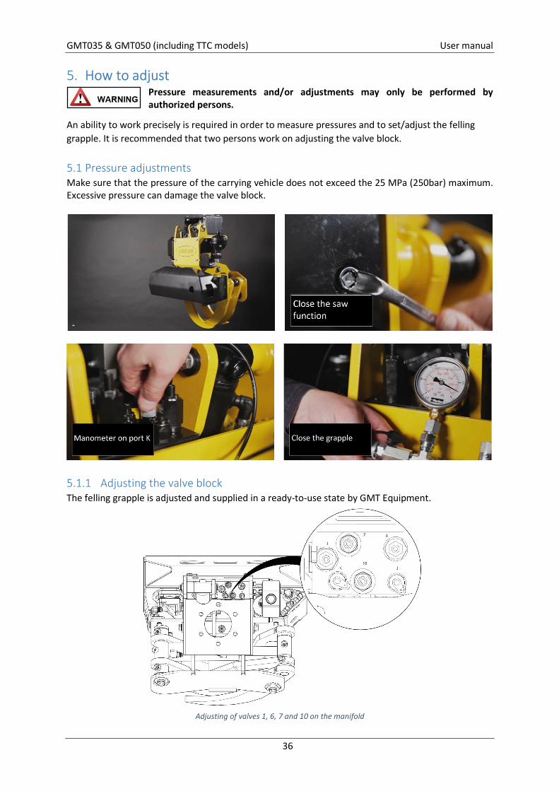
5. How to adjust Pressure measurements and/or adjustments may only be performed by authorized persons.
An ability to work precisely is required in order to measure pressures and to set/adjust the felling grapple. It is recommended that two persons work on adjusting the valve block.
5.1 Pressure adjustments Make sure that the pressure of the carrying vehicle does not exceed the 25 MPa (250bar) maximum. Excessive pressure can damage the valve block.
5.1.1 Adjusting the valve block The felling grapple is adjusted and supplied in a ready-to-use state by GMT Equipment.
Adjusting of valves 1, 6, 7 and 10 on the manifold
GMT035 & GMT050 (including TTC models) User manual
37
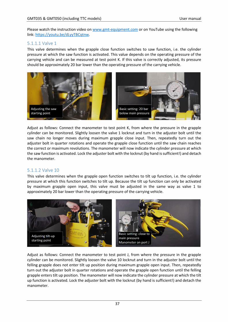
Please watch the instruction video on www.gmt-equipment.com or on YouTube using the following link: https://youtu.be/dLyyTBCqtnw.
5.1.1.1 Valve 1 This valve determines when the grapple close function switches to saw function, i.e. the cylinder pressure at which the saw function is activated. This value depends on the operating pressure of the carrying vehicle and can be measured at test point K. If this valve is correctly adjusted, its pressure should be approximately 20 bar lower than the operating pressure of the carrying vehicle.
Adjust as follows: Connect the manometer to test point K, from where the pressure in the grapple cylinder can be monitored. Slightly loosen the valve 1 locknut and turn in the adjuster bolt until the saw chain no longer moves during maximum grapple close input. Then, repeatedly turn out the adjuster bolt in quarter rotations and operate the grapple close function until the saw chain reaches the correct or maximum revolutions. The manometer will now indicate the cylinder pressure at which the saw function is activated. Lock the adjuster bolt with the locknut (by hand is sufficient!) and detach the manometer.
5.1.1.2 Valve 10 This valve determines when the grapple open function switches to tilt up function, i.e. the cylinder pressure at which this function switches to tilt up. Because the tilt up function can only be activated by maximum grapple open input, this valve must be adjusted in the same way as valve 1 to approximately 20 bar lower than the operating pressure of the carrying vehicle.
Adjust as follows: Connect the manometer to test point J, from where the pressure in the grapple cylinder can be monitored. Slightly loosen the valve 10 locknut and turn in the adjuster bolt until the felling grapple does not enter tilt up position during maximum grapple open input. Then, repeatedly turn out the adjuster bolt in quarter rotations and operate the grapple open function until the felling grapple enters tilt up position. The manometer will now indicate the cylinder pressure at which the tilt up function is activated. Lock the adjuster bolt with the locknut (by hand is sufficient!) and detach the manometer.
GMT035 & GMT050 (including TTC models) User manual
38
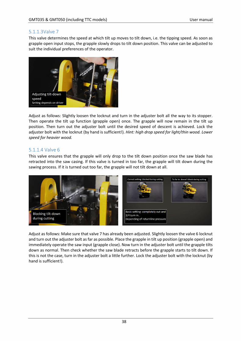
5.1.1.3 Valve 7 This valve determines the speed at which tilt up moves to tilt down, i.e. the tipping speed. As soon as grapple open input stops, the grapple slowly drops to tilt down position. This valve can be adjusted to suit the individual preferences of the operator.
Adjust as follows: Slightly loosen the locknut and turn in the adjuster bolt all the way to its stopper. Then operate the tilt up function (grapple open) once. The grapple will now remain in the tilt up position. Then turn out the adjuster bolt until the desired speed of descent is achieved. Lock the adjuster bolt with the locknut (by hand is sufficient!). Hint: high drop speed for light/thin wood. Lower speed for heavier wood.
5.1.1.4 Valve 6 This valve ensures that the grapple will only drop to the tilt down position once the saw blade has retracted into the saw casing. If this valve is turned in too far, the grapple will tilt down during the sawing process. If it is turned out too far, the grapple will not tilt down at all.
Adjust as follows: Make sure that valve 7 has already been adjusted. Slightly loosen the valve 6 locknut and turn out the adjuster bolt as far as possible. Place the grapple in tilt up position (grapple open) and immediately operate the saw input (grapple close). Now turn in the adjuster bolt until the grapple tilts down as normal. Then check whether the saw blade retracts before the grapple starts to tilt down. If this is not the case, turn in the adjuster bolt a little further. Lock the adjuster bolt with the locknut (by hand is sufficient!).
GMT035 & GMT050 (including TTC models) User manual
39
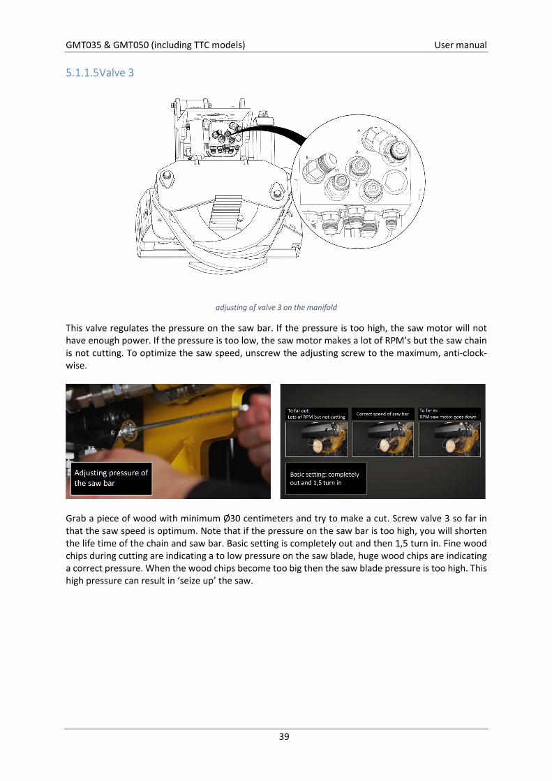
5.1.1.5 Valve 3
adjusting of valve 3 on the manifold
This valve regulates the pressure on the saw bar. If the pressure is too high, the saw motor will not have enough power. If the pressure is too low, the saw motor makes a lot of RPM’s but the saw chain is not cutting. To optimize the saw speed, unscrew the adjusting screw to the maximum, anti-clock-wise.
Grab a piece of wood with minimum Ø30 centimeters and try to make a cut. Screw valve 3 so far in that the saw speed is optimum. Note that if the pressure on the saw bar is too high, you will shorten the life time of the chain and saw bar. Basic setting is completely out and then 1,5 turn in. Fine wood chips during cutting are indicating a to low pressure on the saw blade, huge wood chips are indicating a correct pressure. When the wood chips become too big then the saw blade pressure is too high. This high pressure can result in ‘seize up’ the saw.
GMT035 & GMT050 (including TTC models) User manual
40
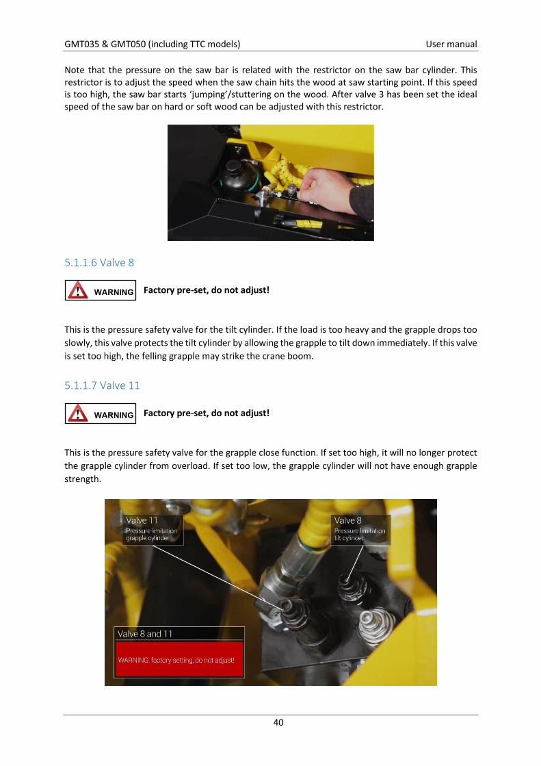
Note that the pressure on the saw bar is related with the restrictor on the saw bar cylinder. This restrictor is to adjust the speed when the saw chain hits the wood at saw starting point. If this speed is too high, the saw bar starts ‘jumping’/stuttering on the wood. After valve 3 has been set the ideal speed of the saw bar on hard or soft wood can be adjusted with this restrictor.
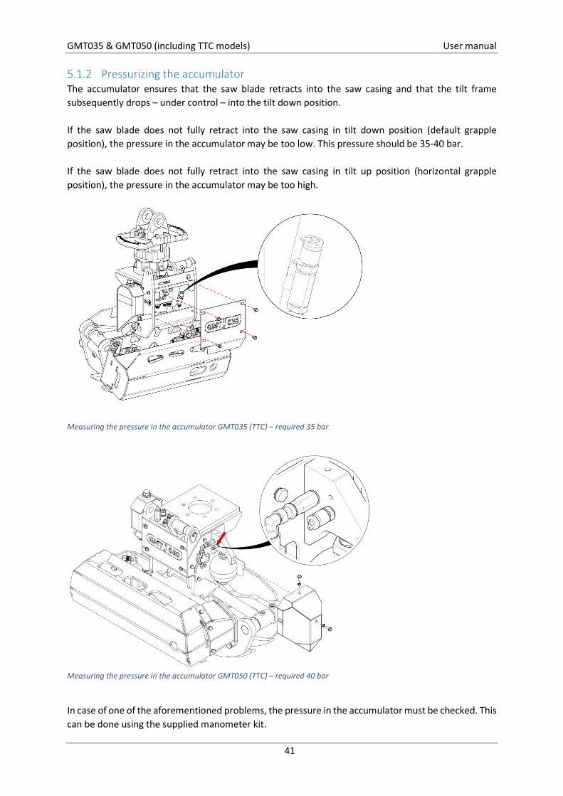
5.1.1.6 Valve 8 Factory pre-set, do not adjust!
This is the pressure safety valve for the tilt cylinder. If the load is too heavy and the grapple drops too slowly, this valve protects the tilt cylinder by allowing the grapple to tilt down immediately. If this valve is set too high, the felling grapple may strike the crane boom.
5.1.1.7 Valve 11 Factory pre-set, do not adjust!
This is the pressure safety valve for the grapple close function. If set too high, it will no longer protect the grapple cylinder from overload. If set too low, the grapple cylinder will not have enough grapple strength.
GMT035 & GMT050 (including TTC models) User manual
41
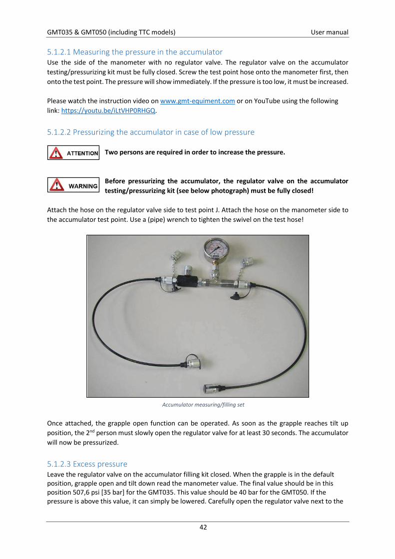
5.1.2 Pressurizing the accumulator The accumulator ensures that the saw blade retracts into the saw casing and that the tilt frame subsequently drops – under control – into the tilt down position. If the saw blade does not fully retract into the saw casing in tilt down position (default grapple position), the pressure in the accumulator may be too low. This pressure should be 35-40 bar. If the saw blade does not fully retract into the saw casing in tilt up position (horizontal grapple position), the pressure in the accumulator may be too high.
Measuring the pressure in the accumulator GMT035 (TTC) – required 35 bar
Measuring the pressure in the accumulator GMT050 (TTC) – required 40 bar
In case of one of the aforementioned problems, the pressure in the accumulator must be checked. This can be done using the supplied manometer kit.
GMT035 & GMT050 (including TTC models) User manual
42
5.1.2.1 Measuring the pressure in the accumulator Use the side of the manometer with no regulator valve. The regulator valve on the accumulator testing/pressurizing kit must be fully closed. Screw the test point hose onto the manometer first, then onto the test point. The pressure will show immediately. If the pressure is too low, it must be increased. Please watch the instruction video on www.gmt-equiment.com or on YouTube using the following link: https://youtu.be/iLtVHP0RHGQ.
5.1.2.2 Pressurizing the accumulator in case of low pressure Two persons are required in order to increase the pressure.
Before pressurizing the accumulator, the regulator valve on the accumulator testing/pressurizing kit (see below photograph) must be fully closed!
Attach the hose on the regulator valve side to test point J. Attach the hose on the manometer side to the accumulator test point. Use a (pipe) wrench to tighten the swivel on the test hose!
Once attached, the grapple open function can be operated. As soon as the grapple reaches tilt up position, the 2nd person must slowly open the regulator valve for at least 30 seconds. The accumulator will now be pressurized.
5.1.2.3 Excess pressure Leave the regulator valve on the accumulator filling kit closed. When the grapple is in the default position, grapple open and tilt down read the manometer value. The final value should be in this position 507,6 psi [35 bar] for the GMT035. This value should be 40 bar for the GMT050. If the pressure is above this value, it can simply be lowered. Carefully open the regulator valve next to the
Accumulator measuring/filling set
GMT035 & GMT050 (including TTC models) User manual
43
manometer and wait until the pressure drops to the correct level. Close the regulator valve and detach the pressurizing kit.
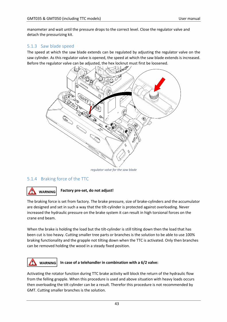
5.1.3 Saw blade speed The speed at which the saw blade extends can be regulated by adjusting the regulator valve on the saw cylinder. As this regulator valve is opened, the speed at which the saw blade extends is increased. Before the regulator valve can be adjusted, the hex locknut must first be loosened.
regulator valve for the saw blade
5.1.4 Braking force of the TTC Factory pre-set, do not adjust!
The braking force is set from factory. The brake pressure, size of brake-cylinders and the accumulator are designed and set in such a way that the tilt-cylinder is protected against overloading. Never increased the hydraulic pressure on the brake system it can result in high torsional forces on the crane end beam. When the brake is holding the load but the tilt-cylinder is still tilting down then the load that has been cut is too heavy. Cutting smaller tree parts or branches is the solution to be able to use 100% braking functionality and the grapple not tilting down when the TTC is activated. Only then branches can be removed holding the wood in a steady fixed position.
In case of a telehandler in combination with a 6/2 valve:
Activating the rotator function during TTC brake activity will block the return of the hydraulic flow from the felling grapple. When this procedure is used and above situation with heavy loads occurs then overloading the tilt cylinder can be a result. Therefor this procedure is not recommended by GMT. Cutting smaller branches is the solution.

GMT035 & GMT050 (including TTC models) User manual
44
6. How to decommission When the felling grapple is at the end of his lifetime, it should be disposed. Observe the following instructions so the environment won’t get contaminated unnecessarily. Take the felling grapple to an approved demolition company. The can carry out further removal of the grapple. When the grapple can’t be taken to an demolition company, then carry out the following;
Release the oil out of the hydraulic system and dispose it to the chemical waste. Remove all hydraulic hoses and take them to a designated collection point. Transfer the remained metal of the grapple to an metal recycling company. (TTC remote control) The battery is 98% recyclable. Return the old battery to a locally
recognized collection point.
GMT035 & GMT050 (including TTC models) User manual
45
7. Troubleshooting 7.1 General In manufacturing the GMT felling grapple, care has been taken to tailor the features of the chosen materials and components in such a way that they perform well in practice. This has been done to ensure the least possible number of malfunctions. In order to prevent hydraulic malfunctions, it is of crucial importance that the hydraulic system is kept clean. Cleanliness of the hydraulic fluid and timely replacement of hydraulic hoses will contribute to error-free performance. Use supporting information when trouble shooting is required or see our website: www.gmt-equipment.com
7.2 Checklist Become familiar with the system.
o Take note of service intervals and other instructions. Questions for the operator.
o What went wrong? o What functions may be affected? o Is this the right carrying vehicle? o Has maintenance been done correctly? o Have valve block settings been changed? o Have parts been replaced or removed?
Operate the machine and the felling grapple. o Try to trace possible errors/malfunctions. o Check whether the carrying vehicle actually meets the required specifications. o Operate at/work with different speeds in order to trace the potential problem.
Inspect the machine as a whole. o First check the hydraulic reservoir. o Then check the felling grapple. Start with the valve block, hoses for grapple open and
grapple close and the drain valve. o Check pressures by measuring them. o Check all three cylinders (for leaks around couplings or seals).
GMT035 & GMT050 (including TTC models) User manual
46
7.3 Common malfunctions 7.3.1 Sawing problems
Always make another attempt at sawing after fitting a new saw blade and chain first. If this does not solve the problem, please refer to the following potential causes and solutions:
Saw blade does not extend or barely extends from the saw casing:
Is the piston rod bent? Is the blue regulator valve used for saw blade and chain exchange still closed?
Saw blade does not make enough contact with wood:
Check the pressure in the accumulator. See 5.1.2 Check regulator valve on saw cylinder.
Saw stutters: Cause: too much pressure on the tree/branch and/or a lack of liters/flow available to the saw motor.
Adjust or reset regulator valve on the saw cylinder or provide the saw motor with more liters/flow.
Saw blade does not retract:
Check pressure in the accumulator. Then check the drain line and the drain valve. Is the ball valve still closed?
Saw works well in tilt down position, but not in tilt up position:
Pressure in the accumulator on the side of the tilt frame is too high use the accumulator test kit to release the pressure.
Saw blade sticks and does not cut straight:
Chain incorrectly sharpened, left and right chain links uneven. The saw blade is not flush with the saw bracket turn the long saw bolt further into the saw
bracket by adding one rotation. The saw blade has been bended replace saw blade for a new straight one.
7.3.2 Problems with tilt up, placing grapple in horizontal position Readjust valve 10. Unscrew and clean regulator beyond plug ‘N’.
7.3.3 Problems with tilt down, placing grapple in default position Check drain line and drain valve. Is the ball valve still closed? Check regulator 7. Unscrew and clean. Readjust valve 6. Place grapple in tilt up position, turn off the carrying vehicle and uncouple hose connected to
G.O. (grapple open) nipple on rotator. Does any fluid leak out? Problem with drain line or carrying vehicle.
GMT035 & GMT050 (including TTC models) User manual
47
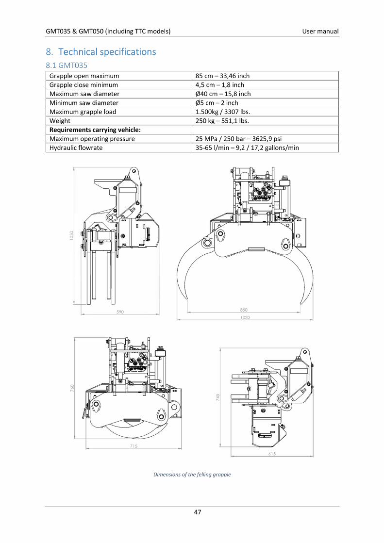
8. Technical specifications 8.1 GMT035
Grapple open maximum 85 cm – 33,46 inch Grapple close minimum 4,5 cm – 1,8 inch Maximum saw diameter Ø40 cm – 15,8 inch Minimum saw diameter Ø5 cm – 2 inch Maximum grapple load 1.500kg / 3307 lbs. Weight 250 kg – 551,1 lbs. Requirements carrying vehicle: Maximum operating pressure 25 MPa / 250 bar – 3625,9 psi Hydraulic flowrate 35-65 l/min – 9,2 / 17,2 gallons/min
Dimensions of the felling grapple
GMT035 & GMT050 (including TTC models) User manual
48
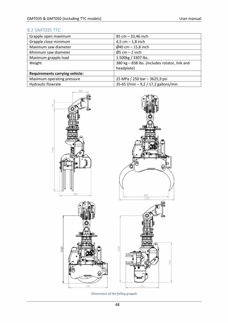
8.2 GMT035 TTC Grapple open maximum 85 cm – 33,46 inch Grapple close minimum 4,5 cm – 1,8 inch Maximum saw diameter Ø40 cm – 15,8 inch Minimum saw diameter Ø5 cm – 2 inch Maximum grapple load 1.500kg / 3307 lbs. Weight 380 kg – 838 lbs. (includes rotator, link and
headplate) Requirements carrying vehicle: Maximum operating pressure 25 MPa / 250 bar – 3625,9 psi Hydraulic flowrate 35-65 l/min – 9,2 / 17,2 gallons/min
Dimensions of the felling grapple
GMT035 & GMT050 (including TTC models) User manual
49
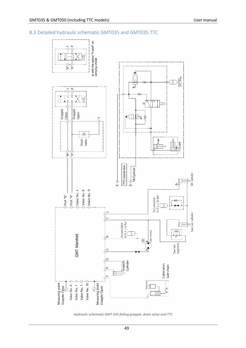
8.3 Detailed hydraulic schematic GMT035 and GMT035 TTC
Hydraulic schematic GMT 035 felling grapple, drain valve and TTC
GMT035 & GMT050 (including TTC models) User manual
50
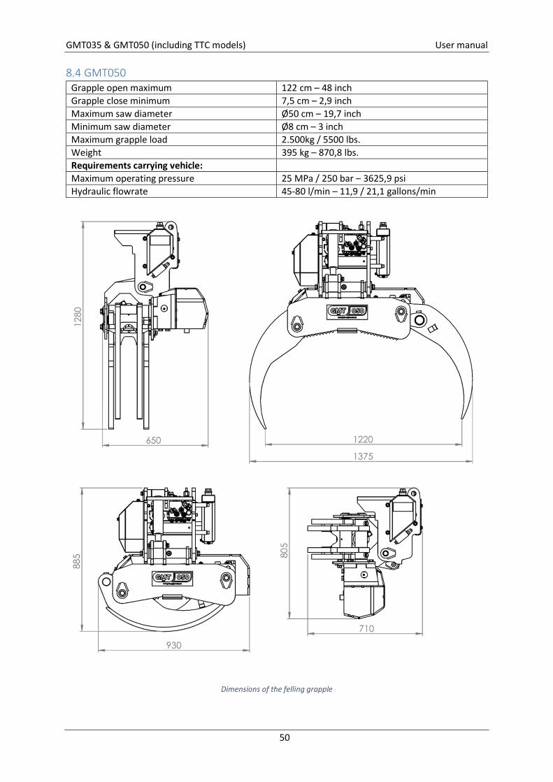
8.4 GMT050 Grapple open maximum 122 cm – 48 inch Grapple close minimum 7,5 cm – 2,9 inch Maximum saw diameter Ø50 cm – 19,7 inch Minimum saw diameter Ø8 cm – 3 inch Maximum grapple load 2.500kg / 5500 lbs. Weight 395 kg – 870,8 lbs. Requirements carrying vehicle: Maximum operating pressure 25 MPa / 250 bar – 3625,9 psi Hydraulic flowrate 45-80 l/min – 11,9 / 21,1 gallons/min
Dimensions of the felling grapple
GMT035 & GMT050 (including TTC models) User manual
51
Dimensions of the grapple saw
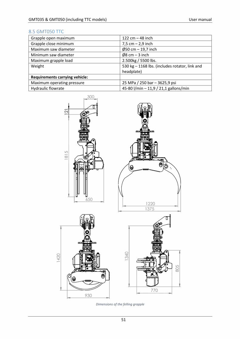
8.5 GMT050 TTC Grapple open maximum 122 cm – 48 inch Grapple close minimum 7,5 cm – 2,9 inch Maximum saw diameter Ø50 cm – 19,7 inch Minimum saw diameter Ø8 cm – 3 inch Maximum grapple load 2.500kg / 5500 lbs. Weight 530 kg – 1168 lbs. (includes rotator, link and
headplate) Requirements carrying vehicle: Maximum operating pressure 25 MPa / 250 bar – 3625,9 psi Hydraulic flowrate 45-80 l/min – 11,9 / 21,1 gallons/min
Dimensions of the felling grapple
GMT035 & GMT050 (including TTC models) User manual
52
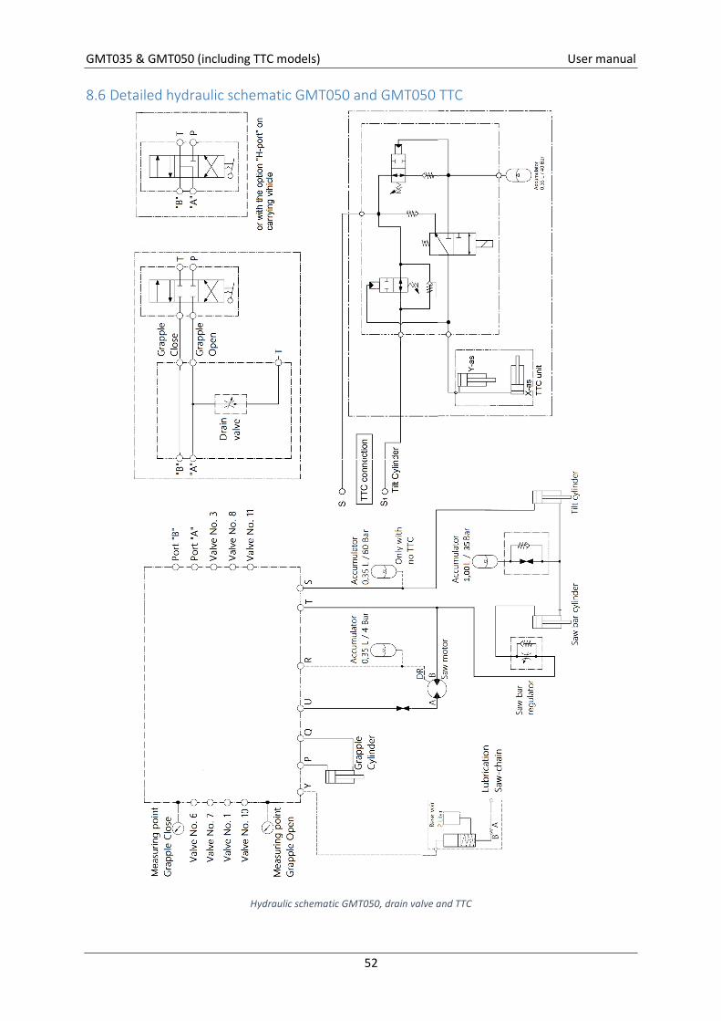
8.6 Detailed hydraulic schematic GMT050 and GMT050 TTC
Hydraulic schematic GMT050, drain valve and TTC
Related Documents