www.essilor-instruments.com User Manual

Welcome message from author
This document is posted to help you gain knowledge. Please leave a comment to let me know what you think about it! Share it to your friends and learn new things together.
Transcript
CONTENTS
I. INTRODUCTION 5
1. Outline of product 6
2. Classifications 6
II. SAFETY INFORMATION 7
1. Introduction 8
2. Indications for use 8
3. Safety symbols 9
4. Environmental factors 10
5. Safety precautions 12
III. FEATURES 13
IV. NOTES FOR USING THE INSTRUMENT 15
V. CONFIGURATION 17
VI. INSTALLATION 21
1. Instruction for wall mounting 22
2. Viewing distance (LCD display position) 22
3. Feature set 23a. Feature set mode menu 23
b. Feature set mode setting method 23
c. Feature set mode disable 24
d. Function set overview 24
VII. TEST METHOD 31
VIII. REMOTE CONTROL FUNCTION 37
1. General function 38
2. Slide function 39
IX. HOW TO RECHARGE A REMOTE CONTROL 41
X. CLEANING THE PRODUCT 43
XI. TROUBLESHOOTING GUIDE 45
XII. ENVIRONMENTAL CONDITIONS 47
XIII. SPECIFICATIONS 49
XIV. COMPONENTS LIST 51
1. Standard accessories 52
2. Optional accessories 52
XV. SERVICE INFORMATION 53
1. Repair 54
USER MANUAL> CONTENTS
I. INTRODUCTION
1. OUTLINE OF PRODUCT
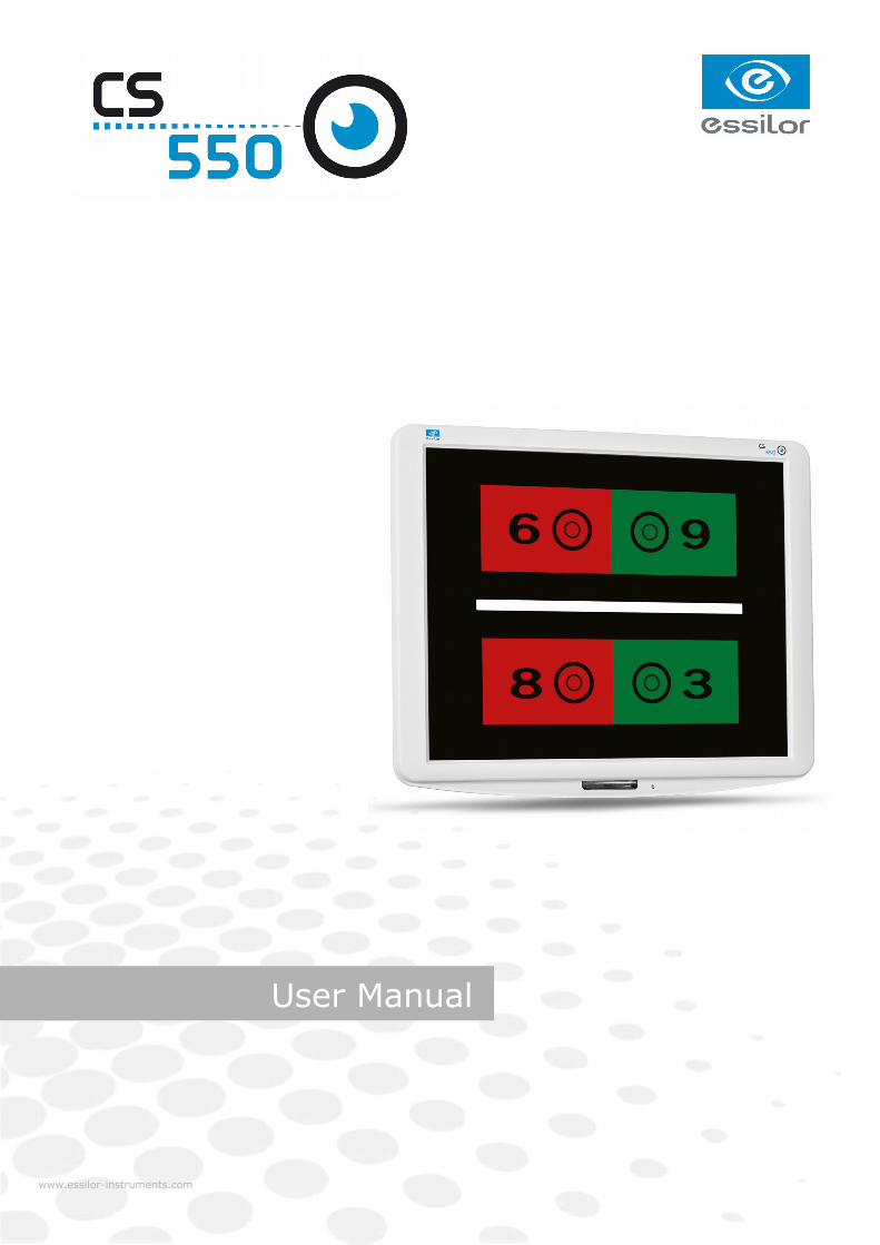
CS550 is an automatic visual acuity system, stand-alone type, which displays broad range of charts, basedon LCD panel, including red /green for the eye optometry.
The chart rotation for CS550 can be performed by either wired or wireless remote control or by externaldevices by control box of Digital Phoropter.
Unlike existing chart projector, CS550 is able to provide wider range of charts (more than 100 kinds ofgeneral and special charts) on LCD panel and the product can be adjusted at the level of the patients forprecise examination.
2. CLASSIFICATIONS
• Classification of equipment: Class I
• Applied part of equipment: no applied part
• Protection against electric shock: Class I
• Protection against harmful ingress of water: ordinary (IPX0)
• Method of sterilization: not applicable
• Stability of use in an oxygen rich environment: not suitable
• Mode of operation: continuous operation
CS550 - Chart system > V1 - 10-20156
USER MANUAL> I. INTRODUCTION

II. SAFETY INFORMATION
1. INTRODUCTION
Safety is everyone's responsibility. The safe use of this equipment is largely dependent upon the installer,user, operator, and maintainer. It is imperative that personnel study and become familiar with this entiremanual before attempting to install, use, clean, service or adjust this equipment and any associatedaccessories. It is paramount that the instructions contained in this manual are fully understood and followedto enhance safety to the patient and the user/operator. It is for this reason that the following safety noticeshave been placed appropriately within the text of this manual to highlight safety related information orinformation requiring special emphasis. All users, operators, and maintainers must be familiar with and payparticular attention to all Warnings and Cautions incorporated herein.
Accessory equipment connected to the analog and digital interfaces must be certificated according to therespective IEC standards (e.g. IEC 60950-1 for data processing equipment and IEC 60601-1 for medicalequipment). Furthermore all configurations shall comply with the system standard EN 60601-1:2006, Clause16. Everybody who connects additional equipment to the signal input part or signal output part configures amedical system, and is therefore responsible that the system complies with the requirements of the systemstandard IEC 60601-1:2005, Clause 16. If in doubt, consult the technical service department or your localrepresentative.
“Warning” indicates the presence of a hazard that could result in severe personal injury, death orsubstantial property damage if ignored.
“Note” describes information for the installation, operation, or maintenance of which is important buthazard related if ignored.
“Caution” indicates the presence of a hazard that could result in minor injury, or property damaged ifignored.
This device is compliant with marking.
Date of first marking: October 2015.
2. INDICATIONS FOR USE
The indications for use include the visual acuity for determining patient objective refraction.
CS550 - Chart system > V1 - 10-20158
USER MANUAL> II. SAFETY INFORMATION
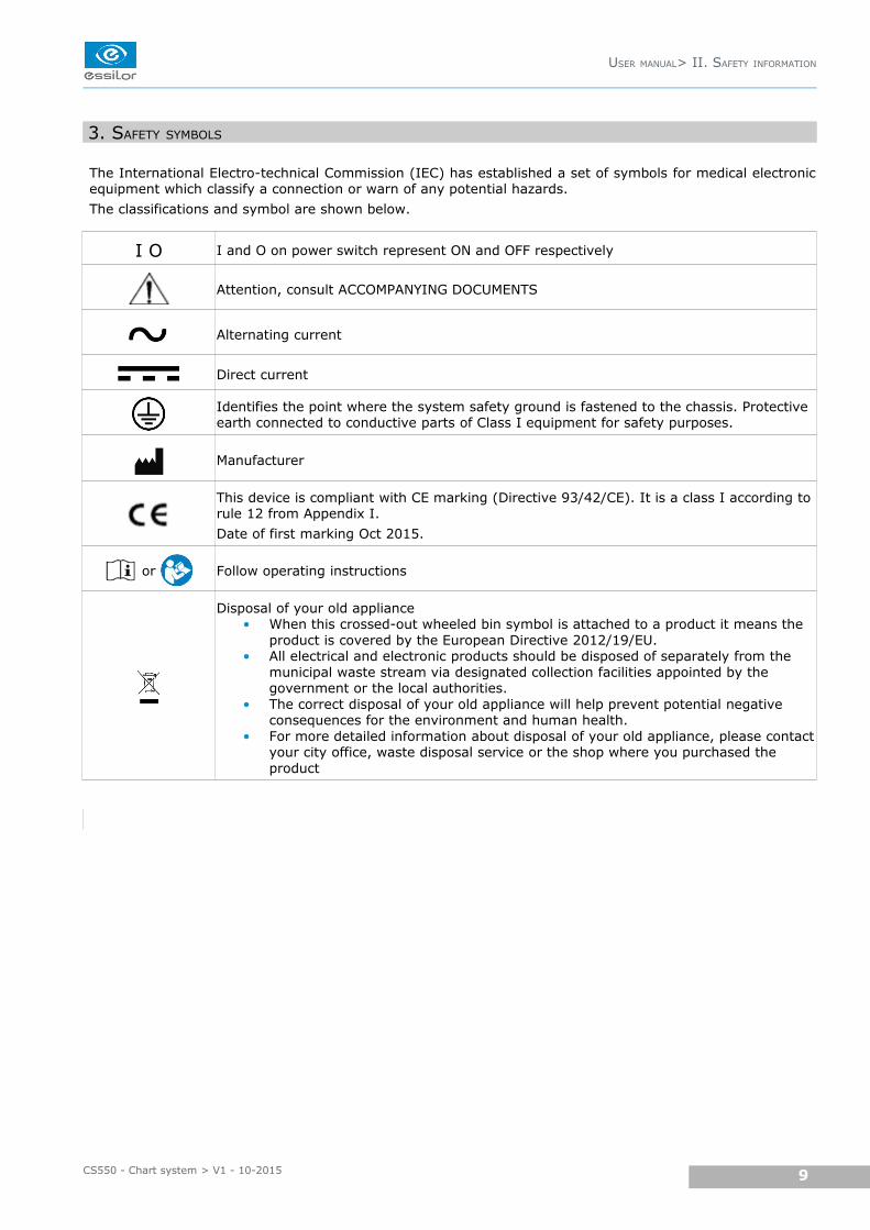
3. SAFETY SYMBOLS
The International Electro-technical Commission (IEC) has established a set of symbols for medical electronicequipment which classify a connection or warn of any potential hazards.
The classifications and symbol are shown below.
I O I and O on power switch represent ON and OFF respectively
Attention, consult ACCOMPANYING DOCUMENTS
Alternating current
Direct current
Identifies the point where the system safety ground is fastened to the chassis. Protective earth connected to conductive parts of Class I equipment for safety purposes.
Manufacturer
This device is compliant with CE marking (Directive 93/42/CE). It is a class I according torule 12 from Appendix I.
Date of first marking Oct 2015.
or Follow operating instructions
Disposal of your old appliance• When this crossed-out wheeled bin symbol is attached to a product it means the
product is covered by the European Directive 2012/19/EU. • All electrical and electronic products should be disposed of separately from the
municipal waste stream via designated collection facilities appointed by the government or the local authorities.
• The correct disposal of your old appliance will help prevent potential negative consequences for the environment and human health.
• For more detailed information about disposal of your old appliance, please contactyour city office, waste disposal service or the shop where you purchased the product
USER MANUAL> II. SAFETY INFORMATION
9CS550 - Chart system > V1 - 10-2015
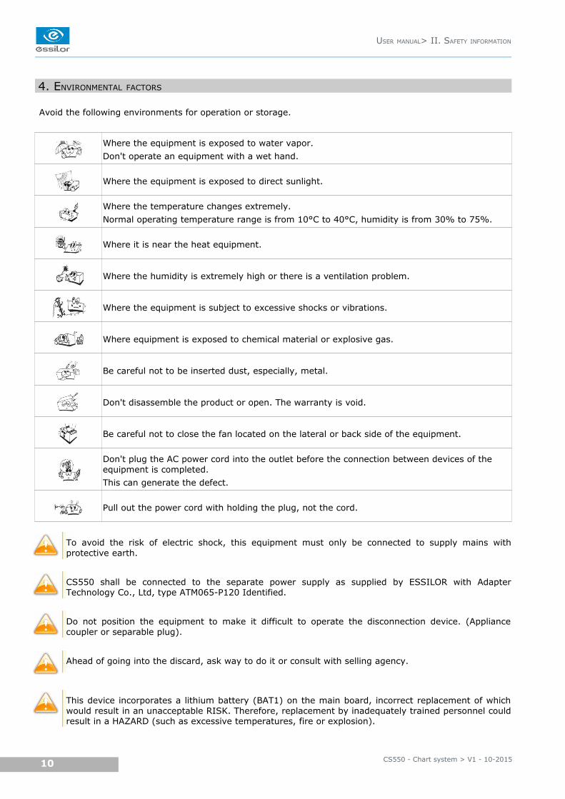
4. ENVIRONMENTAL FACTORS
Avoid the following environments for operation or storage.
Where the equipment is exposed to water vapor.
Don't operate an equipment with a wet hand.
Where the equipment is exposed to direct sunlight.
Where the temperature changes extremely.
Normal operating temperature range is from 10°C to 40°C, humidity is from 30% to 75%.
Where it is near the heat equipment.
Where the humidity is extremely high or there is a ventilation problem.
Where the equipment is subject to excessive shocks or vibrations.
Where equipment is exposed to chemical material or explosive gas.
Be careful not to be inserted dust, especially, metal.
Don't disassemble the product or open. The warranty is void.
Be careful not to close the fan located on the lateral or back side of the equipment.
Don't plug the AC power cord into the outlet before the connection between devices of the equipment is completed.
This can generate the defect.
Pull out the power cord with holding the plug, not the cord.
To avoid the risk of electric shock, this equipment must only be connected to supply mains withprotective earth.
CS550 shall be connected to the separate power supply as supplied by ESSILOR with AdapterTechnology Co., Ltd, type ATM065-P120 Identified.
Do not position the equipment to make it difficult to operate the disconnection device. (Appliancecoupler or separable plug).
Ahead of going into the discard, ask way to do it or consult with selling agency.
This device incorporates a lithium battery (BAT1) on the main board, incorrect replacement of whichwould result in an unacceptable RISK. Therefore, replacement by inadequately trained personnel couldresult in a HAZARD (such as excessive temperatures, fire or explosion).
CS550 - Chart system > V1 - 10-201510
USER MANUAL> II. SAFETY INFORMATION
Do not placed the multiple socket-outlet for CS550 system on the floor in order to prevent liquidpenetration and damage to the product.
CS550 system shall not be connected with additional multiple socket-outlets or extension cords inaddition to a designated single multiple socket-outlet.
Maximum permissible load of each socket-outlet used for the CS550 system, shall not be less than60VA.
Do not connect the device which is not a supplement of CS550 with the multiple socket-outlet ofCS550.
Multiple socket-outlet should be a grounding-type and complied with IEC 60884-1.
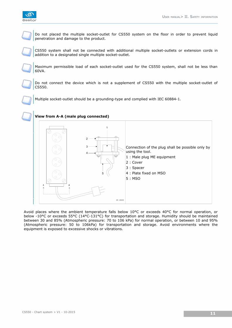
View from A-A (male plug connected)
Connection of the plug shall be possible only by using the tool.
1 : Male plug ME equipment
2 : Cover
3 : Spacer
4 : Plate fixed on MSO
5 : MSO
Avoid places where the ambient temperature falls below 10°C or exceeds 40°C for normal operation, orbelow -10°C or exceeds 55°C (14°C-131°C) for transportation and storage. Humidity should be maintainedbetween 30 and 85% (Atmospheric pressure: 70 to 106 kPa) for normal operation, or between 10 and 95%(Atmospheric pressure: 50 to 106kPa) for transportation and storage. Avoid environments where theequipment is exposed to excessive shocks or vibrations.
USER MANUAL> II. SAFETY INFORMATION
11CS550 - Chart system > V1 - 10-2015
5. SAFETY PRECAUTIONS
This equipment has been developed and tested according to safety standards as well as national andinternational standards. This guarantees a very high degree of safety for this device. The legislator expectsus to inform the user expressively about the safety aspects in dealing with the device. The correct handlingof this equipment is imperative for its safe operation. Therefore, please read carefully all instructions beforeswitching on this device. For more detailed information, please contact our Customer Service Department orone of our authorized representatives.
1. This equipment must not be used (a) in an area that is in danger of explosions and (b) in the
presence of flammable, explosive, or volatile solvent such as alcohol, benzene or similar chemicals.
2. Do not put or use this device in humid rooms. Humidity should be maintained between 30 and 75%
for normal operation. Do not expose the device to water splashes, dripping water, or sprayed water.
Do not place containers containing fluids, liquids, or gases on top of any electrical equipment or
devices.
3. The equipment must be operated only by, or under direct supervision of a properly trained and
qualified person.
4. Modifications of this equipment may only be carried out by trained service technicians or other
authorized persons.
5. Customer maintenance of this equipment may only be performed as stated in the user's manual and
service manual. Any additional maintenance may only be performed by trained service technicians or
other authorized persons.
6. The manufacturer is only responsible for effects on safety, reliability, and performance of this
equipment when the following requirements are fulfilled: (1) The electrical installation in the
respective room corresponds to the specifications stated in this manual and (2) This equipment is
used, operated, and maintained according to this manual and service manual.
7. The manufacturer is not liable for damage caused by unauthorized tampering with the device(s). Such
tampering will forfeit any rights to claim under warranty.
8. Interconnected equipment to this equipment shall be complied with the applicable international
standards, e.g. IEC/EN 60950-1 for I.T equipment.
9. Only persons who have undergone proper training and instructions are authorized to install, use,
operate, and maintain this equipment.
10.Keep the user's manual and service manual in a place easily accessible at all times for persons
operating and maintaining the equipment.
11.Do not force cable connections. If a cable does not connect easily, be sure that the connector (plug) is
appropriate for the receptacle (socket). If you cause any damage to a cable connector(s) or
receptacle(s), let the damage(s) be repaired by an authorized service technician.
12.Please do not pull on any cable. Always hold on to the plug when disconnecting cables.
13.This equipment may be used for the international application related to (*Usages of Device) according
to this manual.
14.Before each operation, visually check the equipment for exterior mechanical damage(s) and for
proper function.
15.Do not cover any ventilation grids or slits.
16.Immediately turn off and unplug any equipment that gives off smoke, sparks, strange noises or
odors.
CS550 - Chart system > V1 - 10-201512
USER MANUAL> II. SAFETY INFORMATION

III. FEATURES
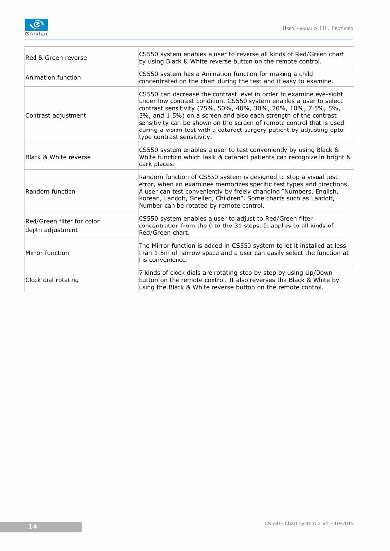
Red & Green reverse CS550 system enables a user to reverse all kinds of Red/Green chart by using Black & White reverse button on the remote control.
Animation function CS550 system has a Animation function for making a child concentrated on the chart during the test and it easy to examine.
Contrast adjustment
CS550 can decrease the contrast level in order to examine eye-sight under low contrast condition. CS550 system enables a user to select contrast sensitivity (75%, 50%, 40%, 30%, 20%, 10%, 7.5%, 5%, 3%, and 1.5%) on a screen and also each strength of the contrast sensitivity can be shown on the screen of remote control that is used during a vision test with a cataract surgery patient by adjusting opto-type contrast sensitivity.
Black & White reverseCS550 system enables a user to test conveniently by using Black & White function which lasik & cataract patients can recognize in bright & dark places.
Random function
Random function of CS550 system is designed to stop a visual test error, when an examinee memorizes specific test types and directions. A user can test conveniently by freely changing “Numbers, English, Korean, Landolt, Snellen, Children”. Some charts such as Landolt, Number can be rotated by remote control.
Red/Green filter for color
depth adjustment
CS550 system enables a user to adjust to Red/Green filter concentration from the 0 to the 31 steps. It applies to all kinds of Red/Green chart.
Mirror functionThe Mirror function is added in CS550 system to let it installed at less than 1.5m of narrow space and a user can easily select the function at his convenience.
Clock dial rotating7 kinds of clock dials are rotating step by step by using Up/Down button on the remote control. It also reverses the Black & White by using the Black & White reverse button on the remote control.
CS550 - Chart system > V1 - 10-201514
USER MANUAL> III. FEATURES
IV. NOTES FOR USING THE INSTRUMENT
1. Do not hit or drop the instrument. The instrument may be damaged if it receives a strong impact. The
impact can damage the function of this product. Handle it with care.
2. Keep this product from vibration.
3. Exposure of direct sunlight or very bright indoor lights can affect the result of measurements.
4. Don't use organic solution such as alcohol, thinner, benzene, etc. to clean the surface of this
instrument. It may damage the product.
5. Disconnect the power supply and consult the dealer when there is smoke, strange odors, or noise
while working.
CS550 - Chart system > V1 - 10-201516
USER MANUAL> IV. NOTES FOR USING THE INSTRUMENT
V. CONFIGURATION
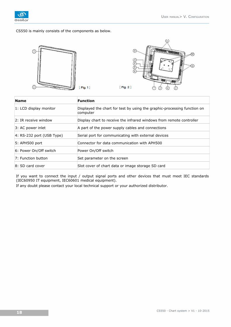
CS550 is mainly consists of the components as below.
Name Function
1: LCD display monitor Displayed the chart for test by using the graphic-processing function on computer
2: IR receive window Display chart to receive the infrared windows from remote controller
3: AC power inlet A part of the power supply cables and connections
4: RS-232 port (USB Type) Serial port for communicating with external devices
5: APH500 port Connector for data communication with APH500
6: Power On/Off switch Power On/Off switch
7: Function button Set parameter on the screen
8: SD card cover Slot cover of chart data or image storage SD card
If you want to connect the input / output signal ports and other devices that must meet IEC standards(IEC60950 IT equipment, IEC60601 medical equipment).
If any doubt please contact your local technical support or your authorized distributor.
CS550 - Chart system > V1 - 10-201518
USER MANUAL> V. CONFIGURATION
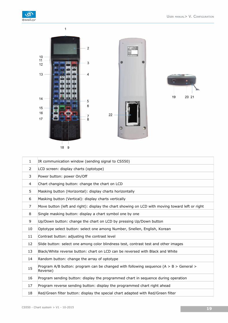
1 IR communication window (sending signal to CS550)
2 LCD screen: display charts (optotype)
3 Power button: power On/Off
4 Chart changing button: change the chart on LCD
5 Masking button (Horizontal): display charts horizontally
6 Masking button (Vertical): display charts vertically
7 Move button (left and right): display the chart showing on LCD with moving toward left or right
8 Single masking button: display a chart symbol one by one
9 Up/Down button: change the chart on LCD by pressing Up/Down button
10 Optotype select button: select one among Number, Snellen, English, Korean
11 Contrast button: adjusting the contrast level
12 Slide button: select one among color blindness test, contrast test and other images
13 Black/White reverse button: chart on LCD can be reversed with Black and White
14 Random button: change the array of optotype
15Program A/B button: program can be changed with following sequence (A > B > General > Reverse)
16 Program sending button: display the programmed chart in sequence during operation
17 Program reverse sending button: display the programmed chart right ahead
18 Red/Green filter button: display the special chart adapted with Red/Green filter
USER MANUAL> V. CONFIGURATION
19CS550 - Chart system > V1 - 10-2015
19 Mini USB socket: for operating CS550 and for charging the remote control battery
20 LED: indicating the status of electric charge
21 Loop part: connect the string with this part
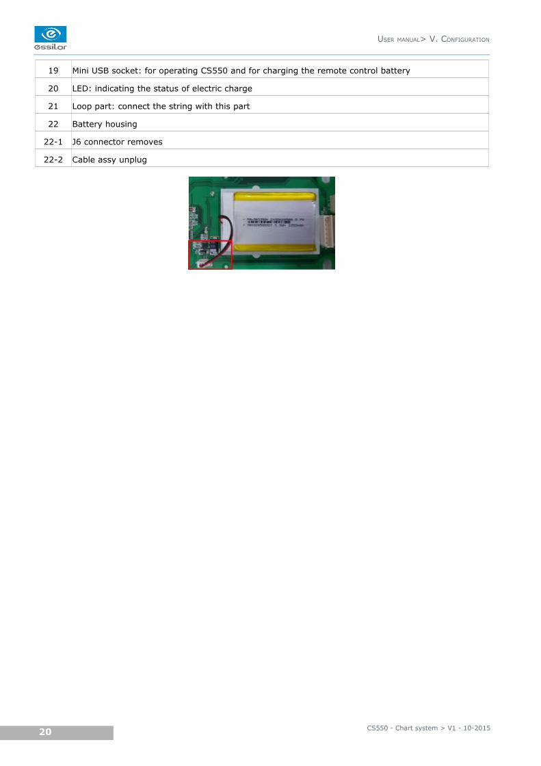
22 Battery housing
22-1 J6 connector removes
22-2 Cable assy unplug
CS550 - Chart system > V1 - 10-201520
USER MANUAL> V. CONFIGURATION
VI. INSTALLATION
1. INSTRUCTION FOR WALL MOUNTING
Unsecured product could be dislodgeg and fall which causes injury to either patient or examiner.
All cables related to the product shall be handled with care for preventing the examiner or the patientfrom any kinds of dangers.
Be sure that the position you choose to mount the product shall be within the reach of a power outlet.
• Find an appropriate point on the wall which will support the product, which will hang from the wall-
mount bracket attached to the wall.
• Make sure that the refraction distance meets the requirements for either direct-view or mirror
arrangement.
• Level the supplied wall mount bracket with the metal tabs facing up and out on your wall and mark
the holes on the installation.
• Place the wall mount bracket on the wall, and screw or tap the screws (nail) into the holes. Hang the
product by lining up the holes on the back of unit with the metal tabs of the wall mount bracket and
hang the unit on these tabs.
Do not overdrive the inserts into the wall.
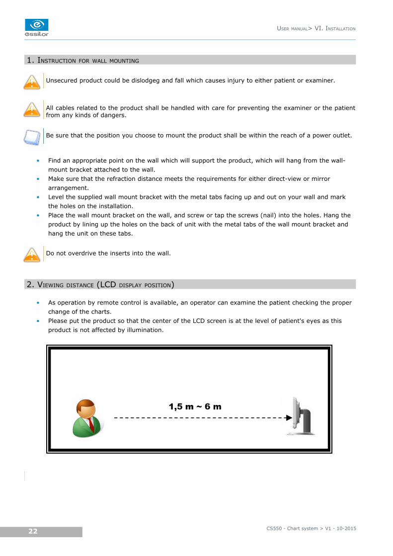
2. VIEWING DISTANCE (LCD DISPLAY POSITION)
• As operation by remote control is available, an operator can examine the patient checking the proper
change of the charts.
• Please put the product so that the center of the LCD screen is at the level of patient's eyes as this
product is not affected by illumination.
CS550 - Chart system > V1 - 10-201522
USER MANUAL> VI. INSTALLATION
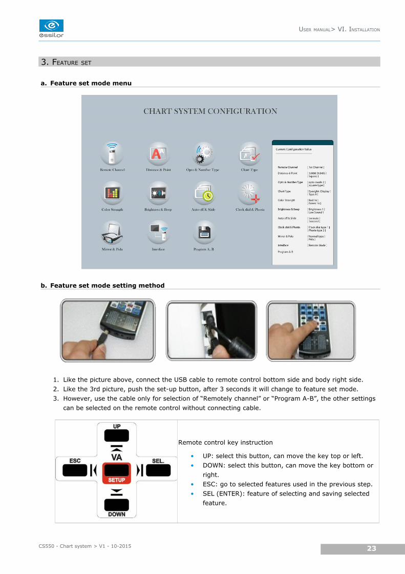
3. FEATURE SET
a. Feature set mode menu
b. Feature set mode setting method
1. Like the picture above, connect the USB cable to remote control bottom side and body right side.
2. Like the 3rd picture, push the set-up button, after 3 seconds it will change to feature set mode.
3. However, use the cable only for selection of “Remotely channel” or “Program A-B”, the other settings
can be selected on the remote control without connecting cable.
Remote control key instruction
• UP: select this button, can move the key top or left.
• DOWN: select this button, can move the key bottom or
right.
• ESC: go to selected features used in the previous step.
• SEL (ENTER): feature of selecting and saving selected
feature.
USER MANUAL> VI. INSTALLATION
23CS550 - Chart system > V1 - 10-2015
c. Feature set mode disable
1. Select the feature
2. Push the SEL (ENTER) key and ESC key
3. It will show the initial mode
4. Push the ESC key again and the following screen will show configuration is changed
Do you want to change the configuration? Enter: YES, Cancel: NO
• Yes (SEL key): If this key is selected, it saves set-point with system booting and even changes
initialized.
• No (ESC key): Users can select this key to return to “feature select” initialized mode.
If operator doesn't choose the new set-point in the feature selecting mode but doesn't show the abovemessage, push the ESC key again to go back to initial mode.
If operator has completed the feature setting by remote control like above, operator has to press the powerkey (off then on).
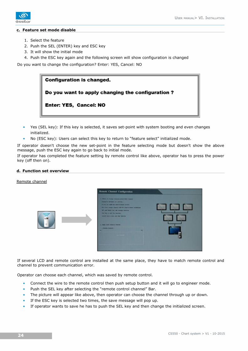
d. Function set overview
Remote channel
If several LCD and remote control are installed at the same place, they have to match remote control andchannel to prevent communication error.
Operator can choose each channel, which was saved by remote control.
• Connect the wire to the remote control then push setup button and it will go to engineer mode.
• Push the SEL key after selecting the “remote control channel” Bar.
• The picture will appear like above, then operator can choose the channel through up or down.
• If the ESC key is selected two times, the save message will pop up.
• If operator wants to save he has to push the SEL key and then change the initialized screen.
CS550 - Chart system > V1 - 10-201524
USER MANUAL> VI. INSTALLATION
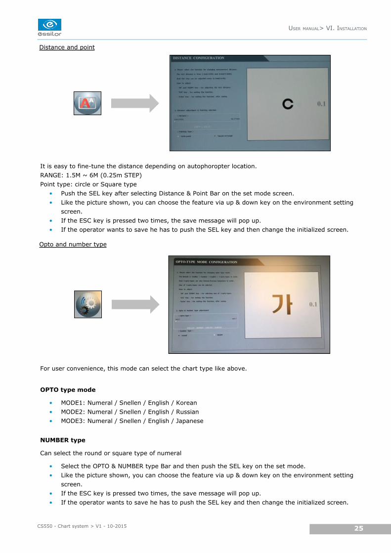
Distance and point
It is easy to fine-tune the distance depending on autophoropter location.
RANGE: 1.5M ~ 6M (0.25m STEP)
Point type: circle or Square type
• Push the SEL key after selecting Distance & Point Bar on the set mode screen.
• Like the picture shown, you can choose the feature via up & down key on the environment setting
screen.
• If the ESC key is pressed two times, the save message will pop up.
• If the operator wants to save he has to push the SEL key and then change the initialized screen.
Opto and number type
For user convenience, this mode can select the chart type like above.
OPTO type mode
• MODE1: Numeral / Snellen / English / Korean
• MODE2: Numeral / Snellen / English / Russian
• MODE3: Numeral / Snellen / English / Japanese
NUMBER type
Can select the round or square type of numeral
• Select the OPTO & NUMBER type Bar and then push the SEL key on the set mode.
• Like the picture shown, you can choose the feature via up & down key on the environment setting
screen.
• If the ESC key is pressed two times, the save message will pop up.
• If the operator wants to save he has to push the SEL key and then change the initialized screen.
USER MANUAL> VI. INSTALLATION
25CS550 - Chart system > V1 - 10-2015
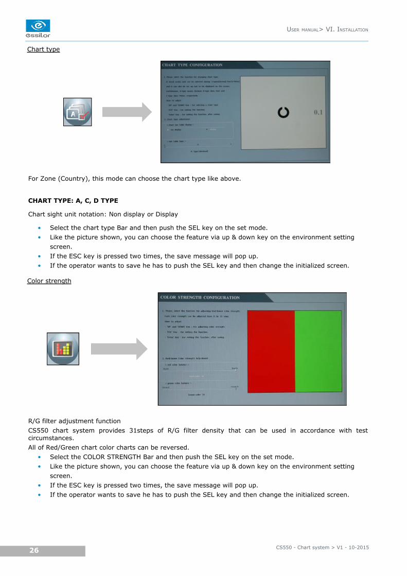
Chart type
For Zone (Country), this mode can choose the chart type like above.
CHART TYPE: A, C, D TYPE
Chart sight unit notation: Non display or Display
• Select the chart type Bar and then push the SEL key on the set mode.
• Like the picture shown, you can choose the feature via up & down key on the environment setting
screen.
• If the ESC key is pressed two times, the save message will pop up.
• If the operator wants to save he has to push the SEL key and then change the initialized screen.
Color strength
R/G filter adjustment function
CS550 chart system provides 31steps of R/G filter density that can be used in accordance with testcircumstances.
All of Red/Green chart color charts can be reversed.
• Select the COLOR STRENGTH Bar and then push the SEL key on the set mode.
• Like the picture shown, you can choose the feature via up & down key on the environment setting
screen.
• If the ESC key is pressed two times, the save message will pop up.
• If the operator wants to save he has to push the SEL key and then change the initialized screen.
CS550 - Chart system > V1 - 10-201526
USER MANUAL> VI. INSTALLATION
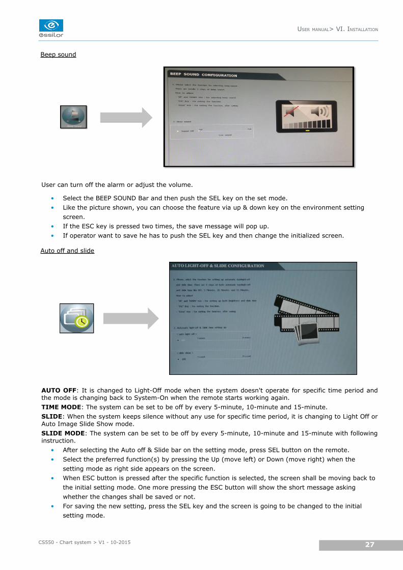
Beep sound
User can turn off the alarm or adjust the volume.
• Select the BEEP SOUND Bar and then push the SEL key on the set mode.
• Like the picture shown, you can choose the feature via up & down key on the environment setting
screen.
• If the ESC key is pressed two times, the save message will pop up.
• If operator want to save he has to push the SEL key and then change the initialized screen.
Auto off and slide
AUTO OFF: It is changed to Light-Off mode when the system doesn't operate for specific time period andthe mode is changing back to System-On when the remote starts working again.
TIME MODE: The system can be set to be off by every 5-minute, 10-minute and 15-minute.
SLIDE: When the system keeps silence without any use for specific time period, it is changing to Light Off orAuto Image Slide Show mode.
SLIDE MODE: The system can be set to be off by every 5-minute, 10-minute and 15-minute with followinginstruction.
• After selecting the Auto off & Slide bar on the setting mode, press SEL button on the remote.
• Select the preferred function(s) by pressing the Up (move left) or Down (move right) when the
setting mode as right side appears on the screen.
• When ESC button is pressed after the specific function is selected, the screen shall be moving back to
the initial setting mode. One more pressing the ESC button will show the short message asking
whether the changes shall be saved or not.
• For saving the new setting, press the SEL key and the screen is going to be changed to the initial
setting mode.
USER MANUAL> VI. INSTALLATION
27CS550 - Chart system > V1 - 10-2015
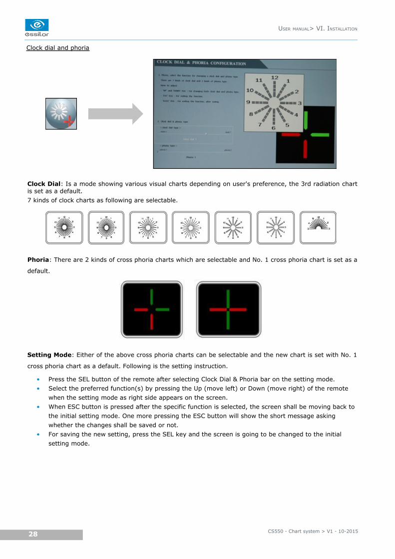
Clock dial and phoria
Clock Dial: Is a mode showing various visual charts depending on user's preference, the 3rd radiation chartis set as a default.
7 kinds of clock charts as following are selectable.
Phoria: There are 2 kinds of cross phoria charts which are selectable and No. 1 cross phoria chart is set as a
default.
Setting Mode: Either of the above cross phoria charts can be selectable and the new chart is set with No. 1
cross phoria chart as a default. Following is the setting instruction.
• Press the SEL button of the remote after selecting Clock Dial & Phoria bar on the setting mode.
• Select the preferred function(s) by pressing the Up (move left) or Down (move right) of the remote
when the setting mode as right side appears on the screen.
• When ESC button is pressed after the specific function is selected, the screen shall be moving back to
the initial setting mode. One more pressing the ESC button will show the short message asking
whether the changes shall be saved or not.
• For saving the new setting, press the SEL key and the screen is going to be changed to the initial
setting mode.
CS550 - Chart system > V1 - 10-201528
USER MANUAL> VI. INSTALLATION
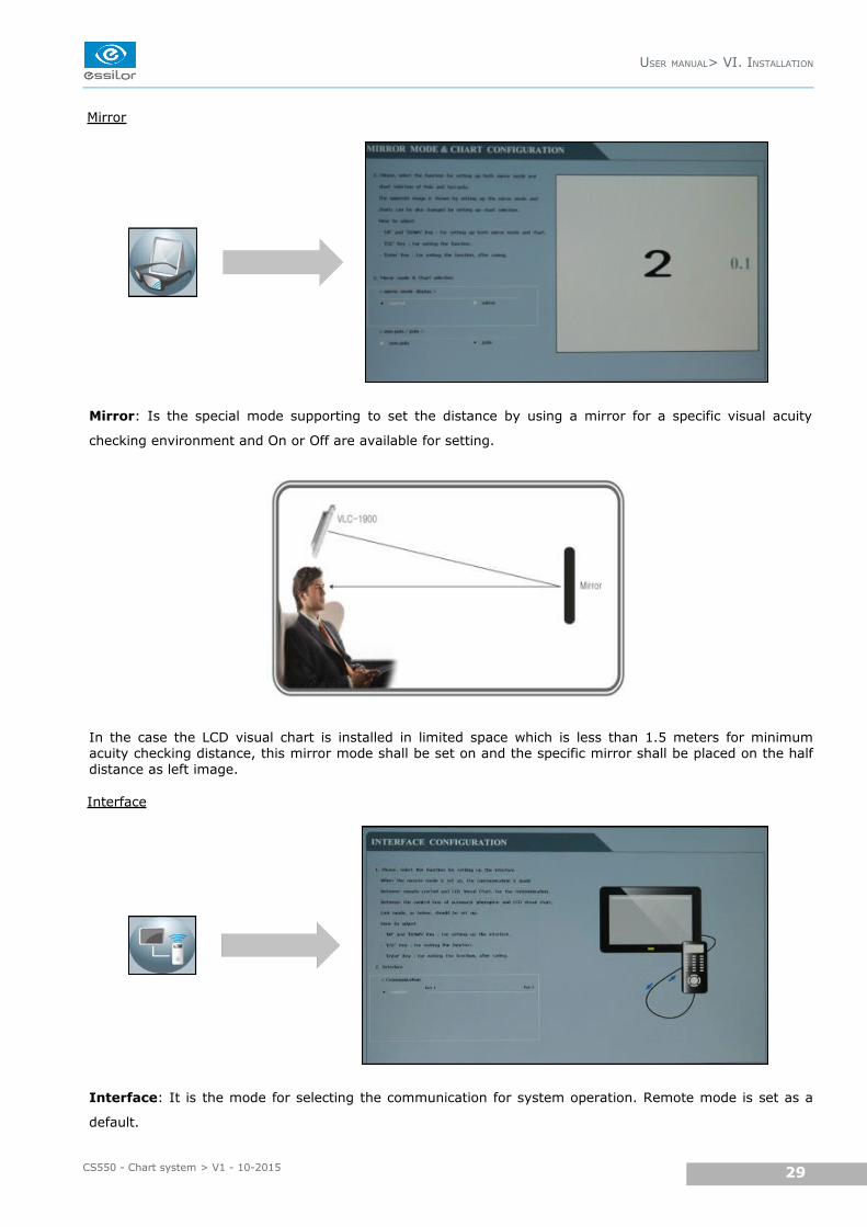
Mirror
Mirror: Is the special mode supporting to set the distance by using a mirror for a specific visual acuity
checking environment and On or Off are available for setting.
In the case the LCD visual chart is installed in limited space which is less than 1.5 meters for minimumacuity checking distance, this mirror mode shall be set on and the specific mirror shall be placed on the halfdistance as left image.
Interface
Interface: It is the mode for selecting the communication for system operation. Remote mode is set as a
default.
USER MANUAL> VI. INSTALLATION
29CS550 - Chart system > V1 - 10-2015
Program A/B
Program A-B: Program A or Program B can save the specific visual acuity charts which user prefers inadvance and show the visual charts in sequence by pressing the specific button.
Following is the instruction.
• Insert the wire cable connector to the remote and enter the engineering mode by pressing the ‘setup'
button of remote for a few seconds.
• Press SEL button of the remote after selecting the Program A-B bar.
• When the setting mode shown right appears, select the Program A by pressing SEL button.
• When Box cursor shows in Program A, press SEL button and press the button for specific visual acuity
chart shown on the remote, then the selected visual acuity chart appears in the box cursor. If other
visual acuity chart is preferred, it can be selected with the same procedure.
• All available visual acuity charts can be selected by moving the box cursor with Up (move left) or
Down (move right). Each Program can save maximum 8 charts.
• When the Program A saves full charts (max 8 charts), press the SEL button then the box cursor
moves to Program B.
When Program B can save maximum 8 visual acuity charts with the same procedure, press ESC
button which will lead to initial setting mode. One more pressing the ESC button will show the short
message asking whether the changes shall be saved or not.
For saving the new setting, press the SEL key and the screen is going to be changed to the initial
setting mode.
• When going back to the default screen for acuity chart, press Program A and press the arrow button
(=>l, l<=), then the visual acuity charts which are saved in Program A shows in sequence. It is the
same procedure for showing charts saved in Program B.
CS550 - Chart system > V1 - 10-201530
USER MANUAL> VI. INSTALLATION
VII. TEST METHOD
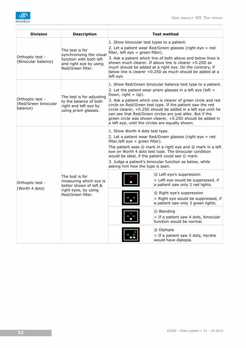
Division Description Test method
Orthoptic test - (Binocular balance)
The test is for synchronizing the visual function with both left and right eye by using Red/Green filter.
1. Show binocular test types to a patient.
2. Let a patient wear Red/Green glasses (right eye = red filter, left eye = green filter).
3. Ask a patient which line of both above and below lines is shown much clearer. If above line is clearer +0.25D as much should be added at a right eye. On the contrary, if below line is clearer +0.25D as much should be added at a left eye.
Orthoptic test - (Red/Green binocular balance)
The test is for adjusting to the balance of both right and left eye by using prism glasses.
1. Show Red/Green binocular balance test type to a patient.
2. Let the patient wear prism glasses in a left eye (left = Down, right = Up).
3. Ask a patient which one is clearer of green circle and red circle on Red/Green test type. If the patient saw the red circle clearer, +0.25D should be added in a left eye until he can see that Red/Green circles are just alike. But if the green circle was shown clearer, +0.25D should be added in a left eye, until the circles are equally shown.
Orthoptic test -
(Worth 4 dots)
The test is for measuring which eye is better shown of left & right eyes, by using Red/Green filter.
1. Show Worth 4 dots test type.
2. Let a patient wear Red/Green glasses (right eye = red filter,left eye = green filter).
The patient sees mark in a right eye and mark in a leftⓐ ⓑeye on Worth 4 dots test type. The binocular condition would be ideal, if the patient could see mark.ⓒ3. Judge a patient's binocular function as below, while asking him how the type is seen.
Left eye's suppressionⓐ> Left eye would be suppressed, if a patient saw only 2 red lights.
Right eye's suppressionⓑ> Right eye would be suppressed, ifa patient saw only 3 green lights.
Blendingⓒ> If a patient saw 4 dots, binocular function would be normal.
Diplopiaⓓ> If a patient saw 5 dots, he/she would have diplopia.
CS550 - Chart system > V1 - 10-201532
USER MANUAL> VII. TEST METHOD
Division Description Test method
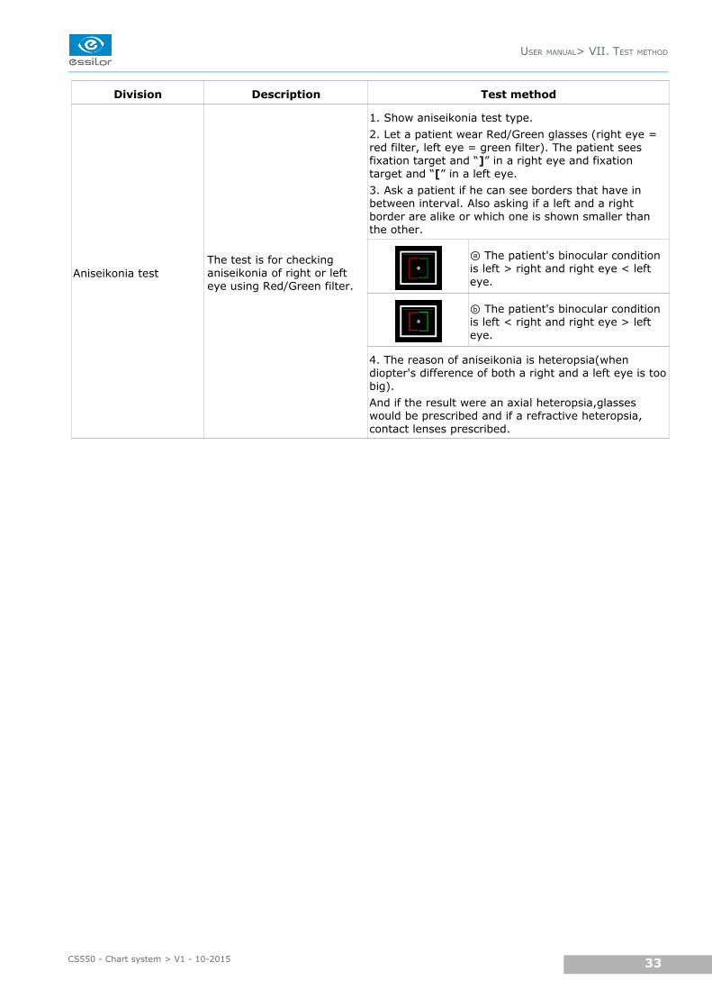
Aniseikonia testThe test is for checking aniseikonia of right or left eye using Red/Green filter.
1. Show aniseikonia test type.
2. Let a patient wear Red/Green glasses (right eye =red filter, left eye = green filter). The patient seesfixation target and “]” in a right eye and fixationtarget and “[” in a left eye.
3. Ask a patient if he can see borders that have inbetween interval. Also asking if a left and a rightborder are alike or which one is shown smaller thanthe other.
The patient's binocular condition ⓐis left > right and right eye < left eye.
The patient's binocular condition ⓑis left < right and right eye > left eye.
4. The reason of aniseikonia is heteropsia(whendiopter's difference of both a right and a left eye is toobig).
And if the result were an axial heteropsia,glasses would be prescribed and if a refractive heteropsia, contact lenses prescribed.
USER MANUAL> VII. TEST METHOD
33CS550 - Chart system > V1 - 10-2015
Division Description Test method
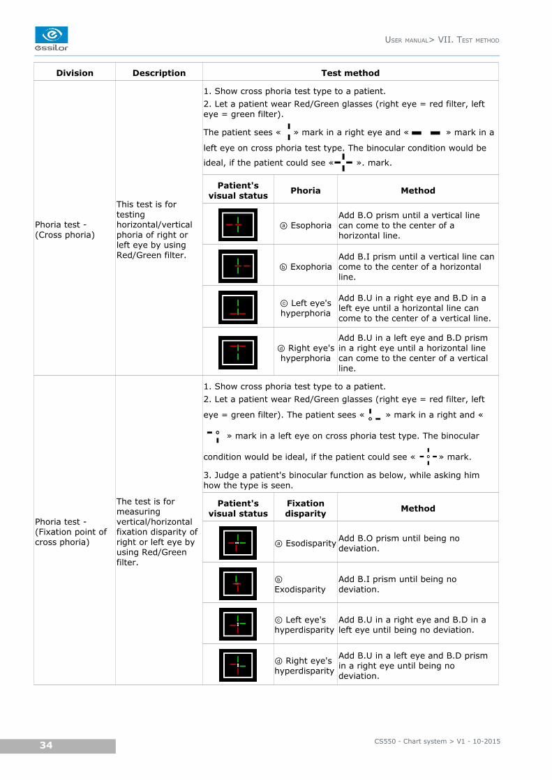
Phoria test - (Cross phoria)
This test is for testing horizontal/vertical phoria of right or left eye by using Red/Green filter.
1. Show cross phoria test type to a patient.
2. Let a patient wear Red/Green glasses (right eye = red filter, left eye = green filter).
The patient sees « » mark in a right eye and « » mark in a
left eye on cross phoria test type. The binocular condition would be
ideal, if the patient could see « ». mark.
Patient'svisual status
Phoria Method
EsophoriaⓐAdd B.O prism until a vertical line can come to the center of a horizontal line.
ExophoriaⓑAdd B.I prism until a vertical line can come to the center of a horizontal line.
Left eye'sⓒhyperphoria
Add B.U in a right eye and B.D in a left eye until a horizontal line can come to the center of a vertical line.
Right eye'sⓓhyperphoria
Add B.U in a left eye and B.D prism in a right eye until a horizontal line can come to the center of a vertical line.
Phoria test - (Fixation point of cross phoria)
The test is for measuring vertical/horizontal fixation disparity of right or left eye by using Red/Green filter.
1. Show cross phoria test type to a patient.
2. Let a patient wear Red/Green glasses (right eye = red filter, left
eye = green filter). The patient sees « » mark in a right and «
» mark in a left eye on cross phoria test type. The binocular
condition would be ideal, if the patient could see « » mark.
3. Judge a patient's binocular function as below, while asking him how the type is seen.
Patient'svisual status
Fixationdisparity
Method
Esodisparityⓐ Add B.O prism until being no deviation.
ⓑExodisparity
Add B.I prism until being no deviation.
Left eye's ⓒhyperdisparity
Add B.U in a right eye and B.D in a left eye until being no deviation.
Right eye's ⓓhyperdisparity
Add B.U in a left eye and B.D prism in a right eye until being no deviation.
CS550 - Chart system > V1 - 10-201534
USER MANUAL> VII. TEST METHOD
Division Description Test method
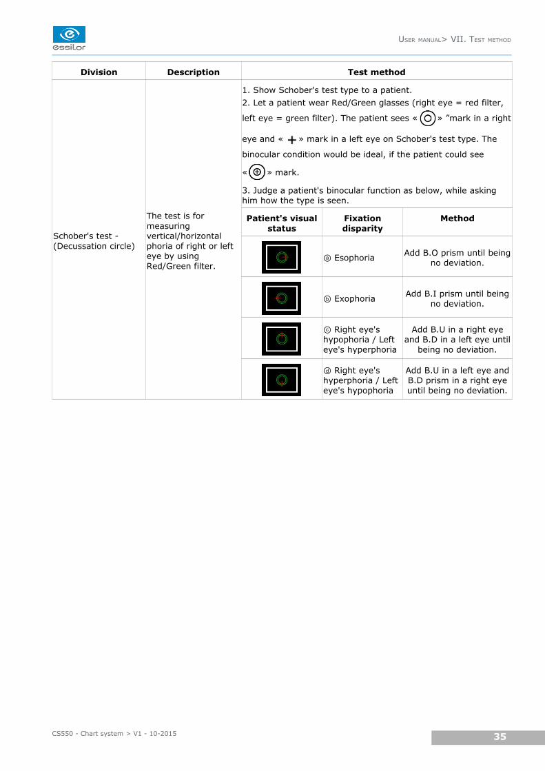
Schober's test - (Decussation circle)
The test is for measuring vertical/horizontal phoria of right or left eye by using Red/Green filter.
1. Show Schober's test type to a patient.
2. Let a patient wear Red/Green glasses (right eye = red filter,
left eye = green filter). The patient sees « » ”mark in a right
eye and « » mark in a left eye on Schober's test type. The
binocular condition would be ideal, if the patient could see
« » mark.
3. Judge a patient's binocular function as below, while asking him how the type is seen.
Patient's visualstatus
Fixationdisparity
Method
Esophoriaⓐ Add B.O prism until beingno deviation.
Exophoriaⓑ Add B.I prism until beingno deviation.
Right eye's ⓒhypophoria / Left eye's hyperphoria
Add B.U in a right eyeand B.D in a left eye until
being no deviation.
Right eye's ⓓhyperphoria / Left eye's hypophoria
Add B.U in a left eye andB.D prism in a right eyeuntil being no deviation.
USER MANUAL> VII. TEST METHOD
35CS550 - Chart system > V1 - 10-2015

VIII. REMOTE CONTROL FUNCTION
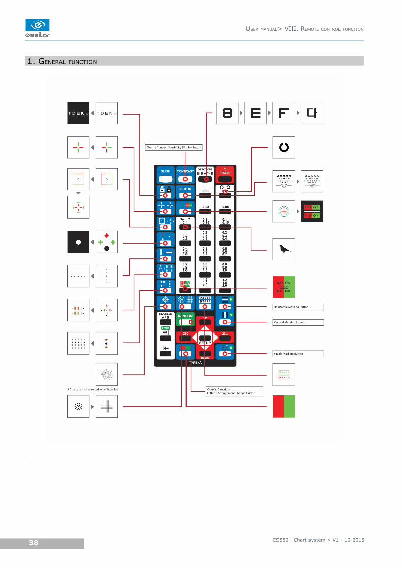
1. GENERAL FUNCTION
CS550 - Chart system > V1 - 10-201538
USER MANUAL> VIII. REMOTE CONTROL FUNCTION
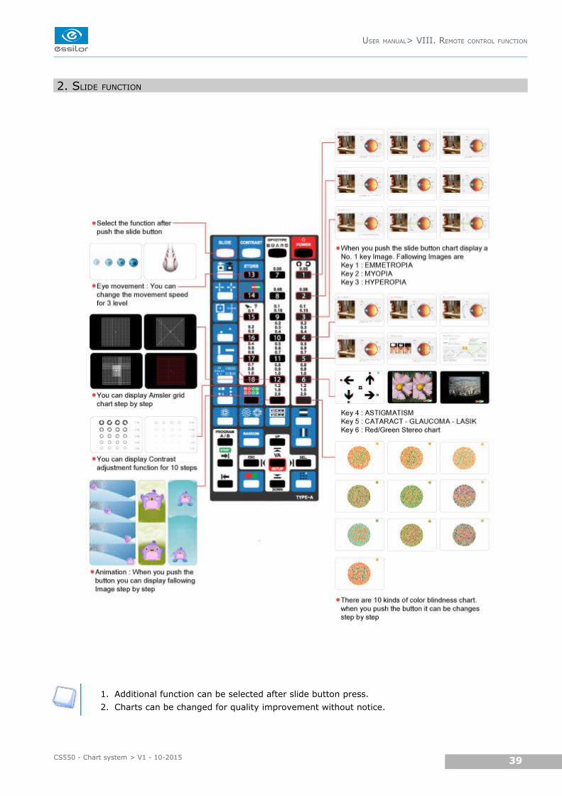
2. SLIDE FUNCTION
1. Additional function can be selected after slide button press.
2. Charts can be changed for quality improvement without notice.
USER MANUAL> VIII. REMOTE CONTROL FUNCTION
39CS550 - Chart system > V1 - 10-2015
IX. HOW TO RECHARGE A REMOTE CONTROL
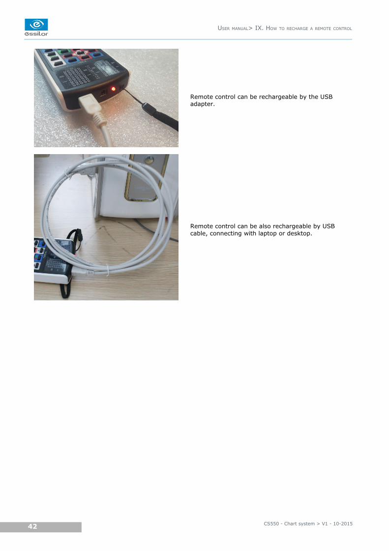
Remote control can be rechargeable by the USB adapter.
Remote control can be also rechargeable by USB cable, connecting with laptop or desktop.
CS550 - Chart system > V1 - 10-201542
USER MANUAL> IX. HOW TO RECHARGE A REMOTE CONTROL

X. CLEANING THE PRODUCT

Use a soft cloth with 90% Isopropyl Alcohol to clean the product's screen and the unit.
Cleaning of the product should be performed when its screen is contaminated or dust level is bad in visual.
Do not use paper towels.
CS550 - Chart system > V1 - 10-201544
USER MANUAL> X. CLEANING THE PRODUCT
XI. TROUBLESHOOTING GUIDE
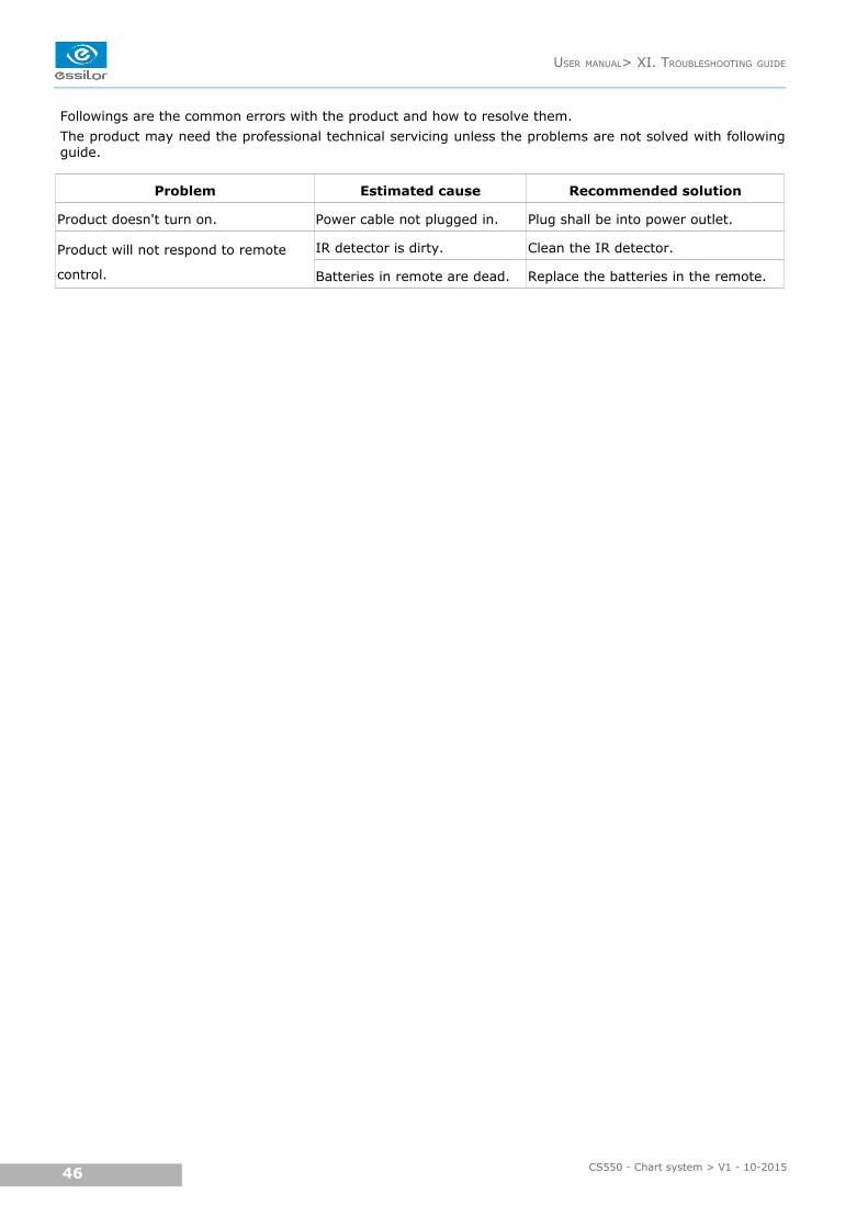
Followings are the common errors with the product and how to resolve them.
The product may need the professional technical servicing unless the problems are not solved with followingguide.
Problem Estimated cause Recommended solution
Product doesn't turn on. Power cable not plugged in. Plug shall be into power outlet.
Product will not respond to remote
control.
IR detector is dirty. Clean the IR detector.
Batteries in remote are dead. Replace the batteries in the remote.
CS550 - Chart system > V1 - 10-201546
USER MANUAL> XI. TROUBLESHOOTING GUIDE

XII. ENVIRONMENTAL CONDITIONS
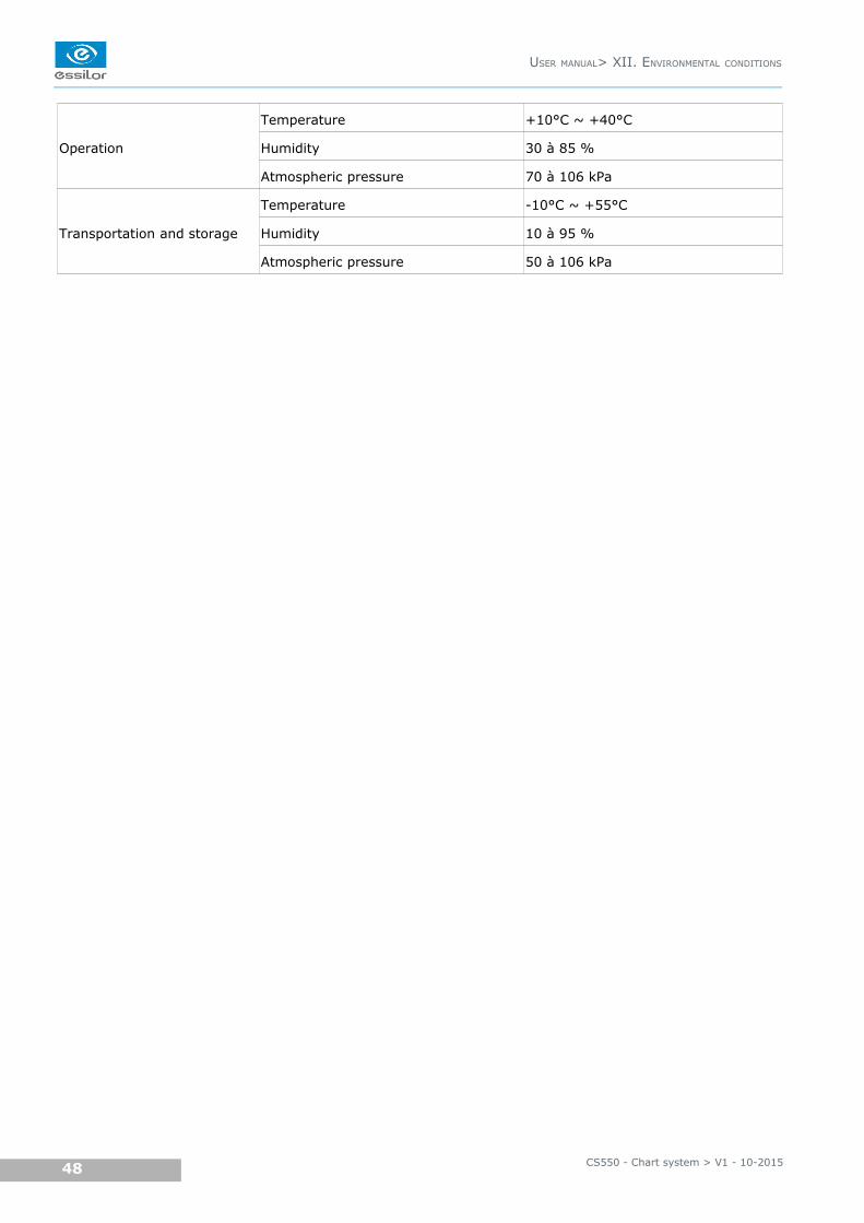
Operation
Temperature +10°C ~ +40°C
Humidity 30 à 85 %
Atmospheric pressure 70 à 106 kPa
Transportation and storage
Temperature -10°C ~ +55°C
Humidity 10 à 95 %
Atmospheric pressure 50 à 106 kPa
CS550 - Chart system > V1 - 10-201548
USER MANUAL> XII. ENVIRONMENTAL CONDITIONS
XIII. SPECIFICATIONS
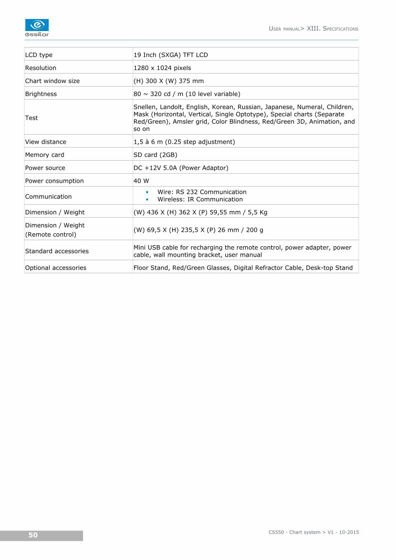
LCD type 19 Inch (SXGA) TFT LCD
Resolution 1280 x 1024 pixels
Chart window size (H) 300 X (W) 375 mm
Brightness 80 ~ 320 cd / m (10 level variable)
Test
Snellen, Landolt, English, Korean, Russian, Japanese, Numeral, Children, Mask (Horizontal, Vertical, Single Optotype), Special charts (Separate Red/Green), Amsler grid, Color Blindness, Red/Green 3D, Animation, and so on
View distance 1,5 à 6 m (0.25 step adjustment)
Memory card SD card (2GB)
Power source DC +12V 5.0A (Power Adaptor)
Power consumption 40 W
Communication• Wire: RS 232 Communication• Wireless: IR Communication
Dimension / Weight (W) 436 X (H) 362 X (P) 59,55 mm / 5,5 Kg
Dimension / Weight
(Remote control)(W) 69,5 X (H) 235,5 X (P) 26 mm / 200 g
Standard accessoriesMini USB cable for recharging the remote control, power adapter, power cable, wall mounting bracket, user manual
Optional accessories Floor Stand, Red/Green Glasses, Digital Refractor Cable, Desk-top Stand
CS550 - Chart system > V1 - 10-201550
USER MANUAL> XIII. SPECIFICATIONS

XIV. COMPONENTS LIST
1. STANDARD ACCESSORIES
Mini USB cable for recharging the remote control, power adapter, power cable, wall mounting bracket, user
manual.
2. OPTIONAL ACCESSORIES
Floor stand, Red/Green glasses, digital refractor cable, desktop stand.
CS550 - Chart system > V1 - 10-201552
USER MANUAL> XIV. COMPONENTS LIST

XV. SERVICE INFORMATION
If there are any problems with the product, please follow the below steps.
1. Turn off the power.
2. Remove the power cable connected to the equipment.
3. Remove SD card from the slot and install again.
Remark: Put SD card in right position when connect the slot.
4. Connect power adapter to the equipment and turn on the power.
5. Check if the equipment operates properly with remote control.
6. If the equipment does not operate properly, you are recommended to do as below.
◦ Check model name and serial number of the equipment and contact the distributor who you
purchased the equipment.
◦ If you can not contact the distributor, please contact as described below.
This product may malfunction due to the electromagnetic waves caused by cell phones, transceivers, radio-controlled toys, etc.
Be sure to avoid having objects such as, which affect this product brought near product.
1. REPAIR
If problem cannot be solved even after taking the measures indicated in section 15, contact your localrepresentative or distributor for repair.
Please refer to the name plate and let us have the following information:
• Name of the instrument: CS550
• Serial number: characters indicated on the name plate
• Detailed defects
CS550 - Chart system > V1 - 10-201554
USER MANUAL> XV. SERVICE INFORMATION

Essilor Instruments USA8600 W. Catalpa Avenue, Suite 703 Chicago, IL 60656Phone: 855.393.4647Email: [email protected] www.essilorinstrumentsusa.com
Related Documents