Phylink Covert Network Camera PLC-128PW/PLC-129PW V2.0 Please read this manual carefully before attempting to install or operate this product. This User Manual is a work-in-progress and is constantly being updated. You are invited to check the website regularly for updated versions. This manual applies to the following Phylink products. User Manual - English

Welcome message from author
This document is posted to help you gain knowledge. Please leave a comment to let me know what you think about it! Share it to your friends and learn new things together.
Transcript
Phylink Covert Network Camera PLC-128PW/PLC-129PW
V2.0
Please read this manual carefully before attempting to install or operate this product. This User Manual is a work-in-progress and is constantly being updated. You are invited to check the website regularly for updated versions.
This manual applies to the following Phylink products.
User Manual - English
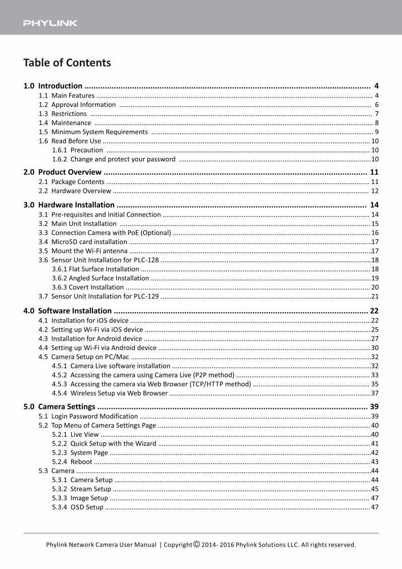
Table of Contents
| Copyright 2014- 2016 Phylink Solutions LLC. All rights reserved.Phylink Network Camera User Manual
3.0 Hardware Installation ..............................................................................................................3.1 Pre-requisites and Initial Connection ..............................................................................................................
3.2 Main Unit Installation .....................................................................................................................................
3.3 Connection Camera with PoE (Optional) .........................................................................................................
3.4 MicroSD card installation .................................................................................................................................
3.5 Mount the Wi-Fi antenna .................................................................................................................................
3.6 Sensor Unit Installation for PLC-128 ................................................................................................................
3.6.1 Flat Surface Installation ..........................................................................................................................
3.6.2 Angled Surface Installation .....................................................................................................................
3.6.3 Covert Installation ..................................................................................................................................
3.7 Sensor Unit Installation for PLC-129 ................................................................................................................
2.0 Product Overview ....................................................................................................................2.1 Package Contents ............................................................................................................................................
2.2 Hardware Overview ........................................................................................................................................
1.0 Introduction ..............................................................................................................................1.1 Main Features ...................................................................................................................................................
1.2 Approval Information ......................................................................................................................................
1.3 Restrictions ......................................................................................................................................................
1.4 Maintenance ....................................................................................................................................................
1.5 Minimum System Requirements ......................................................................................................................
1.6 Read Before Use ..............................................................................................................................................
1.6.1 Precaution ............................................................................................................................................
1.6.2 Change and protect your password ......................................................................................................
4.0 Software Installation ................................................................................................................4.1 Installation for iOS device ................................................................................................................................
4.2 Setting up Wi-Fi via iOS device ........................................................................................................................
4.3 Installation for Android device .........................................................................................................................
4.4 Setting up Wi-Fi via Android device .................................................................................................................
4.5 Camera Setup on PC/Mac ................................................................................................................................
4.5.1 Camera Live software installation ..........................................................................................................
4.5.2 Accessing the camera using Camera Live (P2P method) .......................................................................
4.5.3 Accessing the camera via Web Browser (TCP/HTTP method) ..............................................................
4.5.4 Wireless Setup via Web Browser ...........................................................................................................
5.0 Camera Settings .......................................................................................................................5.1 Login Password Modification ...........................................................................................................................
5.2 Top Menu of Camera Settings Page .................................................................................................................
5.2.1 Live View ................................................................................................................................................
5.2.2 Quick Setup with the Wizard .................................................................................................................
5.2.3 System Page ...........................................................................................................................................
5.2.4 Reboot ...................................................................................................................................................
5.3 Camera .............................................................................................................................................................
5.3.1 Camera Setup ........................................................................................................................................
5.3.2 Stream Setup .........................................................................................................................................
5.3.3 Image Setup ..........................................................................................................................................
5.3.4 OSD Setup .............................................................................................................................................
3939
40
40
41
42
43
44
44
45
47
47
44
6
7
8
9
10
10
10
1111
12
1414
15
16
17
17
18
18
19
20
21
2222
25
27
30
32
32
33
35
37
| Copyright 2014- 2016 Phylink Solutions LLC. All rights reserved.Phylink Network Camera User Manual
5.4 Network ...........................................................................................................................................................
5.4.1 Wireless Setup .......................................................................................................................................
5.4.2 TCP/IP Setup .........................................................................................................................................
5.4.3 DDNS Setup ..........................................................................................................................................
5.4.4 UPnP Setup ...........................................................................................................................................
5.4.5 P2P Setup ..............................................................................................................................................
5.5 Storage .............................................................................................................................................................
5.5.1 Storage Setup ........................................................................................................................................
5.5.2 Browse Storage .....................................................................................................................................
5.5.3 Format SD Card .....................................................................................................................................
5.6 Task ................................................................................................................................................................
5.6.1 Global On/Off .......................................................................................................................................
5.6.2 Motion Detection .................................................................................................................................
5.6.3 Schedule Setup ......................................................................................................................................
5.6.4 Task Management .................................................................................................................................
5.6.4.1 E-mail alarm sending ..................................................................................................................
5.6.4.2 Email periodic sending ...............................................................................................................
5.6.4.3 FTP Alarm Sending ....................................................................................................................
5.6.4.4 FTP Periodic Sending .................................................................................................................
5.6.4.5 HTTP Alarm Sending ..................................................................................................................
5.6.4.6 HTTP Periodic Sending ...............................................................................................................
5.6.4.7 Snapshot to storage on alarm ....................................................................................................
5.6.4.8 Snapshot to storage periodically ................................................................................................
5.6.4.9 Record to storage on alarm ........................................................................................................
5.6.4.10 Record to Storage Continuously ...............................................................................................
5.6.4.11 Send files in Storage to FTP Server ...........................................................................................
5.6.4.12 Push Notification ......................................................................................................................
5.7 Tools ................................................................................................................................................................
5.7.1 System Identity ......................................................................................................................................
5.7.2 User Management .................................................................................................................................
5.7.3 Date & Time ...........................................................................................................................................
5.7.4 Backup and Reset ..................................................................................................................................
5.7.5 Watchdog Setup ...................................................................................................................................
5.7.6 Firmware Upgrade ................................................................................................................................
8.0 Appendix .................................................................................................................................Appendix A: A Quick Review of Networking Terminology .....................................................................................
Appendix B: Resetting the Camera back to Factory Settings .................................................................................
Appendix C: Connecting your Camera directly to a Computer ..............................................................................
Appendix D: Recovering from a failed Firmware update using Windows .............................................................
Appendix E: Manually entering TCP/IP Settings for a Camera ..............................................................................
Appendix F: Wireless Installation Considerations ..................................................................................................
Appendix G: Setting up the Camera over WiFi using WPS ....................................................................................
Appendix H: Burglar Alarm System integration with Digital I/O ............................................................................
9.0 Contact Us ...............................................................................................................................
50
50
52
54
55
56
57
57
59
60
61
61
61
64
65
66
67
68
69
70
70
71
71
72
73
74
75
76
76
76
77
78
78
79
98
8585
86
87
88
90
92
93
94
6.0 Troubleshooting .......................................................................................................................
7.0 Glossary of Terms .....................................................................................................................
81
83
1.0 Introduction
Thank you for purchasing a Phylink network video camera
This 2.4GHz wireless camera meets wireless frequency security standards and recommended indexes during operation.
These standards and indexes are certificated by the academic organization as illustrated in the following paragraphs.
Product Assurance
| Copyright 2014- 2016 Phylink Solutions LLC. All rights reserved.Phylink Network Camera User Manual
The Phylink Covert Network Camera can be accessed remotely and also controlled from any PC/laptop over an
Intranet/Internet via a web browser. The user friendly installation procedure and intuitive web-based interface allow
easy integration with your home or business network or Wi-Fi. The camera also comes with motion detection
software which can generate alarm triggers via e-mail and upload images straightly to a website. From our
experience, we find that our customers get comfortable with these advanced features quickly and then start using the
camera on a daily basis to keep in touch with their home or loved ones.
You can view very high quality live streaming video directly from the camera by using a Mac or PC. It works excellently
as a baby monitor, nanny cam, pet cam, party cam, security & surveillance, remote observation, elder and patient
care as well as limited video conferencing or event broadcasting.
An exciting new feature is the ability to turn your iPhone, iPad iOS device and Android OS smartphone, Tablet into a
baby monitor without any professional installer, Extra wires, IP address setting, DDNS address setting or router
setting. It is simply just plug and play.
1.1 Main Features
Easy InstallationThe camera comes with built-in Wireless (IEEE802.11b/g/n) capability and a Web Server, therefore there is no need
to install a driver. The setup includes the Camera Setup software, User Manual and Quick Installation Guide. With
industry standard automatic configuration -UPnP (Universal Plug and Play), your PC will discover and connect to your
camera automatically. Once successfully connected, you can see what the camera sees from anywhere in the world
using a simple web browser.
802.11b/g/n Wireless LAN Connection AvailableThe camera is designed to not only work with your existing wired network but also with standard 802.11b/g/n
wireless devices, allowing the flexibility to operate the camera wirelessly. The camera utilizes SSID filtering, powerful
64/128 bit WEP and new security standard WPA encryption to protect you from illegal intrusion.
Simultaneous High-Speed MPEG-4 and Motion JPEGThe camera allows live MPEG-4 and Motion JPEG streams simultaneously. The camera features H.264/MPEG4
compression which compresses the video to make transmission faster and more efficient. The H.264/MPEG4 and
MJPEG image can be transmitted at 30 frames per second.
Simultaneous HTTP and RTSP streamingThe camera supports HTTP and RTSP/RTP/RTCP protocol as well as provides multiple HTTP and RTSP streams
simultaneously.
Audio TransmissionThe camera comes with a built-in microphone for audio monitoring as well as video monitoring. Sound captured by
the camera can be transmitted to the client’s PC.
4
OSD FunctionOSD (On Screen Display) function can display system name, date and time and user-defined on screen.
AuthenticationAn authentication window requires you to enter the user ID and password. Password security can prevent
unregistered users from accessing your camera. Users can select Basic Authentication method or Digest Access
Authentication method.
Multi-Client AccessThe camera allows up to 16 users to view the video simultaneously. Please note that it is possible that as the number
of simultaneously connected users to camera increases, the overall motion performance will decrease.
Snapshot and RecordingYou can capture a still image of the camera view on your PC and save the image as JPG or BMP format file. You also
can record the video and audio captured by the camera on your PC and save as an ASF format file.
| Copyright 2014- 2016 Phylink Solutions LLC. All rights reserved.Phylink Network Camera User Manual
Motion Detection FunctionThe camera can detect changes in the image being monitored. Once a change occurs, it will send an email to up to 3
e-mail addresses with a snapshot attached. The video file or snapshot can also be uploaded to an FTP server. In
addition the camera can be configured to send images at regular intervals.
5
1.2 Approval Information
All our products meet the requirements for approval by FCC and CE, and are authorized to bear the FCC and CE mark.
FCC Statement
CE Statement
This product complies with standards including Low Voltage Device Directive 73/23/EEC; EMC Directive 89/336/EEC
and R&TTE Directive 1999/5/EC. It passed the subject tests by the authority concerned and is authorized to bear CE
mark.
CE Mark Warning
This is a Class A product. In a domestic environment, this product may cause radio interference, in which case the
user may be required to take adequate measures.
| Copyright 2014- 2016 Phylink Solutions LLC. All rights reserved.Phylink Network Camera User Manual
This equipment has been tested and found to comply with the limits for a Class B digital device, pursuant to Part 15 of
the FCC rules. These limits are designed to provide reasonable protection against harmful interference in a residential
installation. This equipment generates, uses and radiates radio frequency energy and if not installed and used in
accordance with the instructions, may cause harmful interference to radio communications. However, there is no
guarantee that interference will not occur in a particular installation. If this equipment does cause harmful
interference to radio or television reception, which can be determined by turning the equipment off and on, the user
is encouraged to try to correct the interference by one or more of the following measures: -Reorient or relocate the
receiving antenna. -Increase the separation between the equipment and the receiver. -Connect the equipment into
an outlet on a circuit different from that to which the receiver is connected. -Consult the dealer or an experienced
radio/TV technician for help.
This device complies with Part 15 of the FCC Rules. Operation is subject to the following two conditions:
(1) This device may not cause harmful interference, and
(2) This device must accept any interference received, including interference that may cause undesired operation
Changes and modification not expressly approved by the manufacturer or registrant of this equipment can void your
authority to operate this equipment under Federal Communications Commissions rules.
6
1.3 Restrictions
1. DO NOT use this product to violate one's privacy. Monitoring one's activities without consent is illegal and this
product is not designed and manufactured for such purpose.
2. DO NOT put this product near any medical equipment. Radio waves might potentially cause breakdown of
electrical medical equipment.
3. This product should be placed at least one foot away from any heart pacemaker. Radio waves might potentially
influence a heart pacemaker.
5. Do NOT install near any heat sources such as radiators, heat registers, stoves, or other apparatus that produce
heat.
WARNING:The indoor camera is not workable for outdoor use. It can only be installed indoors. Damage caused by water is not
covered by warranty.
The Power Adaptor supplied is not interchangeable.
It should not be used with other product, and may
cause product failure for other products.
| Copyright 2014- 2016 Phylink Solutions LLC. All rights reserved.Phylink Network Camera User Manual
4. DO NOT use this product for any illegal activities. User’s are responsible for ensuring that the usage of this
camera does not violate any legality concerns.
6. Do NOT expose this apparatus to rain or moisture in order to reduce the risk of fire or electric shock. The apparatus
shall not be exposed to dripping or splashing. Also, objects filled with liquids, such as vases, shall not be placed on the
apparatus.
7
1.4 Maintenance
Notice
This product may cause interference with other wireless equipment that operate at 2.4GHz ISM band. In the event of
interference please turn off one of the devices or move it to a safe distance.
1. Ensure that the camera and its power source have sufficient ventilation.
2. Do not shake, strike or drop the product.
3. Keep the camera dry and dustless and avoid exposing it to direct sunlight.
4. Do not place the product near any magnetic objects.
5. Avoid putting the product in places where there is constant change in temperature and humidity
6. Keep the product away from heat sources.
7. Do not use the camera near aggressive chemicals.
8. Do not use this camera near water (unless the camera is specified as waterproof).
9. Do not use the camera in the places which are enclosed by metal. The surrounding metal may shield the
electromagnetic waves, and result in failure of signal reception.
10. Please follow your local government environment protection policies.
11. Please turn off the power when left unused.
12. Do not disassemble or attempt to repair the camera; doing so might cause damage to the product and will
invalidate warranty.
| Copyright 2014- 2016 Phylink Solutions LLC. All rights reserved.Phylink Network Camera User Manual
8
1.5 Minimum System Requirements
A PC or Mac is required for the initial setup of camera only and once the camera is configured, it can be used
independently without being connected to a computer.
• Network Connection: 10/100 Mbps Ethernet
• Wireless router (if wireless connectivity required)
• Broadband Connection: Minimum 128kb/s upload speed (if internet access to your camera is required)
Network requirements:
PC Requirements:
• Processor: Intel Pentium III, 800MHz or Higher (Pentium IV, 2GHz or higher recommended)
• Memory (RAM): 128Mb (256Mb or higher recommended).
• Operating System: Windows 2000, XP, Vista, Windows 7
• Web Browser: Internet Explorer Version 5.5 or above, Mozilla Firefox, Google Chrome.
• Plug-ins: Adobe flash (for non-IE browsers)
Mac Requirements:
• Processor: 800MHz - PowerPC G4 or Intel.
• Memory (RAM): 128Mb (256Mb or higher recommended).
• Operating System: Mac OSX 10.4 Tiger.
• Web Browser: Safari, Mozilla Firefox, Google Chrome and most other browsers
• Plug-ins: Adobe flash
Web Browser Compatibility:
| Copyright 2014- 2016 Phylink Solutions LLC. All rights reserved.Phylink Network Camera User Manual
Tips:Please note that browser itself does not support video decoding and playback, it needs to install plug-ins player.
To play the live video of camera, the web browser needs to install the flash player plug-ins for Chrome and Safari or
ActiveX Control for Internet Explorer.
If you are trying to view the camera for the first time using Internet Explorer, your browser may prompt you to install
or allow an "ActiveX Control".
If you are trying to view the camera for the first time using Chrome or Firefox, your browser will prompt you to install
or allow the “Adobe Flash Plug-in”.
You can access the camera via various web browser. Phylink cameras work on most web browsers such as Firefox,
Internet Explorer, Microsoft Edge (Windows 10), Chrome and Safari.
9
1.6 Read Before Use
The camera comes with a default login and password. Please setup the camera using those defaults. You can then
login and change the admin login/password to something more secure once it has been installed.
If you are installing the camera for the first time or after a reset to factory defaults, you are advised to change the
cameras default password as per the message displayed. Changing the cameras default password is highly
recommended to avoid unauthorized access to your camera.
Also please protect your camera's login password, just like your bank password or email password.
1. The use of surveillance devices may be prohibited by law in your country. The Network Camera is not only a high-
performance web-ready camera but can also be part of a flexible surveillance system. It is the user’s responsibility to
ensure that the operation of such devices is legal before installing this unit for its intended use.
1.6.1 Precaution
1.6.2 Change and protect your password
2. Do not disassemble or attempt to repair the camera; doing so might cause damage to the product and will
invalidate warranty.
3. Do not install the product on unstable brackets, unstable or vibrating surfaces since this could cause damage to the
product.
4. Please read the hardware installation instructions in this manual carefully before attempting to install or use the
camera.
| Copyright 2014- 2016 Phylink Solutions LLC. All rights reserved.Phylink Network Camera User Manual
To learn how to change the login password, please go to ” chapter in this manual.“Login Password Modification
All Phylink camera secured with the top secure AES(Advanced Encryption Standard) encryption, 128 bit secret key
(AES) are used for digital video encryption, ensuring that all data sent between the user and the camera is encrypted,
which prevents someone from accessing the information while it is in transit.
10
2.0 Product Overview
2.1 Package Contents
| Copyright 2014- 2016 Phylink Solutions LLC. All rights reserved.Phylink Network Camera User Manual
- PLC-128PW / PLC-129PW Main Unit
- Camera Unit ( include 6 meter RJ11 cable)
- Mounting Accessories
- External Antenna (PLC-128P has no this item)
- Manual and Software on CD-ROM
- CAT5 Ethernet Cable for initial Setup
- 4 pin I/O connector terminal block
- Power Adapter
- Quick Install Guide
It is important to verify first that all contents received are complete according to the Package Contents listed below.
Take note of the warnings in the Quick Installation Guide before the Network Camera is installed; then carefully read
and follow the instructions in the Installation chapter to avoid damage due to faulty assembly and installation. This
also ensures the product is used properly as intended.
11
1 2
CAMLine In/MIC
15
14
17
16 18
9
10
11
Mounting Accessories for PLC-128
4 7
5
3
6
7
8
13
12
19
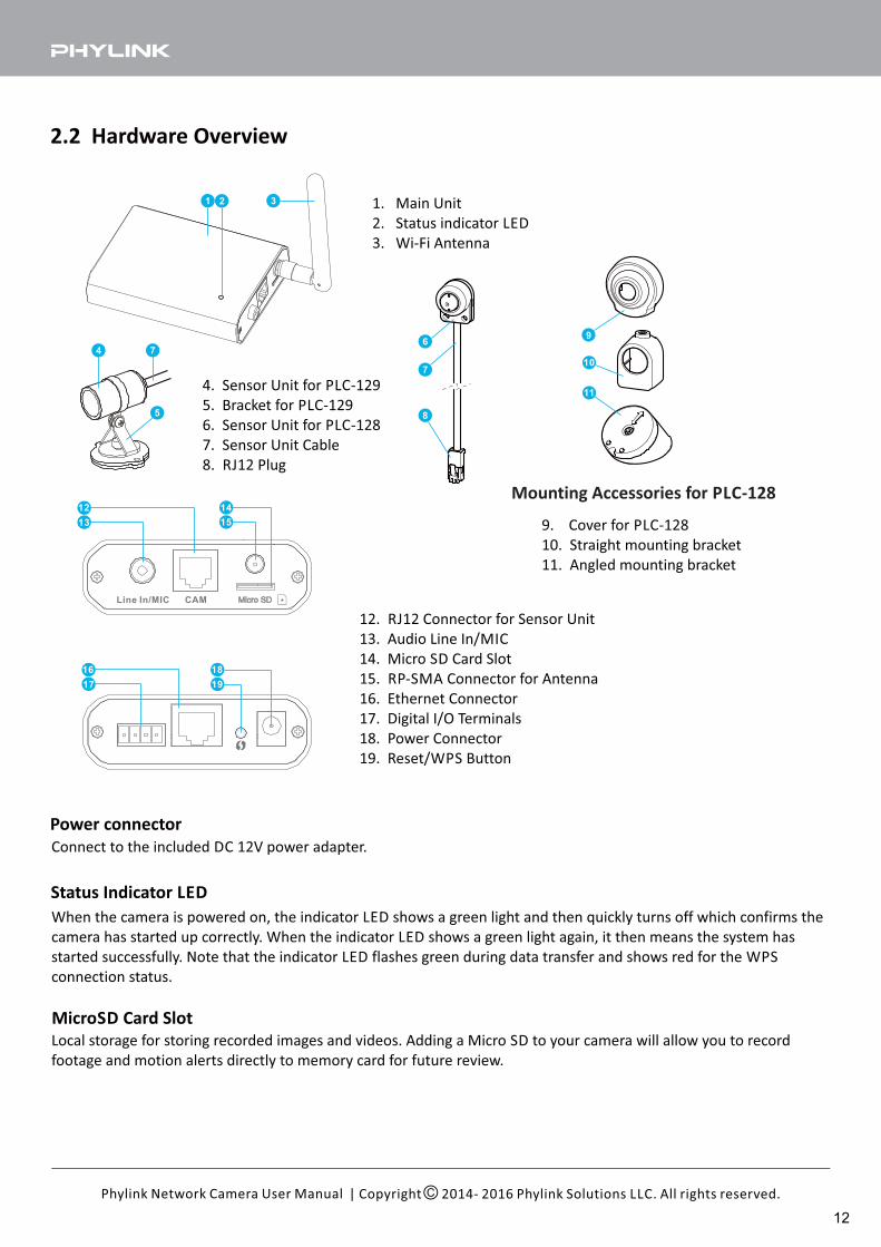
2.2 Hardware Overview
| Copyright 2014- 2016 Phylink Solutions LLC. All rights reserved.Phylink Network Camera User Manual
Power connector
Connect to the included DC 12V power adapter.
4. Sensor Unit for PLC-129
5. Bracket for PLC-129
6. Sensor Unit for PLC-128
7. Sensor Unit Cable
8. RJ12 Plug
1. Main Unit
2. Status indicator LED
3. Wi-Fi Antenna
9. Cover for PLC-128
10. Straight mounting bracket
11. Angled mounting bracket
12. RJ12 Connector for Sensor Unit
13. Audio Line In/MIC
14. Micro SD Card Slot
15. RP-SMA Connector for Antenna
16. Ethernet Connector
17. Digital I/O Terminals
18. Power Connector
19. Reset/WPS Button
Status Indicator LED
MicroSD Card Slot
Local storage for storing recorded images and videos. Adding a Micro SD to your camera will allow you to record
footage and motion alerts directly to memory card for future review.
When the camera is powered on, the indicator LED shows a green light and then quickly turns off which confirms the
camera has started up correctly. When the indicator LED shows a green light again, it then means the system has
started successfully. Note that the indicator LED flashes green during data transfer and shows red for the WPS
connection status.
12
NOTICE
| Copyright 2014- 2016 Phylink Solutions LLC. All rights reserved.Phylink Network Camera User Manual
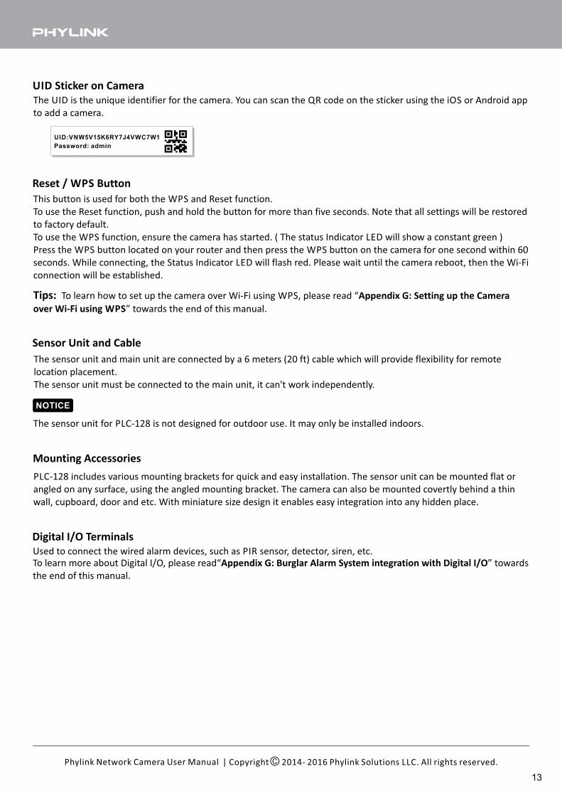
UID Sticker on Camera
The UID is the unique identifier for the camera. You can scan the QR code on the sticker using the iOS or Android app
to add a camera.
UID:VNW5V15K6RY7J4VWC7W1
Password: admin
Reset / WPS Button
This button is used for both the WPS and Reset function.
To use the Reset function, push and hold the button for more than five seconds. Note that all settings will be restored
to factory default.
To use the WPS function, ensure the camera has started. ( The status Indicator LED will show a constant green )
Press the WPS button located on your router and then press the WPS button on the camera for one second within 60
seconds. While connecting, the Status Indicator LED will flash red. Please wait until the camera reboot, then the Wi-Fi
connection will be established.
Sensor Unit and Cable
The sensor unit and main unit are connected by a 6 meters (20 ft) cable which will provide flexibility for remote
location placement.
The sensor unit must be connected to the main unit, it can't work independently.
The sensor unit for PLC-128 is not designed for outdoor use. It may only be installed indoors.
Mounting Accessories
PLC-128 includes various mounting brackets for quick and easy installation. The sensor unit can be mounted flat or
angled on any surface, using the angled mounting bracket. The camera can also be mounted covertly behind a thin
wall, cupboard, door and etc. With miniature size design it enables easy integration into any hidden place.
Digital I/O Terminals
Used to connect the wired alarm devices, such as PIR sensor, detector, siren, etc.
Tips: To learn how to set up the camera over Wi-Fi using WPS, please read “Appendix G: Setting up the Camera
over Wi-Fi using WPS” towards the end of this manual.
To learn more about Digital I/O, please read“ ” towardsAppendix G: Burglar Alarm System integration with Digital I/O
the end of this manual.
13
| Copyright 2014- 2016 Phylink Solutions LLC. All rights reserved.Phylink Network Camera User Manual
3.0 Hardware Installation
3.1 Pre-requisites and Initial Connection
All cameras come with a Cat5e network cable for initial connection of the camera to one of the LAN jacks of your
router. Should you wish to set up wireless operation, this initial wired connection is required to tell the camera what
your wireless network name and password is.
IMPORTANT: Make sure the Cat5 network cable is plugged into your router, not the computer, even
if your computer has a network jack. If you don’t have a router you’d need to get one, as this is one
of the few prerequisites.
You can start using the camera on your own network immediately after powering the camera up and connecting the
Cat5 cable to your router.
Besides the camera itself, and power adapter for the camera, you only need:
1. An iOS or Android mobile phone.
You can setup the camera easily without computer.
2. PC, Mac, or Linux computer with internet browser. (This is optional)
The computer is only required for initial setup. Later the camera can work by itself without any computer present
at the camera location.
3. A wired or wireless router with an available Cat5 wired network jack. For wireless cameras, your router’s wired
network connection is only needed for initial setup.
4. For standalone recording without a computer, you need a MicroSD or MicroSDHC memory card.
5. Phylink outdoor cameras have the PoE feature. For powering the camera you can choose to use the included AC
adapter or PoE injector/switch (Not included).
14
| Copyright 2014- 2016 Phylink Solutions LLC. All rights reserved.Phylink Network Camera User Manual
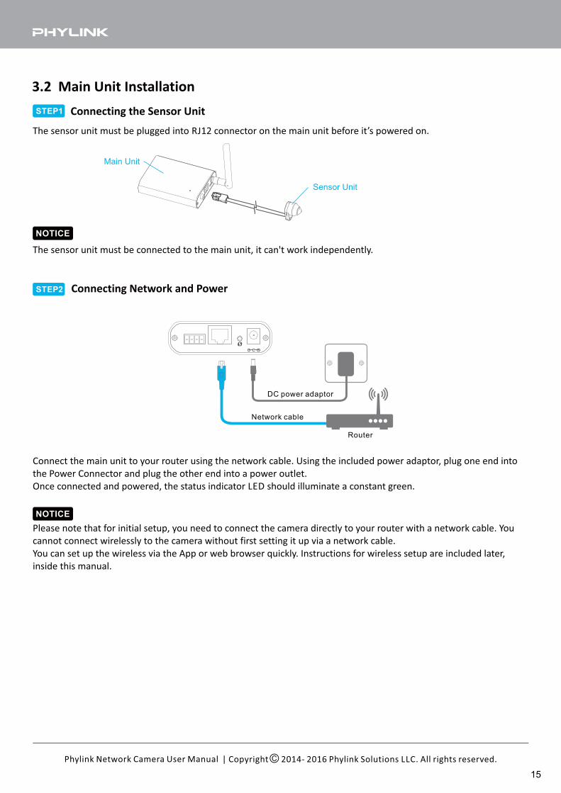
3.2 Main Unit Installation
Connect the main unit to your router using the network cable. Using the included power adaptor, plug one end into
the Power Connector and plug the other end into a power outlet.
Once connected and powered, the status indicator LED should illuminate a constant green.
NOTICE
Please note that for initial setup, you need to connect the camera directly to your router with a network cable. You
cannot connect wirelessly to the camera without first setting it up via a network cable.
You can set up the wireless via the App or web browser quickly. Instructions for wireless setup are included later,
inside this manual.
The sensor unit must be plugged into RJ12 connector on the main unit before it’s powered on.
Connecting the Sensor UnitSTEP1
Main Unit
Sensor Unit
NOTICE
The sensor unit must be connected to the main unit, it can't work independently.
STEP2 Connecting Network and Power
Network cable
Router
DC power adaptor
15
| Copyright 2014- 2016 Phylink Solutions LLC. All rights reserved.Phylink Network Camera User Manual
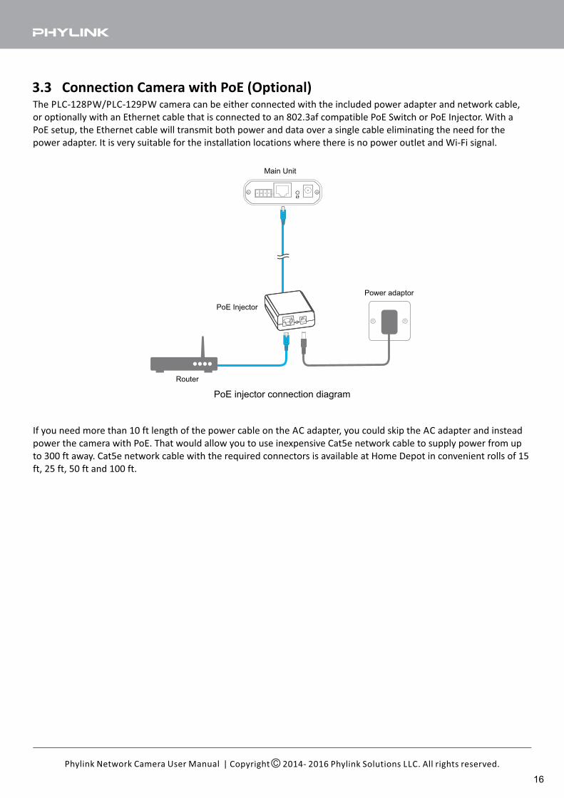
3.3 Connection Camera with PoE (Optional)The PLC-128PW/PLC-129PW camera can be either connected with the included power adapter and network cable,
or optionally with an Ethernet cable that is connected to an 802.3af compatible PoE Switch or PoE Injector. With a
PoE setup, the Ethernet cable will transmit both power and data over a single cable eliminating the need for the
power adapter. It is very suitable for the installation locations where there is no power outlet and Wi-Fi signal.
PoE Injector
PoE injector connection diagram
Power adaptor
If you need more than 10 ft length of the power cable on the AC adapter, you could skip the AC adapter and instead
power the camera with PoE. That would allow you to use inexpensive Cat5e network cable to supply power from up
to 300 ft away. Cat5e network cable with the required connectors is available at Home Depot in convenient rolls of 15
ft, 25 ft, 50 ft and 100 ft.
Router
Main Unit
16
| Copyright 2014- 2016 Phylink Solutions LLC. All rights reserved.Phylink Network Camera User Manual
3.4 MicroSD card installation
The Micro SD card is not included in packages. Adding a Micro SD card to your camera will allow you to record
footage and motion alerts directly to the MicroSD card for future review. The recorded files may be reviewed
remotely on your phone / computer when using Phylink app / software.
For a new SD card which has never been used or formatted, you can use the camera’s format tool to format it. To
learn how to format the SD card, please refer to the related technical articles on the Phylink support website.
The camera only supports the FAT32 file system; other formats will not be recognized. It is recommended to format
the Micro SD card via the format tools. You can download the format tools for FAT32 via the follows links:
http://www.phylink.com/downloads/download_file/tools/guiformat.zip
Or http://www.sdcard.org/downloads/index.html
NOTICE
The camera must be powered off before inserting the Micro SD card. The camera will only recognize the card if
inserted before startup. Every time the card is re-inserted, you will need to turn the power off and then turn the
power on again to recognize the SD card.
To insert the micro SD card, follow these steps:
1. Power off the camera as applicable.
2. Hold the MicroSD card with the printed side facing upward and the golden pins facing toward the MicroSD slot.
Press the MicroSD card into the slot until you hear a click.
Tip:
To learn more about MicroSD card installation and formatting, please refer to "How to setup recording to MicroSD
card Support - Technical Articles" in section from our technical support website.
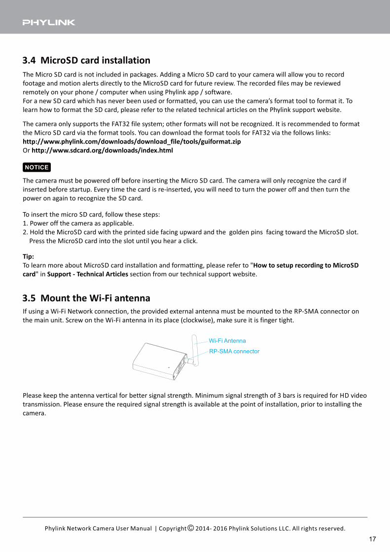
3.5 Mount the Wi-Fi antenna
If using a Wi-Fi Network connection, the provided external antenna must be mounted to the RP-SMA connector on
the main unit. Screw on the Wi-Fi antenna in its place (clockwise), make sure it is finger tight.
Please keep the antenna vertical for better signal strength. Minimum signal strength of 3 bars is required for HD video
transmission. Please ensure the required signal strength is available at the point of installation, prior to installing the
camera.
Wi-Fi Antenna
RP-SMA connector
17
| Copyright 2014- 2016 Phylink Solutions LLC. All rights reserved.Phylink Network Camera User Manual
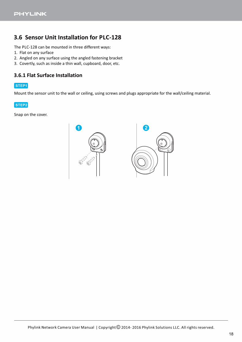
3.6 Sensor Unit Installation for PLC-128
The PLC-128 can be mounted in three different ways:
1. Flat on any surface
2. Angled on any surface using the angled fastening bracket
3. Covertly, such as inside a thin wall, cupboard, door, etc.
3.6.1 Flat Surface Installation
21
STEP1
STEP2
Mount the sensor unit to the wall or ceiling, using screws and plugs appropriate for the wall/ceiling material.
Snap on the cover.
18
| Copyright 2014- 2016 Phylink Solutions LLC. All rights reserved.Phylink Network Camera User Manual
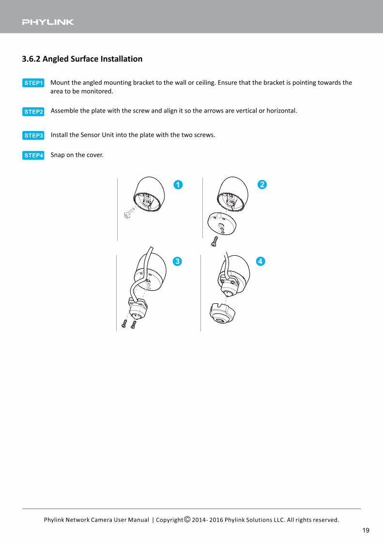
3.6.2 Angled Surface Installation
STEP1
STEP2
STEP3
STEP4
Mount the angled mounting bracket to the wall or ceiling. Ensure that the bracket is pointing towards the
area to be monitored.
Assemble the plate with the screw and align it so the arrows are vertical or horizontal.
Install the Sensor Unit into the plate with the two screws.
Snap on the cover.
21
3 4
19
| Copyright 2014- 2016 Phylink Solutions LLC. All rights reserved.Phylink Network Camera User Manual
3
21
STEP1
STEP2
STEP3
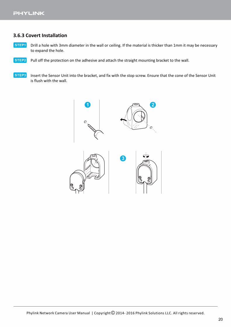
3.6.3 Covert Installation
Drill a hole with 3mm diameter in the wall or ceiling. If the material is thicker than 1mm it may be necessary
to expand the hole.
Pull off the protection on the adhesive and attach the straight mounting bracket to the wall.
Insert the Sensor Unit into the bracket, and fix with the stop screw. Ensure that the cone of the Sensor Unit
is flush with the wall.
20
| Copyright 2014- 2016 Phylink Solutions LLC. All rights reserved.Phylink Network Camera User Manual
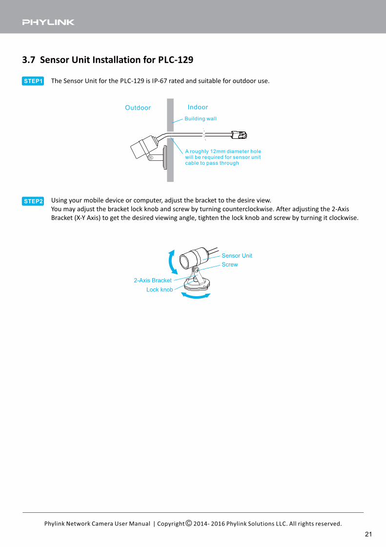
3.7 Sensor Unit Installation for PLC-129
STEP1
Outdoor Indoor
Building wall
A roughly 12mm diameter holewill be required for sensor unitcable to pass through
STEP2
Sensor Unit
2-Axis Bracket
Lock knob
Screw
The Sensor Unit for the PLC-129 is IP-67 rated and suitable for outdoor use.
Using your mobile device or computer, adjust the bracket to the desire view.
You may adjust the bracket lock knob and screw by turning counterclockwise. After adjusting the 2-Axis
Bracket (X-Y Axis) to get the desired viewing angle, tighten the lock knob and screw by turning it clockwise.
21
4.0 Software Installation
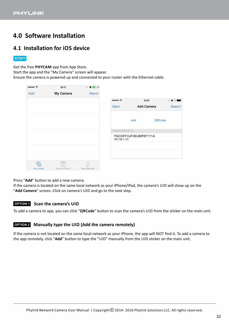
4.1 Installation for iOS device
STEP1
Get the free app from App Store.PHYCAM
Start the app and the "My Camera" screen will appear.
Ensure the camera is powered up and connected to your router with the Ethernet cable.
| Copyright 2014- 2016 Phylink Solutions LLC. All rights reserved.Phylink Network Camera User Manual
OPTION 1 Scan the camera’s UID
Manually type the UID (Add the camera remotely)
Press “ ” button to add a new camera.Add
If the camera is located on the same local network as your iPhone/iPad, the camera’s UID will show up on the
“ " screen. Click on camera's UID and go to the next step.Add Camera
To add a camera to app, you can click “ ” button to scan the camera’s UID from the sticker on the main unit.QRCode
OPTION 2
If the camera is not located on the same local network as your iPhone, the app will NOT find it. To add a camera to
the app remotely, click “ ” button to type the "UID" manually from the UID sticker on the main unit.Add
22
| Copyright 2014- 2016 Phylink Solutions LLC. All rights reserved.Phylink Network Camera User Manual
STEP2
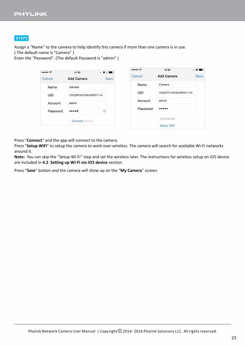
Assign a "Name" to the camera to help identify this camera if more than one camera is in use.
( The default name is "Camera" )
Enter the "Password". (The default Password is "admin" )
Press " " and the app will connect to the camera.Connect
Press " " to setup the camera to work over wireless. The camera will search for available Wi-Fi networksSetup WiFi
around it.
Note: You can skip the “Setup Wi-Fi” step and set the wireless later. The instructions for wireless setup on iOS device
are included in section.4.2 Setting up Wi-Fi via iOS device
Press " " button and the camera will show up on the “ ” screen.Save My Camera
23
| Copyright 2014- 2016 Phylink Solutions LLC. All rights reserved.Phylink Network Camera User Manual
STEP3
21
3
4
4
5
6
7
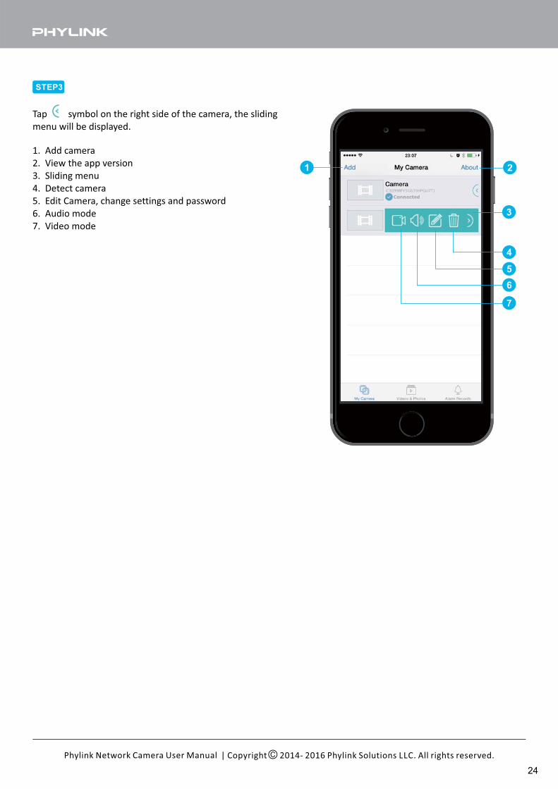
Tap symbol on the right side of the camera, the sliding
menu will be displayed.
1. Add camera
2. View the app version
3. Sliding menu
4. Detect camera
5. Edit Camera, change settings and password
6. Audio mode
7. Video mode
24
| Copyright 2014- 2016 Phylink Solutions LLC. All rights reserved.Phylink Network Camera User Manual
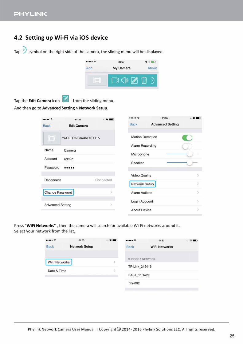
4.2 Setting up Wi-Fi via iOS device
Tap symbol on the right side of the camera, the sliding menu will be displayed.
Tap the icon from the sliding menu.Edit Camera
And then go to > .Advanced Setting Network Setup
Press “ ” , then the camera will search for available Wi-Fi networks around it.WiFi Networks
Select your network from the list.
25
| Copyright 2014- 2016 Phylink Solutions LLC. All rights reserved.Phylink Network Camera User Manual
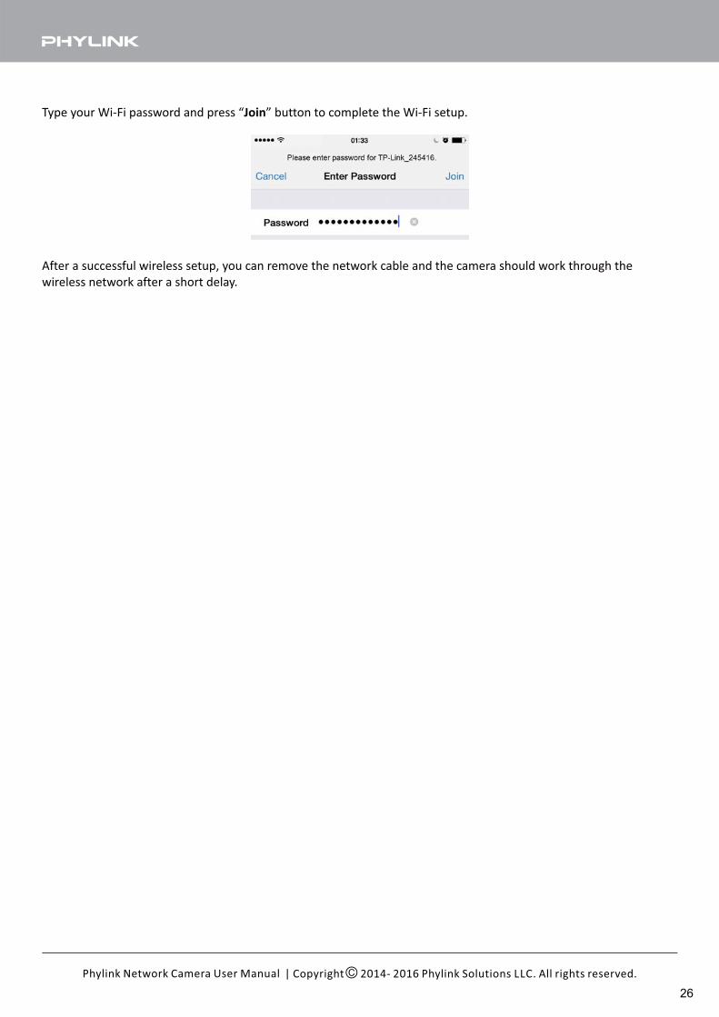
Type your Wi-Fi password and press “ ” button to complete the Wi-Fi setup.Join
After a successful wireless setup, you can remove the network cable and the camera should work through the
wireless network after a short delay.
26
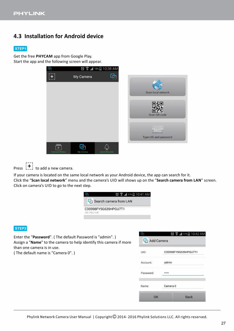
4.3 Installation for Android device
| Copyright 2014- 2016 Phylink Solutions LLC. All rights reserved.Phylink Network Camera User Manual
STEP1
Get the free app from Google Play.PHYCAM
Start the app and the following screen will appear.
STEP2
Enter the " ". ( The default Password is "admin". )Password
Assign a " " to the camera to help identify this camera if moreName
than one camera is in use.
( The default name is "Camera 0". )
Press to add a new camera.
If your camera is located on the same local network as your Android device, the app can search for it.
Click the “ ” menu and the camera’s UID will shows up on the " " screen.Scan local network Search camera from LAN
Click on camera’s UID to go to the next step.
27
| Copyright 2014- 2016 Phylink Solutions LLC. All rights reserved.Phylink Network Camera User Manual
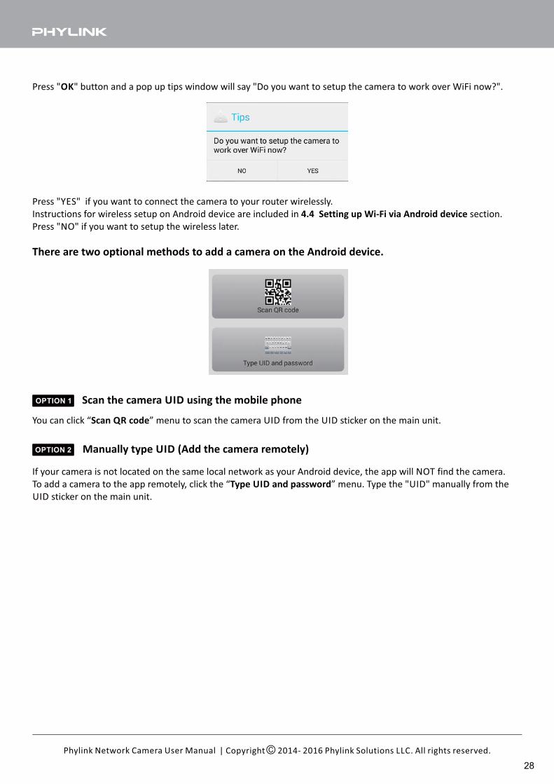
Press " " button and a pop up tips window will say "Do you want to setup the camera to work over WiFi now?".OK
Press "YES" if you want to connect the camera to your router wirelessly.
Instructions for wireless setup on Android device are included in section.4.4 Setting up Wi-Fi via Android device
Press "NO" if you want to setup the wireless later.
Scan the camera UID using the mobile phone
Manually type UID (Add the camera remotely)
There are two optional methods to add a camera on the Android device.
OPTION 1
You can click “ ” menu to scan the camera UID from the UID sticker on the main unit.Scan QR code
OPTION 2
If your camera is not located on the same local network as your Android device, the app will NOT find the camera.
To add a camera to the app remotely, click the “ ” menu. Type the "UID" manually from theType UID and password
UID sticker on the main unit.
28
| Copyright 2014- 2016 Phylink Solutions LLC. All rights reserved.Phylink Network Camera User Manual
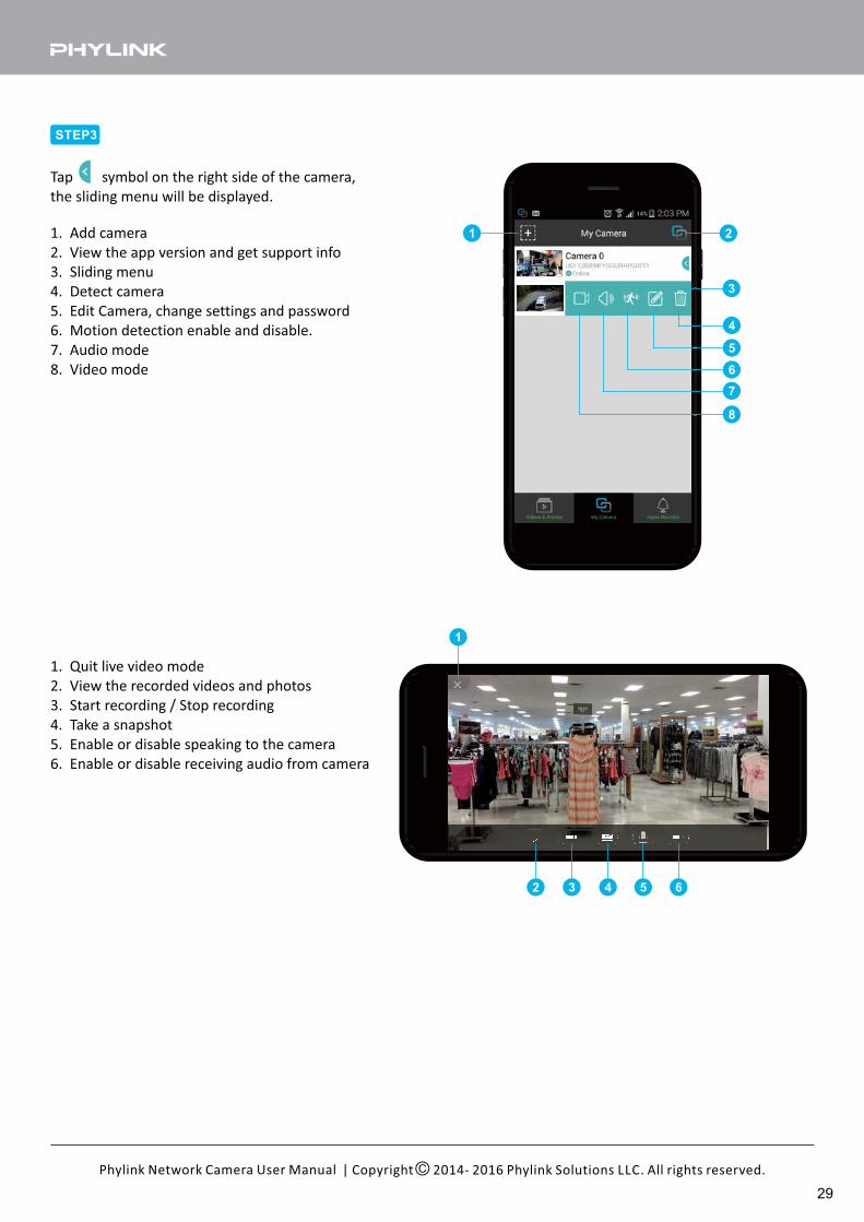
STEP3
1 2
3
4
5
6
7
8
Tap symbol on the right side of the camera,
the sliding menu will be displayed.
1. Add camera
2. View the app version and get support info
3. Sliding menu
4. Detect camera
5. Edit Camera, change settings and password
6. Motion detection enable and disable.
7. Audio mode
8. Video mode
1
2 3 4 5 6
1. Quit live video mode
2. View the recorded videos and photos
3. Start recording / Stop recording
4. Take a snapshot
5. Enable or disable speaking to the camera
6. Enable or disable receiving audio from camera
29
| Copyright 2014- 2016 Phylink Solutions LLC. All rights reserved.Phylink Network Camera User Manual
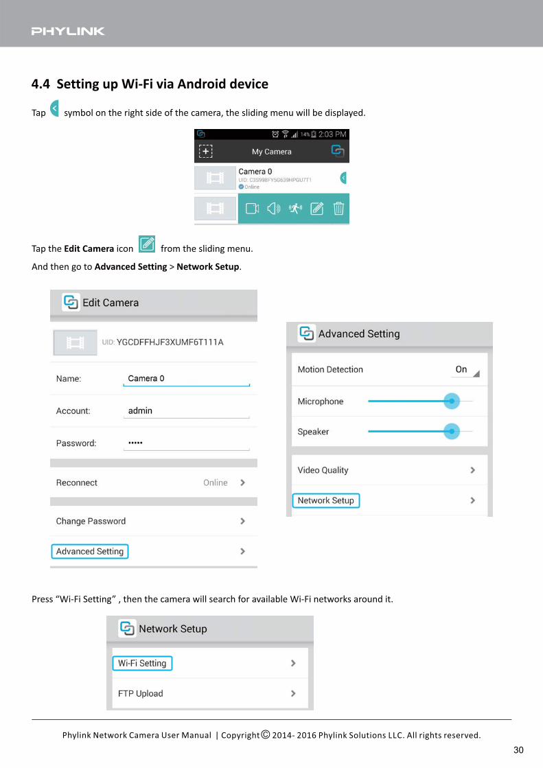
4.4 Setting up Wi-Fi via Android device
Tap symbol on the right side of the camera, the sliding menu will be displayed.
And then go to > .Advanced Setting Network Setup
Tap the icon from the sliding menu.Edit Camera
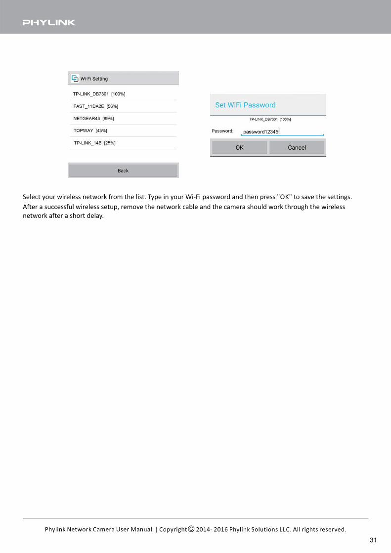
Press “Wi-Fi Setting” , then the camera will search for available Wi-Fi networks around it.
30
| Copyright 2014- 2016 Phylink Solutions LLC. All rights reserved.Phylink Network Camera User Manual
Select your wireless network from the list. Type in your Wi-Fi password and then press "OK" to save the settings.
After a successful wireless setup, remove the network cable and the camera should work through the wireless
network after a short delay.
31
| Copyright 2014- 2016 Phylink Solutions LLC. All rights reserved.Phylink Network Camera User Manual
4.5 Camera Setup on PC/Mac
4.5.1 Camera Live software installation
Phylink Camera Live is software which allows you to find and view your camera from the Internet easily.
It is also a tool that can search for your camera within your local network.
You can further configure or view your camera via the most popular web browsers such as FireFox, Internet Explorer,
Microsoft Edge (Windows 10), Chrome and Safari.
Phylink Camera Live is provided on the included CD, or you can download it from our technical support website, for
both the Windows and Mac OS.
http://phylink.com/downloads/index.htm#Software
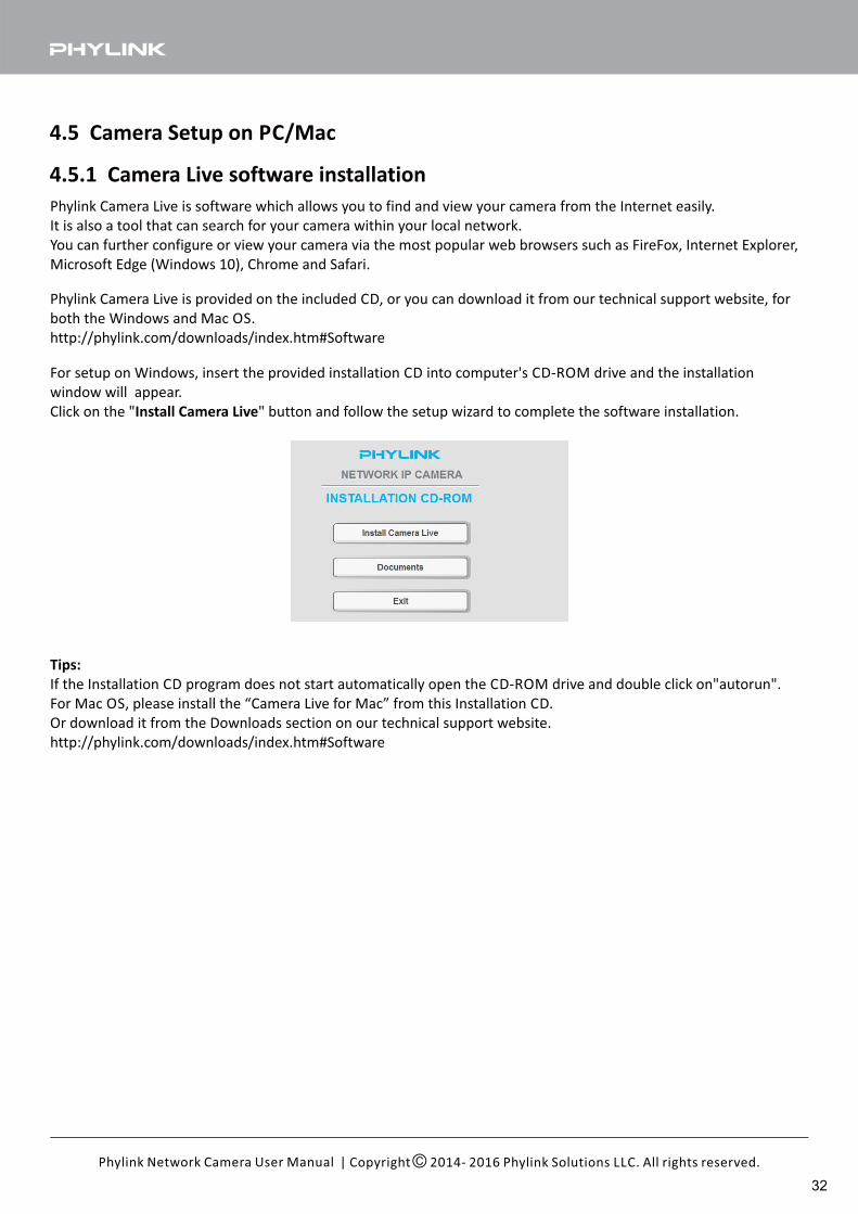
For setup on Windows, insert the provided installation CD into computer's CD-ROM drive and the installation
window will appear.
Click on the " " button and follow the setup wizard to complete the software installation.Install Camera Live
Tips:
If the Installation CD program does not start automatically open the CD-ROM drive and double click on"autorun".
For Mac OS, please install the “Camera Live for Mac” from this Installation CD.
Or download it from the Downloads section on our technical support website.
http://phylink.com/downloads/index.htm#Software
32
| Copyright 2014- 2016 Phylink Solutions LLC. All rights reserved.Phylink Network Camera User Manual
4.5.2 Accessing the camera using Camera Live (P2P method)
Phylink provides two accessing methods for different users: peer to peer and TCP/HTTP. The easier method is to use
the P2P option to access the camera.
When you access the camera using the Camera Live software on PC/Mac, the peer to peer connection will be
established automatically. P2P connection does not require the camera to get a public IP address and port or any
complicated settings such as IP address, port forwarding and DDNS. You only need to type the UID/Password and the
video can be displayed.
STEP1
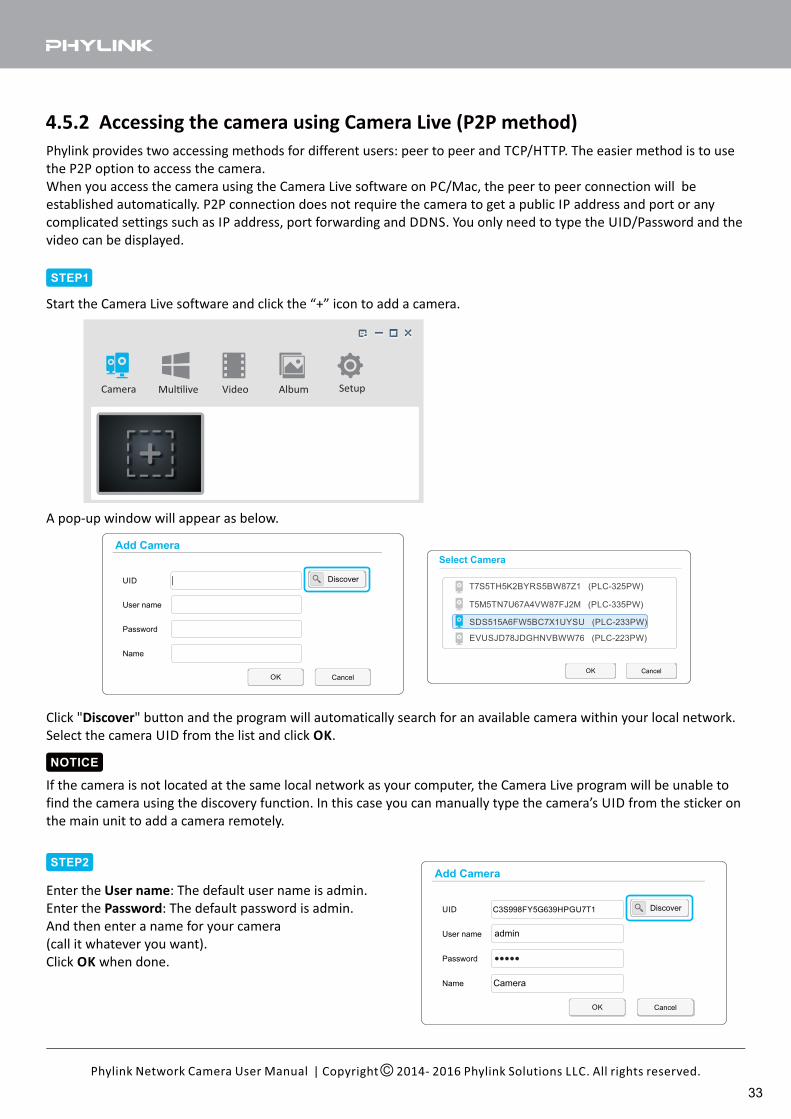
Start the Camera Live software and click the “+” icon to add a camera.
Select Camera
OK Cancel
EVUSJD78JDGHNVBWW76 (PLC-223PW)
T5M5TN7U67A4VW87FJ2M (PLC-335PW)
T7S5TH5K2BYRS5BW87Z1 (PLC-325PW)
SDS515A6FW5BC7X1UYSU (PLC-233PW)
A pop-up window will appear as below.
Click " " button and the program will automatically search for an available camera within your local network.Discover
Select the camera UID from the list and click .OK
STEP2
Enter the : The default user name is admin.User name
Enter the : The default password is admin.Password
And then enter a name for your camera
(call it whatever you want).
Click when done.OK
OK Cancel
Discover
User name
Password
UID
Add Camera
Name
OK Cancel
Discover
User name
Password
UID
Add Camera
Name
C3S998FY5G639HPGU7T1
Camera
admin
NOTICE
If the camera is not located at the same local network as your computer, the Camera Live program will be unable to
find the camera using the discovery function. In this case you can manually type the camera’s UID from the sticker on
the main unit to add a camera remotely.
Camera Mul�live Video Album Setup
33
| Copyright 2014- 2016 Phylink Solutions LLC. All rights reserved.Phylink Network Camera User Manual
Camera Multilive Video Album Setup
1920x1080 8FPS 1.3Mbps
Tip: How to Access the camera using Camera LiveTo learn more about Camera Live, please refer to " " in Support -
Technical Articles section from our technical support website.
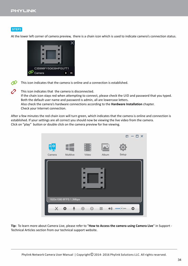
This icon indicates that the camera is online and a connection is established.
This icon indicates that the camera is disconnected.
If the chain icon stays red when attempting to connect, please check the UID and password that you typed.
Both the default user name and password is admin, all are lowercase letters.
Also check the camera’s hardware connections according to the chapter.Hardware Installation
Check your Internet connection.
At the lower left corner of camera preview, there is a chain icon which is used to indicate camera’s connection status.
STEP3
Camera
C3S998FY5G639HPGU7T1
After a few minutes the red chain icon will turn green, which indicates that the camera is online and connection is
established. If your settings are all correct you should now be viewing the live video from the camera.
Click on ”play” button or double click on the camera preview for live viewing.
34
| Copyright 2014- 2016 Phylink Solutions LLC. All rights reserved.Phylink Network Camera User Manual
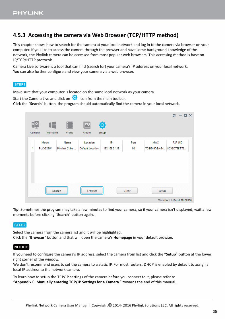
4.5.3 Accessing the camera via Web Browser (TCP/HTTP method)
This chapter shows how to search for the camera at your local network and log in to the camera via browser on your
computer. If you like to access the camera through the browser and have some background knowledge of the
network, the Phylink camera can be accessed from most popular web browsers. This accessing method is base on
IP/TCP/HTTP protocols.
Camera Live software is a tool that can find (search for) your camera’s IP address on your local network.
You can also further configure and view your camera via a web browser.
Start the Camera Live and click on icon from the main toolbar.
Click the " " button, the program should automatically find the camera in your local network.Search
Tip: Sometimes the program may take a few minutes to find your camera, so if your camera isn’t displayed, wait a few
moments before clicking “ ” button again.Search
Select the camera from the camera list and it will be highlighted.
Click the " " button and that will open the camera's in your default browser.Browser Homepage
NOTICE
If you need to configure the camera’s IP address, select the camera from list and click the “ ” button at the lowerSetup
right corner of the window.
We don't recommend users to set the camera to a static IP. For most routers, DHCP is enabled by default to assign a
local IP address to the network camera.
STEP1
STEP2
Make sure that your computer is located on the same local network as your camera.
To learn how to setup the TCP/IP settings of the camera before you connect to it, please refer to
“ ” towards the end of this manual.Appendix E: Manually entering TCP/IP Settings for a Camera
35
| Copyright 2014- 2016 Phylink Solutions LLC. All rights reserved.Phylink Network Camera User Manual
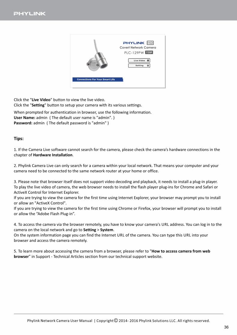
Click the " " button to view the live video.Live Video
Click the " " button to setup your camera with its various settings.Setting
When prompted for authentication in browser, use the following information.
User Name: admin ( The default user name is "admin". )
Password: admin ( The default password is "admin" )
Tips:
1. If the Camera Live software cannot search for the camera, please check the camera’s hardware connections in the
chapter of .Hardware Installation
2. Phylink Camera Live can only search for a camera within your local network. That means your computer and your
camera need to be connected to the same network router at your home or office.
3. Please note that browser itself does not support video decoding and playback, it needs to install a plug-in player.
To play the live video of camera, the web browser needs to install the flash player plug-ins for Chrome and Safari or
ActiveX Control for Internet Explorer.
If you are trying to view the camera for the first time using Internet Explorer, your browser may prompt you to install
or allow an "ActiveX Control".
If you are trying to view the camera for the first time using Chrome or Firefox, your browser will prompt you to install
or allow the “Adobe Flash Plug-in”.
4. To access the camera via the browser remotely, you have to know your camera's URL address. You can log in to the
camera on the local network and go to > .Setting System
On the system information page you can find the Internet URL of the camera. You can type this URL into your
browser and access the camera remotely.
5. To learn more about accessing the camera from a browser, please refer to "How to access camera from web
browser" in Support - Technical Articles section from our technical support website.
PLC-129PW
Covert Network Camera
720P
36
| Copyright 2014- 2016 Phylink Solutions LLC. All rights reserved.Phylink Network Camera User Manual
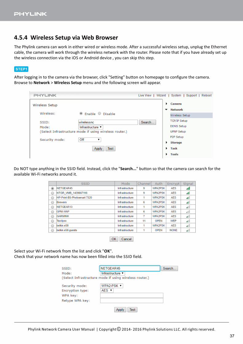
4.5.4 Wireless Setup via Web Browser
The Phylink camera can work in either wired or wireless mode. After a successful wireless setup, unplug the Ethernet
cable, the camera will work through the wireless network with the router. Please note that if you have already set up
the wireless connection via the iOS or Android device , you can skip this step.
After logging in to the camera via the browser, click "Setting" button on homepage to configure the camera.
Browse to > menu and the following screen will appear.Network Wireless Setup
Do NOT type anything in the SSID field. Instead, click the " " button so that the camera can search for theSearch...
available Wi-Fi networks around it.
Select your Wi-Fi network from the list and click " ".OK
Check that your network name has now been filled into the SSID field.
STEP1
37
| Copyright 2014- 2016 Phylink Solutions LLC. All rights reserved.Phylink Network Camera User Manual
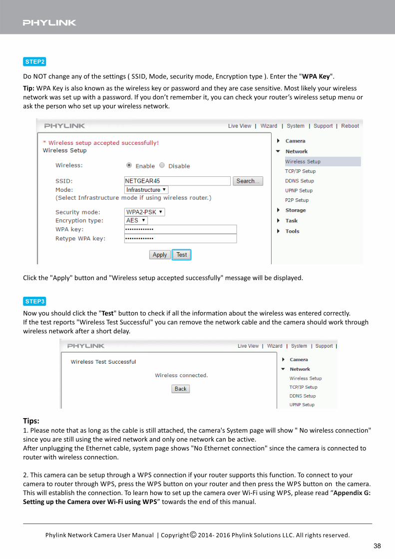
Click the "Apply" button and "Wireless setup accepted successfully" message will be displayed.
Now you should click the " " button to check if all the information about the wireless was entered correctly.Test
If the test reports "Wireless Test Successful" you can remove the network cable and the camera should work through
wireless network after a short delay.
Do NOT change any of the settings ( SSID, Mode, security mode, Encryption type ). Enter the " ".WPA Key
STEP2
Tip: WPA Key is also known as the wireless key or password and they are case sensitive. Most likely your wireless
network was set up with a password. If you don’t remember it, you can check your router’s wireless setup menu or
ask the person who set up your wireless network.
STEP3
Tips:1. Please note that as long as the cable is still attached, the camera's System page will show " No wireless connection"
since you are still using the wired network and only one network can be active.
After unplugging the Ethernet cable, system page shows "No Ethernet connection" since the camera is connected to
router with wireless connection.
2. This camera can be setup through a WPS connection if your router supports this function. To connect to your
camera to router through WPS, press the WPS button on your router and then press the WPS button on the camera.
This will establish the connection. To learn how to set up the camera over Wi-Fi using WPS, please read “Appendix G:
Setting up the Camera over Wi-Fi using WPS” towards the end of this manual.
38
5.0 Camera Settings
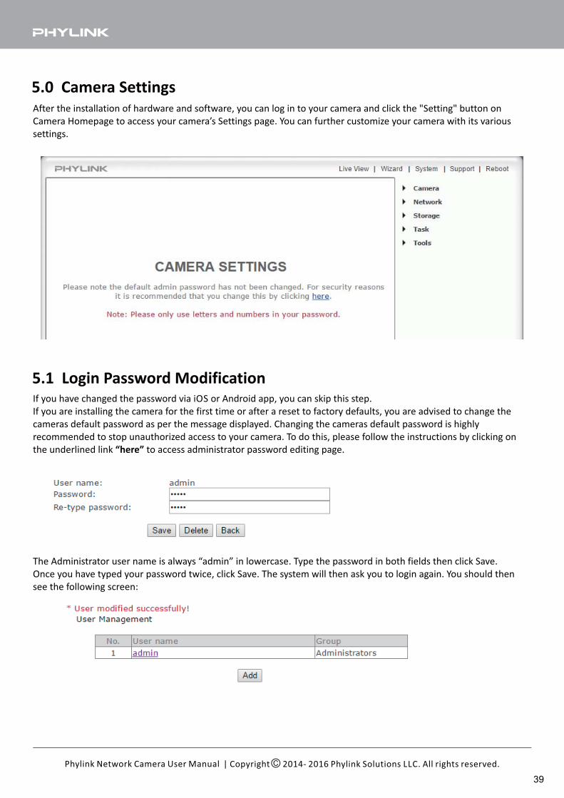
5.1 Login Password ModificationIf you have changed the password via iOS or Android app, you can skip this step.
If you are installing the camera for the first time or after a reset to factory defaults, you are advised to change the
cameras default password as per the message displayed. Changing the cameras default password is highly
recommended to stop unauthorized access to your camera. To do this, please follow the instructions by clicking on
the underlined link to access administrator password editing page.“here”
The Administrator user name is always “admin” in lowercase. Type the password in both fields then click Save.
Once you have typed your password twice, click Save. The system will then ask you to login again. You should then
see the following screen:
After the installation of hardware and software, you can log in to your camera and click the "Setting" button on
Camera Homepage to access your camera’s Settings page. You can further customize your camera with its various
settings.
| Copyright 2014- 2016 Phylink Solutions LLC. All rights reserved.Phylink Network Camera User Manual
39
1. Please note when changing the password please be sure to use alphanumeric characters only (letters and numbers,
up to 12 characters max) – do not use any special characters or add any empty spaces.
NOTICE
2. Keep this password safe. The only way to recover from a lost password is to reset the camera back to its default
settings, and this will wipe all other settings.
Tip: You can change the password under Tools > User Management menu later. Or you can change password via iOS
or Android app quickly.
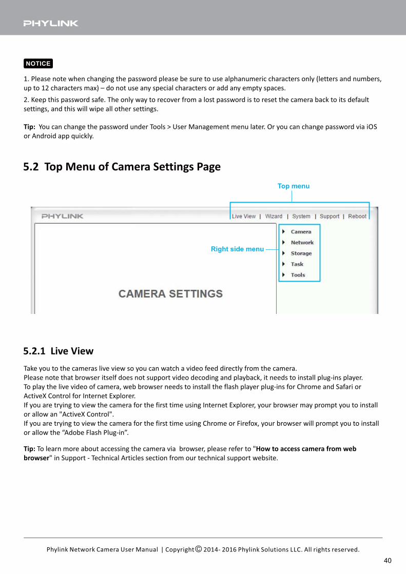
5.2 Top Menu of Camera Settings Page
Top menu
Right side menu
5.2.1 Live View
Take you to the cameras live view so you can watch a video feed directly from the camera.
Please note that browser itself does not support video decoding and playback, it needs to install plug-ins player.
To play the live video of camera, web browser needs to install the flash player plug-ins for Chrome and Safari or
ActiveX Control for Internet Explorer.
If you are trying to view the camera for the first time using Internet Explorer, your browser may prompt you to install
or allow an "ActiveX Control".
If you are trying to view the camera for the first time using Chrome or Firefox, your browser will prompt you to install
or allow the “Adobe Flash Plug-in”.
Tip: How to access camera from webTo learn more about accessing the camera via browser, please refer to "
browser" in Support - Technical Articles section from our technical support website.
| Copyright 2014- 2016 Phylink Solutions LLC. All rights reserved.Phylink Network Camera User Manual
40
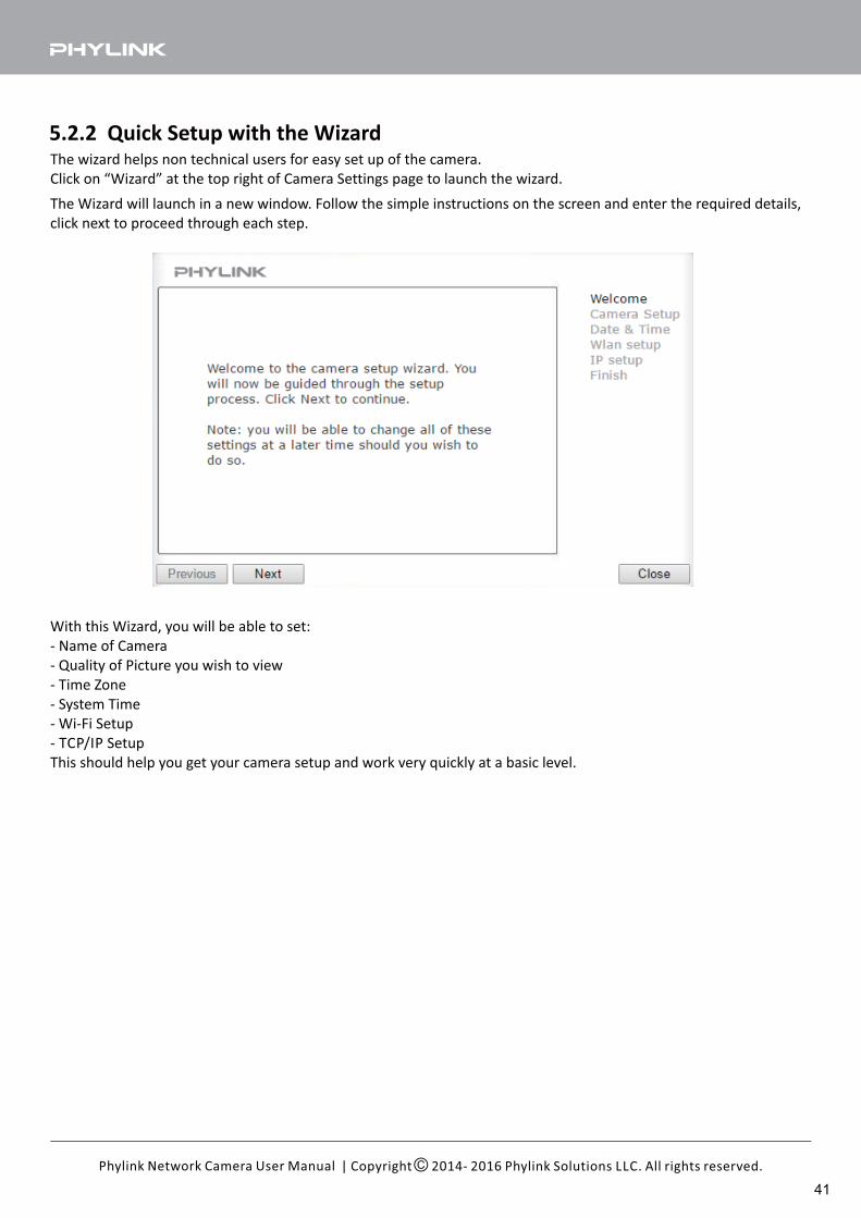
The wizard helps non technical users for easy set up of the camera.
Click on “Wizard” at the top right of Camera Settings page to launch the wizard.
5.2.2 Quick Setup with the Wizard
The Wizard will launch in a new window. Follow the simple instructions on the screen and enter the required details,
click next to proceed through each step.
With this Wizard, you will be able to set:
- Name of Camera
- Quality of Picture you wish to view
- Time Zone
- System Time
- Wi-Fi Setup
- TCP/IP Setup
This should help you get your camera setup and work very quickly at a basic level.
| Copyright 2014- 2016 Phylink Solutions LLC. All rights reserved.Phylink Network Camera User Manual
41
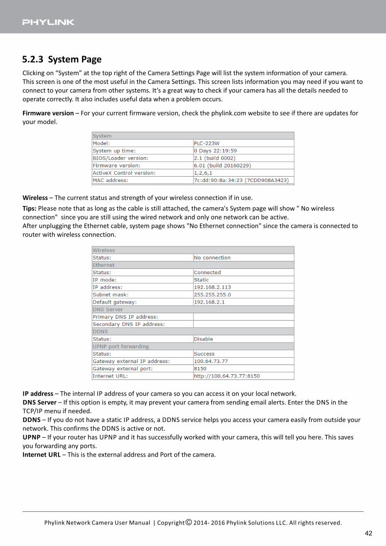
Clicking on “System” at the top right of the Camera Settings Page will list the system information of your camera.
This screen is one of the most useful in the Camera Settings. This screen lists information you may need if you want to
connect to your camera from other systems. It’s a great way to check if your camera has all the details needed to
operate correctly. It also includes useful data when a problem occurs.
5.2.3 System Page
| Copyright 2014- 2016 Phylink Solutions LLC. All rights reserved.Phylink Network Camera User Manual
Firmware version – For your current firmware version, check the phylink.com website to see if there are updates for
your model.
IP address – The internal IP address of your camera so you can access it on your local network.
DNS Server – If this option is empty, it may prevent your camera from sending email alerts. Enter the DNS in the
TCP/IP menu if needed.
DDNS – If you do not have a static IP address, a DDNS service helps you access your camera easily from outside your
network. This confirms the DDNS is active or not.
UPNP – If your router has UPNP and it has successfully worked with your camera, this will tell you here. This saves
you forwarding any ports.
Internet URL – This is the external address and Port of the camera.
Wireless – The current status and strength of your wireless connection if in use.
Tips: Please note that as long as the cable is still attached, the camera's System page will show " No wireless
connection" since you are still using the wired network and only one network can be active.
After unplugging the Ethernet cable, system page shows "No Ethernet connection" since the camera is connected to
router with wireless connection.
42
Click “Reboot” to restart the camera. Rebooting the camera will retain all the settings and configurations.
A reboot is normally necessary after inserting a microSD card into the camera or formatting the microSD card.
5.2.4 Reboot
| Copyright 2014- 2016 Phylink Solutions LLC. All rights reserved.Phylink Network Camera User Manual
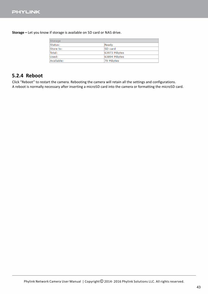
Storage – Let you know if storage is available on SD card or NAS drive.
43
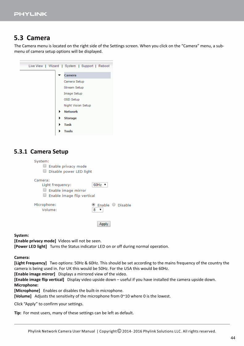
5.3.1 Camera Setup
The Camera menu is located on the right side of the Settings screen. When you click on the “Camera” menu, a sub-
menu of camera setup options will be displayed.
5.3 Camera
Tip: For most users, many of these settings can be left as default.
System:
[Enable privacy mode] Videos will not be seen.
[Power LED light] Turns the Status indicator LED on or off during normal operation.
Camera:
[Light Frequency] Two options: 50Hz & 60Hz. This should be set according to the mains frequency of the country the
camera is being used in. For UK this would be 50Hz. For the USA this would be 60Hz.
[Enable image mirror] Displays a mirrored view of the video.
[Enable image flip vertical] Display video upside down – useful if you have installed the camera upside down.
Microphone:
[Microphone] Enables or disables the built-in microphone.
[Volume] Adjusts the sensitivity of the microphone from 0~10 where 0 is the lowest.
Click “Apply” to confirm your settings.
| Copyright 2014- 2016 Phylink Solutions LLC. All rights reserved.Phylink Network Camera User Manual
44
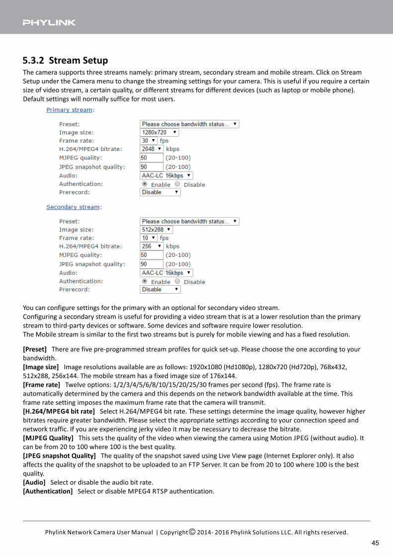
5.3.2 Stream SetupThe camera supports three streams namely: primary stream, secondary stream and mobile stream. Click on Stream
Setup under the Camera menu to change the streaming settings for your camera. This is useful if you require a certain
size of video stream, a certain quality, or different streams for different devices (such as laptop or mobile phone).
Default settings will normally suffice for most users.
You can configure settings for the primary with an optional for secondary video stream.
Configuring a secondary stream is useful for providing a video stream that is at a lower resolution than the primary
stream to third-party devices or software. Some devices and software require lower resolution.
The Mobile stream is similar to the first two streams but is purely for mobile viewing and has a fixed resolution.
[Preset] There are five pre-programmed stream profiles for quick set-up. Please choose the one according to your
bandwidth.
[Image size] Image resolutions available are as follows: 1920x1080 (Hd1080p), 1280x720 (Hd720p), 768x432,
512x288, 256x144. The mobile stream has a fixed image size of 176x144.
[Frame rate] Twelve options: 1/2/3/4/5/6/8/10/15/20/25/30 frames per second (fps). The frame rate is
automatically determined by the camera and this depends on the network bandwidth available at the time. This
frame rate setting imposes the maximum frame rate that the camera will transmit.
[H.264/MPEG4 bit rate] Select H.264/MPEG4 bit rate. These settings determine the image quality, however higher
bitrates require greater bandwidth. Please select the appropriate settings according to your connection speed and
network traffic. If you are experiencing jerky video it may be necessary to decrease the bitrate.
[MJPEG Quality] This sets the quality of the video when viewing the camera using Motion JPEG (without audio). It
can be from 20 to 100 where 100 is the best quality.
[JPEG snapshot Quality] The quality of the snapshot saved using Live View page (Internet Explorer only). It also
affects the quality of the snapshot to be uploaded to an FTP Server. It can be from 20 to 100 where 100 is the best
quality.
[Audio] Select or disable the audio bit rate.
[Authentication] Select or disable MPEG4 RTSP authentication.
| Copyright 2014- 2016 Phylink Solutions LLC. All rights reserved.Phylink Network Camera User Manual
45
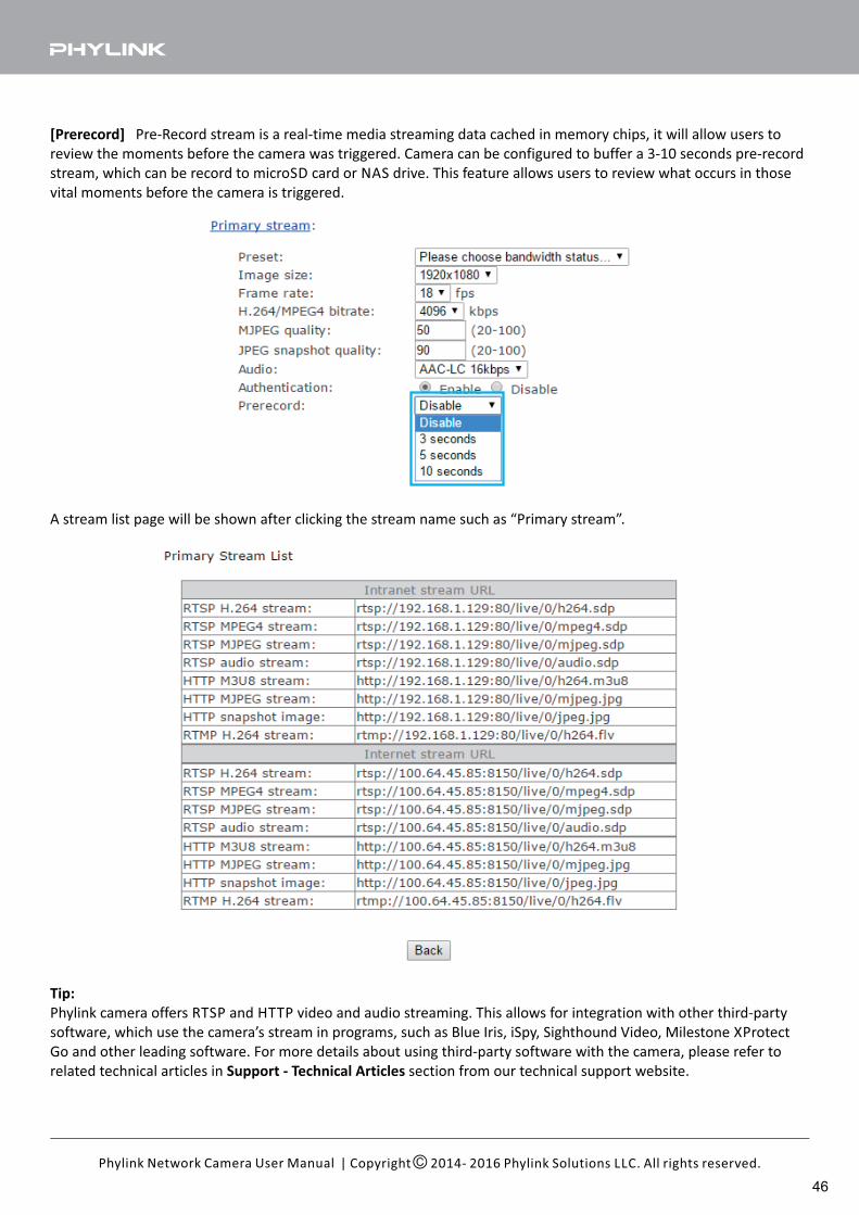
A stream list page will be shown after clicking the stream name such as “Primary stream”.
Tip:
Phylink camera offers RTSP and HTTP video and audio streaming. This allows for integration with other third-party
software, which use the camera’s stream in programs, such as Blue Iris, iSpy, Sighthound Video, Milestone XProtect
Go and other leading software. For more details about using third-party software with the camera, please refer to
related technical articles in section from our technical support website.Support - Technical Articles
| Copyright 2014- 2016 Phylink Solutions LLC. All rights reserved.Phylink Network Camera User Manual
[Prerecord] Pre-Record stream is a real-time media streaming data cached in memory chips, it will allow users to
review the moments before the camera was triggered. Camera can be configured to buffer a 3-10 seconds pre-record
stream, which can be record to microSD card or NAS drive. This feature allows users to review what occurs in those
vital moments before the camera is triggered.
46
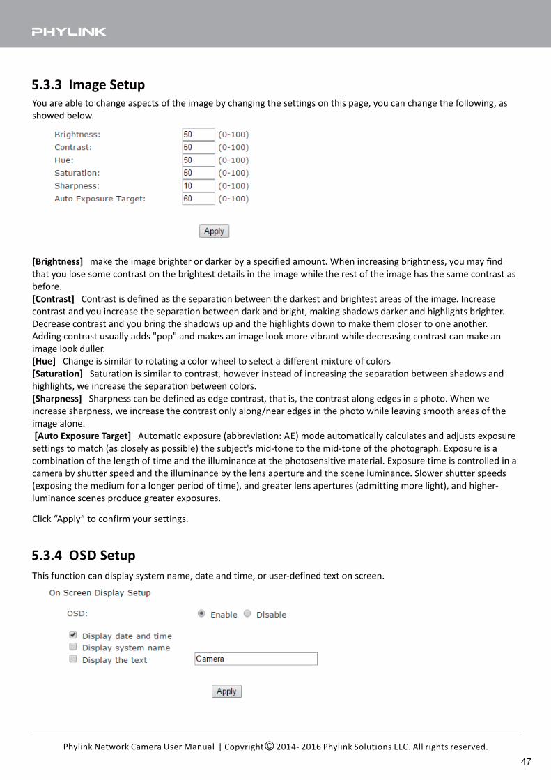
You are able to change aspects of the image by changing the settings on this page, you can change the following, as
showed below.
[Brightness] make the image brighter or darker by a specified amount. When increasing brightness, you may find
that you lose some contrast on the brightest details in the image while the rest of the image has the same contrast as
before.
[Contrast] Contrast is defined as the separation between the darkest and brightest areas of the image. Increase
contrast and you increase the separation between dark and bright, making shadows darker and highlights brighter.
Decrease contrast and you bring the shadows up and the highlights down to make them closer to one another.
Adding contrast usually adds "pop" and makes an image look more vibrant while decreasing contrast can make an
image look duller.
[Hue] Change is similar to rotating a color wheel to select a different mixture of colors
[Saturation] Saturation is similar to contrast, however instead of increasing the separation between shadows and
highlights, we increase the separation between colors.
[Sharpness] Sharpness can be defined as edge contrast, that is, the contrast along edges in a photo. When we
increase sharpness, we increase the contrast only along/near edges in the photo while leaving smooth areas of the
image alone.
Automatic exposure (abbreviation: AE) mode automatically calculates and adjusts exposure[Auto Exposure Target]
settings to match (as closely as possible) the subject's mid-tone to the mid-tone of the photograph. Exposure is a
combination of the length of time and the illuminance at the photosensitive material. Exposure time is controlled in a
camera by shutter speed and the illuminance by the lens aperture and the scene luminance. Slower shutter speeds
(exposing the medium for a longer period of time), and greater lens apertures (admitting more light), and higher-
luminance scenes produce greater exposures.
5.3.3 Image Setup
5.3.4 OSD Setup
Click “Apply” to confirm your settings.
This function can display system name, date and time, or user-defined text on screen.
| Copyright 2014- 2016 Phylink Solutions LLC. All rights reserved.Phylink Network Camera User Manual
47
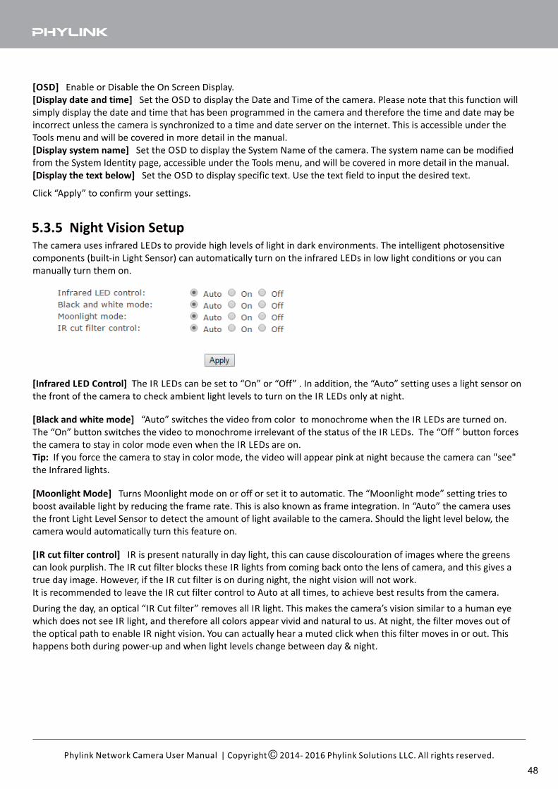
[OSD] Enable or Disable the On Screen Display.
[Display date and time] Set the OSD to display the Date and Time of the camera. Please note that this function will
simply display the date and time that has been programmed in the camera and therefore the time and date may be
incorrect unless the camera is synchronized to a time and date server on the internet. This is accessible under the
Tools menu and will be covered in more detail in the manual.
[Display system name] Set the OSD to display the System Name of the camera. The system name can be modified
from the System Identity page, accessible under the Tools menu, and will be covered in more detail in the manual.
[Display the text below] Set the OSD to display specific text. Use the text field to input the desired text.
Click “Apply” to confirm your settings.
5.3.5 Night Vision SetupThe camera uses infrared LEDs to provide high levels of light in dark environments. The intelligent photosensitive
components (built-in Light Sensor) can automatically turn on the infrared LEDs in low light conditions or you can
manually turn them on.
[IR cut filter control] IR is present naturally in day light, this can cause discolouration of images where the greens
can look purplish. The IR cut filter blocks these IR lights from coming back onto the lens of camera, and this gives a
true day image. However, if the IR cut filter is on during night, the night vision will not work.
It is recommended to leave the IR cut filter control to Auto at all times, to achieve best results from the camera.
| Copyright 2014- 2016 Phylink Solutions LLC. All rights reserved.Phylink Network Camera User Manual
[Infrared LED Control] The IR LEDs can be set to “On” or “Off” . In addition, the “Auto” setting uses a light sensor on
the front of the camera to check ambient light levels to turn on the IR LEDs only at night.
[Black and white mode] “Auto” switches the video from color to monochrome when the IR LEDs are turned on.
The “On” button switches the video to monochrome irrelevant of the status of the IR LEDs. The “Off ” button forces
the camera to stay in color mode even when the IR LEDs are on.
Tip: If you force the camera to stay in color mode, the video will appear pink at night because the camera can "see"
the Infrared lights.
[Moonlight Mode] Turns Moonlight mode on or off or set it to automatic. The “Moonlight mode” setting tries to
boost available light by reducing the frame rate. This is also known as frame integration. In “Auto” the camera uses
the front Light Level Sensor to detect the amount of light available to the camera. Should the light level below, the
camera would automatically turn this feature on.
During the day, an optical “IR Cut filter” removes all IR light. This makes the camera’s vision similar to a human eye
which does not see IR light, and therefore all colors appear vivid and natural to us. At night, the filter moves out of
the optical path to enable IR night vision. You can actually hear a muted click when this filter moves in or out. This
happens both during power-up and when light levels change between day & night.
48
| Copyright 2014- 2016 Phylink Solutions LLC. All rights reserved.Phylink Network Camera User Manual
3. For best IR night vision on outdoor cameras please refer to - chapter.Hardware Installation Adjust the Sunshade
Clean lens cover glass also helps extend the range and reduces fogginess.
Tips:
1. The factory default settings is “Auto” and this is recommended.
2. If you are using the camera to look through a window, you may want to experiment with the IR filter in the
automatic position even though IR LEDs are set off. Combined with automatic moonlight and automatic black &
white mode this makes the best use of available street lighting.
49
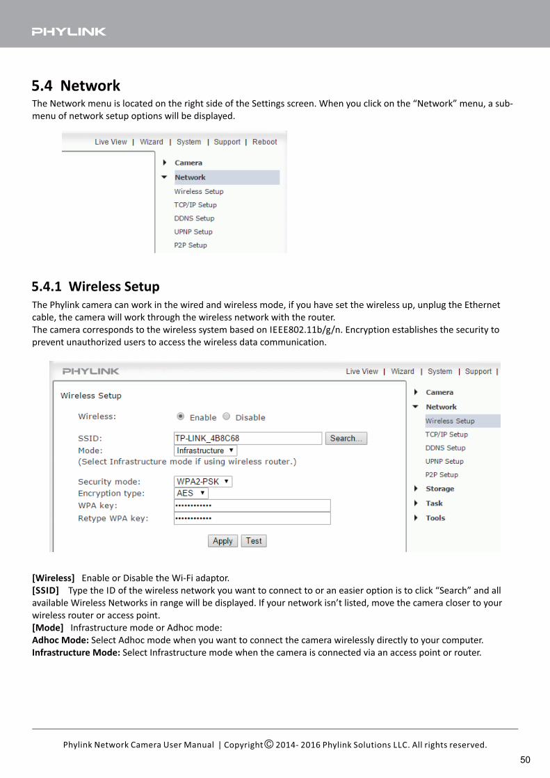
The Network menu is located on the right side of the Settings screen. When you click on the “Network” menu, a sub-
menu of network setup options will be displayed.
5.4 Network
5.4.1 Wireless Setup
The Phylink camera can work in the wired and wireless mode, if you have set the wireless up, unplug the Ethernet
cable, the camera will work through the wireless network with the router.
The camera corresponds to the wireless system based on IEEE802.11b/g/n. Encryption establishes the security to
prevent unauthorized users to access the wireless data communication.
[Wireless] Enable or Disable the Wi-Fi adaptor.
[SSID] Type the ID of the wireless network you want to connect to or an easier option is to click “Search” and all
available Wireless Networks in range will be displayed. If your network isn’t listed, move the camera closer to your
wireless router or access point.
[Mode] Infrastructure mode or Adhoc mode:
Adhoc Mode: Select Adhoc mode when you want to connect the camera wirelessly directly to your computer.
Infrastructure Mode: Select Infrastructure mode when the camera is connected via an access point or router.
| Copyright 2014- 2016 Phylink Solutions LLC. All rights reserved.Phylink Network Camera User Manual
50
[Security mode] Select the type of security mode that your wireless network is using. None (i.e. off), WEP64,
WEP128, WPA-PSK or WPA2-PSK.
Whichever you are using, you will need to enter the settings to connect to your router. Each mode has default
settings, which should suit most installations.
[Encryption type] Select either TKIP or AES for your default encryption setting.
[WPA key] Type 8-63 characters as password.
[Re-type WPA key] Re-confirm the password.
Tip: 4.5.4 Wireless Setup via Web BrowserTo learn more about setting up wireless via browser, please refer to " "
chapter in this manual.
| Copyright 2014- 2016 Phylink Solutions LLC. All rights reserved.Phylink Network Camera User Manual
51
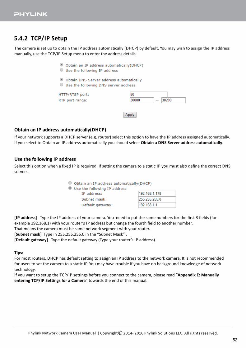
5.4.2 TCP/IP Setup
The camera is set up to obtain the IP address automatically (DHCP) by default. You may wish to assign the IP address
manually, use the TCP/IP Setup menu to enter the address details.
If your network supports a DHCP server (e.g. router) select this option to have the IP address assigned automatically.
If you select to Obtain an IP address automatically you should select .Obtain a DNS Server address automatically
Obtain an IP address automatically(DHCP)
Select this option when a fixed IP is required. If setting the camera to a static IP you must also define the correct DNS
servers.
Use the following IP address
Tips:
For most routers, DHCP has default setting to assign an IP address to the network camera. It is not recommended
for users to set the camera to a static IP. You may have trouble if you have no background knowledge of network
technology.
If you want to setup the TCP/IP settings before you connect to the camera, please read “Appendix E: Manually
entering TCP/IP Settings for a Camera” towards the end of this manual.
[IP address] Type the IP address of your camera. You need to put the same numbers for the first 3 fields (for
example 192.168.1) with your router’s IP address but change the fourth field to another number.
That means the camera must be same network segment with your router.
[Subnet mask] Type in 255.255.255.0 in the “Subnet Mask” .
[Default gateway] Type the default gateway (Type your router’s IP address).
| Copyright 2014- 2016 Phylink Solutions LLC. All rights reserved.Phylink Network Camera User Manual
52
[HTTP port number] The default HTTP port number is 80, it is also be used as RTSP port.
[RTP port range] Leave the default setting or enter the RTP port as below: The RTP port range should start at 30000
for your first camera. For all additional cameras the start of the range increase by 2, for example your 2nd camera
would have a starting RTP port of 30002, the 3rd camera would have 30004, 4th camera at 30006 etc.
| Copyright 2014- 2016 Phylink Solutions LLC. All rights reserved.Phylink Network Camera User Manual
Obtain DNS Server address automatically
Use the following DNS server address
If your network supports a DHCP server (e.g. router) select this option to have the DNS Server address assigned
automatically.
Use this option when a fixed DNS is required.
53
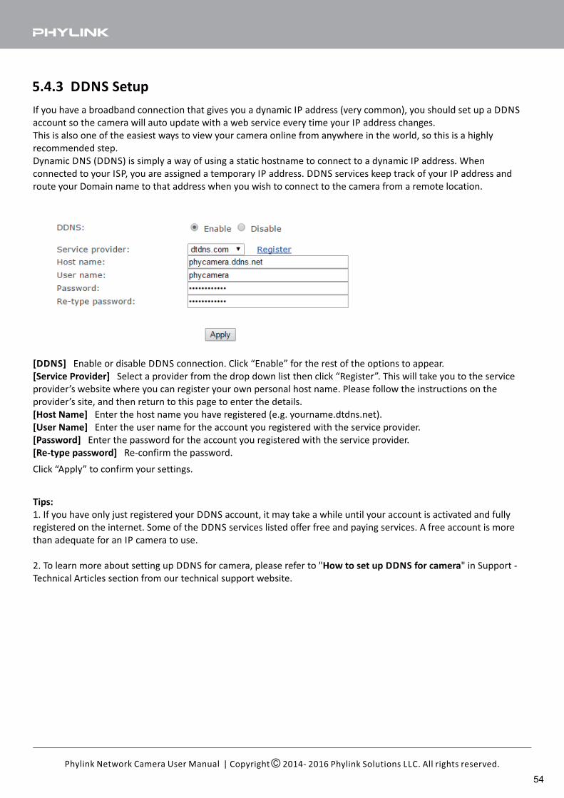
5.4.3 DDNS Setup
If you have a broadband connection that gives you a dynamic IP address (very common), you should set up a DDNS
account so the camera will auto update with a web service every time your IP address changes.
This is also one of the easiest ways to view your camera online from anywhere in the world, so this is a highly
recommended step.
Dynamic DNS (DDNS) is simply a way of using a static hostname to connect to a dynamic IP address. When
connected to your ISP, you are assigned a temporary IP address. DDNS services keep track of your IP address and
route your Domain name to that address when you wish to connect to the camera from a remote location.
[DDNS] Enable or disable DDNS connection. Click “Enable” for the rest of the options to appear.
[Service Provider] Select a provider from the drop down list then click “Register”. This will take you to the service
provider’s website where you can register your own personal host name. Please follow the instructions on the
provider’s site, and then return to this page to enter the details.
[Host Name] Enter the host name you have registered (e.g. yourname.dtdns.net).
[User Name] Enter the user name for the account you registered with the service provider.
[Password] Enter the password for the account you registered with the service provider.
[Re-type password] Re-confirm the password.
Click “Apply” to confirm your settings.
Tips:
1. If you have only just registered your DDNS account, it may take a while until your account is activated and fully
registered on the internet. Some of the DDNS services listed offer free and paying services. A free account is more
than adequate for an IP camera to use.
2. To learn more about setting up DDNS for camera, please refer to " " in Support -How to set up DDNS for camera
Technical Articles section from our technical support website.
| Copyright 2014- 2016 Phylink Solutions LLC. All rights reserved.Phylink Network Camera User Manual
54
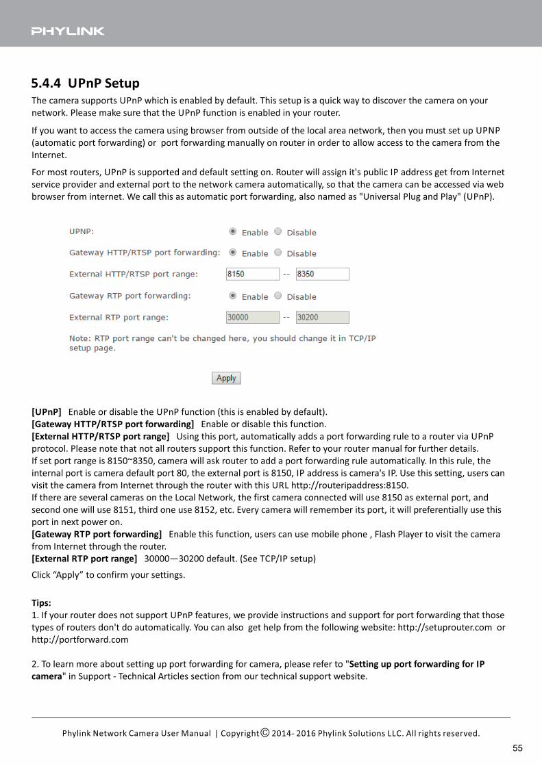
5.4.4 UPnP SetupThe camera supports UPnP which is enabled by default. This setup is a quick way to discover the camera on your
network. Please make sure that the UPnP function is enabled in your router.
If you want to access the camera using browser from outside of the local area network, then you must set up UPNP
(automatic port forwarding) or port forwarding manually on router in order to allow access to the camera from the
Internet.
For most routers, UPnP is supported and default setting on. Router will assign it's public IP address get from Internet
service provider and external port to the network camera automatically, so that the camera can be accessed via web
browser from internet. We call this as automatic port forwarding, also named as "Universal Plug and Play" (UPnP).
[UPnP] Enable or disable the UPnP function (this is enabled by default).
[Gateway HTTP/RTSP port forwarding] Enable or disable this function.
[External HTTP/RTSP port range] Using this port, automatically adds a port forwarding rule to a router via UPnP
protocol. Please note that not all routers support this function. Refer to your router manual for further details.
If set port range is 8150~8350, camera will ask router to add a port forwarding rule automatically. In this rule, the
internal port is camera default port 80, the external port is 8150, IP address is camera's IP. Use this setting, users can
visit the camera from Internet through the router with this URL http://routeripaddress:8150.
If there are several cameras on the Local Network, the first camera connected will use 8150 as external port, and
second one will use 8151, third one use 8152, etc. Every camera will remember its port, it will preferentially use this
port in next power on.
[Gateway RTP port forwarding] Enable this function, users can use mobile phone , Flash Player to visit the camera
from Internet through the router.
[External RTP port range] 30000—30200 default. (See TCP/IP setup)
Click “Apply” to confirm your settings.
Tips:
1. If your router does not support UPnP features, we provide instructions and support for port forwarding that those
types of routers don't do automatically. You can also get help from the following website: http://setuprouter.com or
http://portforward.com
2. To learn more about setting up port forwarding for camera, please refer to "Setting up port forwarding for IP
camera" in Support - Technical Articles section from our technical support website.
| Copyright 2014- 2016 Phylink Solutions LLC. All rights reserved.Phylink Network Camera User Manual
55
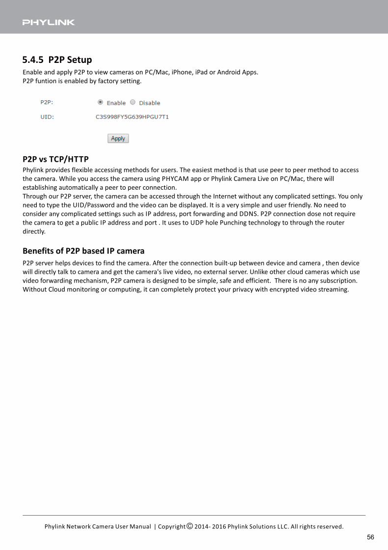
5.4.5 P2P SetupEnable and apply P2P to view cameras on PC/Mac, iPhone, iPad or Android Apps.
P2P funtion is enabled by factory setting.
P2P server helps devices to find the camera. After the connection built-up between device and camera , then device
will directly talk to camera and get the camera's live video, no external server. Unlike other cloud cameras which use
video forwarding mechanism, P2P camera is designed to be simple, safe and efficient. There is no any subscription.
Without Cloud monitoring or computing, it can completely protect your privacy with encrypted video streaming.
Phylink provides flexible accessing methods for users. The easiest method is that use peer to peer method to access
the camera. While you access the camera using PHYCAM app or Phylink Camera Live on PC/Mac, there will
establishing automatically a peer to peer connection.
Through our P2P server, the camera can be accessed through the Internet without any complicated settings. You only
need to type the UID/Password and the video can be displayed. It is a very simple and user friendly. No need to
consider any complicated settings such as IP address, port forwarding and DDNS. P2P connection dose not require
the camera to get a public IP address and port . It uses to UDP hole Punching technology to through the router
directly.
P2P vs TCP/HTTP
Benefits of P2P based IP camera
| Copyright 2014- 2016 Phylink Solutions LLC. All rights reserved.Phylink Network Camera User Manual
56
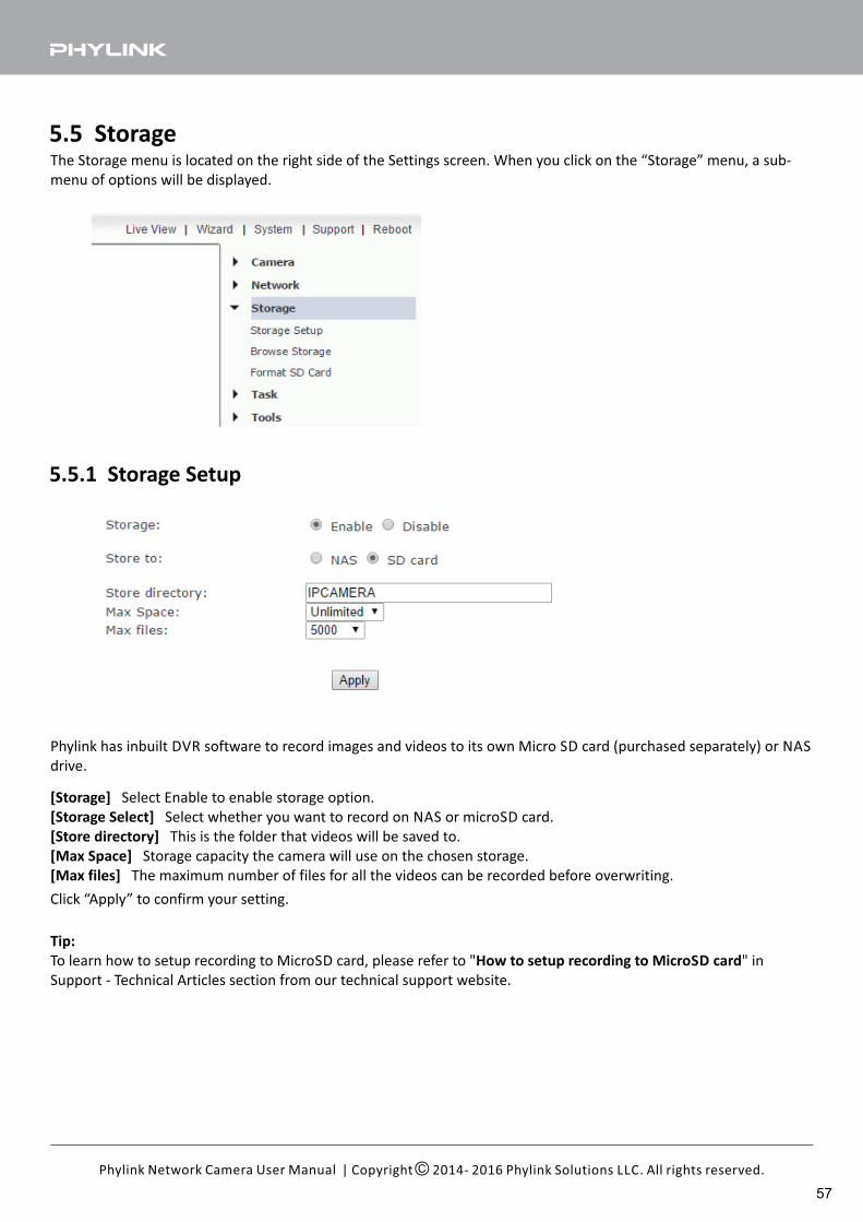
5.5 Storage
5.5.1 Storage Setup
The Storage menu is located on the right side of the Settings screen. When you click on the “Storage” menu, a sub-
menu of options will be displayed.
[Storage] Select Enable to enable storage option.
[Storage Select] Select whether you want to record on NAS or microSD card.
[Store directory] This is the folder that videos will be saved to.
[Max Space] Storage capacity the camera will use on the chosen storage.
[Max files] The maximum number of files for all the videos can be recorded before overwriting.
Click “Apply” to confirm your setting.
Phylink has inbuilt DVR software to record images and videos to its own Micro SD card (purchased separately) or NAS
drive.
Tip:
To learn how to setup recording to MicroSD card, please refer to " " inHow to setup recording to MicroSD card
Support - Technical Articles section from our technical support website.
| Copyright 2014- 2016 Phylink Solutions LLC. All rights reserved.Phylink Network Camera User Manual
57
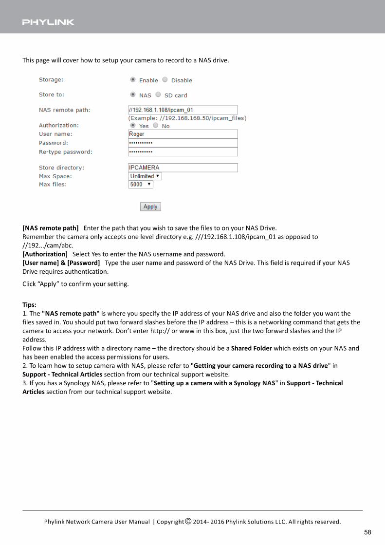
This page will cover how to setup your camera to record to a NAS drive.
[NAS remote path] Enter the path that you wish to save the files to on your NAS Drive.
Remember the camera only accepts one level directory e.g. ///192.168.1.108/ipcam_01 as opposed to
//192.../cam/abc.
[Authorization] Select Yes to enter the NAS username and password.
[User name] & [Password] Type the user name and password of the NAS Drive. This field is required if your NAS
Drive requires authentication.
Click “Apply” to confirm your setting.
Tips:
1. The is where you specify the IP address of your NAS drive and also the folder you want the"NAS remote path"
files saved in. You should put two forward slashes before the IP address – this is a networking command that gets the
camera to access your network. Don’t enter http:// or www in this box, just the two forward slashes and the IP
address.
Follow this IP address with a directory name – the directory should be a which exists on your NAS andShared Folder
has been enabled the access permissions for users.
2. To learn how to setup camera with NAS, please refer to " " inGetting your camera recording to a NAS drive
Support - Technical Articles section from our technical support website.
3. If you has a Synology NAS, please refer to " " inSetting up a camera with a Synology NAS Support - Technical
Articles section from our technical support website.
| Copyright 2014- 2016 Phylink Solutions LLC. All rights reserved.Phylink Network Camera User Manual
58
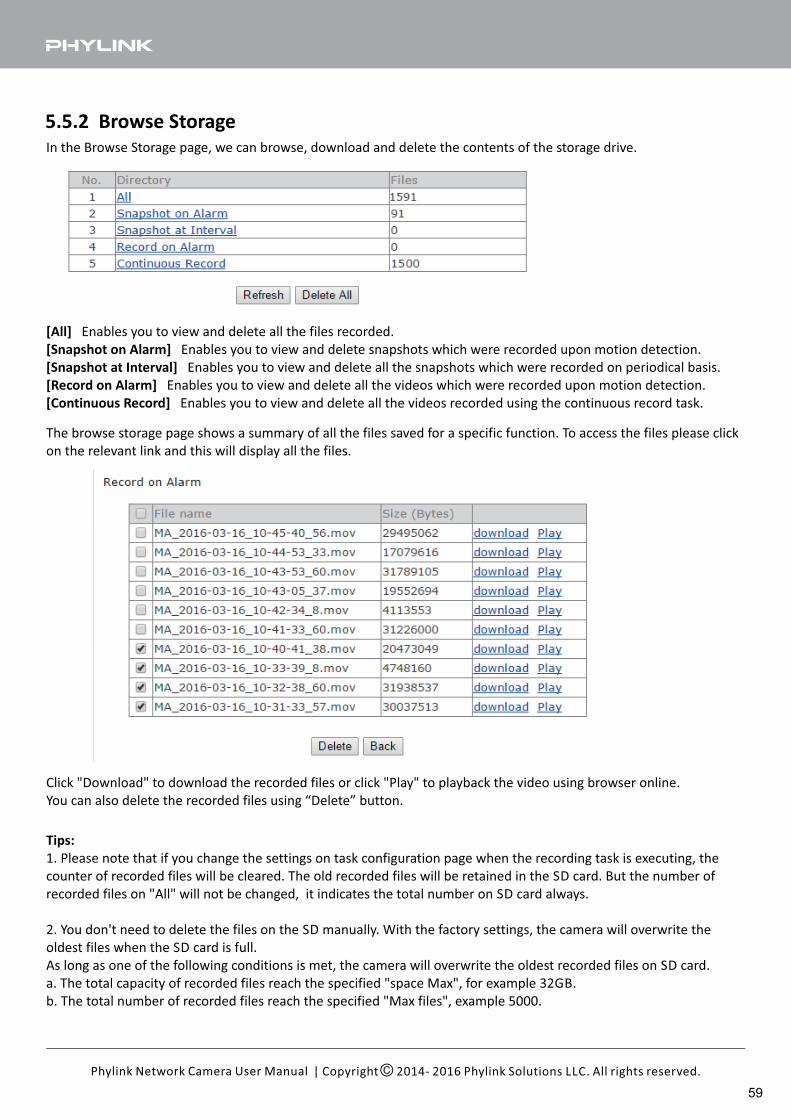
5.5.2 Browse StorageIn the Browse Storage page, we can browse, download and delete the contents of the storage drive.
[All] Enables you to view and delete all the files recorded.
[Snapshot on Alarm] Enables you to view and delete snapshots which were recorded upon motion detection.
[Snapshot at Interval] Enables you to view and delete all the snapshots which were recorded on periodical basis.
[Record on Alarm] Enables you to view and delete all the videos which were recorded upon motion detection.
[Continuous Record] Enables you to view and delete all the videos recorded using the continuous record task.
Click "Download" to download the recorded files or click "Play" to playback the video using browser online.
You can also delete the recorded files using “Delete” button.
The browse storage page shows a summary of all the files saved for a specific function. To access the files please click
on the relevant link and this will display all the files.
Tips:
1. Please note that if you change the settings on task configuration page when the recording task is executing, the
counter of recorded files will be cleared. The old recorded files will be retained in the SD card. But the number of
recorded files on "All" will not be changed, it indicates the total number on SD card always.
2. You don't need to delete the files on the SD manually. With the factory settings, the camera will overwrite the
oldest files when the SD card is full.
As long as one of the following conditions is met, the camera will overwrite the oldest recorded files on SD card.
a. The total capacity of recorded files reach the specified "space Max", for example 32GB.
b. The total number of recorded files reach the specified "Max files", example 5000.
| Copyright 2014- 2016 Phylink Solutions LLC. All rights reserved.Phylink Network Camera User Manual
59
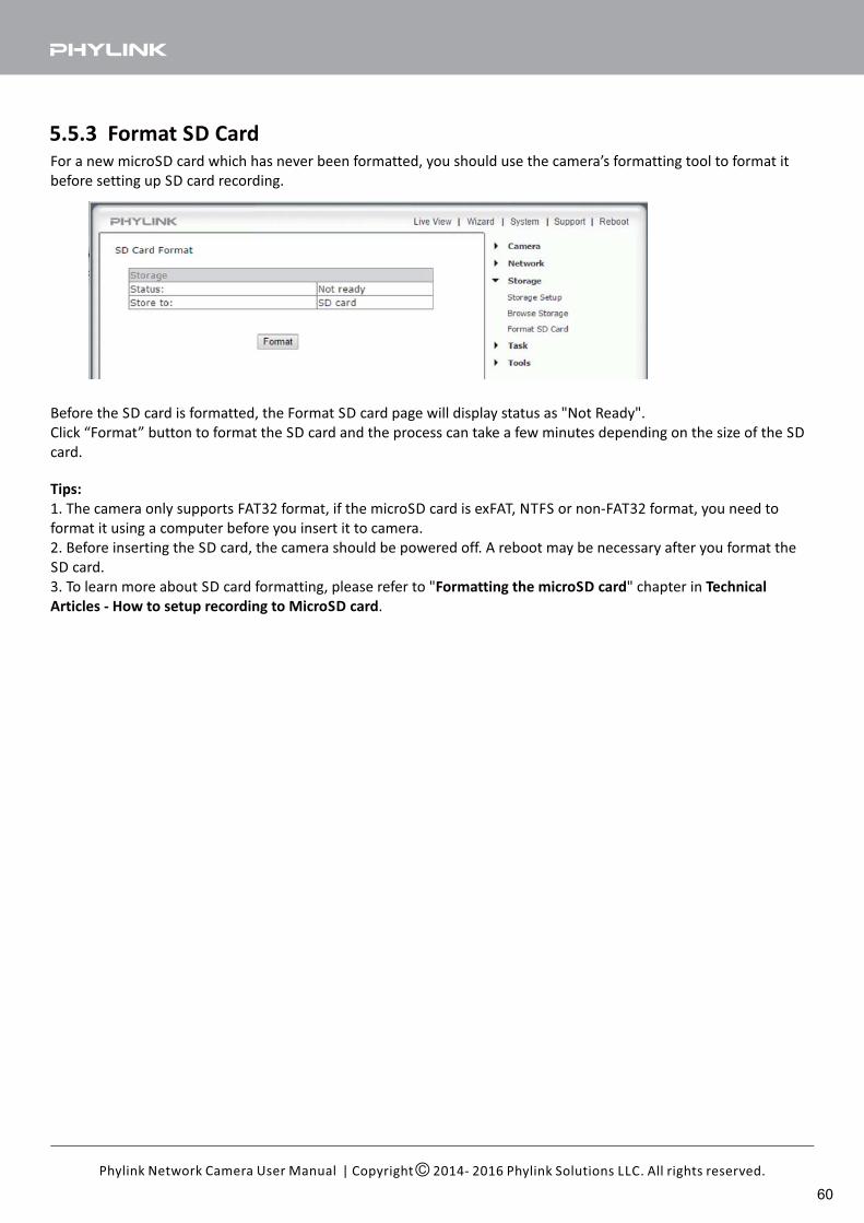
5.5.3 Format SD CardFor a new microSD card which has never been formatted, you should use the camera’s formatting tool to format it
before setting up SD card recording.
Tips:
1. The camera only supports FAT32 format, if the microSD card is exFAT, NTFS or non-FAT32 format, you need to
format it using a computer before you insert it to camera.
2. Before inserting the SD card, the camera should be powered off. A reboot may be necessary after you format the
SD card.
3. To learn more about SD card formatting, please refer to " " chapter inFormatting the microSD card Technical
Articles - How to setup recording to MicroSD card.
Before the SD card is formatted, the Format SD card page will display status as "Not Ready".
Click “Format” button to format the SD card and the process can take a few minutes depending on the size of the SD
card.
| Copyright 2014- 2016 Phylink Solutions LLC. All rights reserved.Phylink Network Camera User Manual
60
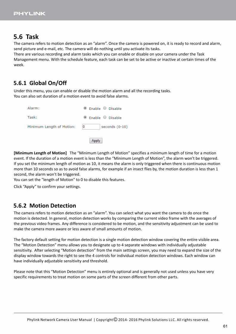
5.6 Task
5.6.1 Global On/Off
The camera refers to motion detection as an “alarm”. Once the camera is powered on, it is ready to record and alarm,
send picture and e-mail, etc. The camera will do nothing until you activate its tasks.
There are various recording and alarm tasks which you can enable or disable on your camera under the Task
Management menu. With the schedule feature, each task can be set to be active or inactive at certain times of the
week.
Under this menu, you can enable or disable the motion alarm and all the recording tasks.
You can also set duration of a motion event to avoid false alarms.
[Minimum Length of Motion] The “Minimum Length of Motion” specifies a minimum length of time for a motion
event. If the duration of a motion event is less than the “Minimum Length of Motion”, the alarm won't be triggered.
If you set the minimum length of motion as 10, it means the alarm is only triggered when there is continuous motion
more than 10 seconds so as to avoid false alarms, for example if an insect flies by, the motion duration is less than 1
second, the alarm won't be triggered.
You can set the "length of Motion" to 0 to disable this features.
Click “Apply” to confirm your settings.
The camera refers to motion detection as an “alarm”. You can select what you want the camera to do once the
motion is detected. In general, motion detection works by comparing the current video frame with the averages of
the previous video frames. Any difference is considered to be motion, and the sensitivity adjustment can be used to
make the camera more aware or less aware of small amounts of motion.
The factory default setting for motion detection is a single motion detection window covering the entire visible area.
The “Motion Detection” menu allows you to designate up to 4 separate windows with individually adjustable
sensitivity. After selecting “Motion detection” from the main settings screen, you may need to expand the size of the
display window towards the right to see the 4 controls for individual motion detection windows. Each window can
have individually adjustable sensitivity and threshold.
Please note that this “Motion Detection” menu is entirely optional and is generally not used unless you have very
specific requirements to treat motion on some parts of the screen different from other parts.
5.6.2 Motion Detection
| Copyright 2014- 2016 Phylink Solutions LLC. All rights reserved.Phylink Network Camera User Manual
61
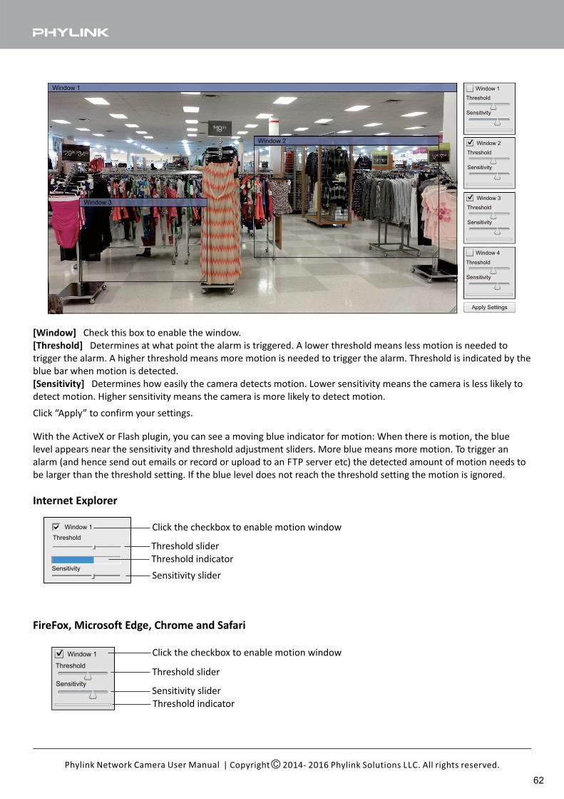
Window 1
Threshold
Sensitivity
Click the checkbox to enable motion window
Threshold slider
With the ActiveX or Flash plugin, you can see a moving blue indicator for motion: When there is motion, the blue
level appears near the sensitivity and threshold adjustment sliders. More blue means more motion. To trigger an
alarm (and hence send out emails or record or upload to an FTP server etc) the detected amount of motion needs to
be larger than the threshold setting. If the blue level does not reach the threshold setting the motion is ignored.
Threshold indicator
Internet Explorer
FireFox, Microsoft Edge, Chrome and Safari
Threshold slider
Threshold indicator
Click the checkbox to enable motion window
Sensitivity slider
Sensitivity slider
[Window] Check this box to enable the window.
[Threshold] Determines at what point the alarm is triggered. A lower threshold means less motion is needed to
trigger the alarm. A higher threshold means more motion is needed to trigger the alarm. Threshold is indicated by the
blue bar when motion is detected.
[Sensitivity] Determines how easily the camera detects motion. Lower sensitivity means the camera is less likely to
detect motion. Higher sensitivity means the camera is more likely to detect motion.
Click “Apply” to confirm your settings.
| Copyright 2014- 2016 Phylink Solutions LLC. All rights reserved.Phylink Network Camera User Manual
62
Tips:1. The Phylink cameras have four motion detection windows which can configured easily on your browser. These four
windows are all salable, and configurable for sensitivity.
To block out some frequently-moving objects which you don't care about, you can uncheck the window that contains
these objects. You can also drag and resize the windows to avoid these objects is contained in the window.
2. To reduce the chance of false alarms you would increase the threshold (move threshold slider to right) or decrease
sensitivity (move sensitivity slider to left).
3. You can NOT adjust the threshold and sensitivity slider to the maximum or minimum.
You should also avoid 4 windows to overlap each other, otherwise the settings will not be saved.
4. Please note that it does not make sense generally to define windows if the camera is not mounted securely. If it is
just sitting on a desktop the slightest movement of the camera would invalidate your window positions.
| Copyright 2014- 2016 Phylink Solutions LLC. All rights reserved.Phylink Network Camera User Manual
63
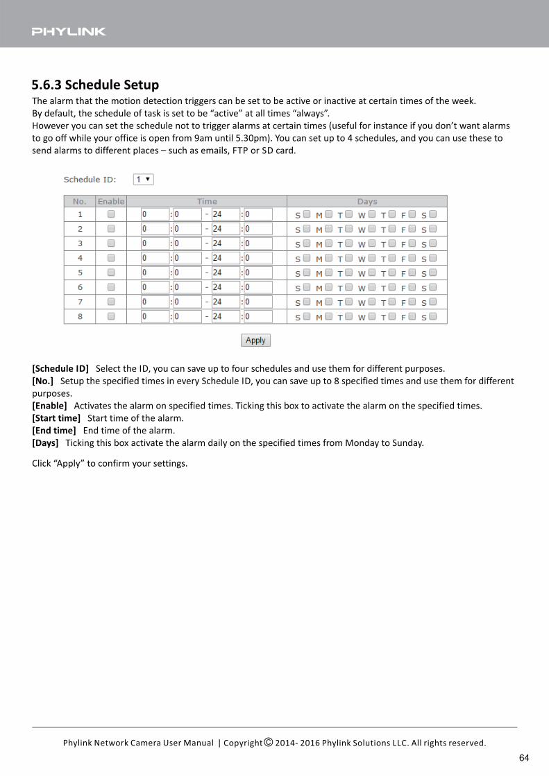
5.6.3 Schedule SetupThe alarm that the motion detection triggers can be set to be active or inactive at certain times of the week.
By default, the schedule of task is set to be “active” at all times “always”.
However you can set the schedule not to trigger alarms at certain times (useful for instance if you don’t want alarms
to go off while your office is open from 9am until 5.30pm). You can set up to 4 schedules, and you can use these to
send alarms to different places – such as emails, FTP or SD card.
[Schedule ID] Select the ID, you can save up to four schedules and use them for different purposes.
[No.] Setup the specified times in every Schedule ID, you can save up to 8 specified times and use them for different
purposes.
[Enable] Activates the alarm on specified times. Ticking this box to activate the alarm on the specified times.
[Start time] Start time of the alarm.
[End time] End time of the alarm.
[Days] Ticking this box activate the alarm daily on the specified times from Monday to Sunday.
Click “Apply” to confirm your settings.
| Copyright 2014- 2016 Phylink Solutions LLC. All rights reserved.Phylink Network Camera User Manual
64
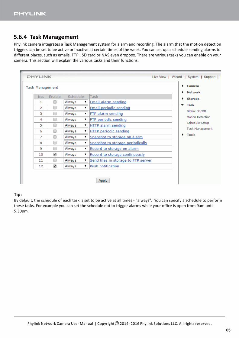
5.6.4 Task ManagementPhylink camera integrates a Task Management system for alarm and recording. The alarm that the motion detection
triggers can be set to be active or inactive at certain times of the week. You can set up a schedule sending alarms to
different places, such as emails, FTP , SD card or NAS even dropbox. There are various tasks you can enable on your
camera. This section will explain the various tasks and their functions.
Tip:By default, the schedule of each task is set to be active at all times - "always". You can specify a schedule to perform
these tasks. For example you can set the schedule not to trigger alarms while your office is open from 9am until
5.30pm.
| Copyright 2014- 2016 Phylink Solutions LLC. All rights reserved.Phylink Network Camera User Manual
65
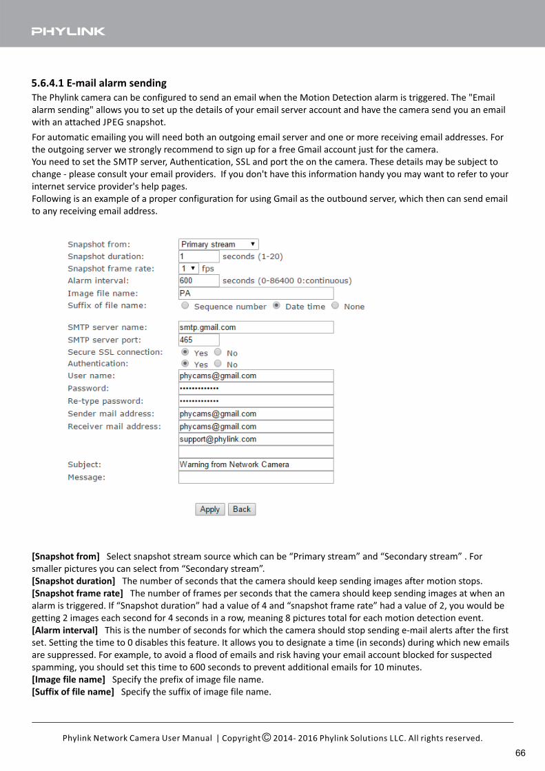
5.6.4.1 E-mail alarm sending
The Phylink camera can be configured to send an email when the Motion Detection alarm is triggered. The "Email
alarm sending" allows you to set up the details of your email server account and have the camera send you an email
with an attached JPEG snapshot.
For automatic emailing you will need both an outgoing email server and one or more receiving email addresses. For
the outgoing server we strongly recommend to sign up for a free Gmail account just for the camera.
You need to set the SMTP server, Authentication, SSL and port the on the camera. These details may be subject to
change - please consult your email providers. If you don't have this information handy you may want to refer to your
internet service provider's help pages.
Following is an example of a proper configuration for using Gmail as the outbound server, which then can send email
to any receiving email address.
[Snapshot from] Select snapshot stream source which can be “Primary stream” and “Secondary stream” . For
smaller pictures you can select from “Secondary stream”.
[Snapshot duration] The number of seconds that the camera should keep sending images after motion stops.
[Snapshot frame rate] The number of frames per seconds that the camera should keep sending images at when an
alarm is triggered. If “Snapshot duration” had a value of 4 and “snapshot frame rate” had a value of 2, you would be
getting 2 images each second for 4 seconds in a row, meaning 8 pictures total for each motion detection event.
[Alarm interval] This is the number of seconds for which the camera should stop sending e-mail alerts after the first
set. Setting the time to 0 disables this feature. It allows you to designate a time (in seconds) during which new emails
are suppressed. For example, to avoid a flood of emails and risk having your email account blocked for suspected
spamming, you should set this time to 600 seconds to prevent additional emails for 10 minutes.
[ ]Image file name Specify the prefix of image file name.
[ ]Suffix of file name Specify the suffix of image file name.
| Copyright 2014- 2016 Phylink Solutions LLC. All rights reserved.Phylink Network Camera User Manual
66
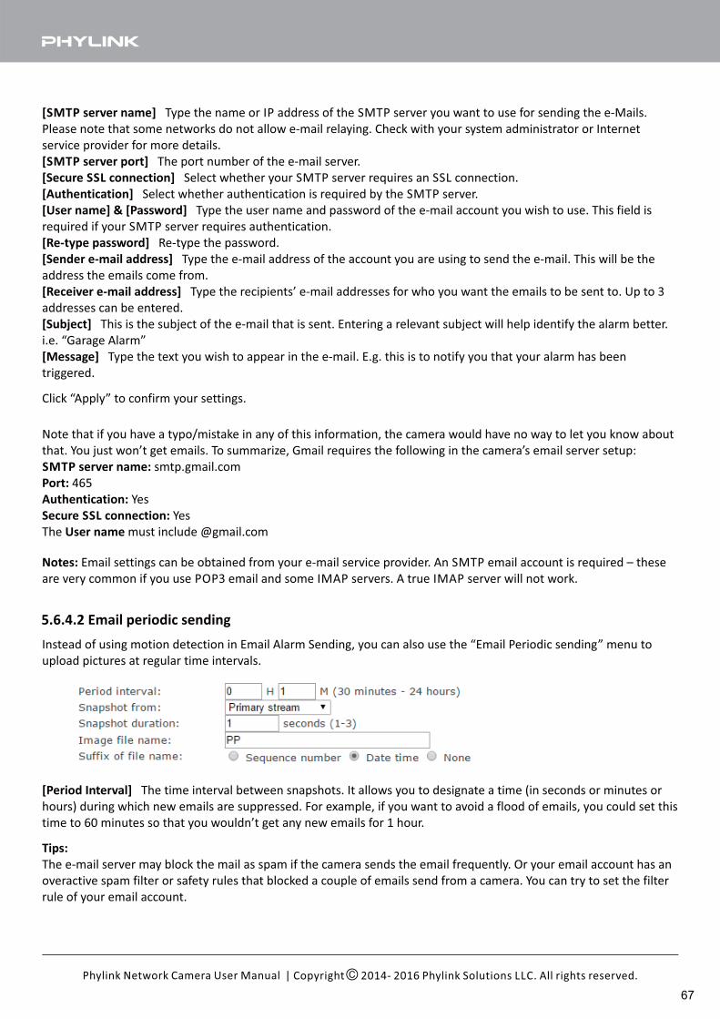
[SMTP server name] Type the name or IP address of the SMTP server you want to use for sending the e-Mails.
Please note that some networks do not allow e-mail relaying. Check with your system administrator or Internet
service provider for more details.
[SMTP server port] The port number of the e-mail server.
[Secure SSL connection] Select whether your SMTP server requires an SSL connection.
[Authentication] Select whether authentication is required by the SMTP server.
[User name] & [Password] Type the user name and password of the e-mail account you wish to use. This field is
required if your SMTP server requires authentication.
[Re-type password] Re-type the password.
[Sender e-mail address] Type the e-mail address of the account you are using to send the e-mail. This will be the
address the emails come from.
[Receiver e-mail address] Type the recipients’ e-mail addresses for who you want the emails to be sent to. Up to 3
addresses can be entered.
[Subject] This is the subject of the e-mail that is sent. Entering a relevant subject will help identify the alarm better.
i.e. “Garage Alarm”
[Message] Type the text you wish to appear in the e-mail. E.g. this is to notify you that your alarm has been
triggered.
Click “Apply” to confirm your settings.
Note that if you have a typo/mistake in any of this information, the camera would have no way to let you know about
that. You just won’t get emails. To summarize, Gmail requires the following in the camera’s email server setup:
SMTP server name: smtp.gmail.com
Port: 465
Authentication: Yes
Secure SSL connection: Yes
The must include @gmail.comUser name
Notes: Email settings can be obtained from your e-mail service provider. An SMTP email account is required – these
are very common if you use POP3 email and some IMAP servers. A true IMAP server will not work.
5.6.4.2 Email periodic sending
Instead of using motion detection in Email Alarm Sending, you can also use the “Email Periodic sending” menu to
upload pictures at regular time intervals.
[Period Interval] The time interval between snapshots. It allows you to designate a time (in seconds or minutes or
hours) during which new emails are suppressed. For example, if you want to avoid a flood of emails, you could set this
time to 60 minutes so that you wouldn’t get any new emails for 1 hour.
Tips:
The e-mail server may block the mail as spam if the camera sends the email frequently. Or your email account has an
overactive spam filter or safety rules that blocked a couple of emails send from a camera. You can try to set the filter
rule of your email account.
| Copyright 2014- 2016 Phylink Solutions LLC. All rights reserved.Phylink Network Camera User Manual
67
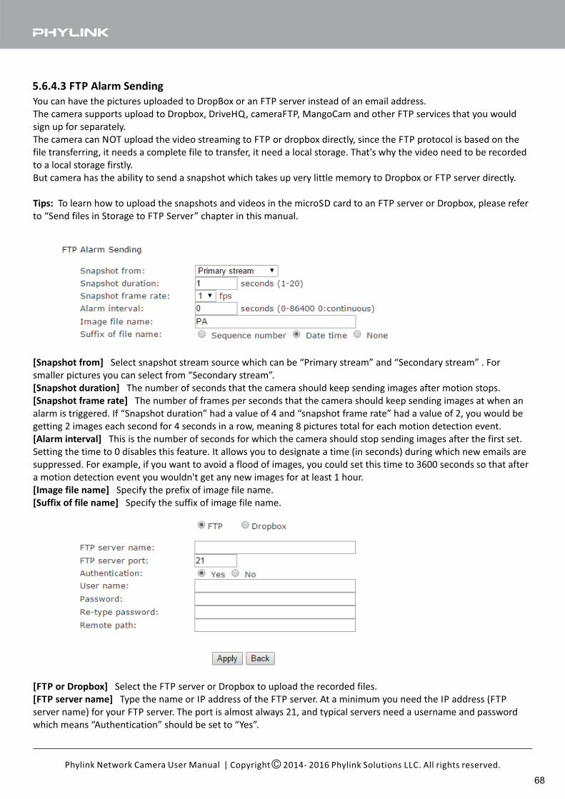
5.6.4.3 FTP Alarm Sending
You can have the pictures uploaded to DropBox or an FTP server instead of an email address.
The camera supports upload to Dropbox, DriveHQ, cameraFTP, MangoCam and other FTP services that you would
sign up for separately.
The camera can NOT upload the video streaming to FTP or dropbox directly, since the FTP protocol is based on the
file transferring, it needs a complete file to transfer, it need a local storage. That's why the video need to be recorded
to a local storage firstly.
But camera has the ability to send a snapshot which takes up very little memory to Dropbox or FTP server directly.
Tips: To learn how to upload the snapshots and videos in the microSD card to an FTP server or Dropbox, please refer
to “Send files in Storage to FTP Server” chapter in this manual.
[Snapshot from] Select snapshot stream source which can be “Primary stream” and “Secondary stream” . For
smaller pictures you can select from “Secondary stream”.
[Snapshot duration] The number of seconds that the camera should keep sending images after motion stops.
[Snapshot frame rate] The number of frames per seconds that the camera should keep sending images at when an
alarm is triggered. If “Snapshot duration” had a value of 4 and “snapshot frame rate” had a value of 2, you would be
getting 2 images each second for 4 seconds in a row, meaning 8 pictures total for each motion detection event.
[Alarm interval] This is the number of seconds for which the camera should stop sending images after the first set.
Setting the time to 0 disables this feature. It allows you to designate a time (in seconds) during which new emails are
suppressed. For example, if you want to avoid a flood of images, you could set this time to 3600 seconds so that after
a motion detection event you wouldn't get any new images for at least 1 hour.
[ ]Image file name Specify the prefix of image file name.
[ ]Suffix of file name Specify the suffix of image file name.
[FTP or Dropbox] Select the FTP server or Dropbox to upload the recorded files.
[FTP server name] Type the name or IP address of the FTP server. At a minimum you need the IP address (FTP
server name) for your FTP server. The port is almost always 21, and typical servers need a username and password
which means “Authentication” should be set to “Yes”.
| Copyright 2014- 2016 Phylink Solutions LLC. All rights reserved.Phylink Network Camera User Manual
68
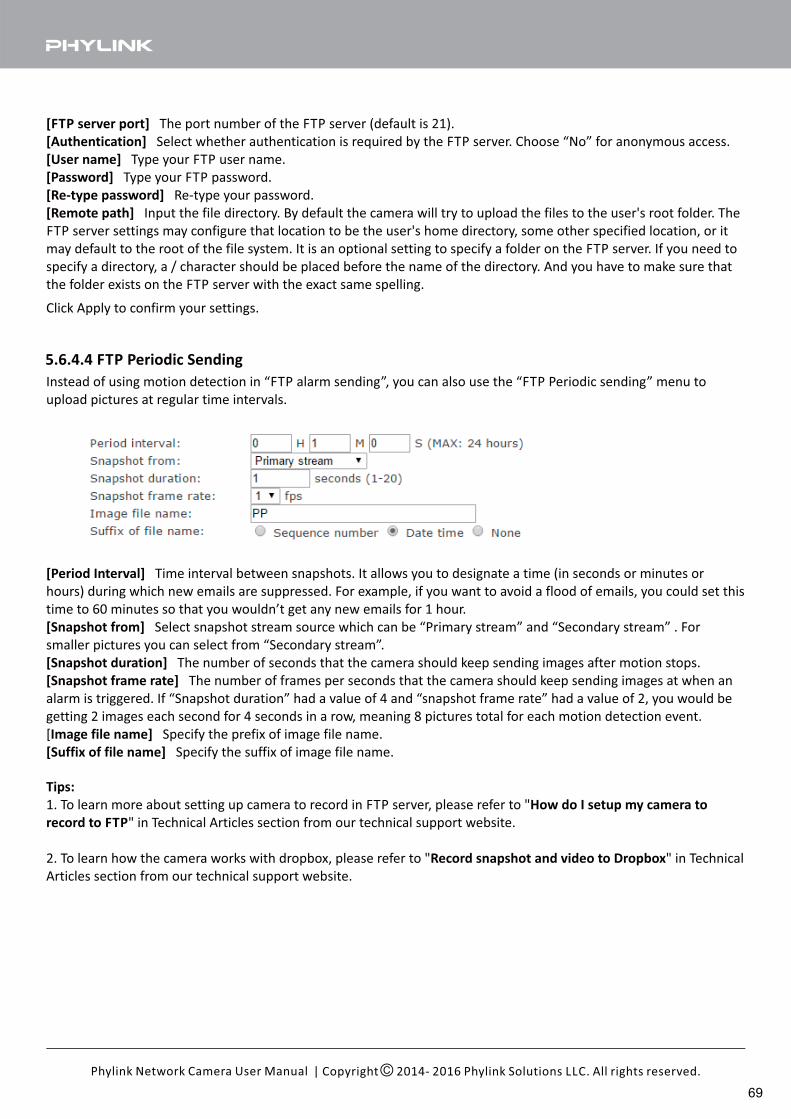
[FTP server port] The port number of the FTP server (default is 21).
[Authentication] Select whether authentication is required by the FTP server. Choose “No” for anonymous access.
[User name] Type your FTP user name.
[Password] Type your FTP password.
[Re-type password] Re-type your password.
[Remote path] Input the file directory. By default the camera will try to upload the files to the user's root folder. The
FTP server settings may configure that location to be the user's home directory, some other specified location, or it
may default to the root of the file system. It is an optional setting to specify a folder on the FTP server. If you need to
specify a directory, a / character should be placed before the name of the directory. And you have to make sure that
the folder exists on the FTP server with the exact same spelling.
Tips:
1. To learn more about setting up camera to record in FTP server, please refer to "How do I setup my camera to
record to FTP" in Technical Articles section from our technical support website.
2. To learn how the camera works with dropbox, please refer to " " in TechnicalRecord snapshot and video to Dropbox
Articles section from our technical support website.
Click Apply to confirm your settings.
5.6.4.4 FTP Periodic Sending
Instead of using motion detection in “FTP alarm sending”, you can also use the “FTP Periodic sending” menu to
upload pictures at regular time intervals.
[Period Interval] Time interval between snapshots. It allows you to designate a time (in seconds or minutes or
hours) during which new emails are suppressed. For example, if you want to avoid a flood of emails, you could set this
time to 60 minutes so that you wouldn’t get any new emails for 1 hour.
[Snapshot from] Select snapshot stream source which can be “Primary stream” and “Secondary stream” . For
smaller pictures you can select from “Secondary stream”.
[Snapshot duration] The number of seconds that the camera should keep sending images after motion stops.
[Snapshot frame rate] The number of frames per seconds that the camera should keep sending images at when an
alarm is triggered. If “Snapshot duration” had a value of 4 and “snapshot frame rate” had a value of 2, you would be
getting 2 images each second for 4 seconds in a row, meaning 8 pictures total for each motion detection event.
[Image file name] Specify the prefix of image file name.
[ ]Suffix of file name Specify the suffix of image file name.
| Copyright 2014- 2016 Phylink Solutions LLC. All rights reserved.Phylink Network Camera User Manual
69
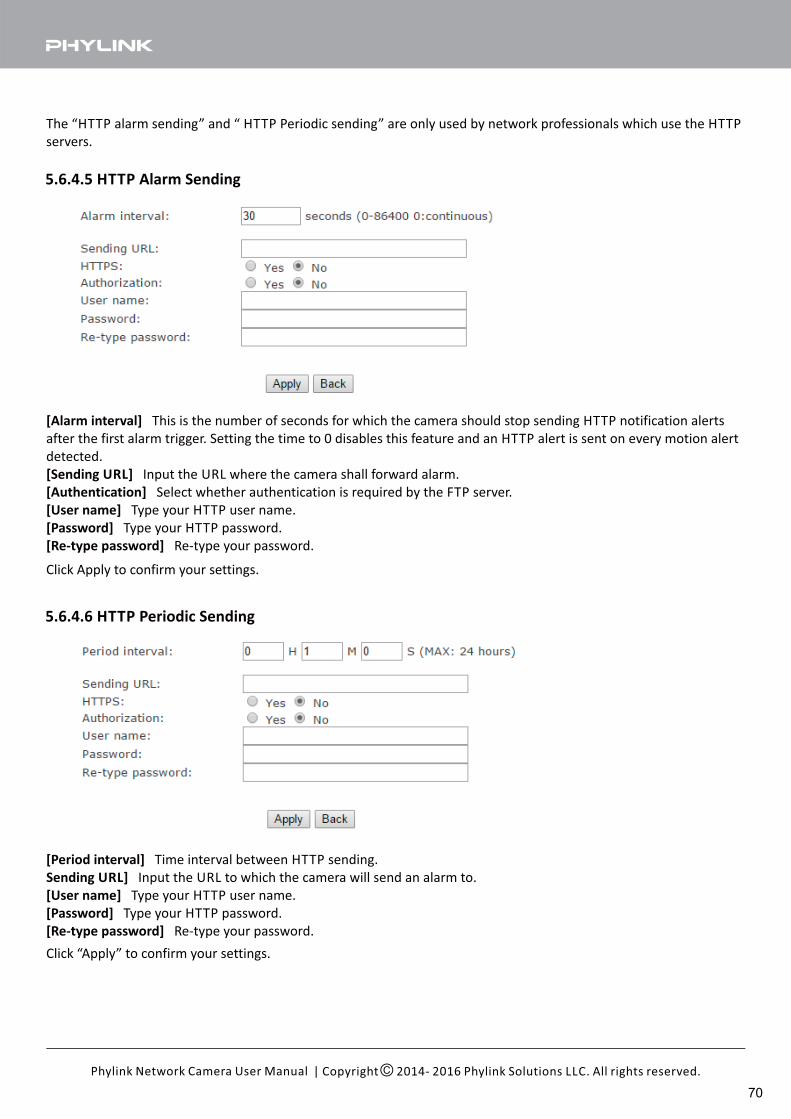
5.6.4.5 HTTP Alarm Sending
5.6.4.6 HTTP Periodic Sending
[Alarm interval] This is the number of seconds for which the camera should stop sending HTTP notification alerts
after the first alarm trigger. Setting the time to 0 disables this feature and an HTTP alert is sent on every motion alert
detected.
[Sending URL] Input the URL where the camera shall forward alarm.
[Authentication] Select whether authentication is required by the FTP server.
[User name] Type your HTTP user name.
[Password] Type your HTTP password.
[Re-type password] Re-type your password.
[Period interval] Time interval between HTTP sending.
Sending URL] Input the URL to which the camera will send an alarm to.
[User name] Type your HTTP user name.
[Password] Type your HTTP password.
[Re-type password] Re-type your password.
The “HTTP alarm sending” and “ HTTP Periodic sending” are only used by network professionals which use the HTTP
servers.
Click “Apply” to confirm your settings.
Click Apply to confirm your settings.
| Copyright 2014- 2016 Phylink Solutions LLC. All rights reserved.Phylink Network Camera User Manual
70
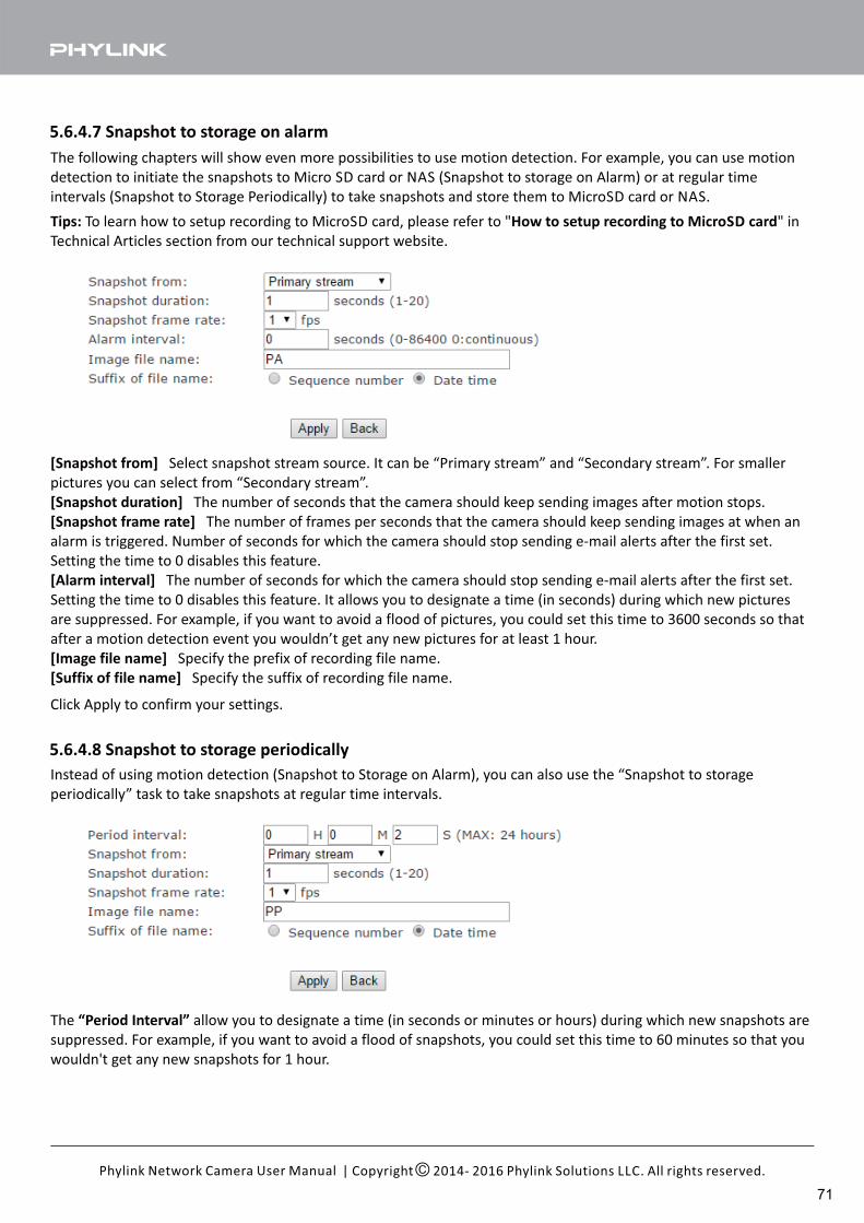
5.6.4.7 Snapshot to storage on alarm
5.6.4.8 Snapshot to storage periodically
The following chapters will show even more possibilities to use motion detection. For example, you can use motion
detection to initiate the snapshots to Micro SD card or NAS (Snapshot to storage on Alarm) or at regular time
intervals (Snapshot to Storage Periodically) to take snapshots and store them to MicroSD card or NAS.
Tips: How to setup recording to MicroSD cardTo learn how to setup recording to MicroSD card, please refer to " " in
Technical Articles section from our technical support website.
[Snapshot from] Select snapshot stream source. It can be “Primary stream” and “Secondary stream”. For smaller
pictures you can select from “Secondary stream”.
[Snapshot duration] The number of seconds that the camera should keep sending images after motion stops.
[Snapshot frame rate] The number of frames per seconds that the camera should keep sending images at when an
alarm is triggered. Number of seconds for which the camera should stop sending e-mail alerts after the first set.
Setting the time to 0 disables this feature.
[Alarm interval] .The number of seconds for which the camera should stop sending e-mail alerts after the first set
Setting the time to 0 disables this feature. It allows you to designate a time (in seconds) during which new pictures
are suppressed. For example, if you want to avoid a flood of pictures, you could set this time to 3600 seconds so that
after a motion detection event you wouldn’t get any new pictures for at least 1 hour.
[Image file name] Specify the prefix of recording file name.
[Suffix of file name] Specify the suffix of recording file name.
Click Apply to confirm your settings.
Instead of using motion detection (Snapshot to Storage on Alarm), you can also use the “Snapshot to storage
periodically” task to take snapshots at regular time intervals.
The allow you to designate a time (in seconds or minutes or hours) during which new snapshots are“Period Interval”
suppressed. For example, if you want to avoid a flood of snapshots, you could set this time to 60 minutes so that you
wouldn't get any new snapshots for 1 hour.
| Copyright 2014- 2016 Phylink Solutions LLC. All rights reserved.Phylink Network Camera User Manual
71
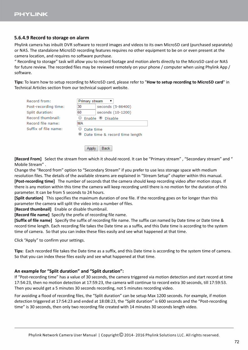
5.6.4.9 Record to storage on alarm
Phylink camera has inbuilt DVR software to record images and videos to its own MicroSD card (purchased separately)
or NAS. The standalone MicroSD recording features requires no other equipment to be on or even present at the
camera location, and requires no software purchase.
“ Recording to storage” task will allow you to record footage and motion alerts directly to the MicroSD card or NAS
for future review. The recorded files may be reviewed remotely on your phone / computer when using Phylink App /
software.
[Record From] Select the stream from which it should record. It can be “Primary stream” , “Secondary stream” and “
Mobile Stream” .
Change the “Record from” option to “Secondary Stream” if you prefer to use less storage space with medium
resolution files. The details of the available streams are explained in “Stream Setup” chapter within this manual.
[Post-recording time] The number of seconds that the camera should keep recording video after motion stops. If
there is any motion within this time the camera will keep recording until there is no motion for the duration of this
parameter. It can be from 5 seconds to 24 hours.
[Split duration] This specifies the maximum duration of one file. If the recording goes on for longer than this
parameter the camera will split the video into a number of files.
[Record thumbnail] Enable or disable thumbnail.
[Record file name] Specify the prefix of recording file name.
[Suffix of file name] Specify the suffix of recording file name. The suffix can named by Date time or Date time &
record time length. Each recording file takes the Date time as a suffix, and this Date time is according to the system
time of camera. So that you can index these files easily and see what happened at that time.
Click “Apply” to confirm your settings.
An example for “Split duration” and “Split duration”:
If “Post-recording time” has a value of 30 seconds, the camera triggered via motion detection and start record at time
17:54:23, then no motion detection at 17:59:23, the camera will continue to record extra 30 seconds, till 17:59:53.
Then you would get a 5 minutes 30 seconds recording, not 5 minutes recording video.
For avoiding a flood of recording files, the “Split duration” can be setup Max 1200 seconds. For example, if motion
detection triggered at 17:54:23 and ended at 18:08:23, the “Split duration” is 600 seconds and the “Post-recording
time” is 30 seconds, then only two recording file created with 14 minutes 30 seconds length video.
Tips: How to setup recording to MicroSD cardTo learn how to setup recording to MicroSD card, please refer to " " in
Technical Articles section from our technical support website.
Tips: Each recorded file takes the Date time as a suffix, and this Date time is according to the system time of camera.
So that you can index these files easily and see what happened at that time.
| Copyright 2014- 2016 Phylink Solutions LLC. All rights reserved.Phylink Network Camera User Manual
72
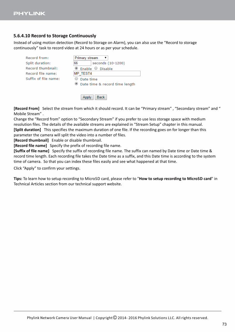
5.6.4.10 Record to Storage Continuously
[Record From] Select the stream from which it should record. It can be “Primary stream” , “Secondary stream” and “
Mobile Stream” .
Change the “Record from” option to “Secondary Stream” if you prefer to use less storage space with medium
resolution files. The details of the available streams are explained in “Stream Setup” chapter in this manual.
[Split duration] This specifies the maximum duration of one file. If the recording goes on for longer than this
parameter the camera will split the video into a number of files.
[Record thumbnail] Enable or disable thumbnail.
[Record file name] Specify the prefix of recording file name.
[Suffix of file name] Specify the suffix of recording file name. The suffix can named by Date time or Date time &
record time length. Each recording file takes the Date time as a suffix, and this Date time is according to the system
time of camera. So that you can index these files easily and see what happened at that time.
Instead of using motion detection (Record to Storage on Alarm), you can also use the “Record to storage
continuously” task to record video at 24 hours or as per your schedule.
Click “Apply” to confirm your settings.
Tips: How to setup recording to MicroSD cardTo learn how to setup recording to MicroSD card, please refer to " " in
Technical Articles section from our technical support website.
| Copyright 2014- 2016 Phylink Solutions LLC. All rights reserved.Phylink Network Camera User Manual
73
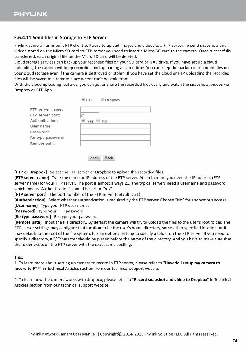
5.6.4.11 Send files in Storage to FTP Server
[FTP or Dropbox] Select the FTP server or Dropbox to upload the recorded files.
[FTP server name] Type the name or IP address of the FTP server. At a minimum you need the IP address (FTP
server name) for your FTP server. The port is almost always 21, and typical servers need a username and password
which means “Authentication” should be set to “Yes”.
[FTP server port] The port number of the FTP server (default is 21).
[Authentication] Select whether authentication is required by the FTP server. Choose “No” for anonymous access.
[User name] Type your FTP user name.
[Password] Type your FTP password.
[Re-type password] Re-type your password.
[Remote path] Input the file directory. By default the camera will try to upload the files to the user's root folder. The
FTP server settings may configure that location to be the user's home directory, some other specified location, or it
may default to the root of the file system. It is an optional setting to specify a folder on the FTP server. If you need to
specify a directory, a “/ “character should be placed before the name of the directory. And you have to make sure that
the folder exists on the FTP server with the exact same spelling.
Phylink camera has in-built FTP client software to upload images and videos to a FTP server. To send snapshots and
videos stored on the Micro SD card to FTP server you need to insert a Micro SD card to the camera. Once successfully
transferred, each original file on the Micro SD card will be deleted.
Cloud storage services can backup your recorded files on your SD card or NAS drive. If you have set up a cloud
uploading, the camera will keep recording and uploading at same time. You can keep the backup of recorded files on
your cloud storage even if the camera is destroyed or stolen. If you have set the cloud or FTP uploading the recorded
files will be saved to a remote place where can't be stole from.
With the cloud uploading features, you can get or share the recorded files easily and watch the snapshots, videos via
Dropbox or FTP App.
Tips:
1. To learn more about setting up camera to record in FTP server, please refer to "How do I setup my camera to
record to FTP" in Technical Articles section from our technical support website.
2. To learn how the camera works with dropbox, please refer to " " in TechnicalRecord snapshot and video to Dropbox
Articles section from our technical support website.
| Copyright 2014- 2016 Phylink Solutions LLC. All rights reserved.Phylink Network Camera User Manual
74
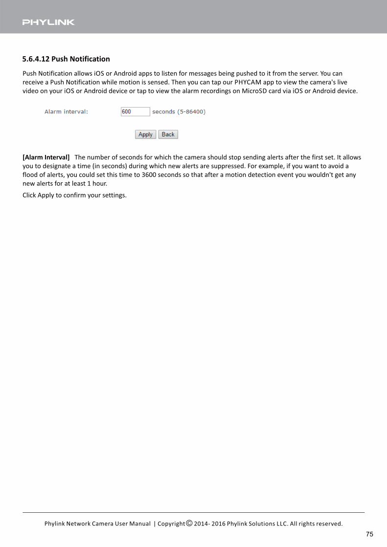
5.6.4.12 Push Notification
Push Notification allows iOS or Android apps to listen for messages being pushed to it from the server. You can
receive a Push Notification while motion is sensed. Then you can tap our PHYCAM app to view the camera's live
video on your iOS or Android device or tap to view the alarm recordings on MicroSD card via iOS or Android device.
Click Apply to confirm your settings.
[Alarm Interval] The number of seconds for which the camera should stop sending alerts after the first set. It allows
you to designate a time (in seconds) during which new alerts are suppressed. For example, if you want to avoid a
flood of alerts, you could set this time to 3600 seconds so that after a motion detection event you wouldn't get any
new alerts for at least 1 hour.
| Copyright 2014- 2016 Phylink Solutions LLC. All rights reserved.Phylink Network Camera User Manual
75
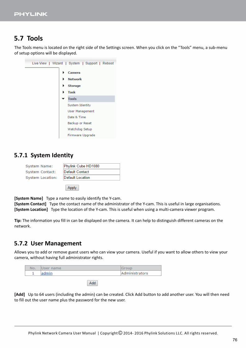
The Tools menu is located on the right side of the Settings screen. When you click on the “Tools” menu, a sub-menu
of setup options will be displayed.
[Add] Up to 64 users (including the admin) can be created. Click Add button to add another user. You will then need
to fill out the user name plus the password for the new user.
5.7 Tools
5.7.1 System Identity
[System Name] Type a name to easily identify the Y-cam.
[System Contact] Type the contact name of the administrator of the Y-cam. This is useful in large organisations.
[System Location] Type the location of the Y-cam. This is useful when using a multi-camera viewer program.
Tip: The information you fill in can be displayed on the camera. It can help to distinguish different cameras on the
network.
5.7.2 User Management
Allows you to add or remove guest users who can view your camera. Useful if you want to allow others to view your
camera, without having full administrator rights.
| Copyright 2014- 2016 Phylink Solutions LLC. All rights reserved.Phylink Network Camera User Manual
76
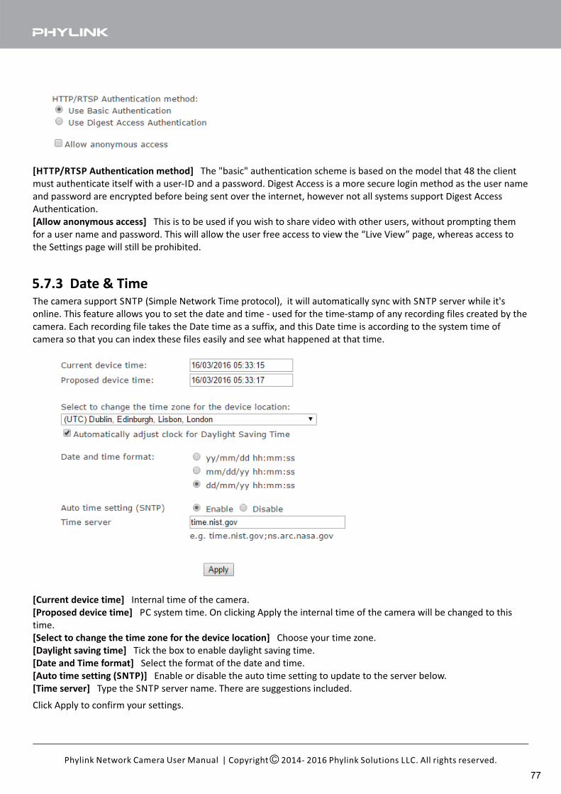
[HTTP/RTSP Authentication method] The "basic" authentication scheme is based on the model that 48 the client
must authenticate itself with a user-ID and a password. Digest Access is a more secure login method as the user name
and password are encrypted before being sent over the internet, however not all systems support Digest Access
Authentication.
[Allow anonymous access] This is to be used if you wish to share video with other users, without prompting them
for a user name and password. This will allow the user free access to view the “Live View” page, whereas access to
the Settings page will still be prohibited.
5.7.3 Date & TimeThe camera support SNTP (Simple Network Time protocol), it will automatically sync with SNTP server while it's
online. This feature allows you to set the date and time - used for the time-stamp of any recording files created by the
camera. Each recording file takes the Date time as a suffix, and this Date time is according to the system time of
camera so that you can index these files easily and see what happened at that time.
[Current device time] Internal time of the camera.
[Proposed device time] PC system time. On clicking Apply the internal time of the camera will be changed to this
time.
[Select to change the time zone for the device location] Choose your time zone.
[Daylight saving time] Tick the box to enable daylight saving time.
[Date and Time format] Select the format of the date and time.
[Auto time setting (SNTP)] Enable or disable the auto time setting to update to the server below.
[Time server] Type the SNTP server name. There are suggestions included.
Click Apply to confirm your settings.
| Copyright 2014- 2016 Phylink Solutions LLC. All rights reserved.Phylink Network Camera User Manual
77
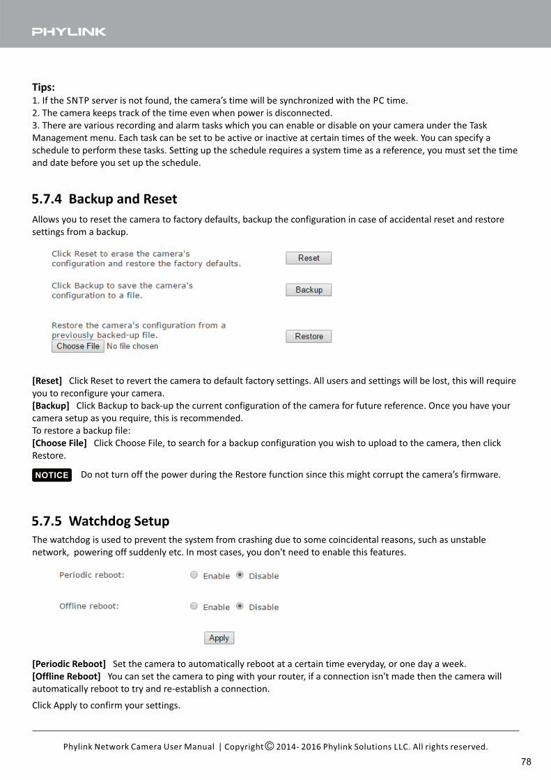
[Periodic Reboot] Set the camera to automatically reboot at a certain time everyday, or one day a week.
[Offline Reboot] You can set the camera to ping with your router, if a connection isn't made then the camera will
automatically reboot to try and re-establish a connection.
Allows you to reset the camera to factory defaults, backup the configuration in case of accidental reset and restore
settings from a backup.
5.7.4 Backup and Reset
Tips:1. If the SNTP server is not found, the camera’s time will be synchronized with the PC time.
2. The camera keeps track of the time even when power is disconnected.
3. There are various recording and alarm tasks which you can enable or disable on your camera under the Task
Management menu. Each task can be set to be active or inactive at certain times of the week. You can specify a
schedule to perform these tasks. Setting up the schedule requires a system time as a reference, you must set the time
and date before you set up the schedule.
[Reset] Click Reset to revert the camera to default factory settings. All users and settings will be lost, this will require
you to reconfigure your camera.
[Backup] Click Backup to back-up the current configuration of the camera for future reference. Once you have your
camera setup as you require, this is recommended.
To restore a backup file:
[Choose File] Click Choose File, to search for a backup configuration you wish to upload to the camera, then click
Restore.
Do not turn off the power during the Restore function since this might corrupt the camera’s firmware.
5.7.5 Watchdog Setup
Click Apply to confirm your settings.
The watchdog is used to prevent the system from crashing due to some coincidental reasons, such as unstable
network, powering off suddenly etc. In most cases, you don't need to enable this features.
| Copyright 2014- 2016 Phylink Solutions LLC. All rights reserved.Phylink Network Camera User Manual
NOTICE
78
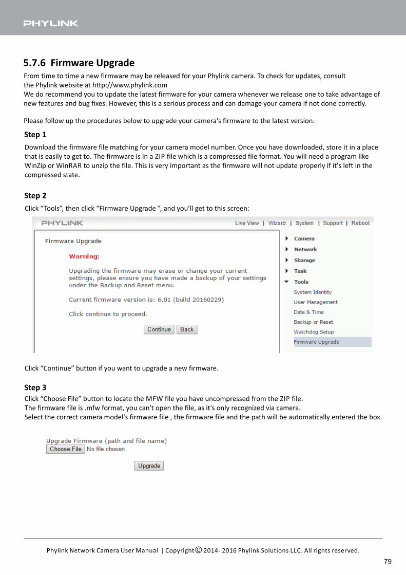
Click “Continue” button if you want to upgrade a new firmware.
5.7.6 Firmware UpgradeFrom time to time a new firmware may be released for your Phylink camera. To check for updates, consult
the Phylink website at http://www.phylink.com
We do recommend you to update the latest firmware for your camera whenever we release one to take advantage of
new features and bug fixes. However, this is a serious process and can damage your camera if not done correctly.
Please follow up the procedures below to upgrade your camera's firmware to the latest version.
Step 1
Download the firmware file matching for your camera model number. Once you have downloaded, store it in a place
that is easily to get to. The firmware is in a ZIP file which is a compressed file format. You will need a program like
WinZip or WinRAR to unzip the file. This is very important as the firmware will not update properly if it's left in the
compressed state.
Step 2
Click “Tools”, then click “Firmware Upgrade ”, and you’ll get to this screen:
Step 3
Click “Choose File” button to locate the MFW file you have uncompressed from the ZIP file.
The firmware file is .mfw format, you can't open the file, as it's only recognized via camera.
Select the correct camera model's firmware file , the firmware file and the path will be automatically entered the box.
| Copyright 2014- 2016 Phylink Solutions LLC. All rights reserved.Phylink Network Camera User Manual
79
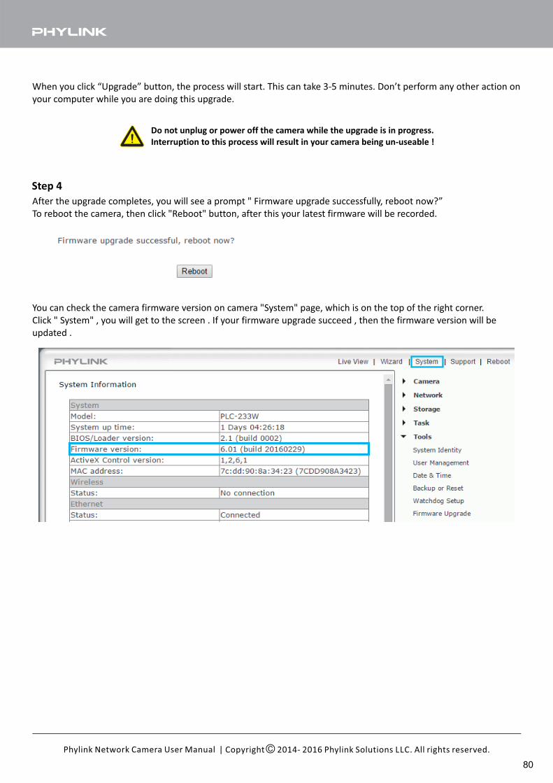
When you click “Upgrade” button, the process will start. This can take 3-5 minutes. Don’t perform any other action on
your computer while you are doing this upgrade.
Step 4
After the upgrade completes, you will see a prompt " Firmware upgrade successfully, reboot now?”
To reboot the camera, then click "Reboot" button, after this your latest firmware will be recorded.
You can check the camera firmware version on camera "System" page, which is on the top of the right corner.
Click " System" , you will get to the screen . If your firmware upgrade succeed , then the firmware version will be
updated .
Do not unplug or power off the camera while the upgrade is in progress.
Interruption to this process will result in your camera being un-useable !
| Copyright 2014- 2016 Phylink Solutions LLC. All rights reserved.Phylink Network Camera User Manual
80
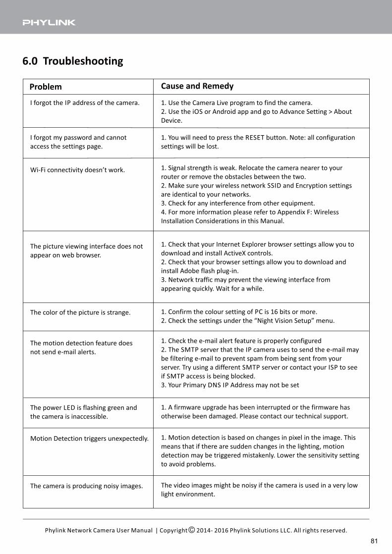
6.0 Troubleshooting
| Copyright 2014- 2016 Phylink Solutions LLC. All rights reserved.Phylink Network Camera User Manual
Problem Cause and Remedy
I forgot the IP address of the camera. 1. Use the Camera Live program to find the camera.
2. Use the iOS or Android app and go to Advance Setting > About
Device.
I forgot my password and cannot
access the settings page.
1. You will need to press the RESET button. Note: all configuration
settings will be lost.
Wi-Fi connectivity doesn’t work. 1. Signal strength is weak. Relocate the camera nearer to your
router or remove the obstacles between the two.
2. Make sure your wireless network SSID and Encryption settings
are identical to your networks.
3. Check for any interference from other equipment.
4. For more information please refer to Appendix F: Wireless
Installation Considerations in this Manual.
The picture viewing interface does not
appear on web browser.
1. Check that your Internet Explorer browser settings allow you to
download and install ActiveX controls.
2. Check that your browser settings allow you to download and
install Adobe flash plug-in.
3. Network traffic may prevent the viewing interface from
appearing quickly. Wait for a while.
The color of the picture is strange. 1. Confirm the colour setting of PC is 16 bits or more.
2. Check the settings under the “Night Vision Setup” menu.
The motion detection feature does
not send e-mail alerts.
1. Check the e-mail alert feature is properly configured
2. The SMTP server that the IP camera uses to send the e-mail may
be filtering e-mail to prevent spam from being sent from your
server. Try using a different SMTP server or contact your ISP to see
if SMTP access is being blocked.
3. Your Primary DNS IP Address may not be set
The power LED is flashing green and
the camera is inaccessible.
1. A firmware upgrade has been interrupted or the firmware has
otherwise been damaged. Please contact our technical support.
Motion Detection triggers unexpectedly. 1. Motion detection is based on changes in pixel in the image. This
means that if there are sudden changes in the lighting, motion
detection may be triggered mistakenly. Lower the sensitivity setting
to avoid problems.
The camera is producing noisy images. The video images might be noisy if the camera is used in a very low
light environment.
81
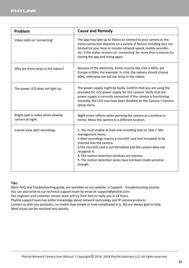
| Copyright 2014- 2016 Phylink Solutions LLC. All rights reserved.Phylink Network Camera User Manual
Problem Cause and Remedy
Video stalls on 'connecting’ The app may take up to 30secs to connect to your camera as the
initial connection depends on a variety of factors including (but not
limited to) your local or remote network speed, mobile provider,
etc. If the status remains on 'connecting' for more than a minute try
closing the app and trying again.
Why are there strips in the videos? Because of the electricity. Some country like USA is 60Hz, yet
Europe is 50Hz. For example: In USA, the camera should choose
60Hz, otherwise we will see strips in the videos.
The power LED does not light up. The power supply might be faulty. Confirm that you are using the
provided DC 12V power supply for this camera. Verify that the
power supply is correctly connected. If the camera is functioning
normally, the LED may have been disabled on the Camera > Camera
Setup menu.
Bright spot in video when viewing
camera at night.Night vision reflects when pointing the camera at a window or
mirror. Move the camera to a different location.
Cannot view alert recordings. 1. You must enable at least one recording task on Task > Taks
managemant menu.
2.Alert recordings require a microSD card (not included) to be
inserted into the camera.
3.The microSD card is not formatted and the camera dose not
recognize it.
4. The motion detection windows are inactive.
5. The motion detection zones have not been made sensitive
enough.
Tips:
More FAQ and Troubleshooting guide, are available on our website, in Support - Troubleshooting section.
You can also write to our technical support team by email at: [email protected].
Our engineer and customer service team will try their best to reply you in 24 hours.
Phylink support team has better knowledge about network technology and IP camera products.
Contact us with any questions, no matter how simple or how complicated it is. We are always glad to help.
Most issues can be resolved very quickly.
82
7.0 Glossary of Terms
Adhoc ModeA wireless network system in which devices communicate directly with each other, without the use of a wireless router.
DDNS
DDNS is a method of keeping a domain name linked to a dynamic IP address with your Network Camera. You can set up your DDNS service and the device will automatically update your DDNS server each time it alter a different IP address.
DHCPDynamic Host Configuration Protocol is a set of rules used by communications devices such as a computer, router or network adapter to allow the device to request and obtain an IP address from a server which has a list of addresses available for assignment.
FirmwareThe firmware is the software in your Y-cam that makes the hardware functional and allows you to use the many features of your wireless IP Camera.
FTPFile Transfer Protocol. Network cameras equipped with an embedded operating system, such as Linux, can use FTP to send images to a website.
Gateway AddressIP address of the gateway through which the IP camera is connected.
IEEE 802.11b/g/nThe specifications developed by the IEEE for wireless network technology. It provides 11 Mbps transmission in the 2.4GHz band usage.
Infrastructure ModeOne of the wireless network system in which devices communicate with each other by first going through the wireless router.
IP AddressThe unique 32 bit number assigned to each computer connected to the Internet. IP numbers are used by the TCP/IP protocol to route packets of data to their destinations.
JPEGA standard image format, used widely for photographs, also known as JPG.
Network CameraA stand-alone device which allows users to view live, full motion video from anywhere on a computer network, even over the Internet, using a standard web browser.
Primary DNSIP address of the primary DNS server, if configured for the IP camera.
Subnet MaskSubnet mask of the LAN to which the IP camera is connected.
| Copyright 2014- 2016 Phylink Solutions LLC. All rights reserved.Phylink Network Camera User Manual
83
TCP/IPThe collection of "protocols" underlying the functioning of the Internet. Each computer connected to the Internet is identified by a unique IP Address.
Time serverA time server consists of a computer networking device that reads the actual time from a reference clock and distributes this information to its clients using a computer network.
UPnPUniversal Plug and Play is architecture for pervasive peer-to-peer network connectivity of intelligent appliances and wireless devices.
WEPWireless Equivalent Privacy. A security protocol for wireless network defined in the IEEE 802.11b/g standard. WEP aims to provide security by encrypting data over radio waves so that it is protected as it is transmitted from one end point to another.
SMTPSimple Mail Transfer Protocol.
Tip: To understand more details for network terminology, please refer to Appendix A: A Quick Review of Networking
Terminology.
| Copyright 2014- 2016 Phylink Solutions LLC. All rights reserved.Phylink Network Camera User Manual
84
To participate in a computer network, each device needs an “Internet Protocol” address that is unique on that network. This IP address consists of 4 groups of numbers separated by periods. For example: 192.168.0.2IP addresses are assigned to a device either automatically by the router or manually by a person who is setting up the network. The router is the device that is managing the addresses and the flow of data between those addresses on your network. Sometimes the routing function is not provided by a separate device and is built into your cable modem or DSL modem.When you first plug the camera into your router with the network cable, the camera asks the router to get a valid IP address, and the router provides the next available IP address on the local network. With “local network” or LAN we’re referring to your own home or business network. On the other hand, the term WAN or “Wide Area Network” refers to the global internet.Your router is sometimes also called a gateway because it is like a gateway from your own local network to the internet. Unless you have an all-in-one combination of modem and router you’ll probably see that your router has one network jack marked WAN which connects to the cable or DSL modem and a set of 2 or 4 jacks marked LAN for your local network devices.Your router will have 2 IP addresses of its own, a WAN IP address that identifies it on the internet and a LAN IP address that identifies it on your local network. The LAN IP addresses often start with 192.168 or 10.0From any computer on your network it is easy to find the WAN IP address of your router just by opening a browser and going to www.checkip.orgSince your own private network devices including your camera are not directly visible from the internet, for remote access you would typically use your router’s WAN IP address together with some instructions to your router to forward the requests from the internet to your camera.The messages going back and forth between the camera and the router regarding the initial IP address are called DHCP for “Dynamic Host Configuration Protocol”.Each device also has a unique hardware address that is called a MAC address. This MAC address is unrelated to Macintosh computers. What’s special about this hardware address is that it is totally unique to each network device.
8.0 Appendix
Appendix A: A Quick Review of Networking Terminology
| Copyright 2014- 2016 Phylink Solutions LLC. All rights reserved.Phylink Network Camera User Manual
85
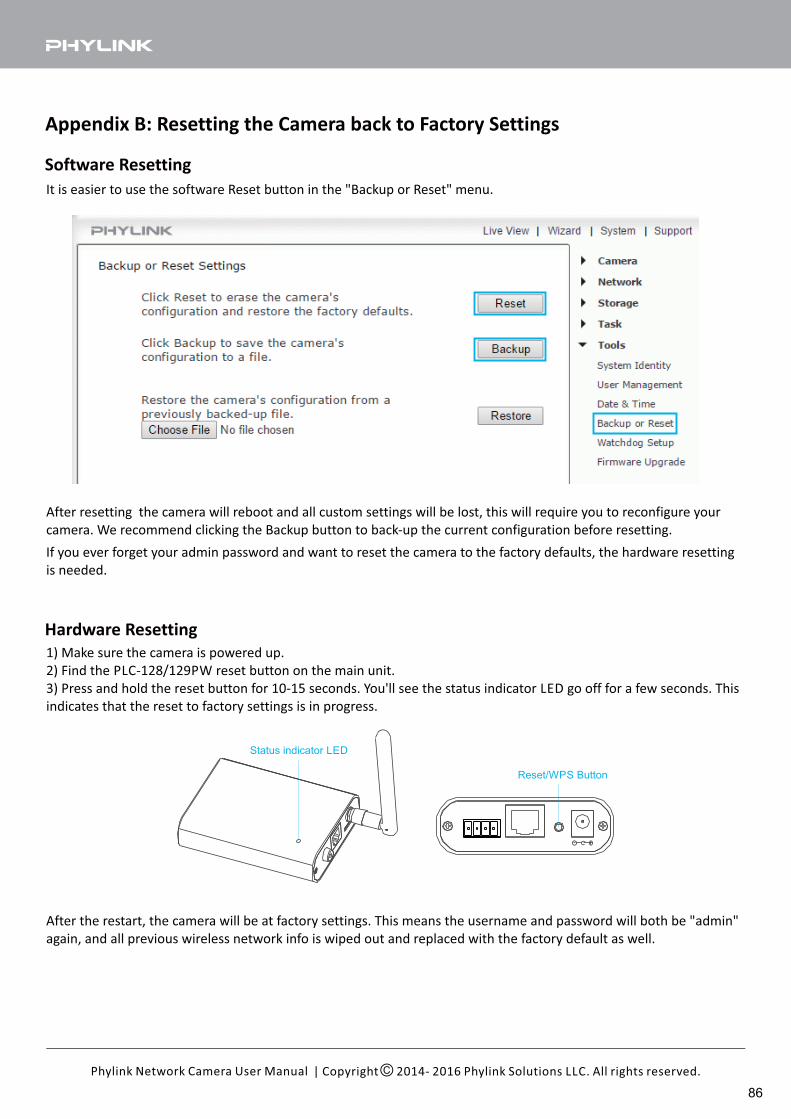
Appendix B: Resetting the Camera back to Factory Settings
It is easier to use the software Reset button in the "Backup or Reset" menu.
After resetting the camera will reboot and all custom settings will be lost, this will require you to reconfigure your
camera. We recommend clicking the Backup button to back-up the current configuration before resetting.
If you ever forget your admin password and want to reset the camera to the factory defaults, the hardware resetting
is needed.
Hardware Resetting
1) Make sure the camera is powered up.
2) Find the PLC-128/129PW reset button on the main unit.
3) Press and hold the reset button for 10-15 seconds. You'll see the status indicator LED go off for a few seconds. This
indicates that the reset to factory settings is in progress.
After the restart, the camera will be at factory settings. This means the username and password will both be "admin"
again, and all previous wireless network info is wiped out and replaced with the factory default as well.
| Copyright 2014- 2016 Phylink Solutions LLC. All rights reserved.Phylink Network Camera User Manual
Reset/WPS Button
Status indicator LED
Software Resetting
86
Appendix C: Connecting the Camera directly to a Computer
You can connect the camera directly to a computer. Please note, in this mode you will not be able to view your
camera from anywhere else apart from the computer you are currently using.
Tips:
1. We don't recommend that you connect the camera to computer directly. If you don't have some basic network
background, connecting the a IP camera to your computer is a challenge for you.
2. The camera's default IP address is 192.168.168.100 without router's DHCP server.
Also, you computer can not get a Dynamic IP without router's DHCP server. So you have to change your computer's
IP address. You will need to put the same numbers for the first 3 fields (192.168.168) but change the fourth field to
another number. That means your camera must be same network segment with your computer.
On a PC:1. Open the Control Panel and double click on “Network Connections” then right click on your “Local Area Network”
connection, and click “Properties”. Be sure to select the Network icon that corresponds to where you have plugged
the camera in to – so this would not be listed as a Wireless, Wi-Fi or Bluetooth Network.
2. Select “Internet Protocol (TCP/IP)” then click Properties.
3. Take note of your current TCP/IP Settings and then click on “Use the following IP settings”
4. In the “IP Address” Field type in the number 192.168.168.20
5. In the “Subnet Mask” type in 255.255.255.0
6. In the “Default Gateway” type 192.168.168.1 or leave it blank(The camera will automatically assign itself this IP
address when no DHCP server is present)
7. Leave DNS server settings blank.
8. Click “OK” then “Close” to apply these settings.
9. Turn the power on to the camera.
10. The Status indicator LED on the camera will light up.
You can now proceed to the Software Installation section.
On a Mac:1. Open “System Preferences” from the dock, and then select “Network” to edit your network settings. As the Y-cam
is connected to your Mac using a cable we must choose the “Built-in-Ethernet” option. Select “Built-in Ethernet” and
click the “Configure” button. Make a note of your current TCP/IP Settings.
2. Select “Manually” from the IPv4 drop-down box at the top of the dialog, and then enter these settings:
IP Address: 192.168.168.20
Subnet Mask: 255.255.255.0
Router/Default Gateway: 192.168.168.1 or leave it blank
DNS Servers: Leave blank, not important at this stage.
Search domains: Optional, leave blank, not important.
3. Click “Apply Now”.
4. Turn the power on to the camera.
5. The Status indicator LED on the camera will light up.
You can now proceed to the Software Installation section.
1. Connect one end of the network cable in to the Camera Network Connection socket, and plug the other end in to a
spare network port on your computer.
2. Connect the included power adapter to the power port on the camera and the other end into an electrical socket.
Do not turn the power on at this time. You must then assign your computer an IP address so it can talk easily to the
camera.
To connect your camera directly to a computer, please follow the following steps.
| Copyright 2014- 2016 Phylink Solutions LLC. All rights reserved.Phylink Network Camera User Manual
87
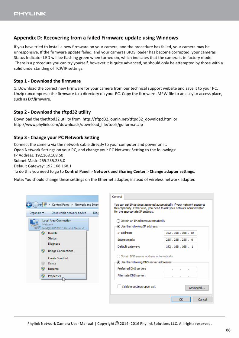
Appendix D: Recovering from a failed Firmware update using Windows
If you have tried to install a new firmware on your camera, and the procedure has failed, your camera may be
unresponsive. If the firmware update failed, and your cameras BIOS loader has become corrupted, your cameras
Status Indicator LED will be flashing green when turned on, which indicates that the camera is in factory mode.
There is a procedure you can try yourself, however it is quite advanced, so should only be attempted by those with a
solid understanding of TCP/IP settings.
Step 1 - Download the firmware
1. Download the correct new firmware for your camera from our technical support website and save it to your PC.
Unzip (uncompress) the firmware to a directory on your PC. Copy the firmware .MFW file to an easy to access place,
such as D:\firmware.
Connect the camera via the network cable directly to your computer and power on it.
Open Network Settings on your PC, and change your PC Network Setting to the followings:
IP Address: 192.168.168.50
Subnet Mask: 255.255.255.0
Default Gateway: 192.168.168.1
To do this you need to go to > > .Control Panel Network and Sharing Center Change adapter settings
Step 3 - Change your PC Network Setting
Note: You should change these settings on the Ethernet adapter, instead of wireless network adapter.
Step 2 - Download the tftpd32 utility
Download the thetftpd32 utility from http://tftpd32.jounin.net/tftpd32_download.html or
http://www.phylink.com/downloads/download_file/tools/guiformat.zip
| Copyright 2014- 2016 Phylink Solutions LLC. All rights reserved.Phylink Network Camera User Manual
88
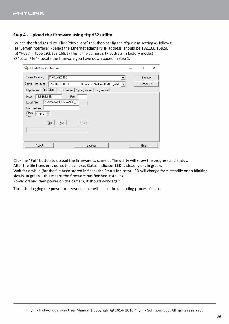
Launch the tftpd32 utility. Click “tftp client” tab, then config the tftp client setting as follows:
(a) "Server interface" - Select the Ethernet adapter’s IP address, should be 192.168.168.50
(b) "Host" - Type 192.168.168.1 (This is the camera’s IP address in factory mode.)
© "Local File" - Locate the firmware you have downloaded in step 1.
Step 4 - Upload the firmware using tftpd32 utility
Click the "Put" button to upload the firmware to camera. The utility will show the progress and status.
After the file transfer is done, the cameras Status Indicator LED is steadily on, in green.
Wait for a while (for the file been stored in flash) the Status Indicator LED will change from steadily on to blinking
slowly, in green – this means the firmware has finished installing.
Power off and then power on the camera, it should work again.
Tips: Unplugging the power or network cable will cause the uploading process failure.
| Copyright 2014- 2016 Phylink Solutions LLC. All rights reserved.Phylink Network Camera User Manual
89
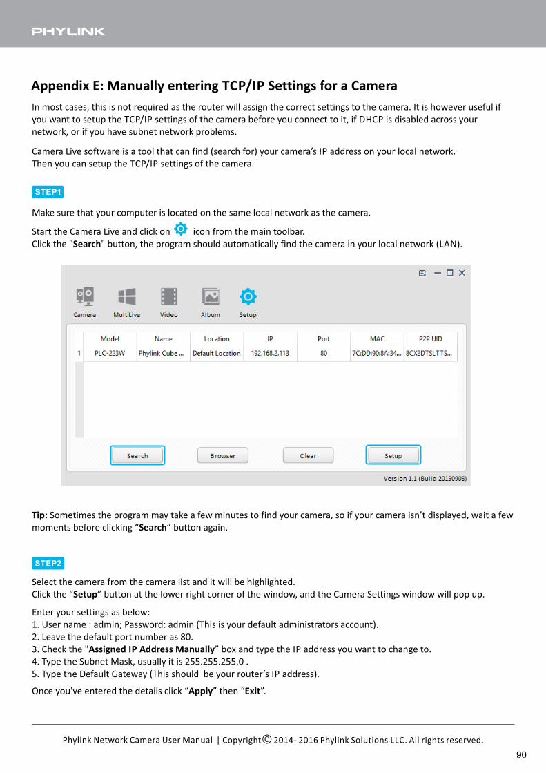
Appendix E: Manually entering TCP/IP Settings for a Camera
In most cases, this is not required as the router will assign the correct settings to the camera. It is however useful if
you want to setup the TCP/IP settings of the camera before you connect to it, if DHCP is disabled across your
network, or if you have subnet network problems.
| Copyright 2014- 2016 Phylink Solutions LLC. All rights reserved.Phylink Network Camera User Manual
Start the Camera Live and click on icon from the main toolbar.
Click the " " button, the program should automatically find the camera in your local network (LAN).Search
Tip: Sometimes the program may take a few minutes to find your camera, so if your camera isn’t displayed, wait a few
moments before clicking “ ” button again.Search
Select the camera from the camera list and it will be highlighted.
Click the “ ” button at the lower right corner of the window, and the Camera Settings window will pop up.Setup
STEP1
STEP2
Make sure that your computer is located on the same local network as the camera.
Camera Live software is a tool that can find (search for) your camera’s IP address on your local network.
Then you can setup the TCP/IP settings of the camera.
Enter your settings as below:
1. User name : admin; Password: admin (This is your default administrators account).
2. Leave the default port number as 80.
3. Check the " ” box and type the IP address you want to change to.Assigned IP Address Manually
4. Type the Subnet Mask, usually it is 255.255.255.0 .
5. Type the Default Gateway (This should be your router’s IP address).
Once you've entered the details click “ ” then “ ”.Apply Exit
90
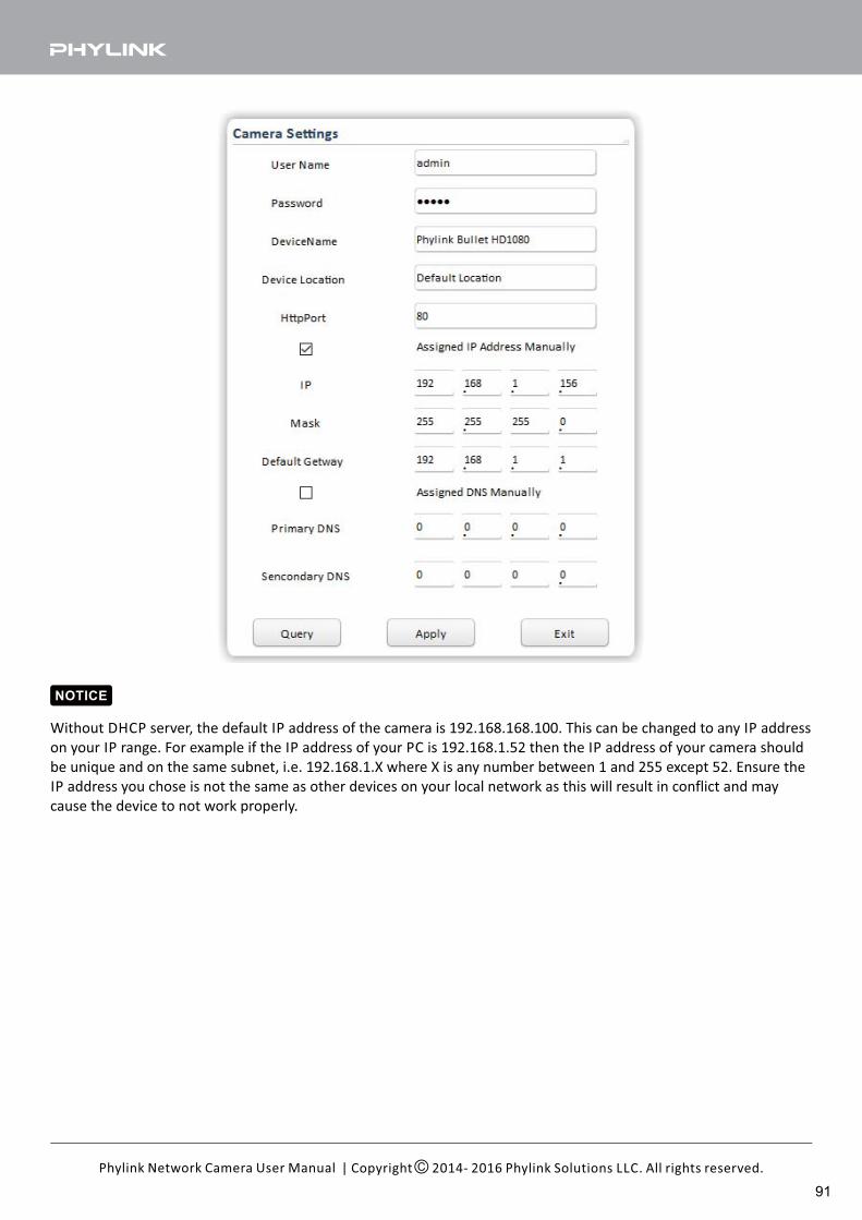
| Copyright 2014- 2016 Phylink Solutions LLC. All rights reserved.Phylink Network Camera User Manual
Without DHCP server, the default IP address of the camera is 192.168.168.100. This can be changed to any IP address
on your IP range. For example if the IP address of your PC is 192.168.1.52 then the IP address of your camera should
be unique and on the same subnet, i.e. 192.168.1.X where X is any number between 1 and 255 except 52. Ensure the
IP address you chose is not the same as other devices on your local network as this will result in conflict and may
cause the device to not work properly.
NOTICE
91
Appendix F: Wireless Installation Considerations
The wireless network camera lets you access your network using a wireless connection from anywhere within the
operating range of your wireless network. However, the number, thickness and location of walls, ceilings, or other
objects that the wireless signals must pass through, may limit the range. Typical ranges vary depending on the types
of materials and background RF (radio frequency) noise in your home or business. The key to maximizing wireless
range is to follow these basic guidelines:
1. Minimize the number of walls and ceilings between your adapter and other network devices (such as your Network
Camera) - each wall or ceiling can reduce your adapter’s range from 3-90 feet (1-30 meters).
2. Be aware of the direct line between network devices. Position your devices so that the signal will travel straight
through a wall or ceiling (instead of at an angle) for better reception.
3. Building Materials make a difference. A solid metal door or aluminum studs may weaken the wireless signal. Try to
position your wireless routers and wireless network camera where the signal passes through drywall or open
doorways.
4. Keep the wireless network camera at least 3-6 feet or 1-2 meters away from electrical devices or appliances that
generate RF noise.
5. If you are using 2.4GHz cordless phones or other radio frequency sources (such as microwave ovens), your wireless
connection may degrade dramatically or drop completely. Make sure your 2.4GHz phone base is as far away from
your wireless network camera as possible. The base transmits a signal even if the phone in not in use.
IMPORTANT!The 1080P wireless camera requires a 4 out of 5 bar or 5 out of 5 bar signal strength in the camera's system status
page for a reliable wireless connection with real-time video streaming. With a typical consumer grade router you
should expect the camera to work reliably 40 to 50 feet (12 to 15 meters) from the router, with one wall in between.
If the signal strength less than 3 out of 5 bar, you may need a Wi-Fi range extender.
| Copyright 2014- 2016 Phylink Solutions LLC. All rights reserved.Phylink Network Camera User Manual
92

| Copyright 2014- 2016 Phylink Solutions LLC. All rights reserved.Phylink Network Camera User Manual
Appendix G: Setting up the Camera over Wi-Fi using WPS
Phylink camera can be setup through a WPS connection if your router supports this function. To connect to your
camera to router through WPS connection press the WPS button located on your router and then press the WPS
button on the camera. This will establish the connection.
Note: The WPS button option should be enabled on the router for this function to work.
IMPORTANT!WPS function helps you set up your wireless easier.
But if you don't follow the instructions below carefully, you may fail.
The WPS function only work after the camera start up is completed.
After the camera is powered on, wait it start up completely . The indicator LED shows yellow light and off which
means the system is being started. When the indicator LED shows a green light again, it means the system has started
successfully.
STEP1
After the camera is powered on and start up completely, short press the Reset/WPS button on the camera and the
Status indicator LED will blink red light.
Please note that you should not press the Reset/WPS button over five seconds, otherwise the camera would be reset
instead of entering the WPS process.
STEP2
Press the WPS button on your router within two minutes. The camera will automatically create a wireless connection
to your router. While connecting, the Status indicator LED will always on and the camera will reboot.
Tips:WPS also called QSS (Quick Secure Setup) on some brands of router.
On some routers, you may need to log in to the web interface and activate the WPS feature. If you are not sure where
the WPS button is on your router, please refer to your router's user manual.
Reset/WPS Button
Status indicator LED
STEP2
93
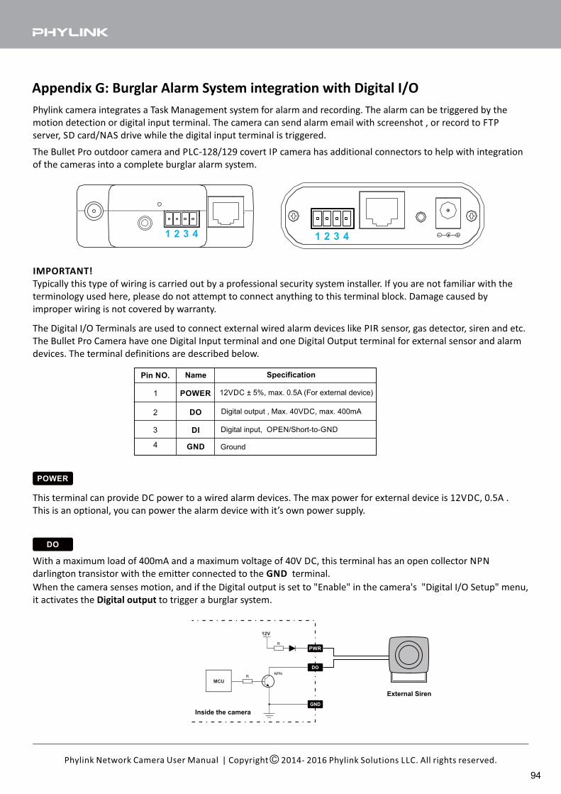
| Copyright 2014- 2016 Phylink Solutions LLC. All rights reserved.Phylink Network Camera User Manual
Appendix G: Burglar Alarm System integration with Digital I/O
Phylink camera integrates a Task Management system for alarm and recording. The alarm can be triggered by the
motion detection or digital input terminal. The camera can send alarm email with screenshot , or record to FTP
server, SD card/NAS drive while the digital input terminal is triggered.
The Digital I/O Terminals are used to connect external wired alarm devices like PIR sensor, gas detector, siren and etc.
The Bullet Pro Camera have one Digital Input terminal and one Digital Output terminal for external sensor and alarm
devices. The terminal definitions are described below.
Pin NO. Name
1
2
3
4
Specification
POWER
DI
DO
GND
12VDC ± 5%, max. 0.5A (For external device)
Digital output , Max. 40VDC, max. 400mA
Digital input, OPEN/Short-to-GND
Ground
POWER
This terminal can provide DC power to a wired alarm devices. The max power for external device is 12VDC, 0.5A .
This is an optional, you can power the alarm device with it’s own power supply.
DO
With a maximum load of 400mA and a maximum voltage of 40V DC, this terminal has an open collector NPN
darlington transistor with the emitter connected to the terminal.GND
PWR
IMPORTANT!
Typically this type of wiring is carried out by a professional security system installer. If you are not familiar with the
terminology used here, please do not attempt to connect anything to this terminal block. Damage caused by
improper wiring is not covered by warranty.
When the camera senses motion, and if the Digital output is set to "Enable" in the camera's "Digital I/O Setup" menu,
it activates the to trigger a burglar system.Digital output
Inside the camera
External Siren
1 2 3 4 1 2 3 4
The Bullet Pro outdoor camera and PLC-128/129 covert IP camera has additional connectors to help with integration
of the cameras into a complete burglar alarm system.
94
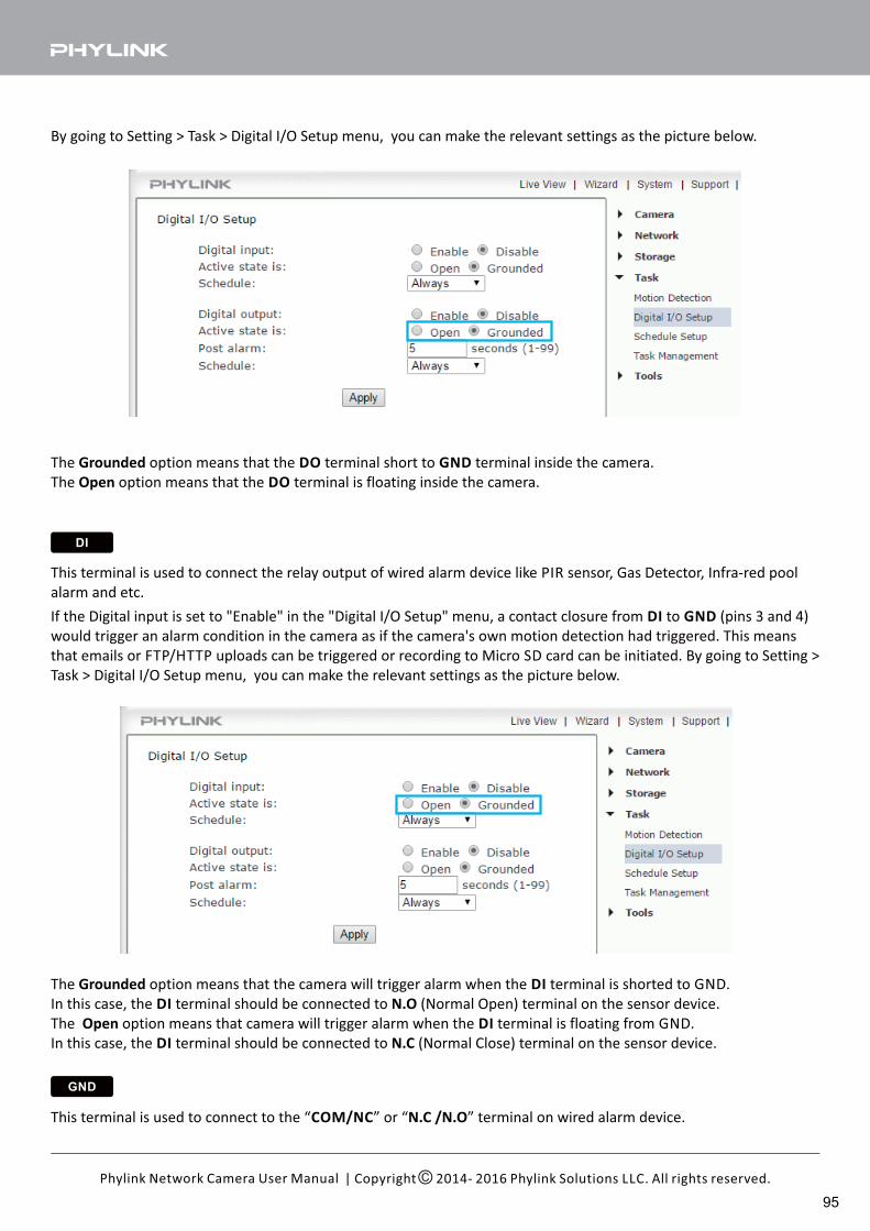
| Copyright 2014- 2016 Phylink Solutions LLC. All rights reserved.Phylink Network Camera User Manual
The option means that the terminal short to terminal inside the camera.Grounded DO GND
The option means that the terminal is floating inside the camera.Open DO
By going to Setting > Task > Digital I/O Setup menu, you can make the relevant settings as the picture below.
DI
This terminal is used to connect the relay output of wired alarm device like PIR sensor, Gas Detector, Infra-red pool
alarm and etc.
If the Digital input is set to "Enable" in the "Digital I/O Setup" menu, a contact closure from to (pins 3 and 4)DI GND
would trigger an alarm condition in the camera as if the camera's own motion detection had triggered. This means
that emails or FTP/HTTP uploads can be triggered or recording to Micro SD card can be initiated. By going to Setting >
Task > Digital I/O Setup menu, you can make the relevant settings as the picture below.
The option means that the camera will trigger alarm when the terminal is shorted to GND.Grounded DI
In this case, the terminal should be connected to (Normal Open) terminal on the sensor device.DI N.O
The option means that camera will trigger alarm when the terminal is floating from GND.Open DI
In this case, the terminal should be connected to (Normal Close) terminal on the sensor device.DI N.C
GND
This terminal is used to connect to the “ ” or “ ” terminal on wired alarm device.COM/NC N.C /N.O
95
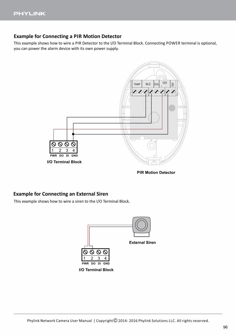
PWR DO DI GND
| Copyright 2014- 2016 Phylink Solutions LLC. All rights reserved.Phylink Network Camera User Manual
Example for Connecting a PIR Motion Detector
This example shows how to wire a PIR Detector to the I/O Terminal Block. Connecting POWER terminal is optional,
you can power the alarm device with its own power supply.
Example for Connecting an External Siren
External Siren
PWR DO DI GND
I/O Terminal Block
This example shows how to wire a siren to the I/O Terminal Block.
12VTAMP EOLN.C
PIR Motion Detector
I/O Terminal Block
96
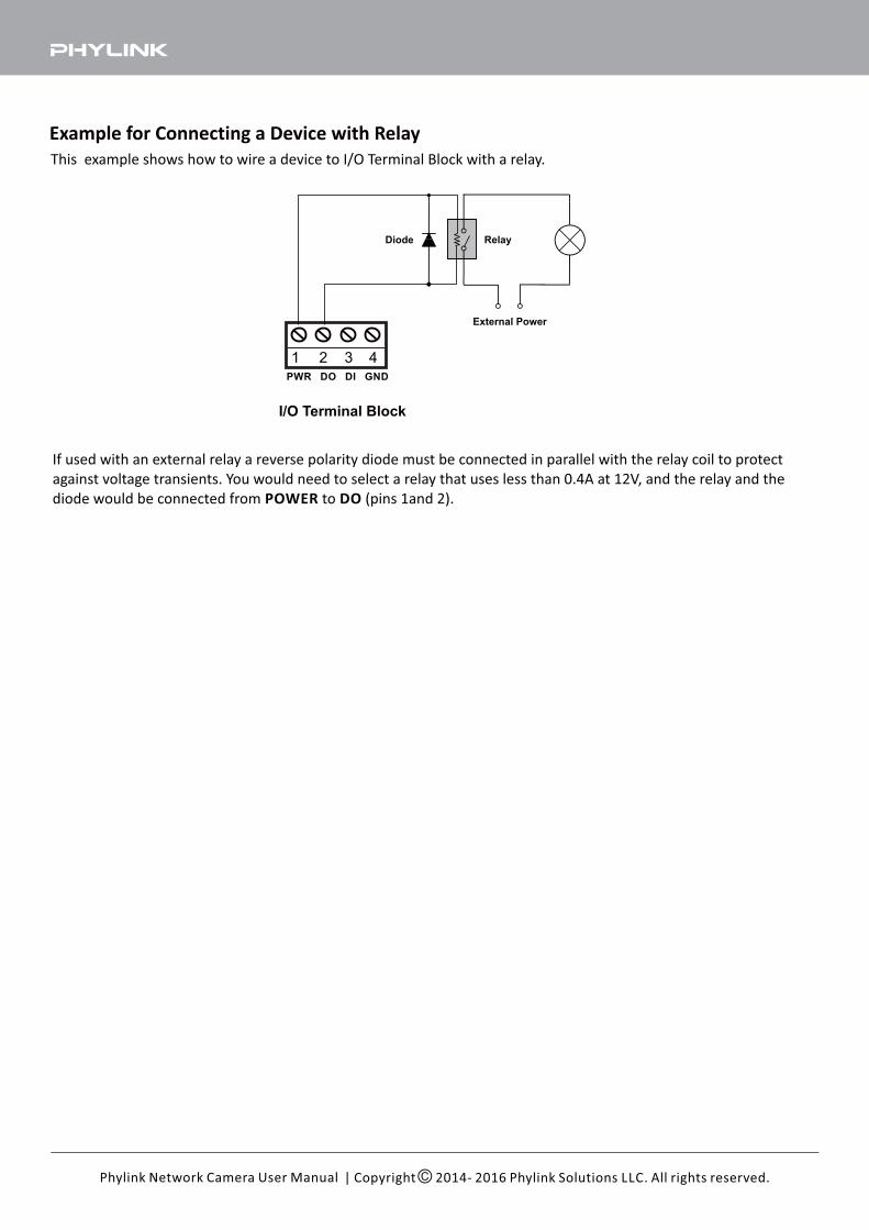
PWR DO DI GND
| Copyright 2014- 2016 Phylink Solutions LLC. All rights reserved.Phylink Network Camera User Manual
Example for Connecting a Device with Relay
This example shows how to wire a device to I/O Terminal Block with a relay.
If used with an external relay a reverse polarity diode must be connected in parallel with the relay coil to protect
against voltage transients. You would need to select a relay that uses less than 0.4A at 12V, and the relay and the
diode would be connected from to (pins 1and 2).POWER DO
Diode Relay
External Power
I/O Terminal Block
9.0 Contact Us
If you encounter any problems, do not return product to the storethe
Check for the latest updates
Can I speak to someone?
If you are totally stuck, we can make an appointment
for tech support tutorial via one-on-one telephone.
If you have any questions please email us at [email protected]
All Phylink hardware products have a one year warranty.
We offer free technical support within warranty time.
1. For the latest documentation and updates, please visit www.phylink.com.
2. New firmware versions are released periodically and they provide new features, make improvement to existing
features and fix known issues or bugs etc.
We strongly recommend you to upgrade to the latest firmware version available for your Phylink product.
To ensure that you have the most recent firmware, please visit www.phylink.com.
To learn how to update the firmware, please refer to the“ ” onHow to upgrade firmware to camera
Support - Technical Articles section from our website.
3. To ensure you have the most recent versions for the software, please visit www.phylink.com.
If you purchased this product from us or an authorized retailer,
you are eligible for priority email based technical support.
For more information or support, please visit http://www.phylink.com
For technical questions, please email us at [email protected]
You can access related technical articles on our support website
Find our support and information
Scan QR Code to get support
| Copyright 2014- 2016 Phylink Solutions LLC. All rights reserved.Phylink Network Camera User Manual
Any questions? Please send us an e-mail, we promise to deal with emails within 24 hours after receiving them. We
are always glad to help, however we ask you to read this user manual first. Find and view Technical Articles and
Troubleshooting Guide matching your problems from the support section on our support website. In most cases, the
problems you encounter will be found with answers and the corresponding solutions.
We address most support inquiries through email. One of our qualified technicians will help you as quickly as
possible. Most issues can be resolved much quicker by email than by phone. For special technical problems from
customers, email support can provide pictures, video and text points which cannot be provided by phone.
Related Documents