User Manual 4 Channel CCTV Surveillance Kit C4CHCCTVKIT V2.0

Welcome message from author
This document is posted to help you gain knowledge. Please leave a comment to let me know what you think about it! Share it to your friends and learn new things together.
Transcript
User Manual
4 Channel CCTV Surveillance Kit C4CHCCTVKIT
V2.0
2
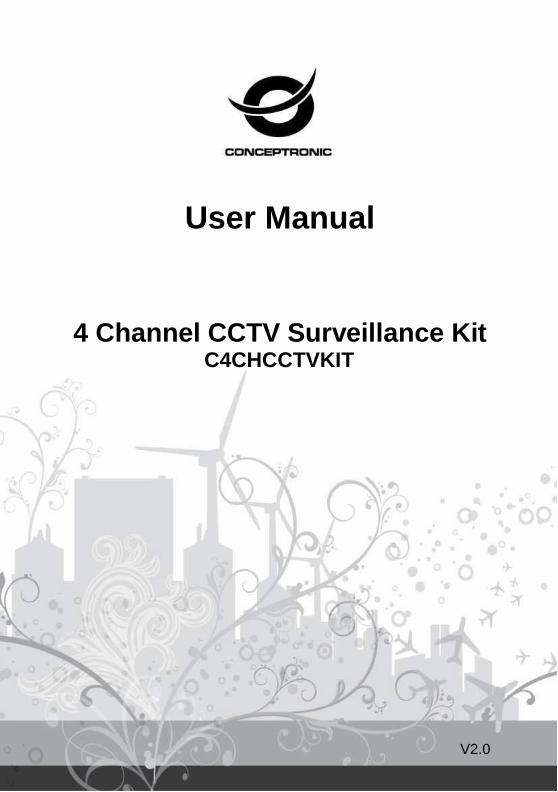
Power This DVR r e q u i r e s a DC12V adaptor; please check the power supply voltage before using the
device.
If the device is not used for an extended period of time, please turn off the power and remove the plug from the power socket;
Safety
This DVR is for indoor use only. To prevent short circuits or electrical danger, please do not position the
DVR in areas where it may come into contact with rain, or areas which have high humidity.
In instances where liquid or other material is found inside the case of the DVR, please turn off the power
immediately, and ask a qualified technician to check it before rebooting.
The DVR is a high-tech machine, and must only be serviced by a qualified technician or by returning it to the vendor.
Installation
Please ensure the DVR is installed in a level
position.
Ensure wiring and peripheral equipment is
positioned safely.
Before using the DVR for the first time, please make sure that the hard disk drive (HDD)
is correctly installed, to prevent opening the case once the machine is installed.
Select the performance of the hard disk drive (HDD) based on a rotating speed of 7200 per second.
Select an appropriate installation site, letting air flow inside the DVR, which wi l l prevent the machine
overheating.
Please do not install the DVR near a radiator, air vent or other heat source.
Direct sunlight, excessive dust and mechanical vibration can also reduce performance of the DVR.
3
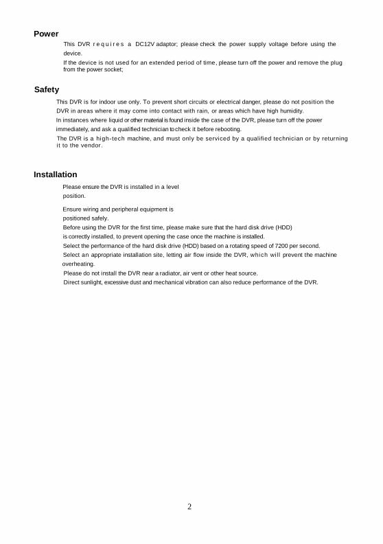
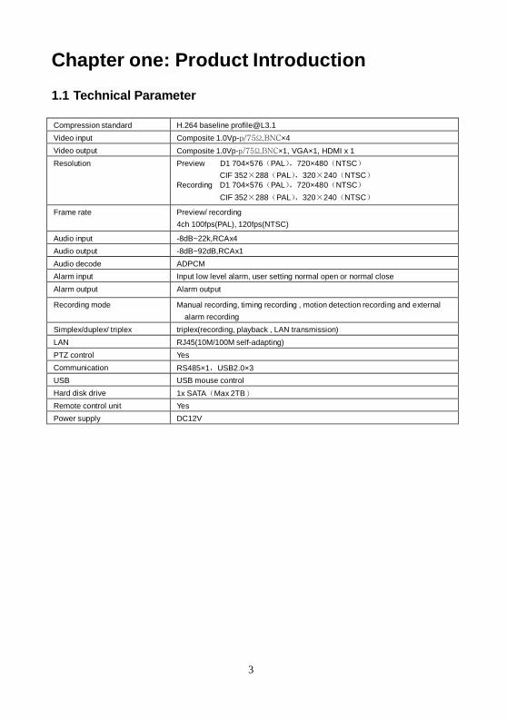
Chapter one: Product Introduction
1.1 Technical Parameter
Compression standard H.264 baseline [email protected]
Video input Composite 1.0Vp-p/75Ω,BNC×4
Video output Composite 1.0Vp-p/75Ω,BNC×1, VGA×1, HDMI x 1
Resolution Preview D1 704×576(PAL),720×480(NTSC)
CIF 352×288(PAL),320×240(NTSC)
Recording D1 704×576(PAL),720×480(NTSC)
CIF 352×288(PAL),320×240(NTSC)
Frame rate Preview/ recording
4ch 100fps(PAL), 120fps(NTSC)
Audio input -8dB~22k,RCAx4
Audio output -8dB~92dB,RCAx1
Audio decode ADPCM
Alarm input Input low level alarm, user setting normal open or normal close
Alarm output Alarm output
Recording mode Manual recording, timing recording , motion detection recording and external
alarm recording
Simplex/duplex/ triplex triplex(recording, playback , LAN transmission)
LAN RJ45(10M/100M self-adapting)
PTZ control Yes
Communication RS485×1,USB2.0×3
USB USB mouse control
Hard disk drive 1x SATA(Max 2TB)
Remote control unit Yes
Power supply DC12V
Chapter Two Hardware
2.1 H.264 standalone4 CH DVR
4 CH DVR Autonomo H.264
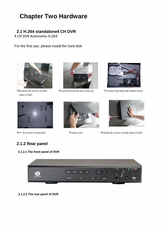
For the first use, please install the hard disk
○1 Remove the screws on both ○2 extracted from the next cover up ○3 connect hard disk and mother board
sides of shell
○4 re- fix screws to hard disk ○5 close cover ○6 install the screws on both sides of shell
2.1.2 Rear panel
2.1.2.1 The front panel of DVR
2.1.2.2 The rear panel of DVR
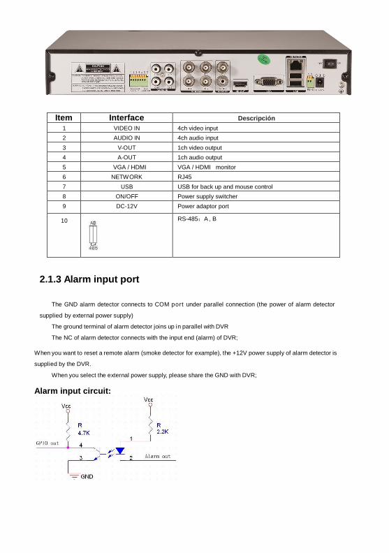
Item Interface Descripción
1 VIDEO IN 4ch video input
2 AUDIO IN 4ch audio input
3 V-OUT 1ch video output
4 A-OUT 1ch audio output
5 VGA / HDMI 2DHHHDMI
VGA / HDMI monitor
6 NETWORK RJ45
7 USB USB for back up and mouse control
8 ON/OFF Power supply switcher
9 DC-12V Power adaptor port
10
RS-485:A , B
2.1.3 Alarm input port
The GND alarm detector connects to COM port under parallel connection (the power of alarm detector
supplied by external power supply)
The ground terminal of alarm detector joins up in parallel with DVR
The NC of alarm detector connects with the input end (alarm) of DVR;
When you want to reset a remote alarm (smoke detector for example), the +12V power supply of alarm detector is
supplied by the DVR.
When you select the external power supply, please share the GND with DVR;
Alarm input circuit:
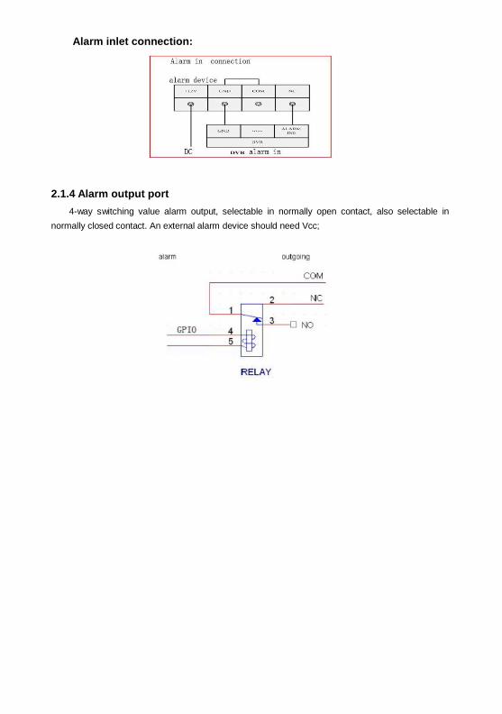
Alarm inlet connection:
2.1.4 Alarm output port
4-way switching value alarm output, selectable in normally open contact, also selectable in
normally closed contact. An external alarm device should need Vcc;
Chapter Three: Operation
3.1Operational instructions
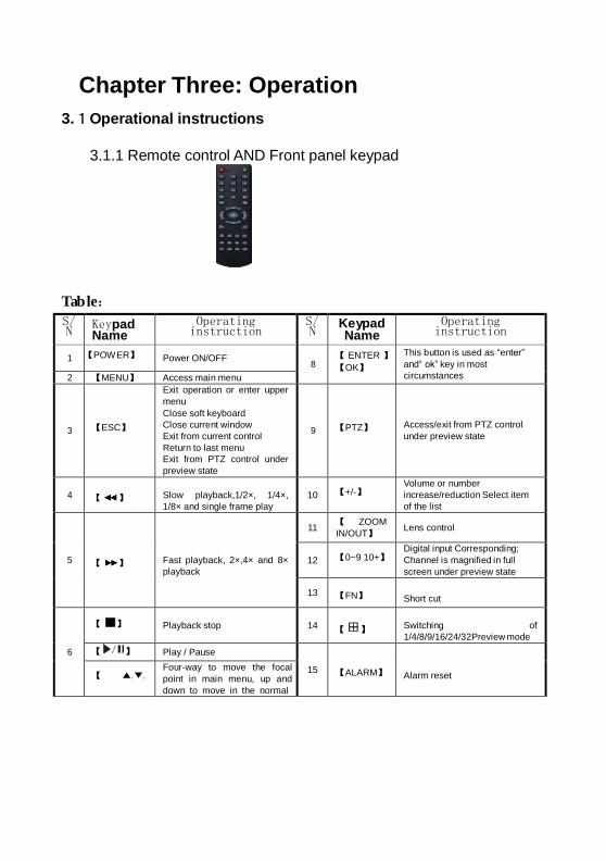
3.1.1 Remote control AND Front panel keypad
Tab le:
S/ N
Keypad Name
Operating instruction
S/ N
Keypad Name
Operating instruction
1 【POWER】
Power ON/OFF
8 【 ENTER 】
【OK】
This button is used as “enter”
and“ ok” key in most
circumstances 2 【MENU】 Access main menu
3
【ESC】
Exit operation or enter upper
menu
Close soft keyboard
Close current window
Exit from current control
Return to last menu
Exit from PTZ control under
preview state
9
【PTZ】
Access/exit from PTZ control
under preview state
4
【 】
Slow playback,1/2×, 1/4×,
1/8× and single frame play
10
【+/-】 Volume or number
increase/reduction Select item
of the list
5
【 】
Fast playback, 2×,4× and 8×
playback
11
【 ZOOM
IN/OUT】
Lens control
12
【0~9 10+】 Digital input Corresponding;
Channel is magnified in full
screen under preview state
13 【FN】
Short cut
6
【 】
Playback stop
14
【 】
Switching of
1/4/8/9/16/24/32Preview mode
【 】 Play / Pause 15
【ALARM】
Alarm reset
【 ▲.▼. Four-way to move the focal
point in main menu, up and
down to move in the normal
】 window, to control pan driver
to move in
the PTZ control windows
【REC】
To mode of recording
16
【CLEAR】
Clear alarm
7 【SEARCH】 Search for playback time
choosing
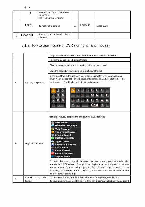
3.1.2 How to use mouse of DVR (for right hand mouse)
1
Left key single click
To go to any function menu icon click the mouse left key in the menu
To run the control, point out operation
Change again select frame or motion detection piece mode
Click the assembly frame pop-up to pull down the list
In the input frame, the user can select digit, character, lowercase, or block
letter. A left mouse click on the keyboard activates character input,with. ← for
backspace, _for blank,and Shift to switch case.
2
Right click mouse
Right click mouse, popping the shortcut menu, as follows;
Through this menu, switch between preview screen, window mode, start
replays, and PTZ control. Four pictures playback mode, the point of the right
mouse button, Can in a single picture, four pictures, eight pictures (8 road
playback), 16 screen (16 road playback),broadcast control switch view show or
hide broadcast control bar.
3
Double click left
button
To run the ActiveX Control for ActiveX special operations, double click
the recorded item as it is listed on file, then the system will playback the segment
record video.
4
Dragging the mouse
Pressing the left mouse key, drag the mouse to select a Motion detection
area, then press the right mouse key and drag to cancel the selected area.
Dragging playback Progress Bar back and forth to dolly moves, to achieve the
playback position adjustment. Dragging the audio and video regulation
parameter bar dolly moves, to achieve the parameter adjustment.
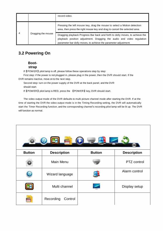
3.2 Powering On
Boot-strap
If【POWER】pilot lamp is off, please follow these operations step by step:
First step: if the power is not plugged in, please plug in the power, then the DVR should start. If the
DVR remains inactive, move on to the next step.
Second step: turn on the power supply of the DVR at the back panel, and the DVR
should start.
If【POWER】pilot lamp is RED, press the 【POWER】key, DVR should start.
The video output mode of the DVR defaults to multi picture channel mode after starting the DVR. If at the
time of starting the DVR the video output mode is in the Timing Recording setting, the DVR will automatically
start the Timer Recording function, and the corresponding channel’s recording pilot lamp will be lit up. The DVR
will function as normal.
Button Description Button Description
Main Menu
PTZ control
Wizard language
Alarm control
Multi channel
Display setup
Recording Control
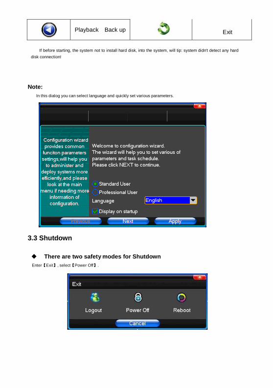
Playback Back up
Exit
If before starting, the system not to install hard disk, into the system, will tip: system didn't detect any hard
disk connection!
Note:
In this dialog you can select language and quickly set various parameters.
3.3 Shutdown
There are two safety modes for Shutdown
Enter【Exit】, select【Power Off】.

Abnormal shutdown
Through the rear panel to shutdown
When the DVR is running, please try to avoid turning the power off through the rear panel power switch (specially
while the DVR is recording).
Pulling up the power cable
While the DVR is running, please avoid pulling up the power cable as much as possible.

11
(specially while the DVR recording).
Caution: In some areas power supply may be irregular, which will cause the DVR to work abnormally, possibly
Causing damage to the unit. In this situation, please choose a stabilized voltage supply.
3.4 Multi Channel
1/4preview screen mode switch
3.5 Preview
After logging into the operating system of the DVR, system will automatically enter the preview mode.
In the preview picture, you will see the overprint date, time, and channel name. If the date and time is not shown
correctly on the picture, reset the date. There is also an alarm input mode icon. (Refer to attached table for icon
descriptions)
Channel picture attention
1
Channel is video when channel
video pictures show this symbol
2
Channel occurs when dynamic
test, channel video pictures show
this symbol
3
Channel happen when channel
video cover alarm pictures
showed this symbol
4
Channel open sound, the channel
video pictures showed this symbol
3.6 Recording operation
Customer can select the different kinds of recording mode in this system. For each different
kind of recording mode you set, the channel will show the corresponding symbol.
Manual recording
Note: Manual recording operational requirement the user should have “recording” permission.
Please make sure the hard disk drive has been installed and it has been formatted.
1)Input manual recording operation menu
Single click right key of mouse or in main menu=> recording control can move into manual recording operation menu.
12
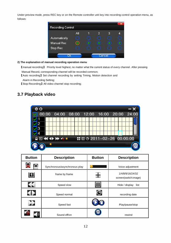
Under preview mode, press REC key or on the Remote controller unit key into recording control operation menu, as
follows:
2) The explanation of manual recording operation menu
【manual recording】 Priority level highest, no matter what the current status of every channel. After pressing
Manual Record, corresponding channel will be recorded common;
【Auto recording】Set channel recording by setting Timing, Motion detection and
Alarm in Recording Setting;
【Stop Recording】All video channel stop recording;
3.7 Playback video
Button Description Button Description
Synchronous/asynchronous play
Voice adjustment
frame by frame
1/4/8/9/16/24/32
screen(switch image)
Speed slow
Hide / display list
Speed normal
recording date
Speed fast
Play/pause/stop
Sound off/on
rewind
13
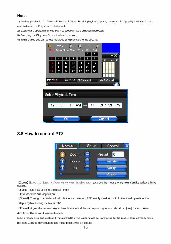
Note:
1) During playback the Playback Tool will show the file playback speed, channel, timing, playback speed etc.
information in the Playback control panel;
2) fast forward operation function can’t be selected in two channels simultaneously.
3) Can drag the Playback Speed toolbar by mouse;
4) In this dialog you can select the video time precisely to the second.
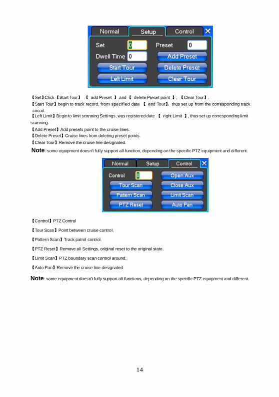
3.8 How to control PTZ
【Zoom】Moves the lens to focus on objects further away, also use the mouse wheel to undertake variable times
control.
【Focus】Slight adjusting of the focal length
【Iris】Aperture size adjustment
【Speed】Through the slider adjust rotation step interval, PTZ mainly used to control directional operation, the
step length of turning the faster PTZ.
【Preset】Adjust the camera angle, then direction and the corresponding input and click on [ set] button, preset
dots to set the dots in the preset resell.
Input presets dots and click on [Transfer] button, the camera will be transferred to the preset point corresponding
position. Click [remove] button, and these presets will be cleared
14
【Set】Click 【Start Tour】 【 add Preset 】 and 【 delete Preset point 】, 【Clear Tour】.
【Start Tour】begin to track record, from specified date 【 end Tour】,thus set up from the corresponding track
circuit.
【Left Limit】Begin to limit scanning Settings, was registered date 【 right Limit 】, thus set up corresponding limit
scanning.
【Add Preset】Add presets point to the cruise lines.
【Delete Preset】Cruise lines from deleting preset points.
【Clear Tour】Remove the cruise line designated.
Note: some equipment doesn't fully support all function, depending on the specific PTZ equipment and different.
【Control】PTZ Control
【Tour Scan】Point between cruise control.
【Pattern Scan】Track patrol control.
【PTZ Reset】Remove all Settings, original reset to the original state.
【Limit Scan】PTZ boundary scan control around.
【Auto Pan】Remove the cruise line designated
Note: some equipment doesn't fully support all functions, depending on the specific PTZ equipment and different.

15
3.9 Alarm control
【Set Alarm】Selection needs to be made in protection channel, click to confirm the corresponding channel once
protection status is chosen
【Clear Alarm】Remove protection condition, not alarm input to react
【Alarm Output】Open the alarm output. In the premise of no trigger alarm input, user can operate the output. For
example, some alarm switch is connected with a lamp; lamp is open when alarm is triggered
【All】Can choose all the channels
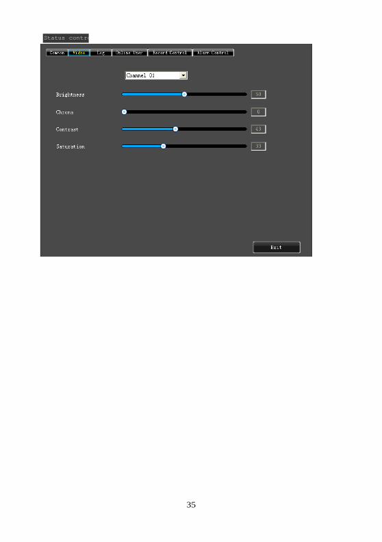
3.10 Display Adjust
(1)Video
【Video Effect】Optional: standard, sharp, custom etc
【Default】Restoring default effect, for custom video effects, copy standard effect parameters.
Through the slider, adjust brightness, contrast and saturation, tonal, etc.
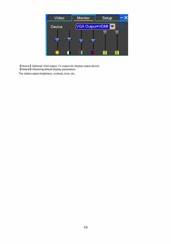
(2)Monitor
16
【Device】Optional: VGA output, TV output etc display output device.
【Default】Restoring default display parameters.
The sliders adjust brightness, contrast, tone, etc.

17
Chapter Four Menu Operation Guide
4.1 Recording Setup
(1) Recording Setup
【Channel】Choose the need to install passage "All" says setting all channels.
【Image Size】CIF/D1/960H
【Encoding Mode】Including fixed bitrate, dynamic bitrate.
【Image Quality】Client-side image quality, the higher the quality the clearer. Choice scope: minimum, low, general,
high, highest
【Frame Rate】Can click on the button manually input, 1 ~ 25 frames per second (PAL) or 1 ~ 30 frames per second
(NTSC) continuous adjustable.
【Audio】Can select close, open according to requirements
【Pre-Alarm Rec】Can select close, open according to requirements
(2)Sub-Stream
【Channel】Choose the need to install passage "ALL" says setting all channels.
【Encoding type】CIF
【Frame Rate】Including auto/1/2/3/4.
18
【Image Quality】Including lowest/low/Common/Hihg/Highest
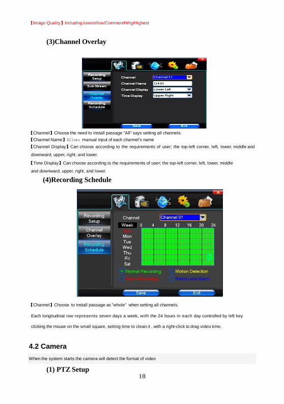
(3)Channel Overlay
【Channel】Choose the need to install passage "All" says setting all channels.
【Channel Name】Allows manual input of each channel's name
【Channel Display】Can choose according to the requirements of user; the top-left corner, left, lower, middle and
downward, upper, right, and lower.
【Time Display】Can choose according to the requirements of user; the top-left corner, left, lower, middle
and downward, upper, right, and lower.
(4)Recording Schedule
【Channel】Choose to install passage as "whole" when setting all channels.
Each longitudinal row represents seven days a week, with the 24 hours in each day controlled by left key
clicking the mouse on the small square, setting time to clean it , with a right-click to drag video time.
4.2 Camera
When the system starts the camera will detect the format of video
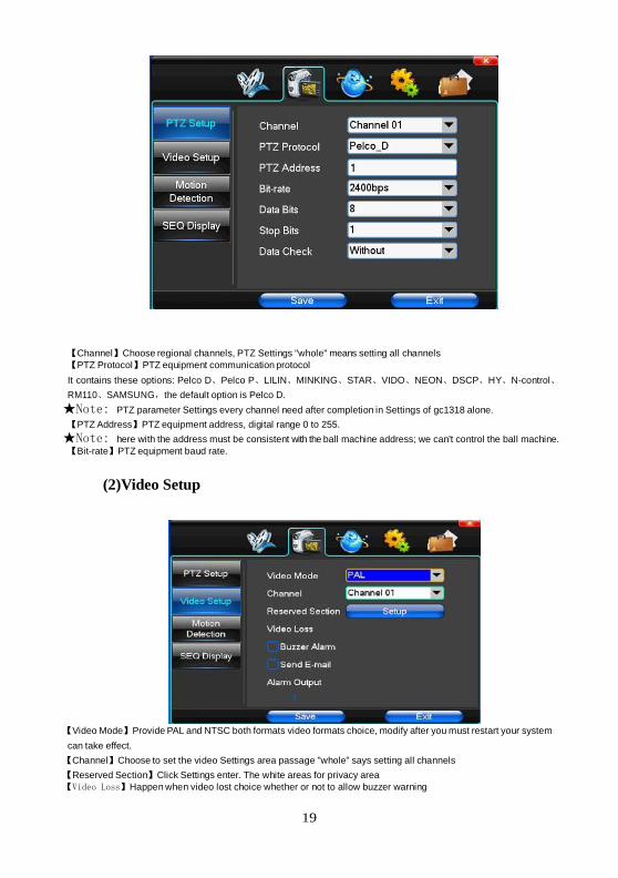
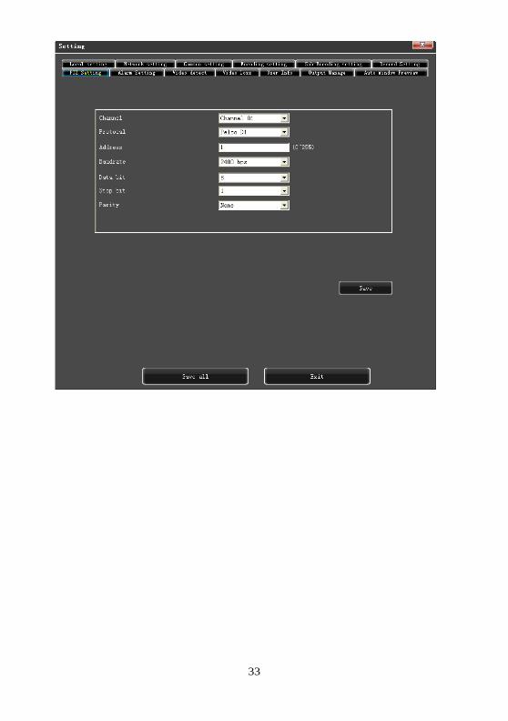
(1) PTZ Setup
19
【Channel】Choose regional channels, PTZ Settings "whole" means setting all channels
【PTZ Protocol】PTZ equipment communication protocol
It contains these options: Pelco D、Pelco P、LILIN、MINKING、STAR、VIDO、NEON、DSCP、HY、N-control、
RM110、SAMSUNG,the default option is Pelco D.
★Note: PTZ parameter Settings every channel need after completion in Settings of gc1318 alone.
【PTZ Address】PTZ equipment address, digital range 0 to 255.
★Note: here with the address must be consistent with the ball machine address; we can't control the ball machine.
【Bit-rate】PTZ equipment baud rate.
(2)Video Setup
【Video Mode】Provide PAL and NTSC both formats video formats choice, modify after you must restart your system
can take effect.
【Channel】Choose to set the video Settings area passage "whole" says setting all channels
【Reserved Section】Click Settings enter. The white areas for privacy area
【Video Loss】Happen when video lost choice whether or not to allow buzzer warning

20
【Alarm Output】Happen when video lost upcoming linkage selected channel corresponding alarm output
(3)Motion Detection
【Channel】Choose need to set up mobile testing area passage "whole" says setting all channels
【Sensitivity Setting】Can be set to give: minimum, low, general, high, highest
【Detection Area】Click Settings enter.
Green area for dynamic test, grey areas design. The brick pattern represents an undefended area. Press the mouse
left key to drag on the lower detection area to the right, press the mouse button to clear. Detection area drag The
save and exit button can save Settings, some give up and quit button abandon modification.
【Buzzer Alarm】Occurs when there is a dynamic test on the buzzer, deciding
whether to allow the alarm
【Trigger Recording】That will happen when dynamic test on the linkage of selected channel fast ball trigger video
【Alarm Output】In this passage setting user can be copied to the other channels, fulfill the same dynamic detection
alarm Settings
(4)SEQ Display
【Time】 Interval time from 5s to 255s
【Full page】 select channel to switch
【Quad page】Quad mode.
21
4.3 Network Setup
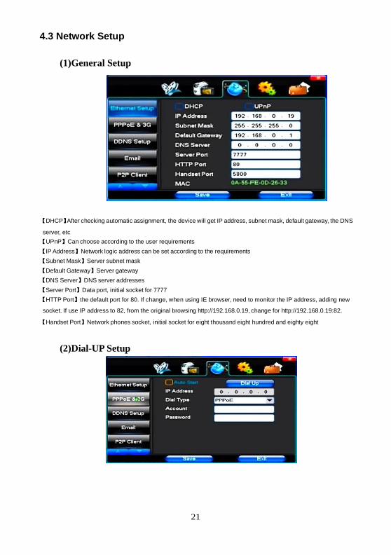
(1)General Setup
【DHCP】After checking automatic assignment, the device will get IP address, subnet mask, default gateway, the DNS
server, etc
【UPnP】Can choose according to the user requirements
【IP Address】Network logic address can be set according to the requirements
【Subnet Mask】Server subnet mask
【Default Gateway】Server gateway
【DNS Server】DNS server addresses
【Server Port】Data port, initial socket for 7777
【HTTP Port】the default port for 80. If change, when using IE browser, need to monitor the IP address, adding new
socket. If use IP address to 82, from the original browsing http://192.168.0.19, change for http://192.168.0.19:82.
【Handset Port】Network phones socket, initial socket for eight thousand eight hundred and eighty eight
(2)Dial-UP Setup
22
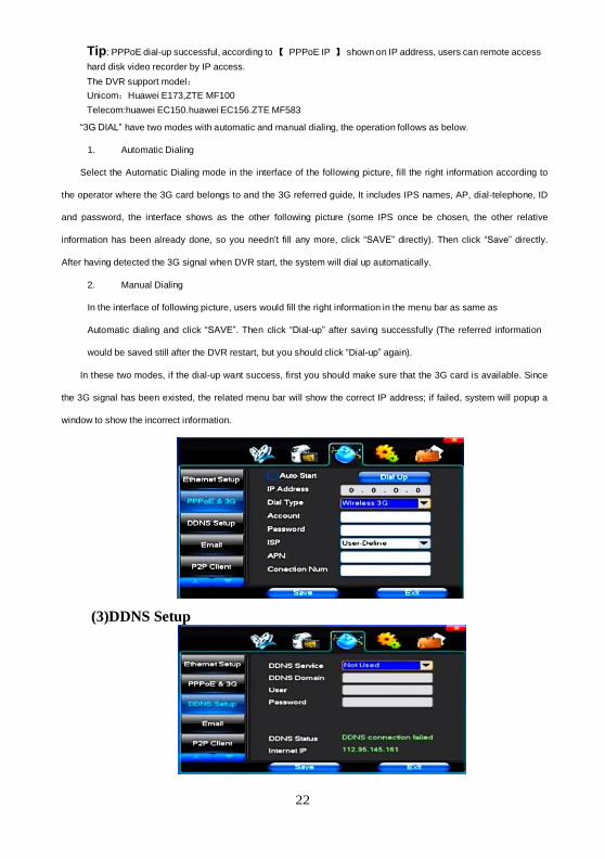
Tip: PPPoE dial-up successful, according to 【 PPPoE IP 】 shown on IP address, users can remote access
hard disk video recorder by IP access.
The DVR support model:
Unicom:Huawei E173,ZTE MF100
Telecom:huawei EC150.huawei EC156.ZTE MF583
“3G DIAL” have two modes with automatic and manual dialing, the operation follows as below.
1. Automatic Dialing
Select the Automatic Dialing mode in the interface of the following picture, fill the right information according to
the operator where the 3G card belongs to and the 3G referred guide, It includes IPS names, AP, dial-telephone, ID
and password, the interface shows as the other following picture (some IPS once be chosen, the other relative
information has been already done, so you needn’t fill any more, click “SAVE” directly). Then click “Save” directly.
After having detected the 3G signal when DVR start, the system will dial up automatically.
2. Manual Dialing
In the interface of following picture, users would fill the right information in the menu bar as same as
Automatic dialing and click “SAVE”. Then click “Dial-up” after saving successfully (The referred information
would be saved still after the DVR restart, but you should click “Dial-up” again).
In these two modes, if the dial-up want success, first you should make sure that the 3G card is available. Since
the 3G signal has been existed, the related menu bar will show the correct IP address; if failed, system will popup a
window to show the incorrect information.
(3)DDNS Setup
23
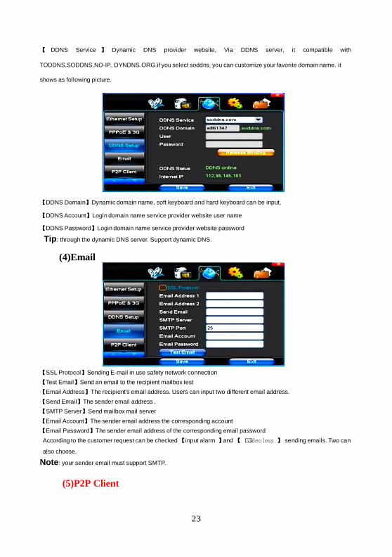
【 DDNS Service 】 Dynamic DNS provider website, Via DDNS server, it compatible with
TODDNS,SODDNS,NO-IP, DYNDNS.ORG.if you select soddns, you can customize your favorite domain name. it
shows as following picture.
【DDNS Domain】Dynamic domain name, soft keyboard and hard keyboard can be input.
【DDNS Account】Login domain name service provider website user name
【DDNS Password】Login domain name service provider website password
Tip: through the dynamic DNS server. Support dynamic DNS.
(4)Email
【SSL Protocol】Sending E-mail in use safety network connection
【Test Email】Send an email to the recipient mailbox test
【Email Address】The recipient's email address. Users can input two different email address.
【Send Email】The sender email address .
【SMTP Server】Send mailbox mail server
【Email Account】The sender email address the corresponding account
【Email Password】The sender email address of the corresponding email password
According to the customer request can be checked 【input alarm 】and 【 •video loss 】 sending emails. Two can
also choose.
Note: your sender email must support SMTP.
(5)P2P Client
24
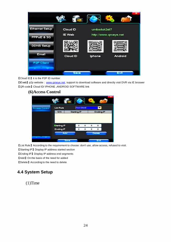
【Cloud ID】it is the P2P ID number
【IE web】p2p website : www.qmeye.net, support to download software and directly visit DVR via IE broswer
【QR-code】Cloud ID/ IPHONE ,ANDROID SOFTWARE link
(6)Access Control
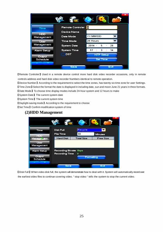
【List Rule】According to the requirement to choose: don't use, allow access, refused to visit.
【Starting IP】Display IP address started section
【Ending IP】Display IP address end segments
【Add】On the basis of the need for added
【Delete】According to the need to delete
4.4 System Setup
(1)Time
25
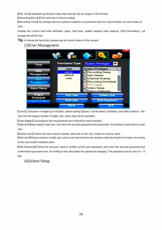
【Remote Controler】Used in a remote device control more hard disk video recorder occasions, only in remote
controls address and hard disk video recorder Numbers identical to remote operation.
【Device Number】According to the requirement to select the time zones, has twenty six time zone for user Settings.
【Time Zone】Select the format the date is displayed in including date, sun and moon June 21 years in three formats.
【Date Mode】To choose time display modes include 24-hour system and 12 hours to make
【System Date】The current system date
【System Time】The current system time
【Daylight-saving mode】According to the requirement to choose
【Set Time】Confirm modification system of time
(2)HDD Management
【Disk Full】When video disk full, the system will demonstrate how to deal with it. System will automatically record over
the earliest video files to continue covering video. " stop video " tells the system to stop the current video.
26
【File Time】automatic generation video files interval, the set range 5-120 minutes.
【Recording Bit-rate】the total rate of current coding
【Recording Time】the storage devices systems installed in accordance with the current bitrate can store video of
time.
Display the current hard disk attributes: types, hard disk, usable capacity total capacity. Click [formatting ], all
storage file will be lost.
Tip: to format the hard disk, please stop all current videos in the system.
(3)User Management
【User】Characters in length up to 8 bytes, ignore trailing Spaces. Can be letters, Numbers, and other symbols. The
user has the largest number of eight, user name may not be repeated.
【User Rights】According to the requirements set of functions need checked
【Add User】Input need to add user, and input the account password and passwords. According to save button to add
user.
【Delete User】Select the users need to delete, and click on the "yes" button to remove users
【Edit User】Choose need to modify user, and in user permissions bar needed under the function of check. According
to the save button modified users.
【Edit Password】Select the account, input to modify current user password, and enter the account password and
confirmation password new. According to the save button for password changing. The password can be set to 0 ~ 8
bits
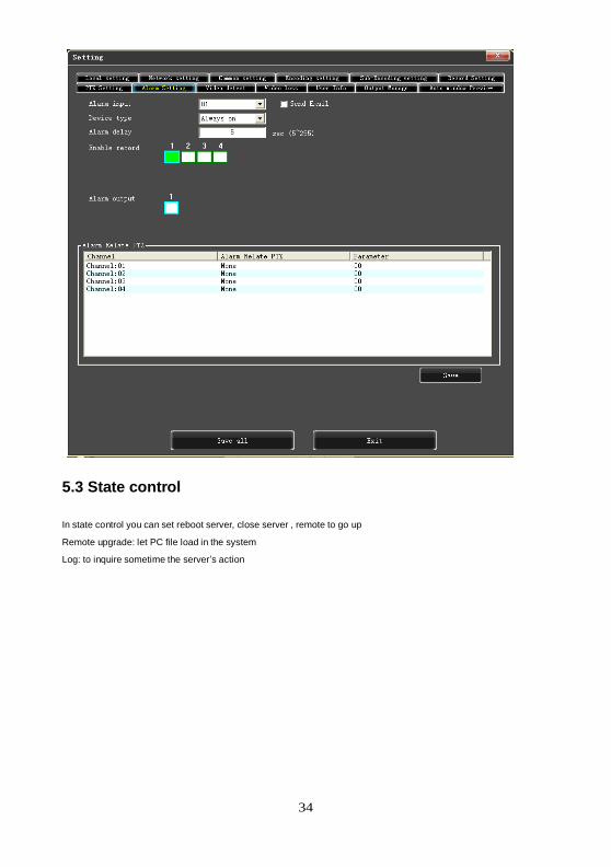
(4)Alarm Setup
27
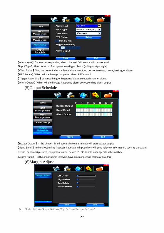
【Alarm Input】Choose corresponding alarm channel, "all" setups all channel said.
【Input Type】Alarm input to often open/closed type choice (voltage output style)
【Clear Alarm】Stop the current alarm video and alarm output, but not removal, can again trigger alarm.
【PTZ Relate】When will the linkage happened alarm PTZ control
【Trigger Recording】When will trigger happened alarm selected channel video.
【Alarm Output】When will the linkage happened alarm corresponding alarm output
(5)Output Schedule
【Buzzer Output】In the chosen time intervals have alarm input will start buzzer output.
【Send Email】In the chosen time intervals have alarm input which will send relevant information, such as the alarm
events, paparazzi pictures, equipment name, device ID, etc sent to user specifies the mailbox.
【Alarm Output】In the chosen time intervals have alarm input will start alarm output
(6)Margin Adjust
Set “Left Deflate/Right Deflate/Top Deflate/Bottom Deflate”
28
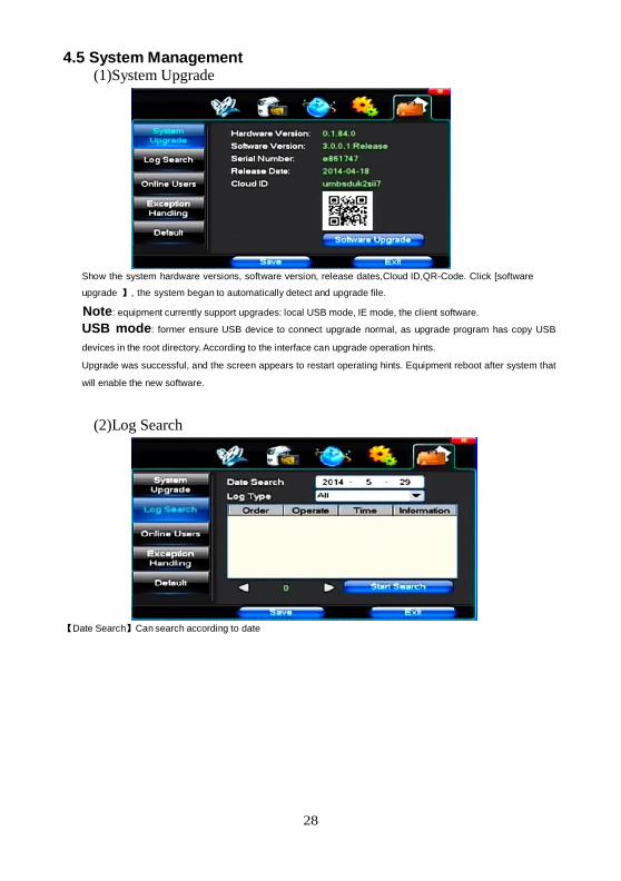
4.5 System Management (1)System Upgrade
Show the system hardware versions, software version, release dates,Cloud ID,QR-Code. Click [software
upgrade 】, the system began to automatically detect and upgrade file.
Note: equipment currently support upgrades: local USB mode, IE mode, the client software.
USB mode: former ensure USB device to connect upgrade normal, as upgrade program has copy USB
devices in the root directory. According to the interface can upgrade operation hints.
Upgrade was successful, and the screen appears to restart operating hints. Equipment reboot after system that
will enable the new software.
(2)Log Search
【Date Search】Can search according to date
29
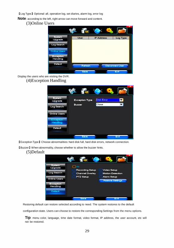
【Log Type】Optional: all, operation log, set diaries, alarm log, error log
Note: according to the left, right arrow can move forward and content. (3)Online Users
Display the users who are visiting the DVR.
(4)Exception Handling
【Exception Type】Choose abnormalities: hard disk full, hard disk errors, network connection.
【Buzzer】When abnormality, choose whether to allow the buzzer hints.
(5)Default
Restoring default can restore selected according to need. The system restores to the default
configuration state. Users can choose to restore the corresponding Settings from the menu options.
Tip: menu color, language, time date format, video format, IP address, the user account, etc will
not be restored.
30
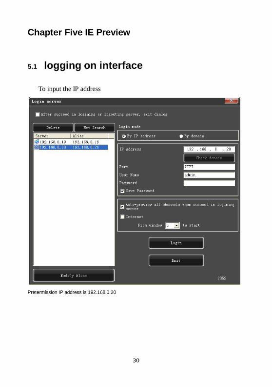
Chapter Five IE Preview
5.1 logging on interface
To input the IP address
Pretermission IP address is 192.168.0.20
31
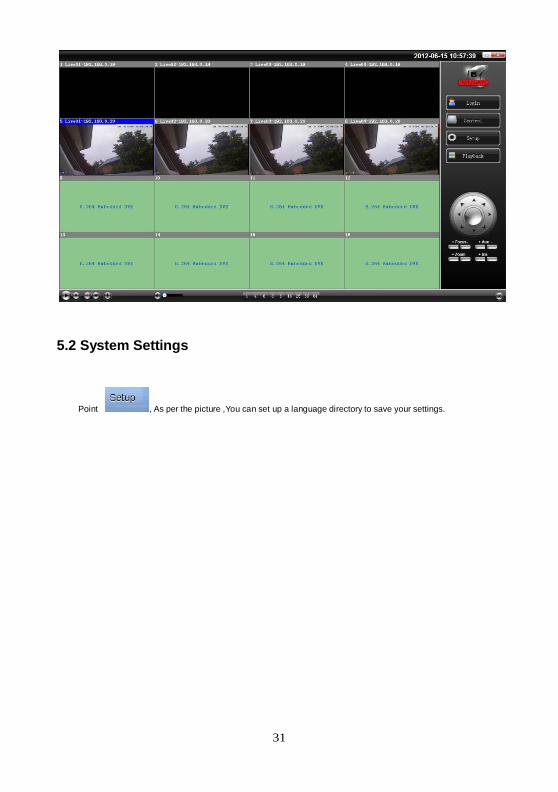
5.2 System Settings
Point , As per the picture ,You can set up a language directory to save your settings.
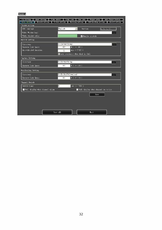
32
Sett ng
33
34
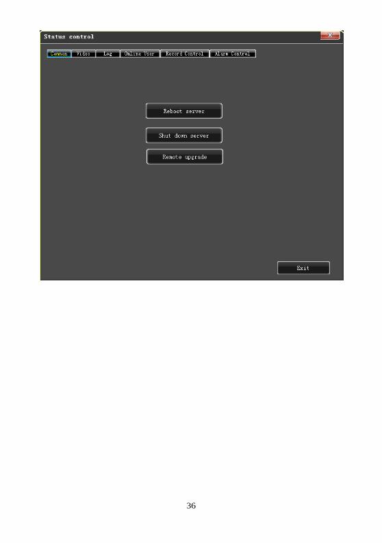
5.3 State control
In state control you can set reboot server, close server , remote to go up
Remote upgrade: let PC file load in the system
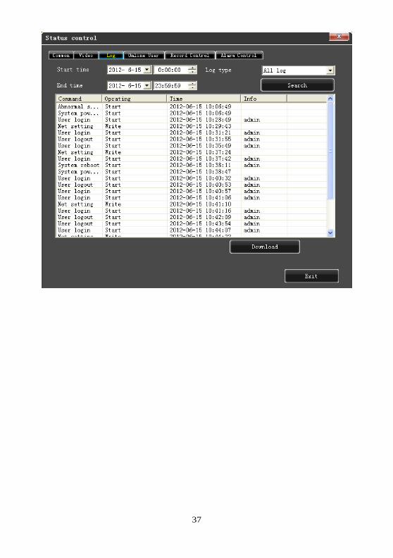
Log: to inquire sometime the server’s action
35
Status control
36
37

38
Chapter Six QMEYE phone software for use
This cloud service platform is the best mobile phone video during the internet era. It consists of front-end acquisition
devices, platform servers, and remote view of three parts.
1) The acquisition of client software:
The client software can be got from the CD material equipped with CD, then choose English and select the options
supporting tools, finally choose the mobile phone monitoring or obtained from technical support. Each type of
corresponding client software as follows.
1. QMEYE.apk: The smart phone monitoring client of Android operating system
2. QMEYE.ipa: The smart phone monitoring client of phone operating system
2) The instructions of three platforms is shown as follows.
1. android
2. iphone
6.1 Instructions of Android
6.1.1 Essential condition
1) Support the version 2.2 or above of Android system.
2) Support DVR platform versions:
Hisilicon v2.0.0.81 and higher.
6.1.2 Installation and operation instructions
Installation
Support two installation modes and the user can choose one way for installation.
1. Install online
Search QMEYE on himarket or google play and install online.
2. Install offline
Copy the QMEYE.apk installation package to Android phone through cable. In the specified directory find out the
corresponding .apk , click the application installation (If there is not installed apk installer in the mobile phone, the user
needs to download an apk installation software so that it can identify the apk package), and there will be program icons
after finishing installing.
39
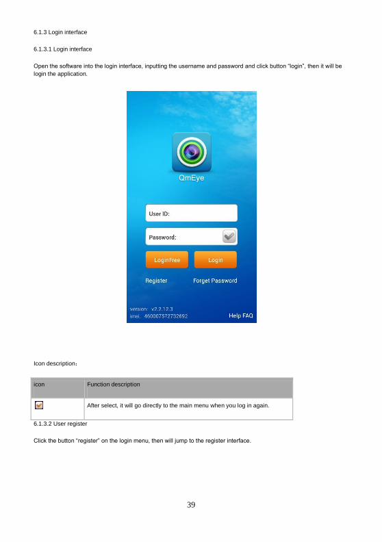
6.1.3 Login interface
6.1.3.1 Login interface
Open the software into the login interface, inputting the username and password and click button “login”, then it will be
login the application.
Icon description:
icon Function description
After select, it will go directly to the main menu when you log in again.
6.1.3.2 User register
Click the button “register” on the login menu, then will jump to the register interface.

40
Enter the register information, click “register” then will be registered.
Note: please enter the valid E-mail address in order to retrieve your password when you lost it.
6.1.3.3 Retrieve the password
On the register clicking the button “login” and jump to “retrieve password” interface.
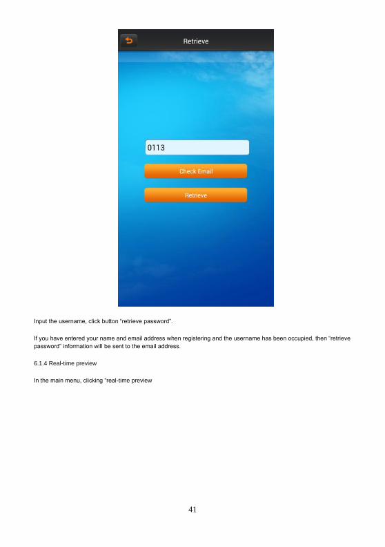
41
Input the username, click button “retrieve password”.
If you have entered your name and email address when registering and the username has been occupied, then “retrieve
password” information will be sent to the email address.
6.1.4 Real-time preview
In the main menu, clicking “real-time preview
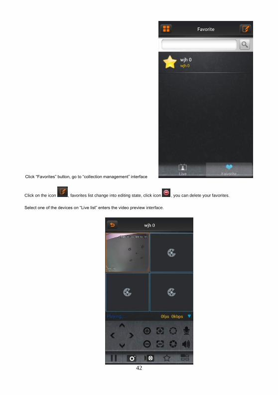
42
Click “Favorites” button, go to “collection management” interface
Click on the icon , favorites list change into editing state, click icon , you can delete your favorites.
Select one of the devices on “Live list” enters the video preview interface.
43
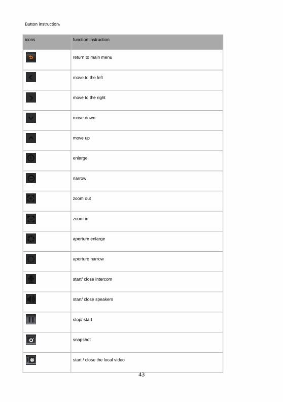
Button instruction:
icons function instruction
return to main menu
move to the left
move to the right
move down
move up
enlarge
narrow
zoom out
zoom in
aperture enlarge
aperture narrow
start/ close intercom
start/ close speakers
stop/ start
snapshot
start / close the local video
44
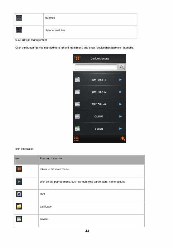
favorites
channel switcher
6.1.5 Device management
Click the button” device management” on the main menu and enter “device management” interface.
Icon instruction:
Icon Function instruction
return to the main menu
click on the pop-up menu, such as modifying parameters, name options
shot
catalogue
device
45
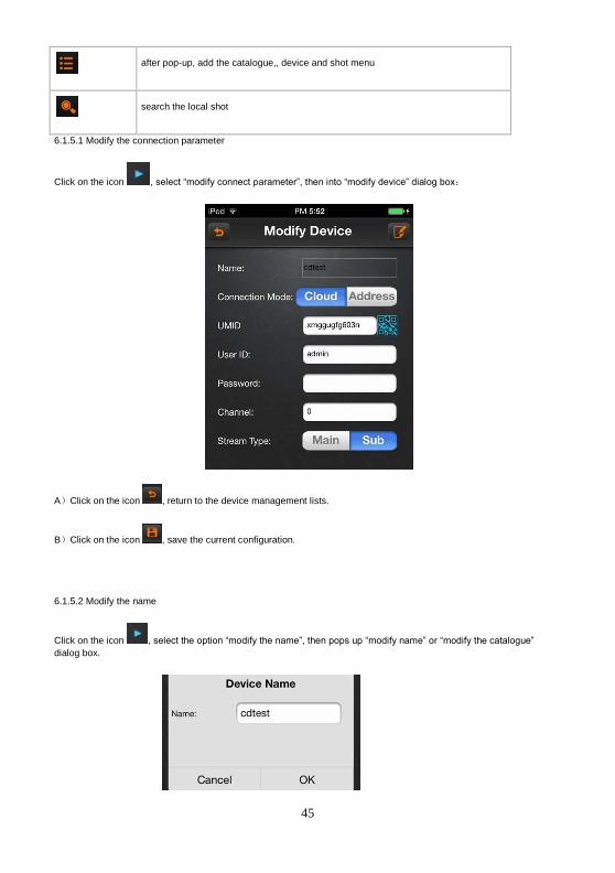
after pop-up, add the catalogue,, device and shot menu
search the local shot
6.1.5.1 Modify the connection parameter
Click on the icon , select “modify connect parameter”, then into “modify device” dialog box:
A)Click on the icon , return to the device management lists.
B)Click on the icon , save the current configuration.
6.1.5.2 Modify the name
Click on the icon , select the option “modify the name”, then pops up “modify name” or “modify the catalogue”
dialog box.
46
A)Click “OK” button to save the current configuration.
B)Click “cancel” button to cancel the modifying.
6.1.5.3 Delete
Click on icon , select “delete’ button to delete the current device directly
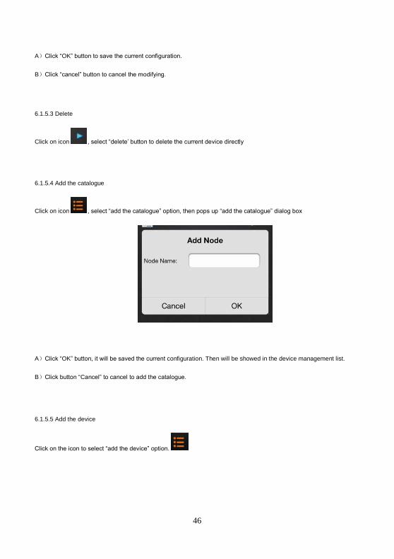
6.1.5.4 Add the catalogue
Click on icon , select “add the catalogue” option, then pops up “add the catalogue” dialog box
A)Click “OK” button, it will be saved the current configuration. Then will be showed in the device management list.
B)Click button “Cancel” to cancel to add the catalogue.
6.1.5.5 Add the device
Click on the icon to select “add the device” option.

47
Icon instruction
Icon Function instruction
Open the camera and shoot the QR code to obtain the data.
Save the device data
Cancel to add the device.
6.1.5.6 Add the shot
Please see the operation introduction of “add devices”.
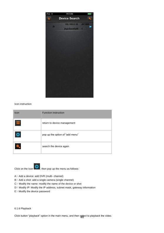
6.1.5.7 Search the local device
Click on the icon to enter “search” dialog box. If there are some devices in local place, you would search out the
corresponding device.
48
Icon instruction
Icon Function instruction
return to device management
pop up the option of “add menu”
search the device again
Click on the icon , then pop up the menu as follows:
A)Add a device: add DVR (multi- channel)
B)Add a shot: add a single camera (single channel)
C)Modify the name: modify the name of the device or shot
D)Modify IP: Modify the IP address, subnet mask, gateway information
E)Modify the device password
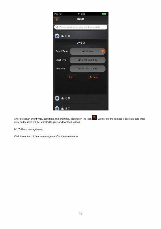
6.1.6 Playback
Click button “playback” option in the main menu, and then select to playback the video.
49
After select an event type, start time and end time, clicking on the icon will list out the remote video lists, and then
click on the item will be selected to play or download videos.
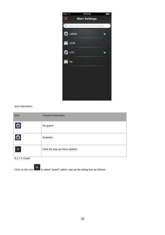
6.1.7 Alarm management
Click the option of “alarm management” in the main menu
50
Icon instruction:
Icon Function instruction
No guard
Guarded
Click the pop-up menu options
6.1.7.1 Guard
Click on the icon to select “guard” option, pop up the dialog box as follows:
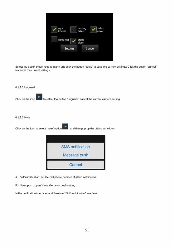
51
Select the option those need to alarm and click the button “setup” to save the current settings; Click the button “cancel”
to cancel the current settings.
6.1.7.2 Unguard
Click on the icon to select the button “unguard”, cancel the current camera setting.
6.1.7.3 Note
Click on the icon to select “note” option , and then pop up the dialog as follows:
A)SMS notification: set the cell phone number of alarm notification
B)News push: open/ close the news push setting
In the notification interface, and then into “SMS notification” interface
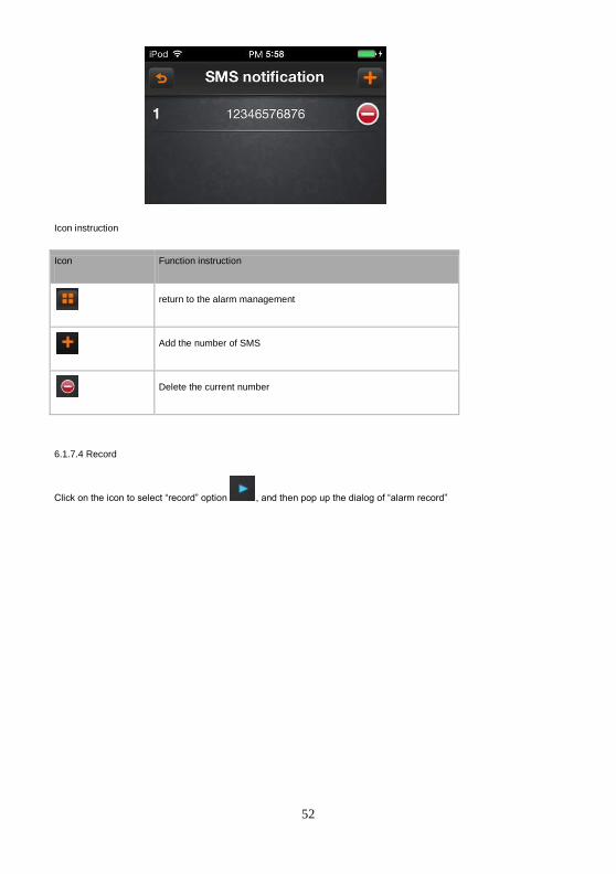
52
Icon instruction
Icon Function instruction
return to the alarm management
Add the number of SMS
Delete the current number
6.1.7.4 Record
Click on the icon to select “record” option , and then pop up the dialog of “alarm record”
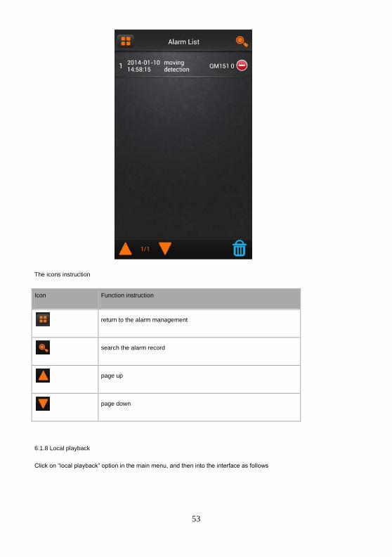
53
The icons instruction
Icon Function instruction
return to the alarm management
search the alarm record
page up
page down
6.1.8 Local playback
Click on “local playback” option in the main menu, and then into the interface as follows
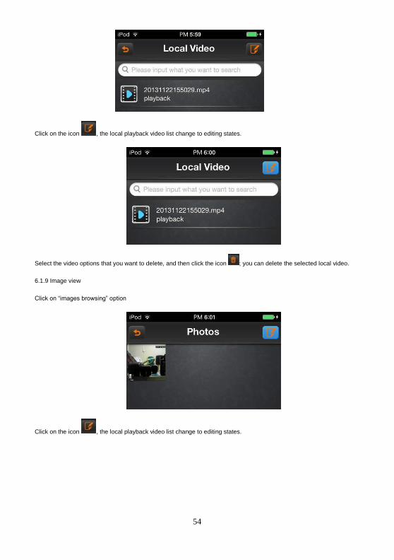
54
Click on the icon , the local playback video list change to editing states.
Select the video options that you want to delete, and then click the icon ; you can delete the selected local video.
6.1.9 Image view
Click on “images browsing” option
Click on the icon , the local playback video list change to editing states.
55
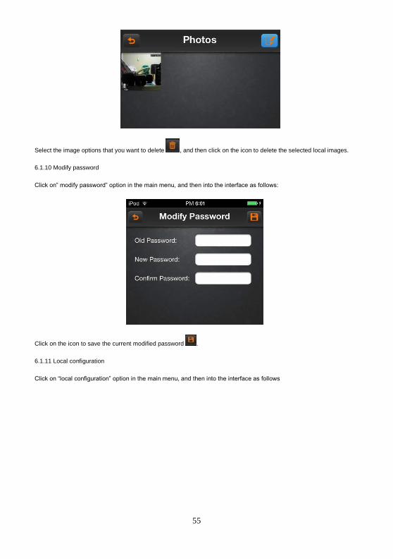
Select the image options that you want to delete , and then click on the icon to delete the selected local images.
6.1.10 Modify password
Click on” modify password” option in the main menu, and then into the interface as follows:
Click on the icon to save the current modified password .
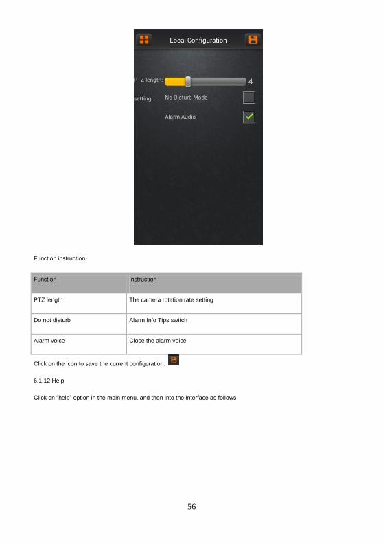
6.1.11 Local configuration
Click on “local configuration” option in the main menu, and then into the interface as follows
56
Function instruction:
Function Instruction
PTZ length The camera rotation rate setting
Do not disturb Alarm Info Tips switch
Alarm voice Close the alarm voice
Click on the icon to save the current configuration.
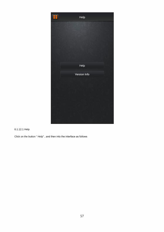
6.1.12 Help
Click on “help” option in the main menu, and then into the interface as follows
57
6.1.12.1 Help
Click on the button “ Help” , and then into the interface as follows

58
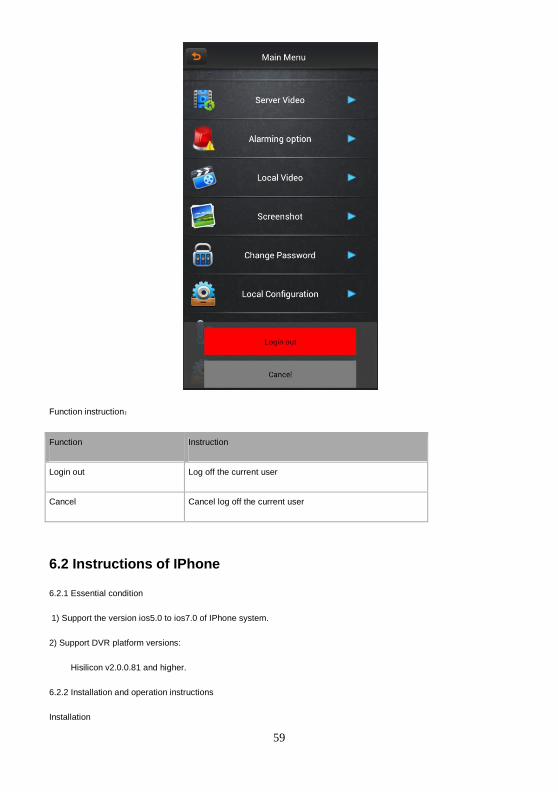
6.1.12 Login out
Click on “login out” option in the main menu, and then into the interface as follows
59
Function instruction:
Function Instruction
Login out Log off the current user
Cancel Cancel log off the current user
6.2 Instructions of IPhone
6.2.1 Essential condition
1) Support the version ios5.0 to ios7.0 of IPhone system.
2) Support DVR platform versions:
Hisilicon v2.0.0.81 and higher.
6.2.2 Installation and operation instructions
Installation
60
Support two installation modes and the user can choose one way for installation.
1. Install online
Run the App Store program of iPhone.
Switch to the search tag page, and input QMEYE in the search box to find the application installation package, then click
<install> .After finishing installation, there will be QMEYE program icon on the mobile phone desktop.
2. Install offline
Copy the QMEYE.ipa installation package to Iphone mobile through cable. In the specified directory find out the
corresponding .ipa, click the application installation, and there will be program icons after finishing installing.
6.2.3 Login register
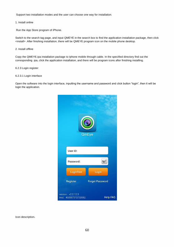
6.2.3.1 Login interface
Open the software into the login interface, inputting the username and password and click button “login”, then it will be
login the application.
Icon description:

61
icon Function description
After select, it will go directly to the main menu when you log in again.
6.2.3.2 User register
Click the button “register” on the login menu, then will jump to the register interface.
Enter the register information, click “register” then will be registered.
Note: please enter the valid E-mail address in order to retrieve your password when you lost it.
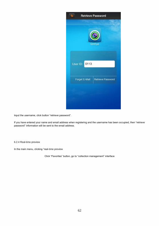
6.2.3.3 Retrieve the password
On the register clicking the button “login” and jump to “Retrieve password” interface.
62
Input the username, click button “retrieve password”.
If you have entered your name and email address when registering and the username has been occupied, then “retrieve
password” information will be sent to the email address.
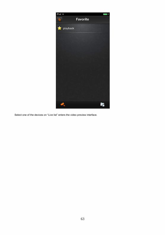
6.2.4 Real-time preview
In the main menu, clicking “real-time preview
Click “Favorites” button, go to “collection management” interface
63
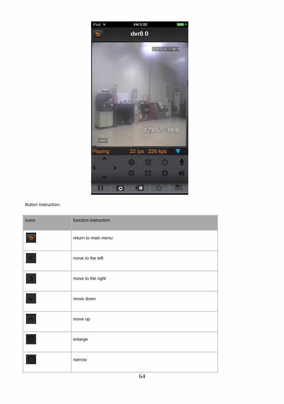
Select one of the devices on “Live list” enters the video preview interface.
64
Button instruction:
icons function instruction
return to main menu
move to the left
move to the right
move down
move up
enlarge
narrow

65
zoom out
zoom in
aperture enlarge
aperture narrow
start/ close intercom
start/ close speakers
stop/ start
snapshot
start / close the local video
favorites
channel switcher
6.2.5 Device management
Click the button” device management” on the main menu and enter “device management” interface.

66
Icon instruction:
Icon Function instruction
return to the main menu
click on the pop-up menu, such as modifying parameters, name options
shot
catalogue
device
after pop-up, add the catalogue,, device and shot menu
search the local shot
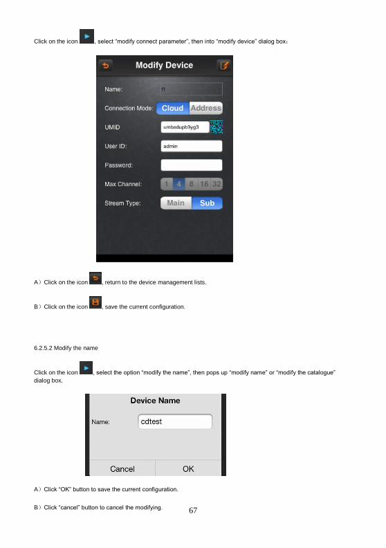
6.2.5.1 Modify the connection parameter
67
Click on the icon , select “modify connect parameter”, then into “modify device” dialog box:
A)Click on the icon , return to the device management lists.
B)Click on the icon , save the current configuration.
6.2.5.2 Modify the name
Click on the icon , select the option “modify the name”, then pops up “modify name” or “modify the catalogue”
dialog box.
A)Click “OK” button to save the current configuration.
B)Click “cancel” button to cancel the modifying.

68
6.2.5.3 Delete
Click on icon , select “delete’ button to delete the current device directly
6.2.5.4 Add the catalogue
Click on icon , select “add the catalogue” option, then pops up “add the catalogue” dialog box
A)Click “OK” button, it will be saved the current configuration. Then will be showed in the device management list.
B)Click button “Cancel” to cancel to add the catalogue.
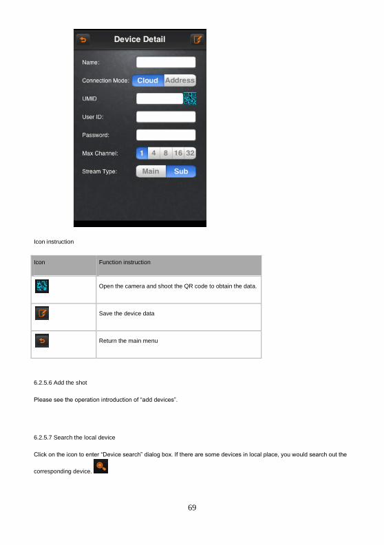
6.2.5.5 Add the device
Click on the icon to select “add the device” option.
69
Icon instruction
Icon Function instruction
Open the camera and shoot the QR code to obtain the data.
Save the device data
Return the main menu
6.2.5.6 Add the shot
Please see the operation introduction of “add devices”.
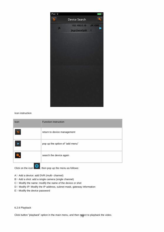
6.2.5.7 Search the local device
Click on the icon to enter “Device search” dialog box. If there are some devices in local place, you would search out the
corresponding device.
70
Icon instruction
Icon Function instruction
return to device management
pop up the option of “add menu”
search the device again
Click on the icon , then pop up the menu as follows:
A)Add a device: add DVR (multi- channel)
B)Add a shot: add a single camera (single channel)
C)Modify the name: modify the name of the device or shot
D)Modify IP: Modify the IP address, subnet mask, gateway information
E)Modify the device password
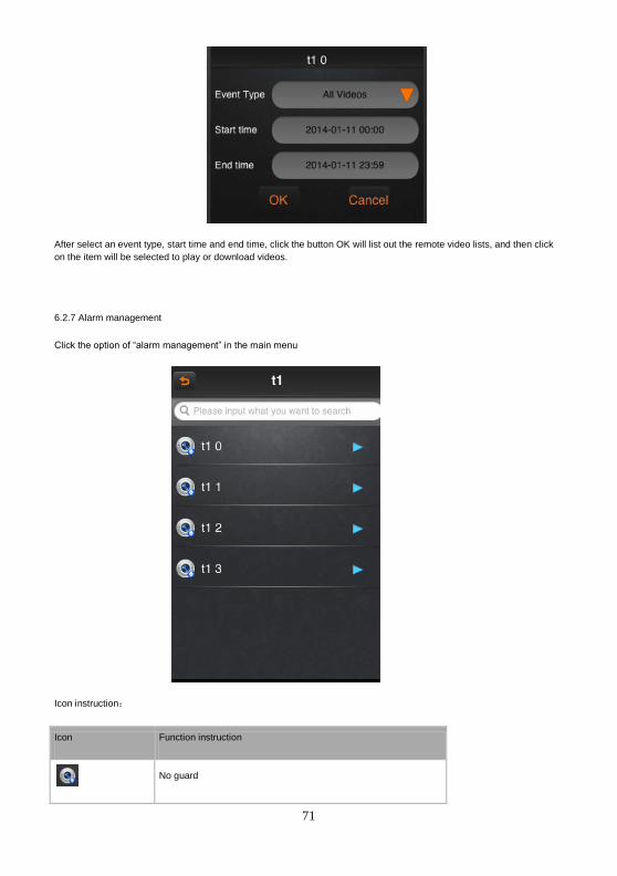
6.2.6 Playback
Click button “playback” option in the main menu, and then select to playback the video.
71
After select an event type, start time and end time, click the button OK will list out the remote video lists, and then click
on the item will be selected to play or download videos.
6.2.7 Alarm management
Click the option of “alarm management” in the main menu
Icon instruction:
Icon Function instruction
No guard
72
Guarded
Click the pop-up menu options
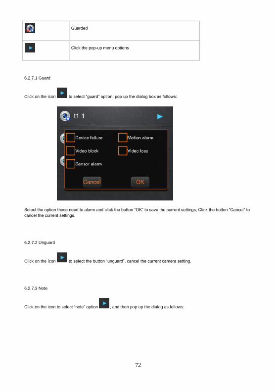
6.2.7.1 Guard
Click on the icon to select “guard” option, pop up the dialog box as follows:
Select the option those need to alarm and click the button “OK” to save the current settings; Click the button “Cancel” to
cancel the current settings.
6.2.7.2 Unguard
Click on the icon to select the button “unguard”, cancel the current camera setting.
6.2.7.3 Note
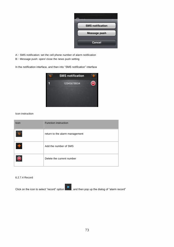
Click on the icon to select “note” option , and then pop up the dialog as follows:
73
A)SMS notification: set the cell phone number of alarm notification
B)Message push: open/ close the news push setting
In the notification interface, and then into “SMS notification” interface
Icon instruction
Icon Function instruction
return to the alarm management
Add the number of SMS
Delete the current number
6.2.7.4 Record
Click on the icon to select “record” option , and then pop up the dialog of “alarm record”

74
The icons instruction
Icon Function instruction
return to the alarm management
search the alarm record
page up
page down
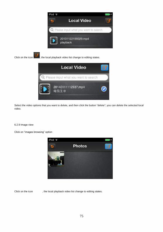
6.2.8 Local playback
Click on “local playback” option in the main menu, and then into the interface as follows
75
Click on the icon , the local playback video list change to editing states.
Select the video options that you want to delete, and then click the button "delete"; you can delete the selected local
video.
6.2.9 Image view
Click on “images browsing” option
Click on the icon , the local playback video list change to editing states.
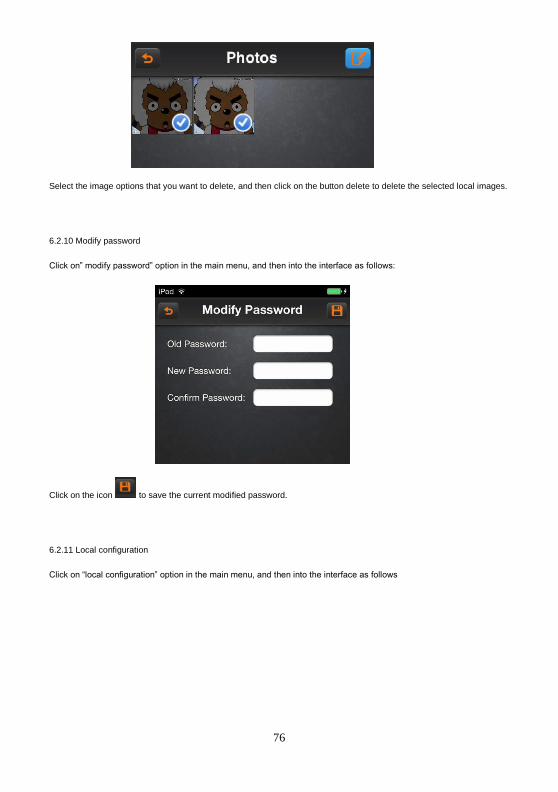
76
Select the image options that you want to delete, and then click on the button delete to delete the selected local images.
6.2.10 Modify password
Click on” modify password” option in the main menu, and then into the interface as follows:
Click on the icon to save the current modified password.
6.2.11 Local configuration
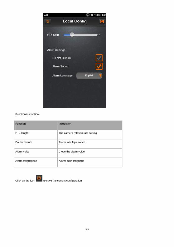
Click on “local configuration” option in the main menu, and then into the interface as follows
77
Function instruction:
Function Instruction
PTZ length The camera rotation rate setting
Do not disturb Alarm Info Tips switch
Alarm voice Close the alarm voice
Alarm languagece Alarm push language
Click on the icon to save the current configuration.
78
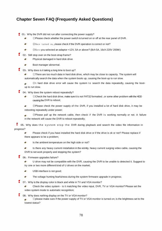
Chapter Seven FAQ (Frequently Asked Questions)
01:Why the DVR did not run after connecting the power supply?
①Please check whether the power switch is turned on or off at the rear panel of DVR.
②Once turned on,please check if the DVR operation is correct or not?
③Have you selected an adaptor +12V, 5A or above? (8ch 5A, 16ch 220V 200W)
02:Still stop over on the boot-strap frame?
Physical damaged in hard disk drive
Boot manager abnormal.
03:Why does is it taking a long time to boot up?
①There are too much data in hard disk drive, which may be close to capacity. The system will
automatically search the data when the system boots up, causing the boot-up to run slow.
②A hard disk drive error will cause the system t o search the data repeatedly, causing the boot-
up to run slow.
04:Why does the system reboot repeatedly?
①Check the hard disk drive, make sure it is not FAT32 formatted , or some other problem with the HDD
causing the DVR to reboot;
②Please check the power supply of the DVR, if you installed a lot of hard disk drive, it may be
rebooting repeatedly under power;
③Please pull up the network cable, then check i f the DVR i s working normally or not. A failure
in the network will cause the DVR to reboot repeatedly;
05:Why does t h e s y s t e m s t o p t h e DVR during playback and search the video file information in
progress?
Please check if you have installed the hard disk drive or if the drive is ok or not? Please replace if
there appears to be a problem;
Is the ambient temperature on the high side or not?
Is there any heavy current installation in the vicinity, heavy current surging video cable, causing the
DVR to not work properly and stopping the system?
06:Firmware upgrades failure?
U drive may not be compatible with the DVR, causing the DVR to be unable to detected it. Suggest to
try one or two more different kind of U drives on the market;
USB interface is not good;
The voltage hunting fearfulness during the system firmware upgrade in progress;
07:Why is the display color is black and white in TV and VGA monitor?
Check the video system - is it matching the video input, DVR, TV or VGA monitor? Please set the
video system mode to automatic recognition;
08:Why does nothing display on the TV or VGA monitor?
①please make sure if the power supply of TV or VGA monitor is turned on; is the brightness set to the
lowest status?
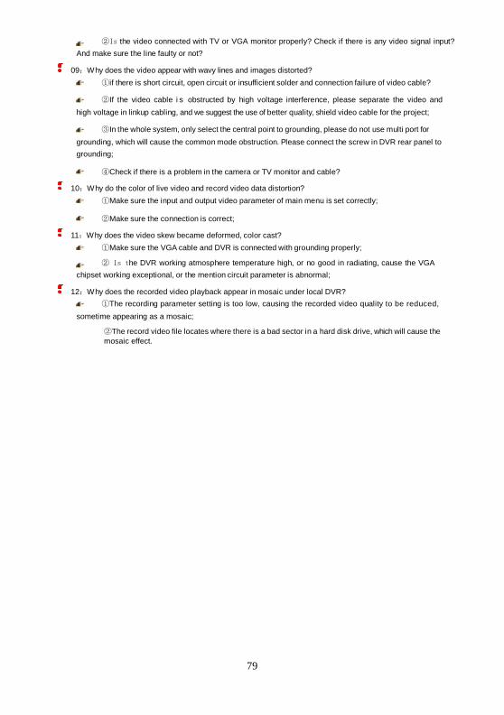
79
②Is the video connected with TV or VGA monitor properly? Check if there is any video signal input?
And make sure the line faulty or not?
09:Why does the video appear with wavy lines and images distorted?
①if there is short circuit, open circuit or insufficient solder and connection failure of video cable?
②If the video cable i s obstructed by high voltage interference, please separate the video and
high voltage in linkup cabling, and we suggest the use of better quality, shield video cable for the project;
③In the whole system, only select the central point to grounding, please do not use multi port for
grounding, which will cause the common mode obstruction. Please connect the screw in DVR rear panel to
grounding;
④Check if there is a problem in the camera or TV monitor and cable?
10:Why do the color of live video and record video data distortion?
①Make sure the input and output video parameter of main menu is set correctly;
②Make sure the connection is correct;
11:Why does the video skew became deformed, color cast?
①Make sure the VGA cable and DVR is connected with grounding properly;
② Is the DVR working atmosphere temperature high, or no good in radiating, cause the VGA
chipset working exceptional, or the mention circuit parameter is abnormal;
12:Why does the recorded video playback appear in mosaic under local DVR?
①The recording parameter setting is too low, causing the recorded video quality to be reduced,
sometime appearing as a mosaic;
②The record video file locates where there is a bad sector in a hard disk drive, which will cause the
mosaic effect.
80
Notification of Compliance
Appendix A
Europe - EU Declaration of Conformity
For complete DoC please visit
http://www.conceptronic.net/download.php
GPL License Agreement
GPL may be included in this product, to view the GPL license agreement goes to
http://download.conceptronic.net/GPL/GPL.pdf
For GNU General Public License (GPL) related information, please visit
http://www.conceptronic.net/download.php
Related Documents