High Efficiency Solutions SmartCella/SmartCella 3PH NO POWER & SIGNAL CABLES TOGETHER READ CAREFULLY IN THE TEXT! Electronic controllers for cold rooms User manual

Welcome message from author
This document is posted to help you gain knowledge. Please leave a comment to let me know what you think about it! Share it to your friends and learn new things together.
Transcript
H i g h E f f i c i e n c y S o l u t i o n s
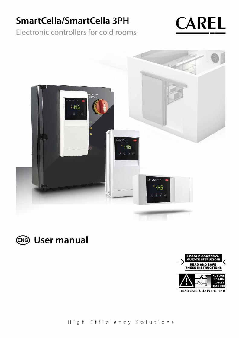
SmartCella/SmartCella 3PH
NO POWER& SIGNAL CABLES
TOGETHER
READ CAREFULLY IN THE TEXT!
Electronic controllers for cold rooms
User manual

3
ENG
“SmartCella manual” +0300084EN - rel. 1.3 - 24.09.2020
WARNING
CAREL bases the development of its products on decades of experience in
HVAC, on the continuous investments in technological innovations to products,
procedures and strict quality processes with in-circuit and functional testing on
100% of its products, and on the most innovative production technology available
on the market. CAREL and its subsidiaries nonetheless cannot guarantee that all
the aspects of the product and the software included with the product respond
to the requirements of the fi nal application, despite the product being developed
according to start-of-the-art techniques.
The customer (manufacturer, developer or installer of the fi nal equipment) accepts
all liability and risk relating to the confi guration of the product in order to reach
the expected results in relation to the specifi c fi nal installation and/or equipment.
CAREL may, based on specifi c agreements, act as a consultant for the positive
commissioning of the fi nal unit/application, however in no case does it accept
liability for the correct operation of the fi nal equipment/system.
The CAREL product is a state-of-the-art product, whose operation is specifi ed in the
technical documentation supplied with the product or can be downloaded, even
prior to purchase, from the website www.CAREL.com.
Each CAREL product, in relation to its advanced level of technology, requires setup
/ confi guration / programming / commissioning to be able to operate in the best
possible way for the specifi c application. The failure to complete such operations,
which are required/indicated in the user manual, may cause the fi nal product to
malfunction; CAREL accepts no liability in such cases.
Only qualifi ed personnel may install or carry out technical service on the product.
The customer must only use the product in the manner described in the
documentation relating to the product.
In addition to observing any further warnings described in this manual, the
following warnings must be heeded for all CAREL products:
• Prevent the electronic circuits from getting wet. Rain, humidity and all
types of liquids or condensate contain corrosive minerals that may damage
the electronic circuits. In any case, the product should be used or stored
in environments that comply with the temperature and humidity limits
specifi ed in the manual.
• Do not install the device in particularly hot environments. Too high
temperatures may reduce the life of electronic devices, damage them and
deform or melt the plastic parts. In any case, the product should be used
or stored in environments that comply with the temperature and humidity
limits specifi ed in the manual.
• Do not attempt to open the device in any way other than described in the
manual.
• Do not drop, hit or shake the device, as the internal circuits and mechanisms
may be irreparably damaged.
• Do not use corrosive chemicals, solvents or aggressive detergents to clean
the device.
• Do not use the product for applications other than those specifi ed in the
technical manual.
All of the above suggestions likewise apply to the controllers, serial boards,
programming keys or any other accessory in the CAREL product portfolio.
CAREL adopts a policy of continual development. Consequently, CAREL reserves
the right to make changes and improvements to any product described in this
document without prior warning.
The technical specifi cations shown in the manual may be changed without prior
warning.
The liability of CAREL in relation to its products is specifi ed in the CAREL general
contract conditions, available on the website www.CAREL.com and/or by specifi c
agreements with customers; specifi cally, to the extent where allowed by applicable
legislation, in no case will CAREL, its employees or subsidiaries be liable for any
lost earnings or sales, losses of data and information, costs of replacement
goods or services, damage to things or people, downtime or any direct, indirect,
incidental, actual, punitive, exemplary, special or consequential damage of any
kind whatsoever, whether contractual, extra-contractual or due to negligence, or
any other liabilities deriving from the installation, use or impossibility to use the
product, even if CAREL or its subsidiaries are warned of the possibility of such
damage.
DISPOSAL
INFORMATION FOR USERS ON THE CORRECT HANDLING OF WASTE
ELECTRICAL AND ELECTRONIC EQUIPMENT (WEEE)
In reference to European Union directive 2002/96/EC issued on 27 January 2003
and the related national legislation, please note that:
• WEEE cannot be disposed of as municipal waste and such waste must be
collected and disposed of separately;
• the public or private waste collection systems defi ned by local legislation must
be used. In addition, the equipment can be returned to the distributor at the
end of its working life when buying new equipment;
• the equipment may contain hazardous substances: the improper use or
incorrect disposal of such may have negative eff ects on human health and on
the environment;
• the symbol (crossed-out wheeled bin) shown on the product or on the
packaging and on the instruction sheet indicates that the equipment has
been introduced onto the market after 13 August 2005 and that it must be
disposed of separately;
• in the event of illegal disposal of electrical and electronic waste, the penalties
are specifi ed by local waste disposal legislation.
Warranty on the materials: 2 years (from the date of production, excluding
consumables).
Approval: the quality and safety of CAREL INDUSTRIES Hqs products are
guaranteed by the ISO 9001 certifi ed design and production system.
NO POWER& SIGNAL CABLES
TOGETHER
READ CAREFULLY IN THE TEXT!
WARNING: separate as much as possible the probe and digital input
signal cables from the cables carrying inductive loads and power cables
to avoid possible electromagnetic disturbance.
Never run power cables (including the electrical panel wiring) and signal
cables in the same conduits.

5
ENG
“SmartCella manual” +0300084EN - rel. 1.3 - 24.09.2020
Content
1. INTRODUCTION 7
1.1 Main features ...............................................................................................................7
1.2 Accessories ....................................................................................................................8
2. INSTALLATION 9
2.1 Dimensions (mm) ....................................................................................................9
2.2 Wall mounting .........................................................................................................10
2.3 Wiring diagram ........................................................................................................10
2.4 SmartCella 3PH terminal block ......................................................................13
2.5 Installation ..................................................................................................................19
2.6 Programming key IROPZKEY00/A0 .............................................................19
2.7 Remote display connection.............................................................................20
2.8 Network connection ............................................................................................20
3. USER INTERFACE 21
3.1 Display ...........................................................................................................................21
3.2 Keypad ..........................................................................................................................21
3.3 Signal LEDs .................................................................................................................22
3.4 Programming ............................................................................................................22
4. COMMISSIONING 25
4.1 Confi guration............................................................................................................25
4.2 Loading the sets of parameters .....................................................................26
4.3 Preparing for operation ......................................................................................26
5. FUNCTIONS 27
5.1 Probes (analogue inputs) ..................................................................................27
5.2 Digital inputs .............................................................................................................27
5.3 Digital outputs .........................................................................................................31
6. CONTROL 32
6.1 Switching the controller On/Off ...............................................................32
6.2 Virtual probe ..............................................................................................................32
6.3 Set point.......................................................................................................................32
6.4 Pump down ...............................................................................................................33
6.5 Autostart in pump down ..................................................................................33
6.6 Continuous cycle ....................................................................................................34
6.7 Anti-sweat heater ...................................................................................................34
6.8 Light and Aux outputs ........................................................................................34
6.9 Defrost ...........................................................................................................................35
6.10 Evaporator fans ........................................................................................................37
6.11 Condenser fans ........................................................................................................38
6.12 Duty setting (par. c4) ............................................................................................38
6.13 Running time defrost (par. d10, d11) .........................................................38
7. PARAMETER TABLE 39
7.14 Variables only accessible via serial connection ...................................42
8. SIGNALS AND ALARMS 43
8.1 Signals ...........................................................................................................................43
8.2 Alarms............................................................................................................................43
8.3 Reset alarms ...............................................................................................................43
8.4 HACCP alarms and display ...............................................................................43
8.5 Alarm parameters ..................................................................................................46
8.6 HACCP alarm parameters and monitoring ............................................46
8.7 High condenser temperature alarm ..........................................................47
8.8 Frost protection alarm .........................................................................................47
8.9 Defrost ended by timeout alarm ..................................................................47
9. TECHNICAL SPECIFICATIONS 48
9.1 Technical specifi cations ......................................................................................48
9.2 SmartCella 3PH wiring diagrams ..................................................................50
9.3 SmartCella 3PH EVD .............................................................................................56
9.4 Auxilary circuit ..........................................................................................................62
9.5 EVD auxilary circuit P/Ns WP00E****U0 ....................................................74
9.6 Connections for pump down operation managed
by Smartcella ............................................................................................................76
10. APPENDIX 1:
VPM (VISUAL PARAMETER MANAGER) 78
10.1 Installation ................................................................................................................78
10.2 Opening the program .........................................................................................78
10.3 Computer - key connection ............................................................................78
10.4 Programming ............................................................................................................78
10.5 Modify a parameter ..............................................................................................79
10.6 Add a set of parameters .....................................................................................79
10.7 Write parameters ....................................................................................................79
11. APPENDIX 2: ADVANCED FUNCTIONS 80
11.8 Variation of the defrost interval .....................................................................80
11.9 Defrost with 2 evaporators ...............................................................................81
11.10 Second compressor with rotation ...............................................................81

7
ENG
“SmartCella manual” +0300084EN - rel. 1.3 - 24.09.2020
1. INTRODUCTION
SmartCella comprises a series of microprocessor-based parametric
electronic controllers, with LED display, designed to control single-phase
cold rooms with single-phase or three-phase loads.
This controller is especially suitable for applications requiring high load
switching power, functions and control with direct access from the
keypad, high IP ingress protection and compact dimensions. In terms
of reliability, all the controllers are fi tted with an electronic device
(watchdog) that prevents the microprocessor from losing control, even
with high levels of electromagnetic disturbance.
SmartCella is made using the most advanced SMD technology, and
electrical testing of all the components fi tted guarantees high quality
standards.
In summary:
• up to 5 relay outputs on three-phase models: compressor, fan, defrost,
light and AUX;
• vertical or horizontal wall mounting, depending on the model;
• buttons fl ush with the front panel, to ensure high ingress protection
(IP65) and safety during operation and cleaning;
• bright 3 digit display, with decimal point and icons to denote operating
status;
• immunity to brief power interruptions: if the controller detects that
voltage drops below a certain threshold, the display is temporarily
switched off and the controller continues working normally;
• keypad with 4 buttons
• defrosts can be activated from the keypad, digital input, supervisor;
• management of various types of defrost, on one or two evaporators:
natural (stopping the compressor), heater, hot gas;
• advanced defrost functions;
• automatic recognition of the network protocol: Carel or Modbus®;
• electronic valve control by driver included only on the three-phase
versions with EVD;
• parameter selection simplifi ed by diff erent icons according to the
category;
• temperature control with virtual control probe and set point variation
at night;
• digital inputs to activate alarms, enable or activate defrosts, door /
curtain switch, auxiliary output, on/off , etc.;
• control of 1 compressor with two steps, or two compressors, including
rotation;
• keypad protection: the functions of the individual buttons can be
disabled to prevent unwanted tampering;
• cold room light management;
• VPM program (Visual Parameter Manager), running on a personal
computer, used to update the parameters and test the controller;
• alarm signal buzzer;
• HACCP functions: temperature monitoring and recording in the event
of high temperature alarms during operation and after blackouts;
• RS485 serial network connection to remote supervisor and
telemaintenance systems.
The models diff er in terms of:
• management of single-phase and/or three-phase loads
• the type of power supply: transformer 230V~, switching 115/230 V~,
three-phase 400V~;
• the number of relay outputs;
• vertical or horizontal installation;
• electronic valve driver.
Available accessories include:
• serial interface card (P/N IROPZ48500) for connection to the RS485
network;
• programming key (P/N IROPZKEY**) for reading (upload) and writing
(download) the control parameters;
• display interface (P/N IROPZDSP00) for remote display connection.
1.1 Main featuresSmartCella is designed to off er maximum installation fl exibility. In
addition to the control probe, further four probes can be confi gured,
as product probe (display only), condenser, frost protection and defrost
probe. Using the advanced defrost functions, if the conditions are
right, subsequent defrosts can be postponed or skipped. The digital
outputs (relays) can control the solenoid valve or compressor, a second
compressor, the evaporator or condenser fans, defrosts, lights and alarms.
The digital inputs can be used for the door switch and light management,
the curtain switch to change over to night-time operation, to enable
and start defrosts, to switch the controller on/off and to activate of the
auxiliary output. Finally, the controller can also be used as simple ON/OFF
thermostat, for heating applications.
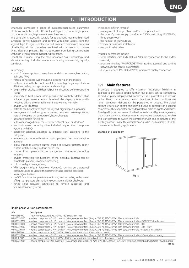
Example of a cold room
Fig. 1.a
Single-phase version part numbers
P/N DescriptionWE00S1EN00 1 relay: compressor (16 A), 230 Vac, 180° screw terminalsWE00C2HN00 4 relays: compressor (2 HP) , defrost (16 A), evaporator fans (8 A), AUX (8 A), 115/230 Vac, 180° screw terminalsWE00C2HM00 4 relays: compressor (2 HP) , defrost (16 A), evaporator fans (8 A), AUX (8 A), 115/230 Vac, 180° screw terminals + IROPZSER30 serial cardWE00C2HC00 4 relays: compressor (2 HP) , defrost (16 A), evaporator fans (8 A), AUX (8 A), 115/230 Vac, 180° screw terminals + RTCWE00C3HN00 4 relays: compressor (2 HP) , defrost (16 A), evaporator fans (8 A), AUX (8 A), 115/230 Vac, 180° screw terminals + 3 HP relayWE00C2HN0H 4 relays: compressor (2 HP) , defrost (16 A), evaporator fans (8 A), AUX (8 A), 115/230 Vac, 180° screw terminals, horizontal installationWE00S1ET00 1 relay: compressor (16 A), 230 Vac, 180° screw terminals + I/O switch and wiringWE00C2HT00 4 relays: compressor (2 HP) , defrost (16 A), evaporator fans (8 A), AUX (8 A), 115/230 Vac, 180° screw terminals + I/O switch and wiringWE00S1EN0A 1 relay: compressor (16 A), 230 Vac, 180° screw terminals, assembled with Ultra Power moduleWE00C2HN0A 4 relays: compressor (2 HP) , defrost (16 A), evaporator fans (8 A), AUX (8 A), 115/230 Vac, 180° screw terminals, assembled with Ultra Power module
Tab. 1.a
8
ENG
“SmartCella manual” +0300084EN - rel. 1.3 - 24.09.2020
Three-phase version part numbers
SMARTCELLA 3PHPart number DescriptionWP00E11A100 SMARTCELLA 3PH 400VAC, 4HP, S.SWITCH 1.6-2.5A, DEFROST 3PH 9KW, EVAP FAN 1PH/3PH 1KW, COND FAN 1PH 900W, LIGHT 1PH 800WWP00E21A100 SMARTCELLA 3PH 400VAC, 4HP, S.SWITCH 2.5-4A, DEFROST 3PH 9KW, EVAP FAN 1PH/3PH 1KW, COND FAN 1PH 900W, LIGHT 1PH 800WWP00E31A100 SMARTCELLA 3PH 400VAC, 4HP, S.SWITCH 4-6.3A, DEFROST 3PH 9KW, EVAP FAN 1PH/3PH 1KW, COND FAN 1PH 900W, LIGHT 1PH 800WWP00E41A100 SMARTCELLA 3PH 400VAC, 4HP, S.SWITCH 6.3-10A, DEFROST 3PH 9KW, EVAP FAN 1PH/3PH 1KW, COND FAN 1PH 900W, LIGHT 1PH 800WWP00E51A100 SMARTCELLA 3PH 400VAC, 4HP, S.SWITCH 8-12A, DEFROST 3PH 9KW, EVAP FAN 1PH/3PH 1KW, COND FAN 1PH 900W, LIGHT 1PH 800WWP00E42A200 SMARTCELLA 3PH 400VAC,7.5HP, S.SWITCH 6.3-10A, DEFROST 3PH 9KW, EVAP FAN 1PH/3PH 2KW,COND FAN 3PH 2KW, LIGHT 1PH 800WWP00E62A200 SMARTCELLA 3PH 400VAC, 7.5HP, S.SWITCH 10-16A, DEFROST 3PH 9KW, EVAP FAN 1PH/3PH 2KW, COND FAN 3PH 2KW, LIGHT 1PH 800WWP00E72A200 SMARTCELLA 3PH 400VAC, 7.5HP, S.SWITCH 16-20A, DEFROST 3PH 9KW, EVAP FAN 1PH/3PH 2KW, COND FAN 3PH 2KW, LIGHT 1PH 800WWP00E73B300 SMARTCELLA 3PH 400VAC, 10HP, S.SWITCH 16-20A, DEFROST 3PH 12KW, EVAP FAN 3PH 3.5KW, COND FAN 3PH 2+2KW, LIGHT 1PH 800W
Tab. 1.a
SMARTCELLA 3PH EVDPart number DescriptionWP00E11A1U0 SMARTCELLA 3PH EVD 400VAC, 4HP, S.SWITCH 1.6-2.5A, DEFROST 3PH 9KW, EVAP FAN 1PH/3PH 1KW, COND FAN 1PH 900W, LIGHT 1PH 800WWP00E21A1U0 SMARTCELLA 3PH EVD 400VAC, 4HP, S.SWITCH 2.5-4A, DEFROST 3PH 9KW, EVAP FAN 1PH/3PH 1KW, COND FAN 1PH 900W, LIGHT 1PH 800WWP00E31A1U0 SMARTCELLA 3PH EVD 400VAC, 4HP, S.SWITCH 4-6.3A, DEFROST 3PH 9KW, EVAP FAN 1PH/3PH 1KW, COND FAN 1PH 900W, LIGHT 1PH 800WWP00E41A1U0 SMARTCELLA 3PH EVD 400VAC, 4HP, S.SWITCH 6.3-10A, DEFROST 3PH 9KW, EVAP FAN 1PH/3PH 1KW, COND FAN 1PH 900W, LIGHT 1PH 800WWP00E51A1U0 SMARTCELLA 3PH EVD 400VAC, 4HP, S.SWITCH 8-12A, DEFROST 3PH 9KW, EVAP FAN 1PH/3PH 1KW, COND FAN 1PH 900W, LIGHT 1PH 800WWP00E42A2U0 SMARTCELLA 3PH EVD 400VAC, 7.5HP, S.SWITCH 6.3-10A, DEFROST 3PH 9KW, EVAP FAN 1PH/3PH 2KW,COND FAN 3PH 2KW, LIGHT 1PH 800WWP00E62A2U0 SMARTCELLA 3PH EVD 400VAC, 7.5HP, S.SWITCH 10-16A, DEFROST 3PH 9KW, EVAP FAN 1PH/3PH 2KW, COND FAN 3PH 2KW, LIGHT 1PH 800WWP00E72A2U0 SMARTCELLA 3PH EVD 400VAC, 7.5HP, S.SWITCH 16-20A, DEFROST 3PH 9KW, EVAP FAN 1PH/3PH 2KW, COND FAN 3PH 2KW, LIGHT 1PH 800WWP00E73B3U0 SMARTCELLA 3PH EVD 400VAC, 10HP, S.SWITCH 16-20A, DEFROST 3PH 12KW, EVAP FAN 3PH 3.5KW, COND FAN 3PH 2+2KW, LIGHT 1PH 800W
Tab. 1.b
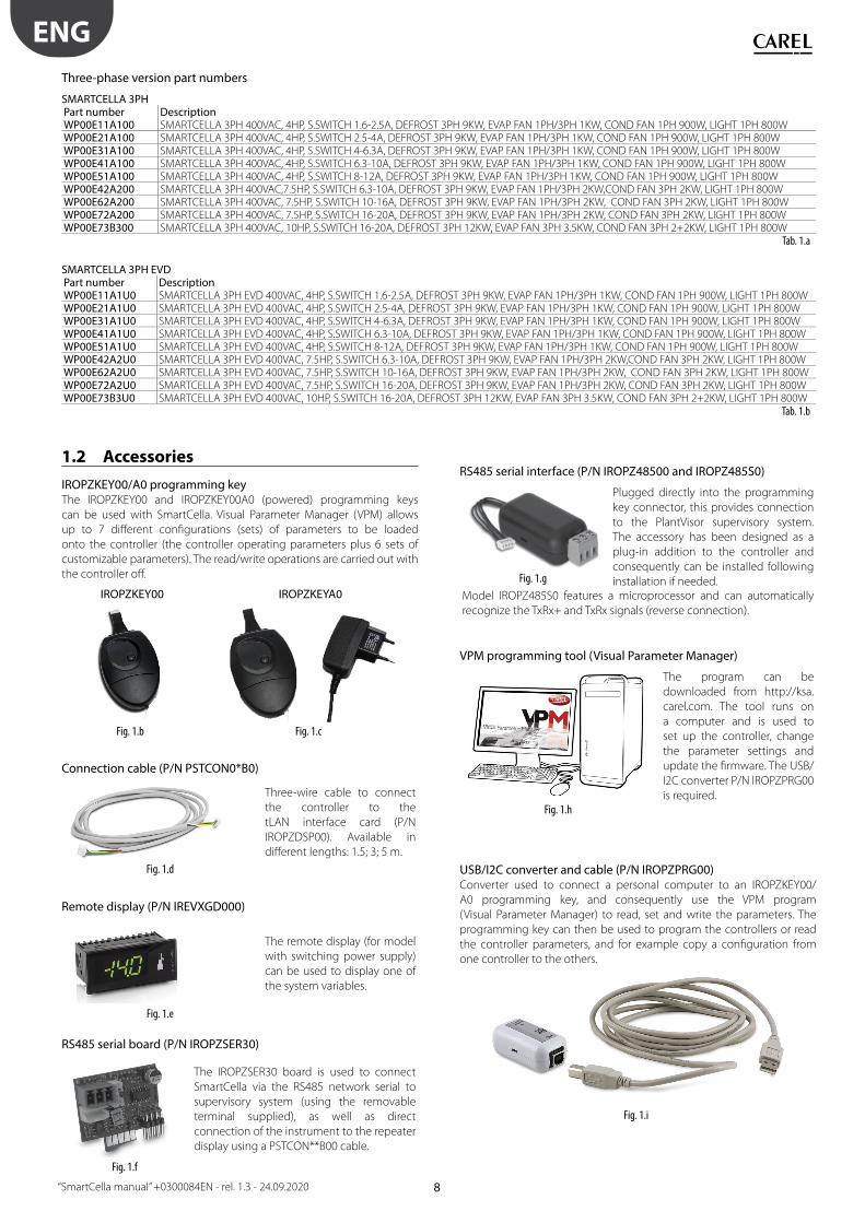
1.2 Accessories
IROPZKEY00/A0 programming keyThe IROPZKEY00 and IROPZKEY00A0 (powered) programming keys
can be used with SmartCella. Visual Parameter Manager (VPM) allows
up to 7 diff erent confi gurations (sets) of parameters to be loaded
onto the controller (the controller operating parameters plus 6 sets of
customizable parameters). The read/write operations are carried out with
the controller off .
IROPZKEY00 IROPZKEYA0
Fig. 1.b Fig. 1.c
Connection cable (P/N PSTCON0*B0)
Three-wire cable to connect
the controller to the
tLAN interface card (P/N
IROPZDSP00). Available in
diff erent lengths: 1.5; 3; 5 m.
Fig. 1.d
Remote display (P/N IREVXGD000)
The remote display (for model
with switching power supply)
can be used to display one of
the system variables.
Fig. 1.e
RS485 serial board (P/N IROPZSER30)
The IROPZSER30 board is used to connect
SmartCella via the RS485 network serial to
supervisory system (using the removable
terminal supplied), as well as direct
connection of the instrument to the repeater
display using a PSTCON**B00 cable.
Fig. 1.f
RS485 serial interface (P/N IROPZ48500 and IROPZ485S0)
Fig. 1.g
Plugged directly into the programming
key connector, this provides connection
to the PlantVisor supervisory system.
The accessory has been designed as a
plug-in addition to the controller and
consequently can be installed following
installation if needed. Model IROPZ485S0 features a microprocessor and can automatically
recognize the TxRx+ and TxRx signals (reverse connection).
VPM programming tool (Visual Parameter Manager)
The program can be
downloaded from http://ksa.
carel.com. The tool runs on
a computer and is used to
set up the controller, change
the parameter settings and
update the fi rmware. The USB/
I2C converter P/N IROPZPRG00
is required.Fig. 1.h
USB/I2C converter and cable (P/N IROPZPRG00)Converter used to connect a personal computer to an IROPZKEY00/
A0 programming key, and consequently use the VPM program
(Visual Parameter Manager) to read, set and write the parameters. The
programming key can then be used to program the controllers or read
the controller parameters, and for example copy a confi guration from
one controller to the others.
Fig. 1.i

9
ENG
“SmartCella manual” +0300084EN - rel. 1.3 - 24.09.2020
2. INSTALLATION
2.1 Dimensions (mm)
Single-phase version
26
0
47,5
47,5
30
128 101
29
0
87
,51
07
,5
Ø32
103
Fig. 2.a
Three-phase version
SmartCella 3PH
460
491
380 127
168
Fig. 2.b
SmartCella 3PH EVD
460
380
127
Fig. 2.c
Drilling template
SmartCella 3PH
Fig. 1.a
SmartCella 3PH EVD
Fig. 2.d

10
ENG
“SmartCella manual” +0300084EN - rel. 1.3 - 24.09.2020
2.2 Wall mounting
Single-phase version
2
1
1
2
1. Remove the faceplates (1 and 2) and unscrew the screws to open
the control
2. Release fl at connector to remove frontal panel
3. a. Mounting with DIN rail: Fix the DIN rail on the wall and insert the
controller. Mark the positions of the 2 bottom holes corresponding to
drilling template and extract the control. Drill the 2 holes (Ø 4,5 mm),
insert again the control and fi x the 2 bottom screws
3. b. Mounting without DIN rail: Mark the positions of the 4 holes
corresponding to drilling template, drill the holes (Ø 4,5 mm) and fi x
control to wall with 4 screws
4. Complete the wiring of the cables and the necessary components
5. Insert fl at connector and frontal panel box to electronic board. Close
the front panel fi xing the 4 supplied screws corresponding to the
holes
Three-phase version
1. With reference to the drilling template, drill the four fastening holes
in the wall:
• Unscrew the six fastening screws on the front panel
• Remove the front panel
• Fix the panel to the wall using screws of suitable length, based on
the thickness of the wall
2. Connect the power cables, the load power cables, the probes and
the remaining inputs/outputs to the terminal block on the panel, as
shown in the wiring diagram (see page 10/11)
3. Before starting installation, the motor protector should be calibrated
based on eff ective compressor power consumption, with reference
to the compressor’s rated data
4. Arm the circuit breakers and the motor protector
5. Close the front panel using the six screws
6. Power the panel on
7. Arm the main switch (yellow/red)
Warning
• separate the power cables (power supply, loads) from the signal cables
(probes, digital inputs) and the serial cable
• use cables that are suitably sized for the current they carry
• connect the terminal marked PE to the mains power supply earth
• after having powered the three-phase expansion, check correct
current draw of the various loads
2.3 Wiring diagram
Single-phase version
WE00SxExxx
6 71 2
21 20 19
L
N
8 9 10 11 12
PROBES DIDI DI
1 2 2 31
R1
serial interface
230 V~25mA~ max
POWERSUPPLY
-10T45°C IP 65
Fig. 2.e
WE00CxHxxx
5
R4
6 7
LN
1 2
24 23 22 21 20 19 15 14 13
L
N
8 9 10 11 12
PROBES DIDI DI
1 2 2 31
R1 R2 R3
serial interface
3 4
115…230 V~50mA~ max
POWERSUPPLY
-10T50°C IP 65
Fig. 2.f

11
ENG
“SmartCella manual” +0300084EN - rel. 1.3 - 24.09.2020
Three-phase version
SmartCella 3PH
WP00E11A100, WP00E21A100, WP00E31A100,
WP00E41A100, WP00E51A100
WP00E42A200, WP00E62A200, WP00E72A200
A1KRI QF2 QF1
KM2KM3KM1
U1
PE2
QM1 QS1
XA1
XP1
A1
XA1
XP1
QF2 QF1
KM1
KM4
KM3KM2
U1
PE2
KR1QM1 QS1
Fig. 2.g Fig. 2.h
WP00E73B300
A1
KM5
XA1
XP1
KM4
QF2 QF1
KM1 KM3KM2
U1
PE2
KR1QM1 QS1
Fig. 2.i
Code DescriptionA1 SmartCella electronic boardKR1 Alarm relayHL2 Evaporator lightHL3 Compressor lightHL4 Alarm lightHL5 Defrost lightKM1 Evaporator fan contactorKM2 Compressor contactorKM3 Defrost heater contactorKR1 Alarm relayQF1 Evaporator/condenser fan/defrost heater circuit breakerQF2 Auxiliary circuit breakerQM1 Compressor motor protectorQS1 Main disconnect switchXA1 Auxiliary terminal blockXP1 Power terminal blockKM4 3-pole condenser contactor, 4 kW/400 Vac3KM5 3-pole condenser contactor, 4 kW/400 Vac3KRI Compressor relayPE2 EarthPE1 EarthPE3 EarthU1 Earth terminalFU1 Safety fuses
12
ENG
“SmartCella manual” +0300084EN - rel. 1.3 - 24.09.2020
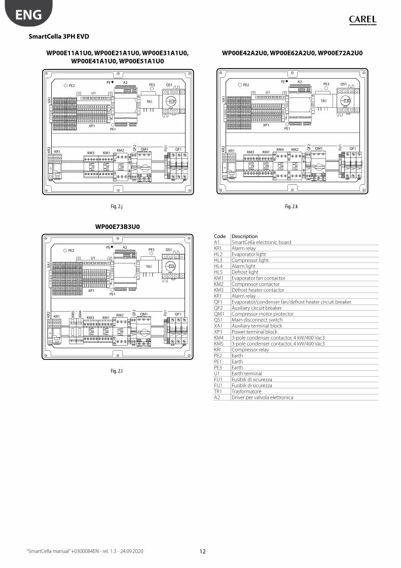
SmartCella 3PH EVD
WP00E11A1U0, WP00E21A1U0, WP00E31A1U0,
WP00E41A1U0, WP00E51A1U0
WP00E42A2U0, WP00E62A2U0, WP00E72A2U0XA
1
KM3KR1
PE2 PE3 QS1
TR1
U1
PE A2
XP1PE1
KR2
KM1KM2 QM1 QF1Q
F2
FU1
XA1
KM3KR1
PE2 PE3 QS1
TR1
U1
PE A2
XP1PE1
KR2
KM1KM4 KM2 QM1 QF1Q
F2
FU1
Fig. 2.j Fig. 2.k
WP00E73B3U0
XA1
KM3KR1
PE2 PE3 QS1
TR1
U1
PE A2
XP1PE1
KR2
KM1KM2 QM1 QF1Q
F2
FU1
KM5
KM4
Fig. 2.l
Code DescriptionA1 SmartCella electronic boardKR1 Alarm relayHL2 Evaporator lightHL3 Compressor lightHL4 Alarm lightHL5 Defrost lightKM1 Evaporator fan contactorKM2 Compressor contactorKM3 Defrost heater contactorKR1 Alarm relayQF1 Evaporator/condenser fan/defrost heater circuit breakerQF2 Auxiliary circuit breakerQM1 Compressor motor protectorQS1 Main disconnect switchXA1 Auxiliary terminal blockXP1 Power terminal blockKM4 3-pole condenser contactor, 4 kW/400 Vac3KM5 3-pole condenser contactor, 4 kW/400 Vac3KRI Compressor relayPE2 EarthPE1 EarthPE3 EarthU1 Earth terminalFU1 Fusibili di sicurezzaFU1 Fusibili di sicurezzaTR1 TrasformatoreA2 Driver per valvola elettronica
13
ENG
“SmartCella manual” +0300084EN - rel. 1.3 - 24.09.2020
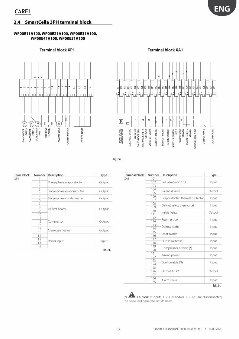
2.4 SmartCella 3PH terminal block
WP00E11A100, WP00E21A100, WP00E31A100,
WP00E41A100, WP00E51A100
1 2 3 4 5 6 7 8 9 10 11 12 13 14 15 L1 L2 L3 N
M3 ~ MM
1 ~M1 ~
101
102
103
104
105
106
107
108
109
110
111
112
114
113
115
116
117
118
119
121
120
122
123
124
125
126
127
134
135
P
Terminal block XP1
SOLE
NO
ID V
ALV
E
PRES
SURE
EVA
PORA
TOR
FAN
THER
MA
L SA
FETY
DEF
ROST
INTE
RNA
L LI
GH
TS
AM
BIEN
T PR
OBE
DEF
ROST
PRO
BE
MIC
RO S
WIT
CH
PRES
SUR
SWIT
CH
HP/
LP
COM
PRES
SOR
KRIW
AN
POW
ER S
UPP
LYKR
IWA
N
CON
FIG
URA
BLE
IDS
EVA
PORA
TOR
FAN
3~
EVA
PORA
TOR
FAN
1~
CON
DEN
SER
FAN
1~
DEF
ROST
HEA
TERS
COM
PRES
SOR
CA
RTER
HEA
TER
POW
ER IN
PUT
Terminal block XA1
PUM
P-D
OW
NM
AN
AG
EMEN
T
ALA
RM C
HA
IN
OU
TPU
T A
UX
2
Fig. 2.m
Term. block Number Description TypeXP1 1
Three-phase evaporator fan Output233
Single-phase evaporator fan Output54
Single-phase condenser fan Output67
Defrost heater Output89
1011
Compressor Output121314
Crankcase heater Output15L1
Power input InputL2L3N
Tab. 2.b
Terminal block Number Description TypeXA1 101
See paragraph 1.12 Input102103104
Solenoid valve Output105106
Evaporator fan thermal protector Input107108
Defrost safety thermostat Input109110
Inside lights Output111112
Room probe Input114113
Defrost probe Input114115
Door switch Input116117
HP/LP switch (*) Input118119
Compressor Kriwan (*) Input120121
Kriwan power Input122123
Confi gurable DIs Input124125
Output AUX2 Output126127134
Alarm chain Input135
Tab. 2.c
(*) Caution: if inputs 117-118 and/or 119-120 are disconnected,
the panel will generate an “IA” alarm

14
ENG
“SmartCella manual” +0300084EN - rel. 1.3 - 24.09.2020
WP00E42A200, WP00E62A200, WP00E72A2001 2 3 4 5 6 7 8 9 10 11 12 13 14 15 16 10
110
210
310
410
510
610
710
810
911
011
111
211
4
113
115
116
117
118
119
121
120
122
123
124
125
126
127
134
135
L1 L2 L3 N
M3 ~ MM
1 ~M3 ~
P
Terminal block XA1
EVA
PORA
TOR
FAN
3~
EVA
PORA
TOR
FAN
1~
CON
DEN
SER
FAN
3~
COM
PRES
SOR
CA
RTER
HEA
TER
POW
ER IN
PUT
DEF
ROST
HEA
TERS
SOLE
NO
ID V
ALV
E
PRES
SURE
EVA
PORA
TOR
FAN
THER
MA
L SA
FETY
DEF
ROST
INTE
RNA
L LI
GH
TS
AM
BIEN
T PR
OBE
DEF
ROST
PRO
BE
MIC
RO S
WIT
CH
PRES
SUR
SWIT
CH
HP/
LP
COM
PRES
SOR
KRIW
AN
POW
ER S
UPP
LYKR
IWA
N
CON
FIG
URA
BLE
IDS
Terminal block XP1
PUM
P-D
OW
NM
AN
AG
EMEN
T
ALA
RM C
HA
IN
OU
TPU
T A
UX
2
Fig. 2.n
Term. block Number Description TypeXP1 1
Three-phase evaporator fan Output233
Single-phase evaporator fan Output74
Three-phase condenser fan Output568
Defrost heater Output9
101112
Compressor Output131415
Crankcase heater Output16L1
Power input InputL2L3N
Tab. 2.d
Terminal block Number Description TypeXA1 101
See paragraph 1.12 Input102103104
Solenoid valve Output105106
Evaporator fan thermal protector Input107108
Defrost safety thermostat Input109110
Inside lights Output111112
Room probe Input114113
Defrost probe Input114115
Door switch Input116117
HP/LP switch (*) Input118119
Compressor Kriwan (*) Input120121
Kriwan power Input122123
Confi gurable DIs Input124125
Output AUX2 Output126127134
Alarm chain Input135
Tab. 2.e
(*) Caution: if inputs 117-118 and/or 119-120 are disconnected,
the panel will generate an “IA” alarm

15
ENG
“SmartCella manual” +0300084EN - rel. 1.3 - 24.09.2020
WP00E73B300
1 2 3 7 8 9 10 12 13 14 15 16 101
102
103
104
105
106
5A 4A 6A 5B 4B 6B 107
108
109
110
111
112
114
113
115
116
117
118
119
121
120
122
123
124
125
126
127
134
143
144
145
135
L1 L2 L3 N
M3 ~
M3 ~
M3 ~
M3 ~
P
DEF
ROST
HEA
TERS
CON
DEN
SER
FAN
3~
CON
DEN
SER
FAN
3~
EVA
PORA
TOR
FAN
3~
COM
PRES
SOR
3~
CA
RTER
HEA
TER
POW
ER IN
PUT
PRES
SURE
SW
ITC
H L
P
SAFE
TY T
HER
MO
STAT
DEF
ROST
INTE
RNA
L LI
GH
TS
AM
BIEN
T PR
OBE
DEF
ROST
PRO
BE
MIC
RO S
WIT
CH
PRES
SUR
SWIT
CH
HP/
LP
DIF
FERE
NTI
AL
PRES
SURE
SW
ITC
H
COM
PRES
SOR
KRIW
AN
POW
ER S
UPP
LYKR
IWA
N
CON
FIG
URA
BLE
DIs
Terminal block XP1 Terminal block XA1
SOLE
NO
ID V
ALV
E
PUM
P-D
OW
NM
AN
AG
EMEN
T
ALA
RM C
HA
IN
OU
TPU
T A
UX
2
Fig. 2.o
Term. block Number Description TypeXP1 5A
Three-phase evaporator fan Output4A6A5B
Three-phase condenser fan Output4B6B1
Three-phase evaporator fan Output237
Defrost heater Output89
1012
Three-phase compressor Output131415
Crankcase heater Output16L1
Power input InputL2L3N
Tab. 2.f
Terminal block Number Description TypeXA1 101
See paragraph 1.12 Input102103104
Solenoid valve Output105106
Evaporator fan thermal protector Input107108
Defrost safety thermostat Input109110
Inside lights Output111112
Room probe Input114113
Defrost probe Input114115
Door switch Input116117
HP/LP switch (*) Input118119
Compressor Kriwan (*) Input120121
Kriwan power Input122123
Confi gurable DIs Input124125
Output AUX2 Output126127134
Alarm chain Input135143
Diff erential pressure switch Input144145
Tab. 2.g
(*) Caution: if inputs 117-118 and/or 119-120 are disconnected,
the panel will generate an “IA” alarm
16
ENG
“SmartCella manual” +0300084EN - rel. 1.3 - 24.09.2020
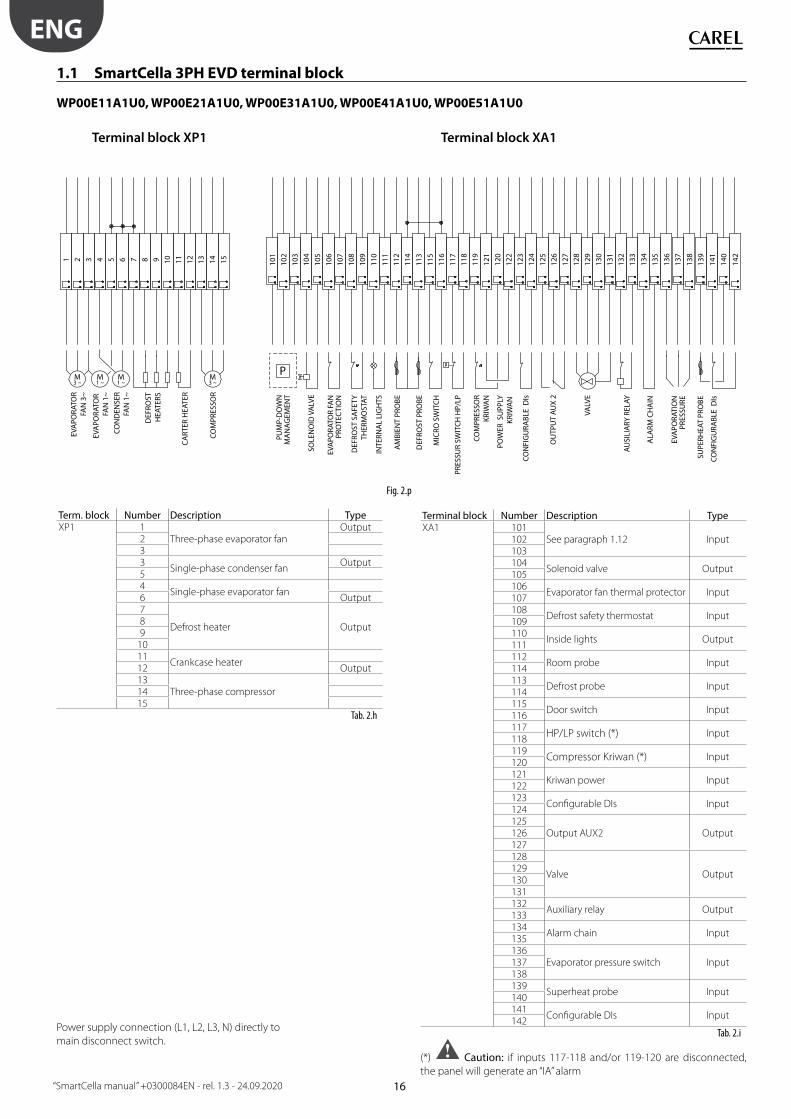
1.1 SmartCella 3PH EVD terminal block
WP00E11A1U0, WP00E21A1U0, WP00E31A1U0, WP00E41A1U0, WP00E51A1U0
1 2 3 4 5 6 7 8 9 10 11 12 13 14 15
M3 ~
M3 ~
M1 ~
M1 ~
101
102
103
104
105
106
107
108
109
110
111
112
114
113
115
116
117
118
119
121
120
122
123
124
125
126
127
128
129
130
131
132
133
134
135
136
137
138
139
141
140
142
P
VALV
E
AU
SILI
ARY
REL
AY
EVA
PORA
TOR
FAN
PRO
TEC
TIO
N
DEF
ROST
SA
FETY
THER
MO
STAT
INTE
RNA
L LI
GH
TS
AM
BIEN
T PR
OBE
DEF
ROST
PRO
BE
MIC
RO S
WIT
CH
PRES
SUR
SWIT
CH
HP/
LP
COM
PRES
SOR
KRIW
AN
POW
ER S
UPP
LYKR
IWA
N
CON
FIG
URA
BLE
DIs
EVA
PORA
TOR
FAN
3~
EVA
PORA
TOR
FAN
1~
CON
DEN
SER
FAN
1~
EVA
PORA
TIO
NPR
ESSU
RE
SUPE
RHEA
T PR
OBE
CON
FIG
URA
BLE
DIs
COM
PRES
SOR
CA
RTER
HEA
TER
Terminal block XP1 Terminal block XA1D
EFRO
STH
EATE
RS
SOLE
NO
ID V
ALV
E
PUM
P-D
OW
NM
AN
AG
EMEN
T
ALA
RM C
HA
IN
OU
TPU
T A
UX
2
Fig. 2.p
Term. block Number Description TypeXP1 1
Three-phase evaporator fanOutput
233
Single-phase condenser fanOutput
54
Single-phase evaporator fan6 Output7
Defrost heater Output89
1011
Crankcase heater12 Output13
Three-phase compressor1415
Tab. 2.h
Power supply connection (L1, L2, L3, N) directly to
main disconnect switch.
Terminal block Number Description TypeXA1 101
See paragraph 1.12 Input102103104
Solenoid valve Output105106
Evaporator fan thermal protector Input107108
Defrost safety thermostat Input109110
Inside lights Output111112
Room probe Input114113
Defrost probe Input114115
Door switch Input116117
HP/LP switch (*) Input118119
Compressor Kriwan (*) Input120121
Kriwan power Input122123
Confi gurable DIs Input124125
Output AUX2 Output126127128
Valve Output129130131132
Auxiliary relay Output133134
Alarm chain Input135136
Evaporator pressure switch Input137138139
Superheat probe Input140141
Confi gurable DIs Input142
Tab. 2.i
(*) Caution: if inputs 117-118 and/or 119-120 are disconnected,
the panel will generate an “IA” alarm

17
ENG
“SmartCella manual” +0300084EN - rel. 1.3 - 24.09.2020
WP00E42A2U0, WP00E62A2U0, WP00E72A2U0
1 2 3 4 5 6 7 8 9 10 11 12 13 14 15 16
M3 ~
M3 ~
M3 ~
M3 ~
101
102
103
104
105
106
107
108
109
110
111
112
114
113
115
116
117
118
119
121
120
122
123
124
125
126
127
128
129
130
131
132
133
134
135
136
137
138
139
141
140
142
P
EVA
PORA
TOR
FAN
PRO
TEC
TIO
N
SAFE
TY T
HER
MO
STAT
DEF
ROST
INTE
RNA
L LI
GH
TS
AM
BIEN
T PR
OBE
DEF
ROST
PRO
BE
MIC
RO S
WIT
CH
PRES
SUR
SWIT
CH
HP/
LP
COM
PRES
SOR
KRIW
AN
POW
ER S
UPP
LYKR
IWA
N
CON
FIG
URA
BLE
DIs
EVA
PORA
TOR
FAN
3~
EVAPORATORFAN 3~
CONDENS.FAN 3~
EVA
PORA
TOR
PRES
SURE
PRO
BE
SUPE
RHEA
T PR
OBE
CON
FIG
URA
BLE
DIs
COM
PRES
SOR
DEF
ROST
HEA
TERS
VALV
E
CA
RTER
HEA
TER
Terminal block XP1 Terminal block XA1
AU
XIL
IARY
REL
AY
SOLE
NO
ID V
ALV
E
PUM
P-D
OW
NM
AN
AG
EMEN
T
ALA
RM C
HA
IN
OU
TPU
T A
UX
2
Fig. 2.q
Term. block Number Description TypeXP1 1
Three-phase evaporator fan Output233
Three-phase condenser fan Output74
Single-phase evaporator fan Output568
Defrost heater Output9
101112
Three-phase compressor Output131415
Crankcase heater Output16
Tab. 2.j
Power supply connection (L1, L2, L3, N) directly to main disconnect
switch.
Terminal block Number Description TypeXA1 101
See paragraph 1.12 Input102103104
Solenoid valve Output105106
Evaporator fan thermal protector Input107108
Defrost safety thermostat Input109110
Inside lights Output111112
Room probe Input114113
Defrost probe Input114115
Door switch Input116117
HP/LP switch (*) Input118119
Compressor Kriwan (*) Input120121
Kriwan power Input122123
Confi gurable DIs Input124125
Output AUX2 Output126127128
Valve Output129130131132
Auxiliary relay Output133134
Alarm chain Input135136
Evaporator pressure switch Input137138139
Superheat probe Input140141
Confi gurable DIs Input142
Tab. 2.k
(*) Caution: if inputs 117-118 and/or 119-120 are disconnected,
the panel will generate an “IA” alarm
18
ENG
“SmartCella manual” +0300084EN - rel. 1.3 - 24.09.2020
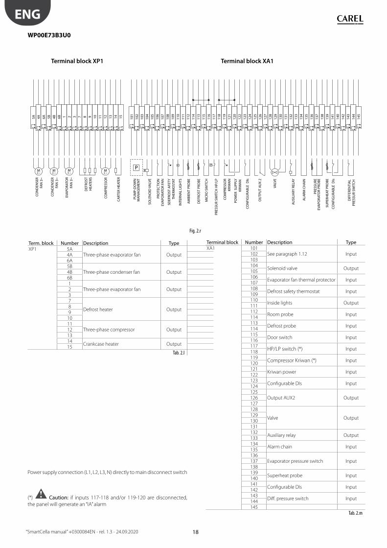
WP00E73B3U0
1 2 3 7 8 9 10 11 12 13 14 15
M3 ~
M3 ~
M3 ~
M3 ~
101
102
103
104
105
106
5A 4A 6A 5B 4B 6B 107
108
109
110
111
112
114
113
115
116
117
118
119
121
120
122
123
124
125
126
127
128
129
130
131
132
133
134
135
136
137
138
139
141
140
142
143
145
144
P
AU
SILI
ARY
REL
AY
PRO
TEC
TIO
NEV
APO
RATO
R FA
N
SDEF
ROST
AFE
TYTH
ERM
OST
AT
INTE
RNA
L LI
GH
TS
AM
BIEN
T PR
OBE
DEF
ROST
PRO
BE
MIC
RO S
WIT
CH
DIF
FERE
NTI
AL
PRES
SUR
SWIT
CH
PRES
SUR
SWIT
CH
HP/
LP
COM
PRES
SOR
KRIW
AN
POW
ER S
UPP
LYKR
IWA
N
EVA
PORA
TOR
FAN
3~
CON
DEN
SER
FAN
3~
CON
DEN
SER
FAN
3~
PRES
SURE
EVA
PORA
TOR
PRO
BE
SUPE
RHEA
T PR
OBE
CON
FIG
URA
BLE
DIs
COM
PRES
SOR
DEF
ROST
HEA
TERS
VALV
E
CON
FIG
URA
BLE
DIs
CA
RTER
HEA
TER
Terminal block XP1 Terminal block XA1
SOLE
NO
ID V
ALV
E
PUM
P-D
OW
NM
AN
AG
EMEN
T
ALA
RM C
HA
IN
OU
TPU
T A
UX
2
Fig. 2.r
Term. block Number Description TypeXP1 5A
Three-phase evaporator fan Output4A6A5B
Three-phase condenser fan Output4B6B1
Three-phase evaporator fan Output237
Defrost heater Output89
1011
Three-phase compressor Output121314
Crankcase heater Output15
Tab. 2.l
Power supply connection (L1, L2, L3, N) directly to main disconnect switch
(*) Caution: if inputs 117-118 and/or 119-120 are disconnected,
the panel will generate an “IA” alarm
Terminal block Number Description TypeXA1 101
See paragraph 1.12 Input102103104
Solenoid valve Output105106
Evaporator fan thermal protector Input107108
Defrost safety thermostat Input109110
Inside lights Output111112
Room probe Input114113
Defrost probe Input114115
Door switch Input116117
HP/LP switch (*) Input118119
Compressor Kriwan (*) Input120121
Kriwan power Input122123
Confi gurable DIs Input124125
Output AUX2 Output126127128
Valve Output129130131132
Auxiliary relay Output133134
Alarm chain Input135136
Evaporator pressure switch Input137138139
Superheat probe Input140141
Confi gurable DIs Input142143
Diff . pressure switch Input144145
Tab. 2.m

19
ENG
“SmartCella manual” +0300084EN - rel. 1.3 - 24.09.2020
2.5 InstallationTo install the controller, proceed as follows, with reference to the wiring
diagrams shown in the previous paragraphs:
1. connect the probes and power supply: the probes can be installed up
to a maximum distance of 10 m from the controller, using shielded
cables with a minimum cross-section of 1 mm². To improve immunity
to disturbance, use probes with shielded cables (connect only one end
of the shield to the earth on the electrical panel);
2. program the controller: as shown in the chapters “Commissioning” and
“User interface”;
3. connect the actuators: the actuators should only be connected after
having programmed the controller. Carefully check the maximum
capacities of the relays or three-phase contactors, as indicated in the
“technical specifi cations”;
4. serial network connection: all controllers are fi tted with a serial
connector for connection to the supervisor network via the serial
interface (IROPZ485*0 or serial board IROPZSER30). The secondary
of the transformers that supply the controllers must not be earthed.
If connection to a transformer with earthed secondary winding is
required, an insulating transformer must be installed in between.
Important: a separate transformer must be used for each controller,
- NEVER connect multiple controllers to the same transformer.
Warnings: avoid installing the controller in environments with the
following characteristics:
• relative humidity greater than 90% non-condensing;
• strong vibrations or knocks;
• exposure to continuous water sprays;
• exposure to aggressive and polluting atmospheric agents (e.g.: sulphur
and ammonia gases, saline mist, smoke) which may cause corrosion
and/or oxidation;
• strong magnetic and/or radio frequency interference (for example ,
near transmitting antennae);
• exposure to direct sunlight and the elements in general.
The following warnings must be observed when connecting the
controllers:
• incorrect connection of the power supply may seriously damage the
controller;
• use cable ends suitable for the corresponding terminals. Loosen each
screw and insert the cable ends, then tighten the screws and gently
pull the cables to check their tightness. When tightening the screws,
do not use automatic screwdrivers, rather adjust tool tightening
torque to less than 0.5Nm;
• separate as much as possible (by at least 3 cm) the probe signal and
digital input cables from inductive loads and power cables, to avoid
any electromagnetic disturbance. Never lay power cables and probe
cables in the same cable conduits (including those for the electrical
panels). Do not install the probe cables in the immediate vicinity of
power devices (contactors, circuit breakers or the like). Reduce the
length of the sensor cables as much as possible, and avoid spirals
around power devices;
• only use IP67 guaranteed probes as end defrost probes; place the
probes with the vertical bulb upwards, so as to facilitate drainage
of any condensate. Remember that thermistor temperature probes
(NTC) have no polarity, so the order the ends are connected in is not
important.
Cleaning the controllerWhen cleaning the controller do not use ethanol, hydrocarbons (petrol),
ammonia and by-products. Use neutral detergents and water.
2.6 Programming key IROPZKEY00/A0The programming key can load up to 7 diff erent parameter confi gurations
onto the controller (the controller operating parameters plus 6 sets
of customisable default parameters). The keys are plugged into the
connector (4 pin AMP) available on the controllers. All the operations can
be performed with the controller off .
Fig. 2.s
The functions are selected by setting the two dipswitches, accessible by
removing the battery cover.
UPLOAD DOWNLOAD EXTENDED DOWNLOAD
• load the parameters from a controller onto the key (UPLOAD);
• copy from the key to a controller (DOWNLOAD);
• extended copy from the key to a controller (EXTENDED DOWNLOAD).
Important: The parameters can only be copied between
controllers with the same part number. The UPLOAD operation can,
however, always be performed.
Copying and downloading the parametersThe following operations are used for the UPLOAD and/or DOWNLOAD
functions, simply by changing the settings of the dipswitches on the key:
1. open the rear cover on the key and position the 2 dipswitches
according to the desired operation;
2. close the rear cover on the key and plug the key into the connector
on the controller;
3. press the button and check the LED: red for a few seconds, then
green, indicates that the operation was completed correctly. Other
signals or the fl ashing of the LED indicates that problems have
occurred: see the table below;
4. at the end of the operation, release the button, after a few seconds
the LED goes off ;
5. remove the key from the controller.
LED signal Error Meaning and solution
Red LED
fl ashing
Batteries discharged at
start copy
The batteries are discharged,
the copy operation cannot be
performed. Replace the batteries.Green LED
fl ashing
Batteries discharged
during copy or at end
of copy
During the copy operation or
at the end of the operation the
battery level is low. Replace the
batteries and repeat the operation.Red/green
LEDs fl ashing
(orange signal)
Controller not
compatible
The parameter set-up cannot be
copied as the connected controller
model is not compatible. This error
only occurs for the DOWNLOAD
function; check the controller
P/N and run the copy only for
compatible models.Red and green
LEDs on
Error in data being
copied
Error in the data being copied.
The EEPROM on the controller
is corrupted, therefore the data
cannot be copied to/from the key.
20
ENG
“SmartCella manual” +0300084EN - rel. 1.3 - 24.09.2020
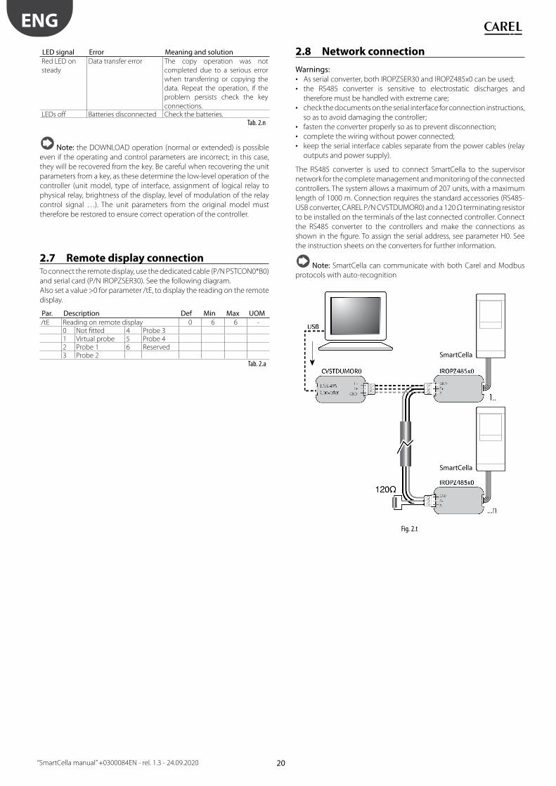
LED signal Error Meaning and solution
Red LED on
steady
Data transfer error The copy operation was not
completed due to a serious error
when transferring or copying the
data. Repeat the operation, if the
problem persists check the key
connections.LEDs off Batteries disconnected Check the batteries.
Tab. 2.n
Note: the DOWNLOAD operation (normal or extended) is possible
even if the operating and control parameters are incorrect; in this case,
they will be recovered from the key. Be careful when recovering the unit
parameters from a key, as these determine the low-level operation of the
controller (unit model, type of interface, assignment of logical relay to
physical relay, brightness of the display, level of modulation of the relay
control signal …). The unit parameters from the original model must
therefore be restored to ensure correct operation of the controller.
2.7 Remote display connectionTo connect the remote display, use the dedicated cable (P/N PSTCON0*B0)
and serial card (P/N IROPZSER30). See the following diagram.
Also set a value >0 for parameter /tE, to display the reading on the remote
display.
Par. Description Def Min Max UOM/tE Reading on remote display 0 6 6 -
0 Not fi tted 4 Probe 31 Virtual probe 5 Probe 42 Probe 1 6 Reserved3 Probe 2
Tab. 2.a
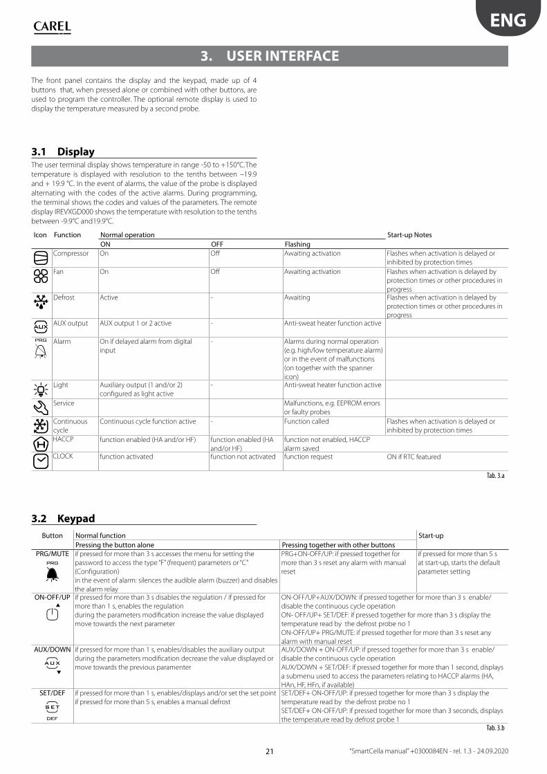
2.8 Network connection
Warnings:• As serial converter, both IROPZSER30 and IROPZ485x0 can be used;
• the RS485 converter is sensitive to electrostatic discharges and
therefore must be handled with extreme care;
• check the documents on the serial interface for connection instructions,
so as to avoid damaging the controller;
• fasten the converter properly so as to prevent disconnection;
• complete the wiring without power connected;
• keep the serial interface cables separate from the power cables (relay
outputs and power supply).
The RS485 converter is used to connect SmartCella to the supervisor
network for the complete management and monitoring of the connected
controllers. The system allows a maximum of 207 units, with a maximum
length of 1000 m. Connection requires the standard accessories (RS485-
USB converter, CAREL P/N CVSTDUMOR0) and a 120 Ω terminating resistor
to be installed on the terminals of the last connected controller. Connect
the RS485 converter to the controllers and make the connections as
shown in the fi gure. To assign the serial address, see parameter H0. See
the instruction sheets on the converters for further information.
Note: SmartCella can communicate with both Carel and Modbus
protocols with auto-recognition
SmartCella
SmartCella
Fig. 2.t
21
ENG
“SmartCella manual” +0300084EN - rel. 1.3 - 24.09.2020
3. USER INTERFACE
The front panel contains the display and the keypad, made up of 4
buttons that, when pressed alone or combined with other buttons, are
used to program the controller. The optional remote display is used to
display the temperature measured by a second probe.
3.1 DisplayThe user terminal display shows temperature in range -50 to +150°C.The
temperature is displayed with resolution to the tenths between –19.9
and + 19.9 °C. In the event of alarms, the value of the probe is displayed
alternating with the codes of the active alarms. During programming,
the terminal shows the codes and values of the parameters. The remote
display IREVXGD000 shows the temperature with resolution to the tenths
between -9.9°C and19.9°C.
Icon Function Normal operation Start-up Notes
ON OFF Flashing
Compressor On Off Awaiting activation Flashes when activation is delayed or
inhibited by protection times
Fan On Off Awaiting activation Flashes when activation is delayed by
protection times or other procedures in
progressDefrost Active - Awaiting Flashes when activation is delayed by
protection times or other procedures in
progressAUX output AUX output 1 or 2 active - Anti-sweat heater function active
Alarm On if delayed alarm from digital
input
- Alarms during normal operation
(e.g. high/low temperature alarm)
or in the event of malfunctions
(on together with the spanner
icon)Light Auxiliary output (1 and/or 2)
confi gured as light active
- Anti-sweat heater function active
Service Malfunctions, e.g. EEPROM errors
or faulty probes
Continuous
cycle
Continuous cycle function active - Function called Flashes when activation is delayed or
inhibited by protection times
HACCP function enabled (HA and/or HF) function enabled (HA
and/or HF)
function not enabled, HACCP
alarm savedCLOCK function activated function not activated function request ON if RTC featured
Tab. 3.a
3.2 Keypad
Button Normal function Start-up
Pressing the button alone Pressing together with other buttonsPRG/MUTE if pressed for more than 3 s accesses the menu for setting the
password to access the type “F” (frequent) parameters or “C”
(Confi guration)
in the event of alarm: silences the audible alarm (buzzer) and disables
the alarm relay
PRG+ON-OFF/UP: if pressed together for
more than 3 s reset any alarm with manual
reset
if pressed for more than 5 s
at start-up, starts the default
parameter setting
ON-OFF/UP if pressed for more than 3 s disables the regulation / if pressed for
more than 1 s, enables the regulation
during the parameters modifi cation increase the value displayed
move towards the next parameter
ON-OFF/UP+AUX/DOWN: if pressed together for more than 3 s enable/
disable the continuous cycle operation
ON- OFF/UP+ SET/DEF: if pressed together for more than 3 s display the
temperature read by the defrost probe no 1
ON-OFF/UP+ PRG/MUTE: if pressed together for more than 3 s reset any
alarm with manual resetAUX/DOWN if pressed for more than 1 s, enables/disables the auxiliary output
during the parameters modifi cation decrease the value displayed or
move towards the previous paramenter
AUX/DOWN + ON-OFF/UP: if pressed together for more than 3 s enable/
disable the continuous cycle operation
AUX/DOWN + SET/DEF: if pressed together for more than 1 second, displays
a submenu used to access the parameters relating to HACCP alarms (HA,
HAn, HF, HFn, if available)SET/DEF if pressed for more than 1 s, enables/displays and/or set the set point
if pressed for more than 5 s, enables a manual defrost
SET/DEF+ ON-OFF/UP: if pressed together for more than 3 s display the
temperature read by the defrost probe no 1
SET/DEF+ ON-OFF/UP: if pressed together for more than 3 seconds, displays
the temperature read by defrost probe 1Tab. 3.b

22
ENG
“SmartCella manual” +0300084EN - rel. 1.3 - 24.09.2020
3.3 Signal LEDs
Icon Colour Function Status NotesON OFF
Green POWER Auxiliary circuit powered Auxiliary circuit not powered LED on depending on the status (ON) of circuit
breaker QF2 and disconnect switch QS1Yellow COMPRESSOR Power available at compressor
power terminals
No power at compressor power
terminals
LED on depending on the status (ON) of motor
protector QM1 and whether power is availableYellow EVAPORATOR
FAN
Power available at evaporator fan
power terminals
No power at evaporator fan
power terminals
LED on depending on the status (ON) of circuit
breaker QF1 and whether power is availableYellow DEFROST Power available at defrost power
terminals
No power at defrost power
terminals
LED on depending on the status (ON) of circuit
breaker QF1 and whether power is availableRed ALARM Alarm activated Normal operation LED on depending on: activation of circuit
breaker QF1 and/or motor protector QM1
and/or alarm input (high pressure switch or
compressor Kriwan)Tab. 3.c
Note: the status of the LED (On/Off ) obviously depends on the
operating logic of the panel (e.g. if the temperature reaches the set point,
the compressor and the corresponding LED will be switched off by the
electronic controller, without generating alarms)
3.4 ProgrammingThe operating parameters can be modifi ed using the front keypad. Access
diff ers depending on the type: set point, frequently-used parameters (F)
and confi guration parameters (C). The type of parameter is specifi ed in the
table of parameters. Access to the confi guration parameters is protected
by a password for the confi guration parameters that prevents unwanted
modifi cations or access by unauthorised persons. The password can be
used to access and set all the control parameters.
3.4.1 Setting the set point
How to set the set point (desired temperature value)
Step Action Eff ect Meaning
1Press for 1
second
After 1 second the display will
show the current set point
This the currently
active control set
point2
Press or The value on the display will
increase or decrease
Set the desired
value3
Press The controller will show the
temp.read by the probes again
The set point is
modifi ed and
savedTab. 3.d
Another way of changing the set point is to set parameter “St” (see the
tables below)
3.4.2 Setting type “F” and “C” parameters
Step Action Eff ect Meaning
1Press for 3
seconds
After 3 seconds the
display will show the 1st
parameter, “0” (Password)
Access to type “F”
parameters is direct
without password2
Press or The value on the display
will increase or decrease.
Enter the password
“22” to access the
type “C” parameters
or whatever diff erent
value for the type “F”
parameters.3
Press The display will show “St”
(Setpoint)
This is the current value
of the Setpoint4
Press or If the password set is 22
the display will scroll the
list of type “C” parameters
(CONFIGURATION)
otherwise the list of type “F”
parameters (FREQUENT)
Set the desired value
5Press
The display will show the
parameter name
This is the current value
of the parameter6
Press or The value on the display
will increase or decrease
Set the desired value
Step Action Eff ect Meaning
7Press
The display will show the
parameter name again
IMPORTANT:
parameters not yet
saved8 Repeat steps
2, 3, 4 & 5 for
all parameters
required9
Press
for 5 seconds
The controller will display
the temperature read by
the probes again
IMPORTANT: only now
have all the parameters
been updatedTab. 3.e
For both types of access (type “F” and type “C”) there is a timeout (no
button on the keypad pressed for 1 min), the procedure is ended without
saving the parameter.
3.4.3 Parameter categories• To move from the parameters in one category to another, when
displaying the parameter code, press Prg to show the category and UP
and DOWN to move from one category to another;
• if no button is pressed for 10s, the display starts fl ashing, and after 1
minute automatically returns to the standard display;
• to increase the scrolling speed, press and hold the UP/DOWN button
for at least 5 seconds;
• all the changes made to the parameters, temporarily stored in the
RAM, can be cancelled, by not pressing any button for 60 seconds, thus
returning to the standard display.
Parameter categories
Category Text Icon Category Text IconProbes Pro
Alarms ALM
Control CtL
Fan FAn
Compressor CMP
Confi guration CnF
Defrost dEF
HACCP HcP
Clock rtc
Tab. 3.f
23
ENG
“SmartCella manual” +0300084EN - rel. 1.3 - 24.09.2020
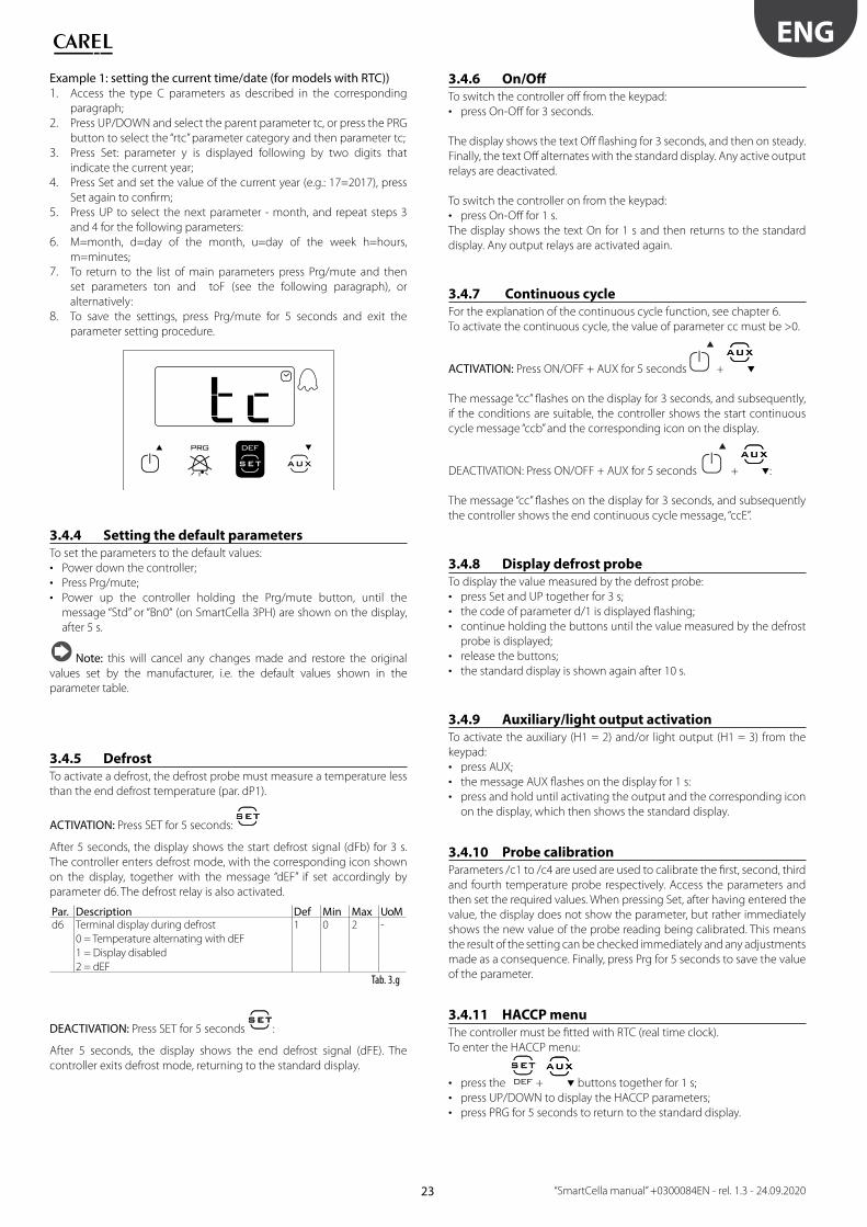
Example 1: setting the current time/date (for models with RTC))1. Access the type C parameters as described in the corresponding
paragraph;
2. Press UP/DOWN and select the parent parameter tc, or press the PRG
button to select the “rtc” parameter category and then parameter tc;
3. Press Set: parameter y is displayed following by two digits that
indicate the current year;
4. Press Set and set the value of the current year (e.g.: 17=2017), press
Set again to confi rm;
5. Press UP to select the next parameter - month, and repeat steps 3
and 4 for the following parameters:
6. M=month, d=day of the month, u=day of the week h=hours,
m=minutes;
7. To return to the list of main parameters press Prg/mute and then
set parameters ton and toF (see the following paragraph), or
alternatively:
8. To save the settings, press Prg/mute for 5 seconds and exit the
parameter setting procedure.
3.4.4 Setting the default parametersTo set the parameters to the default values:
• Power down the controller;
• Press Prg/mute;
• Power up the controller holding the Prg/mute button, until the
message “Std” or “Bn0“ (on SmartCella 3PH) are shown on the display,
after 5 s.
Note: this will cancel any changes made and restore the original
values set by the manufacturer, i.e. the default values shown in the
parameter table.
3.4.5 DefrostTo activate a defrost, the defrost probe must measure a temperature less
than the end defrost temperature (par. dP1).
ACTIVATION: Press SET for 5 seconds:
After 5 seconds, the display shows the start defrost signal (dFb) for 3 s.
The controller enters defrost mode, with the corresponding icon shown
on the display, together with the message “dEF” if set accordingly by
parameter d6. The defrost relay is also activated.
Par. Description Def Min Max UoMd6 Terminal display during defrost
0 = Temperature alternating with dEF
1 = Display disabled
2 = dEF
1 0 2 -
Tab. 3.g
DEACTIVATION: Press SET for 5 seconds :
After 5 seconds, the display shows the end defrost signal (dFE). The
controller exits defrost mode, returning to the standard display.
3.4.6 On/Off To switch the controller off from the keypad:
• press On-Off for 3 seconds.
The display shows the text Off fl ashing for 3 seconds, and then on steady.
Finally, the text Off alternates with the standard display. Any active output
relays are deactivated.
To switch the controller on from the keypad:
• press On-Off for 1 s.
The display shows the text On for 1 s and then returns to the standard
display. Any output relays are activated again.
3.4.7 Continuous cycleFor the explanation of the continuous cycle function, see chapter 6.
To activate the continuous cycle, the value of parameter cc must be >0.
ACTIVATION: Press ON/OFF + AUX for 5 seconds +
The message “cc” fl ashes on the display for 3 seconds, and subsequently,
if the conditions are suitable, the controller shows the start continuous
cycle message “ccb” and the corresponding icon on the display.
DEACTIVATION: Press ON/OFF + AUX for 5 seconds + :
The message “cc” fl ashes on the display for 3 seconds, and subsequently
the controller shows the end continuous cycle message, “ccE”.
3.4.8 Display defrost probeTo display the value measured by the defrost probe:
• press Set and UP together for 3 s;
• the code of parameter d/1 is displayed fl ashing;
• continue holding the buttons until the value measured by the defrost
probe is displayed;
• release the buttons;
• the standard display is shown again after 10 s.
3.4.9 Auxiliary/light output activationTo activate the auxiliary (H1 = 2) and/or light output (H1 = 3) from the
keypad:
• press AUX;
• the message AUX fl ashes on the display for 1 s:
• press and hold until activating the output and the corresponding icon
on the display, which then shows the standard display.
3.4.10 Probe calibrationParameters /c1 to /c4 are used are used to calibrate the fi rst, second, third
and fourth temperature probe respectively. Access the parameters and
then set the required values. When pressing Set, after having entered the
value, the display does not show the parameter, but rather immediately
shows the new value of the probe reading being calibrated. This means
the result of the setting can be checked immediately and any adjustments
made as a consequence. Finally, press Prg for 5 seconds to save the value
of the parameter.
3.4.11 HACCP menuThe controller must be fi tted with RTC (real time clock).
To enter the HACCP menu:
• press the + buttons together for 1 s;
• press UP/DOWN to display the HACCP parameters;
• press PRG for 5 seconds to return to the standard display.
24
ENG
“SmartCella manual” +0300084EN - rel. 1.3 - 24.09.2020
3.4.12 Minimum and maximum temperature
monitoringThe controller can record the minimum and maximum temperature
measured by the control probe over a period of up to 999 hours (more
than 41 days).
To enable monitoring:
• enter programming mode as explained in the corresponding
paragraph;
• set r5=1;
• select rt;
Press SET/DEF :
This displays how long minimum and maximum temperature monitoring
has been active, (if recording has just been enabled, rt=0);
• to restart temperature recording, press AUX for more than 5 s
The message “rES” indicates that the log has been deleted. The controller
resets the total hours and restarts monitoring;
• press Set to return to the list of parameters;
• to display the maximum temperature measured by the probe, read the
value associated with parameter rH;
• to display the minimum temperature measured by the probe, read the
value associated with parameter rL.
Note: after the maximum time of 999 hours, minimum and
maximum temperature monitoring continues, while the time interval
remains fi xed at 999.
Important: the values of parameters rt, rL and rH are saved to the
controller’s memory every hour. If the controller is not connected to an
uninterruptible power supply, a temporary blackout may mean the
values of rt, rL and rH measured in the last hour will be lost. When power
returns, the controller automatically restarts monitoring from the
previously saved values.
25
ENG
“SmartCella manual” +0300084EN - rel. 1.3 - 24.09.2020
4. COMMISSIONING
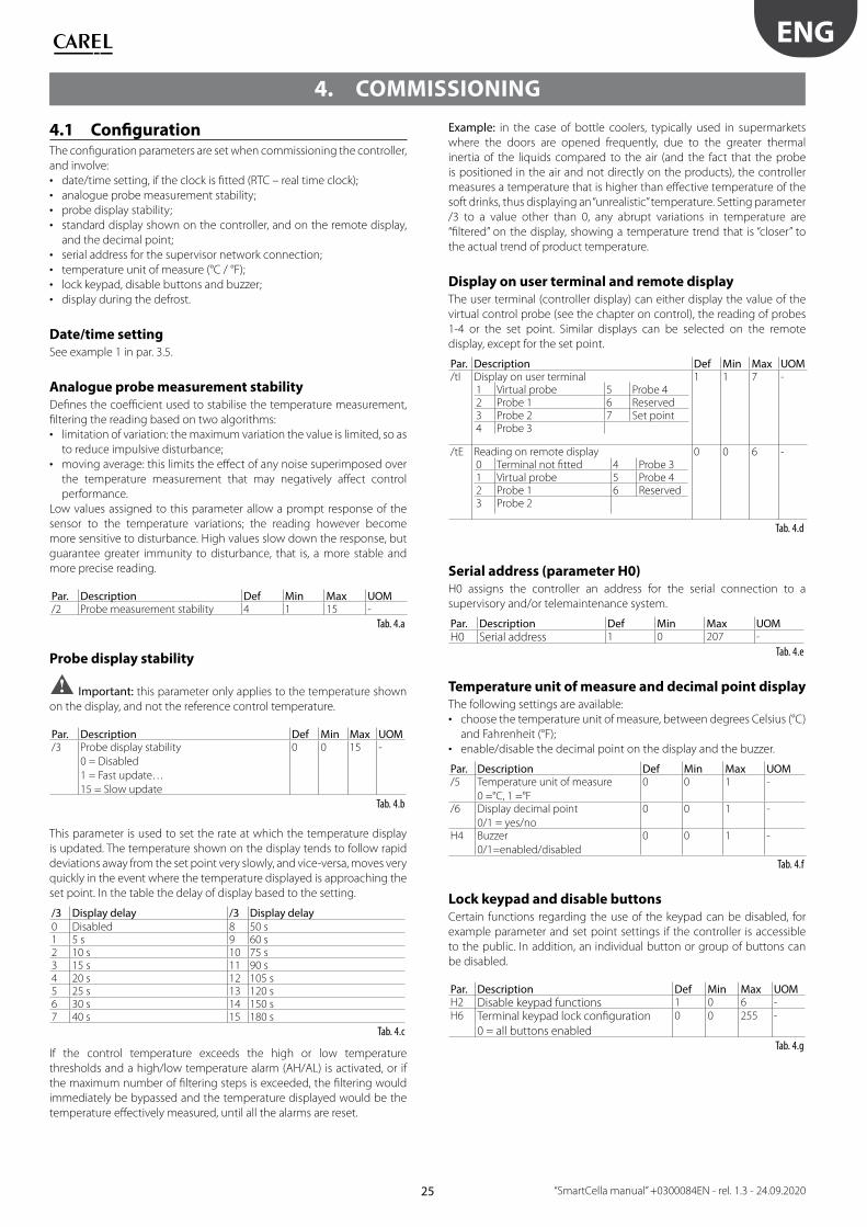
4.1 Confi gurationThe confi guration parameters are set when commissioning the controller,
and involve:
• date/time setting, if the clock is fi tted (RTC – real time clock);
• analogue probe measurement stability;
• probe display stability;
• standard display shown on the controller, and on the remote display,
and the decimal point;
• serial address for the supervisor network connection;
• temperature unit of measure (°C / °F);
• lock keypad, disable buttons and buzzer;
• display during the defrost.
Date/time settingSee example 1 in par. 3.5.
Analogue probe measurement stabilityDefi nes the coeffi cient used to stabilise the temperature measurement,
fi ltering the reading based on two algorithms:
• limitation of variation: the maximum variation the value is limited, so as
to reduce impulsive disturbance;
• moving average: this limits the eff ect of any noise superimposed over
the temperature measurement that may negatively aff ect control
performance.
Low values assigned to this parameter allow a prompt response of the
sensor to the temperature variations; the reading however become
more sensitive to disturbance. High values slow down the response, but
guarantee greater immunity to disturbance, that is, a more stable and
more precise reading.
Par. Description Def Min Max UOM/2 Probe measurement stability 4 1 15 -
Tab. 4.a
Probe display stability
Important: this parameter only applies to the temperature shown
on the display, and not the reference control temperature.
Par. Description Def Min Max UOM/3 Probe display stability
0 = Disabled
1 = Fast update…
15 = Slow update
0 0 15 -
Tab. 4.b
This parameter is used to set the rate at which the temperature display
is updated. The temperature shown on the display tends to follow rapid
deviations away from the set point very slowly, and vice-versa, moves very
quickly in the event where the temperature displayed is approaching the
set point. In the table the delay of display based to the setting.
/3 Display delay /3 Display delay0 Disabled 8 50 s1 5 s 9 60 s2 10 s 10 75 s3 15 s 11 90 s4 20 s 12 105 s5 25 s 13 120 s6 30 s 14 150 s7 40 s 15 180 s
Tab. 4.c
If the control temperature exceeds the high or low temperature
thresholds and a high/low temperature alarm (AH/AL) is activated, or if
the maximum number of fi ltering steps is exceeded, the fi ltering would
immediately be bypassed and the temperature displayed would be the
temperature eff ectively measured, until all the alarms are reset.
Example: in the case of bottle coolers, typically used in supermarkets
where the doors are opened frequently, due to the greater thermal
inertia of the liquids compared to the air (and the fact that the probe
is positioned in the air and not directly on the products), the controller
measures a temperature that is higher than eff ective temperature of the
soft drinks, thus displaying an “unrealistic” temperature. Setting parameter
/3 to a value other than 0, any abrupt variations in temperature are
“fi ltered” on the display, showing a temperature trend that is “closer” to
the actual trend of product temperature.
Display on user terminal and remote displayThe user terminal (controller display) can either display the value of the
virtual control probe (see the chapter on control), the reading of probes
1-4 or the set point. Similar displays can be selected on the remote
display, except for the set point.
Par. Description Def Min Max UOM/tI Display on user terminal
1 Virtual probe 5 Probe 42 Probe 1 6 Reserved3 Probe 2 7 Set point4 Probe 3
1 1 7 -
/tE Reading on remote display0 Terminal not fi tted 4 Probe 31 Virtual probe 5 Probe 42 Probe 1 6 Reserved3 Probe 2
0 0 6 -
Tab. 4.d
Serial address (parameter H0)H0 assigns the controller an address for the serial connection to a
supervisory and/or telemaintenance system.
Par. Description Def Min Max UOMH0 Serial address 1 0 207 -
Tab. 4.e
Temperature unit of measure and decimal point displayThe following settings are available:
• choose the temperature unit of measure, between degrees Celsius (°C)
and Fahrenheit (°F);
• enable/disable the decimal point on the display and the buzzer.
Par. Description Def Min Max UOM/5 Temperature unit of measure
0 =°C, 1 =°F
0 0 1 -
/6 Display decimal point
0/1 = yes/no
0 0 1 -
H4 Buzzer
0/1=enabled/disabled
0 0 1 -
Tab. 4.f
Lock keypad and disable buttonsCertain functions regarding the use of the keypad can be disabled, for
example parameter and set point settings if the controller is accessible
to the public. In addition, an individual button or group of buttons can
be disabled.
Par. Description Def Min Max UOMH2 Disable keypad functions 1 0 6 -H6 Terminal keypad lock confi guration
0 = all buttons enabled
0 0 255 -
Tab. 4.g

26
ENG
“SmartCella manual” +0300084EN - rel. 1.3 - 24.09.2020
Functions that can be disabled on the keypad
Important: if setting H2 ≠ 1, 3, the type F parameters cannot be set,
but rather only their values can be displayed. Type C parameters, being
password-protected, can always be set on the keypad following the
procedure described in chap. 3. If “set point” and “F parameter” setting is
disabled, the set point and the type F parameters cannot be set, but
rather only their values can be displayed.
Note: Y = can be activated / enabled; N = cannot be activated /
enabled
par. H2
FUNCTION 0 1 2 3 4 5 6LIGHT Y Y Y Y Y Y YAUX Y Y Y Y Y Y YON/OFF Y Y Y Y N N YHACCP Y Y Y Y Y Y YPRG/MUTE (mute) Y Y Y Y Y Y YUP+DOWN (continuous cycle) Y Y Y Y N N NSET/DEF (defrost) Y Y Y Y N N NSET (set point) setting N Y N Y Y N N“F” parameter setting N Y N Y N N N
Tab. 4.h
Disable buttonsUsing the individual bits, the functions relating to the buttons on the
keypad can be enabled or disabled, according to the relationships shown
in the table below: to calculate the value to be assigned to parameter H6,
simply sum the values assigned to the functions that should be disabled.
Note: the functions disabled using parameter H6 are added to
those disabled using parameter H2.
Disable buttons
Bit Value par. H6 Button Function
0 1 Display defrost temp.; enter HACCP; defrost
1 2Activation of
AUX output 1, continuous cycle
2 4 Up, On-Off
3 8 Mute alarms
Tab. 4.i
4.2 Loading the sets of parametersUp to 6 sets of custom parameters can be selected on the controller, after
having been loaded using the VPM programming tool (Visual Parameter
Manager, see appendix 1) and the programming key.
Procedure:
• power down the controller;
• power up while holding Prg/mute;
• the display will show the fi rst set: bn0;
• press UP/DOWN to select set bn1 to bn6. For example, select bn2;
• press Set to confi rm the selected set: the controller will load the set
of parameters called bn2 and then will return to the standard display.
Par. Description Def Min Max UOMHdn Number of default parameter sets available 0 0 6 -
Tab. 4.j
Note: bn0 is the default set of parameters on the controller, i.e. the
default confi guration. When one of sets bn1 to bn6 is loaded, bn0 is
overwritten with the new set and is consequently erased.
4.3 Preparing for operationOnce having completed the installation, confi guration and programming
procedures, before starting the controller, check that:
• the wiring has been completed correctly;
• the programming logic is suitable for controlling the unit and the
system being managed;
• if the controller is fi tted with RTC (clock), set the current time and date,
and the on and off times for the light/auxiliary output;
• set the standard display;
• set the “probe type” parameter based on the probe available and the
type of control (NTC, NTC-HT, PTC); note that the controllers that use
PTC probes may have diff erent part numbers from those that only use
NTC probes;
• set the type of defrost: heater or hot gas;
• set the temperature unit of measure (°C or °F);
• the protection functions (delay at start-up, rotation, minimum on and
off times for the outputs) are active.
Note: all the alarms with manual reset can be reset by pressing the
Prg and UP buttons together for more than 5 seconds. See the chapter on
“Alarms”.

27
ENG
“SmartCella manual” +0300084EN - rel. 1.3 - 24.09.2020
5. FUNCTIONS
5.1 Probes (analogue inputs)The SmartCella platform controllers feature a maximum of 5 analogue
inputs, which are used for NTC, high temperature NTC (NTC Enhanced
Range) or PTC temperature sensors (see the note below). Probes S3, S4
and S5 can also be confi gured as digital inputs. Probe S1 is the control
probe and its function cannot be changed; the functions of probes S2, S3,
S4, S5 can be selected using parameters /A2, /A3, /A4, /A5. The probes can
be calibrated to adjust their readings. In particular, parameters /c1 to /c5
are used to increase or decrease the values read by the probes connected
to inputs S1, S2, S3, S4, S5 across the entire the range of measurement. For
the calibration procedure, see paragraph 3.5.
Par. Description Def Min Max UOM/P Type of probe
0 = NTC Standard Range -50T90°C
1 = NTC Enhanced Range -40T150°C
2 = PTC Standard Range -50T150°C
0 0 2 -
/c1 Probe 1 calibration 0 -20 20 °C/°F/c2 Probe 2 calibration 0 -20 20 °C/°F/c3 Probe 3 calibration 0 -20 20 °C/°F/c4 Probe 4 calibration 0 -20 20 °C/°F/c5 Probe 5 calibration 0.0 -20 20 °C/°F
Tab. 5.a
AT1
T2
min max
Fig. 5.aKeyT1 Temperature read by the probeT2 Value calibrated by T1A Calibration valuemin, max Range of measurement
Assigning the functions of probes S2, S3, S4, S5The controller, inside the cold room, can use the following probes:
• defrost, located on the evaporator, preferably where ice remains the
longest;
• condenser, used to protect the compressor against high pressure
when the condenser is off or the condenser fan is malfunctioning;
• frost protection, to activate the corresponding alarm.
Note:
• to confi gure probes 3, 4 and 5 as digital input 1, 2 and 3 respectively,
set parameters /A3 e /A4 and /A5 =0;
• if multiple probes have been confi gured with the same operating
mode, the controller will use the fi rst probe in increasing order with
that confi guration.
Par. Description Def Min Max UOM/A2 Probe 2 confi guration (S2) (M models) 0 0 4 -/A2 Probe 2 confi guration (S2)
0 Absent1 Product (display only)2 Defrost3 Condenser4 Frost
2 0 4 -
/A3 Probe 3 confi guration (S3)
0 Digital input 1 (DI1)1 Product (display only)2 Defrost3 Condenser4 Frost
0 0 3 -
Par. Description Def Min Max UOM/A4 Probe 4 confi guration (S4/ DI2)
0 Digital input 2 (DI2)1 Product (display only)2 Defrost3 Condenser4 Frost
0 0 4 -
/A5 Probe 5 calibration (S5/ DI3)
0 Digital input 3 (DI3)1 Product (display only)2 Defrost3 Condenser4 Frost
0 0 4 -
Tab. 5.b
5.2 Digital inputsDigital inputs DI1, DI2 and DI3 respectively can be enabled in the place
of probes S3, S4 and S5. Digital inputs 1, 2, 3 must fi rst be enabled (par. /
A3 and /A4 = 0) and then assigned to a specifi c function (par. A4, A5 and
A9). Finally, an external contact can be connected to the multifunction
input to activate various types of functions, such as alarms, curtain/door
switches, start defrost, etc. See the table below.
Important: to ensure unit safety in the event of serious alarms, the
unit must be fi tted with all the electromechanical safety devices needed
to guarantee correct operation..
Note: (applies to all settings of par. A4, A5 and A9): if 2 digital inputs
are confi gured in the same way, for example to enable defrost, the disable
event is generated when at least one of the inputs is open, while the
enable event is generated when at both inputs are closed.
Digital input functions
PARAMETERS A4, A5 and A9Setting Contact
OPEN CLOSED
0 = not active - -1 = immediate external alarm active not active2 = delayed external alarm active not active3 = select probe see /tI fi rst probe
enabled (/A2,
/A3, /A4, /A5)3 = enable defrost (all other models) not enabled enabled4 = start defrost not active active5 = door switch with compressor and
evaporator fans off
door open door closed
6 = remote ON/OFF OFF ON7 = curtain switch curtain open curtain closed8 = low pressure switch low pressure
status
normal status
9 = door switch with fans off door open door closed10 = direct/reverse operation direct mode reverse mode11 = light sensor light off light on12 = activate aux output deactivated activated13 = door switch with compressor and fans
off and light not managed
door open door closed
14 = door switch with fans off and light not
managed
door open door closed
Tab. 5.c
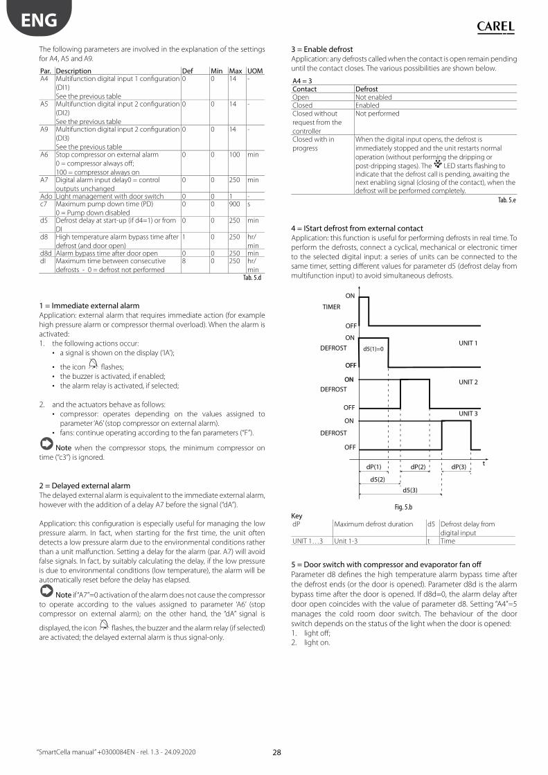
28
ENG
“SmartCella manual” +0300084EN - rel. 1.3 - 24.09.2020
The following parameters are involved in the explanation of the settings
for A4, A5 and A9.
Par. Description Def Min Max UOMA4 Multifunction digital input 1 confi guration
(DI1)
See the previous table
0 0 14 -
A5 Multifunction digital input 2 confi guration
(DI2)
See the previous table
0 0 14 -
A9 Multifunction digital input 2 confi guration
(DI3)
See the previous table
0 0 14 -
A6 Stop compressor on external alarm
0 = compressor always off ;
100 = compressor always on
0 0 100 min
A7 Digital alarm input delay0 = control
outputs unchanged
0 0 250 min
Ado Light management with door switch 0 0 1 -c7 Maximum pump down time (PD)
0 = Pump down disabled
0 0 900 s
d5 Defrost delay at start-up (if d4=1) or from
DI
0 0 250 min
d8 High temperature alarm bypass time after
defrost (and door open)
1 0 250 hr/
mind8d Alarm bypass time after door open 0 0 250 mindI Maximum time between consecutive
defrosts - 0 = defrost not performed
8 0 250 hr/
minTab. 5.d
1 = Immediate external alarmApplication: external alarm that requires immediate action (for example
high pressure alarm or compressor thermal overload). When the alarm is
activated:
1. the following actions occur:
• a signal is shown on the display (‘IA’);
• the icon fl ashes;
• the buzzer is activated, if enabled;
• the alarm relay is activated, if selected;
2. and the actuators behave as follows:
• compressor: operates depending on the values assigned to
parameter ‘A6’ (stop compressor on external alarm).
• fans: continue operating according to the fan parameters (“F”).
Note when the compressor stops, the minimum compressor on
time (“c3”) is ignored.
2 = Delayed external alarmThe delayed external alarm is equivalent to the immediate external alarm,
however with the addition of a delay A7 before the signal (“dA”).
Application: this confi guration is especially useful for managing the low
pressure alarm. In fact, when starting for the fi rst time, the unit often
detects a low pressure alarm due to the environmental conditions rather
than a unit malfunction. Setting a delay for the alarm (par. A7) will avoid
false signals. In fact, by suitably calculating the delay, if the low pressure
is due to environmental conditions (low temperature), the alarm will be
automatically reset before the delay has elapsed.
Note if “A7”=0 activation of the alarm does not cause the compressor
to operate according to the values assigned to parameter ‘A6’ (stop
compressor on external alarm); on the other hand, the “dA” signal is
displayed, the icon fl ashes, the buzzer and the alarm relay (if selected)
are activated; the delayed external alarm is thus signal-only.
3 = Enable defrostApplication: any defrosts called when the contact is open remain pending
until the contact closes. The various possibilities are shown below.
A4 = 3Contact DefrostOpen Not enabledClosed EnabledClosed without
request from the
controller
Not performed
Closed with in
progress
When the digital input opens, the defrost is
immediately stopped and the unit restarts normal
operation (without performing the dripping or
post-dripping stages). The LED starts fl ashing to indicate that the defrost call is pending, awaiting the next enabling signal (closing of the contact), when the defrost will be performed completely.
Tab. 5.e
4 = IStart defrost from external contactApplication: this function is useful for performing defrosts in real time. To
perform the defrosts, connect a cyclical, mechanical or electronic timer
to the selected digital input: a series of units can be connected to the
same timer, setting diff erent values for parameter d5 (defrost delay from
multifunction input) to avoid simultaneous defrosts.
ON
OFF
ON
OFFOFF
t
TIMER
OFF
dP(2)dP(1)
d5(2)
DEFROSTUNIT 1
UNIT 2
UNIT 3
DEFROST
ONON
OFF
ON
DEFROST
dP(3)
d5(1)=0
d5(3)
Fig. 5.bKeydP Maximum defrost duration d5 Defrost delay from
digital inputUNIT 1…3 Unit 1-3 t Time
5 = Door switch with compressor and evaporator fan off
Parameter d8 defi nes the high temperature alarm bypass time after
the defrost ends (or the door is opened). Parameter d8d is the alarm
bypass time after the door is opened. If d8d=0, the alarm delay after
door open coincides with the value of parameter d8. Setting “A4”=5
manages the cold room door switch. The behaviour of the door
switch depends on the status of the light when the door is opened:1. light off ;
2. light on.

29
ENG
“SmartCella manual” +0300084EN - rel. 1.3 - 24.09.2020
Case 1: light off when opening the door
If the door is opened with the light OFF:
• the compressor and the evaporator fans are switched off ;
• the light is switched on (only on models fi tted with at least 1 auxiliary
relay programmed as a light output);
• the reading displayed and the icon fl ash;
• the temperature alarms are disabled.
If the door remains open for a time longer than “d8” (d8d), the controller
resumes normal operation:
• the compressor and the evaporator fan are switched on, if needed;
• the light is switched off ;
• the reading on the display fl ashes;
• the buzzer and the alarm relay are activated;
• the temperature alarms are enabled with the delay “Ad”.
To stop the reading from fl ashing, close the door. When the door closes,
the controller resumes normal operation, switching off the light and
enabling the temperature alarm after the delay time “d8”. The compressor
is re-started, after any set protection times (see the “C” parameters).
Case 2: light on when opening the door
The icon is on. If the door is open with the light on, it is assumed the
user enters the cold room, turning on the light before entering, closing
the door behind him, and then exits the room, closing the door a second
time.
When the door is opened the fi rst time:
• the compressor and the evaporator fans are switched off ;
• the light stays on (only on models fi tted with at least 1 auxiliary relay
programmed as a light output);
• the reading is displayed and the icon fl ashes;
• the temperature alarms are disabled.
When the door is closed the fi rst time, the controller maintains the
previous situation:
• the compressor and the evaporator fans stay off ;
• the light stays on;
• the reading is displayed and the icon fl ashes;
• the temperature alarms are disabled.
Door opened the second time: no change.
When the door is closed the second time, the controller resumes
normal operation, switching off the light and enabling the temperature
alarm after the delay time “d8”. When the compressor re-starts, any set
protection times must elapse fi rst (see the “C” parameters).
If, after opening, the door remains open for a time longer than “d8” or
“d8d”, the controller resumes normal operation:
• compressor and evaporator fan switched on if needed;
• light off ;
• the reading on the display fl ashes;
• the buzzer and the alarm relay are activated;
• the temperature alarms are enabled with the delay “Ad”;
• when the door closes, the high temperature alarm bypass time after
door open d8 is not set.
To stop the reading from fl ashing, close the door.
If, after being closed for the fi rst time, the door remains closed for longer
than time “d8” or “d8d”, the controller resumes normal operation:
• compressor and evaporator fan switched on if needed;
• light off ;
• the temperature alarms are enabled with the delay “d8”;
• the high temperature alarm bypass time after door open d8 is set.
If, after the door is closed for the fi rst time, the light is switched off
manually, the controller resumes normal operation:
• compressor and evaporator fan switched on if needed;
• light off ;
• the temperature alarms are enabled with the delay “d8”;
• the high temperature alarm bypass time after door open d8 is set.
Note:
• if the light was previously switched on manually, when the door is
closed for the second time, it is automatically switched off ;
• even if the evaporator fan is managed by the “fan controller” (see the F
parameters), the fans are forced to stop when the door is open.
This algorithm resolves any problems relating to faults or malfunctions of
the door switch.
Doorswitch
Fig. 5.c
Note: if more than one digital input is confi gured as a door switch,
the door is considered open when at least one of the inputs is open.
6 = Remote On/Off The digital input may be programmed also as remote ON/OFF. When the
control is in OFF:
• the temperature is displayed alternating with the message “OFF”;
• the internal timer for parameter “dI” is updated. If “dI” expires when the
unit is OFF, a defrost is performed when the unit is switched on again;
• the auxiliary relay set as auxiliary and light output is active, the other
auxiliary outputs are off ;
• the buzzer and the alarm relay are deactivated;
• the controller does not perform the control functions, defrosts,
continuous cycle, signal temperature alarms and all other functions;
• the compressor protection times are observed;
When the controller is switched back on, all the functions are re-activated,
with the exception of:
• defrost on start-up;
• compressor and fan delay at power on.
Note: the ON/OFF from external digital input has priority over the
keypad and the supervisor;
7 = Curtain switch/set point variationIf the input is selected as a curtain switch, the controller modifi es the
set point when the contact closes, adding the value of parameter “r4”;
the new value is then used for all the functions relating to the set point
(e.g. relative high and low temperature alarms, control with dead band,
control with two compressor steps etc.). For example when “r4”=3.0
(default value), the set point is increased by 3 degrees from the value
used when the curtain is open.
Par. Description Def Min Max UOMr4 Automatic night-time set point variation 3 -20 20 °C/°F
Tab. 5.f

30
ENG
“SmartCella manual” +0300084EN - rel. 1.3 - 24.09.2020
St
Svrd
OFF
ONDI OPENCMP/FAN
DIRECT St
Svr4
OFF
ONDI CLOSED
rd
CMP/FAN
Fig. 5.dKey
St Set point rd Diff erentialCMP Compressor FAN FanSv Virtual probe r4 Automatic night-time set point variation
Note: if one of the auxiliary outputs is used to manage the light,
lowering the curtain automatically switches the light off , while raising it
switches the light on.
8 = Low pressure switch input for pump down
See par. 6.4. Setting “A4”=8 manages the low pressure switch. The low
pressure alarm “LP” is signalled when the low pressure switch is activated:
• during normal control (c7=0) with the compressor on, or alternatively
• with pump-down function confi gured (c7 >0), if the pump down valve
is open and the compressor is on.
The low pressure alarm signal is delayed by the time set for parameter
“A7”. The low pressure alarm “LP” stops the compressor.
ON
OFF
ON
OFF
t
CMP
LOW
Pressure switch
Pump downvalve
HIGH
OFF
ONLP Alarm
A7
Fig. 5.e
KeyCMP Compressor Pump down valve Pump down valvePressure Switch Pressure switch LP alarm Low pressure alarmt Time A7 Alarm signal delay
Note: this parameter, together with c7, c8, c9 and H1 allows
management of the “pump-down” algorithm (see par 6.3).
9 = Door switch with fan off only
Same as for option “A4”=5, with the diff erence being that when opening
the door only the evaporator fan is switched off .
10 = Direct/reverse operation
Important: when A4 = 10, the status of digital input has priority
over the setting of parameter r3 (direct/reverse operating mode).
When the contact is open, the controller operates in “direct” mode
(cooling), when the contact is closed, in “reverse” mode (heating). A switch
can therefore be connected to select heating or cooling operation.
St
Svrd
OFF
ONDI OPENCMP/FAN
r3 = 0, 1, 2
DIRECT
Svrd
OFF
ONDI CLOSEDCMP/FAN
r3 = 0, 1, 2
REVERSESt
Fig. 5.f KeySt Set point Sv Virtual proberd Diff erential CMP CompressorFAN Fan
11 = Light sensorThe digital input is used to read a light sensor (P/N PSOPZLHT00, actually an
analogue input, from which a digital signal is taken using the parameter or
threshold of the light sensor).
The light sensor can be located:
• in the door jamb (ref. A);
• inside the cold room or cabinet (ref. B).
Par. Description Def Min Max UOMAF Light sensor OFF time
0 Sensor in the door jamb
> 0 Sensor inside the cold room or cabinet
0 0 250 s
Tab. 5.g
BA
Fig. 5.g
A (AF=0) B (AF = 1)Light sensor
signal
The sensor signals
the opening and
closing of the door
The sensor signals the opening of
the door and detects light inside the
cabinet/cold room. The sensor also
signals closing of the doorInside light: on With the door open If the sensor detects lightInside light: off With the door
closed, minimum off
time of 5 s, to avoid
rapid, successive
impulses of the light
relay
Closing of the door is measured by
time, as the inside light will illuminate
the sensor. After the time AF (>0)
the inside light is switched off for 5
seconds. If the light sensor signals
darkness, the door must be closed and
the light will therefore remain off ;
if it signals light: the door is open and
the light will be switched on again.Tab. 5.h
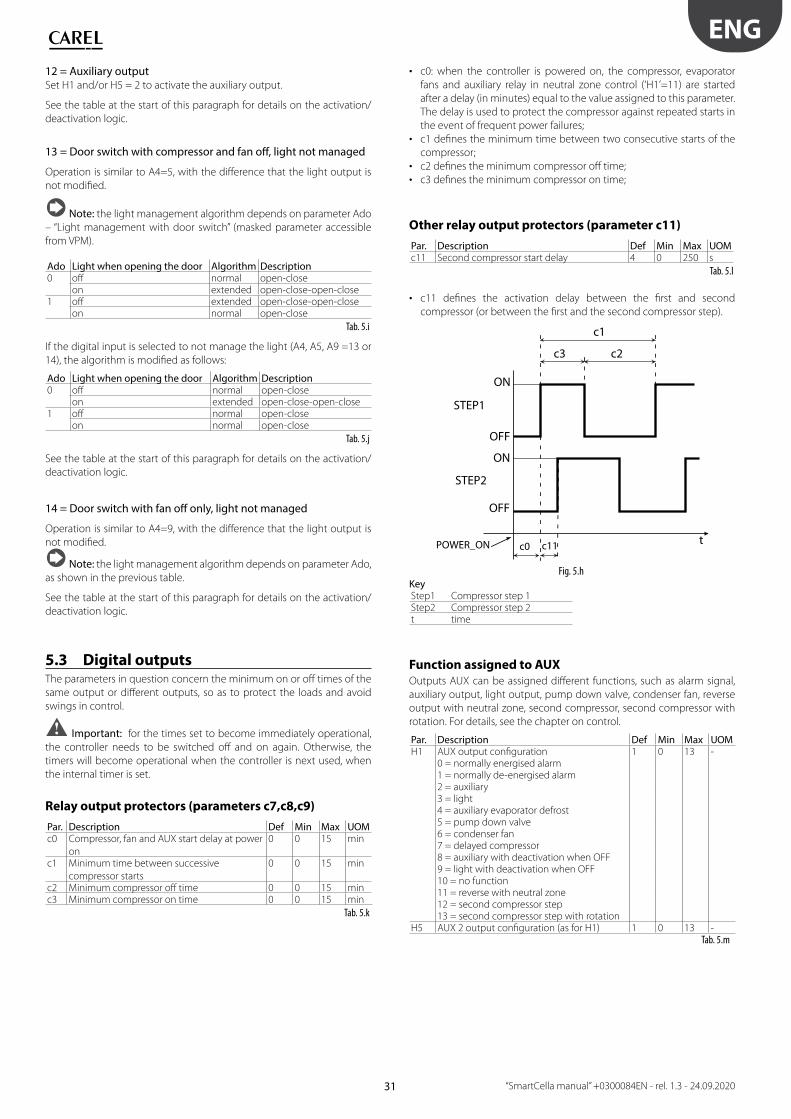
31
ENG
“SmartCella manual” +0300084EN - rel. 1.3 - 24.09.2020
12 = Auxiliary outputSet H1 and/or H5 = 2 to activate the auxiliary output.
See the table at the start of this paragraph for details on the activation/
deactivation logic.
13 = Door switch with compressor and fan off , light not managed
Operation is similar to A4=5, with the diff erence that the light output is
not modifi ed.
Note: the light management algorithm depends on parameter Ado
– “Light management with door switch” (masked parameter accessible
from VPM).
Ado Light when opening the door Algorithm Description0 off normal open-close
on extended open-close-open-close1 off extended open-close-open-close
on normal open-close
Tab. 5.i
If the digital input is selected to not manage the light (A4, A5, A9 =13 or
14), the algorithm is modifi ed as follows:
Ado Light when opening the door Algorithm Description0 off normal open-close
on extended open-close-open-close1 off normal open-close
on normal open-close
Tab. 5.j
See the table at the start of this paragraph for details on the activation/
deactivation logic.
14 = Door switch with fan off only, light not managed
Operation is similar to A4=9, with the diff erence that the light output is
not modifi ed.
Note: the light management algorithm depends on parameter Ado,
as shown in the previous table.
See the table at the start of this paragraph for details on the activation/
deactivation logic.
5.3 Digital outputsThe parameters in question concern the minimum on or off times of the
same output or diff erent outputs, so as to protect the loads and avoid
swings in control.
Important: for the times set to become immediately operational,
the controller needs to be switched off and on again. Otherwise, the
timers will become operational when the controller is next used, when
the internal timer is set.
Relay output protectors (parameters c7,c8,c9)
Par. Description Def Min Max UOMc0 Compressor, fan and AUX start delay at power
on
0 0 15 min
c1 Minimum time between successive
compressor starts
0 0 15 min
c2 Minimum compressor off time 0 0 15 minc3 Minimum compressor on time 0 0 15 min
Tab. 5.k
• c0: when the controller is powered on, the compressor, evaporator
fans and auxiliary relay in neutral zone control (‘H1’=11) are started
after a delay (in minutes) equal to the value assigned to this parameter.
The delay is used to protect the compressor against repeated starts in
the event of frequent power failures;
• c1 defi nes the minimum time between two consecutive starts of the
compressor;
• c2 defi nes the minimum compressor off time;
• c3 defi nes the minimum compressor on time;
Other relay output protectors (parameter c11)
Par. Description Def Min Max UOMc11 Second compressor start delay 4 0 250 s
Tab. 5.l
• c11 defi nes the activation delay between the fi rst and second
compressor (or between the fi rst and the second compressor step).
c1
ON
OFF
ON
OFF
t
STEP1
STEP2
c3 c2
c11c0POWER_ON
Fig. 5.hKeyStep1 Compressor step 1Step2 Compressor step 2t time
Function assigned to AUXOutputs AUX can be assigned diff erent functions, such as alarm signal,
auxiliary output, light output, pump down valve, condenser fan, reverse
output with neutral zone, second compressor, second compressor with
rotation. For details, see the chapter on control.
Par. Description Def Min Max UOMH1 AUX output confi guration 1 0 13 -
0 = normally energised alarm1 = normally de-energised alarm2 = auxiliary3 = light4 = auxiliary evaporator defrost5 = pump down valve6 = condenser fan7 = delayed compressor8 = auxiliary with deactivation when OFF9 = light with deactivation when OFF10 = no function11 = reverse with neutral zone12 = second compressor step13 = second compressor step with rotation
H5 AUX 2 output confi guration (as for H1) 1 0 13 -Tab. 5.m
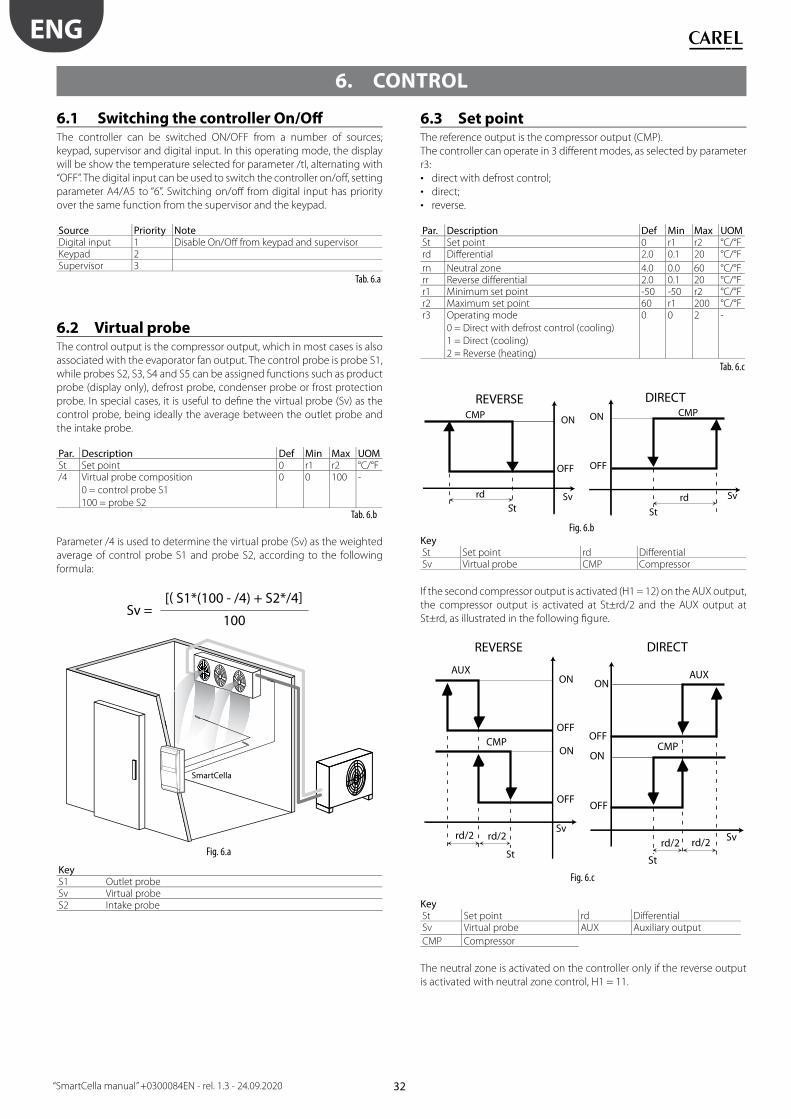
32
ENG
“SmartCella manual” +0300084EN - rel. 1.3 - 24.09.2020
6. CONTROL
6.1 Switching the controller On/Off The controller can be switched ON/OFF from a number of sources;
keypad, supervisor and digital input. In this operating mode, the display
will be show the temperature selected for parameter /tI, alternating with
“OFF”. The digital input can be used to switch the controller on/off , setting
parameter A4/A5 to “6”. Switching on/off from digital input has priority
over the same function from the supervisor and the keypad.
Source Priority NoteDigital input 1 Disable On/Off from keypad and supervisorKeypad 2Supervisor 3
Tab. 6.a
6.2 Virtual probeThe control output is the compressor output, which in most cases is also
associated with the evaporator fan output. The control probe is probe S1,
while probes S2, S3, S4 and S5 can be assigned functions such as product
probe (display only), defrost probe, condenser probe or frost protection
probe. In special cases, it is useful to defi ne the virtual probe (Sv) as the
control probe, being ideally the average between the outlet probe and
the intake probe.
Par. Description Def Min Max UOMSt Set point 0 r1 r2 °C/°F/4 Virtual probe composition
0 = control probe S1
100 = probe S2
0 0 100 -
Tab. 6.b
Parameter /4 is used to determine the virtual probe (Sv) as the weighted
average of control probe S1 and probe S2, according to the following
formula:
Sv = [( S1*(100 - /4) + S2*/4]
100
SmartCella
Fig. 6.a
KeyS1 Outlet probeSv Virtual probeS2 Intake probe
6.3 Set pointThe reference output is the compressor output (CMP).
The controller can operate in 3 diff erent modes, as selected by parameter
r3:
• direct with defrost control;
• direct;
• reverse.
Par. Description Def Min Max UOMSt Set point 0 r1 r2 °C/°Frd Diff erential 2.0 0.1 20 °C/°F
rn Neutral zone 4.0 0.0 60 °C/°Frr Reverse diff erential 2.0 0.1 20 °C/°Fr1 Minimum set point -50 -50 r2 °C/°Fr2 Maximum set point 60 r1 200 °C/°Fr3 Operating mode
0 = Direct with defrost control (cooling)
1 = Direct (cooling)
2 = Reverse (heating)
0 0 2 -
Tab. 6.c
ON
OFF
Sv
CMP
REVERSE
Strd
ON
OFF
Sv
CMP
Strd
DIRECT
Fig. 6.bKeySt Set point rd Diff erentialSv Virtual probe CMP Compressor
If the second compressor output is activated (H1 = 12) on the AUX output,
the compressor output is activated at St±rd/2 and the AUX output at
St±rd, as illustrated in the following fi gure.
ON
OFF
CMP
ON
OFF
Svrd/2
AUX
rd/2
REVERSE
St
ON
OFF
St
Svrd/2
CMP
ON
OFF
rd/2
AUX
DIRECT
Fig. 6.c
KeySt Set point rd Diff erentialSv Virtual probe AUX Auxiliary output
CMP Compressor
The neutral zone is activated on the controller only if the reverse output
is activated with neutral zone control, H1 = 11.
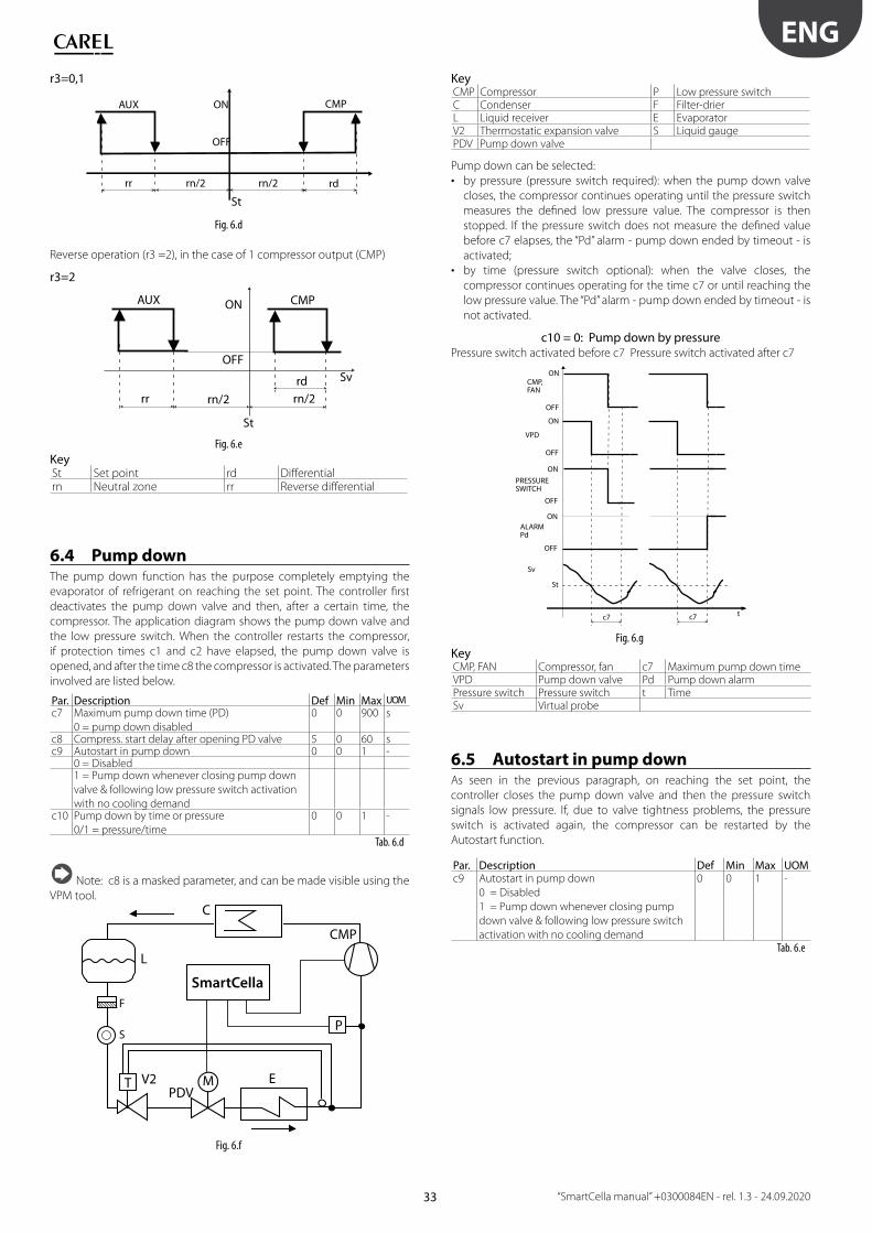
33
ENG
“SmartCella manual” +0300084EN - rel. 1.3 - 24.09.2020
r3=0,1
ON
OFF
CMP
rr rn/2 rn/2
AUX
rd
St
Fig. 6.d
Reverse operation (r3 =2), in the case of 1 compressor output (CMP)
r3=2
ON
OFF
CMP
rn/2
rd
AUX
rn/2rr
Sv
St
Fig. 6.e
KeySt Set point rd Diff erentialrn Neutral zone rr Reverse diff erential
6.4 Pump downThe pump down function has the purpose completely emptying the
evaporator of refrigerant on reaching the set point. The controller fi rst
deactivates the pump down valve and then, after a certain time, the
compressor. The application diagram shows the pump down valve and
the low pressure switch. When the controller restarts the compressor,
if protection times c1 and c2 have elapsed, the pump down valve is
opened, and after the time c8 the compressor is activated. The parameters
involved are listed below.
Par. Description Def Min Max UOM
c7 Maximum pump down time (PD)
0 = pump down disabled
0 0 900 s
c8 Compress. start delay after opening PD valve 5 0 60 sc9 Autostart in pump down 0 0 1 -
0 = Disabled1 = Pump down whenever closing pump down
valve & following low pressure switch activation
with no cooling demandc10 Pump down by time or pressure
0/1 = pressure/time
0 0 1 -
Tab. 6.d
Note: c8 is a masked parameter, and can be made visible using the
VPM tool.
C
L
PDVM
CMP
ET V2
P
SmartCella
S
F
Fig. 6.f
KeyCMP Compressor P Low pressure switchC Condenser F Filter-drierL Liquid receiver E EvaporatorV2 Thermostatic expansion valve S Liquid gaugePDV Pump down valve
Pump down can be selected:
• by pressure (pressure switch required): when the pump down valve
closes, the compressor continues operating until the pressure switch
measures the defi ned low pressure value. The compressor is then
stopped. If the pressure switch does not measure the defi ned value
before c7 elapses, the “Pd” alarm - pump down ended by timeout - is
activated;
• by time (pressure switch optional): when the valve closes, the
compressor continues operating for the time c7 or until reaching the
low pressure value. The “Pd” alarm - pump down ended by timeout - is
not activated.
c10 = 0: Pump down by pressurePressure switch activated before c7 Pressure switch activated after c7
ON
OFF
ON
OFF
t
CMP,FAN
VPD
c7
PRESSURESWITCH
St
ON
OFF
ALARM Pd
ON
OFF
Sv
c7
Fig. 6.g
KeyCMP, FAN Compressor, fan c7 Maximum pump down timeVPD Pump down valve Pd Pump down alarmPressure switch Pressure switch t TimeSv Virtual probe
6.5 Autostart in pump downAs seen in the previous paragraph, on reaching the set point, the
controller closes the pump down valve and then the pressure switch
signals low pressure. If, due to valve tightness problems, the pressure
switch is activated again, the compressor can be restarted by the
Autostart function.
Par. Description Def Min Max UOMc9 Autostart in pump down
0 = Disabled
1 = Pump down whenever closing pump
down valve & following low pressure switch
activation with no cooling demand
0 0 1 -
Tab. 6.e
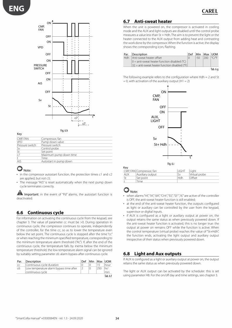
34
ENG
“SmartCella manual” +0300084EN - rel. 1.3 - 24.09.2020
ON
OFF
ON
OFF
t
CMP,FAN
VPD
c7
PRESSURESWITCH
St
ON
OFF
AtSON
OFF
Sv
c7
Fig. 6.hKey
CMP, FAN Compressor, fanVPD Pump down valvePressure switch Pressure switchSv Control probeSt Set pointc7 Maximum pump down timet TimeAtS Autostart in pump down
Note:
• in the compressor autostart function, the protection times c1 and c2
are applied, but not c3;
• The message “AtS” is reset automatically when the next pump down
cycle terminates correctly.
Important: in the event of “Pd” alarms, the autostart function is
deactivated.
6.6 Continuous cycleFor information on activating the continuous cycle from the keypad, see
chapter 3. The value of parameter cc must be >0. During operation in
continuous cycle, the compressor continues to operate, independently
of the controller, for the time cc, so as to lower the temperature even
below the set point. The continuous cycle is stopped after the time “cc”
or when reaching the minimum specifi ed temperature, corresponding to
the minimum temperature alarm threshold (“AL”). If, after the end of the
continuous cycle, the temperature falls by inertia below the minimum
temperature threshold, the low temperature alarm signal can be ignored
by suitably setting parameter c6: alarm bypass after continuous cycle.
Par. Description Def Min Max UOMcc Continuous cycle duration 0 0 15 hourc6 Low temperature alarm bypass time after
continuous cycle
2 0 250 hr/
min
Tab. 6.f
6.7 Anti-sweat heaterWhen the unit is powered on, the compressor is activated in cooling
mode and the AUX and light outputs are disabled until the control probe
measures a value less than St + Hdh. The aim is to prevent the light or the
heater connected to the AUX output from adding heat and contrasting
the work done by the compressor. When the function is active, the display
shows the corresponding icon, fl ashing.
Par. Description Def Min Max UOMHdh Anti-sweat heater off set
0 = anti-sweat heater function disabled (°C)
32 = anti-sweat heater function disabled (°F)
0 -50 200 °C/°F
Tab. 6.g
The following example refers to the confi guration where Hdh = 2 and St
= 0, with activation of the auxiliary output (H1 = 2)
CMP,FAN
St+ Hdh
AUX, LIGHT
ON
OFF
Sv
ON
OFF
t
Fig. 6.iKeyCMP, FAN Compressor, fan LIGHT LightAUX Auxiliary output Sv Virtual probeSt Set point Hdh Off sett Time
Note:
• when alarms “HI”, “IA”, “dA”, “CHt”, “EE”, “EF” ,”rE” are active of the controller
is OFF, the anti-sweat heater function is still enabled;
• at the end of the anti-sweat heater function, the outputs confi gured
as light or auxiliary can be controlled by the user from the keypad,
supervisor or digital inputs.
• if AUX is confi gured as a light or auxiliary output at power on, the
output retains the same status as when previously powered down. If
the anti-sweat heater function is activated, this is no longer true: the
output at power on remains OFF while the function is active. When
the control temperature (virtual probe) reaches the value of “St+Hdh”,
the function ends, activating the light output and auxiliary output
irrespective of their status when previously powered down.
6.8 Light and Aux outputsIf AUX is confi gured as a light or auxiliary output at power on, the output
retains the same status as when previously powered down.
The light or AUX output can be activated by the scheduler: this is set
using parameter H8. For the on/off day and time settings, see chapter 3.
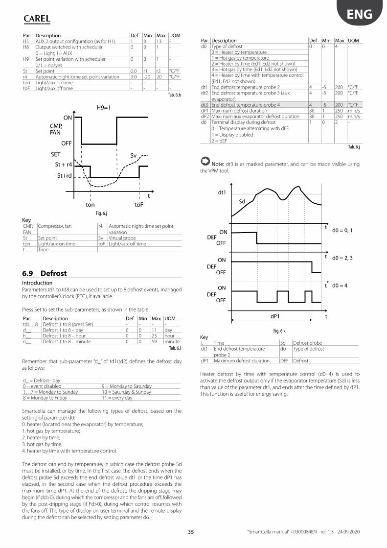
35
ENG
“SmartCella manual” +0300084EN - rel. 1.3 - 24.09.2020
Par. Description Def Min Max UOMH5 AUX 2 output confi guration (as for H1) 1 0 13 -H8 Output switched with scheduler
0 = Light; 1= AUX
0 0 1 -
H9 Set point variation with scheduler
0/1 = no/yes
0 0 1 -
St Set point 0.0 r1 r2 °C/°Fr4 Automatic night-time set point variation 3.0 -20 20 °C/°Fton Light/aux on time - - - -toF Light/aux off time - - - -
Tab. 6.h
t
SET
CMP,FAN
ON
OFF
ton toF
St+rd
St + r4Sv
H9=1
Fig. 6.j
KeyCMP,
FAN
Compressor, fan r4 Automatic night-time set point
variationSt Set point Sv Virtual probeton Light/aux on time toF Light/aux off timet Time
6.9 DefrostIntroductionParameters td1 to td8 can be used to set up to 8 defrost events, managed
by the controller’s clock (RTC), if available.
Press Set to set the sub-parameters, as shown in the table:
Par. Description Def Min Max UOMtd1…8 Defrost 1 to 8 (press Set) - - - -d__ Defrost 1 to 8 – day 0 0 11 dayh__ Defrost 1 to 8 – hour 0 0 23 hourn__ Defrost 1 to 8 – minute 0 0 59 minute
Tab. 6.i
Remember that sub-parameter “d_” of td1(td2) defi nes the defrost day
as follows:
d_ = Defrost– day0 = event disabled 9 = Monday to Saturday1…7 = Monday to Sunday 10 = Saturday & Sunday8 = Monday to Friday 11 = every day
Smartcella can manage the following types of defrost, based on the
setting of parameter d0:
0. heater (located near the evaporator) by temperature;
1. hot gas by temperature;
2. heater by time;
3. hot gas by time;
4. heater by time with temperature control.
The defrost can end by temperature, in which case the defrost probe Sd
must be installed, or by time. In the fi rst case, the defrost ends when the
defrost probe Sd exceeds the end defrost value dt1 or the time dP1 has
elapsed, in the second case when the defrost procedure exceeds the
maximum time dP1. At the end of the defrost, the dripping stage may
begin (if dd>0), during which the compressor and the fans are off , followed
by the post-dripping stage (if Fd>0), during which control resumes with
the fans off . The type of display on user terminal and the remote display
during the defrost can be selected by setting parameter d6.
Par. Description Def Min Max UOMd0 Type of defrost 0 0 4 -
0 = Heater by temperature1 = Hot gas by temperature2 = Heater by time (Ed1, Ed2 not shown)3 = Hot gas by time (Ed1, Ed2 not shown)4 = Heater by time with temperature control
(Ed1, Ed2 not shown)dt1 End defrost temperature probe 2 4 -5 200 °C/°Fdt2 End defrost temperature probe 3 (aux
evaporator)
4 -5 200 °C/°F
dt3 End defrost temperature probe 4 4 -5 200 °C/°FdP1 Maximum defrost duration 30 1 250 min/sdP2 Maximum aux evaporator defrost duration 30 1 250 min/sd6 Terminal display during defrost
0 = Temperature alternating with dEF
1 = Display disabled
2 = dEF
1 0 2 -
Tab. 6.j
Note: dt3 is as masked parameter, and can be made visible using
the VPM tool.
ON
OFFDEF
t
t
dt1
dP1
Sd
d0 = 0, 1
t
t
d0 = 2, 3
d0 = 4
ON
OFFDEF
ON
OFFDEF
Fig. 6.kKeyt Time Sd Defrost probedt1 End defrost temperature
probe 2
d0 Type of defrost
dP1 Maximum defrost duration DEF Defrost
Heater defrost by time with temperature control (d0=4) is used to
activate the defrost output only if the evaporator temperature (Sd) is less
than value of the parameter dt1, and ends after the time defi ned by dP1.
This function is useful for energy saving.
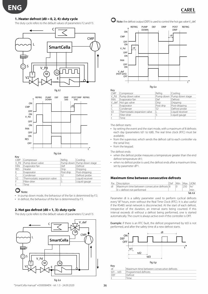
36
ENG
“SmartCella manual” +0300084EN - rel. 1.3 - 24.09.2020
1. Heater defrost (d0 = 0, 2, 4): duty cycleThe duty cycle refers to the default values of parameters F2 and F3.
C
L
CMP
TV2 E
S2M
V_Pd
SmartCella
S
F
Fig. 6.l
ON
OFFON
OFF
t
CMP
V_Pd
ON
OFF
FAN
ON
OFF
RES
REFRIG PUMP DOWN
DEF DRIP (dd)
POST DRIP (Fd)
REFRIG
c8
Fig. 6.mKeyCMP Compressor Refrig CoolingV_Pd Pump down valve Pump down Pump down stageFAN Evaporator fan Def DefrostRES Heater Drip DrippingE Evaporator Post drip Post-drippingC Condenser S2 Defrost probeV2 Thermostatic expansion valve L Liquid receiverF Filter-drier S Liquid gauget Time
Note:
• in pump down mode, the behaviour of the fan is determined by F2;
• in defrost, the behaviour of the fan is determined by F3.
2. Hot gas defrost (d0 = 1, 3): duty cycleThe duty cycle refers to the default values of parameters F2 and F3.
C
LCMP
TV2 E
S2
V_Pd
M
M
V_def
S
F
SmartCella
Fig. 6.n
Note: the defrost output (DEF) is used to control the hot gas valve V_def.
ON
OFFON
OFF
t
CMP
V_Pd
ON
OFF
FAN
ON
OFF
V_def(HOT GAS)
REFRIG PUMP DOWN
DEF DRIP POSTDRIP
REFRIG
c8
c8
Fig. 6.oKeyCMP Compressor Refrig CoolingV_Pd Pump down valve Pump down Pump down stageFAN Evaporator fan Def DefrostV_def Hot gas valve Drip DrippingE Evaporator Post drip Post-drippingC Condenser S2 Defrost probeV2 Thermostatic expansion valve L Liquid receiverF Filter-drier S Liquid gauget Time
The defrost starts:
• by setting the event and the start mode, with a maximum of 8 defrosts
each day (parameters td1 to td8). The real time clock (RTC) must be
available;
• from the supervisor, which sends the defrost call to each controller via
the serial line;
• from the keypad.
The defrost ends:
• when the defrost probe measures a temperature greater than the end
defrost temperature dt1;
• when no defrost probe is used, the defrost ends after a maximum time,
set by parameter dP1.
Maximum time between consecutive defrosts
Par. Description Def Min Max UOMdI Maximum time between consecutive defrosts
0 = defrost not performed
8 0 250 hr/
minTab. 6.k
Parameter dI is a safety parameter used to perform cyclical defrosts
every “dI” hours, even without the Real Time Clock (RTC). It is also useful
if the RS485 serial network is disconnected. At the start of each defrost,
irrespective of the duration, an interval starts being counted. If this
interval exceeds dI without a defrost being performed, one is started
automatically. The count is always active even if the controller is OFF.
Example: if there is an RTC fault, the defrost programmed by td3 is not
performed, and after the safety time dI a new defrost starts.
ON
OFFDEF
ttd1
td2
dI
td3
Fig. 6.pKeydI Maximum time between consecutive defroststd1…td3 Programmed defrostsDEF Defrostt Time
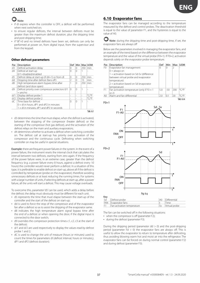
37
ENG
“SmartCella manual” +0300084EN - rel. 1.3 - 24.09.2020
Note:
• if dI expires when the controller is OFF, a defrost will be performed
when next switched on;
• to ensure regular defrosts, the interval between defrosts must be
greater than the maximum defrost duration, plus the dripping time
and post-dripping time;
• if “dI”=0 and no timed defrosts have been set, defrosts can only be
performed at power on, from digital input, from the supervisor and
from the keypad.
Other defrost parameters
Par. Description Def Min Max UOMd3 Defrost activation delay 0 0 250 mind4 Defrost at start-up
0/1=disabled/enabled
0 0 1 -
d5 Defrost delay at start-up (if d4=1) or from dI 0 0 250 mindd Dripping time after defrost (fans off ) 2 0 15 mind8 High temperature alarm bypass time after
defrost (and door open)
1 0 250 min
d9 Defrost priority over compressor protectors 0/1
= yes/no
0 0 1 -
d/1 Display defrost probe 1 - - - °C/°Fd/2 Display defrost probe 2 - - - °C/°FdC Time base for defrost
0 = dI in hours, dP1 and dP2 in minutes
1 = dI in minutes, dP1 and dP2 in seconds
0 0 1 -
Tab. 6.l
• d3 determines the time that must elapse, when the defrost is activated,
between the stopping of the compressor (heater defrost) or the
starting of the compressor (hot gas defrost), and the activation of the
defrost relays on the main and auxiliary evaporators;
• d4 determines whether to activate a defrost when switching controller
on. The defrost call at start-up has priority over activation of the
compressor and the continuous cycle. Defrosting when switching
controller on may be useful in special situations.
Example: there are frequent power failures in the system. In the event of a
power failure, the instrument resets the internal clock that calculates the
interval between two defrosts, starting from zero again. If the frequency
of the power failure were, in an extreme case, greater than the defrost
frequency (e.g. a power failure every 8 hours, against a defrost every 10
hours) the controller would never perform a defrost. In a situation of this
type, it is preferable to enable defrost on start-up, above all if the defrost is
controlled by temperature (probe on the evaporator), therefore avoiding
unnecessary defrosts or at least reducing the running times. For systems
with a large number of units, if selecting defrosts at start-up, after a power
failure, all the units will start a defrost. This may cause voltage overloads.
To overcome this, parameter ‘d5’ can be used, which adds a delay before
the defrost; the delay must obviously must be diff erent for each unit.
• d5 represents the time that must elapse between the start-up of the
controller and the start of the defrost on start-up;
• dd is used to force the stop of the compressor and of the evaporator
fan after a defrost so as to assist the dripping of the evaporator same.
• d8 indicates the high temperature alarm signal bypass time after
the end of a defrost or when opening the door, if the digital input is
connected to the door switch;
• d9 overrides the compressor protection times c1, c2, c3 at the start of
the defrost;
• d/1 and d/2 are used respectively to display the values read by defrost
probe 1 and 2;
• dC is used to change the unit of measure (hours or minutes) used to
count the times for parameters dI (defrost interval, hours or minutes,),
dP1 and dP2 (defrost duration).
6.10 Evaporator fansThe evaporator fans can be managed according to the temperature
measured by the defrost and control probes. The deactivation threshold
is equal to the value of parameter F1, and the hysteresis is equal to the
value of A0.
Note: during the dripping time and post-dripping time, if set, the
evaporator fans are always off
Below are the parameters involved in managing the evaporator fans, and
an example of the trend based on the diff erence between the evaporator
temperature and the value of the virtual probe (F0=1). If F0=2, activation
depends solely on the evaporator probe temperature.
Par. Description Def Min Max UOMF0 Evaporator fan management
0 = always on
1 = activation based on Sd-Sv (diff erence
between virtual probe and evaporator
temperature)
2 = activation based on Sd (evaporator
temperature)
0 0 2 -
F1 Fan activation temperature (only if F0 = 1
or 2)
5.0 -50 200 °C/°F
A0 Alarm and fan diff erential 2.0 0.1 20 °C/°F
Tab. 6.m
F0=1
ON
OFFFAN
F1Sd - Sv
F1-A0
t
t
F0=2
ON
OFFFAN
F1Sd
F1-A0
t
t
Fig. 6.qKeySd Defrost probe A0 Diff erentialFAN Evaporator fans t TimeF1 Fan activation temperature Sv Virtual probe
The fan can be switched off in the following situations:
• when the compressor is off (parameter F2);
• during the defrost (parameter F3).
During the dripping period (parameter dd > 0) and the post-dripping
period (parameter Fd > 0) the evaporator fans are always off . This is
useful to allow the evaporator to return to temperature after defrosting,
thus avoiding blowing warm hot and moist air into the refrigerator. The
evaporator fans can be forced on during normal control (parameter F2)
and during defrost (parameter F3).

38
ENG
“SmartCella manual” +0300084EN - rel. 1.3 - 24.09.2020
Par. Description Def Min Max UOMdd Dripping time after defrost (fans off ) 2 0 15 minF2 Evaporator fans with compressor off
0 = See F0
1 = Always off
1 0 1 -
F3 Evaporator fans during defrost
0/1=on/off
1 0 1 -
Fd Post-dripping time (fans off ) 1 0 15 min
Tab. 6.n
6.11 Condenser fansThe condenser fans are activated based on parameters F4 and F5.
After the compressor is fi rst started, the condenser fans are activated at
F4+0.2 degrees to off set any rapid temperature increases that the probe
cannot keep up with. Subsequently, the fans are switched on and off at
F4+F5 and F4.
Par. Description Def Min Max UOMF4 Condenser fan deactivation temperature 40 -50 200 °C/°FF5 Condenser fan activation diff erential 5.0 0.1 20 °C/°F
Tab. 6.o
ON
OFFFAN
F4 + F5Sc
F4F4 + 0.2
Firstswitch-on
t
t
Fig. 6.rKeySc Condenser probe Sv Virtual probeFAN Condenser fans t TimeF4 Deactivation temperature F5 Diff erential
Note: if no condenser probe is selected, the condenser fan output is
deactivated.
6.12 Duty setting (par. c4)If alarm “rE” (virtual control probe fault) is activated, this parameter is
used to ensure operation of the compressor until the fault is resolved.
As the compressor is no longer able to operate based according to the
temperature (due to the probe fault), it is made to run cyclically with a
running time equal to the value assigned to parameter c4 and a fi xed OFF
time of 15 minutes.
Par. Description Def Min Max UOMc4 Compressor running time with duty setting 0 0 100 min
ON
OFF
CMP
c4 15 t
Fig. 6.s
6.13 Running time defrost (par. d10, d11)Running time is a special function that determines when the refrigeration
unit needs defrosting. In particular, it is assumed that if the evaporator
temperature measured by probe Sd remains continuously below a
certain set threshold (d11) for a certain time (d10), the evaporator may
be frozen and a defrost is activated. The time is reset if the temperature
returns above the threshold.
Par. Description Def Min Max UOMd10 Defrost time in “Running time” mode
0 = function disabled
0 0 250 hour
d11 Running time defrost temperature threshold 1 -20 20 °C/°F
Tab. 6.q
ON
OFFDEF
d11
Sddt1
d10 t
t
Fig. 6.t
KeySd Defrost probe t timeDEF Defrost
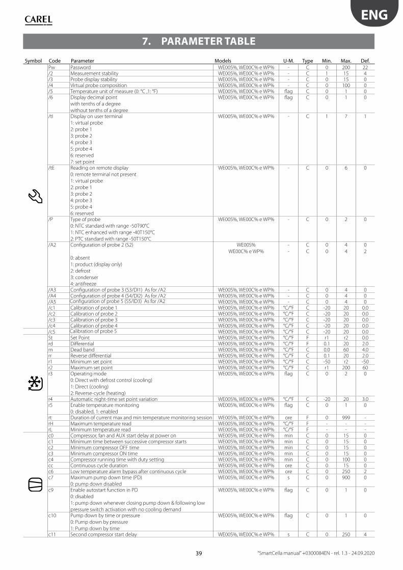
39
ENG
“SmartCella manual” +0300084EN - rel. 1.3 - 24.09.2020
7. PARAMETER TABLE
Symbol Code Parameter Models U-M. Type Min. Max. Def.
Pw Password WE00S%, WE00C% e WP% - C 0 200 22/2 Measurement stability WE00S%, WE00C% e WP% - C 1 15 4/3 Probe display stability WE00S%, WE00C% e WP% - C 0 15 0/4 Virtual probe composition WE00S%, WE00C% e WP% - C 0 100 0/5 Temperature unit of measure (0: °C ,1: °F) WE00S%, WE00C% e WP% fl ag C 0 1 0/6 Display decimal point
with tenths of a degree
without tenths of a degree
WE00S%, WE00C% e WP% fl ag C 0 1 0
/tI Display on user terminal
1: virtual probe
2: probe 1
3: probe 2
4: probe 3
5: probe 4
6: reserved
7: set point
WE00S%, WE00C% e WP% - C 1 7 1
/tE Reading on remote display
0: remote terminal not present
1: virtual probe
2: probe 1
3: probe 2
4: probe 3
5: probe 4
6: reserved
WE00S%, WE00C% e WP% - C 0 6 0
/P Type of probe
0: NTC standard with range -50T90°C
1: NTC enhanced with range -40T150°C
2: PTC standard with range -50T150°C
WE00S%, WE00C% e WP% - C 0 2 0
/A2 Confi guration of probe 2 (S2)
0: absent
1: product (display only)
2: defrost
3: condenser
4: antifreeze
WE00S%
WE00C% e WP%
-
-
C
C
0
0
4
4
0
2
/A3 Confi guration of probe 3 (S3/DI1) As for /A2 WE00S%, WE00C% e WP% - C 0 4 0/A4 Confi guration of probe 4 (S4/DI2) As for /A2 WE00S%, WE00C% e WP% - C 0 4 0/A5 Confi guration of probe 5 (S5/ID3) As for /A2 WE00S%, WE00C% e WP% - C 0 4 0/c1 Calibration of probe 1 WE00S%, WE00C% e WP% °C/°F C -20 20 0.0/c2 Calibration of probe 2 WE00S%, WE00C% e WP% °C/°F C -20 20 0.0/c3 Calibration of probe 3 WE00S%, WE00C% e WP% °C/°F C -20 20 0.0/c4 Calibration of probe 4 WE00S%, WE00C% e WP% °C/°F C -20 20 0.0/c5 Calibration of probe 5 WE00S%, WE00C% e WP% °C/°F C -20 20 0.0St Set Point WE00S%, WE00C% e WP% °C/°F F r1 r2 0.0rd Diff erential WE00S%, WE00C% e WP% °C/°F F 0.1 20 2.0rn Dead band WE00S%, WE00C% e WP% °C/°F C 0.0 60 4.0rr Reverse diff erential WE00S%, WE00C% e WP% °C/°F C 0.1 20 2.0r1 Minimum set point WE00S%, WE00C% e WP% °C/°F C -50 r2 -50r2 Maximum set point WE00S%, WE00C% e WP% °C/°F C r1 200 60r3 Operating mode
0: Direct with defrost control (cooling)
1: Direct (cooling)
2: Reverse-cycle (heating)
WE00S%, WE00C% e WP% fl ag C 0 2 0
r4 Automatic night-time set point variation WE00S%, WE00C% e WP% °C/°F C -20 20 3.0r5 Enable temperature monitoring
0: disabled, 1: enabled
WE00S%, WE00C% e WP% fl ag C 0 1 0
rt Duration of current max and min temperature monitoring session WE00S%, WE00C% e WP% ore F 0 999 -rH Maximum temperature read WE00S%, WE00C% e WP% °C/°F F - - -rL Minimum temperature read WE00S%, WE00C% e WP% °C/°F F - - -c0 Compressor, fan and AUX start delay at power on WE00S%, WE00C% e WP% min C 0 15 0c1 Minimum time between successive compressor starts WE00S%, WE00C% e WP% min C 0 15 0c2 Minimum compressor OFF time WE00S%, WE00C% e WP% min C 0 15 0c3 Minimum compressor ON time WE00S%, WE00C% e WP% min C 0 15 0c4 Compressor running time with duty setting WE00S%, WE00C% e WP% min C 0 100 0cc Continuous cycle duration WE00S%, WE00C% e WP% ore C 0 15 0c6 Low temperature alarm bypass after continuous cycle WE00S%, WE00C% e WP% ore C 0 250 2c7 Maximum pump down time (PD)
0: pump down disabled
WE00S%, WE00C% e WP% s C 0 900 0
c9 Enable autostart function in PD
0: disabled
1: pump down whenever closing pump down & following low
pressure switch activation with no cooling demand
WE00S%, WE00C% e WP% fl ag C 0 1 0
c10 Pump down by time or pressure
0: Pump down by pressure
1: Pump down by time
WE00S%, WE00C% e WP% fl ag C 0 1 0
c11 Second compressor start delay WE00S%, WE00C% e WP% s C 0 250 4
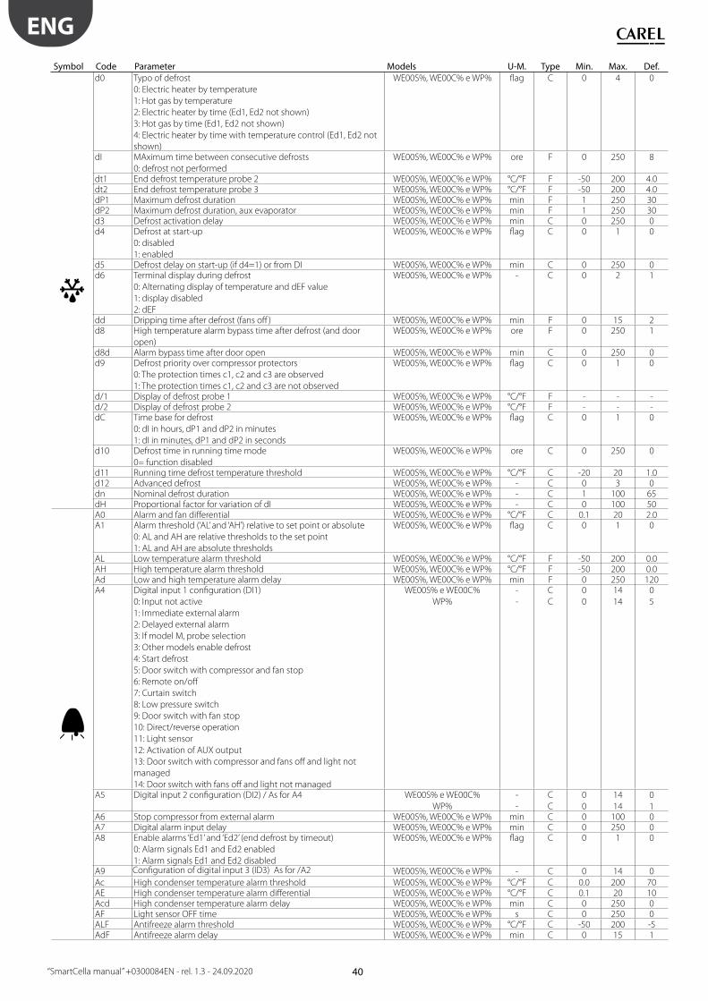
40
ENG
“SmartCella manual” +0300084EN - rel. 1.3 - 24.09.2020
Symbol Code Parameter Models U-M. Type Min. Max. Def.
d0 Typo of defrost
0: Electric heater by temperature
1: Hot gas by temperature
2: Electric heater by time (Ed1, Ed2 not shown)
3: Hot gas by time (Ed1, Ed2 not shown)
4: Electric heater by time with temperature control (Ed1, Ed2 not
shown)
WE00S%, WE00C% e WP% fl ag C 0 4 0
dI MAximum time between consecutive defrosts
0: defrost not performed
WE00S%, WE00C% e WP% ore F 0 250 8
dt1 End defrost temperature probe 2 WE00S%, WE00C% e WP% °C/°F F -50 200 4.0dt2 End defrost temperature probe 3 WE00S%, WE00C% e WP% °C/°F F -50 200 4.0dP1 Maximum defrost duration WE00S%, WE00C% e WP% min F 1 250 30dP2 Maximum defrost duration, aux evaporator WE00S%, WE00C% e WP% min F 1 250 30d3 Defrost activation delay WE00S%, WE00C% e WP% min C 0 250 0d4 Defrost at start-up
0: disabled
1: enabled
WE00S%, WE00C% e WP% fl ag C 0 1 0
d5 Defrost delay on start-up (if d4=1) or from DI WE00S%, WE00C% e WP% min C 0 250 0d6 Terminal display during defrost
0: Alternating display of temperature and dEF value
1: display disabled
2: dEF
WE00S%, WE00C% e WP% - C 0 2 1
dd Dripping time after defrost (fans off ) WE00S%, WE00C% e WP% min F 0 15 2d8 High temperature alarm bypass time after defrost (and door
open)
WE00S%, WE00C% e WP% ore F 0 250 1
d8d Alarm bypass time after door open WE00S%, WE00C% e WP% min C 0 250 0d9 Defrost priority over compressor protectors
0: The protection times c1, c2 and c3 are observed
1: The protection times c1, c2 and c3 are not observed
WE00S%, WE00C% e WP% fl ag C 0 1 0
d/1 Display of defrost probe 1 WE00S%, WE00C% e WP% °C/°F F - - -d/2 Display of defrost probe 2 WE00S%, WE00C% e WP% °C/°F F - - -dC Time base for defrost
0: dI in hours, dP1 and dP2 in minutes
1: dI in minutes, dP1 and dP2 in seconds
WE00S%, WE00C% e WP% fl ag C 0 1 0
d10 Defrost time in running time mode
0= function disabled
WE00S%, WE00C% e WP% ore C 0 250 0
d11 Running time defrost temperature threshold WE00S%, WE00C% e WP% °C/°F C -20 20 1.0d12 Advanced defrost WE00S%, WE00C% e WP% - C 0 3 0dn Nominal defrost duration WE00S%, WE00C% e WP% - C 1 100 65dH Proportional factor for variation of dI WE00S%, WE00C% e WP% - C 0 100 50A0 Alarm and fan diff erential WE00S%, WE00C% e WP% °C/°F C 0.1 20 2.0A1 Alarm threshold (‘AL’ and ‘AH’) relative to set point or absolute
0: AL and AH are relative thresholds to the set point
1: AL and AH are absolute thresholds
WE00S%, WE00C% e WP% fl ag C 0 1 0
AL Low temperature alarm threshold WE00S%, WE00C% e WP% °C/°F F -50 200 0.0AH High temperature alarm threshold WE00S%, WE00C% e WP% °C/°F F -50 200 0.0Ad Low and high temperature alarm delay WE00S%, WE00C% e WP% min F 0 250 120A4 Digital input 1 confi guration (DI1)
0: Input not active
1: Immediate external alarm
2: Delayed external alarm
3: If model M, probe selection
3: Other models enable defrost
4: Start defrost
5: Door switch with compressor and fan stop
6: Remote on/off
7: Curtain switch
8: Low pressure switch
9: Door switch with fan stop
10: Direct/reverse operation
11: Light sensor
12: Activation of AUX output
13: Door switch with compressor and fans off and light not
managed
14: Door switch with fans off and light not managed
WE00S% e WE00C%
WP%
-
-
C
C
0
0
14
14
0
5
A5 Digital input 2 confi guration (DI2) / As for A4 WE00S% e WE00C%
WP%
-
-
C
C
0
0
14
14
0
1A6 Stop compressor from external alarm WE00S%, WE00C% e WP% min C 0 100 0A7 Digital alarm input delay WE00S%, WE00C% e WP% min C 0 250 0A8 Enable alarms ‘Ed1’ and ‘Ed2’ (end defrost by timeout)
0: Alarm signals Ed1 and Ed2 enabled
1: Alarm signals Ed1 and Ed2 disabled
WE00S%, WE00C% e WP% fl ag C 0 1 0
A9 Confi guration of digital input 3 (ID3) As for /A2 WE00S%, WE00C% e WP% - C 0 14 0Ac High condenser temperature alarm threshold WE00S%, WE00C% e WP% °C/°F C 0.0 200 70AE High condenser temperature alarm diff erential WE00S%, WE00C% e WP% °C/°F C 0.1 20 10Acd High condenser temperature alarm delay WE00S%, WE00C% e WP% min C 0 250 0AF Light sensor OFF time WE00S%, WE00C% e WP% s C 0 250 0ALF Antifreeze alarm threshold WE00S%, WE00C% e WP% °C/°F C -50 200 -5AdF Antifreeze alarm delay WE00S%, WE00C% e WP% min C 0 15 1

41
ENG
“SmartCella manual” +0300084EN - rel. 1.3 - 24.09.2020
Symbol Code Parameter Models U-M. Type Min. Max. Def.
F0 Evaporator fan management
0: always on
1: Activation based on Sd-Sv ( diff erence between virtual probe
and evaporator temperature)
2: Activation based on Sd (evaporator temperature)
WE00C% e WP% fl ag C 0 2 0
F1 Fan activation temperature (only if F0= 1 or 2) WE00C% e WP% °C/°F F -50 200 5F2 Evaporator fans with compressor OFF
0: see F0
1: always off
WE00C% e WP% fl ag C 0 1 1
F3 Evaporator fans during defrost
0: Fans operate
1: Fans do not operate
WE00C% e WP% fl ag C 0 1 1
Fd Post dripping time (fans OFF) WE00C% e WP% min F 0 15 1F4 Condenser fan stop temperature WE00C% e WP% °C/°F C -50 200 40F5 Condenser fan start diff erential WE00C% e WP% °C/°F C 0.1 20 5H0 Serial address WE00S%, WE00C% e WP% - C 0 207 1H1 AUX1 output confi guration
0: normally energised alarm
1: normally de-energised alarm
2: Auxiliary
3: Light
4: Auxiliary evaporator defrost
5: Pump down valve
6: Condenser fan
7: Delayed compressor
8: Auxiliary with deactivation when OFF
9: Light with deactivation when OFF
10: No function
11: Reverse with neutral zone
12: Second compressor step
13: Second compressor step with rotation
WE00C%
WP%
fl ag
fl ag
C
C
0
0
13
13
1
3
H2 Disable keypad/ir
Pa
ram
ete
r “H
2”
LIG
HT
ON
/OF
F
AU
X
HA
CC
P
PR
G/M
UT
E (
mu
te)
UP
/CC
DO
WN
/DE
F
SE
T
pa
ram
ete
r F
mo
difi
ca
tio
n
Se
t p
oin
t m
od
ifi c
ati
on
0 • •12 • •34 • • • •5 • • • • •6 • • • •Keypad function"•" = Disabled
WE00S%, WE00C% e WP% fl ag C 0 6 1
H3 not user - C 0 255 0H4 Buzzer
0: enabled
1: disabled
WE00S%, WE00C% e WP% fl ag C 0 1 0
H5 AUX 2 output confi guration (as for H1) WE00C% - WP% fl ag 1 0 13 -H6 Terminal keypad lock confi guration WE00S%, WE00C% e WP% - C 0 255 0H8 Output switched with scheduler
0: light - 1: Aux
WE00S%, WE00C% e WP% fl ag C 0 1 0
H9 Set point variation with time band
0: Set point variation with time band disabled
1: Set point variation with time band enabled
WE00S%, WE00C% e WP% fl ag C 0 1 0
Hdh Anti-sweat heater off set WE00S%, WE00C% e WP% °C/°F C -50 200 0HAn Number of HA alarms WE00C2HC% - C 0 15 0HA...HA2
y__
M__
d__
h__
n__
t__
HA HACCP alarms activated (press Set)
Year
Month
Day
Hour
Minute
Duration
WE00C2HC% -
years
months
days
hours
min.
hours
C
0
1
1
0
0
0
-
99
12
7
23
59
99
-
0
0
0
0
0
0HFn Number of HF alarms WE00C2HC% - C 0 15 0HF...HF2
y__
M__
d__
h__
n__
t__
Date/time of last HF event
Year
Month
Day
Hour
Minute
Duration
WE00C2HC% -
years
months
days
hours
min.
hours
C
0
1
1
0
0
0
-
99
12
7
23
59
99
-
0
0
0
0
0
0Htd HACCP alarm delay WE00C2HC% min C 0 250 0

42
ENG
“SmartCella manual” +0300084EN - rel. 1.3 - 24.09.2020
Symbol Code Parameter Models U-M. Type Min. Max. Def.
td1...8
d__
h__
n__
Defrost 1...8 (press Set)
Day
Hour
Minute
WE00C2HC% -
days
hours
min.
C -
0
0
0
-
11
23
59
-
0
0
0ton
d__
h__
n__
Light/aux on time
Day
Hour
Minute
WE00C2HC% -
days
hours
min.
C -
0
0
0
-
11
23
59
-
0
0
0toF
d__
h__
n__
Light/aux off time
Day
Hour
Minute
WE00C2HC% -
days
hours
min.
C -
0
0
0
-
11
23
59
-
0
0
0tc
y__
M__
d__
u__
h__
n__
RTC date/time
Year
Month
Days of month
Days of week
Hours
Minute
WE00C2HC% -
years
months
days
days
hours
min.
-
0
1
1
1
0
0
-
99
12
31
7
23
59
-
0
1
1
6
0
0Tab. 7.a
7.14 Variables only accessible via serial
connection
Description Type CAREL SVP Modbus R/WVirtual probe A 3 3 RProbe 1 reading A 4 4 RProbe 2 reading A 5 5 RProbe 3 reading A 6 6 RProbe 4 reading A 7 7 RNumber of parameter sets available I 137 237 RDigital input 1 status D 6 6 RDigital input 2 status D 7 7 RVirtual probe fault alarm D 9 9 RProbe alarm 1 D 10 10 RProbe alarm 2 D 11 11 RProbe alarm 3 D 12 12 RProbe alarm 4 D 13 13 RCompressor status relay D 1 1 RDefrost relay status D 2 2 RFan relay status D 3 3 RAUX relay status D 4 4 RDigital input 1 status D 6 6 RDigital input 2 status D 7 7 RDefrost status D 31 31 RDefrost call command D 34 34 RWContinuous cycle status D 35 35 RContinuous cycle call command D 36 36 RWDoor status D 37 37 RAUX activation command D 57 57 RWLight activation command D 58 58 RWController ON/OFF D 59 59 RWPassword I 14 114 RWVirtual probe fault alarm D 9 9 RProbe 1/2/3/4/5 fault alarm D 10/11/12/13/14 10/11/12/13/14 RLow temperature alarm D 15 15 RHigh temperature alarm D 16 16 RImmediate external alarm D 17 17 RDelayed external alarm D 18 18 REvaporator 1 defrost timeout alarm D 19 19 REvaporator 2 defrost timeout alarm D 20 20 RPump down timeout alarm D 21 21 RLow pressure alarm D 21 21 RHigh condenser temperature alarm D 24 24 RDoor open for too long alarm D 25 25 RRTC error D 26 26 RControl parameter EEPROM error D 27 27 ROperating parameter EEPROM error D 28 28 RHA HACCP alarm D 29 29 RHF HACCP alarm D 30 30 RAlarm autostart in pump down D 32 32 R
Tab. 7.b
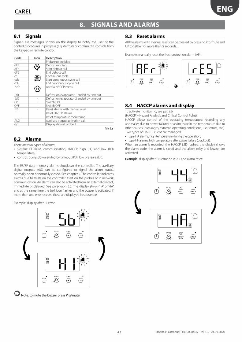
43
ENG
“SmartCella manual” +0300084EN - rel. 1.3 - 24.09.2020
8. SIGNALS AND ALARMS
8.1 SignalsSignals are messages shown on the display to notify the user of the
control procedures in progress (e.g. defrost) or confi rm the controls from
the keypad or remote control.
Code Icon Description--- - Probe not enableddEF
Defrost runningdFb Start defrost calldFE End defrost callcc
Continuous cycleccb Start continuous cycle callccE End continuous cycle callHcP
Access HACCP menu
Ed1 - Defrost on evaporator 1 ended by timeoutEd2 - Defrost on evaporator 2 ended by timeoutOn - Switch ONOFF - Switch OFFrES - Reset alarms with manual reset
Reset HACCP alarms
Reset temperature monitoringAUX - Auxiliary output activation calld/1 Display defrost probe 1
Tab. 8.a
8.2 AlarmsThere are two types of alarms:
• system: EEPROM, communication, HACCP, high (HI) and low (LO)
temperature;
• control: pump down ended by timeout (Pd), low pressure (LP).
The EE/EF data memory alarms shutdown the controller. The auxiliary
digital outputs AUX can be confi gured to signal the alarm status,
normally open or normally closed. See chapter 5. The controller indicates
alarms due to faults on the controller itself, on the probes or in network
communication. An alarm can also be activated from an external contact,
immediate or delayed. See paragraph 5.2. The display shows “IA” or “dA”
and at the same time the bell icon fl ashes and the buzzer is activated. If
more than one error occurs, these are displayed in sequence.
Example: display after HI error:
Note: to mute the buzzer press Prg/mute.
8.3 Reset alarmsAll the alarms with manual reset can be cleared by pressing Prg/mute and
UP together for more than 5 seconds.
Example: manually reset the frost protection alarm (AFr).
8.4 HACCP alarms and displayTo activate monitoring, see par. 8.6.
(HACCP = Hazard Analysis and Critical Control Point).
HACCP allows control of the operating temperature, recording any
anomalies due to power failures or an increase in the temperature due to
other causes (breakages, extreme operating conditions, user errors, etc.).
Two types of HACCP event are managed:
• type HA alarms, high temperature during the operation;
• type HF alarms, high temperature after power failure (blackout).
When an alarm is recorded, the HACCP LED fl ashes, the display shows
the alarm code, the alarm is saved and the alarm relay and buzzer are
activated.
Example: display after HA error on ir33+ and alarm reset:

44
ENG
“SmartCella manual” +0300084EN - rel. 1.3 - 24.09.2020
To display the HA and HF alarms:
• enter the HACCP menu by pressing +
• scroll the list of alarms by pressing UP and DOWN;
• press Set to select the required alarm (HA, HA1, HA2/HF, HF1, HF2);
• use UP or DOWN to see the description of the alarm: year, month, day,
hours, minutes and duration in minutes of the selected alarm;
• press Prg/mute again to return to the previous list.
In addition, the HACCP alarm menu allows the following operations:
• delete the HACCP alarm signal by pressing, for 5 seconds:
+
• delete the HACCP alarm and all the alarms saved by pressing, for 5
seconds + +
This procedure displays the message rES, deletes the entire memory of
alarms and reinitialises monitoring of the HACCP alarms.

45
ENG
“SmartCella manual” +0300084EN - rel. 1.3 - 24.09.2020
8.4
.1
Ta
ble
of
ala
rm s
ign
als
Co
de
on
dis
pla
y
Ca
use
of
the
ala
rmIc
on
fl a
shin
g
on
dis
pla
y
Ala
rm
rela
y
Bu
zze
rR
ese
tP
D v
alv
eC
om
pre
sso
rD
efr
ost
Eva
po
rato
r
fan
s
Co
nd
en
ser
fan
sC
on
tin
uo
us
cycl
e
AU
X n
eu
tra
l
zon
e
AU
X li
gh
t
An
ti-s
we
at
AU
X a
uxi
liary
An
ti-s
we
at
AU
X s
eco
nd
ste
p
rEV
irtu
al c
on
tro
l pro
be
fau
lt
ON
ON
auto
m.
du
ty s
ett
ing
(c4
)d
uty
se
ttin
g (
c4)
--
--
OFF
OFF
OFF
du
ty s
ett
ing
(c4
)
E0P
rob
e S
1 f
ault
OFF
OFF
auto
m.
du
ty s
ett
ing
(c4
)
du
ty s
ett
ing
(c4
)-
--
-O
FFO
FFO
FFd
uty
se
ttin
g
(c4
)
E1P
rob
e S
2 f
ault
OFF
OFF
auto
mat
ic-
--
--
--
--
-
E2P
rob
e S
3 f
ault
OFF
OFF
auto
m.
--
--
--
--
--
E3P
rob
e S
4 f
ault
OFF
OFF
auto
m.
--
--
--
--
--
LOLo
w t
em
pe
ratu
re a
larm
ON
ON
auto
m.
--
--
--
--
--
HI
Hig
h t
em
pe
ratu
re a
larm
ON
ON
auto
m.
--
--
--
-O
FFO
FF-
AFr
Fro
st p
rote
ctio
n a
larm
ON
ON
man
ual
OFF
OFF
--
--
--
-O
FF
IAIm
me
dia
te a
larm
fro
m e
xte
rnal
con
tact
ON
ON
auto
mat
icd
uty
se
ttin
g (A
6)
du
ty s
ett
ing
(A6
)-
--
-O
FFO
FFO
FFd
uty
se
ttin
g (A
6)
dA
De
laye
d a
larm
fro
m e
xte
rnal
co
nta
ct
ON
ON
auto
mat
icd
uty
se
ttin
g (A
6)
--
--
-O
FF if
A7
≠0
OFF
if A
7≠
0O
FF if
A7
≠0
du
ty s
ett
ing
(A6
) if
A7
≠0
PdA
larm
max
imu
m p
um
p d
ow
n t
ime
ON
ON
auto
mat
ic/
man
ual
--
--
--
--
--
LPLo
w p
ress
ure
ala
rm
ON
ON
auto
mat
ic/
man
ual
OFF
OFF
--
--
--
-O
FF
AtS
Au
tost
art
in p
um
p d
ow
n
ON
ON
auto
mat
ic/
man
ual
--
--
--
--
--
cht
Hig
h c
on
de
nse
r te
mp
. pre
-ala
rm-
OFF
OFF
auto
mat
ic/
man
ual
--
--
--
--
--
CH
tH
igh
co
nd
en
ser
tem
pe
ratu
re a
larm
ON
ON
man
ual
OFF
OFF
--
--
-O
FFO
FFO
FF
do
rD
oo
r o
pe
n fo
r to
o lo
ng
ala
rm
ON
ON
auto
mat
ic-
--
--
--
--
-
Etc
Re
al t
ime
clo
ck f
ault
OFF
OFF
auto
mat
icO
FFO
FFn
ot
run
OFF
OFF
no
t ru
nO
FFO
FFO
FFO
FF
EEU
nit
par
ame
ter
EEP
RO
M e
rro
r
OFF
OFF
auto
mat
icO
FFO
FFn
ot
run
OFF
OFF
no
t ru
nO
FFO
FFO
FFO
FF
EFO
pe
rati
ng
par
ame
ter
EEP
RO
M e
rro
r
OFF
OFF
auto
mat
icO
FFO
FFn
ot
run
OFF
OFF
no
t ru
nO
FFO
FFO
FFO
FF
HA
Typ
e o
f H
A H
AC
CP
ala
rm
OFF
OFF
man
ual
--
--
--
--
--
HF
Typ
e o
f H
F H
AC
CP
ala
rm
OFF
OFF
man
ual
--
--
--
--
--
n1
...n
6In
dic
ate
s al
arm
on
un
it 1
...6
in t
he
ne
two
rk
ON
ON
auto
mat
ic-
--
--
--
--
-
Tab.
8.b

46
ENG
“SmartCella manual” +0300084EN - rel. 1.3 - 24.09.2020
8.5 Alarm parametersAlarm parameters and activationAAL (AH) is used to determine the activation threshold for the low (high)
temperature alarm LO (HI). The value set for AL (AH) is continuously
compared against the value measured by the control probe. Parameter
Ad represents the alarm activation delay, in minutes; the low temperature
alarm (LO) is activated only if the temperature remains below the value
of AL for a time greater than Ad. The alarm may relative or absolute,
depending on the value of parameter A1. In the former case (A1=0),
the value of AL indicates the deviation from the set point and thus the
activation point for the low temperature alarm is: set point - AL. If the
set point changes, the activation point also changes automatically. In the
latter case (A1=1), the value of AL indicates the low temperature alarm
threshold. The low temperature alarm active is signalled by the buzzer
and LO shown on the display. The same applies to the high temperature
alarm (HI), with AH instead of AL.
Par Description Def Min Max UOMA0 Alarm and fan diff erential 2.0 0.1 20.0 °C/°FA1 Alarm thresholds (AL, AH) relative to set
point or absolute
0/1=relative/absolute
0 0 1 -
AL Low temperature alarm threshold
If A1= 0, AL=0: alarm disabled
If A1= 1, AL=-50: alarm disabled
0 -50.0 200 °C/°F
AH High temperature alarm threshold
If A1= 0, AL=0: alarm disabled
If A1= 1, AL=200: alarm disabled
0 -50.0 200 °C/°F
Ad High and low temperature alarm delay 120 0 250 minA6 Stop compressor on external alarm
0 = compressor always off ;
100 = compressor always on
0 0 100 min
A7 Digital alarm input delay
0 = control outputs unchanged
0 0 250 min
Tab. 8.c
Note:
• alarms LO and HI have automatic reset. A0 represents the hysteresis
between the alarm activation value and deactivation value;
• if Prg/mute is pressed when the value measured is above one of the
thresholds, the buzzer is immediately muted, while the alarm code
and the alarm output, if set, remain active until the value measured
is outside of the activation threshold. For delayed alarms from digital
input (A4=2, code dA), the contact must remain open for a time greater
than A7. In the case of an alarm event, a counter starts and generates
an alarm when reaching the minimum time A7. If during the count
the value measured returns within the threshold or the contact closes,
the alarm is not signalled and the count is reset. When a new alarm
condition occurs, the count starts from 0 again. Parameter A6 has a
similar meaning to parameter c4 (duty setting). If an external alarm
occurs (immediate or delayed) the compressor works for a time equal
to the value set for A6 and remains off for a fi xed time of 15 minutes.
OFF
AL
S1A0
LO HI
A0
AH
ON
ALARM
Fig. 8.a
KeyLO Low temperature alarm S1 Control probeHI High temperature alarm
8.6 HACCP alarm parameters and
monitoringHA alarmsThe alarm queue can be displayed by accessing parameters HA to
HA2. The type HA alarm is generated if during normal operation the
temperature read by the control probe exceeds the high temperature
threshold for the time Ad+Htd. Consequently, compared to the normal
high temperature alarm already signalled by the controller, the type HA
HACCP alarm is delayed by a further time Htd specifi cally for HACCP
recording. The order of alarms listed is progressive, HA is the most recent
alarm. A maximum of 3 errors are saved, in a FIFO list (HA to HA2): FIFO
(First In First Out) management means the fi rst error recorded is the fi rst
to be cancelled when the list is full and needs to be updated. The last
error saved is displayed for parameter HA. HAn indicates the number of
type HA alarms activated.
Par. Description Def Min Max UOMHAn Number of HA alarms 0 0 15 -HA…HA2 HA HACCP alarms activated (press
Set)
- - - -
y__ Alarm 1 to 3 - Year 0 0 99 yearM__ Alarm 1 to 3 - Month 0 1 12 monthd__ Alarm 1 to 3 – Day of the month 0 1 31 dayh__ Alarm 1 to 3 – Hour 0 0 23 hourn__ Alarm 1 to 3 – Minute 0 0 59 minute--- Alarm 1 to 3 – Duration 0 0 240 hourHtd HACCP alarm delay
0 = Monitoring disabled
0 0 240 min
Tab. 8.d
ON
OFFALARM
St
AH
Ad Htd
Sv
t
t
Fig. 8.b
KeyS1 Virtual probe Ad High and low temperature
alarm delaySt Set point Htd HACCP alarm delay
0 = monitoring disabledAH High temperature alarm
threshold
t Time
ALARM HA HACCP alarm
HF alarms
The type HF HACCP alarm is generated following a power failure for an
extended time (> 1 minute), if when power returns the temperature read
by the control probe exceeds the AH high temperature threshold. HFn
indicates the number of type HF alarms activated.
Par. Description Def Min Max UOMHFn Number of HF alarms 0 0 15 -HF…HF2 HF HACCP alarms activated (press Set) - - - -y__ Alarm 1 to 3 - Year 0 0 99 yearM__ Alarm 1 to 3 - Month 0 1 12 monthd__ Alarm 1 to 3 – Day of the month 0 1 31 dayh__ Alarm 1 to 3 – Hour 0 0 23 hourn__ Alarm 1 to 3 – Minute 0 0 59 minute
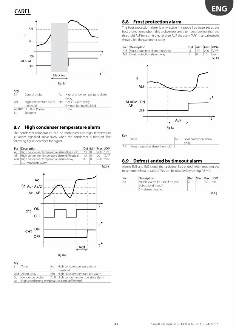
47
ENG
“SmartCella manual” +0300084EN - rel. 1.3 - 24.09.2020
ON
OFF
ALARM
t
St
AH
black out
S1
t
Fig. 8.c
KeyS1 Control probe Ad High and low temperature alarm
delayAH High temperature alarm
threshold
Htd HACCP alarm delay
0 = monitoring disabledALARM HF HACCP alarm t TimeSt Set point
8.7 High condenser temperature alarmThe condenser temperature can be monitored and high temperature
situations signalled, most likely when the condenser is blocked. The
following fi gure describes the signal.
Par Description Def Min Max UOMAc High condenser temperature alarm threshold 70 0 200 °C/°FAE High condenser temperature alarm diff erential 10 0.1 20 °C/°FAcd High condenser temperature alarm delay
0 = Immediate alarm
0 0 250 min
Tab. 8.e
ON
OFFcht
Ac - AE
Sc Ac - AE/2
Ac
OFFCHT
ON
t
t
t
Acd
Fig. 8.d
Keyt Time Ac High cond. temperature alarm
thresholdAcd Alarm delay cht High cond. temperature pre-alarmSc Condenser probe CHT High condensing temperature alarmAE High condensing temperature alarm diff erential
8.8 Frost protection alarmThe frost protection alarm is only active if a probe has been set as the
frost protection probe. If this probe measures a temperature less than the
threshold ALF for a time greater than AdF, the alarm “AFr” (manual reset) is
shown. See the parameter table.
Par Description Def Min Max UOMALF Frost protection alarm threshold -5 -50 200 °C/°FAdF Frost protection alarm delay 1 0 15 min
Tab. 8.f
ON
OFF
ALARM AFr
ALF
S
t
t
AdF
Fig. 8.e
Keyt Time AdF Frost protection alarm
delayAFr Frost protection alarm threshold
8.9 Defrost ended by timeout alarmAlarms Ed1 and Ed2 signal that a defrost has ended when reaching the
maximum defrost duration. This can be disabled by setting A8 = 0.
Par Description Def Min Max UOMA8 Enable alarms Ed1 and Ed2 (end
defrost by timeout)
0 = alarms disabled
0 0 250 min
Tab. 8.g

48
ENG
“SmartCella manual” +0300084EN - rel. 1.3 - 24.09.2020
9. TECHNICAL SPECIFICATIONS
9.1 Technical specifi cations
Single-phase version
Power supply Model Voltage PowerE 230 V~ (+10%, -15%), 50/60 Hz 3 VA, 25 mA~ max.A 115 V~, (+10%, -15%) 50/60 Hz 3 VA, 50 mA~ max.H 115...230 V~ (+10%, -15%), 50/60 Hz 6 VA, 50 mA~ max.L 12...24 V~ (+10%, -15%), 50/60 Hz, 12...30 Vdc 3 VA, 300 mA~ /mAdc max.0 12 V~, 50/60 Hz, 12...18 Vdc Only use TRA12VDE00 fuse transformer in the late 315 mA delayed
Insulation guaranteed by
the power supply E, A, Hinsulation from extra low voltage parts reinforced, 6 mm clearance, 8 mm creepage, 3750V insulationinsulation from relay outputs basic, 3 mm clearance, 4 mm creepage, 1250V insulation
0, Linsulation from extra low voltage parts to be guaranteed externally by safety transformer (SELV)insulation from relay outputs reinforced, 6 mm clearance, 8 mm creepage, 3750 V insulation
Inputs S1 (probe 1) NTCS2 (probe 2) NTCDI1 S3 (probe 3) voltage-free contact, contact resistance < 10 Ω, closing current 6 mA/ NTCDI2 S4 (probe 4) voltage-free contact, contact resistance < 10 Ω, closing current 6 mA/ NTCMaximum distance between probes and digital inputs less than 10 m. Note: in the installation it is recommended to separate the
power and load connections from the probe, digital input, display and supervisor cables.
Probe type
Std. Carel NTC10 kΩ a 25 °C, range –50T90 °Cmeasurement
error:
1 °C in the range -50T50 °C3 °C in the range 50T90 °C
High temperature NTC50 kΩ a 25 °C, range -40T150 °Cmeasurement
error:
1,5 °C in the range -20T115 °C4 °C in the range outside of -20T115 °C
Relay
outputs
depending on the model
EN60730-1 UL873relè 250 V~ operating cycles 250 V~ cicli manovra 8 A(*) 8(4)A on N.O.
6(4)A on N.C.
2(2)A on N.O. and N.C.
100000 8 A res. 2 FLA 12 LRA C300 30000
16 (*) 10(4) A to 60 °C on N.O.
12(2)A on N.O. and N.C.
100000 12 A res. 5 FLA 30 LRA C300 30000
2 Hp 10(10)A 100000 12 A res. 12 FLA 72 LRA C300 30000(*): Relay not suitable for fl uorescent loads (neon lights, etc.) that use starters (ballasts) with phase shifting capacitors. Fluorescent lamps with
electronic controllers or without phase shifting capacitors can be used, depending on the operating limits specifi ed for each type of relay.insulation from extra low voltage parts reinforced, 6 mm clearance, 8 mm creepage, 3750 V insulationinsulation between independent relay outputs basic, 3 mm clearance, 4 mm creepage, 1250 V insulation
Connections Cable cross-section from 0.5 to 2.5 mm2 max current 12 A
connection type section Maximum currentfi xed screw connectors
removable connectors for screw blocks
0,5 - 2,5 mq 12 A
conductor section for probes/digital inputs 0,5 - 2,5 mq da 20 a 13 AWGconductor section for power supplys/loads 0,5 - 2,5 mq da 15 a 13 AWG
The correct sizing of the power and connection cables between the instrument and the loads is the installer’s responsibility. Depending
on the model, the maximum current at common terminals 1, 3 or 5 is 12 A. If using the controller at maximum operating temperature
and at full load, the cables used must be suitable for operation at least up to 105 °C.Case plastic dimensions 128x290x101 mmDisplay digit 3 digit LED
display da -99 a 999 functioning mode showned with graphic icons on display
Keypad 4 buttons keppad membraneBuzzer available on all modelsOperating temperature models 0,L,H -10T50 °C
models E,A -10T45°C Operating humidity <90% U.R. no condensingStorage temperature -20T70 °CStorage humidity <90% U.R. no condensing Front panel degree of protection IP65 on the frontalControl pollution status 2 (in normal) PTI of insulating materials plastic molds 250 plastic and insulating materials 175Period of stress across the insulating parts longHeat and fi re resistance category category D e category B (UL 94-V0) Class of protection against voltage surge category IIType of action and disconnection 1.B relay contact (micro-switching) Construction of control Built-in, electronicClassifi cation according to protection against electric shock Class II, by suitable incorporationDevice to be hand-held or incorporated into equipment intended to be
manually held
no
Software class and structure classe AFrontal Cleaning of the controller Use only neutral detergents and water.Serial interface CARELnetwork extern. Available on all models, upon requestInterface for per display repeater extern. Available on models H, L, 0 upon requestMaximum distance between interface and display 10 mProgramming key available on alls modelsSafety standards: compliant with relevant European standards
Tab. 9.a
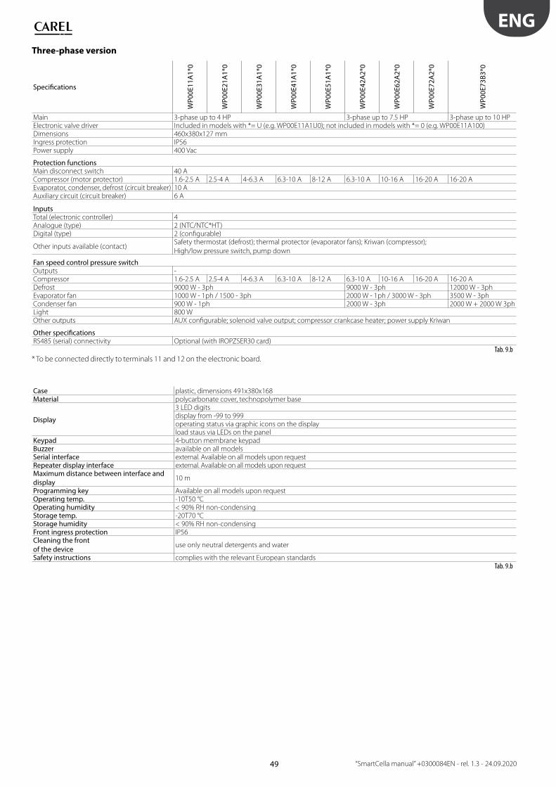
49
ENG
“SmartCella manual” +0300084EN - rel. 1.3 - 24.09.2020
Three-phase version
Specifi cations
WP
00
E1
1A
1*0
WP
00
E2
1A
1*0
WP
00
E3
1A
1*0
WP
00
E4
1A
1*0
WP
00
E5
1A
1*0
WP
00
E4
2A
2*0
WP
00
E6
2A
2*0
WP
00
E7
2A
2*0
WP
00
E7
3B
3*0
Main 3-phase up to 4 HP 3-phase up to 7.5 HP 3-phase up to 10 HPElectronic valve driver Included in models with *= U (e.g. WP00E11A1U0); not included in models with *= 0 (e.g. WP00E11A100)Dimensions 460x380x127 mmIngress protection IP56Power supply 400 Vac
Protection functionsMain disconnect switch 40 ACompressor (motor protector) 1.6-2.5 A 2.5-4 A 4-6.3 A 6.3-10 A 8-12 A 6.3-10 A 10-16 A 16-20 A 16-20 AEvaporator, condenser, defrost (circuit breaker) 10 AAuxiliary circuit (circuit breaker) 6 A
InputsTotal (electronic controller) 4Analogue (type) 2 (NTC/NTC*HT)Digital (type) 2 (confi gurable)
Other inputs available (contact)Safety thermostat (defrost); thermal protector (evaporator fans); Kriwan (compressor);
High/low pressure switch, pump down
Fan speed control pressure switchOutputs -Compressor 1.6-2.5 A 2.5-4 A 4-6.3 A 6.3-10 A 8-12 A 6.3-10 A 10-16 A 16-20 A 16-20 ADefrost 9000 W - 3ph 9000 W - 3ph 12000 W - 3phEvaporator fan 1000 W - 1ph / 1500 - 3ph 2000 W - 1ph / 3000 W - 3ph 3500 W - 3phCondenser fan 900 W - 1ph 2000 W - 3ph 2000 W + 2000 W 3phLight 800 WOther outputs AUX confi gurable; solenoid valve output; compressor crankcase heater; power supply Kriwan
Other specifi cationsRS485 (serial) connectivity Optional (with IROPZSER30 card)
Tab. 9.b
* To be connected directly to terminals 11 and 12 on the electronic board.
Case plastic, dimensions 491x380x168Material polycarbonate cover, technopolymer base
Display
3 LED digitsdisplay from -99 to 999operating status via graphic icons on the displayload staus via LEDs on the panel
Keypad 4-button membrane keypad Buzzer available on all models Serial interface external. Available on all models upon requestRepeater display interface external. Available on all models upon requestMaximum distance between interface and
display10 m
Programming key Available on all models upon requestOperating temp. -10T50 °COperating humidity < 90% RH non-condensingStorage temp. -20T70 °CStorage humidity < 90% RH non-condensingFront ingress protection IP56 Cleaning the front
of the device use only neutral detergents and water
Safety instructions complies with the relevant European standards Tab. 9.b
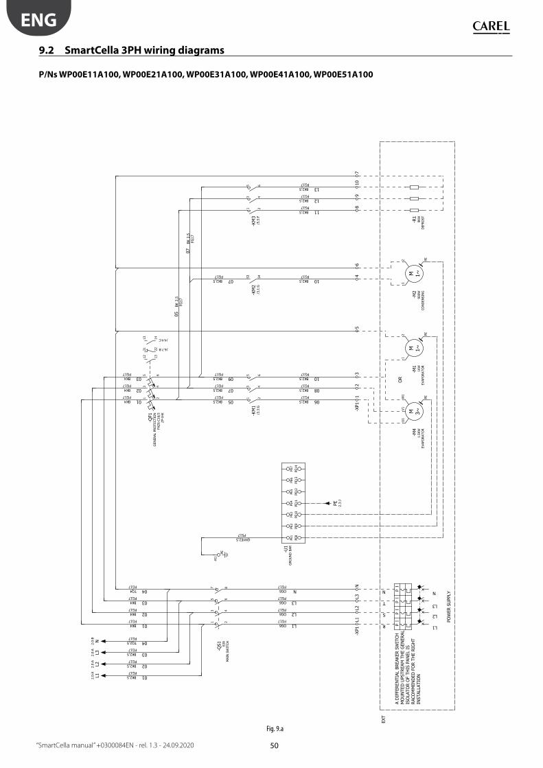
50
Fig. 9.a
ENG
“SmartCella manual” +0300084EN - rel. 1.3 - 24.09.2020
9.2 SmartCella 3PH wiring diagrams
P/Ns WP00E11A100, WP00E21A100, WP00E31A100, WP00E41A100, WP00E51A100

51
Fig. 9.b
ENG
“SmartCella manual” +0300084EN - rel. 1.3 - 24.09.2020
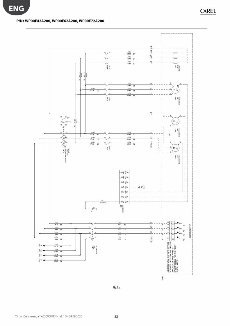
52
Fig. 9.c
ENG
“SmartCella manual” +0300084EN - rel. 1.3 - 24.09.2020
P/Ns WP00E42A200, WP00E62A200, WP00E72A200

53
Fig. 9.d
ENG
“SmartCella manual” +0300084EN - rel. 1.3 - 24.09.2020
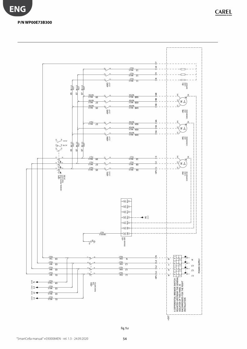
54
Fig. 9.e
ENG
“SmartCella manual” +0300084EN - rel. 1.3 - 24.09.2020
P/N WP00E73B300

55
Fig. 9.f
ENG
“SmartCella manual” +0300084EN - rel. 1.3 - 24.09.2020
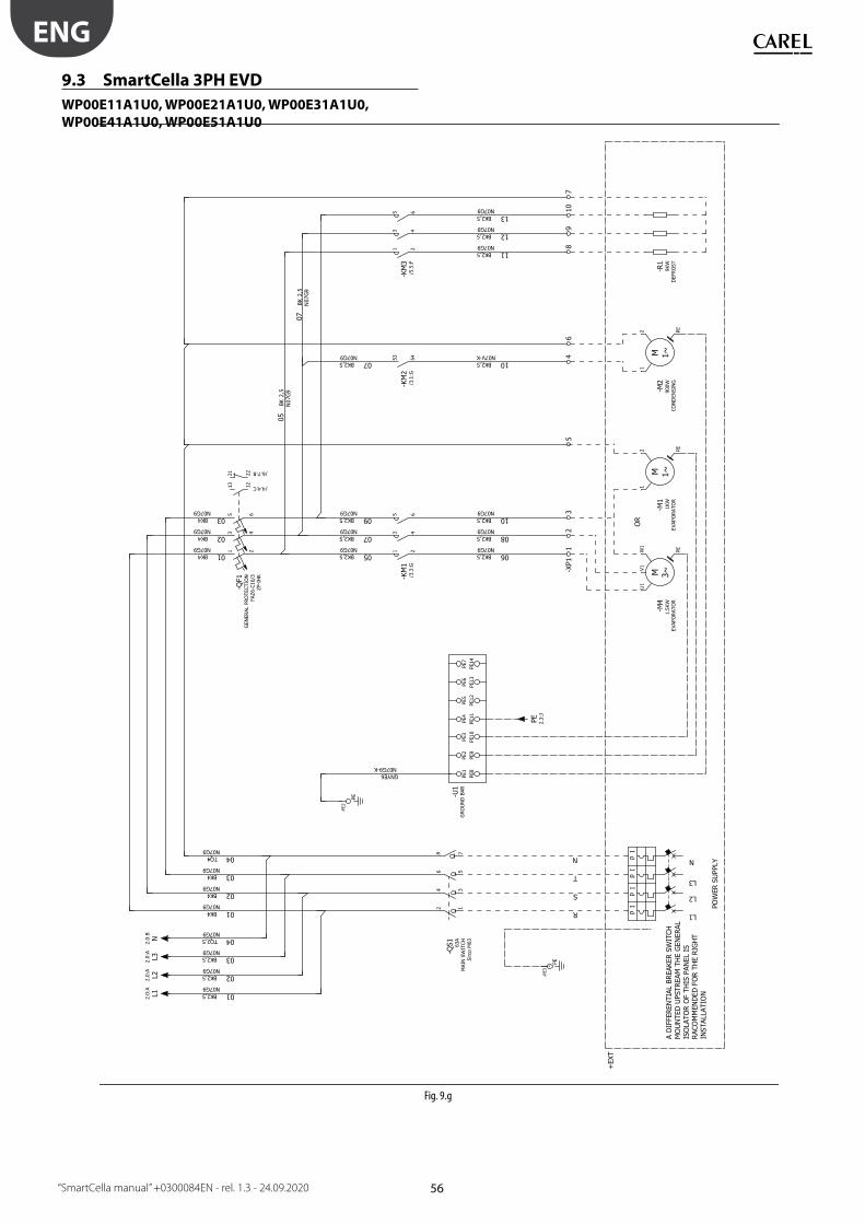
56
Fig. 9.g
ENG
“SmartCella manual” +0300084EN - rel. 1.3 - 24.09.2020
9.3 SmartCella 3PH EVD
WP00E11A1U0, WP00E21A1U0, WP00E31A1U0,
WP00E41A1U0, WP00E51A1U0

57
Fig. 9.h
ENG
“SmartCella manual” +0300084EN - rel. 1.3 - 24.09.2020

58
WP00E42A2U0, WP00E62A2U0, WP00E72A2U0
Fig. 9.i
ENG
“SmartCella manual” +0300084EN - rel. 1.3 - 24.09.2020
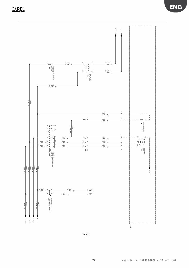
59
Fig. 9.j
ENG
“SmartCella manual” +0300084EN - rel. 1.3 - 24.09.2020
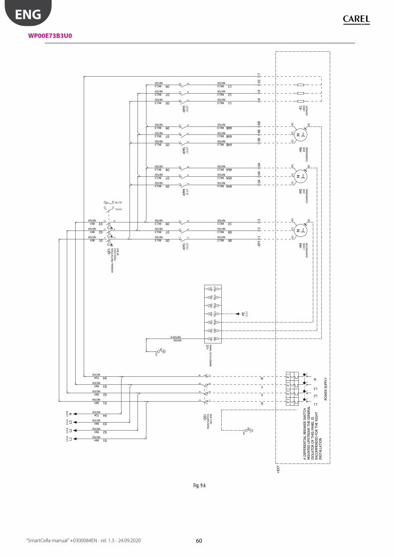
60
WP00E73B3U0
Fig. 9.k
ENG
“SmartCella manual” +0300084EN - rel. 1.3 - 24.09.2020

61
Fig. 9.l
ENG
“SmartCella manual” +0300084EN - rel. 1.3 - 24.09.2020
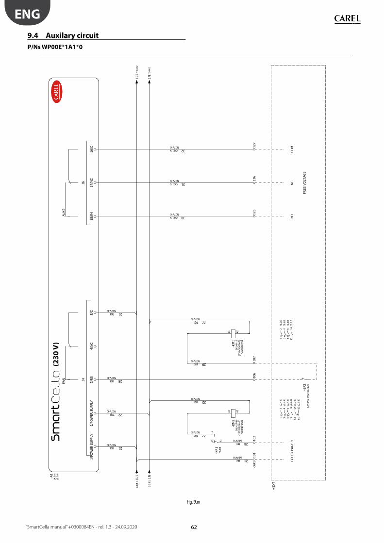
62
Fig. 9.m
(23
0 V
)
ENG
“SmartCella manual” +0300084EN - rel. 1.3 - 24.09.2020
9.4 Auxilary circuit
P/Ns WP00E*1A1*0

63
(23
0 V
)
Fig. 9.n
ENG
“SmartCella manual” +0300084EN - rel. 1.3 - 24.09.2020

64
Fig. 9.o
(23
0 V
)
ENG
“SmartCella manual” +0300084EN - rel. 1.3 - 24.09.2020
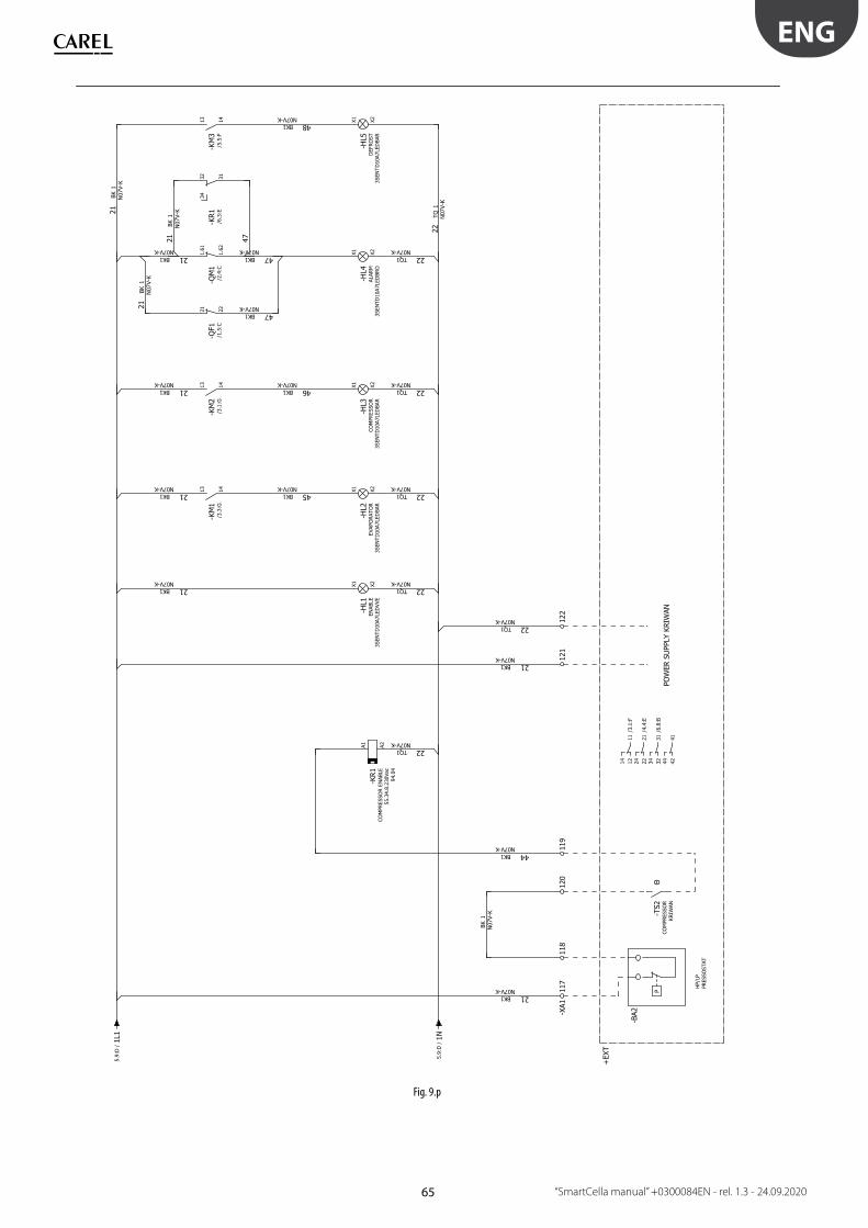
65
Fig. 9.p
ENG
“SmartCella manual” +0300084EN - rel. 1.3 - 24.09.2020

66
Fig. 9.q
ENG
“SmartCella manual” +0300084EN - rel. 1.3 - 24.09.2020
P/Ns WP00E*2A2*0

67
Fig. 9.r
ENG
“SmartCella manual” +0300084EN - rel. 1.3 - 24.09.2020

68
Fig. 9.s
ENG
“SmartCella manual” +0300084EN - rel. 1.3 - 24.09.2020

69
Fig. 9.t
ENG
“SmartCella manual” +0300084EN - rel. 1.3 - 24.09.2020

70
Fig. 9.u
ENG
“SmartCella manual” +0300084EN - rel. 1.3 - 24.09.2020
P/Ns WP00E73B3*0
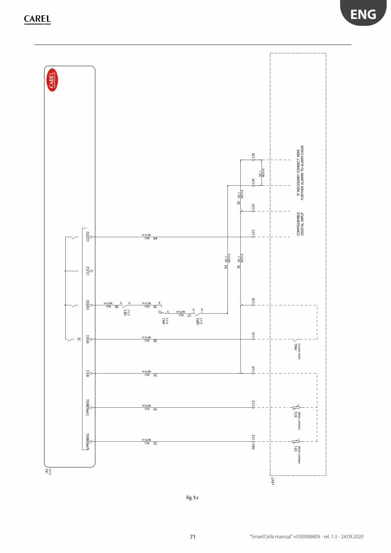
71
Fig. 9.v
ENG
“SmartCella manual” +0300084EN - rel. 1.3 - 24.09.2020

72
Fig. 9.w
ENG
“SmartCella manual” +0300084EN - rel. 1.3 - 24.09.2020

73
Fig. 9.x
ENG
“SmartCella manual” +0300084EN - rel. 1.3 - 24.09.2020
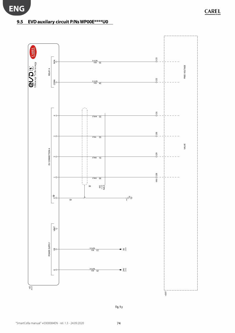
74
Fig. 9.y
ENG
“SmartCella manual” +0300084EN - rel. 1.3 - 24.09.2020
9.5 EVD auxilary circuit P/Ns WP00E****U0
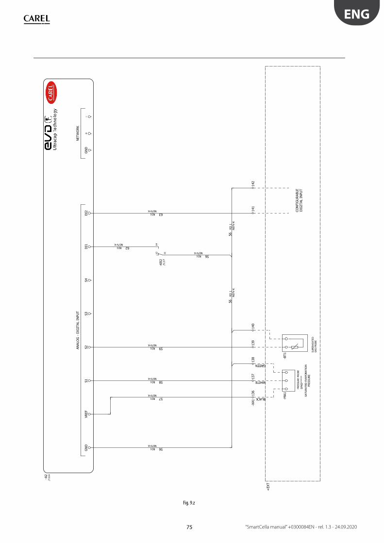
75
Fig. 9.z
ENG
“SmartCella manual” +0300084EN - rel. 1.3 - 24.09.2020
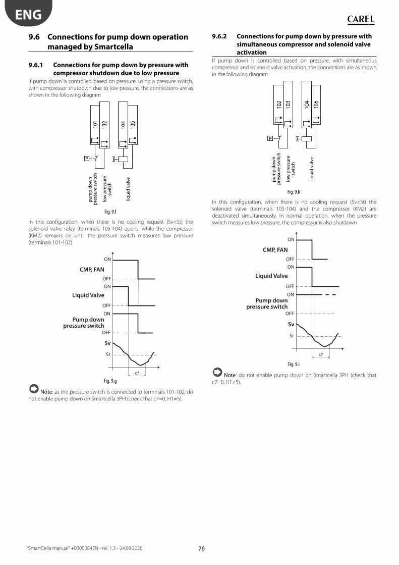
76
ENG
“SmartCella manual” +0300084EN - rel. 1.3 - 24.09.2020
9.6 Connections for pump down operation
managed by Smartcella
9.6.1 Connections for pump down by pressure with
compressor shutdown due to low pressureIf pump down is controlled based on pressure, using a pressure switch,
with compressor shutdown due to low pressure, the connections are as
shown in the following diagram
liqu
id v
alv
e
low
pre
ssu
resw
itch
pu
mp
do
wn
p
ress
ure
sw
itch
Fig. 9.f
In this confi guration, when there is no cooling request (Sv<St) the
solenoid valve relay (terminals 105-104) opens, while the compressor
(KM2) remains on until the pressure switch measures low pressure
(terminals 101-102)
ON
OFF
ON
OFF
CMP, FAN
Liquid Valve
c7
Pump downpressure switch
St
ON
OFF
Sv
Fig. 9.g
Note: as the pressure switch is connected to terminals 101-102, do
not enable pump down on Smartcella 3PH (check that c7=0, H1≠5).
9.6.2 Connections for pump down by pressure with
simultaneous compressor and solenoid valve
activationIf pump down is controlled based on pressure, with simultaneous
compressor and solenoid valve activation, the connections are as shown
in the following diagram
liqu
id v
alv
e
low
pre
ssu
resw
itch
pu
mp
do
wn
p
ress
ure
sw
itch
Fig. 9.h
In this confi guration, when there is no cooling request (Sv<St) the
solenoid valve (terminals 105-104) and the compressor (KM2) are
deactivated simultaneously. In normal operation, when the pressure
switch measures low pressure, the compressor is also shutdown
ON
OFF
ON
OFF
CMP, FAN
Liquid Valve
c7
Pump downpressure switch
St
ON
OFF
Sv
Fig. 9.i
Note: do not enable pump down on Smartcella 3PH (check that
c7=0, H1≠5).
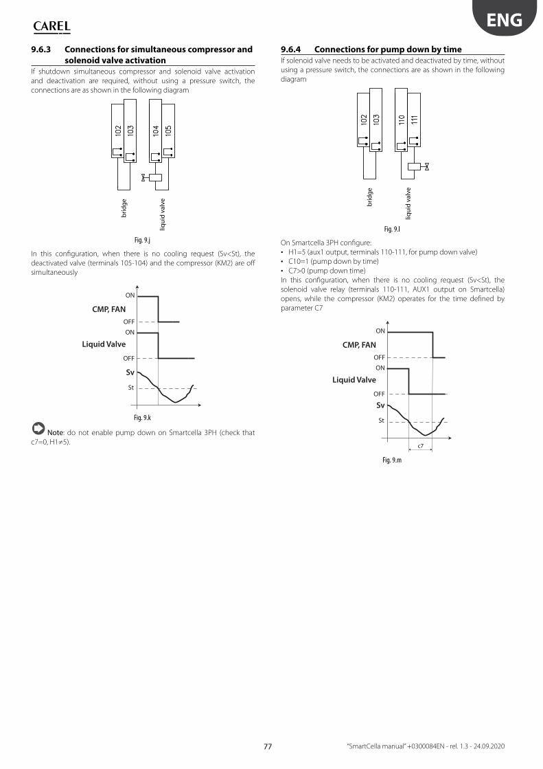
77
ENG
“SmartCella manual” +0300084EN - rel. 1.3 - 24.09.2020
9.6.3 Connections for simultaneous compressor and
solenoid valve activationIf shutdown simultaneous compressor and solenoid valve activation
and deactivation are required, without using a pressure switch, the
connections are as shown in the following diagram
liqu
id v
alv
e
bri
dg
e
Fig. 9.j
In this confi guration, when there is no cooling request (Sv<St), the
deactivated valve (terminals 105-104) and the compressor (KM2) are off
simultaneously
ON
OFF
ON
OFF
CMP, FAN
Liquid Valve
St
Sv
Fig. 9.k
Note: do not enable pump down on Smartcella 3PH (check that
c7=0, H1≠5).
9.6.4 Connections for pump down by timeIf solenoid valve needs to be activated and deactivated by time, without
using a pressure switch, the connections are as shown in the following
diagram
liqu
id v
alv
e
bri
dg
e
Fig. 9.l
On Smartcella 3PH confi gure:
• H1=5 (aux1 output, terminals 110-111, for pump down valve)
• C10=1 (pump down by time)
• C7>0 (pump down time)
In this confi guration, when there is no cooling request (Sv<St), the
solenoid valve relay (terminals 110-111, AUX1 output on Smartcella)
opens, while the compressor (KM2) operates for the time defi ned by
parameter C7
ON
OFF
ON
OFF
CMP, FAN
Liquid Valve
c7
St
Sv
Fig. 9.m

78
ENG
“SmartCella manual” +0300084EN - rel. 1.3 - 24.09.2020
10. APPENDIX 1: VPM (VISUAL PARAMETER MANAGER)
10.1 Installation Go to http://ksa.carel.com and select the following path:
Software & Support Confi guration & Updating Softwares Parametric
controller software
then select Visual Parametric Manager.
A dialogue box is opened, with the possibility to download 3 fi les:
1. VPM_CD.zip: for burning a CD/DVD;
2. Upgrade setup;
3. Full setup: this is the complete program.
For fi rst installations, select Full setup, for upgrades select Upgrade setup.
The program is installed automatically by running setup.exe.
Important: if deciding to run the complete installation (Full setup),
uninstall any previous versions of VPM.
10.2 Opening the programProgramming can be performed using the key (IROPZKEYA0), connected
to the computer via the converter (IROPZPRG00).
When opening the VPM program, choose the device to be confi gured:
ir33. The Home page is displayed, with the options to create a new
project or open an existing project. Choose new project and enter the
password, which can be set as desired by the user the fi rst time. Select
the OEM profi le.
Fig. 10.a
Then:
1. upload the control parameters to the key, as described in chapter 2;
2. read the parameters from the key.
10.3 Computer - key connectionTo connect the computer to the key:
• Select the list of parameters on the E2PROM key as the source;
Fig. 10.b
• Select the key connection port using the guided procedure (Wizard);
Fig. 10.c
• Connect the programming key to the converter..
10.4 ProgrammingGo to the “Confi gure device” page and select “Read”
Fig. 10.d
Fig. 10.e
A progress bar is displayed. When reading the data, the LEDs on the
converter fl ash, and at the bottom right the message “ONLINE” is
displayed.
Fig. 10.f

79
ENG
“SmartCella manual” +0300084EN - rel. 1.3 - 24.09.2020
At the end, the list of parameters read is displayed.
Fig. 10.g
10.5 Modify a parameterMove the cursor to the “Written” column and double click the cell: enter
the new value.
Fig. 10.h
10.6 Add a set of parametersUp to 6 set of parameters can be added to Set0: Set0, Set1, Set2, Set3,
Set4, Set5, Set6. To do this:
• move the cursor to Set0 and click the right button; choose “Add set” for
each additional set;
Fig. 10.i
• Set1 is displayed
Fig. 10.j
Note:
• on the controller, Set0, Set1, …, Set6 are named bn0 to bn6 respectively;
• Set0 is the default set on the controller, i.e. the default confi guration.
When loading a diff erent set (Set1...Set6), Set0 is overwritten with the
new set and is consequently erased.
10.7 Write parametersTo write the parameters to the controller:
• Write the parameters to the key by selecting “Write”;
Fig. 10.k
• Transfer the parameters from the key to the controller using the
“Download” function, as described in the chapter on “Installation”.
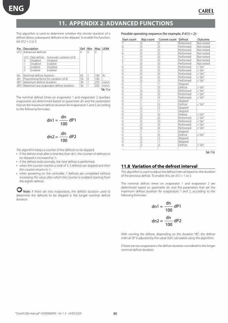
80
ENG
“SmartCella manual” +0300084EN - rel. 1.3 - 24.09.2020
11. APPENDIX 2: ADVANCED FUNCTIONS
This algorithm is used to determine whether the shorter duration of a
defrost allows subsequent defrosts to be skipped. To enable the function,
set d12 = 2 or 3.
Par. Description Def Min Max UOMd12 Advanced defrosts
d12 Skip defrost Automatic variation of dI0 Disabled Disabled1 Disabled Enabled2 Enabled Disabled3 Enabled Enabled
0 0 3 -
dn Nominal defrost duration 65 1 100 %dH Proportional factor for variation of dI 50 0 100 -dP1 Maximum defrost duration 30 1 250 min/sdP2 Maximum aux evaporator defrost duration 30 1 250 min/s
Tab. 11.a
The nominal defrost times on evaporator 1 and evaporator 2 (auxiliary
evaporator) are determined based on parameter dn and the parameters
that set the maximum defrost duration for evaporators 1 and 2, according
to the following formulae:
dn1 = dn
100dP1
dn2 = dn
100dP2
The algorithm keeps a counter of the defrosts to be skipped:
• if the defrost ends after a time less than dn1, the counter of defrosts to
be skipped is increased by 1;
• if the defrost ends normally, the next defrost is performed;
• when the counter reaches a total of 3, 3 defrosts are skipped and then
the counter returns to 1;
• when powering on the controller, 7 defrosts are completed without
increasing the value, after which the counter is enabled (starting from
the eighth defrost).
Note: if there are two evaporators, the defrost duration used to
determine the defrosts to be skipped is the longer nominal defrost
duration.
Possible operating sequence (for example, if d12 = 2):
Start count Skip count Current count Defrost Outcome
7 0 0 Performed Not tested6 0 0 Performed Not tested5 0 0 Performed Not tested4 0 0 Performed Not tested3 0 0 Performed Not tested2 0 0 Performed Not tested1 0 0 Performed Not tested0 0 0 Performed > “dn”0 0 0 Performed > “dn”0 0 0 Performed > “dn”0 0 0 Performed > “dn”0 0 0 Performed < “dn”0 1 1 Skipped0 1 0 Defrost > “dn”0 0 0 Performed > “dn”0 0 0 Performed > “dn”0 0 0 Performed < “dn”0 1 1 Skipped0 1 0 Defrost < “dn”0 2 2 Skipped0 2 1 Skipped0 2 0 Defrost > “dn”0 0 0 Performed > “dn”0 0 0 Performed > “dn”0 0 0 Performed > “dn”0 0 0 Performed < “dn”0 1 1 Skipped0 1 0 Defrost < “dn”0 2 2 Skipped0 2 1 Skipped0 2 0 Defrost < “dn”…
Tab. 11.b
11.8 Variation of the defrost intervalThis algorithm is used to adjust the defrost interval based on the duration
of the previous defrost. To enable this, set d12 = 1 or 3.
The nominal defrost times on evaporator 1 and evaporator 2 are
determined based on parameter dn and the parameters that set the
maximum defrost duration for evaporators 1 and 2, according to the
following formulae:
dn1 = dn
100dP1
dn2 = dn
100dP2
With running the defrost, depending on the duration “dE”, the defrost
interval “dI” is adjusted by the value “ΔdI”, calculated using the algorithm.
If there are two evaporators, the defrost duration considered is the longer
nominal defrost duration.

81
ENG
“SmartCella manual” +0300084EN - rel. 1.3 - 24.09.2020
11.9 Defrost with 2 evaporatorsUp to 3 defrost probes and up to 2 evaporator outputs can be confi gured.
The controller recognises the basic confi guration shown in the table
below (probe 1 is the control probe and cannot be confi gured).
DEFROST PROBE AND EVAPORATOR OUTPUT CONFIGURATION
Case Defrost probes Evaporator
outputs
Notes
1 Probe 2 Evap. 1 Probe 2 acts on evap. 12 Probe 2 Evap. 1
and 2
Probe 2 acts on evap. 1 and 2
3 Probe 2 Evap. 1 Probes 2 and 3 act on evap. 1 (start
and end defrost refer to the probe
with the lower value)
Probe 3
4 Probe 2 Evap. 1 Probes 2, 3, 4 act on evap. 1 (start and
end defrost refer to the probe with the
lower value)
Probe 3Probe 4
5 Probe 2 Evap. 1 Probe 1 acts on evap. 1Probe 3 Evap. 2 Probe 2 acts on evap. 2
6 Probe 2Probe 4 Evap. 1 Probe 2 and 4 act on evap. 1 (end
defrost if all probes > end defrost
threshold.)Probe 3Probe 4 Evap. 2 Probe 3 and 4 act on evap. 2 (end
defrost if all probes > end defrost
threshold.)
Tab. 11.c
Case 6 refers to the confi guration with 1 probe on each evaporator and
1 probe in common.
CASE 6: probe 2, probe 4 on evaporator 1, probe 3, probe 4 on
evaporator 2.
C
L
CMP
T V1
T V2
E2
E1
S2
S3
S4
SmartCella
S
F
Fig. 11.a
KeyE1/2 Evaporator 1/2 S2/3/4 Defrost probe 2, 3, 4C Condenser CMP CompressorV1/2 Electronic expansion valve 1/2 F Filter-drierL Liquid receiver S Liquid gaugeV1/2 Thermostatic expansion valve 1/2
The following situations may occur if the outputs are not confi gured or
there are probe alarms.
DEFROST BY TEMPERATURE
Defrost probe / evap.
output confi g.
Situation Eff ect
Probe 2 defrost output 1 No probe Defrost ends by timeout
(dP1)Probe available, probe
error
Defrost ends by timeout
(dP1)Probe 3
defrost output 2
No probeAUX1 confi gured Defrost ends by timeout
(dP1)AUX2 confi gured Defrost ends by timeout
(dP2)AUX1 and AUX2 not
confi gured
Not performed
Probe available, probe
error
Defrost ends by timeout
(dP2)Probe available and
AUX1 and AUX2 not
confi gured
Defrost performed on
defrost output
Probe 4 together with
probe 2 and probe
3defrost output 1 and
defrost output 2
No probe, not managed Cases 4, 6 not
recognisedProbe available, probe
error
Defrost ends by timeout
Tab. 11.d
DEFROST BY TIME
Defrost probe /
evap. output confi g.
Situation Eff ect
Defrost output 1 AUX1 confi gured Defrost ends by timeout (dP1)AUX2 confi gured Defrost ends by timeout (dP2)AUX1 and AUX2
not confi gured
Defrost not performed
Tab. 11.e
Note: AUX1 and AUX 2 confi gured as evaporator outputs are not
equivalent..
11.10 Second compressor with rotationSecond compressor output with two step control and rotation. The
role of main and secondary compressor are alternated whenever the
compressor stops, so that when next called to start (or stop), the output
not involved in the previous start (stop) will be activated (deactivated).
Par. Description Def Min Max UoMH1/H5 AUX/AUX2 output confi guration
0 = normally energised alarm
…
13 = second compressor step with rotation
1/3 0 13 -
Tab. 11.f
ON
OFFCP1
CP2
Sv
ON
OFF
St
St+rd
St+rd/2
t
t
tFig. 11.b

82
ENG
“SmartCella manual” +0300084EN - rel. 1.3 - 24.09.2020
CP1ON
OFF
rd/2 rd/2
CP2ON
OFF
D
D
Sv
StFig. 11.c
KeySv Virtual probe CP2 Compressor 2CP1 Compressor 1 rd Diff erentialt time St Set point
Examples of operation:
ON
OFFREQ2
CP1
CP2
REQ1
ON
OFF
ON
OFF
OFF
ONEXAMPLE 1
t
t
t
t Fig. 11.d
ON
OFFREQ2
CP1
CP2
REQ1
ON
OFF
ON
OFF
OFF
ONEXAMPLE 2
t
t
t
t
Fig. 11.e
ON
OFFREQ2
CP1
CP2
REQ1
ON
OFF
ON
OFF
OFF
ONEXAMPLE 3
t
t
t
t
Fig. 11.f
ON
OFFREQ2
CP1
CP2
REQ1
ON
OFF
ON
OFF
OFF
ONEXAMPLE 4
t
t
t
t Fig. 11.g
KeyREQ1 compressor 1 call CP1 compressor 1REQ2 compressor 2 call CP2 compressor 2t time


CAREL INDUSTRIES S.p.A.
Via dell’Industria, 11 - 35020 Brugine - Padova (Italy)
Tel. (+39) 049.9716611 - Fax (+39) 049.9716600
e-mail: [email protected] - www.carel.com
Agenzia / Agency:
“Sm
artC
ella
/Sm
artC
ella
3P
H” +
03
00
08
4EN
- r
el.
1.3
- 2
4.0
9.2
02
0
Related Documents