1 User Interface Guide

Welcome message from author
This document is posted to help you gain knowledge. Please leave a comment to let me know what you think about it! Share it to your friends and learn new things together.
Transcript

1
User Interface Guide

2
Contents Overview ......................................................................................................................................... 3
Tabmenu ......................................................................................................................................... 4
Design modes .............................................................................................................................. 4
Tool groups ................................................................................................................................. 5
Design function groups ............................................................................................................... 5
Main menu ...................................................................................................................................... 6
Toolbars .......................................................................................................................................... 7
Drawing area ................................................................................................................................... 9
Status bar ...................................................................................................................................... 11
Coordinate box .......................................................................................................................... 11
Layer button .............................................................................................................................. 11
Special point editors ................................................................................................................. 11
Object snap tools ...................................................................................................................... 11
Command line ........................................................................................................................... 11
Filter .............................................................................................................................................. 13
Tool palettes ................................................................................................................................. 14
Dialogs ........................................................................................................................................... 16
Chain button ............................................................................................................................. 16
Numeric edit boxes ................................................................................................................... 16
List boxes ................................................................................................................................... 16
Key bindings .................................................................................................................................. 17
3
Overview

4
Tabmenu
This toolbar contains the main functionalities.
The order of the tabs follows the suggested workflow of design.
Each tab has different layer mode. By default, the status of the layers (Hidden, Protected, Active) is different for each tab according to the function of the particular tab, so that you cannot, for example, delete or alter a structural element accidentally while working with loads. The status of any layer can also be adjusted manually, however (Status bar/Current layer).
Design modes
The buttons on the right side of the tabmenu represent various design modes. When in a particular design mode, the set of tabs in the tabmenu might change to reflect the functionalities available to that particular design mode.
Documentation - In this mode, multi-page documentation of your project can be defined manually or by applying templates. New templates can also be created. Documentation can contain figures of structure, loads and results, chapters, texts, tables, images and title blocks (headers and footers).
Exit current mode - Pressing this button, you can return to the previous design mode.

5
Tool groups
Tools are organized into groups on the tabmenu. To spare space on the screen, most of them can be compacted into a single button, by clicking on the grey triangle at the lower left corner of the group. By clicking the grey triangle again the group can be reexpanded.
Expanded group - an expanded tool group behaves just like and ordinary group, having a separate icon for each item of the group.
Compacted group - a collapsed group is represented by a single icon on the tabmenu. Clicking the icon, it works like a simple push button. Hovering the mouse over the bottom right corner of the button (over the black triangle), a dropmenu appears, where you can select another tool from the group.
Design function groups
While designing reinforced concrete, steel or timber structures, a design function group is displayed on the tabmenu. It allows the user to select a particular structure or feature to design, as well as providing access to functionalities available to that structure only. You can switch function by clicking the leftmost icon of the group and select an item from the dropdown menu. Please note that, unlike that of a tool group, the icon of a design function group does not behave like a push button, it merely shows the current design mode.

6
Main menu
The Main menu contains file operations, drawing and editing commands, assistance tools, settings, views, window-system and user-guides (Help).
Each menu item (a command along with the corresponding icon) can be placed as a button on one of the toolbars, that can be placed around the Drawing area.
Some commands can be executed by hotkeys. The hotkey (or combination) for a particular command can be found on the right side of the dropdown menu along with the associated item.

7
Toolbars
The command icons of Main menu can be grouped into toolbars and placed around the Drawing area. By default, only the Standard and View toolbars are shown, the others remain hidden.
You can drag a toolbar and move it around by clicking the left mouse button over the left edge of the toolbar and holding the button pressed. You can stick the toolbar to any of the four edges of the drawing area. If you right-click anywhere on the menu or on one of the additional toolbars, you can choose which toolbars are to be shown or hidden from the popup menu.
By selecting the "Customize..." menu item, you may add or remove icons from the current toolbar (which was clicked upon).

8

9
Drawing area
The thin arrows show the axes of the Global (or World) Coordinate System (WCS). The position of the origin and directions are fixed. The green and red infinite lines show the x' and y' axes of the user coordinate system (UCS) respectively. Its origin and directions can be modified at "View/UCS".
If the origin of the UCS is out of the current view, the two thick arrows remains in view at the bottom of the drawing area giving the user a hint about the directions of the UCS. The location of the two arrows on the drawing area depends on your setting on "Settings/All/Window/Coordinate systems".

10
A list of currently available windows are shown at the bottom of the drawing area. In this case you can choose a window simply by clicking on its name. You may change the window's name of a window by right-clicking on its tab.
Default mouse button actions available in the drawing area: Right button "Edit" menu
Wheel up Zoom In
Wheel down Zoom Out
Middle button Animate pan
Ctrl + Middle button Animate rotate around the center of the model cube
Alt + Middle button Animate rotate around the user defined point
Middle button double click Zoom margin
There are quite a few ways to select objects: "Right to Left sweep" box selection Selects everything that the selection box intersects or
covers.
"Left to Right sweep" box selection Selects everything that is completely inside the box.
Right button Selects the object that the cursor is hovering over.
Shift + Right button Selects the object that the cursor is hovering over plus all the other objects of the same type.
Ctrl + selection When holding "Ctrl" key pressed while selecting the first object by any of the methods above, the program lets you continue selection until "Enter" is pressed.
Ctrl + A Selects all the objects the current command is applicable to.
Quick modifications are implemented for all elements, depending on where the cursor is standing: Click LB
(default) Click + hold
LB CTRL + hold
LB
Line's end point Node on surface edge
Stretch Stretch
Drag a copy
Along point along line
Curve Move Drag a copy
Any point inside surface Move Move Drag a copy Any point on screen, where there is nothing
Box selection
By right mouse clicking user can select another command in the Modify menu, whick is also available by right mouse clicking.

11
Status bar
Coordinate box
Shows the exact coordinates of the crosshair cursor. If you click on the box, while you are in any drawing and definition tools, you can define an exact coordinate of the point. The coordinate can be valid in WCS or UCS
By clicking this button, you may change the orthogonal coordinate system to parametric coordinate system.
Layer button
By clicking on this button you may access the layer manager of the application, where you can set the status and properties of all the layers .
Special point editors
This option will provide reference line and point by using existing line and point during drawing and editing.
Object snap tools
Here you can set the snapping distance and turn object snaps on and off.
Command line
Here you can directly communicate with the program (eg.: typing in coordinate values). This field displays additional messages to show the steps of the current command.

12
In the command line you can define coordinates in several way: 10 30 20 or 10,30,20
Using absolute coordinates in Descartes coordinate system: X=10, Y=30, Z=20. If only 2 coordinates are defined then Z=0.
P 45 5 10 Using polar coordinates: point is positioned with an angle of 45 degrees and 5 units from the X-axis and 10 units from the XY plane.
R 2.5 3.5 4.5 or @2.5,3.5,4.5
Using relative coordinates: point is positioned X=2.5, Y=3.5, Z=4.5 units from the last entered point. If only 2 coordinates are defined then Z=0.
The coordinates are always valid in UCS. Add decimal point by "." (dot instead of comma).

13
Filter
The new feature �Filter� is a pop-up window in the workspace, which helps to select the requested objects easily for all kind of editing and modifying functions. When clicking on it, the following appears:
With the cursor pointing on �Point support group� �+�,�-� and �&� buttons appear, enabling the user to add or remove different elements. If you want to select most, but not all of the point support groups, you should click �+�, and then �Continue� for cancelling the few individual supports not needed for the selection. The �&� button works as an �AND� boolean operator: If you want to select the columns on the second storey, you have to click �+� at column and then �&� at storey 2. After closing the Filter palette, it can be switched on again by a right click on any toolbar, or on the main menu zone. Another way is available through Settings>All�>Environment>General>View where filter palette can switched on and off:

14
Tool palettes
In most cases a command has its own "Tool palette", containing all the neccessary definitions and settings related to that particular command.
The parts of a tool palette:
Toolbar
This toolbar is used to change editing mode. Main editing modes are:
Define Creates new objects with current settings (Default settings).
Properties Ask and/or changes the properties of selected object/s.
"Default settings" button
If this button is enabled, then you can set all default parameters for the given object type. Otherwise it only shows the symbol of the function.

15
Object parameters
Here you can set the frequently changed parameters of the object while defining it.

16
Dialogs
Chain button
If there is a "Chain" button next to an edit box and is pressed, any changes made to the
related edit box will be transferred to the next edit box automatically.
At the second example, if you set t1's value to '0.20000' then t2 and t3 will also be set to '0.20000'.
Numeric edit boxes
If you press "c" button on the keyboard while a numeric field has the focus, then the Windows Calculator pops up. It is automatically filled in with the content of the edit box. When you close the Calculator, the value calculated or typed in would be written into the numeric field. It can be used with both views of the Calculator (Normal and Scientific).
List boxes
In some cases if you double-click on a list box item, then - apart from selecting the given item - the program performs an additional function.
E.g.: when selecting an item in "Select result" dialog with a double-click, the program also calls the "Display and exit" command of the dialog.
17
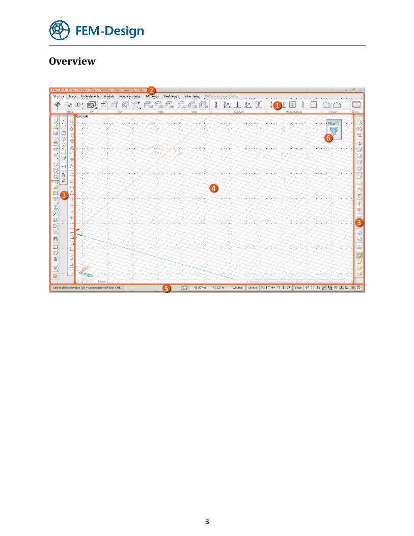
Key bindings
The following buttons have special functionalities during editing:
... Temporarily activate object snap functions.
Defines point on a line or edge by giving distance from the closest end point.
Inserts a point relative from the position of the crosshair.
Moves UCS to cursor position.
+ Moves UCS back to WCS (restores its original state).
Cancels pending command.
Opens the properties dialog ("Default settings") of the current command.
Confirms data input / repeats last command / finishes multi-selection.
Restarts the steps of the current command.
Goes back to previous step in a multi-step command.
Besides these, most of the commands can be accessed by hotkeys (see Main menu).
Related Documents