1910011427 REV2.1.0 TL-WR843N User Guide 300Mbps Wireless AP/Client Router

Welcome message from author
This document is posted to help you gain knowledge. Please leave a comment to let me know what you think about it! Share it to your friends and learn new things together.
Transcript

1910011427 REV2.1.0
TL-WR843NUser Guide
300Mbps Wireless AP/Client Router
ContentsAbout This Guide ...............................................................................................1
Chapter 1. Get to Know About Your Router . . . . . . . . . . . . . . . . . . . . . . . . . 2
1. 1. Product Overview . . . . . . . . . . . . . . . . . . . . . . . . . . . . . . . . . . . . . . . . . . . . . . . . . . . . . . . . . . 31. 2. Appearance . . . . . . . . . . . . . . . . . . . . . . . . . . . . . . . . . . . . . . . . . . . . . . . . . . . . . . . . . . . . . . . . 3
Chapter 2. Connect the Hardware. . . . . . . . . . . . . . . . . . . . . . . . . . . . . . . . . . 5
2. 1. Position Your Router . . . . . . . . . . . . . . . . . . . . . . . . . . . . . . . . . . . . . . . . . . . . . . . . . . . . . . . . 62. 2. Connect Your Router . . . . . . . . . . . . . . . . . . . . . . . . . . . . . . . . . . . . . . . . . . . . . . . . . . . . . . . 6
Chapter 3. Set Up Internet Connection Via Quick Setup Wizard . . . . . . 9
3. 1. Log into the Router. . . . . . . . . . . . . . . . . . . . . . . . . . . . . . . . . . . . . . . . . . . . . . . . . . . . . . . . 103. 2. Configure the Router . . . . . . . . . . . . . . . . . . . . . . . . . . . . . . . . . . . . . . . . . . . . . . . . . . . . . . 10
Chapter 4. Configure the Router in WISP Client Router Mode . . . . . . . 16
4. 1. Status. . . . . . . . . . . . . . . . . . . . . . . . . . . . . . . . . . . . . . . . . . . . . . . . . . . . . . . . . . . . . . . . . . . . . 174. 2. WPS . . . . . . . . . . . . . . . . . . . . . . . . . . . . . . . . . . . . . . . . . . . . . . . . . . . . . . . . . . . . . . . . . . . . . . 184. 3. Working Mode . . . . . . . . . . . . . . . . . . . . . . . . . . . . . . . . . . . . . . . . . . . . . . . . . . . . . . . . . . . . 204. 4. Network . . . . . . . . . . . . . . . . . . . . . . . . . . . . . . . . . . . . . . . . . . . . . . . . . . . . . . . . . . . . . . . . . . 214. 5. Wireless. . . . . . . . . . . . . . . . . . . . . . . . . . . . . . . . . . . . . . . . . . . . . . . . . . . . . . . . . . . . . . . . . . . 294. 6. Guest Network . . . . . . . . . . . . . . . . . . . . . . . . . . . . . . . . . . . . . . . . . . . . . . . . . . . . . . . . . . . . 354. 7. DHCP . . . . . . . . . . . . . . . . . . . . . . . . . . . . . . . . . . . . . . . . . . . . . . . . . . . . . . . . . . . . . . . . . . . . . 374. 8. Forwarding . . . . . . . . . . . . . . . . . . . . . . . . . . . . . . . . . . . . . . . . . . . . . . . . . . . . . . . . . . . . . . . 394. 9. Security . . . . . . . . . . . . . . . . . . . . . . . . . . . . . . . . . . . . . . . . . . . . . . . . . . . . . . . . . . . . . . . . . . . 434. 10. Parental Controls . . . . . . . . . . . . . . . . . . . . . . . . . . . . . . . . . . . . . . . . . . . . . . . . . . . . . . . . . . 484. 11. Access Control . . . . . . . . . . . . . . . . . . . . . . . . . . . . . . . . . . . . . . . . . . . . . . . . . . . . . . . . . . . . 504. 12. Advanced Routing . . . . . . . . . . . . . . . . . . . . . . . . . . . . . . . . . . . . . . . . . . . . . . . . . . . . . . . . 524. 13. Bandwidth Control . . . . . . . . . . . . . . . . . . . . . . . . . . . . . . . . . . . . . . . . . . . . . . . . . . . . . . . . 544. 14. IP&MAC Binding. . . . . . . . . . . . . . . . . . . . . . . . . . . . . . . . . . . . . . . . . . . . . . . . . . . . . . . . . . . 554. 15. Dynamic DNS . . . . . . . . . . . . . . . . . . . . . . . . . . . . . . . . . . . . . . . . . . . . . . . . . . . . . . . . . . . . . 574. 16. System Tools . . . . . . . . . . . . . . . . . . . . . . . . . . . . . . . . . . . . . . . . . . . . . . . . . . . . . . . . . . . . . . 604. 17. Logout. . . . . . . . . . . . . . . . . . . . . . . . . . . . . . . . . . . . . . . . . . . . . . . . . . . . . . . . . . . . . . . . . . . . 68
Chapter 5. Configure the Router in Standard Wireless Router Mode. 69
5. 1. Status. . . . . . . . . . . . . . . . . . . . . . . . . . . . . . . . . . . . . . . . . . . . . . . . . . . . . . . . . . . . . . . . . . . . . 705. 2. WPS . . . . . . . . . . . . . . . . . . . . . . . . . . . . . . . . . . . . . . . . . . . . . . . . . . . . . . . . . . . . . . . . . . . . . . 715. 3. Working Mode . . . . . . . . . . . . . . . . . . . . . . . . . . . . . . . . . . . . . . . . . . . . . . . . . . . . . . . . . . . . 735. 4. Network . . . . . . . . . . . . . . . . . . . . . . . . . . . . . . . . . . . . . . . . . . . . . . . . . . . . . . . . . . . . . . . . . . 735. 5. Wireless. . . . . . . . . . . . . . . . . . . . . . . . . . . . . . . . . . . . . . . . . . . . . . . . . . . . . . . . . . . . . . . . . . . 825. 6. Guest Network . . . . . . . . . . . . . . . . . . . . . . . . . . . . . . . . . . . . . . . . . . . . . . . . . . . . . . . . . . . . 885. 7. DHCP . . . . . . . . . . . . . . . . . . . . . . . . . . . . . . . . . . . . . . . . . . . . . . . . . . . . . . . . . . . . . . . . . . . . . 905. 8. Forwarding . . . . . . . . . . . . . . . . . . . . . . . . . . . . . . . . . . . . . . . . . . . . . . . . . . . . . . . . . . . . . . . 925. 9. Security . . . . . . . . . . . . . . . . . . . . . . . . . . . . . . . . . . . . . . . . . . . . . . . . . . . . . . . . . . . . . . . . . . . 965. 10. Parental Controls . . . . . . . . . . . . . . . . . . . . . . . . . . . . . . . . . . . . . . . . . . . . . . . . . . . . . . . . . 1015. 11. Access Control . . . . . . . . . . . . . . . . . . . . . . . . . . . . . . . . . . . . . . . . . . . . . . . . . . . . . . . . . . . 1035. 12. Advanced Routing . . . . . . . . . . . . . . . . . . . . . . . . . . . . . . . . . . . . . . . . . . . . . . . . . . . . . . . 1055. 13. Bandwidth Control . . . . . . . . . . . . . . . . . . . . . . . . . . . . . . . . . . . . . . . . . . . . . . . . . . . . . . . 1075. 14. IP&MAC Binding. . . . . . . . . . . . . . . . . . . . . . . . . . . . . . . . . . . . . . . . . . . . . . . . . . . . . . . . . . 1085. 15. Dynamic DNS . . . . . . . . . . . . . . . . . . . . . . . . . . . . . . . . . . . . . . . . . . . . . . . . . . . . . . . . . . . . 1105. 16. IPv6 Support . . . . . . . . . . . . . . . . . . . . . . . . . . . . . . . . . . . . . . . . . . . . . . . . . . . . . . . . . . . . . 1135. 17. System Tools . . . . . . . . . . . . . . . . . . . . . . . . . . . . . . . . . . . . . . . . . . . . . . . . . . . . . . . . . . . . . 1195. 18. Logout. . . . . . . . . . . . . . . . . . . . . . . . . . . . . . . . . . . . . . . . . . . . . . . . . . . . . . . . . . . . . . . . . . . 127
Chapter 6. Configure the Router in Repeater Mode . . . . . . . . . . . . . . . 129
6. 1. Status. . . . . . . . . . . . . . . . . . . . . . . . . . . . . . . . . . . . . . . . . . . . . . . . . . . . . . . . . . . . . . . . . . . . 1306. 2. Working Mode . . . . . . . . . . . . . . . . . . . . . . . . . . . . . . . . . . . . . . . . . . . . . . . . . . . . . . . . . . . 1316. 3. Network . . . . . . . . . . . . . . . . . . . . . . . . . . . . . . . . . . . . . . . . . . . . . . . . . . . . . . . . . . . . . . . . . 1316. 4. Wireless. . . . . . . . . . . . . . . . . . . . . . . . . . . . . . . . . . . . . . . . . . . . . . . . . . . . . . . . . . . . . . . . . . 1326. 5. DHCP . . . . . . . . . . . . . . . . . . . . . . . . . . . . . . . . . . . . . . . . . . . . . . . . . . . . . . . . . . . . . . . . . . . . 1396. 6. System Tools . . . . . . . . . . . . . . . . . . . . . . . . . . . . . . . . . . . . . . . . . . . . . . . . . . . . . . . . . . . . . 1416. 7. Logout. . . . . . . . . . . . . . . . . . . . . . . . . . . . . . . . . . . . . . . . . . . . . . . . . . . . . . . . . . . . . . . . . . . 148
FAQ .................................................................................................................. 149
1
About This GuideThis guide is a complementation of Quick Installation Guide. The Quick Installation Guide instructs you on quick Internet setup, and this guide provides details of each function and shows you the way to configure these functions appropriate to your needs.
When using this guide, please notice that features of the router may vary slightly depending on the model and software version you have, and on your location, language, and Internet service provider. All screenshots, images, parameters and descriptions documented in this guide are used for demonstration only.
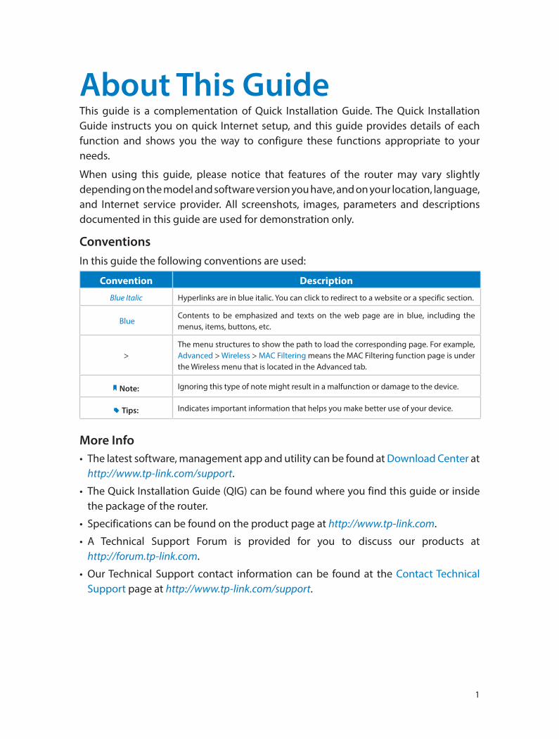
ConventionsIn this guide the following conventions are used:
Convention Description
Blue Italic Hyperlinks are in blue italic. You can click to redirect to a website or a specific section.
BlueContents to be emphasized and texts on the web page are in blue, including the menus, items, buttons, etc.
>The menu structures to show the path to load the corresponding page. For example, Advanced > Wireless > MAC Filtering means the MAC Filtering function page is under the Wireless menu that is located in the Advanced tab.
Note: Ignoring this type of note might result in a malfunction or damage to the device.
Tips: Indicates important information that helps you make better use of your device.
More Info• The latest software, management app and utility can be found at Download Center at
http://www.tp-link.com/support.
• The Quick Installation Guide (QIG) can be found where you find this guide or inside the package of the router.
• Specifications can be found on the product page at http://www.tp-link.com.
• A Technical Support Forum is provided for you to discuss our products at http://forum.tp-link.com.
• Our Technical Support contact information can be found at the Contact Technical Support page at http://www.tp-link.com/support.
Chapter 1
Get to Know About Your Router
This chapter introduces what the router can do and shows its appearance.
This chapter contains the following sections:
• Product Overview
• Appearance
3
Chapter 1 Get to Know About Your Router
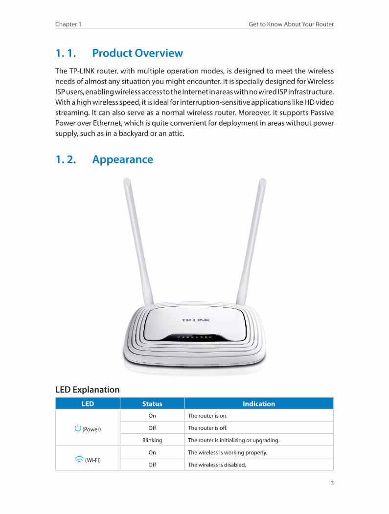
1. 1. Product OverviewThe TP-LINK router, with multiple operation modes, is designed to meet the wireless needs of almost any situation you might encounter. It is specially designed for Wireless ISP users, enabling wireless access to the Internet in areas with no wired ISP infrastructure. With a high wireless speed, it is ideal for interruption-sensitive applications like HD video streaming. It can also serve as a normal wireless router. Moreover, it supports Passive Power over Ethernet, which is quite convenient for deployment in areas without power supply, such as in a backyard or an attic.
1. 2. Appearance
LED ExplanationLED Status Indication
(Power)
On The router is on.
Off The router is off.
Blinking The router is initializing or upgrading.
(Wi-Fi)On The wireless is working properly.
Off The wireless is disabled.
4
Chapter 1 Get to Know About Your Router
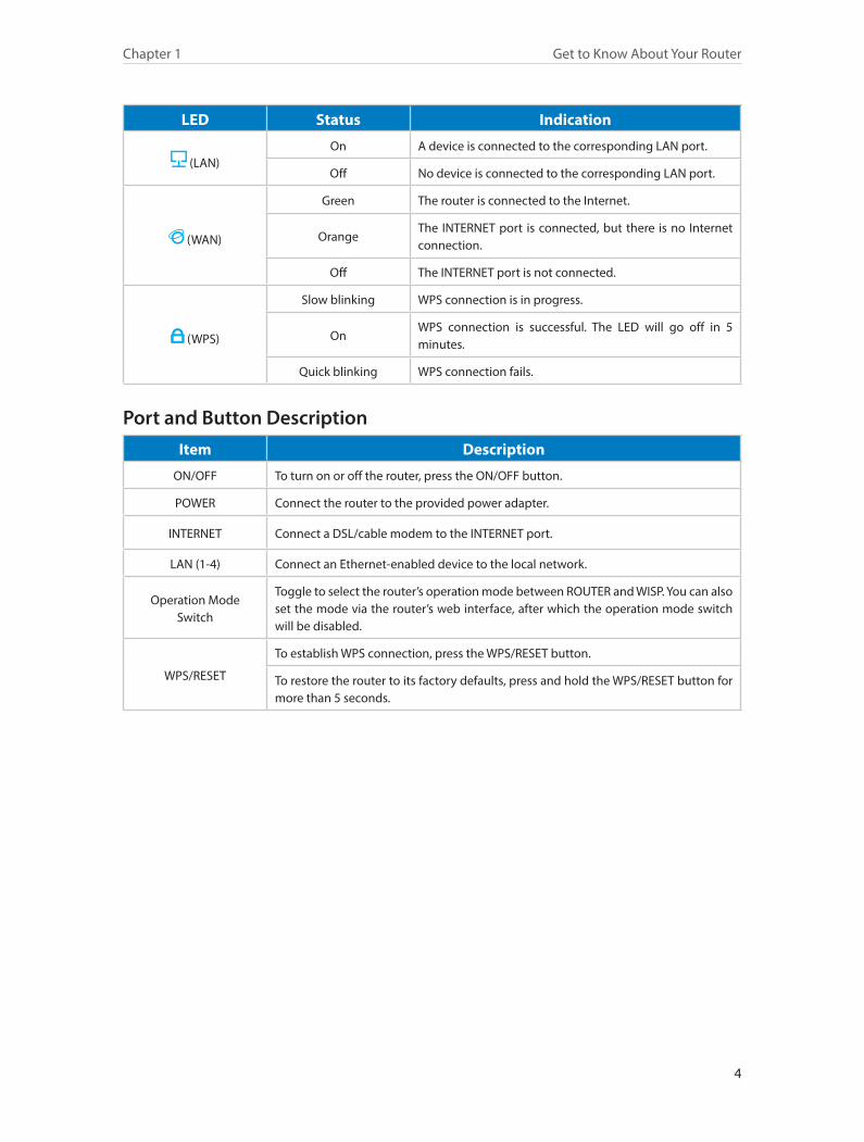
LED Status Indication
(LAN)On A device is connected to the corresponding LAN port.
Off No device is connected to the corresponding LAN port.
(WAN)
Green The router is connected to the Internet.
OrangeThe INTERNET port is connected, but there is no Internet connection.
Off The INTERNET port is not connected.
(WPS)
Slow blinking WPS connection is in progress.
OnWPS connection is successful. The LED will go off in 5 minutes.
Quick blinking WPS connection fails.
Port and Button DescriptionItem Description
ON/OFF To turn on or off the router, press the ON/OFF button.
POWER Connect the router to the provided power adapter.
INTERNET Connect a DSL/cable modem to the INTERNET port.
LAN (1-4) Connect an Ethernet-enabled device to the local network.
Operation Mode Switch
Toggle to select the router’s operation mode between ROUTER and WISP. You can also set the mode via the router’s web interface, after which the operation mode switch will be disabled.
WPS/RESET
To establish WPS connection, press the WPS/RESET button.
To restore the router to its factory defaults, press and hold the WPS/RESET button for more than 5 seconds.
Chapter 2
Connect the Hardware
This chapter contains the following sections:
• Position Your Router
• Connect Your Router
6
Chapter 2 Connect the Hardware
2. 1. Position Your Router• The router should not be located where it will be exposed to moisture or excessive
heat.
• Place the router in a location where it can be connected to devices as well as to a power source.
• Make sure the cables and power cord are safely placed out of the way so that they do not create a tripping hazard.
• The router can be placed on a shelf or desktop.
• Keep the router away from the strong electromagnetic radiation and the device of electromagnetic sensitive.
2. 2. Connect Your RouterThere are three operation modes supported by this router: WISP Client Router, Standard Wireless Router and Repeater. Please determine the operation mode you need and carry out the corresponding steps.
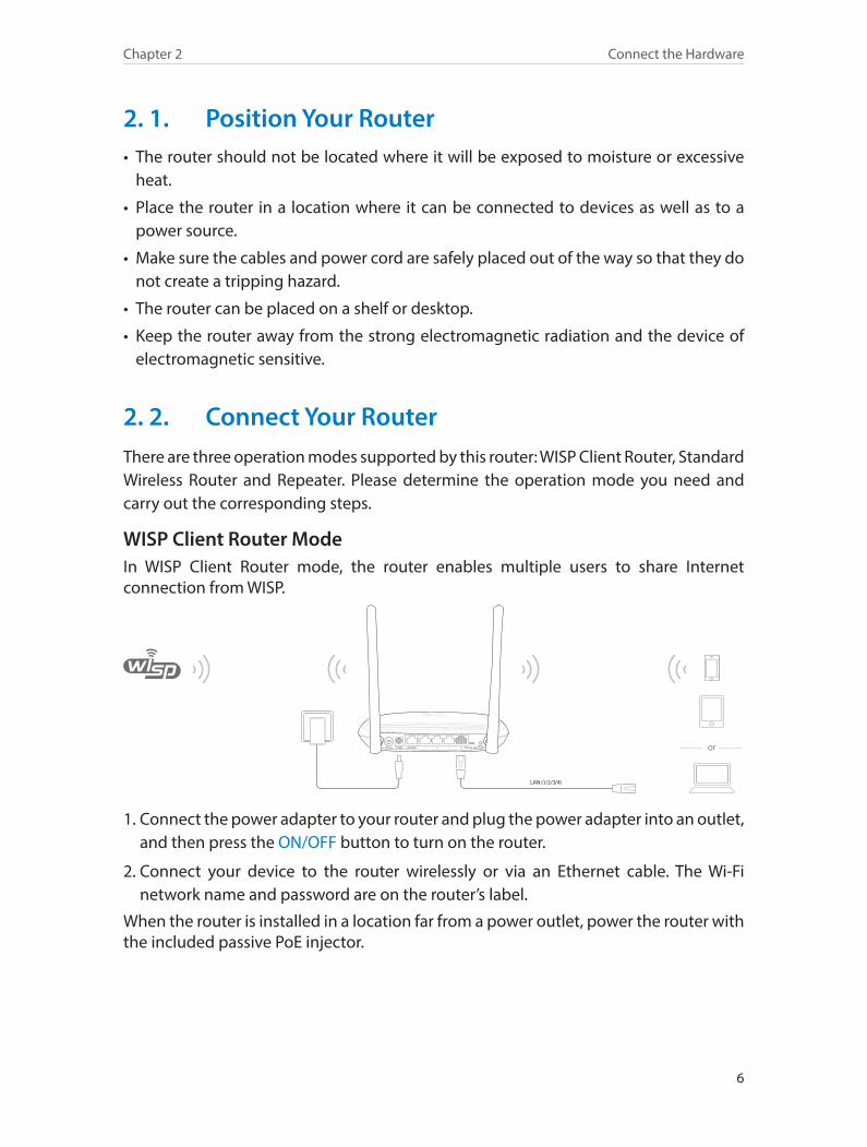
WISP Client Router ModeIn WISP Client Router mode, the router enables multiple users to share Internet connection from WISP.
LAN (1/2/3/4)
ON/OFF POWER INTERNET ROUTER WISP1 2 3 4WPS/RESET or
1. Connect the power adapter to your router and plug the power adapter into an outlet, and then press the ON/OFF button to turn on the router.
2. Connect your device to the router wirelessly or via an Ethernet cable. The Wi-Fi network name and password are on the router’s label.
When the router is installed in a location far from a power outlet, power the router with the included passive PoE injector.
7
Chapter 2 Connect the Hardware
up to 30 meters
ON/OFF POWER INTERNET ROUTER WISP1 2 3 4WPS/RESET
Passive PoE Injector
or
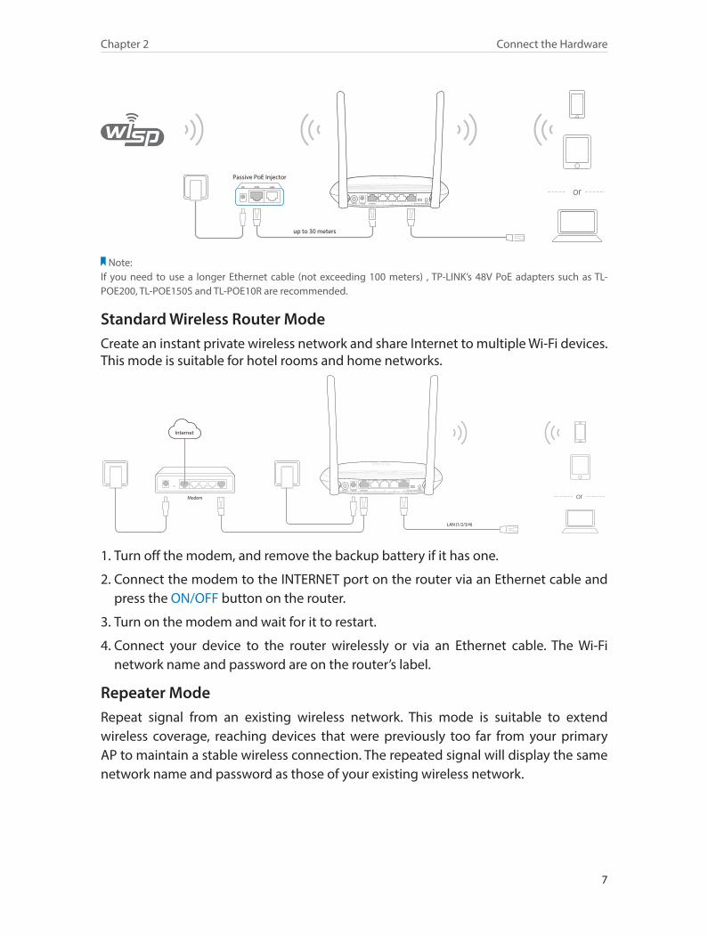
Note: If you need to use a longer Ethernet cable (not exceeding 100 meters) , TP-LINK’s 48V PoE adapters such as TL-POE200, TL-POE150S and TL-POE10R are recommended.
Standard Wireless Router ModeCreate an instant private wireless network and share Internet to multiple Wi-Fi devices. This mode is suitable for hotel rooms and home networks.
Modem
LAN (1/2/3/4)
ON/OFF POWER INTERNET ROUTER WISP1 2 3 4WPS/RESET
or
Internet
1. Turn off the modem, and remove the backup battery if it has one.
2. Connect the modem to the INTERNET port on the router via an Ethernet cable and press the ON/OFF button on the router.
3. Turn on the modem and wait for it to restart.
4. Connect your device to the router wirelessly or via an Ethernet cable. The Wi-Fi network name and password are on the router’s label.
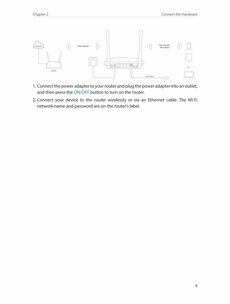
Repeater ModeRepeat signal from an existing wireless network. This mode is suitable to extend wireless coverage, reaching devices that were previously too far from your primary AP to maintain a stable wireless connection. The repeated signal will display the same network name and password as those of your existing wireless network.
8
Chapter 2 Connect the Hardware
Main AP
The main AP’s Wi-Fi Name
Main network
LAN (1/2/3/4)
ON/OFF POWER INTERNET ROUTER WISP1 2 3 4WPS/RESET or
Internet
1. Connect the power adapter to your router and plug the power adapter into an outlet, and then press the ON/OFF button to turn on the router.
2. Connect your device to the router wirelessly or via an Ethernet cable. The Wi-Fi network name and password are on the router’s label.
Chapter 3
Set Up Internet Connection Via Quick Setup Wizard
This chapter introduces how to connect your router to the Internet via the web-based Quick Setup Wizard.
This chapter contains the following sections:
• Log into the Router
• Configure the Router
10
Chapter 3 Set Up Internet Connection Via Quick Setup Wizard
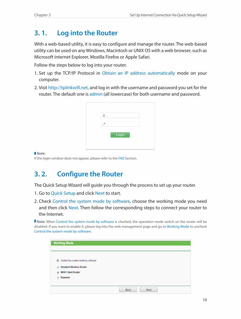
3. 1. Log into the RouterWith a web-based utility, it is easy to configure and manage the router. The web-based utility can be used on any Windows, Macintosh or UNIX OS with a web browser, such as Microsoft Internet Explorer, Mozilla Firefox or Apple Safari.
Follow the steps below to log into your router.
1. Set up the TCP/IP Protocol in Obtain an IP address automatically mode on your computer.
2. Visit http://tplinkwifi.net, and log in with the username and password you set for the router. The default one is admin (all lowercase) for both username and password.
Note:If the login window does not appear, please refer to the FAQ Section.
3. 2. Configure the RouterThe Quick Setup Wizard will guide you through the process to set up your router.
1. Go to Quick Setup and click Next to start.
2. Check Control the system mode by software, choose the working mode you need and then click Next. Then follow the corresponding steps to connect your router to the Internet.
Note: When Control the system mode by software is checked, the operation mode switch on the router will be disabled. If you want to enable it, please log into the web management page and go to Working Mode to uncheck Control the system mode by software.
11
Chapter 3 Set Up Internet Connection Via Quick Setup Wizard
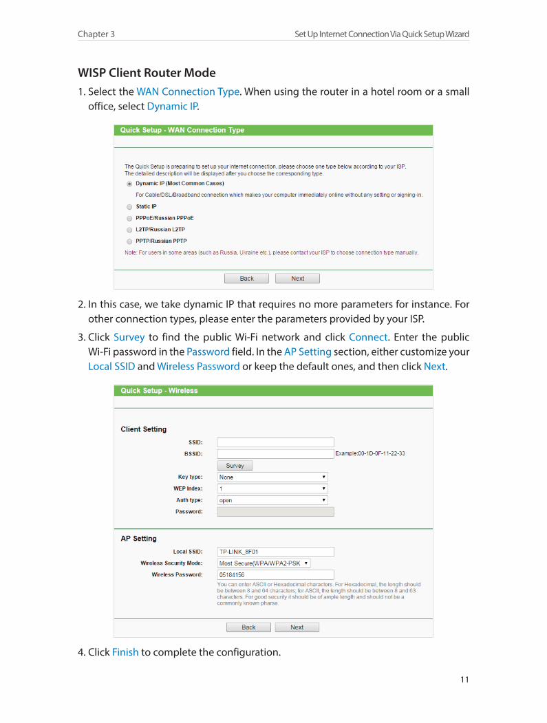
WISP Client Router Mode1. Select the WAN Connection Type. When using the router in a hotel room or a small
office, select Dynamic IP.
2. In this case, we take dynamic IP that requires no more parameters for instance. For other connection types, please enter the parameters provided by your ISP.
3. Click Survey to find the public Wi-Fi network and click Connect. Enter the public Wi-Fi password in the Password field. In the AP Setting section, either customize your Local SSID and Wireless Password or keep the default ones, and then click Next.
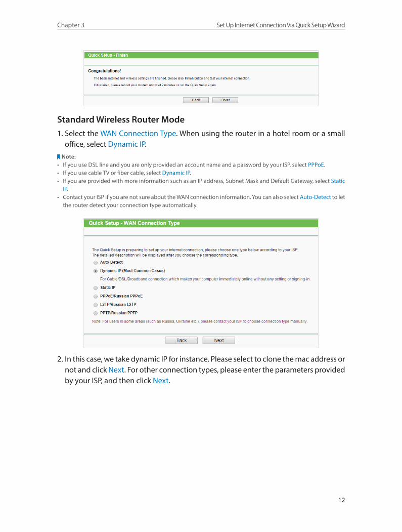
4. Click Finish to complete the configuration.
12
Chapter 3 Set Up Internet Connection Via Quick Setup Wizard
Standard Wireless Router Mode 1. Select the WAN Connection Type. When using the router in a hotel room or a small
office, select Dynamic IP.Note:
• If you use DSL line and you are only provided an account name and a password by your ISP, select PPPoE. • If you use cable TV or fiber cable, select Dynamic IP. • If you are provided with more information such as an IP address, Subnet Mask and Default Gateway, select Static
IP. • Contact your ISP if you are not sure about the WAN connection information. You can also select Auto-Detect to let
the router detect your connection type automatically.
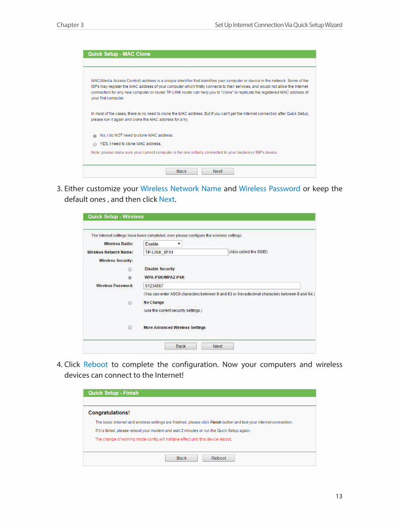
2. In this case, we take dynamic IP for instance. Please select to clone the mac address or not and click Next. For other connection types, please enter the parameters provided by your ISP, and then click Next.
13
Chapter 3 Set Up Internet Connection Via Quick Setup Wizard
3. Either customize your Wireless Network Name and Wireless Password or keep the default ones , and then click Next.
4. Click Reboot to complete the configuration. Now your computers and wireless devices can connect to the Internet!
14
Chapter 3 Set Up Internet Connection Via Quick Setup Wizard
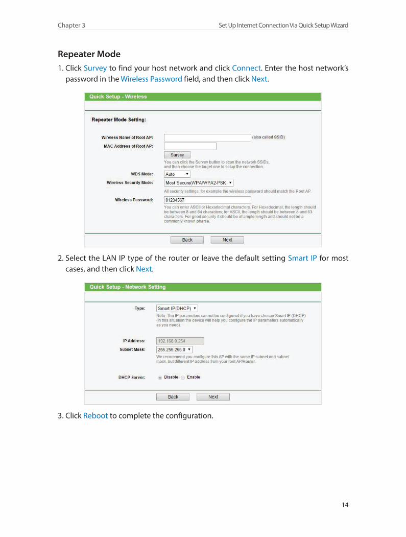
Repeater Mode1. Click Survey to find your host network and click Connect. Enter the host network’s
password in the Wireless Password field, and then click Next.
2. Select the LAN IP type of the router or leave the default setting Smart IP for most cases, and then click Next.
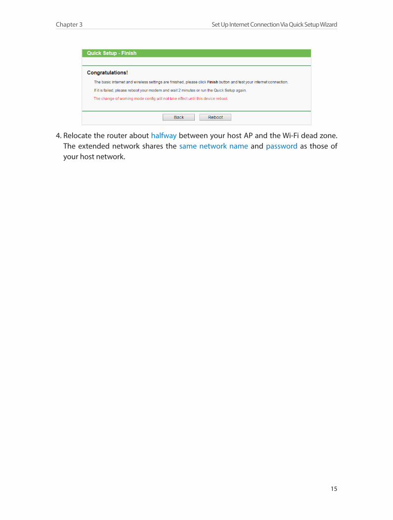
3. Click Reboot to complete the configuration.
15
Chapter 3 Set Up Internet Connection Via Quick Setup Wizard
4. Relocate the router about halfway between your host AP and the Wi-Fi dead zone. The extended network shares the same network name and password as those of your host network.
Chapter 4
Configure the Router in WISP Client Router Mode
This chapter presents how to configure the various features of the router working as a WISP Client Router.
This chapter contains the following sections:
• Status
• WPS
• Working Mode
• Network
• Wireless
• Guest Network
• DHCP
• Forwarding
• Security
• Parental Controls
• Access Control
• Advanced Routing
• Bandwidth Control
• IP&MAC Binding
• Dynamic DNS
• System Tools
• Logout
17
Chapter 4 Configure the Router in WISP Client Router Mode
4. 1. Status1. Visit http://tplinkwifi.net, and log in with the username and password you set for
the router.
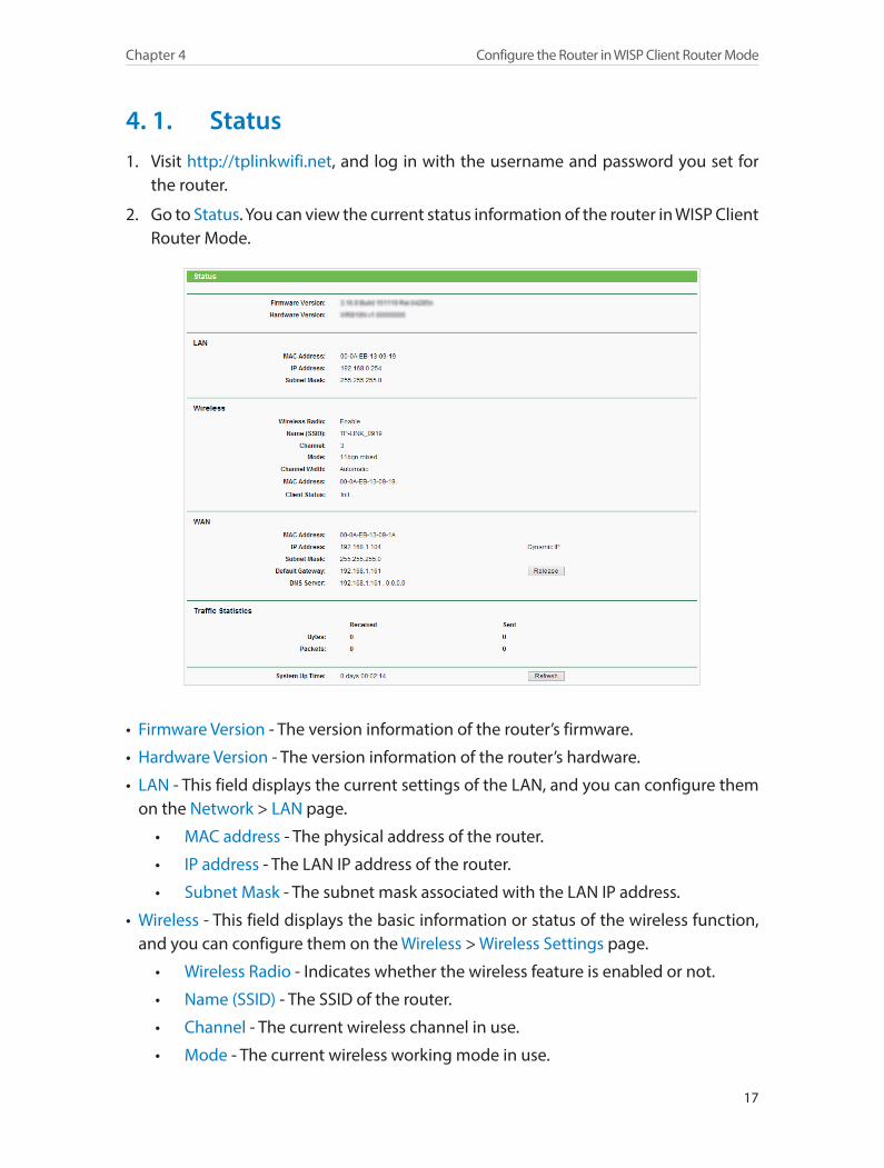
2. Go to Status. You can view the current status information of the router in WISP Client Router Mode.
• Firmware Version - The version information of the router’s firmware.
• Hardware Version - The version information of the router’s hardware.
• LAN - This field displays the current settings of the LAN, and you can configure them on the Network > LAN page.
• MAC address - The physical address of the router.
• IP address - The LAN IP address of the router.
• Subnet Mask - The subnet mask associated with the LAN IP address.
• Wireless - This field displays the basic information or status of the wireless function, and you can configure them on the Wireless > Wireless Settings page.
• Wireless Radio - Indicates whether the wireless feature is enabled or not.
• Name (SSID) - The SSID of the router.
• Channel - The current wireless channel in use.
• Mode - The current wireless working mode in use.
18
Chapter 4 Configure the Router in WISP Client Router Mode
• Channel Width - The current wireless channel width in use.
• MAC Address - The physical address of the router.
• Client Status - The status of client. Init: Connection is down; Scan: Try to find the AP; Auth: Try to authenticate; ASSOC: Try to associate; Run: Associated successfully.
• WAN - This field displays the current settings of the WAN, and you can configure them on the Network > WAN page.
• MAC Address - The physical address of the WAN port.
• IP Address - The current WAN (Internet) IP Address. This field will be blank or 0.0.0.0 if the IP Address is assigned dynamically and there is no Internet connection.
• Subnet Mask - The subnet mask associated with the WAN IP Address.
• Default Gateway - The Gateway currently used is shown here. When you use Dynamic IP as the WAN connection type, click Renew or Release here to obtain new IP parameters dynamically from the ISP or release them.
• DNS Server - The IP addresses of DNS (Domain Name System) server.
• Traffic Statistics - The router’s traffic statistics.
• Received (Bytes) - Traffic in bytes received from the WAN port.
• Received (Packets) - Traffic in packets received from the WAN port.
• Sent (Bytes) - Traffic in bytes sent out from the WAN port.
• Sent (Packets) - Traffic in packets sent out from the WAN port.
• System Up Time - The length of the time since the router was last powered on or reset.
Click Refresh to get the latest status and settings of the router.
4. 2. WPSWPS (Wi-Fi Protected Setup) can help you to quickly and securely connect to a network. This section will guide you to add a new wireless device to your router’s network quickly via WPS.
Note:The WPS function cannot be configured if the wireless function of the router is disabled. Please make sure the wireless function is enabled before configuration.
1. Visit http://tplinkwifi.net, and log in with the username and password you set for the router.
2. Go to WPS.
3. Follow one of the following three methods to connect your client device to the router’s Wi-Fi network.
19
Chapter 4 Configure the Router in WISP Client Router Mode
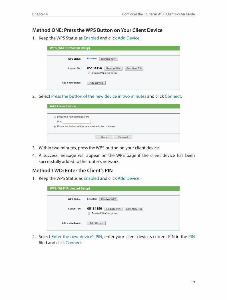
Method ONE: Press the WPS Button on Your Client Device1. Keep the WPS Status as Enabled and click Add Device.
2. Select Press the button of the new device in two minutes and click Connect.
3. Within two minutes, press the WPS button on your client device.
4. A success message will appear on the WPS page if the client device has been successfully added to the router’s network.
Method TWO: Enter the Client’s PIN1. Keep the WPS Status as Enabled and click Add Device.
2. Select Enter the new device’s PIN, enter your client device’s current PIN in the PIN filed and click Connect.
20
Chapter 4 Configure the Router in WISP Client Router Mode
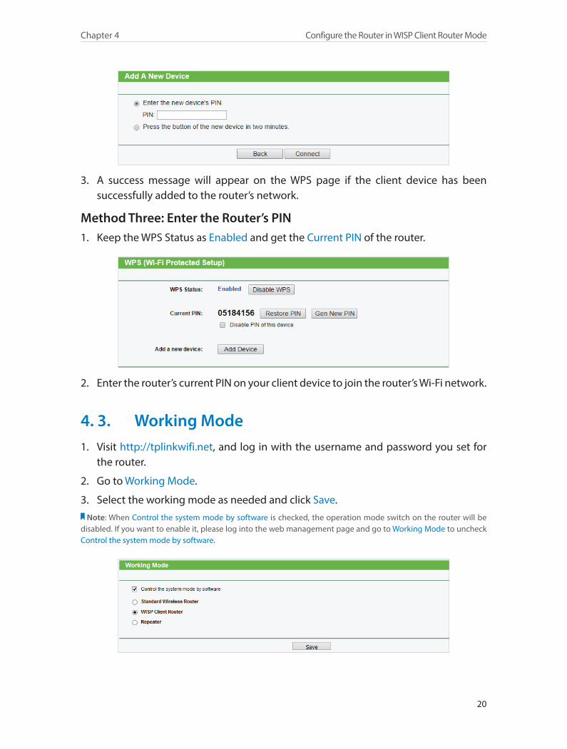
3. A success message will appear on the WPS page if the client device has been successfully added to the router’s network.
Method Three: Enter the Router’s PIN1. Keep the WPS Status as Enabled and get the Current PIN of the router.
2. Enter the router’s current PIN on your client device to join the router’s Wi-Fi network.
4. 3. Working Mode1. Visit http://tplinkwifi.net, and log in with the username and password you set for
the router.
2. Go to Working Mode.
3. Select the working mode as needed and click Save.Note: When Control the system mode by software is checked, the operation mode switch on the router will be
disabled. If you want to enable it, please log into the web management page and go to Working Mode to uncheck Control the system mode by software.
21
Chapter 4 Configure the Router in WISP Client Router Mode
4. 4. Network
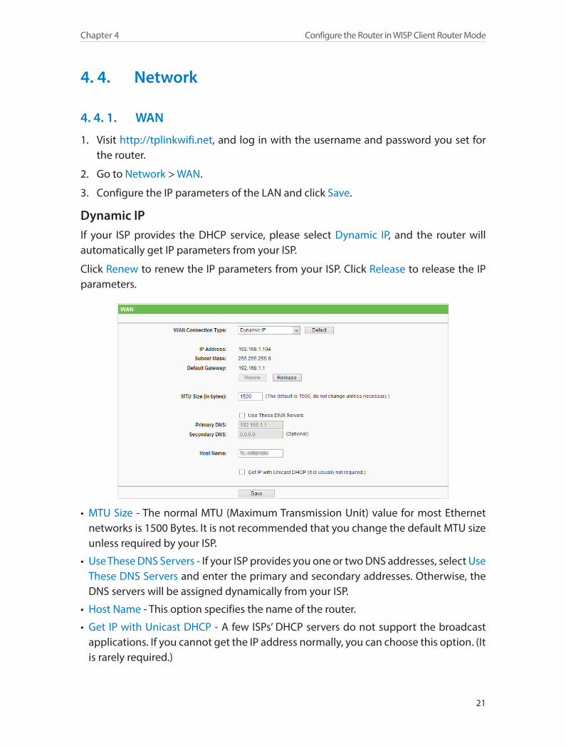
4. 4. 1. WAN
1. Visit http://tplinkwifi.net, and log in with the username and password you set for the router.
2. Go to Network > WAN.
3. Configure the IP parameters of the LAN and click Save.
Dynamic IPIf your ISP provides the DHCP service, please select Dynamic IP, and the router will automatically get IP parameters from your ISP.
Click Renew to renew the IP parameters from your ISP. Click Release to release the IP parameters.
• MTU Size - The normal MTU (Maximum Transmission Unit) value for most Ethernet networks is 1500 Bytes. It is not recommended that you change the default MTU size unless required by your ISP.
• Use These DNS Servers - If your ISP provides you one or two DNS addresses, select Use These DNS Servers and enter the primary and secondary addresses. Otherwise, the DNS servers will be assigned dynamically from your ISP.
• Host Name - This option specifies the name of the router.
• Get IP with Unicast DHCP - A few ISPs’ DHCP servers do not support the broadcast applications. If you cannot get the IP address normally, you can choose this option. (It is rarely required.)
22
Chapter 4 Configure the Router in WISP Client Router Mode
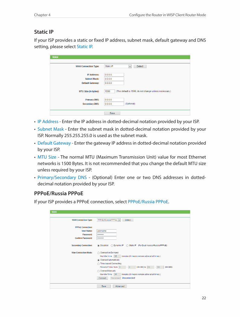
Static IPIf your ISP provides a static or fixed IP address, subnet mask, default gateway and DNS setting, please select Static IP.
• IP Address - Enter the IP address in dotted-decimal notation provided by your ISP.
• Subnet Mask - Enter the subnet mask in dotted-decimal notation provided by your ISP. Normally 255.255.255.0 is used as the subnet mask.
• Default Gateway - Enter the gateway IP address in dotted-decimal notation provided by your ISP.
• MTU Size - The normal MTU (Maximum Transmission Unit) value for most Ethernet networks is 1500 Bytes. It is not recommended that you change the default MTU size unless required by your ISP.
• Primary/Secondary DNS - (Optional) Enter one or two DNS addresses in dotted-decimal notation provided by your ISP.
PPPoE/Russia PPPoEIf your ISP provides a PPPoE connection, select PPPoE/Russia PPPoE.
23
Chapter 4 Configure the Router in WISP Client Router Mode
• User Name/Password - Enter the user name and password provided by your ISP. These fields are case-sensitive.
• Confirm Password - Enter the Password provided by your ISP again to ensure the password you entered is correct.
• Secondary Connection - It’s available only for PPPoE connection. If your ISP provides an extra connection type, select Dynamic IP or Static IP to activate the secondary connection.
• WAN Connection Mode
• Connect on Demand - In this mode, the Internet connection can be terminated automatically after a specified inactivity period (Max Idle Time) and be re-established when you attempt to access the Internet again. If you want to keep your Internet connection active all the time, please enter 0 in the Max Idle Time field. Otherwise, enter the number of minutes you want to have elapsed before your Internet access disconnects.
• Connect Automatically - The connection can be re-established automatically when it is down.
• Time-based Connecting - The connection will only be established in the period from the start time to the end time (both are in HH:MM format).
• Connect Manually - You can click Connect/Disconnect to connect/disconnect immediately. This mode also supports the Max Idle Time function as Connect on Demand mode. The Internet connection can be disconnected automatically after a specified inactivity period (Max Idle Time) and not be able to re-establish when you attempt to access the Internet again.
Note:1. Only when you have configured the system time on the System Tools > Time Settings page, will the Time-based
Connecting function take effect.2. Sometimes the connection cannot be terminated although you have specified the Max Idle Time because some
applications are visiting the Internet continually in the background.
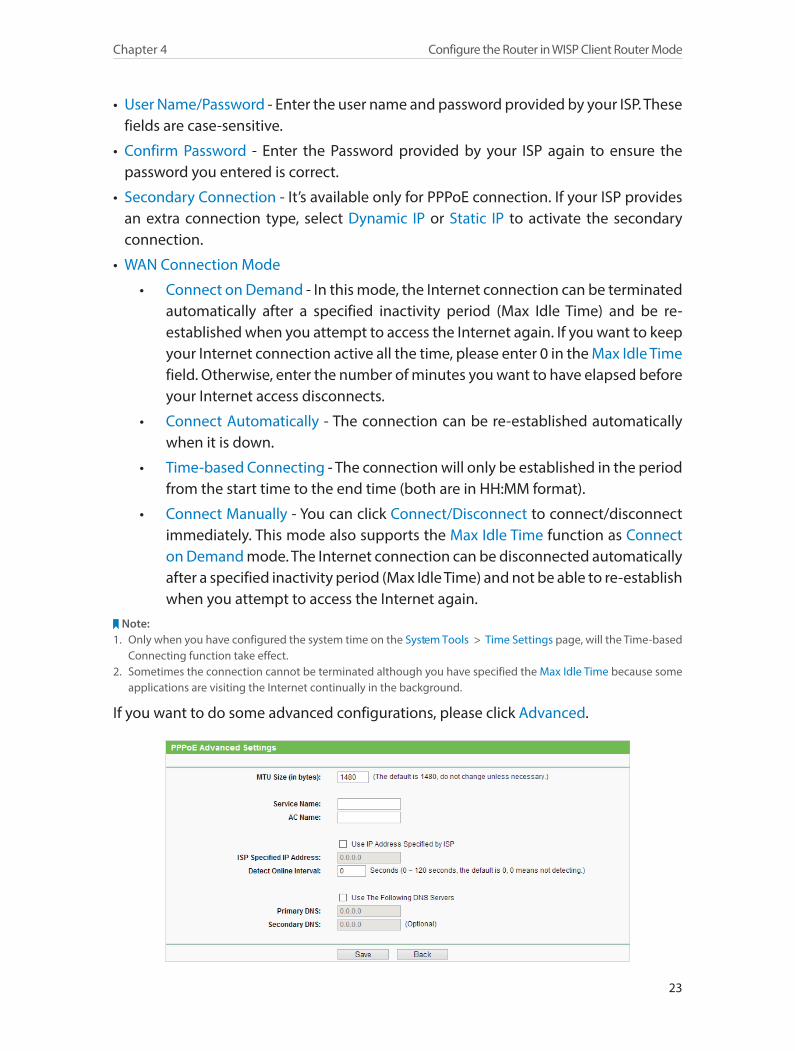
If you want to do some advanced configurations, please click Advanced.
24
Chapter 4 Configure the Router in WISP Client Router Mode
• MTU Size - The default MTU size is 1480 bytes. It is not recommended that you change the default MTU size unless required by your ISP.
• Service Name/AC Name - The service name and AC (Access Concentrator) name should not be configured unless you are sure it is necessary for your ISP. In most cases, leaving these fields blank will work.
• ISP Specified IP Address - If your ISP does not automatically assign IP addresses to the router, please select Use IP address specified by ISP and enter the IP address provided by your ISP in dotted-decimal notation.
• Detect Online Interval - The router will detect Access Concentrator online at every interval. The default value is 0. You can input the value between 0 and 120. The value 0 means no detect.
• Primary DNS/Secondary DNS - If your ISP does not automatically assign DNS addresses to the router, please select Use the following DNS servers and enter the IP address in dotted-decimal notation of your ISP’s primary DNS server. If a secondary DNS server address is available, enter it as well.
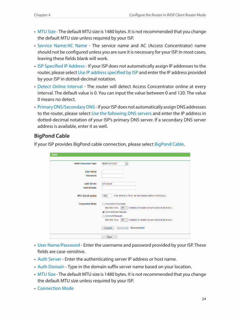
BigPond CableIf your ISP provides BigPond cable connection, please select BigPond Cable.
• User Name/Password - Enter the username and password provided by your ISP. These fields are case-sensitive.
• Auth Server - Enter the authenticating server IP address or host name.
• Auth Domain - Type in the domain suffix server name based on your location.
• MTU Size - The default MTU size is 1480 bytes. It is not recommended that you change the default MTU size unless required by your ISP.
• Connection Mode
25
Chapter 4 Configure the Router in WISP Client Router Mode
• Connect on Demand - In this mode, the Internet connection can be terminated automatically after a specified inactivity period (Max Idle Time) and be re-established when you attempt to access the Internet again. If you want to keep your Internet connection active all the time, please enter 0 in the Max Idle Time field. Otherwise, enter the number of minutes you want to have elapsed before your Internet access disconnects.
• Connect Automatically - The connection can be re-established automatically when it is down.
• Connect Manually - You can click Connect/Disconnect to connect/disconnect immediately. This mode also supports the Max Idle Time function as Connect on Demand mode. The Internet connection can be disconnected automatically after a specified inactivity period (Max Idle Time) and not be able to re-establish when you attempt to access the Internet again.
Note:Sometimes the connection cannot be terminated although you have specified the Max Idle Time because some applications are visiting the Internet continually in the background.
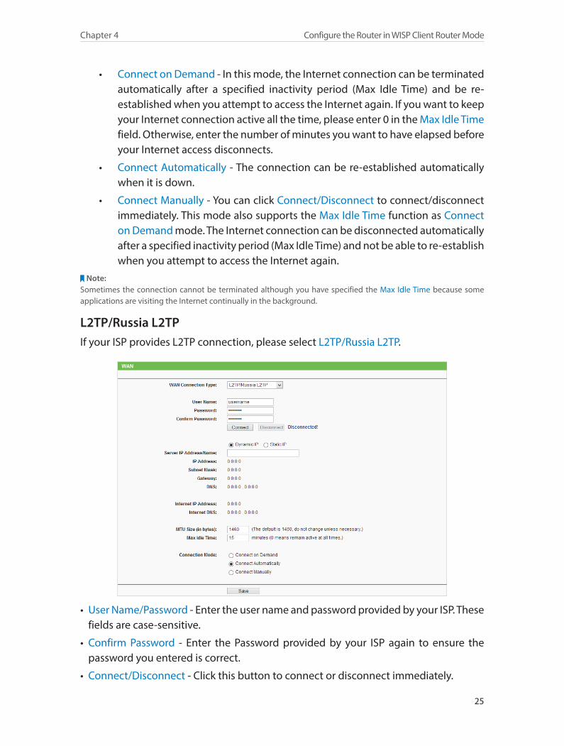
L2TP/Russia L2TPIf your ISP provides L2TP connection, please select L2TP/Russia L2TP.
• User Name/Password - Enter the user name and password provided by your ISP. These fields are case-sensitive.
• Confirm Password - Enter the Password provided by your ISP again to ensure the password you entered is correct.
• Connect/Disconnect - Click this button to connect or disconnect immediately.
26
Chapter 4 Configure the Router in WISP Client Router Mode
• Dynamic IP/ Static IP - Select either as required by your ISP. If Static IP is selected, please enter the IP address, subnet marsk, gateway and DNS also provided by your ISP.
• Internet IP Address/ Internet DNS - The Internet IP address and DNS server address assigned by L2TP server.
• Connection Mode
• Connect on Demand - In this mode, the Internet connection can be terminated automatically after a specified inactivity period (Max Idle Time) and be re-established when you attempt to access the Internet again. If you want to keep your Internet connection active all the time, please enter 0 in the Max Idle Time field. Otherwise, enter the number of minutes you want to have elapsed before your Internet access disconnects.
• Connect Automatically - The connection can be re-established automatically when it is down.
• Connect Manually - You can click Connect/Disconnect to connect/disconnect immediately. This mode also supports the Max Idle Time function as Connect on Demand mode. The Internet connection can be disconnected automatically after a specified inactivity period (Max Idle Time) and not be able to re-establish when you attempt to access the Internet again.
Note:Sometimes the connection cannot be terminated although you have specified the Max Idle Time because some applications are visiting the Internet continually in the background.
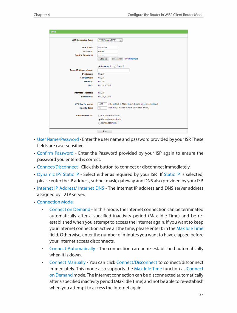
PPTP/Russia PPTPIf your ISP provides PPTP connection, please select PPTP/Russia PPTP.
27
Chapter 4 Configure the Router in WISP Client Router Mode
• User Name/Password - Enter the user name and password provided by your ISP. These fields are case-sensitive.
• Confirm Password - Enter the Password provided by your ISP again to ensure the password you entered is correct.
• Connect/Disconnect - Click this button to connect or disconnect immediately.
• Dynamic IP/ Static IP - Select either as required by your ISP. If Static IP is selected, please enter the IP address, subnet mask, gateway and DNS also provided by your ISP.
• Internet IP Address/ Internet DNS - The Internet IP address and DNS server address assigned by L2TP server.
• Connection Mode
• Connect on Demand - In this mode, the Internet connection can be terminated automatically after a specified inactivity period (Max Idle Time) and be re-established when you attempt to access the Internet again. If you want to keep your Internet connection active all the time, please enter 0 in the Max Idle Time field. Otherwise, enter the number of minutes you want to have elapsed before your Internet access disconnects.
• Connect Automatically - The connection can be re-established automatically when it is down.
• Connect Manually - You can click Connect/Disconnect to connect/disconnect immediately. This mode also supports the Max Idle Time function as Connect on Demand mode. The Internet connection can be disconnected automatically after a specified inactivity period (Max Idle Time) and not be able to re-establish when you attempt to access the Internet again.
28
Chapter 4 Configure the Router in WISP Client Router Mode
Note:Sometimes the connection cannot be terminated although you have specified the Max Idle Time because some applications are visiting the Internet continually in the background.
4. 4. 2. MAC Clone
1. Visit http://tplinkwifi.net, and log in with the username and password you set for the router.
2. Go to Network > MAC Clone.
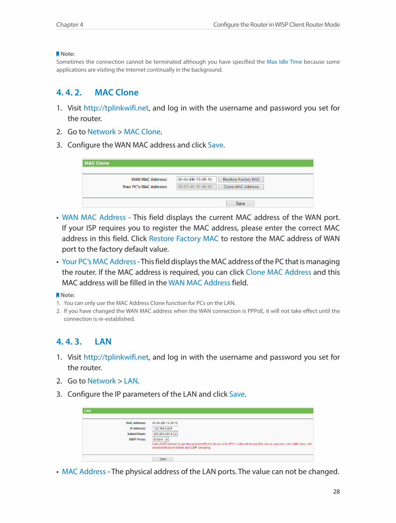
3. Configure the WAN MAC address and click Save.
• WAN MAC Address - This field displays the current MAC address of the WAN port. If your ISP requires you to register the MAC address, please enter the correct MAC address in this field. Click Restore Factory MAC to restore the MAC address of WAN port to the factory default value.
• Your PC’s MAC Address - This field displays the MAC address of the PC that is managing the router. If the MAC address is required, you can click Clone MAC Address and this MAC address will be filled in the WAN MAC Address field.
Note:1. You can only use the MAC Address Clone function for PCs on the LAN.2. If you have changed the WAN MAC address when the WAN connection is PPPoE, it will not take effect until the
connection is re-established.
4. 4. 3. LAN
1. Visit http://tplinkwifi.net, and log in with the username and password you set for the router.
2. Go to Network > LAN.
3. Configure the IP parameters of the LAN and click Save.
• MAC Address - The physical address of the LAN ports. The value can not be changed.
29
Chapter 4 Configure the Router in WISP Client Router Mode
• IP Address - Enter the IP address in dotted-decimal notation of your router (factory default - 192.168.0.1).
• Subnet Mask - An address code that determines the size of the network. Normally 255.255.255.0 is used as the subnet mask.
• IGMP Proxy - The Internet Group Management Protocol (IGMP) feature allow you to watch TV on IPTV-supported devices in the LAN .
Note:1. If you have changed the IP address, you must use the new IP address to login.2. If the new IP address you set is not in the same subnet as the old one, the IP Address pool in the DHCP Server will
be configured automatically, but the Virtual Server and DMZ Host will not take effect until they are re-configured.
4. 5. Wireless
4. 5. 1. Wireless Settings
1. Visit http://tplinkwifi.net, and log in with the username and password you set for the router.
2. Go to Wireless > Wireless Settings.
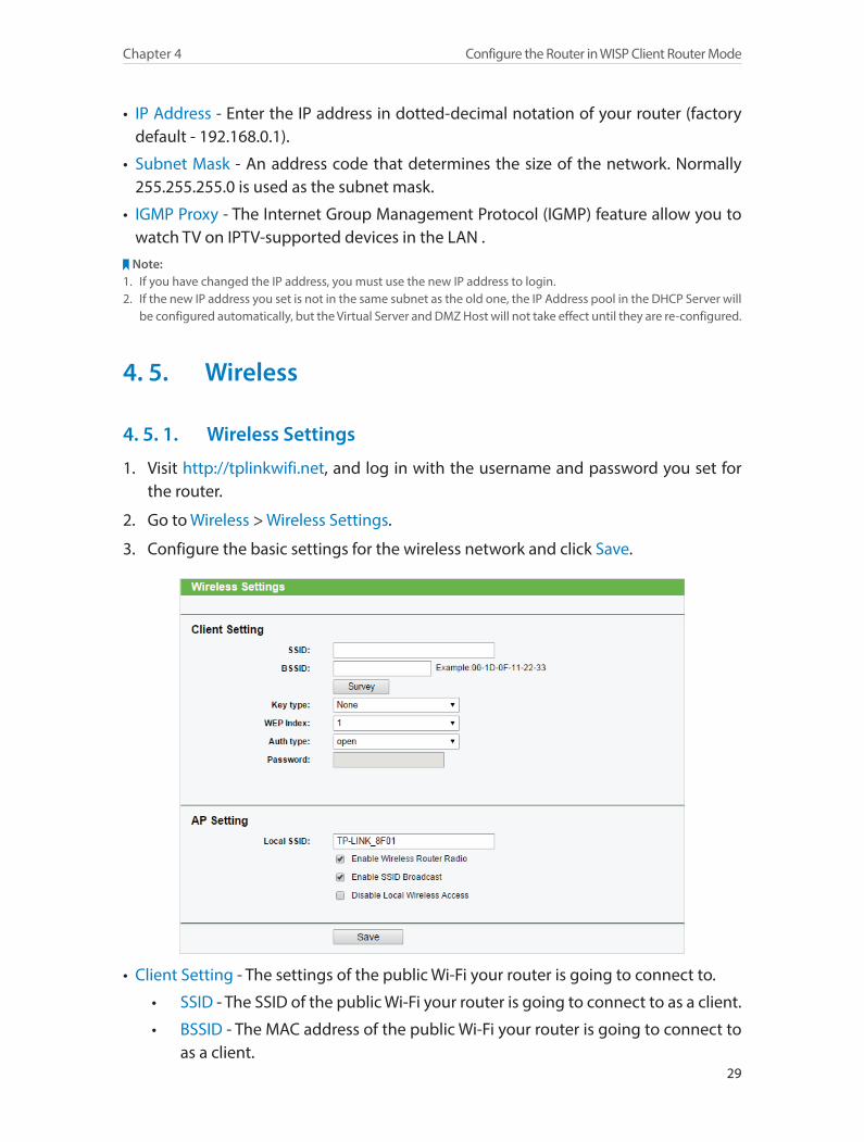
3. Configure the basic settings for the wireless network and click Save.
• Client Setting - The settings of the public Wi-Fi your router is going to connect to.
• SSID - The SSID of the public Wi-Fi your router is going to connect to as a client.
• BSSID - The MAC address of the public Wi-Fi your router is going to connect to as a client.
30
Chapter 4 Configure the Router in WISP Client Router Mode
• Survey - Click this button to search the public Wi-Fi.
• Key type - Select the key type according to the public Wi-Fi’s security configuration. It is recommended that the key type is the same as the public Wi-Fi’s security type.
• WEP Index - Select which of the four keys will be used if the key type is WEP (ASCII) or WEP (HEX).
• Auth Type - Select the authorization type if the key type is WEP (ASCII) or WEP (HEX).
• Password - Enter the public Wi-Fi’s password if required.
• AP Setting - The wireless settings of your router.
• Local SSID - Enter a string of up to 32 characters. It is strongly recommended that you change your network name (SSID). This value is case-sensitive. For example, TEST is NOT the same as test.
• Enable Wireless Router Radio - The wireless radio of the router can be enabled or disabled to allow or deny wireless access. If enabled, the wireless clients will be able to access the router.
• Enable SSID Broadcast - If enabled, the router will broadcast the wireless network name (SSID).
• Disable Local Wireless Access - If you select this option, the wireless clients will not be able to connect to the router.
4. 5. 2. Wireless Security
1. Visit http://tplinkwifi.net, and log in with the username and password you set for the router.
2. Go to Wireless > Wireless Security.
3. Configure the security settings of your wireless network and click Save.

31
Chapter 4 Configure the Router in WISP Client Router Mode
• Disable Security - The wireless security function can be enabled or disabled. If disabled, wireless clients can connect to the router without a password. It’s strongly recommended to choose one of the following modes to enable security.
• WPA-PSK/WPA2-Personal - It’s the WPA/WPA2 authentication type based on pre-shared passphrase.
• Version - Select Automatic, WPA-PSK or WPA2-PSK.
• Encryption - Select Automatic, TKIP or AES.
• Wireless Password - Enter ASCII or Hexadecimal characters. For Hexadecimal, the length should be between 8 and 64 characters; for ASCII, the length should be between 8 and 63 characters.
• Group Key Update Period - Specify the group key update interval in seconds. The value can be 0 or at least 30. Enter 0 to disable the update.
• WPA /WPA2-Enterprise - It’s based on Radius Server.
• Version - Select Automatic, WPA or WPA2.
• Encryption - Select Automatic, TKIP or AES.
• Radius Server IP - Enter the IP address of the Radius server.
• Radius Port - Enter the port that Radius server used.
• Radius Password - Enter the password for the Radius server.
• Group Key Update Period - Specify the group key update interval in seconds. The value should be 30 or above. Enter 0 to disable the update.
• WEP - It is based on the IEEE 802.11 standard.

32
Chapter 4 Configure the Router in WISP Client Router Mode
• Type - The default setting is Automatic, which can select Shared Key or Open System authentication type automatically based on the wireless client’s capability and request.
• WEP Key Format - Hexadecimal and ASCII formats are provided here. Hexadecimal format stands for any combination of hexadecimal digits (0-9, a-f, A-F) in the specified length. ASCII format stands for any combination of keyboard characters in the specified length.
• WEP Key (Password) - Select which of the four keys will be used and enter the matching WEP key. Make sure these values are identical on all wireless clients in your network.
• Key Type - Select the WEP key length (64-bit, 128-bit or 152-bit) for encryption. Disabled means this WEP key entry is invalid.
• 64-bit - Enter 10 hexadecimal digits (any combination of 0-9, a-f and A-F. Null key is not permitted) or 5 ASCII characters.
• 128-bit - Enter 26 hexadecimal digits (any combination of 0-9, a-f and A-F. Null key is not permitted) or 13 ASCII characters.
• 152-bit - Enter 32 hexadecimal digits (any combination of 0-9, a-f and A-F. Null key is not permitted) or 16 ASCII characters.
4. 5. 3. Wireless MAC Filtering
Wireless MAC Filtering is used to deny or allow specific wireless client devices to access your network by their MAC addresses.
Deny or allow specific wireless client devices to access my network by their MAC addresses.
For example, you want the wireless client A with the MAC address 00-0A-EB-B0-00-0B and the wireless client B with the MAC address 00-0A-EB-00-07-5F to access the router, but other wireless clients cannot access the router
1. Visit http://tplinkwifi.net, and log in with the username and password you set for the router.
2. Go to Wireless > Wireless MAC Filtering.
3. Click Enable to enable the Wireless MAC Filtering function.
4. Select Allow the stations specified by any enabled entries in the list to access as the filtering rule.
5. Delete all or disable all entries if there are any entries already.
6. Click Add New and fill in the blank.
I want to:
How can I do that?
33
Chapter 4 Configure the Router in WISP Client Router Mode
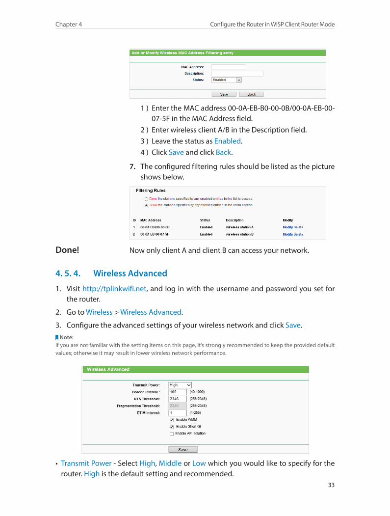
1 ) Enter the MAC address 00-0A-EB-B0-00-0B/00-0A-EB-00-07-5F in the MAC Address field.
2 ) Enter wireless client A/B in the Description field.3 ) Leave the status as Enabled.4 ) Click Save and click Back.
7. The configured filtering rules should be listed as the picture shows below.
Now only client A and client B can access your network.
4. 5. 4. Wireless Advanced
1. Visit http://tplinkwifi.net, and log in with the username and password you set for the router.
2. Go to Wireless > Wireless Advanced.
3. Configure the advanced settings of your wireless network and click Save.Note:
If you are not familiar with the setting items on this page, it’s strongly recommended to keep the provided default values; otherwise it may result in lower wireless network performance.
• Transmit Power - Select High, Middle or Low which you would like to specify for the router. High is the default setting and recommended.
Done!
34
Chapter 4 Configure the Router in WISP Client Router Mode
• Beacon Interval - Enter a value between 40-1000 milliseconds for Beacon Interval here. Beacon Interval value determines the time interval of the beacons. The beacons are the packets sent by the Router to synchronize a wireless network. The default value is 100.
• RTS Threshold - Here you can specify the RTS (Request to Send) Threshold. If the packet is larger than the specified RTS Threshold size, the Router will send RTS frames to a particular receiving station and negotiate the sending of a data frame. The default value is 2346.
• Fragmentation Threshold - This value is the maximum size determining whether packets will be fragmented. Setting a low value for the Fragmentation Threshold may result in poor network performance because of excessive packets. 2346 is the default setting and is recommended.
• DTIM Interval - This value determines the interval of the Delivery Traffic Indication Message (DTIM). A DTIM field is a countdown field informing clients of the next window for listening to broadcast and multicast messages. When the Router has buffered broadcast or multicast messages for associated clients, it sends the next DTIM with a DTIM Interval value. You can specify the value between 1-255 Beacon Intervals. The default value is 1, which indicates the DTIM Interval is the same as Beacon Interval.
• Enable WMM - WMM function can guarantee the packets with high-priority messages being transmitted preferentially. It is strongly recommended to enable this function.
• Enable Short GI - It is recommended to enable this function, for it will increase the data capacity by reducing the guard interval time.
• Enable AP Isolation - This function isolates all connected wireless stations so that wireless stations cannot access each other through WLAN. This function will be disabled if WDS/Bridge is enabled.
4. 5. 5. Wireless Statistics
1. Visit http://tplinkwifi.net, and log in with the username and password you set for the router.
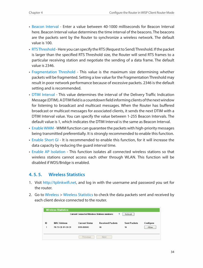
2. Go to Wireless > Wireless Statistics to check the data packets sent and received by each client device connected to the router.

35
Chapter 4 Configure the Router in WISP Client Router Mode
• MAC Address - The MAC address of the connected wireless client.
• Current Status - The running status of the connected wireless client.
• Received Packets - Packets received by the wireless client.
• Sent Packets - Packets sent by the wireless client.
• Configure - The button is used for loading the item to the Wireless MAC Filtering list.
• Allow - If the Wireless MAC Filtering function is enabled, click this button to allow the client to access your network.
• Deny - If the Wireless MAC Filtering function is enabled, click this button to deny the client to access your network.
4. 6. Guest NetworkThis function allows you to provide Wi-Fi access for guests without disclosing your host network. When you have guests in your house, apartment, or workplace, you can create a guest network for them. In addition, you can customize guest network settings to ensure network security and privacy.
1. Visit http://tplinkwifi.net, and log in with the username and password you set for the router.
2. Go to Guest Network > Wireless Settings.
3. Enable the Guest Network function.
4. Create a network name for your guest network.
5. Select the Wireless Security type and create the Password of the guest network.
6. Select Schedule from the Access Time drop-down list and customize it for the guest network.
7. Click Save.
36
Chapter 4 Configure the Router in WISP Client Router Mode
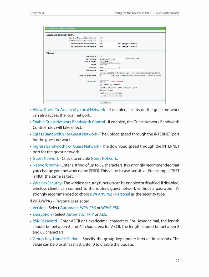
• Allow Guest To Access My Local Network - If enabled, clients on the guest network can also access the local network.
• Enable Guest Network Bandwidth Control - If enabled, the Guest Network Bandwidth Control rules will take effect.
• Egress Bandwidth For Guest Network - The upload speed through the INTERNET port for the guest network.
• Ingress Bandwidth For Guest Network - The download speed through the INTERNET port for the guest network.
• Guest Network - Check to enable Guest Network.
• Network Name - Enter a string of up to 32 characters. It is strongly recommended that you change your network name (SSID). This value is case-sensitive. For example, TEST is NOT the same as test.
• Wireless Security - The wireless security function can be enabled or disabled. If disabled, wireless clients can connect to the router’s guest network without a password. It’s strongly recommended to choose WPA/WPA2 - Personal as the security type.
If WPA/WPA2 - Personal is selected:
• Version - Select Automatic, WPA-PSK or WPA2-PSK.
• Encryption - Select Automatic, TKIP or AES.
• PSK Password - Enter ASCII or Hexadecimal characters. For Hexadecimal, the length should be between 8 and 64 characters; for ASCII, the length should be between 8 and 63 characters.
• Group Key Update Period - Specify the group key update interval in seconds. The value can be 0 or at least 30. Enter 0 to disable the update.
37
Chapter 4 Configure the Router in WISP Client Router Mode
• Access Time - During this period, devices on the guest network can access the router.
4. 7. DHCPBy default, the DHCP (Dynamic Host Configuration Protocol) Server is enabled and the router acts as a DHCP server; it dynamically assigns TCP/IP parameters to client devices from the IP Address Pool. You can change the settings of DHCP Server if necessary, and you can reserve LAN IP addresses for specified client devices.
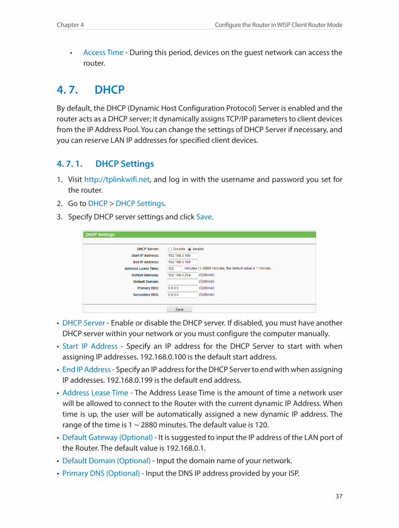
4. 7. 1. DHCP Settings
1. Visit http://tplinkwifi.net, and log in with the username and password you set for the router.
2. Go to DHCP > DHCP Settings.
3. Specify DHCP server settings and click Save.
• DHCP Server - Enable or disable the DHCP server. If disabled, you must have another DHCP server within your network or you must configure the computer manually.
• Start IP Address - Specify an IP address for the DHCP Server to start with when assigning IP addresses. 192.168.0.100 is the default start address.
• End IP Address - Specify an IP address for the DHCP Server to end with when assigning IP addresses. 192.168.0.199 is the default end address.
• Address Lease Time - The Address Lease Time is the amount of time a network user will be allowed to connect to the Router with the current dynamic IP Address. When time is up, the user will be automatically assigned a new dynamic IP address. The range of the time is 1 ~ 2880 minutes. The default value is 120.
• Default Gateway (Optional) - It is suggested to input the IP address of the LAN port of the Router. The default value is 192.168.0.1.
• Default Domain (Optional) - Input the domain name of your network.
• Primary DNS (Optional) - Input the DNS IP address provided by your ISP.

38
Chapter 4 Configure the Router in WISP Client Router Mode
• Secondary DNS (Optional) - Input the IP address of another DNS server if your ISP provides two DNS servers.
Note:To use the DHCP server function of the Router, you must configure all computers on the LAN as Obtain an IP Address automatically.
4. 7. 2. DHCP Client List
1. Visit http://tplinkwifi.net, and log in with the username and password you set for the router.
2. Go to DHCP > DHCP Client List to view the information of the clients connected to the router.
• Client Name - The name of the DHCP client.
• MAC Address - The MAC address of the DHCP client.
• Assigned IP - The IP address that the router has allocated to the DHCP client.
• Lease Time - The time of the dynamic IP leased. After the dynamic IP address has expired, a new dynamic IP address will be automatically assigned to the user.
You cannot change any of the values on this page. To update this page and show the current attached devices, click Refresh.
4. 7. 3. Address Reservation
You can reserve an IP address for a specific client. When you specify a reserved IP address for a PC on the LAN, this PC will always receive the same IP address each time when it accesses the DHCP server.
1. Visit http://tplinkwifi.net, and log in with the username and password you set for the router.
2. Go to DHCP > Address Reservation.
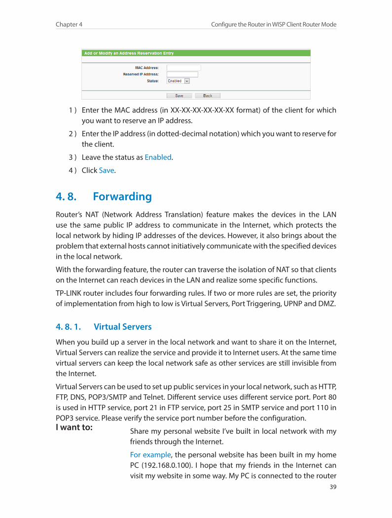
3. Click Add New and fill in the blank.
39
Chapter 4 Configure the Router in WISP Client Router Mode
1 ) Enter the MAC address (in XX-XX-XX-XX-XX-XX format) of the client for which you want to reserve an IP address.
2 ) Enter the IP address (in dotted-decimal notation) which you want to reserve for the client.
3 ) Leave the status as Enabled.
4 ) Click Save.
4. 8. ForwardingRouter’s NAT (Network Address Translation) feature makes the devices in the LAN use the same public IP address to communicate in the Internet, which protects the local network by hiding IP addresses of the devices. However, it also brings about the problem that external hosts cannot initiatively communicate with the specified devices in the local network.
With the forwarding feature, the router can traverse the isolation of NAT so that clients on the Internet can reach devices in the LAN and realize some specific functions.
TP-LINK router includes four forwarding rules. If two or more rules are set, the priority of implementation from high to low is Virtual Servers, Port Triggering, UPNP and DMZ.
4. 8. 1. Virtual Servers
When you build up a server in the local network and want to share it on the Internet, Virtual Servers can realize the service and provide it to Internet users. At the same time virtual servers can keep the local network safe as other services are still invisible from the Internet.
Virtual Servers can be used to set up public services in your local network, such as HTTP, FTP, DNS, POP3/SMTP and Telnet. Different service uses different service port. Port 80 is used in HTTP service, port 21 in FTP service, port 25 in SMTP service and port 110 in POP3 service. Please verify the service port number before the configuration.
Share my personal website I’ve built in local network with my friends through the Internet.
For example, the personal website has been built in my home PC (192.168.0.100). I hope that my friends in the Internet can visit my website in some way. My PC is connected to the router
I want to:
40
Chapter 4 Configure the Router in WISP Client Router Mode
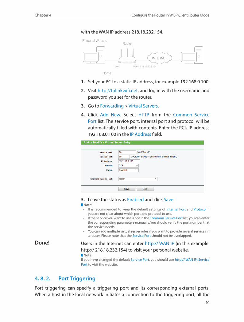
with the WAN IP address 218.18.232.154.
Router
WAN: 218.18.232.154LAN
Home
Personal Website
1. Set your PC to a static IP address, for example 192.168.0.100.
2. Visit http://tplinkwifi.net, and log in with the username and password you set for the router.
3. Go to Forwarding > Virtual Servers.
4. Click Add New. Select HTTP from the Common Service Port list. The service port, internal port and protocol will be automatically filled with contents. Enter the PC’s IP address 192.168.0.100 in the IP Address field.
5. Leave the status as Enabled and click Save.Note:• It is recommended to keep the default settings of Internal Port and Protocol if
you are not clear about which port and protocol to use.• If the service you want to use is not in the Common Service Port list, you can enter
the corresponding parameters manually. You should verify the port number that the service needs.
• You can add multiple virtual server rules if you want to provide several services in a router. Please note that the Service Port should not be overlapped.
Users in the Internet can enter http:// WAN IP (in this example: http:// 218.18.232.154) to visit your personal website.
Note:If you have changed the default Service Port, you should use http:// WAN IP: Service Port to visit the website.
4. 8. 2. Port Triggering
Port triggering can specify a triggering port and its corresponding external ports. When a host in the local network initiates a connection to the triggering port, all the
Done!
41
Chapter 4 Configure the Router in WISP Client Router Mode
external ports will be opened for subsequent connections. The router can record the IP address of the host. When the data from the Internet return to the external ports, the router can forward them to the corresponding host. Port triggering is mainly applied to online games, VoIPs and video players. Common applications include MSN Gaming Zone, Dialpad and Quick Time 4 players, etc.
Follow the steps below to configure the port triggering rules:
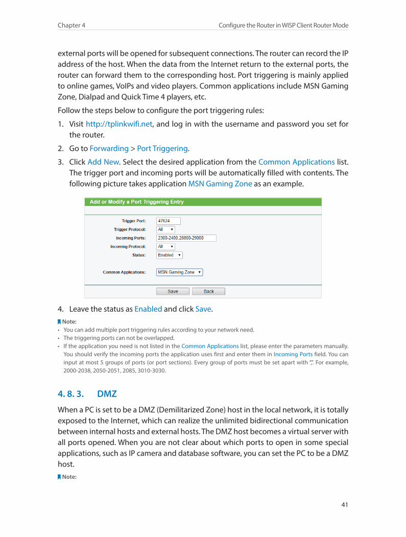
1. Visit http://tplinkwifi.net, and log in with the username and password you set for the router.
2. Go to Forwarding > Port Triggering.
3. Click Add New. Select the desired application from the Common Applications list. The trigger port and incoming ports will be automatically filled with contents. The following picture takes application MSN Gaming Zone as an example.
4. Leave the status as Enabled and click Save.Note:
• You can add multiple port triggering rules according to your network need.• The triggering ports can not be overlapped.• If the application you need is not listed in the Common Applications list, please enter the parameters manually.
You should verify the incoming ports the application uses first and enter them in Incoming Ports field. You can input at most 5 groups of ports (or port sections). Every group of ports must be set apart with “,”. For example, 2000-2038, 2050-2051, 2085, 3010-3030.
4. 8. 3. DMZ
When a PC is set to be a DMZ (Demilitarized Zone) host in the local network, it is totally exposed to the Internet, which can realize the unlimited bidirectional communication between internal hosts and external hosts. The DMZ host becomes a virtual server with all ports opened. When you are not clear about which ports to open in some special applications, such as IP camera and database software, you can set the PC to be a DMZ host.
Note:
42
Chapter 4 Configure the Router in WISP Client Router Mode
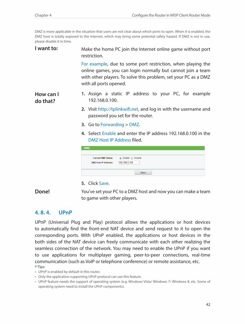
DMZ is more applicable in the situation that users are not clear about which ports to open. When it is enabled, the DMZ host is totally exposed to the Internet, which may bring some potential safety hazard. If DMZ is not in use, please disable it in time.
Make the home PC join the Internet online game without port restriction.
For example, due to some port restriction, when playing the online games, you can login normally but cannot join a team with other players. To solve this problem, set your PC as a DMZ with all ports opened.
1. Assign a static IP address to your PC, for example 192.168.0.100.
2. Visit http://tplinkwifi.net, and log in with the username and password you set for the router.
3. Go to Forwarding > DMZ.
4. Select Enable and enter the IP address 192.168.0.100 in the DMZ Host IP Address filed.
5. Click Save.
You’ve set your PC to a DMZ host and now you can make a team to game with other players.
4. 8. 4. UPnP
UPnP (Universal Plug and Play) protocol allows the applications or host devices to automatically find the front-end NAT device and send request to it to open the corresponding ports. With UPnP enabled, the applications or host devices in the both sides of the NAT device can freely communicate with each other realizing the seamless connection of the network. You may need to enable the UPnP if you want to use applications for multiplayer gaming, peer-to-peer connections, real-time communication (such as VoIP or telephone conference) or remote assistance, etc.
Tips:• UPnP is enabled by default in this router.• Only the application supporting UPnP protocol can use this feature.• UPnP feature needs the support of operating system (e.g. Windows Vista/ Windows 7/ Windows 8, etc. Some of
operating system need to install the UPnP components).
I want to:
How can I do that?
Done!
43
Chapter 4 Configure the Router in WISP Client Router Mode
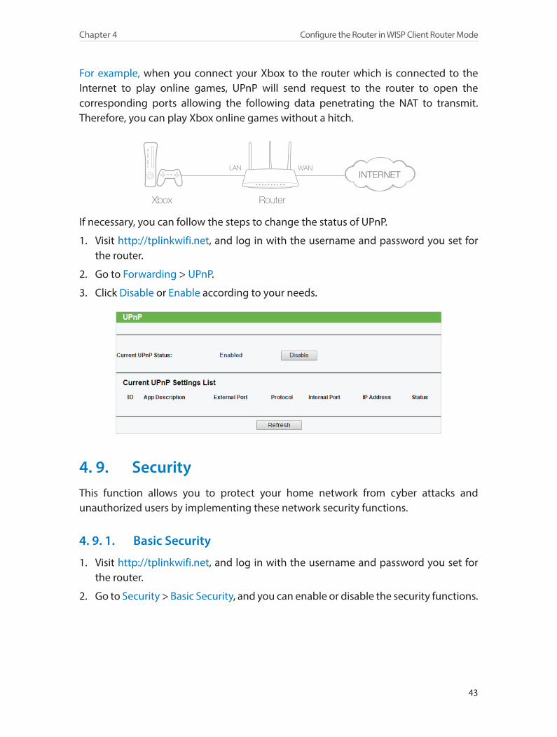
For example, when you connect your Xbox to the router which is connected to the Internet to play online games, UPnP will send request to the router to open the corresponding ports allowing the following data penetrating the NAT to transmit. Therefore, you can play Xbox online games without a hitch.
RouterXbox
LAN WAN
If necessary, you can follow the steps to change the status of UPnP.
1. Visit http://tplinkwifi.net, and log in with the username and password you set for the router.
2. Go to Forwarding > UPnP.
3. Click Disable or Enable according to your needs.
4. 9. SecurityThis function allows you to protect your home network from cyber attacks and unauthorized users by implementing these network security functions.
4. 9. 1. Basic Security
1. Visit http://tplinkwifi.net, and log in with the username and password you set for the router.
2. Go to Security > Basic Security, and you can enable or disable the security functions.
44
Chapter 4 Configure the Router in WISP Client Router Mode
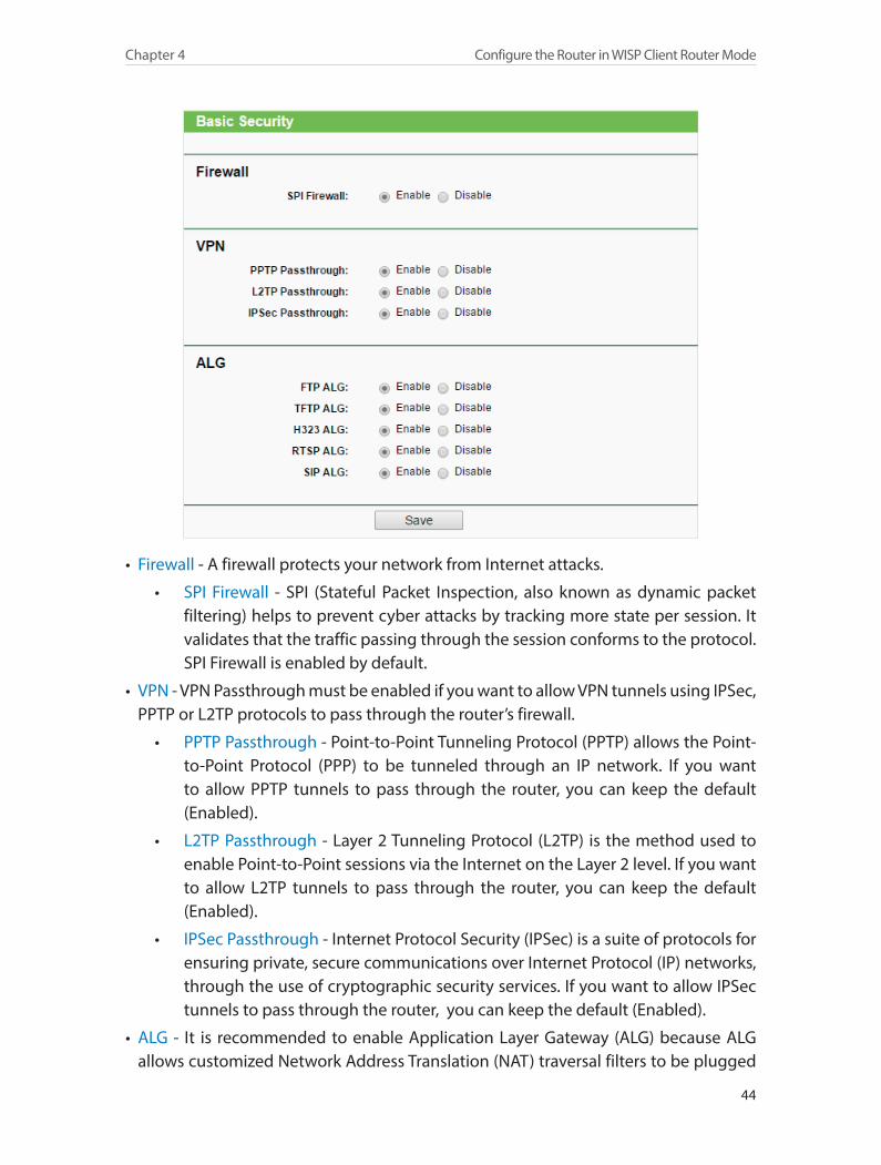
• Firewall - A firewall protects your network from Internet attacks.
• SPI Firewall - SPI (Stateful Packet Inspection, also known as dynamic packet filtering) helps to prevent cyber attacks by tracking more state per session. It validates that the traffic passing through the session conforms to the protocol. SPI Firewall is enabled by default.
• VPN - VPN Passthrough must be enabled if you want to allow VPN tunnels using IPSec, PPTP or L2TP protocols to pass through the router’s firewall.
• PPTP Passthrough - Point-to-Point Tunneling Protocol (PPTP) allows the Point-to-Point Protocol (PPP) to be tunneled through an IP network. If you want to allow PPTP tunnels to pass through the router, you can keep the default (Enabled).
• L2TP Passthrough - Layer 2 Tunneling Protocol (L2TP) is the method used to enable Point-to-Point sessions via the Internet on the Layer 2 level. If you want to allow L2TP tunnels to pass through the router, you can keep the default (Enabled).
• IPSec Passthrough - Internet Protocol Security (IPSec) is a suite of protocols for ensuring private, secure communications over Internet Protocol (IP) networks, through the use of cryptographic security services. If you want to allow IPSec tunnels to pass through the router, you can keep the default (Enabled).
• ALG - It is recommended to enable Application Layer Gateway (ALG) because ALG allows customized Network Address Translation (NAT) traversal filters to be plugged

45
Chapter 4 Configure the Router in WISP Client Router Mode
into the gateway to support address and port translation for certain application layer “control/data” protocols such as FTP, TFTP, H323 etc.
• FTP ALG - To allow FTP clients and servers to transfer data across NAT, keep the default Enable.
• TFTP ALG - To allow TFTP clients and servers to transfer data across NAT, keep the default Enable.
• H323 ALG - To allow Microsoft NetMeeting clients to communicate across NAT, keep the default Enable.
• RTSP ALG - To allow some media player clients to communicate with some streaming media servers across NAT, click Enable.
• SIP ALG - To allow some multimedia clients to communicate across NAT, click Enable.
3. Click Save.
4. 9. 2. Advanced Security
1. Visit http://tplinkwifi.net, and log in with the username and password you set for the router.
2. Go to Security > Advanced Security, and you can protect the router from being attacked by ICMP-Flood, UDP Flood and TCP-SYN Flood.

46
Chapter 4 Configure the Router in WISP Client Router Mode
• Packets Statistics Interval (5~60) - The default value is 10. Select a value between 5 and 60 seconds from the drop-down list. The Packets Statistics Interval value indicates the time section of the packets statistics. The result of the statistics is used for analysis by SYN Flood, UDP Flood and ICMP-Flood.
• DoS Protection - Denial of Service protection. Select Enable or Disable to enable or disable the DoS protection function. Only when it is enabled, will the flood filters be enabled.
Note:Dos Protection will take effect only when the Statistics in System Tool > Statistics is enabled.
• Enable ICMP-FLOOD Attack Filtering -Check the box to enable or disable this function.
• ICMP-FLOOD Packets Threshold (5~3600) - The default value is 50. Enter a value between 5 ~ 3600. When the number of the current ICMP-FLOOD packets is beyond the set value, the router will startup the blocking function immediately.
• Enable UDP-FLOOD Filtering - Check the box to enable or disable this function.
• UDP-FLOOD Packets Threshold (5~3600) - The default value is 500. Enter a value between 5 ~ 3600. When the number of the current UPD-FLOOD packets is beyond the set value, the router will startup the blocking function immediately.
• Enable TCP-SYN-FLOOD Attack Filtering -Check the box to enable or disable this function.
• TCP-SYN-FLOOD Packets Threshold (5~3600) - The default value is 50. Enter a value between 5 ~ 3600. When the number of the current TCP-SYN-FLOOD packets is beyond the set value, the router will startup the blocking function immediately.
• Ignore Ping Packet From WAN Port - The default setting is disabled. If enabled, the ping packet from the Internet cannot access the router.
• Forbid Ping Packet From LAN Port - The default setting is disabled. If enabled, the ping packet from LAN cannot access the router. This function can be used to defend against some viruses.
3. Click Save.
4. Click Blocked DoS Host List to display the DoS host table by blocking.
4. 9. 3. Local Management
1. Visit http://tplinkwifi.net, and log in with the username and password you set for the router.
2. Go to Security > Local Management, and you can block computers on the LAN from accessing the router.

47
Chapter 4 Configure the Router in WISP Client Router Mode
For example, if you want to allow PCs with specific MAC addresses to access the router’s web management page locally from inside the network, please follow the instructions below:
1 ) Select Only the PCs listed can browse the built-in web pages to perform Administrator tasks.
2 ) Enter the MAC address of each PC separately. The format of the MAC address is XX-XX-XX-XX-XX-XX (X is any hexadecimal digit). Only the PCs with the listed MAC addresses can use the password to browse the built-in web pages to perform administrator tasks.
3 ) Click Add, and your PC’s MAC address will also be listed.
4 ) Click Save. Note:
If your PC is blocked but you want to access the router again, press and hold the Reset button to reset the router to the factory defaults.
4. 9. 4. Remote Management
1. Visit http://tplinkwifi.net, and log in with the username and password you set for the router.
2. Go to Security > Remote Management, and you can manage your router from a remote device via the Internet.
48
Chapter 4 Configure the Router in WISP Client Router Mode
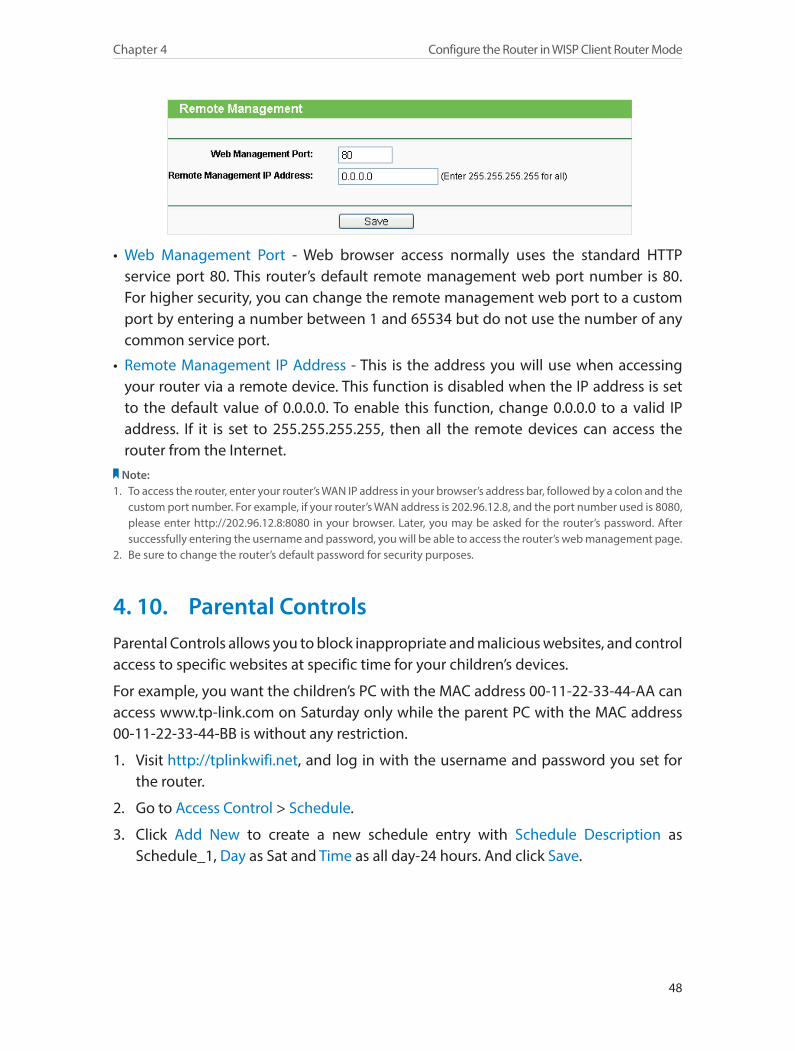
• Web Management Port - Web browser access normally uses the standard HTTP service port 80. This router’s default remote management web port number is 80. For higher security, you can change the remote management web port to a custom port by entering a number between 1 and 65534 but do not use the number of any common service port.
• Remote Management IP Address - This is the address you will use when accessing your router via a remote device. This function is disabled when the IP address is set to the default value of 0.0.0.0. To enable this function, change 0.0.0.0 to a valid IP address. If it is set to 255.255.255.255, then all the remote devices can access the router from the Internet.
Note:1. To access the router, enter your router’s WAN IP address in your browser’s address bar, followed by a colon and the
custom port number. For example, if your router’s WAN address is 202.96.12.8, and the port number used is 8080, please enter http://202.96.12.8:8080 in your browser. Later, you may be asked for the router’s password. After successfully entering the username and password, you will be able to access the router’s web management page.
2. Be sure to change the router’s default password for security purposes.
4. 10. Parental ControlsParental Controls allows you to block inappropriate and malicious websites, and control access to specific websites at specific time for your children’s devices.
For example, you want the children’s PC with the MAC address 00-11-22-33-44-AA can access www.tp-link.com on Saturday only while the parent PC with the MAC address 00-11-22-33-44-BB is without any restriction.
1. Visit http://tplinkwifi.net, and log in with the username and password you set for the router.
2. Go to Access Control > Schedule.
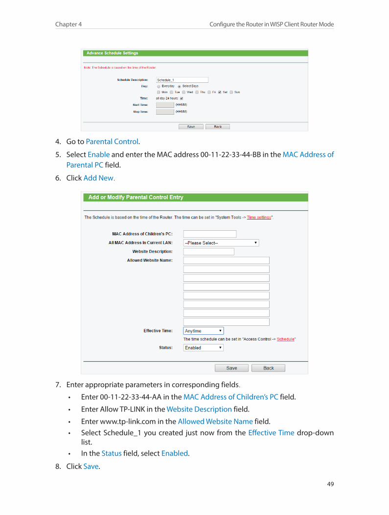
3. Click Add New to create a new schedule entry with Schedule Description as Schedule_1, Day as Sat and Time as all day-24 hours. And click Save.
49
Chapter 4 Configure the Router in WISP Client Router Mode
4. Go to Parental Control.
5. Select Enable and enter the MAC address 00-11-22-33-44-BB in the MAC Address of Parental PC field.
6. Click Add New.
7. Enter appropriate parameters in corresponding fields.
• Enter 00-11-22-33-44-AA in the MAC Address of Children’s PC field.
• Enter Allow TP-LINK in the Website Description field.
• Enter www.tp-link.com in the Allowed Website Name field. • Select Schedule_1 you created just now from the Effective Time drop-down
list. • In the Status field, select Enabled.
8. Click Save.

50
Chapter 4 Configure the Router in WISP Client Router Mode
Then you can go back to the Parental Control Settings page to check the following list.
4. 11. Access ControlAccess Control is used to deny or allow specific client devices to access your network with access time and content restrictions.
Deny or allow specific client devices to access my network with access item and content restrictions.
For example, If you want to restrict the Internet activities of host with MAC address 00-11-22-33-44-AA in the LAN to access www.tp-link.com only, please follow the steps below:
1. Visit http://tplinkwifi.net, and log in with the username and password you set for the router.
2. Go to Access Control > Host and configure the host settings:
1 ) Click Add New.
2 ) Select MAC Address as the mode type. Create a unique description (e.g. host_1) for the host in the Host Description field and enter 00-11-22-33-44-AA in the MAC Address filed.
3 ) Click Save.
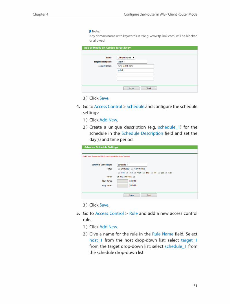
3. Go to Access Control > Target and configure the target settings:
1 ) Click Add New.
2 ) Select Domain Name as the mode type. Create a unique description (e.g. target_1) for the target in the Target Description field and enter the domain name, either the full name or the keywords (for example TP-LINK) in the Domain Name field.
I want to:
How can I do that?
51
Chapter 4 Configure the Router in WISP Client Router Mode
Note:Any domain name with keywords in it (e.g. www.tp-link.com) will be blocked or allowed.
3 ) Click Save.
4. Go to Access Control > Schedule and configure the schedule settings:
1 ) Click Add New.
2 ) Create a unique description (e.g. schedule_1) for the schedule in the Schedule Description field and set the day(s) and time period.
3 ) Click Save.
5. Go to Access Control > Rule and add a new access control rule.
1 ) Click Add New.
2 ) Give a name for the rule in the Rule Name field. Select host_1 from the host drop-down list; select target_1 from the target drop-down list; select schedule_1 from the schedule drop-down list.

52
Chapter 4 Configure the Router in WISP Client Router Mode
3 ) Leave the status as Enabled as click Save.
6. Select Enable Internet Access Control to enable Access Control function.
7. Select Allow the packets specified by any enabled access control policy to pass through the Router as the default filter policy and click Save.
Now only the specific host(s) can visit the target(s) within the scheduled time period.
4. 12. Advanced RoutingStatic Routing is a form of routing that is configured manually by a network administrator or a user by adding entries into a routing table. The manually-configured routing information guides the router in forwarding data packets to the specific destination.
4. 12. 1. Static Routing List
1. Visit http://tplinkwifi.net, and log in with the username and password you set for the router.
2. Go to Advanced Routing > Static Routing.
¾ To add static routing entries:
1. Click Add New.
2. Enter the following information.
Done!
53
Chapter 4 Configure the Router in WISP Client Router Mode
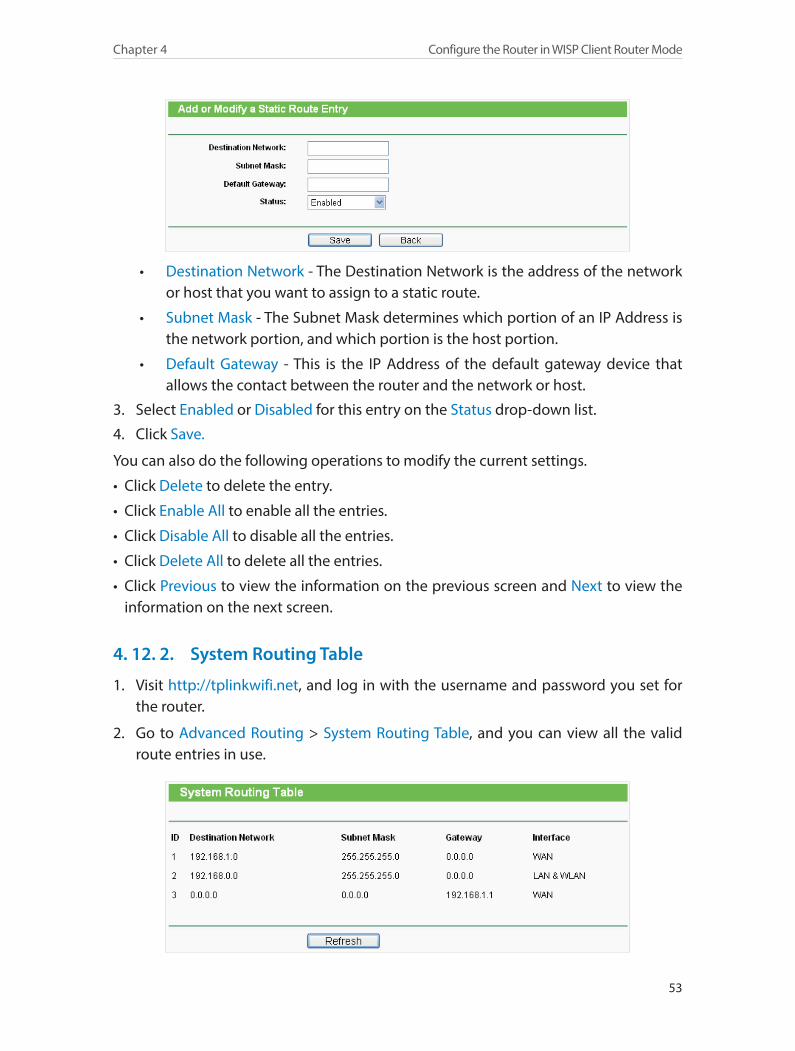
• Destination Network - The Destination Network is the address of the network or host that you want to assign to a static route.
• Subnet Mask - The Subnet Mask determines which portion of an IP Address is the network portion, and which portion is the host portion.
• Default Gateway - This is the IP Address of the default gateway device that allows the contact between the router and the network or host.
3. Select Enabled or Disabled for this entry on the Status drop-down list.
4. Click Save.
You can also do the following operations to modify the current settings.
• Click Delete to delete the entry.
• Click Enable All to enable all the entries.
• Click Disable All to disable all the entries.
• Click Delete All to delete all the entries.
• Click Previous to view the information on the previous screen and Next to view the information on the next screen.
4. 12. 2. System Routing Table
1. Visit http://tplinkwifi.net, and log in with the username and password you set for the router.
2. Go to Advanced Routing > System Routing Table, and you can view all the valid route entries in use.

54
Chapter 4 Configure the Router in WISP Client Router Mode
• Destination Network - The Destination Network is the address of the network or host to which the static route is assigned.
• Subnet Mask - The Subnet Mask determines which portion of an IP address is the network portion, and which portion is the host portion.
• Gateway - This is the IP address of the gateway device that allows contact between the router and the network or host.
• Interface - This interface tells you whether the Destination IP Address is on the LAN & WLAN (internal wired and wireless networks), or the WAN(Internet).
• Click Refresh to refresh the data displayed.
4. 13. Bandwidth Control
4. 13. 1. Control Settings
1. Visit http://tplinkwifi.net, and log in with the username and password you set for the router.
2. Go to Bandwidth Control > Control Settings.
The values you configure for the Egress Bandwidth and Ingress Bandwidth should be less than 100,000Kbps. For optimal control of the bandwidth, please select the right Line Type and consult your ISP for the total egress and ingress bandwidth.
• Enable Bandwidth Control - Check this box so that the Bandwidth Control settings can take effect.
• Line Type - Select the right type for you network connection. If you are not sure, please consult your ISP.
• Egress Bandwidth - The upload speed through the INTERNET port.• Ingress Bandwidth - The download speed through the INTERNET port.
4. 13. 2. Rules List
1. Visit http://tplinkwifi.net, and log in with the username and password you set for the router.
55
Chapter 4 Configure the Router in WISP Client Router Mode
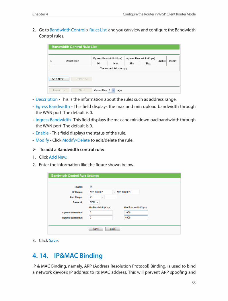
2. Go to Bandwidth Control > Rules List, and you can view and configure the Bandwidth Control rules.
• Description - This is the information about the rules such as address range.
• Egress Bandwidth - This field displays the max and min upload bandwidth through the WAN port. The default is 0.
• Ingress Bandwidth - This field displays the max and min download bandwidth through the WAN port. The default is 0.
• Enable - This field displays the status of the rule.
• Modify - Click Modify/Delete to edit/delete the rule.
¾ To add a Bandwidth control rule:
1. Click Add New.
2. Enter the information like the figure shown below.
3. Click Save.
4. 14. IP&MAC BindingIP & MAC Binding, namely, ARP (Address Resolution Protocol) Binding, is used to bind a network device’s IP address to its MAC address. This will prevent ARP spoofing and
56
Chapter 4 Configure the Router in WISP Client Router Mode
other ARP attacks by denying network access to a device with a matching IP address in the ARP list, but with an unrecognized MAC address.
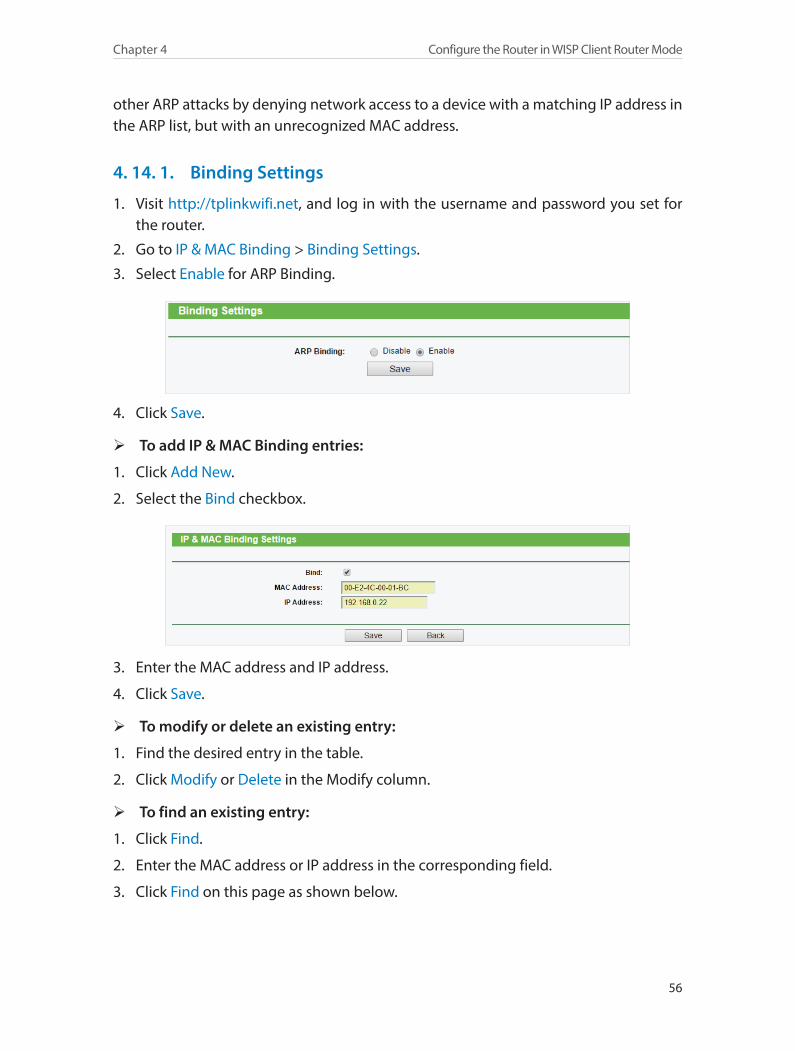
4. 14. 1. Binding Settings
1. Visit http://tplinkwifi.net, and log in with the username and password you set for the router.
2. Go to IP & MAC Binding > Binding Settings.
3. Select Enable for ARP Binding.
4. Click Save.
¾ To add IP & MAC Binding entries:
1. Click Add New.
2. Select the Bind checkbox.
3. Enter the MAC address and IP address.
4. Click Save.
¾ To modify or delete an existing entry:
1. Find the desired entry in the table.
2. Click Modify or Delete in the Modify column.
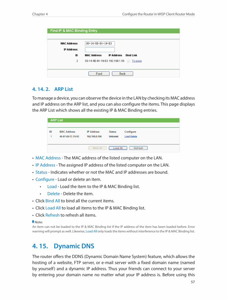
¾ To find an existing entry:
1. Click Find.
2. Enter the MAC address or IP address in the corresponding field.
3. Click Find on this page as shown below.
57
Chapter 4 Configure the Router in WISP Client Router Mode
4. 14. 2. ARP List
To manage a device, you can observe the device in the LAN by checking its MAC address and IP address on the ARP list, and you can also configure the items. This page displays the ARP List which shows all the existing IP & MAC Binding entries.
• MAC Address - The MAC address of the listed computer on the LAN.
• IP Address - The assigned IP address of the listed computer on the LAN.
• Status - Indicates whether or not the MAC and IP addresses are bound.
• Configure - Load or delete an item.
• Load - Load the item to the IP & MAC Binding list.
• Delete - Delete the item.
• Click Bind All to bind all the current items.
• Click Load All to load all items to the IP & MAC Binding list.
• Click Refresh to refresh all items.Note:
An item can not be loaded to the IP & MAC Binding list if the IP address of the item has been loaded before. Error warning will prompt as well. Likewise, Load All only loads the items without interference to the IP & MAC Binding list.
4. 15. Dynamic DNSThe router offers the DDNS (Dynamic Domain Name System) feature, which allows the hosting of a website, FTP server, or e-mail server with a fixed domain name (named by yourself ) and a dynamic IP address. Thus your friends can connect to your server by entering your domain name no matter what your IP address is. Before using this
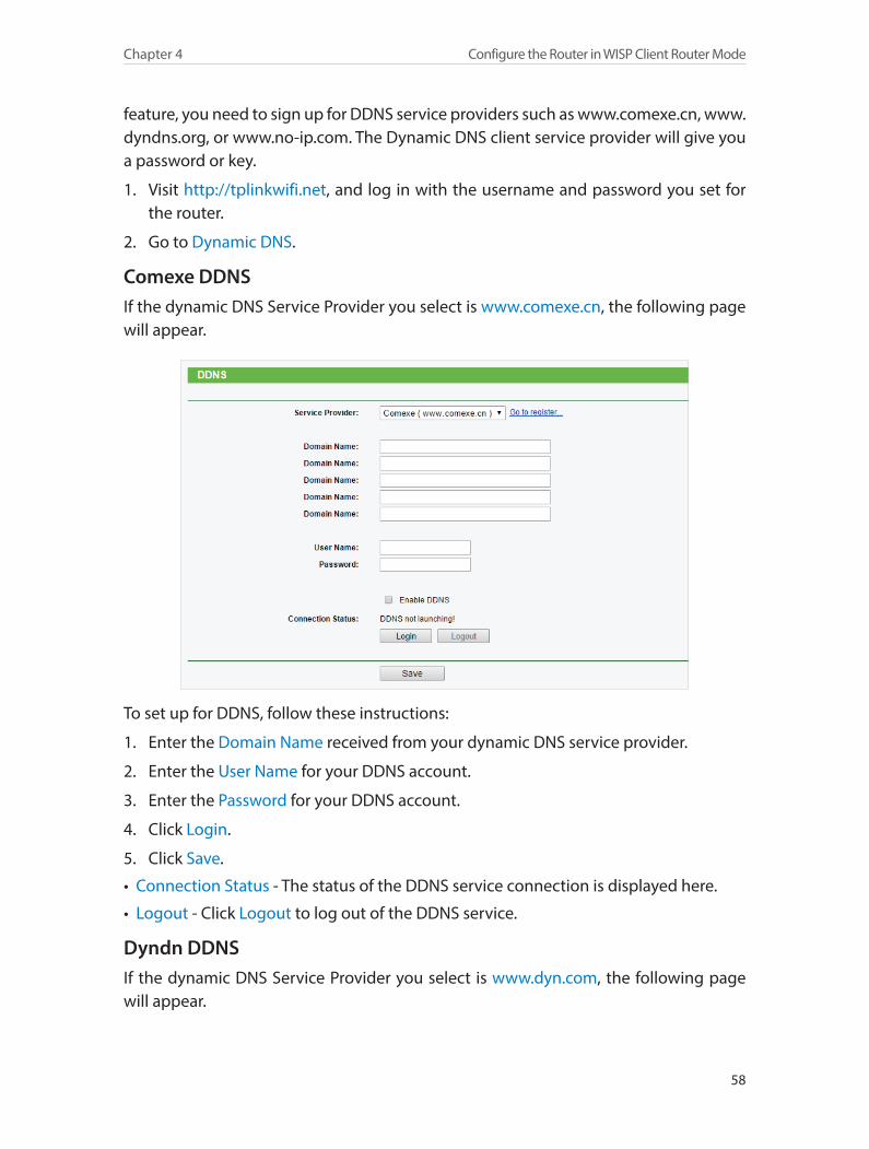
58
Chapter 4 Configure the Router in WISP Client Router Mode
feature, you need to sign up for DDNS service providers such as www.comexe.cn, www.dyndns.org, or www.no-ip.com. The Dynamic DNS client service provider will give you a password or key.
1. Visit http://tplinkwifi.net, and log in with the username and password you set for the router.
2. Go to Dynamic DNS.
Comexe DDNSIf the dynamic DNS Service Provider you select is www.comexe.cn, the following page will appear.
To set up for DDNS, follow these instructions:
1. Enter the Domain Name received from your dynamic DNS service provider.
2. Enter the User Name for your DDNS account.
3. Enter the Password for your DDNS account.
4. Click Login.
5. Click Save.
• Connection Status - The status of the DDNS service connection is displayed here.
• Logout - Click Logout to log out of the DDNS service.
Dyndn DDNSIf the dynamic DNS Service Provider you select is www.dyn.com, the following page will appear.
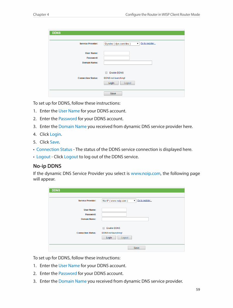
59
Chapter 4 Configure the Router in WISP Client Router Mode
To set up for DDNS, follow these instructions:
1. Enter the User Name for your DDNS account.
2. Enter the Password for your DDNS account.
3. Enter the Domain Name you received from dynamic DNS service provider here.
4. Click Login.
5. Click Save.
• Connection Status - The status of the DDNS service connection is displayed here.
• Logout - Click Logout to log out of the DDNS service.
No-ip DDNSIf the dynamic DNS Service Provider you select is www.noip.com, the following page will appear.
To set up for DDNS, follow these instructions:
1. Enter the User Name for your DDNS account.
2. Enter the Password for your DDNS account.
3. Enter the Domain Name you received from dynamic DNS service provider.
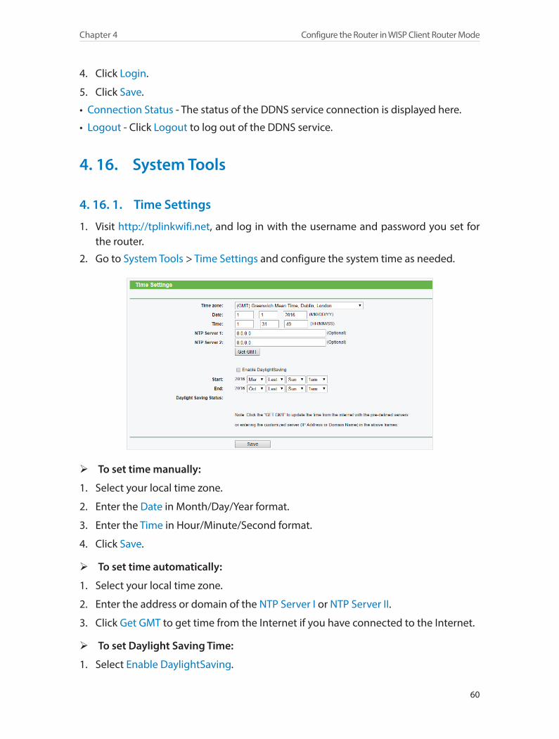
60
Chapter 4 Configure the Router in WISP Client Router Mode
4. Click Login.
5. Click Save.
• Connection Status - The status of the DDNS service connection is displayed here.
• Logout - Click Logout to log out of the DDNS service.
4. 16. System Tools
4. 16. 1. Time Settings
1. Visit http://tplinkwifi.net, and log in with the username and password you set for the router.
2. Go to System Tools > Time Settings and configure the system time as needed.
¾ To set time manually:
1. Select your local time zone.
2. Enter the Date in Month/Day/Year format.
3. Enter the Time in Hour/Minute/Second format.
4. Click Save.
¾ To set time automatically:
1. Select your local time zone.
2. Enter the address or domain of the NTP Server I or NTP Server II.
3. Click Get GMT to get time from the Internet if you have connected to the Internet.
¾ To set Daylight Saving Time:
1. Select Enable DaylightSaving.
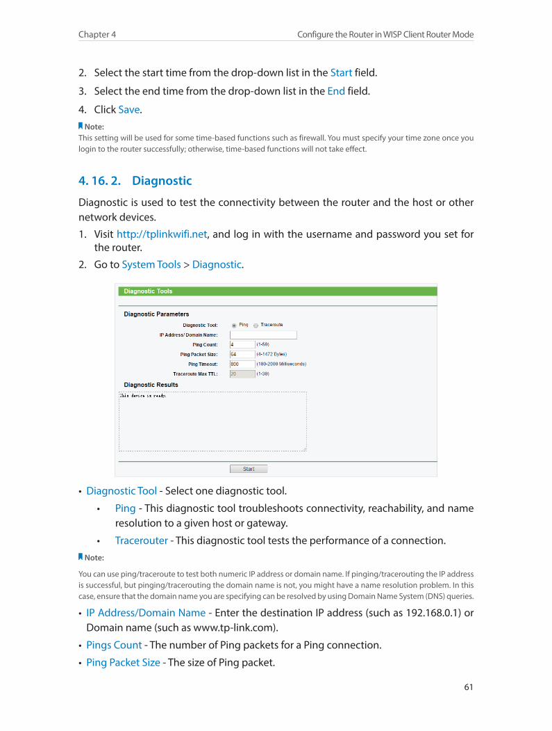
61
Chapter 4 Configure the Router in WISP Client Router Mode
2. Select the start time from the drop-down list in the Start field.
3. Select the end time from the drop-down list in the End field.
4. Click Save.Note:
This setting will be used for some time-based functions such as firewall. You must specify your time zone once you login to the router successfully; otherwise, time-based functions will not take effect.
4. 16. 2. Diagnostic
Diagnostic is used to test the connectivity between the router and the host or other network devices.
1. Visit http://tplinkwifi.net, and log in with the username and password you set for the router.
2. Go to System Tools > Diagnostic.
• Diagnostic Tool - Select one diagnostic tool.
• Ping - This diagnostic tool troubleshoots connectivity, reachability, and name resolution to a given host or gateway.
• Tracerouter - This diagnostic tool tests the performance of a connection.Note:
You can use ping/traceroute to test both numeric IP address or domain name. If pinging/tracerouting the IP address is successful, but pinging/tracerouting the domain name is not, you might have a name resolution problem. In this case, ensure that the domain name you are specifying can be resolved by using Domain Name System (DNS) queries.
• IP Address/Domain Name - Enter the destination IP address (such as 192.168.0.1) or Domain name (such as www.tp-link.com).
• Pings Count - The number of Ping packets for a Ping connection.
• Ping Packet Size - The size of Ping packet.
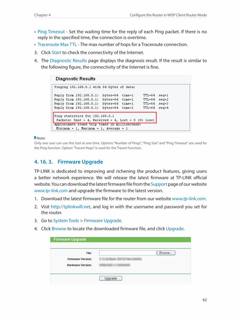
62
Chapter 4 Configure the Router in WISP Client Router Mode
• Ping Timeout - Set the waiting time for the reply of each Ping packet. If there is no reply in the specified time, the connection is overtime.
• Traceroute Max TTL - The max number of hops for a Traceroute connection.
3. Click Start to check the connectivity of the Internet.
4. The Diagnostic Results page displays the diagnosis result. If the result is similar to the following figure, the connectivity of the Internet is fine.
Note: Only one user can use this tool at one time. Options “Number of Pings”, “Ping Size” and “Ping Timeout” are used for the Ping function. Option “Tracert Hops” is used for the Tracert function.
4. 16. 3. Firmware Upgrade
TP-LINK is dedicated to improving and richening the product features, giving users a better network experience. We will release the latest firmware at TP-LINK official website. You can download the latest firmware file from the Support page of our website www.tp-link.com and upgrade the firmware to the latest version.
1. Download the latest firmware file for the router from our website www.tp-link.com.
2. Visit http://tplinkwifi.net, and log in with the username and password you set for the router.
3. Go to System Tools > Firmware Upgrade.
4. Click Browse to locate the downloaded firmware file, and click Upgrade.
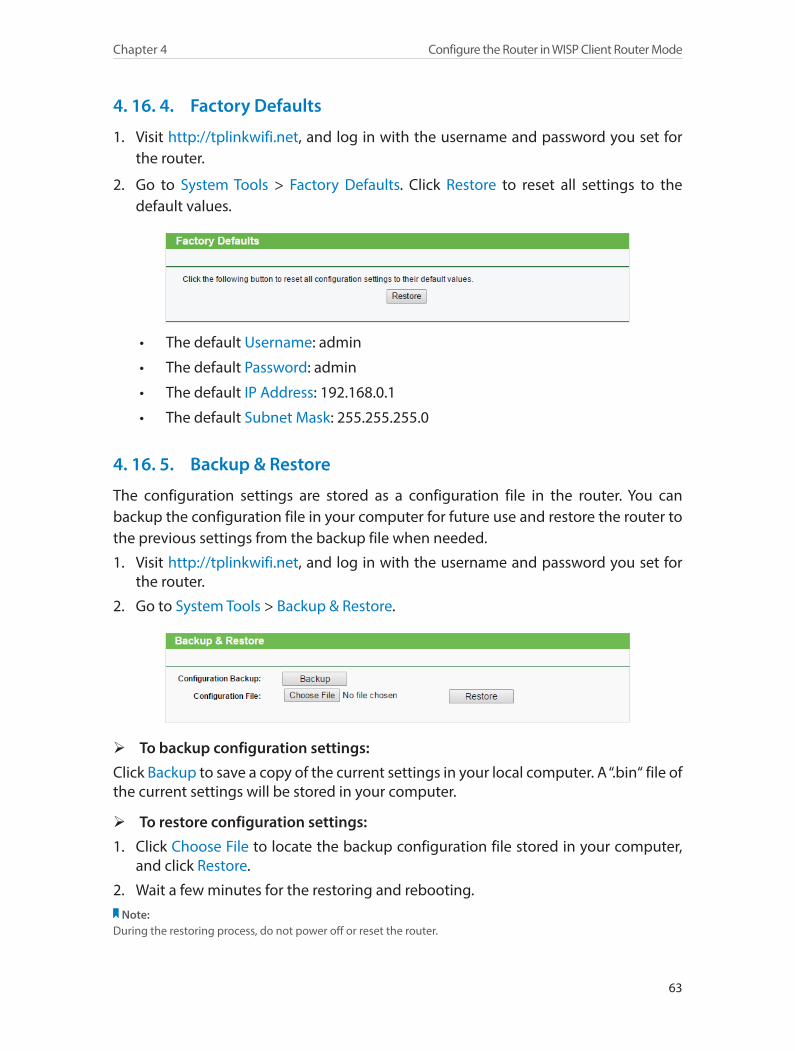
63
Chapter 4 Configure the Router in WISP Client Router Mode
4. 16. 4. Factory Defaults
1. Visit http://tplinkwifi.net, and log in with the username and password you set for the router.
2. Go to System Tools > Factory Defaults. Click Restore to reset all settings to the default values.
• The default Username: admin
• The default Password: admin
• The default IP Address: 192.168.0.1
• The default Subnet Mask: 255.255.255.0
4. 16. 5. Backup & Restore
The configuration settings are stored as a configuration file in the router. You can backup the configuration file in your computer for future use and restore the router to the previous settings from the backup file when needed.
1. Visit http://tplinkwifi.net, and log in with the username and password you set for the router.
2. Go to System Tools > Backup & Restore.
¾ To backup configuration settings:
Click Backup to save a copy of the current settings in your local computer. A “.bin“ file of the current settings will be stored in your computer.
¾ To restore configuration settings:
1. Click Choose File to locate the backup configuration file stored in your computer, and click Restore.
2. Wait a few minutes for the restoring and rebooting.Note:
During the restoring process, do not power off or reset the router.
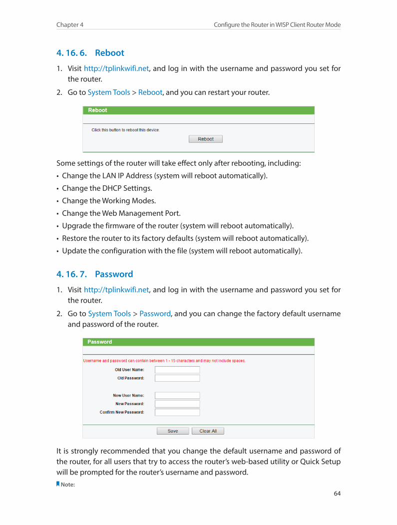
64
Chapter 4 Configure the Router in WISP Client Router Mode
4. 16. 6. Reboot
1. Visit http://tplinkwifi.net, and log in with the username and password you set for the router.
2. Go to System Tools > Reboot, and you can restart your router.
Some settings of the router will take effect only after rebooting, including:
• Change the LAN IP Address (system will reboot automatically).
• Change the DHCP Settings.
• Change the Working Modes.
• Change the Web Management Port.
• Upgrade the firmware of the router (system will reboot automatically).
• Restore the router to its factory defaults (system will reboot automatically).
• Update the configuration with the file (system will reboot automatically).
4. 16. 7. Password
1. Visit http://tplinkwifi.net, and log in with the username and password you set for the router.
2. Go to System Tools > Password, and you can change the factory default username and password of the router.
It is strongly recommended that you change the default username and password of the router, for all users that try to access the router’s web-based utility or Quick Setup will be prompted for the router’s username and password.
Note:
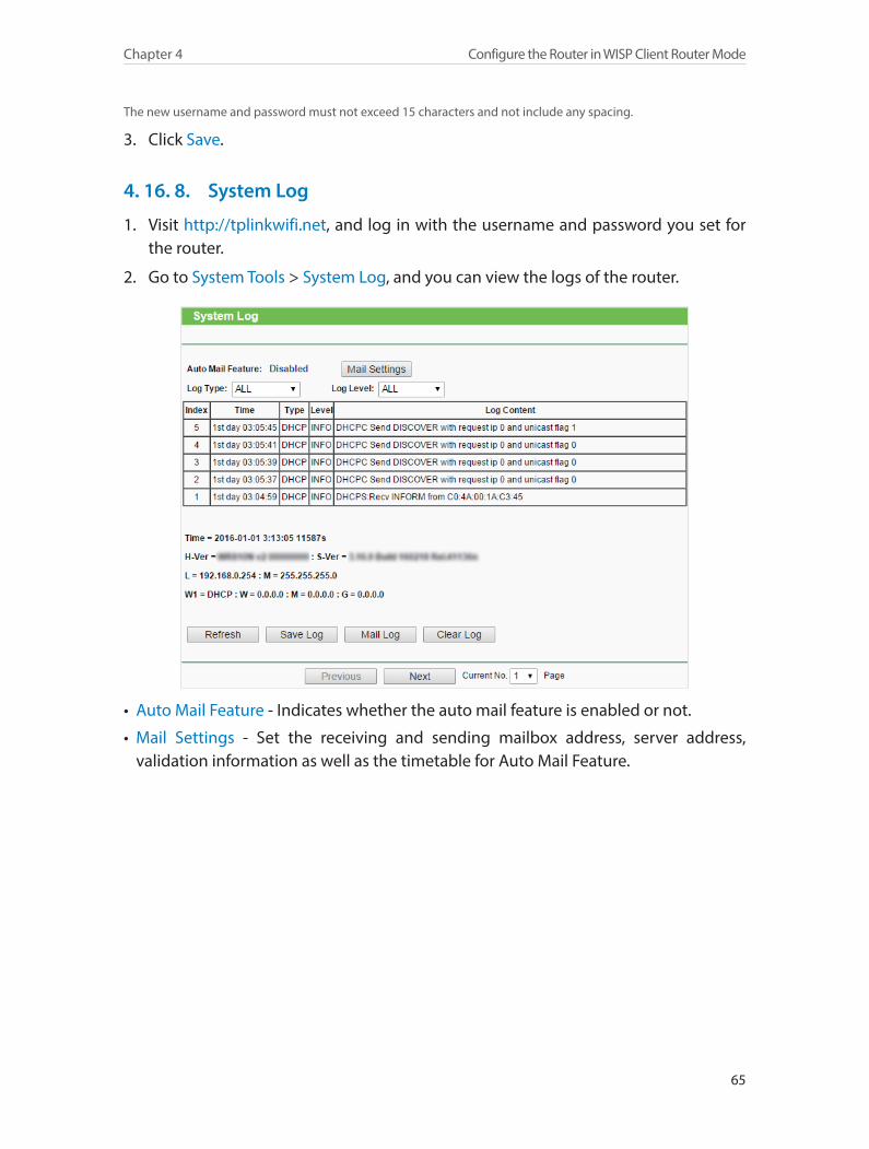
65
Chapter 4 Configure the Router in WISP Client Router Mode
The new username and password must not exceed 15 characters and not include any spacing.
3. Click Save.
4. 16. 8. System Log
1. Visit http://tplinkwifi.net, and log in with the username and password you set for the router.
2. Go to System Tools > System Log, and you can view the logs of the router.
• Auto Mail Feature - Indicates whether the auto mail feature is enabled or not.
• Mail Settings - Set the receiving and sending mailbox address, server address, validation information as well as the timetable for Auto Mail Feature.
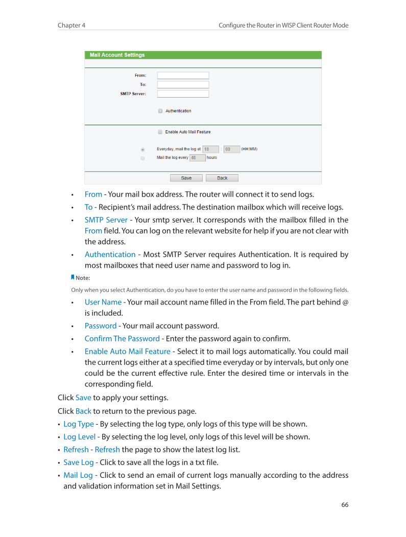
66
Chapter 4 Configure the Router in WISP Client Router Mode
• From - Your mail box address. The router will connect it to send logs.
• To - Recipient’s mail address. The destination mailbox which will receive logs.
• SMTP Server - Your smtp server. It corresponds with the mailbox filled in the From field. You can log on the relevant website for help if you are not clear with the address.
• Authentication - Most SMTP Server requires Authentication. It is required by most mailboxes that need user name and password to log in.
Note:
Only when you select Authentication, do you have to enter the user name and password in the following fields.
• User Name - Your mail account name filled in the From field. The part behind @ is included.
• Password - Your mail account password.
• Confirm The Password - Enter the password again to confirm.
• Enable Auto Mail Feature - Select it to mail logs automatically. You could mail the current logs either at a specified time everyday or by intervals, but only one could be the current effective rule. Enter the desired time or intervals in the corresponding field.
Click Save to apply your settings.
Click Back to return to the previous page.
• Log Type - By selecting the log type, only logs of this type will be shown.
• Log Level - By selecting the log level, only logs of this level will be shown.
• Refresh - Refresh the page to show the latest log list.
• Save Log - Click to save all the logs in a txt file.
• Mail Log - Click to send an email of current logs manually according to the address and validation information set in Mail Settings.
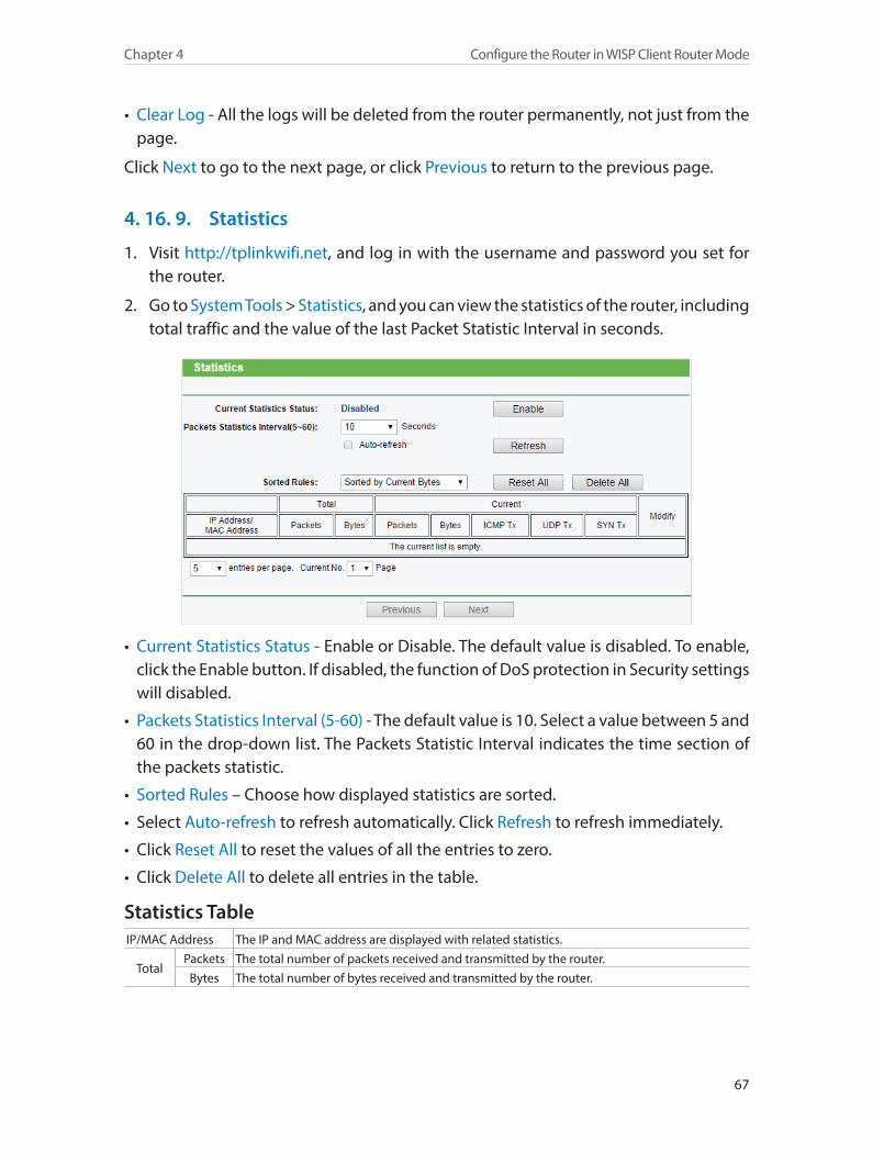
67
Chapter 4 Configure the Router in WISP Client Router Mode
• Clear Log - All the logs will be deleted from the router permanently, not just from the page.
Click Next to go to the next page, or click Previous to return to the previous page.
4. 16. 9. Statistics
1. Visit http://tplinkwifi.net, and log in with the username and password you set for the router.
2. Go to System Tools > Statistics, and you can view the statistics of the router, including total traffic and the value of the last Packet Statistic Interval in seconds.
• Current Statistics Status - Enable or Disable. The default value is disabled. To enable, click the Enable button. If disabled, the function of DoS protection in Security settings will disabled.
• Packets Statistics Interval (5-60) - The default value is 10. Select a value between 5 and 60 in the drop-down list. The Packets Statistic Interval indicates the time section of the packets statistic.
• Sorted Rules – Choose how displayed statistics are sorted.
• Select Auto-refresh to refresh automatically. Click Refresh to refresh immediately.
• Click Reset All to reset the values of all the entries to zero.
• Click Delete All to delete all entries in the table.
Statistics TableIP/MAC Address The IP and MAC address are displayed with related statistics.
TotalPackets The total number of packets received and transmitted by the router.
Bytes The total number of bytes received and transmitted by the router.
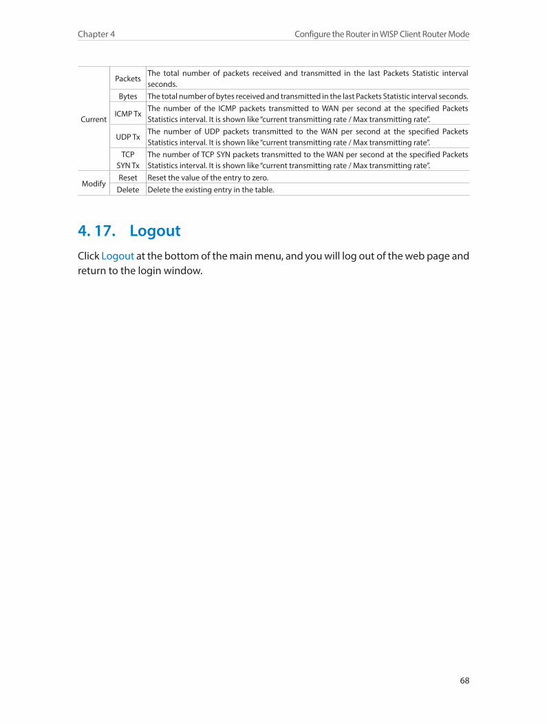
68
Chapter 4 Configure the Router in WISP Client Router Mode
Current
PacketsThe total number of packets received and transmitted in the last Packets Statistic interval seconds.
Bytes The total number of bytes received and transmitted in the last Packets Statistic interval seconds.
ICMP TxThe number of the ICMP packets transmitted to WAN per second at the specified Packets Statistics interval. It is shown like “current transmitting rate / Max transmitting rate”.
UDP TxThe number of UDP packets transmitted to the WAN per second at the specified Packets Statistics interval. It is shown like “current transmitting rate / Max transmitting rate”.
TCP SYN Tx
The number of TCP SYN packets transmitted to the WAN per second at the specified Packets Statistics interval. It is shown like “current transmitting rate / Max transmitting rate”.
ModifyReset Reset the value of the entry to zero.
Delete Delete the existing entry in the table.
4. 17. LogoutClick Logout at the bottom of the main menu, and you will log out of the web page and return to the login window.
Chapter 5
Configure the Router in Standard Wireless Router ModeThis chapter presents how to configure the various features of the router working as a Standard Wireless Router.
This chapter contains the following sections:
• Status
• WPS
• Working Mode
• Network
• Wireless
• Guest Network
• DHCP
• Forwarding
• Security
• Parental Controls
• Access Control
• Advanced Routing
• Bandwidth Control
• IP&MAC Binding
• Dynamic DNS
• IPv6 Support
• System Tools
• Logout
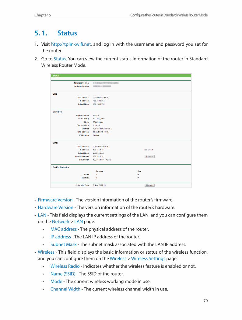
70
Chapter 5 Configure the Router in Standard Wireless Router Mode
5. 1. Status1. Visit http://tplinkwifi.net, and log in with the username and password you set for
the router.
2. Go to Status. You can view the current status information of the router in Standard Wireless Router Mode.
• Firmware Version - The version information of the router’s firmware.
• Hardware Version - The version information of the router’s hardware.
• LAN - This field displays the current settings of the LAN, and you can configure them on the Network > LAN page.
• MAC address - The physical address of the router.
• IP address - The LAN IP address of the router.
• Subnet Mask - The subnet mask associated with the LAN IP address.
• Wireless - This field displays the basic information or status of the wireless function, and you can configure them on the Wireless > Wireless Settings page.
• Wireless Radio - Indicates whether the wireless feature is enabled or not.
• Name (SSID) - The SSID of the router.
• Mode - The current wireless working mode in use.
• Channel Width - The current wireless channel width in use.
71
Chapter 5 Configure the Router in Standard Wireless Router Mode
• Channel - The current wireless channel in use.
• MAC Address - The physical address of the router.
• WDS Status - The status of WDS connection.
• WAN - This field displays the current settings of the WAN, and you can configure them on the Network > WAN page.
• MAC Address - The physical address of the WAN port.
• IP Address - The current WAN (Internet) IP Address. This field will be blank or 0.0.0.0 if the IP Address is assigned dynamically and there is no Internet connection.
• Subnet Mask - The subnet mask associated with the WAN IP Address.
• Default Gateway - The Gateway currently used is shown here. When you use Dynamic IP as the WAN connection type, click Renew or Release here to obtain new IP parameters dynamically from the ISP or release them.
• DNS Server - The IP addresses of DNS (Domain Name System) server.
• Traffic Statistics - The router’s traffic statistics.
• Received (Bytes) - Traffic in bytes received from the WAN port.
• Received (Packets) - Traffic in packets received from the WAN port.
• Sent (Bytes) - Traffic in bytes sent out from the WAN port.
• Sent (Packets) - Traffic in packets sent out from the WAN port.
• System Up Time - The length of the time since the router was last powered on or reset.
Click Refresh to get the latest status and settings of the router.
5. 2. WPSWPS (Wi-Fi Protected Setup) can help you to quickly and securely connect to a network. This section will guide you to add a new wireless device to your router’s network quickly via WPS.
Note:The WPS function cannot be configured if the wireless function of the router is disabled. Please make sure the wireless function is enabled before configuration.
1. Visit http://tplinkwifi.net, and log in with the username and password you set for the router.
2. Go to WPS.
3. Follow one of the following three methods to connect your client device to the router’s Wi-Fi network.
Method ONE: Press the WPS Button on Your Client Device1. Keep the WPS Status as Enabled and click Add Device.
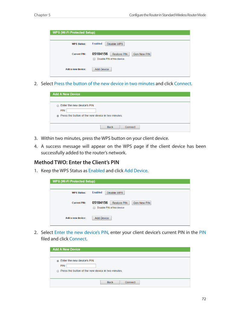
72
Chapter 5 Configure the Router in Standard Wireless Router Mode
2. Select Press the button of the new device in two minutes and click Connect.
3. Within two minutes, press the WPS button on your client device.
4. A success message will appear on the WPS page if the client device has been successfully added to the router’s network.
Method TWO: Enter the Client’s PIN1. Keep the WPS Status as Enabled and click Add Device.
2. Select Enter the new device’s PIN, enter your client device’s current PIN in the PIN filed and click Connect.
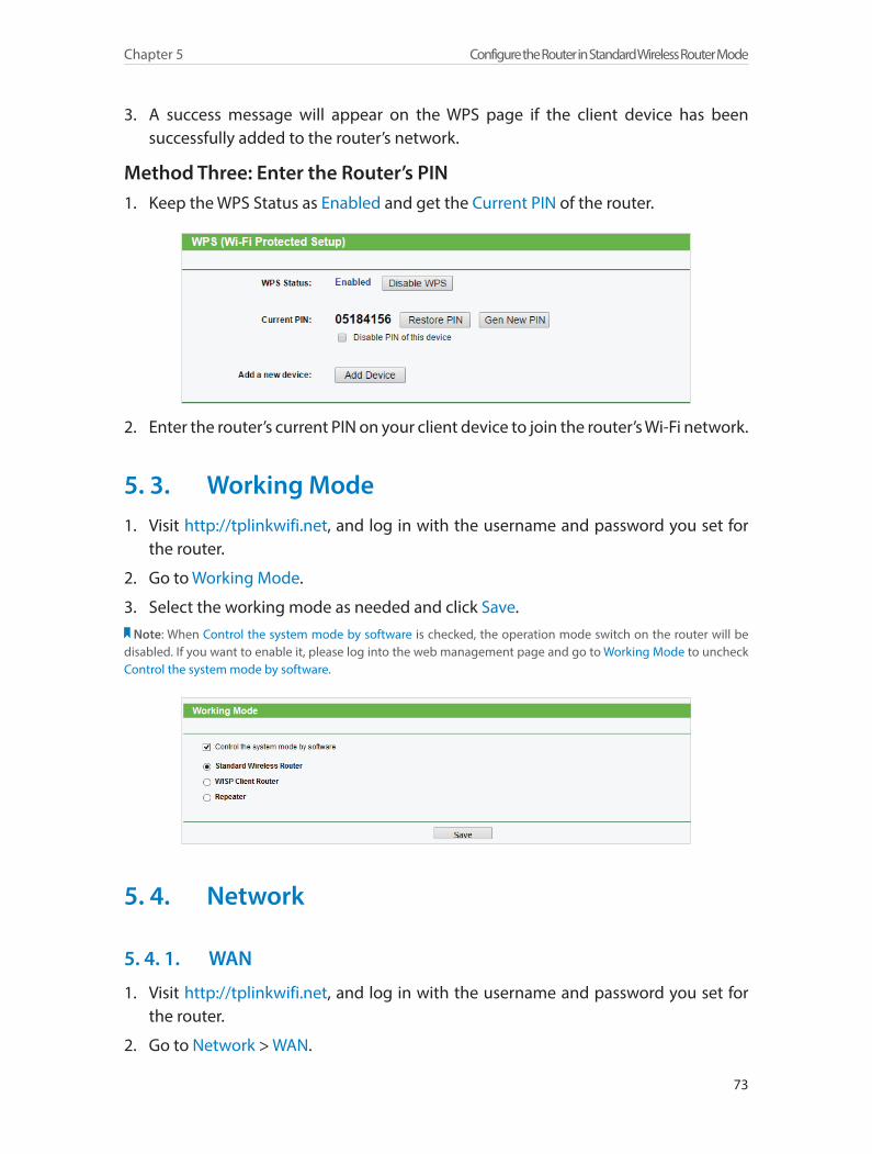
73
Chapter 5 Configure the Router in Standard Wireless Router Mode
3. A success message will appear on the WPS page if the client device has been successfully added to the router’s network.
Method Three: Enter the Router’s PIN1. Keep the WPS Status as Enabled and get the Current PIN of the router.
2. Enter the router’s current PIN on your client device to join the router’s Wi-Fi network.
5. 3. Working Mode1. Visit http://tplinkwifi.net, and log in with the username and password you set for
the router.
2. Go to Working Mode.
3. Select the working mode as needed and click Save.Note: When Control the system mode by software is checked, the operation mode switch on the router will be
disabled. If you want to enable it, please log into the web management page and go to Working Mode to uncheck Control the system mode by software.
5. 4. Network
5. 4. 1. WAN
1. Visit http://tplinkwifi.net, and log in with the username and password you set for the router.
2. Go to Network > WAN.
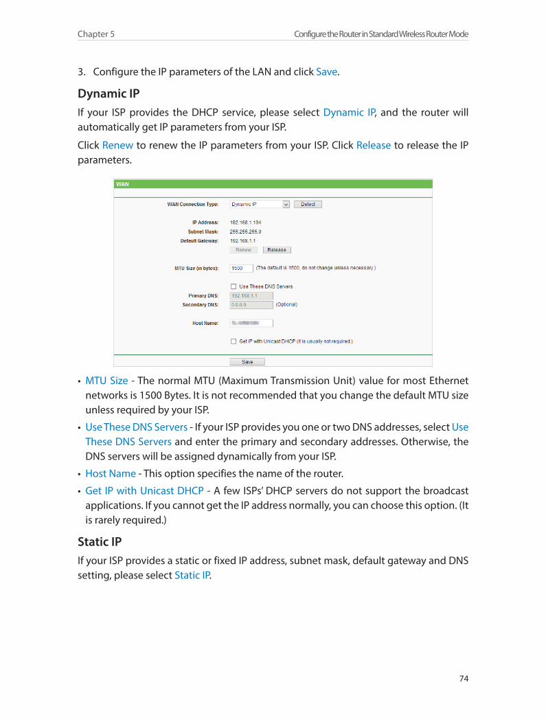
74
Chapter 5 Configure the Router in Standard Wireless Router Mode
3. Configure the IP parameters of the LAN and click Save.
Dynamic IPIf your ISP provides the DHCP service, please select Dynamic IP, and the router will automatically get IP parameters from your ISP.
Click Renew to renew the IP parameters from your ISP. Click Release to release the IP parameters.
• MTU Size - The normal MTU (Maximum Transmission Unit) value for most Ethernet networks is 1500 Bytes. It is not recommended that you change the default MTU size unless required by your ISP.
• Use These DNS Servers - If your ISP provides you one or two DNS addresses, select Use These DNS Servers and enter the primary and secondary addresses. Otherwise, the DNS servers will be assigned dynamically from your ISP.
• Host Name - This option specifies the name of the router.
• Get IP with Unicast DHCP - A few ISPs’ DHCP servers do not support the broadcast applications. If you cannot get the IP address normally, you can choose this option. (It is rarely required.)
Static IPIf your ISP provides a static or fixed IP address, subnet mask, default gateway and DNS setting, please select Static IP.
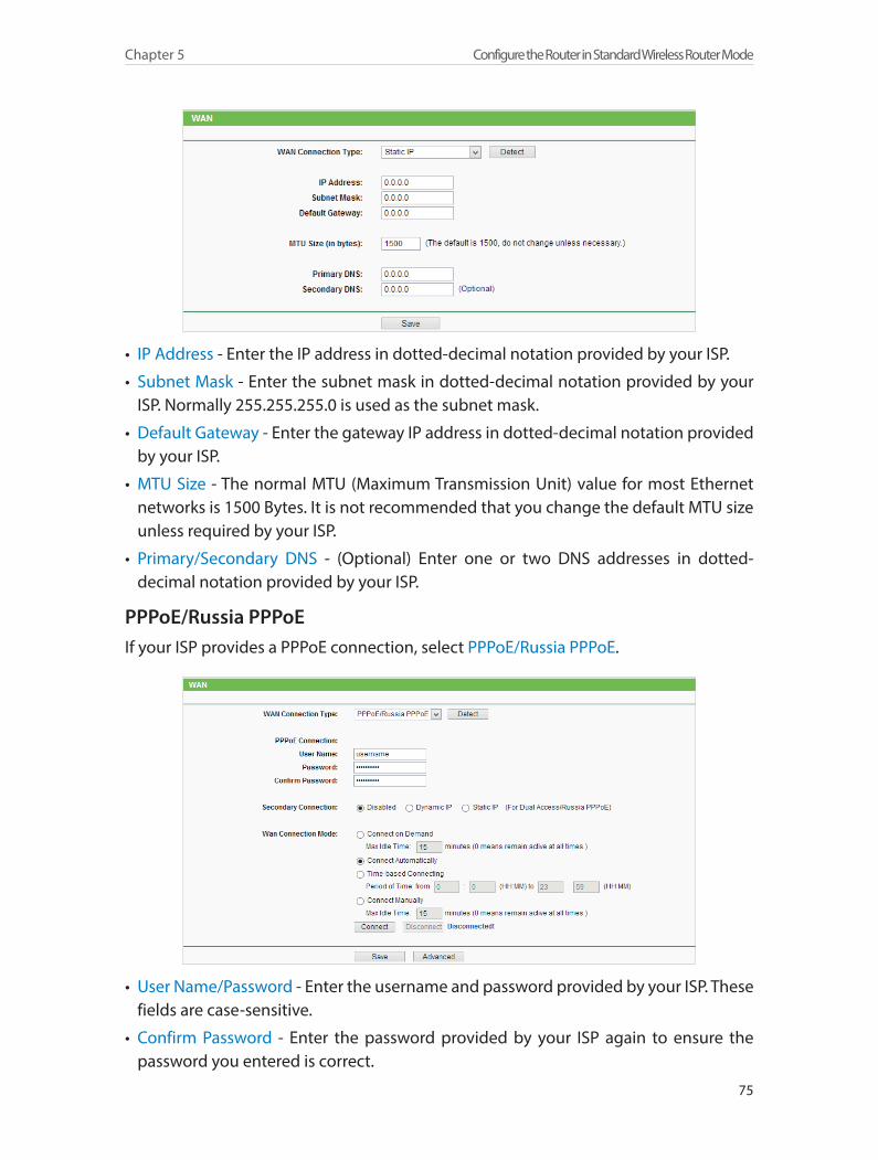
75
Chapter 5 Configure the Router in Standard Wireless Router Mode
• IP Address - Enter the IP address in dotted-decimal notation provided by your ISP.
• Subnet Mask - Enter the subnet mask in dotted-decimal notation provided by your ISP. Normally 255.255.255.0 is used as the subnet mask.
• Default Gateway - Enter the gateway IP address in dotted-decimal notation provided by your ISP.
• MTU Size - The normal MTU (Maximum Transmission Unit) value for most Ethernet networks is 1500 Bytes. It is not recommended that you change the default MTU size unless required by your ISP.
• Primary/Secondary DNS - (Optional) Enter one or two DNS addresses in dotted-decimal notation provided by your ISP.
PPPoE/Russia PPPoEIf your ISP provides a PPPoE connection, select PPPoE/Russia PPPoE.
• User Name/Password - Enter the username and password provided by your ISP. These fields are case-sensitive.
• Confirm Password - Enter the password provided by your ISP again to ensure the password you entered is correct.
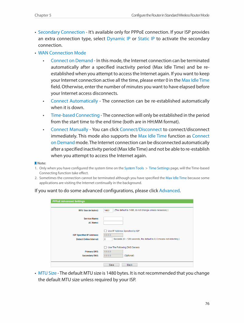
76
Chapter 5 Configure the Router in Standard Wireless Router Mode
• Secondary Connection - It’s available only for PPPoE connection. If your ISP provides an extra connection type, select Dynamic IP or Static IP to activate the secondary connection.
• WAN Connection Mode
• Connect on Demand - In this mode, the Internet connection can be terminated automatically after a specified inactivity period (Max Idle Time) and be re-established when you attempt to access the Internet again. If you want to keep your Internet connection active all the time, please enter 0 in the Max Idle Time field. Otherwise, enter the number of minutes you want to have elapsed before your Internet access disconnects.
• Connect Automatically - The connection can be re-established automatically when it is down.
• Time-based Connecting - The connection will only be established in the period from the start time to the end time (both are in HH:MM format).
• Connect Manually - You can click Connect/Disconnect to connect/disconnect immediately. This mode also supports the Max Idle Time function as Connect on Demand mode. The Internet connection can be disconnected automatically after a specified inactivity period (Max Idle Time) and not be able to re-establish when you attempt to access the Internet again.
Note:1. Only when you have configured the system time on the System Tools > Time Settings page, will the Time-based
Connecting function take effect.2. Sometimes the connection cannot be terminated although you have specified the Max Idle Time because some
applications are visiting the Internet continually in the background.
If you want to do some advanced configurations, please click Advanced.
• MTU Size - The default MTU size is 1480 bytes. It is not recommended that you change the default MTU size unless required by your ISP.
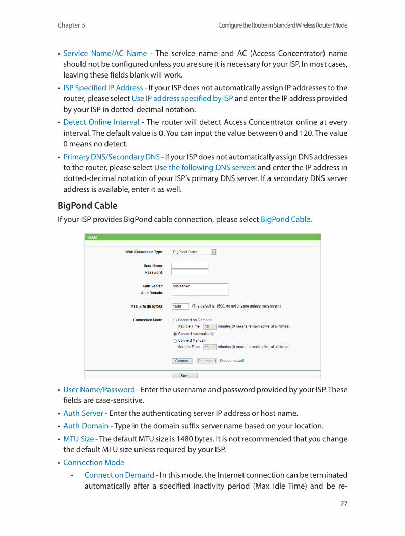
77
Chapter 5 Configure the Router in Standard Wireless Router Mode
• Service Name/AC Name - The service name and AC (Access Concentrator) name should not be configured unless you are sure it is necessary for your ISP. In most cases, leaving these fields blank will work.
• ISP Specified IP Address - If your ISP does not automatically assign IP addresses to the router, please select Use IP address specified by ISP and enter the IP address provided by your ISP in dotted-decimal notation.
• Detect Online Interval - The router will detect Access Concentrator online at every interval. The default value is 0. You can input the value between 0 and 120. The value 0 means no detect.
• Primary DNS/Secondary DNS - If your ISP does not automatically assign DNS addresses to the router, please select Use the following DNS servers and enter the IP address in dotted-decimal notation of your ISP’s primary DNS server. If a secondary DNS server address is available, enter it as well.
BigPond CableIf your ISP provides BigPond cable connection, please select BigPond Cable.
• User Name/Password - Enter the username and password provided by your ISP. These fields are case-sensitive.
• Auth Server - Enter the authenticating server IP address or host name.
• Auth Domain - Type in the domain suffix server name based on your location.
• MTU Size - The default MTU size is 1480 bytes. It is not recommended that you change the default MTU size unless required by your ISP.
• Connection Mode
• Connect on Demand - In this mode, the Internet connection can be terminated automatically after a specified inactivity period (Max Idle Time) and be re-
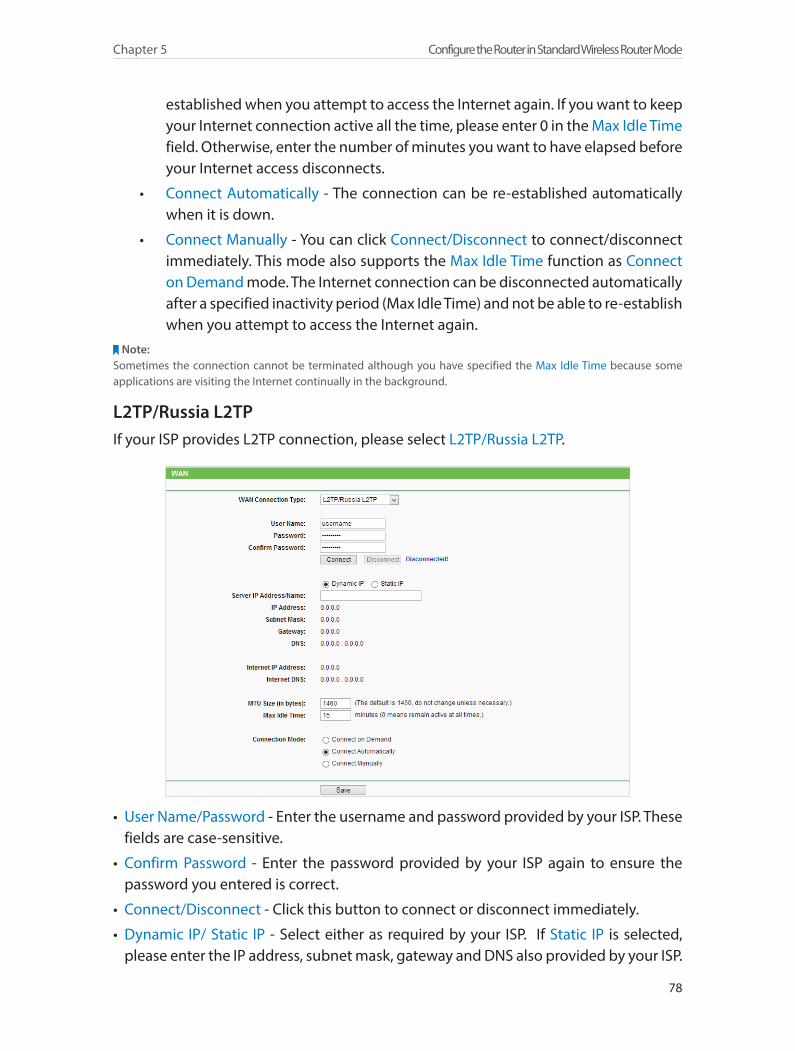
78
Chapter 5 Configure the Router in Standard Wireless Router Mode
established when you attempt to access the Internet again. If you want to keep your Internet connection active all the time, please enter 0 in the Max Idle Time field. Otherwise, enter the number of minutes you want to have elapsed before your Internet access disconnects.
• Connect Automatically - The connection can be re-established automatically when it is down.
• Connect Manually - You can click Connect/Disconnect to connect/disconnect immediately. This mode also supports the Max Idle Time function as Connect on Demand mode. The Internet connection can be disconnected automatically after a specified inactivity period (Max Idle Time) and not be able to re-establish when you attempt to access the Internet again.
Note:Sometimes the connection cannot be terminated although you have specified the Max Idle Time because some applications are visiting the Internet continually in the background.
L2TP/Russia L2TPIf your ISP provides L2TP connection, please select L2TP/Russia L2TP.
• User Name/Password - Enter the username and password provided by your ISP. These fields are case-sensitive.
• Confirm Password - Enter the password provided by your ISP again to ensure the password you entered is correct.
• Connect/Disconnect - Click this button to connect or disconnect immediately.
• Dynamic IP/ Static IP - Select either as required by your ISP. If Static IP is selected, please enter the IP address, subnet mask, gateway and DNS also provided by your ISP.
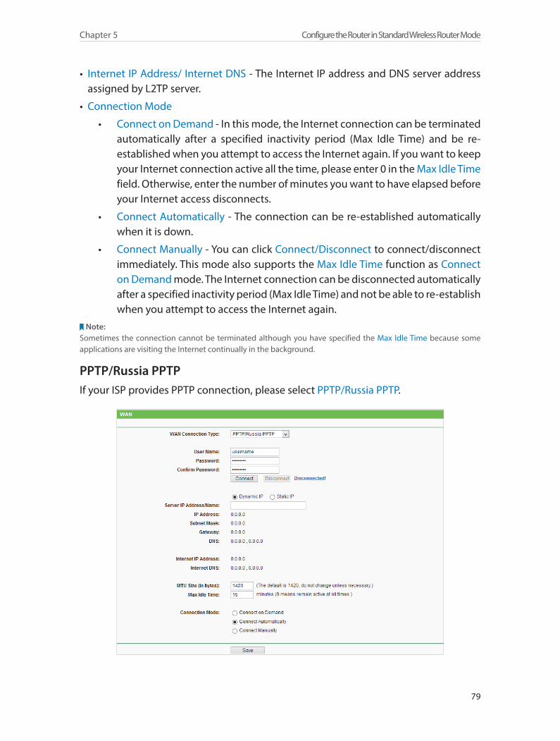
79
Chapter 5 Configure the Router in Standard Wireless Router Mode
• Internet IP Address/ Internet DNS - The Internet IP address and DNS server address assigned by L2TP server.
• Connection Mode
• Connect on Demand - In this mode, the Internet connection can be terminated automatically after a specified inactivity period (Max Idle Time) and be re-established when you attempt to access the Internet again. If you want to keep your Internet connection active all the time, please enter 0 in the Max Idle Time field. Otherwise, enter the number of minutes you want to have elapsed before your Internet access disconnects.
• Connect Automatically - The connection can be re-established automatically when it is down.
• Connect Manually - You can click Connect/Disconnect to connect/disconnect immediately. This mode also supports the Max Idle Time function as Connect on Demand mode. The Internet connection can be disconnected automatically after a specified inactivity period (Max Idle Time) and not be able to re-establish when you attempt to access the Internet again.
Note:Sometimes the connection cannot be terminated although you have specified the Max Idle Time because some applications are visiting the Internet continually in the background.
PPTP/Russia PPTPIf your ISP provides PPTP connection, please select PPTP/Russia PPTP.
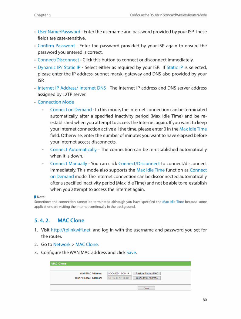
80
Chapter 5 Configure the Router in Standard Wireless Router Mode
• User Name/Password - Enter the username and password provided by your ISP. These fields are case-sensitive.
• Confirm Password - Enter the password provided by your ISP again to ensure the password you entered is correct.
• Connect/Disconnect - Click this button to connect or disconnect immediately.
• Dynamic IP/ Static IP - Select either as required by your ISP. If Static IP is selected, please enter the IP address, subnet marsk, gateway and DNS also provided by your ISP.
• Internet IP Address/ Internet DNS - The Internet IP address and DNS server address assigned by L2TP server.
• Connection Mode
• Connect on Demand - In this mode, the Internet connection can be terminated automatically after a specified inactivity period (Max Idle Time) and be re-established when you attempt to access the Internet again. If you want to keep your Internet connection active all the time, please enter 0 in the Max Idle Time field. Otherwise, enter the number of minutes you want to have elapsed before your Internet access disconnects.
• Connect Automatically - The connection can be re-established automatically when it is down.
• Connect Manually - You can click Connect/Disconnect to connect/disconnect immediately. This mode also supports the Max Idle Time function as Connect on Demand mode. The Internet connection can be disconnected automatically after a specified inactivity period (Max Idle Time) and not be able to re-establish when you attempt to access the Internet again.
Note:Sometimes the connection cannot be terminated although you have specified the Max Idle Time because some applications are visiting the Internet continually in the background.
5. 4. 2. MAC Clone
1. Visit http://tplinkwifi.net, and log in with the username and password you set for the router.
2. Go to Network > MAC Clone.
3. Configure the WAN MAC address and click Save.
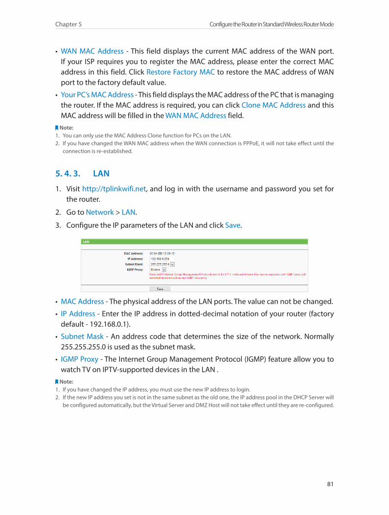
81
Chapter 5 Configure the Router in Standard Wireless Router Mode
• WAN MAC Address - This field displays the current MAC address of the WAN port. If your ISP requires you to register the MAC address, please enter the correct MAC address in this field. Click Restore Factory MAC to restore the MAC address of WAN port to the factory default value.
• Your PC’s MAC Address - This field displays the MAC address of the PC that is managing the router. If the MAC address is required, you can click Clone MAC Address and this MAC address will be filled in the WAN MAC Address field.
Note:1. You can only use the MAC Address Clone function for PCs on the LAN.2. If you have changed the WAN MAC address when the WAN connection is PPPoE, it will not take effect until the
connection is re-established.
5. 4. 3. LAN
1. Visit http://tplinkwifi.net, and log in with the username and password you set for the router.
2. Go to Network > LAN.
3. Configure the IP parameters of the LAN and click Save.
• MAC Address - The physical address of the LAN ports. The value can not be changed.
• IP Address - Enter the IP address in dotted-decimal notation of your router (factory default - 192.168.0.1).
• Subnet Mask - An address code that determines the size of the network. Normally 255.255.255.0 is used as the subnet mask.
• IGMP Proxy - The Internet Group Management Protocol (IGMP) feature allow you to watch TV on IPTV-supported devices in the LAN .
Note:1. If you have changed the IP address, you must use the new IP address to login.2. If the new IP address you set is not in the same subnet as the old one, the IP address pool in the DHCP Server will
be configured automatically, but the Virtual Server and DMZ Host will not take effect until they are re-configured.
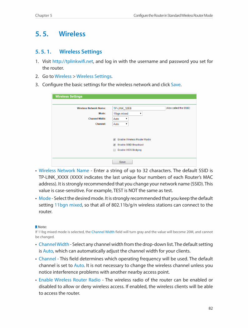
82
Chapter 5 Configure the Router in Standard Wireless Router Mode
5. 5. Wireless
5. 5. 1. Wireless Settings
1. Visit http://tplinkwifi.net, and log in with the username and password you set for the router.
2. Go to Wireless > Wireless Settings.
3. Configure the basic settings for the wireless network and click Save.
• Wireless Network Name - Enter a string of up to 32 characters. The default SSID is TP-LINK_XXXX (XXXX indicates the last unique four numbers of each Router’s MAC address). It is strongly recommended that you change your network name (SSID). This value is case-sensitive. For example, TEST is NOT the same as test.
• Mode - Select the desired mode. It is strongly recommended that you keep the default setting 11bgn mixed, so that all of 802.11b/g/n wireless stations can connect to the router.
Note:If 11bg mixed mode is selected, the Channel Width field will turn gray and the value will become 20M, and cannot be changed.
• Channel Width - Select any channel width from the drop-down list. The default setting is Auto, which can automatically adjust the channel width for your clients.
• Channel - This field determines which operating frequency will be used. The default channel is set to Auto. It is not necessary to change the wireless channel unless you notice interference problems with another nearby access point.
• Enable Wireless Router Radio - The wireless radio of the router can be enabled or disabled to allow or deny wireless access. If enabled, the wireless clients will be able to access the router.
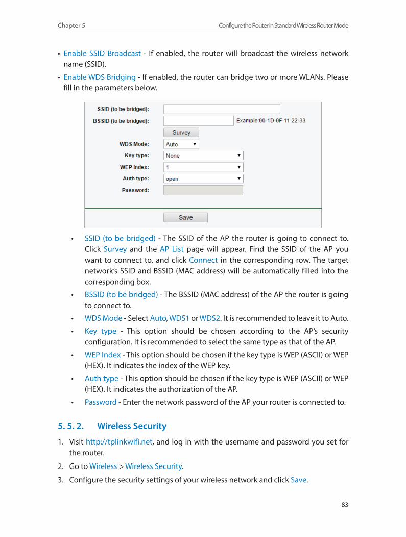
83
Chapter 5 Configure the Router in Standard Wireless Router Mode
• Enable SSID Broadcast - If enabled, the router will broadcast the wireless network name (SSID).
• Enable WDS Bridging - If enabled, the router can bridge two or more WLANs. Please fill in the parameters below.
• SSID (to be bridged) - The SSID of the AP the router is going to connect to. Click Survey and the AP List page will appear. Find the SSID of the AP you want to connect to, and click Connect in the corresponding row. The target network’s SSID and BSSID (MAC address) will be automatically filled into the corresponding box.
• BSSID (to be bridged) - The BSSID (MAC address) of the AP the router is going to connect to.
• WDS Mode - Select Auto, WDS1 or WDS2. It is recommended to leave it to Auto.
• Key type - This option should be chosen according to the AP’s security configuration. It is recommended to select the same type as that of the AP.
• WEP Index - This option should be chosen if the key type is WEP (ASCII) or WEP (HEX). It indicates the index of the WEP key.
• Auth type - This option should be chosen if the key type is WEP (ASCII) or WEP (HEX). It indicates the authorization of the AP.
• Password - Enter the network password of the AP your router is connected to.
5. 5. 2. Wireless Security
1. Visit http://tplinkwifi.net, and log in with the username and password you set for the router.
2. Go to Wireless > Wireless Security.
3. Configure the security settings of your wireless network and click Save.
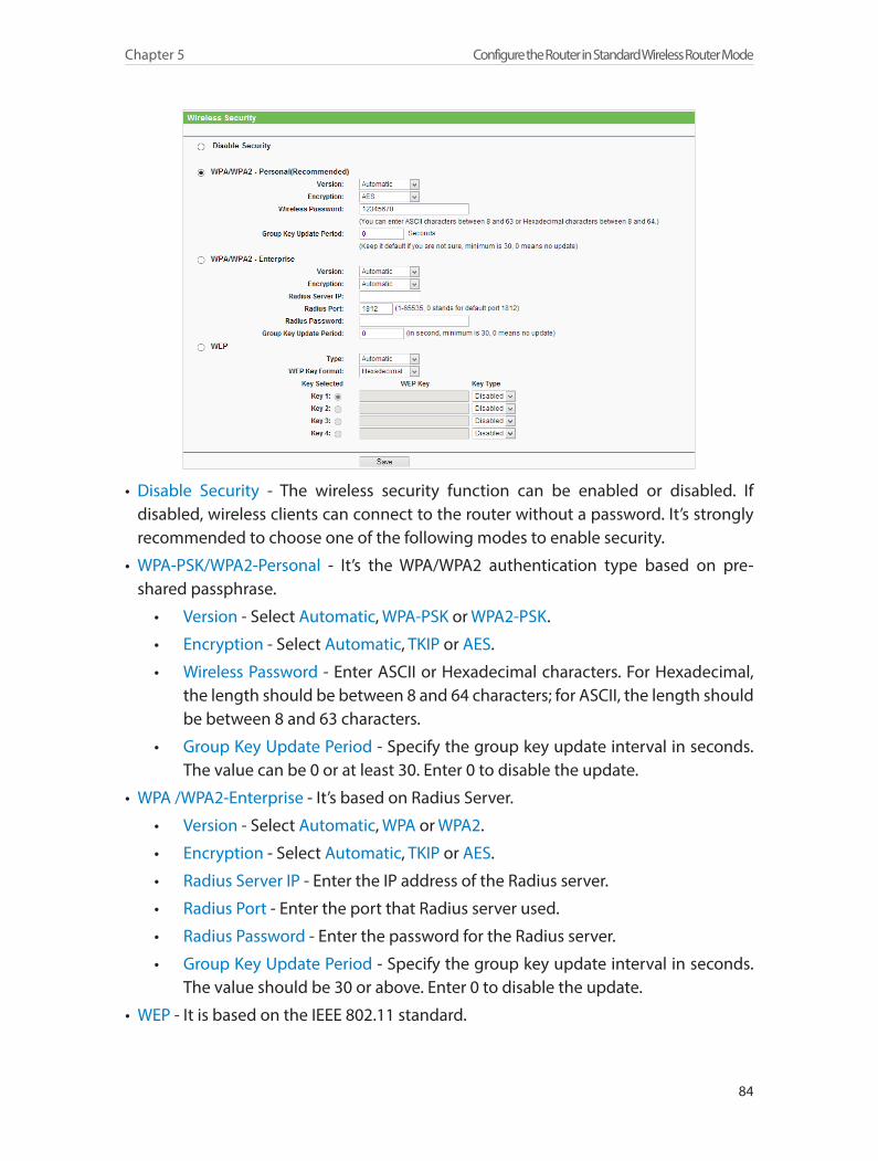
84
Chapter 5 Configure the Router in Standard Wireless Router Mode
• Disable Security - The wireless security function can be enabled or disabled. If disabled, wireless clients can connect to the router without a password. It’s strongly recommended to choose one of the following modes to enable security.
• WPA-PSK/WPA2-Personal - It’s the WPA/WPA2 authentication type based on pre-shared passphrase.
• Version - Select Automatic, WPA-PSK or WPA2-PSK.
• Encryption - Select Automatic, TKIP or AES.
• Wireless Password - Enter ASCII or Hexadecimal characters. For Hexadecimal, the length should be between 8 and 64 characters; for ASCII, the length should be between 8 and 63 characters.
• Group Key Update Period - Specify the group key update interval in seconds. The value can be 0 or at least 30. Enter 0 to disable the update.
• WPA /WPA2-Enterprise - It’s based on Radius Server.
• Version - Select Automatic, WPA or WPA2.
• Encryption - Select Automatic, TKIP or AES.
• Radius Server IP - Enter the IP address of the Radius server.
• Radius Port - Enter the port that Radius server used.
• Radius Password - Enter the password for the Radius server.
• Group Key Update Period - Specify the group key update interval in seconds. The value should be 30 or above. Enter 0 to disable the update.
• WEP - It is based on the IEEE 802.11 standard.
85
Chapter 5 Configure the Router in Standard Wireless Router Mode
• Type - The default setting is Automatic, which can select Shared Key or Open System authentication type automatically based on the wireless client’s capability and request.
• WEP Key Format - Hexadecimal and ASCII formats are provided here. Hexadecimal format stands for any combination of hexadecimal digits (0-9, a-f, A-F) in the specified length. ASCII format stands for any combination of keyboard characters in the specified length.
• WEP Key (Password) - Select which of the four keys will be used and enter the matching WEP key. Make sure these values are identical on all wireless clients in your network.
• Key Type - Select the WEP key length (64-bit, 128-bit or 152-bit) for encryption. Disabled means this WEP key entry is invalid.
• 64-bit - Enter 10 hexadecimal digits (any combination of 0-9, a-f and A-F. Null key is not permitted) or 5 ASCII characters.
• 128-bit - Enter 26 hexadecimal digits (any combination of 0-9, a-f and A-F. Null key is not permitted) or 13 ASCII characters.
• 152-bit - Enter 32 hexadecimal digits (any combination of 0-9, a-f and A-F. Null key is not permitted) or 16 ASCII characters.
5. 5. 3. Wireless MAC Filtering
Wireless MAC Filtering is used to deny or allow specific wireless client devices to access your network by their MAC addresses.
Deny or allow specific wireless client devices to access my network by their MAC addresses.
For example, you want the wireless client A with the MAC address 00-0A-EB-B0-00-0B and the wireless client B with the MAC address 00-0A-EB-00-07-5F to access the router, but other wireless clients cannot access the router
1. Visit http://tplinkwifi.net, and log in with the username and password you set for the router.
2. Go to Wireless > Wireless MAC Filtering.
3. Click Enable to enable the Wireless MAC Filtering function.
4. Select Allow the stations specified by any enabled entries in the list to access as the filtering rule.
5. Delete all or disable all entries if there are any entries already.
6. Click Add New and fill in the blank.
I want to:
How can I do that?

86
Chapter 5 Configure the Router in Standard Wireless Router Mode
1 ) Enter the MAC address 00-0A-EB-B0-00-0B/00-0A-EB-00-07-5F in the MAC Address field.
2 ) Enter wireless client A/B in the Description field.3 ) Leave the status as Enabled.4 ) Click Save and click Back.
7. The configured filtering rules should be listed as the picture shows below.
Now only client A and client B can access your network.
5. 5. 4. Wireless Advanced
1. Visit http://tplinkwifi.net, and log in with the username and password you set for the router.
2. Go to Wireless > Wireless Advanced.
3. Configure the advanced settings of your wireless network and click Save.Note:
If you are not familiar with the setting items on this page, it’s strongly recommended to keep the provided default values; otherwise it may result in lower wireless network performance.
• Transmit Power - Select High, Middle or Low which you would like to specify for the router. High is the default setting and recommended.
Done!

87
Chapter 5 Configure the Router in Standard Wireless Router Mode
• Beacon Interval - Enter a value between 40-1000 milliseconds for Beacon Interval here. Beacon Interval value determines the time interval of the beacons. The beacons are the packets sent by the Router to synchronize a wireless network. The default value is 100.
• RTS Threshold - Here you can specify the RTS (Request to Send) Threshold. If the packet is larger than the specified RTS Threshold size, the Router will send RTS frames to a particular receiving station and negotiate the sending of a data frame. The default value is 2346.
• Fragmentation Threshold - This value is the maximum size determining whether packets will be fragmented. Setting a low value for the Fragmentation Threshold may result in poor network performance because of excessive packets. 2346 is the default setting and is recommended.
• DTIM Interval - This value determines the interval of the Delivery Traffic Indication Message (DTIM). A DTIM field is a countdown field informing clients of the next window for listening to broadcast and multicast messages. When the Router has buffered broadcast or multicast messages for associated clients, it sends the next DTIM with a DTIM Interval value. You can specify the value between 1-255 Beacon Intervals. The default value is 1, which indicates the DTIM Interval is the same as Beacon Interval.
• Enable WMM - WMM function can guarantee the packets with high-priority messages being transmitted preferentially. It is strongly recommended to enable this function.
• Enable Short GI - It is recommended to enable this function, for it will increase the data capacity by reducing the guard interval time.
• Enable AP Isolation - This function isolates all connected wireless stations so that wireless stations cannot access each other through WLAN. This function will be disabled if WDS/Bridge is enabled.
5. 5. 5. Wireless Statistics
1. Visit http://tplinkwifi.net, and log in with the username and password you set for the router.
2. Go to Wireless > Wireless Statistics to check the data packets sent and received by each client device connected to the router.
88
Chapter 5 Configure the Router in Standard Wireless Router Mode
• MAC Address - The MAC address of the connected wireless client.
• Current Status - The running status of the connected wireless client.
• Received Packets - Packets received by the wireless client.
• Sent Packets - Packets sent by the wireless client.
• Configure - The button is used for loading the item to the Wireless MAC Filtering list.
• Allow - If the Wireless MAC Filtering function is enabled, click this button to allow the client to access your network.
• Deny - If the Wireless MAC Filtering function is enabled, click this button to deny the client to access your network.
5. 6. Guest NetworkThis function allows you to provide Wi-Fi access for guests without disclosing your host network. When you have guests in your house, apartment, or workplace, you can create a guest network for them. In addition, you can customize guest network settings to ensure network security and privacy.
1. Visit http://tplinkwifi.net, and log in with the username and password you set for the router.
2. Go to Guest Network > Wireless Settings.
3. Enable the Guest Network function.
4. Create a network name for your guest network.
5. Select the Wireless Security type and create the Password of the guest network.
6. Select Schedule from the Access Time drop-down list and customize it for the guest network.
7. Click Save.
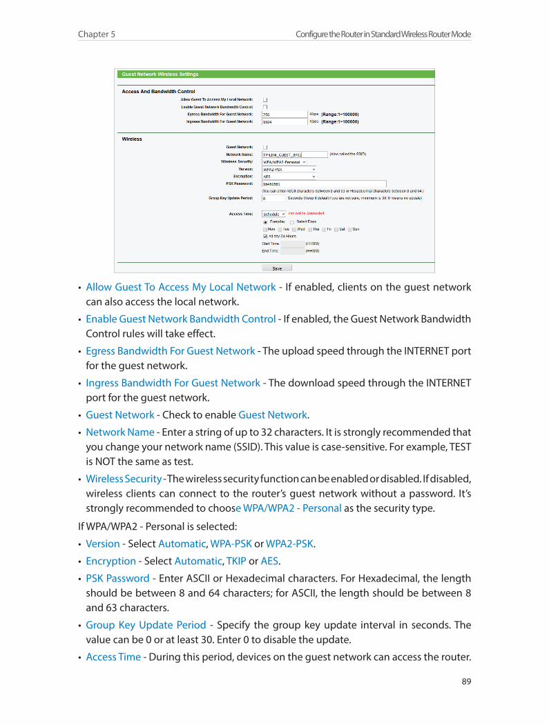
89
Chapter 5 Configure the Router in Standard Wireless Router Mode
• Allow Guest To Access My Local Network - If enabled, clients on the guest network can also access the local network.
• Enable Guest Network Bandwidth Control - If enabled, the Guest Network Bandwidth Control rules will take effect.
• Egress Bandwidth For Guest Network - The upload speed through the INTERNET port for the guest network.
• Ingress Bandwidth For Guest Network - The download speed through the INTERNET port for the guest network.
• Guest Network - Check to enable Guest Network.
• Network Name - Enter a string of up to 32 characters. It is strongly recommended that you change your network name (SSID). This value is case-sensitive. For example, TEST is NOT the same as test.
• Wireless Security - The wireless security function can be enabled or disabled. If disabled, wireless clients can connect to the router’s guest network without a password. It’s strongly recommended to choose WPA/WPA2 - Personal as the security type.
If WPA/WPA2 - Personal is selected:
• Version - Select Automatic, WPA-PSK or WPA2-PSK.
• Encryption - Select Automatic, TKIP or AES.
• PSK Password - Enter ASCII or Hexadecimal characters. For Hexadecimal, the length should be between 8 and 64 characters; for ASCII, the length should be between 8 and 63 characters.
• Group Key Update Period - Specify the group key update interval in seconds. The value can be 0 or at least 30. Enter 0 to disable the update.
• Access Time - During this period, devices on the guest network can access the router.
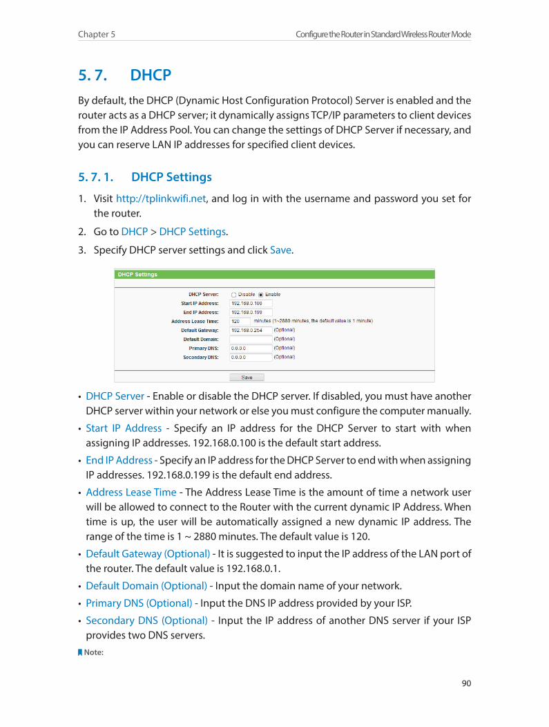
90
Chapter 5 Configure the Router in Standard Wireless Router Mode
5. 7. DHCPBy default, the DHCP (Dynamic Host Configuration Protocol) Server is enabled and the router acts as a DHCP server; it dynamically assigns TCP/IP parameters to client devices from the IP Address Pool. You can change the settings of DHCP Server if necessary, and you can reserve LAN IP addresses for specified client devices.
5. 7. 1. DHCP Settings
1. Visit http://tplinkwifi.net, and log in with the username and password you set for the router.
2. Go to DHCP > DHCP Settings.
3. Specify DHCP server settings and click Save.
• DHCP Server - Enable or disable the DHCP server. If disabled, you must have another DHCP server within your network or else you must configure the computer manually.
• Start IP Address - Specify an IP address for the DHCP Server to start with when assigning IP addresses. 192.168.0.100 is the default start address.
• End IP Address - Specify an IP address for the DHCP Server to end with when assigning IP addresses. 192.168.0.199 is the default end address.
• Address Lease Time - The Address Lease Time is the amount of time a network user will be allowed to connect to the Router with the current dynamic IP Address. When time is up, the user will be automatically assigned a new dynamic IP address. The range of the time is 1 ~ 2880 minutes. The default value is 120.
• Default Gateway (Optional) - It is suggested to input the IP address of the LAN port of the router. The default value is 192.168.0.1.
• Default Domain (Optional) - Input the domain name of your network.
• Primary DNS (Optional) - Input the DNS IP address provided by your ISP.
• Secondary DNS (Optional) - Input the IP address of another DNS server if your ISP provides two DNS servers.
Note:
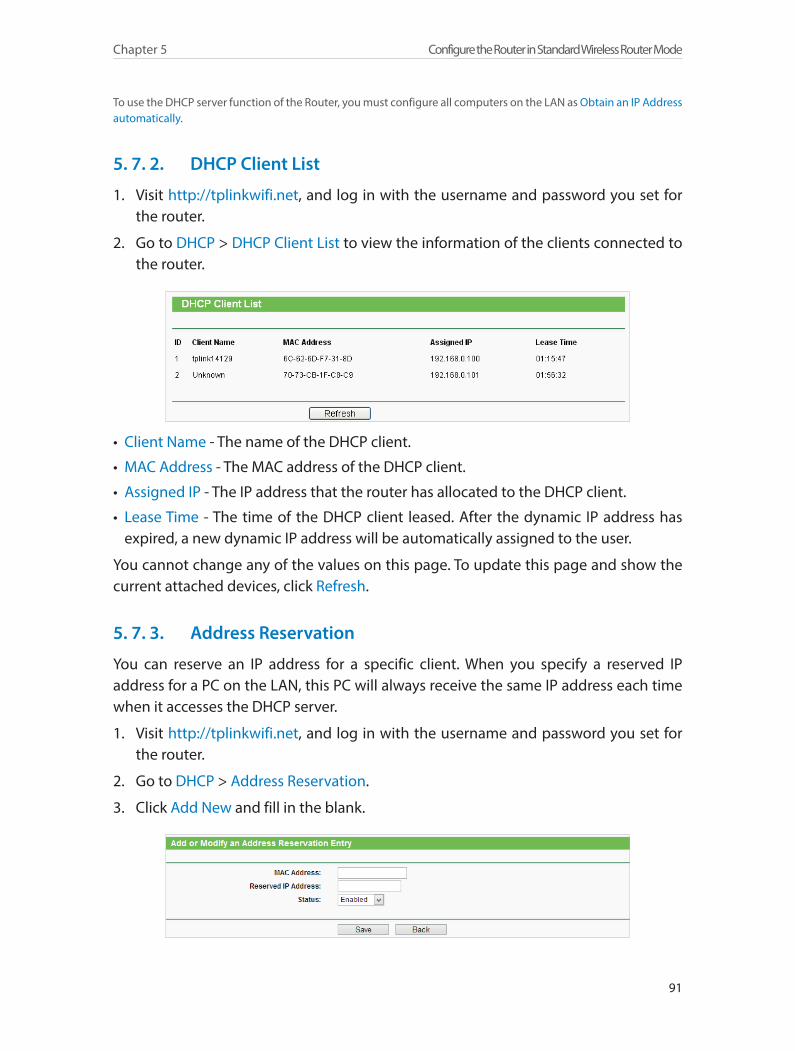
91
Chapter 5 Configure the Router in Standard Wireless Router Mode
To use the DHCP server function of the Router, you must configure all computers on the LAN as Obtain an IP Address automatically.
5. 7. 2. DHCP Client List
1. Visit http://tplinkwifi.net, and log in with the username and password you set for the router.
2. Go to DHCP > DHCP Client List to view the information of the clients connected to the router.
• Client Name - The name of the DHCP client.
• MAC Address - The MAC address of the DHCP client.
• Assigned IP - The IP address that the router has allocated to the DHCP client.
• Lease Time - The time of the DHCP client leased. After the dynamic IP address has expired, a new dynamic IP address will be automatically assigned to the user.
You cannot change any of the values on this page. To update this page and show the current attached devices, click Refresh.
5. 7. 3. Address Reservation
You can reserve an IP address for a specific client. When you specify a reserved IP address for a PC on the LAN, this PC will always receive the same IP address each time when it accesses the DHCP server.
1. Visit http://tplinkwifi.net, and log in with the username and password you set for the router.
2. Go to DHCP > Address Reservation.
3. Click Add New and fill in the blank.
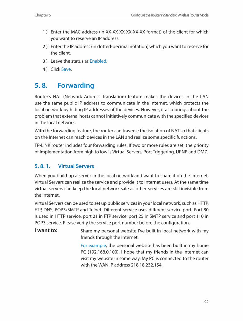
92
Chapter 5 Configure the Router in Standard Wireless Router Mode
1 ) Enter the MAC address (in XX-XX-XX-XX-XX-XX format) of the client for which you want to reserve an IP address.
2 ) Enter the IP address (in dotted-decimal notation) which you want to reserve for the client.
3 ) Leave the status as Enabled.
4 ) Click Save.
5. 8. ForwardingRouter’s NAT (Network Address Translation) feature makes the devices in the LAN use the same public IP address to communicate in the Internet, which protects the local network by hiding IP addresses of the devices. However, it also brings about the problem that external hosts cannot initiatively communicate with the specified devices in the local network.
With the forwarding feature, the router can traverse the isolation of NAT so that clients on the Internet can reach devices in the LAN and realize some specific functions.
TP-LINK router includes four forwarding rules. If two or more rules are set, the priority of implementation from high to low is Virtual Servers, Port Triggering, UPNP and DMZ.
5. 8. 1. Virtual Servers
When you build up a server in the local network and want to share it on the Internet, Virtual Servers can realize the service and provide it to Internet users. At the same time virtual servers can keep the local network safe as other services are still invisible from the Internet.
Virtual Servers can be used to set up public services in your local network, such as HTTP, FTP, DNS, POP3/SMTP and Telnet. Different service uses different service port. Port 80 is used in HTTP service, port 21 in FTP service, port 25 in SMTP service and port 110 in POP3 service. Please verify the service port number before the configuration.
Share my personal website I’ve built in local network with my friends through the Internet.
For example, the personal website has been built in my home PC (192.168.0.100). I hope that my friends in the Internet can visit my website in some way. My PC is connected to the router with the WAN IP address 218.18.232.154.
I want to:
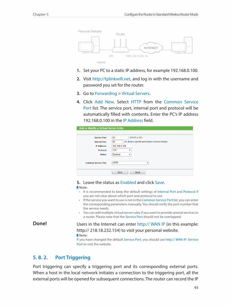
93
Chapter 5 Configure the Router in Standard Wireless Router Mode
Router
WAN: 218.18.232.154LAN
Home
Personal Website
1. Set your PC to a static IP address, for example 192.168.0.100.
2. Visit http://tplinkwifi.net, and log in with the username and password you set for the router.
3. Go to Forwarding > Virtual Servers.
4. Click Add New. Select HTTP from the Common Service Port list. The service port, internal port and protocol will be automatically filled with contents. Enter the PC’s IP address 192.168.0.100 in the IP Address field.
5. Leave the status as Enabled and click Save.Note:• It is recommended to keep the default settings of Internal Port and Protocol if
you are not clear about which port and protocol to use.• If the service you want to use is not in the Common Service Port list, you can enter
the corresponding parameters manually. You should verify the port number that the service needs.
• You can add multiple virtual server rules if you want to provide several services in a router. Please note that the Service Port should not be overlapped.
Users in the Internet can enter http:// WAN IP (in this example: http:// 218.18.232.154) to visit your personal website.
Note:If you have changed the default Service Port, you should use http:// WAN IP: Service Port to visit the website.
5. 8. 2. Port Triggering
Port triggering can specify a triggering port and its corresponding external ports. When a host in the local network initiates a connection to the triggering port, all the external ports will be opened for subsequent connections. The router can record the IP
Done!
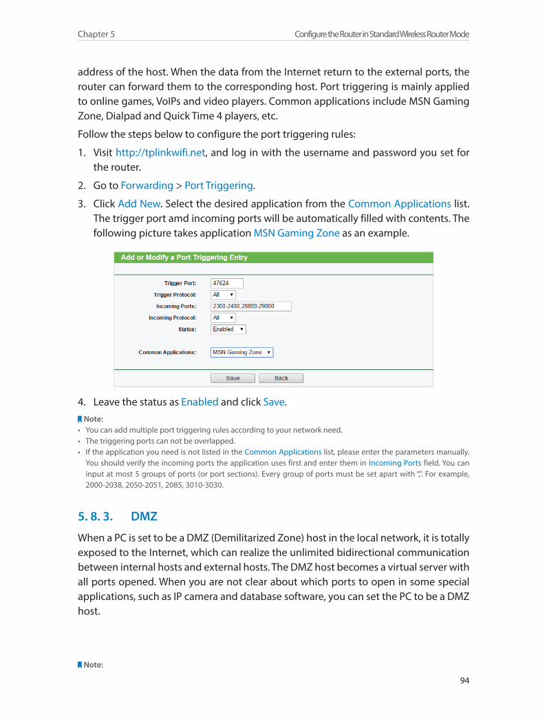
94
Chapter 5 Configure the Router in Standard Wireless Router Mode
address of the host. When the data from the Internet return to the external ports, the router can forward them to the corresponding host. Port triggering is mainly applied to online games, VoIPs and video players. Common applications include MSN Gaming Zone, Dialpad and Quick Time 4 players, etc.
Follow the steps below to configure the port triggering rules:
1. Visit http://tplinkwifi.net, and log in with the username and password you set for the router.
2. Go to Forwarding > Port Triggering.
3. Click Add New. Select the desired application from the Common Applications list. The trigger port amd incoming ports will be automatically filled with contents. The following picture takes application MSN Gaming Zone as an example.
4. Leave the status as Enabled and click Save.Note:
• You can add multiple port triggering rules according to your network need.• The triggering ports can not be overlapped.• If the application you need is not listed in the Common Applications list, please enter the parameters manually.
You should verify the incoming ports the application uses first and enter them in Incoming Ports field. You can input at most 5 groups of ports (or port sections). Every group of ports must be set apart with “,”. For example, 2000-2038, 2050-2051, 2085, 3010-3030.
5. 8. 3. DMZ
When a PC is set to be a DMZ (Demilitarized Zone) host in the local network, it is totally exposed to the Internet, which can realize the unlimited bidirectional communication between internal hosts and external hosts. The DMZ host becomes a virtual server with all ports opened. When you are not clear about which ports to open in some special applications, such as IP camera and database software, you can set the PC to be a DMZ host.
Note:

95
Chapter 5 Configure the Router in Standard Wireless Router Mode
DMZ is more applicable in the situation that users are not clear about which ports to open. When it is enabled, the DMZ host is totally exposed to the Internet, which may bring some potential safety hazard. If DMZ is not in use, please disable it in time.
Make the home PC join the Internet online game without port restriction.
For example, due to some port restriction, when playing the online games, you can login normally but cannot join a team with other players. To solve this problem, set your PC as a DMZ with all ports opened.
1. Assign a static IP address to your PC, for example 192.168.0.100.
2. Visit http://tplinkwifi.net, and log in with the username and password you set for the router.
3. Go to Forwarding > DMZ.
4. Select Enable and enter the IP address 192.168.0.100 in the DMZ Host IP Address filed.
5. Click Save.
You’ve set your PC to a DMZ host and now you can make a team to game with other players.
5. 8. 4. UPnP
UPnP (Universal Plug and Play) protocol allows the applications or host devices to automatically find the front-end NAT device and send request to it to open the corresponding ports. With UPnP enabled, the applications or host devices in the both sides of the NAT device can freely communicate with each other realizing the seamless connection of the network. You may need to enable the UPnP if you want to use applications for multiplayer gaming, peer-to-peer connections, real-time communication (such as VoIP or telephone conference) or remote assistance, etc.
Tips:• UPnP is enabled by default in this router.• Only the application supporting UPnP protocol can use this feature.• UPnP feature needs the support of operating system (e.g. Windows Vista/ Windows 7/ Windows 8, etc. Some of
operating system need to install the UPnP components).
I want to:
How can I do that?
Done!

96
Chapter 5 Configure the Router in Standard Wireless Router Mode
For example, when you connect your Xbox to the router which is connected to the Internet to play online games, UPnP will send request to the router to open the corresponding ports allowing the following data penetrating the NAT to transmit. Therefore, you can play Xbox online games without a hitch.
RouterXbox
LAN WAN
If necessary, you can follow the steps to change the status of UPnP.
1. Visit http://tplinkwifi.net, and log in with the username and password you set for the router.
2. Go to Forwarding > UPnP.
3. Click Disable or Enable according to your needs.
5. 9. SecurityThis function allows you to protect your home network from cyber attacks and unauthorized users by implementing these network security functions.
5. 9. 1. Basic Security
1. Visit http://tplinkwifi.net, and log in with the username and password you set for the router.
2. Go to Security > Basic Security, and you can enable or disable the security functions.

97
Chapter 5 Configure the Router in Standard Wireless Router Mode
• Firewall - A firewall protects your network from Internet attacks.
• SPI Firewall - SPI (Stateful Packet Inspection, also known as dynamic packet filtering) helps to prevent cyber attacks by tracking more state per session. It validates that the traffic passing through the session conforms to the protocol. SPI Firewall is enabled by default.
• VPN - VPN Passthrough must be enabled if you want to allow VPN tunnels using IPSec, PPTP or L2TP protocols to pass through the router’s firewall.
• PPTP Passthrough - Point-to-Point Tunneling Protocol (PPTP) allows the Point-to-Point Protocol (PPP) to be tunneled through an IP network. If you want to allow PPTP tunnels to pass through the router, you can keep the default (Enabled).
• L2TP Passthrough - Layer 2 Tunneling Protocol (L2TP) is the method used to enable Point-to-Point sessions via the Internet on the Layer 2 level. If you want to allow L2TP tunnels to pass through the router, you can keep the default (Enabled).
• IPSec Passthrough - Internet Protocol Security (IPSec) is a suite of protocols for ensuring private, secure communications over Internet Protocol (IP) networks, through the use of cryptographic security services. If you want to allow IPSec tunnels to pass through the router, you can keep the default (Enabled).
• ALG - It is recommended to enable Application Layer Gateway (ALG) because ALG allows customized Network Address Translation (NAT) traversal filters to be plugged
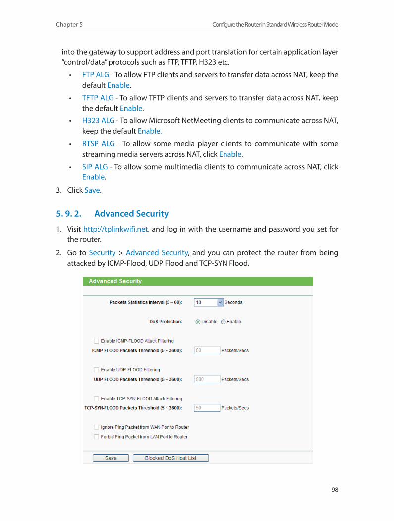
98
Chapter 5 Configure the Router in Standard Wireless Router Mode
into the gateway to support address and port translation for certain application layer “control/data” protocols such as FTP, TFTP, H323 etc.
• FTP ALG - To allow FTP clients and servers to transfer data across NAT, keep the default Enable.
• TFTP ALG - To allow TFTP clients and servers to transfer data across NAT, keep the default Enable.
• H323 ALG - To allow Microsoft NetMeeting clients to communicate across NAT, keep the default Enable.
• RTSP ALG - To allow some media player clients to communicate with some streaming media servers across NAT, click Enable.
• SIP ALG - To allow some multimedia clients to communicate across NAT, click Enable.
3. Click Save.
5. 9. 2. Advanced Security
1. Visit http://tplinkwifi.net, and log in with the username and password you set for the router.
2. Go to Security > Advanced Security, and you can protect the router from being attacked by ICMP-Flood, UDP Flood and TCP-SYN Flood.
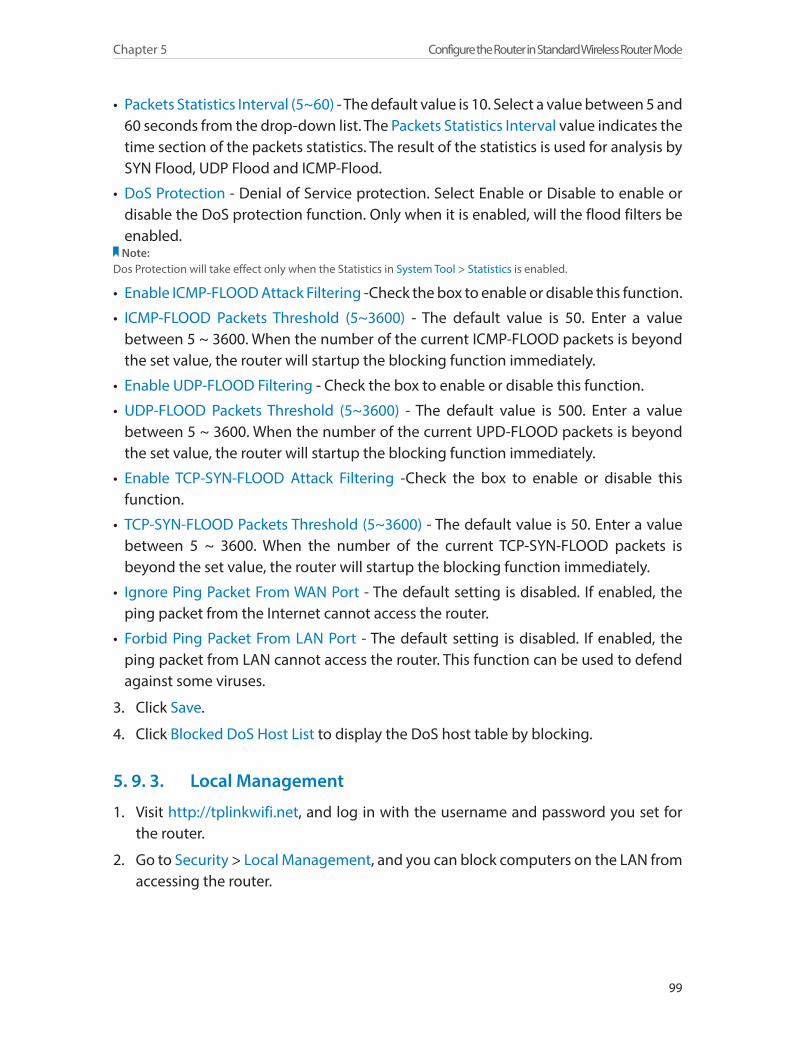
99
Chapter 5 Configure the Router in Standard Wireless Router Mode
• Packets Statistics Interval (5~60) - The default value is 10. Select a value between 5 and 60 seconds from the drop-down list. The Packets Statistics Interval value indicates the time section of the packets statistics. The result of the statistics is used for analysis by SYN Flood, UDP Flood and ICMP-Flood.
• DoS Protection - Denial of Service protection. Select Enable or Disable to enable or disable the DoS protection function. Only when it is enabled, will the flood filters be enabled.
Note:Dos Protection will take effect only when the Statistics in System Tool > Statistics is enabled.
• Enable ICMP-FLOOD Attack Filtering -Check the box to enable or disable this function.
• ICMP-FLOOD Packets Threshold (5~3600) - The default value is 50. Enter a value between 5 ~ 3600. When the number of the current ICMP-FLOOD packets is beyond the set value, the router will startup the blocking function immediately.
• Enable UDP-FLOOD Filtering - Check the box to enable or disable this function.
• UDP-FLOOD Packets Threshold (5~3600) - The default value is 500. Enter a value between 5 ~ 3600. When the number of the current UPD-FLOOD packets is beyond the set value, the router will startup the blocking function immediately.
• Enable TCP-SYN-FLOOD Attack Filtering -Check the box to enable or disable this function.
• TCP-SYN-FLOOD Packets Threshold (5~3600) - The default value is 50. Enter a value between 5 ~ 3600. When the number of the current TCP-SYN-FLOOD packets is beyond the set value, the router will startup the blocking function immediately.
• Ignore Ping Packet From WAN Port - The default setting is disabled. If enabled, the ping packet from the Internet cannot access the router.
• Forbid Ping Packet From LAN Port - The default setting is disabled. If enabled, the ping packet from LAN cannot access the router. This function can be used to defend against some viruses.
3. Click Save.
4. Click Blocked DoS Host List to display the DoS host table by blocking.
5. 9. 3. Local Management
1. Visit http://tplinkwifi.net, and log in with the username and password you set for the router.
2. Go to Security > Local Management, and you can block computers on the LAN from accessing the router.
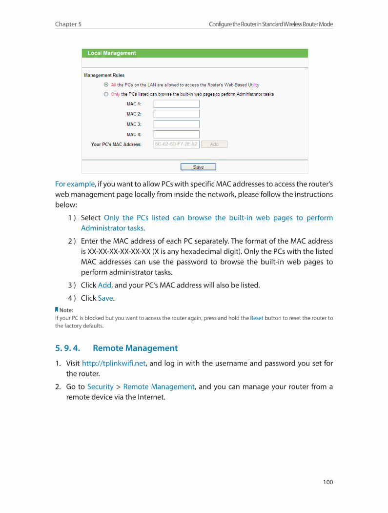
100
Chapter 5 Configure the Router in Standard Wireless Router Mode
For example, if you want to allow PCs with specific MAC addresses to access the router’s web management page locally from inside the network, please follow the instructions below:
1 ) Select Only the PCs listed can browse the built-in web pages to perform Administrator tasks.
2 ) Enter the MAC address of each PC separately. The format of the MAC address is XX-XX-XX-XX-XX-XX (X is any hexadecimal digit). Only the PCs with the listed MAC addresses can use the password to browse the built-in web pages to perform administrator tasks.
3 ) Click Add, and your PC’s MAC address will also be listed.
4 ) Click Save. Note:
If your PC is blocked but you want to access the router again, press and hold the Reset button to reset the router to the factory defaults.
5. 9. 4. Remote Management
1. Visit http://tplinkwifi.net, and log in with the username and password you set for the router.
2. Go to Security > Remote Management, and you can manage your router from a remote device via the Internet.

101
Chapter 5 Configure the Router in Standard Wireless Router Mode
• Web Management Port - Web browser access normally uses the standard HTTP service port 80. This router’s default remote management web port number is 80. For higher security, you can change the remote management web port to a custom port by entering a number between 1 and 65534 but do not use the number of any common service port.
• Remote Management IP Address - This is the address you will use when accessing your router via a remote device. This function is disabled when the IP address is set to the default value of 0.0.0.0. To enable this function, change 0.0.0.0 to a valid IP address. If it is set to 255.255.255.255, then all the remote devices can access the router from the Internet.
Note:1. To access the router, enter your router’s WAN IP address in your browser’s address bar, followed by a colon and the
custom port number. For example, if your router’s WAN address is 202.96.12.8, and the port number used is 8080, please enter http://202.96.12.8:8080 in your browser. Later, you may be asked for the router’s password. After successfully entering the username and password, you will be able to access the router’s web management page.
2. Be sure to change the router’s default password for security purposes.
5. 10. Parental ControlsParental Controls allows you to block inappropriate and malicious websites, and control access to specific websites at specific time for your children’s devices.
For example, you want the children’s PC with the MAC address 00-11-22-33-44-AA can access www.tp-link.com on Saturday only while the parent PC with the MAC address 00-11-22-33-44-BB is without any restriction.
1. Visit http://tplinkwifi.net, and log in with the username and password you set for the router.
2. Go to Access Control > Schedule.
3. Click Add New to create a new schedule entry with Schedule Description as Schedule_1, Day as Sat and Time as all day-24 hours. And click Save.
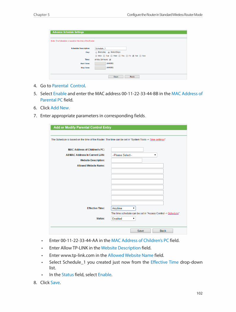
102
Chapter 5 Configure the Router in Standard Wireless Router Mode
4. Go to Parental Control.
5. Select Enable and enter the MAC address 00-11-22-33-44-BB in the MAC Address of Parental PC field.
6. Click Add New.
7. Enter appropriate parameters in corresponding fields.
• Enter 00-11-22-33-44-AA in the MAC Address of Children’s PC field.
• Enter Allow TP-LINK in the Website Description field.
• Enter www.tp-link.com in the Allowed Website Name field. • Select Schedule_1 you created just now from the Effective Time drop-down
list. • In the Status field, select Enable.
8. Click Save.
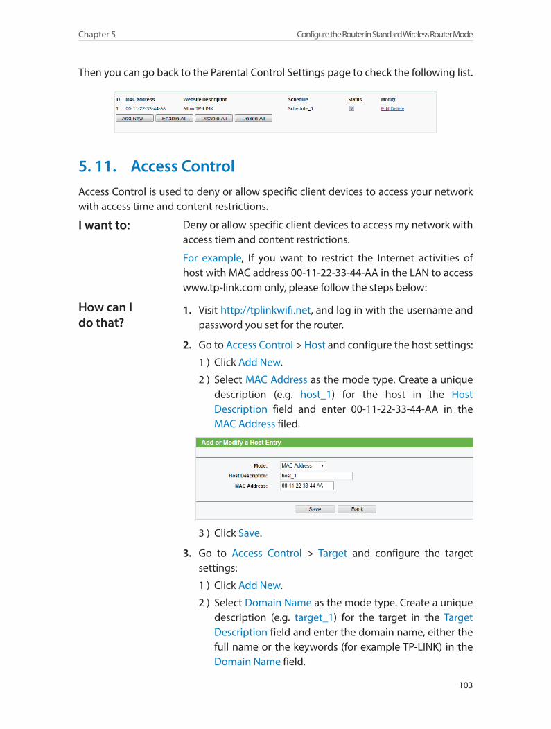
103
Chapter 5 Configure the Router in Standard Wireless Router Mode
Then you can go back to the Parental Control Settings page to check the following list.
5. 11. Access ControlAccess Control is used to deny or allow specific client devices to access your network with access time and content restrictions.
Deny or allow specific client devices to access my network with access tiem and content restrictions.
For example, If you want to restrict the Internet activities of host with MAC address 00-11-22-33-44-AA in the LAN to access www.tp-link.com only, please follow the steps below:
1. Visit http://tplinkwifi.net, and log in with the username and password you set for the router.
2. Go to Access Control > Host and configure the host settings:
1 ) Click Add New.
2 ) Select MAC Address as the mode type. Create a unique description (e.g. host_1) for the host in the Host Description field and enter 00-11-22-33-44-AA in the MAC Address filed.
3 ) Click Save.
3. Go to Access Control > Target and configure the target settings:
1 ) Click Add New.
2 ) Select Domain Name as the mode type. Create a unique description (e.g. target_1) for the target in the Target Description field and enter the domain name, either the full name or the keywords (for example TP-LINK) in the Domain Name field.
I want to:
How can I do that?
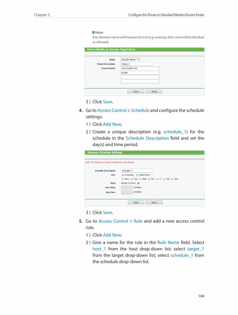
104
Chapter 5 Configure the Router in Standard Wireless Router Mode
Note:Any domain name with keywords in it (e.g. www.tp-link.com) will be blocked or allowed.
3 ) Click Save.
4. Go to Access Control > Schedule and configure the schedule settings:
1 ) Click Add New.
2 ) Create a unique description (e.g. schedule_1) for the schedule in the Schedule Description field and set the day(s) and time period.
3 ) Click Save.
5. Go to Access Control > Rule and add a new access control rule.
1 ) Click Add New.
2 ) Give a name for the rule in the Rule Name field. Select host_1 from the host drop-down list; select target_1 from the target drop-down list; select schedule_1 from the schedule drop-down list.
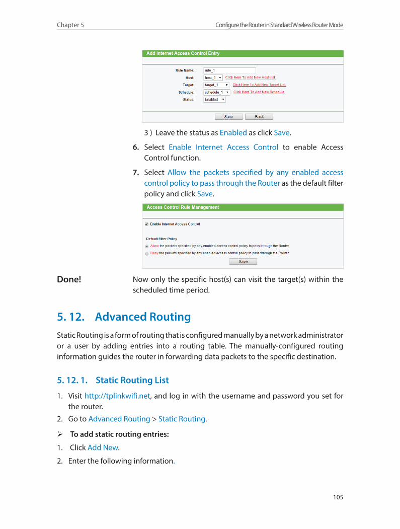
105
Chapter 5 Configure the Router in Standard Wireless Router Mode
3 ) Leave the status as Enabled as click Save.
6. Select Enable Internet Access Control to enable Access Control function.
7. Select Allow the packets specified by any enabled access control policy to pass through the Router as the default filter policy and click Save.
Now only the specific host(s) can visit the target(s) within the scheduled time period.
5. 12. Advanced RoutingStatic Routing is a form of routing that is configured manually by a network administrator or a user by adding entries into a routing table. The manually-configured routing information guides the router in forwarding data packets to the specific destination.
5. 12. 1. Static Routing List
1. Visit http://tplinkwifi.net, and log in with the username and password you set for the router.
2. Go to Advanced Routing > Static Routing.
¾ To add static routing entries:
1. Click Add New.
2. Enter the following information.
Done!
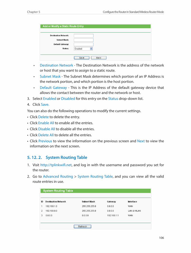
106
Chapter 5 Configure the Router in Standard Wireless Router Mode
• Destination Network - The Destination Network is the address of the network or host that you want to assign to a static route.
• Subnet Mask - The Subnet Mask determines which portion of an IP Address is the network portion, and which portion is the host portion.
• Default Gateway - This is the IP Address of the default gateway device that allows the contact between the router and the network or host.
3. Select Enabled or Disabled for this entry on the Status drop-down list.
4. Click Save.
You can also do the following operations to modify the current settings.
• Click Delete to delete the entry.
• Click Enable All to enable all the entries.
• Click Disable All to disable all the entries.
• Click Delete All to delete all the entries.
• Click Previous to view the information on the previous screen and Next to view the information on the next screen.
5. 12. 2. System Routing Table
1. Visit http://tplinkwifi.net, and log in with the username and password you set for the router.
2. Go to Advanced Routing > System Routing Table, and you can view all the valid route entries in use.
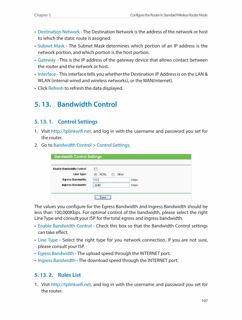
107
Chapter 5 Configure the Router in Standard Wireless Router Mode
• Destination Network - The Destination Network is the address of the network or host to which the static route is assigned.
• Subnet Mask - The Subnet Mask determines which portion of an IP address is the network portion, and which portion is the host portion.
• Gateway - This is the IP address of the gateway device that allows contact between the router and the network or host.
• Interface - This interface tells you whether the Destination IP Address is on the LAN & WLAN (internal wired and wireless networks), or the WAN(Internet).
• Click Refresh to refresh the data displayed.
5. 13. Bandwidth Control
5. 13. 1. Control Settings
1. Visit http://tplinkwifi.net, and log in with the username and password you set for the router.
2. Go to Bandwidth Control > Control Settings.
The values you configure for the Egress Bandwidth and Ingress Bandwidth should be less than 100,000Kbps. For optimal control of the bandwidth, please select the right Line Type and consult your ISP for the total egress and ingress bandwidth.
• Enable Bandwidth Control - Check this box so that the Bandwidth Control settings can take effect.
• Line Type - Select the right type for you network connection. If you are not sure, please consult your ISP.
• Egress Bandwidth - The upload speed through the INTERNET port.• Ingress Bandwidth - The download speed through the INTERNET port.
5. 13. 2. Rules List
1. Visit http://tplinkwifi.net, and log in with the username and password you set for the router.
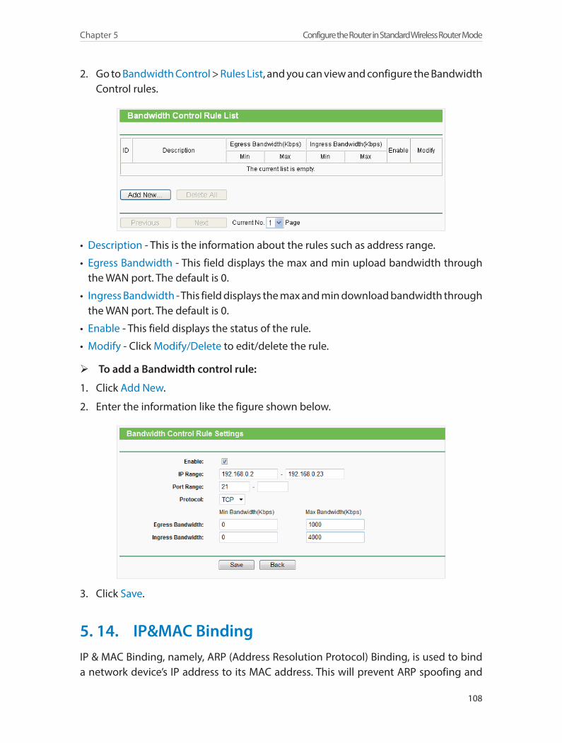
108
Chapter 5 Configure the Router in Standard Wireless Router Mode
2. Go to Bandwidth Control > Rules List, and you can view and configure the Bandwidth Control rules.
• Description - This is the information about the rules such as address range.
• Egress Bandwidth - This field displays the max and min upload bandwidth through the WAN port. The default is 0.
• Ingress Bandwidth - This field displays the max and min download bandwidth through the WAN port. The default is 0.
• Enable - This field displays the status of the rule.
• Modify - Click Modify/Delete to edit/delete the rule.
¾ To add a Bandwidth control rule:
1. Click Add New.
2. Enter the information like the figure shown below.
3. Click Save.
5. 14. IP&MAC BindingIP & MAC Binding, namely, ARP (Address Resolution Protocol) Binding, is used to bind a network device’s IP address to its MAC address. This will prevent ARP spoofing and

109
Chapter 5 Configure the Router in Standard Wireless Router Mode
other ARP attacks by denying network access to a device with a matching IP address in the ARP list, but with an unrecognized MAC address.
5. 14. 1. Binding Settings
1. Visit http://tplinkwifi.net, and log in with the username and password you set for the router.
2. Go to IP & MAC Binding > Binding Settings.
3. Select Enable for ARP Binding.
4. Click Save.
¾ To add IP & MAC Binding entries:
1. Click Add New.
2. Select the Bind checkbox.
3. Enter the MAC address and IP address.
4. Click Save.
¾ To modify or delete an existing entry:
1. Find the desired entry in the table.
2. Click Modify or Delete in the Modify column.
¾ To find an existing entry:
1. Click Find.
2. Enter the MAC address or IP address in the corresponding field.
3. Click Find on this page as shown below.
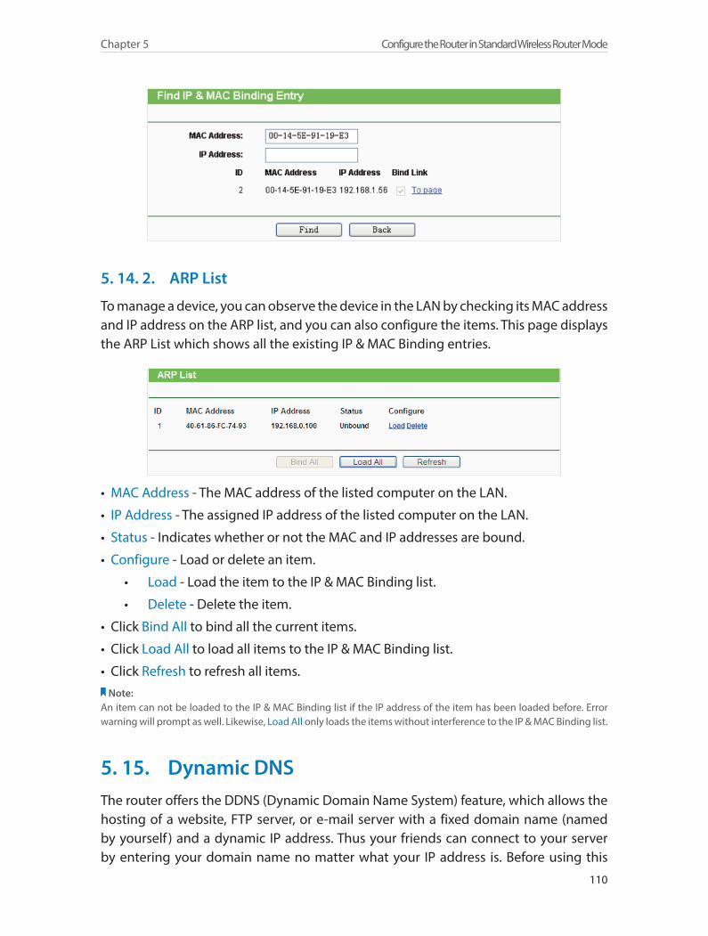
110
Chapter 5 Configure the Router in Standard Wireless Router Mode
5. 14. 2. ARP List
To manage a device, you can observe the device in the LAN by checking its MAC address and IP address on the ARP list, and you can also configure the items. This page displays the ARP List which shows all the existing IP & MAC Binding entries.
• MAC Address - The MAC address of the listed computer on the LAN.
• IP Address - The assigned IP address of the listed computer on the LAN.
• Status - Indicates whether or not the MAC and IP addresses are bound.
• Configure - Load or delete an item.
• Load - Load the item to the IP & MAC Binding list.
• Delete - Delete the item.
• Click Bind All to bind all the current items.
• Click Load All to load all items to the IP & MAC Binding list.
• Click Refresh to refresh all items.Note:
An item can not be loaded to the IP & MAC Binding list if the IP address of the item has been loaded before. Error warning will prompt as well. Likewise, Load All only loads the items without interference to the IP & MAC Binding list.
5. 15. Dynamic DNSThe router offers the DDNS (Dynamic Domain Name System) feature, which allows the hosting of a website, FTP server, or e-mail server with a fixed domain name (named by yourself ) and a dynamic IP address. Thus your friends can connect to your server by entering your domain name no matter what your IP address is. Before using this

111
Chapter 5 Configure the Router in Standard Wireless Router Mode
feature, you need to sign up for DDNS service providers such as www.comexe.cn, www.dyndns.org, or www.no-ip.com. The Dynamic DNS client service provider will give you a password or key.
1. Visit http://tplinkwifi.net, and log in with the username and password you set for the router.
2. Go to Dynamic DNS.
Comexe DDNSIf the dynamic DNS Service Provider you select is www.comexe.cn, the following page will appear.
To set up for DDNS, follow these instructions:
1. Enter the Domain Name received from your dynamic DNS service provider.
2. Enter the User Name for your DDNS account.
3. Enter the Password for your DDNS account.
4. Click Login.
5. Click Save.
• Connection Status - The status of the DDNS service connection is displayed here.
• Logout - Click Logout to log out of the DDNS service.
Dyndns DDNSIf the dynamic DNS Service Provider you select is www.dyn.com, the following page will appear.

112
Chapter 5 Configure the Router in Standard Wireless Router Mode
To set up for DDNS, follow these instructions:
1. Enter the User Name for your DDNS account.
2. Enter the Password for your DDNS account.
3. Enter the Domain Name you received from dynamic DNS service provider here.
4. Click Login.
5. Click Save.
• Connection Status - The status of the DDNS service connection is displayed here.
• Logout - Click Logout to log out of the DDNS service.
No-ip DDNSIf the dynamic DNS Service Provider you select is www.noip.com, the following page will appear.
To set up for DDNS, follow these instructions:
1. Enter the User Name for your DDNS account.
2. Enter the Password for your DDNS account.
3. Enter the Domain Name you received from dynamic DNS service provider.
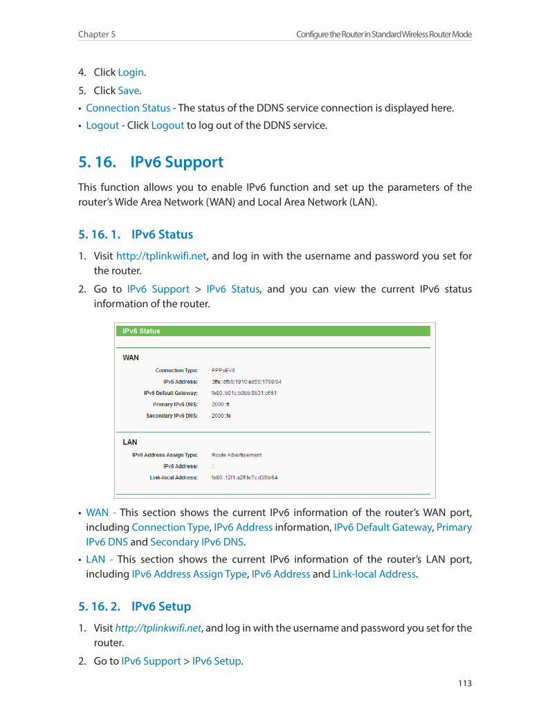
113
Chapter 5 Configure the Router in Standard Wireless Router Mode
4. Click Login.
5. Click Save.
• Connection Status - The status of the DDNS service connection is displayed here.
• Logout - Click Logout to log out of the DDNS service.
5. 16. IPv6 SupportThis function allows you to enable IPv6 function and set up the parameters of the router’s Wide Area Network (WAN) and Local Area Network (LAN).
5. 16. 1. IPv6 Status
1. Visit http://tplinkwifi.net, and log in with the username and password you set for the router.
2. Go to IPv6 Support > IPv6 Status, and you can view the current IPv6 status information of the router.
• WAN - This section shows the current IPv6 information of the router’s WAN port, including Connection Type, IPv6 Address information, IPv6 Default Gateway, Primary IPv6 DNS and Secondary IPv6 DNS.
• LAN - This section shows the current IPv6 information of the router’s LAN port, including IPv6 Address Assign Type, IPv6 Address and Link-local Address.
5. 16. 2. IPv6 Setup
1. Visit http://tplinkwifi.net, and log in with the username and password you set for the router.
2. Go to IPv6 Support > IPv6 Setup.
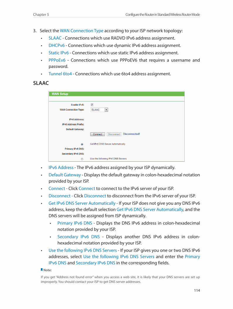
114
Chapter 5 Configure the Router in Standard Wireless Router Mode
3. Select the WAN Connection Type according to your ISP network topology:
• SLAAC - Connections which use RADVD IPv6 address assignment.
• DHCPv6 - Connections which use dynamic IPv6 address assignment.
• Static IPv6 - Connections which use static IPv6 address assignment.
• PPPoEv6 - Connections which use PPPoEV6 that requires a username and password.
• Tunnel 6to4 - Connections which use 6to4 address assignment.
SLAAC
• IPv6 Address - The IPv6 address assigned by your ISP dynamically.
• Default Gateway - Displays the default gateway in colon-hexadecimal notation provided by your ISP.
• Connect - Click Connect to connect to the IPv6 server of your ISP.
• Disconnect - Click Disconnect to disconnect from the IPv6 server of your ISP.
• Get IPv6 DNS Server Automatically - If your ISP does not give you any DNS IPv6 address, keep the default selection Get IPv6 DNS Server Automatically, and the DNS servers will be assigned from ISP dynamically.
• Primary IPv6 DNS - Displays the DNS IPv6 address in colon-hexadecimal notation provided by your ISP.
• Secondary IPv6 DNS - Displays another DNS IPv6 address in colon-hexadecimal notation provided by your ISP.
• Use the following IPv6 DNS Servers - If your ISP gives you one or two DNS IPv6 addresses, select Use the following IPv6 DNS Servers and enter the Primary IPv6 DNS and Secondary IPv6 DNS in the corresponding fields.
Note:
If you get “Address not found error” when you access a web site, it is likely that your DNS servers are set up improperly. You should contact your ISP to get DNS server addresses.

115
Chapter 5 Configure the Router in Standard Wireless Router Mode
DHCPv6
• IPv6 Address - The IPv6 address assigned by your ISP dynamically.
• Default Gateway - Displays the default gateway in colon-hexadecimal notation provided by your ISP.
• Renew - Click Renew to renew the IPv6 parameters from your ISP.
• Release - Click Release to release the IPv6 parameters from your ISP.
• Get IPv6 DNS Server Automatically - If your ISP does not give you any DNS IPv6 address, keep the default selection Get IPv6 DNS Server Automatically, and the DNS servers will be assigned from ISP dynamically.
• Primary IPv6 DNS - Displays the DNS IPv6 address in colon-hexadecimal notation provided by your ISP.
• Secondary IPv6 DNS - Displays another DNS IPv6 address in colon-hexadecimal notation provided by your ISP.
• Use the following IPv6 DNS Servers - If your ISP gives you one or two DNS IPv6 addresses, select Use the following IPv6 DNS Servers and enter the Primary IPv6 DNS and Secondary IPv6 DNS in the corresponding fields.
Note:
If you get “Address not found error” when you access a web site, it is likely that your DNS servers are set up improperly. You should contact your ISP to get DNS server addresses.
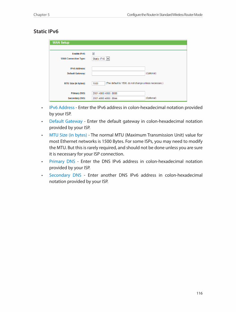
116
Chapter 5 Configure the Router in Standard Wireless Router Mode
Static IPv6
• IPv6 Address - Enter the IPv6 address in colon-hexadecimal notation provided by your ISP.
• Default Gateway - Enter the default gateway in colon-hexadecimal notation provided by your ISP.
• MTU Size (in bytes) - The normal MTU (Maximum Transmission Unit) value for most Ethernet networks is 1500 Bytes. For some ISPs, you may need to modify the MTU. But this is rarely required, and should not be done unless you are sure it is necessary for your ISP connection.
• Primary DNS - Enter the DNS IPv6 address in colon-hexadecimal notation provided by your ISP.
• Secondary DNS - Enter another DNS IPv6 address in colon-hexadecimal notation provided by your ISP.
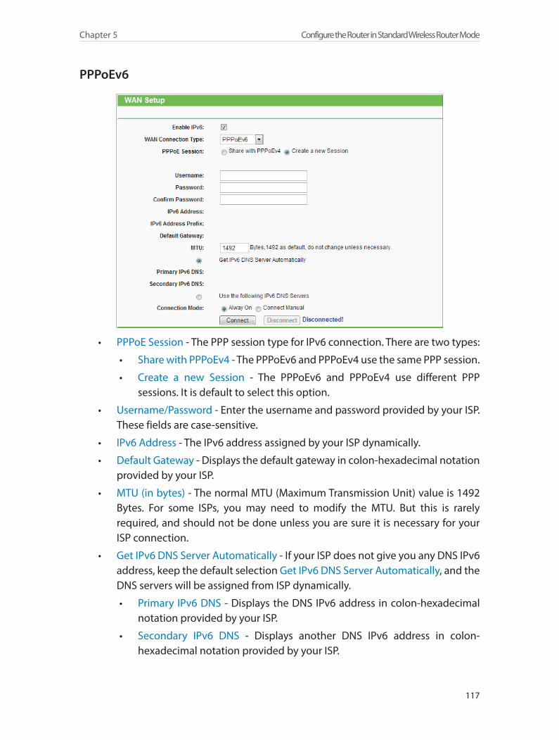
117
Chapter 5 Configure the Router in Standard Wireless Router Mode
PPPoEv6
• PPPoE Session - The PPP session type for IPv6 connection. There are two types:
• Share with PPPoEv4 - The PPPoEv6 and PPPoEv4 use the same PPP session.
• Create a new Session - The PPPoEv6 and PPPoEv4 use different PPP sessions. It is default to select this option.
• Username/Password - Enter the username and password provided by your ISP. These fields are case-sensitive.
• IPv6 Address - The IPv6 address assigned by your ISP dynamically.
• Default Gateway - Displays the default gateway in colon-hexadecimal notation provided by your ISP.
• MTU (in bytes) - The normal MTU (Maximum Transmission Unit) value is 1492 Bytes. For some ISPs, you may need to modify the MTU. But this is rarely required, and should not be done unless you are sure it is necessary for your ISP connection.
• Get IPv6 DNS Server Automatically - If your ISP does not give you any DNS IPv6 address, keep the default selection Get IPv6 DNS Server Automatically, and the DNS servers will be assigned from ISP dynamically.
• Primary IPv6 DNS - Displays the DNS IPv6 address in colon-hexadecimal notation provided by your ISP.
• Secondary IPv6 DNS - Displays another DNS IPv6 address in colon-hexadecimal notation provided by your ISP.
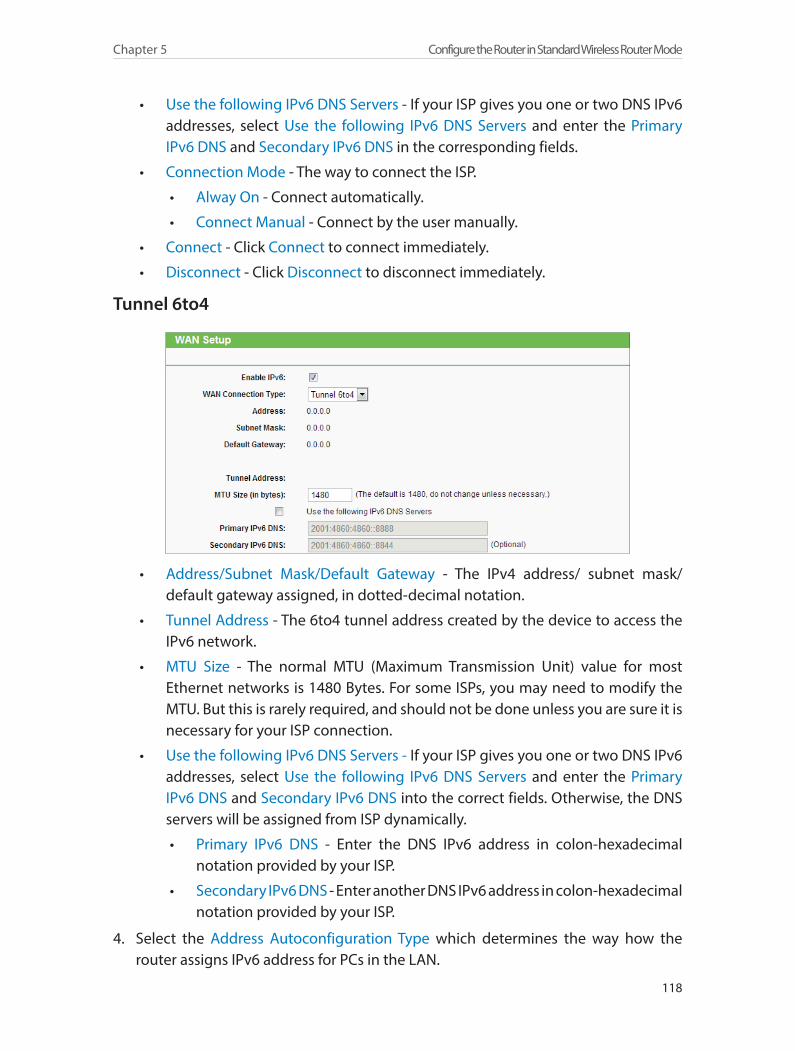
118
Chapter 5 Configure the Router in Standard Wireless Router Mode
• Use the following IPv6 DNS Servers - If your ISP gives you one or two DNS IPv6 addresses, select Use the following IPv6 DNS Servers and enter the Primary IPv6 DNS and Secondary IPv6 DNS in the corresponding fields.
• Connection Mode - The way to connect the ISP.
• Alway On - Connect automatically.
• Connect Manual - Connect by the user manually.
• Connect - Click Connect to connect immediately.
• Disconnect - Click Disconnect to disconnect immediately.
Tunnel 6to4
• Address/Subnet Mask/Default Gateway - The IPv4 address/ subnet mask/ default gateway assigned, in dotted-decimal notation.
• Tunnel Address - The 6to4 tunnel address created by the device to access the IPv6 network.
• MTU Size - The normal MTU (Maximum Transmission Unit) value for most Ethernet networks is 1480 Bytes. For some ISPs, you may need to modify the MTU. But this is rarely required, and should not be done unless you are sure it is necessary for your ISP connection.
• Use the following IPv6 DNS Servers - If your ISP gives you one or two DNS IPv6 addresses, select Use the following IPv6 DNS Servers and enter the Primary IPv6 DNS and Secondary IPv6 DNS into the correct fields. Otherwise, the DNS servers will be assigned from ISP dynamically.
• Primary IPv6 DNS - Enter the DNS IPv6 address in colon-hexadecimal notation provided by your ISP.
• Secondary IPv6 DNS - Enter another DNS IPv6 address in colon-hexadecimal notation provided by your ISP.
4. Select the Address Autoconfiguration Type which determines the way how the router assigns IPv6 address for PCs in the LAN.
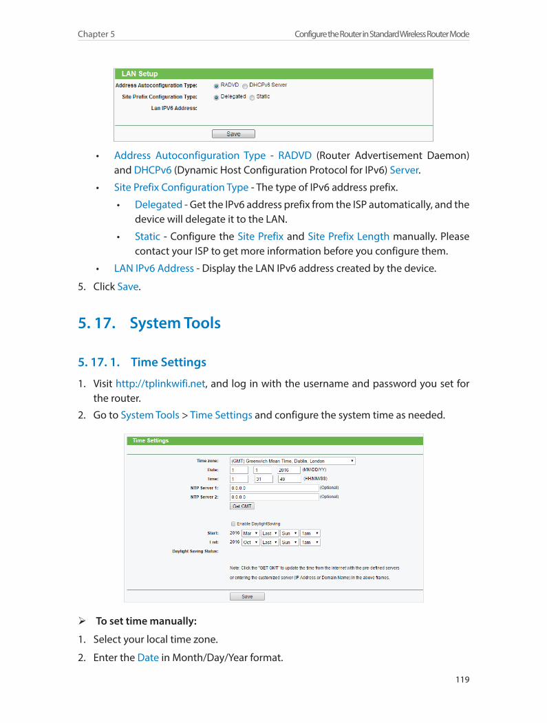
119
Chapter 5 Configure the Router in Standard Wireless Router Mode
• Address Autoconfiguration Type - RADVD (Router Advertisement Daemon) and DHCPv6 (Dynamic Host Configuration Protocol for IPv6) Server.
• Site Prefix Configuration Type - The type of IPv6 address prefix.
• Delegated - Get the IPv6 address prefix from the ISP automatically, and the device will delegate it to the LAN.
• Static - Configure the Site Prefix and Site Prefix Length manually. Please contact your ISP to get more information before you configure them.
• LAN IPv6 Address - Display the LAN IPv6 address created by the device.
5. Click Save.
5. 17. System Tools
5. 17. 1. Time Settings
1. Visit http://tplinkwifi.net, and log in with the username and password you set for the router.
2. Go to System Tools > Time Settings and configure the system time as needed.
¾ To set time manually:
1. Select your local time zone.
2. Enter the Date in Month/Day/Year format.
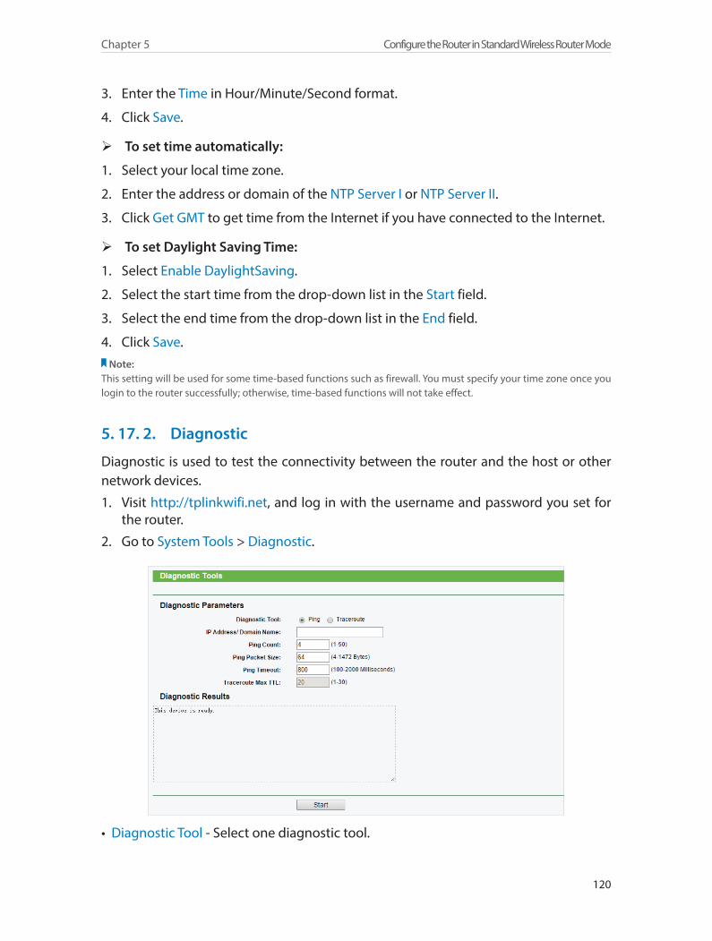
120
Chapter 5 Configure the Router in Standard Wireless Router Mode
3. Enter the Time in Hour/Minute/Second format.
4. Click Save.
¾ To set time automatically:
1. Select your local time zone.
2. Enter the address or domain of the NTP Server I or NTP Server II.
3. Click Get GMT to get time from the Internet if you have connected to the Internet.
¾ To set Daylight Saving Time:
1. Select Enable DaylightSaving.
2. Select the start time from the drop-down list in the Start field.
3. Select the end time from the drop-down list in the End field.
4. Click Save.Note:
This setting will be used for some time-based functions such as firewall. You must specify your time zone once you login to the router successfully; otherwise, time-based functions will not take effect.
5. 17. 2. Diagnostic
Diagnostic is used to test the connectivity between the router and the host or other network devices.
1. Visit http://tplinkwifi.net, and log in with the username and password you set for the router.
2. Go to System Tools > Diagnostic.
• Diagnostic Tool - Select one diagnostic tool.
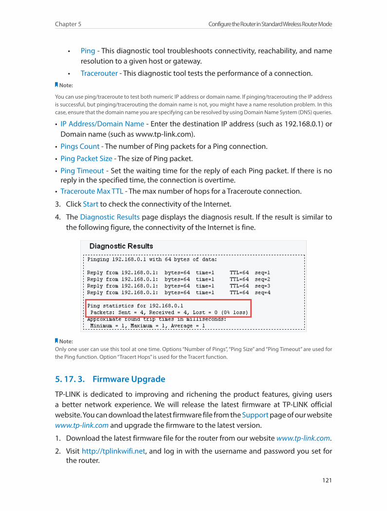
121
Chapter 5 Configure the Router in Standard Wireless Router Mode
• Ping - This diagnostic tool troubleshoots connectivity, reachability, and name resolution to a given host or gateway.
• Tracerouter - This diagnostic tool tests the performance of a connection.Note:
You can use ping/traceroute to test both numeric IP address or domain name. If pinging/tracerouting the IP address is successful, but pinging/tracerouting the domain name is not, you might have a name resolution problem. In this case, ensure that the domain name you are specifying can be resolved by using Domain Name System (DNS) queries.
• IP Address/Domain Name - Enter the destination IP address (such as 192.168.0.1) or Domain name (such as www.tp-link.com).
• Pings Count - The number of Ping packets for a Ping connection.
• Ping Packet Size - The size of Ping packet.
• Ping Timeout - Set the waiting time for the reply of each Ping packet. If there is no reply in the specified time, the connection is overtime.
• Traceroute Max TTL - The max number of hops for a Traceroute connection.
3. Click Start to check the connectivity of the Internet.
4. The Diagnostic Results page displays the diagnosis result. If the result is similar to the following figure, the connectivity of the Internet is fine.
Note: Only one user can use this tool at one time. Options “Number of Pings”, “Ping Size” and “Ping Timeout” are used for the Ping function. Option “Tracert Hops” is used for the Tracert function.
5. 17. 3. Firmware Upgrade
TP-LINK is dedicated to improving and richening the product features, giving users a better network experience. We will release the latest firmware at TP-LINK official website. You can download the latest firmware file from the Support page of our website www.tp-link.com and upgrade the firmware to the latest version.
1. Download the latest firmware file for the router from our website www.tp-link.com.
2. Visit http://tplinkwifi.net, and log in with the username and password you set for the router.
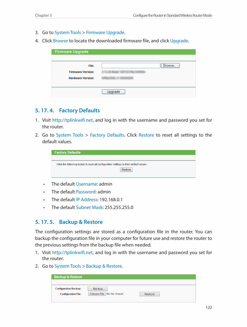
122
Chapter 5 Configure the Router in Standard Wireless Router Mode
3. Go to System Tools > Firmware Upgrade.
4. Click Browse to locate the downloaded firmware file, and click Upgrade.
5. 17. 4. Factory Defaults
1. Visit http://tplinkwifi.net, and log in with the username and password you set for the router.
2. Go to System Tools > Factory Defaults. Click Restore to reset all settings to the default values.
• The default Username: admin
• The default Password: admin
• The default IP Address: 192.168.0.1
• The default Subnet Mask: 255.255.255.0
5. 17. 5. Backup & Restore
The configuration settings are stored as a configuration file in the router. You can backup the configuration file in your computer for future use and restore the router to the previous settings from the backup file when needed.
1. Visit http://tplinkwifi.net, and log in with the username and password you set for the router.
2. Go to System Tools > Backup & Restore.
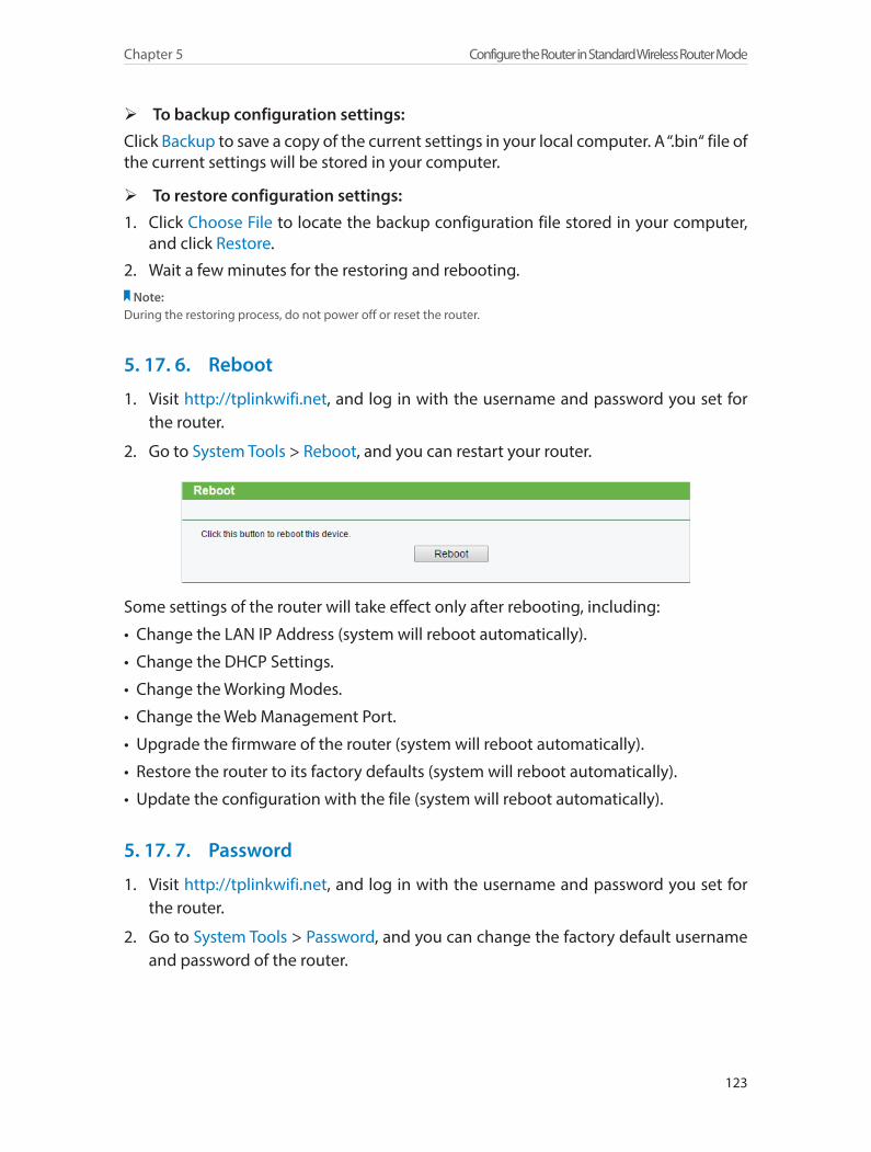
123
Chapter 5 Configure the Router in Standard Wireless Router Mode
¾ To backup configuration settings:
Click Backup to save a copy of the current settings in your local computer. A “.bin“ file of the current settings will be stored in your computer.
¾ To restore configuration settings:
1. Click Choose File to locate the backup configuration file stored in your computer, and click Restore.
2. Wait a few minutes for the restoring and rebooting.Note:
During the restoring process, do not power off or reset the router.
5. 17. 6. Reboot
1. Visit http://tplinkwifi.net, and log in with the username and password you set for the router.
2. Go to System Tools > Reboot, and you can restart your router.
Some settings of the router will take effect only after rebooting, including:
• Change the LAN IP Address (system will reboot automatically).
• Change the DHCP Settings.
• Change the Working Modes.
• Change the Web Management Port.
• Upgrade the firmware of the router (system will reboot automatically).
• Restore the router to its factory defaults (system will reboot automatically).
• Update the configuration with the file (system will reboot automatically).
5. 17. 7. Password
1. Visit http://tplinkwifi.net, and log in with the username and password you set for the router.
2. Go to System Tools > Password, and you can change the factory default username and password of the router.
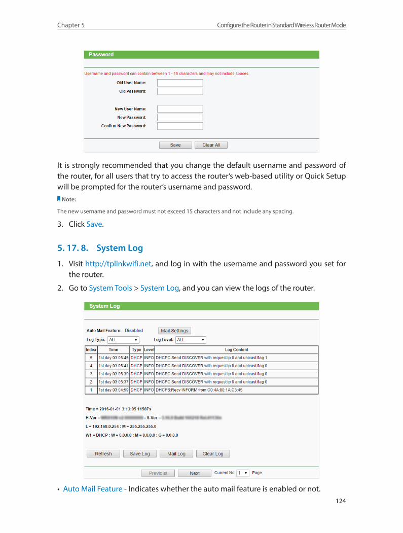
124
Chapter 5 Configure the Router in Standard Wireless Router Mode
It is strongly recommended that you change the default username and password of the router, for all users that try to access the router’s web-based utility or Quick Setup will be prompted for the router’s username and password.
Note:
The new username and password must not exceed 15 characters and not include any spacing.
3. Click Save.
5. 17. 8. System Log
1. Visit http://tplinkwifi.net, and log in with the username and password you set for the router.
2. Go to System Tools > System Log, and you can view the logs of the router.
• Auto Mail Feature - Indicates whether the auto mail feature is enabled or not.
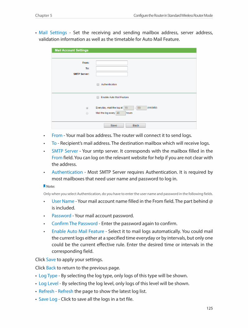
125
Chapter 5 Configure the Router in Standard Wireless Router Mode
• Mail Settings - Set the receiving and sending mailbox address, server address, validation information as well as the timetable for Auto Mail Feature.
• From - Your mail box address. The router will connect it to send logs.
• To - Recipient’s mail address. The destination mailbox which will receive logs.
• SMTP Server - Your smtp server. It corresponds with the mailbox filled in the From field. You can log on the relevant website for help if you are not clear with the address.
• Authentication - Most SMTP Server requires Authentication. It is required by most mailboxes that need user name and password to log in.
Note:
Only when you select Authentication, do you have to enter the user name and password in the following fields.
• User Name - Your mail account name filled in the From field. The part behind @ is included.
• Password - Your mail account password.
• Confirm The Password - Enter the password again to confirm.
• Enable Auto Mail Feature - Select it to mail logs automatically. You could mail the current logs either at a specified time everyday or by intervals, but only one could be the current effective rule. Enter the desired time or intervals in the corresponding field.
Click Save to apply your settings.
Click Back to return to the previous page.
• Log Type - By selecting the log type, only logs of this type will be shown.
• Log Level - By selecting the log level, only logs of this level will be shown.
• Refresh - Refresh the page to show the latest log list.
• Save Log - Click to save all the logs in a txt file.
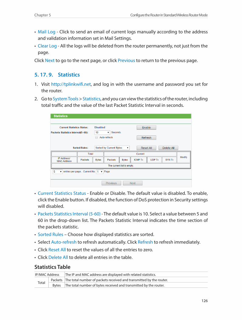
126
Chapter 5 Configure the Router in Standard Wireless Router Mode
• Mail Log - Click to send an email of current logs manually according to the address and validation information set in Mail Settings.
• Clear Log - All the logs will be deleted from the router permanently, not just from the page.
Click Next to go to the next page, or click Previous to return to the previous page.
5. 17. 9. Statistics
1. Visit http://tplinkwifi.net, and log in with the username and password you set for the router.
2. Go to System Tools > Statistics, and you can view the statistics of the router, including total traffic and the value of the last Packet Statistic Interval in seconds.
• Current Statistics Status - Enable or Disable. The default value is disabled. To enable, click the Enable button. If disabled, the function of DoS protection in Security settings will disabled.
• Packets Statistics Interval (5-60) - The default value is 10. Select a value between 5 and 60 in the drop-down list. The Packets Statistic Interval indicates the time section of the packets statistic.
• Sorted Rules – Choose how displayed statistics are sorted.
• Select Auto-refresh to refresh automatically. Click Refresh to refresh immediately.
• Click Reset All to reset the values of all the entries to zero.
• Click Delete All to delete all entries in the table.
Statistics TableIP/MAC Address The IP and MAC address are displayed with related statistics.
TotalPackets The total number of packets received and transmitted by the router.
Bytes The total number of bytes received and transmitted by the router.
127
Chapter 5 Configure the Router in Standard Wireless Router Mode
Current
PacketsThe total number of packets received and transmitted in the last Packets Statistic interval seconds.
Bytes The total number of bytes received and transmitted in the last Packets Statistic interval seconds.
ICMP TxThe number of the ICMP packets transmitted to WAN per second at the specified Packets Statistics interval. It is shown like “current transmitting rate / Max transmitting rate”.
UDP TxThe number of UDP packets transmitted to the WAN per second at the specified Packets Statistics interval. It is shown like “current transmitting rate / Max transmitting rate”.
TCP SYN Tx
The number of TCP SYN packets transmitted to the WAN per second at the specified Packets Statistics interval. It is shown like “current transmitting rate / Max transmitting rate”.
ModifyReset Reset the value of the entry to zero.
Delete Delete the existing entry in the table.
5. 18. LogoutClick Logout at the bottom of the main menu, and you will log out of the web page and return to the login window.

128
Chapter 5 Configure the Router in Standard Wireless Router Mode
Chapter 6
Configure the Router in Repeater Mode
This chapter presents how to configure the various features of the router working as a Repeater.
This chapter contains the following sections:
• Status
• Working Mode
• Network
• Wireless
• DHCP
• System Tools
• Logout
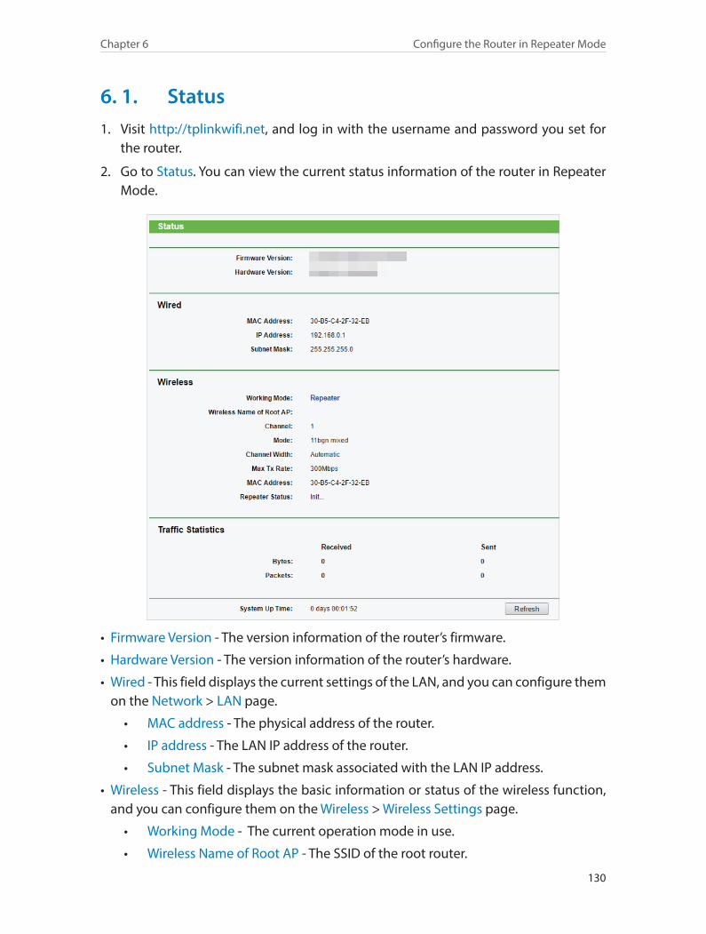
130
Chapter 6 Configure the Router in Repeater Mode
6. 1. Status1. Visit http://tplinkwifi.net, and log in with the username and password you set for
the router.
2. Go to Status. You can view the current status information of the router in Repeater Mode.
• Firmware Version - The version information of the router’s firmware.
• Hardware Version - The version information of the router’s hardware.
• Wired - This field displays the current settings of the LAN, and you can configure them on the Network > LAN page.
• MAC address - The physical address of the router.
• IP address - The LAN IP address of the router.
• Subnet Mask - The subnet mask associated with the LAN IP address.
• Wireless - This field displays the basic information or status of the wireless function, and you can configure them on the Wireless > Wireless Settings page.
• Working Mode - The current operation mode in use.
• Wireless Name of Root AP - The SSID of the root router.
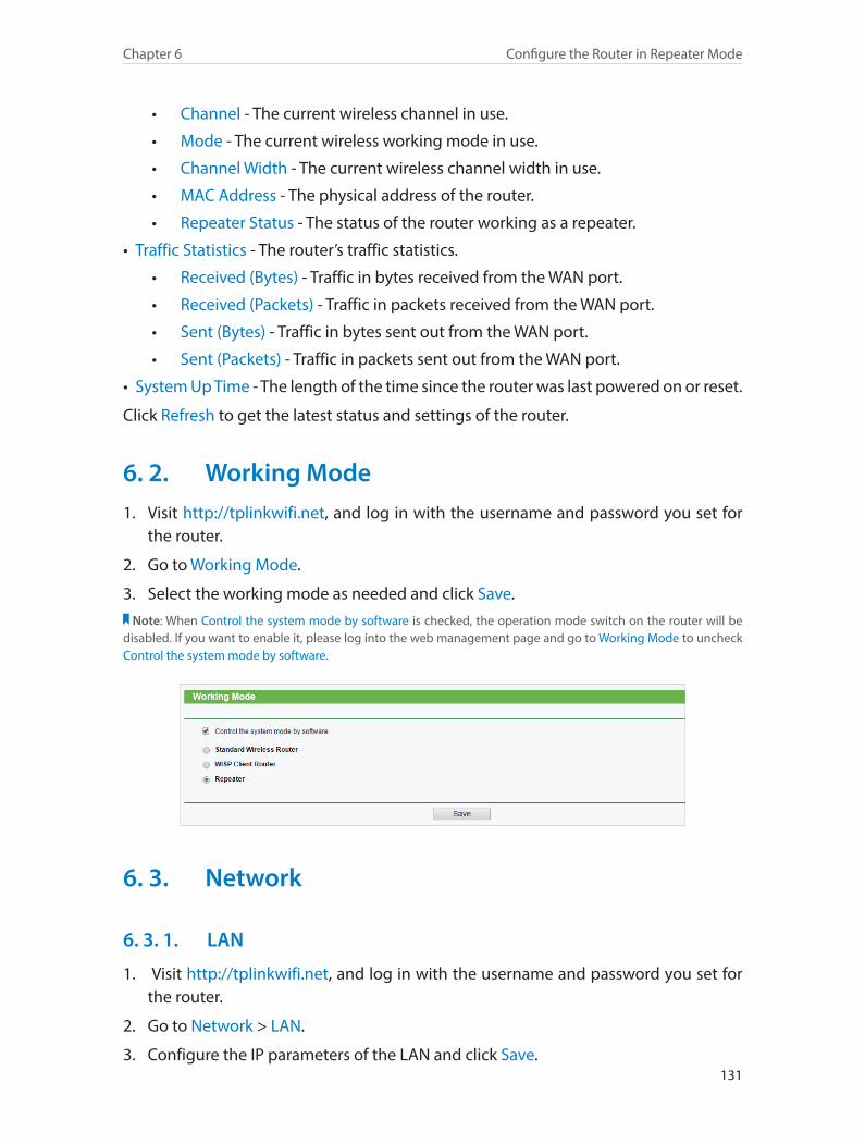
131
Chapter 6 Configure the Router in Repeater Mode
• Channel - The current wireless channel in use.
• Mode - The current wireless working mode in use.
• Channel Width - The current wireless channel width in use.
• MAC Address - The physical address of the router.
• Repeater Status - The status of the router working as a repeater.
• Traffic Statistics - The router’s traffic statistics.
• Received (Bytes) - Traffic in bytes received from the WAN port.
• Received (Packets) - Traffic in packets received from the WAN port.
• Sent (Bytes) - Traffic in bytes sent out from the WAN port.
• Sent (Packets) - Traffic in packets sent out from the WAN port.
• System Up Time - The length of the time since the router was last powered on or reset.
Click Refresh to get the latest status and settings of the router.
6. 2. Working Mode1. Visit http://tplinkwifi.net, and log in with the username and password you set for
the router.
2. Go to Working Mode.
3. Select the working mode as needed and click Save.Note: When Control the system mode by software is checked, the operation mode switch on the router will be
disabled. If you want to enable it, please log into the web management page and go to Working Mode to uncheck Control the system mode by software.
6. 3. Network
6. 3. 1. LAN
1. Visit http://tplinkwifi.net, and log in with the username and password you set for the router.
2. Go to Network > LAN.
3. Configure the IP parameters of the LAN and click Save.
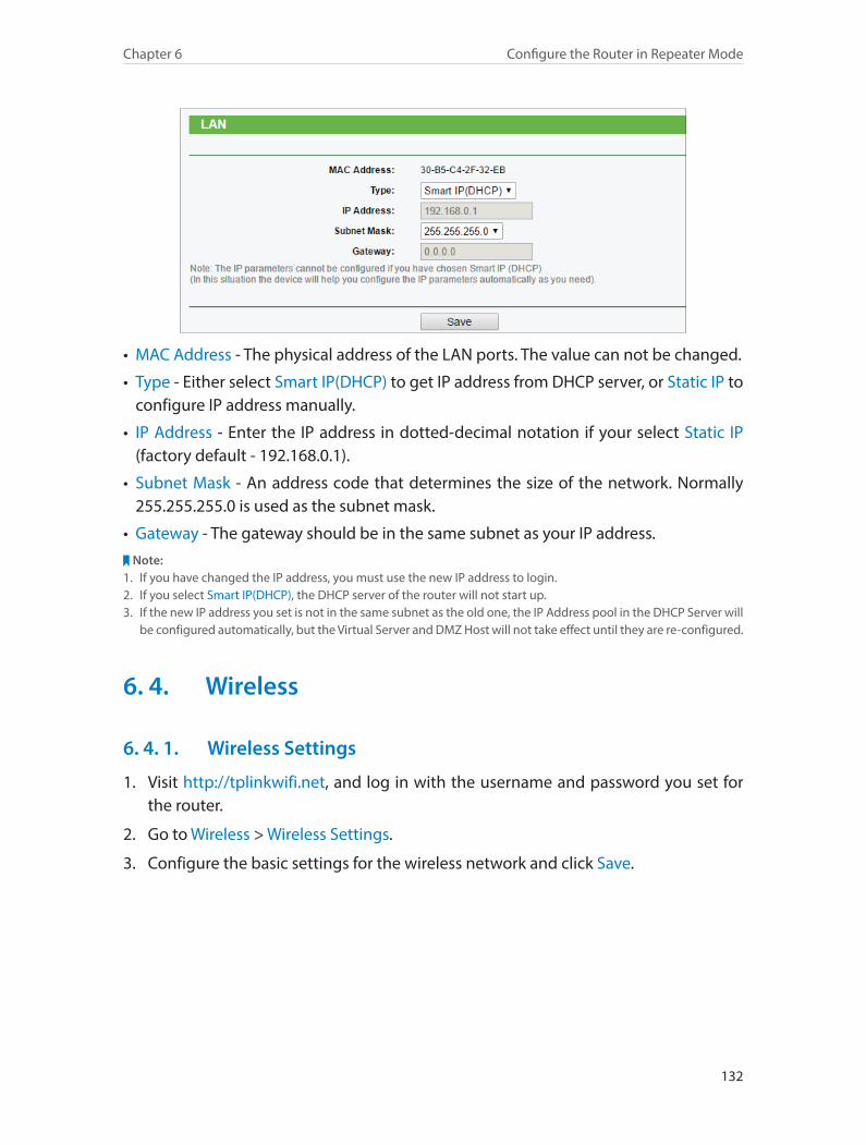
132
Chapter 6 Configure the Router in Repeater Mode
• MAC Address - The physical address of the LAN ports. The value can not be changed.
• Type - Either select Smart IP(DHCP) to get IP address from DHCP server, or Static IP to configure IP address manually.
• IP Address - Enter the IP address in dotted-decimal notation if your select Static IP (factory default - 192.168.0.1).
• Subnet Mask - An address code that determines the size of the network. Normally 255.255.255.0 is used as the subnet mask.
• Gateway - The gateway should be in the same subnet as your IP address.Note:
1. If you have changed the IP address, you must use the new IP address to login.2. If you select Smart IP(DHCP), the DHCP server of the router will not start up.3. If the new IP address you set is not in the same subnet as the old one, the IP Address pool in the DHCP Server will
be configured automatically, but the Virtual Server and DMZ Host will not take effect until they are re-configured.
6. 4. Wireless
6. 4. 1. Wireless Settings
1. Visit http://tplinkwifi.net, and log in with the username and password you set for the router.
2. Go to Wireless > Wireless Settings.
3. Configure the basic settings for the wireless network and click Save.
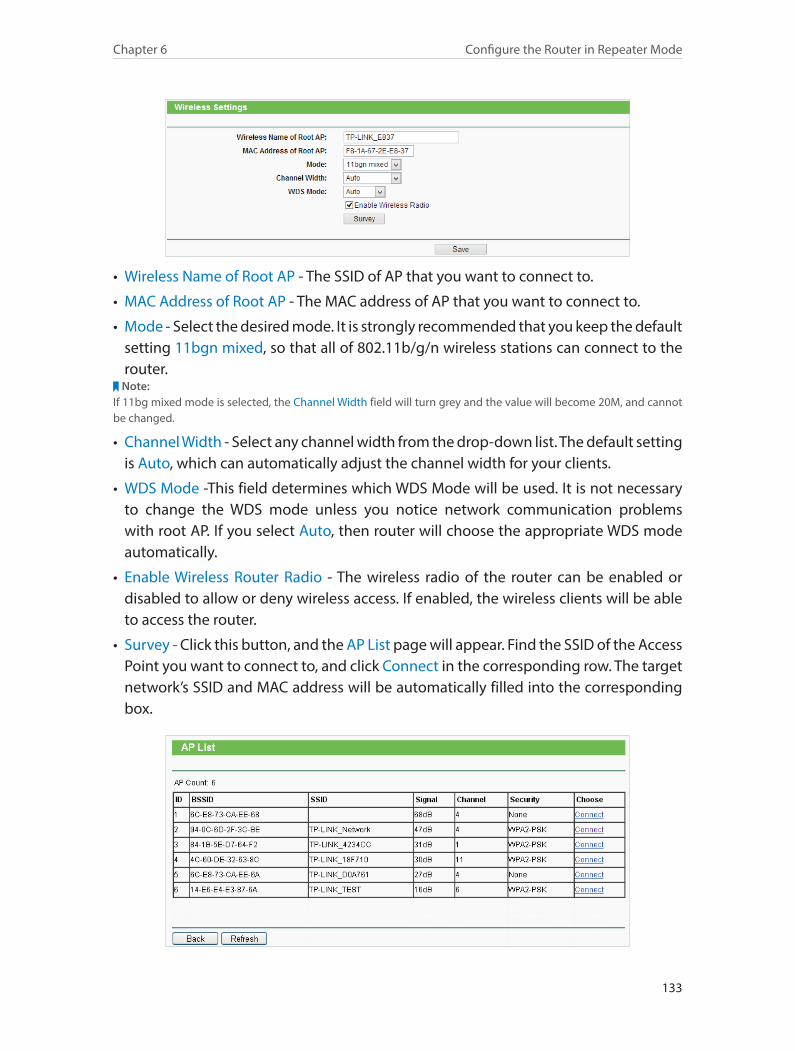
133
Chapter 6 Configure the Router in Repeater Mode
• Wireless Name of Root AP - The SSID of AP that you want to connect to.
• MAC Address of Root AP - The MAC address of AP that you want to connect to.
• Mode - Select the desired mode. It is strongly recommended that you keep the default setting 11bgn mixed, so that all of 802.11b/g/n wireless stations can connect to the router.
Note:If 11bg mixed mode is selected, the Channel Width field will turn grey and the value will become 20M, and cannot be changed.
• Channel Width - Select any channel width from the drop-down list. The default setting is Auto, which can automatically adjust the channel width for your clients.
• WDS Mode -This field determines which WDS Mode will be used. It is not necessary to change the WDS mode unless you notice network communication problems with root AP. If you select Auto, then router will choose the appropriate WDS mode automatically.
• Enable Wireless Router Radio - The wireless radio of the router can be enabled or disabled to allow or deny wireless access. If enabled, the wireless clients will be able to access the router.
• Survey - Click this button, and the AP List page will appear. Find the SSID of the Access Point you want to connect to, and click Connect in the corresponding row. The target network’s SSID and MAC address will be automatically filled into the corresponding box.
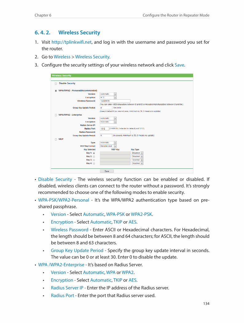
134
Chapter 6 Configure the Router in Repeater Mode
6. 4. 2. Wireless Security
1. Visit http://tplinkwifi.net, and log in with the username and password you set for the router.
2. Go to Wireless > Wireless Security.
3. Configure the security settings of your wireless network and click Save.
• Disable Security - The wireless security function can be enabled or disabled. If disabled, wireless clients can connect to the router without a password. It’s strongly recommended to choose one of the following modes to enable security.
• WPA-PSK/WPA2-Personal - It’s the WPA/WPA2 authentication type based on pre-shared passphrase.
• Version - Select Automatic, WPA-PSK or WPA2-PSK.
• Encryption - Select Automatic, TKIP or AES.
• Wireless Password - Enter ASCII or Hexadecimal characters. For Hexadecimal, the length should be between 8 and 64 characters; for ASCII, the length should be between 8 and 63 characters.
• Group Key Update Period - Specify the group key update interval in seconds. The value can be 0 or at least 30. Enter 0 to disable the update.
• WPA /WPA2-Enterprise - It’s based on Radius Server.
• Version - Select Automatic, WPA or WPA2.
• Encryption - Select Automatic, TKIP or AES.
• Radius Server IP - Enter the IP address of the Radius server.
• Radius Port - Enter the port that Radius server used.
135
Chapter 6 Configure the Router in Repeater Mode
• Radius Password - Enter the password for the Radius server.
• Group Key Update Period - Specify the group key update interval in seconds. The value should be 30 or above. Enter 0 to disable the update.
• WEP - It is based on the IEEE 802.11 standard.
• Type - The default setting is Automatic, which can select Shared Key or Open System authentication type automatically based on the wireless client’s capability and request.
• WEP Key Format - Hexadecimal and ASCII formats are provided here. Hexadecimal format stands for any combination of hexadecimal digits (0-9, a-f, A-F) in the specified length. ASCII format stands for any combination of keyboard characters in the specified length.
• WEP Key (Password) - Select which of the four keys will be used and enter the matching WEP key. Make sure these values are identical on all wireless clients in your network.
• Key Type - Select the WEP key length (64-bit, 128-bit or 152-bit) for encryption. Disabled means this WEP key entry is invalid.
• 64-bit - Enter 10 hexadecimal digits (any combination of 0-9, a-f and A-F. Null key is not permitted) or 5 ASCII characters.
• 128-bit - Enter 26 hexadecimal digits (any combination of 0-9, a-f and A-F. Null key is not permitted) or 13 ASCII characters.
• 152-bit - Enter 32 hexadecimal digits (any combination of 0-9, a-f and A-F. Null key is not permitted) or 16 ASCII characters.
6. 4. 3. Wireless MAC Filtering
Wireless MAC Filtering is used to deny or allow specific wireless client devices to access your network by their MAC addresses.
Deny or allow specific wireless client devices to access my network by their MAC addresses.
For example, you want the wireless client A with the MAC address 00-0A-EB-B0-00-0B and the wireless client B with the MAC address 00-0A-EB-00-07-5F to access the router, but other wireless clients cannot access the router
1. Visit http://tplinkwifi.net, and log in with the username and password you set for the router.
2. Go to Wireless > Wireless MAC Filtering.
3. Click Enable to enable the Wireless MAC Filtering function.
I want to:
How can I do that?
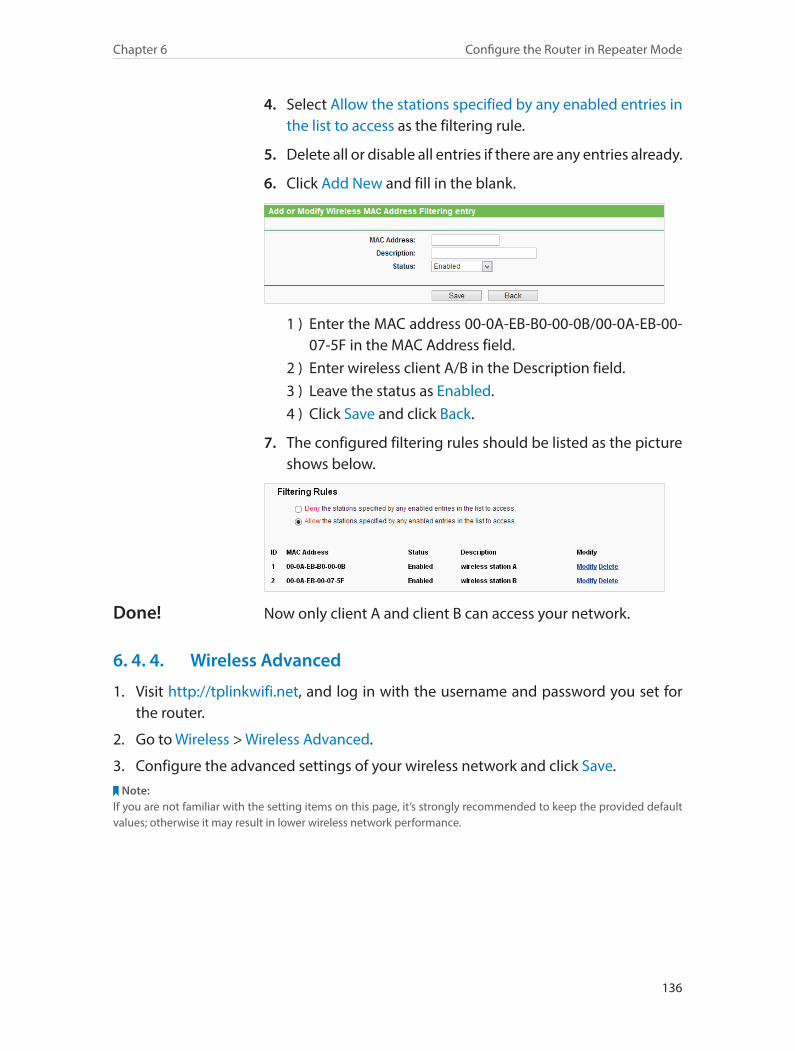
136
Chapter 6 Configure the Router in Repeater Mode
4. Select Allow the stations specified by any enabled entries in the list to access as the filtering rule.
5. Delete all or disable all entries if there are any entries already.
6. Click Add New and fill in the blank.
1 ) Enter the MAC address 00-0A-EB-B0-00-0B/00-0A-EB-00-07-5F in the MAC Address field.
2 ) Enter wireless client A/B in the Description field.3 ) Leave the status as Enabled.4 ) Click Save and click Back.
7. The configured filtering rules should be listed as the picture shows below.
Now only client A and client B can access your network.
6. 4. 4. Wireless Advanced
1. Visit http://tplinkwifi.net, and log in with the username and password you set for the router.
2. Go to Wireless > Wireless Advanced.
3. Configure the advanced settings of your wireless network and click Save.Note:
If you are not familiar with the setting items on this page, it’s strongly recommended to keep the provided default values; otherwise it may result in lower wireless network performance.
Done!
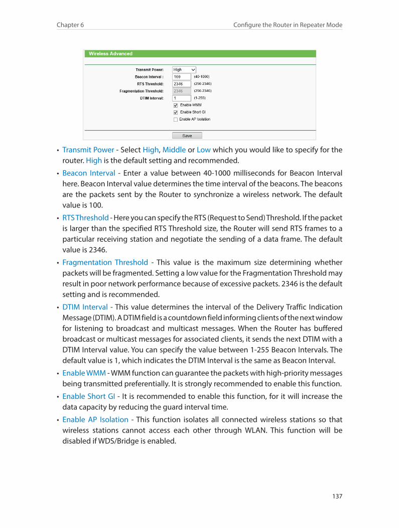
137
Chapter 6 Configure the Router in Repeater Mode
• Transmit Power - Select High, Middle or Low which you would like to specify for the router. High is the default setting and recommended.
• Beacon Interval - Enter a value between 40-1000 milliseconds for Beacon Interval here. Beacon Interval value determines the time interval of the beacons. The beacons are the packets sent by the Router to synchronize a wireless network. The default value is 100.
• RTS Threshold - Here you can specify the RTS (Request to Send) Threshold. If the packet is larger than the specified RTS Threshold size, the Router will send RTS frames to a particular receiving station and negotiate the sending of a data frame. The default value is 2346.
• Fragmentation Threshold - This value is the maximum size determining whether packets will be fragmented. Setting a low value for the Fragmentation Threshold may result in poor network performance because of excessive packets. 2346 is the default setting and is recommended.
• DTIM Interval - This value determines the interval of the Delivery Traffic Indication Message (DTIM). A DTIM field is a countdown field informing clients of the next window for listening to broadcast and multicast messages. When the Router has buffered broadcast or multicast messages for associated clients, it sends the next DTIM with a DTIM Interval value. You can specify the value between 1-255 Beacon Intervals. The default value is 1, which indicates the DTIM Interval is the same as Beacon Interval.
• Enable WMM - WMM function can guarantee the packets with high-priority messages being transmitted preferentially. It is strongly recommended to enable this function.
• Enable Short GI - It is recommended to enable this function, for it will increase the data capacity by reducing the guard interval time.
• Enable AP Isolation - This function isolates all connected wireless stations so that wireless stations cannot access each other through WLAN. This function will be disabled if WDS/Bridge is enabled.
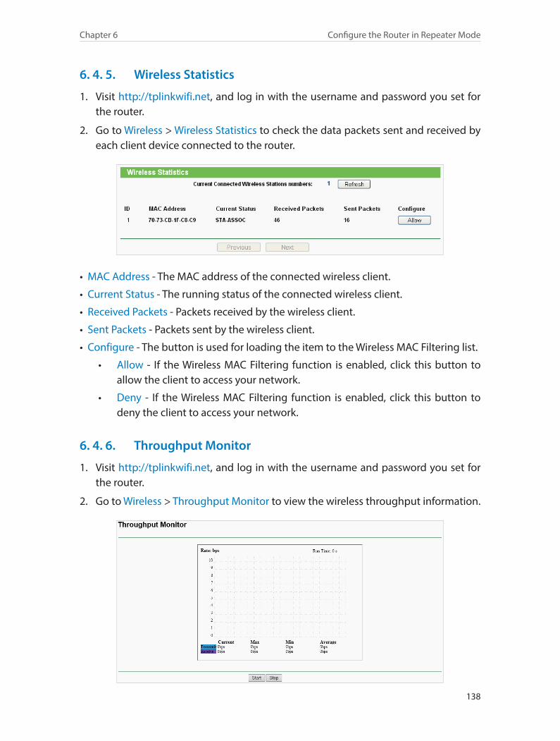
138
Chapter 6 Configure the Router in Repeater Mode
6. 4. 5. Wireless Statistics
1. Visit http://tplinkwifi.net, and log in with the username and password you set for the router.
2. Go to Wireless > Wireless Statistics to check the data packets sent and received by each client device connected to the router.
• MAC Address - The MAC address of the connected wireless client.
• Current Status - The running status of the connected wireless client.
• Received Packets - Packets received by the wireless client.
• Sent Packets - Packets sent by the wireless client.
• Configure - The button is used for loading the item to the Wireless MAC Filtering list.
• Allow - If the Wireless MAC Filtering function is enabled, click this button to allow the client to access your network.
• Deny - If the Wireless MAC Filtering function is enabled, click this button to deny the client to access your network.
6. 4. 6. Throughput Monitor
1. Visit http://tplinkwifi.net, and log in with the username and password you set for the router.
2. Go to Wireless > Throughput Monitor to view the wireless throughput information.
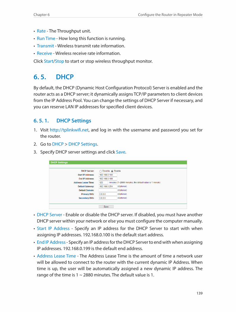
139
Chapter 6 Configure the Router in Repeater Mode
• Rate - The Throughput unit.
• Run Time - How long this function is running.
• Transmit - Wireless transmit rate information.
• Receive - Wireless receive rate information.
Click Start/Stop to start or stop wireless throughput monitor.
6. 5. DHCPBy default, the DHCP (Dynamic Host Configuration Protocol) Server is enabled and the router acts as a DHCP server; it dynamically assigns TCP/IP parameters to client devices from the IP Address Pool. You can change the settings of DHCP Server if necessary, and you can reserve LAN IP addresses for specified client devices.
6. 5. 1. DHCP Settings
1. Visit http://tplinkwifi.net, and log in with the username and password you set for the router.
2. Go to DHCP > DHCP Settings.
3. Specify DHCP server settings and click Save.
• DHCP Server - Enable or disable the DHCP server. If disabled, you must have another DHCP server within your network or else you must configure the computer manually.
• Start IP Address - Specify an IP address for the DHCP Server to start with when assigning IP addresses. 192.168.0.100 is the default start address.
• End IP Address - Specify an IP address for the DHCP Server to end with when assigning IP addresses. 192.168.0.199 is the default end address.
• Address Lease Time - The Address Lease Time is the amount of time a network user will be allowed to connect to the router with the current dynamic IP Address. When time is up, the user will be automatically assigned a new dynamic IP address. The range of the time is 1 ~ 2880 minutes. The default value is 1.
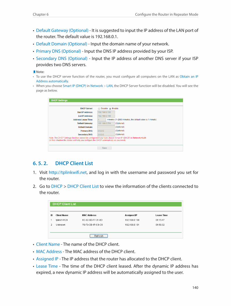
140
Chapter 6 Configure the Router in Repeater Mode
• Default Gateway (Optional) - It is suggested to input the IP address of the LAN port of the router. The default value is 192.168.0.1.
• Default Domain (Optional) - Input the domain name of your network.
• Primary DNS (Optional) - Input the DNS IP address provided by your ISP.
• Secondary DNS (Optional) - Input the IP address of another DNS server if your ISP provides two DNS servers.
Note:• To use the DHCP server function of the router, you must configure all computers on the LAN as Obtain an IP
Address automatically.• When you choose Smart IP (DHCP) in Network > LAN, the DHCP Server function will be disabled. You will see the
page as below.
6. 5. 2. DHCP Client List
1. Visit http://tplinkwifi.net, and log in with the username and password you set for the router.
2. Go to DHCP > DHCP Client List to view the information of the clients connected to the router.
• Client Name - The name of the DHCP client.
• MAC Address - The MAC address of the DHCP client.
• Assigned IP - The IP address that the router has allocated to the DHCP client.
• Lease Time - The time of the DHCP client leased. After the dynamic IP address has expired, a new dynamic IP address will be automatically assigned to the user.
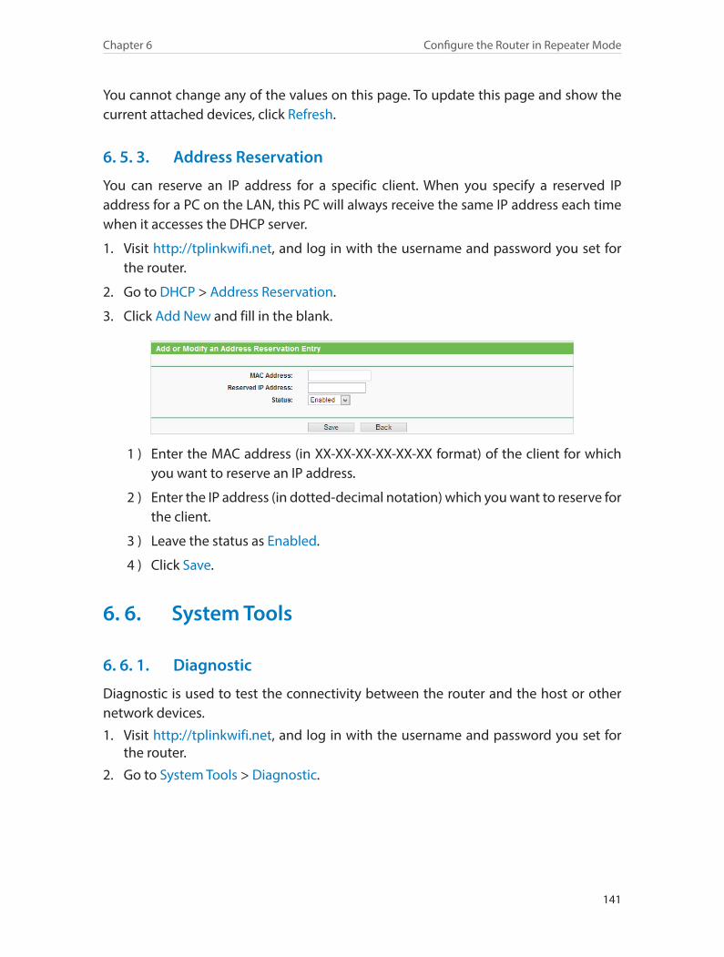
141
Chapter 6 Configure the Router in Repeater Mode
You cannot change any of the values on this page. To update this page and show the current attached devices, click Refresh.
6. 5. 3. Address Reservation
You can reserve an IP address for a specific client. When you specify a reserved IP address for a PC on the LAN, this PC will always receive the same IP address each time when it accesses the DHCP server.
1. Visit http://tplinkwifi.net, and log in with the username and password you set for the router.
2. Go to DHCP > Address Reservation.
3. Click Add New and fill in the blank.
1 ) Enter the MAC address (in XX-XX-XX-XX-XX-XX format) of the client for which you want to reserve an IP address.
2 ) Enter the IP address (in dotted-decimal notation) which you want to reserve for the client.
3 ) Leave the status as Enabled.
4 ) Click Save.
6. 6. System Tools
6. 6. 1. Diagnostic
Diagnostic is used to test the connectivity between the router and the host or other network devices.
1. Visit http://tplinkwifi.net, and log in with the username and password you set for the router.
2. Go to System Tools > Diagnostic.
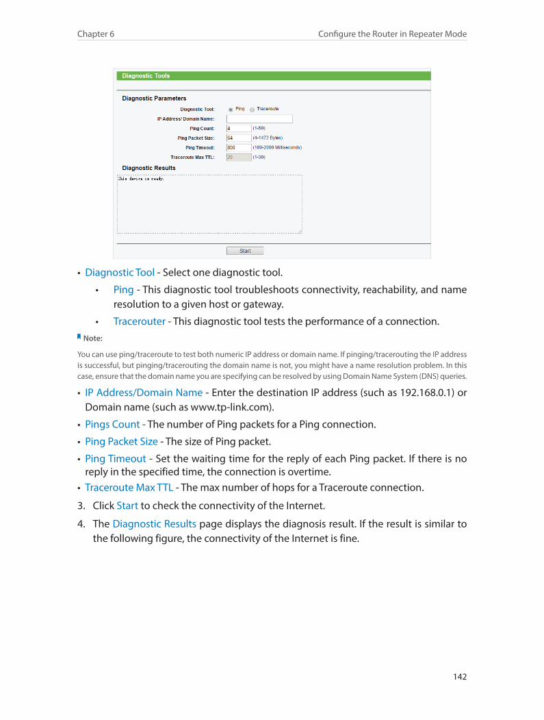
142
Chapter 6 Configure the Router in Repeater Mode
• Diagnostic Tool - Select one diagnostic tool.
• Ping - This diagnostic tool troubleshoots connectivity, reachability, and name resolution to a given host or gateway.
• Tracerouter - This diagnostic tool tests the performance of a connection.Note:
You can use ping/traceroute to test both numeric IP address or domain name. If pinging/tracerouting the IP address is successful, but pinging/tracerouting the domain name is not, you might have a name resolution problem. In this case, ensure that the domain name you are specifying can be resolved by using Domain Name System (DNS) queries.
• IP Address/Domain Name - Enter the destination IP address (such as 192.168.0.1) or Domain name (such as www.tp-link.com).
• Pings Count - The number of Ping packets for a Ping connection.
• Ping Packet Size - The size of Ping packet.
• Ping Timeout - Set the waiting time for the reply of each Ping packet. If there is no reply in the specified time, the connection is overtime.
• Traceroute Max TTL - The max number of hops for a Traceroute connection.
3. Click Start to check the connectivity of the Internet.
4. The Diagnostic Results page displays the diagnosis result. If the result is similar to the following figure, the connectivity of the Internet is fine.
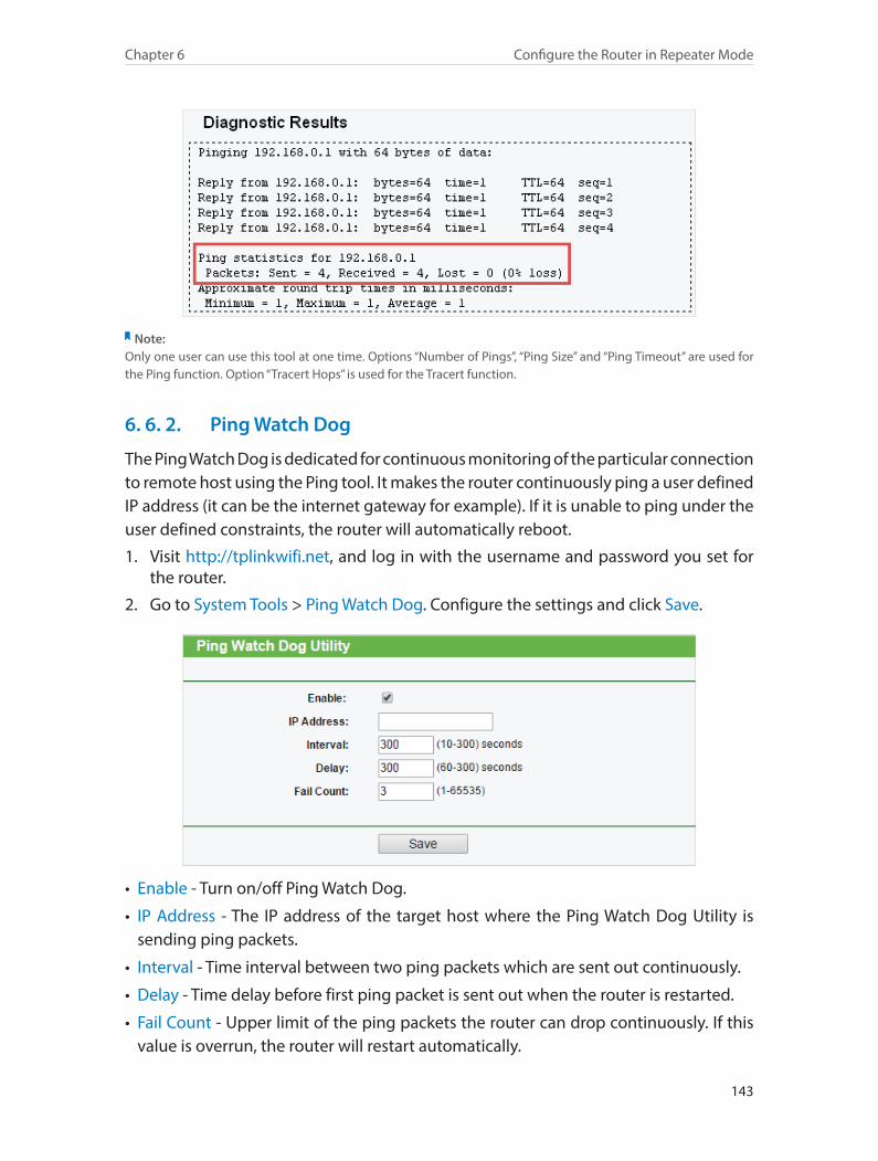
143
Chapter 6 Configure the Router in Repeater Mode
Note: Only one user can use this tool at one time. Options “Number of Pings”, “Ping Size” and “Ping Timeout” are used for the Ping function. Option “Tracert Hops” is used for the Tracert function.
6. 6. 2. Ping Watch Dog
The Ping Watch Dog is dedicated for continuous monitoring of the particular connection to remote host using the Ping tool. It makes the router continuously ping a user defined IP address (it can be the internet gateway for example). If it is unable to ping under the user defined constraints, the router will automatically reboot.
1. Visit http://tplinkwifi.net, and log in with the username and password you set for the router.
2. Go to System Tools > Ping Watch Dog. Configure the settings and click Save.
• Enable - Turn on/off Ping Watch Dog.
• IP Address - The IP address of the target host where the Ping Watch Dog Utility is sending ping packets.
• Interval - Time interval between two ping packets which are sent out continuously.
• Delay - Time delay before first ping packet is sent out when the router is restarted.
• Fail Count - Upper limit of the ping packets the router can drop continuously. If this value is overrun, the router will restart automatically.
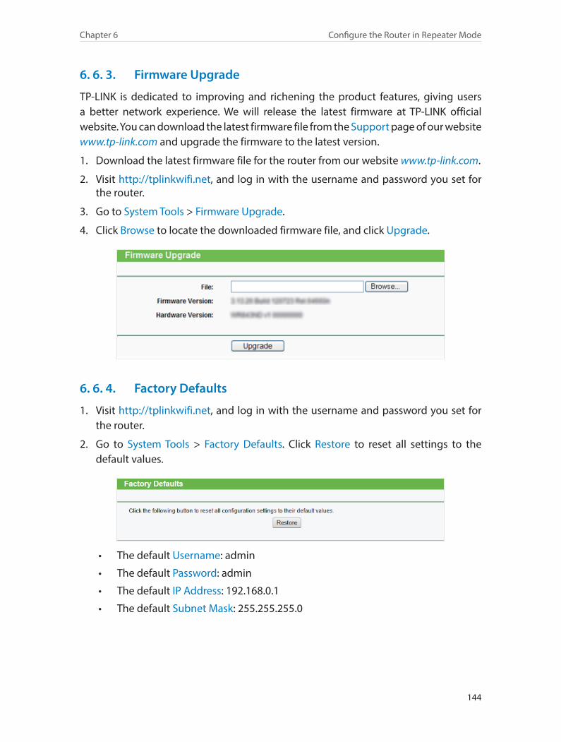
144
Chapter 6 Configure the Router in Repeater Mode
6. 6. 3. Firmware Upgrade
TP-LINK is dedicated to improving and richening the product features, giving users a better network experience. We will release the latest firmware at TP-LINK official website. You can download the latest firmware file from the Support page of our website www.tp-link.com and upgrade the firmware to the latest version.
1. Download the latest firmware file for the router from our website www.tp-link.com.
2. Visit http://tplinkwifi.net, and log in with the username and password you set for the router.
3. Go to System Tools > Firmware Upgrade.
4. Click Browse to locate the downloaded firmware file, and click Upgrade.
6. 6. 4. Factory Defaults
1. Visit http://tplinkwifi.net, and log in with the username and password you set for the router.
2. Go to System Tools > Factory Defaults. Click Restore to reset all settings to the default values.
• The default Username: admin
• The default Password: admin
• The default IP Address: 192.168.0.1
• The default Subnet Mask: 255.255.255.0
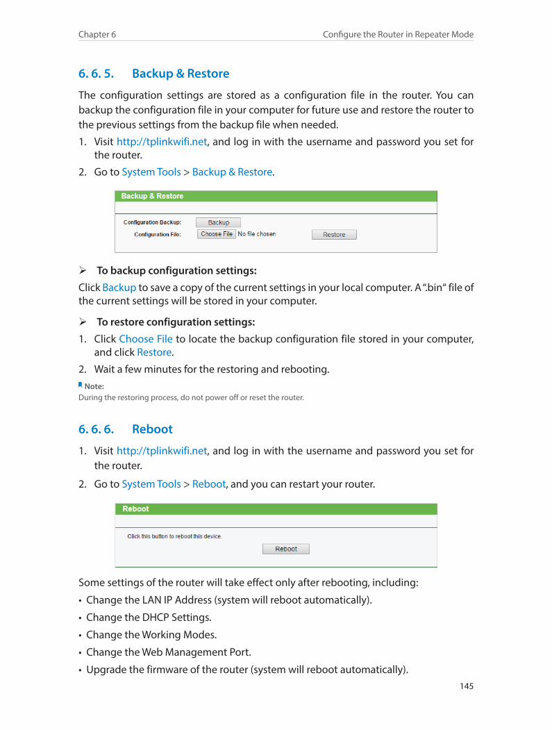
145
Chapter 6 Configure the Router in Repeater Mode
6. 6. 5. Backup & Restore
The configuration settings are stored as a configuration file in the router. You can backup the configuration file in your computer for future use and restore the router to the previous settings from the backup file when needed.
1. Visit http://tplinkwifi.net, and log in with the username and password you set for the router.
2. Go to System Tools > Backup & Restore.
¾ To backup configuration settings:
Click Backup to save a copy of the current settings in your local computer. A “.bin“ file of the current settings will be stored in your computer.
¾ To restore configuration settings:
1. Click Choose File to locate the backup configuration file stored in your computer, and click Restore.
2. Wait a few minutes for the restoring and rebooting.Note:
During the restoring process, do not power off or reset the router.
6. 6. 6. Reboot
1. Visit http://tplinkwifi.net, and log in with the username and password you set for the router.
2. Go to System Tools > Reboot, and you can restart your router.
Some settings of the router will take effect only after rebooting, including:
• Change the LAN IP Address (system will reboot automatically).
• Change the DHCP Settings.
• Change the Working Modes.
• Change the Web Management Port.
• Upgrade the firmware of the router (system will reboot automatically).
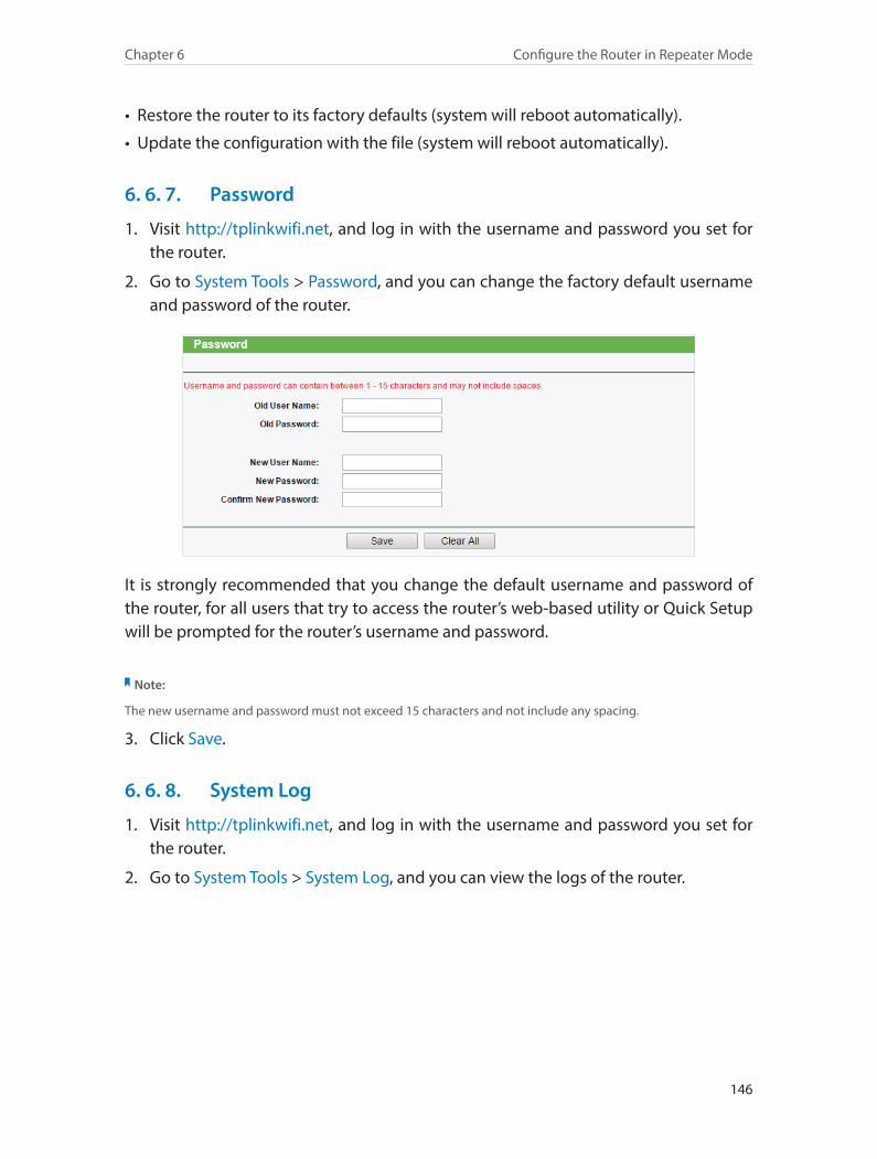
146
Chapter 6 Configure the Router in Repeater Mode
• Restore the router to its factory defaults (system will reboot automatically).
• Update the configuration with the file (system will reboot automatically).
6. 6. 7. Password
1. Visit http://tplinkwifi.net, and log in with the username and password you set for the router.
2. Go to System Tools > Password, and you can change the factory default username and password of the router.
It is strongly recommended that you change the default username and password of the router, for all users that try to access the router’s web-based utility or Quick Setup will be prompted for the router’s username and password.
Note:
The new username and password must not exceed 15 characters and not include any spacing.
3. Click Save.
6. 6. 8. System Log
1. Visit http://tplinkwifi.net, and log in with the username and password you set for the router.
2. Go to System Tools > System Log, and you can view the logs of the router.
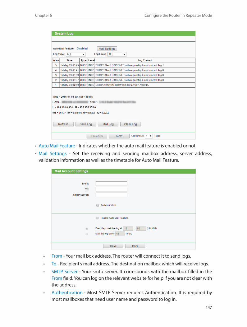
147
Chapter 6 Configure the Router in Repeater Mode
• Auto Mail Feature - Indicates whether the auto mail feature is enabled or not.
• Mail Settings - Set the receiving and sending mailbox address, server address, validation information as well as the timetable for Auto Mail Feature.
• From - Your mail box address. The router will connect it to send logs.
• To - Recipient’s mail address. The destination mailbox which will receive logs.
• SMTP Server - Your smtp server. It corresponds with the mailbox filled in the From field. You can log on the relevant website for help if you are not clear with the address.
• Authentication - Most SMTP Server requires Authentication. It is required by most mailboxes that need user name and password to log in.
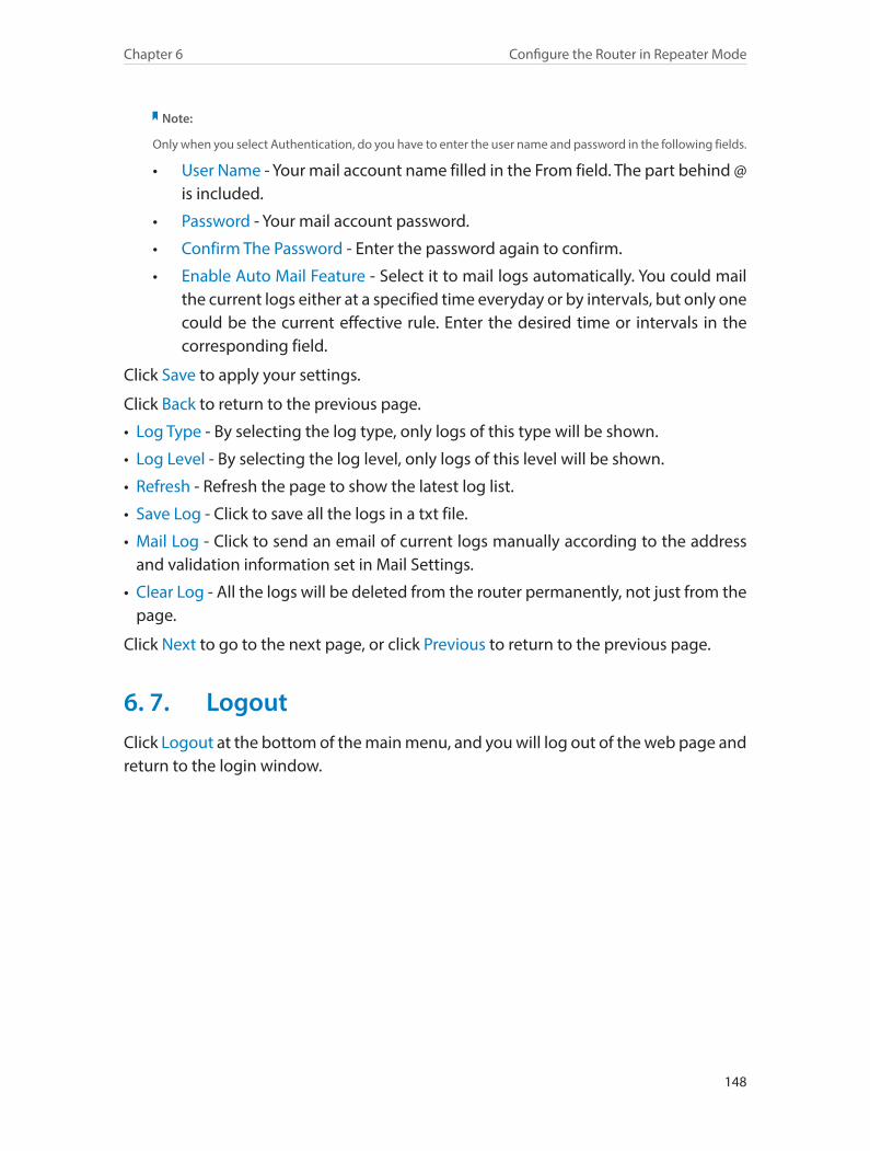
148
Chapter 6 Configure the Router in Repeater Mode
Note:
Only when you select Authentication, do you have to enter the user name and password in the following fields.
• User Name - Your mail account name filled in the From field. The part behind @ is included.
• Password - Your mail account password.
• Confirm The Password - Enter the password again to confirm.
• Enable Auto Mail Feature - Select it to mail logs automatically. You could mail the current logs either at a specified time everyday or by intervals, but only one could be the current effective rule. Enter the desired time or intervals in the corresponding field.
Click Save to apply your settings.
Click Back to return to the previous page.
• Log Type - By selecting the log type, only logs of this type will be shown.
• Log Level - By selecting the log level, only logs of this level will be shown.
• Refresh - Refresh the page to show the latest log list.
• Save Log - Click to save all the logs in a txt file.
• Mail Log - Click to send an email of current logs manually according to the address and validation information set in Mail Settings.
• Clear Log - All the logs will be deleted from the router permanently, not just from the page.
Click Next to go to the next page, or click Previous to return to the previous page.
6. 7. LogoutClick Logout at the bottom of the main menu, and you will log out of the web page and return to the login window.
149
FAQQ1. What can I do if I cannot access the Internet?• If using a cable modem, unplug the Ethernet cable and reboot the modem. Wait until
its Online LED is on and stable, then reconnect the Ethernet cable to the modem.
• If you’re in a hotel room or on a trade show, the Internet may be limited and requires that you authenticate for the service or purchase the Internet access.
• If your Internet access is still not available, contact TP-LINK Technical Support.
Q2. How do I restore the router to its factory default settings?With the router powered on, press and hold the WPS/Reset button for 5 seconds until the Power LED starts flashing and then release the button.
Note: After resetting, all previous configurations will be cleared, and the router will reset to the mode that you have chosen via the operation mode switch.
Q3. What can I do if I forgot my wireless password?• If you have not changed the default Wireless Password, it can be found on the label
of the router.
• Otherwise, connect a computer to the router via an Ethernet cable. Log into the Web Management page, and go to Wireless > Wireless Security to retrieve or reset your wireless password.
Q4. What can I do if I forgot my login password of the web management page?
The default username and password of the web management page are admin (in lowercase). If you have altered the password:
1. Reset the router to factory default settings: With the router powered on, press and hold the WPS/Reset button for 5 seconds until the Power LED starts flashing and then release the button.
2. Visit http://tplinkwifi.net, and enter admin (in lowercase) as both username and password to login.
Note: You’ll need to reconfigure the router to surf the Internet once the router is reset, and please mark down your new password for future use.
Q5. What do I need to do if I want to use NetMeeting?If you start NetMeeting as a sponsor, you don’t need to do anything with the router. If you start as a response, please follow the steps below to configure the router:
1. Visit http://tplinkwifi.net, and log in with the username and password you set for the router.
150
2. Enable DMZ: Go to Forwarding > DMZ. Select Enable and enter your IP address in the DMZ Host IP Address field, and then Click Save.
3. Enable H323 ALG: Go to Security > Basic Security, enable H323 ALG and click Save.
Now you can enjoy your net meeting normally.
Q6. What can I do if my wireless signal is unstable or weak?It may be caused by too much interference.
• Set your wireless channel to a different one.
• Choose a location with less obstacles that may block the signal between the router and the host AP. An open corridor or a spacious location is ideal.
• Move the router to a new location away from Bluetooth devices and other household electronics, such as cordless phone, microwave, and baby monitor, etc., to minimize signal interference.
• When in Repeater mode, the ideal location to place the router is halfway between your host AP and the Wi-Fi dead zone. If that is not possible, place the router closer to your host AP to ensure stable performance.

151
COPYRIGHT & TRADEMARKSSpecifications are subject to change without notice. is a registered trademark of TP-LINK TECHNOLOGIES CO., LTD. Other brands and product names are trademarks or registered trademarks of their respective holders.
No part of the specifications may be reproduced in any form or by any means or used to make any derivative such as translation, transformation, or adaptation without permission from TP-LINK TECHNOLOGIES CO., LTD. Copyright © 2016 TP-LINK TECHNOLOGIES CO., LTD. All rights reserved.
152
FCC STATEMENT
This equipment has been tested and found to comply with the limits for a Class B digital device, pursuant to part 15 of the FCC Rules. These limits are designed to provide reasonable protection against harmful interference in a residential installation. This equipment generates, uses and can radiate radio frequency energy and, if not installed and used in accordance with the instructions, may cause harmful interference to radio communications. However, there is no guarantee that interference will not occur in a particular installation. If this equipment does cause harmful interference to radio or television reception, which can be determined by turning the equipment off and on, the user is encouraged to try to correct the interference by one or more of the following measures:
• Reorient or relocate the receiving antenna.
• Increase the separation between the equipment and receiver.
• Connect the equipment into an outlet on a circuit different from that to which the receiver is connected.
• Consult the dealer or an experienced radio/ TV technician for help.
This device complies with part 15 of the FCC Rules. Operation is subject to the following two conditions:
1. This device may not cause harmful interference.
2. This device must accept any interference received, including interference that may cause undesired operation.
Any changes or modifications not expressly approved by the party responsible for compliance could void the user’s authority to operate the equipment.
Note: The manufacturer is not responsible for any radio or TV interference caused by unauthorized modifications to this equipment. Such modifications could void the user’s authority to operate the equipment.
FCC RF Radiation Exposure StatementThis equipment complies with FCC RF radiation exposure limits set forth for an uncontrolled environment. This device and its antenna must not be co-located or operating in conjunction with any other antenna or transmitter.
“To comply with FCC RF exposure compliance requirements, this grant is applicable to only Mobile Configurations. The antennas used for this transmitter must be installed to provide a separation distance of at least 20 cm from all persons and must not be co-located or operating in conjunction with any other antenna or transmitter.”
153
CE Mark Warning
This is a class B product. In a domestic environment, this product may cause radio interference, in which case the user may be required to take adequate measures.
RF Exposure InformationThis device meets the EU requirements (1999/5/EC Article 3.1a) on the limitation of exposure of the general public to electromagnetic fields by way of health protection.
The device complies with RF specifications when the device used at 20 cm from your body.
Canadian Compliance StatementThis device complies with Industry Canada license-exempt RSSs. Operation is subject to the following two conditions:
1. This device may not cause interference, and
2. This device must accept any interference, including interference that may cause undesired operation of the device.
Le présent appareil est conforme aux CNR d’Industrie Canada applicables aux appareils radio exempts de licence. L’exploitation est autorisée aux deux conditions suivantes:
1. l’appareil ne doit pas produire de brouillage;
2. l’utilisateur de l’appareil doit accepter tout brouillage radioélectrique subi, meme si le brouillage est susceptible d’en compromettre le fonctionnement.
Radiation Exposure Statement:This equipment complies with IC radiation exposure limits set forth for an uncontrolled environment. This equipment should be installed and operated with minimum distance 20cm between the radiator & your body.
Déclaration d’exposition aux radiations:Cet équipement est conforme aux limites d’exposition aux rayonnements IC établies pour un environnement non contrôlé. Cet équipement doit être installé et utilisé avec un minimum de 20 cm de distance entre la source de rayonnement et votre corps.
Industry Canada StatementCAN ICES-3 (B)/NMB-3(B)
Korea Warning Statements당해 무선설비는 운용중 전파혼신 가능성이 있음.
154
NCC Notice
注意! 依據 低功率電波輻射性電機管理辦法
第十二條 經型式認證合格之低功率射頻電機,非經許可,公司、商號或使用者均
不得擅自變更頻率、加大功率或變更原設計之特性或功能。
第十四條 低功率射頻電機之使用不得影響飛航安全及干擾合法通行;經發現有干
擾現象時,應立即停用,並改善至無干擾時方得繼續使用。前項合法通信,指依
電信規定作業之無線電信。低功率射頻電機需忍受合法通信或工業、科學以及醫
療用電波輻射性電機設備之干擾。
BSMI Notice
安全諮詢及注意事項
• 請使用原裝電源供應器或只能按照本產品注明的電源類型使用本產品。
• 清潔本產品之前請先拔掉電源線。請勿使用液體、噴霧清潔劑或濕布進行
清潔。
• 注意防潮,請勿將水或其他液體潑灑到本產品上。
• 插槽與開口供通風使用,以確保本產品的操作可靠並防止過熱,請勿堵塞
或覆蓋開口。
• 請勿將本產品置放於靠近熱源的地方。除非有正常的通風,否則不可放在
密閉位置中。
• 請不要私自打開機殼,不要嘗試自行維修本產品,請由授權的專業人士進
行此項工作。
Продукт сертифіковано згідно с правилами системи УкрСЕПРО на відповідність вимогам нормативних документів та вимогам, що передбачені чинними законодавчими актами України.
Safety Information• When product has power button, the power button is one of the way to shut off the
product; when there is no power button, the only way to completely shut off power is to disconnect the product or the power adapter from the power source.
• Don’t disassemble the product, or make repairs yourself. You run the risk of electric shock and voiding the limited warranty. If you need service, please contact us.
• Avoid water and wet locations.
• Adapter shall be installed near the equipment and shall be easily accessible.
155
• The plug considered as disconnect device of adapter.
• Use only power supplies which are provided by manufacturer and in the original packing of this product. If you have any questions, please don’t hesitate to contact us.
Explanations of the symbols on the product labelSymbol Explanation
DC voltage
RECYCLINGThis product bears the selective sorting symbol for Waste electrical and electronic equipment (WEEE). This means that this product must be handled pursuant to European directive 2012/19/EU in order to be recycled or dismantled to minimize its impact on the environment.User has the choice to give his product to a competent recycling organization or to the retailer when he buys a new electrical or electronic equipment.
Related Documents