Visualize 3D for INVENTOR to Creo View (INVENTOR Adapter) Product Release Version 19.3 USER GUIDE Document Revision: 4.0 Issued: 27/07/2016 © THEOREM SOLUTIONS 2016

Welcome message from author
This document is posted to help you gain knowledge. Please leave a comment to let me know what you think about it! Share it to your friends and learn new things together.
Transcript
Visualize 3D for INVENTOR to Creo View
(INVENTOR Adapter)
Product Release Version 19.3
USER GUIDE Document Revision: 4.0
Issued: 27/07/2016
© THEOREM SOLUTIONS 2016

Visualize 3D v19.3 for INVENTOR to Creo View
1 | Page ©Theorem Solutions 2016
Contents
Overview of Visualize 3D ........................................................................................................... 3
About Theorem ......................................................................................................................3
What is Visualize 3D? .............................................................................................................3
The INVENTOR Creo View Adapter ........................................................................................4
Primary Product Features .......................................................................................................4
Primary Product benefits? ......................................................................................................5
INVENTOR to Creo View Adapter Product Modules ................................................................. 6
Standard Product ....................................................................................................................6
Standard Product for Windchill ..............................................................................................6
Getting Started .......................................................................................................................... 7
Documentation .......................................................................................................................7
Installation Media ...................................................................................................................7
Installation ..............................................................................................................................7
License Configuration .............................................................................................................7
Running the Product ...............................................................................................................7
Using the Product ...................................................................................................................... 9
Translation Configuration ...................................................................................................9
Default Translation .............................................................................................................9
Default Translation – via the Command Line .................................................................9
TheoremOptions – General translation settings (including PMI) ................................ 16
Output Links Option ........................................................................................................ 17
Processing INVENTOR Assemblies (.iam files) ......................................................................... 19
Processing INVENTOR Parts (.ipt files) .................................................................................... 19
Processing INVENTOR Drawings (.idw files) ............................................................................ 19
Efficient Large Assembly Processing ....................................................................................... 20
Error Tracking and Management............................................................................................. 21
Adapter Exit Status Codes ................................................................................................... 21
Summary File Definition ...................................................................................................... 21
Visualize 3D v19.3 for INVENTOR to Creo View
2 | Page ©Theorem Solutions 2016
Summary File Error Codes ................................................................................................... 21
Worker Logs ......................................................................................................................... 22
Process Timeouts ................................................................................................................. 22
Appendix A – Theorem Configuration File .............................................................................. 24
Introduction ......................................................................................................................... 24
Configuration File Format .................................................................................................... 24
Configuration File Location.................................................................................................. 24
Appendix B – Theorem Support Advanced Options ................................................................ 25
Introduction ......................................................................................................................... 25
Diagnostics ........................................................................................................................... 25
Filtering ................................................................................................................................ 25
Options ................................................................................................................................ 25
Restart ................................................................................................................................. 26
Screen Output ..................................................................................................................... 27
Worker Logs ......................................................................................................................... 27
PVZ Output .......................................................................................................................... 27
Issues Creating a INVENTOR Worker ................................................................................... 27
Tessellation Settings ............................................................................................................ 27
Appendix C – Troubleshooting ................................................................................................ 28
Introduction ......................................................................................................................... 28
Check List ............................................................................................................................. 28
Troubleshooting Problem Parts ........................................................................................... 29
Troubleshooting Problem Assemblies ................................................................................. 30
Visualize 3D v19.3 for INVENTOR to Creo View
3 | Page ©Theorem Solutions 2016
Overview of Visualize 3D
About Theorem
Theorem Solutions is a world leader in the field of
Engineering Data Services and Solutions. This
leadership position stems from the quality of our
technology and the people in the company. Quality
comes not only from the skills and commitment of
our staff, but also from the vigorous industrial use of
our technology & services by world leading customers.
We are proud that the vast majority of the world's leading Automotive, Aerospace, Defence,
Power Generation and Transportation companies and their Supply chains use our products
and services daily. Working closely with our customers, to both fully understand their
requirements and feed their input into our development processes has significantly
contributed to our technology and industry knowledge.
Theorem Solutions is an independent UK headquartered company incorporated in 1990,
with sales and support offices in the UK and USA. Theorem has strong relationships with the
major CAD and PLM vendors, including; Autodesk, Dassault Systemes, ICEM Technologies (a
Dassault company), PTC, SolidWorks, Spatial Technology and Siemens PLM Software. These
relationships enable us to deliver best in class services and solutions to engineering
companies worldwide.
What is Visualize 3D?
Visualize 3D is one of 5 core Theorem brands which consist of:
CADverter
Direct translation of 3D data to or from an alternate CAD, Visualization
or Standards Based format
Multi-CAD
Interactive integration of non-native 3D data formats into the native
CAD system
Visualize 3D
Direct translation of 3D data for the purpose of Visualization
Visualize 3D v19.3 for INVENTOR to Creo View
4 | Page ©Theorem Solutions 2016
Publish 3D
The creation of documents enriched with 3D content
Process Automation
Applications to automate any Data Exchange and collaboration
processes
The INVENTOR Creo View Adapter
Theorem’s Visualize 3D product for INVENTOR to Creo View is also known as The INVENTOR Adapter for Creo View. It is a direct data converter from INVENTOR to Creo View, PTC’s visual collaboration product. The Adapter rapidly and accurately publishes 3D mechanical design geometry parts, assemblies and 2D drawings, together with attribute information to the compact formats used by the Creo View application. Designed to be compatible with other PTC Creo View Adapters, the Adapter can be integrated into Windchill, DIVISION Graphics Server or other PDM environments. The AutoDesk Inventor Object Adapter allows the user to translate Inventor assemblies (.iam files) and part (.ipt files) from their original Inventor format into the PTC Creo View .pvs and .ol file formats. In addition to this it also supports the translation of Inventor drawings (.idw files) into DWF format. The adapter is developed using the AutoDesk Apprentice Application Programming Interface (API) and therefore must be installed onto a machine that also has the ability to run an Apprentice API application. Output file characteristics are configured using the standard PTC Recipe File Editor. The Adapter may be installed on a number of machines each accessing a central network-floating license.
Primary Product Features
Converts part geometry including analytic data, solid models, and surfaces to the Creo View “.ol” file format
Converts assembly structure and part orientations to the Creo View “.pvs” file format
Converts attribute data such as meta-data, colour and layer information and INVENTOR properties
Retains accuracy of data in Creo View allowing accurate measurements, sections etc.

Visualize 3D v19.3 for INVENTOR to Creo View
5 | Page ©Theorem Solutions 2016
Configuration compatible with other PTC Creo View Adapters
Optional integration with Windchill, DIVISION Graphics Server as a standard “Worker” application. Also able to be integrated with other PDM environments
Operates in both command-line and batch modes
Configurable to output earlier versions of Creo View data
The Creo View data created using this Adapter can be imported into the Arbortext IsoDraw CADprocess
Primary Product benefits?
Direct conversion from INVENTOR to Creo View reduces processing time, simplifies integration and retains accuracy of the model
Improved communication and collaboration by visualizing INVENTOR data in Creo View across the enterprise
Reduce costs and risks associated to accessing the wrong version of data by integrating the publishing process into all related business processes
With over 20 years industrial use Theorem’s product robustness and quality is well proven, reducing your business risk

Visualize 3D v19.3 for INVENTOR to Creo View
6 | Page ©Theorem Solutions 2016
INVENTOR to Creo View Adapter Product Modules
The following product modules are available for the Creo View Adapter:
Standard Product The standard product functionality is detailed in this user guide and is available for use in a
batch environments.
Standard Product for Windchill The standard product for Windchill functionality is detailed in this user guide and is available
for use in a batch and Windchill environments.
Visualize 3D v19.3 for INVENTOR to Creo View
7 | Page ©Theorem Solutions 2016
Getting Started
Documentation The latest copy of this documentation can be found on our web site at:
http://www.theorem.com/Documentation
Each product has a specific link that provides user documentation in the form of PDF and
Tutorials videos.
Installation Media The latest copy of Theorem software can be found via our web site at:
http://www.theorem.com/Product-Release-Notes
Each product has a specific link to the Product Release Document, which contains a link to
the download location of the installation CD.
Alternatively, you can request a copy of the software to be shipped on a physical CD.
Installation The installation is run from the CD or ZIP file download provided.
To install the translator, select the Setup.exe file and follow the installation
process. For a full guide to the process, please see our ‘Translator Installation
Process’ demonstration video located here.
License Configuration In order for the translation to run successfully, the Theorem license file
provided to you needs to be configured using FlexLM. For a full guide to this
process, please see our ‘FlexLM License Set Up and Configuration’
demonstration video located here.

Visualize 3D v19.3 for INVENTOR to Creo View
8 | Page ©Theorem Solutions 2016
Running the Product Once configured and licensed, the product is ready to be run.
Running the translator via the Command Line:-
The Command Line Interface provides a direct method of invoking the
translator. It can be used directly on the command line or called via a third party
application as part of a wider process requirement. Full compatibility with PTC’s
Windchill Visualization Service (WVS) is supported and is detailed in PTC’s
Windchill Installation and Configuration Guide Inventor_Creo View.
Visualize 3D v19.3 for INVENTOR to Creo View
9 | Page ©Theorem Solutions 2016
Using the Product
Translation Configuration
It is recommended that the INVENTOR to Creo View Adapter be run from a pre-created
configuration. Theorem have adopted the standard PTC Configuration tools which will
create a batch script for running the Adapter on the command line and also a worker
script to allow the Adapter to be run with Windchill.
To take full advantage of the configuration tools and to configure the Adapter for use as
a Windchill Worker please contact your PTC representative to provide the Windchill
Installation and Configuration Guide Inventor Creo View.
Default Translation
Default Translation – via the Command Line Running a translation via the command line can be carried out without using a pre-created
configuration. This will use the default translator settings. This is achieved by directly
running the script file located in the <installation_directory>\bin directory. The format of
the command is as follows:
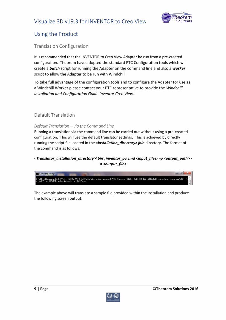
<Translator_installation_directory>\bin\ inventor_pv.cmd <input_files> -p <output_path> -
o <output_file>
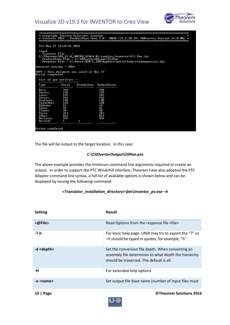
The example above will translate a sample file provided within the installation and produce
the following screen output:
Visualize 3D v19.3 for INVENTOR to Creo View
10 | Page ©Theorem Solutions 2016
The file will be output to the target location. In this case:
C:\CADverterOutput\OilPan.pvs
The above example provides the minimum command line arguments required to create an
output. In order to support the PTC Windchill interface, Theorem have also adopted the PTC
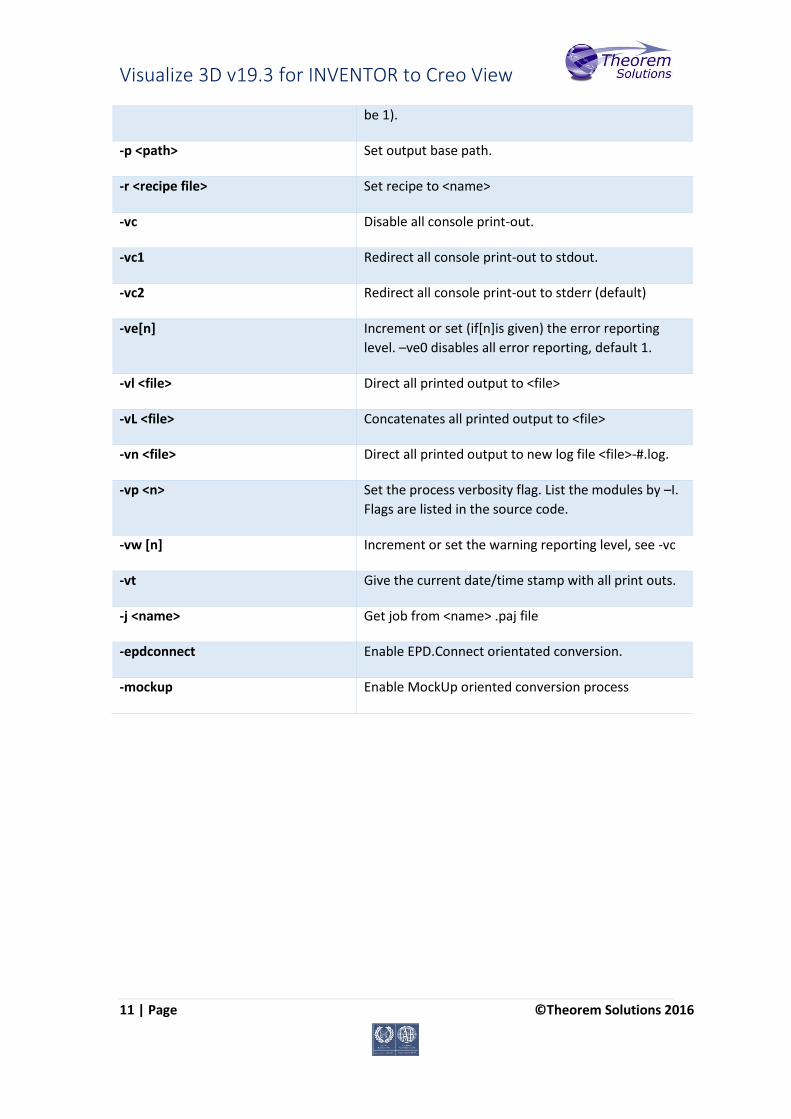
Adapter command line syntax, a full list of available options is shown below and can be
displayed by issuing the following command:
<Translator_installation_directory>\bin\inventor_pv.exe –h
Setting Result
<@File> Read Options from the response file <file>
-?-h For basic help page. UNIX may try to export the “?” so
–h should be typed in quotes, for example, “h”.
-d <depth> Set the conversion file depth. When converting an
assembly file determines to what depth the hierarchy
should be traversed. The default is all.
-H For extended help options
-o <name> Set output file base name (number of input files must
Visualize 3D v19.3 for INVENTOR to Creo View
11 | Page ©Theorem Solutions 2016
be 1).
-p <path> Set output base path.
-r <recipe file> Set recipe to <name>
-vc Disable all console print-out.
-vc1 Redirect all console print-out to stdout.
-vc2 Redirect all console print-out to stderr (default)
-ve[n] Increment or set (if[n]is given) the error reporting
level. –ve0 disables all error reporting, default 1.
-vl <file> Direct all printed output to <file>
-vL <file> Concatenates all printed output to <file>
-vn <file> Direct all printed output to new log file <file>-#.log.
-vp <n> Set the process verbosity flag. List the modules by –I.
Flags are listed in the source code.
-vw [n] Increment or set the warning reporting level, see -vc
-vt Give the current date/time stamp with all print outs.
-j <name> Get job from <name> .paj file
-epdconnect Enable EPD.Connect orientated conversion.
-mockup Enable MockUp oriented conversion process

Visualize 3D v19.3 for INVENTOR to Creo View
12 | Page ©Theorem Solutions 2016
Configuring the INVENTOR Creo View Adapter using the Recipe Editor For completeness this section of the User Guide describes the available configuration
options provided by the recipe editor.
A recipe is a set of user-defined rules that drive the individual CAD Adapter. The recipe
concept provides a solution to the problem of efficiently converting CAD data into a form
suitable for viewing on a wide range of computer platforms. Like its analogy in cooking,
gaining a desired result requires cooking to a specific recipe. While most CAD parts will
convert into an efficient form for large-scale visualization, some parts require modifications
to the standard visualization recipe to be viewed effectively.
The INVENTOR Adapter is provided with a master or default recipe file. This file is pre-
configured to allow the visualization of most objects. The master recipe file should not be
edited. Instead, additional new recipes can be created from this default file using Save As
function in the recipe editor (rcpedit) provided with the translator.
For full details concerning the Recipe Editor, please refer to the ‘Creo View MCAD Adapters
Installation and Configuration Guide’ document, which can be obtained via the PTC
Reference Documents Site at https://www.ptc.com/appserver/cs/doc/refdoc.jsp.
Theorem’s Creo View Adapters use the standard PTC mechanism to Configure translation
options. The basic concepts and available options are covered here for convenience.
Theorem provide a configuration script to allow a recipe file to be created. Running the
following script will launch the Recipe Editor Configuration Tool:
<Translator_installation_directory>\bin\inventor_pv_config.cmd
The panel below will be displayed:

Visualize 3D v19.3 for INVENTOR to Creo View
13 | Page ©Theorem Solutions 2016
The Configuration Tool allows the INVENTOR Creo View Adapter to be configured for use in
batch (via the command line) and/or for use in a Windchill environment (inventorworker).
Please contact your PTC representative to provide the Windchill Installation and
Configuration Guide INVENTOR_Creo View for full details on configuring in a Windchill
environment. This guide will focus on running the translator from the command line, but all
of the configuration options are available in both environments.
The ‘Create inventorbatch’ selection will create a recipe file for batch and the ‘Create
inventorworker’ will create a recipe file for a Windchill invocation. Having selected either of
these options (and provided a valid Windchill Host and Port) the ‘Setup’ button will become
active. Selection of the ‘Setup’ button will launch the following panel:
Visualize 3D v19.3 for INVENTOR to Creo View
14 | Page ©Theorem Solutions 2016
This can be accepted and the ‘Recipe Editor’ button will become active.
The ‘Setup’ action will create a new directory beneath the translator installation directory.
So, the user that creates new configurations will need write access to the translator
installation directory. The first configuration directory will be named inventor_setup.
Subsequent configurations will be named inventor_setup[n] (where ‘n’ is a unique number).
In this manner many different configurations can be created. The configuration directory will
contain an invocation script that will deliver a default Configuration that uses default
translation settings. Selection of the ‘Recipe Editor’ button will allow the user to set specific
translation settings.
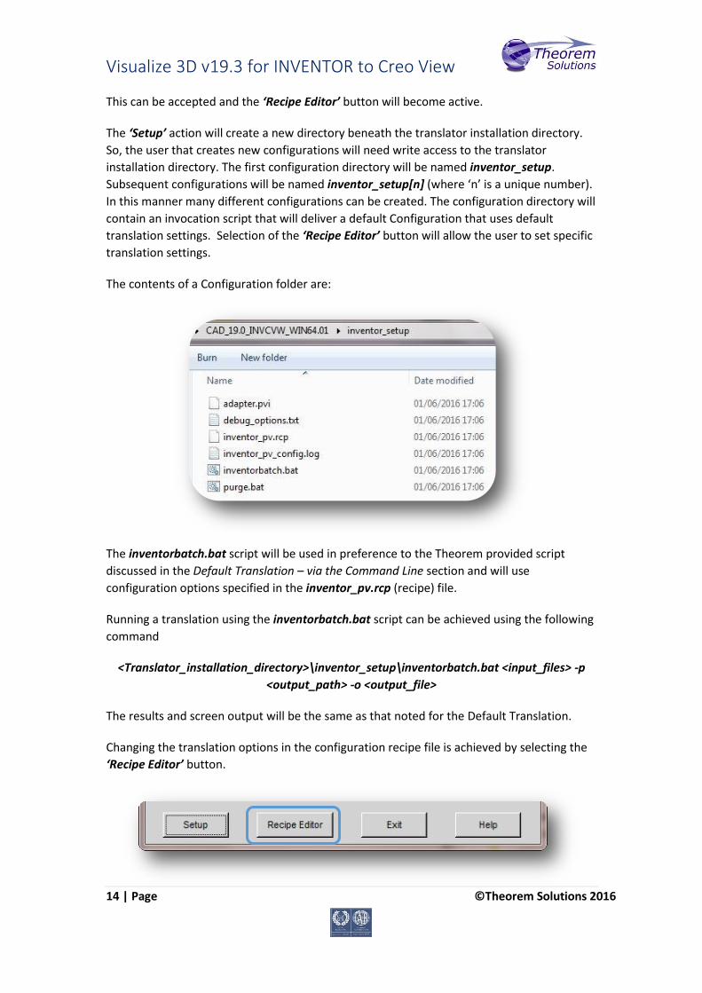
The contents of a Configuration folder are:
The inventorbatch.bat script will be used in preference to the Theorem provided script
discussed in the Default Translation – via the Command Line section and will use
configuration options specified in the inventor_pv.rcp (recipe) file.
Running a translation using the inventorbatch.bat script can be achieved using the following
command
<Translator_installation_directory>\inventor_setup\inventorbatch.bat <input_files> -p
<output_path> -o <output_file>
The results and screen output will be the same as that noted for the Default Translation.
Changing the translation options in the configuration recipe file is achieved by selecting the
‘Recipe Editor’ button.
Visualize 3D v19.3 for INVENTOR to Creo View
15 | Page ©Theorem Solutions 2016
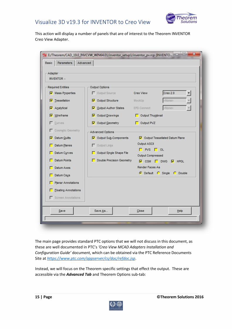
This action will display a number of panels that are of interest to the Theorem INVENTOR
Creo View Adapter.
The main page provides standard PTC options that we will not discuss in this document, as
these are well documented in PTC’s ‘Creo View MCAD Adapters Installation and
Configuration Guide’ document, which can be obtained via the PTC Reference Documents
Site at https://www.ptc.com/appserver/cs/doc/refdoc.jsp.
Instead, we will focus on the Theorem specific settings that effect the output. These are
accessible via the Advanced Tab and Theorem Options sub-tab:

Visualize 3D v19.3 for INVENTOR to Creo View
16 | Page ©Theorem Solutions 2016
Theorem Options – General translation settings
Each of these options is described below:
Option Description
Conversion Mode The user has the option to process Assembly information in
one of 2 modes:
Standard
Minimum Memory
Standard: The default method for assembly processing reads
an INVENTOR assembly and its entire geometry contents
into memory, before writing out all of the data to Creo View.
Minimum Memory: A more efficient way of processing the
data has been provided via the Minimum Memory
conversion mode selection. This mechanism reads in the
assembly data then processes each “.ipt” file referenced by
the assembly on a part by part basis.
Re
ad
Cu
rves
Use 3D Curves This option allows Creo View API to generate its own 2D
curves. This option is most likely only ever used as a work-
around when poor data is encountered.

Visualize 3D v19.3 for INVENTOR to Creo View
17 | Page ©Theorem Solutions 2016
Check 3D Curves This option allows the Adapter to test the data and if
necessary automatically enable Use 3D Curves. A default
tolerance of 0.01 (1%) face/surface overlap being used for
these checks. This tolerance can be adjusted with
validate_3D_curve_tol <value> in the additional option
field.
Dia
gno
stic
Logs
Info Generate a more verbose log files
Wri
te
Op
tio
ns
Instance Attributes This option enables the writing of any instance attributes.
Inve
nto
r D
ata
Mig
rati
on
Ignore Migration This option allows the check for data migration to be omitted.
Pro
ject
File
File Name This allows the user to specify an Inventor project file (*.ipg) which details search paths for parts within an assembly amongst other Inventor settings.
Ad
dit
ion
al
Op
tio
ns
Options This allows the user to specify any advanced options that are not given here by default. Generally these are used for Support purposes.
Ad
dit
ion
al
Op
tio
ns
File
File Name This allows the user to specify a text file that contains a number of advanced options listed line by line.
Output Links Option
This option allows the user to producing a .pvs/.ed File per Node.

Visualize 3D v19.3 for INVENTOR to Creo View
18 | Page ©Theorem Solutions 2016
Some users find it beneficial to generate a .pvs or .ed node for every level in an assembly.
This allows Creo View to load assembly detail from a sub-root level and also allows parts and
assemblies to be processed independently from the top level assembly.
To invoke this functionality launch the recipe editor, as described in the section for
Minimum Memory Mode, see Fig 1 above. Set the Output Links, this will enable the facility
to create individual “.pvs” files for each node. In addition setting the Auto-Load Links option
will create the output files such that the Creo View applications automatically loads the files
on opening, without this setting the user would need to select each file to be loaded
following the initial file open.
Visualize 3D v19.3 for INVENTOR to Creo View
19 | Page ©Theorem Solutions 2016
Processing INVENTOR Assemblies (.iam files)
Assuming that the input to the Adapter was a single assembly named test_assembly.iam related to many subordinate parts (.ipt) files then the output from the translator will be a single Creo View assembly file test_assembly.pvs plus many geometry .ol files, one for each part file processed. Given that the example assembly file had additional assembly files subordinate to it then all of the accumulated assembly hierarchy information would be output into the top level Creo View .pvs file. The INVENTOR Creo View Adapter takes advantage of the latest Creo View dAPI which writes .pvs files (Creo View binary assembly structure files) by default. If a user wishes to write out earlier .pvs versions or .ol files, this can be achieved via the appropriate setting the recipe editor.
Processing INVENTOR Parts (.ipt files)
For each part (.ipt) file processed individually then the output from the translator will be a single Creo View assembly .pvs file and a single geometry .ol file. Therefore assuming that the file being processed was named test_component.ipt then the output would be test_component.pvs and test_component.ol
Processing INVENTOR Drawings (.idw files)
For each drawing (.idw) file processed individually the translator will output a (by default) DXF (.dxf) file per sheet found in the .idw file. The final output to the user is a Creo View assembly file and one or many .dxf format files. Therefore, assuming that the file being processed was named test.idw then the output would be test.pvs and test_sheet1.dxf, test_sheet2.dxf, etc. The user can alternatively elect to output drawing files in either CGM, HPGL, PDF or TIF formats. This can be selected via the recipe editor.

Visualize 3D v19.3 for INVENTOR to Creo View
20 | Page ©Theorem Solutions 2016
Efficient Large Assembly Processing
If an assembly is opened using the INVENTOR, all subordinate assembly and all related geometry will be loaded into memory. This is very inefficient in terms of memory usage. Theorem have made improvements to assembly read efficiency in the following areas:
• Each .ol file is now written and all associated memory freed on a file by file basis, such that in writing to Creo View there is no build-up of memory. • Although the translation process is constrained by the INVENTOR API reading all assembly and geometry information into memory, it is now possible to write out each geometry and assembly file on a file by file basis. This functionality can be invoked by either selecting the “minimum memory” conversion mode option.
The combination of the 2 efficiency improvements detailed here provides in excess of a 20% memory saving on larger (>50MB) assemblies. In general the larger the input assembly the greater the saving will be.
Visualize 3D v19.3 for INVENTOR to Creo View
21 | Page ©Theorem Solutions 2016
Error Tracking and Management
A method of tracking and managing errors output from the INVENTOR to Creo View process
has been provided. This is implemented by setting exit status codes from the Adapter and
additionally the creation of a summary file for each translation task. The structure of the
summary file enables detailed analysis of the translation task to be verified.
Adapter Exit Status Codes The software will return one of the following exit status codes:
0 = Translation completion without errors 1 = Translation completed with errors
These codes will be returned regardless of the type of data being processed, either single parts or assemblies. If the error code returned is 1 (e.g. Completed with errors) the user will be directed to look at a summary file that details the exact reason for failure.
Summary File Definition Each translation creates a summary file using the standard name “tscsummarywj” located in the temporary directory. The user can override the default name using the environment variable TSC_SUMMARY_FILE. The name of the active summary file is recorded in the progress file:
WINDOWS default name=%TEMP%\tscsummary Output is recorded in the summary file with a single line reporting a status for each item processed. Each line is defined using 4 fields, separated by a “,” character. Each field represents the following data:
Field 1 = Input File Name Field 2 = Error Code (See Summary File Error Codes) Field 3 = Error Description (See Summary File Error Codes) Field 4 = Progress File name
e.g. C:\myparts\sample.ipt,0,Completed with no errors,/usr/data/sample.ipt.log
When processing either single parts or assemblies using the default recipe file settings, only one line will appear in the summary file. However for assemblies processed using the minimum memory mode methodology or with links enabled the summary file will contain a line for each “.ipt” and “.iam” file translated.
Summary File Error Codes The following Error Codes are output the Summary File:
0 = Completed with no errors -1 = Command line syntax error

Visualize 3D v19.3 for INVENTOR to Creo View
22 | Page ©Theorem Solutions 2016
-2 = Licensing Error -3 = Input File Not Found -4 = Failed to Open Progress File -5 = Inventor API Exception -6 = Read Error -7 = Write Error -8 = No entities Found -9 = Solid validation error -10= Some solid degradation -11 = One or more faces omitted -12 = One or geometry files not found in an assembly -13= Unsupported File Type -14= Migration Required
Worker Logs The Adapter writes key messages to the PTC worker logs, these include the summary error codes (positive values are used in these logs, e.g. 3 = input file not found). The Theorem messages added to the worker logs are always prefixed by ‘TS:’, for clarity, and are written at two levels of detail 0x01 and 0x10. These messages are enabled via the –vm command line with the correct bit mask level for logs required. e.g. –vm 1 will enable all 0x01 messages
-vm 11 will enable all 0x01 AND 0x10 messages. The –vL <log file> command line can be used to re-direct these messages to a file. In the event of an error the summary code will be written to the worker log with the positive value of the summary code : e.g.
8 => No entities found.
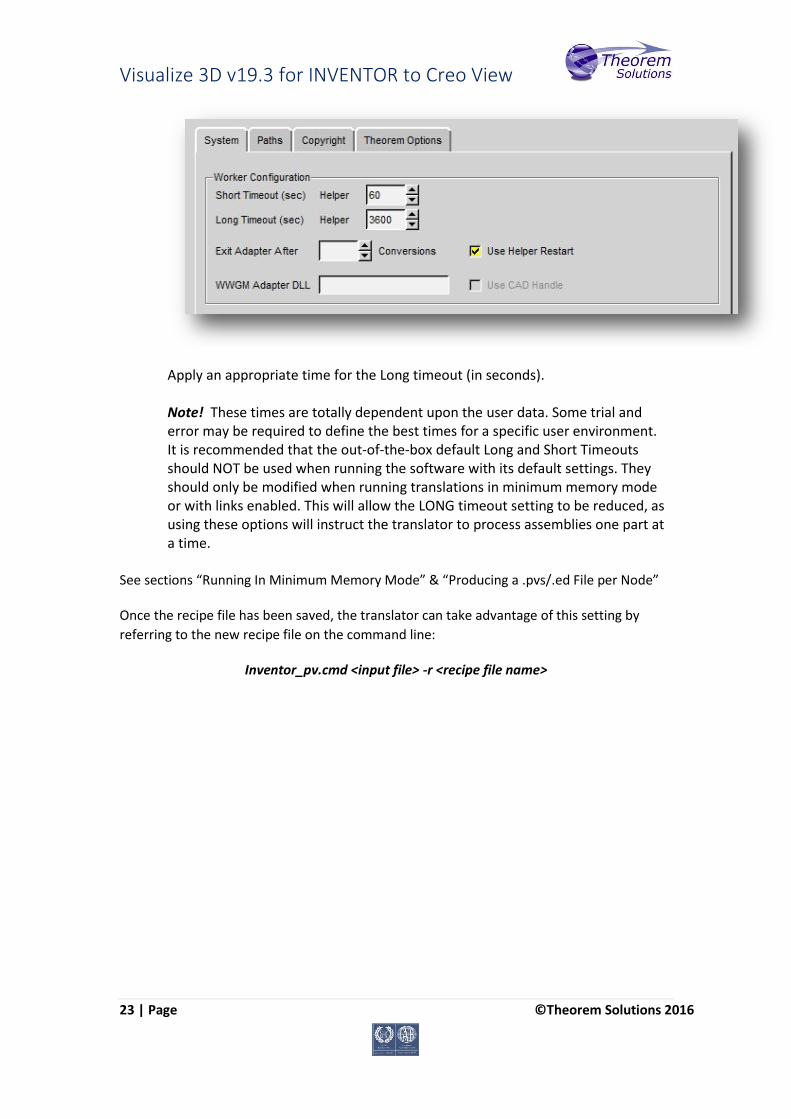
Process Timeouts Timeouts allow a user to control when an individual translation invoked from a Windchill environment should timeout. The Windchill interface allows 2 distinct timeout types to be defined, Long and Short. Two Long timeouts have been allocated to the INVENTOR->Creo View translator:
Long Timeout – Inventor_Read, to read each file from INVENTOR. Long Timeout – CreoView_Write, to write each file into Creo View
The Long Timeout value can be set as follows: 1. Launch the recipe editor: rcpedit.exe <recipe file name> 2. Select the Advanced Tab 3. Select the System Tab, the recipe editor GUI will be displayed as follows:
Visualize 3D v19.3 for INVENTOR to Creo View
23 | Page ©Theorem Solutions 2016
Apply an appropriate time for the Long timeout (in seconds). Note! These times are totally dependent upon the user data. Some trial and error may be required to define the best times for a specific user environment. It is recommended that the out-of-the-box default Long and Short Timeouts should NOT be used when running the software with its default settings. They should only be modified when running translations in minimum memory mode or with links enabled. This will allow the LONG timeout setting to be reduced, as using these options will instruct the translator to process assemblies one part at a time.
See sections “Running In Minimum Memory Mode” & “Producing a .pvs/.ed File per Node”
Once the recipe file has been saved, the translator can take advantage of this setting by
referring to the new recipe file on the command line:
Inventor_pv.cmd <input file> -r <recipe file name>

Visualize 3D v19.3 for INVENTOR to Creo View
24 | Page ©Theorem Solutions 2016
Appendix A – Theorem Configuration File
Introduction There are a number of optional pieces of information that can be provided to the Adapter
prior to execution. These will control the information that is finally written into the output
Creo View file by selecting specific data to be read from the input files processed.
These options are controlled by settings defined within the Theorem INVENTOR_Creo View
Adapter configuration file. To invoke these controls it is necessary to create the
configuration file and also identify the configuration filename and location.
Configuration File Format The configuration file is a simple ASCII text file generated with any available text editor. The
format of the file is such that each configuration command statement is specified on a
separate line. Blank characters separate any optional arguments related to the
configuration command statement.
e.g.
progress_file c:\TEMP\inv_pv.log
ignore_migration
Configuration File Location The location of the configuration file can be defined in one of 2 ways. The recommended
method is to use the recipe editor. See Setting the Additional Options File Name above.
Alternatively, the ‘TS_CFILE’ environment variable can be set to point to the INVENTOR Creo
View configuration file prior to starting the translation Adapter:
Syntax: set TS_CFILE=<configuration_filename>
e.g. set TS_CFILE=C:\theorem\data\inventor\configuration.txt

Visualize 3D v19.3 for INVENTOR to Creo View
25 | Page ©Theorem Solutions 2016
Appendix B – Theorem Support Advanced Options
Introduction The following environment variables are available to modify the Adapter’s behaviour under the guidance of the Theorem support team. It is recommended, under guidance from Theorem Support that these variables be set in the ts_env.bat file, if required. Where no value is suggested, set the variable with a value of 1: e.g.
set TSC_DEBUG_TIME=1
Diagnostics Variable Value Description
TSC_DEBUG_TIME 1 Annotates logs and screen output with time stamps.
The Diagnostic Logs -> Info recipe setting must be on
TSC_DEBUG 1 or 2 Annotate logs and screen output with debug data Note! Much of the TSC_DEBUG info is now re-directed via the –vm <level> command line option into the worker log
TSC_EXT_REF 1 Output specific debug for external references
TSC_LEAVE_GCO 1 Retain any intermediate GCO files
Filtering Variable Value Description
TS_OMIT_ATTRIBUTES 1 List of attribute names to be omitted
TS_DISABLE_OMIT_ATTRIBUTES 1 Allow all attributes through
Options Variable Value Description
TSC_EXT_REF_ASSY 1 Include Assemblies as an external reference set
TSC_DISABLE_LARGE_ASSY_PARTS 1 For large assembly processing, omit geometry processing
TSC_CFILE 1 Import general command line options via a file input
Visualize 3D v19.3 for INVENTOR to Creo View
26 | Page ©Theorem Solutions 2016
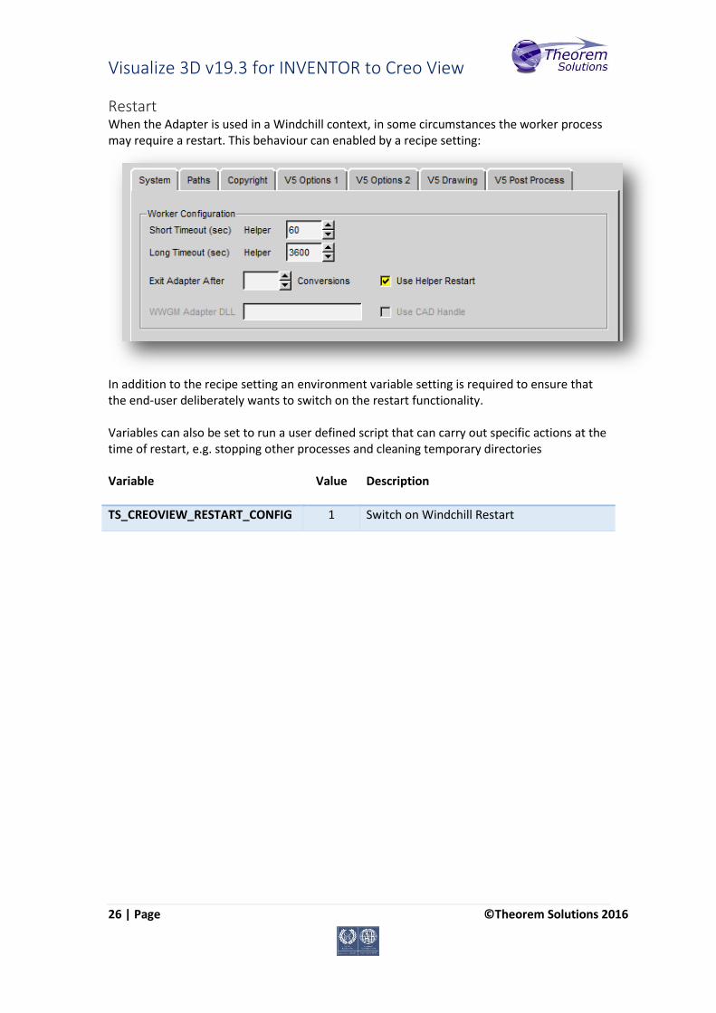
Restart When the Adapter is used in a Windchill context, in some circumstances the worker process may require a restart. This behaviour can enabled by a recipe setting:
In addition to the recipe setting an environment variable setting is required to ensure that the end-user deliberately wants to switch on the restart functionality. Variables can also be set to run a user defined script that can carry out specific actions at the time of restart, e.g. stopping other processes and cleaning temporary directories Variable Value Description
TS_CREOVIEW_RESTART_CONFIG 1 Switch on Windchill Restart
Visualize 3D v19.3 for INVENTOR to Creo View
27 | Page ©Theorem Solutions 2016
Screen Output By default error messages are reported to a temporary log file:
%TSC_TEMP_DIR%\ts_inv_pv_stderr.log
Error messages can be redirected by setting the variable below: Variable Value Description
TS_OUTPUT_STDERR 1 Redirects error messages to the screen log, or a log specified via the –vL command line argument
Worker Logs If –vm <level> worker logs are enabled and not re-directed to a log file, then these messages will default to stderr and be written to the ts_v5_pc_stderr.log
PVZ Output PVZ Output can be enabled by setting the recipe editor setting:
adapter/outputPvz=1
Issues Creating a INVENTOR Worker In the unlikely scenario that the recipe editor displays the create inventorworker button greyed out then it is necessary to run the %TS_INST%\bin\pview.reg file. This updates the registry and will enable this button.
Tessellation Settings In the unlikely event that a user should want to alter the tessellation settings in the Creo View output, the following settings can be manually added and modified in the recipe file under guidance from your PTC representative:
adapter/lod=Standard adapter/chordHeight=0.1
The above would result in a higher level of tessellation, and so a larger file.
adapter/lod=Standard adapter/chordHeight=10.0
The above would result in a lower level of tessellation, and so a smaller file.

Visualize 3D v19.3 for INVENTOR to Creo View
28 | Page ©Theorem Solutions 2016
Appendix C – Troubleshooting
Introduction Occasionally users may find translations are not successful, this can caused by many
different reasons, and the Adapter is highly configurable to deal with many of these
issues. This Appendix details how you can troubleshoot any problems that you may
experience with the INVENTOR Creo View Adapter.
The flow diagrams included in this section aim to guide the user as to which options are
likely to resolve more common issues.
Check List The following check list should be followed as a precursor to following the
troubleshooting flow charts:
Is the INVENTOR source data version supported by the Adapter?
(i.e. INVENTOR Release 2016 data cannot be translated with INVENTOR Release
2013 Adapter)
Is the machine performing the translation capable of loading the part/assembly into
INVENTOR?
This usually applies to very large assemblies, if the machine cannot load the
INVENTOR data, then the translation is not likely to be successful,
Does the user have the correct permissions to read/write all of the data, including any
log files?
Visualize 3D v19.3 for INVENTOR to Creo View
29 | Page ©Theorem Solutions 2016
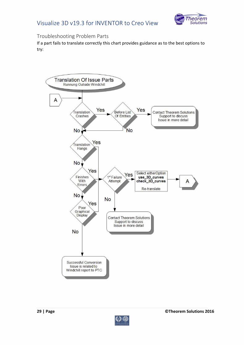
Troubleshooting Problem Parts If a part fails to translate correctly this chart provides guidance as to the best options to
try:
Visualize 3D v19.3 for INVENTOR to Creo View
30 | Page ©Theorem Solutions 2016
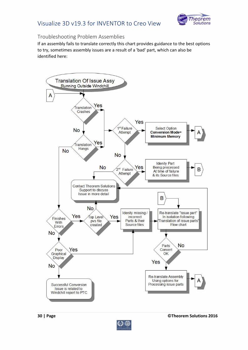
Troubleshooting Problem Assemblies If an assembly fails to translate correctly this chart provides guidance to the best options
to try, sometimes assembly issues are a result of a 'bad' part, which can also be
identified here:
Related Documents