User Guide SI-CANopen V2 Part Number: 0478-0101-03 Issue: 3

Welcome message from author
This document is posted to help you gain knowledge. Please leave a comment to let me know what you think about it! Share it to your friends and learn new things together.
Transcript
User Guide
SI-CANopen V2
Part Number: 0478-0101-03Issue: 3
Compliance Information
Manufacturer: Nidec Control Techniques Limited ("we", "our") Registered office: The Gro, Newtown, Powys, SY16 3BE United Kingdom Registered in: England and Wales, company registration number 01236886Manufacturer's EU Authorised Representative: Nidec Netherlands B.V., Kubus 155, 3364 DG Sliedrecht, the Netherlands, registered at the Dutch Trade Register under number 33213151; Tel. +31 (0)184 420 555, [email protected] instructionsWith reference to the UK Supply of Machinery (Safety) Regulations 2008 and the EU Machinery Directive 2006/42/EC, the English version of this Manual constitutes the original instructions. Manuals published in other languages are translations of the original instructions and the English language version of this Manual prevails over any other language version in the event of inconsistency. Documentation and user software toolsManuals, datasheets and software that we make available to users of our products can be downloaded from: http://www.drive-setup.com.
Warranty and liabilityThe contents of this Manual are presented for information purposes only, and while every effort has been made to ensure their accuracy, they are not to be construed as warranties or guarantees, express or implied, regarding the products or services described herein or their use or applicability. All sales are governed by our terms and conditions, which are available on request. We reserve the right to modify or improve the designs, specifications or performance of our products at any time without notice. For full details of the warranty terms applicable to the product, contact the supplier of the product.In no event and under no circumstances shall we be liable for damages and failures due to misuse, abuse, improper installation, or abnormal conditions of temperature, dust, or corrosion, or failures due to operation outside the published ratings for the product, nor shall we be liable for consequential and incidental damages of any kind. Environmental managementWe operate an Environmental Management System which complies with the requirements of ISO 14001:2015. Further information on our Environmental Statement can be found at: http://www.drive-setup.com/environment. Restriction and control of hazardous substancesThe products covered by this Manual comply with the following legislation and regulations on the restriction and control of hazardous substances:UK Restriction of the Use of Certain Hazardous Substances in Electrical and Electronic Equipment Regulations 2012UK REACH etc. (Amendment etc.) (EU Exit) Regulations 2020, European Union REACH Regulation EC 1907/2006EU restriction of the Use of certain Hazardous Substances in Electrical and Electronic Equipment (RoHS) - Directive 2011/65/EUEC Regulation 1907/2006 on the Registration, Evaluation, authorisation, and restriction of Chemicals (REACH)Chinese Administrative Measures for Restriction of Hazardous Substances in Electrical and Electronic Products 2016/07/01U.S. Environmental Protection Agency ("EPA") regulations under the Toxic Substances Control Act ("TSCA") MEPC 68/21 / Add.1, Annex 17, Resolution MEPC.269(68) 2015 Guidelines for the development of the inventory of hazardous materialsThe products covered by this Manual do not contain asbestos.Further information on REACH and RoHS can be found at: http://www.drive-setup.com/environment. Conflict mineralsWith reference to the Conflict Minerals (Compliance) (Northern Ireland) (EU Exit) Regulations 2020, the U.S. Dodd-Frank Wall Street Reform and Consumer Protection Act and Regulation (EU) 2017/821 of the European Parliament and of the European Council:We have implemented due diligence measures for responsible sourcing, we conduct conflict minerals surveys of relevant suppliers, we continually review due diligence information received from suppliers against company expectations and our review process includes corrective action management. We are not required to file an annual conflict minerals disclosure. Nidec Control Techniques Limited is not an issuer as defined by the U.S. SEC.
Disposal and recycling (WEEE)
Copyright and trade marksCopyright © 2 August 2021 Nidec Control Techniques Limited. All rights reserved. No part of this Manual may be reproduced or transmitted in any form or by any means including by photocopying, recording or by an information storage or retrieval system, without our permission in writing. The Nidec logo is a trade mark of Nidec Corporation. The Control Techniques logo is a trade mark owned by Nidec Control Techniques Limited. All other marks are property of their respective owners.
The products covered by this Manual fall within the scope of the UK Waste Electrical and Electronic Equipment Regulations 2013, EU Directive 2012/19/EU amended by EU Directive 2018/849 (EU) on Waste Electrical and Electronic Equipment (WEEE).
When electronic products reach the end of their useful life, they must not be disposed of along with domestic waste but should be recycled by a specialist recycler of electronic equipment. Our products are designed to be easily dismantled into their major component parts for efficient recycling. Most materials used in our products are suitable for recycling.
Our product packaging is of good quality and can be re-used. Smaller products are packaged in strong cardboard cartons which have a high recycled fibre content. Cartons can be re-used and recycled. Polythene, used in protective film and bags for the ground screws, can be recycled. When preparing to recycle or dispose of any product or packaging, please observe local legislation and best practice.

Contents
1 Safety information .................................51.1 Warnings, Cautions and Notes .............................51.2 Important safety information. Hazards.
Competence of designers and installers ...............51.3 Responsibility ........................................................51.4 Compliance with regulations .................................51.5 Electrical hazards ..................................................51.6 Stored electrical charge ........................................51.7 Mechanical hazards ..............................................51.8 Access to equipment .............................................51.9 Environmental limits ..............................................51.10 Hazardous environments ......................................61.11 Motor .....................................................................61.12 Mechanical brake control ......................................61.13 Adjusting parameters ............................................61.14 Electromagnetic compatibility (EMC) ....................6
2 Introduction ...........................................72.1 What Is CANopen? ...............................................72.2 What is SI-CANopen V2? .....................................92.3 List of supported drives .........................................92.4 General specification ............................................92.5 Option module identification ..................................92.6 Conventions used in this guide ..........................102.7 Conventions used for SI-CANopen V2 ...............102.8 Derivative Awareness .........................................102.9 Network Synchronisation ....................................10
3 Mechanical installation .......................113.1 General installation .............................................11
4 Electrical ..............................................124.1 SI-CANopen V2 terminal descriptions ................124.2 CANopen cable ...................................................124.3 CANopen network termination ............................124.4 SI-CANopen V2 cable shield connections ..........124.5 SI-CANopen V2 ground point .............................134.6 Maximum network length ....................................134.7 Spurs ...................................................................134.8 Minimum node to node cable length ...................13
5 Getting Started ....................................145.1 Parameter save and restore ...............................145.2 Module reset .......................................................145.3 Restoring module parameter default values .......145.4 Single Line Parameter Descriptions ....................145.5 PDO number configuration .................................225.6 PDO structure (PDOs A, B, C & D) .....................225.7 Types of set-up ...................................................225.8 Configuration setup overview ..............................245.9 Setup flowcharts .................................................25
6 Parameters ...........................................356.1 Menus .................................................................356.2 Menu 0 - Module Set-up .....................................366.3 Menu 1 - CANopen Setup ...................................476.4 Menu 2 - PDOA Setup ........................................556.5 Menu 3 - PDOB Setup ........................................596.6 Menu 4 - PDOC Setup ........................................626.7 Menu 5 - PDOD Setup ........................................656.8 Menu 6 - RPDO Fault .........................................686.9 Menu 7 - CAN Master Functions .........................696.10 Menu 9 - Resources ............................................71
7 Cyclic Data ...........................................727.1 What is a “Process Data Object”? .......................727.2 PDO data mapping errors ...................................727.3 Unused PDO data channels ...............................727.4 Changing PDO mapping parameters (via
controller/PLC) ....................................................727.5 Blank mapping parameters (via controller/PLC) .72
8 Non Cyclic Data ...................................748.1 Service data object (SDO) parameter access .....74
9 Control / status word ...........................769.1 What are control and status words? ...................769.2 Control word ........................................................769.3 Status word .........................................................77
10 EDS Files ..............................................7910.1 What are EDS files? ............................................7910.2 Generic EDS files ................................................7910.3 EDS File names ..................................................7910.4 Selecting the correct EDS Files ..........................79
SI-CANopen V2 User Guide 3

11 CANopen reference .............................8111.1 CANopen object dictionary ..................................8111.2 Basic data types ..................................................8511.3 0x1000 - Device type ..........................................8511.4 0x1001 - Error register ........................................8611.5 0x1002 - Manufacturer status register ................8611.6 0x1003 - Pre-defined error field ..........................8611.7 0x1005 - COB-ID SYNC ......................................8711.8 0x1006 - Communication cycle period ................8711.9 0x1007 - Synchronous window length ................8711.10 0x1008 - Manufacturer device name ...................8711.11 0x1009 - Manufacturer hardware version ...........8711.12 0x100A - Manufacturer software version ............8711.13 0x1010 - Store parameters .................................8811.14 0x1011 - Restore default parameters ..................8811.15 0x1014 - COB-ID EMCY .....................................8911.16 0x1016 - Consumer heartbeat time .....................8911.17 0x1017 - Producer heartbeat time .......................9011.18 0x1018 - Identity object .......................................9011.19 Flexible PDO numbering (0x2800 and 0x2801) ..9211.20 PDO mapping parameters ..................................9311.21 RxPDO communication parameters ....................9511.22 RxPDO mapping parameters ..............................9811.23 TxPDO communication parameters ....................9911.24 TxPDO profile specific mode .............................10111.25 TxPDO mapping parameters ............................10111.26 RxPDO, SYNC and missed heartbeat event
handling ............................................................10211.27 RxPDO event triggers .......................................10911.28 TxPDO event triggers ........................................11111.29 Inter-option DPLCAN Interface .........................11311.30 0x2862 - Background Associations ...................11511.31 0x3000 - Position Feedback Encoder Source ...11611.32 0x3003 - Homing Source ..................................11611.33 0x3004 - Additional Position Loop Scaling ........11711.34 0x3008 – Velocity Mode Redirection Enable ....11711.35 0x3009 - Manufacturer enhanced scaling ........11711.36 Network management objects (NMT) ...............11811.37 NMT commands ................................................11911.38 Layer setting services (LSS) .............................11911.39 0x1014 - Emergency object ..............................12411.40 Emergency object state .....................................12711.41 Device profiles ...................................................128
12 Diagnostics ........................................16812.1 Overview ...........................................................168
13 Glossary of terms ..............................172
4 SI-CANopen V2 User Guide
Safety information Introduction Mechanical
installation Electrical Getting Started Parameters Cyclic Data Non Cyclic
DataControl /
status word EDS Files CANopen reference Diagnostics Glossary of
terms Index
1 Safety information1.1 Warnings, Cautions and Notes
A Note contains information which helps to ensure correct operation of the product.
1.2 Important safety information. Hazards. Competence of designers and installers
This guide applies to products which control electric motors either directly (drives) or indirectly (controllers, option modules and other auxiliary equipment and accessories). In all cases the hazards associated with powerful electrical drives are present, and all safety information relating to drives and associated equipment must be observed.Specific warnings are given at the relevant places in this guide.Drives and controllers are intended as components for professional incorporation into complete systems. If installed incorrectly they may present a safety hazard. The drive uses high voltages and currents, carries a high level of stored electrical energy, and is used to control equipment which can cause injury. Close attention is required to the electrical installation and the system design to avoid hazards either in normal operation or in the event of equipment malfunction. System design, installation, commissioning/start-up and maintenance must be carried out by personnel who have the necessary training and competence. They must read this safety information and this guide carefully.
1.3 ResponsibilityIt is the responsibility of the installer to ensure that the equipment is installed correctly with regard to all instructions given in this guide. They must give due consideration to the safety of the complete system, so as to avoid the risk of injury both in normal operation and in the event of a fault or of reasonably foreseeable misuse.The manufacturer accepts no liability for any consequences resulting from inappropriate, negligent or incorrect installation of the equipment.
1.4 Compliance with regulationsThe installer is responsible for complying with all relevant regulations, such as national wiring regulations, accident prevention regulations and electromagnetic compatibility (EMC) regulations. Particular attention must be given to the cross-sectional areas of conductors, the selection of fuses or other protection, and protective ground (earth) connections.This guide contains instructions for achieving compliance with specific EMC standards.All machinery to be supplied within the European Union in which this product is used must comply with the following directives:2006/42/EC Safety of machinery.2014/30/EU: Electromagnetic Compatibility.
1.5 Electrical hazardsThe voltages used in the drive can cause severe electrical shock and/or burns, and could be lethal. Extreme care is necessary at all times when working with or adjacent to the drive. Hazardous voltage may be present in any of the following locations:• AC and DC supply cables and connections• Output cables and connections• Many internal parts of the drive, and external option unitsUnless otherwise indicated, control terminals are single insulated and must not be touched. The supply must be disconnected by an approved electrical isolation device before gaining access to the electrical connections.The STOP and Safe Torque Off functions of the drive do not isolate dangerous voltages from the output of the drive or from any external option unit. The drive must be installed in accordance with the instructions given in this guide. Failure to observe the instructions could result in a fire hazard.
1.6 Stored electrical chargeThe drive contains capacitors that remain charged to a potentially lethal voltage after the AC supply has been disconnected. If the drive has been energized, the AC supply must be isolated at least ten minutes before work may continue.
1.7 Mechanical hazardsCareful consideration must be given to the functions of the drive or controller which might result in a hazard, either through their intended behaviour or through incorrect operation due to a fault. In any application where a malfunction of the drive or its control system could lead to or allow damage, loss or injury, a risk analysis must be carried out, and where necessary, further measures taken to reduce the risk - for example, an over-speed protection device in case of failure of the speed control, or a fail-safe mechanical brake in case of loss of motor braking.With the sole exception of the Safe Torque Off function, none of the drive functions must be used to ensure safety of personnel, i.e. they must not be used for safety-related functions.The Safe Torque Off function may be used in a safety-related application. The system designer is responsible for ensuring that the complete system is safe and designed correctly according to the relevant safety standards.The design of safety-related control systems must only be done by personnel with the required training and experience. The Safe Torque Off function will only ensure the safety of a machine if it is correctly incorporated into a complete safety system. The system must be subject to a risk assessment to confirm that the residual risk of an unsafe event is at an acceptable level for the application.
1.8 Access to equipmentAccess must be restricted to authorized personnel only. Safety regulations which apply at the place of use must be complied with.
1.9 Environmental limitsInstructions in this guide regarding transport, storage, installation and use of the equipment must be complied with, including the specified environmental limits. This includes temperature, humidity, contamination, shock and vibration. Drives must not be subjected to excessive physical force.
A Warning contains information which is essential for avoiding a safety hazard.
A Caution contains information which is necessary for avoiding a risk of damage to the product or other equipment.
WARNING
CAUTION
NOTE
SI-CANopen V2 User Guide 5
Safety information Introduction Mechanical
installation Electrical Getting Started Parameters Cyclic Data Non Cyclic
DataControl /
status word EDS Files CANopen reference Diagnostics Glossary of
terms Index
1.10 Hazardous environmentsThe equipment must not be installed in a hazardous environment (i.e. a potentially explosive environment).
1.11 MotorThe safety of the motor under variable speed conditions must be ensured.To avoid the risk of physical injury, do not exceed the maximum specified speed of the motor.Low speeds may cause the motor to overheat because the cooling fan becomes less effective, causing a fire hazard. The motor should be installed with a protection thermistor. If necessary, an electric forced vent fan should be used.The values of the motor parameters set in the drive affect the protection of the motor. The default values in the drive must not be relied upon. It is essential that the correct value is entered in the Motor Rated Current parameter.
1.12 Mechanical brake controlAny brake control functions are provided to allow well co-ordinated operation of an external brake with the drive. While both hardware and software are designed to high standards of quality and robustness, they are not intended for use as safety functions, i.e. where a fault or failure would result in a risk of injury. In any application where the incorrect operation of the brake release mechanism could result in injury, independent protection devices of proven integrity must also be incorporated.
1.13 Adjusting parametersSome parameters have a profound effect on the operation of the drive. They must not be altered without careful consideration of the impact on the controlled system. Measures must be taken to prevent unwanted changes due to error or tampering.
1.14 Electromagnetic compatibility (EMC)Installation instructions for a range of EMC environments are provided in the relevant Power Installation Guide. If the installation is poorly designed or other equipment does not comply with suitable standards for EMC, the product might cause or suffer from disturbance due to electromagnetic interaction with other equipment. It is the responsibility of the installer to ensure that the equipment or system into which the product is incorporated complies with the relevant EMC legislation in the place of use.
6 SI-CANopen V2 User Guide

Safety information Introduction Mechanical
installation Electrical Getting Started Parameters Cyclic Data Non Cyclic
DataControl /
status word EDS Files CANopen reference Diagnostics Glossary of
terms Index
2 Introduction2.1 What Is CANopen?CANopen is a networking system that falls into the generic category of Fieldbus. Fieldbuses are generally defined as industrial networking systems that are intended to replace traditional wiring systems. Figure 2-1 shows the traditional cabling requirements to transfer signals between a controller and two nodes.
Figure 2-1 Traditional cable layout
Table 2-1 details how the wiring is used to communicate data between the controller and the nodes. Each signal which is communicated requires one signal wire giving a total of 66 signal wires plus a 0 V return.
Table 2-1 Traditional wiring details
A fieldbus topology such as CANopen allows the same configuration to be realized using only two signal wires plus a shield. This method of communication saves significantly on the amount of cabling required and can improve overall system reliability as the number of interconnections is greatly reduced.
Hardwired controller
1 2
Dig
ital1
AD
igita
l1B
Digital2A
Digital2B
Digital 1A Digital 1B Digital 2A Digital 2B
Analog 1 Analog 2
Analog 1 Analog 2
Number of signals Type Source / Destination Description16 digital Inputs node 1 to controller status signals16 digital outputs controller to node 1 control signals1 analog output controller to node 1 control signal
16 digital inputs node 2 to controller status signals16 digital outputs controller to node 2 control signals1 analog output controller to node 2 control signal
SI-CANopen V2 User Guide 7
Safety information Introduction Mechanical
installation Electrical Getting Started Parameters Cyclic Data Non Cyclic
DataControl /
status word EDS Files CANopen reference Diagnostics Glossary of
terms Index
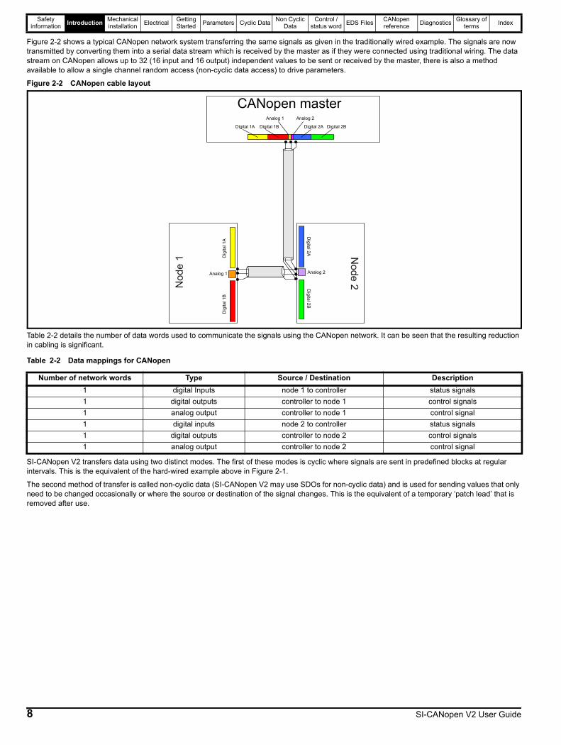
Figure 2-2 shows a typical CANopen network system transferring the same signals as given in the traditionally wired example. The signals are now transmitted by converting them into a serial data stream which is received by the master as if they were connected using traditional wiring. The data stream on CANopen allows up to 32 (16 input and 16 output) independent values to be sent or received by the master, there is also a method available to allow a single channel random access (non-cyclic data access) to drive parameters.
Figure 2-2 CANopen cable layout
Table 2-2 details the number of data words used to communicate the signals using the CANopen network. It can be seen that the resulting reduction in cabling is significant.
Table 2-2 Data mappings for CANopen
SI-CANopen V2 transfers data using two distinct modes. The first of these modes is cyclic where signals are sent in predefined blocks at regular intervals. This is the equivalent of the hard-wired example above in Figure 2-1.
The second method of transfer is called non-cyclic data (SI-CANopen V2 may use SDOs for non-cyclic data) and is used for sending values that only need to be changed occasionally or where the source or destination of the signal changes. This is the equivalent of a temporary ‘patch lead’ that is removed after use.
CANopen masterDigital 1A Digital 1B Digital 2A Digital 2B
Analog 1
Digital2A
Digital2B
Dig
ital1
AD
igita
l1B
Nod
e1 N
ode2
Analog 2
Analog 1 Analog 2
Number of network words Type Source / Destination Description1 digital Inputs node 1 to controller status signals1 digital outputs controller to node 1 control signals1 analog output controller to node 1 control signal 1 digital inputs node 2 to controller status signals1 digital outputs controller to node 2 control signals1 analog output controller to node 2 control signal
8 SI-CANopen V2 User Guide
Safety information Introduction Mechanical
installation Electrical Getting Started Parameters Cyclic Data Non Cyclic
DataControl /
status word EDS Files CANopen reference Diagnostics Glossary of
terms Index
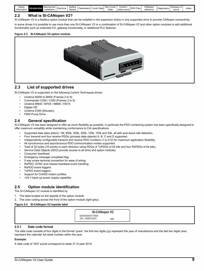
2.2 What is SI-CANopen V2?SI-CANopen V2 is a fieldbus option module that can be installed in the expansion slot(s) in any supported drive to provide CANopen connectivity.
In some drives it is possible to use more than one SI-CANopen V2 or a combination of SI-CANopen V2 and other option modules to add additional functionality such as extended I/O, gateway functionality, or additional PLC features.
Figure 2-3 SI-CANopen V2 option module
2.3 List of supported drives SI-CANopen V2 is supported on the following Control Techniques drives:
• Unidrive M200 to M400 (Frames 2 to 9)• Commander C200 / C300 (Frames 2 to 9)• Unidrive M600 / M70X / M88X / HS7X• Digitax HD• Unidrive E300 (Elevator)• F600 Pump Drive
2.4 General specificationSI-CANopen V2 has been designed to offer as much flexibility as possible, in particular the PDO numbering system has been specifically designed to offer maximum versatility while maintaining conformance to CiA specifications.
• Supported data rates (bits/s): 1M, 800k, 500k, 250k, 125k, 100k and 50k, all with auto-baud rate detection.• Four transmit and four receive PDOs (process data objects) A, B, C and D supported.• Independently configurable transmit and receive PDO numbers (1 to 512) for maximum application flexibility.• All synchronous and asynchronous PDO communication modes supported.• Total of 32 bytes (16 words) in each direction using PDOs (4 TxPDOs of 64 bits and four RxPDOs of 64 bits).• Service Data Objects (SDO) provide access to all drive and option modules.• Consumer heartbeat.• Emergency message completed flag.• 5 way screw terminal connection for ease of wiring.• RxPDO, SYNC and missed heartbeat event handling.• RxPDO event triggers.• TxPDO event triggers.• Support for CiA402 motion profiles.• +24 V back-up power supply capability.
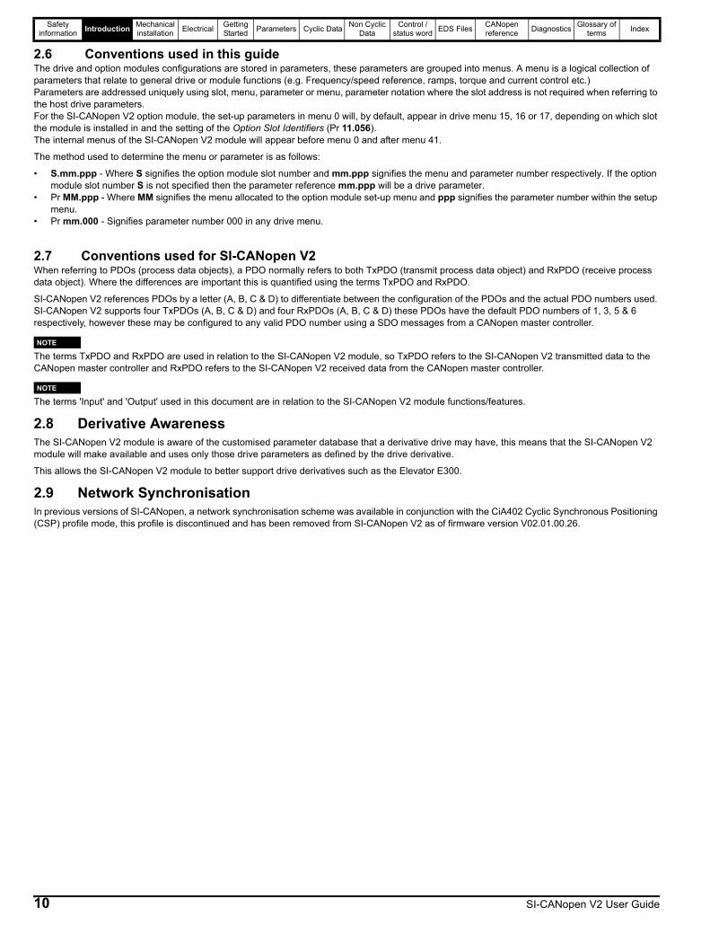
2.5 Option module identification The SI-CANopen V2 module is identified by:
1. The label located on the topside of the option module.2. The color coding across the front of the option module (light grey).
Figure 2-4 SI-CANopen V2 topside label
2.5.1 Date code formatThe date code consists of four digits in the format 'yyww', the first two digits (yy) represent the year of manufacture and the last two digits (ww) represent the calendar full week number within the year.
Example:A date code of 1937 would correspond to week 37 of year 2019.
SI-CANopen V2
1937S/N : 895851200382400000017600
SI-CANopen V2 User Guide 9
Safety information Introduction Mechanical
installation Electrical Getting Started Parameters Cyclic Data Non Cyclic
DataControl /
status word EDS Files CANopen reference Diagnostics Glossary of
terms Index
2.6 Conventions used in this guideThe drive and option modules configurations are stored in parameters, these parameters are grouped into menus. A menu is a logical collection of parameters that relate to general drive or module functions (e.g. Frequency/speed reference, ramps, torque and current control etc.)Parameters are addressed uniquely using slot, menu, parameter or menu, parameter notation where the slot address is not required when referring to the host drive parameters.For the SI-CANopen V2 option module, the set-up parameters in menu 0 will, by default, appear in drive menu 15, 16 or 17, depending on which slot the module is installed in and the setting of the Option Slot Identifiers (Pr 11.056).The internal menus of the SI-CANopen V2 module will appear before menu 0 and after menu 41.
The method used to determine the menu or parameter is as follows:
• S.mm.ppp - Where S signifies the option module slot number and mm.ppp signifies the menu and parameter number respectively. If the option module slot number S is not specified then the parameter reference mm.ppp will be a drive parameter.
• Pr MM.ppp - Where MM signifies the menu allocated to the option module set-up menu and ppp signifies the parameter number within the setup menu.
• Pr mm.000 - Signifies parameter number 000 in any drive menu.
2.7 Conventions used for SI-CANopen V2When referring to PDOs (process data objects), a PDO normally refers to both TxPDO (transmit process data object) and RxPDO (receive process data object). Where the differences are important this is quantified using the terms TxPDO and RxPDO.
SI-CANopen V2 references PDOs by a letter (A, B, C & D) to differentiate between the configuration of the PDOs and the actual PDO numbers used. SI-CANopen V2 supports four TxPDOs (A, B, C & D) and four RxPDOs (A, B, C & D) these PDOs have the default PDO numbers of 1, 3, 5 & 6 respectively, however these may be configured to any valid PDO number using a SDO messages from a CANopen master controller.
The terms TxPDO and RxPDO are used in relation to the SI-CANopen V2 module, so TxPDO refers to the SI-CANopen V2 transmitted data to the CANopen master controller and RxPDO refers to the SI-CANopen V2 received data from the CANopen master controller.
The terms 'Input' and 'Output' used in this document are in relation to the SI-CANopen V2 module functions/features.
2.8 Derivative AwarenessThe SI-CANopen V2 module is aware of the customised parameter database that a derivative drive may have, this means that the SI-CANopen V2 module will make available and uses only those drive parameters as defined by the drive derivative.
This allows the SI-CANopen V2 module to better support drive derivatives such as the Elevator E300.
2.9 Network SynchronisationIn previous versions of SI-CANopen, a network synchronisation scheme was available in conjunction with the CiA402 Cyclic Synchronous Positioning (CSP) profile mode, this profile is discontinued and has been removed from SI-CANopen V2 as of firmware version V02.01.00.26.
NOTE
NOTE
10 SI-CANopen V2 User Guide

Safety information Introduction Mechanical
installation Electrical Getting Started Parameters Cyclic Data Non Cyclic
DataControl /
status word EDS Files CANopen reference Diagnostics Glossary of
terms Index
SI-CANopen V2 User Guide 11
3 Mechanical installation
3.1 General installationFor information on the installation of the SI-CANopen V2 option module please refer to the installation sheet provided with the option module.
Option modules can only be installed on drives that have the option module slot functionality.
Before installing or removing an option module from any drive, ensure the AC supply has been disconnected for at least 10 minutes and refer to section 1 Safety information on page 5. If using a DC bus supply ensure this is fully discharged before working on any drive or option module.
WARNING
NOTE

Safety information Introduction Mechanical
installation Electrical Getting Started Parameters Cyclic Data Non Cyclic
DataControl /
status word EDS Files CANopen reference Diagnostics Glossary of
terms Index
4 Electrical4.1 SI-CANopen V2 terminal descriptionsSI-CANopen V2 has a standard 5-way screw terminal block connector for the CANopen network connection as shown in Figure 4-1. Figure 4-1 SI-CANopen V2 - connector view
Table 4-1 SI-CANopen V2 terminal descriptions
An external 24 V supply can be connected to terminals 1 and 5, this 24 V input allows the line driver circuitry to remain powered if the drive is powered down. This maintains the CANopen network load characteristics but does not allow the SI-CANopen V2 module to communicate with the CANopen master controller whilst the drive is powered down.
4.2 CANopen cableCANopen cable consists of 2 twisted pairs plus an overall braided shield with the colour coding as shown in Table 4-1. It is important that the colour coding is maintained to minimise the time required if any troubleshooting is required.The data wires are white and blue, and the network power supply wires are red and black.CANopen networks run at high data rates and require cable specifically designed to carry high frequency signals. Low quality cable will attenuate the signals and may render the signal unreadable for the other nodes on the network. Cable specifications and a list of approved manufacturers of cable for use on CANopen networks is available on the CAN in Automation (CiA) web site at www.can-cia.org.
4.3 CANopen network terminationIt is vital when dealing with high-speed communications networks, to ensure that the network communications cable is installed with the specified termination resistor network at each end of the cable segment. This prevents signals from being reflected back down the cable and causing interference.During installation of a CANopen network, 120 Ω 0.25 W termination resistors should be installed across the CAN-H and CAN-L lines at both ends of the network segment.
If too many termination resistors are installed on a CANopen network, the network will be over-loaded, resulting in reduced signal levels. This may cause nodes to miss some bits of information, resulting in potential transmission errors.
4.4 SI-CANopen V2 cable shield connectionsThe SI-CANopen V2 should be wired with the cable shields isolated from ground at each drive. The cable shields should be linked together at the point where they emerge from the cable, and formed into a short pigtail to be connected to terminal 3 on the SI-CANopen V2 terminal connector.
Terminal Number Cable Colour Function Description1 Black 0 V 0 V SI-CANopen external supply2 Blue CAN-L Negative data line3 Braided Shield Shield Cable braided shield connection4 White CAN-H Positive data line5 Red +24 V +24 V SI-CANopen external supply
Any external supply must be suitably installed to prevent noise on the network.
Control Techniques can only guarantee correct and reliable operation of SI-CANopen V2 if all other equipment installed on the CANopen network (including the network cable) has been approved by the CiA.
Failure to terminate a network correctly can seriously affect the operation of the network. If the correct termination resistors are not in-stalled, the noise immunity of the network is greatly reduced.
The CANopen cable can be tie-wrapped to the grounding bar or local convenient mounting that is not live to provide strain relief, but the CANopen cable shield must be kept isolated from ground at each node. The only exception to this is the CANopen ground point as de-scribed in section 4.5 below.
1 2 3 4 5
+24 V external power supply (red)
CAN-H positive data line (white)
Cable screen (braided shield)
CAN-L negative data line (blue)
0 V external power supply (black)
WARNING
NOTE
NOTE
NOTE
12 SI-CANopen V2 User Guide
Safety information Introduction Mechanical
installation Electrical Getting Started Parameters Cyclic Data Non Cyclic
DataControl /
status word EDS Files CANopen reference Diagnostics Glossary of
terms Index
4.5 SI-CANopen V2 ground pointThe CANopen cable shield must be grounded AT ONE POINT only, usually near the centre point of the cable run. This is to prevent the cable shield from becoming live in the event of catastrophic failure of another device on the CANopen network.
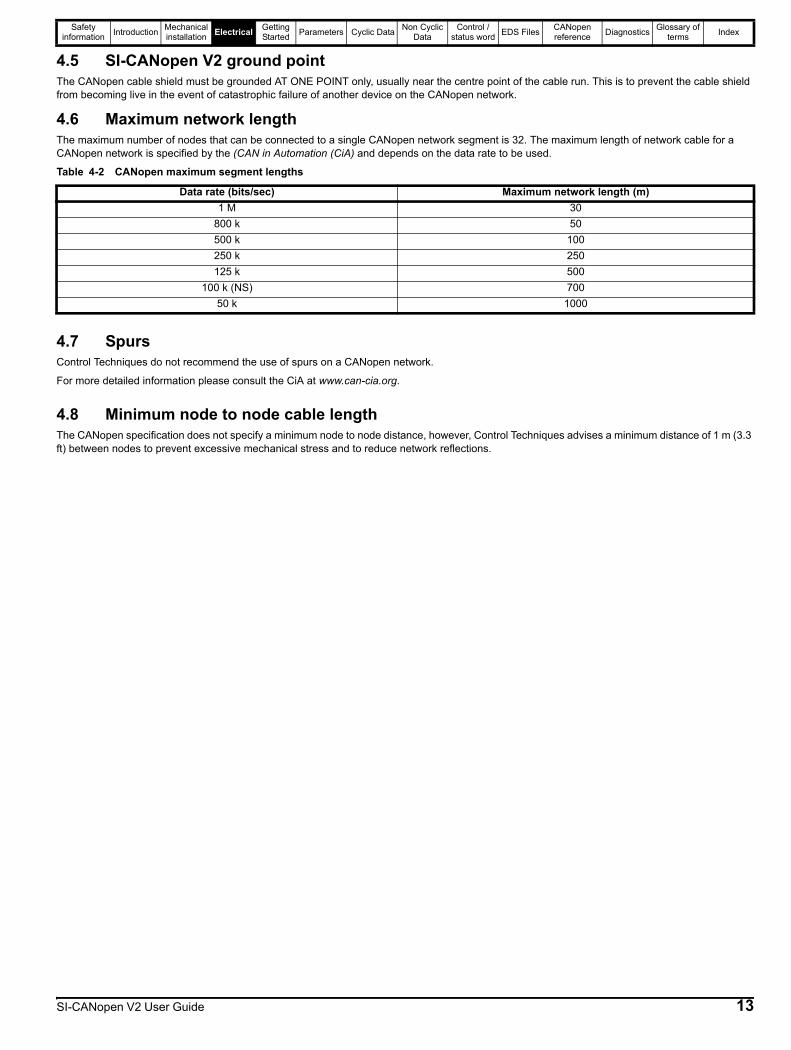
4.6 Maximum network lengthThe maximum number of nodes that can be connected to a single CANopen network segment is 32. The maximum length of network cable for a CANopen network is specified by the (CAN in Automation (CiA) and depends on the data rate to be used.
Table 4-2 CANopen maximum segment lengths
4.7 SpursControl Techniques do not recommend the use of spurs on a CANopen network.
For more detailed information please consult the CiA at www.can-cia.org.
4.8 Minimum node to node cable lengthThe CANopen specification does not specify a minimum node to node distance, however, Control Techniques advises a minimum distance of 1 m (3.3 ft) between nodes to prevent excessive mechanical stress and to reduce network reflections.
Data rate (bits/sec) Maximum network length (m)1 M 30
800 k 50500 k 100250 k 250125 k 500
100 k (NS) 70050 k 1000
SI-CANopen V2 User Guide 13
Safety information Introduction Mechanical
installation Electrical Getting Started Parameters Cyclic Data Non Cyclic
DataControl /
status word EDS Files CANopen reference Diagnostics Glossary of
terms Index
5 Getting StartedThis section is intended to provide a generic guide for setting up SI-CANopen V2 and a master controller/PLC. Figure 5-1 PDO Configuration setup overview on page 24 is intended as the starting point for a new installation. The following pages detail the various methods available to configure SI-CANopen V2. It is recommended that all of this section is read, before attempting to configure a system.
5.1 Parameter save and restoreParameters in the module are saved when a normal drive parameter save is initiated by selecting "Save Parameters" or setting a value of 1000 in Pr mm.000 and performing a drive reset. (If the drive is in the under voltage state or is supplied from a low voltage power supply then a value of 1001 must be set in Pr mm.000 and a drive reset performed).
Any user-saved parameters in the option module's internal menus are stored in non-volatile memory on the module and not in the drive. Therefore, if the module is moved to a different slot or to a different drive, then any saved parameter values will follow the module. If a module is to be replaced, ensure that the parameter values for the module have been backed up before replacing it.
5.2 Module resetA reset of the SI-CANopen V2 module can be performed by the methods detailed below.
• Set Pr S.00.007 (or Pr MM.007) to On (1). This will only reset the module fitted in slot S.• Select "Reset modules" or set a value of 1070 in Pr mm.000, and performing a drive reset. This will perform a reset of all option modules installed
in the drive.
5.3 Restoring module parameter default valuesSetting Pr S.00.008 (or Pr MM.008) to On (1) and performing a module reset by setting Pr S.00.007 (or Pr MM.007) to On (1) will return all parameters in the SI-CANopen V2 module to their default values.
Parameters in the SI-CANopen V2 module will also be set to their default values when drive parameters are returned to their default values.
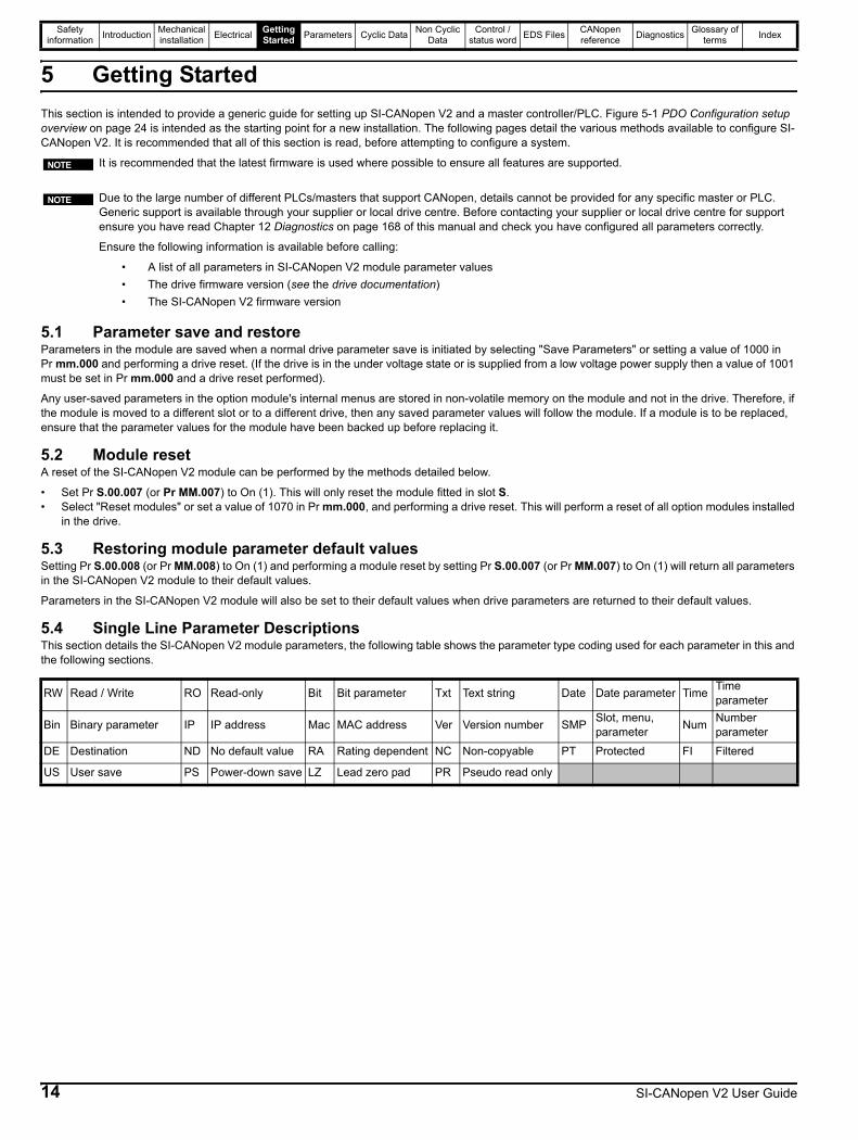
5.4 Single Line Parameter DescriptionsThis section details the SI-CANopen V2 module parameters, the following table shows the parameter type coding used for each parameter in this and the following sections.
It is recommended that the latest firmware is used where possible to ensure all features are supported.
Due to the large number of different PLCs/masters that support CANopen, details cannot be provided for any specific master or PLC. Generic support is available through your supplier or local drive centre. Before contacting your supplier or local drive centre for support ensure you have read Chapter 12 Diagnostics on page 168 of this manual and check you have configured all parameters correctly.
Ensure the following information is available before calling:
• A list of all parameters in SI-CANopen V2 module parameter values• The drive firmware version (see the drive documentation)• The SI-CANopen V2 firmware version
NOTE
NOTE
RW Read / Write RO Read-only Bit Bit parameter Txt Text string Date Date parameter Time Time parameter
Bin Binary parameter IP IP address Mac MAC address Ver Version number SMP Slot, menu, parameter Num Number
parameterDE Destination ND No default value RA Rating dependent NC Non-copyable PT Protected FI Filtered
US User save PS Power-down save LZ Lead zero pad PR Pseudo read only
14 SI-CANopen V2 User Guide

Safety information Introduction Mechanical
installation Electrical Getting Started Parameters Cyclic Data Non Cyclic
DataControl /
status word EDS Files CANopen reference Diagnostics Glossary of
terms Index
5.4.1 Menu 0 - SI-CANopen V2 Setup Information
5.4.2 Menu 1 - CANopen Interface Setup
Parameter Range Default Type
S.00.001 Module ID 0 to 65535 RO Num ND NC PT
S.00.002 Software Version00.00.00.00
to99.99.99.99
RO Ver ND NC PT
S.00.003 Hardware Version 0.00 to 99.99 RO Num ND NC PT
S.00.004 Serial Number LS 0 to 99999999 RO LZ ND NC PT
S.00.005 Serial Number MS 0 to 99999999 RO Num ND NC PT
S.00.006 Module StatusInitialising (0), OK (1), Config (2),
Error (3)RO Txt ND NC PT
S.00.007 Module Reset Off (0) or On (1) Off (0) RW Bit NC
S.00.008 Module Default Off (0) or On (1) Off (0) RW Bit NC
S.00.012 Drive stored Node Address enable
Off (0) or On (1) Off (0) RW Bit US
S.00.013 Drive stored Node Address
0 to 127 0 RW Num US
S.00.060 Parameter Channel Command
0 to 2 0 RW Txt NC
S.00.061 Parameter Channel Status
0 to 3 0 RO Txt NC PT
S.00.062 Parameter Channel Parameter Address
0 to 65535 0 RW Num NC
S.00.063 Parameter Channel Value LSW / Error
-32768 to 32767 0 RW Num NC
S.00.064 Parameter Channel Value MSW
-32768 to 32767 0 RW Num NC
Parameter Range () Default () Type
S.01.001 CANopen Interface Mode Off (0), On (1), On No Bootup (2) On (1) RW Txt US
S.01.002 Reset CANopen Interface Off (0) or On (1) Off (0) RW Bit
S.01.003 Default CANopen Interface Off (0) or On (1) Off (0) RW Bit
S.01.004 CANopen Node Address 0 to 127 0 RW Num US
S.01.005 Baud rate1Mbps (0), 800kbps (1), 500kbps (2), 250kbps (3),
125kbps (4), 50kbps (5), Auto detect (6), 100kbps (NS) (7)
500kbps (2) RW Txt NC PT US
S.01.006 CANopen Network Diagnostic
Network OK (0), Internal HW Fail (1), Init OK (2), No PDO Cfg (3), Config Error (4), Software Error (5),
Baud detecting (6), Device Disabled (7), Initialise Delay (8), Bus Off (9)
RO Txt ND NC PT
S.01.007 Cyclic Data Rate 0 to 9999 Messages/s RO Num ND NC PT
S.01.008 PDO Configuration Source By Menu (0), By Master (1) By Menu (0) RW Txt US
S.01.010 Timeout Delay 0 to 3000 ms 0 ms RW Num US
S.01.011 Timeout Action Trip (0), Send flt values (1), Clear output (2), Hold last (3), No action (4) Trip (0) RW Txt US
S.01.012 Timeout Event Destination This slot (0), Slot 1 (1), Slot 2 (2), Slot 3 (3), Slot 4 (4) This slot (0) RW Txt US
S.01.013 Timeout Event Type No event (0), Event 0 (1), Event1 (2), Event2 (3), Event3 (4), Event4 (5) No event (0) RW Txt US
S.01.014 PDO Data Alignment 32 bit (0), 16 bit (1), 8 bit (2) 32 bit (0) RW Txt US
S.01.020 CiA 402 profiles Enable Off (0) or On (1) Off (0) RW Bit US
SI-CANopen V2 User Guide 15

Safety information Introduction Mechanical
installation Electrical Getting Started Parameters Cyclic Data Non Cyclic
DataControl /
status word EDS Files CANopen reference Diagnostics Glossary of
terms Index
S.01.021 Compatibility ModeHybrid (0), UNIDRIVE SP (1), COMMANDER SK (2),
UNIDRIVE M (3), SK PDO COMPAT (4), SDO SIZE COMPAT (5), CIA402 Profile (6)
UNIDRIVE M (3) RW Txt US
S.01.022 Compatibility Mode Software Revision 00.00.00.00 to 99.99.99.99 00.00.00.00 RW Ver PT US
S.01.023 Compatibility Mode Serial Number 0 to 999999999 0 RW Num PT US
S.01.024 User Program Object Priority None (0), Internal (1), User Program (2) None (0) RW Txt PT US
S.01.030 CANopen Identification Override -2147483648 to 2147483647 0 RW Num PT US
Parameter Range () Default () Type
16 SI-CANopen V2 User Guide

Safety information Introduction Mechanical
installation Electrical Getting Started Parameters Cyclic Data Non Cyclic
DataControl /
status word EDS Files CANopen reference Diagnostics Glossary of
terms Index
5.4.3 Menu 2 - PDOA SetupParameter Range () Default () Type
S.02.001 TPDOA Length 0 to 4 4 RW Num NC
S.02.002 RPDOA Length 0 to 4 4 RW Num NC
S.02.003 TPDOA Transmission Type 0 to 255 255 RW Num US
S.02.004 TPDOA Mapping Status
Mapping OK (0), Too Many Map (1), No Mapping (2), Read Mismatch (3), Hole In Mapping (4),
Duplicate Map (5), Length Mismatch (6), Reserved (7), Trans Type (8)
Mapping OK (0) RO Txt NC PT
S.02.005 RPDOA Mapping Status
Mapping OK (0), Too Many Map (1), No Mapping (2), Read Mismatch (3), Hole In Mapping (4),
Duplicate Map (5), Length Mismatch (6), Reserved (7), Trans Type (8), Out of Memory (9)
Mapping OK (0) RO Txt NC PT
S.02.006 TPDOA Processing Time 0 to 65535 ms RO Num ND NC PT
S.02.007 RPDOA Processing Time 0 to 65535 ms RO Num ND NC PT
S.02.008 PDOA Input Consistency Enable Off (0) or On (1) Off (0) RW Bit US
S.02.009 PDOA Input Consistency Trigger Parameter 0.00.000 to 5.99.999 0.00.000 RW SMP US
S.02.010 PDOA Output Consistency Enable Off (0) or On (1) Off (0) RW Bit US
S.02.011 PDOA Output Consistency Trigger Parameter 0.00.000 to 5.99.999 0.00.000 RW SMP US
S.02.012 PDOA Event Trigger Off (0) or On (1) Off (0) RW Bit US
S.02.013 TPDOA Number 1 to 512 1 RW Num US
S.02.014 RPDOA Number 1 to 512 1 RW Num US
S.02.015 TPDOA Mapping Parameter 1 0.00.000 to 5.99.999 0.10.040 RW SMP US
S.02.016 TPDOA Mapping Parameter 2 0.00.000 to 5.99.999 0.02.001 RW SMP US
S.02.017 TPDOA Mapping Parameter 3 0.00.000 to 5.99.999 0.00.000 RW SMP US
S.02.018 TPDOA Mapping Parameter 4 0.00.000 to 5.99.999 0.00.000 RW SMP US
S.02.019 RPDOA Mapping Parameter 1 0.00.000 to 5.99.999 0.06.042 RW SMP US
S.02.020 RPDOA Mapping Parameter 2 0.00.000 to 5.99.999 0.01.021 RW SMP US
S.02.021 RPDOA Mapping Parameter 3 0.00.000 to 5.99.999 0.00.000 RW SMP US
S.02.022 RPDOA Mapping Parameter 4 0.00.000 to 5.99.999 0.00.000 RW SMP US
SI-CANopen V2 User Guide 17

Safety information Introduction Mechanical
installation Electrical Getting Started Parameters Cyclic Data Non Cyclic
DataControl /
status word EDS Files CANopen reference Diagnostics Glossary of
terms Index
5.4.4 Menu 3 - PDOB SetupParameter Range () Default () Type
S.03.001 TPDOB Length 0 to 4 4 RW Num NC
S.03.002 RPDOB Length 0 to 4 4 RW Num NC
S.03.003 TPDOB Transmission Type 0 to 255 255 RW Num US
S.03.004 TPDOB Mapping Status
Mapping OK (0), Too Many Map (1), No Mapping (2), Read Mismatch (3), Hole In Mapping (4), Duplicate Map (5),
Length Mismatch (6), Reserved (7), Trans Type (8), Out of Memory (9)
Mapping OK (0) RO Txt NC PT
S.03.005 RPDOB Mapping Status
Mapping OK (0), Too Many Map (1), No Mapping (2), Read Mismatch (3), Hole In Mapping (4), Duplicate Map (5),
Length Mismatch (6), Reserved (7), Trans Type (8), Out of Memory (9)
Mapping OK (0) RO Txt NC PT
S.03.006 TPDOB Processing Time 0 to 65535 ms RO Num ND NC PT
S.03.007 RPDOB Processing Time 0 to 65535 ms RO Num ND NC PT
S.03.008 PDOB Input Consistency Enable Off (0) or On (1) Off (0) RW Bit US
S.03.009 PDOB Input Consistency Trigger Parameter 0.00.000 to 5.99.999 0.00.000 RW SMP US
S.03.010 PDOB Output Consistency Enable Off (0) or On (1) Off (0) RW Bit US
S.03.011PDOB Output Consistency Trigger Parameter
0.00.000 to 5.99.999 0.00.000 RW SMP US
S.03.012 PDOB Event Trigger Off (0) or On (1) Off (0) RW Bit US
S.03.013 TPDOB Number 1 to 512 3 RW Num US
S.03.014 RPDOB Number 1 to 512 3 RW Num US
S.03.015 TPDOB Mapping Parameter 1 0.00.000 to 5.99.999 0.00.000 RW SMP US
S.03.016 TPDOB Mapping Parameter 2 0.00.000 to 5.99.999 0.00.000 RW SMP US
S.03.017 TPDOB Mapping Parameter 3 0.00.000 to 5.99.999 0.00.000 RW SMP US
S.03.018 TPDOB Mapping Parameter 4 0.00.000 to 5.99.999 0.00.000 RW SMP US
S.03.019 RPDOB Mapping Parameter 1 0.00.000 to 5.99.999 0.00.000 RW SMP US
S.03.020 RPDOB Mapping Parameter 2 0.00.000 to 5.99.999 0.00.000 RW SMP US
S.03.021 RPDOB Mapping Parameter 3 0.00.000 to 5.99.999 0.00.000 RW SMP US
S.03.022 RPDOB Mapping Parameter 4 0.00.000 to 5.99.999 0.00.000 RW SMP US
18 SI-CANopen V2 User Guide
Safety information Introduction Mechanical
installation Electrical Getting Started Parameters Cyclic Data Non Cyclic
DataControl /
status word EDS Files CANopen reference Diagnostics Glossary of
terms Index
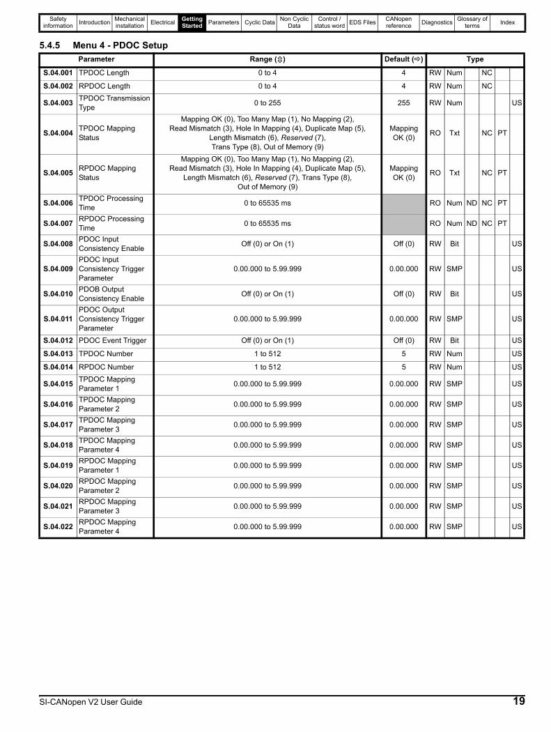
5.4.5 Menu 4 - PDOC SetupParameter Range () Default () Type
S.04.001 TPDOC Length 0 to 4 4 RW Num NC
S.04.002 RPDOC Length 0 to 4 4 RW Num NC
S.04.003 TPDOC Transmission Type 0 to 255 255 RW Num US
S.04.004 TPDOC Mapping Status
Mapping OK (0), Too Many Map (1), No Mapping (2), Read Mismatch (3), Hole In Mapping (4), Duplicate Map (5),
Length Mismatch (6), Reserved (7), Trans Type (8), Out of Memory (9)
Mapping OK (0) RO Txt NC PT
S.04.005 RPDOC Mapping Status
Mapping OK (0), Too Many Map (1), No Mapping (2), Read Mismatch (3), Hole In Mapping (4), Duplicate Map (5),
Length Mismatch (6), Reserved (7), Trans Type (8), Out of Memory (9)
Mapping OK (0) RO Txt NC PT
S.04.006 TPDOC Processing Time 0 to 65535 ms RO Num ND NC PT
S.04.007 RPDOC Processing Time 0 to 65535 ms RO Num ND NC PT
S.04.008 PDOC Input Consistency Enable Off (0) or On (1) Off (0) RW Bit US
S.04.009PDOC Input Consistency Trigger Parameter
0.00.000 to 5.99.999 0.00.000 RW SMP US
S.04.010 PDOB Output Consistency Enable Off (0) or On (1) Off (0) RW Bit US
S.04.011PDOC Output Consistency Trigger Parameter
0.00.000 to 5.99.999 0.00.000 RW SMP US
S.04.012 PDOC Event Trigger Off (0) or On (1) Off (0) RW Bit US
S.04.013 TPDOC Number 1 to 512 5 RW Num US
S.04.014 RPDOC Number 1 to 512 5 RW Num US
S.04.015 TPDOC Mapping Parameter 1 0.00.000 to 5.99.999 0.00.000 RW SMP US
S.04.016 TPDOC Mapping Parameter 2 0.00.000 to 5.99.999 0.00.000 RW SMP US
S.04.017 TPDOC Mapping Parameter 3 0.00.000 to 5.99.999 0.00.000 RW SMP US
S.04.018 TPDOC Mapping Parameter 4 0.00.000 to 5.99.999 0.00.000 RW SMP US
S.04.019 RPDOC Mapping Parameter 1 0.00.000 to 5.99.999 0.00.000 RW SMP US
S.04.020 RPDOC Mapping Parameter 2 0.00.000 to 5.99.999 0.00.000 RW SMP US
S.04.021 RPDOC Mapping Parameter 3 0.00.000 to 5.99.999 0.00.000 RW SMP US
S.04.022 RPDOC Mapping Parameter 4 0.00.000 to 5.99.999 0.00.000 RW SMP US
SI-CANopen V2 User Guide 19

Safety information Introduction Mechanical
installation Electrical Getting Started Parameters Cyclic Data Non Cyclic
DataControl /
status word EDS Files CANopen reference Diagnostics Glossary of
terms Index
5.4.6 Menu 5 - PDOD SetupParameter Range () Default () Type
S.05.001 TPDOD Length 0 to 4 4 RW Num NC
S.05.002 RPDOD Length 0 to 4 4 RW Num NC
S.05.003 TPDOD Transmission Type 0 to 255 255 RW Num
US
S.05.004 TPDOD Mapping Status
Mapping OK (0), Too Many Map (1), No Mapping (2), Read Mismatch (3), Hole In Mapping (4), Duplicate Map (5),
Length Mismatch (6), Reserved (7), Trans Type (8), Out of Memory (9)
Mapping OK (0) RO Txt NC PT
S.05.005 RPDOD Mapping Status
Mapping OK (0), Too Many Map (1), No Mapping (2), Read Mismatch (3), Hole In Mapping (4), Duplicate Map (5),
Length Mismatch (6), Reserved (7), Trans Type (8), Out of Memory (9)
Mapping OK (0) RO Txt NC PT
S.05.006 TPDOD Processing Time 0 to 65535 ms RO Num ND NC PT
S.05.007 RPDOD Processing Time 0 to 65535 ms RO Num ND NC PT
S.05.008 PDOD Input Consistency Enable Off (0) or On (1) Off (0) RW Bit US
S.05.009 PDOD Input Consistency Trigger Parameter 0.00.000 to 5.99.999 0.00.000 RW SMP US
S.05.010 PDOD Output Consistency Enable Off (0) or On (1) Off (0) RW Bit US
S.05.011 PDOD Output Consistency Trigger Parameter
0.00.000 to 5.99.999 0.00.000 RW SMP US
S.05.012 PDOD Event Trigger Off (0) or On (1) Off (0) RW Bit US
S.05.013 TPDOD Number 1 to 512 6 RW Num US
S.05.014 RPDOD Number 1 to 512 6 RW Num US
S.05.015 TPDOD Mapping Parameter 1 0.00.000 to 5.99.999 0.00.000 RW SMP US
S.05.016 TPDOD Mapping Parameter 2 0.00.000 to 5.99.999 0.00.000 RW SMP US
S.05.017 TPDOD Mapping Parameter 3 0.00.000 to 5.99.999 0.00.000 RW SMP US
S.05.018 TPDOD Mapping Parameter 4 0.00.000 to 5.99.999 0.00.000 RW SMP US
S.05.019 RPDOD Mapping Parameter 1 0.00.000 to 5.99.999 0.00.000 RW SMP US
S.05.020 RPDOD Mapping Parameter 2 0.00.000 to 5.99.999 0.00.000 RW SMP US
S.05.021 RPDOD Mapping Parameter 3 0.00.000 to 5.99.999 0.00.000 RW SMP US
S.05.022 RPDOD Mapping Parameter 4 0.00.000 to 5.99.999 0.00.000 RW SMP US
20 SI-CANopen V2 User Guide
Safety information Introduction Mechanical
installation Electrical Getting Started Parameters Cyclic Data Non Cyclic
DataControl /
status word EDS Files CANopen reference Diagnostics Glossary of
terms Index
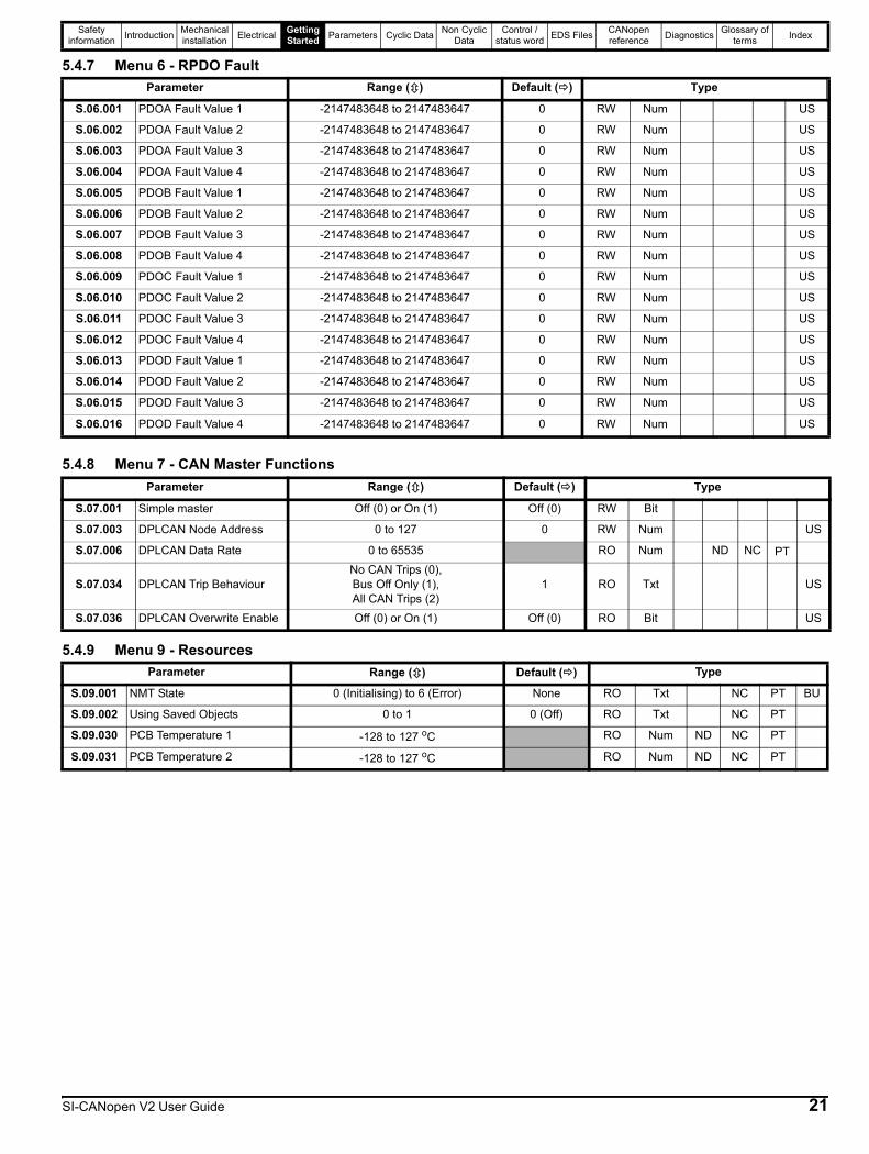
5.4.7 Menu 6 - RPDO Fault
5.4.8 Menu 7 - CAN Master Functions
5.4.9 Menu 9 - Resources
Parameter Range () Default () Type
S.06.001 PDOA Fault Value 1 -2147483648 to 2147483647 0 RW Num US
S.06.002 PDOA Fault Value 2 -2147483648 to 2147483647 0 RW Num US
S.06.003 PDOA Fault Value 3 -2147483648 to 2147483647 0 RW Num US
S.06.004 PDOA Fault Value 4 -2147483648 to 2147483647 0 RW Num US
S.06.005 PDOB Fault Value 1 -2147483648 to 2147483647 0 RW Num US
S.06.006 PDOB Fault Value 2 -2147483648 to 2147483647 0 RW Num US
S.06.007 PDOB Fault Value 3 -2147483648 to 2147483647 0 RW Num US
S.06.008 PDOB Fault Value 4 -2147483648 to 2147483647 0 RW Num US
S.06.009 PDOC Fault Value 1 -2147483648 to 2147483647 0 RW Num US
S.06.010 PDOC Fault Value 2 -2147483648 to 2147483647 0 RW Num US
S.06.011 PDOC Fault Value 3 -2147483648 to 2147483647 0 RW Num US
S.06.012 PDOC Fault Value 4 -2147483648 to 2147483647 0 RW Num US
S.06.013 PDOD Fault Value 1 -2147483648 to 2147483647 0 RW Num US
S.06.014 PDOD Fault Value 2 -2147483648 to 2147483647 0 RW Num US
S.06.015 PDOD Fault Value 3 -2147483648 to 2147483647 0 RW Num US
S.06.016 PDOD Fault Value 4 -2147483648 to 2147483647 0 RW Num US
Parameter Range () Default () Type
S.07.001 Simple master Off (0) or On (1) Off (0) RW Bit
S.07.003 DPLCAN Node Address 0 to 127 0 RW Num US
S.07.006 DPLCAN Data Rate 0 to 65535 RO Num ND NC PT
S.07.034 DPLCAN Trip BehaviourNo CAN Trips (0), Bus Off Only (1), All CAN Trips (2)
1 RO Txt US
S.07.036 DPLCAN Overwrite Enable Off (0) or On (1) Off (0) RO Bit US
Parameter Range () Default () Type
S.09.001 NMT State 0 (Initialising) to 6 (Error) None RO Txt NC PT BU
S.09.002 Using Saved Objects 0 to 1 0 (Off) RO Txt NC PT
S.09.030 PCB Temperature 1 -128 to 127 oC RO Num ND NC PT
S.09.031 PCB Temperature 2 -128 to 127 oC RO Num ND NC PT
SI-CANopen V2 User Guide 21

Safety information Introduction Mechanical
installation Electrical Getting Started Parameters Cyclic Data Non Cyclic
DataControl /
status word EDS Files CANopen reference Diagnostics Glossary of
terms Index
5.5 PDO number configurationSI-CANopen V2 provides four TxPDOs and four RxPDOs, these are referred to as PDOs A, B, C & D. By default these are configured as PDOs 1, 3, 5 & 6 respectively.
If a controller/PLC requires PDO numbering to be changed (e.g. the only supported PDOs are 1,2,3 and 4), this can be achieved using object 0x2800 or 0x2801, doing this will result in the existing PDO configuration objects being destroyed and objects for the new PDO being created with default values, this will take effect immediately. If the PDO number is already used within the same object the old PDO will be overwritten. It is now possible to have different numbers for individual TxPDOs and RxPDOs eg. TxPDO 1, 2, 3, 4 and RxPDO 5, 6, 7 and 8.
5.5.1 Object 0x2800 (RxPDO number configuration)Sub Index 0 : Will return 4 when read indicating the maximum sub-index and number of PDOs supported.
Sub Index 1 – 4 : Are used to read and set the RxPDO number for each of the four configurable RxPDOs. The number is specified as the required number less 1. That is, PDO1 would be represented as 0.
5.5.2 Object 0x2801 (TxPDO number configuration)Sub Index 0: Will return 4 when read indicating the maximum sub-index and number of PDOs supported.
Sub Index 1 – 4: Are used to read and set the TxPDO number for each of the four configurable TxPDOs. The actual index number is calculated by subtracting 1 from the PDO number and adding this number to the base address (e.g. for PDO3 use 2).
5.6 PDO structure (PDOs A, B, C & D)SI-CANopen V2 provides four TxPDOs and four RxPDOs, these are referred to as PDOs A, B, C & D. By default these are configured as PDOs 1, 3, 5 & 6 respectively.
All PDOs may be configured entirely from the module’s parameters without the need for a master. All PDOs can also be set up using SDOs from the master.
The benefits of using this scheme are that it allows the four PDOs (A, B, C and D) to be configured to any valid PDO number required while still achieving conformance.
5.7 Types of set-upSI-CANopen V2 offers two methods of configuring the PDOs, either entirely from the SI-CANopen V2 menus (S.01.008 = By Menu) or using SDO messages from the master/controller (S.01.008 = By Master).
For configuring the PDO numbers from the module's parameters, each PDO (A, B, C and D) has its own menu structure, Table 5-1 shows the parameters required to change the PDO numbering from the drive menus.
Table 5-1 SI-CANopen V2 PDO Flexible numbering parameters
This will result in the existing PDO configuration objects being destroyed and objects for the new PDO being created with the configured values, this will take effect immediately. If the PDO number is already used within the same object the old PDO will be overwritten.
5.7.1 Configuration by SI-CANopen V2 parameters only (No master/controller)Any PDO (A, B, C, D) may be configured by just using the SI-CANopen V2 parameters, all communication settings (such as PDO number, transmission type, PDO length and mappings) may be configured directly from the SI-CANopen V2 parameters.The SI-CANopen V2 menus for the relevant PDOs are shown in the following table.
Configuring the PDOs from the SI-CANopen V2 module parameters allows the full range of PDO numbers (1 to 512) being used, the PDO communication and mapping parameters configuration SDO objects only support PDO numbers 1 to 16 as shown in the following section.
PDO Default NumberParameter
TxPDO RxPDO
A 1 S.02.013 S.02.014
B 3 S.03.013 S.03.014
C 5 S.04.013 S.04.014
D 6 S.05.013 S.05.014
PDO Menu
A 2
B 3
C 4
D 5
The default transmission type, asynchronous timer trigger (type 255) for TxPDOA cannot be configured without a controller/PLC, as the SI-CANopen V2 internal timer must be configured to use this feature. For use without a controller/PLC the transmission type should be changed. This default configuration prevents a partially configured node from transmitting on the network.
NOTE
22 SI-CANopen V2 User Guide

Safety information Introduction Mechanical
installation Electrical Getting Started Parameters Cyclic Data Non Cyclic
DataControl /
status word EDS Files CANopen reference Diagnostics Glossary of
terms Index
5.7.2 Configuration by CANopen master/controller via SDOsSI-CANopen V2 provides the ability to configure any PDO to any one of sixteen PDO numbers (1 to 16) when using SDOs to configure the PDO communication and mapping parameters. Any PDO (A, B, C, D) may be configured by the CANopen master/controller using SDOs, all communication settings (such as PDO number, transmission type, PDO length and mappings) may be configured using the relevant object reference for the numbered PDO.
The required PDO number and related objects are shown in the following table.
5.7.3 Flexible PDO numbering (master required)SI-CANopen V2 provides a method of reconfiguring the available PDOs while still maintaining conformance (objects 0x2800 and 0x2801). This method allows four TxPDOs (A, B, C & D) and four RxPDOs (A, B, C & D) to be configured individually to any valid PDO number. It is not necessary for the TxPDOs and RxPDOs to have the same PDO numbers, thus allowing for absolute flexibility during configuration. The configuration objects for the configured PDOs are taken from the base address of the object (eg. 0x1800) plus the configured PDO number minus 1 (e.g. TxPDO2 would use 0x1801).
5.7.4 SDO savingA method for saving the configured PDOs is available by using object (0x1010), which allows all communication settings to be stored in the SI-CANopen V2 module. This allows SI-CANopen V2 to retain the settings sent by the configuration SDOs from the controller/PLC. The node is then able to resume communications without requiring the SDO configuration to be re-sent by the controller/PLC, following a reset or loss of power. This procedure also forces a parameter save in the SI-CANopen V2 module.
5.7.5 Pre-configuration for a machine (controller/PLC required initially)The SDO saving option (0x1010) allows SI-CANopen V2 to be pre-configured on a controller/PLC before use on a system. This allows the product to be configured for use with a controller/PLC that does not support SDO configuration of the slave device, or a controller/PLC that requires a specific set of PDO numbers. This effectively allows the module to be pre-configured before installation and allows SI-CANopen V2 to work in existing hardware configurations with different PDO numbering schemes.
NumberRxPDO TxPDO
Communication Mapping Communication Mapping
1(PDOA default)
0x1400 0x1600 0x1800 0x1A00
2 0x1401 0x1601 0x1801 0x1A01
3(PDOB default)
0x1402 0x1602 0x1802 0x1A02
4 0x1403 0x1603 0x1803 0x1A03
5(PDOC default)
0x1404 0x1604 0x1804 0x1A04
6(PDOD default)
0x1405 0x1605 0x1805 0x1A05
7 0x1406 0x1606 0x1806 0x1A06
8 0x1407 0x1607 0x1807 0x1A07
9 0x1408 0x1608 0x1808 0x1A08
10 0x1409 0x1609 0x1809 0x1A09
11 0x140A 0x160A 0x180A 0x1A0A
12 0x140B 0x160B 0x180B 0x1A0B
13 0x140C 0x160C 0x180C 0x1A0C
14 0x140D 0x160D 0x180D 0x1A0D
15 0x140E 0x160E 0x180E 0x1A0E
16 0x140F 0x160F 0x180F 0x1A0F
If an SDO overwrites the settings made in the module’s parameters, then the values for the communication objects will be changed. However, the values stored in the parameters will not be altered.
NOTE
SI-CANopen V2 User Guide 23
Safety information Introduction Mechanical
installation Electrical Getting Started Parameters Cyclic Data Non Cyclic
DataControl /
status word EDS Files CANopen reference Diagnostics Glossary of
terms Index
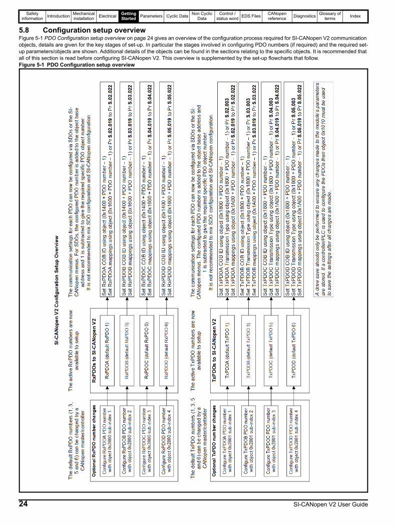
5.8 Configuration setup overviewFigure 5-1 PDO Configuration setup overview on page 24 gives an overview of the configuration process required for SI-CANopen V2 communication objects, details are given for the key stages of set-up. In particular the stages involved in configuring PDO numbers (if required) and the required set-up parameters/objects are shown. Additional details of the objects can be found in the sections relating to the specific objects. It is recommended that all of this section is read before configuring SI-CANopen V2. This overview is supplemented by the set-up flowcharts that follow.Figure 5-1 PDO Configuration setup overview
24 SI-CANopen V2 User Guide
Safety information Introduction Mechanical
installation Electrical Getting Started Parameters Cyclic Data Non Cyclic
DataControl /
status word EDS Files CANopen reference Diagnostics Glossary of
terms Index
5.9 Setup flowchartsThe following flowcharts should be used as a visual reference to aid with the configuration of a network. Various options are highlighted by decision boxes and sub flowcharts are used to extend the detail within certain sections.
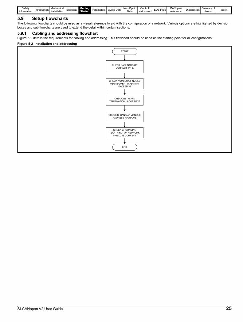
5.9.1 Cabling and addressing flowchartFigure 5-2 details the requirements for cabling and addressing. This flowchart should be used as the starting point for all configurations.
Figure 5-2 Installation and addressing
START
CHECK CABLING IS OF CORRECT TYPE
CHECK NUMBER OF NODES PER SEGMENT DOES NOT
EXCEED 32
CHECK NETWORK TERMINATION IS CORRECT
CHECK SI-CANopen V2 NODE ADDRESS IS UNIQUE
CHECK GROUNDING (EARTHING) OF NETWORK
SHIELD IS CORRECT
END
SI-CANopen V2 User Guide 25
Safety information Introduction Mechanical
installation Electrical Getting Started Parameters Cyclic Data Non Cyclic
DataControl /
status word EDS Files CANopen reference Diagnostics Glossary of
terms Index
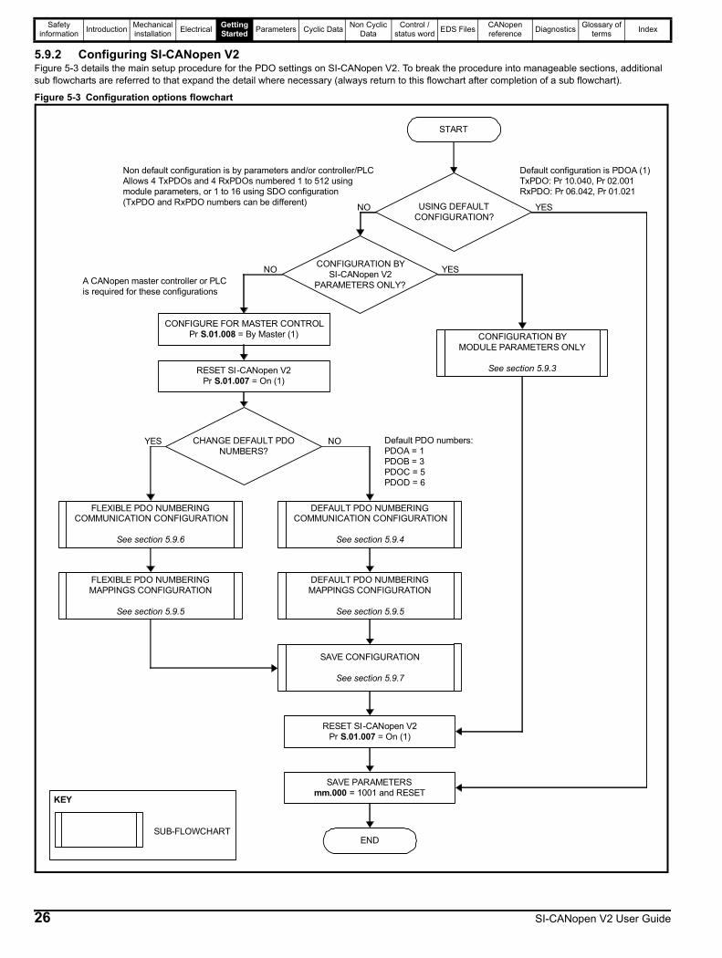
5.9.2 Configuring SI-CANopen V2Figure 5-3 details the main setup procedure for the PDO settings on SI-CANopen V2. To break the procedure into manageable sections, additional sub flowcharts are referred to that expand the detail where necessary (always return to this flowchart after completion of a sub flowchart). Figure 5-3 Configuration options flowchart
START
END
Non default configuration is by parameters and/or controller/PLCAllows 4 TxPDOs and 4 RxPDOs numbered 1 to 512 using module parameters, or 1 to 16 using SDO configuration(TxPDO and RxPDO numbers can be different)
SAVE PARAMETERSmm.000 = 1001 and RESET
RESET SI-CANopen V2Pr S.01.007 = On (1)
CONFIGURE FOR MASTER CONTROLPr S.01.008 = By Master (1)
A CANopen master controller or PLC is required for these configurations
RESET SI-CANopen V2Pr S.01.007 = On (1)
CONFIGURATION BYMODULE PARAMETERS ONLY
See section 5.9.3
USING DEFAULT CONFIGURATION?
NO YES
CONFIGURATION BYSI-CANopen V2
PARAMETERS ONLY?
YESNO
CHANGE DEFAULT PDO NUMBERS?
YES NO Default PDO numbers:PDOA = 1PDOB = 3PDOC = 5PDOD = 6
DEFAULT PDO NUMBERING COMMUNICATION CONFIGURATION
See section 5.9.4
DEFAULT PDO NUMBERING MAPPINGS CONFIGURATION
See section 5.9.5
SAVE CONFIGURATION
See section 5.9.7
Default configuration is PDOA (1)TxPDO: Pr 10.040, Pr 02.001RxPDO: Pr 06.042, Pr 01.021
FLEXIBLE PDO NUMBERING COMMUNICATION CONFIGURATION
See section 5.9.6
FLEXIBLE PDO NUMBERING MAPPINGS CONFIGURATION
See section 5.9.5
KEY
SUB-FLOWCHART
26 SI-CANopen V2 User Guide
Safety information Introduction Mechanical
installation Electrical Getting Started Parameters Cyclic Data Non Cyclic
DataControl /
status word EDS Files CANopen reference Diagnostics Glossary of
terms Index
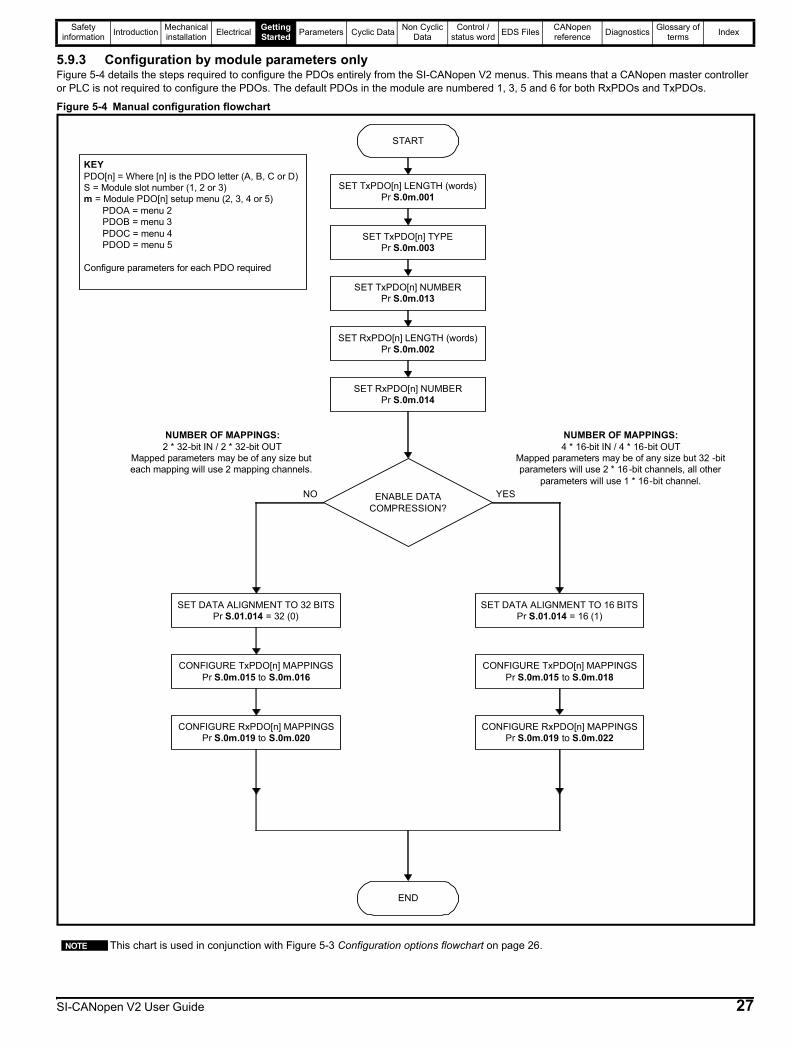
5.9.3 Configuration by module parameters onlyFigure 5-4 details the steps required to configure the PDOs entirely from the SI-CANopen V2 menus. This means that a CANopen master controller or PLC is not required to configure the PDOs. The default PDOs in the module are numbered 1, 3, 5 and 6 for both RxPDOs and TxPDOs.
Figure 5-4 Manual configuration flowchart
This chart is used in conjunction with Figure 5-3 Configuration options flowchart on page 26.
START
NUMBER OF MAPPINGS:2 * 32-bit IN / 2 * 32-bit OUT
Mapped parameters may be of any size but each mapping will use 2 mapping channels.
CONFIGURE TxPDO[n] MAPPINGSPr S.0m.015 to S.0m.016
END
SET TxPDO[n] LENGTH (words)Pr S.0m.001
SET TxPDO[n] TYPEPr S.0m.003
SET TxPDO[n] NUMBERPr S.0m.013
ENABLE DATA COMPRESSION?
YESNO
SET RxPDO[n] LENGTH (words)Pr S.0m.002
SET RxPDO[n] NUMBERPr S.0m.014
SET DATA ALIGNMENT TO 32 BITSPr S.01.014 = 32 (0)
CONFIGURE RxPDO[n] MAPPINGSPr S.0m.019 to S.0m.020
KEYPDO[n] = Where [n] is the PDO letter (A, B, C or D)S = Module slot number (1, 2 or 3)m = Module PDO[n] setup menu (2, 3, 4 or 5) PDOA = menu 2 PDOB = menu 3 PDOC = menu 4
PDOD = menu 5
Configure parameters for each PDO required
NUMBER OF MAPPINGS:4 * 16-bit IN / 4 * 16-bit OUT
Mapped parameters may be of any size but 32 -bit parameters will use 2 * 16-bit channels, all other
parameters will use 1 * 16-bit channel.
CONFIGURE TxPDO[n] MAPPINGSPr S.0m.015 to S.0m.018
SET DATA ALIGNMENT TO 16 BITSPr S.01.014 = 16 (1)
CONFIGURE RxPDO[n] MAPPINGSPr S.0m.019 to S.0m.022
NOTE
SI-CANopen V2 User Guide 27
Safety information Introduction Mechanical
installation Electrical Getting Started Parameters Cyclic Data Non Cyclic
DataControl /
status word EDS Files CANopen reference Diagnostics Glossary of
terms Index
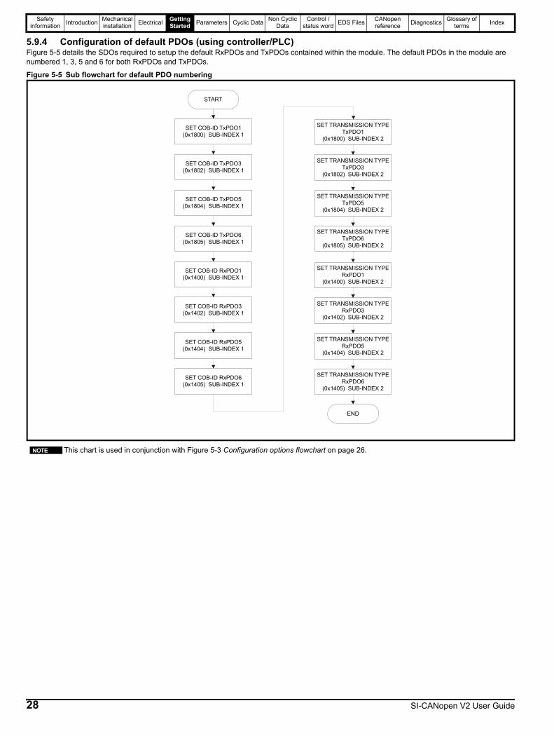
5.9.4 Configuration of default PDOs (using controller/PLC)Figure 5-5 details the SDOs required to setup the default RxPDOs and TxPDOs contained within the module. The default PDOs in the module are numbered 1, 3, 5 and 6 for both RxPDOs and TxPDOs.
Figure 5-5 Sub flowchart for default PDO numbering
SET TRANSMISSION TYPE TxPDO1
(0x1800) SUB-INDEX 2
SET COB-ID RxPDO6(0x1405) SUB-INDEX 1
SET COB-ID RxPDO3(0x1402) SUB-INDEX 1
SET COB-ID RxPDO1(0x1400) SUB-INDEX 1
SET COB-ID TxPDO6(0x1805) SUB-INDEX 1
SET COB-ID TxPDO3(0x1802) SUB-INDEX 1
SET COB-ID RxPDO5(0x1404) SUB-INDEX 1
SET COB-ID TxPDO5(0x1804) SUB-INDEX 1
SET TRANSMISSION TYPE TxPDO3
(0x1802) SUB-INDEX 2
SET TRANSMISSION TYPE RxPDO5
(0x1404) SUB-INDEX 2
SET TRANSMISSION TYPE RxPDO3
(0x1402) SUB-INDEX 2
SET TRANSMISSION TYPE RxPDO1
(0x1400) SUB-INDEX 2
SET TRANSMISSION TYPE TxPDO5
(0x1804) SUB-INDEX 2
SET TRANSMISSION TYPE RxPDO6
(0x1405) SUB-INDEX 2
SET TRANSMISSION TYPE TxPDO6
(0x1805) SUB-INDEX 2
SET COB-ID TxPDO1(0x1800) SUB-INDEX 1
START
END
This chart is used in conjunction with Figure 5-3 Configuration options flowchart on page 26.NOTE
28 SI-CANopen V2 User Guide

Safety information Introduction Mechanical
installation Electrical Getting Started Parameters Cyclic Data Non Cyclic
DataControl /
status word EDS Files CANopen reference Diagnostics Glossary of
terms Index
5.9.5 Mapping Configuration of PDOsFigure 5-6 shows the configuration of the mappings for PDOs. This is performed using the SDOs shown below. The route through this flowchart will be determined by the size of the parameters that are mapped.
Figure 5-6 Mapping Configuration Flowchart [1]
This chart is used in conjunction with Figure 5-3 Configuration options flowchart on page 26. Setting Pr S.01.014 to 1 (data alignment on) will allow a maximum of four mappings. If data compression is off, or the parameters are 32 bits, then only two mappings will be possible (i.e. each PDO has 64 bits, so the size of the parameters mapped will determine the maximum number of mappings). PDOs A, B, C & D may be configured to any valid PDO number and the TxPDO and RxPDO numbers are independent. The default configuration for PDOA, B, C & D are PDO numbers 1, 3, 5 & 6 respectively.
START
NUMBER OF MAPPINGS PER PDO2 * 32-bit IN / 2 * 32-bit OUT
Mapped parameters may be of any size buteach mapping will use 2 mapping channels.
SET TxPDO[n] LENGTH (words)
Pr S.0m.001
SET TxPDO[n] TYPEPr S.0m.003
SET TxPDO[n] NUMBER
Pr S.0m.013
YESNO
SET RxPDO[n] LENGTH (words)Pr S.0m.002
SET RxPDO[n] NUMBER
Pr S.0m.014
SET DATA ALIGNMENT TO 32 BITSPr S.01.014 = 32 (0)
KEY
PDO[n] = Where [n] is the PDO letter (A, B, C or D)
S = Module slot number (1, 2 or 3)m = Module PDO[n] setup menu (2, 3, 4 or 5)
PDOA = menu 2PDOB = menu 3
PDOC = menu 4PDOD = menu 5
{} = Default PDO number
NUMBER OF MAPPINGS PER PDO4 * 16-bit IN / 4 * 16-bit OUT
Mapped parameters may be of any size but32-bit parameters will use 2 * 16-bit
channels, all other parameters will use 1 *16-bit channel.
SET DATA ALIGNMENT TO 16 BITSPr S.01.014 = 16 (1)
NOTES� Configure parameters for each PDO required� Mappings configured by SDO commands will
erase and re-configure any existing mappings
configured by SI-CANopen V2 parameters� PDO object index number is derived from the
base address plus the PDO number less 1
(default PDO numbers shown)
MAXIMUM NUMBER OF MAPPINGS
4 PDOs of 2 mappings = 8 parameters MAXIMUM NUMBER OF MAPPINGS4 PDOs of 4 mappings = 16 parameters
CLEAR CURRENT MAPPINGS
0x1600, sub-index 0 = 0
CONFIGURE FIRST MAPPING0x1600, sub-index 1
CONFIGURE SECOND MAPPING
0x1600, sub-index 2
SET NUMBER OF MAPPINGS0x1600, sub-index 0 = 2
RxPDOA {1}
ENABLE DATACOMPRESSION?
A
CLEAR CURRENT MAPPINGS0x1602, sub-index 0 = 0
CONFIGURE FIRST MAPPING
0x1602, sub-index 1
CONFIGURE SECOND MAPPING
0x1602, sub-index 2
SET NUMBER OF MAPPINGS
0x1602, sub-index 0 = 2
RxPDOB {3}
Continued on next page
CLEAR CURRENT MAPPINGS
0x1600, sub-index 0 = 0
CONFIGURE FIRST MAPPING0x1600, sub-index 1
CONFIGURE SECOND MAPPING
0x1600, sub-index 2
SET NUMBER OF MAPPINGS0x1600, sub-index 0 = 4
RxPDOA {1}
CONFIGURE THIRD MAPPING0x1600, sub-index 3
CONFIGURE FOURTH MAPPING
0x1600, sub-index 4
B
Continued on next page
CLEAR CURRENT MAPPINGS
0x1602, sub-index 0 = 0
CONFIGURE FIRST MAPPING
0x1602, sub-index 1
RxPDOB {3}
NOTE
SI-CANopen V2 User Guide 29
Safety information Introduction Mechanical
installation Electrical Getting Started Parameters Cyclic Data Non Cyclic
DataControl /
status word EDS Files CANopen reference Diagnostics Glossary of
terms Index
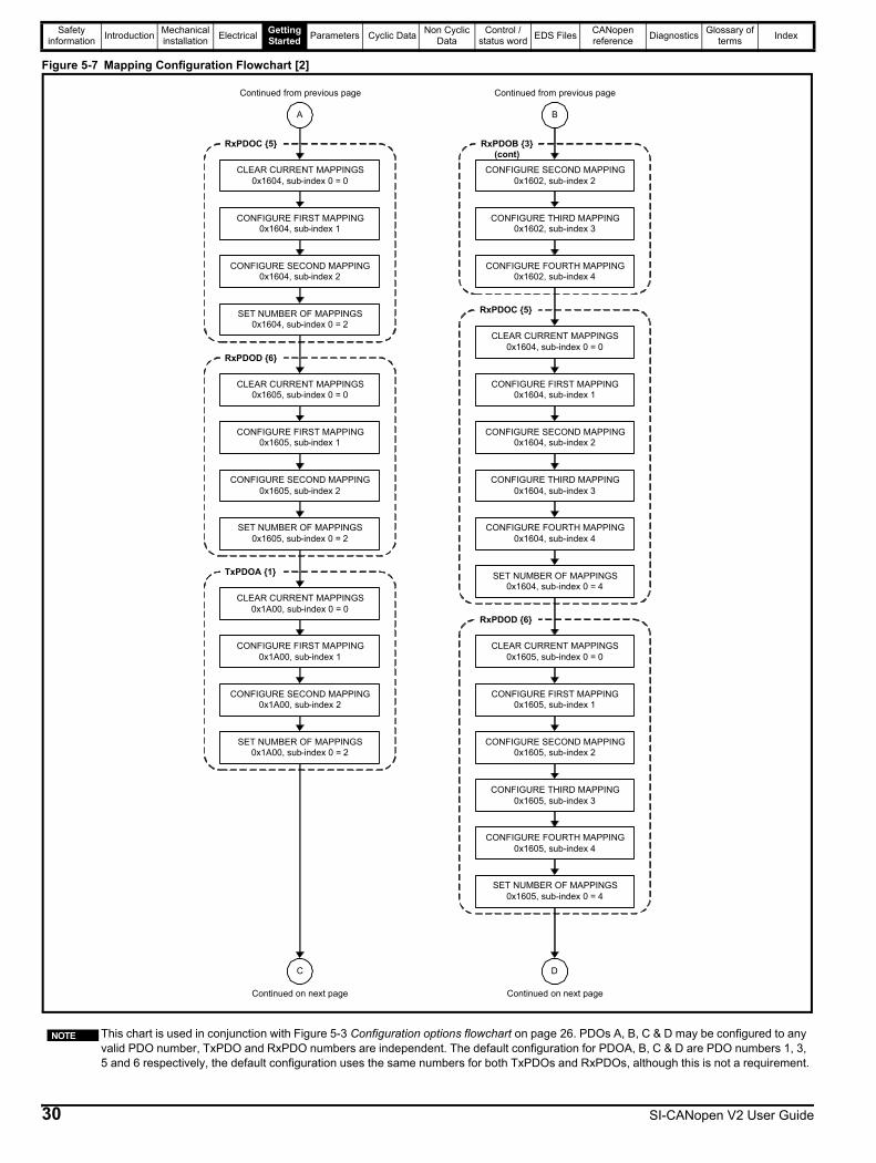
Figure 5-7 Mapping Configuration Flowchart [2]
This chart is used in conjunction with Figure 5-3 Configuration options flowchart on page 26. PDOs A, B, C & D may be configured to any valid PDO number, TxPDO and RxPDO numbers are independent. The default configuration for PDOA, B, C & D are PDO numbers 1, 3, 5 and 6 respectively, the default configuration uses the same numbers for both TxPDOs and RxPDOs, although this is not a requirement.
CLEAR CURRENT MAPPINGS0x1604, sub-index 0 = 0
CONFIGURE FIRST MAPPING0x1604, sub-index 1
CONFIGURE SECOND MAPPING0x1604, sub-index 2
SET NUMBER OF MAPPINGS0x1604, sub-index 0 = 2
RxPDOC {5}
CLEAR CURRENT MAPPINGS0x1605, sub-index 0 = 0
CONFIGURE FIRST MAPPING0x1605, sub-index 1
CONFIGURE SECOND MAPPING0x1605, sub-index 2
SET NUMBER OF MAPPINGS0x1605, sub-index 0 = 2
RxPDOD {6}
Continued on next page
CONFIGURE SECOND MAPPING0x1602, sub-index 2
CONFIGURE THIRD MAPPING0x1602, sub-index 3
CONFIGURE FOURTH MAPPING0x1602, sub-index 4
RxPDOB {3} (cont)
D
Continued on next page
A
Continued from previous page
B
Continued from previous page
CLEAR CURRENT MAPPINGS0x1604, sub-index 0 = 0
CONFIGURE FIRST MAPPING0x1604, sub-index 1
CONFIGURE SECOND MAPPING0x1604, sub-index 2
SET NUMBER OF MAPPINGS0x1604, sub-index 0 = 4
RxPDOC {5}
CONFIGURE THIRD MAPPING0x1604, sub-index 3
CONFIGURE FOURTH MAPPING0x1604, sub-index 4
CLEAR CURRENT MAPPINGS0x1A00, sub-index 0 = 0
CONFIGURE FIRST MAPPING0x1A00, sub-index 1
CONFIGURE SECOND MAPPING0x1A00, sub-index 2
SET NUMBER OF MAPPINGS0x1A00, sub-index 0 = 2
TxPDOA {1}
C
CLEAR CURRENT MAPPINGS0x1605, sub-index 0 = 0
CONFIGURE FIRST MAPPING0x1605, sub-index 1
CONFIGURE SECOND MAPPING0x1605, sub-index 2
SET NUMBER OF MAPPINGS0x1605, sub-index 0 = 4
RxPDOD {6}
CONFIGURE THIRD MAPPING0x1605, sub-index 3
CONFIGURE FOURTH MAPPING0x1605, sub-index 4
NOTE
30 SI-CANopen V2 User Guide
Safety information Introduction Mechanical
installation Electrical Getting Started Parameters Cyclic Data Non Cyclic
DataControl /
status word EDS Files CANopen reference Diagnostics Glossary of
terms Index
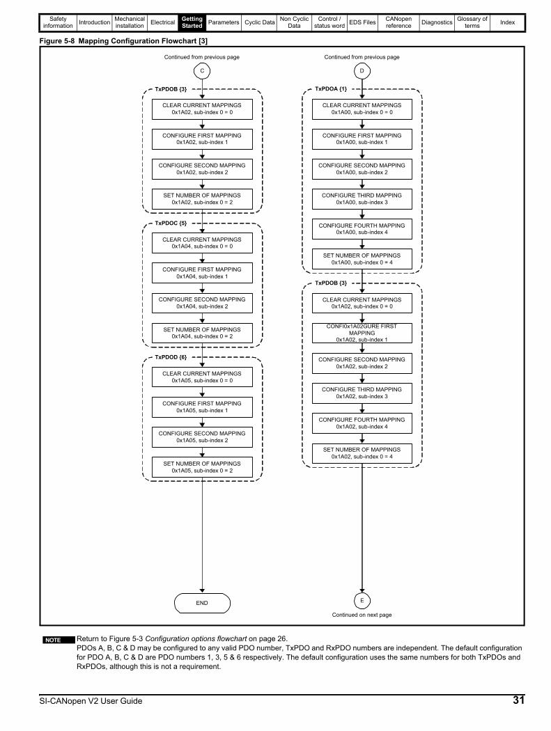
Figure 5-8 Mapping Configuration Flowchart [3]
Return to Figure 5-3 Configuration options flowchart on page 26. PDOs A, B, C & D may be configured to any valid PDO number, TxPDO and RxPDO numbers are independent. The default configuration for PDO A, B, C & D are PDO numbers 1, 3, 5 & 6 respectively. The default configuration uses the same numbers for both TxPDOs and RxPDOs, although this is not a requirement.
END
CLEAR CURRENT MAPPINGS0x1A02, sub-index 0 = 0
CONFIGURE FIRST MAPPING0x1A02, sub-index 1
CONFIGURE SECOND MAPPING0x1A02, sub-index 2
SET NUMBER OF MAPPINGS0x1A02, sub-index 0 = 2
TxPDOB {3}
CLEAR CURRENT MAPPINGS0x1A04, sub-index 0 = 0
CONFIGURE FIRST MAPPING0x1A04, sub-index 1
CONFIGURE SECOND MAPPING0x1A04, sub-index 2
SET NUMBER OF MAPPINGS0x1A04, sub-index 0 = 2
TxPDOC {5}
CLEAR CURRENT MAPPINGS0x1A00, sub-index 0 = 0
CONFIGURE FIRST MAPPING0x1A00, sub-index 1
CONFIGURE SECOND MAPPING0x1A00, sub-index 2
SET NUMBER OF MAPPINGS0x1A00, sub-index 0 = 4
TxPDOA {1}
CONFIGURE THIRD MAPPING0x1A00, sub-index 3
CONFIGURE FOURTH MAPPING0x1A00, sub-index 4
E
Continued on next page
C
Continued from previous page
D
Continued from previous page
CLEAR CURRENT MAPPINGS0x1A02, sub-index 0 = 0
CONFI0x1A02GURE FIRST MAPPING
0x1A02, sub-index 1
CONFIGURE SECOND MAPPING0x1A02, sub-index 2
SET NUMBER OF MAPPINGS0x1A02, sub-index 0 = 4
TxPDOB {3}
CONFIGURE THIRD MAPPING0x1A02, sub-index 3
CONFIGURE FOURTH MAPPING0x1A02, sub-index 4
CLEAR CURRENT MAPPINGS0x1A05, sub-index 0 = 0
CONFIGURE FIRST MAPPING0x1A05, sub-index 1
CONFIGURE SECOND MAPPING0x1A05, sub-index 2
SET NUMBER OF MAPPINGS0x1A05, sub-index 0 = 2
TxPDOD {6}
NOTE
SI-CANopen V2 User Guide 31
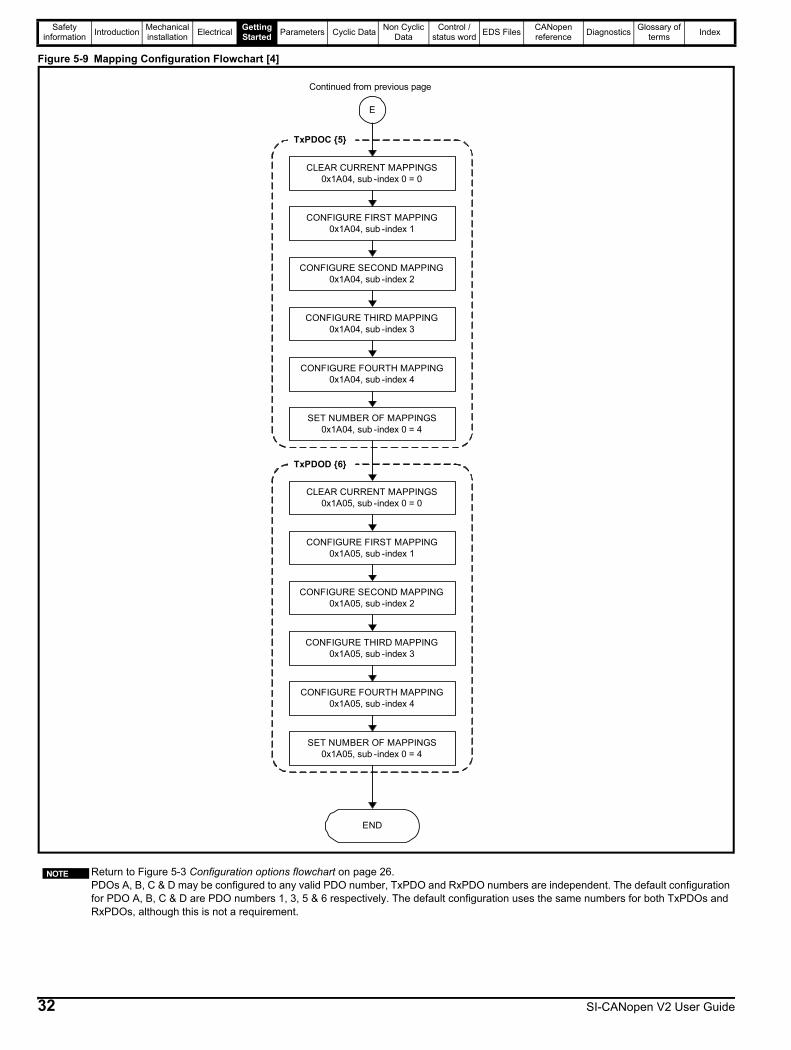
Safety information Introduction Mechanical
installation Electrical Getting Started Parameters Cyclic Data Non Cyclic
DataControl /
status word EDS Files CANopen reference Diagnostics Glossary of
terms Index
Figure 5-9 Mapping Configuration Flowchart [4]
Return to Figure 5-3 Configuration options flowchart on page 26. PDOs A, B, C & D may be configured to any valid PDO number, TxPDO and RxPDO numbers are independent. The default configuration for PDO A, B, C & D are PDO numbers 1, 3, 5 & 6 respectively. The default configuration uses the same numbers for both TxPDOs and RxPDOs, although this is not a requirement.
END
CLEAR CURRENT MAPPINGS0x1A04, sub -index 0 = 0
CONFIGURE FIRST MAPPING0x1A04, sub -index 1
CONFIGURE SECOND MAPPING0x1A04, sub -index 2
SET NUMBER OF MAPPINGS0x1A04, sub -index 0 = 4
TxPDOC {5}
CONFIGURE THIRD MAPPING0x1A04, sub -index 3
CONFIGURE FOURTH MAPPING0x1A04, sub -index 4
E
Continued from previous page
CLEAR CURRENT MAPPINGS0x1A05, sub -index 0 = 0
CONFIGURE FIRST MAPPING0x1A05, sub -index 1
CONFIGURE SECOND MAPPING0x1A05, sub -index 2
SET NUMBER OF MAPPINGS0x1A05, sub -index 0 = 4
TxPDOD {6}
CONFIGURE THIRD MAPPING0x1A05, sub -index 3
CONFIGURE FOURTH MAPPING0x1A05, sub -index 4
NOTE
32 SI-CANopen V2 User Guide
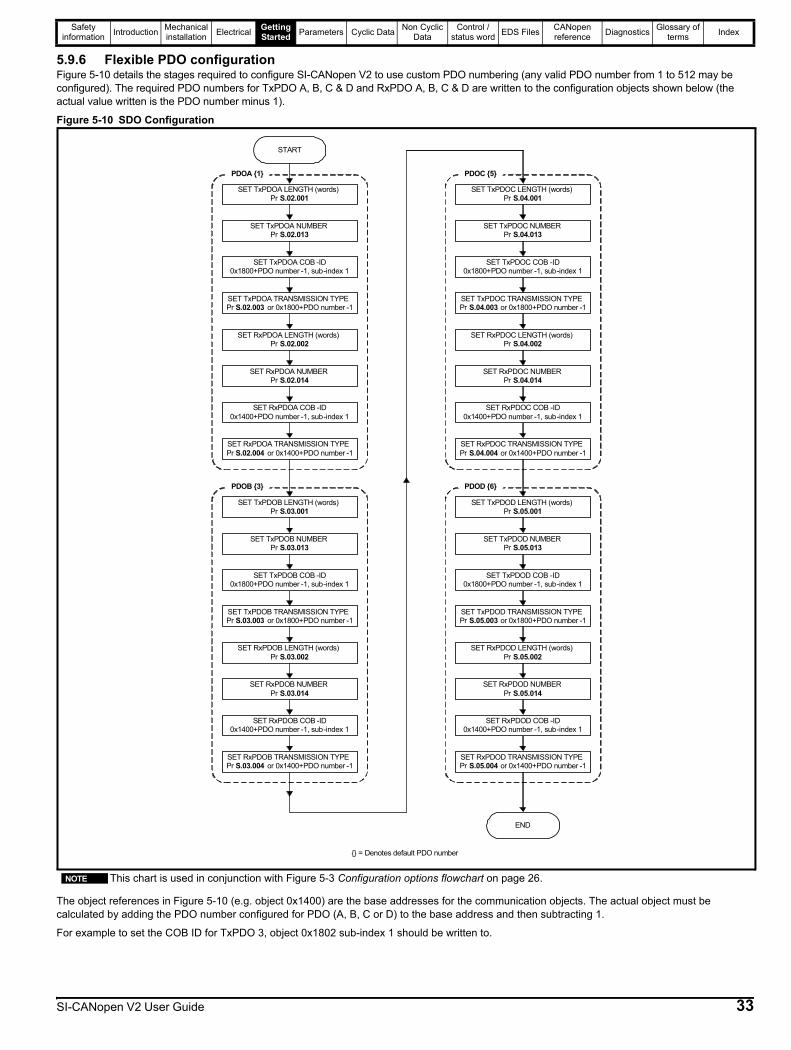
Safety information Introduction Mechanical
installation Electrical Getting Started Parameters Cyclic Data Non Cyclic
DataControl /
status word EDS Files CANopen reference Diagnostics Glossary of
terms Index
5.9.6 Flexible PDO configurationFigure 5-10 details the stages required to configure SI-CANopen V2 to use custom PDO numbering (any valid PDO number from 1 to 512 may be configured). The required PDO numbers for TxPDO A, B, C & D and RxPDO A, B, C & D are written to the configuration objects shown below (the actual value written is the PDO number minus 1).
Figure 5-10 SDO Configuration
The object references in Figure 5-10 (e.g. object 0x1400) are the base addresses for the communication objects. The actual object must be calculated by adding the PDO number configured for PDO (A, B, C or D) to the base address and then subtracting 1.
For example to set the COB ID for TxPDO 3, object 0x1802 sub-index 1 should be written to.
This chart is used in conjunction with Figure 5-3 Configuration options flowchart on page 26.
START
END
SET TxPDOA LENGTH (words)Pr S.02.001
SET TxPDOA TRANSMISSION TYPEPr S.02.003 or 0x1800+PDO number -1
SET TxPDOA NUMBERPr S.02.013
SET TxPDOA COB -ID0x1800+PDO number -1, sub-index 1
SET RxPDOA LENGTH (words)Pr S.02.002
SET RxPDOA TRANSMISSION TYPEPr S.02.004 or 0x1400+PDO number -1
SET RxPDOA NUMBERPr S.02.014
SET RxPDOA COB -ID0x1400+PDO number -1, sub-index 1
PDOA {1}
SET TxPDOB LENGTH (words)Pr S.03.001
SET TxPDOB TRANSMISSION TYPEPr S.03.003 or 0x1800+PDO number -1
SET TxPDOB NUMBERPr S.03.013
SET TxPDOB COB -ID0x1800+PDO number -1, sub-index 1
SET RxPDOB LENGTH (words)Pr S.03.002
SET RxPDOB TRANSMISSION TYPEPr S.03.004 or 0x1400+PDO number -1
SET RxPDOB NUMBERPr S.03.014
SET RxPDOB COB -ID0x1400+PDO number -1, sub-index 1
PDOB {3}
SET TxPDOC LENGTH (words)Pr S.04.001
SET TxPDOC TRANSMISSION TYPEPr S.04.003 or 0x1800+PDO number -1
SET TxPDOC NUMBERPr S.04.013
SET TxPDOC COB -ID0x1800+PDO number -1, sub-index 1
SET RxPDOC LENGTH (words)Pr S.04.002
SET RxPDOC TRANSMISSION TYPEPr S.04.004 or 0x1400+PDO number -1
SET RxPDOC NUMBERPr S.04.014
SET RxPDOC COB -ID0x1400+PDO number -1, sub-index 1
PDOC {5}
SET TxPDOD LENGTH (words)Pr S.05.001
SET TxPDOD TRANSMISSION TYPEPr S.05.003 or 0x1800+PDO number -1
SET TxPDOD NUMBERPr S.05.013
SET TxPDOD COB -ID0x1800+PDO number -1, sub-index 1
SET RxPDOD LENGTH (words)Pr S.05.002
SET RxPDOD TRANSMISSION TYPEPr S.05.004 or 0x1400+PDO number -1
SET RxPDOD NUMBERPr S.05.014
SET RxPDOD COB -ID0x1400+PDO number -1, sub-index 1
PDOD {6}
{} = Denotes default PDO number
NOTE
SI-CANopen V2 User Guide 33

Safety information Introduction Mechanical
installation Electrical Getting Started Parameters Cyclic Data Non Cyclic
DataControl /
status word EDS Files CANopen reference Diagnostics Glossary of
terms Index
5.9.7 Saving SDO setup in SI-CANopen V2Figure 5-11 details the procedure to save previously sent SDO configuration settings to the SI-CANopen V2 internal memory. This removes the requirement to re-send configuration SDOs if the SI-CANopen V2 is reset or powered down.
Figure 5-11 Saving SDO setup
START
END
OBJECT 0x1010 “WRITE
SAVE COMMAND”
(see section 11.13)
34 SI-CANopen V2 User Guide
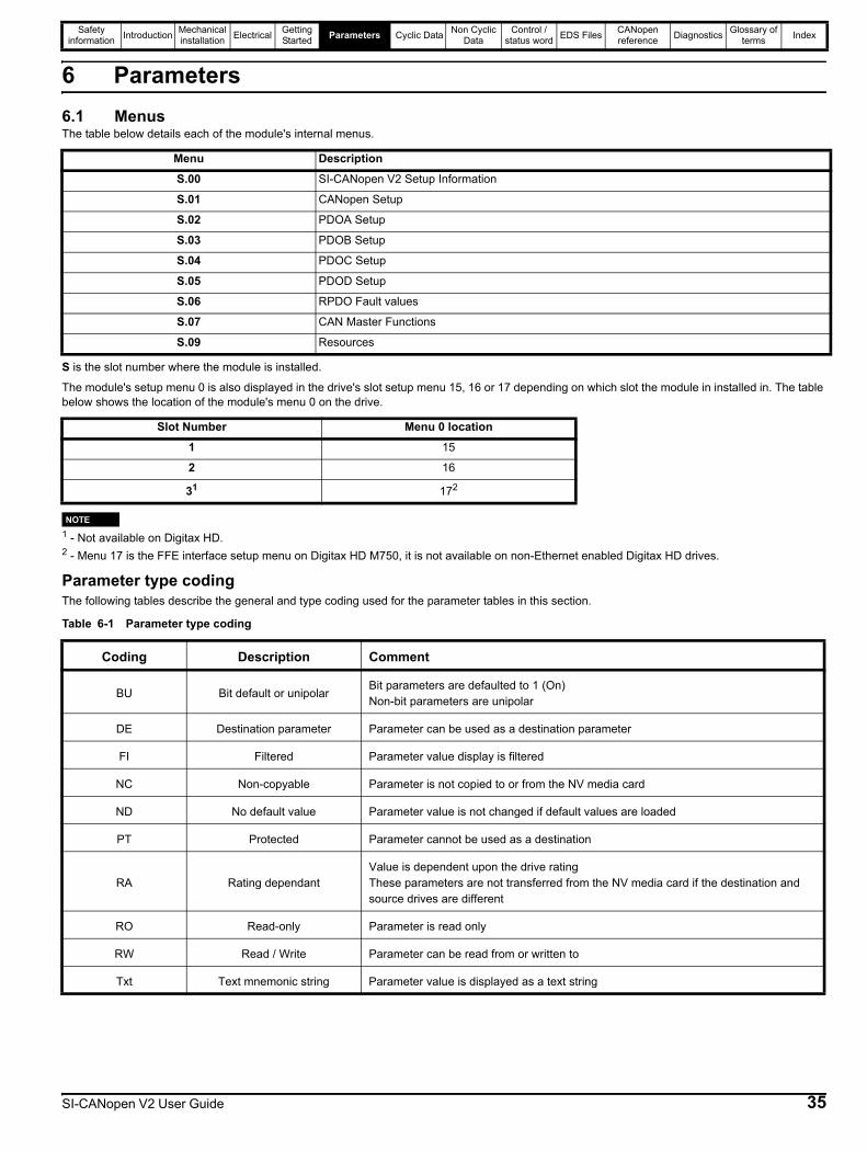
Safety information Introduction Mechanical
installation Electrical Getting Started Parameters Cyclic Data Non Cyclic
DataControl /
status word EDS Files CANopen reference Diagnostics Glossary of
terms Index
6 Parameters6.1 MenusThe table below details each of the module's internal menus.
S is the slot number where the module is installed.
The module's setup menu 0 is also displayed in the drive's slot setup menu 15, 16 or 17 depending on which slot the module in installed in. The table below shows the location of the module's menu 0 on the drive.
1 - Not available on Digitax HD.2 - Menu 17 is the FFE interface setup menu on Digitax HD M750, it is not available on non-Ethernet enabled Digitax HD drives.
Parameter type codingThe following tables describe the general and type coding used for the parameter tables in this section.
Table 6-1 Parameter type coding
Menu DescriptionS.00 SI-CANopen V2 Setup Information
S.01 CANopen Setup
S.02 PDOA Setup
S.03 PDOB Setup
S.04 PDOC Setup
S.05 PDOD Setup
S.06 RPDO Fault values
S.07 CAN Master Functions
S.09 Resources
Slot Number Menu 0 location1 15
2 16
31 172
NOTE
Coding Description Comment
BU Bit default or unipolarBit parameters are defaulted to 1 (On)Non-bit parameters are unipolar
DE Destination parameter Parameter can be used as a destination parameter
FI Filtered Parameter value display is filtered
NC Non-copyable Parameter is not copied to or from the NV media card
ND No default value Parameter value is not changed if default values are loaded
PT Protected Parameter cannot be used as a destination
RA Rating dependantValue is dependent upon the drive ratingThese parameters are not transferred from the NV media card if the destination and source drives are different
RO Read-only Parameter is read only
RW Read / Write Parameter can be read from or written to
Txt Text mnemonic string Parameter value is displayed as a text string
SI-CANopen V2 User Guide 35
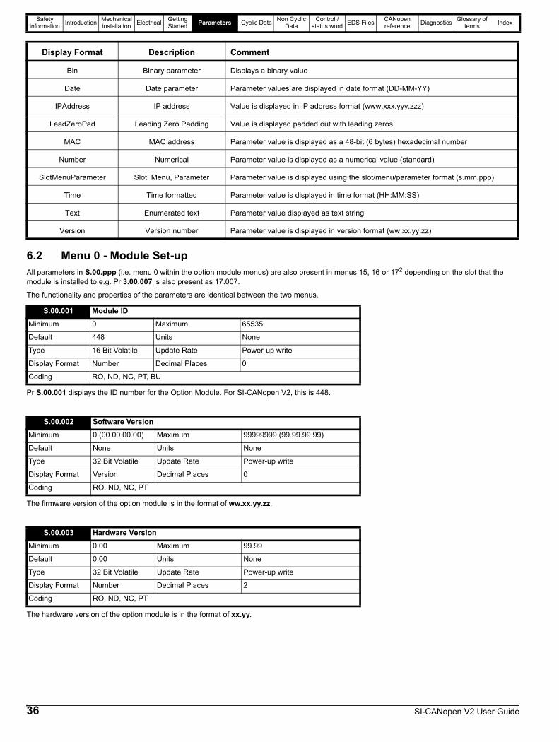
Safety information Introduction Mechanical
installation Electrical Getting Started Parameters Cyclic Data Non Cyclic
DataControl /
status word EDS Files CANopen reference Diagnostics Glossary of
terms Index
6.2 Menu 0 - Module Set-upAll parameters in S.00.ppp (i.e. menu 0 within the option module menus) are also present in menus 15, 16 or 172 depending on the slot that the module is installed to e.g. Pr 3.00.007 is also present as 17.007.
The functionality and properties of the parameters are identical between the two menus.
Pr S.00.001 displays the ID number for the Option Module. For SI-CANopen V2, this is 448.
The firmware version of the option module is in the format of ww.xx.yy.zz.
The hardware version of the option module is in the format of xx.yy.
Display Format Description Comment
Bin Binary parameter Displays a binary value
Date Date parameter Parameter values are displayed in date format (DD-MM-YY)
IPAddress IP address Value is displayed in IP address format (www.xxx.yyy.zzz)
LeadZeroPad Leading Zero Padding Value is displayed padded out with leading zeros
MAC MAC address Parameter value is displayed as a 48-bit (6 bytes) hexadecimal number
Number Numerical Parameter value is displayed as a numerical value (standard)
SlotMenuParameter Slot, Menu, Parameter Parameter value is displayed using the slot/menu/parameter format (s.mm.ppp)
Time Time formatted Parameter value is displayed in time format (HH:MM:SS)
Text Enumerated text Parameter value displayed as text string
Version Version number Parameter value is displayed in version format (ww.xx.yy.zz)
S.00.001 Module IDMinimum 0 Maximum 65535
Default 448 Units None
Type 16 Bit Volatile Update Rate Power-up write
Display Format Number Decimal Places 0
Coding RO, ND, NC, PT, BU
S.00.002 Software VersionMinimum 0 (00.00.00.00) Maximum 99999999 (99.99.99.99)
Default None Units None
Type 32 Bit Volatile Update Rate Power-up write
Display Format Version Decimal Places 0
Coding RO, ND, NC, PT
S.00.003 Hardware VersionMinimum 0.00 Maximum 99.99
Default 0.00 Units None
Type 32 Bit Volatile Update Rate Power-up write
Display Format Number Decimal Places 2
Coding RO, ND, NC, PT
36 SI-CANopen V2 User Guide
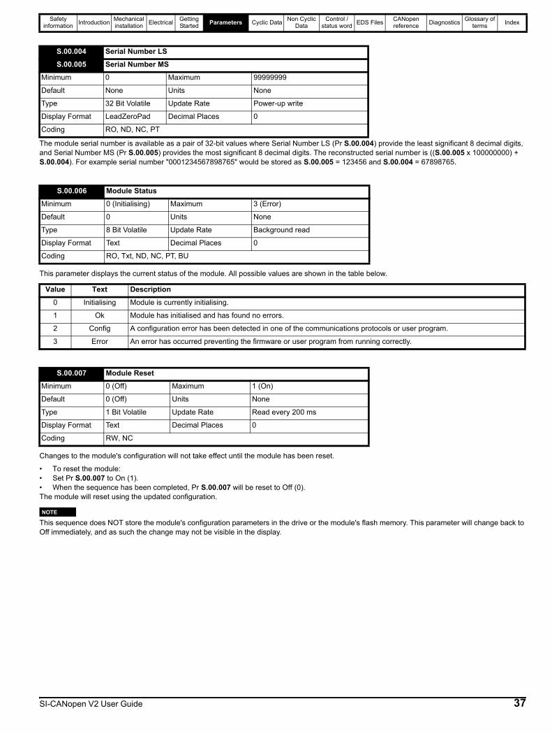
Safety information Introduction Mechanical
installation Electrical Getting Started Parameters Cyclic Data Non Cyclic
DataControl /
status word EDS Files CANopen reference Diagnostics Glossary of
terms Index
The module serial number is available as a pair of 32-bit values where Serial Number LS (Pr S.00.004) provide the least significant 8 decimal digits, and Serial Number MS (Pr S.00.005) provides the most significant 8 decimal digits. The reconstructed serial number is ((S.00.005 x 100000000) + S.00.004). For example serial number "0001234567898765" would be stored as S.00.005 = 123456 and S.00.004 = 67898765.
This parameter displays the current status of the module. All possible values are shown in the table below.
Changes to the module's configuration will not take effect until the module has been reset.
• To reset the module:• Set Pr S.00.007 to On (1).• When the sequence has been completed, Pr S.00.007 will be reset to Off (0).The module will reset using the updated configuration.
This sequence does NOT store the module's configuration parameters in the drive or the module's flash memory. This parameter will change back to Off immediately, and as such the change may not be visible in the display.
S.00.004 Serial Number LSS.00.005 Serial Number MS
Minimum 0 Maximum 99999999
Default None Units None
Type 32 Bit Volatile Update Rate Power-up write
Display Format LeadZeroPad Decimal Places 0
Coding RO, ND, NC, PT
S.00.006 Module StatusMinimum 0 (Initialising) Maximum 3 (Error)
Default 0 Units None
Type 8 Bit Volatile Update Rate Background read
Display Format Text Decimal Places 0
Coding RO, Txt, ND, NC, PT, BU
Value Text Description0 Initialising Module is currently initialising.
1 Ok Module has initialised and has found no errors.
2 Config A configuration error has been detected in one of the communications protocols or user program.
3 Error An error has occurred preventing the firmware or user program from running correctly.
S.00.007 Module ResetMinimum 0 (Off) Maximum 1 (On)
Default 0 (Off) Units None
Type 1 Bit Volatile Update Rate Read every 200 ms
Display Format Text Decimal Places 0
Coding RW, NC
NOTE
SI-CANopen V2 User Guide 37
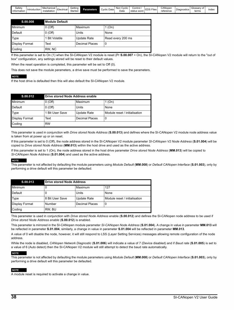
Safety information Introduction Mechanical
installation Electrical Getting Started Parameters Cyclic Data Non Cyclic
DataControl /
status word EDS Files CANopen reference Diagnostics Glossary of
terms Index
If this parameter is set to On (1) when the SI-CANopen V2 module is reset (Pr S.00.007 = On), the SI-CANopen V2 module will return to the "out of box" configuration, any settings stored will be reset to their default values.
When the reset operation is completed, this parameter will be set to Off (0).
This does not save the module parameters, a drive save must be performed to save the parameters.
If the host drive is defaulted then this will also default the SI-CANopen V2 module.
This parameter is used in conjunction with Drive stored Node Address (S.00.013) and defines where the SI-CANopen V2 module node address value is taken from at power up or on reset.If this parameter is set to 0 (Off), the node address stored in the SI-CANopen V2 module parameter SI-CANopen V2 Node Address (S.01.004) will be copied to Drive stored Node Address (MM.013) within the host drive and used as the active address.If this parameter is set to 1 (On), the node address stored in the host drive parameter Drive stored Node Address (MM.013) will be copied to SI-CANopen Node Address (S.01.004) and used as the active address.
This parameter is not affected by defaulting the module parameters using Module Default (MM.008) or Default CANopen Interface (S.01.003), only by performing a drive default will this parameter be defaulted.
This parameter is used in conjunction with Drive stored Node Address enable (S.00.012) and defines the SI-CANopen node address to be used if Drive stored Node Address enable (S.00.012) is enabled.This parameter is mirrored in the SI-CANopen module parameter SI-CANopen Node Address (S.01.004). A change in value in parameter MM.013 will be reflected in parameter S.01.004, similarly, a change in value in parameter S.01.004 will be reflected in parameter MM.013.A value of 0 will disable the node, however, it will still respond to LSS (Layer Setting Services) messages allowing remote configuration of the node address.While the node is disabled, CANopen Network Diagnostic (S.01.006) will indicate a value of 7 (Device disabled) and if Baud rate (S.01.005) is set to a value of 6 (Auto detect) then the SI-CANopen V2 module will still attempt to detect the baud rate automatically.
This parameter is not affected by defaulting the module parameters using Module Default (MM.008) or Default CANopen Interface (S.01.003), only by performing a drive default will this parameter be defaulted.
A module reset is required to activate a change in value.
S.00.008 Module DefaultMinimum 0 (Off) Maximum 1 (On)
Default 0 (Off) Units None
Type 1 Bit Volatile Update Rate Read every 200 ms
Display Format Text Decimal Places 0
Coding RW, NC
S.00.012 Drive stored Node Address enableMinimum 0 (Off) Maximum 1 (On)
Default 0 (Off) Units None
Type 1 Bit User Save Update Rate Module reset / initialisation
Display Format Text Decimal Places 0
Coding RW
S.00.013 Drive stored Node AddressMinimum 0 Maximum 127
Default 0 Units None
Type 8 Bit User Save Update Rate Module reset / initialisation
Display Format Number Decimal Places 0
Coding RW, BU
NOTE
NOTE
NOTE
NOTE
38 SI-CANopen V2 User Guide
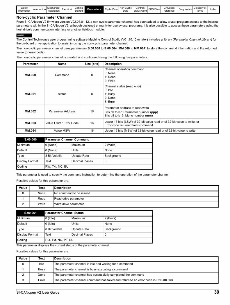
Safety information Introduction Mechanical
installation Electrical Getting Started Parameters Cyclic Data Non Cyclic
DataControl /
status word EDS Files CANopen reference Diagnostics Glossary of
terms Index
Non-cyclic Parameter ChannelFrom SI-CANopen V2 firmware version V02.04.01.12, a non-cyclic parameter channel has been added to allow a user program access to the internal parameters within the SI-CANopen V2, although designed primarily for use by user programs, it is also possible to access these parameters using the host drive’s communication interface or another fieldbus module.
The Control Techniques user programming software Machine Control Studio (V01.10.10 or later) includes a library (Parameter Channel Library) for the on-board drive application to assist in using the non-cyclic parameter channel.The non-cyclic parameter channel uses parameters S.00.060 to S.00.064 (MM.060 to MM.064) to store the command information and the returned value (or error code).The non-cyclic parameter channel is created and configured using the following five parameters:
This parameter is used to specify the command instruction to determine the operation of the parameter channel.
Possible values for this parameter are:
This parameter displays the current status of the parameter channel.
Possible values for this parameter are:
Parameter Name Size (bits) Description
MM.060 Command 8
Channel operation command0: None1: Read2: Write
MM.061 Status 8
Channel status (read only)0: Idle1: Busy2: Done3: Error
MM.062 Parameter Address 16Parameter address to read/writeBits b0 to b7: Parameter number (ppp)Bits b8 to b15: Menu number (mm)
MM.063 Value LSW / Error Code 16 Lower 16 bits (LSW) of 32-bit value read or of 32-bit value to write, orError code returned from command
MM.064 Value MSW 16 Upper 16 bits (MSW) of 32-bit value read or of 32-bit value to write
NOTE
S.00.060 Parameter Channel CommandMinimum 0 (None) Maximum 2 (Write)
Default 0 (None) Units None
Type 8 Bit Volatile Update Rate Background
Display Format Text Decimal Places 0
Coding RW, Txt, NC, BU
Value Text Description0 None No command to be issued
1 Read Read drive parameter
2 Write Write drive parameter
S.00.061 Parameter Channel StatusMinimum 0 (Idle) Maximum 2 (Error)
Default 0 (Idle) Units None
Type 8 Bit Volatile Update Rate Background
Display Format Text Decimal Places 0
Coding RO, Txt, NC, PT, BU
Value Text Description0 Idle The parameter channel is idle and waiting for a command
1 Busy The parameter channel is busy executing a command
2 Done The parameter channel has successfully completed the command
3 Error The parameter channel command has failed and returned an error code in Pr S.00.063
SI-CANopen V2 User Guide 39

Safety information Introduction Mechanical
installation Electrical Getting Started Parameters Cyclic Data Non Cyclic
DataControl /
status word EDS Files CANopen reference Diagnostics Glossary of
terms Index
This parameter specifies the parameter address to read from, or write to.The format of this parameter is equivalent to mm.ppp, where the most significant 8 bits represent the menu number and the least significant 8 bits represent the parameter number within that menu.This means that the maximum number possible for both the menu and parameter is 255.i.e. mm.ppp = 255.255.The value entered in this parameter is calculated using the formula:
S.00.062 = mm * 256 + pppExample:To reset the CANopen interface (Pr 01.002), the decimal value of 258 (0b0000 0001 0000 0010) should be entered.Please note that a slot number cannot be entered as the parameter channel only provides access to its own module parameters and NOT the host drive's parameters.
The data in this parameter depends on what command instruction is used and the channel status as shown in the following table:
Possible error codes are:
S.00.062 Parameter Channel Parameter AccessMinimum 0 Maximum 65535
Default 0 Units None
Type 16 Bit Volatile Update Rate Background
Display Format Number Decimal Places 0
Coding RW, NC, BU
S.00.063 Parameter Channel Value LSW / Error CodeMinimum -32768 Maximum 32767
Default 0 Units None
Type 16 Bit Volatile Update Rate On operation
Display Format Number Decimal Places 0
Coding RW, NC
Command Parameter Data
ReadStatus (MM.061) = 2: Least significant word of value read from the parameter address set in Pr MM.062Status (MM.061) = 3: Error code value
WriteStatus (MM.061) = 2: Least significant word of value to write to the parameter address set in Pr MM.062Status (MM.061) = 3: Error code value
Value Meaning Description-1 Reserved Reserved error code
-2 Reserved Reserved error code
-3 Reserved Reserved error code
-4 Does not exist The specified parameter does not exist
-5 Data Type The data could not be converted from the specified type
-6 Reserved The data could not be read (reason unknown)
-7 Reserved The data could not be written (reason unknown)
-8 Not Readable The data could not be read as the source does not allow read access
-9 Not Writeable The data could not be written as the destination does not allow write access
-10 Over Range The specified value is outside the range of the specified parameter
-11 Reserved Reserved error code
-12 Reserved Reserved error code
-13 Decimal Place The decimal place information is invalid (outside the allowed writeable range for the specified parameter)
-14 Reserved Reserved error code
-15 Invalid CMD The command is invalid
40 SI-CANopen V2 User Guide

Safety information Introduction Mechanical
installation Electrical Getting Started Parameters Cyclic Data Non Cyclic
DataControl /
status word EDS Files CANopen reference Diagnostics Glossary of
terms Index
The data in this parameter depends on what command instruction is used as shown in the following table:
Using the non-cyclic parameter channelFigure 6-1 shows the sequence for reading a parameter and Figure 6-2 shows the sequence for a write command.
For both read and write operations, the Read or Write command (MM.061) must be written last, after all other parameters have been written.
Value Meaning Description-16 Reserved Reserved error code
-17 Unknown Error An unknown error has been detected
-18 64-bit access Unsupported read/write access to a 64-bit parameter
-19 to -128 Reserved Reserved error code
S.00.064 Parameter Channel Value MSWMinimum -32768 Maximum 32767
Default 0 Units None
Type 16 Bit Volatile Update Rate On operation
Display Format Number Decimal Places 0
Coding RW, NC
Command Parameter DataRead Most significant word of value read from the parameter address set in Pr MM.062Write Most significant word of value to write to the parameter address set in Pr MM.062
NOTE
SI-CANopen V2 User Guide 41

Safety information Introduction Mechanical
installation Electrical Getting Started Parameters Cyclic Data Non Cyclic
DataControl /
status word EDS Files CANopen reference Diagnostics Glossary of
terms Index
Figure 6-1 Non-cyclic parameter channel read access
START
Read Channel Status (MM.061)
Set Command to “None”(MM.060 = 0)
Not BusyBusy
Set Parameter Address(MM.062)
Set Command to “Read”(MM.060 = 1)
Check Channel Status
Idle /Busy Error
Read unsuccessful.MM.063 contains Error Code
Diagnose error, make necessary changes
Set Command to “None”(MM.060 = 0)
Done
Read successful.MM.063 contains LSW valueMM.064 contains MSW value
Set Command to “None”(MM.060 = 0)
Check Channel Status
Check Channel Status
BusyNot Busy
Read Channel Status (MM.061)
Read Channel Status (MM.061)
End
42 SI-CANopen V2 User Guide

Safety information Introduction Mechanical
installation Electrical Getting Started Parameters Cyclic Data Non Cyclic
DataControl /
status word EDS Files CANopen reference Diagnostics Glossary of
terms Index
Figure 6-2 Non-cyclic parameter channel write access
START
Read Channel Status (MM.061)
Set Command to “None”(MM.060 = 0)
Not BusyBusy
Set Parameter Address(MM.062)
Set Command to “Write”(MM.060 = 2)
Check Channel Status
Idle / Busy Error
Write unsuccessful.MM.063 contains Error Code
Diagnose error, make necessary changes
Set Command to “None”(MM.060 = 0)
Done
Write successful.
Set Command to “None”(MM.060 = 0)
Check Channel Status
Check Channel Status
BusyNot Busy
Read Channel Status (MM.061)
Read Channel Status (MM.061)
End
Split the value to write into two 16-bit values
Write the LSW into MM.063
Write the MSW into MM.064
SI-CANopen V2 User Guide 43

Safety information Introduction Mechanical
installation Electrical Getting Started Parameters Cyclic Data Non Cyclic
DataControl /
status word EDS Files CANopen reference Diagnostics Glossary of
terms Index
Non-cyclic Parameter Channel Worked Example
This example demonstrates using the non-cyclic parameter channel to read the SI-CANopen V2 module CANopen Network Diagnostic (Pr S.01.006) and write the value 408 to the CANopen Identification Override (Pr S.01.030).
The entire program is written in the Freewheeling task POU.
Please note that this example is provided for reference purposes only, it is not intended to be used directly in a user program. It is the user's responsibility to ensure any user program code provided in the example is used correctly and satisfies the application requirements.Figure 6-3 Freewheeling Task Variables Declaration
44 SI-CANopen V2 User Guide
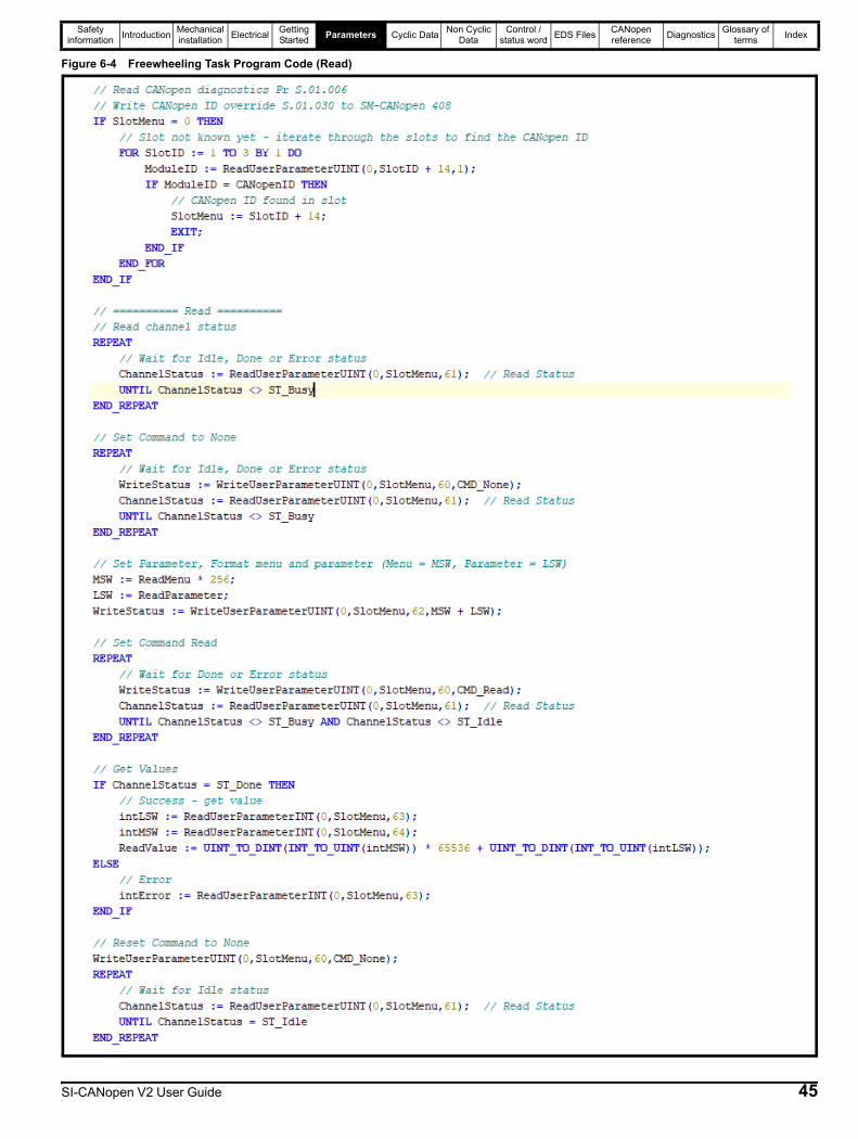
Safety information Introduction Mechanical
installation Electrical Getting Started Parameters Cyclic Data Non Cyclic
DataControl /
status word EDS Files CANopen reference Diagnostics Glossary of
terms Index
Figure 6-4 Freewheeling Task Program Code (Read)
SI-CANopen V2 User Guide 45

Safety information Introduction Mechanical
installation Electrical Getting Started Parameters Cyclic Data Non Cyclic
DataControl /
status word EDS Files CANopen reference Diagnostics Glossary of
terms Index
Figure 6-5 Freewheeling Task Program Code (Write)
46 SI-CANopen V2 User Guide

Safety information Introduction Mechanical
installation Electrical Getting Started Parameters Cyclic Data Non Cyclic
DataControl /
status word EDS Files CANopen reference Diagnostics Glossary of
terms Index
6.3 Menu 1 - CANopen SetupMenu 1 contains all the parameters relating to the setup of the CANopen interface on the SI-CANopen V2 module.
As of SI-CANopen V2 firmware V02.01.00.26 the functionality of this parameter has changed, previously this parameter only enabled or disabled the CANopen interface. The maximum value has been increased to 2 and the data type changed to 8 bit User Save.
This parameter now determines the SI-CANopen V2 module startup behaviour, by default the SI-CANopen V2 will send the BOOTUP message at startup or after a reset, if no other active node is on the network to acknowledge the BOOTUP message, SI-CANopen V2 will enter the BUS Passive state. Setting this parameter to the value 2 will enable the CANopen interface but the BOOTUP message at startup will not be sent.
The possible values are shown in the following table.
Setting Pr S.01.001 to a value of 0 will disable CANopen functionality and allow the SI-CANopen V2 module function in a similar manner to that of the SM-CAN option module.
User (raw) CAN LevelAs of firmware V02.01.00.26 the SI-CANopen V2 module supports the user (raw) CAN functionality, this allows users to use CAN level communication messages with an SI-Applications Plus (or SI-Applications Compact) or MCi2xx using the programming software SyPT Pro or Machine Control Studio respectively.
For more information on the CAN functionality please refer to the online help in the appropriate programming software.
It is possible to have both CANopen level and user CAN level functionality enabled simultaneously. In this case users must consider any implications this may cause.
SI-CANopen V2 does not support the AssociatedIntOpComms function when used with the MCi2x0 option module.
This parameter is the same as Pr MM.007 Module Reset, on a transition from 0 (Off) to 1 (On), the SI-CANopen V2 module will reset the value to 0 (Off) and write 1 (On) to Pr MM.007.
Changes to the module's configuration will not take effect until the module has been reset.
To reset the module:
• Set Pr S.01.002 to On (1).• When the sequence has been completed, Pr S.01.002 will be reset to Off (0).• The module will reset using the updated configuration.
This sequence does NOT store the module's configuration parameters in the drive or the module's flash memory. This parameter will change back to Off immediately, and as such the change may not be visible in the display.
S.01.001 CANopen Interface ModeMinimum 0 (Off) Maximum 2 (On No Bootup)
Default 1 (On) Units None
Type 8 Bit User Save Update Rate Module reset / initialisation
Display Format Text Decimal Places 0
Coding RW, Txt
Value Text Description
0 OffCANopen functionality is disabled.CAN bus is enabled and available for use with user CAN functionality provided by SI-Applications (Plus/Compact) or MCi2xx.
1 OnCANopen functionality is enabled.CAN bus shared between CANopen slave functionality and user CAN functionality provided by SI-Applications (Plus/Compact) or MCi2xx.
2 On No BootupCANopen functionality is enabled.The SI-CANopen V2 module will not send CANopen BOOTUP message at startup, this is to avoid the CAN bus entering the PASSIVE state if this is the first CAN node to power up on the CAN bus.
S.01.002 Reset CANopen InterfaceMinimum 0 (Off) Maximum 1 (On)
Default 0 (Off) Units None
Type 1 Bit Volatile Update Rate Read every 200 ms
Display Format Text Decimal Places 0
Coding RW
NOTE
NOTE
NOTE
SI-CANopen V2 User Guide 47
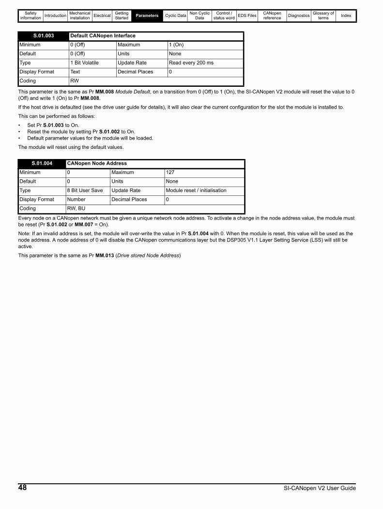
Safety information Introduction Mechanical
installation Electrical Getting Started Parameters Cyclic Data Non Cyclic
DataControl /
status word EDS Files CANopen reference Diagnostics Glossary of
terms Index
This parameter is the same as Pr MM.008 Module Default, on a transition from 0 (Off) to 1 (On), the SI-CANopen V2 module will reset the value to 0 (Off) and write 1 (On) to Pr MM.008.
If the host drive is defaulted (see the drive user guide for details), it will also clear the current configuration for the slot the module is installed to.
This can be performed as follows:
• Set Pr S.01.003 to On.• Reset the module by setting Pr S.01.002 to On.• Default parameter values for the module will be loaded.
The module will reset using the default values.
Every node on a CANopen network must be given a unique network node address. To activate a change in the node address value, the module must be reset (Pr S.01.002 or MM.007 = On).
Note: If an invalid address is set, the module will over-write the value in Pr S.01.004 with 0. When the module is reset, this value will be used as the node address. A node address of 0 will disable the CANopen communications layer but the DSP305 V1.1 Layer Setting Service (LSS) will still be active.
This parameter is the same as Pr MM.013 (Drive stored Node Address)
S.01.003 Default CANopen InterfaceMinimum 0 (Off) Maximum 1 (On)
Default 0 (Off) Units None
Type 1 Bit Volatile Update Rate Read every 200 ms
Display Format Text Decimal Places 0
Coding RW
S.01.004 CANopen Node AddressMinimum 0 Maximum 127
Default 0 Units None
Type 8 Bit User Save Update Rate Module reset / initialisation
Display Format Number Decimal Places 0
Coding RW, BU
48 SI-CANopen V2 User Guide
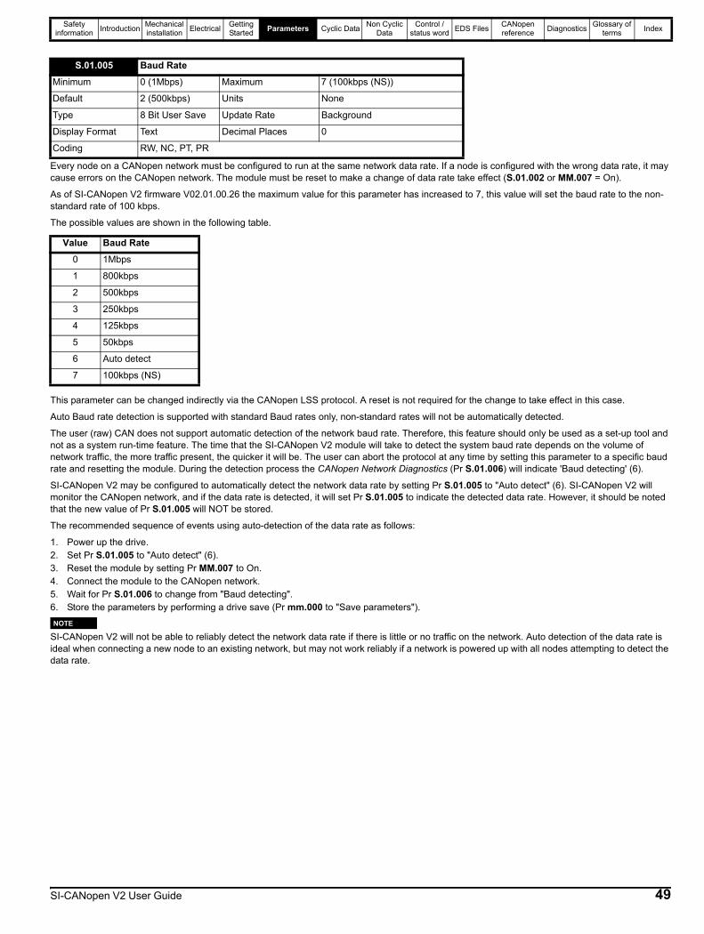
Safety information Introduction Mechanical
installation Electrical Getting Started Parameters Cyclic Data Non Cyclic
DataControl /
status word EDS Files CANopen reference Diagnostics Glossary of
terms Index
Every node on a CANopen network must be configured to run at the same network data rate. If a node is configured with the wrong data rate, it may cause errors on the CANopen network. The module must be reset to make a change of data rate take effect (S.01.002 or MM.007 = On).
As of SI-CANopen V2 firmware V02.01.00.26 the maximum value for this parameter has increased to 7, this value will set the baud rate to the non-standard rate of 100 kbps.
The possible values are shown in the following table.
This parameter can be changed indirectly via the CANopen LSS protocol. A reset is not required for the change to take effect in this case.
Auto Baud rate detection is supported with standard Baud rates only, non-standard rates will not be automatically detected.
The user (raw) CAN does not support automatic detection of the network baud rate. Therefore, this feature should only be used as a set-up tool and not as a system run-time feature. The time that the SI-CANopen V2 module will take to detect the system baud rate depends on the volume of network traffic, the more traffic present, the quicker it will be. The user can abort the protocol at any time by setting this parameter to a specific baud rate and resetting the module. During the detection process the CANopen Network Diagnostics (Pr S.01.006) will indicate 'Baud detecting' (6).
SI-CANopen V2 may be configured to automatically detect the network data rate by setting Pr S.01.005 to "Auto detect" (6). SI-CANopen V2 will monitor the CANopen network, and if the data rate is detected, it will set Pr S.01.005 to indicate the detected data rate. However, it should be noted that the new value of Pr S.01.005 will NOT be stored.
The recommended sequence of events using auto-detection of the data rate as follows:
1. Power up the drive.2. Set Pr S.01.005 to "Auto detect" (6).3. Reset the module by setting Pr MM.007 to On.4. Connect the module to the CANopen network.5. Wait for Pr S.01.006 to change from "Baud detecting".6. Store the parameters by performing a drive save (Pr mm.000 to "Save parameters").
SI-CANopen V2 will not be able to reliably detect the network data rate if there is little or no traffic on the network. Auto detection of the data rate is ideal when connecting a new node to an existing network, but may not work reliably if a network is powered up with all nodes attempting to detect the data rate.
S.01.005 Baud RateMinimum 0 (1Mbps) Maximum 7 (100kbps (NS))
Default 2 (500kbps) Units None
Type 8 Bit User Save Update Rate Background
Display Format Text Decimal Places 0
Coding RW, NC, PT, PR
Value Baud Rate0 1Mbps
1 800kbps
2 500kbps
3 250kbps
4 125kbps
5 50kbps
6 Auto detect
7 100kbps (NS)
NOTE
SI-CANopen V2 User Guide 49
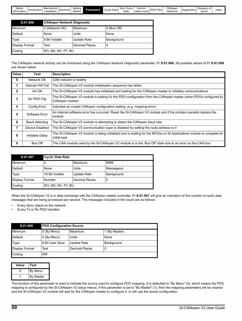
Safety information Introduction Mechanical
installation Electrical Getting Started Parameters Cyclic Data Non Cyclic
DataControl /
status word EDS Files CANopen reference Diagnostics Glossary of
terms Index
The CANopen network activity can be monitored using the CANopen Network Diagnostic parameter, Pr S.01.006. All possible values of Pr S.01.006 are shown below.
When the SI-CANopen V2 is in data exchange with the CANopen master controller, Pr S.01.007 will give an indication of the number of cyclic data messages that are being processed per second. The messages included in the count are as follows:
• Every Sync object on the network.• Every Tx or Rx PDO handled.
The function of this parameter is used to indicate the source used to configure PDO mapping. It is defaulted to "By Menu" (0), which means the PDO mapping is configured by the SI-CANopen V2 setup menus. If this parameter is set to "By Master" (1), then the mapping parameters will be cleared and the SI-CANopen V2 module will wait for the CANopen master to configure it, or will use the saved configuration.
S.01.006 CANopen Network DiagnosticMinimum 0 (Network OK) Maximum 9 (Bus Off)
Default None Units None
Type 8 Bit Volatile Update Rate Background
Display Format Text Decimal Places 0
Coding RO, ND, NC, PT, BU
Value Text Description0 Network OK CAN network is healthy
1 Internal HW Fail The SI-CANopen V2 module initialisation sequence has failed
2 Init OK The SI-CANopen V2 module has initialised and waiting for the CANopen master to initialise communications
3 No PDO Cfg The SI-CANopen V2 module is waiting for the PDO configuration from the CANopen master (when PDOs configured by CANopen master)
4 Config Error Indicates an invalid CANopen configuration setting. (e.g. mapping error)
5 Software Error An internal software error has occurred. Reset the SI-CANopen V2 module and if the problem persists replace the module
6 Baud detecting The SI-CANopen V2 module is attempting to detect the CANopen baud rate
7 Device Disabled The SI-CANopen V2 communication layer is disabled by setting the node address to 0
8 Initialise Delay The SI-CANopen V2 module is being initialised and is waiting for the MCi2xx or SI-Applications module to complete its Initial task
9 Bus Off The CAN module used by the SI-CANopen V2 module is in the ‘Bus Off’ state due to an error on the CAN bus
S.01.007 Cyclic Data RateMinimum 0 Maximum 9999
Default None Units Messages/s
Type 16 Bit Volatile Update Rate Background
Display Format Number Decimal Places 0
Coding RO, ND, NC, PT, BU
S.01.008 PDO Configuration SourceMinimum 0 (By Menu) Maximum 1 (By Master)
Default 0 (By Menu) Units None
Type 8 Bit User Save Update Rate Background
Display Format Text Decimal Places 0
Coding RW
Value Text0 By Menu
1 By Master
50 SI-CANopen V2 User Guide

Safety information Introduction Mechanical
installation Electrical Getting Started Parameters Cyclic Data Non Cyclic
DataControl /
status word EDS Files CANopen reference Diagnostics Glossary of
terms Index
The module will reset an internal timer when a valid message (SYNC or RPDO message) is received from the CANopen network. The network loss trip is triggered when no new messages are received before the timer reaches the designated value.
Pr S.01.011 is used to determine the action to take when a CANopen timeout error occurs.
This parameter deines the destination to trigger the event specified by Pr S.01.011 (Timeout Action) when a timeout event occurs.
S.01.010 Timeout DelayMinimum 0 Maximum 3000
Default 0 Units ms
Type 16 Bit User Save Update Rate Module reset / initialisation
Display Format Number Decimal Places 0
Coding RW, BU
S.01.011 Timeout ActionMinimum 0 (Trip) Maximum 4 (No action)
Default 0 (Trip) Units None
Type 8 Bit User Save Update Rate Module reset / initialisation
Display Format Text Decimal Places 0
Coding RW, TE, BU
Value Text Description0 Trip Trip the drive.
1 Send flt values Send fault values to PLC output parameters.
2 Clear output Set all PLC output parameters to zero.
3 Hold last Hold the last values in the PLC output parameters.
4 No action No action with PLC output parameters.
S.01.012 Timeout Event DestinationMinimum 0 (This slot) Maximum 4 (Slot 4)
Default 0 (This slot) Units None
Type 8 Bit User Save Update Rate Module reset / initialisation
Display Format Text Decimal Places 0
Coding RW, BU
Value Text Description0 This slot This slot
1 Slot 1 Slot 1
2 Slot 2 Slot 2
3 Slot 3 Slot 3
4 Slot 4 Slot 4
S.01.013 Timeout Event TypeMinimum 0 (No event) Maximum 5 (Event4)
Default 0 (No event) Units None
Type 8 Bit User Save Update Rate Module reset / initialisation
Display Format Text Decimal Places 0
Coding RW, BU
SI-CANopen V2 User Guide 51
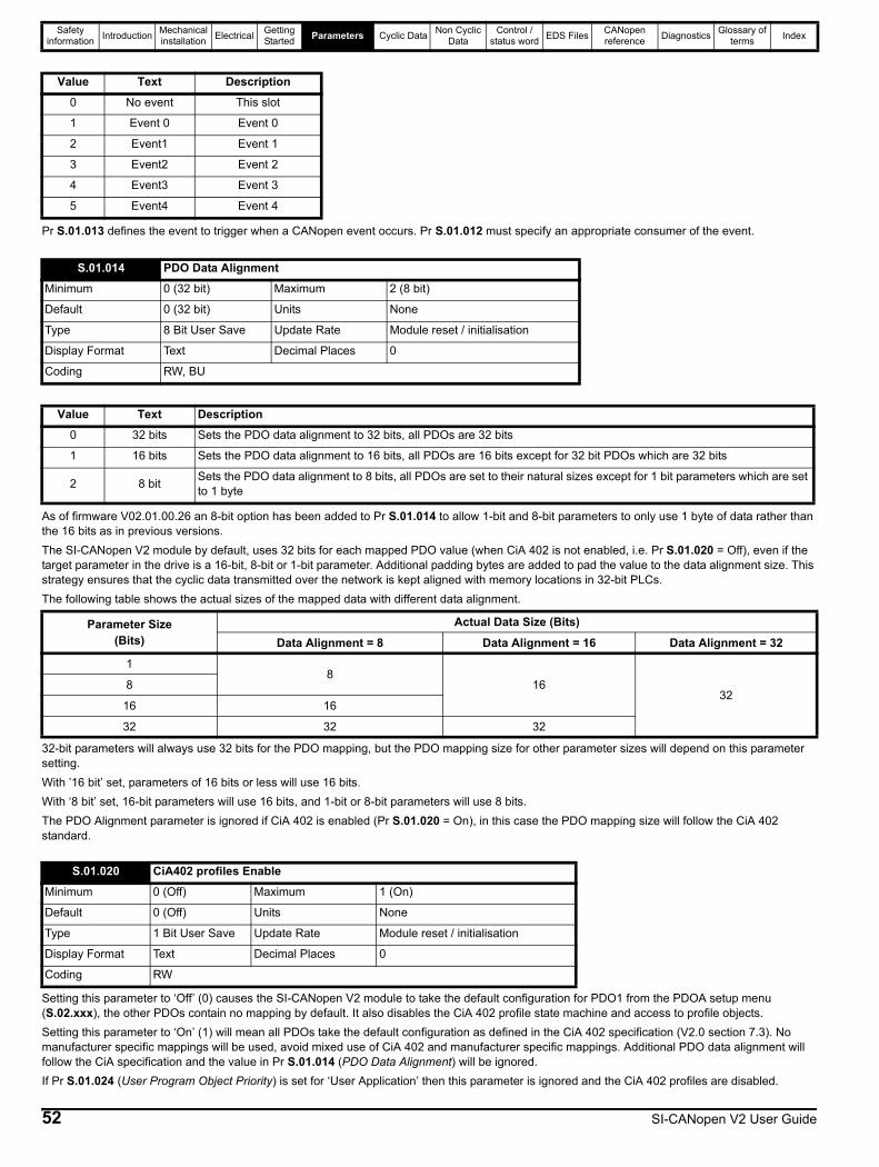
Safety information Introduction Mechanical
installation Electrical Getting Started Parameters Cyclic Data Non Cyclic
DataControl /
status word EDS Files CANopen reference Diagnostics Glossary of
terms Index
Pr S.01.013 defines the event to trigger when a CANopen event occurs. Pr S.01.012 must specify an appropriate consumer of the event.
As of firmware V02.01.00.26 an 8-bit option has been added to Pr S.01.014 to allow 1-bit and 8-bit parameters to only use 1 byte of data rather than the 16 bits as in previous versions.The SI-CANopen V2 module by default, uses 32 bits for each mapped PDO value (when CiA 402 is not enabled, i.e. Pr S.01.020 = Off), even if the target parameter in the drive is a 16-bit, 8-bit or 1-bit parameter. Additional padding bytes are added to pad the value to the data alignment size. This strategy ensures that the cyclic data transmitted over the network is kept aligned with memory locations in 32-bit PLCs.The following table shows the actual sizes of the mapped data with different data alignment.
32-bit parameters will always use 32 bits for the PDO mapping, but the PDO mapping size for other parameter sizes will depend on this parameter setting.With ’16 bit’ set, parameters of 16 bits or less will use 16 bits.With ‘8 bit’ set, 16-bit parameters will use 16 bits, and 1-bit or 8-bit parameters will use 8 bits.The PDO Alignment parameter is ignored if CiA 402 is enabled (Pr S.01.020 = On), in this case the PDO mapping size will follow the CiA 402 standard.
Setting this parameter to ‘Off’ (0) causes the SI-CANopen V2 module to take the default configuration for PDO1 from the PDOA setup menu (S.02.xxx), the other PDOs contain no mapping by default. It also disables the CiA 402 profile state machine and access to profile objects. Setting this parameter to ‘On’ (1) will mean all PDOs take the default configuration as defined in the CiA 402 specification (V2.0 section 7.3). No manufacturer specific mappings will be used, avoid mixed use of CiA 402 and manufacturer specific mappings. Additional PDO data alignment will follow the CiA specification and the value in Pr S.01.014 (PDO Data Alignment) will be ignored.If Pr S.01.024 (User Program Object Priority) is set for ‘User Application’ then this parameter is ignored and the CiA 402 profiles are disabled.
Value Text Description0 No event This slot
1 Event 0 Event 0
2 Event1 Event 1
3 Event2 Event 2
4 Event3 Event 3
5 Event4 Event 4
S.01.014 PDO Data AlignmentMinimum 0 (32 bit) Maximum 2 (8 bit)
Default 0 (32 bit) Units None
Type 8 Bit User Save Update Rate Module reset / initialisation
Display Format Text Decimal Places 0
Coding RW, BU
Value Text Description0 32 bits Sets the PDO data alignment to 32 bits, all PDOs are 32 bits
1 16 bits Sets the PDO data alignment to 16 bits, all PDOs are 16 bits except for 32 bit PDOs which are 32 bits
2 8 bit Sets the PDO data alignment to 8 bits, all PDOs are set to their natural sizes except for 1 bit parameters which are set to 1 byte
Parameter Size(Bits)
Actual Data Size (Bits)Data Alignment = 8 Data Alignment = 16 Data Alignment = 32
18
1632
8
16 16
32 32 32
S.01.020 CiA402 profiles EnableMinimum 0 (Off) Maximum 1 (On)
Default 0 (Off) Units None
Type 1 Bit User Save Update Rate Module reset / initialisation
Display Format Text Decimal Places 0
Coding RW
52 SI-CANopen V2 User Guide
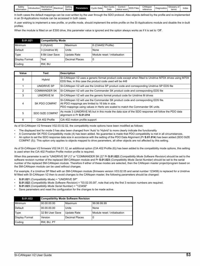
Safety information Introduction Mechanical
installation Electrical Getting Started Parameters Cyclic Data Non Cyclic
DataControl /
status word EDS Files CANopen reference Diagnostics Glossary of
terms Index
In both cases the default mappings can be over-written by the user through the SDO protocol. Also objects defined by the profile and re-implemented in an SI-Applications module can be accessed in both cases.A user wishing to implement a new profile, or profile mode, should implement the entire profile on the SI-Applications module and disable the in-built profiles.When the module is fitted on an E300 drive, this parameter value is ignored and the option always works as if it is set to ‘Off’.
As of SI-CANopen V2 firmware V02.03.02.02, the compatibility mode options have been modified as follows:
• The displayed text for mode 0 has also been changed from 'Auto' to 'Hybrid' to more clearly indicate the functionality• A Commander SK PDO Compatibility mode (4) has been added. No guarantee is made that PDO compatibility is met in all circumstances.• An option to set the SDO response data size in accordance with the setting of the PDO Data Alignment (Pr S.01.014) has been added (SDO SIZE
COMPAT (5)). This option only applies to objects mapped to drive parameters, all other objects are not affected by this setting.
As of SI-CANopen V2 firmware V02.04.01.12, an additional option (CIA 402 Profile (6)) has been added to the compatibility mode options, this setting is used when the CiA 402 Position Profile motion profile is required.
When this parameter is set to "UNIDRIVE SP (1)" or "COMMANDER SK (2)" Pr S.01.022 (Compatibility Mode Software Revision) should be set to the software revision number of the replaced SM-CANopen module and Pr S.01.023 (Compatibility Mode Serial Number) should be set to the serial number of the replaced SM-CANopen module. Therefore if either of these modes are selected, then the CANopen master project/program based on the SM-CANopen module can be used without changes.
For example, if a Unidrive SP fitted with an SM-CANopen module (firmware version V03.02.05 and serial number 123456) is replaced for a Unidrive M fitted with SI-CANopen V2 then to avoid changes to the CANopen master, the following parameters should be changed:
• S.01.021 (Compatibility Mode) = "UNIDRIVE SP"• S.01.022 (Compatibility Mode Software Revision) = "03.02.05.00", note that only the first 3 revision numbers are required.• S.01.023 (Compatibility Mode Serial Number) = "123456"• Save parameters and reset the configuration for the changes to be made active.
S.01.021 Compatibility ModeMinimum 0 (Hybrid) Maximum 6 (CIA402 Profile)
Default 3 (Unidrive M) Units None
Type 8 Bit User Save Update Rate Module reset / initialisation
Display Format Text Decimal Places 0
Coding RW, BU
Value Text Description
0 Hybrid SI-CANopen V2 uses a generic format product code except when fitted to Unidrive M70X drives using M70X EDS files, in this case the product code used will be 448
1 UNIDRIVE SP SI-CANopen V2 will use the Unidrive SP product code and corresponding Unidrive SP EDS file
2 COMMANDER SK SI-CANopen V2 will use the Commander SK product code and corresponding EDS file
3 UNIDRIVE M SI-CANopen V2 will use the generic format product code for Unidrive M drives
4 SK PDO COMPATSI-CANopen V2 will use the Commander SK product code and corresponding EDS file.All PDO mappings are limited to 16 bits in size.PDO mappings using values in Hertz are scaled to match the Commander SK units.
5 SDO SIZE COMPAT As mode 3 (UNIDRIVE M) but in this mode the data size of the SDO response will follow the PDO data alignment in Pr S.01.014
6 CIA 402 Profile CiA 402 motion profile support
S.01.022 Compatibility Mode Software RevisionMinimum 00.00.00.00 Maximum 99.99.99.99
Default 00.00.00.00 Units None
Type 32 Bit User Save Update Rate Module reset / initialisation
Display Format Version Decimal Places 0
Coding RW, BU, PT
SI-CANopen V2 User Guide 53
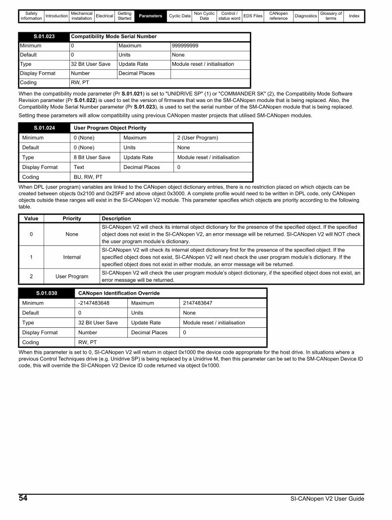
Safety information Introduction Mechanical
installation Electrical Getting Started Parameters Cyclic Data Non Cyclic
DataControl /
status word EDS Files CANopen reference Diagnostics Glossary of
terms Index
When the compatibility mode parameter (Pr S.01.021) is set to "UNIDRIVE SP" (1) or "COMMANDER SK" (2), the Compatibility Mode Software Revision parameter (Pr S.01.022) is used to set the version of firmware that was on the SM-CANopen module that is being replaced. Also, the Compatibility Mode Serial Number parameter (Pr S.01.023), is used to set the serial number of the SM-CANopen module that is being replaced.Setting these parameters will allow compatibility using previous CANopen master projects that utilised SM-CANopen modules.
When DPL (user program) variables are linked to the CANopen object dictionary entries, there is no restriction placed on which objects can be created between objects 0x2100 and 0x25FF and above object 0x3000. A complete profile would need to be written in DPL code, only CANopen objects outside these ranges will exist in the SI-CANopen V2 module. This parameter specifies which objects are priority according to the following table.
When this parameter is set to 0, SI-CANopen V2 will return in object 0x1000 the device code appropriate for the host drive. In situations where a previous Control Techniques drive (e.g. Unidrive SP) is being replaced by a Unidrive M, then this parameter can be set to the SM-CANopen Device ID code, this will override the SI-CANopen V2 Device ID code returned via object 0x1000.
S.01.023 Compatibility Mode Serial NumberMinimum 0 Maximum 999999999
Default 0 Units None
Type 32 Bit User Save Update Rate Module reset / initialisation
Display Format Number Decimal Places
Coding RW, PT
S.01.024 User Program Object Priority
Minimum 0 (None) Maximum 2 (User Program)
Default 0 (None) Units None
Type 8 Bit User Save Update Rate Module reset / initialisation
Display Format Text Decimal Places 0
Coding BU, RW, PT
Value Priority Description
0 NoneSI-CANopen V2 will check its internal object dictionary for the presence of the specified object. If the specified object does not exist in the SI-CANopen V2, an error message will be returned. SI-CANopen V2 will NOT check the user program module’s dictionary.
1 InternalSI-CANopen V2 will check its internal object dictionary first for the presence of the specified object. If the specified object does not exist, SI-CANopen V2 will next check the user program module’s dictionary. If the specified object does not exist in either module, an error message will be returned.
2 User ProgramSI-CANopen V2 will check the user program module’s object dictionary, if the specified object does not exist, an error message will be returned.
S.01.030 CANopen Identification Override
Minimum -2147483648 Maximum 2147483647
Default 0 Units None
Type 32 Bit User Save Update Rate Module reset / initialisation
Display Format Number Decimal Places 0
Coding RW, PT
54 SI-CANopen V2 User Guide

Safety information Introduction Mechanical
installation Electrical Getting Started Parameters Cyclic Data Non Cyclic
DataControl /
status word EDS Files CANopen reference Diagnostics Glossary of
terms Index
6.4 Menu 2 - PDOA SetupMenu 2 contains all the parameters relating the setup of PDOA.
Parameters S.02.001 and S.02.002 define the length (in words) of TPDOA and RPDOA respectively.
The values specified in Pr S.02.001 and S.02.002 will be compared with the actual TPDOA and RPDOA lengths respectively after applying the mappings, if the length is exceeded a Length Mismatch error will be shown in the relevant PDO status parameter.
Any attempt to set a value outside the defined range will cause the module to reset the value to the relevant minimum or maximum value.
Pr S.02.003 sets the current transmission type of TPDOA. Because all PDOs are handled in the same way, if the master changes this setting through the PDO configuration object, the parameter will not be updated.
• Type 0 transmits after a sync message, only when data has changed.• Types 1 to 240 transmit every n sync messages.• (Types 241 to 251 are reserved and will therefore produce an error if selected). See Pr S.02.004).• Type 252 transmits only on remote request, data is updated on receipt of the sync message.• Type 253 data updated and transmits only on remote request.• Type 254 transmits when the TxPDO trigger objects event occurs (0x2850) or in response to an event timer.• Type 255 TxPDO will be transmitted depending on the Profile Specific Mode value in object 0x2832.
The manufacturer specific (254) and profile specific even type (255) will be implemented to transmit the PDO every n ms where n is specified by sub-index 5 of the PDO communication parameter. This value will default to 0, which disables the transmission.
S.02.001 TPDOA LengthS.02.002 RPDOA Length
Minimum 0 Maximum 4
Default 4 Units None
Type 8 Bit Volatile Update Rate Module reset / initialisation
Display Format Number Decimal Places 0
Coding RW, NC
S.02.003 TPDOA Transmission TypeMinimum 0 Maximum 255
Default 255 Units None
Type 8 Bit User Save Update Rate Module reset / initialisation
Display Format Number Decimal Places 0
Coding RW, BU
Transmission type Cyclic Acyclic Synchronous Asynchronous RTR only0 No Yes Yes No No
1 to 240 Yes No Yes No No
241 to 251 Reserved Reserved Reserved Reserved Reserved
252 No No Yes No Yes
253 No No No Yes Yes
254 No No No Yes No
255 No No No Yes No
SI-CANopen V2 User Guide 55
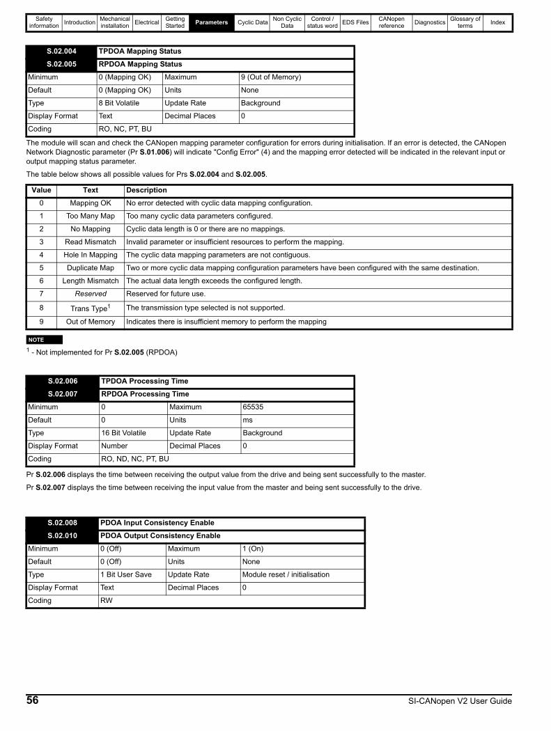
Safety information Introduction Mechanical
installation Electrical Getting Started Parameters Cyclic Data Non Cyclic
DataControl /
status word EDS Files CANopen reference Diagnostics Glossary of
terms Index
The module will scan and check the CANopen mapping parameter configuration for errors during initialisation. If an error is detected, the CANopen Network Diagnostic parameter (Pr S.01.006) will indicate "Config Error" (4) and the mapping error detected will be indicated in the relevant input or output mapping status parameter.
The table below shows all possible values for Prs S.02.004 and S.02.005.
1 - Not implemented for Pr S.02.005 (RPDOA)
Pr S.02.006 displays the time between receiving the output value from the drive and being sent successfully to the master.
Pr S.02.007 displays the time between receiving the input value from the master and being sent successfully to the drive.
S.02.004 TPDOA Mapping StatusS.02.005 RPDOA Mapping Status
Minimum 0 (Mapping OK) Maximum 9 (Out of Memory)
Default 0 (Mapping OK) Units None
Type 8 Bit Volatile Update Rate Background
Display Format Text Decimal Places 0
Coding RO, NC, PT, BU
Value Text Description0 Mapping OK No error detected with cyclic data mapping configuration.
1 Too Many Map Too many cyclic data parameters configured.
2 No Mapping Cyclic data length is 0 or there are no mappings.
3 Read Mismatch Invalid parameter or insufficient resources to perform the mapping.
4 Hole In Mapping The cyclic data mapping parameters are not contiguous.
5 Duplicate Map Two or more cyclic data mapping configuration parameters have been configured with the same destination.
6 Length Mismatch The actual data length exceeds the configured length.
7 Reserved Reserved for future use.
8 Trans Type1 The transmission type selected is not supported.
9 Out of Memory Indicates there is insufficient memory to perform the mapping
S.02.006 TPDOA Processing TimeS.02.007 RPDOA Processing Time
Minimum 0 Maximum 65535
Default 0 Units ms
Type 16 Bit Volatile Update Rate Background
Display Format Number Decimal Places 0
Coding RO, ND, NC, PT, BU
S.02.008 PDOA Input Consistency EnableS.02.010 PDOA Output Consistency Enable
Minimum 0 (Off) Maximum 1 (On)
Default 0 (Off) Units None
Type 1 Bit User Save Update Rate Module reset / initialisation
Display Format Text Decimal Places 0
Coding RW
NOTE
56 SI-CANopen V2 User Guide
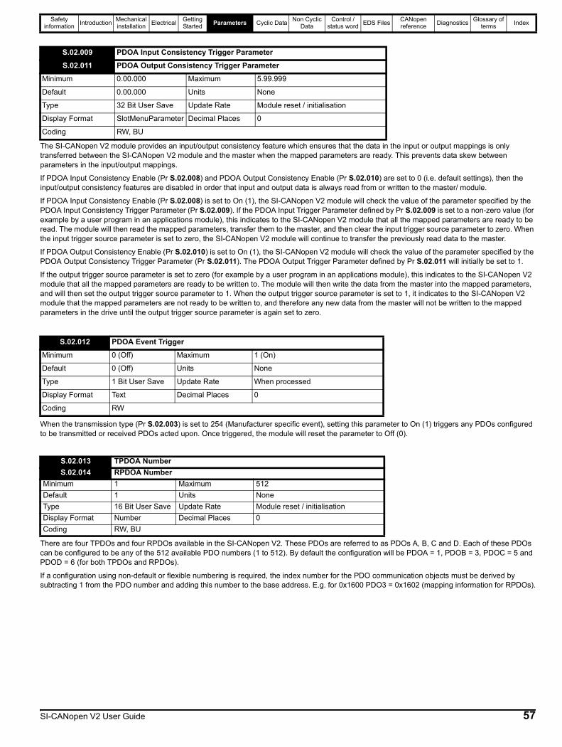
Safety information Introduction Mechanical
installation Electrical Getting Started Parameters Cyclic Data Non Cyclic
DataControl /
status word EDS Files CANopen reference Diagnostics Glossary of
terms Index
The SI-CANopen V2 module provides an input/output consistency feature which ensures that the data in the input or output mappings is only transferred between the SI-CANopen V2 module and the master when the mapped parameters are ready. This prevents data skew between parameters in the input/output mappings.
If PDOA Input Consistency Enable (Pr S.02.008) and PDOA Output Consistency Enable (Pr S.02.010) are set to 0 (i.e. default settings), then the input/output consistency features are disabled in order that input and output data is always read from or written to the master/ module.
If PDOA Input Consistency Enable (Pr S.02.008) is set to On (1), the SI-CANopen V2 module will check the value of the parameter specified by the PDOA Input Consistency Trigger Parameter (Pr S.02.009). If the PDOA Input Trigger Parameter defined by Pr S.02.009 is set to a non-zero value (for example by a user program in an applications module), this indicates to the SI-CANopen V2 module that all the mapped parameters are ready to be read. The module will then read the mapped parameters, transfer them to the master, and then clear the input trigger source parameter to zero. When the input trigger source parameter is set to zero, the SI-CANopen V2 module will continue to transfer the previously read data to the master.
If PDOA Output Consistency Enable (Pr S.02.010) is set to On (1), the SI-CANopen V2 module will check the value of the parameter specified by the PDOA Output Consistency Trigger Parameter (Pr S.02.011). The PDOA Output Trigger Parameter defined by Pr S.02.011 will initially be set to 1.
If the output trigger source parameter is set to zero (for example by a user program in an applications module), this indicates to the SI-CANopen V2 module that all the mapped parameters are ready to be written to. The module will then write the data from the master into the mapped parameters, and will then set the output trigger source parameter to 1. When the output trigger source parameter is set to 1, it indicates to the SI-CANopen V2 module that the mapped parameters are not ready to be written to, and therefore any new data from the master will not be written to the mapped parameters in the drive until the output trigger source parameter is again set to zero.
When the transmission type (Pr S.02.003) is set to 254 (Manufacturer specific event), setting this parameter to On (1) triggers any PDOs configured to be transmitted or received PDOs acted upon. Once triggered, the module will reset the parameter to Off (0).
There are four TPDOs and four RPDOs available in the SI-CANopen V2. These PDOs are referred to as PDOs A, B, C and D. Each of these PDOs can be configured to be any of the 512 available PDO numbers (1 to 512). By default the configuration will be PDOA = 1, PDOB = 3, PDOC = 5 and PDOD = 6 (for both TPDOs and RPDOs).
If a configuration using non-default or flexible numbering is required, the index number for the PDO communication objects must be derived by subtracting 1 from the PDO number and adding this number to the base address. E.g. for 0x1600 PDO3 = 0x1602 (mapping information for RPDOs).
S.02.009 PDOA Input Consistency Trigger ParameterS.02.011 PDOA Output Consistency Trigger Parameter
Minimum 0.00.000 Maximum 5.99.999
Default 0.00.000 Units None
Type 32 Bit User Save Update Rate Module reset / initialisation
Display Format SlotMenuParameter Decimal Places 0
Coding RW, BU
S.02.012 PDOA Event TriggerMinimum 0 (Off) Maximum 1 (On)
Default 0 (Off) Units None
Type 1 Bit User Save Update Rate When processed
Display Format Text Decimal Places 0
Coding RW
S.02.013 TPDOA NumberS.02.014 RPDOA Number
Minimum 1 Maximum 512Default 1 Units NoneType 16 Bit User Save Update Rate Module reset / initialisationDisplay Format Number Decimal Places 0Coding RW, BU
SI-CANopen V2 User Guide 57

Safety information Introduction Mechanical
installation Electrical Getting Started Parameters Cyclic Data Non Cyclic
DataControl /
status word EDS Files CANopen reference Diagnostics Glossary of
terms Index
Parameters S.02.015 - S.02.018 are used to define the application objects which are mapped to TPDOA.
Parameters S.02.019 - S.02.022 are used to define the application objects which are mapped to RPDOA.
By default, SI-CANopen V2 will use 32 bits for each mapped parameter data, irrespective of the actual data size of the parameter. For more information please see Pr S.01.014 (Data Alignment).
The defaults of all the mapping parameters are as follows:
S.02.015 TPDOA Mapping Parameter 1S.02.016 TPDOA Mapping Parameter 2S.02.017 TPDOA Mapping Parameter 3S.02.018 TPDOA Mapping Parameter 4S.02.019 RPDOA Mapping Parameter 1S.02.020 RPDOA Mapping Parameter 2S.02.021 RPDOA Mapping Parameter 3S.02.022 RPDOA Mapping Parameter 4
Minimum 0.00.000 Maximum 5.99.999Default See below Units NoneType 32 Bit User Save Update Rate Module reset / initialisationDisplay Format SlotMenuParameter Decimal Places 0Coding RW, BU
Parameter Default DescriptionTPDOA Mapping Parameter 1 (Pr S.02.015) 0.10.040 Status WordTPDOA Mapping Parameter 2 (Pr S.02.016) 0.02.001 Post Ramp ReferenceTPDOA Mapping Parameter 3 (Pr S.02.017) 0.00.000 Not usedTPDOA Mapping Parameter 4 (Pr S.02.018) 0.00.000 Not usedRPDOA Mapping Parameter 1 (Pr S.02.019) 0.06.042 Control WordRPDOA Mapping Parameter 2 (Pr S.02.020) 0.01.021 Preset Reference 1RPDOA Mapping Parameter 3 (Pr S.02.021) 0.00.000 Not usedRPDOA Mapping Parameter 4 (Pr S.02.022) 0.00.000 Not used
NOTE
58 SI-CANopen V2 User Guide
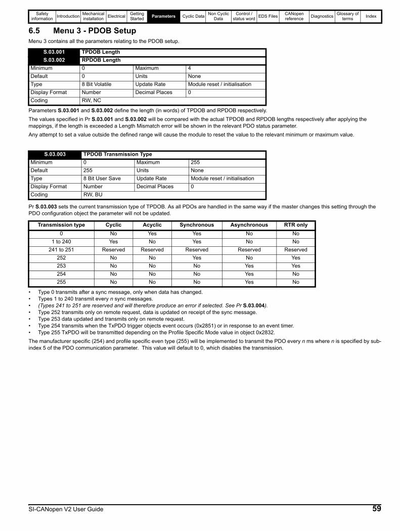
Safety information Introduction Mechanical
installation Electrical Getting Started Parameters Cyclic Data Non Cyclic
DataControl /
status word EDS Files CANopen reference Diagnostics Glossary of
terms Index
6.5 Menu 3 - PDOB SetupMenu 3 contains all the parameters relating to the PDOB setup.
Parameters S.03.001 and S.03.002 define the length (in words) of TPDOB and RPDOB respectively.The values specified in Pr S.03.001 and S.03.002 will be compared with the actual TPDOB and RPDOB lengths respectively after applying the mappings, if the length is exceeded a Length Mismatch error will be shown in the relevant PDO status parameter.Any attempt to set a value outside the defined range will cause the module to reset the value to the relevant minimum or maximum value.
Pr S.03.003 sets the current transmission type of TPDOB. As all PDOs are handled in the same way if the master changes this setting through the PDO configuration object the parameter will not be updated.
• Type 0 transmits after a sync message, only when data has changed.• Types 1 to 240 transmit every n sync messages.• (Types 241 to 251 are reserved and will therefore produce an error if selected. See Pr S.03.004).• Type 252 transmits only on remote request, data is updated on receipt of the sync message.• Type 253 data updated and transmits only on remote request.• Type 254 transmits when the TxPDO trigger objects event occurs (0x2851) or in response to an event timer.• Type 255 TxPDO will be transmitted depending on the Profile Specific Mode value in object 0x2832.The manufacturer specific (254) and profile specific even type (255) will be implemented to transmit the PDO every n ms where n is specified by sub-index 5 of the PDO communication parameter. This value will default to 0, which disables the transmission.
S.03.001 TPDOB LengthS.03.002 RPDOB Length
Minimum 0 Maximum 4Default 0 Units NoneType 8 Bit Volatile Update Rate Module reset / initialisationDisplay Format Number Decimal Places 0Coding RW, NC
S.03.003 TPDOB Transmission TypeMinimum 0 Maximum 255Default 255 Units NoneType 8 Bit User Save Update Rate Module reset / initialisationDisplay Format Number Decimal Places 0Coding RW, BU
Transmission type Cyclic Acyclic Synchronous Asynchronous RTR only0 No Yes Yes No No
1 to 240 Yes No Yes No No241 to 251 Reserved Reserved Reserved Reserved Reserved
252 No No Yes No Yes253 No No No Yes Yes254 No No No Yes No255 No No No Yes No
SI-CANopen V2 User Guide 59
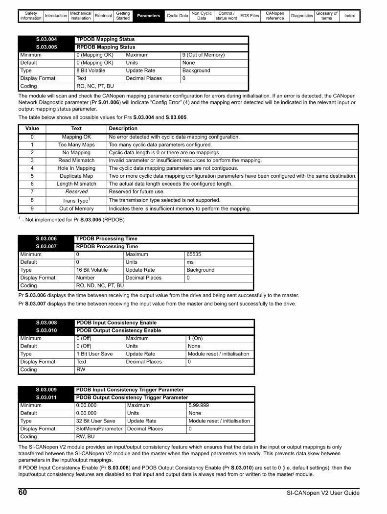
Safety information Introduction Mechanical
installation Electrical Getting Started Parameters Cyclic Data Non Cyclic
DataControl /
status word EDS Files CANopen reference Diagnostics Glossary of
terms Index
The module will scan and check the CANopen mapping parameter configuration for errors during initialisation. If an error is detected, the CANopen Network Diagnostic parameter (Pr S.01.006) will indicate “Config Error” (4) and the mapping error detected will be indicated in the relevant input or output mapping status parameter.The table below shows all possible values for Prs S.03.004 and S.03.005.
1 - Not implemented for Pr S.03.005 (RPDOB)
Pr S.03.006 displays the time between receiving the output value from the drive and being sent successfully to the master.Pr S.03.007 displays the time between receiving the input value from the master and being sent successfully to the drive.
The SI-CANopen V2 module provides an input/output consistency feature which ensures that the data in the input or output mappings is only transferred between the SI-CANopen V2 module and the master when the mapped parameters are ready. This prevents data skew between parameters in the input/output mappings.If PDOB Input Consistency Enable (Pr S.03.008) and PDOB Output Consistency Enable (Pr S.03.010) are set to 0 (i.e. default settings), then the input/output consistency features are disabled so that input and output data is always read from or written to the master/ module.
S.03.004 TPDOB Mapping StatusS.03.005 RPDOB Mapping Status
Minimum 0 (Mapping OK) Maximum 9 (Out of Memory)Default 0 (Mapping OK) Units NoneType 8 Bit Volatile Update Rate BackgroundDisplay Format Text Decimal Places 0Coding RO, NC, PT, BU
Value Text Description0 Mapping OK No error detected with cyclic data mapping configuration.1 Too Many Maps Too many cyclic data parameters configured.2 No Mapping Cyclic data length is 0 or there are no mappings.3 Read Mismatch Invalid parameter or insufficient resources to perform the mapping.4 Hole In Mapping The cyclic data mapping parameters are not contiguous.5 Duplicate Map Two or more cyclic data mapping configuration parameters have been configured with the same destination.6 Length Mismatch The actual data length exceeds the configured length.7 Reserved Reserved for future use.8 Trans Type1 The transmission type selected is not supported.9 Out of Memory Indicates there is insufficient memory to perform the mapping.
S.03.006 TPDOB Processing TimeS.03.007 RPDOB Processing Time
Minimum 0 Maximum 65535Default 0 Units msType 16 Bit Volatile Update Rate BackgroundDisplay Format Number Decimal Places 0Coding RO, ND, NC, PT, BU
S.03.008 PDOB Input Consistency EnableS.03.010 PDOB Output Consistency Enable
Minimum 0 (Off) Maximum 1 (On)Default 0 (Off) Units NoneType 1 Bit User Save Update Rate Module reset / initialisationDisplay Format Text Decimal Places 0Coding RW
S.03.009 PDOB Input Consistency Trigger ParameterS.03.011 PDOB Output Consistency Trigger Parameter
Minimum 0.00.000 Maximum 5.99.999Default 0.00.000 Units NoneType 32 Bit User Save Update Rate Module reset / initialisationDisplay Format SlotMenuParameter Decimal Places 0Coding RW, BU
60 SI-CANopen V2 User Guide

Safety information Introduction Mechanical
installation Electrical Getting Started Parameters Cyclic Data Non Cyclic
DataControl /
status word EDS Files CANopen reference Diagnostics Glossary of
terms Index
If PDOB Input Consistency Enable (Pr S.03.008) is set to On (1), the SI-CANopen V2 module will check the value of the parameter specified by the PDOB Input Consistency Trigger Parameter (Pr S.03.009). If the PDOB Input Trigger Parameter defined by Pr S.03.009 is set to a non-zero value (for example by a user program in an applications module), this indicates to the SI-CANopen V2 module that all the mapped parameters are ready to be read. The module will then read the mapped parameters, transfer them to the master and will then clear the input trigger source parameter to zero. When the input trigger source parameter is set to zero, the SI-CANopen V2 module will continue to transfer the previously read data to the master.If PDOB Output Consistency Enable (Pr S.03.010) is set to On (1), the SI-CANopen V2 module will check the value of the parameter specified by the PDOB Output Consistency Trigger Parameter (Pr S.03.011). The PDOB Output Trigger Parameter defined by Pr S.03.011 will initially be set to 1.If the output trigger source parameter is set to zero (for example by a user program in an applications module), this indicates to the SI-CANopen V2 module that all the mapped parameters are ready to be written to. The module will then write the data from the master into the mapped parameters, and will then set the output trigger source parameter to 1. When the output trigger source parameter is set to 1, it indicates to the SI-CANopen V2 module that the mapped parameters are not ready to be written to, and therefore any new data from the master will not be written to the mapped parameters in the drive until the output trigger source parameter is again set to zero.
When the transmission type (Pr S.03.003) is set to 254 (Manufacturer specific event), setting this parameter to On (1) triggers any PDOs configured to be transmitted or received PDOs acted upon. Once triggered, the module will reset the parameter to Off (0).
There are four TPDOs and four RPDOs available in the SI-CANopen V2. These PDOs are referred to as PDOs A, B, C and D. Each of these PDOs can be configured to be any of the 512 available PDO numbers (1 to 512). By default the configuration will be PDOA = 1, PDOB = 3, PDOC = 5 and PDOD = 6 (for both TPDOs and RPDOs).If a configuration using non-default or flexible numbering is required, the index number for the PDO communication objects must be derived by subtracting 1 from the PDO number and adding this number to the base address, e.g. for 0x1600 PDO3 = 0x1602 (mapping information for RPDOs).
Parameters S.03.015 – S.03.018 are used to define the application objects which are mapped to TPDOB.Parameters S.03.019 – S.03.022 are used to define the application objects which are mapped to RPDOB.
By default, SI-CANopen V2 will use 32 bits for each mapped parameter data, irrespective of the actual data size of the parameter. For more information please see Pr S.01.014 (Data Alignment).
S.03.012 PDOB Event TriggerMinimum 0 (Off) Maximum 1 (On)Default 0 (Off) Units NoneType 1 Bit User Save Update Rate When processedDisplay Format Text Decimal Places 0Coding RW
S.03.013 TPDOB NumberS.03.014 RPDOB Number
Minimum 1 Maximum 512Default 3 Units NoneType 16 Bit User Save Update Rate Module reset / initialisationDisplay Format Number Decimal Places 0Coding RW, BU
S.03.015 TPDOB Mapping Parameter 1S.03.016 TPDOB Mapping Parameter 2S.03.017 TPDOB Mapping Parameter 3S.03.018 TPDOB Mapping Parameter 4S.03.019 RPDOB Mapping Parameter 1S.03.020 RPDOB Mapping Parameter 2S.03.021 RPDOB Mapping Parameter 3S.03.022 RPDOB Mapping Parameter 4
Minimum 0.00.000 Maximum 5.99.999Default 0.00.000 Units NoneType 32 Bit User Save Update Rate Module reset / initialisationDisplay Format SlotMenuParameter Decimal Places 0Coding RW, BU
NOTE
SI-CANopen V2 User Guide 61
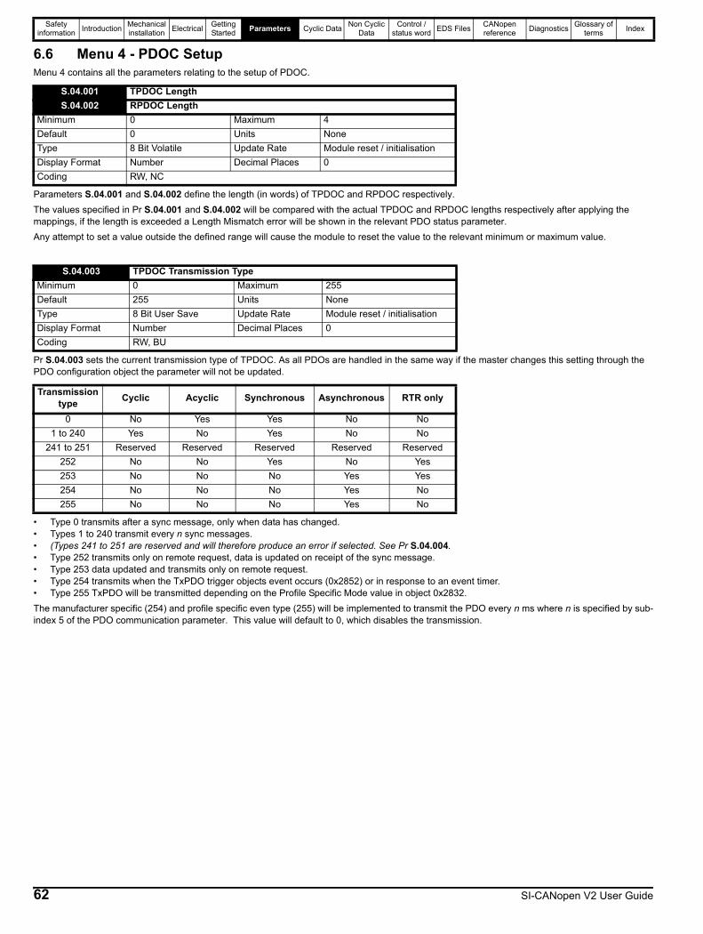
Safety information Introduction Mechanical
installation Electrical Getting Started Parameters Cyclic Data Non Cyclic
DataControl /
status word EDS Files CANopen reference Diagnostics Glossary of
terms Index
6.6 Menu 4 - PDOC SetupMenu 4 contains all the parameters relating to the setup of PDOC.
Parameters S.04.001 and S.04.002 define the length (in words) of TPDOC and RPDOC respectively.The values specified in Pr S.04.001 and S.04.002 will be compared with the actual TPDOC and RPDOC lengths respectively after applying the mappings, if the length is exceeded a Length Mismatch error will be shown in the relevant PDO status parameter.Any attempt to set a value outside the defined range will cause the module to reset the value to the relevant minimum or maximum value.
Pr S.04.003 sets the current transmission type of TPDOC. As all PDOs are handled in the same way if the master changes this setting through the PDO configuration object the parameter will not be updated.
• Type 0 transmits after a sync message, only when data has changed.• Types 1 to 240 transmit every n sync messages.• (Types 241 to 251 are reserved and will therefore produce an error if selected. See Pr S.04.004.• Type 252 transmits only on remote request, data is updated on receipt of the sync message.• Type 253 data updated and transmits only on remote request.• Type 254 transmits when the TxPDO trigger objects event occurs (0x2852) or in response to an event timer.• Type 255 TxPDO will be transmitted depending on the Profile Specific Mode value in object 0x2832.The manufacturer specific (254) and profile specific even type (255) will be implemented to transmit the PDO every n ms where n is specified by sub-index 5 of the PDO communication parameter. This value will default to 0, which disables the transmission.
S.04.001 TPDOC LengthS.04.002 RPDOC Length
Minimum 0 Maximum 4Default 0 Units NoneType 8 Bit Volatile Update Rate Module reset / initialisationDisplay Format Number Decimal Places 0Coding RW, NC
S.04.003 TPDOC Transmission TypeMinimum 0 Maximum 255Default 255 Units NoneType 8 Bit User Save Update Rate Module reset / initialisationDisplay Format Number Decimal Places 0Coding RW, BU
Transmission type Cyclic Acyclic Synchronous Asynchronous RTR only
0 No Yes Yes No No1 to 240 Yes No Yes No No
241 to 251 Reserved Reserved Reserved Reserved Reserved252 No No Yes No Yes253 No No No Yes Yes254 No No No Yes No255 No No No Yes No
62 SI-CANopen V2 User Guide
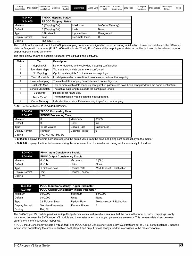
Safety information Introduction Mechanical
installation Electrical Getting Started Parameters Cyclic Data Non Cyclic
DataControl /
status word EDS Files CANopen reference Diagnostics Glossary of
terms Index
The module will scan and check the CANopen mapping parameter configuration for errors during initialisation. If an error is detected, the CANopen Network Diagnostic parameter (Pr S.01.006) will indicate “Config Error” (4) and the mapping error detected will be indicated in the relevant input or output mapping status parameter.The table below shows all possible values for Prs S.04.004 and S.04.005.
1 - Not implemented for Pr S.04.005 (RPDOC)
Pr S.04.006 displays the time between receiving the output value from the drive and being sent successfully to the master.Pr S.04.007 displays the time between receiving the input value from the master and being sent successfully to the drive.
The SI-CANopen V2 module provides an input/output consistency feature which ensures that the data in the input or output mappings is only transferred between the SI-CANopen V2 module and the master when the mapped parameters are ready. This prevents data skew between parameters in the input/output mappings.If PDOC Input Consistency Enable (Pr S.04.008) and PDOC Output Consistency Enable (Pr S.04.010) are set to 0 (i.e. default settings), then the input/output consistency features are disabled so that input and output data is always read from or written to the master/ module.
S.04.004 TPDOC Mapping StatusS.04.005 RPDOC Mapping Status
Minimum 0 (Mapping OK) Maximum 9 (Out of Memory)Default 0 (Mapping OK) Units NoneType 8 Bit Volatile Update Rate BackgroundDisplay Format Text Decimal Places 0Coding RO, NC, PT, BU
Value Text Description0 Mapping OK No error detected with cyclic data mapping configuration.1 Too Many Maps Too many cyclic data parameters configured.2 No Mapping Cyclic data length is 0 or there are no mappings.3 Read Mismatch Invalid parameter or insufficient resources to perform the mapping.4 Hole In Mapping The cyclic data mapping parameters are not contiguous.5 Duplicate Map Two or more cyclic data mapping configuration parameters have been configured with the same destination.6 Length Mismatch The actual data length exceeds the configured length.7 Reserved Reserved for future use.8 Trans Type1 The transmission type selected is not supported.
9 Out of Memory Indicates there is insufficient memory to perform the mapping.
S.04.006 TPDOC Processing TimeS.04.007 RPDOC Processing Time
Minimum 0 Maximum 65535Default 0 Units msType 16 Bit Volatile Update Rate BackgroundDisplay Format Number Decimal Places 0Coding RO, ND, NC, PT, BU
S.04.008 PDOC Input Consistency EnableS.04.010 PDOC Output Consistency Enable
Minimum 0 (Off) Maximum 1 (On)Default 0 (Off) Units NoneType 1 Bit User Save Update Rate Module reset / initialisationDisplay Format Text Decimal Places 0Coding RW
S.04.009 PDOC Input Consistency Trigger ParameterS.04.011 PDOC Output Consistency Trigger Parameter
Minimum 0.00.000 Maximum 5.99.999Default 0.00.000 Units NoneType 32 Bit User Save Update Rate Module reset / initializationDisplay Format SlotMenuParameter Decimal Places 0Coding RW, BU
SI-CANopen V2 User Guide 63
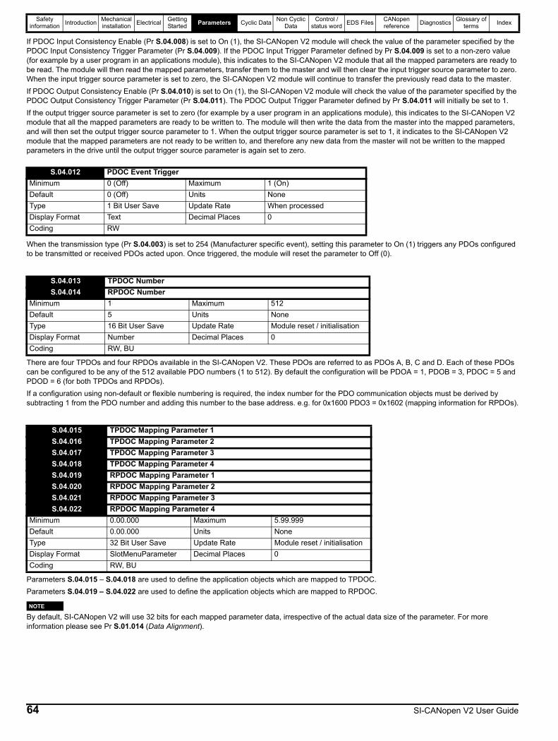
Safety information Introduction Mechanical
installation Electrical Getting Started Parameters Cyclic Data Non Cyclic
DataControl /
status word EDS Files CANopen reference Diagnostics Glossary of
terms Index
If PDOC Input Consistency Enable (Pr S.04.008) is set to On (1), the SI-CANopen V2 module will check the value of the parameter specified by the PDOC Input Consistency Trigger Parameter (Pr S.04.009). If the PDOC Input Trigger Parameter defined by Pr S.04.009 is set to a non-zero value (for example by a user program in an applications module), this indicates to the SI-CANopen V2 module that all the mapped parameters are ready to be read. The module will then read the mapped parameters, transfer them to the master and will then clear the input trigger source parameter to zero. When the input trigger source parameter is set to zero, the SI-CANopen V2 module will continue to transfer the previously read data to the master.If PDOC Output Consistency Enable (Pr S.04.010) is set to On (1), the SI-CANopen V2 module will check the value of the parameter specified by the PDOC Output Consistency Trigger Parameter (Pr S.04.011). The PDOC Output Trigger Parameter defined by Pr S.04.011 will initially be set to 1.If the output trigger source parameter is set to zero (for example by a user program in an applications module), this indicates to the SI-CANopen V2 module that all the mapped parameters are ready to be written to. The module will then write the data from the master into the mapped parameters, and will then set the output trigger source parameter to 1. When the output trigger source parameter is set to 1, it indicates to the SI-CANopen V2 module that the mapped parameters are not ready to be written to, and therefore any new data from the master will not be written to the mapped parameters in the drive until the output trigger source parameter is again set to zero.
When the transmission type (Pr S.04.003) is set to 254 (Manufacturer specific event), setting this parameter to On (1) triggers any PDOs configured to be transmitted or received PDOs acted upon. Once triggered, the module will reset the parameter to Off (0).
There are four TPDOs and four RPDOs available in the SI-CANopen V2. These PDOs are referred to as PDOs A, B, C and D. Each of these PDOs can be configured to be any of the 512 available PDO numbers (1 to 512). By default the configuration will be PDOA = 1, PDOB = 3, PDOC = 5 and PDOD = 6 (for both TPDOs and RPDOs).If a configuration using non-default or flexible numbering is required, the index number for the PDO communication objects must be derived by subtracting 1 from the PDO number and adding this number to the base address. e.g. for 0x1600 PDO3 = 0x1602 (mapping information for RPDOs).
Parameters S.04.015 – S.04.018 are used to define the application objects which are mapped to TPDOC.Parameters S.04.019 – S.04.022 are used to define the application objects which are mapped to RPDOC.
By default, SI-CANopen V2 will use 32 bits for each mapped parameter data, irrespective of the actual data size of the parameter. For more information please see Pr S.01.014 (Data Alignment).
S.04.012 PDOC Event TriggerMinimum 0 (Off) Maximum 1 (On)Default 0 (Off) Units NoneType 1 Bit User Save Update Rate When processedDisplay Format Text Decimal Places 0Coding RW
S.04.013 TPDOC NumberS.04.014 RPDOC Number
Minimum 1 Maximum 512Default 5 Units NoneType 16 Bit User Save Update Rate Module reset / initialisationDisplay Format Number Decimal Places 0Coding RW, BU
S.04.015 TPDOC Mapping Parameter 1S.04.016 TPDOC Mapping Parameter 2S.04.017 TPDOC Mapping Parameter 3S.04.018 TPDOC Mapping Parameter 4S.04.019 RPDOC Mapping Parameter 1S.04.020 RPDOC Mapping Parameter 2S.04.021 RPDOC Mapping Parameter 3S.04.022 RPDOC Mapping Parameter 4
Minimum 0.00.000 Maximum 5.99.999Default 0.00.000 Units NoneType 32 Bit User Save Update Rate Module reset / initialisationDisplay Format SlotMenuParameter Decimal Places 0Coding RW, BU
NOTE
64 SI-CANopen V2 User Guide

Safety information Introduction Mechanical
installation Electrical Getting Started Parameters Cyclic Data Non Cyclic
DataControl /
status word EDS Files CANopen reference Diagnostics Glossary of
terms Index
6.7 Menu 5 - PDOD SetupMenu 5 contains all the parameters relating the setup of PDOD.
Parameters S.05.001 and S.05.002 define the length (in words) of TPDOD and RPDOD respectively.The values specified in Pr S.05.001 and S.05.002 will be compared with the actual TPDOD and RPDOD lengths respectively after applying the mappings, if the length is exceeded a Length Mismatch error will be shown in the relevant PDO status parameter.Any attempt to set a value outside the defined range will cause the module to reset the value to the relevant minimum or maximum value.
Pr S.05.003 sets the current transmission type of TPDOD. As all PDOs are handled in the same way if the master changes this setting through the PDO configuration object the parameter will not be updated.
• Type 0 transmits after a sync message, only when data has changed.• Types 1 to 240 transmit every n sync messages.• (Types 241 to 251 are reserved and will therefore produce an error if selected. See Pr S.05.004).• Type 252 transmits only on remote request, data is updated on receipt of the sync message.• Type 253 data updated and transmits only on remote request.• Type 254 transmits when the TxPDO trigger objects event occurs (0x2853) or in response to an event timer.• Type 255 TxPDO will be transmitted depending on the Profile Specific Mode value in object 0x2832.The manufacturer specific (254) and profile specific even type (255) will be implemented to transmit the PDO every n ms where n is specified by sub-index 5 of the PDO communication parameter. This value will default to 0, which disables the transmission.
The module will scan and check the CANopen mapping parameter configuration for errors during initialisation. If an error is detected, the CANopen Network Diagnostic parameter (Pr S.01.006) will indicate “Config Error” (4) and the mapping error detected will be indicated in the relevant input or output mapping status parameter.
S.05.001 TPDOD LengthS.05.002 RPDOD Length
Minimum 0 Maximum 4Default 0 Units NoneType 8 Bit User Save Update Rate Module reset / initialisationDisplay Format Number Decimal Places 0Coding RW, NC
S.05.003 TPDOD Transmission TypeMinimum 0 Maximum 255Default 255 Units NoneType 8 Bit User Save Update Rate Module reset / initialisationDisplay Format Number Decimal Places 0Coding RW, BU
Transmission type Cyclic Acyclic Synchronous Asynchronous RTR only
0 No Yes Yes No No1 to 240 Yes No Yes No No
241 to 251 Reserved Reserved Reserved Reserved Reserved252 No No Yes No Yes253 No No No Yes Yes254 No No No Yes No255 No No No Yes No
S.05.004 TPDOD Mapping StatusS.05.005 RPDOD Mapping Status
Minimum 0 (Mapping OK) Maximum 9 (Out of Memory)Default 0 (Mapping OK) Units NoneType 8 Bit Volatile Update Rate BackgroundDisplay Format Text Decimal Places 0Coding RO, NC, PT, BU
SI-CANopen V2 User Guide 65
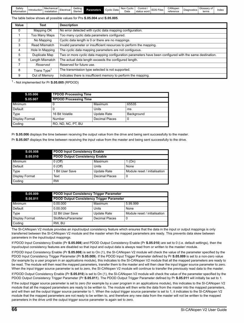
Safety information Introduction Mechanical
installation Electrical Getting Started Parameters Cyclic Data Non Cyclic
DataControl /
status word EDS Files CANopen reference Diagnostics Glossary of
terms Index
The table below shows all possible values for Prs S.05.004 and S.05.005.
1 - Not implemented for Pr S.05.005 (RPDOD)
Pr S.05.006 displays the time between receiving the output value from the drive and being sent successfully to the master.Pr S.05.007 displays the time between receiving the input value from the master and being sent successfully to the drive.
The SI-CANopen V2 module provides an input/output consistency feature which ensures that the data in the input or output mappings is only transferred between the SI-CANopen V2 module and the master when the mapped parameters are ready. This prevents data skew between parameters in the input/output mappings.If PDOD Input Consistency Enable (Pr S.05.008) and PDOD Output Consistency Enable (Pr S.05.010) are set to 0 (i.e. default settings), then the input/output consistency features are disabled so that input and output data is always read from or written to the master/ module.If PDOD Input Consistency Enable (Pr S.05.008) is set to On (1), the SI-CANopen V2 module will check the value of the parameter specified by the PDOD Input Consistency Trigger Parameter (Pr S.05.009). If the PDOD Input Trigger Parameter defined by Pr S.05.009 is set to a non-zero value (for example by a user program in an applications module), this indicates to the SI-CANopen V2 module that all the mapped parameters are ready to be read. The module will then read the mapped parameters, transfer them to the master and will then clear the input trigger source parameter to zero. When the input trigger source parameter is set to zero, the SI-CANopen V2 module will continue to transfer the previously read data to the master.If PDOD Output Consistency Enable (Pr S.05.010) is set to On (1), the SI-CANopen V2 module will check the value of the parameter specified by the PDOD Output Consistency Trigger Parameter (Pr S.05.011). The PDOD Output Trigger Parameter defined by Pr S.05.011 will initially be set to 1.If the output trigger source parameter is set to zero (for example by a user program in an applications module), this indicates to the SI-CANopen V2 module that all the mapped parameters are ready to be written to. The module will then write the data from the master into the mapped parameters, and will then set the output trigger source parameter to 1. When the output trigger source parameter is set to 1, it indicates to the SI-CANopen V2 module that the mapped parameters are not ready to be written to, and therefore any new data from the master will not be written to the mapped parameters in the drive until the output trigger source parameter is again set to zero.
Value Text Description0 Mapping OK No error detected with cyclic data mapping configuration.1 Too Many Maps Too many cyclic data parameters configured.2 No Mapping Cyclic data length is 0 or there are no mappings.3 Read Mismatch Invalid parameter or insufficient resources to perform the mapping.4 Hole In Mapping The cyclic data mapping parameters are not contiguous.5 Duplicate Map Two or more cyclic data mapping configuration parameters have been configured with the same destination.6 Length Mismatch The actual data length exceeds the configured length.7 Reserved Reserved for future use.8 Trans Type1 The transmission type selected is not supported.
9 Out of Memory Indicates there is insufficient memory to perform the mapping.
S.05.006 TPDOD Processing TimeS.05.007 RPDOD Processing Time
Minimum 0 Maximum 65535Default 0 Units msType 16 Bit Volatile Update Rate BackgroundDisplay Format Number Decimal Places 0Coding RO, ND, NC, PT, BU
S.05.008 PDOD Input Consistency EnableS.05.010 PDOD Output Consistency Enable
Minimum 0 (Off) Maximum 1 (On)Default 0 (Off) Units NoneType 1 Bit User Save Update Rate Module reset / initialisationDisplay Format Text Decimal Places 0Coding RW
S.05.009 PDOD Input Consistency Trigger ParameterS.05.011 PDOD Output Consistency Trigger Parameter
Minimum 0.00.000 Maximum 5.99.999Default 0.00.000 Units NoneType 32 Bit User Save Update Rate Module reset / initialisationDisplay Format SlotMenuParameter Decimal Places 0Coding RW, BU
66 SI-CANopen V2 User Guide

Safety information Introduction Mechanical
installation Electrical Getting Started Parameters Cyclic Data Non Cyclic
DataControl /
status word EDS Files CANopen reference Diagnostics Glossary of
terms Index
When the transmission type (Pr S.05.003) is set to 254 (Manufacturer specific event), setting this parameter to On (1) triggers any PDOs configured to be transmitted or received PDOs acted upon. Once triggered, the module will reset the parameter to Off (0).
There are four TPDOs and four RPDOs available in the SI-CANopen V2. These PDOs are referred to as PDOs A, B, C and D. Each of these PDOs can be configured to be any of the 512 available PDO numbers (1 to 512). By default the configuration will be PDOA = 1, PDOB = 3, PDOC = 5 and PDOD = 6 (for both TPDOs and RPDOs).If a configuration using non-default or flexible numbering is required, the index number for the PDO communication objects must be derived by subtracting 1 from the PDO number and adding this number to the base address. E.g. for 0x1600 PDO3 = 0x1602 (mapping information for RPDOs).
Parameters S.05.015 – S.05.018 are used to define the application objects which are mapped to TPDOD.Parameters S.05.019 – S.05.022 are used to define the application objects which are mapped to RPDOD.
By default, SI-CANopen V2 will use 32 bits for each mapped parameter data, irrespective of the actual data size of the parameter. For more information please see Pr S.01.014 (Data Alignment).
S.05.012 PDOD Event TriggerMinimum 0 (Off) Maximum 1 (On)Default 0 (Off) Units NoneType 1 Bit User Save Update Rate When processedDisplay Format Text Decimal Places 0Coding RW
S.05.013 TPDOD NumberS.05.014 RPDOD Number
Minimum 1 Maximum 512Default 6 Units NoneType 16 Bit User Save Update Rate Module reset / initialisationDisplay Format Number Decimal Places 0Coding RW, BU
S.05.015 TPDOD Mapping Parameter 1S.05.016 TPDOD Mapping Parameter 2S.05.017 TPDOD Mapping Parameter 3S.05.018 TPDOD Mapping Parameter 4S.05.019 RPDOD Mapping Parameter 1S.05.020 RPDOD Mapping Parameter 2S.05.021 RPDOD Mapping Parameter 3S.05.022 RPDOD Mapping Parameter 4
Minimum 0.00.000 Maximum 5.99.999Default 0.00.000 Units NoneType 32 Bit User Save Update Rate Module reset / initialisationDisplay Format SlotMenuParameter Decimal Places 0Coding RW, BU
NOTE
SI-CANopen V2 User Guide 67
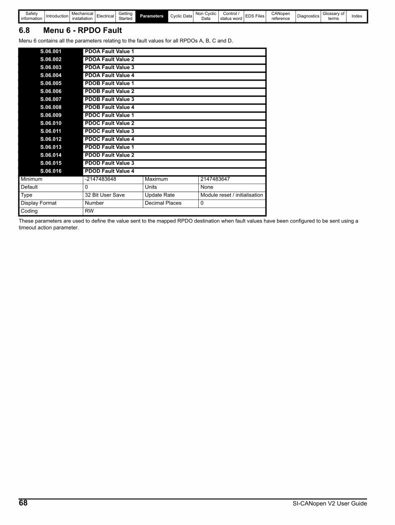
Safety information Introduction Mechanical
installation Electrical Getting Started Parameters Cyclic Data Non Cyclic
DataControl /
status word EDS Files CANopen reference Diagnostics Glossary of
terms Index
6.8 Menu 6 - RPDO FaultMenu 6 contains all the parameters relating to the fault values for all RPDOs A, B, C and D.
These parameters are used to define the value sent to the mapped RPDO destination when fault values have been configured to be sent using a timeout action parameter.
S.06.001 PDOA Fault Value 1S.06.002 PDOA Fault Value 2S.06.003 PDOA Fault Value 3S.06.004 PDOA Fault Value 4S.06.005 PDOB Fault Value 1S.06.006 PDOB Fault Value 2S.06.007 PDOB Fault Value 3S.06.008 PDOB Fault Value 4S.06.009 PDOC Fault Value 1S.06.010 PDOC Fault Value 2S.06.011 PDOC Fault Value 3S.06.012 PDOC Fault Value 4S.06.013 PDOD Fault Value 1S.06.014 PDOD Fault Value 2S.06.015 PDOD Fault Value 3S.06.016 PDOD Fault Value 4
Minimum -2147483648 Maximum 2147483647Default 0 Units NoneType 32 Bit User Save Update Rate Module reset / initialisationDisplay Format Number Decimal Places 0Coding RW
68 SI-CANopen V2 User Guide
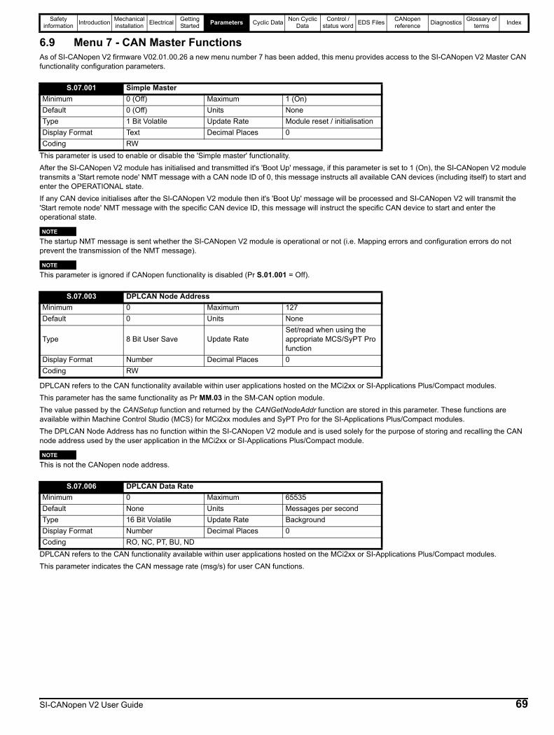
Safety information Introduction Mechanical
installation Electrical Getting Started Parameters Cyclic Data Non Cyclic
DataControl /
status word EDS Files CANopen reference Diagnostics Glossary of
terms Index
6.9 Menu 7 - CAN Master FunctionsAs of SI-CANopen V2 firmware V02.01.00.26 a new menu number 7 has been added, this menu provides access to the SI-CANopen V2 Master CAN functionality configuration parameters.
This parameter is used to enable or disable the 'Simple master' functionality.After the SI-CANopen V2 module has initialised and transmitted it's 'Boot Up' message, if this parameter is set to 1 (On), the SI-CANopen V2 module transmits a 'Start remote node' NMT message with a CAN node ID of 0, this message instructs all available CAN devices (including itself) to start and enter the OPERATIONAL state.If any CAN device initialises after the SI-CANopen V2 module then it's 'Boot Up' message will be processed and SI-CANopen V2 will transmit the 'Start remote node' NMT message with the specific CAN device ID, this message will instruct the specific CAN device to start and enter the operational state.
The startup NMT message is sent whether the SI-CANopen V2 module is operational or not (i.e. Mapping errors and configuration errors do not prevent the transmission of the NMT message).
This parameter is ignored if CANopen functionality is disabled (Pr S.01.001 = Off).
DPLCAN refers to the CAN functionality available within user applications hosted on the MCi2xx or SI-Applications Plus/Compact modules.This parameter has the same functionality as Pr MM.03 in the SM-CAN option module.The value passed by the CANSetup function and returned by the CANGetNodeAddr function are stored in this parameter. These functions are available within Machine Control Studio (MCS) for MCi2xx modules and SyPT Pro for the SI-Applications Plus/Compact modules.The DPLCAN Node Address has no function within the SI-CANopen V2 module and is used solely for the purpose of storing and recalling the CAN node address used by the user application in the MCi2xx or SI-Applications Plus/Compact module.
This is not the CANopen node address.
DPLCAN refers to the CAN functionality available within user applications hosted on the MCi2xx or SI-Applications Plus/Compact modules.This parameter indicates the CAN message rate (msg/s) for user CAN functions.
S.07.001 Simple MasterMinimum 0 (Off) Maximum 1 (On)Default 0 (Off) Units NoneType 1 Bit Volatile Update Rate Module reset / initialisationDisplay Format Text Decimal Places 0Coding RW
NOTE
NOTE
S.07.003 DPLCAN Node AddressMinimum 0 Maximum 127Default 0 Units None
Type 8 Bit User Save Update RateSet/read when using the appropriate MCS/SyPT Pro function
Display Format Number Decimal Places 0Coding RW
NOTE
S.07.006 DPLCAN Data RateMinimum 0 Maximum 65535Default None Units Messages per secondType 16 Bit Volatile Update Rate BackgroundDisplay Format Number Decimal Places 0Coding RO, NC, PT, BU, ND
SI-CANopen V2 User Guide 69
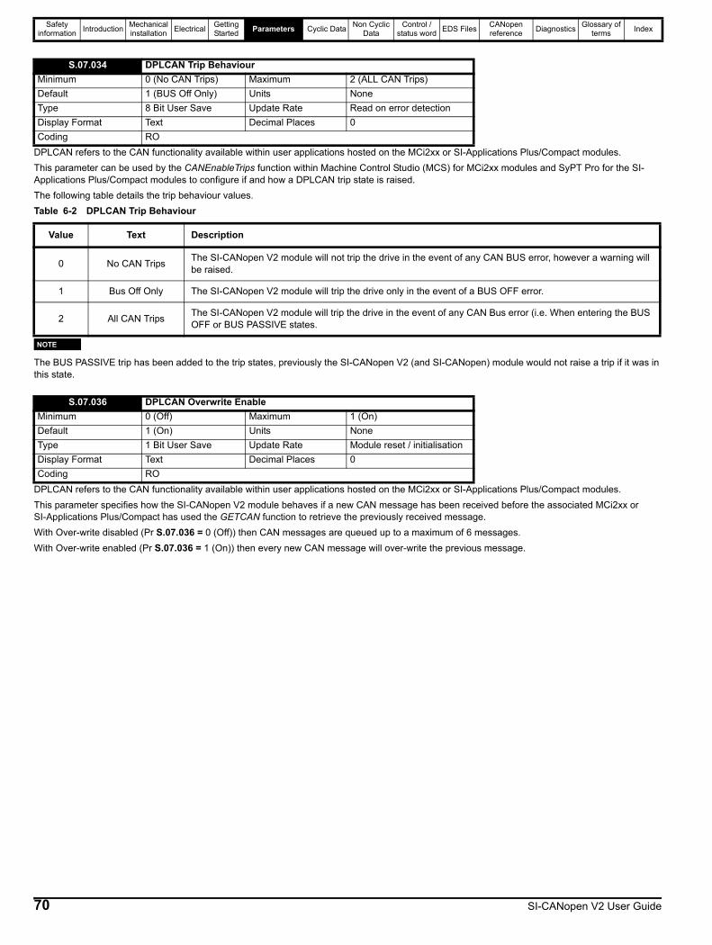
Safety information Introduction Mechanical
installation Electrical Getting Started Parameters Cyclic Data Non Cyclic
DataControl /
status word EDS Files CANopen reference Diagnostics Glossary of
terms Index
DPLCAN refers to the CAN functionality available within user applications hosted on the MCi2xx or SI-Applications Plus/Compact modules.This parameter can be used by the CANEnableTrips function within Machine Control Studio (MCS) for MCi2xx modules and SyPT Pro for the SI-Applications Plus/Compact modules to configure if and how a DPLCAN trip state is raised.The following table details the trip behaviour values.Table 6-2 DPLCAN Trip Behaviour
The BUS PASSIVE trip has been added to the trip states, previously the SI-CANopen V2 (and SI-CANopen) module would not raise a trip if it was in this state.
DPLCAN refers to the CAN functionality available within user applications hosted on the MCi2xx or SI-Applications Plus/Compact modules.This parameter specifies how the SI-CANopen V2 module behaves if a new CAN message has been received before the associated MCi2xx or SI-Applications Plus/Compact has used the GETCAN function to retrieve the previously received message.With Over-write disabled (Pr S.07.036 = 0 (Off)) then CAN messages are queued up to a maximum of 6 messages.With Over-write enabled (Pr S.07.036 = 1 (On)) then every new CAN message will over-write the previous message.
S.07.034 DPLCAN Trip BehaviourMinimum 0 (No CAN Trips) Maximum 2 (ALL CAN Trips)Default 1 (BUS Off Only) Units NoneType 8 Bit User Save Update Rate Read on error detectionDisplay Format Text Decimal Places 0Coding RO
Value Text Description
0 No CAN Trips The SI-CANopen V2 module will not trip the drive in the event of any CAN BUS error, however a warning will be raised.
1 Bus Off Only The SI-CANopen V2 module will trip the drive only in the event of a BUS OFF error.
2 All CAN Trips The SI-CANopen V2 module will trip the drive in the event of any CAN Bus error (i.e. When entering the BUS OFF or BUS PASSIVE states.
NOTE
S.07.036 DPLCAN Overwrite EnableMinimum 0 (Off) Maximum 1 (On)Default 1 (On) Units NoneType 1 Bit User Save Update Rate Module reset / initialisationDisplay Format Text Decimal Places 0Coding RO
70 SI-CANopen V2 User Guide
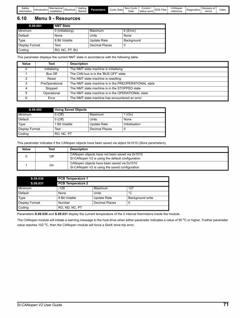
Safety information Introduction Mechanical
installation Electrical Getting Started Parameters Cyclic Data Non Cyclic
DataControl /
status word EDS Files CANopen reference Diagnostics Glossary of
terms Index
6.10 Menu 9 - Resources
This parameter displays the current NMT state in accordance with the following table.
This parameter indicates if the CANopen objects have been saved via object 0x1010 (Store parameters).
Parameters S.09.030 and S.09.031 display the current temperature of the 2 internal thermistors inside the module.
The CANopen module will initiate a warning message to the host drive when either parameter indicates a value of 95 oC or higher. If either parameter value reaches 102 oC, then the CANopen module will force a SlotX drive trip error.
S.09.001 NMT StateMinimum 0 (Initialising) Maximum 6 (Error)Default None Units NoneType 8 Bit Volatile Update Rate BackgroundDisplay Format Text Decimal Places 0Coding RO, NC, PT, BU
Value Text Description0 Initialising The NMT state machine is initialising1 Bus Off The CAN bus is in the 'BUS OFF' state2 Reset The NMT state machine is resetting3 PreOperational The NMT state machine is in the PREOPERATIONAL state4 Stopped The NMT state machine is in the STOPPED state5 Operational The NMT state machine is in the OPERATIONAL state6 Error The NMT state machine has encountered an error
S.09.002 Using Saved ObjectsMinimum 0 (Off) Maximum 1 (On)Default 0 (Off) Units NoneType 1 Bit Volatile Update Rate InitialisationDisplay Format Text Decimal Places 0Coding RO, NC, PT
Value Text Description
0 Off CANopen objects have not been saved via 0x1010SI-CANopen V2 is using the default configuration
1 On CANopen objects have been saved via 0x1010SI-CANopen V2 is using the saved configuration
S.09.030 PCB Temperature 1S.09.031 PCB Temperature 2
Minimum -128 Maximum 127Default None Units °CType 8 Bit Volatile Update Rate Background writeDisplay Format Number Decimal Places 0Coding RO, ND, NC, PT
SI-CANopen V2 User Guide 71

Safety information Introduction Mechanical
installation Electrical Getting Started Parameters Cyclic
DataNon Cyclic
DataControl /
status word EDS Files CANopen reference Diagnostics Glossary of
terms Index
7 Cyclic Data7.1 What is a “Process Data Object”?Cyclic data is implemented on CANopen networks by using “Process Data Objects” or PDOs. Separate data objects are used for transmitting (TxPDOs) and receiving (RxPDOs) data. PDO configuration objects are usually pre-configured in the CANopen master controller and downloaded to the CANopen device during initialisation using SDOs.
Mapping parameters are provided that can be used to configure each transmit and receive PDO separately. These parameters are used to set default values in the PDO mapping objects during initialisation.
7.1.1 Additional PDOs and device profilesSI-CANopen V2 supports a total of four PDOs, plus 4 device profiles. For further information on the CiA402 Device Profiles refer to section 11.41.
7.1.2 Duplicate mappingCare must be taken to ensure that there are no conflicts between the mapping of cyclic data and the analog and digital inputs within the drive itself. SI-CANopen V2 will not indicate if there is a conflict with drive mapping parameters.If a parameter is written to from two different sources, the value of this parameter will depend entirely upon the scan time for the parameter and the CANopen network cycle. This may cause the value in the parameter to change continuously between 2 values.
7.2 PDO data mapping errorsSI-CANopen V2 will scan and check the mapping parameter configuration for errors. If an error is detected, the drive will display an alarm; either ‘In Mapping’ or ‘Out Mapping’.
7.3 Unused PDO data channelsIf any data words are not being used in an application, the un-used mapping parameters should be set to 0. Although the data word will still be transmitted over the CANopen network, any incoming data will be discarded by SI-CANopen V2, and unmapped data words being passed back to the CANopen master controller will be set to 0.
7.4 Changing PDO mapping parameters (via controller/PLC)The mapping parameters for a PDO can only be modified when the number of mapped application objects in PDO (sub-index 0) is set to 0. This effectively disables the PDO while the mapping is modified using SDO communications.
Once all mapping parameters have been updated, the PDO sub-index 0 is set to specify the total number of defined mappings (normally 4 or 2). SI-CANopen V2 will calculate the PDO length from the mappings, and activate the changes to the PDO mappings.
7.5 Blank mapping parameters (via controller/PLC)If multiple CANopen nodes are configured with the same COB-ID for an RxPDO, they will all receive the RxPDO at the same time. For example, in a system comprising four drives, RxPDO1 could be used to transmit a 16-bit speed reference to each node.
However, the RxPDO1 mapping in each node must be configured to use only one word received on RxPDO1, and discard all other words. This can be achieved by creating a “blank mapping”. For an RxPDO, data with a blank mapping will simply be discarded. TxPDO data values with a blank mapping will be set to 0.
Slot parameters (Pr S.mm.ppp) are only required for configuration of the first PDO when configuration is done without SDOs. Configuration should normally be done with SDOs, if supported by the master.
If the CANopen master controller over-writes the mapping objects, the mapping parameters are NOT automatically updated to indicate the new mappings, in the corresponding slot menus. TxPDO and RxPDO describe the direction of data transfer as seen by the nodes on a SI-CANopen network. By default TxPDOA (default TxPDO1) is configured as transmission type 255.
Table 7-1 Blank mapping objects
Index Object code Name Type Access PDO mapping0x0002 DEFTYPE INTEGER8 INTEGER8 RW Yes0x0003 DEFTYPE INTEGER16 INTEGER16 RW Yes0x0004 DEFTYPE INTEGER32 INTEGER32 RW Yes0x0005 DEFTYPE UNSIGNED8 UNSIGNED8 RW Yes0x0006 DEFTYPE UNSIGNED16 UNSIGNED16 RW Yes0x0007 DEFTYPE UNSIGNED32 UNSIGNED32 RW Yes
NOTE
NOTE
72 SI-CANopen V2 User Guide

Safety information Introduction Mechanical
installation Electrical Getting Started Parameters Cyclic
DataNon Cyclic
DataControl /
status word EDS Files CANopen reference Diagnostics Glossary of
terms Index
Unwanted data should be mapped to the DEFTYPE object of appropriate size. Bytes, words and double words are supported, but the BOOLEAN TYPE IS NOT SUPPORTED. The only other limitation is that there are only four mapping parameters per PDO, due to memory restrictions.
For example, consider RxPDOA (by default PDO1) containing four 16-bit speed references, one each for four different nodes. If a node needs to access only the 3rd word of RxPDOA and map it to Pr 18.011, while ignoring the remaining words, the mapping configuration required is shown in Table 7-2.
Table 7-2 Example of blank mapping objects
Word Object Value0 0x1600sub1 0x000300101 0x1600sub2 0x000300102 0x1600sub3 0x20120B103 0x1600sub4 0x00030010
Blank mapping objects allow the mappings to contain null references that are not possible by other means.NOTE
SI-CANopen V2 User Guide 73
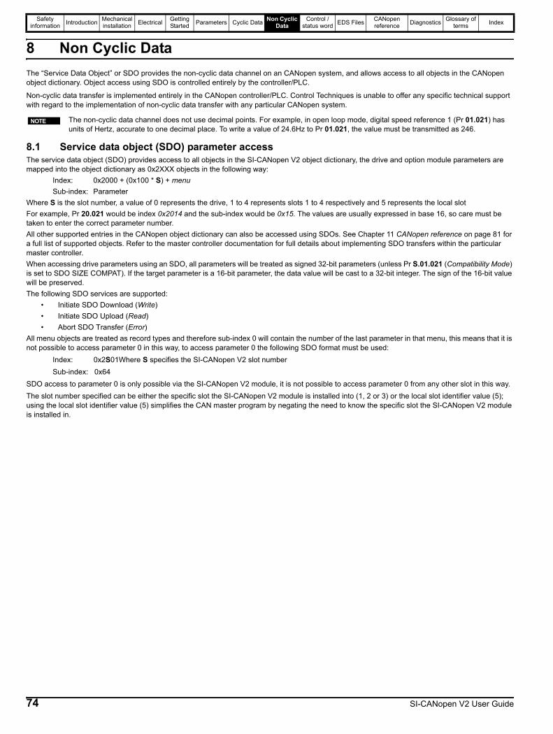
Safety information Introduction Mechanical
installation Electrical Getting Started Parameters Cyclic Data Non Cyclic
DataControl /
status word EDS Files CANopen reference Diagnostics Glossary of
terms Index
8 Non Cyclic DataThe “Service Data Object” or SDO provides the non-cyclic data channel on an CANopen system, and allows access to all objects in the CANopen object dictionary. Object access using SDO is controlled entirely by the controller/PLC.
Non-cyclic data transfer is implemented entirely in the CANopen controller/PLC. Control Techniques is unable to offer any specific technical support with regard to the implementation of non-cyclic data transfer with any particular CANopen system.
8.1 Service data object (SDO) parameter accessThe service data object (SDO) provides access to all objects in the SI-CANopen V2 object dictionary, the drive and option module parameters are mapped into the object dictionary as 0x2XXX objects in the following way:
Index: 0x2000 + (0x100 * S) + menuSub-index: Parameter
Where S is the slot number, a value of 0 represents the drive, 1 to 4 represents slots 1 to 4 respectively and 5 represents the local slotFor example, Pr 20.021 would be index 0x2014 and the sub-index would be 0x15. The values are usually expressed in base 16, so care must be taken to enter the correct parameter number.All other supported entries in the CANopen object dictionary can also be accessed using SDOs. See Chapter 11 CANopen reference on page 81 for a full list of supported objects. Refer to the master controller documentation for full details about implementing SDO transfers within the particular master controller.When accessing drive parameters using an SDO, all parameters will be treated as signed 32-bit parameters (unless Pr S.01.021 (Compatibility Mode) is set to SDO SIZE COMPAT). If the target parameter is a 16-bit parameter, the data value will be cast to a 32-bit integer. The sign of the 16-bit value will be preserved.The following SDO services are supported:
• Initiate SDO Download (Write)• Initiate SDO Upload (Read)• Abort SDO Transfer (Error)
All menu objects are treated as record types and therefore sub-index 0 will contain the number of the last parameter in that menu, this means that it is not possible to access parameter 0 in this way, to access parameter 0 the following SDO format must be used:
Index: 0x2S01Where S specifies the SI-CANopen V2 slot numberSub-index: 0x64
SDO access to parameter 0 is only possible via the SI-CANopen V2 module, it is not possible to access parameter 0 from any other slot in this way. The slot number specified can be either the specific slot the SI-CANopen V2 module is installed into (1, 2 or 3) or the local slot identifier value (5); using the local slot identifier value (5) simplifies the CAN master program by negating the need to know the specific slot the SI-CANopen V2 module is installed in.
The non-cyclic data channel does not use decimal points. For example, in open loop mode, digital speed reference 1 (Pr 01.021) has units of Hertz, accurate to one decimal place. To write a value of 24.6Hz to Pr 01.021, the value must be transmitted as 246.
NOTE
74 SI-CANopen V2 User Guide
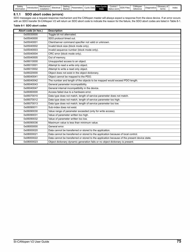
Safety information Introduction Mechanical
installation Electrical Getting Started Parameters Cyclic Data Non Cyclic
DataControl /
status word EDS Files CANopen reference Diagnostics Glossary of
terms Index
8.1.1 SDO abort codes (errors)SDO messages use a request-response mechanism and the CANopen master will always expect a response from the slave device. If an error occurs with an SDO transfer SI-CANopen V2 will return an SDO abort code to indicate the reason for the failure, the SDO abort codes are listed in Table 8-1.
Table 8-1 SDO abort codes
Abort code (in hex.) Description0x05030000 Toggle bit not alternated.0x05040000 SDO protocol timed out.0x05040001 Client/server command specifier not valid or unknown.0x05040002 Invalid block size (block mode only).0x05040003 Invalid sequence number (block mode only).0x05040004 CRC error (block mode only).0x05040005 Out of memory.0x06010000 Unsupported access to an object.0x06010001 Attempt to read a write only object.0x06010002 Attempt to write a read only object.0x06020000 Object does not exist in the object dictionary.0x06040041 Object cannot be mapped to the PDO.0x06040042 The number and length of the objects to be mapped would exceed PDO length.0x06040043 General parameter incompatibility.0x06040047 General internal incompatibility in the device.0x06060000 Access failed due to a hardware error.0x06070010 Data type does not match, length of service parameter does not match.0x06070012 Data type does not match, length of service parameter too high.0x06070013 Data type does not match, length of service parameter too low.0x06090011 Sub-index does not exist.0x06090030 Value range of parameter exceeded (only for write access).0x06090031 Value of parameter written too high.0x06090032 Value of parameter written too low.0x06090036 Maximum value is less than minimum value.0x08000000 General error.0x08000020 Data cannot be transferred or stored to the application.0x08000021 Data cannot be transferred or stored to the application because of local control.0x08000022 Data cannot be transferred or stored to the application because of the present device state.0x08000023 Object dictionary dynamic generation fails or no object dictionary is present.
SI-CANopen V2 User Guide 75
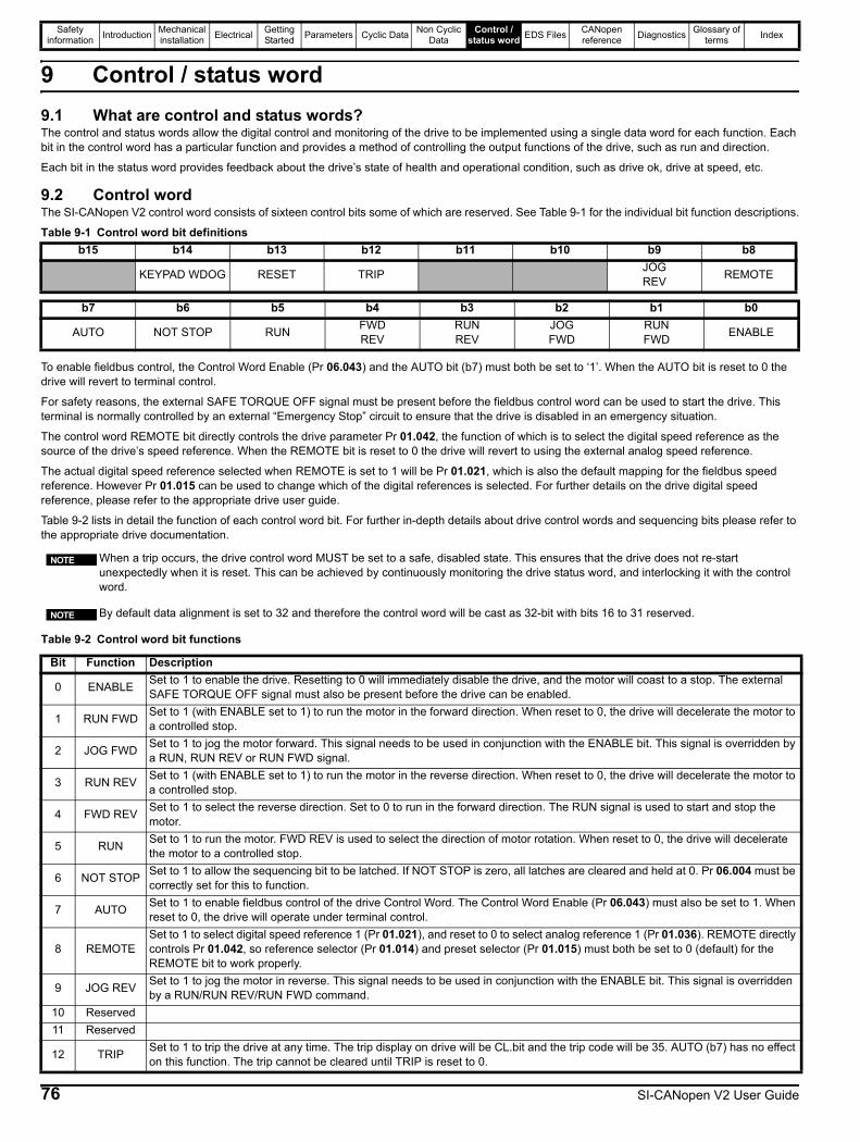
Safety information Introduction Mechanical
installation Electrical Getting Started Parameters Cyclic Data Non Cyclic
DataControl /
status word EDS Files CANopen reference Diagnostics Glossary of
terms Index
9 Control / status word9.1 What are control and status words?The control and status words allow the digital control and monitoring of the drive to be implemented using a single data word for each function. Each bit in the control word has a particular function and provides a method of controlling the output functions of the drive, such as run and direction.
Each bit in the status word provides feedback about the drive’s state of health and operational condition, such as drive ok, drive at speed, etc.
9.2 Control word The SI-CANopen V2 control word consists of sixteen control bits some of which are reserved. See Table 9-1 for the individual bit function descriptions.
Table 9-1 Control word bit definitions
To enable fieldbus control, the Control Word Enable (Pr 06.043) and the AUTO bit (b7) must both be set to ‘1’. When the AUTO bit is reset to 0 the drive will revert to terminal control.
For safety reasons, the external SAFE TORQUE OFF signal must be present before the fieldbus control word can be used to start the drive. This terminal is normally controlled by an external “Emergency Stop” circuit to ensure that the drive is disabled in an emergency situation.
The control word REMOTE bit directly controls the drive parameter Pr 01.042, the function of which is to select the digital speed reference as the source of the drive’s speed reference. When the REMOTE bit is reset to 0 the drive will revert to using the external analog speed reference.
The actual digital speed reference selected when REMOTE is set to 1 will be Pr 01.021, which is also the default mapping for the fieldbus speed reference. However Pr 01.015 can be used to change which of the digital references is selected. For further details on the drive digital speed reference, please refer to the appropriate drive user guide.
Table 9-2 lists in detail the function of each control word bit. For further in-depth details about drive control words and sequencing bits please refer to the appropriate drive documentation.
Table 9-2 Control word bit functions
b15 b14 b13 b12 b11 b10 b9 b8
KEYPAD WDOG RESET TRIP JOGREV REMOTE
b7 b6 b5 b4 b3 b2 b1 b0
AUTO NOT STOP RUN FWDREV
RUNREV
JOGFWD
RUNFWD ENABLE
When a trip occurs, the drive control word MUST be set to a safe, disabled state. This ensures that the drive does not re-start unexpectedly when it is reset. This can be achieved by continuously monitoring the drive status word, and interlocking it with the control word.
By default data alignment is set to 32 and therefore the control word will be cast as 32-bit with bits 16 to 31 reserved.
Bit Function Description
0 ENABLE Set to 1 to enable the drive. Resetting to 0 will immediately disable the drive, and the motor will coast to a stop. The external SAFE TORQUE OFF signal must also be present before the drive can be enabled.
1 RUN FWD Set to 1 (with ENABLE set to 1) to run the motor in the forward direction. When reset to 0, the drive will decelerate the motor to a controlled stop.
2 JOG FWD Set to 1 to jog the motor forward. This signal needs to be used in conjunction with the ENABLE bit. This signal is overridden by a RUN, RUN REV or RUN FWD signal.
3 RUN REV Set to 1 (with ENABLE set to 1) to run the motor in the reverse direction. When reset to 0, the drive will decelerate the motor to a controlled stop.
4 FWD REV Set to 1 to select the reverse direction. Set to 0 to run in the forward direction. The RUN signal is used to start and stop the motor.
5 RUN Set to 1 to run the motor. FWD REV is used to select the direction of motor rotation. When reset to 0, the drive will decelerate the motor to a controlled stop.
6 NOT STOP Set to 1 to allow the sequencing bit to be latched. If NOT STOP is zero, all latches are cleared and held at 0. Pr 06.004 must be correctly set for this to function.
7 AUTO Set to 1 to enable fieldbus control of the drive Control Word. The Control Word Enable (Pr 06.043) must also be set to 1. When reset to 0, the drive will operate under terminal control.
8 REMOTESet to 1 to select digital speed reference 1 (Pr 01.021), and reset to 0 to select analog reference 1 (Pr 01.036). REMOTE directly controls Pr 01.042, so reference selector (Pr 01.014) and preset selector (Pr 01.015) must both be set to 0 (default) for the REMOTE bit to work properly.
9 JOG REV Set to 1 to jog the motor in reverse. This signal needs to be used in conjunction with the ENABLE bit. This signal is overridden by a RUN/RUN REV/RUN FWD command.
10 Reserved11 Reserved
12 TRIP Set to 1 to trip the drive at any time. The trip display on drive will be CL.bit and the trip code will be 35. AUTO (b7) has no effect on this function. The trip cannot be cleared until TRIP is reset to 0.
NOTE
NOTE
76 SI-CANopen V2 User Guide
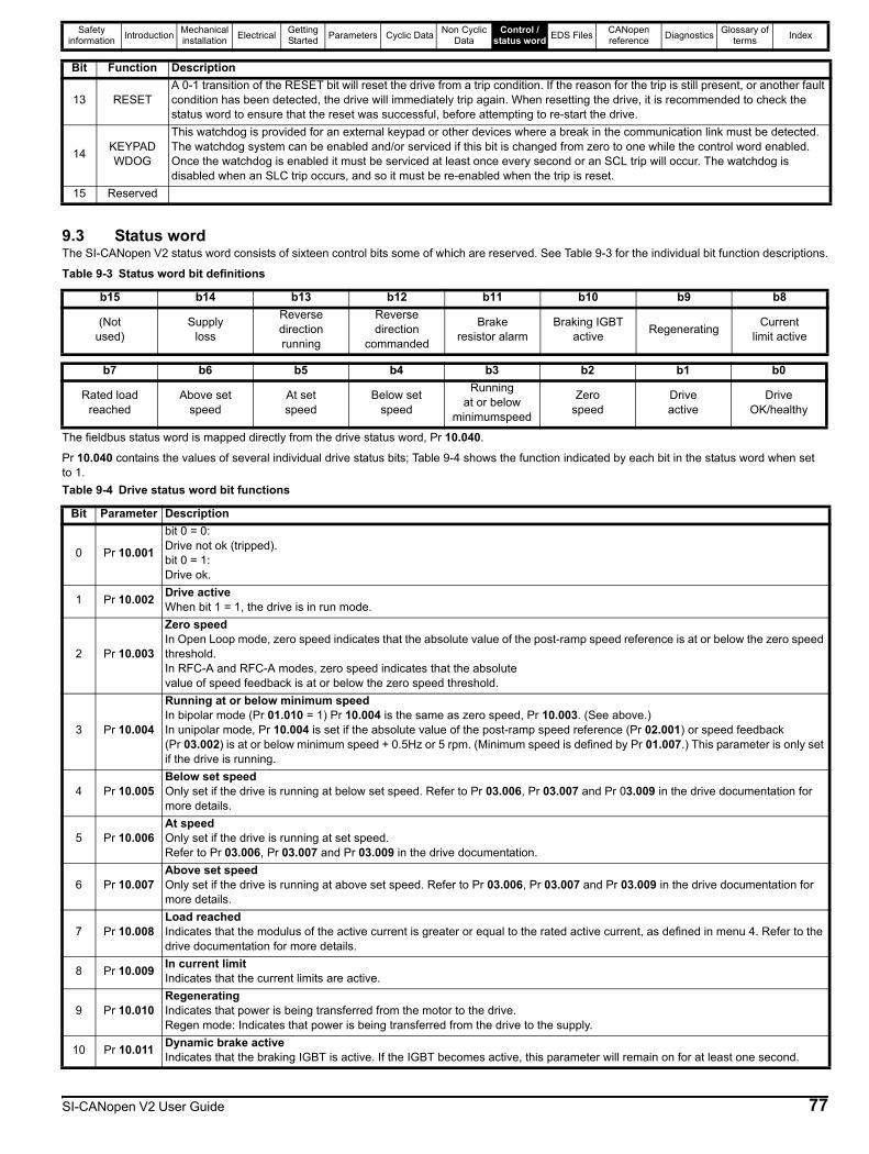
Safety information Introduction Mechanical
installation Electrical Getting Started Parameters Cyclic Data Non Cyclic
DataControl /
status word EDS Files CANopen reference Diagnostics Glossary of
terms Index
9.3 Status wordThe SI-CANopen V2 status word consists of sixteen control bits some of which are reserved. See Table 9-3 for the individual bit function descriptions.
Table 9-3 Status word bit definitions
The fieldbus status word is mapped directly from the drive status word, Pr 10.040.
Pr 10.040 contains the values of several individual drive status bits; Table 9-4 shows the function indicated by each bit in the status word when set to 1.Table 9-4 Drive status word bit functions
13 RESETA 0-1 transition of the RESET bit will reset the drive from a trip condition. If the reason for the trip is still present, or another fault condition has been detected, the drive will immediately trip again. When resetting the drive, it is recommended to check the status word to ensure that the reset was successful, before attempting to re-start the drive.
14 KEYPADWDOG
This watchdog is provided for an external keypad or other devices where a break in the communication link must be detected. The watchdog system can be enabled and/or serviced if this bit is changed from zero to one while the control word enabled.Once the watchdog is enabled it must be serviced at least once every second or an SCL trip will occur. The watchdog is disabled when an SLC trip occurs, and so it must be re-enabled when the trip is reset.
15 Reserved
b15 b14 b13 b12 b11 b10 b9 b8
(Notused)
Supplyloss
Reverse directionrunning
Reverse direction
commanded
Brakeresistor alarm
Braking IGBTactive Regenerating Current
limit active
b7 b6 b5 b4 b3 b2 b1 b0
Rated loadreached
Above setspeed
At setspeed
Below setspeed
Runningat or below
minimumspeed
Zerospeed
Driveactive
DriveOK/healthy
Bit Parameter Description
0 Pr 10.001
bit 0 = 0:Drive not ok (tripped).bit 0 = 1:Drive ok.
1 Pr 10.002 Drive activeWhen bit 1 = 1, the drive is in run mode.
2 Pr 10.003
Zero speedIn Open Loop mode, zero speed indicates that the absolute value of the post-ramp speed reference is at or below the zero speed threshold.In RFC-A and RFC-A modes, zero speed indicates that the absolutevalue of speed feedback is at or below the zero speed threshold.
3 Pr 10.004
Running at or below minimum speedIn bipolar mode (Pr 01.010 = 1) Pr 10.004 is the same as zero speed, Pr 10.003. (See above.)In unipolar mode, Pr 10.004 is set if the absolute value of the post-ramp speed reference (Pr 02.001) or speed feedback (Pr 03.002) is at or below minimum speed + 0.5Hz or 5 rpm. (Minimum speed is defined by Pr 01.007.) This parameter is only set if the drive is running.
4 Pr 10.005Below set speedOnly set if the drive is running at below set speed. Refer to Pr 03.006, Pr 03.007 and Pr 03.009 in the drive documentation for more details.
5 Pr 10.006At speedOnly set if the drive is running at set speed.Refer to Pr 03.006, Pr 03.007 and Pr 03.009 in the drive documentation.
6 Pr 10.007Above set speedOnly set if the drive is running at above set speed. Refer to Pr 03.006, Pr 03.007 and Pr 03.009 in the drive documentation for more details.
7 Pr 10.008Load reachedIndicates that the modulus of the active current is greater or equal to the rated active current, as defined in menu 4. Refer to the drive documentation for more details.
8 Pr 10.009 In current limitIndicates that the current limits are active.
9 Pr 10.010RegeneratingIndicates that power is being transferred from the motor to the drive.Regen mode: Indicates that power is being transferred from the drive to the supply.
10 Pr 10.011 Dynamic brake activeIndicates that the braking IGBT is active. If the IGBT becomes active, this parameter will remain on for at least one second.
Bit Function Description
SI-CANopen V2 User Guide 77

Safety information Introduction Mechanical
installation Electrical Getting Started Parameters Cyclic Data Non Cyclic
DataControl /
status word EDS Files CANopen reference Diagnostics Glossary of
terms Index
11 Pr 10.012 Dynamic brake alarmDynamic brake alarm is set when the braking IGBT is active, and the braking energy accumulator is greater than 75%.
12 Pr 10.013Reverse direction commandedDirection commanded is set to 1 if the Pre-ramp speed reference (Pr 01.003) is negative and reset to 0 if the Pre-ramp speed reference is zero or positive.
13 Pr 10.014Reverse direction runningA 0 indicates forward direction and a 1 indicates reverse direction. The source of this bit is Pr 02.001 for open loop mode and Pr 03.002 for RFC-A and RFC-S modes.
14 Pr 10.015
Supply loss Supply loss indicates that the drive has detected a supply loss from the level of the DC bus voltage. This parameter can only become active if supply loss ride through or supply loss stop modes are selected. In regen mode, supply loss is the inverse of Pr 03.007.
15 (Not Used) Reserved
Bit Parameter Description
78 SI-CANopen V2 User Guide
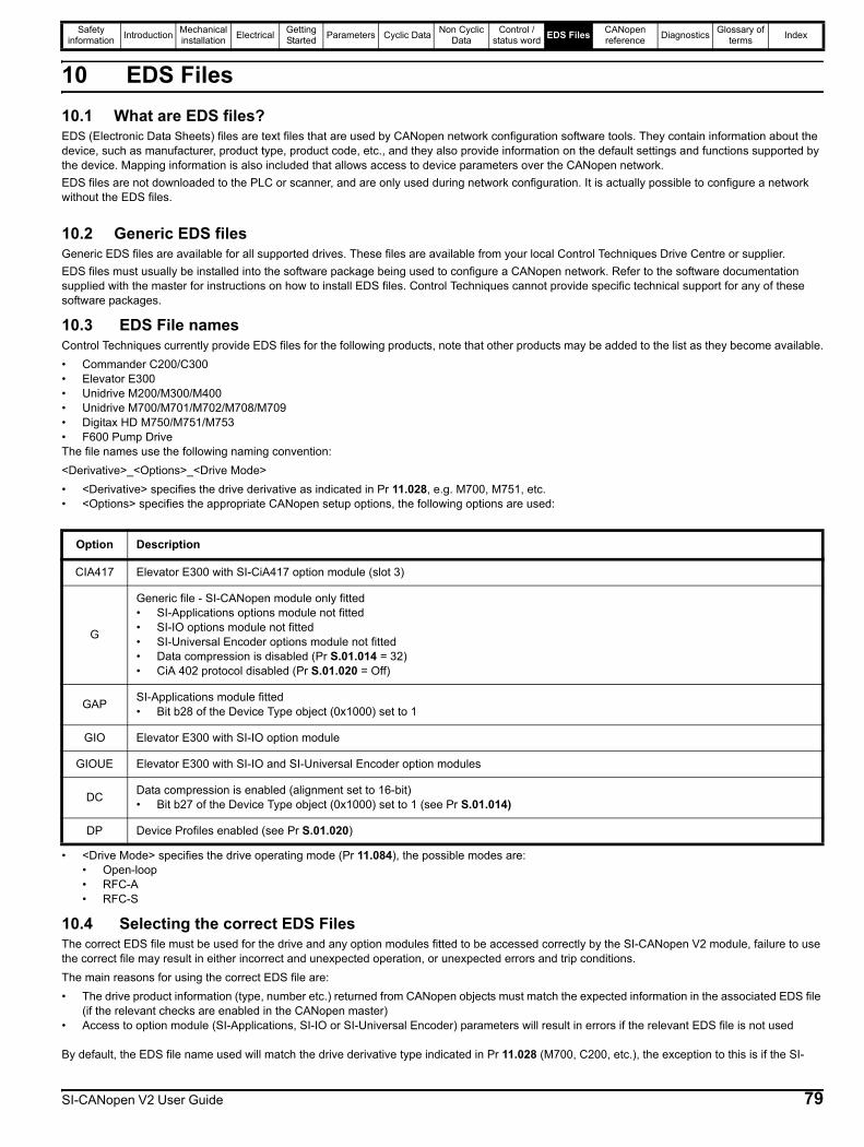
Safety information Introduction Mechanical
installation Electrical Getting Started Parameters Cyclic Data Non Cyclic
DataControl /
status word EDS Files CANopen reference Diagnostics Glossary of
terms Index
10 EDS Files10.1 What are EDS files?EDS (Electronic Data Sheets) files are text files that are used by CANopen network configuration software tools. They contain information about the device, such as manufacturer, product type, product code, etc., and they also provide information on the default settings and functions supported by the device. Mapping information is also included that allows access to device parameters over the CANopen network.EDS files are not downloaded to the PLC or scanner, and are only used during network configuration. It is actually possible to configure a network without the EDS files.
10.2 Generic EDS filesGeneric EDS files are available for all supported drives. These files are available from your local Control Techniques Drive Centre or supplier.EDS files must usually be installed into the software package being used to configure a CANopen network. Refer to the software documentation supplied with the master for instructions on how to install EDS files. Control Techniques cannot provide specific technical support for any of these software packages.
10.3 EDS File namesControl Techniques currently provide EDS files for the following products, note that other products may be added to the list as they become available.• Commander C200/C300• Elevator E300• Unidrive M200/M300/M400• Unidrive M700/M701/M702/M708/M709• Digitax HD M750/M751/M753• F600 Pump DriveThe file names use the following naming convention:<Derivative>_<Options>_<Drive Mode>• <Derivative> specifies the drive derivative as indicated in Pr 11.028, e.g. M700, M751, etc.• <Options> specifies the appropriate CANopen setup options, the following options are used:
• <Drive Mode> specifies the drive operating mode (Pr 11.084), the possible modes are:• Open-loop• RFC-A• RFC-S
10.4 Selecting the correct EDS FilesThe correct EDS file must be used for the drive and any option modules fitted to be accessed correctly by the SI-CANopen V2 module, failure to use the correct file may result in either incorrect and unexpected operation, or unexpected errors and trip conditions.The main reasons for using the correct EDS file are:• The drive product information (type, number etc.) returned from CANopen objects must match the expected information in the associated EDS file
(if the relevant checks are enabled in the CANopen master)• Access to option module (SI-Applications, SI-IO or SI-Universal Encoder) parameters will result in errors if the relevant EDS file is not used
By default, the EDS file name used will match the drive derivative type indicated in Pr 11.028 (M700, C200, etc.), the exception to this is if the SI-
Option Description
CIA417 Elevator E300 with SI-CiA417 option module (slot 3)
G
Generic file - SI-CANopen module only fitted• SI-Applications options module not fitted• SI-IO options module not fitted• SI-Universal Encoder options module not fitted• Data compression is disabled (Pr S.01.014 = 32)• CiA 402 protocol disabled (Pr S.01.020 = Off)
GAP SI-Applications module fitted• Bit b28 of the Device Type object (0x1000) set to 1
GIO Elevator E300 with SI-IO option module
GIOUE Elevator E300 with SI-IO and SI-Universal Encoder option modules
DC Data compression is enabled (alignment set to 16-bit)• Bit b27 of the Device Type object (0x1000) set to 1 (see Pr S.01.014)
DP Device Profiles enabled (see Pr S.01.020)
SI-CANopen V2 User Guide 79
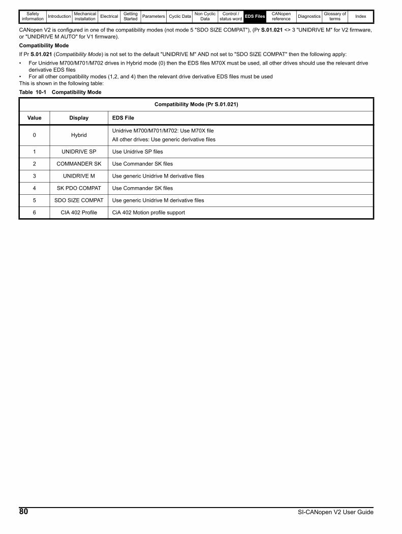
Safety information Introduction Mechanical
installation Electrical Getting Started Parameters Cyclic Data Non Cyclic
DataControl /
status word EDS Files CANopen reference Diagnostics Glossary of
terms Index
CANopen V2 is configured in one of the compatibility modes (not mode 5 "SDO SIZE COMPAT"), (Pr S.01.021 <> 3 "UNIDRIVE M" for V2 firmware, or "UNIDRIVE M AUTO" for V1 firmware).Compatibility ModeIf Pr S.01.021 (Compatibility Mode) is not set to the default "UNIDRIVE M" AND not set to "SDO SIZE COMPAT" then the following apply:• For Unidrive M700/M701/M702 drives in Hybrid mode (0) then the EDS files M70X must be used, all other drives should use the relevant drive
derivative EDS files• For all other compatibility modes (1,2, and 4) then the relevant drive derivative EDS files must be usedThis is shown in the following table:Table 10-1 Compatibility Mode
Compatibility Mode (Pr S.01.021)
Value Display EDS File
0 HybridUnidrive M700/M701/M702: Use M70X fileAll other drives: Use generic derivative files
1 UNIDRIVE SP Use Unidrive SP files
2 COMMANDER SK Use Commander SK files
3 UNIDRIVE M Use generic Unidrive M derivative files
4 SK PDO COMPAT Use Commander SK files
5 SDO SIZE COMPAT Use generic Unidrive M derivative files
6 CIA 402 Profile CiA 402 Motion profile support
80 SI-CANopen V2 User Guide

Safety information Introduction Mechanical
installation Electrical Getting Started Parameters Cyclic Data Non Cyclic
DataControl /
status word EDS Files CANopen reference Diagnostics Glossary of
terms Index
11 CANopen reference11.1 CANopen object dictionaryThe CANopen Object Dictionary defines a series of objects which contain data values in order to configure SI-CANopen V2.
11.1.1 Standard CiA301 CANopen supported objectsTable 11-1 Standard CiA301 CANopen objects
Object (0x) Name PDO mapping1000 Device type No1001 Error register No1002 Manufacturer status register No1003 Pre-defined error field No1005 COB-ID SYNC No1006 Communication cycle period No1007 Synchronous window length No1008 Manufacturer device name No1009 Manufacturer hardware version No100A Manufacturer software version No1010 Store parameters No1011 Restore default parameters No1014 COB-ID EMCY No1016 Consumer heartbeat time No1017 Producer heartbeat time No1018 Identity object No
1400 to140F Communication parameters for RxPDO[n] No1600 to 160F Mapping parameters for RxPDO[n] No1800 to 180F Communication parameters for TxPDO[n] No1A00 to 1A0F Mapping parameters for TxPDO[n] No
SI-CANopen V2 User Guide 81
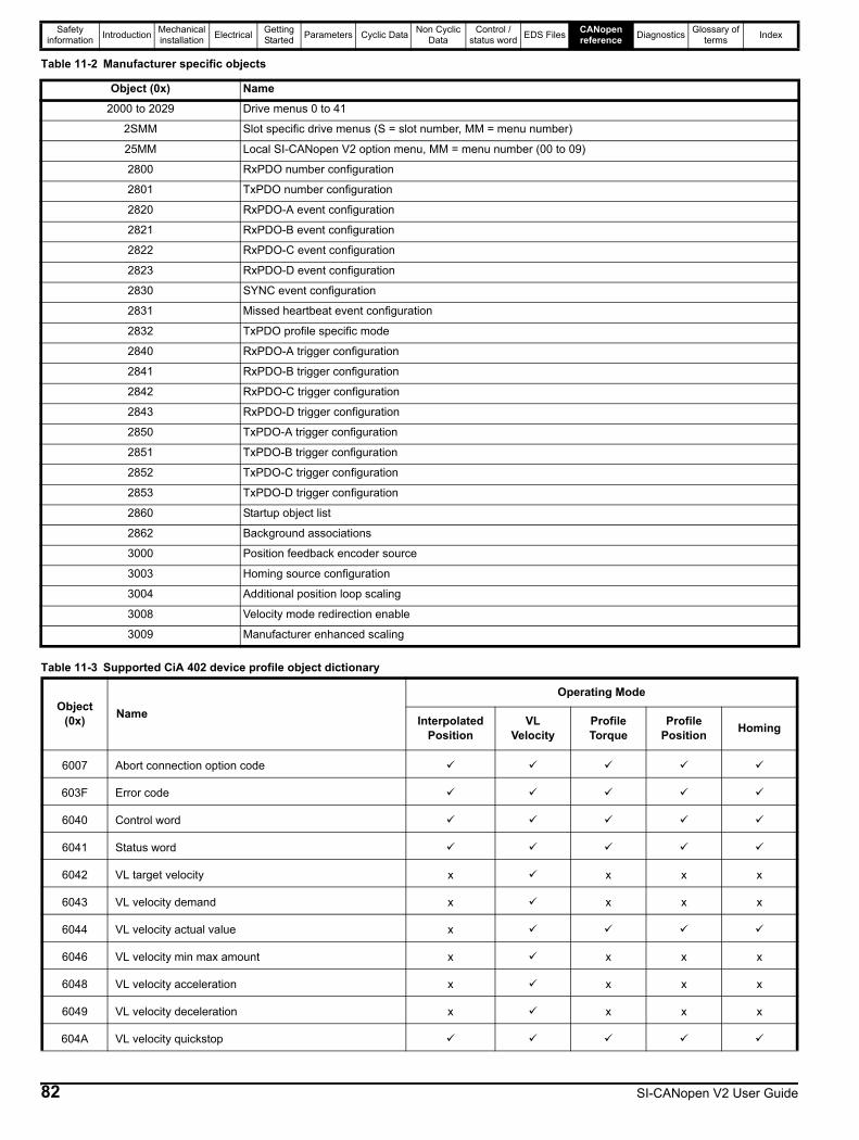
Safety information Introduction Mechanical
installation Electrical Getting Started Parameters Cyclic Data Non Cyclic
DataControl /
status word EDS Files CANopen reference Diagnostics Glossary of
terms Index
Table 11-2 Manufacturer specific objects
Table 11-3 Supported CiA 402 device profile object dictionary
Object (0x) Name2000 to 2029 Drive menus 0 to 41
2SMM Slot specific drive menus (S = slot number, MM = menu number)
25MM Local SI-CANopen V2 option menu, MM = menu number (00 to 09)
2800 RxPDO number configuration
2801 TxPDO number configuration
2820 RxPDO-A event configuration
2821 RxPDO-B event configuration
2822 RxPDO-C event configuration
2823 RxPDO-D event configuration
2830 SYNC event configuration
2831 Missed heartbeat event configuration
2832 TxPDO profile specific mode
2840 RxPDO-A trigger configuration
2841 RxPDO-B trigger configuration
2842 RxPDO-C trigger configuration
2843 RxPDO-D trigger configuration
2850 TxPDO-A trigger configuration
2851 TxPDO-B trigger configuration
2852 TxPDO-C trigger configuration
2853 TxPDO-D trigger configuration
2860 Startup object list
2862 Background associations
3000 Position feedback encoder source
3003 Homing source configuration
3004 Additional position loop scaling
3008 Velocity mode redirection enable
3009 Manufacturer enhanced scaling
Object(0x) Name
Operating Mode
Interpolated Position
VL Velocity
Profile Torque
Profile Position Homing
6007 Abort connection option code
603F Error code
6040 Control word
6041 Status word
6042 VL target velocity x x x x
6043 VL velocity demand x x x x
6044 VL velocity actual value x
6046 VL velocity min max amount x x x x
6048 VL velocity acceleration x x x x
6049 VL velocity deceleration x x x x
604A VL velocity quickstop
82 SI-CANopen V2 User Guide

Safety information Introduction Mechanical
installation Electrical Getting Started Parameters Cyclic Data Non Cyclic
DataControl /
status word EDS Files CANopen reference Diagnostics Glossary of
terms Index
604B VL setpoint factor x x x x
604C VL velocity dimension factor x x x x
604D VL pole number x x x x
605A Quick stop option code
605B Shutdown option code
605C Disable operation option code
605D Halt option code
605E Fault reaction option code
6060 Modes of operation
6061 Modes of operation display
6062 Position demand value x x x
6064 Position actual value
6065 Following error window x x x
6067 Position window x x x
6068 Position window time x x x x
606B Velocity demand value x x x
606C Velocity actual value
6071 Target torque x x x x
6073 Max current
6075 Motor rated current
6077 Torque actual value
6078 Current actual value
607A Target position x x x
607B Position range limit x x x x
607C Home offset x x x x
607D Software position limit x x x x
607F Max profile velocity x x x
6080 Max motor speed
6081 Profile velocity x x x x
6083 Profile acceleration x x x x
6084 Profile deceleration x x x x
6085 Quickstop deceleration x x
6086 Motion profile type x x x x
6087 Torque slope x x x x
Object(0x) Name
Operating Mode
Interpolated Position
VL Velocity
Profile Torque
Profile Position Homing
SI-CANopen V2 User Guide 83
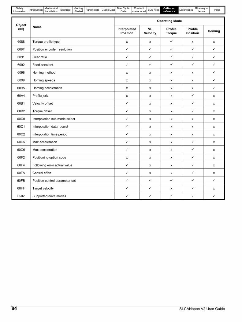
Safety information Introduction Mechanical
installation Electrical Getting Started Parameters Cyclic Data Non Cyclic
DataControl /
status word EDS Files CANopen reference Diagnostics Glossary of
terms Index
6088 Torque profile type x x x x
608F Position encoder resolution
6091 Gear ratio
6092 Feed constant
6098 Homing method x x x x
6099 Homing speeds x x x x
609A Homing acceleration x x x x
60A4 Profile jerk x x x x
60B1 Velocity offset x x x
60B2 Torque offset x x x
60C0 Interpolation sub mode select x x x x
60C1 Interpolation data record x x x x
60C2 Interpolation time period x x x x
60C5 Max acceleration x x x
60C6 Max deceleration x x x
60F2 Positioning option code x x x x
60F4 Following error actual value x x x
60FA Control effort x x x
60FB Position control parameter set
60FF Target velocity x x
6502 Supported drive modes
Object(0x) Name
Operating Mode
Interpolated Position
VL Velocity
Profile Torque
Profile Position Homing
84 SI-CANopen V2 User Guide
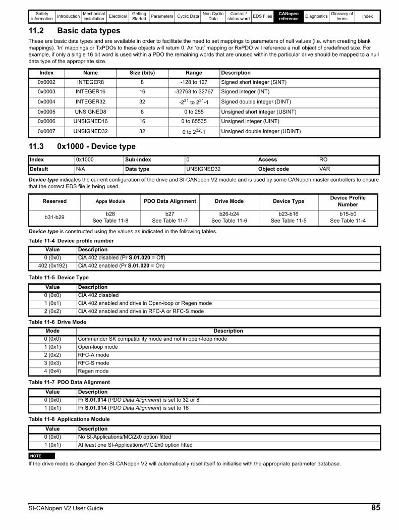
Safety information Introduction Mechanical
installation Electrical Getting Started Parameters Cyclic Data Non Cyclic
DataControl /
status word EDS Files CANopen reference Diagnostics Glossary of
terms Index
11.2 Basic data typesThese are basic data types and are available in order to facilitate the need to set mappings to parameters of null values (i.e. when creating blank mappings). ‘In’ mappings or TxPDOs to these objects will return 0. An ‘out’ mapping or RxPDO will reference a null object of predefined size. For example, if only a single 16 bit word is used within a PDO the remaining words that are unused within the particular drive should be mapped to a null data type of the appropriate size.
11.3 0x1000 - Device type
Device type indicates the current configuration of the drive and SI-CANopen V2 module and is used by some CANopen master controllers to ensure that the correct EDS file is being used.
Device type is constructed using the values as indicated in the following tables.
Table 11-5 Device Type
Table 11-7 PDO Data Alignment
Table 11-8 Applications Module
If the drive mode is changed then SI-CANopen V2 will automatically reset itself to initialise with the appropriate parameter database.
Index Name Size (bits) Range Description0x0002 INTEGER8 8 -128 to 127 Signed short integer (SINT)
0x0003 INTEGER16 16 -32768 to 32767 Signed integer (INT)
0x0004 INTEGER32 32 -231 to 231-1 Signed double integer (DINT)
0x0005 UNSIGNED8 8 0 to 255 Unsigned short integer (USINT)
0x0006 UNSIGNED16 16 0 to 65535 Unsigned integer (UINT)
0x0007 UNSIGNED32 32 0 to 232-1 Unsigned double integer (UDINT)
Index 0x1000 Sub-index 0 Access RO
Default N/A Data type UNSIGNED32 Object code VAR
Reserved Apps Module PDO Data Alignment Drive Mode Device Type Device Profile Number
b31-b29 b28See Table 11-8
b27See Table 11-7
b26-b24See Table 11-6
b23-b16See Table 11-5
b15-b0See Table 11-4
Table 11-4 Device profile numberValue Description0 (0x0) CiA 402 disabled (Pr S.01.020 = Off)
402 (0x192) CiA 402 enabled (Pr S.01.020 = On)
Value Description0 (0x0) CiA 402 disabled1 (0x1) CiA 402 enabled and drive in Open-loop or Regen mode2 (0x2) CiA 402 enabled and drive in RFC-A or RFC-S mode
Table 11-6 Drive ModeMode Description0 (0x0) Commander SK compatibility mode and not in open-loop mode1 (0x1) Open-loop mode2 (0x2) RFC-A mode3 (0x3) RFC-S mode4 (0x4) Regen mode
Value Description0 (0x0) Pr S.01.014 (PDO Data Alignment) is set to 32 or 81 (0x1) Pr S.01.014 (PDO Data Alignment) is set to 16
Value Description0 (0x0) No SI-Applications/MCi2x0 option fitted1 (0x1) At least one SI-Applications/MCi2x0 option fitted
NOTE
SI-CANopen V2 User Guide 85

Safety information Introduction Mechanical
installation Electrical Getting Started Parameters Cyclic Data Non Cyclic
DataControl /
status word EDS Files CANopen reference Diagnostics Glossary of
terms Index
11.4 0x1001 - Error register
The error register is used by SI-CANopen V2 to indicate that an error has occurred. If a bit is set to 1, the specified error has occurred. The error register is part of the emergency object, refer to section 11.39 0x1014 - Emergency object on page 124 for further details.
11.5 0x1002 - Manufacturer status register
The manufacturer status register is mapped directly to the status word (Pr 10.040) in the drive. See section 9.3 Status word on page 77 for more details about the drive status word.
11.6 0x1003 - Pre-defined error field
The pre-defined error field returns a 32-bit error code containing data from the last four emergency messages that were sent. If less than four emergency objects have been sent, the higher sub-indexes will not exist.
number of errors
Sub-index 0 is an unsigned8 data type which indicates the highest sub-index for the pre-defined error field. The rest of the array are unsigned32 data types.error field 1
Returns the last emergency object codes.error field 2
Returns the 2nd last emergency object codes.
error field 3
Returns the 3rd last emergency object codes.
Index 0x1001 Sub-index 0 Access RO
Default N/A Data type UNSIGNED8 Object code VAR
Bit Error0 Generic error
1 Current
2 Voltage
3 Temperature
4 Reserved
5 Reserved
6 Reserved
7 Manufacturer specific
Index 0x1002 Sub-index 0 Access RO
Default N/A Data type UNSIGNED32 Object code VAR
Index 0x1003
Object code ARRAY
Data type UNSIGNED32
Byte 3 Byte 2 Byte 1 Byte 0Drive trip code
(Pr 10.020)SI-CANopen V2
error code Emergency object error code
Index 0x1003 Sub-index 0 Access RO
Default 4 Data type UNSIGNED8 Object code VAR
Index 0x1003 Sub-index 1 Access RO
Default N/A Data type UNSIGNED32 Object code VAR
Index 0x1003 Sub-index 2 Access RO
Default N/A Data type UNSIGNED32 Object code VAR
Index 0x1003 Sub-index 3 Access RO
Default N/A Data type UNSIGNED32 Object code VAR
86 SI-CANopen V2 User Guide
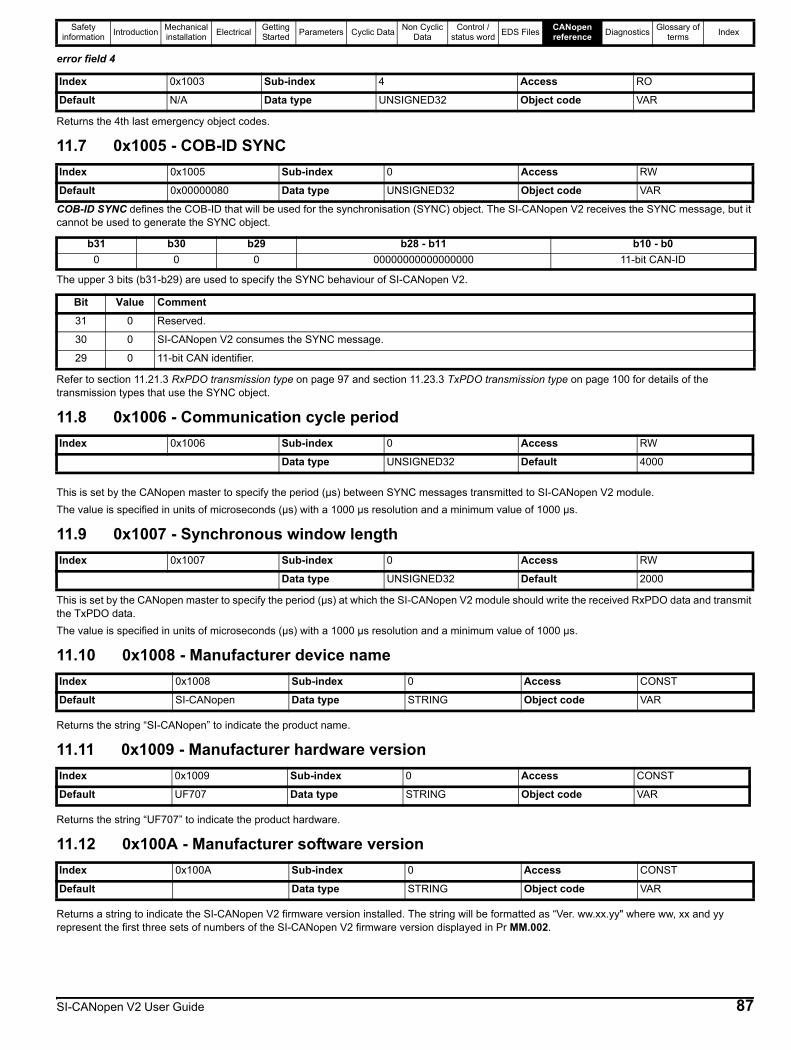
Safety information Introduction Mechanical
installation Electrical Getting Started Parameters Cyclic Data Non Cyclic
DataControl /
status word EDS Files CANopen reference Diagnostics Glossary of
terms Index
error field 4
Returns the 4th last emergency object codes.
11.7 0x1005 - COB-ID SYNC
COB-ID SYNC defines the COB-ID that will be used for the synchronisation (SYNC) object. The SI-CANopen V2 receives the SYNC message, but it cannot be used to generate the SYNC object.
The upper 3 bits (b31-b29) are used to specify the SYNC behaviour of SI-CANopen V2.
Refer to section 11.21.3 RxPDO transmission type on page 97 and section 11.23.3 TxPDO transmission type on page 100 for details of the transmission types that use the SYNC object.
11.8 0x1006 - Communication cycle period
This is set by the CANopen master to specify the period (µs) between SYNC messages transmitted to SI-CANopen V2 module.The value is specified in units of microseconds (µs) with a 1000 µs resolution and a minimum value of 1000 µs.
11.9 0x1007 - Synchronous window length
This is set by the CANopen master to specify the period (µs) at which the SI-CANopen V2 module should write the received RxPDO data and transmit the TxPDO data.The value is specified in units of microseconds (µs) with a 1000 µs resolution and a minimum value of 1000 µs.
11.10 0x1008 - Manufacturer device name
Returns the string “SI-CANopen” to indicate the product name.
11.11 0x1009 - Manufacturer hardware version
Returns the string “UF707” to indicate the product hardware.
11.12 0x100A - Manufacturer software version
Returns a string to indicate the SI-CANopen V2 firmware version installed. The string will be formatted as “Ver. ww.xx.yy" where ww, xx and yy represent the first three sets of numbers of the SI-CANopen V2 firmware version displayed in Pr MM.002.
Index 0x1003 Sub-index 4 Access RO
Default N/A Data type UNSIGNED32 Object code VAR
Index 0x1005 Sub-index 0 Access RW
Default 0x00000080 Data type UNSIGNED32 Object code VAR
b31 b30 b29 b28 - b11 b10 - b00 0 0 00000000000000000 11-bit CAN-ID
Bit Value Comment31 0 Reserved.
30 0 SI-CANopen V2 consumes the SYNC message.
29 0 11-bit CAN identifier.
Index 0x1006 Sub-index 0 Access RW
Data type UNSIGNED32 Default 4000
Index 0x1007 Sub-index 0 Access RW
Data type UNSIGNED32 Default 2000
Index 0x1008 Sub-index 0 Access CONST
Default SI-CANopen Data type STRING Object code VAR
Index 0x1009 Sub-index 0 Access CONST
Default UF707 Data type STRING Object code VAR
Index 0x100A Sub-index 0 Access CONST
Default Data type STRING Object code VAR
SI-CANopen V2 User Guide 87
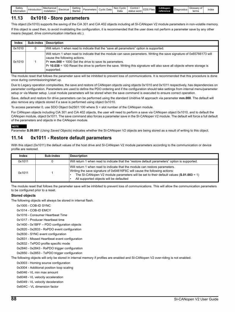
Safety information Introduction Mechanical
installation Electrical Getting Started Parameters Cyclic Data Non Cyclic
DataControl /
status word EDS Files CANopen reference Diagnostics Glossary of
terms Index
11.13 0x1010 - Store parametersThis object (0x1010) supports the saving of the CiA 301 and CiA 402 objects including all SI-CANopen V2 module parameters in non-volatile memory.If this object is used then, to avoid invalidating the configuration, it is recommended that the user does not perform a parameter save by any other means (keypad, drive communication interface etc.).
The module reset that follows the parameter save will be inhibited to prevent loss of communications. It is recommended that this procedure is done once during commissioning/start up.Due to Legacy operation complexities, the save and restore of CANopen objects using objects 0x1010 and 0x1011 respectively, has dependencies on parameter configuration. Parameters are used to define the PDO ordering and if the configuration should take settings from internal menu/parameter setup or via Master setup. Local module parameters will be stored when the save command is executed to ensure correct operation.Save, default and restore for drive parameters can be performed using the standard Unidrive M approach via parameter mm.000. The default will also remove any objects stored if a save is performed using object 0x1010.To access parameter 0, use SDO Object 0x2S01:100 where S = slot number of the CANopen module.For CANopen objects including CiA 301 and CiA 402 objects, the user will need to perform a save via CANopen object 0x1010, and to default the CANopen module, object 0x1011. The save command also forces a parameter save in the SI-CANopen V2 module. The default will force a full default of the parameters and objects in the CANopen module.
Parameter S.09.001 (Using Saved Objects) indicates whether the SI-CANopen V2 objects are being stored as a result of writing to this object.
11.14 0x1011 - Restore default parametersWith this object (0x1011) the default values of the host drive and SI-CANopen V2 module parameters according to the communication or device profile are restored.
The module reset that follows the parameter save will be inhibited to prevent loss of communications. This will allow the communication parameters to be configured prior to a reset.
Stored objectsThe following objects will always be stored in internal flash.
0x1005 - COB-ID SYNC0x1014 - COB-ID EMCY0x1016 - Consumer Heartbeat Time0x1017 - Producer Heartbeat time0x1400 - 0x1BFF – PDO configuration objects0x2820 - 0x2833 - RxPDO event configuration0x2830 - SYNC event configuration0x2831 - Missed Heartbeat event configuration0x2832 - TxPDO profile specific mode0x2840 - 0x2843 - RxPDO trigger configuration0x2850 - 0x2853 - TxPDO trigger configuration
The following objects will only be stored in internal memory if profiles are enabled and SI-CANopen V2 over-riding is not enabled.0x3003 - Homing source configuration0x3004 - Additional position loop scaling0x6046 - VL min max amount0x6048 - VL velocity acceleration0x6049 - VL velocity deceleration0x604C - VL dimension factor
Index Sub-index Description0x1010 0 Will return 1 when read to indicate that the “save all parameters” option is supported.
0x1010 1
Will return 1 when read to indicate that the module can save parameters. Writing the save signature of 0x65766173 will cause the following actions.Pr mm.000 = 1000 Set the drive to save its parameters.Pr 10.038 = 100 Reset the drive to perform the save. Writing this signature will also save all objects where storage is supported.
Index Sub-index Description0x1011 0 Will return 1 when read to indicate that the “restore default parameters” option is supported.
0x1011 1
Will return 1 when read to indicate that the module can restore parameters.Writing the save signature of 0x64616F6C will cause the following actions:• The SI-CANopen V2 module parameters will be set to their default values (S.01.003 = 1)• All supported objects will be defaulted
NOTE
88 SI-CANopen V2 User Guide
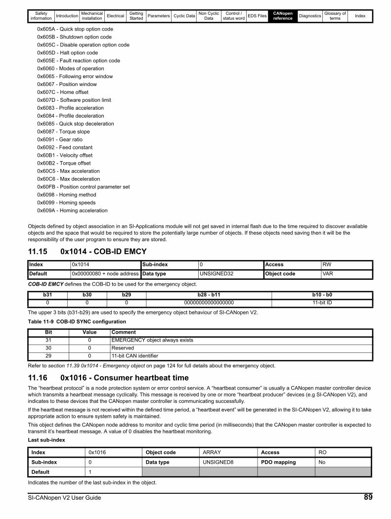
Safety information Introduction Mechanical
installation Electrical Getting Started Parameters Cyclic Data Non Cyclic
DataControl /
status word EDS Files CANopen reference Diagnostics Glossary of
terms Index
0x605A - Quick stop option code0x605B - Shutdown option code0x605C - Disable operation option code0x605D - Halt option code0x605E - Fault reaction option code0x6060 - Modes of operation0x6065 - Following error window0x6067 - Position window0x607C - Home offset0x607D - Software position limit0x6083 - Profile acceleration0x6084 - Profile deceleration0x6085 - Quick stop deceleration0x6087 - Torque slope0x6091 - Gear ratio0x6092 - Feed constant0x60B1 - Velocity offset0x60B2 - Torque offset0x60C5 - Max acceleration0x60C6 - Max deceleration0x60FB - Position control parameter set0x6098 - Homing method0x6099 - Homing speeds0x609A - Homing acceleration
Objects defined by object association in an SI-Applications module will not get saved in internal flash due to the time required to discover available objects and the space that would be required to store the potentially large number of objects. If these objects need saving then it will be the responsibility of the user program to ensure they are stored.
11.15 0x1014 - COB-ID EMCY
COB-ID EMCY defines the COB-ID to be used for the emergency object.
The upper 3 bits (b31-b29) are used to specify the emergency object behaviour of SI-CANopen V2.
Refer to section 11.39 0x1014 - Emergency object on page 124 for full details about the emergency object.
11.16 0x1016 - Consumer heartbeat timeThe “heartbeat protocol” is a node protection system or error control service. A “heartbeat consumer” is usually a CANopen master controller device which transmits a heartbeat message cyclically. This message is received by one or more “heartbeat producer” devices (e.g SI-CANopen V2), and indicates to these devices that the CANopen master controller is communicating successfully.If the heartbeat message is not received within the defined time period, a “heartbeat event” will be generated in the SI-CANopen V2, allowing it to take appropriate action to ensure system safety is maintained.This object defines the CANopen node address to monitor and cyclic time period (in milliseconds) that the CANopen master controller is expected to transmit it’s heartbeat message. A value of 0 disables the heartbeat monitoring.Last sub-index
Indicates the number of the last sub-index in the object.
Index 0x1014 Sub-index 0 Access RW
Default 0x00000080 + node address Data type UNSIGNED32 Object code VAR
b31 b30 b29 b28 - b11 b10 - b00 0 0 00000000000000000 11-bit ID
Table 11-9 COB-ID SYNC configuration
Bit Value Comment31 0 EMERGENCY object always exists30 0 Reserved29 0 11-bit CAN identifier
Index 0x1016 Object code ARRAY Access RO
Sub-index 0 Data type UNSIGNED8 PDO mapping No
Default 1
SI-CANopen V2 User Guide 89

Safety information Introduction Mechanical
installation Electrical Getting Started Parameters Cyclic Data Non Cyclic
DataControl /
status word EDS Files CANopen reference Diagnostics Glossary of
terms Index
Consumer heartbeat cycle time
Sub-index 1 specifies the CANopen master controller node address to monitor and the consumer heartbeat cycle time in milliseconds (ms).The consumer heartbeat cycle time must be greater than the corresponding producer heartbeat time configured on the SI-CANopen V2 module (object 0x1017).If the consumer heartbeat message is not received within the specified time then the SI-CANopen V2 module will return to the PRE-OPERATIONAL state and the configured object 0x2831 actions will be performed.If the specified node address is incorrect (i.e. not the CANopen master controller node address) or set to 0 then the configured object 0x2831 actions will not be performed.The following tables illustrates the bit significance of the consumer heartbeat cycle time value.
For example, if the CANopen master node address is 127 and a timeout value of 16 ms is required then sub-index 1 should be set to the value 0x007F0010.
11.17 0x1017 - Producer heartbeat time
The “heartbeat protocol” is a node protection system or error control service. A “heartbeat producer” is usually a CANopen slave device which transmits a heartbeat message cyclically. This message is received by one or more “heartbeat consumer” devices, usually the CANopen master controller, and indicates to the master controller that the slave device is communicating successfully.If the heartbeat message is not received within the defined time period, a “heartbeat event” will be generated in the master controller, allowing it to take appropriate action to ensure system safety is maintained.The producer heartbeat time defines the cyclic time period (in milliseconds) for SI-CANopen V2 to transmit the heartbeat message. A value of 0 disables the heartbeat message. The heartbeat message also includes the current NMT state of the SI-CANopen V2.
The SI-CANopen V2 will start transmitting the heartbeat message as soon as it is enabled. If the producer heartbeat time is set >0 at power up, SI-CANopen V2 will start transmitting the heartbeat message when the transition from BOOTUP to PRE-OPERATIONAL occurs. In this case, the boot-up message is regarded as the first heartbeat message.
11.18 0x1018 - Identity object
Identity object returns general information about the SI-CANopen V2.Number of entries
Returns the highest sub-index available for the identity object.Vendor ID
Index 0x1016 Object code VAR Access RW
Sub-index 1 Data type UNSIGNED32 PDO mapping No
Default 0 Units ms Maximum 8388607
b31 b30 b29 b28 b27 b26 b25 b24 b23 b22 b21 b20 b19 b18 b17 b16Reserved CANopen master node address
0
b15 b14 b13 b12 b11 b10 b9 b8 b7 b6 b5 b4 b3 b2 b1 b0Consumer Heartbeat Cycle Time (ms)
Index 0x1017 Sub-index 0 Access RW
Default 0 Data type UNSIGNED16 Object code VAR
Table 11-10 SI-CANopen V2 operating states
State Operating state0 BOOTUP4 STOPPED5 OPERATIONAL
127 PRE-OPERATIONAL
Index 0x1018
Object code RECORD
Data type UNSIGNED32
Index 0x1018 Sub-index 0 Access RO
Default 4 Data type UNSIGNED8
Index 0x1018 Sub-index 1 Access RO
Default 0xF9 Data type UNSIGNED32
90 SI-CANopen V2 User Guide
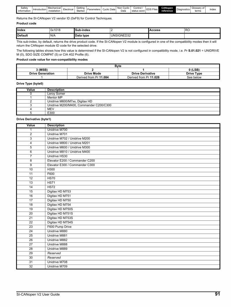
Safety information Introduction Mechanical
installation Electrical Getting Started Parameters Cyclic Data Non Cyclic
DataControl /
status word EDS Files CANopen reference Diagnostics Glossary of
terms Index
Returns the SI-CANopen V2 vendor ID (0xF9) for Control Techniques.Product code
This sub-index, by default, returns the drive product code. If the SI-CANopen V2 module is configured in one of the compatibility modes then it will return the CANopen module ID code for the selected drive.The following tables shows how this value is determined if the SI-CANopen V2 is not configured in compatibility mode, i.e. Pr S.01.021 = UNIDRIVE M (0), SDO SIZE COMPAT (5) or CIA 402 Profile (6).Product code value for non-compatibility modes
Drive Type (byte0)
Drive Derivative (byte1)
Index 0x1018 Sub-index 2 Access RO
Default N/A Data type UNSIGNED32
Byte3 (MSB) 2 1 0 (LSB)
Drive Generation Drive Mode Drive Derivative Drive Type1 Derived from Pr 11.084 Derived from Pr 11.028 See below
Value Description0 Leroy Somer1 Mentor MP2 Unidrive M600/M7xx, Digitax HD3 Unidrive M200/M400, Commander C200/C3004 MEV5 E300
Value Description1 Unidrive M7002 Unidrive M7013 Unidrive M702 / Unidrive M2004 Unidrive M800 / Unidrive M2015 Unidrive M600 / Unidrive M3006 Unidrive M810 / Unidrive M4007 Unidrive HS308 Elevator E200 / Commander C2009 Elevator E300 / Commander C300
10 H30011 F60012 HS7013 HS7114 HS7215 Digitax HD M75316 Digitax HD M75117 Digitax HD M75018 Digitax HD M75419 Digitax HD M750S20 Digitax HD M751S21 Digitax HD M753S22 Digitax HD M754S23 F600 Pump Drive24 Unidrive M88025 Unidrive M88126 Unidrive M88227 Unidrive M88828 Unidrive M88929 Reserved30 Reserved31 Unidrive M70832 Unidrive M709
SI-CANopen V2 User Guide 91
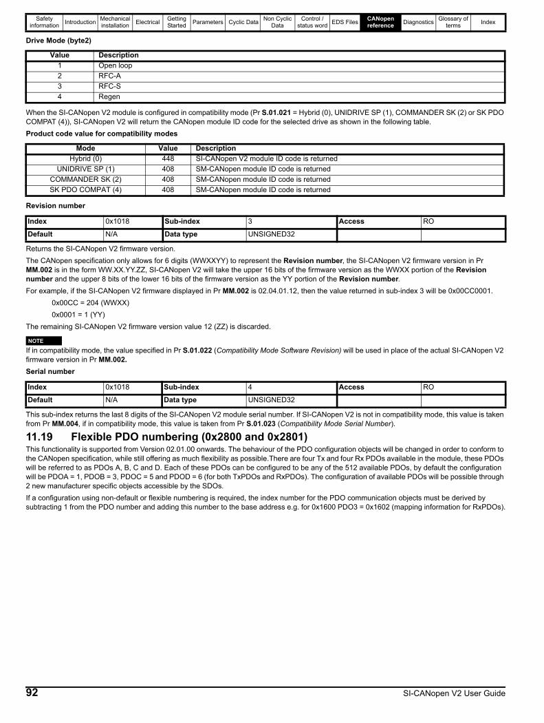
Safety information Introduction Mechanical
installation Electrical Getting Started Parameters Cyclic Data Non Cyclic
DataControl /
status word EDS Files CANopen reference Diagnostics Glossary of
terms Index
Drive Mode (byte2)
When the SI-CANopen V2 module is configured in compatibility mode (Pr S.01.021 = Hybrid (0), UNIDRIVE SP (1), COMMANDER SK (2) or SK PDO COMPAT (4)), SI-CANopen V2 will return the CANopen module ID code for the selected drive as shown in the following table.Product code value for compatibility modes
Revision number
Returns the SI-CANopen V2 firmware version.The CANopen specification only allows for 6 digits (WWXXYY) to represent the Revision number, the SI-CANopen V2 firmware version in Pr MM.002 is in the form WW.XX.YY.ZZ, SI-CANopen V2 will take the upper 16 bits of the firmware version as the WWXX portion of the Revision number and the upper 8 bits of the lower 16 bits of the firmware version as the YY portion of the Revision number.For example, if the SI-CANopen V2 firmware displayed in Pr MM.002 is 02.04.01.12, then the value returned in sub-index 3 will be 0x00CC0001.
0x00CC = 204 (WWXX) 0x0001 = 1 (YY)The remaining SI-CANopen V2 firmware version value 12 (ZZ) is discarded.
If in compatibility mode, the value specified in Pr S.01.022 (Compatibility Mode Software Revision) will be used in place of the actual SI-CANopen V2 firmware version in Pr MM.002.Serial number
This sub-index returns the last 8 digits of the SI-CANopen V2 module serial number. If SI-CANopen V2 is not in compatibility mode, this value is taken from Pr MM.004, if in compatibility mode, this value is taken from Pr S.01.023 (Compatibility Mode Serial Number).
11.19 Flexible PDO numbering (0x2800 and 0x2801)This functionality is supported from Version 02.01.00 onwards. The behaviour of the PDO configuration objects will be changed in order to conform to the CANopen specification, while still offering as much flexibility as possible.There are four Tx and four Rx PDOs available in the module, these PDOs will be referred to as PDOs A, B, C and D. Each of these PDOs can be configured to be any of the 512 available PDOs, by default the configuration will be PDOA = 1, PDOB = 3, PDOC = 5 and PDOD = 6 (for both TxPDOs and RxPDOs). The configuration of available PDOs will be possible through 2 new manufacturer specific objects accessible by the SDOs.If a configuration using non-default or flexible numbering is required, the index number for the PDO communication objects must be derived by subtracting 1 from the PDO number and adding this number to the base address e.g. for 0x1600 PDO3 = 0x1602 (mapping information for RxPDOs).
Value Description1 Open loop2 RFC-A3 RFC-S4 Regen
Mode Value DescriptionHybrid (0) 448 SI-CANopen V2 module ID code is returned
UNIDRIVE SP (1) 408 SM-CANopen module ID code is returnedCOMMANDER SK (2) 408 SM-CANopen module ID code is returnedSK PDO COMPAT (4) 408 SM-CANopen module ID code is returned
Index 0x1018 Sub-index 3 Access RO
Default N/A Data type UNSIGNED32
Index 0x1018 Sub-index 4 Access RO
Default N/A Data type UNSIGNED32
NOTE
92 SI-CANopen V2 User Guide
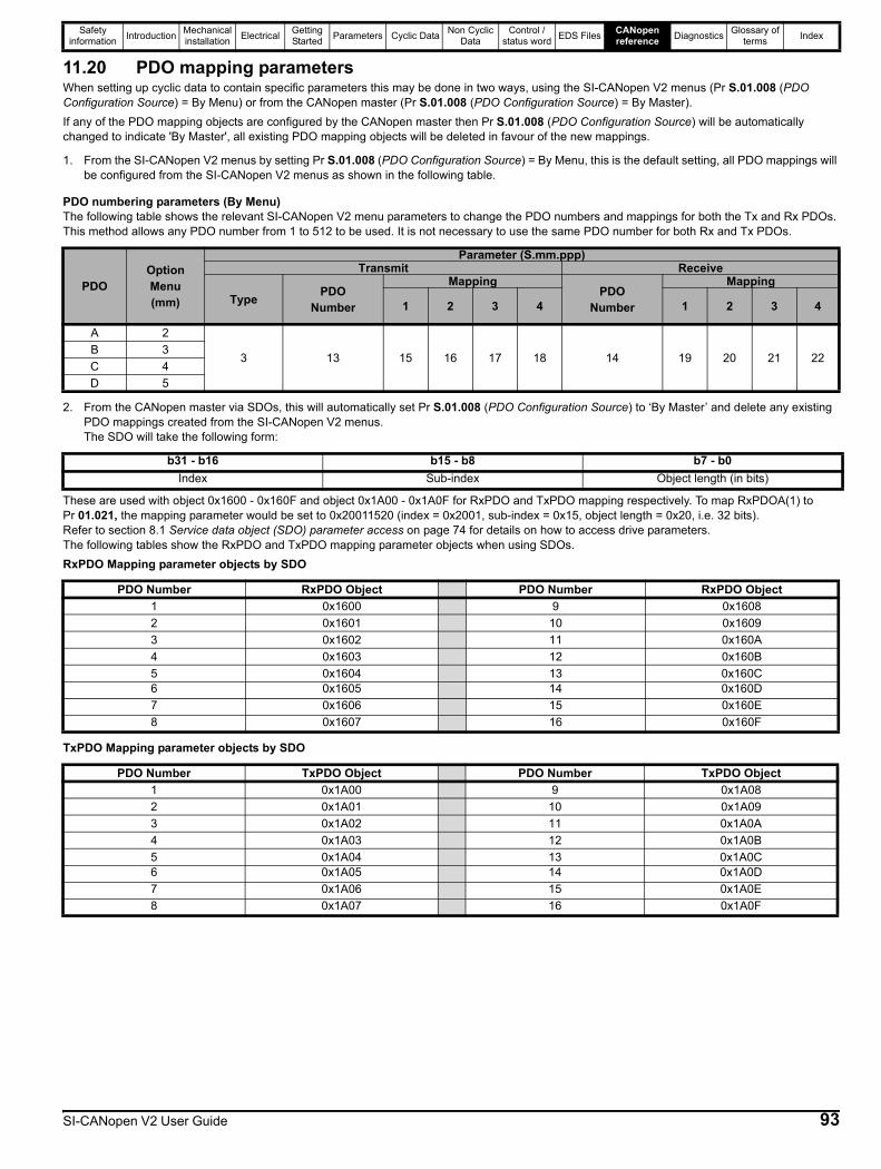
Safety information Introduction Mechanical
installation Electrical Getting Started Parameters Cyclic Data Non Cyclic
DataControl /
status word EDS Files CANopen reference Diagnostics Glossary of
terms Index
11.20 PDO mapping parametersWhen setting up cyclic data to contain specific parameters this may be done in two ways, using the SI-CANopen V2 menus (Pr S.01.008 (PDO Configuration Source) = By Menu) or from the CANopen master (Pr S.01.008 (PDO Configuration Source) = By Master). If any of the PDO mapping objects are configured by the CANopen master then Pr S.01.008 (PDO Configuration Source) will be automatically changed to indicate 'By Master', all existing PDO mapping objects will be deleted in favour of the new mappings.
1. From the SI-CANopen V2 menus by setting Pr S.01.008 (PDO Configuration Source) = By Menu, this is the default setting, all PDO mappings will be configured from the SI-CANopen V2 menus as shown in the following table.
PDO numbering parameters (By Menu)The following table shows the relevant SI-CANopen V2 menu parameters to change the PDO numbers and mappings for both the Tx and Rx PDOs. This method allows any PDO number from 1 to 512 to be used. It is not necessary to use the same PDO number for both Rx and Tx PDOs.
2. From the CANopen master via SDOs, this will automatically set Pr S.01.008 (PDO Configuration Source) to ‘By Master’ and delete any existing PDO mappings created from the SI-CANopen V2 menus. The SDO will take the following form:
These are used with object 0x1600 - 0x160F and object 0x1A00 - 0x1A0F for RxPDO and TxPDO mapping respectively. To map RxPDOA(1) to Pr 01.021, the mapping parameter would be set to 0x20011520 (index = 0x2001, sub-index = 0x15, object length = 0x20, i.e. 32 bits).Refer to section 8.1 Service data object (SDO) parameter access on page 74 for details on how to access drive parameters.The following tables show the RxPDO and TxPDO mapping parameter objects when using SDOs.RxPDO Mapping parameter objects by SDO
TxPDO Mapping parameter objects by SDO
PDOOptionMenu (mm)
Parameter (S.mm.ppp)Transmit Receive
Type PDONumber
MappingPDO
Number
Mapping
1 2 3 4 1 2 3 4
A 2
3 13 15 16 17 18 14 19 20 21 22B 3C 4D 5
b31 - b16 b15 - b8 b7 - b0Index Sub-index Object length (in bits)
PDO Number RxPDO Object PDO Number RxPDO Object1 0x1600 9 0x16082 0x1601 10 0x16093 0x1602 11 0x160A4 0x1603 12 0x160B5 0x1604 13 0x160C6 0x1605 14 0x160D7 0x1606 15 0x160E8 0x1607 16 0x160F
PDO Number TxPDO Object PDO Number TxPDO Object1 0x1A00 9 0x1A082 0x1A01 10 0x1A093 0x1A02 11 0x1A0A4 0x1A03 12 0x1A0B5 0x1A04 13 0x1A0C6 0x1A05 14 0x1A0D7 0x1A06 15 0x1A0E8 0x1A07 16 0x1A0F
SI-CANopen V2 User Guide 93
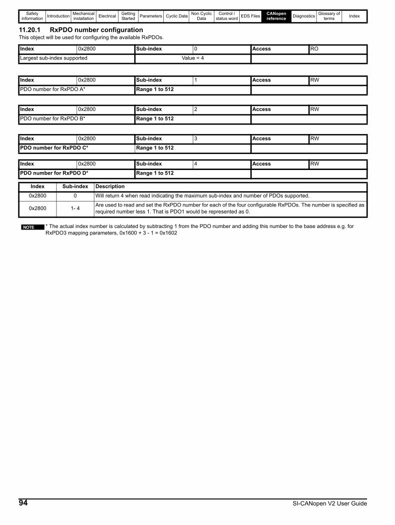
Safety information Introduction Mechanical
installation Electrical Getting Started Parameters Cyclic Data Non Cyclic
DataControl /
status word EDS Files CANopen reference Diagnostics Glossary of
terms Index
11.20.1 RxPDO number configurationThis object will be used for configuring the available RxPDOs.
Index 0x2800 Sub-index 0 Access RO
Largest sub-index supported Value = 4
Index 0x2800 Sub-index 1 Access RW
PDO number for RxPDO A* Range 1 to 512
Index 0x2800 Sub-index 2 Access RW
PDO number for RxPDO B* Range 1 to 512
Index 0x2800 Sub-index 3 Access RW
PDO number for RxPDO C* Range 1 to 512
Index 0x2800 Sub-index 4 Access RW
PDO number for RxPDO D* Range 1 to 512
Index Sub-index Description0x2800 0 Will return 4 when read indicating the maximum sub-index and number of PDOs supported.
0x2800 1- 4 Are used to read and set the RxPDO number for each of the four configurable RxPDOs. The number is specified as required number less 1. That is PDO1 would be represented as 0.
* The actual index number is calculated by subtracting 1 from the PDO number and adding this number to the base address e.g. for RxPDO3 mapping parameters, 0x1600 + 3 - 1 = 0x1602
NOTE
94 SI-CANopen V2 User Guide

Safety information Introduction Mechanical
installation Electrical Getting Started Parameters Cyclic Data Non Cyclic
DataControl /
status word EDS Files CANopen reference Diagnostics Glossary of
terms Index
11.20.2 TxPDO number configurationThis object will be used for configuring the available TxPDOs.
11.21 RxPDO communication parametersThis section contains the communication parameters for the receive PDOs.
SI-CANopen V2 supports a total of four RxPDOs. Each PDO has a base index assigned to it, with individual parameters for the PDO accessed using sub-indexes.
All RxPDO configuration parameters are dynamic (any changes made to these parameters will take effect immediately).
Index 0x2801 Sub-index 0 Access RO
Largest sub-index supported Value = 4
Index 0x2801 Sub-index 1 Access RW
PDO number for TxPDO A* Range 1 to 512
Index 0x2801 Sub-index 2 Access RW
PDO number for TxPDO B* Range 1 to 512
Index 0x2801 Sub-index 3 Access RW
PDO number for TxPDO C* Range 1 to 512
Index 0x2801 Sub-index 4 Access RW
PDO number for TxPDO D* Range 1 to 512
Index Sub-index Description0x2801 0 Will return 4 when read indicating the maximum sub-index and number of PDOs supported.
0x2801 1- 4 Are used to read and set the TxPDO number for each of the four configurable TxPDOs. The number is specified as required number less 1. That is PDO1 would be represented as 0.
* The actual index number is calculated by subtracting 1 from the PDO number and adding this number to the base address e.g. for TxPDO3 mapping parameters, 0x1A00 + 3 - 1 = 0x1A02
Index 0x1400-0x140F Sub-index 0 Access RO
Largest sub-index supported Size
Index 0x1400-0x140F Sub-index 1 Access RO
COB-ID used by PDO Size
Index 0x1400-0x140F Sub-index 2 Access RW
Transmission type Size
Index 0x1400-0x140F Sub-index 3 Access RW
Inhibit time (not used for RxPDO) Size
Index 0x1400-0x140F Sub-index 5 Access RW
Event timer Size
NOTE
Table 11-11 Supported RxPDOs
RxPDO IndexA 0x1400-0x140FB 0x1400-0x140FC 0x1400-0x140FD 0x1400-0x140F
SI-CANopen V2 User Guide 95
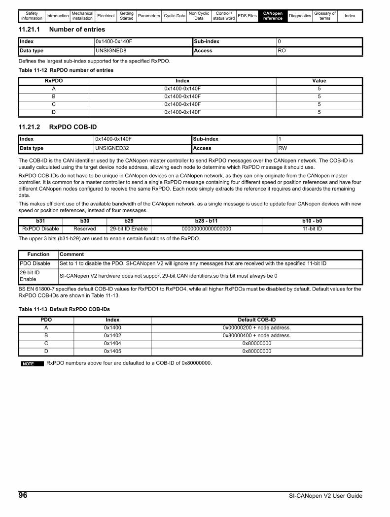
Safety information Introduction Mechanical
installation Electrical Getting Started Parameters Cyclic Data Non Cyclic
DataControl /
status word EDS Files CANopen reference Diagnostics Glossary of
terms Index
11.21.1 Number of entries
Defines the largest sub-index supported for the specified RxPDO.
11.21.2 RxPDO COB-ID
The COB-ID is the CAN identifier used by the CANopen master controller to send RxPDO messages over the CANopen network. The COB-ID is usually calculated using the target device node address, allowing each node to determine which RxPDO message it should use.RxPDO COB-IDs do not have to be unique in CANopen devices on a CANopen network, as they can only originate from the CANopen master controller. It is common for a master controller to send a single RxPDO message containing four different speed or position references and have four different CANopen nodes configured to receive the same RxPDO. Each node simply extracts the reference it requires and discards the remaining data.This makes efficient use of the available bandwidth of the CANopen network, as a single message is used to update four CANopen devices with new speed or position references, instead of four messages.
The upper 3 bits (b31-b29) are used to enable certain functions of the RxPDO.
BS EN 61800-7 specifies default COB-ID values for RxPDO1 to RxPDO4, while all higher RxPDOs must be disabled by default. Default values for the RxPDO COB-IDs are shown in Table 11-13.
Index 0x1400-0x140F Sub-index 0
Data type UNSIGNED8 Access RO
Table 11-12 RxPDO number of entries
RxPDO Index ValueA 0x1400-0x140F 5B 0x1400-0x140F 5C 0x1400-0x140F 5D 0x1400-0x140F 5
Index 0x1400-0x140F Sub-index 1
Data type UNSIGNED32 Access RW
b31 b30 b29 b28 - b11 b10 - b0RxPDO Disable Reserved 29-bit ID Enable 00000000000000000 11-bit ID
Function CommentPDO Disable Set to 1 to disable the PDO. SI-CANopen V2 will ignore any messages that are received with the specified 11-bit ID
29-bit ID Enable SI-CANopen V2 hardware does not support 29-bit CAN identifiers.so this bit must always be 0
Table 11-13 Default RxPDO COB-IDs
PDO Index Default COB-IDA 0x1400 0x00000200 + node address.B 0x1402 0x80000400 + node address.C 0x1404 0x80000000 D 0x1405 0x80000000
RxPDO numbers above four are defaulted to a COB-ID of 0x80000000.NOTE
96 SI-CANopen V2 User Guide
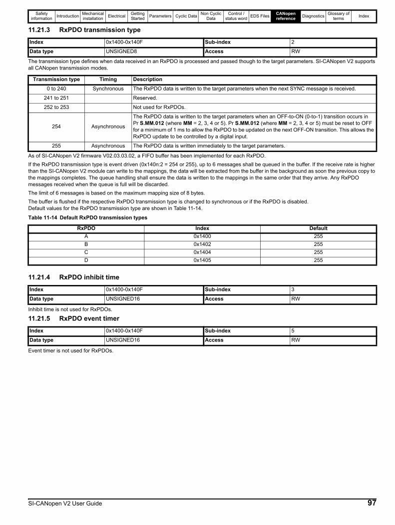
Safety information Introduction Mechanical
installation Electrical Getting Started Parameters Cyclic Data Non Cyclic
DataControl /
status word EDS Files CANopen reference Diagnostics Glossary of
terms Index
11.21.3 RxPDO transmission type
The transmission type defines when data received in an RxPDO is processed and passed though to the target parameters. SI-CANopen V2 supports all CANopen transmission modes.
As of SI-CANopen V2 firmware V02.03.03.02, a FIFO buffer has been implemented for each RxPDO.If the RxPDO transmission type is event driven (0x140n:2 = 254 or 255), up to 6 messages shall be queued in the buffer. If the receive rate is higher than the SI-CANopen V2 module can write to the mappings, the data will be extracted from the buffer in the background as soon the previous copy to the mappings completes. The queue handling shall ensure the data is written to the mappings in the same order that they arrive. Any RxPDO messages received when the queue is full will be discarded.The limit of 6 messages is based on the maximum mapping size of 8 bytes.The buffer is flushed if the respective RxPDO transmission type is changed to synchronous or if the RxPDO is disabled.Default values for the RxPDO transmission type are shown in Table 11-14.
11.21.4 RxPDO inhibit time
Inhibit time is not used for RxPDOs.
11.21.5 RxPDO event timer
Event timer is not used for RxPDOs.
Index 0x1400-0x140F Sub-index 2
Data type UNSIGNED8 Access RW
Transmission type Timing Description0 to 240 Synchronous The RxPDO data is written to the target parameters when the next SYNC message is received.
241 to 251 Reserved.
252 to 253 Not used for RxPDOs.
254 Asynchronous
The RxPDO data is written to the target parameters when an OFF-to-ON (0-to-1) transition occurs in Pr S.MM.012 (where MM = 2, 3, 4 or 5). Pr S.MM.012 (where MM = 2, 3, 4 or 5) must be reset to OFF for a minimum of 1 ms to allow the RxPDO to be updated on the next OFF-ON transition. This allows the RxPDO update to be controlled by a digital input.
255 Asynchronous The RxPDO data is written immediately to the target parameters.
Table 11-14 Default RxPDO transmission types
RxPDO Index DefaultA 0x1400 255B 0x1402 255C 0x1404 255D 0x1405 255
Index 0x1400-0x140F Sub-index 3
Data type UNSIGNED16 Access RW
Index 0x1400-0x140F Sub-index 5
Data type UNSIGNED16 Access RW
SI-CANopen V2 User Guide 97
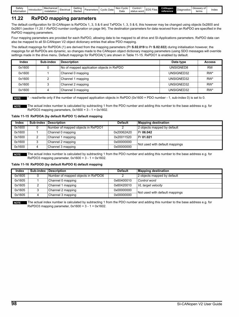
Safety information Introduction Mechanical
installation Electrical Getting Started Parameters Cyclic Data Non Cyclic
DataControl /
status word EDS Files CANopen reference Diagnostics Glossary of
terms Index
11.22 RxPDO mapping parametersThe default configuration for SI-CANopen is RxPDOs 1, 3, 5 & 6 and TxPDOs 1, 3, 5 & 6, this however may be changed using objects 0x2800 and 0x2801 (section 11.20.1 RxPDO number configuration on page 94). The destination parameters for data received from an RxPDO are specified in the RxPDO mapping parameters.Four mapping parameters are provided for each RxPDO, allowing data to be mapped to all drive and SI-Applications parameters. RxPDO data can also be mapped to all SI-CANopen V2 object dictionary entries that allow PDO mapping.The default mappings for RxPDOA (1) are derived from the mapping parameters (Pr S.02.019 to Pr S.02.022) during initialisation however, the mappings for all RxPDOs are dynamic, so changes made to the CANopen object dictionary mapping parameters (using SDO messages will override settings made in the drive menu. Default mappings for RxPDOA(1) are shown in Table 11-15. RxPDO1 is enabled by default.
Index Sub-index Description Data type Access0x1600 0 No of mapped application objects in RxPDO UNSIGNED8 RW
0x1600 1 Channel 0 mapping UNSIGNED32 RW*
0x1600 2 Channel 1 mapping UNSIGNED32 RW*
0x1600 3 Channel 2 mapping UNSIGNED32 RW*
0x1600 4 Channel 3 mapping UNSIGNED32 RW*
* - read/write only if the number of mapped application objects in RxPDO (0x1600 + PDO number - 1, sub-index 0) is set to 0.
The actual index number is calculated by subtracting 1 from the PDO number and adding this number to the base address e.g. for RxPDO3 mapping parameters, 0x1600 + 3 - 1 = 0x1602.
Table 11-15 RxPDOA (by default RxPDO 1) default mapping
Index Sub-index Description Default Mapping destination0x1600 0 Number of mapped objects in RxPDO1 2 2 objects mapped by default0x1600 1 Channel 0 mapping 0x20062A20 Pr 06.0420x1600 2 Channel 1 mapping 0x20011520 Pr 01.0210x1600 3 Channel 2 mapping 0x00000000
Not used with default mappings0x1600 4 Channel 3 mapping 0x00000000
The actual index number is calculated by subtracting 1 from the PDO number and adding this number to the base address e.g. for RxPDO3 mapping parameter, 0x1600 + 3 - 1 = 0x1602.
Table 11-16 RxPDOD (by default RxPDO 6) default mapping
Index Sub-index Description Default Mapping destination0x1605 0 Number of mapped objects in RxPDO6 2 2 objects mapped by default0x1605 1 Channel 0 mapping 0x60400010 Control word0x1605 2 Channel 1 mapping 0x60420010 VL target velocity0x1605 3 Channel 2 mapping 0x00000000
Not used with default mappings0x1605 4 Channel 3 mapping 0x00000000
The actual index number is calculated by subtracting 1 from the PDO number and adding this number to the base address e.g. for RxPDO3 mapping parameter, 0x1600 + 3 - 1 = 0x1602.
NOTE
NOTE
NOTE
NOTE
98 SI-CANopen V2 User Guide
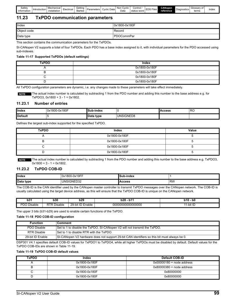
Safety information Introduction Mechanical
installation Electrical Getting Started Parameters Cyclic Data Non Cyclic
DataControl /
status word EDS Files CANopen reference Diagnostics Glossary of
terms Index
11.23 TxPDO communication parameters
This section contains the communication parameters for the TxPDOs. SI-CANopen V2 supports a total of four TxPDOs. Each PDO has a base index assigned to it, with individual parameters for the PDO accessed using sub-indexes.
All TxPDO configuration parameters are dynamic, i.e. any changes made to these parameters will take effect immediately.
11.23.1 Number of entries
Defines the largest sub-index supported for the specified TxPDO.
11.23.2 TxPDO COB-ID
The COB-ID is the CAN identifier used by the CANopen master controller to transmit TxPDO messages over the CANopen network. The COB-ID is usually calculated using the target device address, as this will ensure that the TxPDO COB-ID is unique on the CANopen network.
The upper 3 bits (b31-b29) are used to enable certain functions of the TxPDO.
DSP301 V4.1 specifies default COB-ID values for TxPDO1 to TxPDO4, while all higher TxPDOs must be disabled by default. Default values for the TxPDO COB-IDs are shown in Table 11-19.
Index 0x1800-0x180F
Object code Record
Data type PDOCommPar
Table 11-17 Supported TxPDOs (default settings)
TxPDO IndexA 0x1800-0x180FB 0x1800-0x180FC 0x1800-0x180FD 0x1800-0x180F
The actual index number is calculated by subtracting 1 from the PDO number and adding this number to the base address e.g. for TxPDO3, 0x1800 + 3 - 1 = 0x1802.
Index 0x1800-0x180F Sub-index 0 Access RO
Default 5 Data type UNSIGNED8
TxPDO Index ValueA 0x1800-0x180F 5
B 0x1800-0x180F 5
C 0x1800-0x180F 5
D 0x1800-0x180F 5
The actual index number is calculated by subtracting 1 from the PDO number and adding this number to the base address e.g. TxPDO3, 0x1800 + 3 - 1 = 0x1802.
NOTE
NOTE
Index 0x1800-0x19FF Sub-index 1
Data type UNSIGNED32 Access RW
b31 b30 b29 b28 - b11 b10 - b0PDO Disable RTR Disable 29-bit ID Enable 00000000000000000 11-bit ID
Table 11-18 PDO COB-ID configuration
Function CommentPDO Disable Set to 1 to disable the TxPDO. SI-CANopen V2 will not transmit the TxPDO.RTR Disable Set to 1 to disable RTR with the TxPDO.
29-bit ID Enable SI-CANopen V2 hardware does not support 29-bit CAN identifiers so this bit must always be 0.
Table 11-19 TxPDO COB-ID default values
TxPDO Index Default COB-IDA 0x1800-0x180F 0x00000180 + node addressB 0x1800-0x180F 0x80000380 + node addressC 0x1800-0x180F 0x80000000D 0x1800-0x180F 0x80000000
SI-CANopen V2 User Guide 99
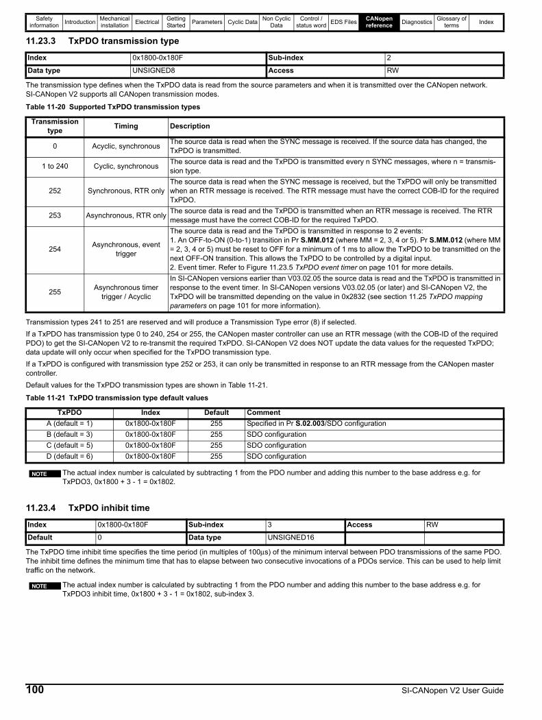
Safety information Introduction Mechanical
installation Electrical Getting Started Parameters Cyclic Data Non Cyclic
DataControl /
status word EDS Files CANopen reference Diagnostics Glossary of
terms Index
11.23.3 TxPDO transmission type
The transmission type defines when the TxPDO data is read from the source parameters and when it is transmitted over the CANopen network. SI-CANopen V2 supports all CANopen transmission modes.
Transmission types 241 to 251 are reserved and will produce a Transmission Type error (8) if selected.If a TxPDO has transmission type 0 to 240, 254 or 255, the CANopen master controller can use an RTR message (with the COB-ID of the required PDO) to get the SI-CANopen V2 to re-transmit the required TxPDO. SI-CANopen V2 does NOT update the data values for the requested TxPDO; data update will only occur when specified for the TxPDO transmission type.If a TxPDO is configured with transmission type 252 or 253, it can only be transmitted in response to an RTR message from the CANopen master controller.Default values for the TxPDO transmission types are shown in Table 11-21.
11.23.4 TxPDO inhibit time
The TxPDO time inhibit time specifies the time period (in multiples of 100μs) of the minimum interval between PDO transmissions of the same PDO. The inhibit time defines the minimum time that has to elapse between two consecutive invocations of a PDOs service. This can be used to help limit traffic on the network.
Index 0x1800-0x180F Sub-index 2
Data type UNSIGNED8 Access RW
Table 11-20 Supported TxPDO transmission types
Transmission type Timing Description
0 Acyclic, synchronous The source data is read when the SYNC message is received. If the source data has changed, the TxPDO is transmitted.
1 to 240 Cyclic, synchronous The source data is read and the TxPDO is transmitted every n SYNC messages, where n = transmis-sion type.
252 Synchronous, RTR onlyThe source data is read when the SYNC message is received, but the TxPDO will only be transmitted when an RTR message is received. The RTR message must have the correct COB-ID for the required TxPDO.
253 Asynchronous, RTR only The source data is read and the TxPDO is transmitted when an RTR message is received. The RTR message must have the correct COB-ID for the required TxPDO.
254 Asynchronous, event trigger
The source data is read and the TxPDO is transmitted in response to 2 events:1. An OFF-to-ON (0-to-1) transition in Pr S.MM.012 (where MM = 2, 3, 4 or 5). Pr S.MM.012 (where MM = 2, 3, 4 or 5) must be reset to OFF for a minimum of 1 ms to allow the TxPDO to be transmitted on the next OFF-ON transition. This allows the TxPDO to be controlled by a digital input.2. Event timer. Refer to Figure 11.23.5 TxPDO event timer on page 101 for more details.
255 Asynchronous timer trigger / Acyclic
In SI-CANopen versions earlier than V03.02.05 the source data is read and the TxPDO is transmitted in response to the event timer. In SI-CANopen versions V03.02.05 (or later) and SI-CANopen V2, the TxPDO will be transmitted depending on the value in 0x2832 (see section 11.25 TxPDO mapping parameters on page 101 for more information).
Table 11-21 TxPDO transmission type default values
TxPDO Index Default CommentA (default = 1) 0x1800-0x180F 255 Specified in Pr S.02.003/SDO configurationB (default = 3) 0x1800-0x180F 255 SDO configurationC (default = 5) 0x1800-0x180F 255 SDO configurationD (default = 6) 0x1800-0x180F 255 SDO configuration
The actual index number is calculated by subtracting 1 from the PDO number and adding this number to the base address e.g. for TxPDO3, 0x1800 + 3 - 1 = 0x1802.
Index 0x1800-0x180F Sub-index 3 Access RW
Default 0 Data type UNSIGNED16
The actual index number is calculated by subtracting 1 from the PDO number and adding this number to the base address e.g. for TxPDO3 inhibit time, 0x1800 + 3 - 1 = 0x1802, sub-index 3.
NOTE
NOTE
100 SI-CANopen V2 User Guide

Safety information Introduction Mechanical
installation Electrical Getting Started Parameters Cyclic Data Non Cyclic
DataControl /
status word EDS Files CANopen reference Diagnostics Glossary of
terms Index
11.23.5 TxPDO event timer
The TxPDO event timer specifies the time period (in ms) between transmission of TxPDOs with transmission type 254 or 255 (see section 11-21 TxPDO transmission type default values on page 100). Set the TxPDO event timer to 0 to disable the event timer.
11.24 TxPDO profile specific mode
If a TxPDO is configured with a transmission type of 255 the TxPDO will be transmitted dependant on the values detailed in Table 11-22 below. Table 11-22 Supported TxPDO Transmission type 255 modes
11.25 TxPDO mapping parametersThe source parameters for data transmitted on a TxPDO are specified in the TxPDO mapping parameters. Four mapping parameters are provided for each TxPDO, allowing data to be mapped to all drive and SI-Applications parameters. TxPDO data can also be mapped to all SI-CANopen V2 object dictionary entries that allow PDO mapping.The default mappings for TxPDOA (1) are derived from the mapping parameters (Pr S.02.015 to Pr S.02.018) during initialisation and configured via the menu, therefore changes made via these parameters will require a reset in order to take effect. However, the mappings for all four TxPDOs can be changed via the appropriate CANopen object dictionary mapping objects (using SDO messages), changes made via this method will take effect immediately.
The default mappings for TxPDO1 are shown in Table 11-24. TxPDO1 is enabled by default. The default configuration for SI-CANopen is RxPDOs 1, 3, 5 & 6 and TxPDOs 1, 3, 5 & 6, this however may be changed using objects 0x2800 and 0x2801 (section 11.20.1 RxPDO number configuration on page 94). The source parameters for data transmitted in a TxPDO are specified in the TxPDO mapping parameters.Four mapping parameters are provided for each TxPDO, allowing data to be mapped to all drive and SI-Applications parameters. TxPDO data can also be mapped to all SI-CANopen V2 object dictionary entries that allow PDO mapping.
Index 0x1800-0x180F Sub-index 5 Access RW
Default 0 Data type UNSIGNED16
The actual index number is calculated by subtracting 1 from the PDO number and adding this number to the base address e.g. for TxPDO3 event timer, 0x1800 + 3 - 1 = 0x1802, sub-index 5.
NOTE
Index 0x2832 Sub-index 0 Access RW
TxPDO profile specific mode Data type BYTE Default 0
Value Mode Description0 Timed PDO will be transmitted each time the event timer expires.
1 Change OR Timed PDO will be transmitted when data has changed unless an event timer is specified.
2 Change AND Timed PDO will be transmitted when mapped data values change as well as each time the event timer expires.
The actual index number is calculated by subtracting 1 from the PDO number and adding this number to the base address e.g. for TxPDO3, 0x1800 + 3 - 1 = 0x1802.
The SI-CANopen V2 will NOT update the drive mapping parameters if the CANopen object dictionary mapping parameters are changed after the SI-CANopen V2 has initialised. This means that the SI-CANopen V2 will revert to the drive parameter-defined mappings during the next initialisation.
Table 11-23 TxPDO mapping parameters
Index Sub-index Description Data type Access0x1A00-0x1A0F 0 Number of mapped objects in TxPDO UNSIGNED8 RW0x1A00-0x1A0F 1 Channel 0 mapping UNSIGNED32 RW*0x1A00-0x1A0F 2 Channel 1 mapping UNSIGNED32 RW*0x1A00-0x1A0F 3 Channel 2 mapping UNSIGNED32 RW*0x1A00-0x1A0F 4 Channel 3 mapping UNSIGNED32 RW*
* - read/write only if the number of mapped application objects in TxPDO 0x1A00 + PDO number - 1, sub-index 0 is set to 0.
The actual index number is calculated by subtracting 1 from the PDO number and adding this number to the base address e.g. for TxPDO3, 0x1A00 + 3 - 1 = 0x1A02.
Table 11-24 TxPDOA (by default TxPDO 1)
Index Sub-index Description Default Mapping destination0x1A00 0 Number of entries 2 N/A0x1A00 1 Channel 0 mapping 0x200A2820 Pr 10.0400x1A00 2 Channel 1 mapping 0x20020120 Pr 02.0010x1A00 3 Channel 2 mapping 0x00000000
Not used with default mappings0x1A00 4 Channel 3 mapping 0x00000000
NOTE
NOTE
NOTE
NOTE
SI-CANopen V2 User Guide 101
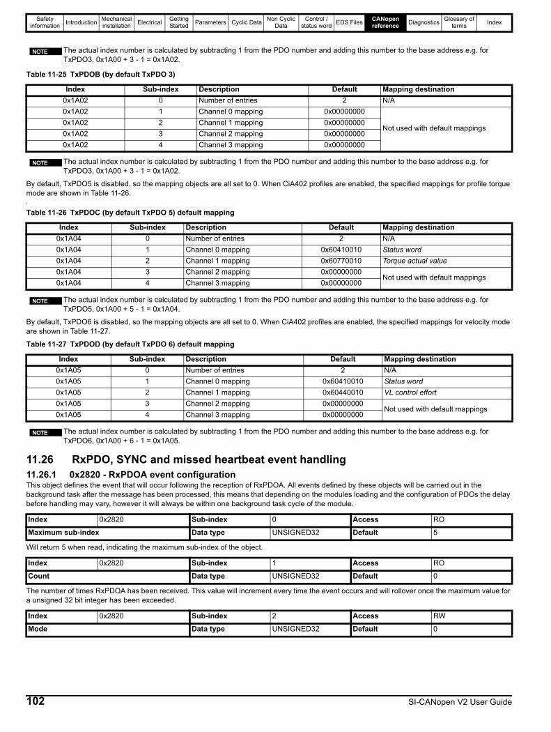
Safety information Introduction Mechanical
installation Electrical Getting Started Parameters Cyclic Data Non Cyclic
DataControl /
status word EDS Files CANopen reference Diagnostics Glossary of
terms Index
By default, TxPDO5 is disabled, so the mapping objects are all set to 0. When CiA402 profiles are enabled, the specified mappings for profile torque mode are shown in Table 11-26.q
By default, TxPDO6 is disabled, so the mapping objects are all set to 0. When CiA402 profiles are enabled, the specified mappings for velocity mode are shown in Table 11-27.
11.26 RxPDO, SYNC and missed heartbeat event handling11.26.1 0x2820 - RxPDOA event configurationThis object defines the event that will occur following the reception of RxPDOA. All events defined by these objects will be carried out in the background task after the message has been processed, this means that depending on the modules loading and the configuration of PDOs the delay before handling may vary, however it will always be within one background task cycle of the module.
Will return 5 when read, indicating the maximum sub-index of the object.
The number of times RxPDOA has been received. This value will increment every time the event occurs and will rollover once the maximum value for a unsigned 32 bit integer has been exceeded.
The actual index number is calculated by subtracting 1 from the PDO number and adding this number to the base address e.g. for TxPDO3, 0x1A00 + 3 - 1 = 0x1A02.
Table 11-25 TxPDOB (by default TxPDO 3)
Index Sub-index Description Default Mapping destination0x1A02 0 Number of entries 2 N/A0x1A02 1 Channel 0 mapping 0x00000000
Not used with default mappings0x1A02 2 Channel 1 mapping 0x000000000x1A02 3 Channel 2 mapping 0x000000000x1A02 4 Channel 3 mapping 0x00000000
The actual index number is calculated by subtracting 1 from the PDO number and adding this number to the base address e.g. for TxPDO3, 0x1A00 + 3 - 1 = 0x1A02.
NOTE
NOTE
Table 11-26 TxPDOC (by default TxPDO 5) default mapping
Index Sub-index Description Default Mapping destination0x1A04 0 Number of entries 2 N/A0x1A04 1 Channel 0 mapping 0x60410010 Status word0x1A04 2 Channel 1 mapping 0x60770010 Torque actual value0x1A04 3 Channel 2 mapping 0x00000000
Not used with default mappings0x1A04 4 Channel 3 mapping 0x00000000
The actual index number is calculated by subtracting 1 from the PDO number and adding this number to the base address e.g. for TxPDO5, 0x1A00 + 5 - 1 = 0x1A04.
Table 11-27 TxPDOD (by default TxPDO 6) default mapping
Index Sub-index Description Default Mapping destination0x1A05 0 Number of entries 2 N/A0x1A05 1 Channel 0 mapping 0x60410010 Status word0x1A05 2 Channel 1 mapping 0x60440010 VL control effort0x1A05 3 Channel 2 mapping 0x00000000
Not used with default mappings0x1A05 4 Channel 3 mapping 0x00000000
The actual index number is calculated by subtracting 1 from the PDO number and adding this number to the base address e.g. for TxPDO6, 0x1A00 + 6 - 1 = 0x1A05.
Index 0x2820 Sub-index 0 Access RO
Maximum sub-index Data type UNSIGNED32 Default 5
Index 0x2820 Sub-index 1 Access RO
Count Data type UNSIGNED32 Default 0
Index 0x2820 Sub-index 2 Access RW
Mode Data type UNSIGNED32 Default 0
NOTE
NOTE
102 SI-CANopen V2 User Guide
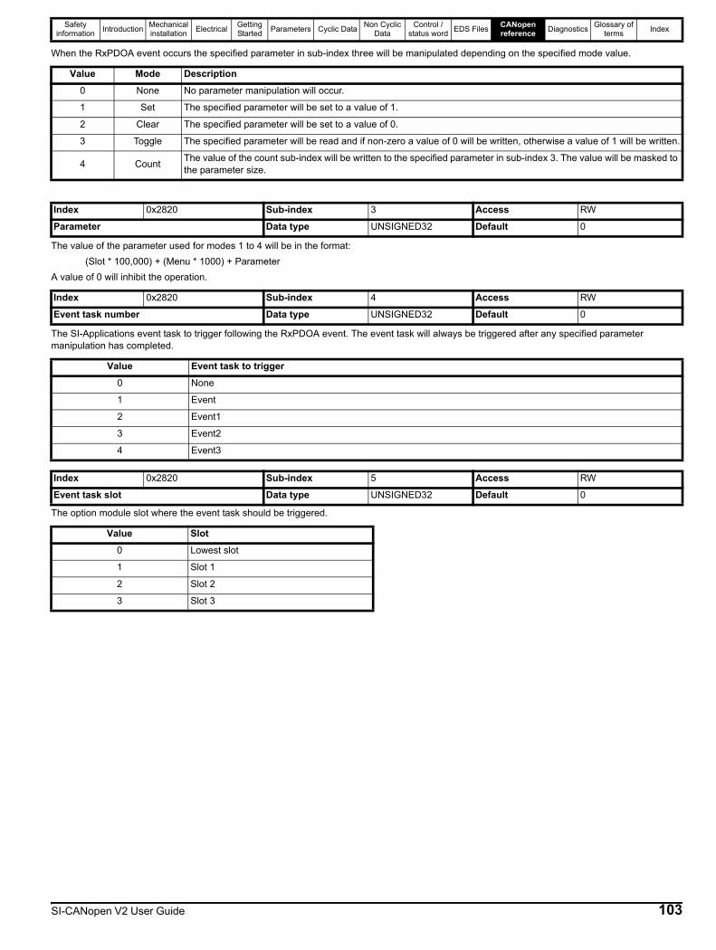
Safety information Introduction Mechanical
installation Electrical Getting Started Parameters Cyclic Data Non Cyclic
DataControl /
status word EDS Files CANopen reference Diagnostics Glossary of
terms Index
When the RxPDOA event occurs the specified parameter in sub-index three will be manipulated depending on the specified mode value.
The value of the parameter used for modes 1 to 4 will be in the format:(Slot * 100,000) + (Menu * 1000) + Parameter
A value of 0 will inhibit the operation.
The SI-Applications event task to trigger following the RxPDOA event. The event task will always be triggered after any specified parameter manipulation has completed.
The option module slot where the event task should be triggered.
Value Mode Description0 None No parameter manipulation will occur.
1 Set The specified parameter will be set to a value of 1.
2 Clear The specified parameter will be set to a value of 0.
3 Toggle The specified parameter will be read and if non-zero a value of 0 will be written, otherwise a value of 1 will be written.
4 Count The value of the count sub-index will be written to the specified parameter in sub-index 3. The value will be masked to the parameter size.
Index 0x2820 Sub-index 3 Access RW
Parameter Data type UNSIGNED32 Default 0
Index 0x2820 Sub-index 4 Access RW
Event task number Data type UNSIGNED32 Default 0
Value Event task to trigger0 None
1 Event
2 Event1
3 Event2
4 Event3
Index 0x2820 Sub-index 5 Access RW
Event task slot Data type UNSIGNED32 Default 0
Value Slot0 Lowest slot
1 Slot 1
2 Slot 2
3 Slot 3
SI-CANopen V2 User Guide 103
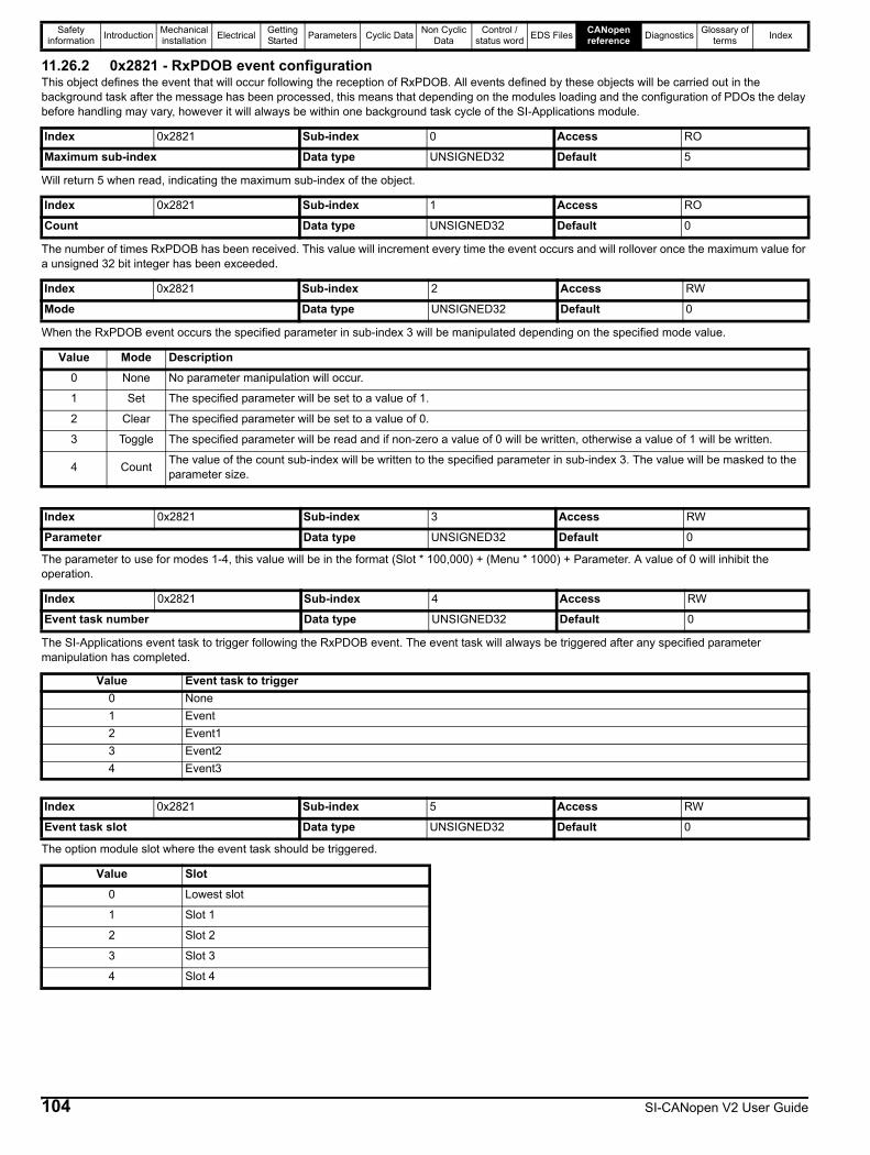
Safety information Introduction Mechanical
installation Electrical Getting Started Parameters Cyclic Data Non Cyclic
DataControl /
status word EDS Files CANopen reference Diagnostics Glossary of
terms Index
11.26.2 0x2821 - RxPDOB event configurationThis object defines the event that will occur following the reception of RxPDOB. All events defined by these objects will be carried out in the background task after the message has been processed, this means that depending on the modules loading and the configuration of PDOs the delay before handling may vary, however it will always be within one background task cycle of the SI-Applications module.
Will return 5 when read, indicating the maximum sub-index of the object.
The number of times RxPDOB has been received. This value will increment every time the event occurs and will rollover once the maximum value for a unsigned 32 bit integer has been exceeded.
When the RxPDOB event occurs the specified parameter in sub-index 3 will be manipulated depending on the specified mode value.
The parameter to use for modes 1-4, this value will be in the format (Slot * 100,000) + (Menu * 1000) + Parameter. A value of 0 will inhibit the operation.
The SI-Applications event task to trigger following the RxPDOB event. The event task will always be triggered after any specified parameter manipulation has completed.
The option module slot where the event task should be triggered.
Index 0x2821 Sub-index 0 Access RO
Maximum sub-index Data type UNSIGNED32 Default 5
Index 0x2821 Sub-index 1 Access RO
Count Data type UNSIGNED32 Default 0
Index 0x2821 Sub-index 2 Access RW
Mode Data type UNSIGNED32 Default 0
Value Mode Description0 None No parameter manipulation will occur.
1 Set The specified parameter will be set to a value of 1.
2 Clear The specified parameter will be set to a value of 0.
3 Toggle The specified parameter will be read and if non-zero a value of 0 will be written, otherwise a value of 1 will be written.
4 Count The value of the count sub-index will be written to the specified parameter in sub-index 3. The value will be masked to the parameter size.
Index 0x2821 Sub-index 3 Access RW
Parameter Data type UNSIGNED32 Default 0
Index 0x2821 Sub-index 4 Access RW
Event task number Data type UNSIGNED32 Default 0
Value Event task to trigger0 None1 Event2 Event13 Event24 Event3
Index 0x2821 Sub-index 5 Access RW
Event task slot Data type UNSIGNED32 Default 0
Value Slot0 Lowest slot
1 Slot 1
2 Slot 2
3 Slot 3
4 Slot 4
104 SI-CANopen V2 User Guide

Safety information Introduction Mechanical
installation Electrical Getting Started Parameters Cyclic Data Non Cyclic
DataControl /
status word EDS Files CANopen reference Diagnostics Glossary of
terms Index
11.26.3 0x2822 - RxPDOC event configurationThis object defines the event that will occur following the reception of RxPDOC. All events defined by these objects will be carried out in the background task after the message has been processed, this means that depending on the modules loading and the configuration of PDOs the delay before handling may vary, however it will always be within one background task cycle.
Will return 5 when read, indicating the maximum sub-index of the object.
The number of times RxPDOC has been received. This value will increment every time the event occurs, and will rollover once the maximum value for an unsigned 32 bit integer has been exceeded.
When the RxPDOC event occurs the specified parameter in sub-index 3 will be manipulated depending on the specified mode value.
The parameter to use for modes 1-4, this value will be in the format (Slot x 100,000) + (Menu x 1000) + Parameter. A value of 0 will inhibit the operation.
The SI-Applications event task to trigger following the RxPDOC event. The event task will always be triggered after any specified parameter manipulation has completed.
The option module slot where the event task should be triggered.
The option module slot where the event task should be triggered.
Index 0x2822 Sub-index 0 Access RO
Maximum sub-index Data type UNSIGNED32 Default 0
Index 0x2822 Sub-index 1 Access RO
Count Data type UNSIGNED32 Default 0
Index 0x2822 Sub-index 2 Access RW
Mode Data type UNSIGNED32 Default 0
Value Mode Description0 None No parameter manipulation will occur.
1 Set The specified parameter will be set to a value of 1.
2 Clear The specified parameter will be set to a value of 0.
3 Toggle The specified parameter will be read and if non-zero a value of 0 will be written, otherwise a value of 1 will be written.
4 Count The value of the count sub-index will be written to the specified parameter in sub-index 3. The value will be masked to the parameter size.
Index 0x2822 Sub-index 3 Access RW
Parameter Data type UNSIGNED32 Default 0
Index 0x2822 Sub-index 4 Access RW
Event task number Data type UNSIGNED32 Default 0
Value Event task to trigger0 None
1 Event
2 Event1
3 Event2
4 Event3
Index 0x2822 Sub-index 5 Access RW
Event task slot Data type UNSIGNED32 Default 0
Value Slot0 Lowest slot
1 Slot 1
2 Slot 2
3 Slot 3
4 Slot 4
SI-CANopen V2 User Guide 105
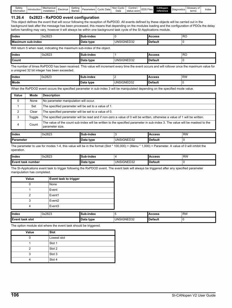
Safety information Introduction Mechanical
installation Electrical Getting Started Parameters Cyclic Data Non Cyclic
DataControl /
status word EDS Files CANopen reference Diagnostics Glossary of
terms Index
11.26.4 0x2823 - RxPDOD event configurationThis object defines the event that will occur following the reception of RxPDOD. All events defined by these objects will be carried out in the background task after the message has been processed, this means that depending on the modules loading and the configuration of PDOs the delay before handling may vary, however it will always be within one background task cycle of the SI-Applications module.
Will return 5 when read, indicating the maximum sub-index of the object.
The number of times RxPDOD has been received. This value will increment every time the event occurs and will rollover once the maximum value for a unsigned 32 bit integer has been exceeded.
When the RxPDOD event occurs the specified parameter in sub-index 3 will be manipulated depending on the specified mode value.
The parameter to use for modes 1-4, this value will be in the format (Slot * 100,000) + (Menu * 1,000) + Parameter. A value of 0 will inhibit the operation.
The SI-Applications event task to trigger following the RxPDOD event. The event task will always be triggered after any specified parameter manipulation has completed.
The option module slot where the event task should be triggered.
Index 0x2823 Sub-index 0 Access RO
Maximum sub-index Data type UNSIGNED32 Default 0
Index 0x2823 Sub-index 1 Access RO
Count Data type UNSIGNED32 Default 0
Index 0x2823 Sub-index 2 Access RW
Mode Data type UNSIGNED32 Default 0
Value Mode Description0 None No parameter manipulation will occur.
1 Set The specified parameter will be set to a value of 1.
2 Clear The specified parameter will be set to a value of 0.
3 Toggle The specified parameter will be read and if non-zero a value of 0 will be written, otherwise a value of 1 will be written.
4 Count The value of the count sub-index will be written to the specified parameter in sub-index 3. The value will be masked to the parameter size.
Index 0x2823 Sub-index 3 Access RW
Parameter Data type UNSIGNED32 Default 0
Index 0x2823 Sub-index 4 Access RW
Event task number Data type UNSIGNED32 Default 0
Value Event task to trigger0 None
1 Event
2 Event1
3 Event2
4 Event3
Index 0x2823 Sub-index 5 Access RW
Event task slot Data type UNSIGNED32 Default 0
Value Slot0 Lowest slot
1 Slot 1
2 Slot 2
3 Slot 3
4 Slot 4
106 SI-CANopen V2 User Guide

Safety information Introduction Mechanical
installation Electrical Getting Started Parameters Cyclic Data Non Cyclic
DataControl /
status word EDS Files CANopen reference Diagnostics Glossary of
terms Index
11.26.5 0x2830 - SYNC event configurationThis object defines the event that will occur following the reception of SYNC messages. All events defined by these objects will be carried out in the background task after the message has been processed, this means that depending on the modules loading and the configuration of PDOs the delay before handling may vary, however it will always be within one background task cycle of the SI-Applications module.
Will return 5 when read, indicating the maximum sub-index of the object.
The number of times the SYNC message has been received. This value will increment every time a SYNC message occurs and will rollover once the maximum value for a unsigned 32 bit integer has been exceeded.
When the SYNC message occurs the specified parameter in sub-index 3 will be manipulated depending on the specified mode value:
The parameter to use for modes 1-4, this value will be in the format (Slot * 100,000) + (Menu * 1,000) + Parameter. A value of 0 will inhibit the operation.
The SI-Applications event task to trigger following a SYNC messages. The event task will always be triggered after any specified parameter manipulation has completed.
The option module slot where the event task should be triggered.
Index 0x2830 Sub-index 0 Access RO
Maximum sub-index Data type UNSIGNED32 Default 5
Index 0x2830 Sub-index 1 Access RO
Count Data type UNSIGNED32 Default 0
Index 0x2830 Sub-index 2 Access RW
Mode Data type UNSIGNED32 Default 0
Value Mode Description0 None No parameter manipulation will occur.
1 Set The specified parameter will be set to a value of 1.
2 Clear The specified parameter will be set to a value of 0.
3 Toggle The specified parameter will be read and if non-zero a value of 0 will be written, otherwise a value of 1 will be written.
4 Count The value of the count sub-index will be written to the specified parameter in sub-index 3. The value will be masked to the param-eter size.
Index 0x2830 Sub-index 3 Access RW
Parameter Data type UNSIGNED32 Default 0
Index 0x2830 Sub-index 4 Access RW
Event task number Data type UNSIGNED32 Default 0
Value Event task to trigger0 None
1 Event
2 Event1
3 Event2
4 Event3
Index 0x2830 Sub-index 5 Access RW
Event task slot Data type UNSIGNED32 Default 0
Value Slot0 Lowest slot
1 Slot 1
2 Slot 2
3 Slot 3
4 Slot 4
SI-CANopen V2 User Guide 107
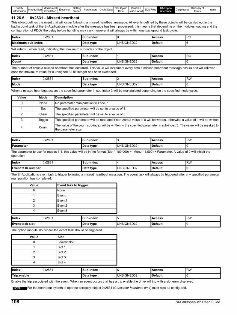
Safety information Introduction Mechanical
installation Electrical Getting Started Parameters Cyclic Data Non Cyclic
DataControl /
status word EDS Files CANopen reference Diagnostics Glossary of
terms Index
11.26.6 0x2831 - Missed heartbeatThis object defines the event that will occur following a missed heartbeat message. All events defined by these objects will be carried out in the background task of the SI-Applications module after the message has been processed, this means that depending on the modules loading and the configuration of PDOs the delay before handling may vary, however it will always be within one background task cycle.
Will return 6 when read, indicating the maximum sub-index of the object.
The number of times a missed heartbeat has occurred. This value will increment every time a missed heartbeat message occurs and will rollover once the maximum value for a unsigned 32 bit integer has been exceeded.
When a missed heartbeat occurs the specified parameter in sub-index 3 will be manipulated depending on the specified mode value.
The parameter to use for modes 1-4, this value will be in the format (Slot * 100,000) + (Menu * 1,000) + Parameter. A value of 0 will inhibit the operation.
The SI-Applications event task to trigger following a missed heartbeat message. The event task will always be triggered after any specified parameter manipulation has completed.
The option module slot where the event task should be triggered.
Enable the trip associated with the event. When an event occurs that has a trip enable the drive will trip with a slot error displayed.
Index 0x2831 Sub-index 0 Access RO
Maximum sub-index Data type UNSIGNED32 Default 6
Index 0x2831 Sub-index 1 Access RO
Count Data type UNSIGNED32 Default 0
Index 0x2831 Sub-index 2 Access RW
Mode Data type UNSIGNED32 Default 0
Value Mode Description0 None No parameter manipulation will occur.
1 Set The specified parameter will be set to a value of 1.
2 Clear The specified parameter will be set to a value of 0.
3 Toggle The specified parameter will be read and if non-zero a value of 0 will be written, otherwise a value of 1 will be written.
4 Count The value of the count sub-index will be written to the specified parameter in sub-index 3. The value will be masked to the parameter size.
Index 0x2831 Sub-index 3 Access RW
Parameter Data type UNSIGNED32 Default 0
Index 0x2831 Sub-index 4 Access RW
Event task number Data type UNSIGNED32 Default 0
Value Event task to trigger0 None1 Event2 Event13 Event24 Event3
Index 0x2831 Sub-index 5 Access RW
Event task slot Data type UNSIGNED32 Default 0
Value Slot0 Lowest slot1 Slot 12 Slot 23 Slot 34 Slot 4
Index 0x2831 Sub-index 6 Access RW
Trip enable Data type UNSIGNED32 Default 0
For the heartbeat system to operate correctly, object 0x2831 (Consumer heartbeat time) must also be configured.NOTE
108 SI-CANopen V2 User Guide
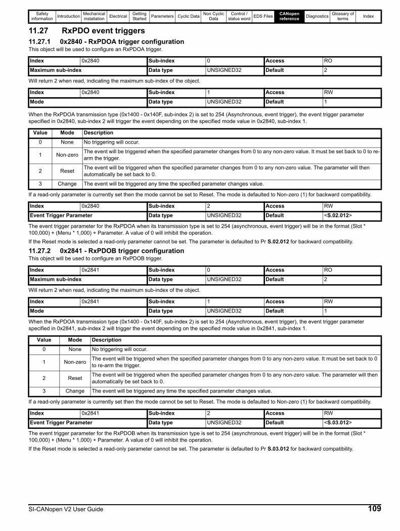
Safety information Introduction Mechanical
installation Electrical Getting Started Parameters Cyclic Data Non Cyclic
DataControl /
status word EDS Files CANopen reference Diagnostics Glossary of
terms Index
11.27 RxPDO event triggers11.27.1 0x2840 - RxPDOA trigger configurationThis object will be used to configure an RxPDOA trigger.
Will return 2 when read, indicating the maximum sub-index of the object.
When the RxPDOA transmission type (0x1400 - 0x140F, sub-index 2) is set to 254 (Asynchronous, event trigger), the event trigger parameter specified in 0x2840, sub-index 2 will trigger the event depending on the specified mode value in 0x2840, sub-index 1.
If a read-only parameter is currently set then the mode cannot be set to Reset. The mode is defaulted to Non-zero (1) for backward compatibility.
The event trigger parameter for the RxPDOA when its transmission type is set to 254 (asynchronous, event trigger) will be in the format (Slot * 100,000) + (Menu * 1,000) + Parameter. A value of 0 will inhibit the operation.If the Reset mode is selected a read-only parameter cannot be set. The parameter is defaulted to Pr S.02.012 for backward compatibility.
11.27.2 0x2841 - RxPDOB trigger configurationThis object will be used to configure an RxPDOB trigger.
Will return 2 when read, indicating the maximum sub-index of the object.
When the RxPDOA transmission type (0x1400 - 0x140F, sub-index 2) is set to 254 (Asynchronous, event trigger), the event trigger parameter specified in 0x2841, sub-index 2 will trigger the event depending on the specified mode value in 0x2841, sub-index 1.
If a read-only parameter is currently set then the mode cannot be set to Reset. The mode is defaulted to Non-zero (1) for backward compatibility.
The event trigger parameter for the RxPDOB when its transmission type is set to 254 (asynchronous, event trigger) will be in the format (Slot * 100,000) + (Menu * 1,000) + Parameter. A value of 0 will inhibit the operation.If the Reset mode is selected a read-only parameter cannot be set. The parameter is defaulted to Pr S.03.012 for backward compatibility.
Index 0x2840 Sub-index 0 Access RO
Maximum sub-index Data type UNSIGNED32 Default 2
Index 0x2840 Sub-index 1 Access RW
Mode Data type UNSIGNED32 Default 1
Value Mode Description0 None No triggering will occur.
1 Non-zero The event will be triggered when the specified parameter changes from 0 to any non-zero value. It must be set back to 0 to re-arm the trigger.
2 Reset The event will be triggered when the specified parameter changes from 0 to any non-zero value. The parameter will then automatically be set back to 0.
3 Change The event will be triggered any time the specified parameter changes value.
Index 0x2840 Sub-index 2 Access RW
Event Trigger Parameter Data type UNSIGNED32 Default <S.02.012>
Index 0x2841 Sub-index 0 Access RO
Maximum sub-index Data type UNSIGNED32 Default 2
Index 0x2841 Sub-index 1 Access RW
Mode Data type UNSIGNED32 Default 1
Value Mode Description0 None No triggering will occur.
1 Non-zero The event will be triggered when the specified parameter changes from 0 to any non-zero value. It must be set back to 0 to re-arm the trigger.
2 Reset The event will be triggered when the specified parameter changes from 0 to any non-zero value. The parameter will then automatically be set back to 0.
3 Change The event will be triggered any time the specified parameter changes value.
Index 0x2841 Sub-index 2 Access RW
Event Trigger Parameter Data type UNSIGNED32 Default <S.03.012>
SI-CANopen V2 User Guide 109

Safety information Introduction Mechanical
installation Electrical Getting Started Parameters Cyclic Data Non Cyclic
DataControl /
status word EDS Files CANopen reference Diagnostics Glossary of
terms Index
11.27.3 0x2842 - RxPDOC trigger configurationThis object will be used to configure an RxPDOC trigger.
Will return 2 when read, indicating the maximum sub-index of the object.
When the RxPDOA transmission type (0x1400 - 0x140F, sub-index 2) is set to 254 (Asynchronous, event trigger), the event trigger parameter specified in 0x2842, sub-index 2 will trigger the event depending on the specified mode value in 0x2842, sub-index 1.
If a read-only parameter is currently set then the mode cannot be set to Reset. The mode is defaulted to Non-zero (1) for backward compatibility.
The event trigger parameter for the RxPDOC when its transmission type is set to 254 (asynchronous, event trigger) will be in the format (Slot * 100,000) + (Menu * 1,000) + Parameter. A value of 0 will inhibit the operation.If the Reset mode is selected a read-only parameter cannot be set. The parameter is defaulted to Pr S.04.012 for backward compatibility.
11.27.4 0x2843 - RxPDOD trigger configurationThis object will be used to configure an RxPDOD trigger.
Will return 2 when read, indicating the maximum sub-index of the object.
When the RxPDOA transmission type (0x1400 - 0x140F, sub-index 2) is set to 254 (Asynchronous, event trigger), the event trigger parameter specified in 0x2842, sub-index 2 will trigger the event depending on the specified mode value in 0x2842, sub-index 1.
If a read-only parameter is currently set then the mode cannot be set to reset. The mode is defaulted to non-zero (1) for backward compatibility.
The event trigger parameter for the RxPDOD when its transmission type is set to 254 (asynchronous, event trigger) will be in the format (Slot * 100,000) + (Menu * 1,000) + Parameter. A value of 0 will inhibit the operation.If the Reset mode is selected a read-only parameter cannot be set. The parameter is defaulted to Pr S.05.012 for backward compatibility.
Index 0x2842 Sub-index 0 Access RO
Maximum sub-index Data type UNSIGNED32 Default 2
Index 0x2842 Sub-index 1 Access RW
Mode Data type UNSIGNED32 Default 1
Value Mode Description0 None No triggering will occur.
1 Non-zero The event will be triggered when the specified parameter changes from 0 to any non-zero value. It must be set back to 0 to re-arm the trigger.
2 Reset The event will be triggered when the specified parameter changes from 0 to any non-zero value. The parameter will then automatically be set back to 0.
3 Change The event will be triggered any time the specified parameter changes value.
Index 0x2842 Sub-index 2 Access RO
Event Trigger Parameter Data type UNSIGNED32 Default <S.04.012>
Index 0x2843 Sub-index 0 Access RO
Maximum sub-index Data type UNSIGNED32 Default 2
Index 0x2843 Sub-index 1 Access RW
Mode Data type UNSIGNED32 Default 1
Value Mode Description0 None No triggering will occur.
1 Non-zero The event will be triggered when the specified parameter changes from 0 to any non-zero value. It must be set back to 0 to re-arm the trigger.
2 Reset The event will be triggered when the specified parameter changes from 0 to any non-zero value. The parameter will then automatically be set back to 0.
3 Change The event will be triggered any time the specified parameter changes value.
Index 0x2843 Sub-index 2 Access RW
Event Trigger Parameter Data type UNSIGNED32 Default <S.05.012>
110 SI-CANopen V2 User Guide

Safety information Introduction Mechanical
installation Electrical Getting Started Parameters Cyclic Data Non Cyclic
DataControl /
status word EDS Files CANopen reference Diagnostics Glossary of
terms Index
11.28 TxPDO event triggers11.28.1 0x2850 - TxPDOA trigger configurationThis object will be used to configure a TxPDOA trigger.
Will return 2 when read, indicating the maximum sub-index of the object.
When the TxPDOA transmission type (0x1800 - 0x180F, sub-index 2) is set to 254 (Asynchronous, event trigger), the event trigger parameter specified in 0x2850, sub-index 2 will trigger the event depending on the specified mode value in 0x2850, sub-index 1.
If a read-only parameter is currently set then the mode cannot be set to reset. The mode is defaulted to Non-zero (1) for backward compatibility.
The event trigger parameter for the TxPDOA when its transmission type is set to 254 (asynchronous, event trigger) will be in the format (Slot * 100,000) + (Menu * 1,000) + Parameter. A value of 0 will inhibit the operation.If the Reset mode is selected a read-only parameter cannot be set. The parameter is defaulted to Pr S.02.012 for backward compatibility.
11.28.2 0x2851 - TxPDOB trigger configurationThis object will be used to configure a TxPDOB trigger.
Will return 2 when read, indicating the maximum sub-index of the object.
When the TxPDOB transmission type (0x1800 - 0x180F, sub-index 2) is set to 254 (Asynchronous, event trigger), the event trigger parameter specified in 0x2851, sub-index 2 will trigger the event depending on the specified mode value in 0x2851, sub-index 1.
If a read-only parameter is currently set then the mode cannot be set to reset. The mode is defaulted to non-zero (1) for backward compatibility.
The event trigger parameter for the TxPDOB when its transmission type is set to 254 (asynchronous, event trigger) will be in the format (Slot * 100,000) + (Menu * 1,000) + Parameter. A value of 0 will inhibit the operation.If the Reset mode is selected a read-only parameter cannot be set. The parameter is defaulted to Pr S.03.012 for backward compatibility.
Index 0x2850 Sub-index 0 Access RO
Maximum sub-index Data type UNSIGNED32 Default 2
Index 0x2850 Sub-index 1 Access RW
Mode Data type UNSIGNED32 Default 1
Value Mode Description
0 None No triggering will occur.
1 Non-zero The event will be triggered when the specified parameter changes from 0 to any non-zero value. It must be set back to 0 to re-arm the trigger.
2 Reset The event will be triggered when the specified parameter changes from 0 to any non-zero value. The parameter will then automatically be set back to 0.
3 Change The event will be triggered any time the specified parameter changes value.
Index 0x2850 Sub-index 2 Access RW
Event Trigger parameter Data type UNSIGNED32 Default <S.02.012>
Index 0x2851 Sub-index 0 Access RO
Maximum sub-index Data type UNSIGNED32 Default 2
Index 0x2851 Sub-index 1 Access RW
Mode Data type UNSIGNED32 Default 1
Value Mode Description
0 None No triggering will occur.
1 Non-zero The event will be triggered when the specified parameter changes from 0 to any non-zero value. It must be set back to 0 to re-arm the trigger.
2 Reset The event will be triggered when the specified parameter changes from 0 to any non-zero value. The parameter will then automatically be set back to 0.
3 Change The event will be triggered any time the specified parameter changes value.
Index 0x2851 Sub-index 2 Access RW
Event Trigger parameter Data type UNSIGNED32 Default <S.03.012>
SI-CANopen V2 User Guide 111
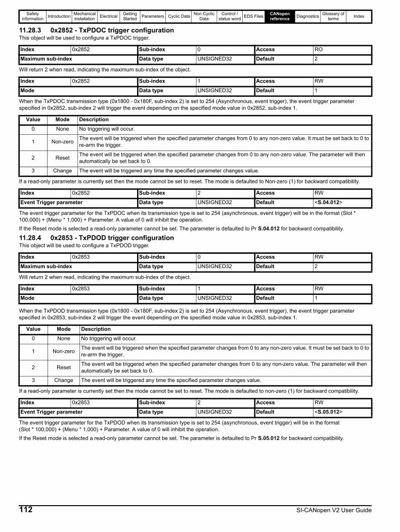
Safety information Introduction Mechanical
installation Electrical Getting Started Parameters Cyclic Data Non Cyclic
DataControl /
status word EDS Files CANopen reference Diagnostics Glossary of
terms Index
11.28.3 0x2852 - TxPDOC trigger configurationThis object will be used to configure a TxPDOC trigger.
Will return 2 when read, indicating the maximum sub-index of the object.
When the TxPDOC transmission type (0x1800 - 0x180F, sub-index 2) is set to 254 (Asynchronous, event trigger), the event trigger parameter specified in 0x2852, sub-index 2 will trigger the event depending on the specified mode value in 0x2852, sub-index 1.
If a read-only parameter is currently set then the mode cannot be set to reset. The mode is defaulted to Non-zero (1) for backward compatibility.
The event trigger parameter for the TxPDOC when its transmission type is set to 254 (asynchronous, event trigger) will be in the format (Slot * 100,000) + (Menu * 1,000) + Parameter. A value of 0 will inhibit the operation.If the Reset mode is selected a read-only parameter cannot be set. The parameter is defaulted to Pr S.04.012 for backward compatibility.
11.28.4 0x2853 - TxPDOD trigger configurationThis object will be used to configure a TxPDOD trigger.
Will return 2 when read, indicating the maximum sub-index of the object.
When the TxPDOD transmission type (0x1800 - 0x180F, sub-index 2) is set to 254 (Asynchronous, event trigger), the event trigger parameter specified in 0x2853, sub-index 2 will trigger the event depending on the specified mode value in 0x2853, sub-index 1.
If a read-only parameter is currently set then the mode cannot be set to reset. The mode is defaulted to non-zero (1) for backward compatibility.
The event trigger parameter for the TxPDOD when its transmission type is set to 254 (asynchronous, event trigger) will be in the format(Slot * 100,000) + (Menu * 1,000) + Parameter. A value of 0 will inhibit the operation.If the Reset mode is selected a read-only parameter cannot be set. The parameter is defaulted to Pr S.05.012 for backward compatibility.
Index 0x2852 Sub-index 0 Access RO
Maximum sub-index Data type UNSIGNED32 Default 2
Index 0x2852 Sub-index 1 Access RW
Mode Data type UNSIGNED32 Default 1
Value Mode Description0 None No triggering will occur.
1 Non-zero The event will be triggered when the specified parameter changes from 0 to any non-zero value. It must be set back to 0 to re-arm the trigger.
2 Reset The event will be triggered when the specified parameter changes from 0 to any non-zero value. The parameter will then automatically be set back to 0.
3 Change The event will be triggered any time the specified parameter changes value.
Index 0x2852 Sub-index 2 Access RW
Event Trigger parameter Data type UNSIGNED32 Default <S.04.012>
Index 0x2853 Sub-index 0 Access RW
Maximum sub-index Data type UNSIGNED32 Default 2
Index 0x2853 Sub-index 1 Access RW
Mode Data type UNSIGNED32 Default 1
Value Mode Description0 None No triggering will occur.
1 Non-zero The event will be triggered when the specified parameter changes from 0 to any non-zero value. It must be set back to 0 to re-arm the trigger.
2 Reset The event will be triggered when the specified parameter changes from 0 to any non-zero value. The parameter will then automatically be set back to 0.
3 Change The event will be triggered any time the specified parameter changes value.
Index 0x2853 Sub-index 2 Access RW
Event Trigger parameter Data type UNSIGNED32 Default <S.05.012>
112 SI-CANopen V2 User Guide

Safety information Introduction Mechanical
installation Electrical Getting Started Parameters Cyclic Data Non Cyclic
DataControl /
status word EDS Files CANopen reference Diagnostics Glossary of
terms Index
11.29 Inter-option DPLCAN InterfaceThe inter-option DPLCAN interface between the SI-CANopen V2 and Applications modules provide the Applications modules with simple CAN Master functionality allowing the Applications modules to request from the SI-CANopen V2 module to send and receive raw CAN frames.The following Applications modules are supported:• SI-Applications Plus• SI-Applications Compact• MCi2x0The following Applications DPLCAN commands are supported:• EnableCANTrips• CANStatus• ResetCANTimer• GETCAN• PUTCAN• CANStatusAll• CANSetup• CANGetNodeAddr• CANReady• CANConfigEventFor more information and use of these functions, please refer to the online help provided in the Applications module configuration tool (SyPTPro or Machine Control Studio).In order to use the DPLCAN interface, the list of DPL parameters to be associated with a CANopen object must be created, object 0x2860 (Startup Object List) is provided for this purpose.
11.29.1 Associating CANopen objects to DPL variablesInteger variables in an Applications user program can be associated with an object in the CANopen object dictionary, allowing the CANopen master controller to directly read from and write to DPL user program variables.These associations must be made within the Initial task of the user program. If they are executed in any other task, then the function will return the error status 6 (task error).The association is made using the AssociateIntOpComms function, this function creates and defines the attributes of the associated object as defined in Table 11-28.DPL variables can be either 1, 8, 16 or 32-bit integers (signed or unsigned), if a DPL variable is associated with an object of less than 32 bits or the value of the DPL variable exceeds the permissible associated object value range, then the user must ensure the DPL variable value does not exceed the associated object size or range.The format for the association function is:
Status% = AssociateIntOpComms(Index%, Subindex%, Variable%, Sign%, Size%, Read%, Write%).
Table 11-28 AssociateIntOpComms attributes
ExamplesThe following function call can be used in an Applications user program to create an association between a CANopen object (0x6000, sub-index 1) and a DPL variable (MyVar%), making a signed 16-bit read-only object. The DPL variable Status% will contain the function’s return status value.
Status% = AssociateIntOpComms(0x6000, 1, MyVar%, 1, 16, 1, 0).If the object is required to be a read/write object then the following function call can be used:
Status% = AssociateIntOpComms(0x6000, 1, MyVar%, 1, 16, 1, 1).
Argument Range Description
Index%0x1000,
0x2101 to 0x25FF,0x3000 to 0x9FFF
Specifies the CANopen object index to associate with the DPL variable (Variable%)
SubIndex% 0x00 to 0xFFSpecifies the CANopen object sub-index to associate with the DPL variable (Variable%)
Variable% N/ASpecifies the DPL variable to associate with the CANopen object (Index%:Subindex%)
Sign% 0 or 10 = unsigned1 = signed
Size% 1, 8, 16 or 32 Specifies the CANopen object size in bits
Read% 0 or 10 = object cannot be read by SI-CANopen V21 = object can be read by SI-CANopen V2
Write% 0 or 10 = object cannot be written by SI-CANopen V21 = object can be written by SI-CANopen V2
SI-CANopen V2 User Guide 113

Safety information Introduction Mechanical
installation Electrical Getting Started Parameters Cyclic Data Non Cyclic
DataControl /
status word EDS Files CANopen reference Diagnostics Glossary of
terms Index
11.29.2 Maintaining DPL variablesWhen an association is created, the size and format attributes are used to control access to the DPL variable from the SI-CANopen module. The Applications module will restrict access to the DPL variable, based on the specified attributes (i.e. it will not allow a value to be written to a read-only association).The Applications module does not automatically maintain the associated DPL variables. The DPL program still has full access and control over all DPL variables, so it is possible for the Applications program to write a full 32-bit value to a DPL variable, even though it has been associated with an 8-bit CANopen object. If the CANopen object is subsequently read, the DPL variable will be masked, and the Applications module will only pass the low 8-bits to the SI-CANopen module. The same principle applies to Boolean and 16-bit objects.If an association has been created declaring an 8-bit read-only object, the DPL program can still write a new value to the DPL variable, and the complete 32-bit range is still available.It is possible to have multiple associations with different attributes made to the same DPL variable, provided that the index and sub-index references are unique in each case.If an error occurs with the association, for example, the object size is declared incorrectly, then the invalid background association error (108) will trip the drive.
11.29.3 0x2860 - Startup Object ListObject 0x2860 is not defined in the SI-CANopen V2 module, but can be defined in an associated DPL user program on an SI-Applications (Plus/Compact) module or an MCi2x0 module. This object, if associated, will be read by the SI-CANopen V2 module during the initialisation stage and can be used to initialise any writable object dictionary entries.Table 11-29 Startup object list
The sub-index is used to set the maximum number of sub-indexes for the object, each object definition uses two sub-indexes, the first sub-index is the object definition reference and the second sub-index is the value to be written, so to define two objects to initialise the maximum number of sub-indexes should be set to four.ExampleThe following code is written for the SI-Applications Plus (or Compact) and demonstrates how the startup object can be used to set other object values during initialisation, this code is provided as an example only, no error checking is performed.When the Initial task in the SI-Applications Plus module is run, the example code below would configure RxPDO1 with two mappings (Pr 0.20.021 and Pr 0.20.022), TxPDO1 with two mappings (Pr 0.20.023 and Pr 0.20.024).
If an error occurs during the handling of object 0x2860, an ‘SLx.Er’ will occur and the diagnostics will report a Configuration Error (4) in Pr S.01.006.
Sub-index Description Example usage0 Maximum sub-index Should be set to 2 * number of objects
1 1st Object definition0x12345620Object 0x1234, sub-index 0x56, length 32 bits
2 1st Object value Value to be written to object 0x1234, sub-index 0x56… … …
2 * n - 1 nth Object definition 0x18000108Object 0x1800, sub-index 0x01, length 8 bits
2 * n nth Object value Value to be written to object 0x1800, sub-index 0x01
114 SI-CANopen V2 User Guide
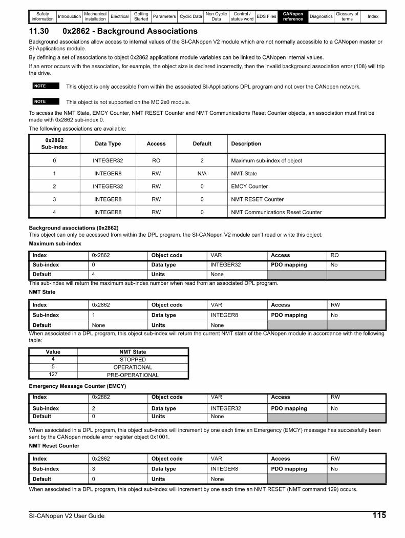
Safety information Introduction Mechanical
installation Electrical Getting Started Parameters Cyclic Data Non Cyclic
DataControl /
status word EDS Files CANopen reference Diagnostics Glossary of
terms Index
11.30 0x2862 - Background AssociationsBackground associations allow access to internal values of the SI-CANopen V2 module which are not normally accessible to a CANopen master or SI-Applications module.By defining a set of associations to object 0x2862 applications module variables can be linked to CANopen internal values.If an error occurs with the association, for example, the object size is declared incorrectly, then the invalid background association error (108) will trip the drive.
To access the NMT State, EMCY Counter, NMT RESET Counter and NMT Communications Reset Counter objects, an association must first be made with 0x2862 sub-index 0.The following associations are available:
Background associations (0x2862)This object can only be accessed from within the DPL program, the SI-CANopen V2 module can’t read or write this object.Maximum sub-index
This sub-index will return the maximum sub-index number when read from an associated DPL program.NMT State
When associated in a DPL program, this object sub-index will return the current NMT state of the CANopen module in accordance with the following table:
Emergency Message Counter (EMCY)
When associated in a DPL program, this object sub-index will increment by one each time an Emergency (EMCY) message has successfully been sent by the CANopen module error register object 0x1001.NMT Reset Counter
When associated in a DPL program, this object sub-index will increment by one each time an NMT RESET (NMT command 129) occurs.
This object is only accessible from within the associated SI-Applications DPL program and not over the CANopen network.
This object is not supported on the MCi2x0 module.
0x2862 Sub-index Data Type Access Default Description
0 INTEGER32 RO 2 Maximum sub-index of object
1 INTEGER8 RW N/A NMT State
2 INTEGER32 RW 0 EMCY Counter
3 INTEGER8 RW 0 NMT RESET Counter
4 INTEGER8 RW 0 NMT Communications Reset Counter
Index 0x2862 Object code VAR Access RO
Sub-index 0 Data type INTEGER32 PDO mapping No
Default 4 Units None
Index 0x2862 Object code VAR Access RW
Sub-index 1 Data type INTEGER8 PDO mapping No
Default None Units None
Value NMT State4 STOPPED5 OPERATIONAL
127 PRE-OPERATIONAL
Index 0x2862 Object code VAR Access RW
Sub-index 2 Data type INTEGER32 PDO mapping NoDefault 0 Units None
Index 0x2862 Object code VAR Access RW
Sub-index 3 Data type INTEGER8 PDO mapping No
Default 0 Units None
NOTE
NOTE
SI-CANopen V2 User Guide 115

Safety information Introduction Mechanical
installation Electrical Getting Started Parameters Cyclic Data Non Cyclic
DataControl /
status word EDS Files CANopen reference Diagnostics Glossary of
terms Index
NMT Communications Reset Counter
When associated in a DPL program, this object sub-index will increment by one each time an NMT Communications Reset (NMT command 130) occurs.
11.31 0x3000 - Position Feedback Encoder Source
This object is used to select the source for the position controller feedback and CiA 402 position feedback objects even if position control is not being used.The following table shows the possible values.Table 11-30 Position feedback encoder source
This object is evaluated on a change of drive operation mode.
11.32 0x3003 - Homing SourceThis object is used to select the digital input source for the homing switch and the freeze or marker source for homing.Last sub-index
This sub-index will return 2 when read, indicating the last sub-index of the object.Homing switch source
This sub-index selects the digital input/output number (1 to 6) to be used as the source for the homing switch. The selected digital input/output must be configured as an input.This value is read when the CiA 402 homing operation mode is enabled.Index source
This sub-index selects the source trigger signal for the homing mode.
Index 0x2862 Object code VAR Access RW
Sub-index 4 Data type INTEGER8 PDO mapping No
Default 0 Units None
Index 0x3000 Object code VAR Access RW
Sub-index 0 Data type UNSIGNED8 PDO mapping Yes
Default 0 Units None
Value Description0 The feedback source will use the drive motor controller feedback source selected in Pr 03.0261 Drive feedback source P1 interface2 Drive feedback source P2 interface3 Slot 1 position feedback module P1 interface4 Slot 1 position feedback module P2 interface5 Slot 2 position feedback module P1 interface6 Slot 2 position feedback module P2 interface7 Slot 3 position feedback module P1 interface8 Slot 3 position feedback module P2 interface9 Slot 4 position feedback module P1 interface
10 Slot 4 position feedback module P2 interface11 Sensorless (the sensorless algorithm estimates the position feedback), this will be ignored if no encoder input is present
Index 0x3003 Object code VAR Access RO
Sub-index 0 Data type UNSIGNED8 PDO mapping No
Default 2 Units None
Index 0x3003 Object code VAR Access RW
Sub-index 1 Data type UNSIGNED8 PDO mapping Yes
Default 5 Units None
Index 0x3003 Object code VAR Access RW
Sub-index 2 Data type UNSIGNED8 PDO mapping Yes
Default 0 Units None
116 SI-CANopen V2 User Guide
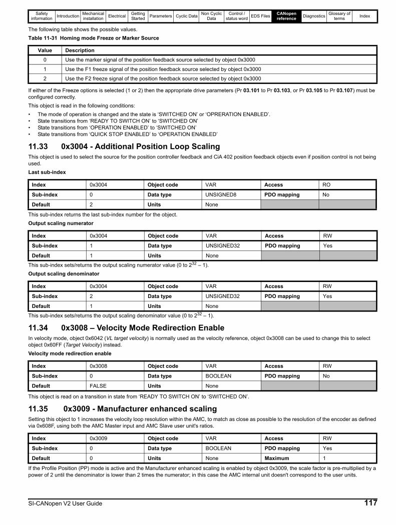
Safety information Introduction Mechanical
installation Electrical Getting Started Parameters Cyclic Data Non Cyclic
DataControl /
status word EDS Files CANopen reference Diagnostics Glossary of
terms Index
The following table shows the possible values.Table 11-31 Homing mode Freeze or Marker Source
If either of the Freeze options is selected (1 or 2) then the appropriate drive parameters (Pr 03.101 to Pr 03.103, or Pr 03.105 to Pr 03.107) must be configured correctly.This object is read in the following conditions:• The mode of operation is changed and the state is ‘SWITCHED ON’ or ‘OPRERATION ENABLED’.• State transitions from ‘READY TO SWITCH ON’ to ‘SWITCHED ON’• State transitions from ‘OPERATION ENABLED’ to ‘SWITCHED ON’• State transitions from ‘QUICK STOP ENABLED’ to ‘OPERATION ENABLED’
11.33 0x3004 - Additional Position Loop ScalingThis object is used to select the source for the position controller feedback and CiA 402 position feedback objects even if position control is not being used.Last sub-index
This sub-index returns the last sub-index number for the object.Output scaling numerator
This sub-index sets/returns the output scaling numerator value (0 to 232 – 1).Output scaling denominator
This sub-index sets/returns the output scaling denominator value (0 to 232 – 1).
11.34 0x3008 – Velocity Mode Redirection EnableIn velocity mode, object 0x6042 (VL target velocity) is normally used as the velocity reference, object 0x3008 can be used to change this to select object 0x60FF (Target Velocity) instead.Velocity mode redirection enable
This object is read on a transition in state from ‘READY TO SWITCH ON’ to ‘SWITCHED ON’.
11.35 0x3009 - Manufacturer enhanced scalingSetting this object to 1 increases the velocity loop resolution within the AMC, to match as close as possible to the resolution of the encoder as defined via 0x608F, using both the AMC Master input and AMC Slave user unit's ratios.
If the Profile Position (PP) mode is active and the Manufacturer enhanced scaling is enabled by object 0x3009, the scale factor is pre-multiplied by a power of 2 until the denominator is lower than 2 times the numerator; in this case the AMC internal unit doesn't correspond to the user units.
Value Description0 Use the marker signal of the position feedback source selected by object 0x3000
1 Use the F1 freeze signal of the position feedback source selected by object 0x3000
2 Use the F2 freeze signal of the position feedback source selected by object 0x3000
Index 0x3004 Object code VAR Access RO
Sub-index 0 Data type UNSIGNED8 PDO mapping No
Default 2 Units None
Index 0x3004 Object code VAR Access RW
Sub-index 1 Data type UNSIGNED32 PDO mapping Yes
Default 1 Units None
Index 0x3004 Object code VAR Access RW
Sub-index 2 Data type UNSIGNED32 PDO mapping Yes
Default 1 Units None
Index 0x3008 Object code VAR Access RW
Sub-index 0 Data type BOOLEAN PDO mapping No
Default FALSE Units None
Index 0x3009 Object code VAR Access RW
Sub-index 0 Data type BOOLEAN PDO mapping Yes
Default 0 Units None Maximum 1
SI-CANopen V2 User Guide 117
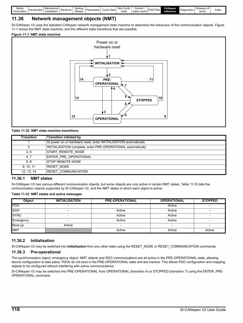
Safety information Introduction Mechanical
installation Electrical Getting Started Parameters Cyclic Data Non Cyclic
DataControl /
status word EDS Files CANopen reference Diagnostics Glossary of
terms Index
11.36 Network management objects (NMT)SI-CANopen V2 uses the standard CANopen network management state machine to determine the behaviour of the communication objects. Figure 11-1 shows the NMT state machine, and the different state transitions that are possible.Figure 11-1 NMT state machine
11.36.1 NMT statesSI-CANopen V2 has various different communication objects, but some objects are only active in certain NMT states. Table 11-33 lists the communication objects supported by SI-CANopen V2, and the NMT states in which each object is active.
11.36.2 InitialisationSI-CANopen V2 may be switched into Initialisation from any other state using the RESET_NODE or RESET_COMMUNICATION commands.
11.36.3 Pre-operationalThe synchronisation object, emergency object, NMT objects and SDO communications are all active in the PRE-OPERATIONAL state, allowing device configuration to take place. PDOs do not exist in the PRE-OPERATIONAL state and are inactive. This allows PDO configuration and mapping objects to be configured without interfering with active communications.SI-CANopen V2 may be switched into PRE-OPERATIONAL from OPERATIONAL (transition 4) or STOPPED (transition 7) using the ENTER_PRE-OPERATIONAL command.
Table 11-32 NMT state machine transitions
Transition Transition initiated by1 At power on or hardware reset, enter INITIALISATION automatically2 INITIALISATION complete, enter PRE-OPERATIONAL automatically
3, 6 START_REMOTE_NODE4, 7 ENTER_PRE_OPERATIONAL5, 8 STOP REMOTE NODE
9, 10, 11 RESET_NODE12, 13, 14 RESET_COMMUNICATION
Table 11-33 NMT states and active messages
Object INITIALISATION PRE-OPERATIONAL OPERATIONAL STOPPEDPDO - - Active -SDO - Active Active -SYNC - Active Active -Emergency - Active Active -Boot-up Active - - -NMT Active Active Active
INITIALISATION
214
7PRE-
OPERATIONAL
STOPPED
OPERATIONAL
1
3
13
12
11
10
9
5
8
6
4
Power on orhardware reset
118 SI-CANopen V2 User Guide
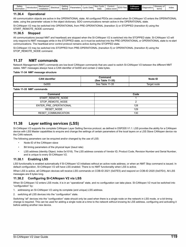
Safety information Introduction Mechanical
installation Electrical Getting Started Parameters Cyclic Data Non Cyclic
DataControl /
status word EDS Files CANopen reference Diagnostics Glossary of
terms Index
11.36.4 OperationalAll communication objects are active in the OPERATIONAL state. All configured PDOs are created when SI-CANopen V2 enters the OPERATIONAL state, using the parameter values in the object dictionary. SDO communications remain active in the OPERATIONAL state.SI-CANopen V2 may be switched into OPERATIONAL from PRE-OPERATIONAL (transition 3) or STOPPED (transition 6) using the START_REMOTE_NODE command.
11.36.5 StoppedAll communications (except NMT and heartbeat) are stopped when the SI-CANopen V2 is switched into the STOPPED state. SI-CANopen V2 will only respond to NMT messages while in the STOPPED state, so it must be switched into the PRE-OPERATIONAL or OPERATIONAL state to re-start communications. The heartbeat error control protocol remains active during the STOPPED state.SI-CANopen V2 may be switched into STOPPED from PRE-OPERATIONAL (transition 5) or OPERATIONAL (transition 8) using the STOP_REMOTE_NODE command.
11.37 NMT commandsNetwork Management (NMT) commands are low-level CANopen commands that are used to switch SI-CANopen V2 between the different NMT states. NMT messages always have a CAN identifier of 0x000 and contain 2 data bytes.
11.38 Layer setting services (LSS)SI-CANopen V2 supports the complete CANopen Layer Setting Service protocol, as defined in DSP205 V1.1. LSS provides the ability for a CANopen device with LSS Master capabilities to enquire and change the settings of certain parameters of the local layers on a LSS Slave CANopen device via the CAN network.The following parameters can be enquired and/or changed by the use of LSS:
• Node-ID of the CANopen slave
• Bit timing parameters of the physical layer (baud rate)
• LSS address (Identity Object, Index 0x1018). The LSS address consists of Vendor ID, Product Code, Revision Number and Serial Number, and is unique to every SI-CANopen V2.
11.38.1 Enabling LSSLSS functionality is enabled automatically if SI-CANopen V2 initialises without an active node address, or when an NMT Stop command is issued. In default configuration, SI-CANopen V2 will have LSS enabled. There is no NMT functionality when LSS is active.When LSS is active, all CANopen devices will receive LSS commands on COB-ID 2021 (0x07E5) and respond on COB-ID 2020 (0x07E4). All LSS messages are 8 bytes long.
11.38.2 Configuring SI-CANopen V2 via LSSWhen SI-CANopen V2 enters LSS mode, it is in an “operational” state, and no configuration can take place. SI-CANopen V2 must be switched into “configuration” by:1. addressing an SI-CANopen V2 using its complete (and unique) LSS address.
2. switching all LSS devices into the “configuration” state.
Switching “all” devices into the “configuration” state should only be used when there is a single node on the network in LSS mode, or a bit timing change is required. This can be used for adding a single node at a time to the network without knowing its LSS address, configuring and activating it before adding another new device.
Table 11-34 NMT message structure
CAN identifier Command (See Table 11-35) Node ID
0x000 See Table 11-35 Target node
Table 11-35 NMT commands
Command CodeSTART_REMOTE_NODE 1STOP_REMOTE_NODE 2
ENTER_PRE_OPERTATIONAL 128RESET_NODE 129
RESET_COMMUNICATION 130
SI-CANopen V2 User Guide 119
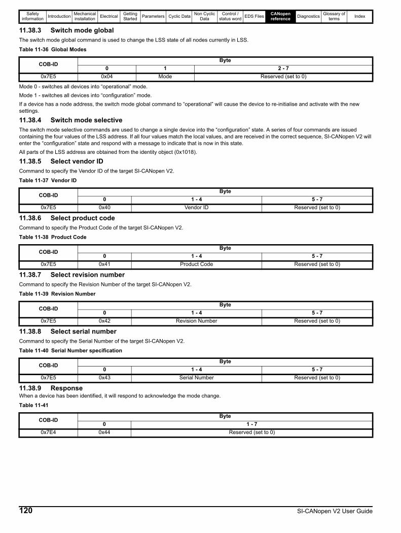
Safety information Introduction Mechanical
installation Electrical Getting Started Parameters Cyclic Data Non Cyclic
DataControl /
status word EDS Files CANopen reference Diagnostics Glossary of
terms Index
11.38.3 Switch mode globalThe switch mode global command is used to change the LSS state of all nodes currently in LSS.
Mode 0 - switches all devices into “operational” mode.Mode 1 - switches all devices into “configuration” mode.If a device has a node address, the switch mode global command to “operational” will cause the device to re-initialise and activate with the new settings.
11.38.4 Switch mode selectiveThe switch mode selective commands are used to change a single device into the “configuration” state. A series of four commands are issued containing the four values of the LSS address. If all four values match the local values, and are received in the correct sequence, SI-CANopen V2 will enter the “configuration” state and respond with a message to indicate that is now in this state.All parts of the LSS address are obtained from the identity object (0x1018).
11.38.5 Select vendor IDCommand to specify the Vendor ID of the target SI-CANopen V2.
11.38.6 Select product codeCommand to specify the Product Code of the target SI-CANopen V2.
11.38.7 Select revision numberCommand to specify the Revision Number of the target SI-CANopen V2.
11.38.8 Select serial numberCommand to specify the Serial Number of the target SI-CANopen V2.
11.38.9 ResponseWhen a device has been identified, it will respond to acknowledge the mode change.
Table 11-36 Global Modes
COB-IDByte
0 1 2 - 70x7E5 0x04 Mode Reserved (set to 0)
Table 11-37 Vendor ID
COB-IDByte
0 1 - 4 5 - 70x7E5 0x40 Vendor ID Reserved (set to 0)
Table 11-38 Product Code
COB-IDByte
0 1 - 4 5 - 70x7E5 0x41 Product Code Reserved (set to 0)
Table 11-39 Revision Number
COB-IDByte
0 1 - 4 5 - 70x7E5 0x42 Revision Number Reserved (set to 0)
Table 11-40 Serial Number specification
COB-IDByte
0 1 - 4 5 - 70x7E5 0x43 Serial Number Reserved (set to 0)
Table 11-41
COB-IDByte
0 1 - 70x7E4 0x44 Reserved (set to 0)
120 SI-CANopen V2 User Guide
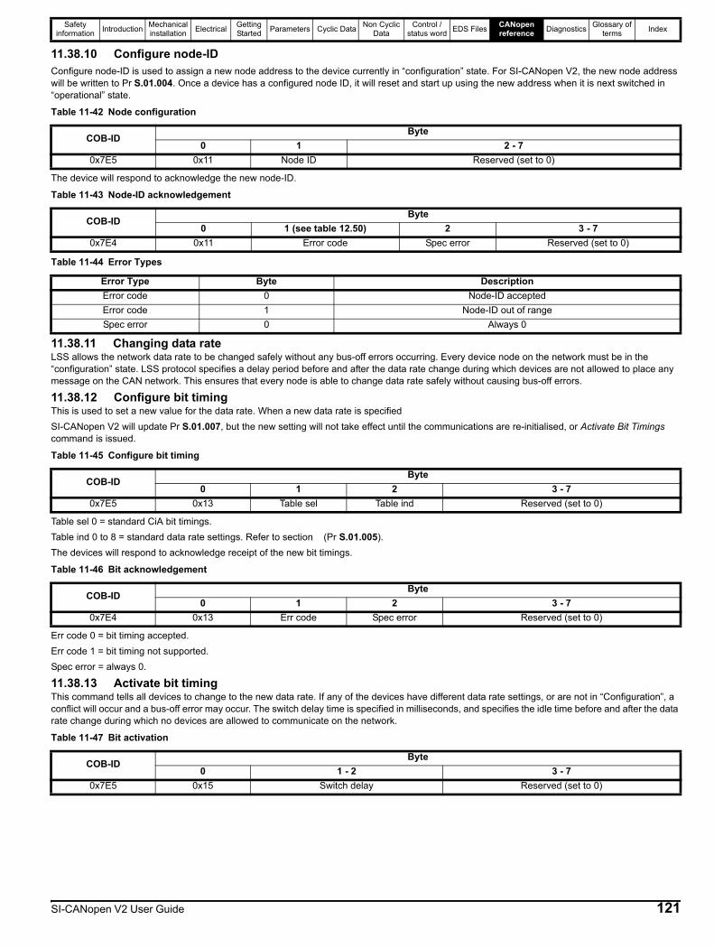
Safety information Introduction Mechanical
installation Electrical Getting Started Parameters Cyclic Data Non Cyclic
DataControl /
status word EDS Files CANopen reference Diagnostics Glossary of
terms Index
11.38.10 Configure node-IDConfigure node-ID is used to assign a new node address to the device currently in “configuration” state. For SI-CANopen V2, the new node address will be written to Pr S.01.004. Once a device has a configured node ID, it will reset and start up using the new address when it is next switched in “operational” state.
The device will respond to acknowledge the new node-ID.
11.38.11 Changing data rateLSS allows the network data rate to be changed safely without any bus-off errors occurring. Every device node on the network must be in the “configuration” state. LSS protocol specifies a delay period before and after the data rate change during which devices are not allowed to place any message on the CAN network. This ensures that every node is able to change data rate safely without causing bus-off errors.
11.38.12 Configure bit timingThis is used to set a new value for the data rate. When a new data rate is specifiedSI-CANopen V2 will update Pr S.01.007, but the new setting will not take effect until the communications are re-initialised, or Activate Bit Timings command is issued.
Table sel 0 = standard CiA bit timings.Table ind 0 to 8 = standard data rate settings. Refer to section (Pr S.01.005).The devices will respond to acknowledge receipt of the new bit timings.
Err code 0 = bit timing accepted.Err code 1 = bit timing not supported.Spec error = always 0.
11.38.13 Activate bit timingThis command tells all devices to change to the new data rate. If any of the devices have different data rate settings, or are not in “Configuration”, a conflict will occur and a bus-off error may occur. The switch delay time is specified in milliseconds, and specifies the idle time before and after the data rate change during which no devices are allowed to communicate on the network.
Table 11-42 Node configuration
COB-IDByte
0 1 2 - 70x7E5 0x11 Node ID Reserved (set to 0)
Table 11-43 Node-ID acknowledgement
COB-IDByte
0 1 (see table 12.50) 2 3 - 70x7E4 0x11 Error code Spec error Reserved (set to 0)
Table 11-44 Error Types
Error Type Byte DescriptionError code 0 Node-ID acceptedError code 1 Node-ID out of rangeSpec error 0 Always 0
Table 11-45 Configure bit timing
COB-IDByte
0 1 2 3 - 70x7E5 0x13 Table sel Table ind Reserved (set to 0)
Table 11-46 Bit acknowledgement
COB-IDByte
0 1 2 3 - 70x7E4 0x13 Err code Spec error Reserved (set to 0)
Table 11-47 Bit activation
COB-IDByte
0 1 - 2 3 - 70x7E5 0x15 Switch delay Reserved (set to 0)
SI-CANopen V2 User Guide 121
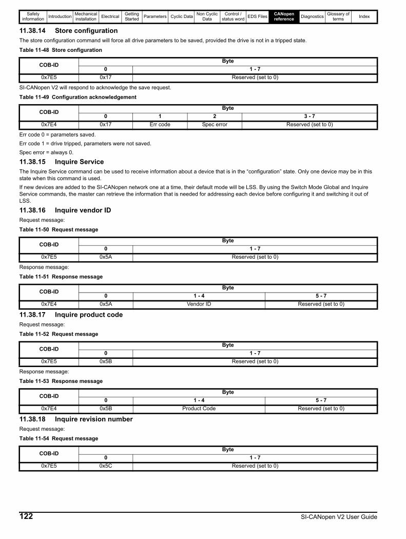
Safety information Introduction Mechanical
installation Electrical Getting Started Parameters Cyclic Data Non Cyclic
DataControl /
status word EDS Files CANopen reference Diagnostics Glossary of
terms Index
11.38.14 Store configurationThe store configuration command will force all drive parameters to be saved, provided the drive is not in a tripped state.
SI-CANopen V2 will respond to acknowledge the save request.
Err code 0 = parameters saved.Err code 1 = drive tripped, parameters were not saved.Spec error = always 0.
11.38.15 Inquire ServiceThe Inquire Service command can be used to receive information about a device that is in the “configuration” state. Only one device may be in this state when this command is used.If new devices are added to the SI-CANopen network one at a time, their default mode will be LSS. By using the Switch Mode Global and Inquire Service commands, the master can retrieve the information that is needed for addressing each device before configuring it and switching it out of LSS.
11.38.16 Inquire vendor IDRequest message:
Response message:
11.38.17 Inquire product codeRequest message:
Response message:
11.38.18 Inquire revision numberRequest message:
Table 11-48 Store configuration
COB-IDByte
0 1 - 70x7E5 0x17 Reserved (set to 0)
Table 11-49 Configuration acknowledgement
COB-IDByte
0 1 2 3 - 70x7E4 0x17 Err code Spec error Reserved (set to 0)
Table 11-50 Request message
COB-IDByte
0 1 - 70x7E5 0x5A Reserved (set to 0)
Table 11-51 Response message
COB-IDByte
0 1 - 4 5 - 70x7E4 0x5A Vendor ID Reserved (set to 0)
Table 11-52 Request message
COB-IDByte
0 1 - 70x7E5 0x5B Reserved (set to 0)
Table 11-53 Response message
COB-IDByte
0 1 - 4 5 - 70x7E4 0x5B Product Code Reserved (set to 0)
Table 11-54 Request message
COB-IDByte
0 1 - 70x7E5 0x5C Reserved (set to 0)
122 SI-CANopen V2 User Guide
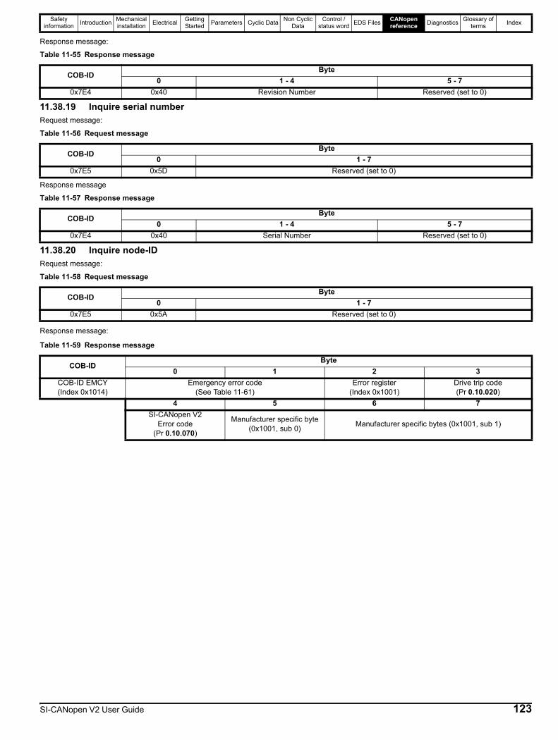
Safety information Introduction Mechanical
installation Electrical Getting Started Parameters Cyclic Data Non Cyclic
DataControl /
status word EDS Files CANopen reference Diagnostics Glossary of
terms Index
Response message:
11.38.19 Inquire serial numberRequest message:
Response message
11.38.20 Inquire node-IDRequest message:
Response message:
Table 11-55 Response message
COB-IDByte
0 1 - 4 5 - 70x7E4 0x40 Revision Number Reserved (set to 0)
Table 11-56 Request message
COB-IDByte
0 1 - 70x7E5 0x5D Reserved (set to 0)
Table 11-57 Response message
COB-IDByte
0 1 - 4 5 - 70x7E4 0x40 Serial Number Reserved (set to 0)
Table 11-58 Request message
COB-IDByte
0 1 - 70x7E5 0x5A Reserved (set to 0)
Table 11-59 Response message
COB-IDByte
0 1 2 3COB-ID EMCY(Index 0x1014)
Emergency error code(See Table 11-61)
Error register(Index 0x1001)
Drive trip code(Pr 0.10.020)
4 5 6 7SI-CANopen V2
Error code(Pr 0.10.070)
Manufacturer specific byte (0x1001, sub 0) Manufacturer specific bytes (0x1001, sub 1)
SI-CANopen V2 User Guide 123

Safety information Introduction Mechanical
installation Electrical Getting Started Parameters Cyclic Data Non Cyclic
DataControl /
status word EDS Files CANopen reference Diagnostics Glossary of
terms Index
11.39 0x1014 - Emergency object11.39.1 What is the emergency object?Emergency objects are transmitted by the SI-CANopen V2 when it detects that the drive has tripped. They are high priority messages that inform the CANopen master controller that some sort of error has occurred. It is up to the CANopen master controller to take appropriate action.Emergency objects are suitable for interrupt-type error alerts. An emergency object is transmitted only once per error event and provided that no new errors occur, no further emergency objects will be transmitted.
11.39.2 Emergency object formatThe emergency object consists of a total of eight data bytes. The first 3 bytes are defined by the CANopen specification, and the remaining five bytes are manufacturer-specific.SI-CANopen V2 will return the drive trip code and the SI-CANopen V2 error code, allowing the CANopen master controller to determine exactly what fault has occurred.Bytes 5 to 7 are always transmitted, but will always be set to 0.
The CANopen specification defines a list of standard error codes. Supported CANopen emergency error codes (and the drive trips that will produce the emergency error code) are listed in Table 11-61. All other drive trips will produce the generic error code, 0x1000.
Table 11-61 Emergency error codes
Table 11-60 Emergency object format
COB-IDByte
0 1 2 3 4COB-ID EMCY(Index 0x1014)
Emergency error code(See Table 11-61)
Error register (Index 0x1001)
Drive trip code(Pr 0.10.020)
CANopen error(Pr 0.10.070)
Error Category Error CodeDrive Trip Code
Trip NameM7XX M2XX/M4XX
C200/C300Error reset / No error 0x0000 - - None
Short circuit / earth leakage(Device)
0x22305 PSU
9 - PSU_24V92 OI_SNUBBER
Short circuit(Motor)
0x2340 3 OI_AC
Phase failure 0x313032 PHASE_LOSS98 OUT_PHASE_LOSS
198 -DC link over-voltage 0x3210 2 OVER_VOLTS
Load error 0x3230 38 - LOW_LOAD
Excess temperature
0x4310 21 OHT_INVERTER0x4311 22 OHT_POWER0x4312 23 219 OHT_CONTROL0x4313 24 THERMISTOR0x4314 27 OHT_DC_BUS0x4315 101 - OHT_BRAKE0x431F S.213 OHT_OPTION_MODULE
Control device hardware
0x5112 91 - USER_24V0x5200 200 SLOT1_HF0x5201 203 SLOT1_NOT_FITTED0x5202 204 SLOT1_DIFFERENT0x5203 205 - SLOT2_HF0x5204 208 - SLOT2_NOT_FITTED0x5205 209 - SLOT2_DIFFERENT0x5206 210 - SLOT3_HF0x5207 213 - SLOT3_NOT_FITTED0x5208 214 - SLOT3_DIFFERENT0x5209 250 - SLOT4_HF0x520A 253 - SLOT4_NOT_FITTED0x520B 254 - SLOT4_DIFFERENT
124 SI-CANopen V2 User Guide

Safety information Introduction Mechanical
installation Electrical Getting Started Parameters Cyclic Data Non Cyclic
DataControl /
status word EDS Files CANopen reference Diagnostics Glossary of
terms Index
Error Category Error CodeDrive Trip Code
Trip NameM7XX M2XX/M4XX
C200/C300
Power section 0x5400111 - CONFIGURATION
220 POWER_DATA223 - RATING_MISMATCH
Input stages 0x5430 94 - RECTIFIER_SETUPContacts 0x5440 226 SOFT_START
RAM 0x5510 227 - SUB_ARRAY_RAM
Data storage(Non-volatile data memory)
0x553031 EEPROM_FAIL36 USER_SAVE37 POWER_DOWN_SAVE
Software reset (watchdog) 0x6010 30 WATCHDOG
Parameter error 0x6320199 DESTINATION
216 - SLOT_APP_MENU217 - APP_MENU_CHANGED
Brake chopper over-current 0x71124 OI_BRAKE
19 BRAKE_R_TOO_HOTProtective circuit brake chopper 0x7113 10 - TH_BRAKE_RES
Motor 0x712011 AUTOTUNE_1
12 - AUTOTUNE_213 - AUTOTUNE_3
Motor or commutation error 0x7122
14 - AUTOTUNE_415 - AUTOTUNE_516 - AUTOTUNE_620 - MOTOR_TOO_HOT
25 TH_SHORT_CIRCUIT33 RESISTANCE
Sensor 0x7300
17 - AUTOTUNE_7162 - ENCODER_12163 - ENCODER_13176 - NAME_PLATE189 - ENCODER_1190 - ENCODER_2191 - ENCODER_3192 - ENCODER_4193 - ENCODER_5194 - ENCODER_6195 - ENCODER_7196 - ENCODER_8197 - ENCODER_9
218 TEMP_FEEDBACKSensor (speed) 0x7310 7 OVER_SPEED
Communication 0x750090 93 POWER_COMMS
103 - INTER_CONNECT
SI-CANopen V2 User Guide 125

Safety information Introduction Mechanical
installation Electrical Getting Started Parameters Cyclic Data Non Cyclic
DataControl /
status word EDS Files CANopen reference Diagnostics Glossary of
terms Index
The object 0x603F is automatically cleared when the fault condition is reset.For full details about each trip, refer to the drive documentation.Error register (byte 2)The error register byte contains the current Error Register object (0x1001) value and is used by the SI-CANopen V2 to indicate that an error has occurred, and can be mapped to TxPDOs if required. If a bit is set to 1, the specified error has occurred according to the following table.Table 11-62 Error register byte
Drive trip code (byte 3)The drive trip code byte contains the current value of the last stored trip code in Pr 0.10.020.In the event that the drive is in the under-voltage (UU) state, this byte will contain the value 0x01 as the UU state is not stored as a trip.For more details on the drive trips please refer to the relevant drive documentation.Slot error code (byte 4)In the case of a slot error trip (SL.x.Er) this byte contains the error code from the relevant slot.For more details on the option module errors please refer to the relevant option module documentation.Associated Emergency TriggeringUsing the object association it is possible to trigger Emergency Messages from DPL code within the SI-Applications module. An association must be made to Error Register object (0x1001) sub-index 0, this should be a 32-bit read-only association. When Inter option association is enabled this will be polled in the background task and used to trigger the emergency handler.The object is formatted as follows.
Error Category Error CodeDrive Trip Code
Trip NameM7XX M2XX/M4XX
C200/C300
Data storage
0x7600 174 - CARD_SLOT0x7601 175 CARD_PRODUCT0x7603 177 - CARD_USER_PROG0x7604 178 CARD_BUSY0x7605 179 CARD_DATA_EXISTS0x7606 180 CARD_OPTIONS0x7607 181 CARD_READ_ONLY0x7608 182 CARD_ERROR0x7609 183 CARD_NO_DATA0x760A 184 CARD_FULL0x760B 185 CARD_FILE_ERROR0x760C 186 CARD_RATING0x760D 187 - CARD_FILE_DATA0x760E 188 - CARD_DERIVATIVE
General communication errors(Drive trip)
0x8101
Option module specific0x81020x81030x81040x8105
General communication errors(No drive trip)
0x8606 PDO loss0x8607 Network link loss0x8608 Drive control by the CiA 402 profile disabled
Manufacturer specific 0xFF01 Any trip code not listed
Bit Name Descriptionb0 Generic error Set if any other bits in the register are setb1 Current Set if a current error has occurredb2 Voltage Set when the drive is in the under-voltage (UU) stateb3 Temperature Set if a temperature error has occurredb4
Reserved Always set to 0b5b6b7 Manufacturer specific Set if Pr 0.10.019 is set
MSB LSBReserved User specific Slot Error Drive Trip Error Reg Error Code
126 SI-CANopen V2 User Guide

Safety information Introduction Mechanical
installation Electrical Getting Started Parameters Cyclic Data Non Cyclic
DataControl /
status word EDS Files CANopen reference Diagnostics Glossary of
terms Index
A change of the error code will cause the emergency object error handler to trigger. The emergency object will be formatted as normal, but containing the error code specified in the associated object. The error register value will be a logical “OR” with the value produced by the emergency handler in the module. The user specific byte will be placed in the 5th manufacturer specific byte of the emergency object.For the error-free (all zeros) emergency object to be transmitted, both the emergency handler in the module and the associated object must signify the error is cleared.
11.40 Emergency object stateThe SI-CANopen V2 may be in one of two emergency states, as shown in Figure 11-2.Figure 11-2 Emergency object states
Table 11-63 Emergency object state transitions
Transition Reference Description
0 Initialisation After initialisation, SI-CANopen V2 enters the error free state if no error is detected. The emergency object is not transmitted.
1 Error occurred SI-CANopen V2 detects an error, transmits the emergency object once, and enters the error state.
2 Reset, new error occurred One error (but not all errors) have been cleared. SI-CANopen V2 will transmit another emergency object with information about the remaining error.
3 New error occurred SI-CANopen V2 has detected a new error condition, while in the error state. SI-CANopen V2 remains in error state and transmits another emergency object with the appropriate error codes.
4 Reset, error cleared All errors have been cleared. SI-CANopen V2 will return to the error free state, and transmit an emergency object with the emergency error code set to 0x0000.
Error free
Error occurred
0
1 4
2
3
SI-CANopen V2 User Guide 127

Safety information Introduction Mechanical
installation Electrical Getting Started Parameters Cyclic Data Non Cyclic
DataControl /
status word EDS Files CANopen reference Diagnostics Glossary of
terms Index
11.41 Device profilesThis section details the supported CiA 402 device profiles and the supporting objects.In addition to the basic position mode operation, the following CiA 402 device profiles are supported in SI-CANopen V2:• Profile torque mode• Velocity mode• Homing mode• Profile Position (CiA 402 mode only - Pr S.01.021 = CIA 402 Profile)
11.41.1 Conversion factorsThe velocity mode profile specifies velocity parameters in rpm or percent, time parameters in seconds, and ramps in rpm/second. The drive uses different units for the different types of parameter, so conversion factors must be used.
Hz/rpm functionsThe Hz/rpm functions are used when the drive is in open loop mode, as all speed reference parameters within the drive have units of Hz. The number of motor pole pairs is read from the drive whenever these equations are used.
Hz = rpm x PolePairs / 60rpm = Hz x 60 / PolePairs
Ramp conversion functionsThe ramp conversion functions are used to convert between rpm/s (specified using DeltaSpeed and DeltaTime) and the ramp specification used by the drive.In open loop and SE mode, drive ramp units are specified in s/100 Hz.
Secs / 100 Hz = DeltaTime x (100 x 6 / PolePairs) x 100 / DeltaSpeedIn closed loop and servo modes, drive ramp units are specified in s/1000 rpm.
Secs / 1000 rpm = DeltaTime x 1000 x 1000 / DeltaSpeed
11.41.2 Parameter data object mappingThe control word and status word used by the device profile modes are not the standard drive control and status words. They are defined in CiA DSP-402 V1.1, “Device Profile for Drive and Motion Control”.
11.41.3 Profile torque mode PDO mappingWhen the profile torque mode is selected, RxPDO5 and TxPDO5 consist of two 16-bit words. The specified mappings for profile torque mode are shown in Table 11-64.
11.41.4 Velocity mode PDO mappingWhen the velocity mode profile is selected, RxPDO6 and TxPDO6 consists of two 16-bit words. The specified mappings for velocity mode are shown in Table 11-65.
Table 11-64 PDO5 mapping
Data word Mapped object Mapped object nameRxPDO5 Word 0 0x6040 Control wordRxPDO5 Word 1 0x6071 Target torqueTxPDO5 Word 0 0x6041 Status wordTxPDO5 Word 1 0x6077 Torque actual value
Table 11-65 PDO6 mapping
Data word Mapped object Mapping statusRxPDO6 Word 0 0x6040 Control wordRxPDO6 Word 1 0x6042 VL target velocityTxPDO6 Word 0 0x6041 Status wordTxPDO6 Word 1 0x6044 VL control effort
128 SI-CANopen V2 User Guide
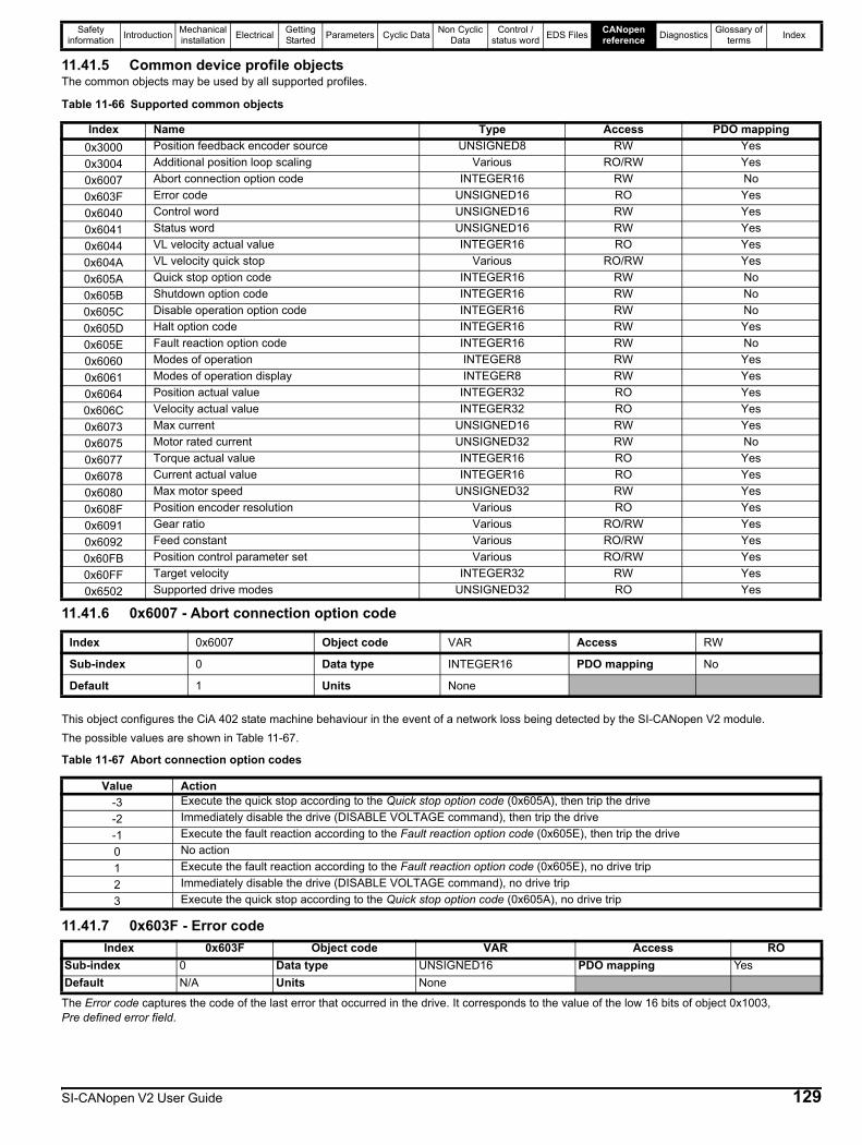
Safety information Introduction Mechanical
installation Electrical Getting Started Parameters Cyclic Data Non Cyclic
DataControl /
status word EDS Files CANopen reference Diagnostics Glossary of
terms Index
11.41.5 Common device profile objectsThe common objects may be used by all supported profiles.
Table 11-66 Supported common objects
11.41.6 0x6007 - Abort connection option code
This object configures the CiA 402 state machine behaviour in the event of a network loss being detected by the SI-CANopen V2 module.The possible values are shown in Table 11-67.
Table 11-67 Abort connection option codes
11.41.7 0x603F - Error code
The Error code captures the code of the last error that occurred in the drive. It corresponds to the value of the low 16 bits of object 0x1003, Pre defined error field.
Index Name Type Access PDO mapping0x3000 Position feedback encoder source UNSIGNED8 RW Yes0x3004 Additional position loop scaling Various RO/RW Yes0x6007 Abort connection option code INTEGER16 RW No0x603F Error code UNSIGNED16 RO Yes0x6040 Control word UNSIGNED16 RW Yes0x6041 Status word UNSIGNED16 RW Yes0x6044 VL velocity actual value INTEGER16 RO Yes0x604A VL velocity quick stop Various RO/RW Yes0x605A Quick stop option code INTEGER16 RW No0x605B Shutdown option code INTEGER16 RW No0x605C Disable operation option code INTEGER16 RW No0x605D Halt option code INTEGER16 RW Yes0x605E Fault reaction option code INTEGER16 RW No0x6060 Modes of operation INTEGER8 RW Yes0x6061 Modes of operation display INTEGER8 RW Yes0x6064 Position actual value INTEGER32 RO Yes0x606C Velocity actual value INTEGER32 RO Yes0x6073 Max current UNSIGNED16 RW Yes0x6075 Motor rated current UNSIGNED32 RW No0x6077 Torque actual value INTEGER16 RO Yes0x6078 Current actual value INTEGER16 RO Yes0x6080 Max motor speed UNSIGNED32 RW Yes0x608F Position encoder resolution Various RO Yes0x6091 Gear ratio Various RO/RW Yes0x6092 Feed constant Various RO/RW Yes0x60FB Position control parameter set Various RO/RW Yes0x60FF Target velocity INTEGER32 RW Yes0x6502 Supported drive modes UNSIGNED32 RO Yes
Index 0x6007 Object code VAR Access RW
Sub-index 0 Data type INTEGER16 PDO mapping No
Default 1 Units None
Value Action-3 Execute the quick stop according to the Quick stop option code (0x605A), then trip the drive-2 Immediately disable the drive (DISABLE VOLTAGE command), then trip the drive-1 Execute the fault reaction according to the Fault reaction option code (0x605E), then trip the drive0 No action1 Execute the fault reaction according to the Fault reaction option code (0x605E), no drive trip2 Immediately disable the drive (DISABLE VOLTAGE command), no drive trip3 Execute the quick stop according to the Quick stop option code (0x605A), no drive trip
Index 0x603F Object code VAR Access ROSub-index 0 Data type UNSIGNED16 PDO mapping YesDefault N/A Units None
SI-CANopen V2 User Guide 129
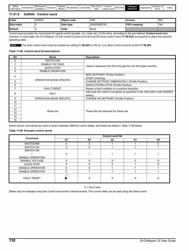
Safety information Introduction Mechanical
installation Electrical Getting Started Parameters Cyclic Data Non Cyclic
DataControl /
status word EDS Files CANopen reference Diagnostics Glossary of
terms Index
11.41.8 0x6040 - Control word
Control word provides the commands for logical control (enable, run, reset, etc.) of the drive, according to the pre-defined Control word state machine. In each state, the SI-CANopen V2 will convert Control word and set the drive control word (Pr 06.042) as required to attain the required operating state.
Table 11-68 Control word bit descriptions
Seven device commands are used to switch between different control states, and these are listed in Table 11-69 below.
Table 11-69 Example control words
X = Don’t careStates may be changed using the Control word and/or internal events. The current state can be read using the Status word.
Index 0x6040 Object code VAR Access RW
Sub-index 0 Data type UNSIGNED16 PDO mapping Yes
Default 0 Units None
The drive control word must be enabled by setting Pr 06.043 to ON (or 1) to allow Control word to control Pr 06.042.
Bit Name Description0 SWITCH ON
Used to sequence the drive through the CiA 402 state machine1 ENABLE VOLTAGE2 QUICK STOP3 ENABLE OPERATION
4OPERATION MODE SPECIFIC
NEW SETPOINT (Profile Position)START (Homing)
5 CHANGE SETPOINT IMMEDIATELY (Profile Position)6 ABSOLUTE/RELATIVE (Profile Position)7 FAULT RESET Resets a fault condition on a positive transition
8 HALTInterrupts the motion in progress as specified in the Halt option code (0x605D) setting
9 OPERATION MODE SPECIFIC CHANGE ON SETPOINT (Profile Position)10
Reserved These bits are reserved for future use
1112131415
NOTE
CommandControl word bit
b7 b3 b2 b1 b0SHUTDOWN 0 0 1 1 0SWITCH ON 0 0 1 1 1SWITCH ON
+ENABLE OPERATION
0 1 1 1 1
DISABLE VOLTAGE 0 X X 0 XQUICK STOP 0 X 0 1 X
DISABLE OPERATION 0 0 1 1 1ENABLE OPERATION 0 1 1 1 1
FAULT RESET X X X X
130 SI-CANopen V2 User Guide
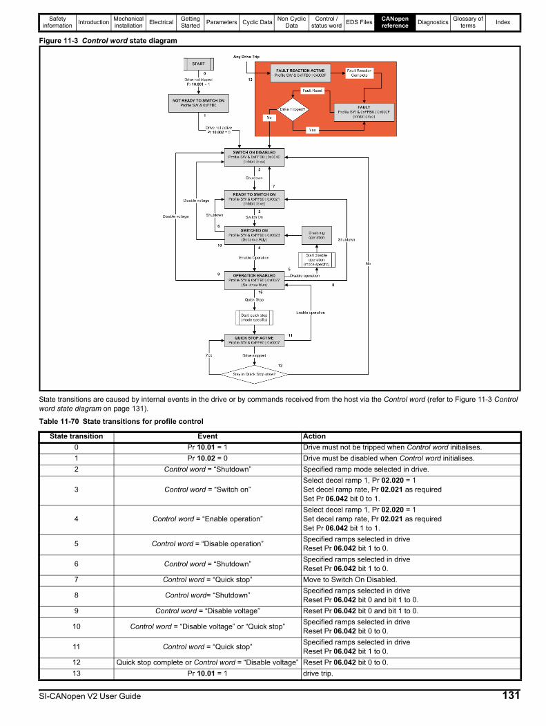
Safety information Introduction Mechanical
installation Electrical Getting Started Parameters Cyclic Data Non Cyclic
DataControl /
status word EDS Files CANopen reference Diagnostics Glossary of
terms Index
Figure 11-3 Control word state diagram
State transitions are caused by internal events in the drive or by commands received from the host via the Control word (refer to Figure 11-3 Control word state diagram on page 131).
Table 11-70 State transitions for profile control
State transition Event Action0 Pr 10.01 = 1 Drive must not be tripped when Control word initialises.1 Pr 10.02 = 0 Drive must be disabled when Control word initialises.2 Control word = “Shutdown” Specified ramp mode selected in drive.
3 Control word = “Switch on”Select decel ramp 1, Pr 02.020 = 1Set decel ramp rate, Pr 02.021 as requiredSet Pr 06.042 bit 0 to 1.
4 Control word = “Enable operation”Select decel ramp 1, Pr 02.020 = 1Set decel ramp rate, Pr 02.021 as requiredSet Pr 06.042 bit 1 to 1.
5 Control word = “Disable operation” Specified ramps selected in driveReset Pr 06.042 bit 1 to 0.
6 Control word = “Shutdown” Specified ramps selected in driveReset Pr 06.042 bit 1 to 0.
7 Control word = “Quick stop” Move to Switch On Disabled.
8 Control word= “Shutdown” Specified ramps selected in driveReset Pr 06.042 bit 0 and bit 1 to 0.
9 Control word = “Disable voltage” Reset Pr 06.042 bit 0 and bit 1 to 0.
10 Control word = “Disable voltage” or “Quick stop” Specified ramps selected in driveReset Pr 06.042 bit 0 to 0.
11 Control word = “Quick stop” Specified ramps selected in driveReset Pr 06.042 bit 1 to 0.
12 Quick stop complete or Control word = “Disable voltage” Reset Pr 06.042 bit 0 to 0.13 Pr 10.01 = 1 drive trip.
SI-CANopen V2 User Guide 131
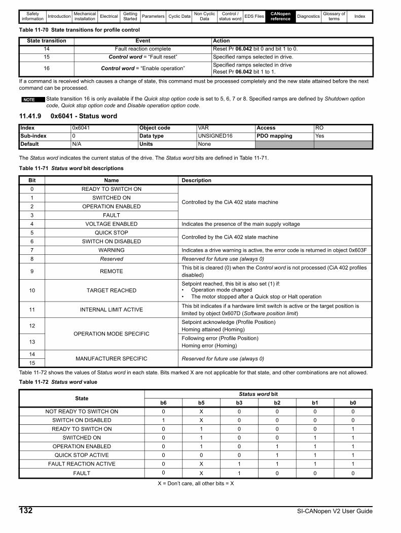
Safety information Introduction Mechanical
installation Electrical Getting Started Parameters Cyclic Data Non Cyclic
DataControl /
status word EDS Files CANopen reference Diagnostics Glossary of
terms Index
If a command is received which causes a change of state, this command must be processed completely and the new state attained before the next command can be processed.
11.41.9 0x6041 - Status word
The Status word indicates the current status of the drive. The Status word bits are defined in Table 11-71.
Table 11-72 shows the values of Status word in each state. Bits marked X are not applicable for that state, and other combinations are not allowed.
X = Don’t care, all other bits = X
14 Fault reaction complete Reset Pr 06.042 bit 0 and bit 1 to 0.15 Control word = “Fault reset” Specified ramps selected in drive.
16 Control word = “Enable operation” Specified ramps selected in driveReset Pr 06.042 bit 1 to 1.
Table 11-70 State transitions for profile control
State transition Event Action
State transition 16 is only available if the Quick stop option code is set to 5, 6, 7 or 8. Specified ramps are defined by Shutdown option code, Quick stop option code and Disable operation option code.
Index 0x6041 Object code VAR Access ROSub-index 0 Data type UNSIGNED16 PDO mapping YesDefault N/A Units None
NOTE
Table 11-71 Status word bit descriptions
Bit Name Description0 READY TO SWITCH ON
Controlled by the CiA 402 state machine1 SWITCHED ON2 OPERATION ENABLED3 FAULT4 VOLTAGE ENABLED Indicates the presence of the main supply voltage5 QUICK STOP
Controlled by the CiA 402 state machine6 SWITCH ON DISABLED7 WARNING Indicates a drive warning is active, the error code is returned in object 0x603F8 Reserved Reserved for future use (always 0)
9 REMOTEThis bit is cleared (0) when the Control word is not processed (CiA 402 profiles disabled)
10 TARGET REACHEDSetpoint reached, this bit is also set (1) if:• Operation mode changed• The motor stopped after a Quick stop or Halt operation
11 INTERNAL LIMIT ACTIVEThis bit indicates if a hardware limit switch is active or the target position is limited by object 0x607D (Software position limit)
12OPERATION MODE SPECIFIC
Setpoint acknowledge (Profile Position)Homing attained (Homing)
13Following error (Profile Position)Homing error (Homing)
14MANUFACTURER SPECIFIC Reserved for future use (always 0)
15
Table 11-72 Status word value
StateStatus word bit
b6 b5 b3 b2 b1 b0NOT READY TO SWITCH ON 0 X 0 0 0 0
SWITCH ON DISABLED 1 X 0 0 0 0READY TO SWITCH ON 0 1 0 0 0 1
SWITCHED ON 0 1 0 0 1 1OPERATION ENABLED 0 1 0 1 1 1QUICK STOP ACTIVE 0 0 0 1 1 1
FAULT REACTION ACTIVE 0 X 1 1 1 1
FAULT 0 X 1 0 0 0
132 SI-CANopen V2 User Guide
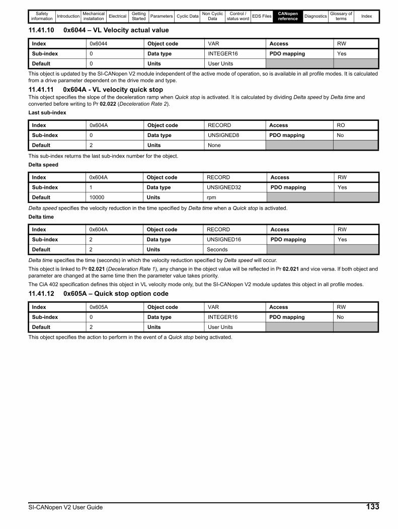
Safety information Introduction Mechanical
installation Electrical Getting Started Parameters Cyclic Data Non Cyclic
DataControl /
status word EDS Files CANopen reference Diagnostics Glossary of
terms Index
11.41.10 0x6044 – VL Velocity actual value
This object is updated by the SI-CANopen V2 module independent of the active mode of operation, so is available in all profile modes. It is calculated from a drive parameter dependent on the drive mode and type.
11.41.11 0x604A - VL velocity quick stopThis object specifies the slope of the deceleration ramp when Quick stop is activated. It is calculated by dividing Delta speed by Delta time and converted before writing to Pr 02.022 (Deceleration Rate 2).Last sub-index
This sub-index returns the last sub-index number for the object.Delta speed
Delta speed specifies the velocity reduction in the time specified by Delta time when a Quick stop is activated.Delta time
Delta time specifies the time (seconds) in which the velocity reduction specified by Delta speed will occur.This object is linked to Pr 02.021 (Deceleration Rate 1), any change in the object value will be reflected in Pr 02.021 and vice versa. If both object and parameter are changed at the same time then the parameter value takes priority.The CiA 402 specification defines this object in VL velocity mode only, but the SI-CANopen V2 module updates this object in all profile modes.
11.41.12 0x605A – Quick stop option code
This object specifies the action to perform in the event of a Quick stop being activated.
Index 0x6044 Object code VAR Access RW
Sub-index 0 Data type INTEGER16 PDO mapping Yes
Default 0 Units User Units
Index 0x604A Object code RECORD Access RO
Sub-index 0 Data type UNSIGNED8 PDO mapping No
Default 2 Units None
Index 0x604A Object code RECORD Access RW
Sub-index 1 Data type UNSIGNED32 PDO mapping Yes
Default 10000 Units rpm
Index 0x604A Object code RECORD Access RW
Sub-index 2 Data type UNSIGNED16 PDO mapping Yes
Default 2 Units Seconds
Index 0x605A Object code VAR Access RW
Sub-index 0 Data type INTEGER16 PDO mapping No
Default 2 Units User Units
SI-CANopen V2 User Guide 133
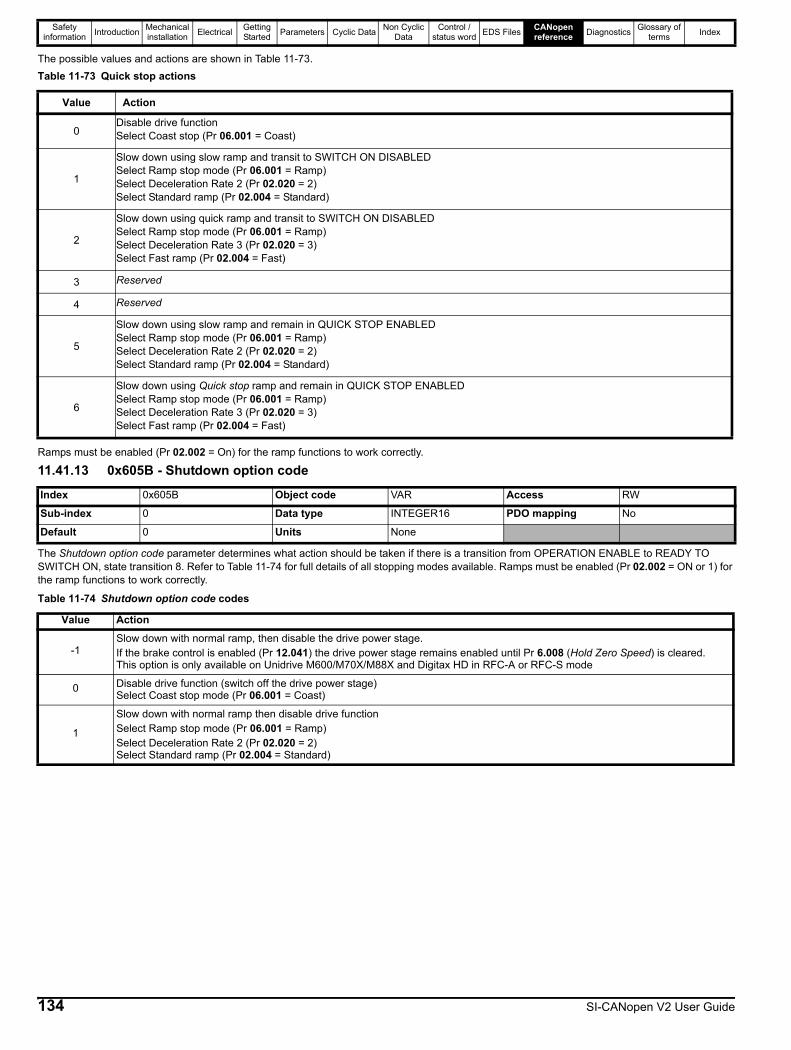
Safety information Introduction Mechanical
installation Electrical Getting Started Parameters Cyclic Data Non Cyclic
DataControl /
status word EDS Files CANopen reference Diagnostics Glossary of
terms Index
The possible values and actions are shown in Table 11-73.Table 11-73 Quick stop actions
Ramps must be enabled (Pr 02.002 = On) for the ramp functions to work correctly.
11.41.13 0x605B - Shutdown option code
The Shutdown option code parameter determines what action should be taken if there is a transition from OPERATION ENABLE to READY TO SWITCH ON, state transition 8. Refer to Table 11-74 for full details of all stopping modes available. Ramps must be enabled (Pr 02.002 = ON or 1) for the ramp functions to work correctly.
Value Action
0Disable drive functionSelect Coast stop (Pr 06.001 = Coast)
1
Slow down using slow ramp and transit to SWITCH ON DISABLEDSelect Ramp stop mode (Pr 06.001 = Ramp)Select Deceleration Rate 2 (Pr 02.020 = 2)Select Standard ramp (Pr 02.004 = Standard)
2
Slow down using quick ramp and transit to SWITCH ON DISABLEDSelect Ramp stop mode (Pr 06.001 = Ramp)Select Deceleration Rate 3 (Pr 02.020 = 3)Select Fast ramp (Pr 02.004 = Fast)
3 Reserved
4 Reserved
5
Slow down using slow ramp and remain in QUICK STOP ENABLEDSelect Ramp stop mode (Pr 06.001 = Ramp)Select Deceleration Rate 2 (Pr 02.020 = 2)Select Standard ramp (Pr 02.004 = Standard)
6
Slow down using Quick stop ramp and remain in QUICK STOP ENABLEDSelect Ramp stop mode (Pr 06.001 = Ramp)Select Deceleration Rate 3 (Pr 02.020 = 3)Select Fast ramp (Pr 02.004 = Fast)
Index 0x605B Object code VAR Access RW
Sub-index 0 Data type INTEGER16 PDO mapping No
Default 0 Units None
Table 11-74 Shutdown option code codes
Value Action
-1Slow down with normal ramp, then disable the drive power stage.If the brake control is enabled (Pr 12.041) the drive power stage remains enabled until Pr 6.008 (Hold Zero Speed) is cleared.This option is only available on Unidrive M600/M70X/M88X and Digitax HD in RFC-A or RFC-S mode
0 Disable drive function (switch off the drive power stage)Select Coast stop mode (Pr 06.001 = Coast)
1
Slow down with normal ramp then disable drive functionSelect Ramp stop mode (Pr 06.001 = Ramp)Select Deceleration Rate 2 (Pr 02.020 = 2)Select Standard ramp (Pr 02.004 = Standard)
134 SI-CANopen V2 User Guide
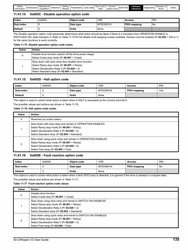
Safety information Introduction Mechanical
installation Electrical Getting Started Parameters Cyclic Data Non Cyclic
DataControl /
status word EDS Files CANopen reference Diagnostics Glossary of
terms Index
11.41.14 0x605C - Disable operation option code
The Disable operation option code parameter determines what action should be taken if there is a transition from OPERATION ENABLE to SWITCHED ON, state transition 5. Refer to Table 11-75 for full details of all stopping modes available. Ramps must be enabled (Pr 02.002 = ON or 1) for the ramp functions to work correctly.
11.41.15 0x605D - Halt option code
This object is used to control what action is taken when a HALT is requested by the Control word bit 8.The possible values and actions are shown in Table 11-76.Table 11-76 Halt option code codes
11.41.16 0x605E - Fault reaction option code
This object is used to control what action is taken when a fault (PDO loss) is detected, it is ignored if the drive is already in a tripped state.The possible values and actions are shown in Table 11-77.Table 11-77 Fault reaction option code values
Index 0x605C Object code VAR Access RW
Sub-index 0 Data type INTEGER16 PDO mapping No
Default 0 Units None
Table 11-75 Disable operation option code codes
Value Action
0 Disable drive function (switch off the drive power stage)Select Coast stop mode (Pr 06.001 = Coast)
1
Slow down with slow ramp then disable drive functionSelect Ramp stop mode (Pr 06.001 = Ramp)Select Deceleration Rate 2 (Pr 02.020 = 2)Select Standard ramp (Pr 02.004 = Standard)
Index 0x605D Object code VAR Access RW
Sub-index 0 Data type INTEGER16 PDO mapping Yes
Default 0 Units None
Value Action
0 Reserved (no action taken)
1
Slow down with slow ramp and remain in OPERATION ENABLEDSelect Ramp stop mode (Pr 06.001 = Ramp)Select Deceleration Rate 2 (Pr 02.020 = 2)Select Standard ramp (Pr 02.004 = Standard)
2
Slow down using quick ramp and remain in OPERATION ENABLEDSelect Ramp stop mode (Pr 06.001 = Ramp)Select Deceleration Rate 3 (Pr 02.020 = 3)Select Fast ramp (Pr 02.004 = Fast)
Index 0x605E Object code VAR Access RW
Sub-index 0 Data type INTEGER16 PDO mapping No
Default 2 Units None
Value Action
0Disable drive functionSelect Coast stop (Pr 06.001 = Coast)
1
Slow down using slow ramp and transit to SWITCH ON DISABLEDSelect Ramp stop mode (Pr 06.001 = Ramp)Select Deceleration Rate 2 (Pr 02.020 = 2)Select Standard ramp (Pr 02.004 = Standard)
2
Slow down using quick ramp and transit to SWITCH ON DISABLEDSelect Ramp stop mode (Pr 06.001 = Ramp)Select Deceleration Rate 3 (Pr 02.020 = 3)Select Fast ramp (Pr 02.004 = Fast)
SI-CANopen V2 User Guide 135
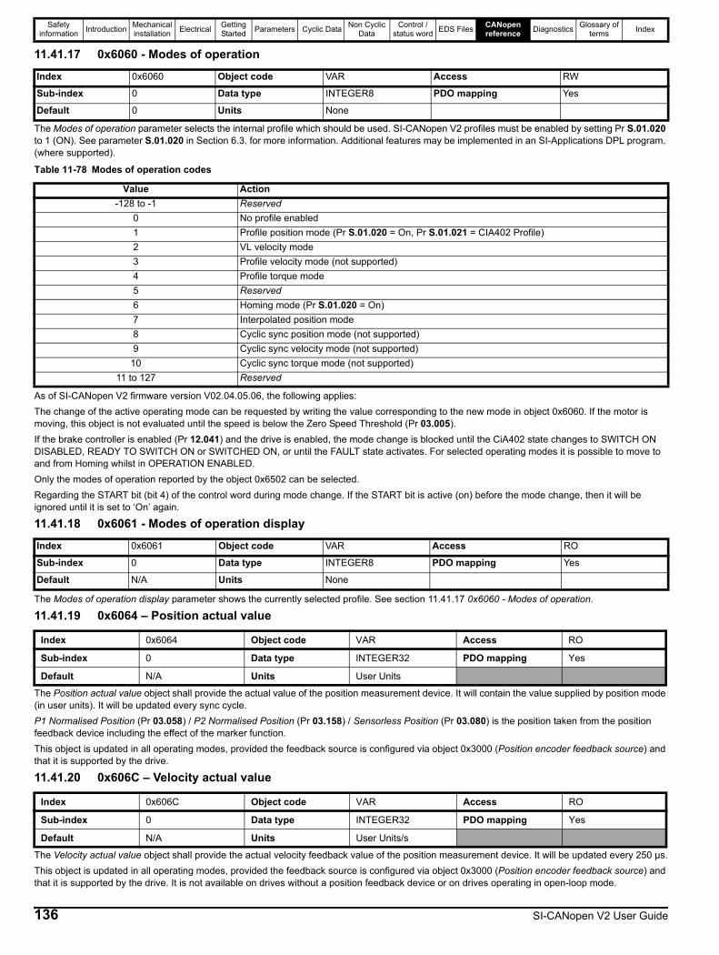
Safety information Introduction Mechanical
installation Electrical Getting Started Parameters Cyclic Data Non Cyclic
DataControl /
status word EDS Files CANopen reference Diagnostics Glossary of
terms Index
11.41.17 0x6060 - Modes of operation
The Modes of operation parameter selects the internal profile which should be used. SI-CANopen V2 profiles must be enabled by setting Pr S.01.020 to 1 (ON). See parameter S.01.020 in Section 6.3. for more information. Additional features may be implemented in an SI-Applications DPL program. (where supported).
As of SI-CANopen V2 firmware version V02.04.05.06, the following applies:The change of the active operating mode can be requested by writing the value corresponding to the new mode in object 0x6060. If the motor is moving, this object is not evaluated until the speed is below the Zero Speed Threshold (Pr 03.005).If the brake controller is enabled (Pr 12.041) and the drive is enabled, the mode change is blocked until the CiA402 state changes to SWITCH ON DISABLED, READY TO SWITCH ON or SWITCHED ON, or until the FAULT state activates. For selected operating modes it is possible to move to and from Homing whilst in OPERATION ENABLED.Only the modes of operation reported by the object 0x6502 can be selected.Regarding the START bit (bit 4) of the control word during mode change. If the START bit is active (on) before the mode change, then it will be ignored until it is set to ‘On’ again.
11.41.18 0x6061 - Modes of operation display
The Modes of operation display parameter shows the currently selected profile. See section 11.41.17 0x6060 - Modes of operation.
11.41.19 0x6064 – Position actual value
The Position actual value object shall provide the actual value of the position measurement device. It will contain the value supplied by position mode (in user units). It will be updated every sync cycle.P1 Normalised Position (Pr 03.058) / P2 Normalised Position (Pr 03.158) / Sensorless Position (Pr 03.080) is the position taken from the position feedback device including the effect of the marker function.This object is updated in all operating modes, provided the feedback source is configured via object 0x3000 (Position encoder feedback source) and that it is supported by the drive.
11.41.20 0x606C – Velocity actual value
The Velocity actual value object shall provide the actual velocity feedback value of the position measurement device. It will be updated every 250 µs.This object is updated in all operating modes, provided the feedback source is configured via object 0x3000 (Position encoder feedback source) and that it is supported by the drive. It is not available on drives without a position feedback device or on drives operating in open-loop mode.
Index 0x6060 Object code VAR Access RW
Sub-index 0 Data type INTEGER8 PDO mapping Yes
Default 0 Units None
Table 11-78 Modes of operation codes
Value Action-128 to -1 Reserved
0 No profile enabled1 Profile position mode (Pr S.01.020 = On, Pr S.01.021 = CIA402 Profile)2 VL velocity mode3 Profile velocity mode (not supported)4 Profile torque mode5 Reserved6 Homing mode (Pr S.01.020 = On)7 Interpolated position mode 8 Cyclic sync position mode (not supported)9 Cyclic sync velocity mode (not supported)
10 Cyclic sync torque mode (not supported)11 to 127 Reserved
Index 0x6061 Object code VAR Access RO
Sub-index 0 Data type INTEGER8 PDO mapping Yes
Default N/A Units None
Index 0x6064 Object code VAR Access RO
Sub-index 0 Data type INTEGER32 PDO mapping Yes
Default N/A Units User Units
Index 0x606C Object code VAR Access RO
Sub-index 0 Data type INTEGER32 PDO mapping Yes
Default N/A Units User Units/s
136 SI-CANopen V2 User Guide

Safety information Introduction Mechanical
installation Electrical Getting Started Parameters Cyclic Data Non Cyclic
DataControl /
status word EDS Files CANopen reference Diagnostics Glossary of
terms Index
11.41.21 0x6073 – Max current
This object specifies the maximum current value in 0.1 % units.e.g. A value of 1000 equates to 100.0 %.This object is linked to Pr 04.007 (Symmetrical Current Limit), any change in the object value will be reflected in Pr 04.007 and vice versa. If both object and parameter are changed at the same time then the parameter value takes priority.This object is initialised with the value of Pr 04.007 on startup.
11.41.22 0x6075 – Motor rated current
This object specifies the motor rated current in mA and is linked to Pr 05.007 (Rated Current).Any change in the object value will be reflected in Pr 05.007 and vice versa. If both object and parameter are changed at the same time then the parameter value takes priority.This object is initialised with the value of Pr 05.007 on startup.
11.41.23 0x6077 – Torque actual value
This object returns the estimated torque value on the motor shaft, it is obtained from the torque producing current represented as a percentage of the rated value for the motor.For a drive operating in open-loop mode, this object value is copied from Pr 04.020 (Percentage Load), in RFC-A mode this object value is copied from Pr 04.003 (Final Torque Reference).
11.41.24 0x6078 - Current actual value
This object indicates the actual instantaneous value of current in 0.1 % units derived from Pr 04.001 (Current Magnitude).e.g. A value of 1000 equates to 100.0 % in Pr 04.001.
11.41.25 0x6080 – Max motor speed
This object indicates the configured maximum allowed motor speed in either direction. It is initialised with the value from Pr 01.006 (Maximum Reference Clamp) after the appropriate conversion factors in the following circumstances:• Startup• CiA 402 profiles re-enabled• Operating mode changedWhen this object is written, the value is copied and converted using the appropriate conversion factors, before being written to Pr 01.006 (Maximum Reference Clamp) and Pr 39.011 (AMC Output Speed Clamp) within 40 ms.This object is not updated if the drive parameters Pr 01.006 or Pr 39.011 are changed after initialisation, users should refrain from changing the parameter values when CiA 402 profiles are enabled.
As of SI-CANopen V2 firmware V02.04.05.06 this object is updated in the background when the value of Pr 01.006 (Maximum Reference Clamp) changes.
Index 0x6073 Object code VAR Access RW
Sub-index 0 Data type UNSIGNED16 PDO mapping Yes
Default <Pr 04.007> Units 0.1 %
Index 0x6075 Object code VAR Access RW
Sub-index 0 Data type UNSIGNED32 PDO mapping No
Default <Pr 05.007> Units mA
Index 0x6077 Object code VAR Access RO
Sub-index 0 Data type INTEGER16 PDO mapping Yes
Default<Pr 04.020>
or<Pr 04.003>
Units 0.1% rated torque
Index 0x6078 Object code VAR Access RO
Sub-index 0 Data type INTEGER16 PDO mapping Yes
Default <Pr 04.001> Units 0.1% rated current
Index 0x6080 Object code VAR Access RW
Sub-index 0 Data type UNSIGNED32 PDO mapping Yes
Default N/A Units User Units/s
NOTE
SI-CANopen V2 User Guide 137
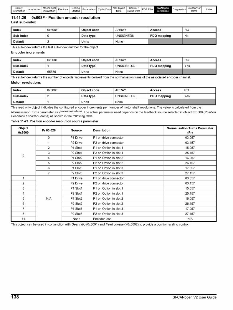
Safety information Introduction Mechanical
installation Electrical Getting Started Parameters Cyclic Data Non Cyclic
DataControl /
status word EDS Files CANopen reference Diagnostics Glossary of
terms Index
11.41.26 0x608F - Position encoder resolutionLast sub-index
This sub-index returns the last sub-index number for the object.
Encoder increments
This sub-index returns the number of encoder increments derived from the normalisation turns of the associated encoder channel.
Motor revolutions
This read only object indicates the configured encoder increments per number of motor shaft revolutions. The value is calculated from the Normalisation Turns parameter as 2NormalisationTurns. The actual parameter used depends on the feedback source selected in object 0x3000 (Position Feedback Encoder Source) as shown in the following table.Table 11-79 Position encoder resolution source parameter
This object can be used in conjunction with Gear ratio (0x6091) and Feed constant (0x6092) to provide a position scaling control.
Index 0x608F Object code ARRAY Access RO
Sub-index 0 Data type UNSIGNED8 PDO mapping No
Default 2 Units None
Index 0x608F Object code ARRAY Access RO
Sub-index 1 Data type UNSIGNED32 PDO mapping Yes
Default 65536 Units None
Index 0x608F Object code ARRAY Access RO
Sub-index 2 Data type UNSIGNED32 PDO mapping Yes
Default 1 Units None
Object 0x3000 Pr 03.026 Source Description Normalisation Turns Parameter
(Pr)
0
0 P1 Drive P1 on drive connector 03.0571 P2 Drive P2 on drive connector 03.1572 P1 Slot1 P1 on Option in slot 1 15.0573 P2 Slot1 P2 on Option in slot 1 25.1574 P1 Slot2 P1 on Option in slot 2 16.0575 P2 Slot2 P2 on Option in slot 2 26.1576 P1 Slot3 P1 on Option in slot 3 17.0577 P2 Slot3 P2 on Option in slot 3 27.157
1
N/A
P1 Drive P1 on drive connector 03.0572 P2 Drive P2 on drive connector 03.1573 P1 Slot1 P1 on Option in slot 1 15.0574 P2 Slot1 P2 on Option in slot 1 25.1575 P1 Slot2 P1 on Option in slot 2 16.0576 P2 Slot2 P2 on Option in slot 2 26.1577 P1 Slot3 P1 on Option in slot 3 17.0578 P2 Slot3 P2 on Option in slot 3 27.157
11 None Encoder less N/A
138 SI-CANopen V2 User Guide
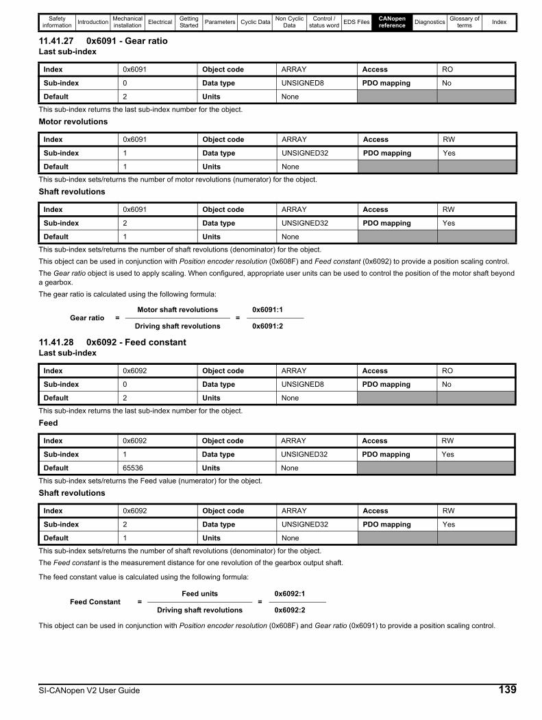
Safety information Introduction Mechanical
installation Electrical Getting Started Parameters Cyclic Data Non Cyclic
DataControl /
status word EDS Files CANopen reference Diagnostics Glossary of
terms Index
11.41.27 0x6091 - Gear ratioLast sub-index
This sub-index returns the last sub-index number for the object.
Motor revolutions
This sub-index sets/returns the number of motor revolutions (numerator) for the object.
Shaft revolutions
This sub-index sets/returns the number of shaft revolutions (denominator) for the object.This object can be used in conjunction with Position encoder resolution (0x608F) and Feed constant (0x6092) to provide a position scaling control.The Gear ratio object is used to apply scaling. When configured, appropriate user units can be used to control the position of the motor shaft beyond a gearbox.The gear ratio is calculated using the following formula:
11.41.28 0x6092 - Feed constantLast sub-index
This sub-index returns the last sub-index number for the object.
Feed
This sub-index sets/returns the Feed value (numerator) for the object.
Shaft revolutions
This sub-index sets/returns the number of shaft revolutions (denominator) for the object.The Feed constant is the measurement distance for one revolution of the gearbox output shaft.
The feed constant value is calculated using the following formula:
This object can be used in conjunction with Position encoder resolution (0x608F) and Gear ratio (0x6091) to provide a position scaling control.
Index 0x6091 Object code ARRAY Access RO
Sub-index 0 Data type UNSIGNED8 PDO mapping No
Default 2 Units None
Index 0x6091 Object code ARRAY Access RW
Sub-index 1 Data type UNSIGNED32 PDO mapping Yes
Default 1 Units None
Index 0x6091 Object code ARRAY Access RW
Sub-index 2 Data type UNSIGNED32 PDO mapping Yes
Default 1 Units None
Gear ratio =Motor shaft revolutions
=0x6091:1
Driving shaft revolutions 0x6091:2
Index 0x6092 Object code ARRAY Access RO
Sub-index 0 Data type UNSIGNED8 PDO mapping No
Default 2 Units None
Index 0x6092 Object code ARRAY Access RW
Sub-index 1 Data type UNSIGNED32 PDO mapping Yes
Default 65536 Units None
Index 0x6092 Object code ARRAY Access RW
Sub-index 2 Data type UNSIGNED32 PDO mapping Yes
Default 1 Units None
Feed Constant =Feed units
=0x6092:1
Driving shaft revolutions 0x6092:2
SI-CANopen V2 User Guide 139
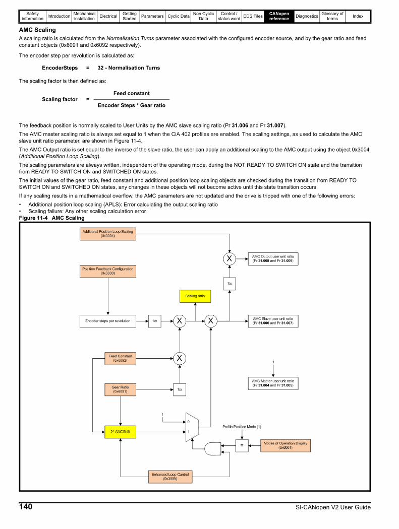
Safety information Introduction Mechanical
installation Electrical Getting Started Parameters Cyclic Data Non Cyclic
DataControl /
status word EDS Files CANopen reference Diagnostics Glossary of
terms Index
AMC ScalingA scaling ratio is calculated from the Normalisation Turns parameter associated with the configured encoder source, and by the gear ratio and feed constant objects (0x6091 and 0x6092 respectively).
The encoder step per revolution is calculated as:
The scaling factor is then defined as:
The feedback position is normally scaled to User Units by the AMC slave scaling ratio (Pr 31.006 and Pr 31.007).The AMC master scaling ratio is always set equal to 1 when the CiA 402 profiles are enabled. The scaling settings, as used to calculate the AMC slave unit ratio parameter, are shown in Figure 11-4.The AMC Output ratio is set equal to the inverse of the slave ratio, the user can apply an additional scaling to the AMC output using the object 0x3004 (Additional Position Loop Scaling).The scaling parameters are always written, independent of the operating mode, during the NOT READY TO SWITCH ON state and the transition from READY TO SWITCH ON and SWITCHED ON states.The initial values of the gear ratio, feed constant and additional position loop scaling objects are checked during the transition from READY TO SWITCH ON and SWITCHED ON states, any changes in these objects will not become active until this state transition occurs.If any scaling results in a mathematical overflow, the AMC parameters are not updated and the drive is tripped with one of the following errors:• Additional position loop scaling (APLS): Error calculating the output scaling ratio• Scaling failure: Any other scaling calculation errorFigure 11-4 AMC Scaling
EncoderSteps = 32 - Normalisation Turns
Scaling factor =Feed constant
Encoder Steps * Gear ratio
140 SI-CANopen V2 User Guide
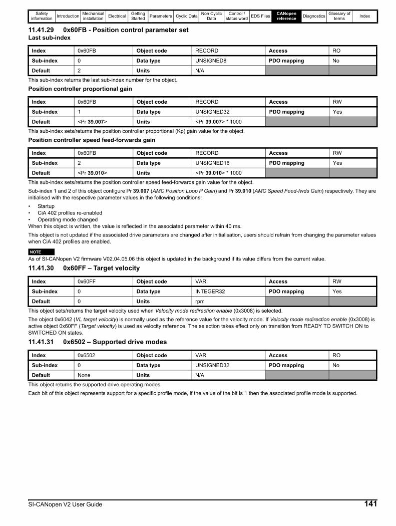
Safety information Introduction Mechanical
installation Electrical Getting Started Parameters Cyclic Data Non Cyclic
DataControl /
status word EDS Files CANopen reference Diagnostics Glossary of
terms Index
11.41.29 0x60FB - Position control parameter setLast sub-index
This sub-index returns the last sub-index number for the object.
Position controller proportional gain
This sub-index sets/returns the position controller proportional (Kp) gain value for the object.
Position controller speed feed-forwards gain
This sub-index sets/returns the position controller speed feed-forwards gain value for the object.Sub-index 1 and 2 of this object configure Pr 39.007 (AMC Position Loop P Gain) and Pr 39.010 (AMC Speed Feed-fwds Gain) respectively. They are initialised with the respective parameter values in the following conditions:• Startup• CiA 402 profiles re-enabled• Operating mode changedWhen this object is written, the value is reflected in the associated parameter within 40 ms.This object is not updated if the associated drive parameters are changed after initialisation, users should refrain from changing the parameter values when CiA 402 profiles are enabled.
As of SI-CANopen V2 firmware V02.04.05.06 this object is updated in the background if its value differs from the current value.
11.41.30 0x60FF – Target velocity
This object sets/returns the target velocity used when Velocity mode redirection enable (0x3008) is selected.The object 0x6042 (VL target velocity) is normally used as the reference value for the velocity mode. If Velocity mode redirection enable (0x3008) is active object 0x60FF (Target velocity) is used as velocity reference. The selection takes effect only on transition from READY TO SWITCH ON to SWITCHED ON states.
11.41.31 0x6502 – Supported drive modes
This object returns the supported drive operating modes.Each bit of this object represents support for a specific profile mode, if the value of the bit is 1 then the associated profile mode is supported.
Index 0x60FB Object code RECORD Access RO
Sub-index 0 Data type UNSIGNED8 PDO mapping No
Default 2 Units N/A
Index 0x60FB Object code RECORD Access RW
Sub-index 1 Data type UNSIGNED32 PDO mapping Yes
Default <Pr 39.007> Units <Pr 39.007> * 1000
Index 0x60FB Object code RECORD Access RW
Sub-index 2 Data type UNSIGNED16 PDO mapping Yes
Default <Pr 39.010> Units <Pr 39.010> * 1000
Index 0x60FF Object code VAR Access RW
Sub-index 0 Data type INTEGER32 PDO mapping Yes
Default 0 Units rpm
Index 0x6502 Object code VAR Access RO
Sub-index 0 Data type UNSIGNED32 PDO mapping No
Default None Units N/A
NOTE
SI-CANopen V2 User Guide 141
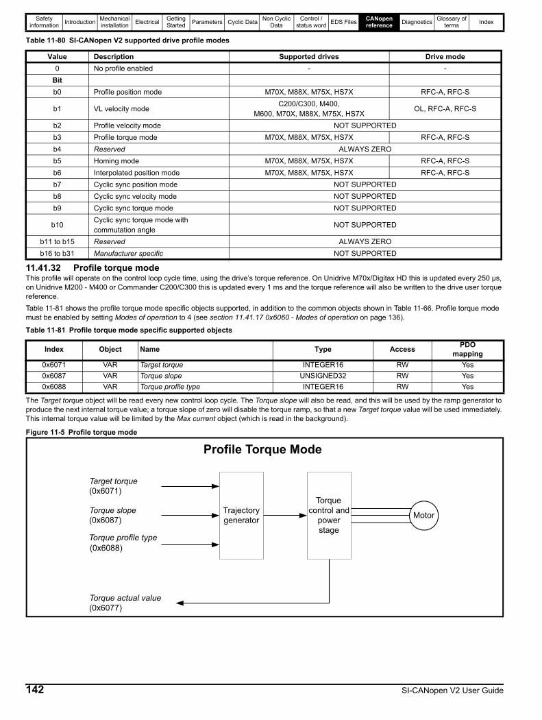
Safety information Introduction Mechanical
installation Electrical Getting Started Parameters Cyclic Data Non Cyclic
DataControl /
status word EDS Files CANopen reference Diagnostics Glossary of
terms Index
Table 11-80 SI-CANopen V2 supported drive profile modes
11.41.32 Profile torque modeThis profile will operate on the control loop cycle time, using the drive’s torque reference. On Unidrive M70x/Digitax HD this is updated every 250 µs, on Unidrive M200 - M400 or Commander C200/C300 this is updated every 1 ms and the torque reference will also be written to the drive user torque reference.Table 11-81 shows the profile torque mode specific objects supported, in addition to the common objects shown in Table 11-66. Profile torque mode must be enabled by setting Modes of operation to 4 (see section 11.41.17 0x6060 - Modes of operation on page 136).
The Target torque object will be read every new control loop cycle. The Torque slope will also be read, and this will be used by the ramp generator to produce the next internal torque value; a torque slope of zero will disable the torque ramp, so that a new Target torque value will be used immediately. This internal torque value will be limited by the Max current object (which is read in the background).
Figure 11-5 Profile torque mode
Value Description Supported drives Drive mode0 No profile enabled - -
Bitb0 Profile position mode M70X, M88X, M75X, HS7X RFC-A, RFC-S
b1 VL velocity modeC200/C300, M400,
M600, M70X, M88X, M75X, HS7XOL, RFC-A, RFC-S
b2 Profile velocity mode NOT SUPPORTEDb3 Profile torque mode M70X, M88X, M75X, HS7X RFC-A, RFC-Sb4 Reserved ALWAYS ZEROb5 Homing mode M70X, M88X, M75X, HS7X RFC-A, RFC-Sb6 Interpolated position mode M70X, M88X, M75X, HS7X RFC-A, RFC-Sb7 Cyclic sync position mode NOT SUPPORTEDb8 Cyclic sync velocity mode NOT SUPPORTEDb9 Cyclic sync torque mode NOT SUPPORTED
b10Cyclic sync torque mode with commutation angle
NOT SUPPORTED
b11 to b15 Reserved ALWAYS ZEROb16 to b31 Manufacturer specific NOT SUPPORTED
Table 11-81 Profile torque mode specific supported objects
Index Object Name Type Access PDOmapping
0x6071 VAR Target torque INTEGER16 RW Yes0x6087 VAR Torque slope UNSIGNED32 RW Yes0x6088 VAR Torque profile type INTEGER16 RW Yes
Profile Torque Mode
Trajectory
generator
Torque actual value
(0x6077)
Torque profile type
(0x6088)
Target torque
(0x6071)
Torque slope
(0x6087)
Torque
control and
power
stage
Motor
142 SI-CANopen V2 User Guide

Safety information Introduction Mechanical
installation Electrical Getting Started Parameters Cyclic Data Non Cyclic
DataControl /
status word EDS Files CANopen reference Diagnostics Glossary of
terms Index
11.41.33 0x6071 - Target torque
Target torque is the input value for the torque controller. This object is multiplied by 100 and written directly to Pr 04.008 when Control word is in the power enabled group of states. Refer to Figure 11-3 on page 131.
11.41.34 0x6086 - Motion profile type
This object is used to configure the velocity profile type used in the Profile Position (PP) mode as shown in the following table
Only the linear and jerk limited ramps are supported, if a non-supported ramp mode is selected, then the linear ramp mode will be used.Please note that when the jerk profile limited ramp profile is used, then the position loop execution period increases from 250 µs to 1 ms.Any changes have effect only in the following cases:
• The mode of operation is changed, and the state is SWITCHED ON or OPERATION ENABLED• State transition from READY TO SWITCH ON to SWITCHED ON• State transition from OPERATION ENABLED to SWITCHED ON• State transition from QUICK STOP ENABLED to OPERATION ENABLED
11.41.35 0x6087 - Torque slope
Torque slope describes the maximum rate of change of torque permitted. When a change in Target torque is seen, SI-CANopen V2 will apply a ramp to the torque reference before updating the torque reference parameter, Pr 04.008.
11.41.36 0x6088 - Torque profile type
The Torque profile type is used to select the type of torque profile used to perform a torque change. Only linear ramps are supported.
Index 0x6071 Object code VAR Access RW
Sub-index 0 Data type INTEGER16 PDOmapping Yes
Default 0 Units per thousand of rated torque
Index 0x6086 Object code VAR Access RW
Sub-index 0 Data type UNISIGNED32 PDOmapping Yes
Default 0 Units None Maximum 3
Value Description0 Linear ramp (trapezoidal profile)1 Not supported2 Not supported3 Jerk limited ramp (s-ramp profile)
Index 0x6087 Object code VAR Access RW
Sub-index 0 Data type UNSIGNED32 PDOmapping Yes
Default 0 Units per thousand of rated torque per second
Index 0x6088 Object code VAR Access RW
Sub-index 0 Data type INTEGER16 PDOmapping Yes
Default 0 Units None
Table 11-82 Torque profile type codes
Profile code Profile type0 Linear ramp (trapezoidal profile)1 Not supported
SI-CANopen V2 User Guide 143
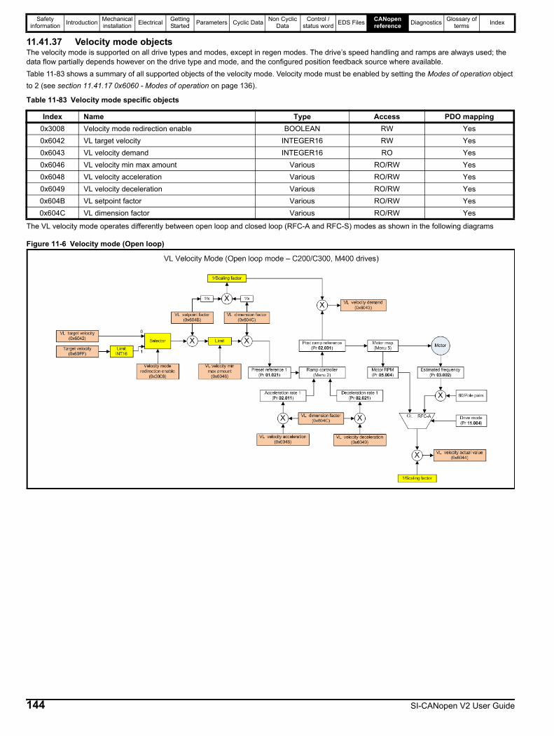
Safety information Introduction Mechanical
installation Electrical Getting Started Parameters Cyclic Data Non Cyclic
DataControl /
status word EDS Files CANopen reference Diagnostics Glossary of
terms Index
11.41.37 Velocity mode objectsThe velocity mode is supported on all drive types and modes, except in regen modes. The drive’s speed handling and ramps are always used; the data flow partially depends however on the drive type and mode, and the configured position feedback source where available.Table 11-83 shows a summary of all supported objects of the velocity mode. Velocity mode must be enabled by setting the Modes of operation object to 2 (see section 11.41.17 0x6060 - Modes of operation on page 136).
The VL velocity mode operates differently between open loop and closed loop (RFC-A and RFC-S) modes as shown in the following diagrams
Figure 11-6 Velocity mode (Open loop)
Table 11-83 Velocity mode specific objects
Index Name Type Access PDO mapping0x3008 Velocity mode redirection enable BOOLEAN RW Yes0x6042 VL target velocity INTEGER16 RW Yes0x6043 VL velocity demand INTEGER16 RO Yes0x6046 VL velocity min max amount Various RO/RW Yes0x6048 VL velocity acceleration Various RO/RW Yes0x6049 VL velocity deceleration Various RO/RW Yes0x604B VL setpoint factor Various RO/RW Yes0x604C VL dimension factor Various RO/RW Yes
144 SI-CANopen V2 User Guide

Safety information Introduction Mechanical
installation Electrical Getting Started Parameters Cyclic Data Non Cyclic
DataControl /
status word EDS Files CANopen reference Diagnostics Glossary of
terms Index
Figure 11-7 Velocity mode (RFC-A and RFC-S)
11.41.38 0x6042 – VL target velocity
This object sets/returns the target velocity in velocity mode and is scaled in User Units.
11.41.39 0x6043 – VL velocity demand
This object returns the actual velocity demand value generated by the ramp function in velocity mode and is scaled in User Units.
Index 0x6042 Object code VAR Access RW
Sub-index 0 Data type INTEGER16 PDO mapping Yes
Default None Units User Units
Index 0x6043 Object code VAR Access RO
Sub-index 0 Data type INTEGER16 PDO mapping Yes
Default None Units User Units
SI-CANopen V2 User Guide 145

Safety information Introduction Mechanical
installation Electrical Getting Started Parameters Cyclic Data Non Cyclic
DataControl /
status word EDS Files CANopen reference Diagnostics Glossary of
terms Index
11.41.40 0x6046 – VL velocity min max amountThis object configures the minimum and maximum speeds that the system can operate within, both in the forward and reverse directions. The output speed is automatically limited by these values to satisfy the system constraints.
Last sub-index
This sub-index returns the last sub-index number for the object.
VL Velocity min amount
This sub-index specifies the absolute minimum speed in both forward and reverse directions.
VL Velocity max amount
This sub-index specifies the absolute maximum speed in both forward and reverse directions. It is initialised from Pr 01.006 (Maximum Reference Clamp).If this sub-index value is changed then Pr 01.006 will not be updated with the new value.
Index 0x6046 Object code ARRAY Access RO
Sub-index 0 Data type UNSIGNED8 PDO mapping No
Default 2 Units None
Index 0x6046 Object code ARRAY Access RW
Sub-index 1 Data type UNSIGNED32 PDO mapping Yes
Default 0 Units User Units
Index 0x6046 Object code ARRAY Access RW
Sub-index 2 Data type UNSIGNED32 PDO mapping Yes
Default 40000 Units User Units
146 SI-CANopen V2 User Guide
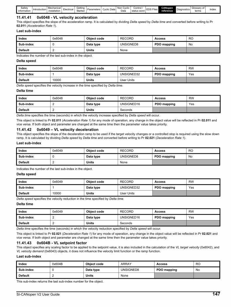
Safety information Introduction Mechanical
installation Electrical Getting Started Parameters Cyclic Data Non Cyclic
DataControl /
status word EDS Files CANopen reference Diagnostics Glossary of
terms Index
11.41.41 0x6048 - VL velocity accelerationThis object specifies the slope of the acceleration ramp. It is calculated by dividing Delta speed by Delta time and converted before writing to Pr 02.011 (Acceleration Rate 1).
Last sub-index
Indicates the number of the last sub-index in the object.
Delta speed
Delta speed specifies the velocity increase in the time specified by Delta time.
Delta time
Delta time specifies the time (seconds) in which the velocity increase specified by Delta speed will occur.This object is linked to Pr 02.011 (Acceleration Rate 1) for any mode of operation, any change in the object value will be reflected in Pr 02.011 and vice versa. If both object and parameter are changed at the same time then the parameter value takes priority.
11.41.42 0x6049 – VL velocity decelerationThis object specifies the slope of the deceleration ramp to be used if the target velocity changes or a controlled stop is required using the slow down ramp. It is calculated by dividing Delta speed by Delta time and converted before writing to Pr 02.021 (Deceleration Rate 1).
Last sub-index
Indicates the number of the last sub-index in the object.
Delta speed
Delta speed specifies the velocity reduction in the time specified by Delta time.
Delta time
Delta time specifies the time (seconds) in which the velocity reduction specified by Delta speed will occur.This object is linked to Pr 02.021 (Deceleration Rate 1) for any mode of operation, any change in the object value will be reflected in Pr 02.021 and vice versa. If both object and parameter are changed at the same time then the parameter value takes priority.
11.41.43 0x604B - VL setpoint factorThis object specifies any scaling factor to be applied to the setpoint value, it is also included in the calculation of the VL target velocity (0x6042), and VL velocity demand (0x6043) objects, it does not influence the velocity limit function or the ramp function.
Last sub-index
This sub-index returns the last sub-index number for the object.
Index 0x6048 Object code RECORD Access RO
Sub-index 0 Data type UNSIGNED8 PDO mapping No
Default 2 Units None
Index 0x6048 Object code RECORD Access RW
Sub-index 1 Data type UNSIGNED32 PDO mapping Yes
Default 10000 Units User Units
Index 0x6048 Object code RECORD Access RW
Sub-index 2 Data type UNSIGNED16 PDO mapping Yes
Default 2 Units Seconds
Index 0x6049 Object code RECORD Access RO
Sub-index 0 Data type UNSIGNED8 PDO mapping No
Default 2 Units None
Index 0x6049 Object code RECORD Access RW
Sub-index 1 Data type UNSIGNED32 PDO mapping Yes
Default 10000 Units User Units
Index 0x6049 Object code RECORD Access RW
Sub-index 2 Data type UNSIGNED16 PDO mapping Yes
Default 2 Units Seconds
Index 0x604B Object code ARRAY Access RO
Sub-index 0 Data type UNSIGNED8 PDO mapping No
Default 2 Units None
SI-CANopen V2 User Guide 147
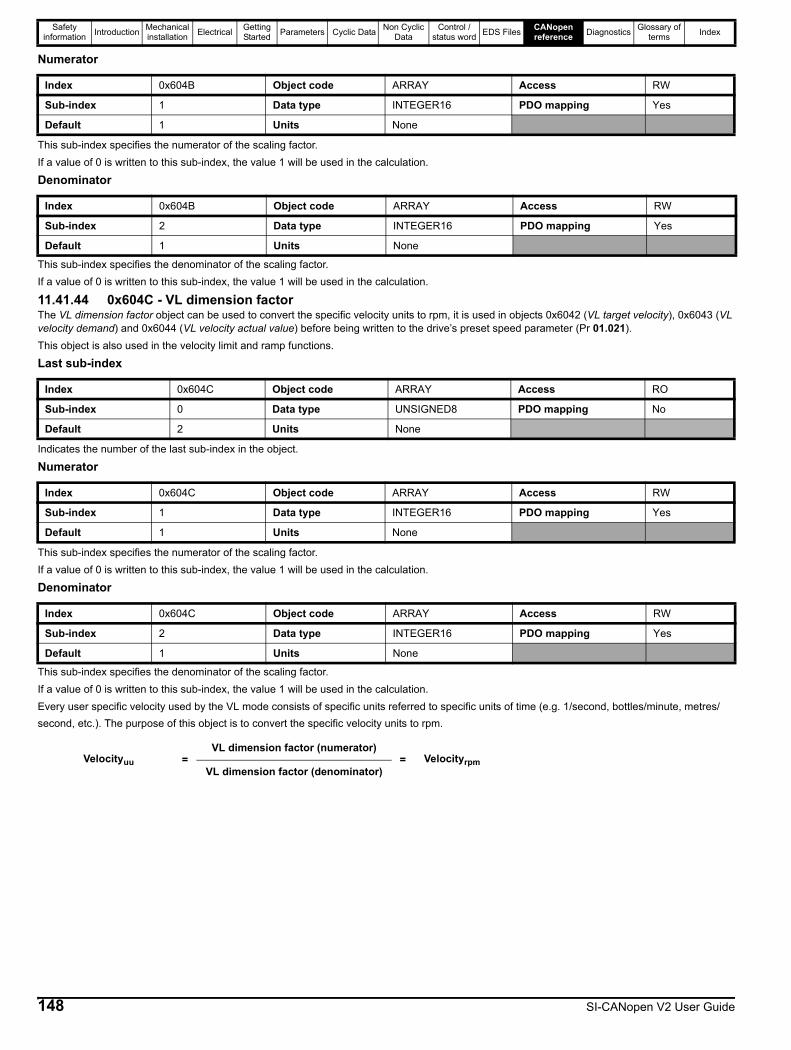
Safety information Introduction Mechanical
installation Electrical Getting Started Parameters Cyclic Data Non Cyclic
DataControl /
status word EDS Files CANopen reference Diagnostics Glossary of
terms Index
Numerator
This sub-index specifies the numerator of the scaling factor.If a value of 0 is written to this sub-index, the value 1 will be used in the calculation.
Denominator
This sub-index specifies the denominator of the scaling factor.If a value of 0 is written to this sub-index, the value 1 will be used in the calculation.
11.41.44 0x604C - VL dimension factorThe VL dimension factor object can be used to convert the specific velocity units to rpm, it is used in objects 0x6042 (VL target velocity), 0x6043 (VL velocity demand) and 0x6044 (VL velocity actual value) before being written to the drive’s preset speed parameter (Pr 01.021).This object is also used in the velocity limit and ramp functions.
Last sub-index
Indicates the number of the last sub-index in the object.
Numerator
This sub-index specifies the numerator of the scaling factor.If a value of 0 is written to this sub-index, the value 1 will be used in the calculation.
Denominator
This sub-index specifies the denominator of the scaling factor.If a value of 0 is written to this sub-index, the value 1 will be used in the calculation.Every user specific velocity used by the VL mode consists of specific units referred to specific units of time (e.g. 1/second, bottles/minute, metres/second, etc.). The purpose of this object is to convert the specific velocity units to rpm.
Index 0x604B Object code ARRAY Access RW
Sub-index 1 Data type INTEGER16 PDO mapping Yes
Default 1 Units None
Index 0x604B Object code ARRAY Access RW
Sub-index 2 Data type INTEGER16 PDO mapping Yes
Default 1 Units None
Index 0x604C Object code ARRAY Access RO
Sub-index 0 Data type UNSIGNED8 PDO mapping No
Default 2 Units None
Index 0x604C Object code ARRAY Access RW
Sub-index 1 Data type INTEGER16 PDO mapping Yes
Default 1 Units None
Index 0x604C Object code ARRAY Access RW
Sub-index 2 Data type INTEGER16 PDO mapping Yes
Default 1 Units None
Velocityuu =VL dimension factor (numerator)
= VelocityrpmVL dimension factor (denominator)
148 SI-CANopen V2 User Guide
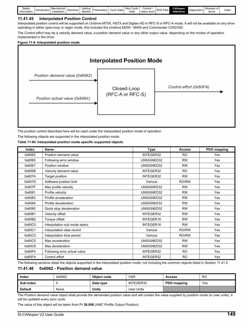
Safety information Introduction Mechanical
installation Electrical Getting Started Parameters Cyclic Data Non Cyclic
DataControl /
status word EDS Files CANopen reference Diagnostics Glossary of
terms Index
11.41.45 Interpolated Position ControlInterpolated position control will be supported on Unidrive M70X, HS7X and Digitax HD in RFC-S or RFC-A mode. It will not be available on any drive operating in either open-loop or regen mode, this includes the Unidrive M200 - M400 and Commander C200/300.The Control effort may be a velocity demand value, a position demand value or any other output value, depending on the modes of operation implemented in the drive.Figure 11-8 Interpolated position mode
The position control described here will be used under the interpolated position mode of operation.The following objects are supported in the interpolated position mode:Table 11-84 Interpolated position mode specific supported objects
The following sections detail the objects supported in the interpolated position mode, not including the common objects listed in Section 11.41.5.
11.41.46 0x6062 - Position demand value
The Position demand value object shall provide the demanded position value and will contain the value supplied by position mode (in user units). It will be updated every sync cycle.The value of this object will be taken from Pr 38.008 (AMC Profile Output Position).
Index Name Type Access PDO mapping0x6062 Position demand value INTEGER32 RO Yes0x6065 Following error window UNSIGNED32 RW Yes0x6067 Position window UNSIGNED32 RW Yes0x606B Velocity demand value INTEGER32 RO Yes0x607A Target position INTEGER32 RW Yes0x607D Software position limit Various RO/RW Yes0x607F Max profile velocity UNSIGNED32 RW Yes0x6081 Profile velocity UNSIGNED32 RW Yes0x6083 Profile acceleration UNSIGNED32 RW Yes0x6084 Profile deceleration UNSIGNED32 RW Yes0x6085 Quick stop deceleration UNSIGNED32 RW Yes0x60B1 Velocity offset INTEGER32 RW Yes0x60B2 Torque offset INTEGER16 RW Yes0x60C0 Interpolation sub mode select INTEGER16 RW Yes0x60C1 Interpolation data record Various RO/RW Yes0x60C2 Interpolation time period Various RO/RW Yes0x60C5 Max acceleration UNSIGNED32 RW Yes0x60C6 Max deceleration UNSIGNED32 RW Yes0x60F4 Following error actual value INTEGER32 RO Yes0x60FA Control effort INTEGER32 RO Yes
Index 0x6062 Object code VAR Access RO
Sub-index 0 Data type INTEGER32 PDO mapping Yes
Default None Units User Units
SI-CANopen V2 User Guide 149
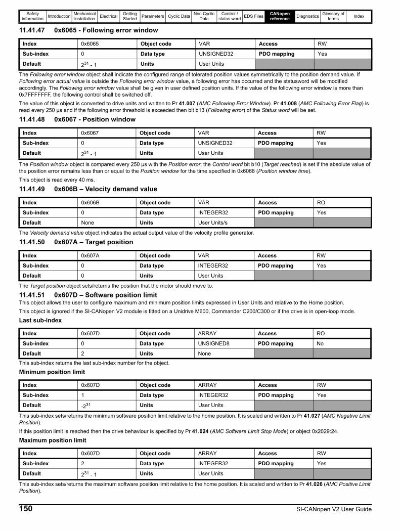
Safety information Introduction Mechanical
installation Electrical Getting Started Parameters Cyclic Data Non Cyclic
DataControl /
status word EDS Files CANopen reference Diagnostics Glossary of
terms Index
11.41.47 0x6065 - Following error window
The Following error window object shall indicate the configured range of tolerated position values symmetrically to the position demand value. If Following error actual value is outside the Following error window value, a following error has occurred and the statusword will be modified accordingly. The Following error window value shall be given in user defined position units. If the value of the following error window is more than 0x7FFFFFFF, the following control shall be switched off.The value of this object is converted to drive units and written to Pr 41.007 (AMC Following Error Window). Pr 41.008 (AMC Following Error Flag) is read every 250 µs and if the following error threshold is exceeded then bit b13 (Following error) of the Status word will be set.
11.41.48 0x6067 - Position window
The Position window object is compared every 250 µs with the Position error; the Control word bit b10 (Target reached) is set if the absolute value of the position error remains less than or equal to the Position window for the time specified in 0x6068 (Position window time).This object is read every 40 ms.
11.41.49 0x606B – Velocity demand value
The Velocity demand value object indicates the actual output value of the velocity profile generator.
11.41.50 0x607A – Target position
The Target position object sets/returns the position that the motor should move to.
11.41.51 0x607D – Software position limitThis object allows the user to configure maximum and minimum position limits expressed in User Units and relative to the Home position.This object is ignored if the SI-CANopen V2 module is fitted on a Unidrive M600, Commander C200/C300 or if the drive is in open-loop mode.
Last sub-index
This sub-index returns the last sub-index number for the object.
Minimum position limit
This sub-index sets/returns the minimum software position limit relative to the home position. It is scaled and written to Pr 41.027 (AMC Negative Limit Position).If this position limit is reached then the drive behaviour is specified by Pr 41.024 (AMC Software Limit Stop Mode) or object 0x2029:24.
Maximum position limit
This sub-index sets/returns the maximum software position limit relative to the home position. It is scaled and written to Pr 41.026 (AMC Positive Limit Position).
Index 0x6065 Object code VAR Access RW
Sub-index 0 Data type UNSIGNED32 PDO mapping Yes
Default 231 - 1 Units User Units
Index 0x6067 Object code VAR Access RW
Sub-index 0 Data type UNSIGNED32 PDO mapping Yes
Default 231 - 1 Units User Units
Index 0x606B Object code VAR Access RO
Sub-index 0 Data type INTEGER32 PDO mapping Yes
Default None Units User Units/s
Index 0x607A Object code VAR Access RW
Sub-index 0 Data type INTEGER32 PDO mapping Yes
Default 0 Units User Units
Index 0x607D Object code ARRAY Access RO
Sub-index 0 Data type UNSIGNED8 PDO mapping No
Default 2 Units None
Index 0x607D Object code ARRAY Access RW
Sub-index 1 Data type INTEGER32 PDO mapping Yes
Default -231 Units User Units
Index 0x607D Object code ARRAY Access RW
Sub-index 2 Data type INTEGER32 PDO mapping Yes
Default 231 - 1 Units User Units
150 SI-CANopen V2 User Guide

Safety information Introduction Mechanical
installation Electrical Getting Started Parameters Cyclic Data Non Cyclic
DataControl /
status word EDS Files CANopen reference Diagnostics Glossary of
terms Index
If this position limit is reached then the drive behaviour is specified by Pr 41.024 (AMC Software Limit Stop Mode) or object 0x2029:24.
11.41.52 0x607F – Max profile velocity
This object specifies and limits the maximum velocity allowed for the given profile.
11.41.53 0x6081 – Profile velocity
This object is used to configure the velocity normally attained at the end of the acceleration ramp, the value is used to configure Pr 38.003 (AMC Profile Maximum Speed) when a new setpoint is commanded.The absolute value of the effective velocity applied is limited by the object 0x6080 (Max motor speed), if they differ then the lower value is used.
11.41.54 0x6083 – Profile acceleration
This object is used to configure the acceleration ramp, it is written to Pr 38.001 (AMC Profile Acceleration) when a new setpoint is commanded.
11.41.55 0x6084 – Profile deceleration
This object is used to configure the deceleration ramp, it is written to Pr 38.002 (AMC Profile Deceleration) in the following circumstances:• The profile position mode is active and a new setpoint position is commanded• The profile position mode is active and the Control word bit b8 (HALT) is set• A state change from OPERATION ENABLED to READY TO SWITCH ON and object 0x605B is set to 1• A state change from OPERATION ENABLED to SWITCHED ON and object 0x605C is set to 1
11.41.56 0x6085 – Quick stop deceleration
This object is used to configure the deceleration ramp rate when the Quick stop function is active and object 0x605A (Quick stop option code) is set to 2 or 6. This object is also used in the following circumstances when the Quick stop is activated:• The fault reaction is activated and the Fault reaction option code (0x605E) is set to 2• The halt function is activated and the Halt option code (0x605D) is set to 2• The SI-CANopen V2 module triggers a network link loss and the Abort connection option code (0x6007) is set to 3
11.41.57 0x60B1 – Velocity offset
This object is summed with the Target velocity (0x60FF), before it is forwarded to the linear interpolator.
Index 0x607F Object code VAR Access RW
Sub-index 0 Data type UNSIGNED32 PDO mapping Yes
Default 231 - 1 Units User Units/s
Index 0x6081 Object code VAR Access RW
Sub-index 0 Data type UNSIGNED32 PDO mapping Yes
Default 0 Units User Units/s
Index 0x6083 Object code VAR Access RW
Sub-index 0 Data type UNSIGNED32 PDO mapping Yes
Default 65536 Units User Units/s2
Index 0x6084 Object code VAR Access RW
Sub-index 0 Data type UNSIGNED32 PDO mapping Yes
Default 65536 Units User Units/s2
Index 0x6085 Object code VAR Access RW
Sub-index 0 Data type UNSIGNED32 PDO mapping Yes
Default 65536 Units User Units/s2
Index 0x60B1 Object code VAR Access RW
Sub-index 0 Data type INTEGER32 PDO mapping Yes
Default 0 Units User Units/s
SI-CANopen V2 User Guide 151
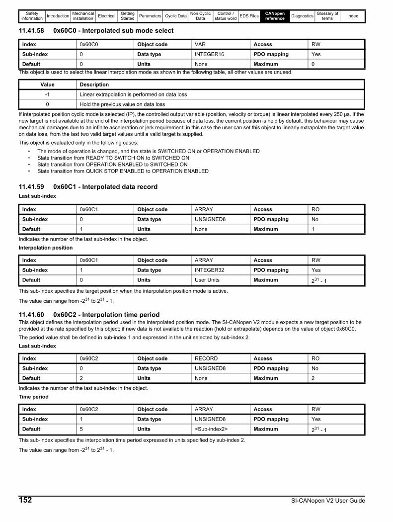
Safety information Introduction Mechanical
installation Electrical Getting Started Parameters Cyclic Data Non Cyclic
DataControl /
status word EDS Files CANopen reference Diagnostics Glossary of
terms Index
11.41.58 0x60C0 - Interpolated sub mode select
This object is used to select the linear interpolation mode as shown in the following table, all other values are unused.
If interpolated position cyclic mode is selected (IP), the controlled output variable (position, velocity or torque) is linear interpolated every 250 µs. If the new target is not available at the end of the interpolation period because of data loss, the current position is held by default. this behaviour may cause mechanical damages due to an infinite acceleration or jerk requirement: in this case the user can set this object to linearly extrapolate the target value on data loss, from the last two valid target values until a valid target is supplied.This object is evaluated only in the following cases:
• The mode of operation is changed, and the state is SWITCHED ON or OPERATION ENABLED• State transition from READY TO SWITCH ON to SWITCHED ON• State transition from OPERATION ENABLED to SWITCHED ON• State transition from QUICK STOP ENABLED to OPERATION ENABLED
11.41.59 0x60C1 - Interpolated data recordLast sub-index
Indicates the number of the last sub-index in the object.Interpolation position
This sub-index specifies the target position when the interpolation position mode is active.
The value can range from -231 to 231 - 1.
11.41.60 0x60C2 - Interpolation time periodThis object defines the interpolation period used in the interpolated position mode. The SI-CANopen V2 module expects a new target position to be provided at the rate specified by this object; if new data is not available the reaction (hold or extrapolate) depends on the value of object 0x60C0.The period value shall be defined in sub-index 1 and expressed in the unit selected by sub-index 2.Last sub-index
Indicates the number of the last sub-index in the object.Time period
This sub-index specifies the interpolation time period expressed in units specified by sub-index 2.
The value can range from -231 to 231 - 1.
Index 0x60C0 Object code VAR Access RW
Sub-index 0 Data type INTEGER16 PDO mapping Yes
Default 0 Units None Maximum 0
Value Description
-1 Linear extrapolation is performed on data loss
0 Hold the previous value on data loss
Index 0x60C1 Object code ARRAY Access RO
Sub-index 0 Data type UNSIGNED8 PDO mapping No
Default 1 Units None Maximum 1
Index 0x60C1 Object code ARRAY Access RW
Sub-index 1 Data type INTEGER32 PDO mapping Yes
Default 0 Units User Units Maximum 231 - 1
Index 0x60C2 Object code RECORD Access RO
Sub-index 0 Data type UNSIGNED8 PDO mapping No
Default 2 Units None Maximum 2
Index 0x60C2 Object code ARRAY Access RW
Sub-index 1 Data type UNSIGNED8 PDO mapping Yes
Default 5 Units <Sub-index2> Maximum 231 - 1
152 SI-CANopen V2 User Guide
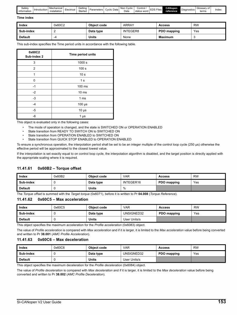
Safety information Introduction Mechanical
installation Electrical Getting Started Parameters Cyclic Data Non Cyclic
DataControl /
status word EDS Files CANopen reference Diagnostics Glossary of
terms Index
Time index
This sub-index specifies the Time period units in accordance with the following table.
This object is evaluated only in the following cases:• The mode of operation is changed, and the state is SWITCHED ON or OPERATION ENABLED• State transition from READY TO SWITCH ON to SWITCHED ON• State transition from OPERATION ENABLED to SWITCHED ON• State transition from QUICK STOP ENABLED to OPERATION ENABLED
To ensure a synchronous operation, the interpolation period shall be set to be an integer multiple of the control loop cycle (250 µs) otherwise the effective period will be approximated to the closest lowest value.If the interpolation is set exactly equal to on control loop cycle, the interpolation algorithm is disabled, and the target position is directly applied with the appropriate scaling where it is required.
11.41.61 0x60B2 – Torque offset
The Torque offset is summed with the Target torque (0x6071), before it is written to Pr 04.008 (Torque Reference).
11.41.62 0x60C5 – Max acceleration
This object specifies the maximum acceleration for the Profile acceleration (0x6083) object.The value of Profile acceleration is compared with Max acceleration and if it is larger, it is limited to the Max acceleration value before being converted and written to Pr 38.001 (AMC Profile Acceleration).
11.41.63 0x60C6 – Max deceleration
This object specifies the maximum deceleration for the Profile deceleration (0x6084) object.The value of Profile deceleration is compared with Max deceleration and if it is larger, it is limited to the Max deceleration value before being converted and written to Pr 38.002 (AMC Profile Deceleration).
Index 0x60C2 Object code ARRAY Access RW
Sub-index 2 Data type INTEGER8 PDO mapping Yes
Default -4 Units None Maximum 3
0x60C2Sub-index 2 Time period units
3 1000 s
2 100 s
1 10 s
0 1 s
-1 100 ms
-2 10 ms
-3 1 ms
-4 100 µs
-5 10 µs
-6 1 µs
Index 0x60B2 Object code VAR Access RW
Sub-index 0 Data type INTEGER16 PDO mapping Yes
Default 0 Units %
Index 0x60C5 Object code VAR Access RW
Sub-index 0 Data type UNSIGNED32 PDO mapping Yes
Default 0 Units User Units/s
Index 0x60C6 Object code VAR Access RW
Sub-index 0 Data type UNSIGNED32 PDO mapping Yes
Default 0 Units User Units/s
SI-CANopen V2 User Guide 153

Safety information Introduction Mechanical
installation Electrical Getting Started Parameters Cyclic Data Non Cyclic
DataControl /
status word EDS Files CANopen reference Diagnostics Glossary of
terms Index
11.41.64 0x60F4 - Following error actual value
The Following error actual value object shall provide the actual value of the following error. The value shall be given in user-defined position units. If Following error actual value is outside the Following error window value, a following error has occurred, and the Status word will be modified accordingly. AMC Position Error (Pr 39.008) gives the difference between the final position reference and the AMC Slave Position (Pr 33.004) in User Units.
11.41.65 0x60FA - Control effort
The Control effort object shall provide the control effort as the output of the position control loop and is derived from the AMC Output Speed (Pr 39.012) and converted to User Units/s.
Index 0x60F4 Object code VAR Access RO
Sub-index 0 Data type INTEGER32 PDO mapping Yes
Default None Units User Units
Index 0x60FA Object code VAR Access RO
Sub-index 0 Data type INTEGER32 PDO mapping Yes
Default None Units User Units/s
154 SI-CANopen V2 User Guide

Safety information Introduction Mechanical
installation Electrical Getting Started Parameters Cyclic Data Non Cyclic
DataControl /
status word EDS Files CANopen reference Diagnostics Glossary of
terms Index
11.41.66 Profile position modeThe profile position mode is only supported on Unidrive M70X and Digitax HD (M75X) drives in RFC-A or RFC-S modes and Pr S.01.021 (Compatibility Mode) set to “CIA 402 Profile”.The profile position mode allows the user to execute point-to-point positioning using the drive position profile generator. The setting of setpoints is controlled by the timing of the Control word bits b4 (NEW SETPOINT) and b5 (CHANGE SETPOINT IMMEDIATELY). It is possible to request an absolute position or position relative to the previous absolute position.The position profile mode allows the handling of a rotary axis setting the axis period in object 0x607B:02 (Position range limits).If either of the sub-index values are zero, this will disable the function, otherwise the object 0x60F2 (Positioning option code) allows the user to configure the rotation direction; relative positioning is not allowed for all option settings. If a relative position is requested but is not allowed due to the setting of object 0x60F2, the setpoint will be discarded on the rising edge of the NEW SETPOINT bit (b4) and the Status word acknowledge bit (b12) will not be set.The data flow between the objects and drive parameters is shown in Figure 11-9.Figure 11-9 Profile position mode
Control word usageThe Control word for the profile position mode differs from the standard configuration as shown below.
Bits b15 – b10 b9 b8 b7 b6 b5 b4 b3 – b0
Name CHANGE ON SETPOINT
HALTABSOLUTE
or RELATIVECHANGE SETPOINT
IMMEDIATELYNEW SET-
POINT
b9 b5 b4 Description
0 0Process a new setpoint value.If the motor shaft is moving, the new position is buffered (unless the buffer is already busy), the buffered move-ment will start after the current movement completes.
X 1Process a new setpoint value.The target position is immediately updated even if an existing movement is in progress.
1 0Not supported.The new setpoint value is ignored.
Bit Value Description
b60 The target position in object 0x607A is absolute1 The target position is relative to the previous setpoint value
b80 The motor shaft can move, the Control word bit b4 is evaluated1 The motor decelerates according to the object 0x605D (Halt option code)
SI-CANopen V2 User Guide 155
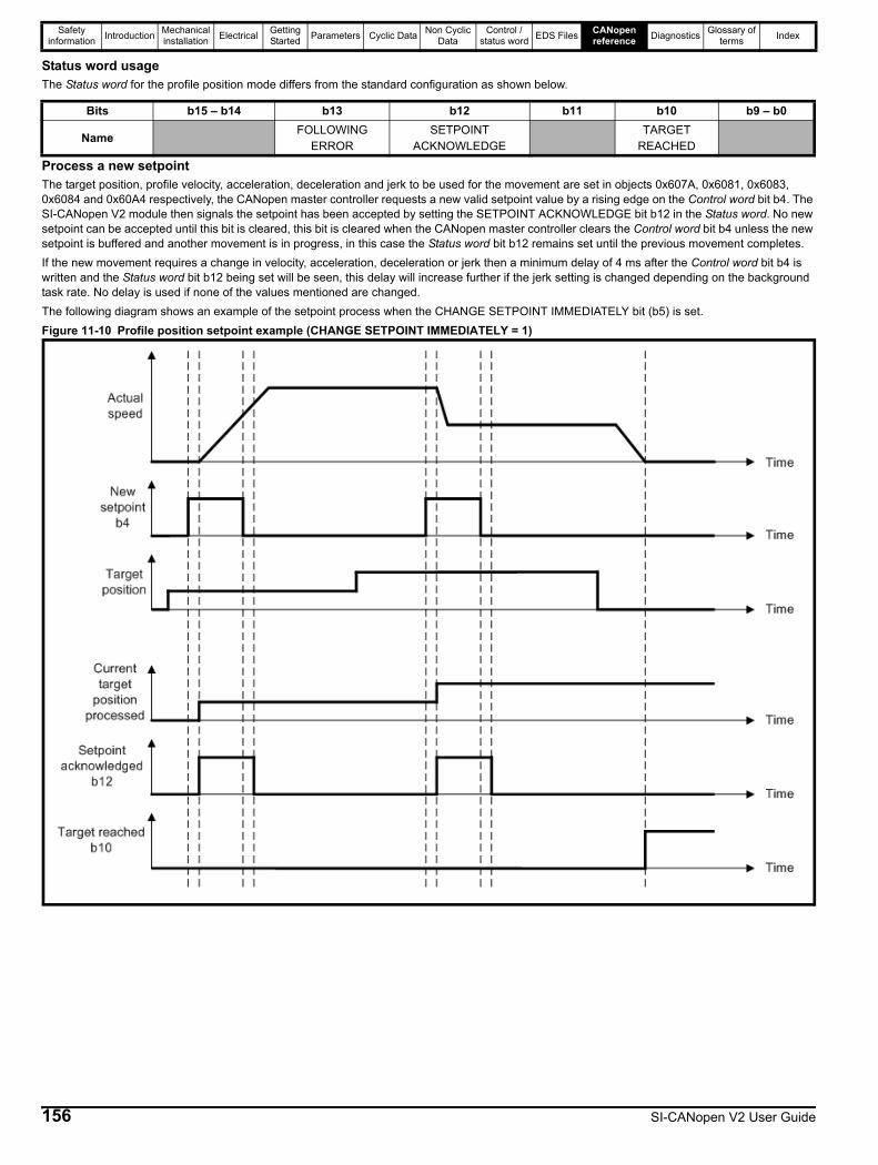
Safety information Introduction Mechanical
installation Electrical Getting Started Parameters Cyclic Data Non Cyclic
DataControl /
status word EDS Files CANopen reference Diagnostics Glossary of
terms Index
Status word usageThe Status word for the profile position mode differs from the standard configuration as shown below.
Process a new setpointThe target position, profile velocity, acceleration, deceleration and jerk to be used for the movement are set in objects 0x607A, 0x6081, 0x6083, 0x6084 and 0x60A4 respectively, the CANopen master controller requests a new valid setpoint value by a rising edge on the Control word bit b4. The SI-CANopen V2 module then signals the setpoint has been accepted by setting the SETPOINT ACKNOWLEDGE bit b12 in the Status word. No new setpoint can be accepted until this bit is cleared, this bit is cleared when the CANopen master controller clears the Control word bit b4 unless the new setpoint is buffered and another movement is in progress, in this case the Status word bit b12 remains set until the previous movement completes.If the new movement requires a change in velocity, acceleration, deceleration or jerk then a minimum delay of 4 ms after the Control word bit b4 is written and the Status word bit b12 being set will be seen, this delay will increase further if the jerk setting is changed depending on the background task rate. No delay is used if none of the values mentioned are changed.The following diagram shows an example of the setpoint process when the CHANGE SETPOINT IMMEDIATELY bit (b5) is set.Figure 11-10 Profile position setpoint example (CHANGE SETPOINT IMMEDIATELY = 1)
Bits b15 – b14 b13 b12 b11 b10 b9 – b0
Name FOLLOWING ERROR
SETPOINT ACKNOWLEDGE
TARGET REACHED
156 SI-CANopen V2 User Guide

Safety information Introduction Mechanical
installation Electrical Getting Started Parameters Cyclic Data Non Cyclic
DataControl /
status word EDS Files CANopen reference Diagnostics Glossary of
terms Index
The following diagram shows an example of the setpoint process when the CHANGE SETPOINT IMMEDIATELY bit (b5) is cleared.Figure 11-11 Profile position setpoint example (CHANGE SETPOINT IMMEDIATELY = 0)
In addition to the common objects listed in section 11.41.5 and the basic position objects listed in section 11.41.44, the following objects are specific to the profile position mode:Table 11-85 Profile position mode specific supported objects
The following objects are unique to this profile, all other objects are detailed elsewhere in this document.
11.41.67 0x6068 – Position window time
The Position window time object specifies the duration of time (milliseconds) in which the actual motor shaft position must remain within the Position window (0x6067) threshold to consider the target position reached.
Index Name Type Access PDO mapping
0x6067 Position window UNSIGNED32 RW Yes
0x6068 Position window time UNSIGNED16 RW Yes
0x606C Velocity actual value INTEGER32 RO Yes
0x607B Position range limit Various RO/RW Yes
0x60A4 Profile jerk Various RO/RW Yes
0x60F2 Positioning option code UNSIGNED16 RW Yes
Index 0x6068 Object code VAR Access RW
Sub-index 0 Data type UNSIGNED16 PDO mapping Yes
Default 0 Units ms
SI-CANopen V2 User Guide 157
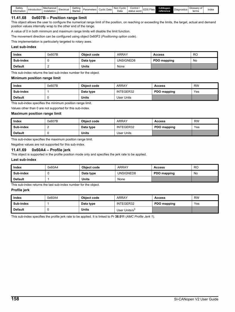
Safety information Introduction Mechanical
installation Electrical Getting Started Parameters Cyclic Data Non Cyclic
DataControl /
status word EDS Files CANopen reference Diagnostics Glossary of
terms Index
11.41.68 0x607B – Position range limitThis object allows the user to configure the numerical range limit of the position, on reaching or exceeding the limits, the target, actual and demand position values internally wrap to the other end of the range.A value of 0 in both minimum and maximum range limits will disable the limit function.The movement direction can be configured using object 0x60F2 (Positioning option code).This implementation is particularly targeted to rotary axes.
Last sub-index
This sub-index returns the last sub-index number for the object.
Minimum position range limit
This sub-index specifies the minimum position range limit.Values other than 0 are not supported for this sub-index.
Maximum position range limit
This sub-index specifies the maximum position range limit.Negative values are not supported for this sub-index.
11.41.69 0x60A4 – Profile jerkThis object is supported in the profile position mode only and specifies the jerk rate to be applied.
Last sub-index
This sub-index returns the last sub-index number for the object.
Profile jerk
This sub-index specifies the profile jerk rate to be applied. It is linked to Pr 38.011 (AMC Profile Jerk 1).
Index 0x607B Object code ARRAY Access RO
Sub-index 0 Data type UNSIGNED8 PDO mapping No
Default 2 Units None
Index 0x607B Object code ARRAY Access RW
Sub-index 1 Data type INTEGER32 PDO mapping Yes
Default 0 Units User Units
Index 0x607B Object code ARRAY Access RW
Sub-index 2 Data type INTEGER32 PDO mapping Yes
Default 0 Units User Units
Index 0x60A4 Object code ARRAY Access RO
Sub-index 0 Data type UNSIGNED8 PDO mapping No
Default 1 Units None
Index 0x60A4 Object code ARRAY Access RW
Sub-index 1 Data type INTEGER32 PDO mapping Yes
Default 0 Units User Units/s3
158 SI-CANopen V2 User Guide
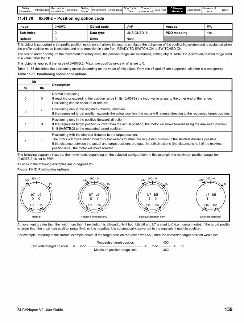
Safety information Introduction Mechanical
installation Electrical Getting Started Parameters Cyclic Data Non Cyclic
DataControl /
status word EDS Files CANopen reference Diagnostics Glossary of
terms Index
11.41.70 0x60F2 – Positioning option code
This object is supported in the profile position mode only, it allows the user to configure the behaviour of the positioning system and is evaluated when the profile position mode is selected and on a transition in state from READY TO SWITCH ON to SWITCHED ON.The bits b6 and b7 configure the movement for rotary axes, the position range limit is enabled, setting object 0x607B:2 (Maximum position range limit) to a value other than 0.This object is ignored if the value of 0x607B:2 (Maximum position range limit) is set to 0.Table 11-86 describes the positioning action depending on the value of this object. Only bits b6 and b7 are supported, all other bits are ignored.Table 11-86 Positioning option code actions
The following diagrams illustrate the movements depending on the selected configuration. In this example the maximum position range limit (0x607B:2) is set to 360º.All units in the following examples are in degrees (º).Figure 11-12 Positioning options
A movement greater than the limit (more than 1 revolution) is allowed only if both bits b6 and b7 are set to 0 (i.e. normal mode). If the target position is larger than the maximum position range limit, or it is negative, it is automatically converted to the equivalent modulo position.
For example, referring to the Normal example above, if the target position requested was 450, then the converted target position would be:
Index 0x60F2 Object code VAR Access RW
Sub-index 0 Data type UNSIGNED16 PDO mapping Yes
Default 0 Units None
BitDescription
b7 b6
0 0Normal positioning.If reaching or exceeding the position range limits (0x607B) the input value wraps to the other end of the range.Positioning can be absolute or relative.
0 1Positioning only in the negative (reverse) direction.If the requested target position exceeds the actual position, the motor will reverse direction to the requested target position.
1 0Positioning only in the positive (forward) direction.If the requested target position is lower than the actual position, the motor will move forward using the maximum position limit (0x607B:2) to the requested target position.
1 1
Positioning with the shortest distance to the target position.The motor will move either forward or backwards to attain the requested position in the shortest distance possible.If the distance between the actual and target positions are equal in both directions (the distance is half of the maximum position limit), the motor will move forward.
Converted target position = modRequested target position
= mod450
= 90Maximum position range limit 360
b7 b60 0
50330 360 = 0
150210
Normal
b7 b60 1
50330 360 = 0
150210
Negative direction only
b7 b61 0
50330 360 = 0
150210
Positive direction only
b7 b61 1
50330 360 = 0
150210
Shortest distance
SI-CANopen V2 User Guide 159

Safety information Introduction Mechanical
installation Electrical Getting Started Parameters Cyclic Data Non Cyclic
DataControl /
status word EDS Files CANopen reference Diagnostics Glossary of
terms Index
Figure 11-13 shows an example for an absolute positioning system using the Normal mode and a target position larger than the limit (360 in this example). The actual position is 90 and absolute target position is 630.The axis will move in the positive (forward) direction from 90, once through the maximum position range limit of 360 to finish at the converted target position of 270 (absolute 630).Figure 11-13 Absolute position example
The relative positioning is allowed only if the Normal mode is selected (bits b6 and b7 are both 0).If bits b6 and b7 are not 0 and Control word bit b6 (Abs/Rel) is set when a new setpoint is applied by Control word bit b4 (NEW SETPOINT), the new setpoint will not be processed.
11.41.71 Homing modeHoming mode will operate on Unidrive M70X/M88X and Digitax HD drives in either RFC-S mode or RFC-A mode. It will not be available on any drive in open-loop or regen mode, this includes Unidrive M200 - M400 and Commander C200/C300.Table 11-87 shows the Homing mode specific objects not detailed elsewhere in this User Guide. Homing mode is enabled by setting the Modes of operation object to 6 (see Table 11-78 Modes of operation codes ).The homing switch source, if required, will be taken from object 0x3003. The limit switch values, if required, will be read from the drive; the limit switches are inputs mapped to Pr 06.035 and Pr 06.036, the user must ensure these parameters are mapped to the proper I/O.If an index pulse is necessary, SI-CANopen V2 will read the marker or freeze from the currently selected feedback source (object 0x3000). If the freeze function is selected, the appropriate drive parameters Pr 03.100 (F1 Freeze Trigger Source), Pr 03.101 (F1 Freeze Mode), Pr 03.102 (F1 Freeze Position Source), Pr 03.105 (F2 Freeze Trigger Source), Pr 03.106 (F2 Freeze Mode), Pr 03.107 (F2 Freeze Position Source), should be set correctly before use.Table 11-87 Homing mode specific objects
Index Name Type Access PDO mapping
0x607C Home offset INTEGER32 RW Yes
0x6098 Homing method INTEGER8 RW Yes
0x6099 Homing speeds Various RO/RW Yes
0x609A Homing acceleration UNSIGNED32 RW Yes
-360 -180 0-90-270 90 180 270 360 45090
540180
630270
720360
Start position Target position
160 SI-CANopen V2 User Guide
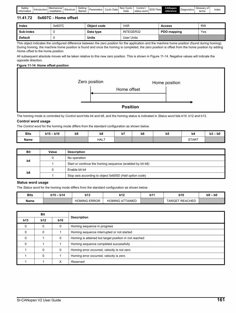
Safety information Introduction Mechanical
installation Electrical Getting Started Parameters Cyclic Data Non Cyclic
DataControl /
status word EDS Files CANopen reference Diagnostics Glossary of
terms Index
11.41.72 0x607C - Home offset
This object indicates the configured difference between the zero position for the application and the machine home position (found during homing). During homing, the machine home position is found and once the homing is completed, the zero position is offset from the home position by adding Home offset to the home position.All subsequent absolute moves will be taken relative to this new zero position. This is shown in Figure 11-14. Negative values will indicate the opposite direction.Figure 11-14 Home offset position
The homing mode is controlled by Control word bits b4 and b8, and the homing status is indicated in Status word bits b10, b12 and b13.
Control word usageThe Control word for the homing mode differs from the standard configuration as shown below.
Status word usageThe Status word for the homing mode differs from the standard configuration as shown below.
Index 0x607C Object code VAR Access RW
Sub-index 0 Data type INTEGER32 PDO mapping Yes
Default 0 Units User Units
Zero position Home position Home offset
Position
Bits b15 – b10 b9 b8 b7 b6 b5 b4 b3 – b0
Name HALT START
Bit Value Description
b40 No operation
1 Start or continue the homing sequence (enabled by bit b8)
b80 Enable bit b4
1 Stop axis according to object 0x605D (Halt option code)
Bits b15 – b14 b13 b12 b11 b10 b9 – b0
Name HOMING ERROR HOMING ATTAINED TARGET REACHED
BitDescription
b13 b12 b10
0 0 0 Homing sequence in progress
0 0 1 Homing sequence interrupted or not started
0 1 0 Homing is attained but target position in not reached
0 1 1 Homing sequence completed successfully
1 0 0 Homing error occurred, velocity is not zero
1 0 1 Homing error occurred, velocity is zero
1 1 X Reserved
SI-CANopen V2 User Guide 161
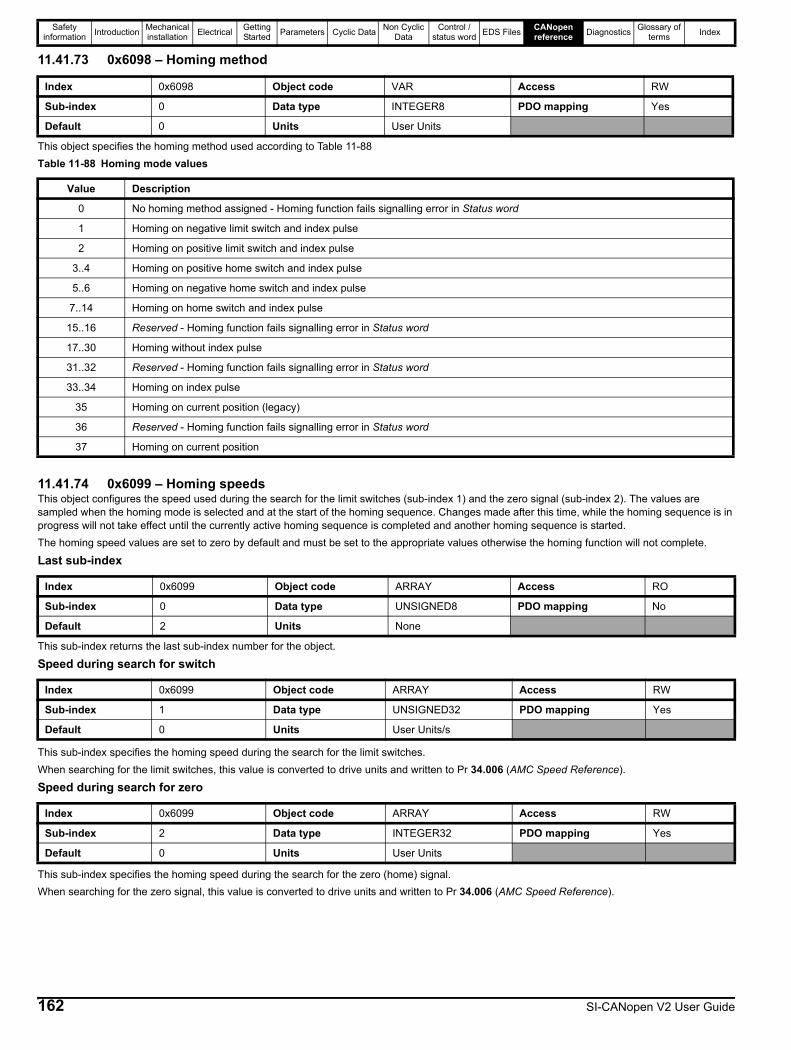
Safety information Introduction Mechanical
installation Electrical Getting Started Parameters Cyclic Data Non Cyclic
DataControl /
status word EDS Files CANopen reference Diagnostics Glossary of
terms Index
11.41.73 0x6098 – Homing method
This object specifies the homing method used according to Table 11-88Table 11-88 Homing mode values
11.41.74 0x6099 – Homing speedsThis object configures the speed used during the search for the limit switches (sub-index 1) and the zero signal (sub-index 2). The values are sampled when the homing mode is selected and at the start of the homing sequence. Changes made after this time, while the homing sequence is in progress will not take effect until the currently active homing sequence is completed and another homing sequence is started.The homing speed values are set to zero by default and must be set to the appropriate values otherwise the homing function will not complete.
Last sub-index
This sub-index returns the last sub-index number for the object.
Speed during search for switch
This sub-index specifies the homing speed during the search for the limit switches.When searching for the limit switches, this value is converted to drive units and written to Pr 34.006 (AMC Speed Reference).
Speed during search for zero
This sub-index specifies the homing speed during the search for the zero (home) signal.When searching for the zero signal, this value is converted to drive units and written to Pr 34.006 (AMC Speed Reference).
Index 0x6098 Object code VAR Access RW
Sub-index 0 Data type INTEGER8 PDO mapping Yes
Default 0 Units User Units
Value Description
0 No homing method assigned - Homing function fails signalling error in Status word
1 Homing on negative limit switch and index pulse
2 Homing on positive limit switch and index pulse
3..4 Homing on positive home switch and index pulse
5..6 Homing on negative home switch and index pulse
7..14 Homing on home switch and index pulse
15..16 Reserved - Homing function fails signalling error in Status word
17..30 Homing without index pulse
31..32 Reserved - Homing function fails signalling error in Status word
33..34 Homing on index pulse
35 Homing on current position (legacy)
36 Reserved - Homing function fails signalling error in Status word
37 Homing on current position
Index 0x6099 Object code ARRAY Access RO
Sub-index 0 Data type UNSIGNED8 PDO mapping No
Default 2 Units None
Index 0x6099 Object code ARRAY Access RW
Sub-index 1 Data type UNSIGNED32 PDO mapping Yes
Default 0 Units User Units/s
Index 0x6099 Object code ARRAY Access RW
Sub-index 2 Data type INTEGER32 PDO mapping Yes
Default 0 Units User Units
162 SI-CANopen V2 User Guide

Safety information Introduction Mechanical
installation Electrical Getting Started Parameters Cyclic Data Non Cyclic
DataControl /
status word EDS Files CANopen reference Diagnostics Glossary of
terms Index
11.41.75 0x609A – Homing acceleration
This object specifies both the acceleration and deceleration ramps used during the homing sequence. It is converted to drive units and written to Pr 38.001 (AMC Profile Acceleration) and Pr 38.002 (AMC Profile Deceleration) when the homing mode is selected or when the homing sequence is started. Changes made to this object during a homing sequence will not take effect until the active homing sequence has completed and another homing sequence is started.
11.41.76 Homing method 1 (Homing on negative limit switch and index pulse)Using this method as shown in Figure 11-15, the direction of movement is leftward if the negative limit switch is inactive. The home position will be at the first index pulse to the right of the position where the negative limit switch becomes inactive.Figure 11-15 Homing method 1 (Homing on negative limit switch and index pulse)
Index 0x609A Object code VAR Access RW
Sub-index 0 Data type UNSIGNED32 PDO mapping Yes
Default 65535 Units User Units/s2
SI-CANopen V2 User Guide 163
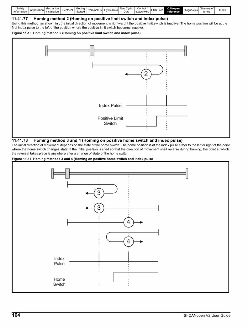
Safety information Introduction Mechanical
installation Electrical Getting Started Parameters Cyclic Data Non Cyclic
DataControl /
status word EDS Files CANopen reference Diagnostics Glossary of
terms Index
11.41.77 Homing method 2 (Homing on positive limit switch and index pulse)Using this method, as shown in , the initial direction of movement is rightward if the positive limit switch is inactive. The home position will be at the first index pulse to the left of the position where the positive limit switch becomes inactive.Figure 11-16 Homing method 2 (Homing on positive limit switch and index pulse)
11.41.78 Homing method 3 and 4 (Homing on positive home switch and index pulse)The initial direction of movement depends on the state of the home switch. The home position is at the index pulse either to the left or right of the point where the home switch changes state. If the initial position is sited so that the direction of movement shall reverse during homing, the point at which the reversal takes place is anywhere after a change of state of the home switch.Figure 11-17 Homing methods 3 and 4 (Homing on positive home switch and index pulse
164 SI-CANopen V2 User Guide
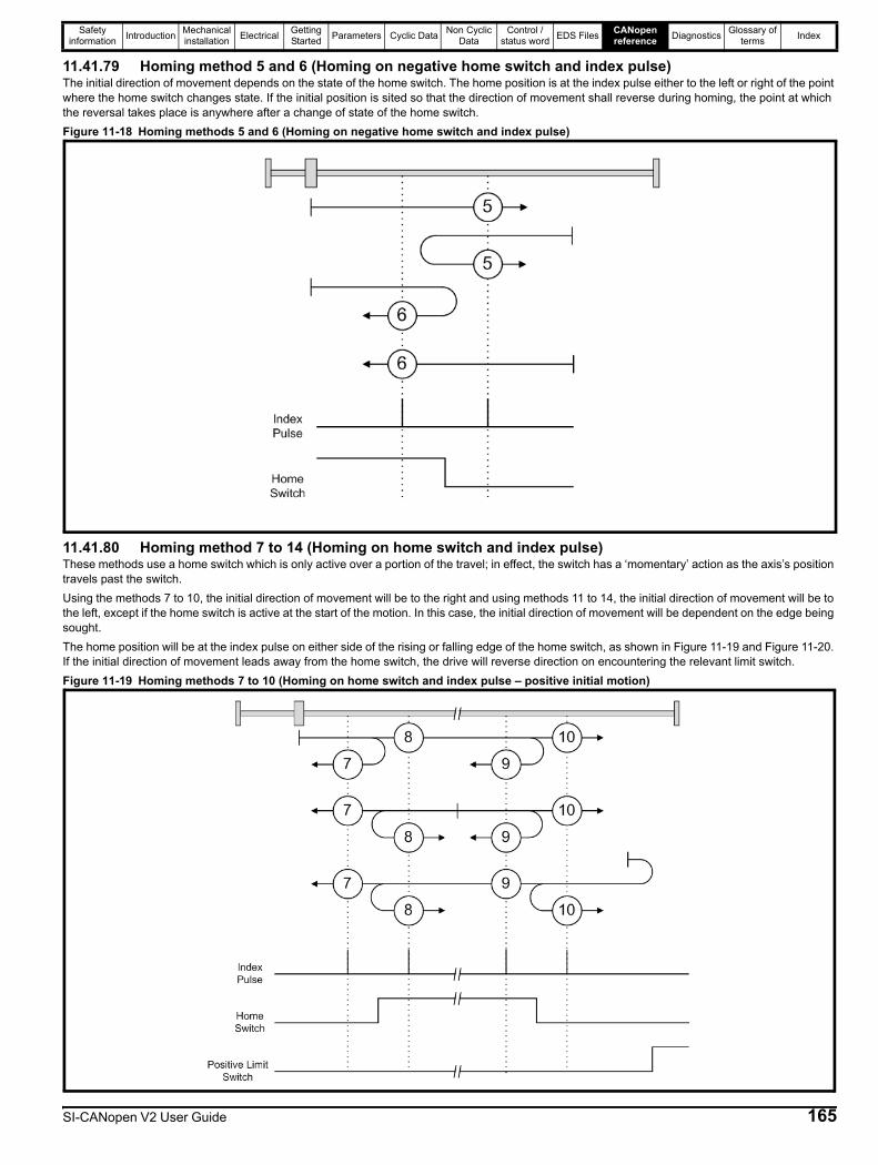
Safety information Introduction Mechanical
installation Electrical Getting Started Parameters Cyclic Data Non Cyclic
DataControl /
status word EDS Files CANopen reference Diagnostics Glossary of
terms Index
11.41.79 Homing method 5 and 6 (Homing on negative home switch and index pulse)The initial direction of movement depends on the state of the home switch. The home position is at the index pulse either to the left or right of the point where the home switch changes state. If the initial position is sited so that the direction of movement shall reverse during homing, the point at which the reversal takes place is anywhere after a change of state of the home switch.Figure 11-18 Homing methods 5 and 6 (Homing on negative home switch and index pulse)
11.41.80 Homing method 7 to 14 (Homing on home switch and index pulse)These methods use a home switch which is only active over a portion of the travel; in effect, the switch has a ‘momentary’ action as the axis’s position travels past the switch.Using the methods 7 to 10, the initial direction of movement will be to the right and using methods 11 to 14, the initial direction of movement will be to the left, except if the home switch is active at the start of the motion. In this case, the initial direction of movement will be dependent on the edge being sought. The home position will be at the index pulse on either side of the rising or falling edge of the home switch, as shown in Figure 11-19 and Figure 11-20. If the initial direction of movement leads away from the home switch, the drive will reverse direction on encountering the relevant limit switch.Figure 11-19 Homing methods 7 to 10 (Homing on home switch and index pulse – positive initial motion)
SI-CANopen V2 User Guide 165

Safety information Introduction Mechanical
installation Electrical Getting Started Parameters Cyclic Data Non Cyclic
DataControl /
status word EDS Files CANopen reference Diagnostics Glossary of
terms Index
Figure 11-20 Homing methods 11 to 14 (Homing on home switch and index pulse – negative initial motion)
11.41.81 Homing method 17 to 30 (Homing without index pulse)These methods are similar to methods 3 to 14 except that the home position is not dependent on the index pulse, but only on the relevant home transitions.For example, methods 19 and 20 are similar to methods 3 and 4 as shown in Figure 11-21.Figure 11-21 Homing methods 19 and 20 (Homing on positive home switch)
166 SI-CANopen V2 User Guide
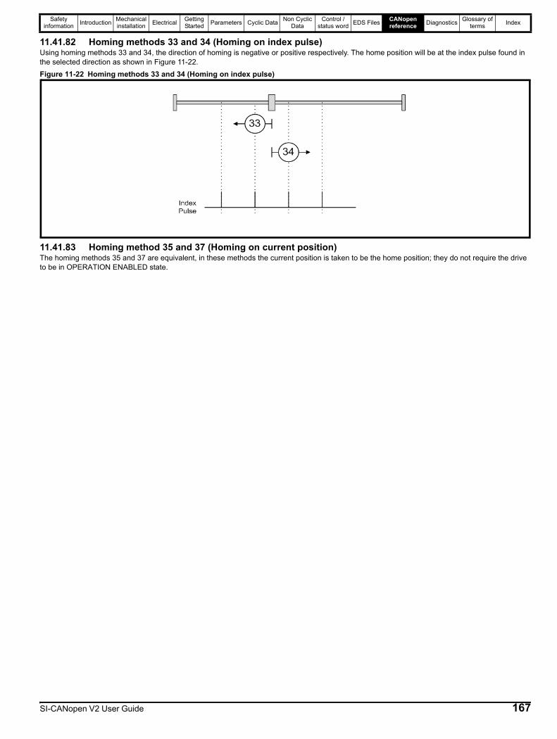
Safety information Introduction Mechanical
installation Electrical Getting Started Parameters Cyclic Data Non Cyclic
DataControl /
status word EDS Files CANopen reference Diagnostics Glossary of
terms Index
11.41.82 Homing methods 33 and 34 (Homing on index pulse)Using homing methods 33 and 34, the direction of homing is negative or positive respectively. The home position will be at the index pulse found in the selected direction as shown in Figure 11-22.Figure 11-22 Homing methods 33 and 34 (Homing on index pulse)
11.41.83 Homing method 35 and 37 (Homing on current position)The homing methods 35 and 37 are equivalent, in these methods the current position is taken to be the home position; they do not require the drive to be in OPERATION ENABLED state.
SI-CANopen V2 User Guide 167
Safety information Introduction Mechanical
installation Electrical Getting Started Parameters Cyclic Data Non Cyclic
DataControl /
status word EDS Files CANopen reference Diagnostics Glossary of
terms Index
12 Diagnostics12.1 OverviewThis section provides basic diagnostic information intended to resolve the most common problems encountered when setting up an SI-CANopen V2 module on a CANopen network.A high percentage of problems reported are basic set-up problems which can usually be solved by reading the information in this chapter. If after reading this chapter you are still experiencing problems, please contact your supplier for support.
12.1.1 Drive trip display codesIf the option module detects an error during operation, it will force a trip on the drive. However, the trip string displayed on the drive will only indicate which slot initiated the trip. The exact reason for the trip will be indicated in the drive trip code parameters (Pr 10.020 and Pr 10.070).Table 12-1 shows the possible trips that will be displayed on the drive when a problem is detected with the option module or when the option module initiates a trip.Table 12-1 Drive trip display codes
Emergency error code 0x8210 is a predefined CANopen error code as defined in the CANopen protocol specification, it is not an error code generated by the SI-CANopen V2 option module.The CANopen protocol gives the definition of 0x8210 as that of the PDO producer (Master) that is writing a PDO which is shorter than that which is defined in the module (consumer).So the consumer will not handle the PDO if it is shorter than the configured length, and will then inform the producer with the error code 0x8210 that a PDO is shorter than expected and has then been received and discarded.
Trip DescriptionSlotX HF The drive has detected that an option module is present but is unable to communicate with it due to a hardware fault.SlotX Error User trip generated by the option moduleSlotX Not Fitted This trip will occur if a drive slot was previously configured with an option module but on power up, no option module was detected.
SlotX DifferentThis trip will occur if a drive slot was previously configured with an option module but on power up, a different option module was detected. Replacing the option module with another one of the same ID number will not initiate this trip.The trip will also occur if an option module is installed to a previously unused slot.
168 SI-CANopen V2 User Guide
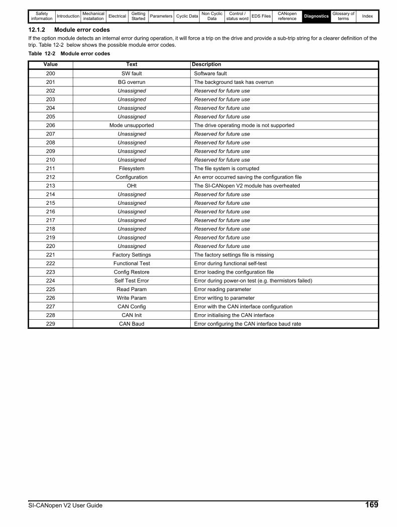
Safety information Introduction Mechanical
installation Electrical Getting Started Parameters Cyclic Data Non Cyclic
DataControl /
status word EDS Files CANopen reference Diagnostics Glossary of
terms Index
12.1.2 Module error codesIf the option module detects an internal error during operation, it will force a trip on the drive and provide a sub-trip string for a clearer definition of the trip. Table 12-2 below shows the possible module error codes.Table 12-2 Module error codes
Value Text Description200 SW fault Software fault201 BG overrun The background task has overrun202 Unassigned Reserved for future use203 Unassigned Reserved for future use204 Unassigned Reserved for future use205 Unassigned Reserved for future use206 Mode unsupported The drive operating mode is not supported207 Unassigned Reserved for future use208 Unassigned Reserved for future use209 Unassigned Reserved for future use210 Unassigned Reserved for future use211 Filesystem The file system is corrupted212 Configuration An error occurred saving the configuration file213 OHt The SI-CANopen V2 module has overheated214 Unassigned Reserved for future use215 Unassigned Reserved for future use216 Unassigned Reserved for future use217 Unassigned Reserved for future use218 Unassigned Reserved for future use219 Unassigned Reserved for future use220 Unassigned Reserved for future use221 Factory Settings The factory settings file is missing222 Functional Test Error during functional self-test223 Config Restore Error loading the configuration file224 Self Test Error Error during power-on test (e.g. thermistors failed)225 Read Param Error reading parameter226 Write Param Error writing to parameter227 CAN Config Error with the CAN interface configuration228 CAN Init Error initialising the CAN interface229 CAN Baud Error configuring the CAN interface baud rate
SI-CANopen V2 User Guide 169
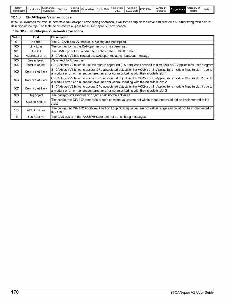
Safety information Introduction Mechanical
installation Electrical Getting Started Parameters Cyclic Data Non Cyclic
DataControl /
status word EDS Files CANopen reference Diagnostics Glossary of
terms Index
12.1.3 SI-CANopen V2 error codesIf the SI-CANopen V2 module detects a SI-CANopen error during operation, it will force a trip on the drive and provide a sub-trip string for a clearer definition of the trip. The table below shows all possible SI-CANopen V2 error codes.Table 12-3 SI-CANopen V2 network error codes
Value Text Description0 No trip The SI-CANopen V2 module is healthy and not tripped.
100 Link Loss The connection to the CANopen network has been lost.101 Bus Off The CAN layer of the module has entered the BUS OFF state.102 Heartbeat error SI-CANopen V2 has missed the CANopen master’s heartbeat message103 Unassigned Reserved for future use104 Startup object SI-CANopen V2 failed to use the startup object list (0x2860) when defined in a MCi2xx or SI-Applications user program
105 Comm slot 1 err SI-CANopen V2 failed to access DPL associated objects in the MCi2xx or SI-Applications module fitted in slot 1 due to a module error, or has encountered an error communicating with the module is slot 1
106 Comm slot 2 err SI-CANopen V2 failed to access DPL associated objects in the MCi2xx or SI-Applications module fitted in slot 2 due to a module error, or has encountered an error communicating with the module is slot 2
107 Comm slot 3 err SI-CANopen V2 failed to access DPL associated objects in the MCi2xx or SI-Applications module fitted in slot 3 due to a module error, or has encountered an error communicating with the module is slot 3
108 Bkg object The background association object could not be activated
109 Scaling Failure The configured CiA 402 gear ratio or feed constant values are not within range and could not be implemented in the AMC
110 APLS Failure The configured CiA 402 Additional Position Loop Scaling values are not within range and could not be implemented in the AMC
111 Bus Passive The CAN bus is in the PASSIVE state and not transmitting messages
170 SI-CANopen V2 User Guide
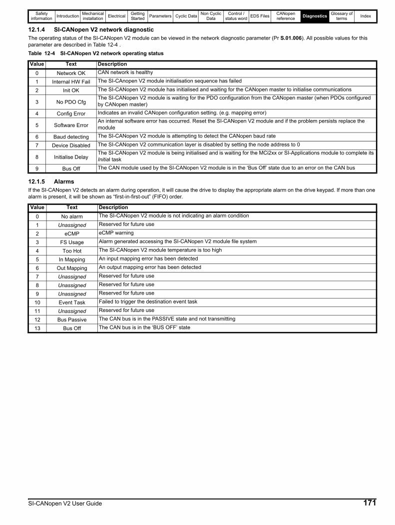
Safety information Introduction Mechanical
installation Electrical Getting Started Parameters Cyclic Data Non Cyclic
DataControl /
status word EDS Files CANopen reference Diagnostics Glossary of
terms Index
12.1.4 SI-CANopen V2 network diagnosticThe operating status of the SI-CANopen V2 module can be viewed in the network diagnostic parameter (Pr S.01.006). All possible values for this parameter are described in Table 12-4 .Table 12-4 SI-CANopen V2 network operating status
12.1.5 AlarmsIf the SI-CANopen V2 detects an alarm during operation, it will cause the drive to display the appropriate alarm on the drive keypad. If more than one alarm is present, it will be shown as “first-in-first-out” (FIFO) order.
Value Text Description0 Network OK CAN network is healthy
1 Internal HW Fail The SI-CAnopen V2 module initialisation sequence has failed
2 Init OK The SI-CANopen V2 module has initialised and waiting for the CANopen master to initialise communications
3 No PDO CfgThe SI-CANopen V2 module is waiting for the PDO configuration from the CANopen master (when PDOs configured by CANopen master)
4 Config Error Indicates an invalid CANopen configuration setting. (e.g. mapping error)
5 Software ErrorAn internal software error has occurred. Reset the SI-CANopen V2 module and if the problem persists replace the module
6 Baud detecting The SI-CANopen V2 module is attempting to detect the CANopen baud rate
7 Device Disabled The SI-CANopen V2 communication layer is disabled by setting the node address to 0
8 Initialise DelayThe SI-CANopen V2 module is being initialised and is waiting for the MCi2xx or SI-Applications module to complete its Initial task
9 Bus Off The CAN module used by the SI-CANopen V2 module is in the ‘Bus Off’ state due to an error on the CAN bus
Value Text Description0 No alarm The SI-CANopen V2 module is not indicating an alarm condition
1 Unassigned Reserved for future use
2 eCMP eCMP warning
3 FS Usage Alarm generated accessing the SI-CANopen V2 module file system
4 Too Hot The SI-CANopen V2 module temperature is too high
5 In Mapping An input mapping error has been detected
6 Out Mapping An output mapping error has been detected
7 Unassigned Reserved for future use
8 Unassigned Reserved for future use
9 Unassigned Reserved for future use
10 Event Task Failed to trigger the destination event task
11 Unassigned Reserved for future use
12 Bus Passive The CAN bus is in the PASSIVE state and not transmitting
13 Bus Off The CAN bus is in the ‘BUS OFF’ state
SI-CANopen V2 User Guide 171

Safety information Introduction Mechanical
installation Electrical Getting Started Parameters Cyclic Data Non Cyclic
DataControl /
status word EDS Files CANopen reference Diagnostics Glossary of
terms Index
172 SI-CANopen V2 User Guide
13 Glossary of termsAddress: This is the unique network identification given to a networked device to allow communication on a network. When a device sends or receives data the address is used to determine the source and the destination of the message.
Alignment: By default SI-CANopen V2 transmits values as 32 bits on the network. It is possible by using alignment to reduce the number of bits transmitted when sending 16-bit (or smaller) values on the network to 16-bit (32-bit values will still be transmitted as 32-bit values). This has the advantage of reducing the volume of traffic on the network and allowing more parameters to be mapped within SI-CANopen V2.
Bit: A binary digit, this may have the value of 1 or 0.
Byte: A collection of 8 binary digits that collectively store a value. This may be signed or unsigned.
CAN: The base network used for CANopen. The CANopen module does not support CAN commands.
CANopen: Builds on the basic CAN protocol by offering higher level functionality.
Casting: The process of changing between data sizes without changing the value represented, e.g. changing from 16-bit to 32-bit.
Consistency: Describes how data is transmitted between nodes on the network. If data is consistent it is transmitted from node to node as a single entity. Thus preventing data corruption where multiple bytes are transmitted or received individually.
Control word: A collection of binary digits that are used to control the drive. Features typically include directional controls, run controls and other similar functions.
Cyclic data: This consists of values that are sent at regular or cyclic intervals across the network. A typical use of cyclic data would be the transmission of a speed reference or a control word.
Data format: Determines the quantity and function of the data sent and received across the network.
Data rate: Determines the communication speed of the network, the higher the value the more data can be sent across the network in the same time period.
Device: A piece of equipment connected to a network, this may be any type of equipment including repeaters, hubs, masters or slaves.
Double word: A 32-bit word, this may be signed or unsigned.
Earthing/Grounding: Describes the electrical safety or shielding connections for the module.
Event task: A special way to use a message or change of state to trigger a software routine.
IN data: Data that is returned from a slave device to the CANopen master.
Long word: A 32-bit data word that may be signed or unsigned.
Mapping: The process of linking CANopen values to parameters within the drive.
Master: The controlling device on the network, generally this will include programming features.
Network Loss Trip: A method to determine when a node has lost contact with the master.
Node: A device on the network. This may be either a device such as a drive or part of the network such as a repeater.
Non-Cyclic Data: Data that is requested or sent by the master as required. This is not sent on a regular basis and generally allows access to any parameter. This is useful for occasional changes or configuration purposes.
Object Dictionary: A collection of the objects that are supported by the product.
Poll rate: The rate at which cyclic data is sent and received on the network.
Response ID: The response code of the message received when using PPO4 word non-cyclic communication.
Scan rate: See Poll rate in this section.
Shielding: A connection to provide additional immunity to noise used on a network cable.
Segment: An electrically separate part of the network. Each segment requires correct termination to ensure reliable operation. Due to electrical limitations the maximum number of devices on a segment is limited to 32.
Slave: A device on the CANopen network such as a drive or sensor. A slave device will only respond to messages from a master.
Status word: A value that denotes the status of the drive. Each bit within the word will have a specific meaning.
Task ID: The code used to describe the purpose of a message using PPO 4 word non-cyclic communication.
Termination: This is used at both ends of a network segment to prevent reflections and reduce noise.
Watchdog: A method used to determine if a communication system is ok/healthy. A typical watchdog scheme uses a handshaking system to check both the master and slave are participating in communications.
Word: A collection of 16 binary digits.

IndexAAbove set speed .....................................................................77Activate bit timing ..................................................................121At speed ..................................................................................77
BBasic data types ......................................................................81Below set speed ......................................................................77Blank mapping parameters .....................................................72
CCautions ....................................................................................5Changing data rate ................................................................121Changing PDO mapping parameters ......................................72COB-ID EMCY ........................................................................89COB-ID SYNC .........................................................................87Communication profile objects ................................................81Configure bit timing ...............................................................121Configure node-ID .................................................................121Control word ............................................................................76Conversion factors ................................................................128Current limit .............................................................................77
DDefault parameters - restore ...................................................88Device ...................................................................................128Device profiles .......................................................................128DeviceNet ground point ...........................................................13Drive active .............................................................................77Dynamic brake active ..............................................................77
EEmergency object .................................................................124Emergency object state .........................................................127Emergency object state transitions .......................................127Enable DSP402 device profiles .............................................128Error register ...........................................................................86
FFlexible PDO numbering .........................................................92
GGeneral installation .................................................................11Generic EDS files ....................................................................79
HHardware enable .....................................................................76
IIdentity object ..........................................................................90
LLayer setting services (LSS) .................................................119
MManufacturer device name ..................................................... 87Manufacturer hardware version .............................................. 87Manufacturer software version ............................................... 87Manufacturer status register ................................................... 86Maximum network length ........................................................ 13Minimum node to node cable length ....................................... 13Modbus channel ................................................................... 127Mode 1 - CT single word mode .............................................. 75
NNetwork management objects (NMT) ................................... 118NMT commands ................................................................... 119
OOperating states ..................................................................... 90
PParameter data object mapping ........................................... 128PDO data mapping errors ....................................................... 72Pre-defined error field ............................................................. 86Process data object (PDO) ..................................................... 72Producer heartbeat time ......................................................... 90Profile torque mode .............................................................. 142Profiles .................................................................................... 72
RRegenerating .......................................................................... 77Running at or below minimum speed ..................................... 77RxPDO COB-ID ...................................................................... 96RxPDO communication parameters ....................................... 95RxPDO event timer ................................................................. 97RxPDO event triggers ........................................................... 109RxPDO inhibit time ................................................................. 97RxPDO mapping parameters ................................................. 98RxPDO transmission type ...................................................... 96RxPDO, SYNC and missed heartbeat event handling ......... 102
SSDO abort codes .................................................................... 75Select product code .............................................................. 120Select revision number ......................................................... 120Select serial number ............................................................. 120Select vendor ID ................................................................... 120Service data object (SDO) ...................................................... 74Set-up flow chart ..................................................................... 24SI-DeviceNet cable shield connections .................................. 12Spurs ...................................................................................... 13Status word ............................................................................. 77Status word bit functions ........................................................ 77Switch mode global .............................................................. 120Switch mode selective .......................................................... 120
SI-CANopen V2 User Guide 173

Ttarget_torque .........................................................................142Termination .............................................................................12torque_actual_value ..............................................................143torque_profile_type ...............................................................143torque_slope .........................................................................143TxPDO COB-ID .....................................................................100TxPDO communication parameters ........................................99TxPDO inhibit time ................................................................100TxPDO mapping parameters ................................................101TxPDO number configuration .................................................94TxPDO transmission type .....................................................100
UUnused PDO data channels ...................................................72
VVelocity mode objects ...........................................................144vl_control_effort ....................................................................145
ZZero speed ..............................................................................77
174 SI-CANopen V2 User Guide


0478-0101-03
Related Documents