Model 5100e 100 mm graphics recorder User guide E UR O T H E R M

Welcome message from author
This document is posted to help you gain knowledge. Please leave a comment to let me know what you think about it! Share it to your friends and learn new things together.
Transcript

Model
5100e
10
0 m
m g
raphic
s re
cord
er
User guide
EUROTHERM


Declaration of Conformity
Manufacturer's name: Eurotherm Limited
Manufacturer's address Faraday Close, Worthing, West Sussex,BN13 3PL, United Kingdom.
Product type: Industrial graphics recorder
Models: 5100e Status level A1 and above
Safety specification: EN61010-1: 1993 / A2:1995
EMC emissions specification: EN61326
EMC immunity specification: EN61326
εEUROTHERM
Eurotherm Limited hereby declares that the above products conform to the safety and EMCspecifications listed. Eurotherm Limited further declares that the above products complywith the EMC Directive 89 / 336 / EEC amended by 93 / 68 / EEC, and also with the LowVoltage Directive 73 /23 / EEC
Signed for and on behalf of Eurotherm LimitedPeter de la Nougerde(Technical Director)
Signed: Dated:
IA249986U580 Issue 1 Jan 2001
© 2003 Eurotherm Limited
All rights are strictly reserved. No part of this document may be reproduced, modified, or transmitted in any formby any means, nor may it be stored in a retrieval system other than for the purpose to act as an aid in operating theequipment to which the document relates, without the prior written permission of Eurotherm limited.
Eurotherm Limited pursues a policy of continuous development and product improvement. The specifications inthis document may therefore be changed without notice. The information in this document is given in good faith,but is intended for guidance only. Eurotherm Limited will accept no responsibility for any losses arising fromerrors in this document.

100 MM GRAPHICS RECORDER: USER GUIDE
User GuidePage 1
HA027271Issue 10 Jun 03
GRAPHICS RECORDER
USER MANUAL
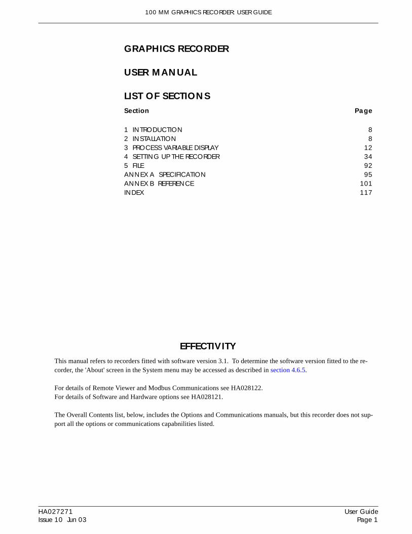
LIST OF SECTIONSSection Page
1 INTRODUCTION 82 INSTALLATION 83 PROCESS VARIABLE DISPLAY 124 SETTING UP THE RECORDER 345 FILE 92ANNEX A SPECIFICATION 95ANNEX B REFERENCE 101INDEX 117
EFFECTIVITYThis manual refers to recorders fitted with software version 3.1. To determine the software version fitted to the re-corder, the 'About' screen in the System menu may be accessed as described in section 4.6.5.
For details of Remote Viewer and Modbus Communications see HA028122.For details of Software and Hardware options see HA028121.
The Overall Contents list, below, includes the Options and Communications manuals, but this recorder does not sup-port all the options or communications capabnilities listed.

100 MM GRAPHICS RECORDER: USER GUIDE
HA027271Issue 10 Jun 03
User GuidePage 2
GRAPHICS RECORDER
USER MANUAL
LIST OF CONTENTSSection PageSafety Notes ....................................................................................................... 7SYMBOLS USED ON THE RECORDER LABELLING .................................................. 71 INTRODUCTION ................................................................................. 81.1 UNPACKING THE RECORDER ....................................................................... 82 INSTALLATION ................................................................................... 82.1 MECHANICAL INSTALLATION ...................................................................... 82.2 ELECTRICAL INSTALLATION .......................................................................... 10
2.2.1 Signal wiring ....................................................................................... 10CONNECTOR WIRING DETAILS ........................................................... 10
2.2.2 Supply voltage wiring ............................................................................ 11LINE SUPPLY ........................................................................................ 11LOW VOLTAGE SUPPLY OPTION .......................................................... 11
2.3 DISK INSERTION AND REMOVAL ................................................................. 113 PROCESS VARIABLE DISPLAY .............................................................. 12
TRUNCATION OF NUMERIC VALUES .................................................... 13CURRENT CHANNEL ALARM ICONS .................................................... 13
3.1 STATUS BAR ................................................................................................ 133.1.1 Current access level ............................................................................. 133.1.2 Page name .......................................................................................... 133.1.3 Alarm indicators .................................................................................. 14
ALARM SUMMARY PAGE ..................................................................... 14ALARM ACKNOWLEDGEMENT ............................................................ 15INSTRUMENT ALARMS ........................................................................ 16CHANNEL ALARM ............................................................................... 17CHANGE BATTERY .............................................................................. 17
3.1.4 Disk icon ............................................................................................. 173.1.5 FTP Icon .............................................................................................. 17
3.2 NAVIGATION Keys ...................................................................................... 183.2.1 Key functions ....................................................................................... 18
MESSAGE LOG ................................................................................... 193.3 FIRST SWITCH-ON ....................................................................................... 21
3.3.1 Access to Configuration ........................................................................ 22TEXT STRING ENTRY ............................................................................ 23
3.4 DISPLAY MODES .......................................................................................... 253.4.1 Vertical Trend display ........................................................................... 25
TIME CHANGE RECORDS .................................................................... 26TREND HISTORY .................................................................................. 26
3.4.2 Horizontal Trend display ....................................................................... 283.4.3 Vertical bargraph .................................................................................. 303.4.4 Horizontal bargraph ............................................................................ 313.4.5 Numeric .............................................................................................. 32
3.5 OPERATOR NOTES ...................................................................................... 33

100 MM GRAPHICS RECORDER: USER GUIDE
User GuidePage 3
HA027271Issue 10 Jun 03
4 SETTING UP THE RECORDER ............................................................... 344.1 ARCHIVE ..................................................................................................... 35
4.1.1 Archive to disk ..................................................................................... 354.1.2 Remote archiving (FTP transfer) .............................................................. 36
4.2 SAVE / RESTORE ......................................................................................... 374.2.1 Save ................................................................................................... 38
SAVE FOR PRE VERSION 1.8 ................................................................ 384.2.2 Restore................................................................................................ 384.2.3 New ................................................................................................... 384.2.4 Text .................................................................................................... 384.2.5 Import User Linearisation ...................................................................... 394.2.6 Export User Linearisation ...................................................................... 39
4.3 CONFIGURATION ........................................................................................ 404.3.1 Instrument configuration ........................................................................ 43
INSTRUMENT NAME ........................................................................... 43NORMAL/SAVER DISPLAY .................................................................... 43SAVE AFTER ........................................................................................ 43MODBUS ADDRESS ............................................................................. 43MODBUS SECURITY DISABLED ............................................................. 43COMMS CHANNEL TIMEOUT .............................................................. 43PRESET HOUR ..................................................................................... 43PRESET MINUTE .................................................................................. 43
4.3.2 Group configuration ............................................................................. 44GROUP NUMBER ................................................................................ 44TREND UNITS...................................................................................... 44DESCRIPTOR ....................................................................................... 44A/B SWITCHING ................................................................................ 44TREND SPEED/TREND INTERVAL ........................................................... 45GRID TYPE .......................................................................................... 45RECORDING ENABLE .......................................................................... 46RECORDING SPEED/RECORDING INTERVAL ......................................... 46TREND HISTORY DURATION ................................................................ 46ARCHIVE TO MEDIA/ARCHIVE VIA FTP ................................................. 46ALARM MESSAGE ............................................................................... 46ACK MESSAGE ................................................................................... 47GROUP CONTENTS ............................................................................ 47
4.3.3 Channel/Alarm configuration................................................................ 48CHANNEL NUMBER ............................................................................ 49VALUE ................................................................................................ 49INPUT TYPE ......................................................................................... 49LIN TYPE ............................................................................................. 49INPUT LOW ........................................................................................ 49INPUT HIGH........................................................................................ 49SHUNT ............................................................................................... 49RANGE LOW ...................................................................................... 50RANGE HIGH ..................................................................................... 50RANGE UNITS .................................................................................... 50SCALED .............................................................................................. 50OFFSET ............................................................................................... 50SCALE TYPE ........................................................................................ 50FILTER ................................................................................................. 51BREAK RESPONSE ............................................................................... 52COLD JUNCTION COMPENSATION (CJC) ............................................ 52DESCRIPTOR ....................................................................................... 52A/B SWITCHING ................................................................................ 52SPANNED ........................................................................................... 52ZONE................................................................................................. 53PV FORMAT ........................................................................................ 53
LIST OF CONTENTS (Cont.)Section Page
Cont...

100 MM GRAPHICS RECORDER: USER GUIDE
HA027271Issue 10 Jun 03
User GuidePage 4
LIST OF CONTENTS (Cont.)Section Page4.3.3 Channnel/Alarm Configuration (Cont.)
Cont...
MAXIMUM DECIMAL DIGITS ................................................................ 53COLOUR ............................................................................................ 53ALARM NUMBER ................................................................................. 54ENABLE .............................................................................................. 54TYPE ................................................................................................... 54PARAMETERS ...................................................................................... 55EXAMPLE ............................................................................................ 55JOB NUMBER ...................................................................................... 57CATEGORY ......................................................................................... 57WHILE/ON......................................................................................... 57ALARM MESSAGES ............................................................................. 57
4.3.4 Views Configuration ............................................................................. 58HOME TIMEOUT ................................................................................. 58HOME GROUP .................................................................................... 58DARK TREND/DARK HISTORY BACKGROUND ...................................... 58SCOPE ............................................................................................... 59GROUP............................................................................................... 59DISPLAY ENABLED ............................................................................... 59HOME PAGE ....................................................................................... 59DISPLAY MODE ENABLING .................................................................. 59
4.3.5 Archive configuration ........................................................................... 60COMPRESSION .................................................................................. 61FLASH SIZE ......................................................................................... 61SHORTEST TREND HISTORY / DURATION ............................................. 61SHOW ............................................................................................... 61ARCHIVE TO MEDIA ............................................................................ 61MEDIA FULL OPERATION ..................................................................... 61MEDIA SIZE ........................................................................................ 62DISK ARCHIVE CAPACITY .................................................................... 62MEDIA FULL EVENT LIMIT ..................................................................... 62ARCHIVE TO REMOTE ......................................................................... 62REMOTE PATH ..................................................................................... 62PRIMARY REMOTE HOST ..................................................................... 62PRIMARY LOGIN NAME/PASSWORD ................................................... 62SECONDARY REMOTE HOST/LOGIN/PASSWORD ............................... 62
4.3.6 Event configuration .............................................................................. 63EVENT NUMBER.................................................................................. 63SOURCE TYPES ................................................................................... 63SOURCE 1 SENSE ............................................................................... 64OPERATOR.......................................................................................... 64SOURCE 2 SENSE ............................................................................... 64DESCRIPTOR ....................................................................................... 65JOB NUMBER ...................................................................................... 65CATEGORY ......................................................................................... 65WHILE/ON......................................................................................... 65EVENT EXAMPLE ................................................................................. 65
4.3.7 Messages ............................................................................................ 66MESSAGE ENTRY ................................................................................ 66CONFIGURABLE PARAMETERS ............................................................. 66EXAMPLE ............................................................................................ 67
4.3.8 User Linearisation Tables ....................................................................... 68CONFIGURATION PARAMETERS .......................................................... 68
4.3.9 Options............................................................................................... 70

100 MM GRAPHICS RECORDER: USER GUIDE
User GuidePage 5
HA027271Issue 10 Jun 03
4.4 SECURITY .................................................................................................... 714.4.1 Access levels ....................................................................................... 71
SETTING PERMISSIONS ....................................................................... 72ACCESS WHEN: ................................................................................. 72NEW PASSWORD/RETYPE PASSWORD ................................................ 72CONNECT FROM REMOTE .................................................................. 72REMOTE USER NAME/PASSWORD ...................................................... 73LOGIN DISABLED ................................................................................ 73EDIT OWN PASSWORD ...................................................................... 73CHANGE ALARM SETPOINTS .............................................................. 73ACKNOWLEDGE ALARMS ................................................................... 73EDIT MATHS CONSTANT ..................................................................... 73PRESET TOTALISERS ............................................................................. 73SET CLOCK ......................................................................................... 73ADJUST INPUTS ................................................................................... 73ARCHIVING CONTROL ........................................................................ 73SAVE/RESTORE ................................................................................... 74PASTE/DELETE FILES ............................................................................ 74FULL CONFIGURATION ....................................................................... 74FULL SECURITY .................................................................................... 74EVENT PERMISSION 1 ......................................................................... 74EVENT PERMISSION 2 TO 5 ................................................................ 74FORCE CHANGE OF PASSWORD ........................................................ 74
4.4.2 Add user ............................................................................................. 75NEW USER/NEW PASSWORD/RETYPE PASSWORD ............................. 75BASED ON ......................................................................................... 75
4.4.3 Remove user ........................................................................................ 754.5 NETWORK CONFIGURATION ...................................................................... 76
4.5.1 Address .............................................................................................. 76INSTRUMENT NUMBER/MAC ADDRESS ............................................... 76IP ADDRESS LOOKUP .......................................................................... 76BOOTP TIMEOUT ................................................................................ 76IP ADDRESS ........................................................................................ 76SUBNET MASK .................................................................................... 77DEFAULT GATEWAY ............................................................................. 77SNTP ENABLE ..................................................................................... 77SNTP SERVER ...................................................................................... 77
4.5.2 Name ................................................................................................. 78LOCAL HOST ...................................................................................... 78DOMAIN ............................................................................................ 78DOMAIN NAME SERVICE (DNS) .......................................................... 78PRIMARY/SECONDARY DNS SERVER ................................................... 78
4.6 SYSTEM ...................................................................................................... 794.6.1 Clock .................................................................................................. 804.6.2 Locale ................................................................................................. 804.6.3 Keycode .............................................................................................. 804.6.4 Input adjust ......................................................................................... 80
ADJUST PROCEDURE ........................................................................... 824.6.5 About ................................................................................................. 83
INSTRUMENT VARIANT ........................................................................ 83CONFIG VERSION .............................................................................. 83SECURITY VERSION ............................................................................. 83SUPPORT FILE ...................................................................................... 84
4.6.6 Copy .................................................................................................. 85CONFIGURABLE PARAMETERS ............................................................. 85COPY RULES ....................................................................................... 86
LIST OF CONTENTS (Cont.)Section Page
Cont...
100 MM GRAPHICS RECORDER: USER GUIDE
HA027271Issue 10 Jun 03
User GuidePage 6
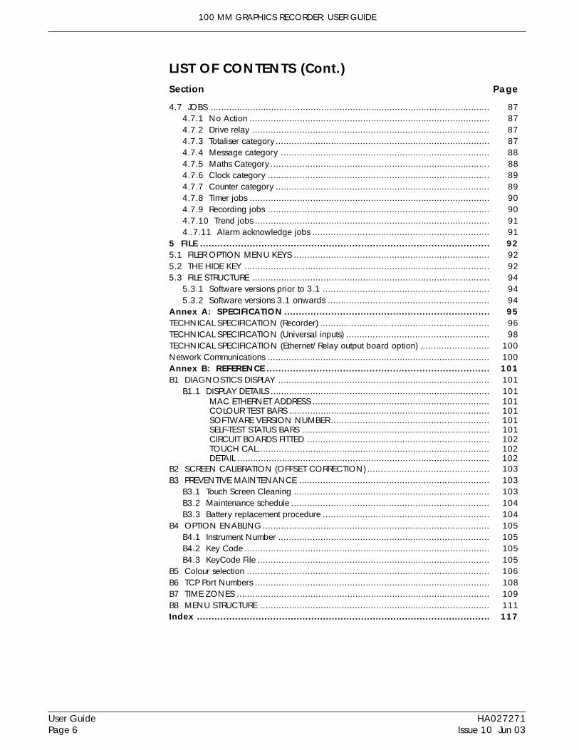
4.7 JOBS .......................................................................................................... 874.7.1 No Action ........................................................................................... 874.7.2 Drive relay .......................................................................................... 874.7.3 Totaliser category ................................................................................. 874.7.4 Message category ............................................................................... 884.7.5 Maths Category ................................................................................... 884.7.6 Clock category .................................................................................... 894.7.7 Counter category ................................................................................. 894.7.8 Timer jobs ........................................................................................... 904.7.9 Recording jobs .................................................................................... 904.7.10 Trend jobs ......................................................................................... 914..7.11 Alarm acknowledge jobs ................................................................... 91
5 FILE ................................................................................................... 925.1 FILER OPTION MENU KEYS .......................................................................... 925.2 THE HIDE KEY ............................................................................................. 925.3 FILE STRUCTURE .......................................................................................... 94
5.3.1 Software versions prior to 3.1 ............................................................... 945.3.2 Software versions 3.1 onwards ............................................................. 94
Annex A: SPECIFICATION...................................................................... 95TECHNICAL SPECIFICATION (Recorder) ................................................................ 96TECHNICAL SPECIFICATION (Universal inputs) ...................................................... 98TECHNICAL SPECIFICATION (Ethernet/Relay output board option) .......................... 100Network Communications .................................................................................... 100Annex B: REFERENCE ............................................................................ 101B1 DIAGNOSTICS DISPLAY ................................................................................ 101
B1.1 DISPLAY DETAILS ................................................................................... 101MAC ETHERNET ADDRESS ................................................................... 101COLOUR TEST BARS ............................................................................ 101SOFTWARE VERSION NUMBER ............................................................ 101SELF-TEST STATUS BARS ....................................................................... 101CIRCUIT BOARDS FITTED ..................................................................... 102TOUCH CAL........................................................................................ 102DETAIL ................................................................................................ 102
B2 SCREEN CALIBRATION (OFFSET CORRECTION) .............................................. 103B3 PREVENTIVE MAINTENANCE ........................................................................ 103
B3.1 Touch Screen Cleaning .......................................................................... 103B3.2 Maintenance schedule ........................................................................... 104B3.3 Battery replacement procedure ............................................................... 104
B4 OPTION ENABLING...................................................................................... 105B4.1 Instrument Number ................................................................................ 105B4.2 Key Code ............................................................................................. 105B4.3 KeyCode File ........................................................................................ 105
B5 Colour selection ............................................................................................ 106B6 TCP Port Numbers ......................................................................................... 108B7 TIME ZONES ................................................................................................ 109B8 MENU STRUCTURE ....................................................................................... 111Index .................................................................................................... 117
LIST OF CONTENTS (Cont.)Section Page

100 MM GRAPHICS RECORDER: USER GUIDE
User GuidePage 7
HA027271Issue 10 Jun 03
! Refer to the manual for instructions
Protective earth
This recorder for ac supply only
This recorder for dc supply only
This recorder for either ac or dc supply
Risk of electric shock
SAFETY NOTES
WARNINGAny interruption of the protective conductor inside or outside the apparatus, or disconnection of theprotective earth terminal is likely to make the apparatus dangerous under some fault conditions. Inten-tional interruption is prohibited.
Note: in order to comply with the requirements of safety standard BS EN61010, the recorder shall have oneof the following as a disconnecting device, fitted within easy reach of the operator, and labelled as the discon-necting device.
a A switch or circuit breaker which complies with the requirements of IEC947-1 and IEC947-3b. A separable coupler which can be disconnected without the use of a toolc. A separable plug, without a locking device, to mate with a socket outlet in the building.
1. Before any other connection is made, the protective earth terminal shall be connected to a protective conductor.The mains (supply voltage) wiring must be terminated within the connector in such a way that, should it slip inthe cable clamp, the Earth wire would be the last wire to become disconnected.
2. In the case of portable equipment, the protective earth terminal must remain connected (even if the recorder isisolated from the mains supply), if any of the I/O circuits are connected to hazardous voltages*.
3. The mains supply fuse within the power supply is not replaceable. If it is suspected that the fuse is faulty, themanufacturer's local service centre should be contacted for advice.
4. Whenever it is likely that protection has been impaired, the unit shall be made inoperative, and secured againstaccidental operation. The manufacturer's nearest service centre should be contacted for advice.
5. Any adjustment, maintenance and repair of the opened apparatus under voltage, should be avoided as far as possi-ble and, if inevitable, shall be carried out only by a skilled person who is aware of the hazard involved.
6. Where conductive pollution (e.g. condensation, carbon dust) is likely, adequate air conditioning/filtering/sealingetc. must be installed in the recorder enclosure.
7. Signal and supply voltage wiring should be kept separate from one another. Where this is impractical, shieldedcables should be used for the signal wiring.
8. If the equipment is used in a manner not specified by the manufacturer, the protection provided by the equipmentmight be impaired.
* A full definition of 'Hazardous' voltages appears under 'Hazardous live' in BS EN61010. Briefly, under normal op-erating conditions, hazardous voltages are defined as being > 30V RMS (42.2V peak) or > 60V dc.
SYMBOLS USED ON THE RECORDER LABELLINGOne or more of the symbols below may appear as a part of the recorder labelling.

100 MM GRAPHICS RECORDER: USER GUIDE
HA027271Issue 10 Jun 03
User GuidePage 8
USER MANUAL1 INTRODUCTION
This document describes the installation, operation and configuration of a 100mm graphics recorder. The recorderhas the facility for FTP transfer and Remote viewer connection if the Ethernet option is fitted.
The recorder instrument time can be updated from a unicast (i.e. point-to-point) Simple Network Time Protocol(SNTP) server and is also itself an SNTP server. SNTP time is based on elapsed seconds since 00:00 hrs on 1st Jan1900 GMT and is affected neither by time zones nor by daylight saving. The relevant TCP port number is 123. Seesections 4.3.1 (Instrument configuration), 4.5.1 (Network Address configuration) and B6 in Annex B, for more details.
1.1 UNPACKING THE RECORDER
The recorder is despatched in a special pack, designed to give adequate protection during transit. Should the outerbox show signs of damage, it should be opened immediately, and the recorder examined. If there is evidence of dam-age, the instrument should not be operated and the local representative contacted for instructions. After the recorderhas been removed from its packing, the packing should be examined to ensure that all accessories and documentationhave been removed. The packing should then be stored against future transport requirements.
2 INSTALLATION
2.1 MECHANICAL INSTALLATION
Figure 2.1 gives installation details.
Note: It is recommended that the rear face of the panel be centre-punched at suitable positions to locate thetips of the case clamps. Otherwise, particularly on smooth surfaces, the clamps can 'wander' as they aretightened, leading to inefficient clamping and possible damage to the recorder mounting slots.
The unit is inserted through the panel aperture from the front of the panel. With the weight of the recorder supported,a panel clamp is inserted into each of the mounting slots (one each on the left- and right-hand sides). The jackingscrews are then tightened sufficiently to clamp the recorder into position. EXCESS FORCE SHOULD NOT BEUSED IN TIGHTENING THESE SCREWS.

100 MM GRAPHICS RECORDER: USER GUIDE
User GuidePage 9
HA027271Issue 10 Jun 03
2 INSTALLATION (Cont.)
Figure 2.1 Mechanical installation details - small frame unit
247.5mm (9.75in) (STC)
213mm (8.39in)
13
7m
m (
5.4
in)
Mounting slot(Left hand side)
View on right handside
284mm (11.18in) (LTC closed)
70 m
m(2
.76
in)
399 mm (15.7in) (LTC open)
a˚ b˚
Ver
tical
MAXIMUM INSTALLED ANGLEa = b = 15 degrees max
Panel clamping
138 x 138mm(-0.0 + 1.0)
5.44 x 5.44 in(-0.00 + 0.04)
y
x
Panel cutout
x = 15mm (0.6 inch)y = 10 mm (0.4 in)
Minimum recommended spacingSide clamps Top/bottom clamps
x = 10 mm (0.4 in)y = 15mm (0.6 inch)
View on under side 137mm(5.4in)
110
mm
(4.
33 in
)
Max. 30mm(1.2 in)
Panel thickness(25.4mm (1 in) max)
Lift then pull to openflap for mass storage
access
144mm (5.67in)
144m
m (
5.67
in)
LTC = long terminal coverSTC = Short Terminal cover
100 MM GRAPHICS RECORDER: USER GUIDE
HA027271Issue 10 Jun 03
User GuidePage 10
com
nc
no
V+ V- I
+ -+ -
Shuntassembly
V+ V- I
+ -
V+ V- I
Attenuatorassembly
-20 to + 100 V dc-2 to + 10 V dcThermocouples
dc millivoltsDC milliamps
1 2 3 4 5 6 7 8 9 10 11 12 13 14 15 16 17 18 19 20 21 22
V+ V- I V+ V- I V+ V- ICold
junction V+ V- I V+ V- I V+ V- I
V+ V- I V+ V- I
2-wire resistancethermometer
3-wire resistancethermometer Potentiometer
V+ V- I
Contact closure(Not channel 1)
RTD RTD
V+ V- I
Potentiometer Minimum contact = 60msec
Input board pinouts
Channel 6Channel 4 Channel 5Channel 1 Channel 2 Channel 3
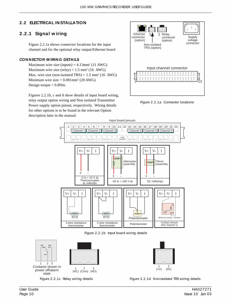
2.2 ELECTRICAL INSTALLATION
2.2.1 Signal wiring
Figure 2.2.1a shows connector locations for the inputchannel and for the optional relay output/Ethernet board
CONNECTOR WIRING DETAILSMaximum wire size (inputs) = 4.13mm2 (11 AWG)Maximum wire size (relay) = 1.5 mm2 (16 AWG)Max. wire size (non-isolated TRS) = 1.5 mm2 (16 AWG)Minimum wire size = 0.081mm2 (28 AWG)Design torque = 0.8Nm.
Figures 2.2.1b, c and d show details of input board wiring,relay output option wiring and Non isolated TransmitterPower supply option pinout, respectively. Wiring detailsfor other options is to be found in the relevant Optiondescription later in the manual.
Figure 2.2.1a Connector locations
Figure 2.2.1b Input board wiring details
18
Input channel connector
1 22
Supplyvoltage
connector
1Ethernetconnector
(option)
Relayconnector(option)
1
Non-isolatedTRS (option)
nc
Contacts shown inpower off/alarm
state
1
com
no
2 3
1(NC)
2(Com)
3(NO)
Figure 2.2.1c Relay wiring details Figure 2.2.1d Non-isolated TRS wiring details
1(+V)
2(0V)

100 MM GRAPHICS RECORDER: USER GUIDE
User GuidePage 11
HA027271Issue 10 Jun 03
2.2.2 Supply voltage wiring
WARNINGDC supply voltages must never be applied to recorders fitted with isolated transmitter power supplies.
Note: The minimum recommended wire size is 16/0.2 (0.5mm2).
LINE SUPPLYThe supply voltage to the recorder is terminated using an IEC socket which is connected to the mating plug at the rearof the recorder. The recorder is suitable for use with all ac voltages between 85 and 265 V RMS (47 to 63 Hz), andrequires 60 VA max. power. For recorders without transmitter supplies, supply voltages obetween 110V dc and 370V dc may also be used.
Figure 2.3a Disk access Figure 2.3b Disk eject
LOW VOLTAGE SUPPLY OPTIONNot suitable for recorders fitted with the isolated transmitter power supplyoption.The low voltage supply option is terminated at a three-pin connector (plugmounted on recorder - socket on supply cable) as shown in figure 2.2.2.The option allows the use of ac or dc supplies with the following charac-teristics:AC: 20 to 42V RMS (45 to 400 Hz)DC: 20 to 54V (See warning above)Power: 60VA max.
2.3 DISK INSERTION AND REMOVAL
The disk slot is located below the recorder screen, and is protected by a flap as shown in figure 2.1, above.
In order to access the disk slot, the bottom of the central part of the flap is lifted (figure 2.3a) and then used as a han-dle to pull the main flap open.
If a disk is already fitted, it is removed by pressing on the eject button (figure 2.3b).
Note: Before disk removal, archiving should be suspended (section 4.1) (wait for the green LED on the diskdrive to be extinguished), otherwise data might be lost.
+V or acEarth
0V or ac
Figure 2.2.2 Low voltage supply pinout
100 MM GRAPHICS RECORDER: USER GUIDE
HA027271Issue 10 Jun 03
User GuidePage 12
3 PROCESS VARIABLE DISPLAY
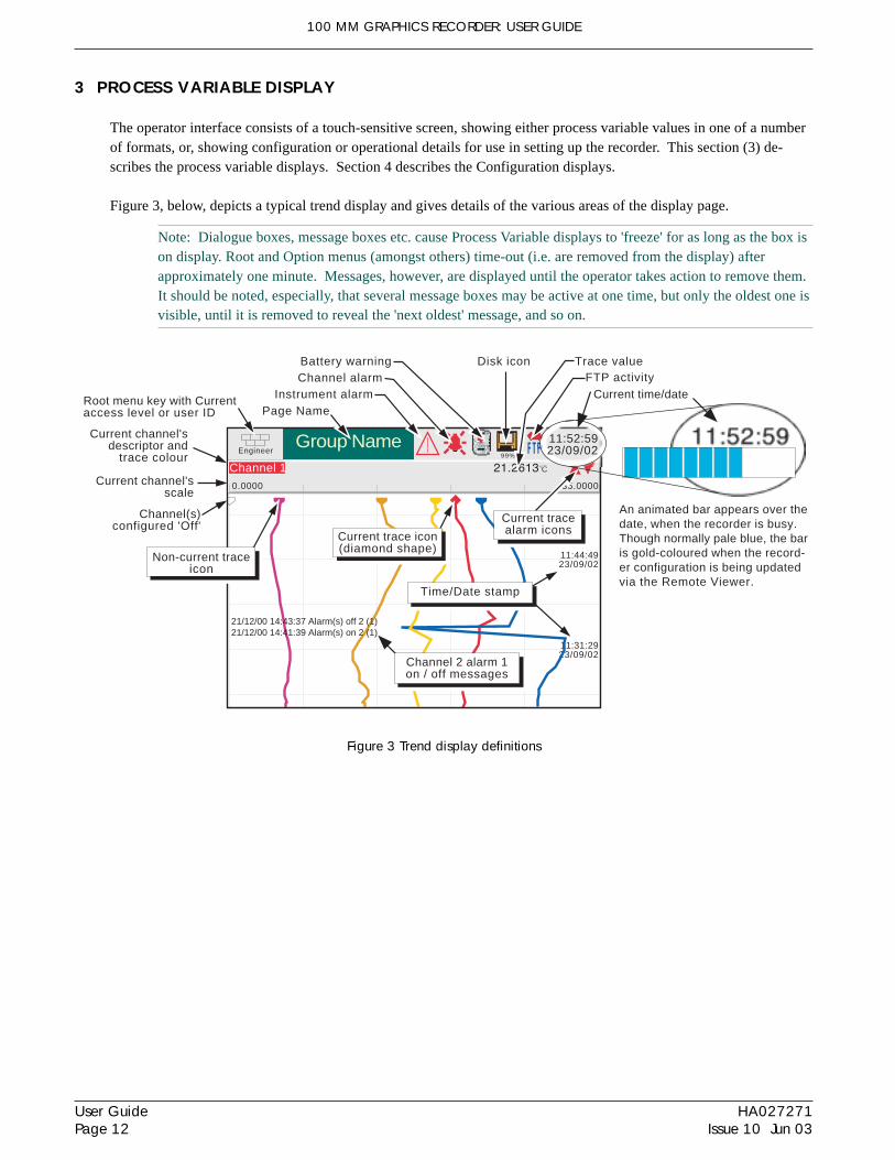
The operator interface consists of a touch-sensitive screen, showing either process variable values in one of a numberof formats, or, showing configuration or operational details for use in setting up the recorder. This section (3) de-scribes the process variable displays. Section 4 describes the Configuration displays.
Figure 3, below, depicts a typical trend display and gives details of the various areas of the display page.
Note: Dialogue boxes, message boxes etc. cause Process Variable displays to 'freeze' for as long as the box ison display. Root and Option menus (amongst others) time-out (i.e. are removed from the display) afterapproximately one minute. Messages, however, are displayed until the operator takes action to remove them.It should be noted, especially, that several message boxes may be active at one time, but only the oldest one isvisible, until it is removed to reveal the 'next oldest' message, and so on.
Figure 3 Trend display definitions
11:31:2923/09/02
EngineerGroup Name
99%
Channel 1 C
35.00000.0000
21/12/00 14:43:37 Alarm(s) off 2 (1)
11:44:4923/09/02
21/12/00 14:41:39 Alarm(s) on 2 (1)
Root menu key with Currentaccess level or user ID Page Name
Instrument alarmChannel alarmBattery warning
FTP activityCurrent time/date
Current channel'sdescriptor and
trace colour
Current channel'sscale
Channel(s)configured 'Off'
Disk icon
Channel 2 alarm 1on / off messages
11:52:5923/09/02
An animated bar appears over thedate, when the recorder is busy.Though normally pale blue, the baris gold-coloured when the record-er configuration is being updatedvia the Remote Viewer.
Trace value
Time/Date stamp
Current tracealarm iconsCurrent trace icon
(diamond shape)Non-current trace
icon

100 MM GRAPHICS RECORDER: USER GUIDE
User GuidePage 13
HA027271Issue 10 Jun 03
3 PROCESS VARIABLE DISPLAY (Cont.)
TRUNCATION OF NUMERIC VALUESIf the amount of space on the display page is insufficient to display the full width of the process variable or scalevalue, then the displayed value is rounded down and the number of decimal places reduced. If the available space isstill too restricted, the value is displayed in 'Scientific' format, or if this is still too wide, the final visible character ofthe integer part of the display is replaced by a '?'.
CURRENT CHANNEL ALARM ICONSIn each of the different types of PV display, each channel's faceplate give the status of the channel's alarms. Thisstatus is shown by one of the icons depicted in table 3, either off, flashing (if it is active and unacknowledged) or oncontinuously (if it is active and acknowledged). See section 3.1.3, below, for a description of how to acknowledgealarms, and section 4.3.3 for a description of the alarm types.
Note: for software versions 2.3 onwards, 32MB versions of the recorder come with four alarms per point,instead of two per point as supplied with previous software versions. In order to keep the total width used thesame for both versions, the icons for recorders with four alarms per point are half the width of icons forrecorders with two alarms per point. 16MB recorders are still supplied with two alarms per point. TheSystem/About display can be used establish what size of DRAM s fitted - see section 4.6.5.
Absolute High
Absolute Low
Deviation in
Deviation out
Rate-of-change Rising
Rate-of-change Falling
4-alarm units 2-alarm units
Table 3 Alarm symbols
3.1 STATUS BAR
This appears across the top of the display, and contains the items described below.
3.1.1 Current access level
There are four access levels available (Logged out, Operator, Engineer and Service), and the current level is displayedin this key at the top left hand corner of the display. Touching this key calls the root menu as described in section3.2.1 (Key functions) below. If 'user IDs' have been entered in the 'Add User' part of the Security setup, then the cur-rent user Id is displayed instead of the access level.
3.1.2 Page name
Initially this shows the current group's descriptor. The name changes according to context for example 'Operator' or'Config-Archive'.
100 MM GRAPHICS RECORDER: USER GUIDE
HA027271Issue 10 Jun 03
User GuidePage 14
Instrument Alarm Summary
Display Contrast
Alarm & Message options
Ack all Alarms
Alarm Summary
Message Log
Instrument Alarm Summary
Ok
Maths channel Failurenetwork boot failure
Ack all AlarmsConfirm acknowledge of alarms?
NoYes
1 (1) Water temp 1a 60.0000 68.5277 C
2 (1) Water temp 1b 30.0000 23.4531 C
2 (2) Water temp 1b 10.0000 15.7773 C
3 (1) 0il pressure 250.0000 260.3425PSI4 (1) Transfer 15.3678
Channel no.(alarm no.)
Channel descriptor
Alarm type symbol
Alarm Summary
Setpoint value(Absolute alarms only)
Current process value
Group 1Group 2
Goto GroupThe 'Goto Group' win-dow does not appear
for single grouprecorders.
Ack AlarmConfirm acknowledge of alarm?
NoYes
Touch Alarm area(e.g. channel alarm symbol)
Touch alarm to call 'Acknowledge'
dialogue box.
See section 3.2.1 forMessage Log details
3.1.3 Alarm indicators
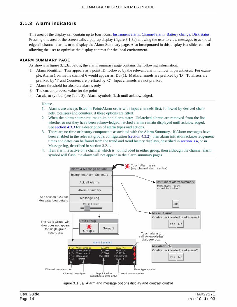
This area of the display can contain up to four icons: Instrument alarm, Channel alarm, Battery change, Disk status.Pressing this area of the screen calls a pop-up display (figure 3.1.3a) allowing the user to view messages to acknowl-edge all channel alarms, or to display the Alarm Summary page. Also incorporated in this display is a slider controlallowing the user to optimise the display contrast for the local environment.
ALARM SUMMARY PAGEAs shown in figure 3.1.3a, below, the alarm summary page contains the following information:1. Alarm identifier. This appears as a point ID, followed by the relevant alarm number in parentheses. For exam-
ple, Alarm 1 on maths channel 6 would appear as: D6 (1). Maths channels are prefixed by 'D'. Totalisers areprefixed by 'T' and Counters are prefixed by 'C'. Input channels are not prefixed.
2 Alarm threshold for absolute alarms only3 The current process value for the point4 An alarm symbol (see Table 3). Alarm symbols flash until acknowledged.
Notes:1. Alarms are always listed in Point/Alarm order with input channels first, followed by derived chan-
nels, totalisers and counters, if these options are fitted.2 When the alarm source returns to its non-alarm state: Unlatched alarms are removed from the list
whether or not they have been acknowledged; latched alarms remain displayed until acknowledged.See section 4.3.3 for a description of alarm types and actions.
3. There are no time or history components associated with the Alarm Summary. If Alarm messages havebeen enabled in the relevant group's configuration (section 4.3.2), then alarm initiation/acknowledgementtimes and dates can be found from the trend and trend history displays, described in section 3.4, or inMessage log, described in section 3.2.1.
4. If an alarm is active on a channel which is not included in either group, then although the channel alarmsymbol will flash, the alarm will not appear in the alarm summary pages.
Figure 3.1.3a Alarm and message options display and contrast control

100 MM GRAPHICS RECORDER: USER GUIDE
User GuidePage 15
HA027271Issue 10 Jun 03
3.1.3 ALARM INDICATORS (Cont.)
ALARM ACKNOWLEDGEMENTAlarms can be acknowledged globally (all alarms), individually or on a group basis.
ALL ALARMSTo acknowledge all active alarms, touch (e.g.) the channel alarm icon at the top of the screen. From the resulting pop-up menu, select 'Ack all Alarms', then finally, touch 'Yes' in the resulting pop-up confirmation box. Figure 3.1.3a,above, attempts to show this process.
INDIVIDUAL ALARMSIndividual alarms are acknowledged from the alarm summary page by touching the relevant item (highlights yellow),then touching 'Yes' in the resulting pop-up confirmation box. Figure 3.1.3a, above, attempts to show this process.
GROUP ALARMSFor recorders with multiple groups, alarms can be acknowledged on a group basis by calling the alarm summary pagefor the relevant group, then pressing the Root menu Options key (section 3.2), the 'Ack Group Alarms' key and finally,'Yes' in the resulting pop-up confirmation box. Figure 3.1.3b, below, attempts to show this process.
Figure 3.1.3b Group Alarm acknowledgement
1 (1) Water temp 1a 60.0000 68.5277 C
2 (1) Water temp 1b 30.0000 23.4531 C
2 (2) Water temp 1b 10.0000 15.7773 C
3 (1) 0il pressure 250.0000 260.3425PSI4 (1) Transfer 15.3678
Alarm Summary
Engineer
Options
Goto Group
Operator
Login
Goto View
Home
File
Root menu
Note
Ack Group Alarms
Option menu
Ack Group AlarmsConfirm acknowledge of alarm?
NoYes
100 MM GRAPHICS RECORDER: USER GUIDE
HA027271Issue 10 Jun 03
User GuidePage 16
3.1.3 ALARM INDICATORS (Cont.)
INSTRUMENT ALARMS This indicator appears, flashing, if any of the following alarms are active. The Instrument alarm summary page, de-scribed above, allows the user to view any such alarms.
Archive failed -(message) Message explains archive failure - due to disk being missing, write protected,faulty, full etc.
Battery-backed RAM cleared This message appears if the battery has failed, and the unit has been switched off.
Channel failure Indicates a hardware failure in the input channel circuit
Channel error Indicates a hardware failure in the channel circuit or in the internal CJ temperaturemeasurement
Clock failure Internal clock was corrupt at power up, or the time has never been set. Can becaused by battery failure, in which case the battery icon will also be visible. Theerror is cleared by setting the time and date. Server time forced to 00:00 1/1/1900.
Floppy disk worn Appears if a number of attempts had to be made before write to the disk was suc-cessful. No data is lost, but the disk should be replaced as soon as is practicable.
Floppy disk corrupt This appears if all attempts to write to the disk fail. In such a case, some data maybe lost. If the damaged area of the disk is in the system part of the disk, it mightappear to the recorder that it is unformatted, and the disk icon will disappear. Thedisk should be replaced immediately.
FTP Primary Server Failure This error is set if the recorder fails, after two attempts, to establish communica-tions with the primary server as defined in Archive Configuration (section 4.3.5).After the second attempt has failed, the Secondary server is tried.
FTP Secondary Server Failure This error is set if the recorder fails, after two attempts, to establish communica-tions with the secondary server as defined in Archive Configuration (section 4.3.5).See also 'FTP Primary Server Failure, above.
Insufficient non-volatile memory... There is insufficient memory available for the configuration. Sometimes caused bythe use of the Rolling Average maths function.
Internal flash: \user\ required repair Error found (in the internal file system) at power-up, and corrected.
Internal flash: \system\ required repair Error found (in the internal file system) at power-up, and corrected.
Internal flash: \history\ required repair Error found (in the internal file system) at power-up, and corrected.
Maths Channel failure Appears, for example, if the divisor of a divide function passes through zero.
Network boot failure The recorder is unable to establish connection with the bootP server. This might becaused by, for example, cable failure, network hardware failure, etc.
Recording failure - (message) Message explains recording failure e.g. file error, internal overflow etc.
Removable media failure This error is set if the disk is corrupt, wrongly formatted etc. Becomes active onlywhen an Archive is attempted.
Removable media full Floppy disk or PC card full. Becomes active only when an Archive is in progress.
SNTP server failure This alarm is set if:-a) the year received from the server is < 2001 or > 2035 orb) the configured SNTP server cannot be accessed
Time synchronisation failure Set if 5 or more 'Time change events' are caused by the SNTP server within 24 hrs.A 'Time change event' is defined as occuring whenever the recorder time is foundto be more than 2 seconds different from the server time. The alarm does not ap-pear until 24 hours after the first of the five-or-more Time Change events occurred.

100 MM GRAPHICS RECORDER: USER GUIDE
User GuidePage 17
HA027271Issue 10 Jun 03
3.1.3 ALARM INDICATORS (Cont.)
CHANNEL ALARMThis red 'bell' indicator appears if any channel is in alarm. The symbol is illuminated continuously if all alarms areacknowledged or flashes if any active alarm is unacknowledged. Refer to ALARM ACKNOWLEDGEMENT, above,for details of how to acknowledge alarms.
Note: If a point is in alarm, but not enabled in either group, the point's alarm symbol will behave as describedabove, but the alarm will not appear in the Alarm Summary displays. Such channels can be acknowledgedonly by using Ack All Alarms as described in section 3.1.2, above.
CHANGE BATTERYThis flashing indicator first appears when the battery voltage indicates that the battery is approaching the end of itsuseful life. The indicator continues to flash until the battery is replaced (Annex B, section B3.2). The indicator doesnot appear if the battery is not fitted.
3.1.4 Disk icon
This shows the free space available on the disk. The disk icon appears soon after a disk is inserted.
Only archiving activity is indicated; during archiving, the central area of the disk icon flashes green, regularly. Noother disk activity is indicated.
Figure 3.1.4 Archive activity indication
3.1.5 FTP Icon
For those recorders fitted with Ethernet option, the File Transfer Protocol (FTP) icon appears to the right of the discicon position, whenever transfer activity is taking place.
This area of the icon flashesgreen/white during archive.

100 MM GRAPHICS RECORDER: USER GUIDE
HA027271Issue 10 Jun 03
User GuidePage 18
3.2.1 Key functions
Close folder Used, where appropriate, to recall the previous (higher level) display page.
Open folder Used, where appropriate, to call a further (lower level) display page.
Left cursor Used to navigate backwards through a text string, when editing.
Right cursor Used to navigate forwards through a text string, when editing.
Root Calls the 'Root Menu' as shown.
ROOT MENU KEYSHome Causes a return to the 'Home' page from any page in the recorder. As delivered, the 'Home' page is the
vertical trend display as depicted in figure 3, but this can be edited (in Operator/Config - Views) to be anyof the available display modes - Horizontal trend, Vertical bargraph, Horizontal bargraph, Numeric etc.
Operator Causes the top level Operator page to appear. The appearance of this display is dictated by the securitylevel that the recorder is set to, and by the access level of the user. As despatched from the factory, therecorder is in 'logged out' mode and the Operator page contains only the buttons labelled 'Archive', 'Secu-rity' and System. Further details appear in 'Access to configuration' below.
File Allows the file system in that area of Flash memory that is accessible to the user, and the file system onany floppy disk fitted to be viewed. See section 5 for details.
Goto View Allows the user to select the display mode for the current group, as shown in figure 3.2.1, below. Displaymodes not enabled for this group in Config/Views configuration pages are greyed out. Goto View alsooffers an alternative means of entry to the Alarm Summary page described in section 3.1.3, and also al-lows entry to the current group's Message Log pages, described below.
Goto Group Calls a submenu allowing group 1 or group 2 (if fitted) to be selected for display. If multiple groups arenot fitted, the GotoGroup menu does not appear.
Login Calls the login page described in section 3.3.1, below
Options Used for a number of functions depending on the context. For example, entering or exiting Trend Historymode, or calling the filer option pop-up.
To quit the Root menu, touch the root key again.
3.2 NAVIGATION KEYS
These keys allow the user to perform various context-related tasks such as to access the recorder configuration, toarchive data etc. In addition to this, left and right arrow keys or open/close folder keys appear where relevant.
RootEngineer
Closefo lder
Openfolder
Leftcursor
Rightcursor
Figure 3.2.1 Root key menu and Goto View and Goto Group menus
Group 1 Group 2
Go to Group
Options
Goto Group
Operator
Login
Goto View
Home
File
Root menu
Vertical Trend Horizontal Trend
Vertical Bargraph Horizontal Bargraph
Numeric Page Alarm Summary
Goto View: Group 1
Message Log
100 MM GRAPHICS RECORDER: USER GUIDE
User GuidePage 19
HA027271Issue 10 Jun 03
3.2.1 KEY FUNCTIONS (Cont.)
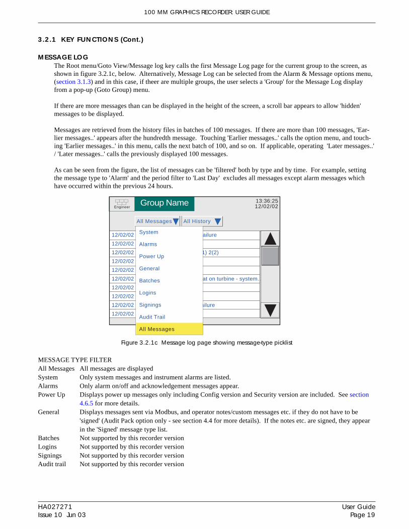
MESSAGE LOG The Root menu/Goto View/Message log key calls the first Message Log page for the current group to the screen, asshown in figure 3.2.1c, below. Alternatively, Message Log can be selected from the Alarm & Message options menu,(section 3.1.3) and in this case, if theer are multiple groups, the user selects a 'Group' for the Message Log displayfrom a pop-up (Goto Group) menu.
If there are more messages than can be displayed in the height of the screen, a scroll bar appears to allow 'hidden'messages to be displayed.
Messages are retrieved from the history files in batches of 100 messages. If there are more than 100 messages, 'Ear-lier messages..' appears after the hundredth message. Touching 'Earlier messages..' calls the option menu, and touch-ing 'Earlier messages..' in this menu, calls the next batch of 100, and so on. If applicable, operating 'Later messages..'/ 'Later messages..' calls the previously displayed 100 messages.
As can be seen from the figure, the list of messages can be 'filtered' both by type and by time. For example, settingthe message type to 'Alarm' and the period filter to 'Last Day' excludes all messages except alarm messages whichhave occurred within the previous 24 hours.
Figure 3.2.1c Message log page showing message-type picklist
MESSAGE TYPE FILTERAll Messages All messages are displayedSystem Only system messages and instrument alarms are listed.Alarms Only alarm on/off and acknowledgement messages appear.Power Up Displays power up messages only including Config version and Security version are included. See section
4.6.5 for more details.General Displays messages sent via Modbus, and operator notes/custom messages etc. if they do not have to be
'signed' (Audit Pack option only - see section 4.4 for more details). If the notes etc. are signed, they appearin the 'Signed' message type list.
Batches Not supported by this recorder versionLogins Not supported by this recorder versionSignings Not supported by this recorder versionAudit trail Not supported by this recorder version
EngineerGroup Name 13:36:25
12/02/02
All Messages All History
12/02/02 11:19:57 Maths Channel Failure
12/02/02 11:19:57 Power Up
12/02/02 10:55:36 Alarm(s) Ackd 2(1) 2(2)
12/02/02 10:48:14 Alarm(s) off 2(1)
12/02/02 10:39:03 Alarm(s) off 1(1)
12/02/02 10:20:16 Engineer,Overheat on turbine - system..
12/02/02 10:19:57 Alarm(s) on 1(1)
12/02/02 10:10:42 Alarm(s) on 2(1)
12/02/02 09:09:12 Maths Channel failure
12/02/02 11:19:57 Power Up
System
Alarms
Power Up
General
Batches
Logins
Signings
Audit Trail
All Messages

100 MM GRAPHICS RECORDER: USER GUIDE
HA027271Issue 10 Jun 03
User GuidePage 20
3.2.1 KEY FUNCTIONS (Cont.)
PERIOD FILTERThis picklist allows the user to select one of the following to define the period of time that the message list is to en-compass:All History, Last Month (28 days), Last Week, Last 3 Days, Last Day or Last Hour,
OPTION MENUTouching a message (highlights yellow) calls the Option Menu* as shown in figure 3.2.1d, below.
Figure 3.2.1d Message Log options menu
Note See section 3.5 of this manualEnter history Operating the Enter History key causes the recorder to display that page of history which
includes the highlighted message. See section 3.4.1 for details of trend history. When inTrend history mode, operating the Message Log key calls that message log page whichcontains those messages which are nearest the trend history cursor time.
Full details If the highlighted message is wider than the display, the whole message can be displayed byoperating the 'Full Details' key.
Refresh/Earlier messages../Later messages.. 'Refresh' places (at the top of the screen), any messages, which have occurred since theMessage Log page was last entered, or since the last 'Refresh'. If earlier or later messages havebeen selected, then 'Refresh' is replaced by 'Earlier messages..' or 'Later messages..' as appro-priate, and operating the key calls the next or previously displayed group of 100 messages tothe display respectively.
* The option menu can also be called by touching the option key. In this case:a. Enter History calls the current Trend History display, as described in section 3.4.1, andb. Because no message is highlighted, the 'Full Details' key is not enabled,
Notes:1 Selecting 'Enter History' whilst either 'Earlier Messages' or 'Later Messages' is highlighted calls the cur-
rent History page.2 If the Option Menu has 'timed out' leaving a message highlighted, and the option key is operated, then
this is equivalent to reselecting the message.
EngineerGroup Name 13:36:25
12/02/02
All Messages All History
11/02/02 11:19:57 Maths Channel Failure
11/02/02 11:19:57 Power Up
11/02/02 10:55:36 Alarm(s) Ackd 2(1) 2(2)
11/02/02 10:48:14 Alarm(s) off 2(1)
11/02/02 10:39:03 Alarm(s) off 1(1)
11/02/02 10:20:16 Engineer,Overheat on turbine - system..
11/02/02 10:19:57 Alarm(s) on 1(1)
11/02/02 10:10:42 Alarm(s) on 2(1)
11/02/02 09:09:12 Maths Channel failure
Earlier messages..
Note
Enter History
Full Details
Earlier messages..
Option Menu

100 MM GRAPHICS RECORDER: USER GUIDE
User GuidePage 21
HA027271Issue 10 Jun 03
3.3 FIRST SWITCH-ON
When power is applied the recorder initialises, and once this process is complete, the home page is displayed. It isunlikely that this will contain any useful information because the input channels will not, as yet, have been configuredto suit the type of input signals being applied to them, as described in section 4.
Notes:1. There is no on-off switch associated with the recorder2. Date, time and the message 'Power Up' are printed on the chart each time power is applied to the recorder,
followed by date, time, Config version, Security version - see 'About' (section 4.6.5)3. A red line is drawn across the width of the chart at power up.
The recorder has four security levels as followsLogged out Initially, no access to recorder configuration is possible. Only Archive, Security/Login and the System
'About' functions can be accessed - via the root menu. Limited or full access can be permitted from'Engineer' level.
Operator No access to recorder configuration is possible until access permissions have been set up. Section 4.4.1,describes how limited or full access can be permitted by an operator with 'Engineer' level access.
Engineer Accessed initially, by entering '10' as the password (section 3.3.1 below). Full access to all recorderfunctions is available. Section 4.1.1 describes how the Engineer password can be edited and an Opera-tor level password edited, if required. The section also describes how access permission to some or allof the recorder functions can be granted, or not, to individual user names and default security levels(except service).
Service Full access to all recorder functions and to areas of recorder memory for diagnostic purposes. For useonly by Service Engineers.
100 MM GRAPHICS RECORDER: USER GUIDE
HA027271Issue 10 Jun 03
User GuidePage 22
Login
Select the required access level and enter the password ifrequired.
User Logged out
Cancel
Operator
Engineer
Service
Logged out
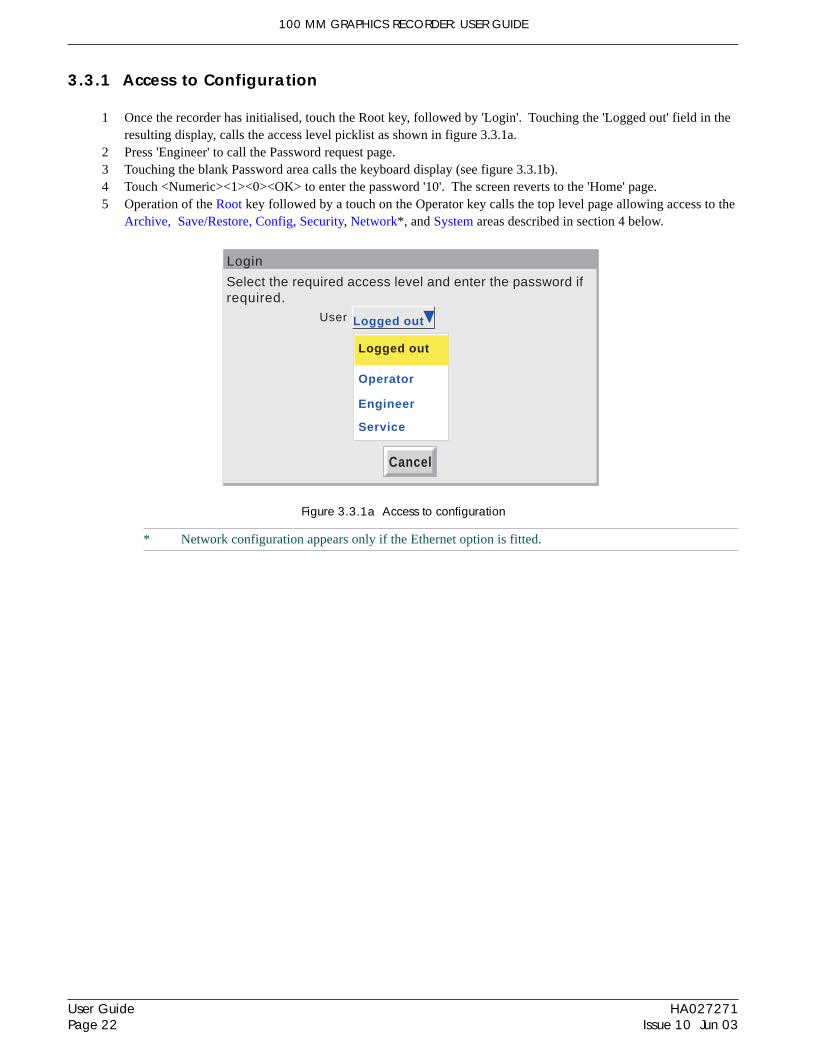
3.3.1 Access to Configuration
1 Once the recorder has initialised, touch the Root key, followed by 'Login'. Touching the 'Logged out' field in theresulting display, calls the access level picklist as shown in figure 3.3.1a.
2 Press 'Engineer' to call the Password request page.3 Touching the blank Password area calls the keyboard display (see figure 3.3.1b).4 Touch <Numeric><1><0><OK> to enter the password '10'. The screen reverts to the 'Home' page.5 Operation of the Root key followed by a touch on the Operator key calls the top level page allowing access to the
Archive, Save/Restore, Config, Security, Network*, and System areas described in section 4 below.
Figure 3.3.1a Access to configuration
* Network configuration appears only if the Ethernet option is fitted.

100 MM GRAPHICS RECORDER: USER GUIDE
User GuidePage 23
HA027271Issue 10 Jun 03
3.3.1 ACCESS TO CONFIGURATION (Cont.)
TEXT STRING ENTRYThe keyboard which appears when the password area is touched is the same as that which appears when any non-numeric text string entry is required (e.g. channel descriptor). Figures 3.3.1b and 3.3.1c below are an attempt, withinthe limitations of the illustrating process, to depict the available keyboards and thus the available character set. Actualentry of the text string is by touching the relevant key. For items which require only a numeric entry (e.g. channelrange) the numeric keyboard appears.
When editing existing text strings, the existing text string appears highlighted, and will be replaced in its entirety bythe first character entered. To avoid this, the left arrow key can be touched to 'unhighlight' it.
Immediately below the keyboard are six keys with the functions listed below. When active, the background colourchanges to yellow for as long as the key is active.
Shift* Once the shift key has been pressed, the next-entered letter appears as a capital; subsequent letters are inlower case.
Caps* When pressed, all subsequent letters appear as capital letters until the Caps key is operated againBSpc This backspace key deletes character to the left of the cursor.Ovr If selected, the next-entered character replaces (overwrites) the existing character to the right of the cursor
position. If not selected, the next-entered character in inserted into the existing text string at the cursor posi-tion.
Ok Used to save the new text string and to return to the page from which the keyboard was called.Cancel Causes a return to the page from which the keyboard was called without saving the new string.
*Note: The character on each display key is always a capital letter, whether or not the actual character beingentered is in capitals or lower case.
SymbolsNumericAlphabet 2
**
Alphabet
Shift Caps BSpc Ovr Ok Cancel
Tabs showactive keyboard
Shift keyCaps Lock
BackspaceOverprint
Text string(all * for password)
Q W E R T Y U I O P
A S D F G H J K L
Z X C V B N M \ .
Cursor keys
Figure 3.3.1b Alphabet 1 keyboard

100 MM GRAPHICS RECORDER: USER GUIDE
HA027271Issue 10 Jun 03
User GuidePage 24
The 'E' key is used whenentering exponents
3.3.1 ACCESS TO CONFIGURATION (Cont.)
TEXT STRING ENTRY (Cont.)
Figure 3.3.1c Alternative keyboards
SymbolsNumeric
Text String
Alphabet
Shift Caps BSpce Ok Cancel
Alphabet 2
Ovr
SymbolsNumeric
Text String
Alphabet
Shift Caps BSpce Ok Cancel
Alphabet 2
Ovr
Numeric
Text String
Alphabet
Shift Caps BSpce Ok Cancel
Alphabet 2
Ovr
Symbols
a
β Γ δα
τ φ ΩΣθ µ πηε
! " $ ^ & * ( )
- _ + = [ ] : ;
@ ' ~ # > , . ? /
| ' 3
<
%
2
7 8 9
4 5 6
1 2 3
0 . ,E
100 MM GRAPHICS RECORDER: USER GUIDE
User GuidePage 25
HA027271Issue 10 Jun 03
3.4 DISPLAY MODES
The display modes described below allow process values (input channels, totalisers etc. - known collectively aspoints) for the current group to be displayed as vertical or horizontal 'chart' traces (Trend modes), as bargraphs (verti-cal or horizontal) or as numeric values. The display mode associated with the home page is Group 1, Vertical Trendwhen dispatched, but any of the other display modes can be selected as the home page in Configuration/Views - sec-tion 4.3.4. The current display mode can be changed using the Root menu\Goto View key. The Home key returns theuser to the Home page from anywhere in the Operator or Configuration pages in the recorder.
3.4.1 Vertical Trend display
This (default) display (figure 3.4.1b) shows each point in the display group as though it were being traced on a whitechart. (It is possible to display on a black 'chart' instead, by selecting Dark Trend Background in Configuration/Views). In either case, some thought should be given to trace colours selected in channel configuration. When se-lected, dark background applies both to vertical and horizontal trend display modes for both Groups.
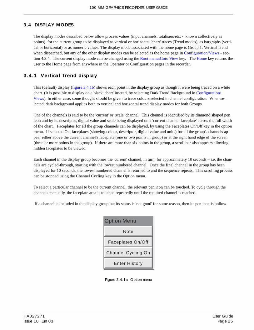
One of the channels is said to be the 'current' or 'scale' channel. This channel is identified by its diamond shaped penicon and by its descriptor, digital value and scale being displayed on a 'current-channel faceplate' across the full widthof the chart. Faceplates for all the group channels can be displayed, by using the Faceplates On/Off key in the optionmenu. If selected On, faceplates (showing colour, descriptor, digital value and units) for all the group's channels ap-pear either above the current channel's faceplate (one or two points in group) or at the right hand edge of the screen(three or more points in the group). If there are more than six points in the group, a scroll bar also appears allowinghidden faceplates to be viewed.
Each channel in the display group becomes the 'current' channel, in turn, for approximately 10 seconds – i.e. the chan-nels are cycled-through, starting with the lowest numbered channel. Once the final channel in the group has beendisplayed for 10 seconds, the lowest numbered channel is returned to and the sequence repeats. This scrolling processcan be stopped using the Channel Cycling key in the Option menu.
To select a particular channel to be the current channel, the relevant pen icon can be touched. To cycle through thechannels manually, the faceplate area is touched repeatedly until the required channel is reached.
If a channel is included in the display group but its status is 'not good' for some reason, then its pen icon is hollow.
Figure 3.4.1a Option menu
Enter History
Channel Cycling On
Faceplates On/Off
Note
Option Menu

100 MM GRAPHICS RECORDER: USER GUIDE
HA027271Issue 10 Jun 03
User GuidePage 26
3.4.1 VERTICAL TREND DISPLAY (Cont.)
TIME CHANGE RECORDSFor vertical trend mode only, a line is drawn across the width of the chart whenever a time discontinuity in the recordoccurs. These lines are volatile in real-time i.e. they disappear if the display mode is changed, or if a configurationpage is called etc.Red line A red line is drawn on the trend history chart at power up.Blue line A blue line indicates that recording has been disable/enabled in Group Configuration (section 4.3.2), or
by a recording job (section 4.7.9).Green line A green line appears if there has been a time change as a result of a clock job (section 4.7.6), an SNTP
synchronisation or by the operator physically changing the recorder time.
Note: Changes from standard time to daylight saving time and back again are not 'green lined' in this way
TREND HISTORYTrend history, allows the user to view the history of the display group. The maximum amount that can be recalleddepends on a number of factors, including how many points are configured, how rapidly the traces are changing andso on. At a recording rate of 20mm/hour (see group configuration - section 4.3.2), with all channels configured, aminimum of 30 day's worth of traces is available for viewing, provided that the group contents are not re-configuredduring this period (in which case, the history starts at the end of the re-configuration). The amount of trace visible onthe screen depends on the recording rate - the higher the rate, the less trace is visible at any one time.
Notes1 Trend history is not available for groups with 'Recording Enable' disabled (Group configuration - section
4.3.2).2 Channel cycling is inhibited in Trend History Mode. To increment the current channel, touch the
faceplate.3 Group faceplates are not displayed in History Mode.4. With A/B switching selected, traces are displayed with the 'A' or 'B' span/zone, colour settings etc. ob-
taining at the cursor time. See sections 4.3.2, 4.3.3 and 4.7 for more details of A/B switching.
To enter Trend History, the Root Menu Options key can be used (as shown in figure 3.4.1), or the trace area of thescreen can be continuously touched until the screen blanks prior to re-drawing. A 'Preparing History, please wait' mes-sage appears whilst the re-drawing calculation is taking place. Although tracing stops whilst trend history mode isactive, no data is lost - Process Variable values are still saved in the recorder memory and alarms are still scanned-forand any associated action taken.
The History display is similar to the real-time trend display, with the addition of a slider control and up and downkeys for selecting that part of trend history which is to be displayed. The controls are used as follows:1 Touching the up/down key causes the record to move an incremental amount.2 Holding the up/down key continuously, causes continuous movement.3 Touching the bar above or below the slider causes a page-height shift.4 Touching and dragging the slider, whilst observing the time/date display, allows the user to select the section of
history exactly.
On first entry to the History mode, the channel value and the time and date shown in the faceplate are those at the topedge of the chart. Touching the screen causes a cursor to appear at point of screen contact. This cursor can betouched and dragged up and down the screen to provide a reference point on the current trace. The displayed valuedate and time refer to the cursor intersection with the current channel. To return to real-time trending, the Options keyin the root menu is operated, followed by 'Exit History'.

100 MM GRAPHICS RECORDER: USER GUIDE
User GuidePage 27
HA027271Issue 10 Jun 03
3.4 DISPLAY MODES (Cont.)
Figure 3.4.1b Typical Vertical Trend display (faceplates enabled) and trend history mode display
Move sliderto requireddate/time
EngineerGroup Name 13:39:12
06/12/0199%
Channel 1 65.55 C
100.000.0000
06/12/01 13:21:02 Alarm(s) off 2 (1)
13:17:4206/12/01
13:31:0206/12/01
13:29:38 06/12/01
Pressarrow keys
to moveminimumamount
Cursor
Realtime/date
Trend history mode
Press bar tomove onepageful
Cursortime/date
Entry to trend mode from Homekey or by cycling screens.
EngineerGroup Name 13:39:12
06/12/0199%
Channel 1 61.59 C
100.000.0000
06/12/01 13:21:02 Alarm(s) off 2 (1)
13:17:4206/12/01
13:31:0206/12/01
06/12/01 13:19:04 Alarm(s) on 2 (1)
Option Menu
Exit History
Note
61.59 C
41.35 C
Channel 1
Channel 2
Channel 3
Channel 4
Channel 5
Channel 6
68.82 C
OFF C
56.57 C
15.66 C
Groupfaceplates
1 or 2 points -faceplatesappear abovecurrent channelfaceplate.
For more than 6points, a scrollbar appears
Current channelfaceplate; Touch/release to incre-ment channel
Touch pen icon toselect that channel
Enter His tory
Channel Cycling On
Faceplates On/Of f
Note
Opt ion Menu
Preparing History, please wait
06/12/01 13:19:04 Alarm(s) on 2 (1)Options
Goto Group
Operator
Login
Goto View
Home
File
Root menuValue at cursor
time/date
Options
Goto Group
Operator
Login
Goto View
Home
File
Root menu

100 MM GRAPHICS RECORDER: USER GUIDE
HA027271Issue 10 Jun 03
User GuidePage 28
3.4 DISPLAY MODES (Cont.)
3.4.2 Horizontal Trend display
This display (figure 3.4.2a) is similar to the Vertical Trend display described above, except that the traces are pro-duced horizontally rather than vertically.
Group Name 12:03:2721/02/01
99%
Channel 1 21.2613 C
0.000
35.00
Engineer
12:00:5221/02/01
12:02:1221/02/01
21/02/01 12:02:20 Alarm(s) off 2 (1)
Faceplates for currentchannel.Touch either faceplate toincrement channel(or touch pen to selectchannel). Bargraph
Current pen icon
Non-currentpen icon
If this arrow is displayed, thentouching the message bar displaysprevious messages
Latest message
Time atadjacentgridline
Message bar
Figure 3.4.2a Horizontal trend display mode
One of the channels is said to be the 'current' or 'scale' channel. This channel is identified by its pen icon being dia-mond shaped rather than triangular as for non-current channels. If a channel is included in the display group but itsstatus is 'not good' for some reason, then its pen icon is hollow. Each channel in the display group becomes the 'cur-rent' channel, in turn, for approximately 10 seconds – i.e. the channels are cycled-through, starting with the lowestnumbered channel. Once the final channel in the group has been displayed for 10 seconds, the lowest numbered chan-nel is returned to and the sequence repeats. This scrolling process can be stopped using the Channel Cycling key inthe Option menu.
As well as the normal faceplate above the 'chart', showing the current channel's descriptor and its digital value, abargraph representation of the current channel's value together with a scale showing the low and high range values forthe channel appears to the right of the chart. Touching the faceplate or the bargraph* causes the current channelnumber to increment. To select a particular channel to be the current channel, the relevant pen icon can be touched. Ineither case, the bargraph and the background colour of the channel descriptor takes the colour of the current channel.
Time and date are printed on the 'chart' immediately to the right of alternate vertical grid lines, and it is these gridlines to which the printed time relates.
There is no horizontal trace Trend History function - touching the 'chart' for a few seconds (or using the Root menuOptions key, then 'Enter History') calls the vertical trend history page described in section 3.4.1, above.
*Note: For 'zoned' points (section 4.3.3), the bargraph must be touched within the scale area to increment thechannel.
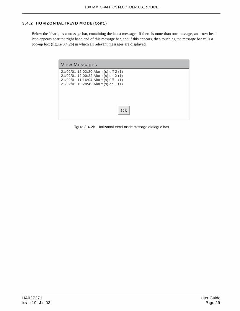
100 MM GRAPHICS RECORDER: USER GUIDE
User GuidePage 29
HA027271Issue 10 Jun 03
3.4.2 HORIZONTAL TREND MODE (Cont.)
Below the 'chart', is a message bar, containing the latest message. If there is more than one message, an arrow headicon appears near the right hand end of this message bar, and if this appears, then touching the message bar calls apop-up box (figure 3.4.2b) in which all relevant messages are displayed.
Figure 3.4.2b Horizontal trend mode message dialogue box
Ok
21/02/01 12:02:20 Alarm(s) off 2 (1)21/02/01 12:00:22 Alarm(s) on 2 (1)21/02/01 11:16:04 Alarm(s) 0ff 1 (1)21/02/01 10:28:49 Alarm(s) on 1 (1)
View Messages
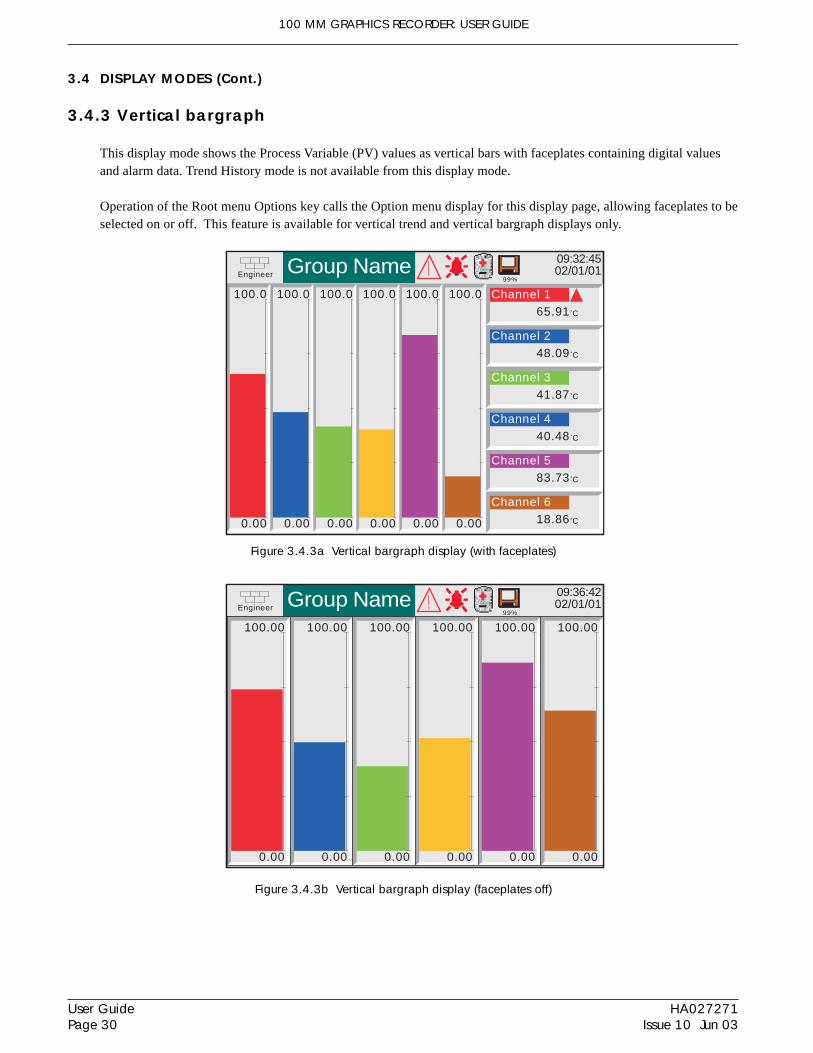
100 MM GRAPHICS RECORDER: USER GUIDE
HA027271Issue 10 Jun 03
User GuidePage 30
3.4 DISPLAY MODES (Cont.)
3.4.3 Vertical bargraph
This display mode shows the Process Variable (PV) values as vertical bars with faceplates containing digital valuesand alarm data. Trend History mode is not available from this display mode.
Operation of the Root menu Options key calls the Option menu display for this display page, allowing faceplates to beselected on or off. This feature is available for vertical trend and vertical bargraph displays only.
Figure 3.4.3b Vertical bargraph display (faceplates off)
Figure 3.4.3a Vertical bargraph display (with faceplates)
Engineer Group Name 09:36:4202/01/01
99%
100.00
0.00
100.00
0.00
100.00
0.00
100.00
0.00
100.00
0.00
100.00
0.00
Engineer Group Name 09:32:4502/01/01
99%
100.0
0.00
100.0
0.00
100.0
0.00
100.0
0.00
100.0
0.00
100.0
0.00
Channel 165.91 C
Channel 248.09 C
Channel 341.87 C
Channel 440.48 C
Channel 583.73 C
Channel 618.86 C

100 MM GRAPHICS RECORDER: USER GUIDE
User GuidePage 31
HA027271Issue 10 Jun 03
3.4.4 Horizontal bargraph
This display mode shows the Process Variable (PV) values as horizontal bars with digital values and alarm data dis-played, as shown in figure 3.4.4. Trend History mode is not available from this display mode.
Engineer Group Name 10:39:3802/01/01
100.000.00
14.59 C
100.000.00
36.02 C
100.000.00
38.37 C
100.000.00
69.90 C
100.000.00
32.04 C
100.000.00
88.27 C
99%
Figure 3.4.4 Horizontal bargraph display

100 MM GRAPHICS RECORDER: USER GUIDE
HA027271Issue 10 Jun 03
User GuidePage 32
3.4 DISPLAY MODES (Cont.)
3.4.5 Numeric
Numeric display mode shows the Process Variable (PV) values as digital values. The format (which is automaticallyselected) is based on the number of channels in the display group. Figures 3.4.5a and 3.4.5b, show typical examplesof the one column (up to four channels) and two column versions (five or six channels) of this display mode, respec-tively. Within each version, the process variable display areas expand or contract to fill the screen. Trend Historymode is not available from this display mode..
Figure 3.4.5a Numeric display mode (1 to 4 channels)
Figure 3.4.5b Numeric display mode (5 or 6 channels)
Engineer Group Name 11:19:3002/01/01
99%
Channel 1
12.21 C
Channel 2
23.32 C
Channel 3
34.43 C
Channel 4
45.54 C
Engineer Group Name 11:00:2402/01/01
99%
Channel 1
12.34 C
Channel 2
23.45 C
Channel 3
34.56 C
Channel 4
45.67 C
Channel 5
56.78 C
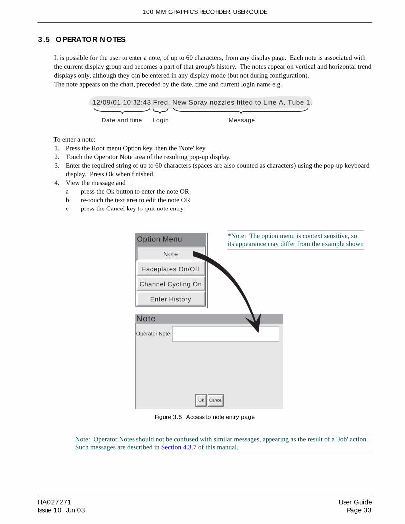
100 MM GRAPHICS RECORDER: USER GUIDE
User GuidePage 33
HA027271Issue 10 Jun 03
3.5 OPERATOR NOTES
It is possible for the user to enter a note, of up to 60 characters, from any display page. Each note is associated withthe current display group and becomes a part of that group's history. The notes appear on vertical and horizontal trenddisplays only, although they can be entered in any display mode (but not during configuration).The note appears on the chart, preceded by the date, time and current login name e.g.
Operator Note
Note
Ok Cancel
Enter History
Channel Cycling On
Faceplates On/Off
Note
Option Menu
Date and time MessageLogin
12/09/01 10:32:43 Fred, New Spray nozzles fitted to Line A, Tube 1.
To enter a note:1. Press the Root menu Option key, then the 'Note' key2. Touch the Operator Note area of the resulting pop-up display.3. Enter the required string of up to 60 characters (spaces are also counted as characters) using the pop-up keyboard
display. Press Ok when finished.4. View the message and
a press the Ok button to enter the note ORb re-touch the text area to edit the note ORc press the Cancel key to quit note entry.
*Note: The option menu is context sensitive, soits appearance may differ from the example shown
Figure 3.5 Access to note entry page
Note: Operator Notes should not be confused with similar messages, appearing as the result of a 'Job' action.Such messages are described in Section 4.3.7 of this manual.

100 MM GRAPHICS RECORDER: USER GUIDE
HA027271Issue 10 Jun 03
User GuidePage 34
4 SETTING UP THE RECORDER
As described in the 'Access to Configuration' (section 3.3.1) above, the setting-up of the recorder is divided into thefollowing areas:Archive Section 4.1 - Allows manual archiving of data to disk or (if the Ethernet option is fitted) to a remote
host (FTP transfer).Save/restore Section 4.2 - Allows new configurations to be created and saved, and saved configurations to be 're-
stored'.Config Section 4.3 - This is the major channel/alarm/option etc. area of configuration.Security Section 4.4 - Allows passwords to be entered and edited and allows the Engineer-level password
holder to enable/disable areas of configuration to Operator-level password holders. New users can beadded, with their own user names, passwords and access level permissions.
Network Section 4.5 - This area sets up the IP / mac address/host names etc. used in FTP transfer, RemoteViewer and SNTP applications (if the Ethernet option is fitted).
System Section 4.6 - Allows:Time and date functions to be set and edited (including daylight saving start and finish dates, timezones etc.)Display language to be chosenOption key codes to be enteredInputs to be adjusted.System contains an 'About' screen describing the software/hardware status of the recorder.
Section 4.7 describes the various job categories available to the user
Note: In all the following descriptions, if a change is made to a menu item, then the item text changes fromblack to red, until it is 'saved'.

100 MM GRAPHICS RECORDER: USER GUIDE
User GuidePage 35
HA027271Issue 10 Jun 03
4.1 ARCHIVE
4.1.1 Archive to disk
This allows the user to initiate data transfer, to a mass storage medium such as a floppy disk, for all groups with 'Ar-chive to Media' enabled (Group configuration - section 4.3.2), by touching the relevant archive period key (e.g. LastDay').
Archiving starts as soon as the selection is made, and cannot be stopped until completed, unless the Cancel Archivekey is operated, in which case the archive will be stopped after a confirmatory message has been responded to. TheCancel key is active only if 'Archiving Control' is enabled in Security/Access (section 4.4 of this manual). If archiv-ing is enabled for more than one group, a warning message appears.
Selection of 'Bring Archive Up To Date' causes the recorder to select whichever of the Last Hour/Last Day etc. cat-egories is appropriate to bring the archive up to date. Figure 4.4.1 shows the archive to disk menu.
Figure 4.1.1 Disk archive strategy configuration
If the disk becomes full before archiving is complete, archiving pauses and a pop-up request appears, asking for thedisk to be replaced. If this request is not responded-to within 10 minutes of its appearance, archiving is aborted,
Unattended archiving can be paused by the user (e.g. to change disks without losing data) by operating the 'SuspendArchiving' / 'Resume Archiving' button. Any archiving in progress is allowed to complete before the 'Suspend Archiv-ing' request takes effect. Transfer activity is indicated in the 'Archive transfer' window. Should the disk become full,the user will be prompted to replace it with a different one.
Below the selection buttons are a number of status windows relating to the mass storage medium.
If automatic archiving is active (section 4.3.5), then this and the manual archive will operate on a first come-firstserved basis. Some files will be saved twice in such a circumstance, the later archive's files overwriting any earlierarchive's files which have the same name.
Last Archive
Archive Last Hour
Archive Transfer
Media Size Bytes
Free Space Bytes
Archive Last Day
Archive Last Week
Archive Last Month
Archive All
Suspend Archiving
Cancel Archive
Disk
Remote
Archive SystemConfig Security NetworkSave/R..
Section 4.1.2
Bring Archive Up To Date

100 MM GRAPHICS RECORDER: USER GUIDE
HA027271Issue 10 Jun 03
User GuidePage 36
4.1.2 Remote archiving (FTP transfer)
This allows archiving of recorder files, for all groups with 'Archive via FTP' enabled, to a remote computer, connected(using the RJ45 telephone type connector at the rear of the recorder) either directly, or via a network . 'Archive viaFTP' is enabled/disabled as part of (Group configuration - section 4.3.2)
In order to carry out a successful transfer, details of the remote host must be entered in the Archive section of the'Config' menu (section 4.3.5).
Note: An FTP server must be running on the remote host.
Figure 4.1.2 shows the archive menu for remote archiving. The Archive last hour/day/week etc. keys allow the user todetermine which files are to be archived. Selection of 'Bring Archive Up To Date' causes the recorder to select which-ever of the Last Hour/Last Day etc. categories is appropriate in order to bring the archive up to date. The 'Last Ar-chive' window shows the time and date of the previous archive. The Archive Transfer window shows archive status as'Active' or 'Inactive'.
Figure 4.1.2 Remote archive strategy configuration
Additionally, a user on a remote PC has full viewing capabilities, can extract recorder files at any time, and can accessthose items of recorder configuration that are associated with the user's login. For successful connection, 'Connectfrom Remote' must be enabled and the 'Remote user name' and 'Remote password' must be defined in one of the ac-counts (all in the Security access menu (section 4.4.1)).
Notes:1. In order to view history files when accessing the instrument remotely, the recorder's address, the 'Remote
user name' and the 'Remote password' must be supplied to an FTP client such as PC Review orMicrosoft® Internet Explorer.
2. When accessing files using Microsoft® Internet Explorer, the address (URL) field can be in one of twoforms:a ftp://<instrument IP address>. This allows the user to log in as the anonymous user (if the instru-
ment has any account with 'Remote user name' set to 'Anonymous' and a blank password).b ftp://<user name>:<password>@<instrument IP address> to log in as a specific user.
3. For IE5 users only: Microsoft® Internet Explorer displays, by default, history files only. To exit thehistory folder, either uncheck the Tools/Internet Options/Advanced/Browsing/"Enable folder view forFTP sites" option, or check the Tools/Internet Options/Advanced/Browsing/"Use Web based FTP" option.
Last Archive
Archive Last Hour
Archive Transfer
Archive Last Day
Archive Last Week
Archive Last Month
Archive All
Cancel Archive
Disk
Remote
Archive SystemConfig Security NetworkSave/R..
Section 4.1.1
Bring Archive Up To Date

100 MM GRAPHICS RECORDER: USER GUIDE
User GuidePage 37
HA027271Issue 10 Jun 03
4.2 SAVE / RESTORE
As shown in figure 4.2a, touching the Save/Restore key calls the picklist: Save, Restore, New, Text, Import/Exportuser Linearisation.
Figure 4.2a Save/Restore menu
Where a file name is required, then, if the displayed file name is suitable, operation of the 'Save', 'Restore', 'Import' or'Export' key will initiate the action. If, instead, a file name has to be entered, this is carried out as follows:
Touching the file name window causes a pop-up menu to appear, giving a list of 'Volumes' in the Flash memory or onthe floppy disk (if inserted). Figure 4.2b shows an imaginary Volume contents list, displayed by touching the name'user', then operating the 'open folder' key. (See section 5, below for more details). Once the correct folder is open,either select an existing file, or enter a new file name, by touching the FileName window and entering the name usingthe pop-up keyboard(s) as described in section 3.3.1 above. Operation of the Save or Restore key initiates the action.
Figure 4.2b Typical volume contents page
Save
Restore
New
Text
File Name
Save
File Name
Network Data
Screen Data
Security Data
Configuration Data
Restore
New/Default
Network Data
Screen Data
Security Data
Configuration Data
File Name
Save As Text
Import User Linearisation
Export User Linearisation
Save for pre Version 1.8
Archive SystemSave/R.. Config Security Network
User LinearisationFile Name
1) UserLin1
userlin
Import Export
Hide\user\
TypeNamecal\
config\
lib\
Folder
Folder
Folder
SaveFileName: Filter1b
sdb\ Folder
Date
03/06/00 12:35:08
01/05/00 10:27:13
05/07/00 10:23:14
11/05/00 14:01:08
Filter1a Config 05/07/00 10:22:23
Bytes
4445
Cancel

100 MM GRAPHICS RECORDER: USER GUIDE
HA027271Issue 10 Jun 03
User GuidePage 38
4.2.1 Save
Touching this item allows the current configuration to be saved in the recorder's memory. Files saved in this way arenot in a 'readable' format and are used only for archive /security purposes or for transfer to another, similar, recorder.
SAVE FOR PRE VERSION 1.8 Checking this box, prior to saving a configuration, means that the configuration can successfully be loaded (Restored)into other recorders running software versions prior to 1.8. If the box is left unchecked, then Saved configurationscan be Restored only to recorders running software versions 1.8 or higher. The message 'Unsupported File' appears ifan attempt is made to save an 'Unchecked' configuration into a pre version 1.8 recorder. See Section 4.6.5 (About) fordetails of how to determine software version.
4.2.2 Restore
Touching this item allows the user to select or type-in a previously saved configuration file name, which will then beused as the current configuration. Touching the 'Restore' key completes the operation. Tick boxes allow one or moreof Configuration, Security, Network or Screen data to be chosen to be restored.
Notes1 Screen data relates to faceplate status for vertical trend and vertical bargraph display modes.2. if archiving is in progress when a 'Restore' is requested, the Restore operation will be delayed until the
archive is complete (maybe several minutes). If required, the 'Cancel Archive' key can be used to speedup the restore process, at the cost of losing the archive data.
4.2.3 New
Touching this item causes the factory entered default configuration to be loaded for use, or for editing. Operation ofthe New/Default key completes the operation. Tick boxes allow one or more of Configuration, Security, Network orScreen data to be chosen to be restored. (Screen data relates to faceplate status for vertical trend and vertical bargraphdisplay modes.)
4.2.4 Text
This is identical to the 'Save' function described above, but the configuration is saved in ASCII format, and can betransferred to a computer and read, printed etc. as required. It is not possible, using this means, to modify the con-figuration and then re-load it.

100 MM GRAPHICS RECORDER: USER GUIDE
User GuidePage 39
HA027271Issue 10 Jun 03
4.2.5 Import User Linearisation
The Import Linearisation feature allows linearisation tables to be imported either via the floppy disk, or if the RemoteViewer option is fitted,directly from the host PC.
Touching the User Linearisation field allows the user to select which of 'UserLin1' to 'UserLin4' is to contain the im-ported file.
Touching the File Name field, calls a popup menu similar to that shown in figure 4.2b. This allows the user to selectthe table to be imported.
The file must be comma separated ASCII as follows:n,X1,Y1X2.Y2X3,Y3 . .Xn,Ynwhere 'n' is the total number of XY pairs in the table, and or each pair, X is the input value, and Y is the linearisedvalue corresponding to X.
See section 4.3.8 for full details.
Note: Imported linearisation tables will not become effective until after the next configuration 'Apply'operation
4.2.6 Export User Linearisation
Similar to 'Import user Linearisation, above, the Export Linearisation feature allows linearisation tables created in therecorder to be exported either via the floppy disk, or if the Remote Viewer option is fitted,directly to the host PC.
See section 4.3.8 for full details.
Note: If an exported linearisation table is to be used in a recorder with software version prior to version 2.2, itmust be exported in Numeric format (i.e. not in Scientific format).

100 MM GRAPHICS RECORDER: USER GUIDE
HA027271Issue 10 Jun 03
User GuidePage 40
4.3 CONFIGURATION
Touching this key calls the top level configuration pick list: Instrument, Groups, Channels, Views, Archive, Events,Messages, etc. as shown in the overview figure (figure 4.3).
When making changes to the configuration the name of each changed parameter is displayed in red (instead of thenormal black) until the 'Apply/Discard' key has been operated. For example, in channel configuration, if a thermocou-ple were to be changed from Type J to Type K, 'Lin Type' would appear in red, until the Apply key was operated.
Should an attempt be made to leave configuration with unsaved changes, a warning message appears, allowing theuser to apply the changes, to discard the changes or to return to configuration (Cancel).
Config
Discard Cancel
Data has been modified
Apply
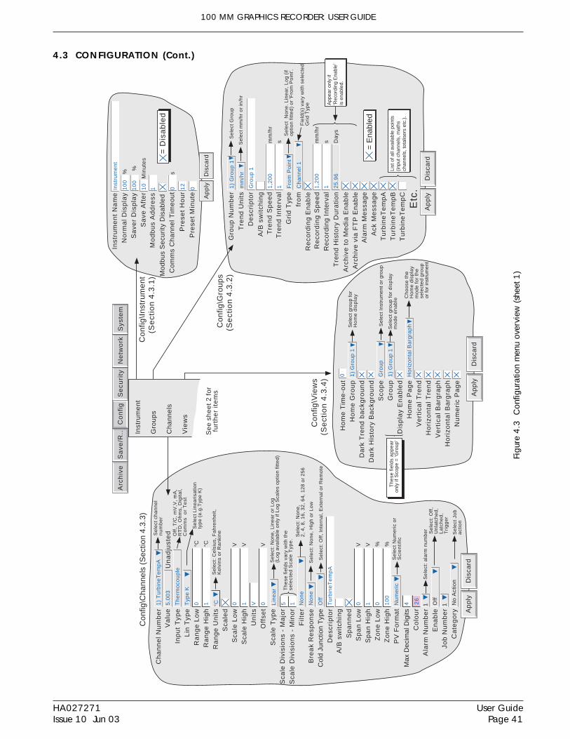
100 MM GRAPHICS RECORDER: USER GUIDE
User GuidePage 41
HA027271Issue 10 Jun 03
Figu
re 4
.3 C
onfig
urat
ion
men
u ov
ervi
ew (s
heet
1)
4.3 CONFIGURATION (Cont.)
Arc
hiv
eS
yste
mS
ave
/R..
Co
nfi
gS
ecu
rity
Ne
two
rk
Se
e s
he
et
2 f
or
furt
he
r it
em
s
Ap
ply
Dis
card
Ch
an
ne
l N
um
be
r1
) T
urb
ine
Te
mp
AS
ele
ct c
ha
nn
el
nu
mb
er
Inp
ut
Typ
eT
he
rmo
cou
ple
Se
lect
Lin
ea
risa
tion
typ
e (
e.g
.Typ
e K
)
Lin
Typ
eT
ype
K
Off
, T
/C,
mV
,V,
mA
,R
TD
, O
hm
s, D
igita
l,C
om
ms
or
Te
st
Ra
ng
e L
ow
0C
Ra
ng
e H
igh
1C
Ra
ng
e U
nit
sC
Sca
led
Sca
le L
ow
0V
Sca
le H
igh
1V
Se
lect
: C
els
ius,
Fa
hre
nh
eit,
Ke
lvin
s o
r R
an
kin
e
Un
its
V
Off
set
0V
Filt
er
No
ne
Se
lect
: N
on
e,
2,
4,
8,
16
, 3
2,
64
, 1
28
or
25
6
Bre
ak
Re
spo
nse
No
ne
Se
lect
: a
larm
nu
mb
er
Col
d Ju
nctio
n T
ype
Off
De
scri
pto
rT
urb
ine
Te
mp
A
Se
lect
: O
ff,
Inte
rna
l, E
xte
rna
l or
Re
mo
te
Sp
an
ne
dS
pa
n L
ow
0V
Sp
an
Hig
h1
V
Zo
ne
Lo
w0
%
Zo
ne
Hig
h1
00
%
Max
Dec
imal
Dig
its4
Co
lou
rA
larm
Nu
mb
er
1
En
ab
leO
ff
Job
Nu
mb
er
1
Ca
teg
ory
No
Act
ion
Se
lect
: O
ff,
Un
latc
he
d,
La
tch
ed
,T
rig
ge
r
Se
lect
Jo
ba
ctio
n
26
Se
lect
: N
on
e,
Hig
h o
r L
ow
Un
ad
just
ed
5.0
03
Va
lue
Ap
ply
Dis
card
Ala
rm M
ess
ag
eA
ck M
ess
ag
eT
urb
ine
Te
mp
AT
urb
ine
Te
mp
BT
urb
ine
Te
mp
C
= E
nabl
ed
Etc
.
Re
cord
ing
Sp
ee
dR
eco
rdin
g I
nte
rva
l11
,20
0m
m/h
r
s
Arc
hiv
e t
o M
ed
ia E
na
ble
Arc
hiv
e v
ia F
TP
En
ab
le
List
of a
ll av
aila
ble
poin
ts(in
put c
hann
els,
mat
hsch
anne
ls, t
otal
iser
s et
c.).
Tre
nd
His
tory
Du
rati
on
25
.96
Da
ys
Se
lect
mm
/hr
or
in/h
rT
ren
d U
nit
sm
m/h
r
De
scri
pto
r
Tre
nd
Sp
ee
dT
ren
d I
nte
rva
l11
,20
0m
m/h
r
s
Gro
up
1
Gro
up
Nu
mb
er
1)
Gro
up
1S
ele
ct G
rou
p
Re
cord
ing
En
ab
le
App
ear
only
if'R
ecor
ding
Ena
ble'
is e
nabl
ed.
Ho
me
Tim
e-o
ut
1)
Gro
up
1S
elec
t gro
up fo
rH
om
e d
isp
lay
Ho
me
Gro
up
Da
rk T
ren
d b
ack
gro
un
dD
ark
His
tory
Ba
ckg
rou
nd
Sco
pe
Gro
up
Dis
pla
y E
na
ble
dH
om
e P
ag
eV
ert
ica
l T
ren
dH
ori
zon
tal
Tre
nd
Ve
rtic
al
Ba
rgra
ph
Nu
me
ric
Pa
ge
Gro
up
Sel
ect I
nstr
umen
t or
grou
p
1)
Gro
up
1S
ele
ct g
rou
p f
or
dis
pla
ym
od
e e
na
ble
Ho
rizo
nta
l Ba
rgra
ph
Ch
oo
se t
he
Ho
me
dis
pla
ym
od
e f
or
the
sele
cte
d g
rou
por
for
inst
rum
ent
Ho
rizo
nta
l B
arg
rap
h
0
Th
ese
fie
lds
ap
pe
ar
only
if S
cope
= 'G
roup
'
Ap
ply
Dis
card
Co
nfig
\Vie
ws
(Se
ctio
n 4
.3.4
)
Inst
rum
en
t N
am
eN
orm
al
Dis
pla
yS
ave
r D
isp
lay
Inst
rum
en
t
Sa
ve A
fte
r
10
0
10
%
%
Min
ute
s
Mo
db
us
Se
curi
ty D
isa
ble
dC
om
ms
Ch
an
ne
l Tim
eo
ut
s
10
0
0
= D
isa
ble
d
Pre
set
Ho
ur
12
Pre
set
Min
ute
0
Ap
ply
Dis
card
Co
nfig
\In
stru
me
nt
(Se
ctio
n 4
.3.1
)
Co
nfig
\Gro
up
s(S
ect
ion
4.3
.2)
Inst
rum
en
t
Gro
up
s
Ch
an
ne
ls
Vie
ws
Con
fig\C
hann
els
(Sec
tion
4.3.
3)
Sca
le T
ype
Sca
le D
ivis
ion
s -
Ma
jor
Sca
le D
ivis
ion
s -
Min
or
Lin
ea
r
5 1
Se
lect
: N
on
e,
Lin
ea
r o
r L
og
(Lo
g a
vaila
ble
on
ly if
Lo
g S
cale
s o
ptio
n f
itte
d)
Th
ese
fie
lds
vary
with
th
ese
lect
ed
Sca
le T
ype
.
PV
Fo
rma
tN
um
eri
cS
ele
ct N
um
eri
c o
rS
cie
nti
fic
Gri
d T
ype
Fro
m P
oin
tS
ele
ct N
on
e.
Lin
ea
r, L
og
(if
op
tion
fitt
ed
) o
r 'F
rom
Po
int'.
fro
mC
ha
nn
el 1
Fie
ld(s
) va
ry w
ith s
ele
cte
dG
rid
Typ
e
A/B
sw
itch
ing
A/B
sw
itch
ing
Mo
db
us
Ad
dre
ss1

100 MM GRAPHICS RECORDER: USER GUIDE
HA027271Issue 10 Jun 03
User GuidePage 42
Figu
re 4
.3 C
onfig
urat
ion
men
u ov
ervi
ew (s
heet
2)
4.3 CONFIGURATION (Cont.)
Use
r Li
near
isat
ion
Des
crip
tor
For
mat
Num
ber
of P
oint
s
X1
Y1
X2
3) U
serL
in3
Num
eric
2 0 0 1
Y2
1
App
lyD
isca
rd
Sel
ect N
umer
ic o
rS
cie
nti
fic
Con
fig\U
ser
Line
aris
atio
ns(S
ect
ion
4.3
.8)
App
lyD
isca
rd
Arc
hiv
e t
o R
em
ote
No
ne
Sel
ect:
Hou
rly,
Dai
ly,
Wee
kly,
Mon
thly
, Aut
omat
ic
Re
mo
te p
ath
Sh
ow
Rem
ote
sett
ings
0.0.
0.0
Pri
ma
ry r
em
ote
ho
st
Pri
ma
ry lo
gin
na
me
an
on
ym
ou
s
Pri
ma
ry p
ass
wo
rd* *
* **
Re
typ
e p
ass
wo
rd* *
* **
0.0.
0.0
Sec
onda
ry r
emot
e ho
stS
eco
nd
ary
log
in n
am
ea
no
ny
mo
us
Se
con
da
ry p
ass
wo
rd* *
* **
Re
typ
e p
ass
wo
rd* *
* **
/ re
co
rde
r /G
rou
p1
Co
mp
ress
ion
Nor
mal
Fla
sh S
ize
2.7
5M
b
Sh
ort
est
Tre
nd
His
tory
Gro
up
1
Sel
ect:
Nor
mal
or
Hig
h
Du
rati
on
8.7
7D
ays
Con
fig\A
rchi
ve(S
ect
ion
4.3
.5)
Re
mo
te
Dis
k
For
pre
viou
s ite
ms
see
sh
ee
t 1
Arc
hiv
eS
yste
mS
ave
/R..
Co
nfi
gS
ecu
rity
Ne
two
rk
Me
ssa
ge
Nu
mb
er
Me
ssa
ge
Re
pla
ce
1
wit
h
Re
pla
ce
2
wit
h
Re
pla
ce
3
wit
h3
so
urc
eR
ep
lace
4
w
ith
4
sou
rce
Re
pla
ce
5
wit
h
App
lyD
isca
rd
Sel
ect:
Sou
rce
Des
crip
tor,
Sou
rce
Val
ue,
Spe
cifie
d D
escr
ipto
r,S
peci
fied
Val
ue o
rB
lank
Re
pla
ce
6
wit
h
1) T
he v
alue
of
The
val
ue o
f 1
=
2 &
3
=
4
Sou
rce
Des
crip
tor
Sou
rce
Val
ue
Tot
alis
er 1
Spe
cifie
d D
escr
ipto
r
Tot
alis
er 1
Spe
cifie
d V
alue
Bla
nk
Bla
nk
Sel
ect:
Cha
nnel
/tot
alis
er e
tc.
who
se d
escr
ipto
r/va
lue
is to
be
inse
rted
Sel
ect M
essa
ge 1
to 1
2fo
r co
nfig
urat
ion
Co
nfi
g\E
ven
ts (
Se
ctio
n 4
.3.6
)
Con
fig\M
essa
ges
(Se
ctio
n 4
.3.7
)
Arc
hive
Eve
nts
Mes
sage
s
Use
r Li
near
isat
ions
Mat
hs
Tot
alis
ers
Cou
nter
s
Tim
ers
Op
tio
ns
Mat
hs..
....
...O
ptio
ns s
ectio
n 3
Tot
alis
ers.
..O
ptio
ns s
ectio
n 4
Cou
nter
s...
. Opt
ions
sec
tion
5T
imer
s...
....
.Opt
ions
sec
tion
6
So
ftw
are
op
tio
ns
Con
fig\O
ptio
ns(S
ect
ion
4.3
.9)
App
lyD
isca
rd
Arc
hiv
e t
o M
ed
ia
On
Me
dia
Fu
l l
Co
mp
ress
ion
No
ne
Me
dia
Siz
e1.
38M
bSel
ect:
Hou
rly,
Dai
ly, W
eekl
y,M
onth
ly o
r A
utom
atic
Ove
rwri
te
Nor
mal
Fla
sh S
ize
2.7
5M
b
Dis
k A
rchi
ve C
apac
ity3
.57
Da
ys
Sh
ort
est
Tre
nd
His
tory
Gr o
up
1
Sel
ect:
Ove
rwri
te o
r S
top
Sel
ect:
Nor
mal
or
Hig
h
Sh
ow
Dis
k se
ttin
gsS
elec
t 'D
isk'
or
'Re
mo
te' s
ett
ing
s
Du
rati
on
7.2
8D
ays
Me
dia
Fu
l l e
ven
t l im
it1
00
%
Fitt
ed
ch
an
ne
ls6
App
lyD
isca
rdA
utoc
onf ig
ure
(cu
rre
ntly
0)
Re
mo
te V
iew
ers
4
File
Tra
nsf
er
Pro
toco
l4
Mo
db
us/
TC
P C
lien
ts2
Me
ssa
ge
s1
2
Re
lay
Bo
ard
s1
Re
lays
on
bo
ard
11
(cu
rre
ntly
0)
To
talis
ers
6
Co
un
ters
Tim
ers
6
Ma
ths
6
Gro
up
s26
Re
mo
te V
iew
er
Le
vel
Fu
ll
Use
r lin
ea
risa
tion
s4
Lo
ga
rith
mic
Sca
les
En
ab
led
Eve
nts
6
Ala
rms
Pe
r2
App
lyD
isca
rd
Sel
ect 1
to 6
Eve
nt
Nu
mb
er
1) E
vent
1
So
urc
e 1
De
scri
pto
rE
vent
1
Sel
ect:
1 o
r 2
Job
Nu
mb
er
1
Ca
teg
ory
No
Act
ion
Sel
ect J
ob C
ateg
ory
Ala
rm o
n G
roup
Sel
ect s
ourc
e 1
On
Gro
up
1) G
roup
1
So
urc
e 2
Poi
nt A
larm
Sel
ect s
ourc
e 2
On
Mat
h 12
Ala
rm2
So
urc
e 1
Se
nse
Op
era
tor
So
urc
e 2
Se
nse
Sou
rce
1
An
d
Not
Sou
rce
2Mak
e su
b-su
b se
lect
ion
(if a
ny)
Sel
ect l
ogic
com
bina
tion:
Onl
y, A
ND
,O
R, N
AN
D, N
OR
, XO
R.
Sel
ect s
ourc
e in
vers
ion
or n
ot
Sel
ect s
ourc
e in
vers
ion
or n
ot
Mak
e so
urce
1 s
ub s
elec
tion
(if a
ny)
Mak
e so
urce
2 s
ub s
elec
tion
(if a
ny)
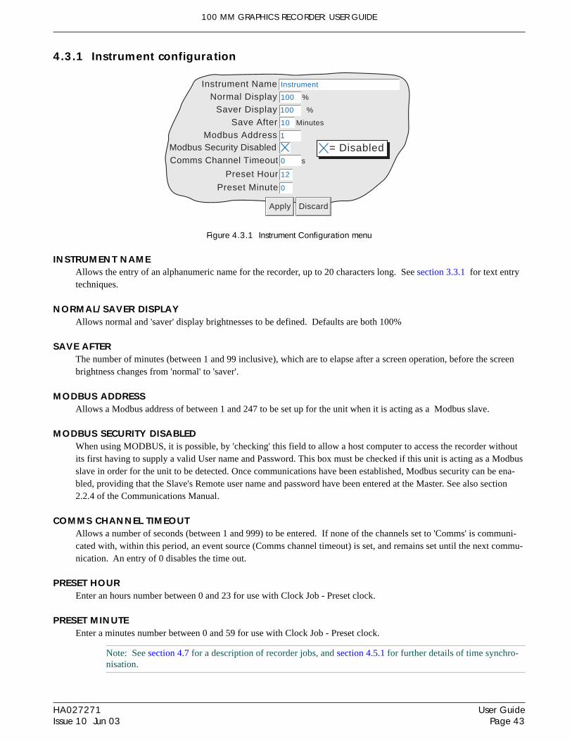
100 MM GRAPHICS RECORDER: USER GUIDE
User GuidePage 43
HA027271Issue 10 Jun 03
4.3.1 Instrument configuration
Figure 4.3.1 Instrument Configuration menu
INSTRUMENT NAMEAllows the entry of an alphanumeric name for the recorder, up to 20 characters long. See section 3.3.1 for text entrytechniques.
NORMAL/SAVER DISPLAYAllows normal and 'saver' display brightnesses to be defined. Defaults are both 100%
SAVE AFTERThe number of minutes (between 1 and 99 inclusive), which are to elapse after a screen operation, before the screenbrightness changes from 'normal' to 'saver'.
MODBUS ADDRESSAllows a Modbus address of between 1 and 247 to be set up for the unit when it is acting as a Modbus slave.
MODBUS SECURITY DISABLEDWhen using MODBUS, it is possible, by 'checking' this field to allow a host computer to access the recorder withoutits first having to supply a valid User name and Password. This box must be checked if this unit is acting as a Modbusslave in order for the unit to be detected. Once communications have been established, Modbus security can be ena-bled, providing that the Slave's Remote user name and password have been entered at the Master. See also section2.2.4 of the Communications Manual.
COMMS CHANNEL TIMEOUTAllows a number of seconds (between 1 and 999) to be entered. If none of the channels set to 'Comms' is communi-cated with, within this period, an event source (Comms channel timeout) is set, and remains set until the next commu-nication. An entry of 0 disables the time out.
PRESET HOUREnter an hours number between 0 and 23 for use with Clock Job - Preset clock.
PRESET MINUTEEnter a minutes number between 0 and 59 for use with Clock Job - Preset clock.
Note: See section 4.7 for a description of recorder jobs, and section 4.5.1 for further details of time synchro-nisation.
Instrument NameNormal Display
Saver Display
Instrument
Save After
100
10
%
%
Minutes
Modbus Security DisabledComms Channel Timeout s
100
0
= Disabled
Preset Hour 12
Preset Minute 0
Apply Discard
Modbus Address 1

100 MM GRAPHICS RECORDER: USER GUIDE
HA027271Issue 10 Jun 03
User GuidePage 44
4.3.2 Group configuration
Note: Group 1 is a standard recorder feature. Group 2 is an optional extra
This section allows the user to define, for each group, the following:a Group trend speed/intervalb Group recording speed/intervalc Group descriptord Group contente Chart grid divisions
The production of alarm messages and the saving of group data to Flash memory, to removable mass storage medium(e.g. floppy disk) and/or to remote computer (FTP transfer) can also be enabled / disabled from this menu.
Figure 4.3.2a Group configuration menu
GROUP NUMBERAllows group 1 or group 2 (if fitted) to be selected for configuration
TREND UNITSAllows mm/hr or inches/hour to be selected for the 'chart' speed. Automatically converts the trend speed field below.
DESCRIPTORAllows the group name to be edited. See section 3.3.1 for text entry techniques.
A/B SWITCHING If enabled, this function allows alternative values for Trend speed/interval and Recording speed/interval to be entered.'A' values are used during normal operation. 'B' values are switched to by job action, as described in section 4.7
Apply Discard
Alarm MessageAck Message
TurbineTempATurbineTempBTurbineTempC
= Enabled
Etc.
Recording SpeedRecording Interval 1
1,200 mm/hr
s
Archive to Media EnableArchive via FTP Enable
List of all available points(input channels, mathschannels, totalisers etc.).
Trend History Duration 25.96 Days
Select mm/hr or in/hrTrend Units mm/hr
Descriptor
Trend SpeedTrend Interval 1
1,200 mm/hr
s
Group 1
Group Number 1) Group 1 Select Group
Recording Enable
Appear only if'Recording Enable'is enabled.
Grid Type From Point Select None. Linear, Log (ifoption fitted) or 'From Point'.
from Channel 1Field(s) vary with selectedGrid Type
A/B Switching

100 MM GRAPHICS RECORDER: USER GUIDE
User GuidePage 45
HA027271Issue 10 Jun 03
4.3.2 GROUP CONFIGURATION (Cont.)
TREND SPEED/TREND INTERVALAllows the 'chart' speed to be selected either as mm or in per hour, or as an interval. Entering a value in one fieldautomatically converts the value in the other field. A trend interval of N seconds is equivalent to 1200/N mm/hr chartspeed; a chart speed of P mm/hr is equivalent to a trend interval of 1200/P seconds.
If A/B switching is enabled, a second Trend Speed /Interval value can be entered. Trend Speed/Interval 'A' is usedduring normal operation. Trend Speed/Interval 'B' is switched to by job action, as described in section 4.7
GRID TYPE Grid type allows the chart grid type to be defined for the group being configured. This is not necessarily related tochannel scale (section 4.3.3), unless 'From point' is selected, when the grid matches the scale of the selected point.
NONE No chart grid is traced.
LINEAR The chart grid is linear, with the major and minor divisions defined by the fields Grid Divisions - Major and Minor,which appear if 'Linear' is selected as grid type.Figure 4.3.2b, below, defines major and minor divisions.
LOG This menu item appears only if the Log Scales option is fitted.The chart grid is logarithmic, with the number of decades being selected in the 'Grid Decades' field which appears if'Log' is selected as Grid Type. Figure 4.3.2b gives an example.
FROM POINTThis allows the chart grid to be aligned with the scale of a particular 'pont', selected in the 'from' field which appears if'From Point' is selected as 'Grid Type'
Figure 4.3.2b Chart grid definitions
Five major divisions
Two minor divisions
Nine major divisions
Three minor divisions
Three decades
Linear scale
Linear scale
Log scale (option)

100 MM GRAPHICS RECORDER: USER GUIDE
HA027271Issue 10 Jun 03
User GuidePage 46
4.3.2 GROUP CONFIGURATION (Cont.)
RECORDING ENABLEThis tick box allows the logging of this group's data to the Flash memory to be enabled or disabled.When disabled:a The Recording speed/interval fields, described below, do not appear.b Display trends are not preserved when changing 'Views'.
Note: If one or more Recording Jobs (section 4.7.9) are set to act on a group, then the group will be recordedonly whilst the job is active, and only if Recording is enabled for the group.
RECORDING SPEED/RECORDING INTERVALIf Recording is enabled, these fields are as for trend speed/interval but define the rate at which data is saved to Flashmemory. This value also affects how much trace history appears per screen height in trend history mode (section3.4.1). If recording is not enabled, these fields do not appear.
If A/B switching is enabled, a second Recording Speed /Interval value can be entered. Recording Speed/Interval 'A' isused during normal operation. Recording Speed/Interval 'B' is switched to by job action, as described in section 4.7.
TREND HISTORY DURATIONGives an estimated time to fill the group's trend history area of the Flash memory. The calculation is based on thearchive rate, the compression ratio, the flash size and on the exact nature of the data. (Rapidly changing values usemore space than static/slowly changing values.)
For recorders with two groups, changing the contents of one group may affect the Trend History Duration of the othergroup. This happens because the recorder attempts to store, as nearly as possible, the same amount of history for bothgroups, regardless of how many points there are in each group.
For an 'empty' group, the Trend History Duration is displayed as '0' Days
ARCHIVE TO MEDIA/ARCHIVE VIA FTPIf Recording is enabled, these tick boxes allow the archiving of this group's data to removable mass storage media(e.g. floppy disk) and to a remote host (FTP) to be enabled or disabled. If recording is not enabled, these tick boxes donot appear.
Note: For recorders with two groups, it is recommended that only one group be set up for automatic archiv-ing. This is because history files are typically 400kB in size, and this limits the number of files that can besaved, to a 1.4MB floppy disk, to three. If more than one group is set up to archive, and if 'Overwrite' strat-egy is selected, then it is likely that data for one of the groups will be lost. If an attempt is made to set upmore than one group for archiving, the following message appears: 'Not recommended to archive more than 1 group to floppy disk due to limited space - see manual'
ALARM MESSAGEThis box allows the printing of alarm on and off messages on the 'chart' to be enabled (cross) or disabled (no cross) asrequired. Alarm messages appear on the trend display and in PC Review in the form HH:MM:SS Alarm ON n/m andHH:MM:SS Alarm OFF n/m, where 'n' is the relevant channel number and 'm' is the alarm number (1 or 2).

100 MM GRAPHICS RECORDER: USER GUIDE
User GuidePage 47
HA027271Issue 10 Jun 03
4.3.2 GROUP CONFIGURATION (Cont.)
ACK MESSAGEThis tick box allows the printing of alarm acknowledgement messages on the 'chart' to be enabled (tick) or disabled(no tick) as required. Acknowledge messages appear on the trend display and in PC Review in the form HH:MM:SS
ALARM ACKNOWLEDGEAlarms are acknowledged as described in section 3.1.3.
GROUP CONTENTSThis appears as a number of tick-boxes, to include the ticked items in, or to exclude non-ticked items from, the group,as required. Each group may contain any or all of the measuring channels, maths channels (if fitted) and totalisers (iffitted).
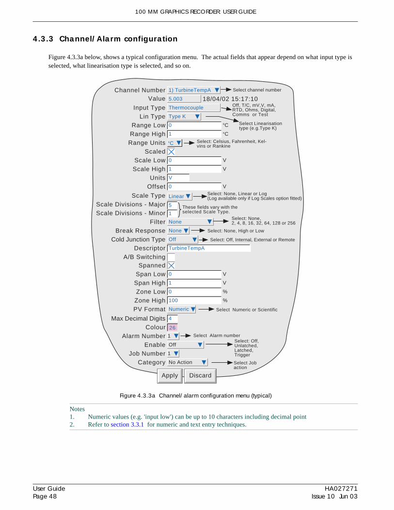
100 MM GRAPHICS RECORDER: USER GUIDE
HA027271Issue 10 Jun 03
User GuidePage 48
4.3.3 Channel/Alarm configuration
Figure 4.3.3a below, shows a typical configuration menu. The actual fields that appear depend on what input type isselected, what linearisation type is selected, and so on.
Figure 4.3.3a Channel/alarm configuration menu (typical)
Notes1. Numeric values (e.g. 'input low') can be up to 10 characters including decimal point2. Refer to section 3.3.1 for numeric and text entry techniques.
Apply Discard
Channel Number 1) TurbineTempA Select channel number
Input Type Thermocouple
Select Linearisationtype (e.g.Type K)
Lin Type Type K
Off, T/C, mV,V, mA,RTD, Ohms, Digital,Comms or Test
Range Low 0 C
Range High 1 C
Range Units C
ScaledScale Low 0 V
Scale High 1 V
Select: Celsius, Fahrenheit, Kel-vins or Rankine
Units V
Offset 0 V
Filter NoneSelect: None,2, 4, 8, 16, 32, 64, 128 or 256
Break Response None
Cold Junction Type Off
Descriptor TurbineTempA
Select: Off, Internal, External or Remote
SpannedSpan Low 0 V
Span High 1 V
Zone Low 0 %
Zone High 100 %
Max Decimal Digits 4
ColourAlarm Number 1
Enable Off
Job Number 1
Category No Action
Select: Off,Unlatched,Latched,Trigger
Select Jobaction
26
Select: None, High or Low
18/04/02 15:17:105.003Value
Scale TypeScale Divisions - MajorScale Divisions - Minor
Linear
5
1
Select: None, Linear or Log(Log available only if Log Scales option fitted)
These fields vary with theselected Scale Type.
PV Format Numeric
A/B Switching
Select Numeric or Scientific
Select Alarm number

100 MM GRAPHICS RECORDER: USER GUIDE
User GuidePage 49
HA027271Issue 10 Jun 03
4.3.3 CHANNEL/ALARM CONFIGURATION (Cont.)
Example: A type J thermocouple is used to measure a temperature range of 100 to 200 degrees Celsius. This thermo-couple output is transmitted to the recorder by a 4 to 20 mA transmitter, for display as an efficiency value between 0and 100%. In such a case, the following values would be set up:
Input type = milliampInput range low = 4.0
Input range high = 20.0Scale low = 0.0Scale high = 100Scale units = %
Linearisation range low = 100Linearisation range high = 200
Linearisation type units = degrees CLinearisation type = Type J thermocouple.Input shunt value = 250 ohms
Note: The following description shows all possible fields. The recorder itself edits the list and shows onlythose fields appropriate to the setup so far. For example, the 'Shunt' field appears only for mA input type.
CHANNEL NUMBERThe current channel and its descriptor are displayed. Touching the window area allows another channel to be selectedfor configuration.
VALUEThis field shows the current value of the selected channel along with either 'Unadjusted' or the time and date of adjust-ment.
INPUT TYPESelect thermocouple, millivolt, Volt, milliamp, RTD, Ohms, Digital (not channel 1),Slave Comms or Test as inputtype. Slave Comms must be selected if the channel is to be written-to via Modbus TCP..
LIN TYPEThe following linearisation tables are available as standard:
Linear, square root, x3/2, x5/2, UserLin1 to UserLin4 (see section 4.3.8 for details).Thermocouple types B, C, D, E, G2, J, K, L, N, R, S, T, U, NiMo/NiCo, Platinel, Ni/NiMo, Pt20%Rh/Pt40%RhResistance thermometer (RTD) types Cu
10, Pt
100, Pt
100A, JPT
100, Pt
1000, Ni
100, Ni
120, Cu
53.
For input ranges, accuracies etc. associated with the above thermocouple/RTD tables, see the specification section(Annex A) of this manual.
INPUT LOWEnter the lowest value to be applied to the input terminals (e.g.4.00).
INPUT HIGHEnter the highest value to be applied across the input terminals (e.g. 20.00).
SHUNTAllows a shunt resistor value to be entered for input type = mA. Commonly used values are 100 ohms and 250 ohms.Note that shunt resistors are connected to the input connector. The recorder cannot detect whether a shunt is fitted, orif one is, what value it has. Therefore it is the responsibility of the user to ensure that the ohmic value of any shuntfitted matches the shunt value entered in this field.

100 MM GRAPHICS RECORDER: USER GUIDE
HA027271Issue 10 Jun 03
User GuidePage 50
4.3.3 CHANNEL/ALARM CONFIGURATION (Cont.)
RANGE LOWEnter the lowest value of the required linearisation range (e.g. 100)
RANGE HIGHEnter the highest value of the required linearisation range (e.g. 200)
RANGE UNITSSelectable from degrees Celsius, degrees Fahrenheit, Kelvin or Rankine.
SCALEDThis box allows the user to select low and high values and units for a scale.
SCALE LOWEnter the scale value to correspond with input range low (e.g. 0).
SCALE HIGHEnter the scale value to correspond with input range high (e.g. 100).
SCALE UNITSEnter up to five characters of unit descriptor (e.g.%).
OFFSETAllows a fixed value to be added to or subtracted from the process variable. Recorder accuracy figures no longerapply if an offset is included.
SCALE TYPE This field allows 'None', 'Linear' or (if the Log Scales option is fitted), 'Log' to be selected as scale type. For linearscales, the number ofmajor/minor scale divisions can be selected. This does not affect the 'chart' grid divisions, whichis set up as a part of Group configuration (section 4.3.2).
NONEChannels with Scale Type selected to 'None', appear with no scale information in any display mode.
LINEAR Channels with Scale Type = Linear, appear with scale information in all display modes (except numeric). The numberof major and minor divisions can be selected from subsequent fields. Examples are shown in figure 4.3.3b, above.
LOG This menu item appears only if the Log Scales option is fitted.Channels with Scale Type = Log, appear with logarithmic scales. These scales have major divisions at each decadeboundary, and (space permitting), minor divisions for mantissa values 2 to 9. Examples are shown in figure 4.3.3b,below. Because of the nature of logarithms, neither negative values nor the value 0 can be used as scale 'zero'.
SCALE DIVISIONS - MAJORAppears for Linear Scale types only. Setting major divisions to 1, means that the scale consists only of 'zero' and fullscale. Setting Major divisions to 2, means that the scale has divisions at zero, 50% and full scale, and so on. Interme-diate scale values appear at major divisions if there is sufficient space.

100 MM GRAPHICS RECORDER: USER GUIDE
User GuidePage 51
HA027271Issue 10 Jun 03
Input
95%
3 xDamping
Recorderresponse
Effect of damping on stepchange in input signal
Figure 4.3.3c Channel filter
Channel 1
1000.0000
16.6441V
0.0000
5 minordivisions
Scale = Linear:Major divisions = 5; Minor divisions = 1
Scale = Linear:Major divisions = 5; Minor divisions = 5
Channel 1
1000.00
16.6441V
0.00 200.00 400.00 600.00 800.00
Channel 1
1000000.00
16.6441V
1.00
Scale = Log; 1 to 1000000Number format = Numeric
10.00 100.00 1000.00
Channel 1
1.00E3
16.6441V
1.00E0
Scale = Log; 1 to 1000Number format = Scientific
1.00E1 1.00E2
4.3.3 CHANNEL/ALARM CONFIGURATION (Cont.)
SCALE TYPE (Cont.)
SCALE DIVISIONS - MINORAppears for Linear Scale types only. Setting minor divisions to 1, means that the scale major divisions are not dividedi.e. no minor division tick marks appear . Setting Minor divisions to 2, means that each major scale division is di-vided into two, and so on. See figure 4.3.3b, below, for an example showing five minor divisions.
Figure 4.3.3b Scale Type examples
FILTERFor 'noisy' slowly changing signals, damping can be used to filter noise so that the underlying trend can be seen moreclearly. None, 2, 4, 8, 16, 32, 64, 128 or 256 seconds can be selected.
It is not recommended that damping be used on quickly changing signals.
Note that minor divisions andintermediate scale-valuesappear only if space allows

100 MM GRAPHICS RECORDER: USER GUIDE
HA027271Issue 10 Jun 03
User GuidePage 52
Break ResponseCold Junction Type
Remote CJ Temp fromDescriptor
NoneRemoteChannel 3 ˚CFurnace1 Temp
4.3.3 CHANNEL/ALARM CONFIGURATION (Cont.)
BREAK RESPONSEFor thermocouples and other low level inputs (i.e. input voltages less than 150mV), the recorder can be made to re-spond in one of the following ways, if a break in the input circuit is detected.None trace drifts with the input wiring acting as an aerial.Drive hi trace placed at full scaleDrive lo trace placed at scale 'zero'
COLD JUNCTION COMPENSATION (CJC)For input type = thermocouple, None, Internal, External or Remote can be selected for cold junction compensation.
INTERNALInternal CJC is by means of an RTD connected across pins 11 and 12 of the input board connector.
EXTERNALIf the cold junction is maintained (by the user) at a known, fixed tempera-ture, 'external' should be selected. An extra numeric entry box appears toallow the user to enter the temperature at which the cold junction is main-tained.
REMOTE'Remote' is selected if the cold junction temperature is to bemeasured by an external device connected to the instrument.An extra picklist appears which allows the user to select anyinput or maths channel to act as the cold junction temperaturesource channel. The temperature units displayed here, are those ofthe channel being configured, not those of the CJ source channel. The CJ source channel must be configured appropri-ately for the external device, and must provide a value which is consistent with the configured channel's units.
DESCRIPTORAllows a text string of up to 20 characters (including spaces) to be entered for the channel descriptor. (E.G. 'Turbine 2tempA').
A/B SWITCHING If enabled, this function allows alternative Span, Zone and Trace Colour values to be entered. 'A' values are usedduring normal operation. 'B' values are switched to by job action, as described in section 4.7
SPANNEDThis box, when selected, allows span low and high values to be entered. For example, in an input range of 0 to 600deg C, it may be that the temperature range between 500 and 600 degrees is of most interest. In such a case, settingspan low to 500 and span high to 600 will cause the recorder to display only that part of the input range, and this willfill the zone width which is selected next, effectively magnifying the area of interest.
If A/B switching is enabled, a second set of span low and span high values can be entered. 'A' values are used duringnormal operation. 'B' values are switched to by job action, as described in section 4.7.
Break ResponseCold Junction Type
External CJ TempDescriptor
NoneExternal0Furnace1 Temp

100 MM GRAPHICS RECORDER: USER GUIDE
User GuidePage 53
HA027271Issue 10 Jun 03
4.3.3 CHANNEL/ALARM CONFIGURATION (Cont.)
ZONEThis allows the portion of the chart which the channel occupies to be defined in terms of percent, where the left edgeof the chart is 0% and the right hand edge is 100%. For example, setting a low value of 50 and a high value of 100causes the channel trace to be confined to the right hand half of the chart.
If A/B switching is enabled, a second set of zone low and zone high values can be entered. 'A' values are used duringnormal operation. 'B' values are switched to by job action, as described in section 4.7.
PV FORMAT This allows the PV value, alarm setpoints, hysteresis values etc. to be displayed as normal numeric values (Numeric)or in 'Scientific' format (Scientific). When 'Scientific' is selected, values are displayed and entered as a decimalnumber between 1 and 10† (the mantissa), followed by a multiplier (the exponent). E.G. to enter a value of1244.5678, the value entered would be 1.2445678E3, where 3 represents the number of places that the decimal pointmust be shifted to the left in order to convert the value to a number between 1 and 10†. To enter a value of0.0004196, the entry would be 4.196E-4.
† Notes1. Strictly this is a number less than 10, as 10 would be 1.0E1.2. There must be at least one number after the decimal point.
MAXIMUM DECIMAL DIGITSThis defines the number of decimal places in the process value. Settable between zero and nine. Leading and trailingzeros are not displayed. Values too long for the available displaying width are truncated as described in section 3.
COLOURAllows the trace colour to be selected from a colour chart. Each of the 56 available colours is displayed with anumber, and it is this number which is entered. The background colour to the selection box changes to the selectedcolour.
If A/B switching is enabled, a second colour selection can be entered. Colour 'A' is used during normal operation.Colour 'B' is switched to by job action, as described in section 4.7

100 MM GRAPHICS RECORDER: USER GUIDE
HA027271Issue 10 Jun 03
User GuidePage 54
4.3.3 CHANNEL/ALARM CONFIGURATION (Cont.)
ALARM NUMBERAllows an alarm to be selected for configuration. (One or two for 16MB DRAM recorders; one to four for 32MBversions.)
ENABLEAllows the alarm to be defined as Off, Unlatched, Latched or Trigger
Off Alarm is disabled and the remainder of the alarm configuration is hidden.Unlatched Unlatched alarms become active when the trigger source becomes active and remain active
until the source returns to a non-active state.The indicator is on (flashing before acknowledgment - steady after acknowledgement) untilthe alarm clears.Alarm messages are printed if enabled in group configuration.
Latched Latched alarms become active when the trigger source becomes active and remain active untilthe alarm is acknowledged AND the trigger source has returned to a non-active state.The indicator is on (flashing before acknowledgment - steady after acknowledgement) untilthe alarm has been acknowledged AND the trigger source has returned to a non-active state.Alarm messages are printed if enabled in group configuration.Continuous jobs remain active only whilst the alarm trigger source is active. I.E. the jobfinishes when the alarm clears, whether acknowledged or not.
Trigger When triggered all associated jobs are initiated, and continuous jobs remain active until thealarm clears. There is no alarm indication, and no messages are printed.
TYPEThis field appears only when the alarm Enable is not selected Off. Each alarm can be defined as absolute high, abso-lute low, deviation-in, deviation-out, rate-of-change rise or rate-of-change fall.
Absolute High As shown in figure 4.3.3d, an absolute high alarm becomes active when the channel value exceeds thethreshold value. The alarm remains active until the channel value falls below (Threshold minus hyster-esis). If a dwell value is defined, the alarm does not become effective until this dwell time has been ex-ceeded.
Absolute Low As shown in figure 4.3.3d, an absolute low alarm becomes active when the channel value falls below thethreshold value. The alarm remains active until the channel value exceeds (Threshold + hysteresis). If adwell value is defined, the alarm does not become effective until this dwell time has been exceeded.
Deviation in As shown in figure 4.3.3e, a deviation-in alarm becomes active whenever the channel value enters theband: Reference ± Deviation. It remains active until the channel value leaves the band: Reference ± (De-viation + Hysteresis). If a dwell value is defined, the alarm does not become effective until this dwelltime has been exceeded.
Deviation out As shown in figure 4.3.3e, a deviation-out alarm is active whenever the channel value leaves the bandReference ± Deviation. It remains active until the channel value enters the band: Reference ± (Devia-tion - Hysteresis). If a dwell value is defined, the alarm does not become effective until this dwell timehas been exceeded.
Rate of change As shown in figure 4.3.3f, rate of change alarms become active whenever the signal value changes bymore than a specified amount within a specified period. If a dwell value is defined, the alarm does notbecome effective until this dwell time has been exceeded. An averaging period can be set to remove theeffects of sudden, but short-lived changes, such as noise spikes on the signal.
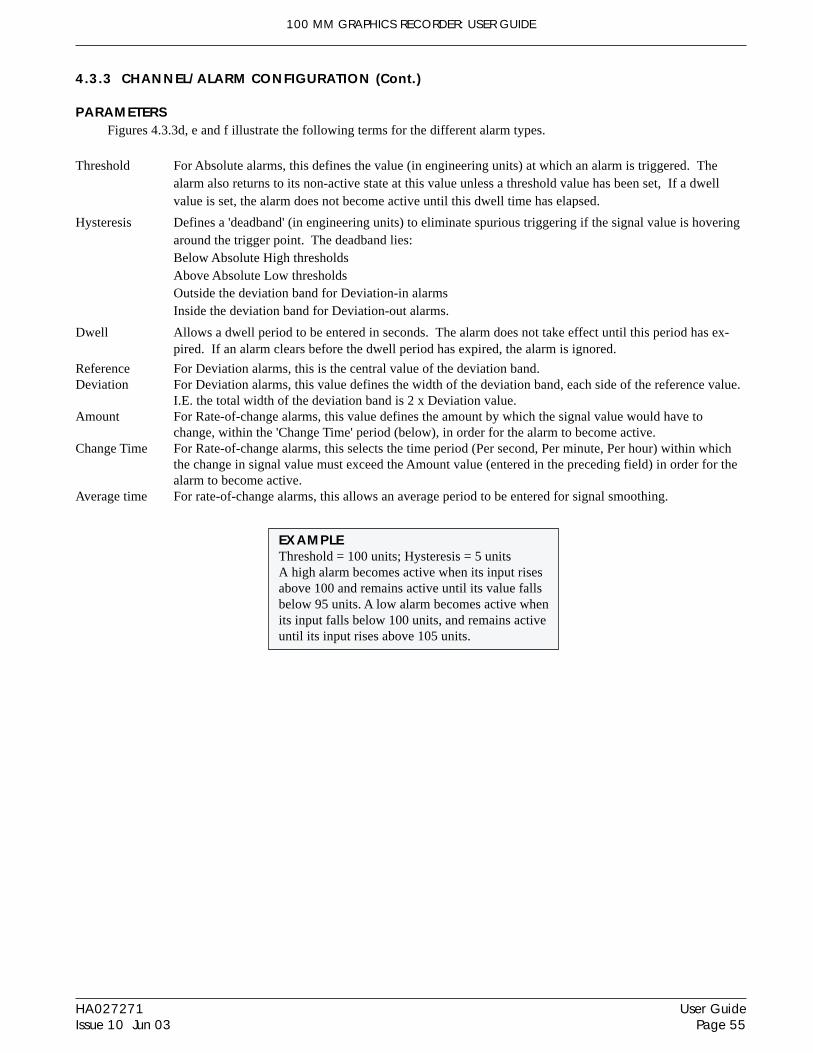
100 MM GRAPHICS RECORDER: USER GUIDE
User GuidePage 55
HA027271Issue 10 Jun 03
EXAMPLEThreshold = 100 units; Hysteresis = 5 unitsA high alarm becomes active when its input risesabove 100 and remains active until its value fallsbelow 95 units. A low alarm becomes active whenits input falls below 100 units, and remains activeuntil its input rises above 105 units.
4.3.3 CHANNEL/ALARM CONFIGURATION (Cont.)
PARAMETERSFigures 4.3.3d, e and f illustrate the following terms for the different alarm types.
Threshold For Absolute alarms, this defines the value (in engineering units) at which an alarm is triggered. Thealarm also returns to its non-active state at this value unless a threshold value has been set, If a dwellvalue is set, the alarm does not become active until this dwell time has elapsed.
Hysteresis Defines a 'deadband' (in engineering units) to eliminate spurious triggering if the signal value is hoveringaround the trigger point. The deadband lies:Below Absolute High thresholdsAbove Absolute Low thresholdsOutside the deviation band for Deviation-in alarmsInside the deviation band for Deviation-out alarms.
Dwell Allows a dwell period to be entered in seconds. The alarm does not take effect until this period has ex-pired. If an alarm clears before the dwell period has expired, the alarm is ignored.
Reference For Deviation alarms, this is the central value of the deviation band.Deviation For Deviation alarms, this value defines the width of the deviation band, each side of the reference value.
I.E. the total width of the deviation band is 2 x Deviation value.Amount For Rate-of-change alarms, this value defines the amount by which the signal value would have to
change, within the 'Change Time' period (below), in order for the alarm to become active.Change Time For Rate-of-change alarms, this selects the time period (Per second, Per minute, Per hour) within which
the change in signal value must exceed the Amount value (entered in the preceding field) in order for thealarm to become active.
Average time For rate-of-change alarms, this allows an average period to be entered for signal smoothing.

100 MM GRAPHICS RECORDER: USER GUIDE
HA027271Issue 10 Jun 03
User GuidePage 56
4.3.3 CHANNEL/ALARM CONFIGURATION (Cont.)
Figure 4.3.3d Absolute alarm definitions
Figure 4.3.3e Deviation alarm definitions
Figure 4.3.3f Rate-of-change alarm definitions
D
DD
Threshold
Hysteresis
Hysteresis: noDwell: 0 secs
D
= alarm activeD is in seconds up to 999999.Hysteresis is in engineering units
Hysteresis: noDwell: D secs
Hysteresis: yesDwell: 0 Secs
Hysteresis: yesDwell: D Secs
Input signal
Absolute low alarm definitionsAbsolute high alarm definitions
D
DD
Threshold
Hysteresis
Hysteresis: noDwell: 0 secs
D
= alarm activeD is in seconds up to 999999.Hysteresis is in engineering units
Hysteresis: noDwell: D secs
Hysteresis: yesDwell: 0 Secs
Hysteresis: yesDwell: D Secs
Input signal
symbol symbol
D D D DD D D D
ReferenceDeviation
Hysteresis: noDwell: 0 secs
D
= alarm activeD is in seconds up to 999999.Hysteresis is in engineering units
Hysteresis: noDwell: D secs
Hysteresis: yesDwell: 0 Secs
Hysteresis: yesDwell: D Secs
Input signal
D D D D
Deviation-in alarm definitions
Hysteresis
Deviation-out alarm definitionssymbolsymbol
Reference
Hysteresis
Hysteresis: noDwell: 0 secs
= alarm activeD is in seconds up to 999999.Hysteresis is in engineering units
Hysteresis: noDwell: D secs
Hysteresis: yesDwell: 0 Secs
Hysteresis: yesDwell: D Secs
Input signal
D D
Deviation
DeviationDeviation
Hysteresis
D D
D
D DD D D D
Am
ount
Change time units
Rate-of-change alarm definitions
Rise symbol Fall symbol
Presenttime
A rate-of-change alarm is active if the channel value changes by more than 1 amount unit in less than 1 timeunit. Dwell delays the alarm on time. Averaging removes the effects of spurious 'spikes'.
Rate-of-change rise active
Rate-of-change fall active
NowThen

100 MM GRAPHICS RECORDER: USER GUIDE
User GuidePage 57
HA027271Issue 10 Jun 03
4.3.3 CHANNEL/ALARM CONFIGURATION (Cont.)
JOB NUMBEROnly Job 1 is available
CATEGORYSelect the required job to be carried out when the channel is in alarm (e.g. Drive relay. See section 4.7 for Jobs de-scription.
WHILE/ONAllows the action of the job to be selected as:1. whilst active, whilst inactive or whilst unacknowledged or2. on becoming active, on becoming inactive or on acknowledgementaccording to job type.
Figure 4.3.3g, below, shows the various actions graphically. For 'While unacknowledged' and 'on acknowledgement'settings, two cases are shown, one where the alarm goes inactive before acknowledgement; the other where the alarmis acknowledged whilst the alarm is still active. The coloured (shaded) areas show the duration for which continuousjobs run; the down arrows show trigger points for 'one-shot' jobs. See section 3.1.3 for details of how to acknowledgealarms.
Figure 4.3.3g Graphical representation of job actions
ALARM MESSAGESAlarm on/off and alarm acknowledge message printing on the chart can be enabled/disabled as a part of 'Group con-figuration' described below. Alarms are acknowledged by touching the (flashing) alarm icon at the top of the screen,then touching the 'Ack all Alarms' key followed by the confirmation 'Yes' key (section 3.1.3).
Alarm triggerActive
Inactive
While active
While inactive
While unacknowledged(latching alarm)
While unacknowledged(non-latching alarm)
While unacknowledged(non-latching alarm)
Job goes inactive even ifalarm not yet acknowledged
While unacknowledged(latching alarm)
Job goes inactive even ifalarm still active
Alarm triggerActive
Inactive
On going active
On going inactive
On acknowledgement (latching alarm)
Acknowledge
On acknowledgement(non-latching alarm)
On acknowledgement(non-latching alarm)
Job triggers even if alarmnot yet acknowledged
On acknowledgement(latching alarm)
Job triggers even ifalarm still active
Acknowledge
Acknowledge
Acknowledge

100 MM GRAPHICS RECORDER: USER GUIDE
HA027271Issue 10 Jun 03
User GuidePage 58
4.3.4 Views Configuration
This part of the recorder's configuration allows groups to be set up (individually or globally) to include the variousdisplay modes described in section 3.4, above.
When enabled, display modes become selectable in the Root 'Goto View' menu.
Home Group and Home Page picklists allow a group and display mode to be defined for display when the Home keyis pressed in the Root menu.
Select Homedisplay mode forinstrument or forselected group
= Enabled
Home Time-outHome Group
Dark Trend BackgroundDark History Background
ScopeGroup
Display enableHome Page
Vertical TrendHorizontal Trend
Vertical BargraphHorizontal Bargraph
Numeric Page
1) Group 1
Apply Discard
0
Group
1) Group 1
Numeric Page
Select group forHome display
Select group fordisplay mode enable
These fieldsappear only if
Scope = 'Group'
Select Instrument or Group
Minutes
Figure 4.3.4a Views Configuration menu
HOME TIMEOUTThe recorder returns to the specified home page after the timeout value of minutes has elapsed since the last touch onthe display. Timout action is inhibited if a configuration is incomplete (there are changes which have not been 'Ap-plied'), or if a system-generated message (e.g. 'Clock Failure') is on display. User displays (e.g. Root menu) are time-out after approximately 50 seconds.
A value of zero disables the time-out function. Valid entries are between 1 and 99 minutes
HOME GROUPThis picklist allows a particular group to be selected for display when the root menu 'Home' key is pressed.
DARK TREND/DARK HISTORY BACKGROUNDThese tick boxes allow the user to select a black 'chart' for normal trending and/or trend history mode. These selec-tions act globally (i.e. on all groups) and are alternatives to the normal white-chart trend displays, not additional tothem.

100 MM GRAPHICS RECORDER: USER GUIDE
User GuidePage 59
HA027271Issue 10 Jun 03
4.3.4 VIEWS CONFIGURATION (Cont.)
SCOPEThe remaining items of Views configuration can be selected to act globally (Instrument) or to act on individual groups(Group). When 'Instrument' is selected, enabled display modes appear in all groups' Root 'Goto View' menu (Figure4.3.4b). When 'Group' is selected, each group can be set up with its own active display modes.
For the particular group on display, the Root menu 'Goto View' key used to select the required display modes fromthose which have been enabled. Display modes which are not enabled are 'greyed' in this menu..
GROUPThis field appears only if 'Scope' is set to 'Group', and allows each group to be selected for display configuration. Forother items of Group Configuration see section 4.3.2.
Note: Group 1 is a standard recorder feature. Group 2 is an optional extra.
DISPLAY ENABLEDThis field appears only if 'Scope' is set to 'Group', and allows the selected group to be enabled or disabled for display.When enabled, the group can be displayed by using the 'Root menu/Goto Group/Group N' selection. When disabled,the group is 'greyed' in the 'Root menu/Goto screens/Group N' selection. It is not possible to disable the Home group.
HOME PAGEAllows a particular display mode to be selected as the default display, either for all groups (Scope = instrument) or ona group-by-group basis (Scope = group).
DISPLAY MODE ENABLINGA series of check boxes allow the various display modes to be added to (or removed from) the Root menu 'Goto View'menu (figure 4.3.4b), either for all groups (Scope = instrument) or on a group-by-group basis (Scope = group). It isnot possible to disable the selected Home page mode.
Figure 4.3.4b Goto View menu
Options
Goto Group
Operator
Login
Goto View
Home
File
Root menu
Engineer
Vertical Trend Horizontal Trend
Vertical Bargraph Horizontal Bargraph
Numeric Page Alarm Summary
Goto View: Group 1
Message Log
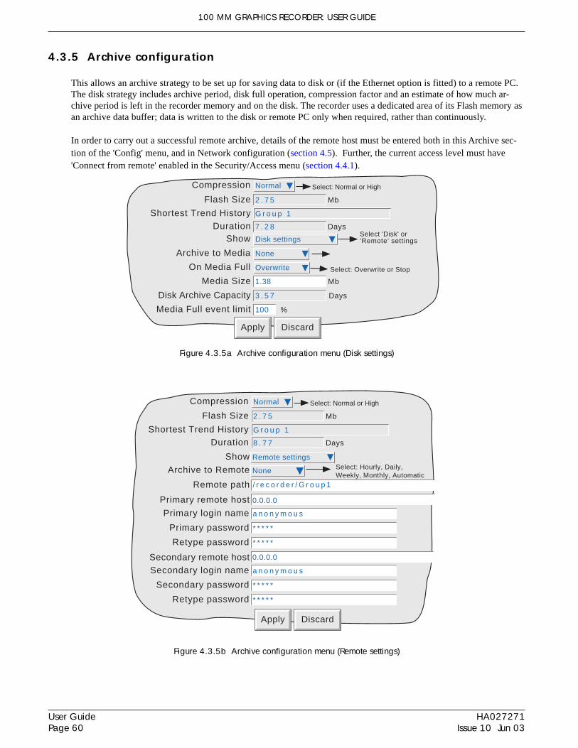
100 MM GRAPHICS RECORDER: USER GUIDE
HA027271Issue 10 Jun 03
User GuidePage 60
4.3.5 Archive configuration
This allows an archive strategy to be set up for saving data to disk or (if the Ethernet option is fitted) to a remote PC.The disk strategy includes archive period, disk full operation, compression factor and an estimate of how much ar-chive period is left in the recorder memory and on the disk. The recorder uses a dedicated area of its Flash memory asan archive data buffer; data is written to the disk or remote PC only when required, rather than continuously.
In order to carry out a successful remote archive, details of the remote host must be entered both in this Archive sec-tion of the 'Config' menu, and in Network configuration (section 4.5). Further, the current access level must have'Connect from remote' enabled in the Security/Access menu (section 4.4.1).
Figure 4.3.5a Archive configuration menu (Disk settings)
Figure 4.3.5b Archive configuration menu (Remote settings)
Apply Discard
Archive to Media
On Media Full
Compression
None
Media Size 1.38 Mb
Overwrite
Normal
Flash Size 2 . 7 5 Mb
Disk Archive Capacity 3 . 5 7 Days
Shortest Trend History G r o u p 1
Select: Overwrite or Stop
Select: Normal or High
Show Disk settingsSelect 'Disk' or'Remote' settings
Duration 7 . 2 8 Days
Media Full event limit 100 %
Apply Discard
Archive to Remote None Select: Hourly, Daily,Weekly, Monthly, Automatic
Remote path
Show Remote settings
0.0.0.0Primary remote host
Primary login name a n o n y m o u s
Primary password * * * * *
Retype password * * * * *
0.0.0.0Secondary remote hostSecondary login name a n o n y m o u s
Secondary password * * * * *
Retype password * * * * *
/ r e c o r d e r / G r o u p 1
Compression Normal
Flash Size 2 . 7 5 Mb
Shortest Trend History G r o u p 1
Select: Normal or High
Duration 8 . 7 7 Days
100 MM GRAPHICS RECORDER: USER GUIDE
User GuidePage 61
HA027271Issue 10 Jun 03
4.3.5 ARCHIVE CONFIGURATION (Cont.)
COMPRESSIONSelect Normal or high compression. 'Normal' compresses the data but still provides an exact copy. 'High' compressesmore, but channel values are saved only to 1 part in 108 resolution.
FLASH SIZEAllows the size of the Flash memory to be viewed by the user.
SHORTEST TREND HISTORY / DURATIONThis shows which group has the shorter amount of Flash memory allocated to its history record. Providing the ar-chive period is less than the value displayed in the Duration window, no data will be lost from either group. If thearchive period is greater than this value, then some of the data in one or both groups will have been overwritten andtherefore lost.
If both groups have the same Shortest Trend History Duration, Group 1 is displayed.
Note: Trend history duration depends on many factors, as described in Group Configuration (section 4.3.2).above.
SHOWThis allows the fields which are to appear below 'Show' to be applicable to disk (Disk Settings), or to the setting up ofa remote host path for archiving purposes (Remote settings). The following descriptions contain all the fields whichmay appear in either menu.
ARCHIVE TO MEDIANone Archive to disk is initiated by the operator (section 4.1)Hourly Archive to disk occurs on the hour every hourDaily Archive to disk occurs at 00:00* hrs each dayWeekly Archive to disk occurs at 00:00* hrs every MondayMonthly Archive to disk occurs at 00:00* hrs on the 1st of each monthAutomatic The recorder selects the slowest out of Hourly, Daily, Weekly or Monthly, which is guaranteed not to
lose data. This is calculated according to which of the trend history buffer or the disk is the smaller. Therecorder assumes that the disk is 'empty' when making these calculations.
*Note: Archive times are not adjusted for Daylight Saving hour changes. Thus if the archive is set to 'daily','weekly' or ' monthly' then, during 'Summer Time', the archive will occur an hour late (i.e. at 01:00 hrs. insteadof midnight).
MEDIA FULL OPERATIONFor Disk Settings only:Overwrite Oldest data replaced with latest data when disk is fullStop Archiving stops when the disk is full
Notes1. The maximum number of history files (total for both groups) is 750 per directory.2. When in 'Overwrite' mode, the recorder will overwrite only those files which it has itself created. Thus, if
a disk is inserted which contains history files from another recorder, these cannot be overwritten. The filenames are of the form UUU....UUUIIIIIIFFGGSSSSSS, where IIIIII represent the lowest threebytes of MAC address of the recorder which created the file (see section 4.5.1). It is not possible for theuser to delete files created by another instrument (i.e. one with another MAC address).

100 MM GRAPHICS RECORDER: USER GUIDE
HA027271Issue 10 Jun 03
User GuidePage 62
4.3.5 ARCHIVE CONFIGURATION (Cont.)
MEDIA SIZEFor Disk Settings only, allows the size of the Disk to be entered, for user information only. This item is not saved aspart of the configuration.
DISK ARCHIVE CAPACITYFor Disk Settings only, this gives an estimated time to fill the disk, based on the archive rate, the compression ratio,the disk size and on the exact nature of the data. (Rapidly changing values use more space than static/slowly changingvalues.)
MEDIA FULL EVENT LIMIT For disk settings only, this allows the user to specify a percentage-full value for the disk or pc card, at which theevent source 'Archive media % full' is triggered. The event remains active until the disk or pc card is replaced, or hasdata removed from it to make more room available.
ARCHIVE TO REMOTE
Note: Archive to remote is available only if the Ethernet option is fitted
For Remote settings only:None Archive to host is initiated by the operator (section 4.1.2)Hourly Archive to host occurs on the hour every hourDaily Archive to host occurs at 00:00* hrs each dayWeekly Archive to host occurs at 00:00* hrs every MondayMonthly Archive to host occurs at 00:00* hrs on the 1st of each monthAutomatic The recorder selects the slowest out of ‘Hourly’, Daily, Weekly or Monthly, which is guaranteed not to
lose data (depends on the size of the Trend History Buffer).
*Note: Archive times are not adjusted for Daylight Saving hour changes. Thus if the archive is set to 'daily','weekly' or ' monthly' then, during 'Summer Time', the archive will occur an hour late (i.e. at 01:00 hrs. insteadof midnight).
REMOTE PATHFor Remote settings only:The route to a folder or directory on the remote host, set up as a part of that host’s FTP configuration
PRIMARY REMOTE HOSTFor Remote settings only:If a Domain Name Service (DNS) is specified in the Network key ‘Name’ page (fig 4.5.2), then the Primary RemoteHost is the server name. If DNS is not selected, then the Primary Remote Host is the IP address of the remote host,set up in the host’s Control Panel\Network.
PRIMARY LOGIN NAME/PASSWORDFor Remote settings only:Login name and password of the remote host account assigned either by the Network administrator, or in the Guestaccount of the remote host’s FTP services or User Manager configuration. The password, which must be of betweeneight and 20 characters, must be entered twice to ensure integrity.
SECONDARY REMOTE HOST/LOGIN/PASSWORDFor Remote settings only:As for primary versions, but for a secondary host. The secondary route is used only if the primary route fails.
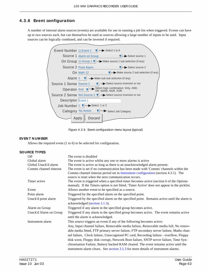
100 MM GRAPHICS RECORDER: USER GUIDE
User GuidePage 63
HA027271Issue 10 Jun 03
4.3.6 Event configuration
A number of internal alarm sources (events) are available for use in running a job list when triggered. Events can haveup to two sources each, but can themselves be used as sources allowing a large number of inputs to be used. Inputsources can be logically combined, and can be inverted if required.
Figure 4.3.6 Event configuration menu layout (typical)
EVENT NUMBERAllows the required event (1 to 6) to be selected for configuration.
SOURCE TYPESOff The event is disabledGlobal alarm The event is active whilst any one or more alarms is activeGlobal Unack'd alarm The event is active as long as there is an unacknowledged alarm present.Comms channel timeout The event is set if no communication has been made with 'Comms' channels within the
Comms channel timeout period set in Instrument configuration (section 4.3.1). Thesource is reset when the next communication occurs.
Timer active The event is triggered when a specified timer becomes active (section 6 of the Optionsmanual). If the Timers option is not fitted, 'Timer Active' does not appear in the picklist.
Event Allows another event to be specified as a source.Point alarm Triggered by the specified alarm on the specified point.Unack'd point alarm Triggered by the specified alarm on the specified point. Remains active until the alarm is
acknowledged (section 3.1.3).Alarm on Group Triggered if any alarm in the specified group becomes active.Unack'd Alarm on Group Triggered if any alarm in the specified group becomes active. The event remains active
until the alarm is acknowledged.Instrument alarm This source triggers an event if any of the following becomes active:
Any, Input channel failure, Removable media failure, Removable media full, No remov-able media fitted, FTP primary server failure, FTP secondary server failure, Maths chan-nel failure, Clock failure, Unrecognised PC card, Recording failure - overflow, Floppydisk worn, Floppy disk corrupt, Network Boot failure, SNTP server failure, Time Syn-chronisation Failure, Battery backed RAM cleared. The event remains active until theinstrument alarm clears. See section 3.1.3 for more details of instrument alarms.
Apply Discard
Select 1 to 6Event Number 1) Event 1
Source 1
Descriptor Event 1
Select: 1 or 2Job Number 1
Category No Action Select Job Category
Alarm on Group Select source 1
On Group 1) Group 1
Source 2 Point Alarm Select source 2
On Math 12
Alarm 2
Source 1 Sense
Operator
Source 2 Sense
Source 1
And
Not Source 2
Make sub-sub selection (if any)
Select logic combination: Only, AND,OR, NAND, NOR, XOR.
Select source inversion or not
Select source inversion or not
Make source 1 sub selection (if any)
Make source 2 sub selection (if any)

100 MM GRAPHICS RECORDER: USER GUIDE
HA027271Issue 10 Jun 03
User GuidePage 64
4.3.6 EVENT CONFIGURATION (Cont.)
EVENT SOURCES (Cont.)
Power up A transient event is triggered at power up.Maths channel partial failure For recoders fitted with the Maths pack option, this event is set if, say, one of the inputs
to a group averaging function becomes invalid. In such a case, the average will be calcu-lated on the remaining input values, but the result may not be as accurate as expected.Loss of one input can also be important in functions such as Fvalue, where several sen-sors may be distributed within the load and their outputs used in a group minimum calcu-lation for input into the Fvalue equation.
Battery Low This event is set when the battery is reaching the end of its useful life. The event re-mains active until the battery is replaced.
Archive media % full Triggered when the floppy disk or PC card has reached the % fullness defined in Archiveconfiguration (section 4.3.5).
Invalid Password Entry Transient event at the point of an invalid password entry attemptUser Logged In This event becomes active whenever a user with the specified Event Permission logs in.
The event remains active until all local and remote users, with the specified permission,have logged out. See also section 4.4.1 (Access levels).
Event Button Not applicable this release.
SOURCE 1 SENSE Allows source 1 to be used in its normal sense (Select 'Source 1') or inverted (Select 'Not Source 1').
Example: Source 1 is alarm 1 on channel 3With Source 1 Sense = Source 1, the event is active whenever channel 3 alarm 1 is active.With Source 1 Sense = Not Source 1, the event is active whenever the alarm is not active.
OPERATOR This allows a logical combination of input sources to be used to trigger an event. The selections and their definitionsare shown in table 4.3.6, below.
Table 4.3.6 Logical operators for event sources
SOURCE 2 SENSE Allows source 2 to be used in its normal sense (Select 'Source 2') or inverted (Select 'Not Source 2').
Example: Source 2 is Group 1 Batch RunningWith Source 2 Sense = Source 2, the event is active whilst the batch is running.With Source 2 Sense = Not Source 2, the event is active whilst the batch is not running.
Operator Event active when: Event not active when:
Only S1 Active S1 not active
AND S1 and S2 both active S1 and/or S2 not active
OR S1 and/or S2 active S1 and S2 both not active
NAND S1 and/or S2 not active S1 and S2 both active
NOR S1 and S2 both not active S1 and/or S2 both active
XOR S1 or S2 activeS1 and S2 both active or both not
activeS1 = Source 1; S2 = Source 2

100 MM GRAPHICS RECORDER: USER GUIDE
User GuidePage 65
HA027271Issue 10 Jun 03
4.3.6 EVENT CONFIGURATION (Cont.)
DESCRIPTORAllows a text string to be entered as the event title. See section 3.3.1 for text entry techniques.
JOB NUMBEROnly Job 1 is available.
CATEGORYSelect the required event job to be carried out (e.g. Drive relay). See section 4.7 for Jobs description.
WHILE/ONAllows the action of the alarm job to be chosen asa. whilst active, whilst inactive or whilst unacknowledged for continuous jobs (e.g. drive relay), or,b. on going active, on going inactive or on acknowledgement for 'one-shot' jobs (e.g. increment counter).See also figure 4.3.3g and associated text.
EVENT EXAMPLEAn event is to be active whenever Channel 1 Alarm 1 is active whilst Channel 3 alarm 2 is not active.
Source 1 = Point alarm (On = Channel 1; Alarm = 1)Source 2 = Point alarm (On = Channel 3; Alarm = 2)Source 1 Sense = Source 1Operator = AndSource 2 Sense = Not Source 2
It is possible to achieve the same result by inverting both Source senses and using the Nor operator.

100 MM GRAPHICS RECORDER: USER GUIDE
HA027271Issue 10 Jun 03
User GuidePage 66
4.3.7 Messages
This feature allows up to 12 messages to be sent, by job action (section 4.7), to the display, to a specified group or toall groups. The messages are of the form: Date, Time, Message. The message can be just text (up to 40 characters),or can include up to six descriptors, instantaneous values etc. These ‘embedded strings’ are typed into the message as1 to 6, with 1 to 6 being defined, from picklists, as Blank, Source Descriptor, Specified Descriptor, Source Valueor Specified Value.
If a Group-destination message contains more characters than can be displayed on the screen (approximately 57 in-cluding time and date), the right-hand part of the message is invisible to the user. The message appears in full whenReview Software is used. Display-destination messages are always fully visible.
MESSAGE ENTRYThe message configuration page is shown below in figure 4.3.7. The page is accessed from the Root menu/Operator/Config menu.
Figure 4.3.7 Message entry configuration page.
CONFIGURABLE PARAMETERS
Message Number Select Message 1 to Message 12 from picklist.Message Enter message by using pop-up keyboards (section 3.1.1)Replace n with A picklist selection of ‘Blank’, Source Descriptor, Source Value, Specified Descriptor or Specified
value.Source Descriptor: The descriptor of the source which triggers the job message.Source Value: The instantaneous value of the source at trigger time.Specified Descriptor: Produces a further field ‘n source’, described below.Specified Value: Produces a further field ‘n source’, described below.
n source This field appears only if the previous field (Replace n with) is selected as ‘Specified Descrip-tor’ or ‘Specified Value’. The associated picklist contains the descriptors of all the channels, mathschannels, totalisers etc. in the recorder. It is thus possible to configure, say alarm 1 on channel 2,to produce a message giving the descriptor and/or value of, say, totaliser 1
Notes:1. n = 1 to 62. the example below is intended to clarify message entry techniques.
Message NumberMessage
Replace 1 with
Replace 2 with
Replace 3 with3 source
Replace 4 with4 source
Replace 5 with
Apply Discard
Select:Source Descriptor,Source Value,Specified Descriptor,Specified Value orBlank
Replace 6 with
1) The value of
The value of 1 = 2 & 3 = 4
Source Descriptor
Source Value
Totaliser 1
Specified Descriptor
Totaliser 1
Specified Value
Blank
Blank
Select:Channel/totaliser etc.whose descriptor/valueis to be inserted
Select Message 1 to 12for configuration
100 MM GRAPHICS RECORDER: USER GUIDE
User GuidePage 67
HA027271Issue 10 Jun 03
4.3.7 MESSAGES (Cont.)
EXAMPLE
To configure Message 2 to read “The value of Chan 2 = (Value channel 2) & Tot 1 = (Value totaliser 1)”
Before configuring the message:In channel configuration:
Set Channel 2 descriptor to: Chan twoSet Channel 2 alarm job to:
Category: MessageSend message(s) to: All Groups
First message: 2) Message 2Last Message: 2) Message 2
On: ActiveIn Totaliser configuration:
Set Totaliser 1 descriptor to: Tot one
To configure the message:1. Select Message 2.2. Access the Symbols keyboard (section 3.3.1) and enter, without spaces, =&=
3. Access the Numeric keyboard and insert 1, 2, 3, 4 within the braces to give: 1=2&3=4
4. Access the Alphabet keyboard, and insert text and spaces: The value of 1 = 2 & 3 = 45. Set ‘Replace 1’ to “Source Descriptor’6. Set ‘Replace 2’ to ‘Source Value’7. Set ‘Replace 3’ to ‘Specified Descriptor’8. Set ‘3 source’ to Tot one9. Set ‘Replace 4’ to ‘Specified Value’10. Set ‘4 source’ to ‘Tot one’
The result of this is that, should the channel 2 alarm go active, the following message would be sent to all groups,appear on the ‘chart’ and become part of all groups’ histories:
18/10/01 11:19:58 The value of Chan two = 6.0˚C & Tot one = 338[3.8073 Units]
The part in square brackets is outside the visible area (shaded in the examples) of the screen. The totaliser value canbe found, in such cases, by1. Entering history, as described in section 3.4.1 of this manual,2. Setting the cursor to the time appearing in the message3. Selecting the ‘Tot one’ faceplate4. Reading the value.
Alternatively, more of the message can be made visible by shortening the descriptors (to Ch2 and Tot1, for example):
18/10/01 11:19:58 The value of Ch2 = 6.0˚C & Tot1 = 3383.8073 U[nits]
and/or removing ‘The value of’ (leaving only 1=2&3=4):
18/10/01 11:19:58 Ch2 = 6.0˚C & Tot1 = 3383.8073 Units

100 MM GRAPHICS RECORDER: USER GUIDE
HA027271Issue 10 Jun 03
User GuidePage 68
4.3.8 User Linearisation Tables
The Channel configuration item 'Lin Type' includes four linearisation tables called, initially, UserLin1 to UserLin4.This User Linearisation part of the instrument configuration allows the user to enter a linearisation look-up table ofbetween two and 66 pairs of points.
The pairs of points are entered as X1Y1, X2Y2... ...XnYn,where 'n' is the specified number of points.X1 to Xn represent the inputs to the function.Y1 to Yn represent the corresponding outputs from the function.
Notes:1. Each Y value must be unique - i.e. there cannot be more than one X value with the same Y value assigned
to it.2. Each X value (other than the first) must be greater than the previous one3. Each Y value (other than the first) must be greater than the previous one
The import/export Linearisation tables feature described in 'Save/Restore' (section 4.2) offers an alternative way ofentering linearisation tables.
Figure 4.3.8a shows the default configuration page. Figure 4.3.8b shows a simple table for relating water depth towater volume for a cylindrical tank with a conical bottom.
Figure 4.3.8a User linearisation configuration page
CONFIGURATION PARAMETERS User Linearisation Allows one of the four user linearisation tables to be selected for configuration.Descriptor Allows the user to enter a name of up to 20 characters (including spaces) for the table.Format This allows the point pair values to be entered as normal numeric values (Numeric) or in
'Scientific' format (Scientific). When 'Scientific' is selected, values are displayed and enteredas a decimal number between 1 and 10† (the mantissa), followed by a multiplier (the expo-nent). E.G. to enter a value of 1244.5678, the value entered would be 1.2445678E3, where 3represents the number of places that the decimal point must be shifted to the left in order toconvert the value to a number between 1 and 10†. To enter a value of 0.0004196, the entrywould be 4.196E-4. Figure 4.3.8b, below, gives further examples.
† Notes1. Strictly this is a number less than 10, as 10 would be 1.0E1.2. There must be at least one number after the decimal point.
User Linearisation
Descriptor
Format
Number of Points
X1
Y1
X2
3) UserLin3
Numeric
2
0
0
1
Apply Discard
Y2 1
UserLin3Select Numericor Scientific

100 MM GRAPHICS RECORDER: USER GUIDE
User GuidePage 69
HA027271Issue 10 Jun 03
4.3.8 USER LINEARISATION TABLES (Cont.)
Number of points This is used to enter the total number of point pairs in the table. The following XY fieldsincrease in number up to the entered value. (A scroll bar appears if there are more points thancan be displayed in the available screen height.)
X1 to XN The input values to the table, where N is the 'Number of Points' entered above.Y1 to YN The resulting, corresponding output values from the look-up table.
6.5
me
tre
s
3 metres
2 metres
10
20
30
40
50
60
Vo
lum
e (
cub
ic m
etr
es)
0
1 2 3 4 5 6 7 8 9
Depth (metres)
0
1 0 0.0 0.0E0 0.0E02 0.5 0.074 0.5E0 7.4E-23 1 0.589 1.0E0 5.89E-14 1.5 1.988 1.5E0 1.988E05 2 4.712 2.0E0 4.712E06 3 11.771 3.0E0 1.1771E17 4 18.840 4.0E0 1.8840E18 5 25.908 5.0E0 2.5908E19 6 32.977 6.0E0 3.2977E110 7 40.045 7.0E0 4.0045E111 8 47.114 8.0E0 4.7114E112 8.5 50.648 8.5E0 5.0648E1
Numeric ScientificPointpair X Y X Y
X
Y
Figure 4.3.8b Sample User Linearisation table
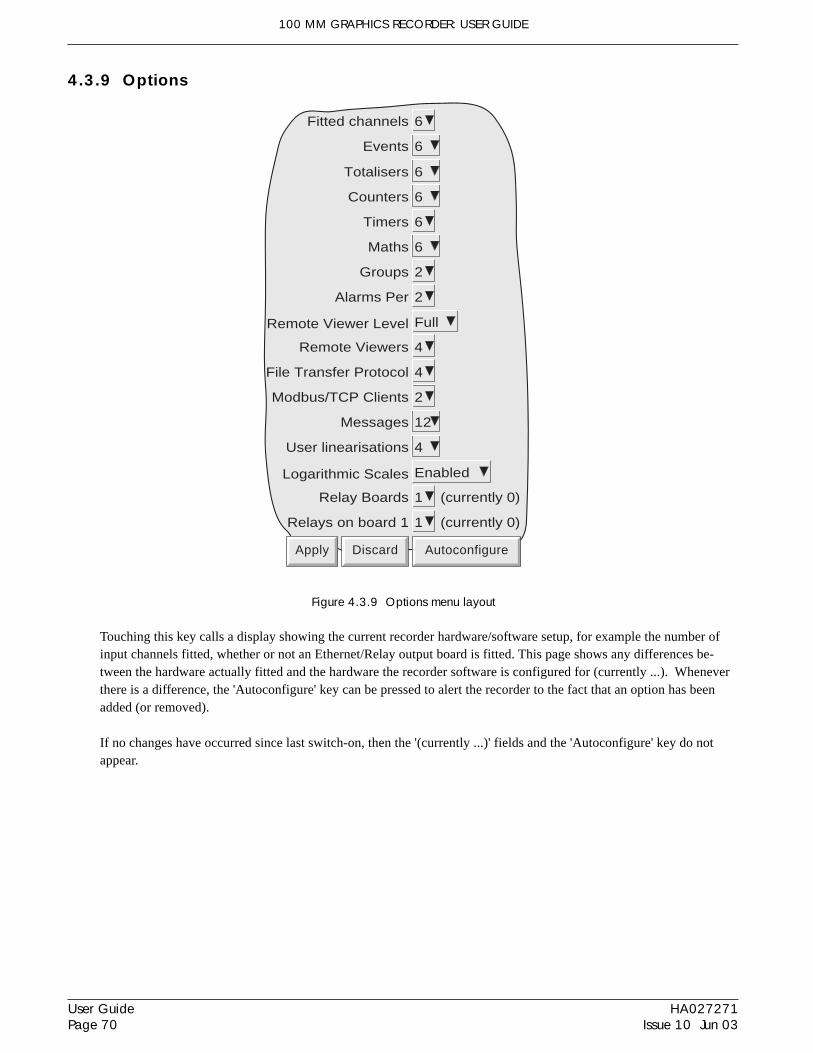
100 MM GRAPHICS RECORDER: USER GUIDE
HA027271Issue 10 Jun 03
User GuidePage 70
4.3.9 Options
Figure 4.3.9 Options menu layout
Touching this key calls a display showing the current recorder hardware/software setup, for example the number ofinput channels fitted, whether or not an Ethernet/Relay output board is fitted. This page shows any differences be-tween the hardware actually fitted and the hardware the recorder software is configured for (currently ...). Wheneverthere is a difference, the 'Autoconfigure' key can be pressed to alert the recorder to the fact that an option has beenadded (or removed).
If no changes have occurred since last switch-on, then the '(currently ...)' fields and the 'Autoconfigure' key do notappear.
Fitted channels 6
Apply Discard Autoconfigure
(currently 0)
Remote Viewers 4
File Transfer Protocol 4
Modbus/TCP Clients 2
Messages 12
Relay Boards 1
Relays on board 1 1 (currently 0)
Totalisers 6
Counters
Timers 6
Maths 6
Groups 2
6
Remote Viewer Level Full
User linearisations 4
Logarithmic Scales Enabled
Events 6
Alarms Per 2

100 MM GRAPHICS RECORDER: USER GUIDE
User GuidePage 71
HA027271Issue 10 Jun 03
FredAccess whenNew Password
Retype PasswordConnect from remote
Login Disabled
Change Alarm Setpoints
Set Clock
Archiving ControlSave/Restore
Paste/Delete FilesFull Configuration
Full Security
Apply Discard
Edit own Password
**
**
Edit Maths Constant
Preset Counters
Adjust Inputs
Access (Section 4.4.1)
Acknowledge Alarms
Reset MathsPreset Totalisers
Start/Reset Timers
Event Permission 1Event Permission 2Event Permission 3Event Permission 4Event Permission 5
Force Change of Password
New UserNew Password
Retype Password
Based On Operator
Apply Discard
Add
Add User (Section 4.4.2)
EngineerUser
Select the required access level and enter thepassword if required
Logout
User Fred
Apply Discard
Remove
Remove User(Section 4.4.3)
Login (Section 3.3.1)
Archive SystemSave/R.. Config Security Network
Login
Access
Add user
Remove User
4.4 SECURITY
Touching this key allows the operator to select 'Login' (described in section 3.3.1) 'Access' or 'Add/Remove User' forconfiguration. Selecting 'Access' displays the current user level. Touching this area allows the user to select 'Loggedout', 'Operator', 'Engineer' or any added users. The user may also go directly to logged out mode by operating the'Logout' key.
Figure 4.4 Security configuration menus
4.4.1 Access levels
There are essentially three levels of security associated with the recorder viz: Engineer, Operator and Logged out.(The fourth level - Service - is available only to service engineers). When logged-in at engineer level, the user canset access permissions for Operator and logged-out levels, and can edit Operator and Engineer level passwords. Thepassword for both Engineer and Operator levels is set to 10 at the factory.
Note: Setting the password to 'blank' allows subsequent access without a password having to be entered.
Users with Full Security permission can Add (and Delete) users (sections 4.4.2, 4.4.3) and assign them individualpasswords and access permissions. User names (IDs) appear in the 'Login' and 'Access When' picklists.

100 MM GRAPHICS RECORDER: USER GUIDE
HA027271Issue 10 Jun 03
User GuidePage 72
4.4.1 ACCESS LEVELS (Cont.)
SETTING PERMISSIONSOnce logged in at Engineer level, operate the 'Security' key and select 'Access'. A page similar to that shown in fig-ure 4.4.1 appears, allowing the permissions to be set for the various access level and for individual users. The list ofparameters is the same for all access levels except for 'Logged out', for which the password parameters and 'logindisabled' items do not appear.
Figure 4.4.1 Access permissions menuACCESS WHEN:
Allows an access level or an individual user ID to be selected from a pick list.
NEW PASSWORD/RETYPE PASSWORDFor all levels except Logged Out, these fields allow a new password to be entered for the selected access level orUser. The password must be entered in the 'Re-type Password' field. If the two differ, a warning message (Passwordsdid not match) appears when the APPLY key is operated, and password entry must be repeated.
CONNECT FROM REMOTEEnabling this field, calls the Remote user name and Remote user password entry boxes.
FredAccess whenNew Password
Retype PasswordConnect from remote
Login Disabled
Change Alarm Setpoints
Set Clock
Archiving ControlSave/Restore
Paste/Delete FilesFull Configuration
Full Security
Apply Discard
Edit Own Password
Remote user name Fred
Remote password
**
**
Retype remote password
Acknowledge Alarms
Reset Maths
Password functions donot appear for 'Logged-out' level of access.
Remote user fieldsappear only if 'Connect
from remote' is enabled
Password functions donot appear for 'Logged-out' level of access.
These fields appear only if therelevant options are fitted
Adjust Inputs
Edit Maths Constant
Preset Totalisers
Preset CountersStart/Reset Timers
Event Permission 1Event Permission 2Event Permission 3Event Permission 4Event Permission 5
Force Change of Password
100 MM GRAPHICS RECORDER: USER GUIDE
User GuidePage 73
HA027271Issue 10 Jun 03
4.4.1 ACCESS LEVELS (Cont.)
REMOTE USER NAME/PASSWORDThese two entry boxes allow user name and password to be entered for use by the remote host operator. The remoteuser will be able to access the recorder configuration according to the other access permissions enabled in this page.The password must be entered twice to ensure integrity.
To allow unrestricted view-only to the host, 'Logged out' permission level should be selected and then a user name of‘anonymous’ entered, and the password field left blank.
Note: Remote login will be refused if the user account is disabled for any reason.
LOGIN DISABLEDFor all levels except Logged Out, this allows any one or more of the access levels do be removed from the 'Accesswhen' picklist.
Note: This feature should be used with discretion, or the situation might arise in which the recorder cannot belogged onto, either at a particular access level or at all. It is recommended that at least one user with Engi-neer-level access is retained with login enabled, or it may become necessary to return the recorder to themanufacturer, or to arrange for a service visit.
EDIT OWN PASSWORDAllows each user, with this permission enabled, to edit his/her password.
CHANGE ALARM SETPOINTSAllows each user with this permission enabled, to edit alarm parameters under Configuration/Channel
ACKNOWLEDGE ALARMSAllows each user with this permission enabled, to acknowledge alarms (section 3.1.3)
EDIT MATHS CONSTANTThis field appears only for recorders with the Maths option.
If one or more maths channels are configured with function 'Constant', then with this permission set, the user may editthe constant value(s). See section 3 of the Options Manual for further details
PRESET TOTALISERSThis field appears only for recorders with the Totaliser option.
Enabling this function allows the user to preset the totaliser value. See section 4 of the Options Manual for furtherdetails.
SET CLOCKAllows each user, with this permission enabled, to set the recorder time and date functions under System/Clock
ADJUST INPUTS Allows the user to adjust recorder readings, as described in section 4.6.4, below.
ARCHIVING CONTROLAllows each user, with this permission enabled, full access to disk archive control.
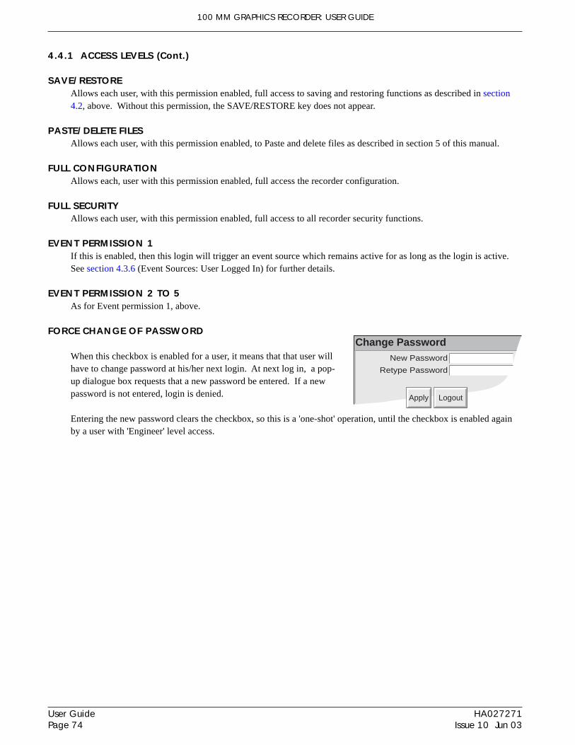
100 MM GRAPHICS RECORDER: USER GUIDE
HA027271Issue 10 Jun 03
User GuidePage 74
4.4.1 ACCESS LEVELS (Cont.)
SAVE/RESTOREAllows each user, with this permission enabled, full access to saving and restoring functions as described in section4.2, above. Without this permission, the SAVE/RESTORE key does not appear.
PASTE/DELETE FILESAllows each user, with this permission enabled, to Paste and delete files as described in section 5 of this manual.
FULL CONFIGURATIONAllows each, user with this permission enabled, full access the recorder configuration.
FULL SECURITYAllows each user, with this permission enabled, full access to all recorder security functions.
EVENT PERMISSION 1If this is enabled, then this login will trigger an event source which remains active for as long as the login is active.See section 4.3.6 (Event Sources: User Logged In) for further details.
EVENT PERMISSION 2 TO 5As for Event permission 1, above.
FORCE CHANGE OF PASSWORD
When this checkbox is enabled for a user, it means that that user willhave to change password at his/her next login. At next log in, a pop-up dialogue box requests that a new password be entered. If a newpassword is not entered, login is denied.
Entering the new password clears the checkbox, so this is a 'one-shot' operation, until the checkbox is enabled againby a user with 'Engineer' level access.
Change PasswordNew Password
Retype Password
Apply Logout

100 MM GRAPHICS RECORDER: USER GUIDE
User GuidePage 75
HA027271Issue 10 Jun 03
New UserNew Password
Retype Password
Based On Operator
Apply Discard
Add
User Fred
Apply Discard
Remove
4.4.2 Add user
Figure 4.4.2 shows that the selecting of 'Add User' from the SECURITY picklist allows new user IDs to be entered,together with passwords, and a chosen set of access permissions, which can subsequently be edited under Security/Access. The ADD key and the APPLY key must both be used to write the change to the recorder data base. The usermust have Full Security access in order to add a new user.
NEW USER/NEW PASSWORD/RETYPE PASSWORDThese fields allow a user name (of up to 20 characters) and a password to be entered and confirmed.
BASED ONThis picklist allows another user or access level to be used as a permissions template, to simplify the configuration ifseveral operators are to have identical permissions.
Figure 4.4.2 Add User display page
4.4.3 Remove user
This item appears only if one or more users have previously been added.
Selecting 'Remove User' from the SECURITY picklist allows user IDs to be removed from the user list. The 'Remove'key and the 'Apply' key must both be used to write the change to the recorder data base. Figure 4.4.3 depicts the dis-play page.
Figure 4.4.3 Remove User display page

100 MM GRAPHICS RECORDER: USER GUIDE
HA027271Issue 10 Jun 03
User GuidePage 76
4.5 NETWORK CONFIGURATION
Notes1. The Network key appears only if the Ethernet option is fitted2. This manual does not describe network setup in detail, as each network is different. In mosy cases, the
help of the network administrator or supervisor will be required, for example, in the allocation of validaddresses and passwords.
Operating the Network key calls a selection box to the display, allowing ‘Address’ or ‘Name’ to be selected for con-figuration.
4.5.1 AddressFigure 4.5.1 shows the address menu fields.
Figure 4.5.1 Network addressing
INSTRUMENT NUMBER/MAC ADDRESSUnique numbers set up during manufacture to identify the recorder to a remote host, or to the recorder manufacturer/distributor, in case of query.
IP ADDRESS LOOKUPThis field allows an address to be entered for the recorder. This can be done either by manually entering an address(IP address field - below), or the network service BootP can be used to assign an IP address to the recorder.
BOOTP TIMEOUTThis is the maximum time the recorder will wait, at power-up, for a response from the BootP server. If no response isreceived within this time, the IP address, Subnet mask and Default gateway are all set to, or remain at 0.0.0.0
IP ADDRESSAllows manual entry of the recorder’s internet protocol (IP) address only if ‘Specify an IP address’ is selected in the‘IP address lookup’ picklist above.
Mac address
IP address lookup
IP address
Subnet mask
Default gateway
192.168.111.222
255.255.255.0
0.0.0.0
Instrument number 1867
08:00:48:80:07:4B
Obtain from a BootP Server
Apply Discard
Fig 4.5.2
Select 'specify an IP address' or'Obtain from a BootP Server'
BootP timeout 1 s Does not appear for 'Specify IP address'
Address
Name
Archive SystemSave/R.. Config Security Network
SNTP enable
SNTP server 149.121.129.205
100 MM GRAPHICS RECORDER: USER GUIDE
User GuidePage 77
HA027271Issue 10 Jun 03
4.5.1 NETWORK ADDRESS (Cont.)
SUBNET MASKThis field is editable only if ‘Specify an IP address’ is selected in the ‘IP address lookup’ picklist above. The subnetmask is the network address plus the bits in the host address reserved for sub-network identification. By convention,all the network address bits are set to 1. The subnet mask is used to identify the subnet to which an IP address belongsby performing a bitwise AND on the mask and the IP address.
DEFAULT GATEWAYTo deliver traffic from one subnet to another, devices called ‘routers’ or ‘gateways’ are placed between segments. Thedefault gateway address informs each network device where to send data if the target station does not reside on thesame subnet as the source.
SNTP ENABLEThis tick box allows time synchronisation from a Simple Network Time Protocol (SNTP) server to be enabled anddisabled. When enabled, the instrument time is checked every 15 minutes and updated if necessary (see also notesbelow).
SNTP SERVERIf 'Obtain from BootP server' is selected as the IP address look-up (see above), then this SNTP address appears auto-matically. Otherwise this area allows an IP address to be entered for the SNTP server.
SNTP Notes:1 SNTP is a protocol that allows clients on a TCP/IP network to set their times to that of a server - port
number 123. The recorder can act both as a client and as a server; when acting as a server, the resolutionis 1 msec.
2. SNTP time is based on elapsed seconds since 00:00 hrs on 1st January 1900. The time is not affected bytime zones or daylight saving adjustments.
3. If the instrument time differs from the SNTP time by less than 2 seconds, the instrument time is updatedgradually (1 msec 8 times a second) to prevent time change events being recorded. If the difference isgreater than 2 seconds, this is defined as a 'time change event', the results of which are that the recordertime is immediately updated, and a green line is drawn across the chart (vertical trend/history only) toindicate the time change.
4. If more than 5 time change events occur within 24 hours, a 'Time Synchronisation failure' instrumentalarm is set 24 hours after the first event. Once synchronisation is re-established, the alarm self clearswithin 24 hours.
5. An 'SNTP server failure' instrument alarm is flagged if the configured server cannot br accessed, or if theyear received fro the server is less than 2001 or more than 2035.
6. When the instrument is acting as a server and a 'Clock Failure' instrument alarm is active, the server timeis set to 1/1/1900 which is ignored by clients.
7. For more information on SNTP, the following site may be contacted:http://mirror.ox.ac.uk/Mirrors/www.ietf.org/rfc/rfc1769.txt
It is also possible to synchronise a number of recorders with one another by using the Preset clock Job to set the timeto that entered in Instrument Configuration. Section 4.7.6 gives more details
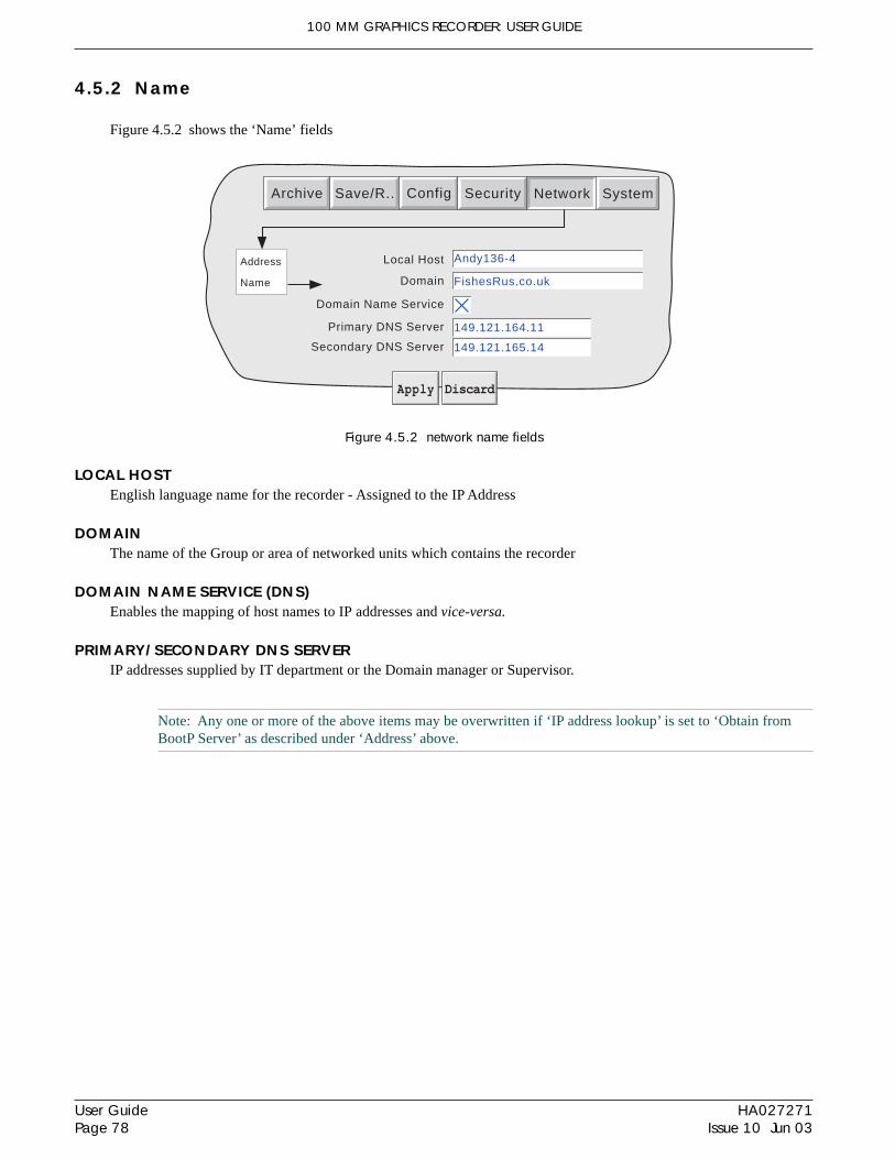
100 MM GRAPHICS RECORDER: USER GUIDE
HA027271Issue 10 Jun 03
User GuidePage 78
4.5.2 Name
Figure 4.5.2 shows the ‘Name’ fields
Figure 4.5.2 network name fields
LOCAL HOSTEnglish language name for the recorder - Assigned to the IP Address
DOMAINThe name of the Group or area of networked units which contains the recorder
DOMAIN NAME SERVICE (DNS)Enables the mapping of host names to IP addresses and vice-versa.
PRIMARY/SECONDARY DNS SERVERIP addresses supplied by IT department or the Domain manager or Supervisor.
Note: Any one or more of the above items may be overwritten if ‘IP address lookup’ is set to ‘Obtain fromBootP Server’ as described under ‘Address’ above.
Domain Name Service
Primary DNS Server
Secondary DNS Server
Local Host Andy136-4
149.121.164.11
149.121.165.14
Apply Discard
Domain FishesRus.co.uk
Address
Name
Archive SystemSave/R.. Config Security Network
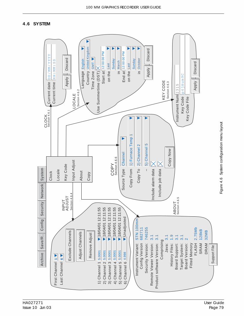
100 MM GRAPHICS RECORDER: USER GUIDE
User GuidePage 79
HA027271Issue 10 Jun 03
4.6 SYSTEM
Figu
re 4
.6 S
yste
m c
onfig
urat
ion
men
u la
yout
La
ng
ua
ge
En
glis
h
Ap
ply
Dis
card
Co
un
try
Un
ited
Kin
gd
om
Tim
e Z
on
eG
MT
Use
Su
mm
ert
ime
(D
ST
)S
tart
at
12
:00
:00
PM
on
th
e in
La
st
Su
nd
ay
Ma
rch
En
d a
t1
2:0
0:0
0 P
M
on
th
e in
La
st
Su
nd
ay
Oct
ob
er
LO
CA
LE
Se
ctio
n 4
.6.2
Fir
st C
ha
nn
el
1
La
st C
ha
nn
el
6 Ad
just
Ch
an
ne
ls
1)
Ch
an
ne
l 1
2)
Ch
an
ne
l 23
) C
ha
nn
el 3
4)
Ch
an
ne
l 45
.00
01
Re
mo
ve A
dju
st
Exc
lud
e C
ha
nn
els
5)
Ch
an
ne
l 56
) C
ha
nn
el 6
5.0
00
1
5.0
00
1
5.0
00
118
/04/
01 1
2:11
:55
5.0
00
1
4.9
98
18/0
4/01
12:
11:5
518
/04/
01 1
2:11
:55
18/0
4/01
12:
11:5
518
/04/
01 1
2:11
:55
Un
ad
just
ed
AB
OU
T
Java
:H
isto
ry F
iles:
Bo
ard
Su
pp
ort
:T
arg
et
Sys
tem
:
FL
AS
HS
RA
M2
.75
Mb
Pro
du
ct s
oft
wa
re V
ers
ion
:C
om
pri
sin
g
Fit
ted
Me
mo
ry
3.1
1.9
3.1
3.1
12
8kB
3.1
Bo
ard
Ve
rsio
n:
2
DR
AM
32
MB
Se
curi
ty V
ers
ion
:7
46
25
5C
on
fig
Ve
rsio
n6
82
71
1
Re
mo
te V
iew
er
Ve
rsio
n:
3.1
Inst
rum
en
t N
um
be
rK
ey
Co
de
2315
p4jHum9C
Ap
ply
Dis
card
Ke
y C
od
e F
ileKE
Y C
OD
E
CL
OC
KC
urr
en
t d
ate
Cu
rre
nt
tim
eDD/MM/YYYY
HH:MM:SS
Ap
ply
Dis
card
INP
UT
AD
JUS
T
Arc
hiv
eS
ave
/R..
Co
nfi
gS
ecu
rity
Ne
two
rk
Se
ctio
n 4
.6.4
Se
ctio
n 4
.6.5
Se
ctio
n 4
.6.1
Se
ctio
n 4
.6.3
Sup
port
File
Inst
rum
en
t V
ari
an
t:S
TN
10
0m
m
Co
py
No
w
So
urc
e T
ype
Co
py
Fro
m
Co
py
To –
Incl
ud
e a
larm
da
ta
Incl
ud
e jo
b d
ata
Ch
an
ne
l
1)
Fu
rna
ce T
em
p 1
2)
Ch
an
ne
l 2
5)
Ch
an
ne
l 5
CO
PY
Se
ctio
n 4
.6.6
Sys
tem
Clo
ck
Lo
cale
Ke
y C
od
e
Inp
ut
Ad
just
Ab
ou
t
Co
py
100 MM GRAPHICS RECORDER: USER GUIDE
HA027271Issue 10 Jun 03
User GuidePage 80
4.6 SYSTEM (Cont.)Touching the System key calls the pick list: Clock, Locale, Keycode, Input Adjust, About
Figure 4.6 above, shows an overview of the System Menus.
4.6.1 ClockSelecting 'clock' causes the recorder's date and time to be displayed. To edit the date, touch the current date area, tocall the keyboard and enter the new numbers. The date is edited in a similar way. The settings apply as soon as the'Apply settings' button is touched. See also SNTP details in section 4.5.1.
4.6.2 LocaleThis allows the setting of the following items:Language Choose the required language from the picklistCountry Displays a pick list of countries associated with the selected languageTime zone* Select GMT, UTC, ECT, EET, ART, EAT, MET, NET, PLT, IST, BST, VST, CTT, JST, ACT,
AET, SST, NST, MIT, HST, AST, PST, PNT, MST, CST, EST, IET, PRT, CNT, AGT, BET, CATfrom picklist.
Use Summertime (DST)*Select box if daylight saving is to be used, If 'Use Summertime (DST)' is selected, the times anddates for the start and end of summertime can be entered using picklists - see figure 4.6
Notes:1. Date format DD/MM/YY or MM/DD/YY is defined by the language and country selected. Time format
(e.g. 12/24 hr clock) is defined by the country selected.2. When using Remote Viewer, the host PC's locale information and the recorder locale information should
match, or the displayed time will not be correct.
*Note: For more information, see section B7 (Annex B), and/or http://www.timeanddate.com
4.6.3 Keycode
This is a means of allowing new options to be enabled, by the entering of a code, using standard text entry techniques,or by reading a file from a floppy disk. If a File is specified, the first line of the file must be the Key Code. To selectthe file for reading, the Key Code File field is touched, to display the file list - if necessary, refer to section 5, below,for more details
The Instrument Number, which must be quoted if ordering upgrades, is unique to the instrument and is not usereditable.
4.6.4 Input adjust
This facility allows the user to compensate for tolerance errors etc. The technique used is to select those channels towhich adjust is to be applied, then for each channel:a apply a known low level signal (at or close to the low input range value) to the relevant input. When the recorder
reading is steady, press 'Apply'.b. apply a known high level signal (at, or close to, the high input range value) to the relevant input. When the re-
corder reading is steady, press 'Apply'.
Note: Input adjust cannot be applied to input channels with input type of 'Digital', 'Test' or 'comms'.

100 MM GRAPHICS RECORDER: USER GUIDE
User GuidePage 81
HA027271Issue 10 Jun 03
4.6.4 INPUT ADJUST (Cont.)
Figure 4.6.4a shows the initial display which appears when 'Input adjust' is first selected from the SYSTEM menu.Channels 1 to 6 are selected by default.
Figure 4.6.4a Input adjust status page
First channel Allows the user to select the lowest channel number of all the channels to be adjusted.Last channel Allows the user to select the highest channel number of all the channels to be adjusted.Exclude Channels Presents a list of all the channels from the First channel to the Last channel inclusive, each of
which can be removed from the list by 'unchecking' its check box. The channels displayed inthe status page reflect this selection.
Adjust channels Initiates the adjustment procedure to all the channels from the First channel to the Last channelinclusive, unless the effectivity is modified using the Select Channels key.
Remove Adjust Returns the selected channels to factory calibration1) Channel 1 etc. A list of channels required to be susceptible to the adjustment procedure, together with their
current values and their adjustment status (i.e. Unadjusted or, the time/date of the previousadjustment (if any)).
1) Channel 1
2) Channel 23) Channel 3
4) Channel 45) Channel 56) Channel 6
Exclude Channels
First Channel 1 Select first channel for adjust
Last Channel 6 Select final channel for adjust
Adjust Channels Initiate adjust-ment procedure
1) Channel 1
2) Channel 23) Channel 3
4) Channel 4 5.0001
Remove Adjust
Exclude Channels
Remove previ-ous adjustments
5) Channel 56) Channel 6
5.0001
5.0001
5.0001 18/04/01 12:11:55
5.0001
4.998
18/04/01 12:11:5518/04/01 12:11:5518/04/01 12:11:5518/04/01 12:11:55Unadjusted
Clock
Locale
Key Code
Input Adjust
About
Remove/Addindividual channelsfrom adjustment list
Archive SystemSave/R.. Config Security Network
= included in list
Copy
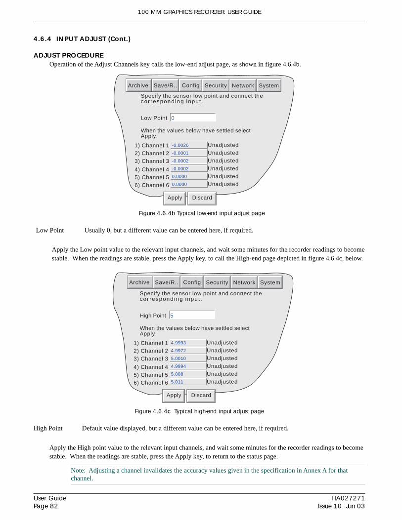
100 MM GRAPHICS RECORDER: USER GUIDE
HA027271Issue 10 Jun 03
User GuidePage 82
4.6.4 INPUT ADJUST (Cont.)
ADJUST PROCEDUREOperation of the Adjust Channels key calls the low-end adjust page, as shown in figure 4.6.4b.
Figure 4.6.4c Typical high-end input adjust page
High Point Default value displayed, but a different value can be entered here, if required.
Apply the High point value to the relevant input channels, and wait some minutes for the recorder readings to becomestable. When the readings are stable, press the Apply key, to return to the status page.
Note: Adjusting a channel invalidates the accuracy values given in the specification in Annex A for thatchannel.
Figure 4.6.4b Typical low-end input adjust page
Low Point Usually 0, but a different value can be entered here, if required.
Apply the Low point value to the relevant input channels, and wait some minutes for the recorder readings to becomestable. When the readings are stable, press the Apply key, to call the High-end page depicted in figure 4.6.4c, below.
Specify the sensor low point and connect thecor respond ing input .
2) Channel 23) Channel 3
4) Channel 4 -0.0002
5) Channel 56) Channel 6
-0.0002
-0.0001
-0.0026
0.0000
0.0000 Unadjusted
1) Channel 1
Low Point 0
When the values below have settled selectApply.
UnadjustedUnadjustedUnadjustedUnadjustedUnadjusted
Apply Discard
Archive SystemSave/R.. Config Security Network
Specify the sensor low point and connect thecor respond ing input .
2) Channel 23) Channel 3
4) Channel 4 4.9994
5) Channel 56) Channel 6
5.0010
4.9972
4.9993
5.008
5.011 Unadjusted
1) Channel 1
High Point 5
When the values below have settled selectApply.
UnadjustedUnadjustedUnadjustedUnadjustedUnadjusted
Apply Discard
Archive SystemSave/R.. Config Security Network

100 MM GRAPHICS RECORDER: USER GUIDE
User GuidePage 83
HA027271Issue 10 Jun 03
4.6.5 About
Selecting 'About' gives details of the version numbers of different aspects of the recorder, and details of the amount ofmemory fitted.
Java:History Files:
Board Support:Target System:
FLASHSRAM
2.75Mb
Product software Version:Comprising
Fitted Memory
3.11.93.13.1
128kB
3.1
Board Version: 2
DRAM 32MB
Security Version: 746255Config Version: 682711
Remote Viewer Version: 3.1
Support File
Clock
Locale
Key Code
Input Adjust
About
Appears only atremote viewer
Archive SystemSave/R.. Config Security Network
Copy
Instrument Variant: STN 100mm
Figure 4.6.5 Access to the 'About' display
INSTRUMENT VARIANTDisplays an instrument type code.
CONFIG VERSIONWhenever a change to the Configuration of the recorder is applied the 'Config version' is incremented. For these pur-poses, Configuration is defined as including all items within the menu structures of the Config and Network keys. Itdoes not include those items associated with the Security key. Config version is printed on the 'chart' at power up. Seealso the note below.
SECURITY VERSIONWhenever a change is made to an item within the Security menus, the Security version is incremented. Security ver-sion is printed on the 'chart' at power up.
Note: Config version and/or Security version can be used as inputs to maths channels. If such a channel isincluded in one or more groups, the version number can be determined for any time/date when Trend Historymode is invoked for the group(s) in question. See the Options Manual for maths option details.

100 MM GRAPHICS RECORDER: USER GUIDE
HA027271Issue 10 Jun 03
User GuidePage 84
4.6.5 ABOUT (Cont.)
SUPPORT FILE If the unit is not performing as it should (e.g. it resets itself unexpectedly), the Support File key allows the user tosave 'critical system files' into a single file (SupportInfo.uhq*) to the instrument's floppy disk/pc card, or to the remoteviewer's PC, for despatch to the manufacturer for analysis. For security reasons, this file cannot be viewed by anyoneother than the manufacturer or his agents.
Once the save operation is complete, a 'Support' message appears on the screen giving details of where to send thefile. More information is held in the file 'SupportInfo.txt' which is also saved to the disk. This file can be opened, andthe information within it read, by inserting the disk into a PC, clicking on the floppy disk icon (A drive) in 'My Com-puter' and then double clicking on the file icon when it appears.
* 'SupportInfo' is the default name. This name may be edited by the user before saving to disk or pc. The .uhq suffixis automatically appended to the new name.
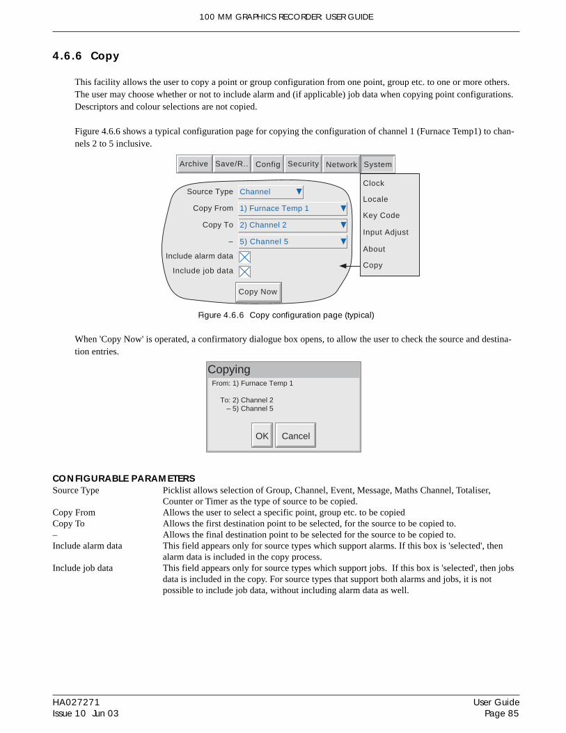
100 MM GRAPHICS RECORDER: USER GUIDE
User GuidePage 85
HA027271Issue 10 Jun 03
4.6.6 Copy
This facility allows the user to copy a point or group configuration from one point, group etc. to one or more others.The user may choose whether or not to include alarm and (if applicable) job data when copying point configurations.Descriptors and colour selections are not copied.
Figure 4.6.6 shows a typical configuration page for copying the configuration of channel 1 (Furnace Temp1) to chan-nels 2 to 5 inclusive.
Figure 4.6.6 Copy configuration page (typical)
When 'Copy Now' is operated, a confirmatory dialogue box opens, to allow the user to check the source and destina-tion entries.
Copy Now
Source Type
Copy From
Copy To
–
Include alarm data
Include job data
Channel
1) Furnace Temp 1
2) Channel 2
5) Channel 5
Clock
Locale
Key Code
Input Adjust
About
Archive SystemSave/R.. Config Security Network
Copy
CopyingFrom: 1) Furnace Temp 1
To: 2) Channel 2– 5) Channel 5
OK Cancel
CONFIGURABLE PARAMETERSSource Type Picklist allows selection of Group, Channel, Event, Message, Maths Channel, Totaliser,
Counter or Timer as the type of source to be copied.Copy From Allows the user to select a specific point, group etc. to be copiedCopy To Allows the first destination point to be selected, for the source to be copied to.– Allows the final destination point to be selected for the source to be copied to.Include alarm data This field appears only for source types which support alarms. If this box is 'selected', then
alarm data is included in the copy process.Include job data This field appears only for source types which support jobs. If this box is 'selected', then jobs
data is included in the copy. For source types that support both alarms and jobs, it is notpossible to include job data, without including alarm data as well.

100 MM GRAPHICS RECORDER: USER GUIDE
HA027271Issue 10 Jun 03
User GuidePage 86
4.6.6 COPY (Cont.)
Once the copy is complete, the user should enter the configuration area of the items that have been copied, and edit/apply the changes etc.
COPY RULES1. The first channel on any input card may not be a digital input type.2. If a destination channel was a digital input, AND the source channel is an analogue input AND 'include alarm
data' is not selected, the destination channel alarm settings will be set as:Enable = Off; Type = Absolute high; Threshold = 0.0; Dwell = 0.0.
3. If a destination channel was an analogue input, AND the source channel is a digital input AND 'include alarmdata' is not selected, the destination channel alarm settings will be set as:Enable = Off; Type = Digital; Threshold = Closed; Dwell = 0.0.
4. Descriptors and Colours are never copied.

100 MM GRAPHICS RECORDER: USER GUIDE
User GuidePage 87
HA027271Issue 10 Jun 03
4.7 JOBS
A number of sources (e.g. channel, event, totaliser) can be set up to trigger one or more jobs. The following descrip-tions include all possible job categories, but the jobs which are available on any particular recorder depend on theoptions fitted to that recorder.Many job categories require the relevant access level permission to be set, as describedin section 4.4.1, above.
The type of action (continuous or 'single-shot'), available for selection, depends on the type of trigger source. Con-tinuous actions are selected from: Whilst active, Whilst inactive or Whilst unacknowledged. The available single-shotactions are: On becoming active, On becoming inactive, On acknowledgement.
4.7.1 No Action
This means that no job action is configured for the trigger source.
4.7.2 Drive relay
If the Relay/Ethernet option is fitted, this means that the relay changes state when the trigger source becomes active.The relay is normally energised i.e. pin 2 (common) is shorted to pin 3 (normally open). When in alarm, the relay isde-energised i.e. pin 2 (common) is shorted to pin 1 (normally closed). Thus, if power is removed from the recorder,the relay automatically 'fails safe' to its alarm condition. See figure 2.2.1c for relay pinout.
4.7.3 Totaliser category
If the Totaliser option is fitted (section 4 of the Options manual), two totaliser jobs become available - Preset andDisable a selectable totaliser. 'Preset' loads the selected totaliser with the value set up in 'Preset' in the totaliser's con-figuration menu. Disable has the effect of stopping the totaliser accumulating.
Note: If more than one job is set up to disable a particular totaliser, then any of these jobs going active willdisable the totaliser, unless the software version is prior to version 1.7, in which case, all relevant jobs have tobe active simultaneously in order to disable the totaliser.
Job Number
ActionCategory
TotaliserOn
Totaliser 1
1
Totaliser
Preset
Active
Select Preset or Disable
Select Required Totaliser
Select Active or Inactive
Figure 4.7.3 Totaliser job menu layout

100 MM GRAPHICS RECORDER: USER GUIDE
HA027271Issue 10 Jun 03
User GuidePage 88
4.7.4 Message category
One or more messages (section 4.3.7), can be directed to the display (where it appears in a pop-up window), to bothgroups or to a specified group. Messages must be contiguous - e.g. messages 2, 3 and 4 may be sent, but messages 1,3 and 4 cannot be sent without message 2.
Figure 4.7.4 Message job menu layout
4.7.5 Maths Category
If the Maths option is fitted (section 3 of the Options Manual), the following jobs become available
Reset Sets the selected maths channel value to zero.Disable Stops historical functions such as Fvalue, Stopwatch and Rolling Average from accumulating further
values. When the function is subsequently re-enabled, the function re-starts from its pre-disabled value.'Disable' has no effect on other functions.
Switch to B Causes the relevant maths channel to copy source B instead of its normal source A - see section 3.1.4 ofthe Options manual for further details.
Trigger Used to initiate a 'Sample and hold' function - see section 3.1.4 of the Options manual for further details.
Job Number
Send Message(s) toCategory
GroupFirst Message
1) group 1
1
Message
Specified Group Select 'Display', 'All groups', or 'Specified Group'
Message 1
Last Message Message 12
Select Group (if 'Specified Group' selected above)
Select first message of message list
Select final message of message list
On Active Select Active or Inactive
Figure 4.7.5 Maths job menu layout
Job Number
ActionCategory
MathOn
Math 1
1
Math
Reset
Active
Select 'Reset', 'Disable''Switch to B' or 'Trigger'
Select Required Maths channel
Select 'Active', 'Inactive',or 'Acknowledgement'

100 MM GRAPHICS RECORDER: USER GUIDE
User GuidePage 89
HA027271Issue 10 Jun 03
4.7.6 Clock category
This job causes the System Clock to be Preset to the value entered in Instrument Configuration (Preset Hour, PresetMinute) (Section 4.3.1). This job can be used to synchronise a number of recorders as follows:a. For each recorder, set up one input channel as
Input Type........... DigitalClosed String ...... Synch (for example)Enable ................. TriggerActive when........ SynchJob 1 category .... ClockJob 1 action......... Preset.Job 1 On ............. Active
b. For each recorder, set the same preset hour and minute in Instrument Configuration.c. For each recorder provide a simultaneous pulse or contact closure to the digital input previously set up.
The recorders will all be automatically set to the preset time on receipt of the input.
An alternative way of synchronising resorders is via an FTP time server (SNTP) as described in section 4.5.1.
Job Number
ActionCategory
On Active
1
Clock
Preset Select 'Preset' or 'Disable'Select 'Active', 'Inactive'or 'Acknowledgement'
Figure 4.7.6 Clock job menu layout
Note: Whenever a time change occurs, a green line is drawn across the chart in vertical trend mode
4.7.7 Counter category
If the Counter option is fitted (section 5 of the Options Manual), the following jobs become available:1. Preset counter - loads the selected counter with the preset value set in the configuration for that counter.2. Disable counter - stops the selected counter.3. Increment adds 1 to the selected counter's value.4. Decrement subtracts 1 from the selected counter's value.
Figure 4.7.7 Counter job menu layout
Job Number
ActionCategory
CounterOn
Counter 1
1
Counter
Preset
Active
Select 'Preset', 'Disable', 'Increment' or 'Decrement'.
Select Required Counter
Select 'Active', 'Inactive' or 'Acknowledgement'

100 MM GRAPHICS RECORDER: USER GUIDE
HA027271Issue 10 Jun 03
User GuidePage 90
4.7.8 Timer jobs
If the Timer option is fitted (section 6 of the Options manual), the following jobs become available:1. Reset timer - sets the timer to zero2. Start timer - causes the timer to start.3. Disable timer - stops the timer.
Job Number
ActionCategory
TimerOn
Timer 1
1
Timer
Reset
Active
Select 'Reset', 'Start' or 'Disable'
Select Required Counter
Select 'Active', 'Inactive' or 'Acknowledgement'
Figure 4.7.9 Recording job menu layout
Job Number
RecordingCategory
GroupWhile
1) Group 1
1
Recording
Enable
Active
Select 'Enable' or 'Speed/Interval B'
Select Required Group
Select 'Active', 'Inactive' or 'Unacknowledged'
Figure 4.7.8 Timer job menu layout
4.7.9 Recording jobs
A Recording job:a) allows the user to record to a specified group's history file, only by job initiation.b) allows the recording speed/interval B to be selected for use, for the duration of the job. See 'Group configuration
for A/B switching details.
Notes:1 The group in question will be recorded only if Recording Enable selected in Group Configuration (sec-
tion 4.3.2) and the job is active.2. A blue line is drawn across the chart whenever a recoding job is used to disable/enable recording.

100 MM GRAPHICS RECORDER: USER GUIDE
User GuidePage 91
HA027271Issue 10 Jun 03
4.7.10 Trend jobs
Trend jobs allow the following actions to occur:
Span B Switches the point being configured to span B and zone B, for as long as the job is active.Span B Group Switches all the points in the selected group to their individual spans and zones B, for as long as
the job is active.Colour B Switches the point being configured to colour B, for as long as the job is active.Colour B Group Switches all the points in the selected group to their individual colours B, for as long as the job is
active.Speed/Interval B Switches Trend Speed/Interval for the selected group to Speed/Interval B, for as long as the job is
active.
Note: Default B values are the same as the initial default 'A' Values. Thus, if a 'B' value has not been set, thedefault 'A' value will be used.
Figure 4.7.10 Trend job menu layout
4..7.11 Alarm acknowledge jobs
This allows the user to set up a job to acknowledge alarms. 'All Alarms', 'Alarms on Group' or 'Alarms on Point' canbe selected. If Group or Point are selected, a further selection box allows a group or point, respectively, to be defined.
Job Number
ActionCategory
GroupWhile
1) Group 1
1
Trend
Speed/Interval B
Active
Select required 'switch to B' item
Select Required Group or Point (according to action)
Select 'Active', 'Inactive' or 'Unacknowledged'
Figure 4.7.11 Alarm acknowledge job menu layout
Job Number
ActionCategory
On
1
Alarm Acknowledge
Alarms on Group
Active
Group 1) Group 1
Select 'Active', 'Inactive'or 'Acknowledgement'
Select 'All', 'Group' or 'Point' alarms
Select Required Group/Point
100 MM GRAPHICS RECORDER: USER GUIDE
HA027271Issue 10 Jun 03
User GuidePage 92
5 FILE
Figure 5, below, gives an overview of the File Menus. The area is entered by touching the 'File' key of the root menu,and can be used to display the contents of directories stored both in the user area of flash memory and on any diskcurrently inserted.
The first display page shows the 'volume' or 'device' names associated with the various areas of memory available tothe user. If one of these volume names is selected (touched), and the 'open-folder' key operated, the contents of theselected volume is displayed. This would typically consist of a list of folders. Similarly, if a folder name is selectedand the 'open folder' key is touched, the contents of the folder is displayed and so on.
To return to higher levels, the 'close-folder' key is used.
The path name of the current window is shown at the top of the window.
5.1 FILER OPTION MENU KEYS
These keys appear in a pop-up menu when the root menu Options key is pressed. The pop-up menu appears onlywhen an actual file has been selected (i.e. it does not appear if a directory (folder) or volume is selected.) Cut andpaste functions are available only to users with the relevant access permissions (section 4.4).
Cut Removes a file from the list, ready for 'pasting' to another destination.Copy Copies a file from the list, ready for 'pasting' to another destination.Delete Removes a file from the memory.New Allows a new directory (folder) to be createdPaste Places a 'cut' or 'copy' file into the new destination.Refresh Refreshes the display.
A key's legend is hidden (displayed in white) if at any time its function is not applicable.
5.2 THE HIDE KEY
The Hide key at the top right corner of the display screen is used to hide (show) Type, Date and Bytes information,allowing the full file name text string to appear.

100 MM GRAPHICS RECORDER: USER GUIDE
User GuidePage 93
HA027271Issue 10 Jun 03
5 FILE (Cont.)
Figure 5 File system overview
Hide
New Delete
Cut Copy
Paste Refresh
Filer Options
99%
3
5
Select filename
6
Select folder
Call Fileroptions menu
EngineerEngineer
14:20:3503/01/01
\
Name Type
\Floppy\ Remov..
Closefolder
Openfolder
1
Selectvolume
Hide99%Engineer
14:20:3503/01/01
\user\
Name Type Date
errorlog5 Text 23/09/00 17:48:40 1186
errorlog4 Text 23/09/00 17;47:20 1205
errorlog3 Text 23/09/00 17:46:52 1205
errorlog2 Text 1205errorlog1 Text 01/01/01 00:02:36 1205
errorlog Text 03/01/01 11:29:26 24730
config Text 02/01/01 10:48:58 13220config Config 02/12/00 12:20:46 3071
Bytes
01/01/00 00:04:20
screen\ Folder 12/12/00 14:46:32
Hide99%Engineer
14:20:3503/01/01
\user\history\
Name Typegroup-one,,80.. History
Date Bytes02/01/01 16:27:26 936
group-one,,80.. History 02/01/01 16:28:50 959
group-one,,80.. History 02/01/01 16:33:04 932
group-one,,80.. History 02/01/01 16:33:10 861
group-one,,80.. History 02/01/01 16:34:50 911group-one,,80.. History 02/01/01 17:19:00 4131
group-one,,80.. History 03/01/01 11:38:30 14612
group-one,,80.. History 03/01/01 11:41:40 1210group-one,,80.. History 03/01/01 15:00:00 27622
\user\ Flash
Hide key
history\ Folder
4
group-one,,80.. History 02/01/01 16:32:02 1055
2Options
Goto Group
Operator
Login
Cycle
Home
File
Root menu
Options
Goto Group
Operator
Login
Cycle
Home
File
Root menu

100 MM GRAPHICS RECORDER: USER GUIDE
HA027271Issue 10 Jun 03
User GuidePage 94
5.3 FILE STRUCTURE
5.3.1 Software versions prior to 3.1
The file structure on the floppy disk or pc card, is as depicted below in figure 5.3.1. The History folder contains onefolder for each group fitted. Each Group folder contains all the history files for that group. Figure 5.3.1 illustratesthis for a 2-group unit.
Figure 5.3.2 File structure for software versions 3.1 onwards
The subfolder names are the numerical part of the first history file that they contain. For example if the first file nameis Furnace1 Temp~80155F2601000120.uhh, then the subdirectory name will be 80155F2601000120. If there aremore than 32 files, the next subdirectory name is 80155F2601000140* (assuming the file names are contiguous).
* 20 in hex = 32 in decimal
Figure 5.3.1 File structure for software versions prior to 3.1
5.3.2 Software versions 3.1 onwards
The file structure for versions 3.1 onwards is similar except in that an extra level of subdirectories has been addedwithin the group folders. Each subdirectory contains a maximum of 32 files, there being sufficient subdirectoriescreated, to contain all the group's history files. This is illustrated in figure 5.3.2 below.
FloppyDisk
history\
group 2 group 1
All group 2history
files
All group 1history
files
First 32group 1history
files
subfolder1
subfoldern
subfolder2
Second 32group 1history
files
Remaininggroup 1history
files(max = 32)
FloppyDisk
history\
group 2 group 1
Only group 1 structureshown, for clarity.
Each group containssubfolders.Each subfolder cancontain up to 32 files.

100 MM GRAPHICS RECORDER: USER GUIDE
User GuidePage 95
HA027271Issue 10 Jun 03
ANNEX A: SPECIFICATION
INSTALLATION CATEGORY AND POLLUTION DEGREE
This product has been designed to conform to BS EN61010 installation category II and pollution degree 2. These aredefined as follows:
Installation category IIThe rated impulse voltage for equipment on nominal 230V ac mains is 2500V.
Pollution degree 2Normally, only non-conductive pollution occurs. Occasionally, however, a temporary conductivity caused by conden-sation shall be expected.
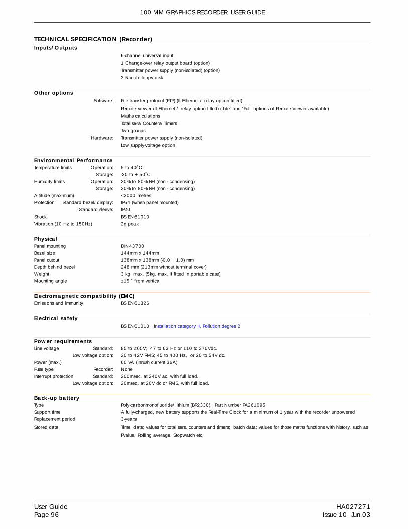
100 MM GRAPHICS RECORDER: USER GUIDE
HA027271Issue 10 Jun 03
User GuidePage 96
TECHNICAL SPECIFICATION (Recorder) Inputs/Outputs
6-channel universal input
1 Change-over relay output board (option)Transmitter power supply (non-isolated) (option)3.5 inch floppy disk
Other optionsSoftware: File transfer protocol (FTP) (If Ethernet / relay option fitted)
Remote viewer (If Ethernet / relay option fitted) ('Lite' and 'Full' options of Remote Viewer available)Maths calculationsTotalisers/Counters/TimersTwo groups
Hardware: Transmitter power supply (non-isolated)Low supply-voltage option
Environmental PerformanceTemperature limits Operation: 5 to 40˚C
Storage: -20 to + 50˚CHumidity limits Operation: 20% to 80% RH (non - condensing)
Storage: 20% to 80% RH (non - condensing)Altitude (maximum) <2000 metresProtection Standard bezel/display: IP54 (when panel mounted)
Standard sleeve: IP20Shock BS EN61010Vibration (10 Hz to 150Hz) 2g peak
PhysicalPanel mounting DIN43700Bezel size 144mm x 144mmPanel cutout 138mm x 138mm (-0.0 + 1.0) mmDepth behind bezel 248 mm (213mm without terminal cover)Weight 3 kg. max. (5kg. max. if fitted in portable case)Mounting angle ±15 ˚ from vertical
Electromagnetic compatibility (EMC)Emissions and immunity BS EN61326
Electrical safetyBS EN61010. Installation category II, Pollution degree 2
Power requirementsLine voltage Standard: 85 to 265V; 47 to 63 Hz or 110 to 370Vdc.
Low voltage option: 20 to 42V RMS; 45 to 400 Hz, or 20 to 54V dc.Power (max.) 60 VA (Inrush current 36A)Fuse type Recorder: NoneInterrupt protection Standard: 200msec. at 240V ac, with full load.
Low voltage option: 20msec. at 20V dc or RMS, with full load.
Back-up batteryType Poly-carbonmonofluoride/lithium (BR2330). Part Number PA261095Support time A fully-charged, new battery supports the Real-Time Clock for a minimum of 1 year with the recorder unpoweredReplacement period 3-years
Stored data Time; date; values for totalisers, counters and timers; batch data; values for those maths functions with history, such as
Fvalue, Rolling average, Stopwatch etc.

100 MM GRAPHICS RECORDER: USER GUIDE
User GuidePage 97
HA027271Issue 10 Jun 03
TECHNICAL SPECIFICATION (RECORDER) (Cont.)
Operator interfaceColour STN LCD with cold cathode backlighting, fitted with resistive, analogue touch panel.Screen specification 1/4 VGA Resolution = 320 x 240 pixels
Update/archive rates Input/relay output sample rate: 8 Hz.
Display update: 1 Hz,Archive sample value: Latest value at archive time
Trended/displayed value: Latest value at display update time.
Transmitter power supply (non-isolated)Output voltage 24 Volts ± 10%.
Maximum current Continuous: 120 mA (total for all outputs).
Peak: 240 mA (total for all outputs).
Isolation (dc to 65Hz; BS EN61010) Installation category II; Pollution degree 2
Non isolated. 0 V returns are connected to chassis ground.

100 MM GRAPHICS RECORDER: USER GUIDE
HA027271Issue 10 Jun 03
User GuidePage 98
TECHNICAL SPECIFICATION (Universal inputs)
General*Termination Inputs: 22 - way Edge connector/terminal block
Max. number of inputs six
Input ranges -38 mV to +38mV; -150 mV to +150mV; -1 Volt to +1Volt; -10 Volts to + 10Volts
Input types Dc volts, dc millivolts, dc milliamps, (with external shunt), thermocouple, 2/3 wire resistance temperature detector
(RTD), Ohms, Contact closure (not channel 1) (Minimum contact closure = 60msec.)
Input type mix Freely configurable
Sample rate See 'Update information' above
Noise rejection (48 to 62Hz)
Common mode: >140dB (Channel to channel and channel to ground)
Series mode: >60dB
Maximum common mode voltage 250Volts continuous
Maximum series mode voltage 45mV at lowest range; 12Volts peak at highest range
Isolation (dc to 65Hz; BS EN61010) Installation category II; Pollution degree 2
300V RMS or dc channel to channel (double insulation), channel to common electronics (double insulation) and
channel to ground (basic insulation)
Dielectric strength Channel to ground: 1350Vac for 1 minute.
Channel to channel: 2300Vac for 1 minute
Insulation resistance >10MΩ at 500V dc
Input impedance 10V range: 68.8kΩ
Other ranges: >10MΩ
Overvoltage protection 50V peak (150V with attenuator)
Open circuit detection ± 57nA max
Recognition time: 500mSec
Minimum break resistance: 10MΩ
DC input rangesShunt Externally mounted resistor modules
Additional error due to shunt 0.1% of input
Performance See table
Low High Maximum error Worst case temperatureRange Range (Instrument at 20 C) performance-38 mV 38 mV 1.4 V 0.085% input + 0.051% range 80ppm of input per deg C
-150 mV 150 mV 5.5 V 0.084% input + 0.038% range 80ppm of input per deg C-1 V 1 V 37 V 0.084% input + 0.029% range 80ppm of input per deg C
-10 V 10 V 370 V 0.275% input + 0.030% range 272ppm of input per deg C
Resolution

100 MM GRAPHICS RECORDER: USER GUIDE
User GuidePage 99
HA027271Issue 10 Jun 03
TECHNICAL SPECIFICATION (Universal inputs) (Cont.)
Resistance inputsTemperature scale ITS90
Types, ranges and accuracies See tables (values exclude influence of lead resistance)
Influence of lead resistance Error: Negligible
Mismatch: 1Ω/Ω
LowRange
0Ω0Ω0Ω 6kΩ 148mΩ 35ppm of input per deg C0.035% input + 0.035% range
HighRange
150Ω600Ω
Resolu-tion
5mΩ22mΩ
Maximum error(Instrument at 20 C)
0.035% input + 0.110% range 35ppm of input per deg C
35ppm of input per deg C0.035% input + 0.065% range
Worst case temperatureperformance
Thermocouple dataTemperature scale ITS90
Bias current 0.05nA
Cold junction types Off, internal, external, remote.
Remote CJ source: Any input or maths channel
Internal CJ error 1˚C max with instrument at 25˚C
Internal CJ rejection ratio 50:1 minimum
Upscale/downscale drive Types: 'High'. 'low' or 'none' selectable for each thermocouple channel.
Additional error: Typically 0.01˚C - depends on wiring. (Detect current = 57nA.)
Types, ranges and accuracies See table
RTD typeCu10
JPT100Ni100
Ni120
Overall range ( C) Standard0.02 C
0.01 C
0.01 C
0.01 C
0.01 C
0.09 C0.01 C
Pt100
Pt100APt1000
-20 to + 400
-220 to + 630
-60 to + 250
-50 to + 170-200 to + 850
-200 to + 600-200 to + 850
General Electric Co.
JIS C1604:1989
DIN43760:1987
DIN43760:1987
IEC751
Eurotherm Recorders SAIEC751
Max. linearisation error
Cu53 < 0.01 C-70 to + 200 RC21-4-1966
0.14 C
0.07 C
0 to 400 C = 1.7 C
Max.linearisation error
0.12 C
0.08 C
0.03 C
0.07 C
0.02 C
0.04 C
0.04 C
0.04 C
0.02 C
0.08 C
0.06 C
0.02 C
400 to 1820 C = 0.03 C
0.02 C
0.04 C
Ni/NiMo
Pt20%Rh/Pt40%Rh
T/C type
B
C
D
E
G2
J
K
R
S
T
U
NiMo/NiCo
Platinel
L
N
0 to + 1406
0 to + 1888
0 to + 1820
0 to + 2300
0 to + 2495
-270 to + 10000 to + 2315
-210 to + 1200-270 to + 1372
-50 to + 1768
-50 to + 1768
-270 to + 400
-200 to + 600
-50 to + 1410
0 to + 1370
-200 to + 900
-270 to + 1300
Overall range ( C)
Ipsen
ASTM E1751-95
IEC584.1
Standard
Hoskins
Hoskins
IEC584.1
Hoskins
IEC584.1
IEC584.1
IEC584.1
IEC584.1
IEC584.1
DIN43710:1985
ASTM E1751-95
Engelhard
DIN43710:1985 (To IPTS68)
IEC584.1

100 MM GRAPHICS RECORDER: USER GUIDE
HA027271Issue 10 Jun 03
User GuidePage 100
TECHNICAL SPECIFICATION (Ethernet/Relay output board option)
Network CommunicationsType IEEE802.3 10BaseTCable Type: CAT5
Maximum length: 100 metres
Termination: RJ45 telephone connector
Transport protocol TCP I/P, FTP
RelayGENERAL
Number of relays per board One
Maximum number of relay boards One
Type Single pole changeover (form C)
Termination Three-way connector
Estimated mechanical life of relay 30,000,000 operations
Update rate See 'Update/archive rates' in 'Universal inputs specification' above
AC load ratingsDerating
The figures given below are for resistive loads. For reactive or inductive loads, de-rate in accordance with graph 1, in which
F1 = Actually measured results on representative samples
F2 = Typical values (according to experience)
Contact life = Resistive contact life x reduction factor.
Maximum switching power 500VA
Maximum contact voltage 250V providing this does not cause the maximum switching power to be exceeded
Maximum contact current 2 Amps providing this does not cause the maximum switching power to be exceeded
DC load ratingsMaximum switching power See graph 2 for operating volt/Amp envelope
Maximum contact voltage/current See graph 2 for examples.
Safety isolationIsolation (dc to 65 Hz; BS EN61010) Installation category II; Pollution degree 2
Relay to relay: 300V RMS or dc (double insulation)
Relay to ground: 300V RMS or dc (basic insulation)
F1
F2
1 0.8 0.6 0.4 0.20.3
0.4
0.5
0.6
0.7
0.80.9
1F
Red
uctio
n F
acto
r F
Power factor (cos φ)
Graph 1 Derating curves for ac loads Graph 2 DC load switching curves
10
20
304050
100
200
300
0.1 0.2 0.5 5 20
Max. DC load breaking capacity
1 2
inductive load(L/R = 20msec)
resistive load
DC
Vol
tage
(V
olts
)
DC current (Amps)
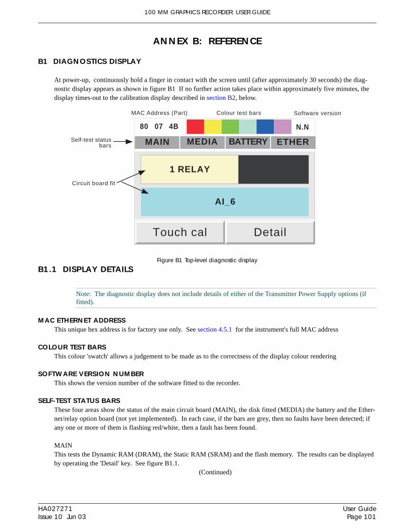
100 MM GRAPHICS RECORDER: USER GUIDE
User GuidePage 101
HA027271Issue 10 Jun 03
ANNEX B: REFERENCE
B1 DIAGNOSTICS DISPLAY
At power-up, continuously hold a finger in contact with the screen until (after approximately 30 seconds) the diag-nostic display appears as shown in figure B1 If no further action takes place within approximately five minutes, thedisplay times-out to the calibration display described in section B2, below.
Figure B1 Top-level diagnostic display
B1.1 DISPLAY DETAILS
Note: The diagnostic display does not include details of either of the Transmitter Power Supply options (iffitted).
MAC ETHERNET ADDRESSThis unique hex address is for factory use only. See section 4.5.1 for the instrument's full MAC address
COLOUR TEST BARSThis colour 'swatch' allows a judgement to be made as to the correctness of the display colour rendering
SOFTWARE VERSION NUMBERThis shows the version number of the software fitted to the recorder.
SELF-TEST STATUS BARSThese four areas show the status of the main circuit board (MAIN), the disk fitted (MEDIA) the battery and the Ether-net/relay option board (not yet implemented). In each case, if the bars are grey, then no faults have been detected; ifany one or more of them is flashing red/white, then a fault has been found.
MAINThis tests the Dynamic RAM (DRAM), the Static RAM (SRAM) and the flash memory. The results can be displayedby operating the 'Detail' key. See figure B1.1.
(Continued)
80
MAIN MEDIA BATTERY ETHER
Touch cal
07 4B N.N
AI_6
Detail
1 RELAY
MAC Address (Part) Colour test bars Software version
Self-test statusbars
Circuit board fit

100 MM GRAPHICS RECORDER: USER GUIDE
HA027271Issue 10 Jun 03
User GuidePage 102
SELF-TEST STATUS BARS (Cont.)
MEDIAThis sends a message to the disk, and then tries to read it back. Failure to succeed might be any one or more of thefollowing:1. No disk was fitted when the test was initiated.2. The disk is unformatted or incorrectly formatted.3. The disk is too full (less than 1kB remaining) for the message to be written to it.
BATTERYThis area flashes when the battery needs to be replaced (section B3). The test is performed once every 15 minutes.
ETHERNot applicable to this release.
CIRCUIT BOARDS FITTEDThe major part of the display screen is taken up with a representation of the rear of the recorder, showing what inputand output cards are fitted in each circuit board slot. 1_Relay represents the Ethernet/Relay output board; AI_6 repre-sents the six analogue inputs on the main board.
TOUCH CALThis key initiates the display calibration (offset correction) procedure, described in section B2 below.
DETAILTouching this key causes the main board test results to be displayed, as shown in figure B1.1 below.
To quit diagnostics, switch the recorder off, then, after a few seconds, switch it back on again
Figure B1.1 Main board self-test results display
MAIN BOARD TEST
DRAM: PASS
SRAM: PASS
FLASH: PASS
Done
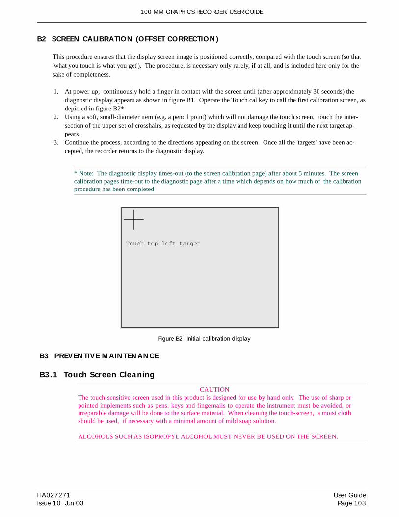
100 MM GRAPHICS RECORDER: USER GUIDE
User GuidePage 103
HA027271Issue 10 Jun 03
B2 SCREEN CALIBRATION (OFFSET CORRECTION)
This procedure ensures that the display screen image is positioned correctly, compared with the touch screen (so that'what you touch is what you get'). The procedure, is necessary only rarely, if at all, and is included here only for thesake of completeness.
1. At power-up, continuously hold a finger in contact with the screen until (after approximately 30 seconds) thediagnostic display appears as shown in figure B1. Operate the Touch cal key to call the first calibration screen, asdepicted in figure B2*
2. Using a soft, small-diameter item (e.g. a pencil point) which will not damage the touch screen, touch the inter-section of the upper set of crosshairs, as requested by the display and keep touching it until the next target ap-pears..
3. Continue the process, according to the directions appearing on the screen. Once all the 'targets' have been ac-cepted, the recorder returns to the diagnostic display.
* Note: The diagnostic display times-out (to the screen calibration page) after about 5 minutes. The screencalibration pages time-out to the diagnostic page after a time which depends on how much of the calibrationprocedure has been completed
Figure B2 Initial calibration display
B3 PREVENTIVE MAINTENANCE
B3.1 Touch Screen Cleaning
CAUTIONThe touch-sensitive screen used in this product is designed for use by hand only. The use of sharp orpointed implements such as pens, keys and fingernails to operate the instrument must be avoided, orirreparable damage will be done to the surface material. When cleaning the touch-screen, a moist clothshould be used, if necessary with a minimal amount of mild soap solution.
ALCOHOLS SUCH AS ISOPROPYL ALCOHOL MUST NEVER BE USED ON THE SCREEN.
Touch top left target

100 MM GRAPHICS RECORDER: USER GUIDE
HA027271Issue 10 Jun 03
User GuidePage 104
B3.2 Maintenance schedule
Battery replacement - Every three years
B3.3 Battery replacement procedure
Notes:1. The battery is of poly-carbonmonofluoride/lithium construction and should be disposed of accord-
ing to local regulations covering this type of battery.2. It is recommended that the recorder be isolated from mains (line) power before the battery is re-
placed. All battery backed RAM data is lost during battery change.
1. Remove the mains connector. For convenience, disconnect the relay and Ethernet connectors (if fitted).2. Remove the rear terminal cover (A) by pressing down on the catch and lifting off. Remove the input connector
(B), by pressing-in on the end clips and pulling on the connector (figure B3.2a).3. Remove the three screws 'C' in figure B3.2b.4. Carefully lift the front of the recorder case cover, and disconnect the two looms connecting it to the internal cir-
cuit board (figure B3.2c)5. Push the battery out of its holder as shown in figure B3.2d.6. Instal the new battery by pushing it into position (+ uppermost).7. Re-connect the two looms previously disconnected, then re-assemble the recorder.
Figure B3.2a Remove terminal cover and connectorFigure B3.2b Release cover plate
Figure B3.2c Disconnect looms; Remove cover plate
Figure B3.2d Replace battery
C
C
C
B A
Battery type: BR2330Part Number: PA261095
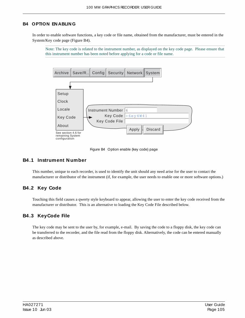
100 MM GRAPHICS RECORDER: USER GUIDE
User GuidePage 105
HA027271Issue 10 Jun 03
B4 OPTION ENABLING
In order to enable software functions, a key code or file name, obtained from the manufacturer, must be entered in theSystem/Key code page (Figure B4).
Note: The key code is related to the instrument number, as displayed on the key code page. Please ensure thatthis instrument number has been noted before applying for a code or file name.
Figure B4 Option enable (key code) page
B4.1 Instrument Number
This number, unique to each recorder, is used to identify the unit should any need arise for the user to contact themanufacturer or distributor of the instrument (if, for example, the user needs to enable one or more software options.)
B4.2 Key Code
Touching this field causes a qwerty style keyboard to appear, allowing the user to enter the key code received from themanufacturer or distributor. This is an alternative to loading the Key Code File described below.
B4.3 KeyCode File
The key code may be sent to the user by, for example, e-mail. By saving the code to a floppy disk, the key code canbe transferred to the recorder, and the file read from the floppy disk. Alternatively, the code can be entered manuallyas described above.
Instrument NumberKey Code
6
>6ey4W41
Apply Discard
Key Code File
Setup
Clock
Locale
Key Code
About
See section 4.6 forremaining Systemconfiguration
Archive SystemSave/R.. Config Security Network

100 MM GRAPHICS RECORDER: USER GUIDE
HA027271Issue 10 Jun 03
User GuidePage 106
B5 COLOUR SELECTION
The following table, gives RGB values and decimal and hex numbers for the available channel colours. Normally,this table is necessary only when communicating over the MOBUS link.
Note: Colour representation varies from screen to screen. For this reason, it is unlikely that the colour on aPC will match those on these pages or those on the recorder display.
Table B1, sheet 1: Colour definitions 0 to 27
Colour Red Green Blue Decimal Hex
Red 255 0 0 0 00
Blue 0 0 255 1 01
Green 0 255 0 2 02
Honey 255 191 0 3 03
Violet 170 321 153 4 04
Russet 170 95 0 5 05
Dark Blue 0 0 102 6 06
Jade 0 95 0 7 07
Magenta 255 0 102 8 08
Dusky Rose 255 95 51 9 09
Yellow 255 255 255 10 0A
Powder Blue 85 63 255 11 0B
Dark Red 170 0 0 12 0C
Avocado 0 233 102 13 0D
Indigo 85 0 102 14 0E
Dark Brown 85 63 0 15 0F
Ægean 0 63 51 16 10
Cyan 0 255 255 17 11
Aubergine 85 0 51 18 12
Dark Orange 255 63 0 19 13
Pale Yellow 255 255 51 20 14
Hyacinth 170 0 51 21 15
Dark Green 0 63 0 22 16
Sugar Pink 255 31 204 23 17
Bluebell 85 31 255 24 18
Orange 255 95 0 25 19
Pink 255 159 255 26 1A
Buttermilk 255 255 102 27 1B

100 MM GRAPHICS RECORDER: USER GUIDE
User GuidePage 107
HA027271Issue 10 Jun 03
B5 COLOUR SELECTION (Cont.)
Table B1, sheet 2: Colour definitions 28 to 55
Colour Red Green Blue Decimal Hex
Terracotta 170 63 0 28 1C
Blue Babe 85 95 255 29 1D
Lime 0 223 0 30 1E
Blue Jive 85 31 204 31 1F
Cucumber 0 255 153 32 20
EuroGreen 67 107 103 33 21
Wheatgerm 255 223 51 34 22
Sea Blue 85 159 255 35 23
Ginger 255 159 0 36 24
Aqua Pool 0 63 255 37 25
Pale Red 255 63 51 38 26
Pale Blue 85 127 255 39 27
Lilac 170 0 255 40 28
Sky Blue 85 191 255 41 29
Wild Moss 0 127 0 42 2A
Turquoise 0 127 153 43 2B
Pale Green 85 255 153 44 2C
Coffee 170 127 0 45 2D
Wicker 255 255 191 46 2E
Black 0 0 0 47 2F
Dark Dark Grey 48 48 48 48 30
Dark Grey 64 64 64 49 31
Grey 128 128 128 50 32
Light Light Dark Grey 154 154 154 51 33
Light Dark Grey 172 172 172 52 34
Light Grey 192 192 192 53 35
Light Light Grey 212 212 212 54 36
White 255 255 255 55 37

100 MM GRAPHICS RECORDER: USER GUIDE
HA027271Issue 10 Jun 03
User GuidePage 108
B6 TCP PORT NUMBERS
The following TCP ports are made use of by the recorder. (This information would be needed by anyone involved insetting up 'firewalls', which may be used selectively to block incoming or outgoing access to specific ports.)
PORT Usage
20 File Transfer Protocol - data
21 File Transfer Protocol - control
123 SNTP Serverv
502 Modbus/TCPIP communications
1264 Remote Viewer communications - general
50010 Remote Viewer communications - trend review
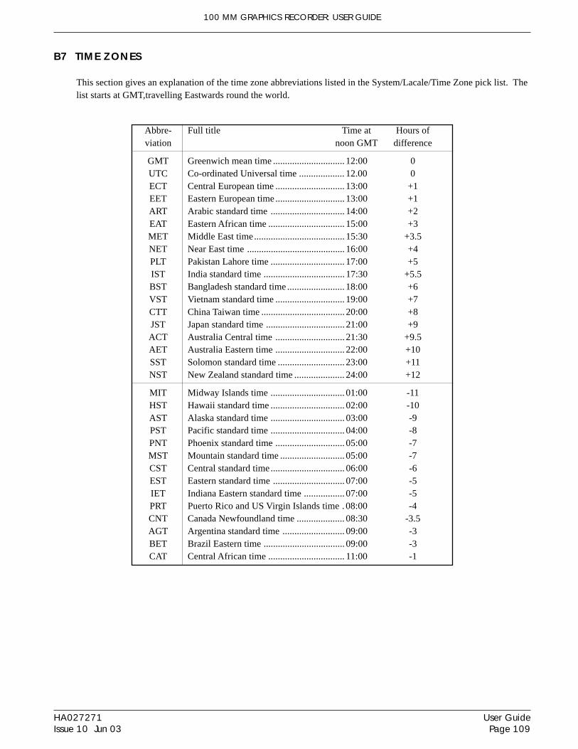
100 MM GRAPHICS RECORDER: USER GUIDE
User GuidePage 109
HA027271Issue 10 Jun 03
Abbre- Full title Time at Hours ofviation noon GMT difference
GMT Greenwich mean time .............................. 12:00 0UTC Co-ordinated Universal time ................... 12.00 0ECT Central European time ............................. 13:00 +1EET Eastern European time............................. 13:00 +1ART Arabic standard time ............................... 14:00 +2EAT Eastern African time ................................ 15:00 +3MET Middle East time...................................... 15:30 +3.5NET Near East time ......................................... 16:00 +4PLT Pakistan Lahore time ............................... 17:00 +5IST India standard time .................................. 17:30 +5.5BST Bangladesh standard time ........................ 18:00 +6VST Vietnam standard time ............................. 19:00 +7CTT China Taiwan time ................................... 20:00 +8JST Japan standard time ................................. 21:00 +9ACT Australia Central time ............................. 21:30 +9.5AET Australia Eastern time ............................. 22:00 +10SST Solomon standard time ............................ 23:00 +11NST New Zealand standard time ..................... 24:00 +12
MIT Midway Islands time ............................... 01:00 -11HST Hawaii standard time ............................... 02:00 -10AST Alaska standard time ............................... 03:00 -9PST Pacific standard time ............................... 04:00 -8PNT Phoenix standard time ............................. 05:00 -7MST Mountain standard time ........................... 05:00 -7CST Central standard time............................... 06:00 -6EST Eastern standard time .............................. 07:00 -5IET Indiana Eastern standard time ................. 07:00 -5PRT Puerto Rico and US Virgin Islands time .08:00 -4CNT Canada Newfoundland time .................... 08:30 -3.5AGT Argentina standard time .......................... 09:00 -3BET Brazil Eastern time .................................. 09:00 -3CAT Central African time ................................ 11:00 -1
B7 TIME ZONES
This section gives an explanation of the time zone abbreviations listed in the System/Lacale/Time Zone pick list. Thelist starts at GMT,travelling Eastwards round the world.

100 MM GRAPHICS RECORDER: USER GUIDE
HA027271Issue 10 Jun 03
User GuidePage 110
This page is deliberately left blank

100 MM GRAPHICS RECORDER: USER GUIDE
User GuidePage 111
HA027271Issue 10 Jun 03
Figure B8a Menu structure sheet 1 (Root Menu)
B8 MENU STRUCTURE
Engineer Group Name 11:19:3002/01/01
99%
1 (1) Water temp 1a 60.0000 68.5277 C
2 (1) Water temp 1b 30.0000 23.4531 C
2 (2) Water temp 1b 10.0000 15.7773 C
3 (1) 0il pressure 250.0000 260.3425PSI4 (1) Transfer 15.3678
Alarm Summary
Engineer Group Name 10:39:3802/01/01
99%
100.000.00
Channel 1 14.59 C
100.000.00
Channel 2 36.02 C
100.000.00
Channel 3 38.37 C
100.000.00
Channel 4 69.90 C
100.000.00
Channel 5 32.04 C
100.000.00
Channel 6 88.27 C
Group Name 12:03:2721/02/01
Channel 1 21.2613 C
0.000
35.00
Engineer
12:00:5221/02/01
12:02:1221/02/01
21/02/01 12:02:20 Alarm(s) off 2 (1)
99%
Ack AlarmConfirm acknowledge of alarm?
NoYes
Touch alarm to call 'Acknowledge'
dialogue box.
Appears only if permissionset in Security\Accessmenu for the user.
Engineer Group Name09:36:4202/01/01
100.00
0.00
100.00
0.00
100.00
0.00
100.00
0.00
100.00
0.00
100.00
0.00
99%
Engineer Group Name 15:01:4721/12/00
Channel 1 21.2613 C
35.00000.0000
21/12/00 14:43:37 Alarm(s) off 2 (1)
14:40:1721/12/00
14:53:3721/12/00
21/12/00 14:41:39 Alarm(s) on 2 (1)
99%
Engineer Group Name 11:19:3002/01/01
Channel 1
12.21 C
Channel 2
23.32 C
Channel 3
34.43 C
Channel 4
45.54 C
99%
Section 5
Hide
New Delete
Cut Copy
Paste Refresh
Filer Options
99%
3
5
6
Engineer
14:20:3503/01/01
\
Name Type
\Floppy\ Remov..
1
Hide99%Engineer
14:20:3503/01/01
\user\
Name Type Date
errorlog5 Text 23/09/00 17:48:40 1186
errorlog4 Text 23/09/00 17;47:20 1205
errorlog3 Text 23/09/00 17:46:52 1205
errorlog2 Text 1205errorlog1 Text 01/01/01 00:02:36 1205
errorlog Text 03/01/01 11:29:26 24730
config Text 02/01/01 10:48:58 13220config Config 02/12/00 12:20:46 3071
Bytes
01/01/00 00:04:20
screen\ Folder 12/12/00 14:46:32
Hide99%Engineer
14:20:3503/01/01
\user\history\
Name Typegroup-one,,80.. History
Date Bytes02/01/01 16:27:26 936
group-one,,80.. History 02/01/01 16:28:50 959
group-one,,80.. History 02/01/01 16:33:04 932
group-one,,80.. History 02/01/01 16:33:10 861
group-one,,80.. History 02/01/01 16:34:50 911group-one,,80.. History 02/01/01 17:19:00 4131
group-one,,80.. History 03/01/01 11:38:30 14612
group-one,,80.. History 03/01/01 11:41:40 1210group-one,,80.. History 03/01/01 15:00:00 27622
\user\ Flash
history\ Folder
4
group-one,,80.. History 02/01/01 16:32:02 1055
2
7
Section 4
Engineer Group Name 11:19:3002/01/01
99%
See figure B8b See figure B8dSee
figure B8c
Archive SystemSave/R.. Config Securi ty Network
Archive SystemSave/R.. Config Security Network
Engineer
Options
Goto Group
Operator
Login
Goto View
Home
File
Root menu
Options
Goto Group
Operator
Cycle
Login
Home
File
Root menu
EngineerGroup Name 13:39:12
06/12/0199%
Channel 1 65.55 C
100.000.0000
06/12/01 13:21:02 Alarm(s) off 2 (1)
13:17:4206/12/01
13:31:0206/12/01
13:29:38 06/12/01
Trend history mode
EngineerGroup Name 13:39:12
06/12/0199%
Channel 1 61.59 C
100.000.0000
06/12/01 13:21:02 Alarm(s) off 2 (1)
13:17:4206/12/01
13:31:0206/12/01
06/12/01 13:19:04 Alarm(s) on 2 (1)
Option Menu
Exit History
Note
61.59 C
41.35 C
Channel 1
Channel 2
Channel 3
Channel 4
Channel 5
Channel 6
68.82 C
OFF C
56.57 C
15.66 C
E n t e r H i s t o r y
Channel Cycling On
Facep la tes On/Of f
N o t e
O p t i o n M e n u
Preparing History, please wait
06/12/01 13:19:04 Alarm(s) on 2 (1)Options
Goto Group
Operator
Login
Goto View
Home
File
Root menu
Options
Goto Group
Operator
Login
Goto View
Home
File
Root menu
Typical displays -see section 3.4
Group 1Group 2
Goto Group
Use Root/Goto View toselect display mode.
If 'Multiple groups' fitted,Use Root/Goto Groupto switch groups.
Seefigure B8e
Vertical Trend Horizontal Trend
Vertical Bargraph Horizontal Bargraph
Numeric Page Alarm Summary
Goto View: Group 1
Message Log
EngineerGroup Name 13:36:25
12/02/02
All Messages All History
12/02/02 11:19:57 Maths Channel Failure
12/02/02 11:19:57 Power Up
12/02/02 10:55:36 Alarm(s) Ackd 2(1) 2(2)
12/02/02 10:48:14 Alarm(s) off 2(1)
12/02/02 10:39:03 Alarm(s) off 1(1)
12/02/02 10:20:16 Engineer,Overheat on turbine -
system..
12/02/02 10:19:57 Alarm(s) on 1(1)
12/02/02 10:10:42 Alarm(s) on 2(1)
12/02/02 09:09:12 Maths Channel failure
12/02/02 11:19:57 Power Up

100 MM GRAPHICS RECORDER: USER GUIDE
HA027271Issue 10 Jun 03
User GuidePage 112
Figure B8b Menu structure sheet 2 (Archive and Save/Restore keys)
B8 MENU STRUCTURE (Cont.)
Save
File Name
Save
Save for pre Version 1.8
Restore
File Name
Save As Text
SAVE/RESTORE(Section 4.2)
ARCHIVE(Section 4.1)
See figure B8c
See figure B8d
Last Archive
Disk
Remote
Hide\user\
TypeNamecal\
config\
lib\
Folder
Folder
Folder
SaveFileName: Filter1b
sdb\ Folder
Date
03/06/00 12:35:08
01/05/00 10:27:13
05/07/00 10:23:14
11/05/00 14:01:08
Filter1a Config 05/07/00 10:22:23
Bytes
4445
Cancel
Save
Restore
New
Text
Restore
New
Text
New/Default
File Name
Security Data
Network Data
Configuration Data
Configuration Data
Security Data
Screen Data
Network Data
Screen Data
Archive SystemSave/R.. Config Security Network
Archive Last Hour
Archive Transfer
Media Size Bytes
Free Space Bytes
Archive Last Day
Archive Last Week
Archive Last Month
Archive All
Suspend Archiving
Cancel Archive
Bring Archive Up To Date
Last Archive
Archive Last Hour
Archive Transfer
Archive Last Day
Archive Last Week
Archive Last Month
Archive All
Cancel Archive
Bring Archive Up To Date
See figure B8e
Export User Linearisation
File Name1) UserLin1User linearisation
userlin
File Name1) UserLin1User linearisation
userlin
Import
Import User Linearisation
Export
Import User Linearisation
Export User Linearisation

100 MM GRAPHICS RECORDER: USER GUIDE
User GuidePage 113
HA027271Issue 10 Jun 03
Instrument NameNormal Display
Saver Display
Instrument
Save After
100
10
%
%
Minutes
Modbus Security DisabledComms Channel Timeout s
100
0
= Disabled
Preset Hour 12
Preset Minute 0
Apply Discard
Modbus Address 1
Apply Discard
Select 1 to 48 (Large frame)Select 1 or 24 (Small frame)Event Number 1) Event 1
Source 1
Descriptor Event 1
Select: 1 or 2Job Number 1
Category No Action Select Job Category
Alarm on Group Select source 1
On Group 1) Group 1
Source 2 Point Alarm Select source 2
On Math 12
Alarm 2
Source 1 Sense
Operator
Source 2 Sense
Source 1
And
Not Source 2
Make sub-sub selection (if any)
Select logic combination: Only, AND,OR, NAND, NOR, XOR.
Select source inversion or not
Select source inversion or not
Make source 1 sub selection (if any)
Make source 2 sub selection (if any)
Apply Discard
Alarm MessageAck Message
TurbineTempATurbineTempBTurbineTempC
= Enabled
Etc.
Recording SpeedRecording Interval 1
1,200 mm/hr
s
Archive to Media EnableArchive via FTP Enable
List of all available points(input channels, maths chan-nels, totalisers etc.).
Trend History Duration 25.96 Days
Select mm/hr or in/hrTrend Units mm/hr
Descriptor
Trend SpeedTrend Interval 1
1,200 mm/hr
s
Group 1
Group Number 1) Group 1 Select Group
Recording Enable
Appear only if'Recording Enable'is enabled.
Grid Type From Point Select None. Linear, Log (ifoption fitted) or 'From Point'.
from Channel 1Field(s) vary with selectedGrid Type
A/B Switching
Apply Discard
Archive to Remote None Select: Hourly, Daily,Weekly, Monthly, Automatic
Remote path
Show Remote settings
0.0.0.0Primary remote host
Primary login name a n o n y m o u s
Primary password * * * * *
Retype password * * * * *
0.0.0.0Secondary remote hostSecondary login name a n o n y m o u s
Secondary password * * * * *
Retype password * * * * *
/ r e c o r d e r / G r o u p 1
Compression Normal
Flash Size 2 . 7 5 Mb
Shortest Trend History G r o u p 1
Select: Normal or High
Duration 8 . 7 7 Days
User Linearisation
Descriptor
Format
Number of Points
X1
Y1
X2
3) UserLin3
Numeric
2
0
0
1
Apply Discard
Y2 1
UserLin3Select Numericor Scientific
Remote
Config\Archive(Section 4.3.5)
Disk
See figure B8b See figure B8d
Archive SystemSave/R.. Config Security Network
Config\Groups (Section 4.3.2)
Config\Events (Section 4.3.6)
Config\Instrument(Section 4.3.1)
Select Homedisplay mode forinstrument or forselected group
= Enabled
Home Time-outHome Group
Dark Trend BackgroundDark Review Background
ScopeGroup
Display enableHome Page
Vertical TrendHorizontal Trend
Vertical BargraphHorizontal Bargraph
Numeric Page
1) Group 1
Apply Discard
0
Group
1) Group 1
Horizontal Bargraph
Select group forHome display
Select group fordisplay mode enable
Select Instrument or Group
Minutes
Config\Views (Section 4.3.4)
For further menu items -see figure B8f
Message NumberMessage
Replace 1 with
Replace 2 with
Replace 3 with3 source
Replace 4 with4 source
Replace 5 with
Apply Discard
Select:Source Descriptor,Source Value,Specified Descriptor,Specified Value orBlank
Replace 6 with
1) The value of
The value of 1 = 2 & 3 = 4
Source Descriptor
Source Value
Totaliser 1
Specified Descriptor
Totaliser 1
Specified Value
Blank
Blank
Select:Channel/totaliser etc.whose descriptor/valueis to be inserted
Select Message 1 to 12for configuration
Config\Messages (Section 4.3.7)
Seefigure B8e
Instrument
Groups
Channels
Views
Archive
Events
Messages
User LinearisationsUser Linearisations
(Section 4.3.8)
Channels (Section 4.3.3)
Apply Discard
Job Number 1
Category No Action
Select: 1 or 2
Select: Job category
Value 5.0002
Input Type Thermocouple
Select Linearisationtype (e.g.Type K)
Lin Type Type K
Off, T/C, mV,V, mA,RTD, Ohms, Digital,Comms or Test
Range Low 0 C
Range High 1 C
Range Units C
ScaledScale Low 0 V
Scale High 1 V
Select: Celsius, Fahrenheit,Kelvins or Rankine
Units V
Offset 0 V
Filter None Select: None, 2, 4, 8, 16, 32,64, 128 or 256 seconds
Break Response None
Select Alarm number
Cold Junction Type Off
Descriptor TurbineTempA
Select: Off, Internal,External or Remote
Spanned ASpan Low A 0 V
Span High A 1 V
Zone Low A 0 %
Zone High A 100 %
Max Decimal Digits 4
ColourAlarm Number 1
Enable Unlatched Select Off, Unlatched, Latched or Trigger
26
Select: None, High or Low
Channel Number 1) TurbineTempA Select channel number
18/04/01 15:17:10
Type Absolute Low Select Absolute,Deviation or Rate-of-change
ThresholdHysteresis
Dwell
0 V
0 V
0 s
These fields vary according toAlarm Type selection
Scale TypeScale Divisions - Major 10
1Scale Divisions - Minor
Linear Select None, linear or (if option fitted),Log
These fields vary according toScale Type selection
PV Format Numeric Select Numeric or Scientific
Apply Discard
Archive to Media
On Media Full
Compression
None
Media Size 1.38 Mb
Select:Hourly, Daily,Weekly, Monthly,Automatic
Overwrite
Normal
Flash Size 1 3 . 2 5 Mb
Disk Archive Capacity 1 . 9 8 Days
Shortest Trend History G r o u p 1
Select: Overwrite or Stop
Select: Normal or High
Show Disk settings Select Disk or Remote settings
Duration 1 9 . 0 2 Days
A/B Switching
Spanned B
Zone Low B 0 %
Zone High B 100 %
Media Full event limit 100 %
B8 MENU STRUCTURE (Cont.)
Figure B8c Menu structure sheet 3 (Config key)

100 MM GRAPHICS RECORDER: USER GUIDE
HA027271Issue 10 Jun 03
User GuidePage 114
Figure B8d Menu structure sheet 4 (Security and Network Keys)
B8 MENU STRUCTURE (Cont.)
FredAccess whenNew Password
Retype PasswordConnect from remote
Login Disabled
Change Alarm Setpoints
Set Clock
Archiving ControlSave/Restore
Paste/Delete FilesFull Configuration
Full Security
Apply Discard
Edit Own Password
Remote user name Fred
Remote password
**
**
Retype remote password
Acknowledge Alarms
Reset Maths
Adjust Inputs
Edit Maths Constant
Preset Totalisers
Preset CountersStart/Reset Timers
Event Permission 1Event Permission 2Event Permission 3Event Permission 4Event Permission 5
Force change of password
See figure B8e
Address (Section 4.5.1)
Mac address
IP address lookup
IP address
Subnet mask
Default gateway
192.168.111.222
255.255.255.0
0.0.0.0
Instrument number 1867
08:00:48:80:07:4B
Obtain from a BootP Server
BootP timeout 1 s
SNTP enable
SNTP server 149.121.129.205
Apply Discard
Domain Name Service
Primary DNS Server
Secondary DNS Server
Local Host Andy136-4
149.121.164.11
149.121.165.14
Domain FishesRus.co.uk
Apply Discard
Name (Section 4.5.2)
New UserNew Password
Retype Password
Based On Operator
Add
Apply Discard
Add user (Section 4.4.2)
Access(Section 4.4.1)
Security(Section 4.4)
User Fred
Apply Discard
Remove
Remove user(Section 4.4.3)
EngineerUserSelect:Operator, Engineer,Service, or particularuser id.
Select the required access level and enter thepassword if required
Logout
Address
Name
See figure B8b
See figure B8c
Login (Section 3.3.1)
NetworkSection 4.5
Archive SystemSave/R.. Config Security Network
Login
Access
Add User
Remove User

100 MM GRAPHICS RECORDER: USER GUIDE
User GuidePage 115
HA027271Issue 10 Jun 03
B8 MENU STRUCTURE (Cont.)
Figure B8e Menu structure sheet 5 (System key)
Language EnglishSelect requiredlanguage frompicklist
Country United Kingdom
Pick list:Appropriate tothe selectedcountry
Time Zone GMTPick list oftimezonesUse Summertime (DST)
Start at 12:00:00 PM
on the
in
Last
Sunday
March Pick lists allowSummertimeperiod to bedefinedEnd at 12:00:00 PM
on the
in
Last
Sunday
October
Apply DiscardCopy Now
Source Type
Copy From
Copy To
–
Include alarm data
Include job data
Channel
1) Furnace Temp 1
2) Channel 2
5) Channel 5Java:History Files:
Board Support:Target System:
FLASHSRAM
2.75Mb
Product software Version:Comprising
Fitted Memory
3.11.93.13.1
128kB
3.1
Board Version: 2
DRAM 32MB
Security Version: 746255Config Version: 682711
Remote Viewer Version: 3.1
Hide\
TypeNamecal\
config\
lib\
Folder
Folder
Folder
SaveFileName: SupportInfo
sdb\ Folder
Date
03/06/00 12:35:08
01/05/00 10:27:13
05/07/00 10:23:14
11/05/00 14:01:08
Filter1a Config 05/07/00 10:22:23
Bytes
4445
Cancel
Support File
Current date
Apply Discard
Current timeDD/MM/YYYY
HH:MM:SS
Clock (Section 4.6.1)
Input Adjust (Section 4.6.4)
1) Channel 1
2) Channel 23) Channel 3
4) Channel 45) Channel 56) Channel 6
Exclude Channels
First Channel 1 Select first channel for adjust
Last Channel 6 Select final channel for adjust
Adjust Channels Initiate adjust-ment procedure
2) Channel 23) Channel 3
4) Channel 4 5.0001
5) Channel 56) Channel 6
5.0001
5.0001
5.0001
4.998
18/04/01 12:11:5518/04/01 12:11:5518/04/01 12:11:5518/04/01 12:11:55Unadjusted
Remove Adjust
Exclude Channels
Remove previ-ous adjustments
Instrument NumberKey Code
6
p4jHum9C
Key Code File
Keycode (Section 4.6.3)
Apply Discard
Locale (Section 4.6.2)
See figure B8b
Archive SystemSave/R.. Config Security Network
See figure B8d
See figure B8c
About(Section 4.6.5)
Instrument Variant: STN 100mmCopy(Section 4.6.5)
Clock
Locale
Key Code
Input adjust
About
Copy

100 MM GRAPHICS RECORDER: USER GUIDE
HA027271Issue 10 Jun 03
User GuidePage 116
Figure B8f Menu structure sheet 4 (Config key - Options)
B8 MENU STRUCTURE (Cont.)
Apply Discard
Select Required maths functionFunction Multiply
MultiplyConstant Value 1.4142136
byUnits
Descriptor Math 1
Scale Low 0 Units
Select Constant,Input Channel,Maths channel,Totaliser or Counter
Scale high 1
Zone low 0
Zone high
Max Decimal Digits 4
ColourAlarm Number 1
Enable Off
Job Number 1
Category No Action
Select: Off,Unlatched,Latched,Trigger
Select job category
26
Constant
Math 3
Units
Units
%
100 %
Maths Number 1) Math 1Select mathschannel number
Value Current value123.4567
Reset now
Units
Reset button appears onlyfor resettable functions
PV Format Numeric
Select alarm number
Scale Type None Select None, Linear or Log (if logscales option fitted)
Select Numeric, Scientific orElapsed Time
A/B Switching
For other menu items -see figure B8c
Config\Options(Section 4.3.9)
Timer number 1) Timer 1 Select timer
EnableRemaining
Start now
00:00:00
Descriptor Timer 1
Self startDate
Month
Repeat in 00:00:00
Reset now
Any
Any
Apply Discard
SecondDuration
Job Number
Minute
Repeat after1
Category No Action Select Jobcategory
Hour Any
Any
Any
60 Seconds0 Seconds
These fields appearonly if 'Self start' isenabled.
Config\Counters(Options Manual Section 5)
Config\Totalisers(Options Manual Section 4)
Config\Maths(Options manual Section 3)
Maths
Totalisers
Counters
Timers
Options
Fitted channels 6
Apply Discard Autoconfigure
(currently 0)
Remote Viewers 4
File Transfer Protocol 4
Modbus/TCP Clients 2
Messages 12
Relay Boards 1
Relays on board 1 1 (currently 0)
Totalisers 6
Counters
Timers 6
Maths 6
Groups 2
6
Remote Viewer Level Full
User linearisations 4
Logarithmic Scales Enabled
Events 6
Alarms Per 2
Apply Discard
Totaliser Number 1) Totaliser 1 Select totalisernumber
Enable
Select Alarm numberAlarm Number 1
Enable Off
Job Number 1
Category No Action
Select: Off,Unlatched,Latched,Trigger
Select Job
ValueTotal of
Low cut offHigh cut off
UnitsPreset
Preset now
ch1
123456789
Select channel to be totalised
0
999999999
Units
0
ch units
ch units
Units of channelbeing totalised
Units (totaliser)
Period scaler 1
Unit scaler 1
Descriptor 1
Units (totaliser)
Scale Low 1
Scale High 1
Units (totaliser)
Units (totaliser)
Zone Low 1
Zone High 100
%
%
Max Decimal Digits 4
Colour 10
Scale Type None Select None, Linear or Log (ifLog Scales option fitted)
PV Format Numeric Select Numeric or Scientific
A/B Switching
Apply Discard
Counter number 1) Counter 1 Select counternumber
Enable
Select Alarm numberAlarm Number 1
Enable Off
Job Number 1
Category No Action
Select: Off,Unlatched,Latched,Trigger
Select Job category
Value
UnitsPreset
Preset now
OFF
Units
0
Units
Descriptor Counter 1
Units
Scale Low 0
Scale High 1
Units
Units
Zone Low 0
Zone High 100
%
%
Colour 0
Scale Type None Select None or Linear
A/B Switching
Config\Timers(Options Manual
section 6)
See figure B8b See figure B8d
Archive SystemSave/R.. Config Security Network
Seefigure B8e
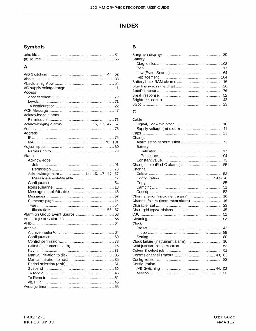
100 MM GRAPHICS RECORDER: USER GUIDE
User GuidePage 117
HA027271Issue 10 Jun 03
Symbols.uhq file ........................................................................ 84n source ..................................................................... 66
AA/B Switching ........................................................ 44, 52About ............................................................................ 83Absolute high/low ........................................................ 54AC supply voltage range ............................................. 11Access
Access when: ........................................................... 72Levels ....................................................................... 71To configuration ....................................................... 22
ACK Message .............................................................. 47Acknowledge alarms
Permission ............................................................... 73Acknowledging alarms............................ 15, 17, 47, 57Add user ...................................................................... 75Address
IP .............................................................................. 76MAC ................................................................ 76, 101
Adjust inputs ................................................................ 80Permission to ........................................................... 73
AlarmAcknowledge
Job ....................................................................... 91Permission ........................................................... 73
Acknowledgement ....................... 14, 15, 17, 47, 57Message enable/disable ...................................... 47
Configuration ........................................................... 54Icons (Channel) ....................................................... 13Message enable/disable .......................................... 46Messages................................................................. 57Summary page ........................................................ 14Type ......................................................................... 54
Illustrations .................................................... 56, 57Alarm on Group Event Source .................................... 63Amount (R of C alarms) ............................................... 55AND ............................................................................. 64Archive
Archive media % full ................................................ 64Configuration ........................................................... 60Control permission ................................................... 73Failed (instrument alarm) ........................................ 16Key ........................................................................... 35Manual initiation to disk ........................................... 35Manual initiation to host ........................................... 36Period selection (disk) ............................................. 61Suspend ................................................................... 35To Media .................................................................. 46To Remote ............................................................... 62via FTP..................................................................... 46
Average time ................................................................ 55
BBargraph displays ........................................................ 30Battery
Diagnostics ............................................................ 102Icon .......................................................................... 17Low (Event Source) ................................................. 64Replacement .......................................................... 104
Battery back RAM cleared ........................................... 16Blue line across the chart ............................................ 26BootP timeout .............................................................. 76Break response............................................................ 52Brightness control ........................................................ 43BSpc ............................................................................ 23
CCable
Signal, Max/min sizes ............................................. 10Supply voltage (min. size) ....................................... 11
Caps ............................................................................. 23Change
Alarm setpoint permission ....................................... 73Battery
Indicator ............................................................... 17Procedure .......................................................... 104
Constant value ......................................................... 73Change time (R of C alarms) ....................................... 55Channel
Colour ...................................................................... 53Configuration .................................................. 48 to 70Copy ......................................................................... 85Damping ................................................................... 51Descriptor ................................................................ 52
Channel error (instrument alarm) ................................ 16Channel failure (instrument alarm) .............................. 16Character set ............................................................... 23Chart grid type/divisions .............................................. 45CJC .............................................................................. 52Cleaning ..................................................................... 103Clock
Preset ....................................................................... 43Job ....................................................................... 89
Setting ...................................................................... 80Clock failure (instrument alarm) .................................. 16Cold junction compensation ........................................ 52Colour B select job ...................................................... 91Comms channel timeout ....................................... 43, 63Config version .............................................................. 83Configuration
A/B Switching .................................................... 44, 52Access ..................................................................... 22
INDEX
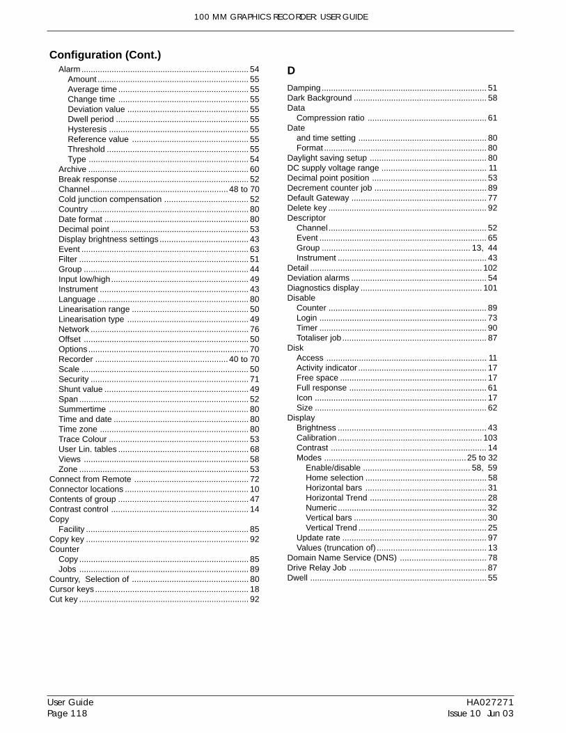
100 MM GRAPHICS RECORDER: USER GUIDE
HA027271Issue 10 Jun 03
User GuidePage 118
Alarm........................................................................ 54Amount ................................................................. 55Average time ........................................................ 55Change time ........................................................ 55Deviation value .................................................... 55Dwell period ......................................................... 55Hysteresis ............................................................ 55Reference value .................................................. 55Threshold ............................................................. 55Type ..................................................................... 54
Archive ..................................................................... 60Break response........................................................ 52Channel ...........................................................48 to 70Cold junction compensation .................................... 52Country .................................................................... 80Date format .............................................................. 80Decimal point ........................................................... 53Display brightness settings ...................................... 43Event ........................................................................ 63Filter ......................................................................... 51Group ....................................................................... 44Input low/high........................................................... 49Instrument ................................................................ 43Language ................................................................. 80Linearisation range .................................................. 50Linearisation type .................................................... 49Network .................................................................... 76Offset ....................................................................... 50Options ..................................................................... 70Recorder ......................................................... 40 to 70Scale ........................................................................ 50Security .................................................................... 71Shunt value .............................................................. 49Span ......................................................................... 52Summertime ............................................................ 80Time and date .......................................................... 80Time zone ................................................................ 80Trace Colour ............................................................ 53User Lin. tables ........................................................ 68Views ....................................................................... 58Zone ......................................................................... 53
Connect from Remote ................................................. 72Connector locations ..................................................... 10Contents of group ........................................................ 47Contrast control ........................................................... 14Copy
Facility ...................................................................... 85Copy key ...................................................................... 92Counter
Copy ......................................................................... 85Jobs ......................................................................... 89
Country, Selection of .................................................. 80Cursor keys .................................................................. 18Cut key ......................................................................... 92
DDamping ....................................................................... 51Dark Background ......................................................... 58Data
Compression ratio ................................................... 61Date
and time setting ....................................................... 80Format ...................................................................... 80
Daylight saving setup .................................................. 80DC supply voltage range ............................................. 11Decimal point position ................................................. 53Decrement counter job ................................................ 89Default Gateway .......................................................... 77Delete key .................................................................... 92Descriptor
Channel .................................................................... 52Event ........................................................................ 65Group ................................................................ 13, 44Instrument ................................................................ 43
Detail .......................................................................... 102Deviation alarms .......................................................... 54Diagnostics display .................................................... 101Disable
Counter .................................................................... 89Login ........................................................................ 73Timer ........................................................................ 90Totaliser job .............................................................. 87
DiskAccess ..................................................................... 11Activity indicator ....................................................... 17Free space ............................................................... 17Full response ........................................................... 61Icon .......................................................................... 17Size .......................................................................... 62
DisplayBrightness ................................................................ 43Calibration .............................................................. 103Contrast ................................................................... 14Modes .............................................................25 to 32
Enable/disable .............................................. 58, 59Home selection .................................................... 58Horizontal bars .................................................... 31Horizontal Trend .................................................. 28Numeric ................................................................ 32Vertical bars ......................................................... 30Vertical Trend ....................................................... 25
Update rate .............................................................. 97Values (truncation of) ............................................... 13
Domain Name Service (DNS) ..................................... 78Drive Relay Job ........................................................... 87Dwell ............................................................................ 55
Configuration (Cont.)
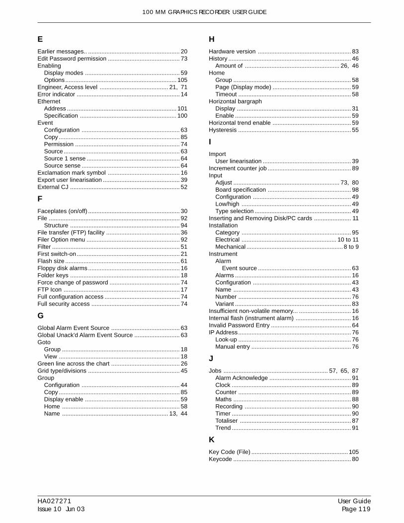
100 MM GRAPHICS RECORDER: USER GUIDE
User GuidePage 119
HA027271Issue 10 Jun 03
EEarlier messages.. ....................................................... 20Edit Password permission ........................................... 73Enabling
Display modes ......................................................... 59Options ................................................................... 105
Engineer, Access level ......................................... 21, 71Error indicator .............................................................. 14Ethernet
Address .................................................................. 101Specification .......................................................... 100
EventConfiguration ........................................................... 63Copy ......................................................................... 85Permission ............................................................... 74Source ...................................................................... 63Source 1 sense ........................................................ 64Source sense ........................................................... 64
Exclamation mark symbol ........................................... 16Export user linearisation .............................................. 39External CJ .................................................................. 52
FFaceplates (on/off) ....................................................... 30File ............................................................................... 92
Structure .................................................................. 94File transfer (FTP) facility ............................................ 36Filer Option menu ........................................................ 92Filter ............................................................................. 51First switch-on.............................................................. 21Flash size ..................................................................... 61Floppy disk alarms ....................................................... 16Folder keys .................................................................. 18Force change of password .......................................... 74FTP Icon ...................................................................... 17Full configuration access ............................................. 74Full security access ..................................................... 74
GGlobal Alarm Event Source ......................................... 63Global Unack'd Alarm Event Source ........................... 63Goto
Group ....................................................................... 18View ......................................................................... 18
Green line across the chart ......................................... 26Grid type/divisions ....................................................... 45Group
Configuration ........................................................... 44Copy ......................................................................... 85Display enable ......................................................... 59Home ....................................................................... 58Name ................................................................ 13, 44
HHardware version ........................................................ 83History .......................................................................... 46
Amount of ......................................................... 26, 46Home
Group ....................................................................... 58Page (Display mode) ............................................... 59Timeout .................................................................... 58
Horizontal bargraphDisplay ..................................................................... 31Enable ...................................................................... 59
Horizontal trend enable ............................................... 59Hysteresis .................................................................... 55
IImport
User linearisation ..................................................... 39Increment counter job .................................................. 89Input
Adjust ................................................................ 73, 80Board specification .................................................. 98Configuration ........................................................... 49Low/high .................................................................. 49Type selection .......................................................... 49
Inserting and Removing Disk/PC cards ...................... 11Installation
Category .................................................................. 95Electrical ......................................................... 10 to 11Mechanical .......................................................... 8 to 9
InstrumentAlarm
Event source ........................................................ 63Alarms ...................................................................... 16Configuration ........................................................... 43Name ....................................................................... 43Number .................................................................... 76Variant ...................................................................... 83
Insufficient non-volatile memory... ............................... 16Internal flash (instrument alarm) ................................. 16Invalid Password Entry ................................................ 64IP Address.................................................................... 76
Look-up .................................................................... 76Manual entry ............................................................ 76
JJobs ............................................................... 57, 65, 87
Alarm Acknowledge ................................................. 91Clock ........................................................................ 89Counter .................................................................... 89Maths ....................................................................... 88Recording ................................................................ 90Timer ........................................................................ 90Totaliser ................................................................... 87Trend ........................................................................ 91
KKey Code (File) .......................................................... 105Keycode ....................................................................... 80

100 MM GRAPHICS RECORDER: USER GUIDE
HA027271Issue 10 Jun 03
User GuidePage 120
LLabelling symbols .......................................................... 7Language selection ..................................................... 80Latched ........................................................................ 54Later messages.. ......................................................... 20Left cursor key ............................................................. 18Line across the chart ................................................... 26Linear chart grid ........................................................... 45Linear scales ................................................................ 50Linearisation function .................................................. 49
User entered ............................................................ 68Local Host .................................................................... 78Log
Chart grid ................................................................. 45Scale ........................................................................ 50
Logged out ................................................................... 21Login ............................................................................ 22
Disable ..................................................................... 73Key ........................................................................... 18
Logout key ................................................................... 71
MMAC Address ...................................................... 76, 101MAIN (Diagnostics) .................................................... 101Maintenance .............................................................. 103Manual archive
To disk ...................................................................... 35To host computer ..................................................... 36
MathsReset Job ................................................................. 88
Maths Channel Partial Failure ..................................... 64Maths Copy .................................................................. 85Maximum number of history files ................................ 61MEDIA (Diagnostics) ................................................. 102Media full event limit .................................................... 62Media size .................................................................... 62Memory size ......................................................... 61, 83Menu structure
Archive Key ............................................................ 112Config Key
Basic recorder .................................................... 113Options ............................................................... 116
Network Key .......................................................... 114Root menu ............................................................. 111Save/R(estore) Key ............................................... 112Security Key ........................................................... 114System Key ............................................................ 115
MessageCopy ......................................................................... 85
Messages..................................................................... 66Alarm ........................................................................ 57Enable/disable ......................................................... 46Entry ......................................................................... 66
Example ............................................................... 67Job ........................................................................... 88Log ........................................................................... 19Operator entered ..................................................... 33
ModbusAddress .................................................................... 43Security disabled ..................................................... 43
NNAND ........................................................................... 64Navigation keys ........................................................... 18Network
Configuration ........................................................... 76Name ....................................................................... 78Specification .......................................................... 100
Network alarms ............................................................ 16New
Configuration ........................................................... 38Key ........................................................................... 92Password ................................................................. 72
No action ...................................................................... 87No chart grid ................................................................ 45NONE ........................................................................... 64NOR ............................................................................. 64Not recommended to archive... ................................... 46Notes, Operator ........................................................... 33Numeric
Display ..................................................................... 53Enable .................................................................. 59
OOffset ........................................................................... 50Offset correction (touch screen) ................................ 103Ok ................................................................................ 23On becoming active/inactive/acknowledged ............... 87Open/Close folder keys ............................................... 18Operator
Access level ...................................................... 21, 71Event logic ............................................................... 64Notes (Messages) ................................................... 33
Option configuration .................................................... 70Options Key ................................................................. 18OR ................................................................................ 64Ovr ............................................................................... 23
PPassword
Force change of ....................................................... 74Passwords ................................................................... 71
Edit permission ........................................................ 73Editing ...................................................................... 71
Paste key ..................................................................... 92Paste/delete file permission ........................................ 74PC Card access ........................................................... 11Point Alarm .................................................................. 63Pollution degree ........................................................... 95Port Usage (TCP) ...................................................... 108Power-up event source................................................ 64Preset
Clock ........................................................................ 43Job ....................................................................... 89
Counter .................................................................... 89Hour/Minute ............................................................. 43Totaliser ................................................................... 73
Job ....................................................................... 87Preventive maintenance ............................................ 103
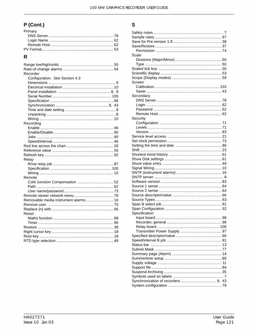
100 MM GRAPHICS RECORDER: USER GUIDE
User GuidePage 121
HA027271Issue 10 Jun 03
PrimaryDNS Server .............................................................. 78Login Name ............................................................. 62Remote Host ............................................................ 62
PV Format .................................................................... 53
RRange low/high/units ................................................... 50Rate-of-change alarms ................................................ 54Recorder
Configuration. See Section 4.3Dimensions ................................................................ 9Electrical installation ................................................ 10Panel installation .................................................. 8, 9Serial Number ........................................................ 105Specification ............................................................ 96Synchronization .................................................. 8, 43Time and date setting ................................................ 8Unpacking .................................................................. 8Wiring ....................................................................... 10
RecordingEnable ...................................................................... 46Enable/Disable ......................................................... 90Jobs ......................................................................... 90Speed/interval .......................................................... 46
Red line across the chart ............................................. 26Reference value .......................................................... 55Refresh key .................................................................. 92Relay
Rrive relay job .......................................................... 87Specification .......................................................... 100Wiring ....................................................................... 10
RemoteCold Junction Compensation .................................. 52Path .......................................................................... 62User name/password ............................................... 73
Remote viewer network menu ..................................... 76Removable media instrument alarms .......................... 16Remove user ............................................................... 75Replace n with ........................................................... 66Reset
Maths function ......................................................... 88Timer ........................................................................ 90
Restore ........................................................................ 38Right cursor key ........................................................... 18Root key ....................................................................... 18RTD type selection ...................................................... 49
SSafety notes ................................................................... 7Sample rates ................................................................ 97Save for Pre version 1.8 .............................................. 38Save/Restore ............................................................... 37
Permission ............................................................... 74Scale
Divisions (Major/Minor) ............................................ 50Type ......................................................................... 50
Scaled tick box ............................................................ 50Scientific display .......................................................... 53Scope (Display modes) ............................................... 59Screen
Calibration .............................................................. 103Saver ........................................................................ 43
SecondaryDNS Server .............................................................. 78Login ........................................................................ 62Password ................................................................. 62Remote Host ............................................................ 62
SecurityConfiguration ........................................................... 71Levels ....................................................................... 71Version ..................................................................... 83
Service level access .................................................... 21Set clock permission .................................................... 73Setting the time and date ............................................ 80Shift .............................................................................. 23Shortest trend history .................................................. 61Show Disk settings ...................................................... 61Shunt value entry ......................................................... 49Signal Wiring ................................................................ 10SNTP (instrument alarms) ........................................... 16SNTP server .................................................................. 8Software version .......................................................... 83Source 1 sense ............................................................ 64Source 2 sense ............................................................ 64Source descriptor/value ............................................... 66Source Types ............................................................... 63Span B select job ......................................................... 91Span Configuration ...................................................... 52Specification
Input board ............................................................... 98Recorder, general .................................................... 96Relay board ........................................................... 100Transmitter Power Supply ....................................... 97
Specified descriptor/value ........................................... 66Speed/interval B job .................................................... 91Status bar .................................................................... 13Subnet Mask ................................................................ 77Summary page (Alarm) ............................................... 14Summertime setup ...................................................... 80Supply voltage ............................................................. 11Support file ................................................................... 84Suspend Archiving ....................................................... 35Symbols used on labels ................................................ 7Synchronization of recorders.................................. 8, 43System configuration ................................................... 79
P (Cont.)

100 MM GRAPHICS RECORDER: USER GUIDE
HA027271Issue 10 Jun 03
User GuidePage 122
TTag, Channel ................................................................ 52TCP port usage .......................................................... 108Text
Save and Restore .................................................... 38String entry .............................................................. 23
Thermocouple type selection ...................................... 49Threshold ..................................................................... 55Time
Change annotation .................................................. 26Format ...................................................................... 80Permission to set ..................................................... 73Setting ...................................................................... 80To fill disk/memory ................................................... 62Zone selection ......................................................... 80
Time synch. instrument alarm .................................... 16Timeout ........................................................................ 58
Comms chammel ..................................................... 43Timer
Copy ......................................................................... 85Jobs ......................................................................... 90Timer Active Event Source ...................................... 63
TotaliserCopy ......................................................................... 85Jobs ......................................................................... 87
Touch Cal ................................................................... 102Touch screen
Calibration .............................................................. 103Precautions ............................................................ 103
TraceColour ...................................................................... 53History, maximum ................................................... 46History display ......................................................... 46
Transmitter Power Supply specification ...................... 97Trend
HistoryDuration ............................................................... 46Shortest ................................................................ 61
History display ......................................................... 26Interval/Speed/Units ................................................ 44Jobs ......................................................................... 91Speed/interval .......................................................... 45Trend speed/interval B job ...................................... 91
Trigger .......................................................................... 54Truncation of display values ........................................ 13
UUn'ackd Alarm on group .............................................. 63Unack'd point alarm ..................................................... 63Unlatched ..................................................................... 54Unsupported File message ......................................... 38User
Adding and removing ............................................... 75Password ................................................................. 75
User linearisation tableConfiguration ........................................................... 68Importing/Exporting ................................................. 39
User logged in Event Source ....................................... 64
VValue entry ................................................................... 23Version numbers .......................................................... 83Vertical bargraph
Display ..................................................................... 30Enable ...................................................................... 59
Vertical trend enable .................................................... 59Views configuration ..................................................... 58
WWhilst active/inactive/unacknowledged ....................... 87Wiring
Relay ........................................................................ 10Signal ....................................................................... 10
Max/min wire sizes .............................................. 10Maximum torque .................................................. 10
Supply voltage ......................................................... 11
XX points ........................................................................ 68XOR ............................................................................. 64
YY points ........................................................................ 68
ZZone B select job ......................................................... 91Zone configuration ....................................................... 53

Great BritainEurotherm Limited,Faraday Close,Worthing,West Sussex BN13 3PL
Telephone: +44 (0)1903 695888Fax: +44 (0)1903 695666
e-mail:[email protected]: [email protected]
http://www.eurotherm.co.ukHong KongEurotherm Limited,Unit D, 18/F Gee Chang Hong Centre,65, Wong Chuk Hang Road,Aberdeen.
Telephone: 852 2873 3826Fax: 852 2870 0148
e-mail:[email protected]
IndiaEurotherm DEL India Limited,152, Developed Plots Estate,Perungudi,Chennai 600 096,
Telephone: 91 44 4961129Fax: 91 44 4961831
e-mail: [email protected]://www.eurothermdel.com
ItalyEurotherm SpA,Via XXIV Maggio,I-22070 Guanzate,Como.
Telephone: 39 031 975111Fax: 39 031 977512
e-mail:[email protected]://www.eurotherm.it
JapanDensei Lambda K.K.,Strategic Products Dept.5F Nissay Aroma Square,37-1, Kamata, 5-Chome,Ohta-ku,Tokyo 144-8721
Telephone: 81 3 5714 0620Fax: 81 3 5714 0621
e-mail (Sales): [email protected] (Technical): [email protected]
http://www.densei-lambda.comKoreaEurotherm Korea Limited,J- Building402-3Poongnab-Dong,Songpa-KuSeoul, 138-040
Telephone: 82 2 478 8507Fax: 82 2 488 8508
Inter-Company sales and service locationsNetherlandsEurotherm BV,Genielaan 4,2404CH Alphen aan den Rijn,The Netherlands
Telephone: 31 172 411 752Fax: 31 172 417 260
e-mail: [email protected]://www.eurotherm.nl
NorwayEurotherm A/S,Vollsveien 13D1366 Lysaker,Postboks 227NO-1326 LysakerNorway,
Telephone: 47 67 592170Fax: 47 67 118301
http://www.eurotherm.noSpainEurotherm España SA,Pol. Ind. De Alcobendas,Calle de la Granja 74,28108 Alcobendas,Madrid.
Telephone: 34 91 661 60 01Fax: 34 91 661 90 93
http://www.eurotherm.es
SwedenEurotherm AB,Lundavägen 143,S-21224 Malmö.
Telephone: 46 40 38 45 00Fax: 46 40 38 45 45
e-mail:[email protected]://www.eurotherm.se
SwitzerlandEurotherm Produkte (Schweiz) AG,Schwerzistraße, 20,CH-8807 Freienbach.
Telephone: 41 55 415 44 00Fax: 41 55 415 44 15
e-mail:[email protected]://www.eurotherm.ch
United States of AmericaEurotherm Recorders Inc.741-F Miller DriveLeesburgVA 20175-8993
Telephone: 1 703 669 1342Fax: 1 703 669 1307
e-mail (Sales): [email protected] (Technical): [email protected]
http://www.chessell.com
Specification subject to change without notice. ©Eurotherm Limited.
AustraliaEurotherm Pty. Limited.Unit 10.40 Brookhollow Avenue,Baulkham Hills,NSW 2153
Telephone: 61 2 9634 8444Fax: 61 2 9634 8555
e-mail: [email protected]://www.eurotherm.com.au
AustriaEurotherm GmbHGeiereckstraße 18/1,A1110 Wien,
Telephone: 43 1 798 76 01Fax: 43 1 798 76 05
e-mail:[email protected]://www.eurotherm.at
Belgium and LuxemburgEurotherm S.A./N.V.Rue du Val-Notre-Dame 384,4520 Moha (Huy)Belgium
Telephone: 32 (0) 85 274080Fax: 32 (0) 85 274081
e-mail: [email protected]:/www.eurotherm.nl
DenmarkEurotherm Danmark A/SFinsensvej 86,DK 2000 Fredriksberg,
Telephone: +45 (38) 871622Fax: +45 (38) 872124
e-mail: [email protected]
FinlandEurotherm Finland,Aurakatu 12A,FIN-20100 Turku
Telephone: 358 2 25 06 030Fax: 358 2 25 03 201
FranceEurotherm Automation Division ChessellParc d'Affaires,6, Chemin des Joncs,BP55F - 69574 Dardilly, CEDEX
Telephone: 33 0 4 78 66 55 20Fax: 33 0 4 78 66 55 35
e-mail: [email protected]://www.eurotherm-chessell.fr
GermanyEurotherm Deutschland GmbHOttostraße 1,65549 Limburg
Tel: +49 (0) 64 31/2 98 - 0Fax: +49 (0) 64 31/2 98 - 1 19
e-mail:[email protected]://www.eurotherm-deutschland.de
EUROTHERM LIMITEDFaraday Close, Durrington, Worthing, West Sussex, BN13 3PL
Telephone: 01903 695888 Facsimile: 01903 695666e-mail: [email protected]
Website: http://www.eurotherm.co.uk
HA027271/10 (CN14763)
EUROTHERM


Related Documents