1 User Hand book The Hand book will help to understand the re-designed removing process with the implemented solution. Now all lifting is without any dangerous swing or capsize executed. The workplace is safe and without risk of injury and health of workers. How to understand and execute the task is visualized and explained in the following picture series. It is taking care of safety, ease of mounting and complexity of construction. The moving process is to execute in steps from 1 – 15 The lifting operation require the following to be considered Cultural, communication and language difficulties Environmental conditions (when the hoist is under free sky) Weight size and centre of gravity of load Lighting the pickup and lay down areas Available of approved lifting points on load Method of slinging/attaching/detaching the load Working under suspended loads Access and emergency escape routes Suitability and condition of lifting equipment to be used Experience, competence and training of personal Initial and final load positions and how it will get there Number of personnel required for the task Pre-use inspection of equipment by operator Visibility of load Evaluate step by step before the task

Welcome message from author
This document is posted to help you gain knowledge. Please leave a comment to let me know what you think about it! Share it to your friends and learn new things together.
Transcript

1
User Hand book The Hand book will help to understand the re-designed removing process with the implemented solution.
Now all lifting is without any dangerous swing or capsize executed. The workplace is safe and without risk
of injury and health of workers.
How to understand and execute the task is visualized and explained in the following picture series. It is
taking care of safety, ease of mounting and complexity of construction. The moving process is to execute in
steps from 1 – 15
The lifting operation require the following to be considered
Cultural, communication and language difficulties Environmental conditions (when the hoist is under free sky) Weight size and centre of gravity of load Lighting the pickup and lay down areas Available of approved lifting points on load Method of slinging/attaching/detaching the load Working under suspended loads
Access and emergency escape routes Suitability and condition of lifting equipment to be used Experience, competence and training of personal Initial and final load positions and how it will get there Number of personnel required for the task Pre-use inspection of equipment by operator Visibility of load
Evaluate step by step before the task
2
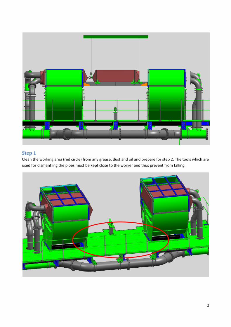
Step 1 Clean the working area (red circle) from any grease, dust and oil and prepare for step 2. The tools which are
used for dismantling the pipes must be kept close to the worker and thus prevent from falling.
3
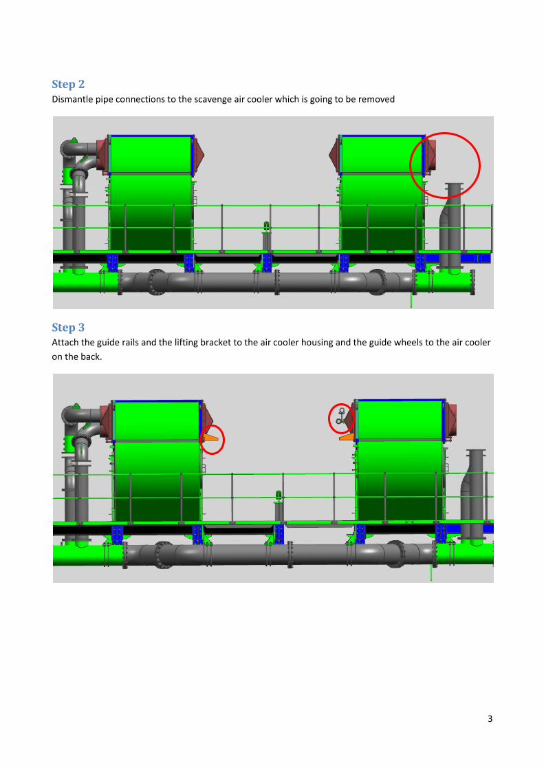
Step 2 Dismantle pipe connections to the scavenge air cooler which is going to be removed
Step 3 Attach the guide rails and the lifting bracket to the air cooler housing and the guide wheels to the air cooler
on the back.

4
Step 4 Open the walking gallery where the air cooler will pass through.
Step 5
Remove the beams where the work frame and air cooler pass through.
5
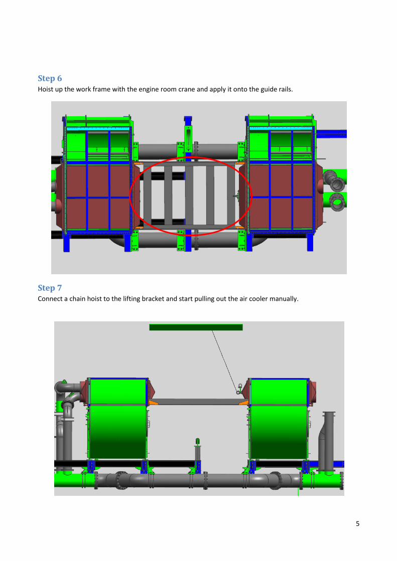
Step 6 Hoist up the work frame with the engine room crane and apply it onto the guide rails.
Step 7 Connect a chain hoist to the lifting bracket and start pulling out the air cooler manually.
6
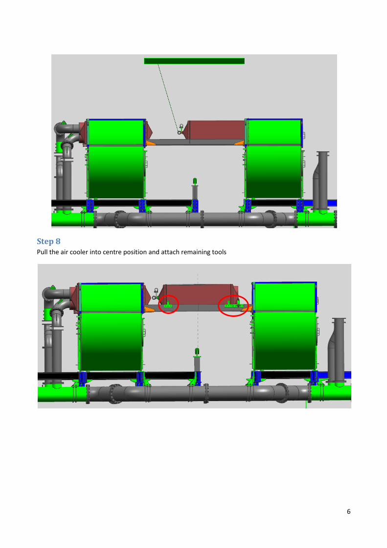
Step 8 Pull the air cooler into centre position and attach remaining tools

7
Step 9 Attach hoist chains at five points 1 – 5 on the work frame and the air cooler. Attachment tools 6 – 9 are
fixed to the air cooler and keep the cooler attach to the frame. Point 1 and 3 also make sure that the air
cooler is in centre position thus the cooler cannot be pushed any further. 1 and 3 are positioned on the
inside of the work frame.
1
2
3
4
5
6 7
6 7
8 9
8
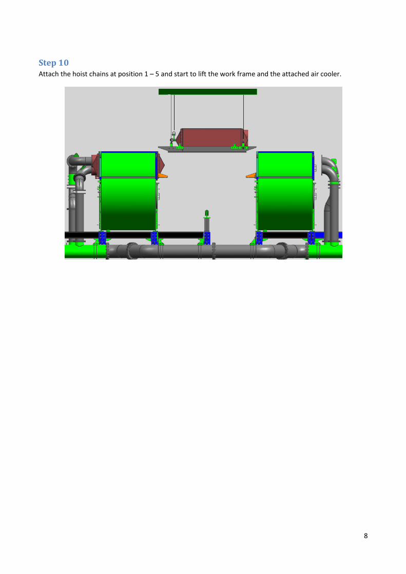
Step 10 Attach the hoist chains at position 1 – 5 and start to lift the work frame and the attached air cooler.

9
Step 11 Start to tilt the air cooler slowly in upward position. The two chains at the back support the tilting process
and help to prevent any dangerous swing.

10
Step 11 The tilting process is seen from the back, where the two chains support the tilting.
11
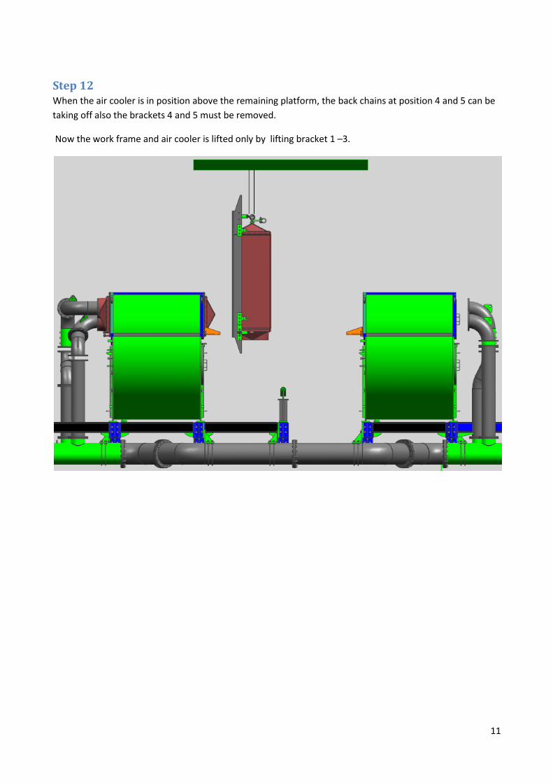
Step 12 When the air cooler is in position above the remaining platform, the back chains at position 4 and 5 can be
taking off also the brackets 4 and 5 must be removed.
Now the work frame and air cooler is lifted only by lifting bracket 1 –3.
12
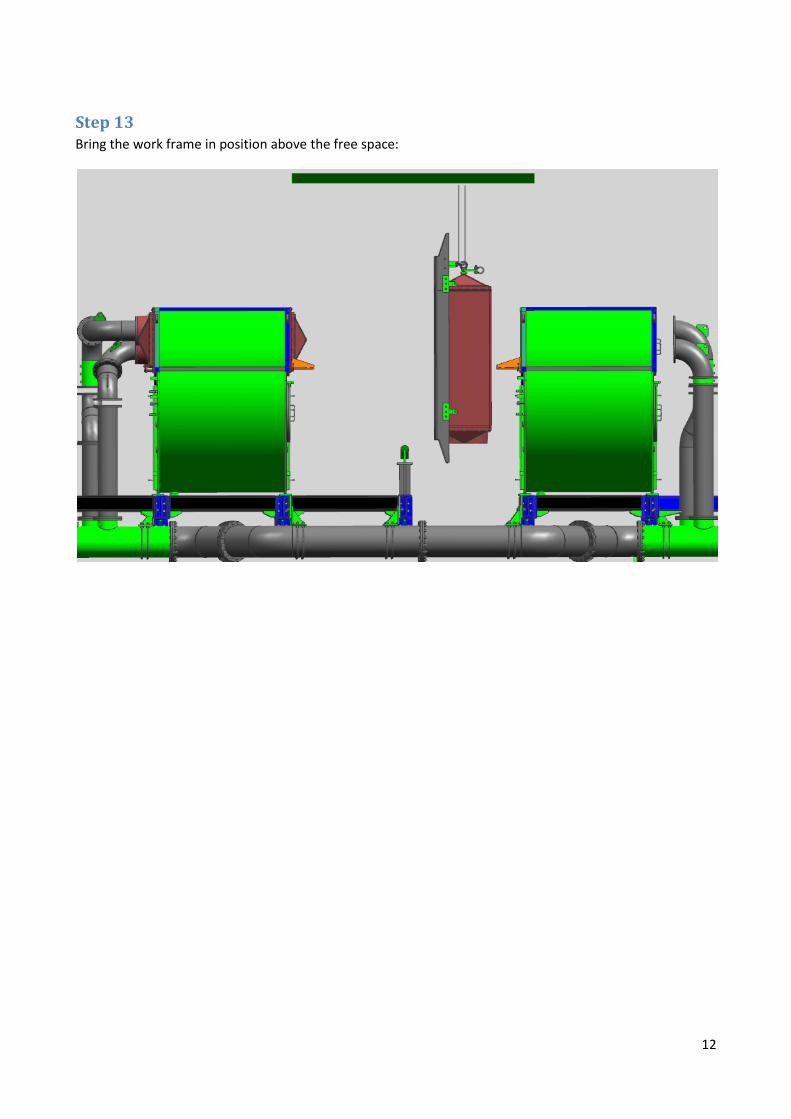
Step 13 Bring the work frame in position above the free space:

13
Step 14 Start the lowering process.

14
Step 15 When the chain hoist exceeds its limit than the engine room crane takes over.
Related Documents