USER AND MAINTENANCE MANUAL TICKNESS AND LIPPING PLANER Art. 0686/200 TRANSLATION OF THE ORIGINAL INSTRUCTIONS

Welcome message from author
This document is posted to help you gain knowledge. Please leave a comment to let me know what you think about it! Share it to your friends and learn new things together.
Transcript

USER AND MAINTENANCEMANUAL
TICKNESS AND LIPPING PLANER
Art. 0686/200
TRANSLATION OF THE ORIGINAL INSTRUCTIONS

MACHINES ANDACCESSORIES
Page 2 of 47
PREFACE
Read this manual before carrying out any operation
ORIGINAL INSTRUCTIONS
Please ensure you have read the owner’s manual before operating the planer. All theinstructions in this manual must be applied rigorously to ensure optimum machineperformance.
Operator Qualifications
Please ensure all machine operators are given all required information and adequatesafety instruction and training in:a) Machine operating conditions;b) Foreseeable abnormal situations;c) pursuant to art. 73 of Legislative Decree 81/08.
We guarantee the Machine's conformity to specifications and technical instructions
described in the Manual on the date of issue, listed on this page; however, the
machine may be subject to potentially major technical changes in future, without the
Manual being updated.
Therefore, contact FERVI for information about modifications that could be
implemented.
REV. 1 April 2013

MACHINES ANDACCESSORIES
Page 3 of 47
TABLE OF CONTENTS
1. INTRODUCTION......................................................................................5
1.1 Preface..........................................................................................................................6
2. SAFETY...................................................................................................7
2.1 General safety rules ......................................................................................................7
2.2 Safety regulations for electric machines .......................................................................9
2.3 Technical assistance ...................................................................................................10
2.4 Other Provisions .........................................................................................................10
3. TECHNICAL SPECIFICATIONS...............................................................11
4. MACHINE DESCRIPTION.......................................................................12
4.1 Suction system............................................................................................................13
4.2 Main parts of the Planer. 0686/200 ............................................................................14
4.3 Identification plates....................................................................................................15
4.4 Pictograms..................................................................................................................15
5. DESCRIPTION OF CONTROLS................................................................17
5.1 On and off switches ....................................................................................................17
5.2 Emergency button.......................................................................................................18
5.3 Reset button ...............................................................................................................19
5.4 Adjustment knobs work tables and shelters ...............................................................20
6. MACHINE SAFETY DEVICES ..................................................................22
6.1 Electric safety devices.................................................................................................22
6.2 Safety devices against "mechanical" risks ..................................................................226.2.1 Protective casing of the transmission of motion ........................................................... 226.2.2 Planer shaft guard (cutting blades) ............................................................................ 236.2.3 Cutterhead and sawdust collection interlocked protective covers.................................... 23
6.3 Use of PPE...................................................................................................................24
7. IMPROPER USE AND CONTRAINDICATIONS .........................................25
8. TRANSPORT AND LIFTING....................................................................25
9. INSTALLATION AND COMMISSIONING.................................................26
9.1 Machine delivery and unpacking .................................................................................26
9.2 Assembly ....................................................................................................................27
9.3 Positioning..................................................................................................................27
9.4 Electrical connection ...................................................................................................28
10. OPERATION..........................................................................................29
10.1 Precautions for use ..................................................................................................29
10.2 Starting/Stopping....................................................................................................29

MACHINES ANDACCESSORIES
Page 4 of 47
10.3 How to configure the lipping planer .........................................................................30
10.4 Configuration for " thickness" planing .....................................................................33
10.5 How to perform safe planing....................................................................................3510.5.1 Surface planing........................................................................................................ 3510.5.2 Lipping planing ........................................................................................................ 3610.5.3 Planing pieces of greater thickness............................................................................. 3610.5.4 Planing short workpieces........................................................................................... 3710.5.5 Planing with 45° inclined guide .................................................................................. 3710.5.6 Strip planing ........................................................................................................... 3710.5.7 Thicknessing ........................................................................................................... 38
11. MAINTENANCE .....................................................................................38
11.1 Ordinary maintenance..............................................................................................3811.1.1 Routine at the end of each processing ........................................................................ 38
11.2 Periodically ..............................................................................................................39
11.3 Lubrification.............................................................................................................39
11.4 Checking/replacing the drive belts ..........................................................................40
11.5 Replacing the cutting blades....................................................................................41
12. DISPOSAL OF COMPONENTS AND MATERIALS......................................41
13. TROUBLESHOOTING .............................................................................42
14. ELECTRIC CIRCUIT ...............................................................................43
15. REPLACEMENT PARTS...........................................................................44

MACHINES ANDACCESSORIES
Page 5 of 47
1.INTRODUCTIONThe purpose of this manual is to provide the knowledge necessary for the use andmaintenance of the Thickness and lipping planer Art. 0686/200, and create a sense ofresponsibility and a knowledge of the possibilities and limitations of the tool entrusted to theoperator.
As the machine is entrusted to experienced and skilled operators, the following machine mustbe perfectly known by the operator if you want it to be used safely and effectively.
The selection of personnel is an important factor for the purposes of efficiency and safety inthe workplace, and the people considered suitable to perform a specific job must have thesufficient physical and mental capacity to allow them to understand the instructions that theyare given.
GRAPHIC REPRESENTATION OF SAFETY, OPERATIONAL AND RISK WARNINGS
The following boxes are designed to attract the attention of the reader / user for the properand safe use of the machine:
Pay Attention
This emphasizes behavioral rules to avoid damaging the machine and/or the occurrence ofhazardous situations.
Residual Risks
This emphasizes the presence of hazards causing residual risks which the operator mustwatch for to avoid personal injury or property damage.

MACHINES ANDACCESSORIES
Page 6 of 47
1.1 PrefaceRead this manual carefully to acquire full knowledge of the machine and general precautionsto be observed during operation. In other words, the life and performance of the Planer aredependent on how it is used.
Follow the instructions contained herein, in addition to the general precautions to be observedwhile working. Even if the operator is already familiar with the planer, it is necessary to:
1. Acquire full knowledge of the machine.
2. Read this manual carefully to understand: operation, safety devices and all necessaryprecautions. All this is to allow safe use of the machine.
3. Wear appropriate clothing for the job.
4. The operator must wear appropriate clothing to prevent the occurrence of unpleasantaccidents.
5. Take proper care of the machine.
Using the Machine
The machine must only be used by qualified personnel trained to use the machine byauthorized personnel.

MACHINES ANDACCESSORIES
Page 7 of 47
2.SAFETY
2.1 General safety rules
Machine risks
DO NOT underestimate the risks associated with using the machine and concentrate on thework in progress.
Machine risks
All accident prevention measures reported in this manual must be observed even when allsafety devices are implemented for safe machine operation.
Machine risks
Every person responsible for machine operation and maintenance is required to have read theinstruction manual first and specifically the chapter on safety instructions.It is recommended that the plant safety manager get written confirmation of theabove.
Operator Protection
Before starting any type of work on the machine, the operator must wear appropriatepersonal protective equipment (PPE) such as goggles and gloves.
1. Read this manual carefully, and then work safely.
2. Always check the efficiency and integrity of the machine.
3. Keep your working area clean to prevent damage.
4. Do not start the machine in an enclosed or poorly ventilated area, or in the presence ofa flammable and/or explosive atmosphere. Do not use the machine in damp and/or wetlocations, or those exposed to rain.
5. Avoid starting accidentally.
6. Make sure that the work environment is forbidden to children, non-employees andanimals.
7. Before starting the machine, get used to ensuring that no remaining maintenance andservice keys are inserted. Keep the work environment tidy.
8. Do not force the machine. Use tools appropriate to the seriousness of the job.
9. Do not perform tasks on the machine other than those for which it was designed. Onlyuse the machine in the manner in which it was intended, as described in this instructionmanual.
10. Always wear eye protection and protective gloves while working. If dust is produced, useappropriate masks.
11. Wear appropriate clothing. Loose and dangling clothing, jewellery, long hair, etc. can getcaught in moving parts or the blade, causing permanent injuries.
12. Keep the workplace tidy and free from obstruction; untidiness causes accidents.
13. Always connect the appliance for vacuuming of the sawdust.
14. Do not pull the cord to unplug. Keep it away from heat, oil or sharp edges.

MACHINES ANDACCESSORIES
Page 8 of 47
15. Always work in safety. Take all precautions to avoid accidental contact with the movingparts.
16. Periodically check the stability of the machine.
17. Maintain the machine with care and clean in its entirety. Keep cutting tools clean andsharp. Follow instructions for lubricating and changing accessories. Periodically check thecondition of the power cables.
18. Replace worn and/or damaged parts, check that the repairs and protection workcorrectly before operating. If necessary, have it checked by Technical Support staff. Useonly original spare parts.
19. Check the machine for damaged parts. Before you use the machine after thereplacement/repair of the parts you need to check that it is working properly. Check foralignment and connection of moving parts, failures, the correct mounting.
20. Pay maximum attention to what you are doing and use common sense when you use themachine. Use the machine only when in good physical condition (never when you aretired).
21. The use of accessories or devices other than those recommended in this instructionmanual and may pose a risk to the safety of the operator.
22. Repairs may only be carried out by qualified and authorised personnel.
23. Do not use the machine if the caps are not in their designated position and correctlyadjusted. Each part of the blade not used for planing should be protected.
24. Do not use blades which are not sharpened because this increases the risk of rejection(return back) of the workpiece.
25. When planing short and/or tight workpieces, use the push-piece tool to push themtowards the blade.
26. Do not use the machine to make grooves.
27. The effectiveness of the workpiece anti-rejection device and the feed roller should bechecked periodically.
28. Work without disturbances.
29. Work only with good lighting.
30. Do not leave the tool unattended until the blade and other moving parts, are completelyshut down. To do this, use the shutdown command to stop the machine.
31. Unplug the power cord of the machine from the power socket when:
the machine is not in use;
the machine is left unattended;
after maintenance or registration, the machine does not work properly;
the power supply cable is damaged;
replacing the cutting tool;
moving or transporting the machine;
cleaning.
32. Users of this manual for maintenance and repair are required to have basic knowledge ofmechanical principles and procedures inherent in technical repair.
33. The company safety officer is required to make sure that machine operatorshave read and understood this manual in its entirety.
34. Management is responsible for safety and verification of the company's riskstatus according to Legislative Decree 81/08.

MACHINES ANDACCESSORIES
Page 9 of 47
2.2 Safety regulations for electric machines
Changes in the Electrical System
1. Do not modify the electrical system in any way. Any attempt in this regard mayjeopardize the operation of electrical devices, thus causing malfunction or accident.
2. Work carried out in the electrical system of the machine must, therefore, be carried outonly by qualified and authorized personnel.
3. If you hear unusual noises, or feel something strange, immediately stop the machine.Then carry out an inspection and, if necessary, perform any repairs as required.
4. The supply voltage must correspond to that stated on the label and in the technicalspecifications (230 V / 50 Hz). Never use any other type of power supply!
5. It is recommended the use of a life saving device on the power supply line for a trip rangefrom 10 to 30 mA nominal. For more detailed information, contact a trusted electrician.
6. The socket must be earthed. Extension cables must have sections that are the same orgreater than the sections of the power cable of the machine.
7. Make sure that the power cord does not come into contact with hot objects, wet surfaces,oil or sharp edges.
8. The power cord should be checked regularly and before each use to check for signs ofdamage or wear. If these are not in good condition, do not use the machine and replacethe cable.

MACHINES ANDACCESSORIES
Page 10 of 47
2.3 Technical assistanceFor any problems or concerns, please contact, without hesitation, the Customer ServiceDepartment of the dealer from whom you purchased the product, who has competent andspecialised staff, specific equipment and spare parts.
2.4 Other ProvisionsIt is forbidden to tamper with safety devices
Check the presence and integrity of protections and the proper functioning of safety devicesbefore starting operation.
Do not use the Planer in case of defects!
It is strictly forbidden to modify or remove guards, safety devices, labels andcaution signs.

MACHINES ANDACCESSORIES
Page 11 of 47
3.TECHNICAL SPECIFICATIONS
Description (measurement unit) Art. 0686/200
Overall size (mm) 770 x 430 x 450 (h)
Rated voltage (V) 230
Power (W) 1,250
Frequency (Hz) 50
Blade shaft rotations (RPM) 8,000
Blade shaft diameter (mm) 50
Number of blades 2
Net weight (kg) 25
Loadless acoustic pressure level (dB (A)) 83
Loaded acoustic pressure level (dB (A)) 83
Loadless acoustic pressure level at operator's workstation (dB(A))
101.2
Acoustic pressure level under load at operator workstation dB(A))
102.1
Vibration measured by the hand-arm system (m/s2) 2.31
Planer configuration Art. 0686/200
Cutting capacity (mm) 204 x 2
Bracket size (mm) 500 x 90
Bracket angle (°) 90° - 135°
Table size (mm) 737 x 210
Thickness Planer configuration Art. 0686/200
Cutting capacity (mm) 204 x 2 x 120
Table size (mm) 250 x 204

MACHINES ANDACCESSORIES
Page 12 of 47
4.MACHINE DESCRIPTIONThe THICKNESS PLANER (ART. 0686/200) is a machine designed to plane a surface andgive a piece of wood one predetermined thickness.
When planing, the piece of wood is pushed forward over the cutterhead and scraped thebottom surface. Excised thickness is adjustable by turning the feed table height.
When thicknessing, the wooden piece rests on adjustable floor height of planer and advancingunder the cutterhead, the top surface is scraped.
The machine is designed for processing wooden planks.
Other types of use, or the extension of use beyond that envisaged, does notcorrespond to the designation attributed by the manufacturer, and therefore thelatter cannot accept any responsibility for any damages resulting therefrom.
Intended use and materials
The Planer has been designed and manufactured for the use specified; a different use andnon-observance of the technical parameters laid down by the manufacturer may bedangerous to operators.In particular, with regard to the type of material, DO NOT use the machine for non-woodmaterials.
The planer consists of:
The main frame, entrance and exit tables of the lipping planer and the work platform ofthe thickness Planer;
electric motor and its pull rollers;
two cutterhead blades (cutting tools);
on and off buttons and thickness adjustment devices.
Conversely, the Planer differs primarily for means of protection (crankcase, micro-switches,etc.) used to set the machine in safety in the transition from one job to another configuration.
For a detailed view of the various parts of the machine, refer to paragraph 4.1 of this manual.
The motor works at constant speed: there is no rotation speed adjuster.
The Planer must be installed and used on a flat, stable surface and adequate resistance.
The Planer is designed and intended for use in enclosed workplaces (production departments,warehouses, etc.).
The best performance can be obtained only if certain conditions are met:
use within the temperature range from -5 to +40° C;
relative humidity from 30% to 95%, non-condensing;
height above sea level max. 1000 m.
The environment must also be sufficiently well lit to ensure maximum operational safety (atleast 50 lux is recommended).

MACHINES ANDACCESSORIES
Page 13 of 47
4.1 Suction systemThe Planer must peremptorily be connected to a dust suction device before each use. Thesuction device must have an air flow with a minimum speed of 20 m/s.
The appliance's suction tube for sawdust and dust, must be connected to the suction nozzleas follows:
Art. 0686/200: Lipping planer configured for planing: the suction nozzle is placed underthe work table;
Planer for planing configured "thicknessing": the suction nozzle ispositioned above the work table.
It is important to respect the environment: to dispose of the shavings in compliance withcurrent legislation.

MACHINES ANDACCESSORIES
Page 14 of 47
4.2 Main parts of the Planer. 0686/200
Figure 1 – main parts of “lipping” Planer – Art. 0686/200.
6 Work tables (lipping planer) 9 Lateral guide
7 Fixed front cover 10 Moveable guard cutterhead guard
8 On / off buttons
Figure 2 – main parts Planer "thickness" – Art. 0686/200.
11 Interlocked blade protectioncrankcase
13 Suction nozzle
12 Power cable 14 Work platform ("thickness" Planer)
69
6
8
107
13
14
11
12
MACHINES ANDACCESSORIES
Page 15 of 47
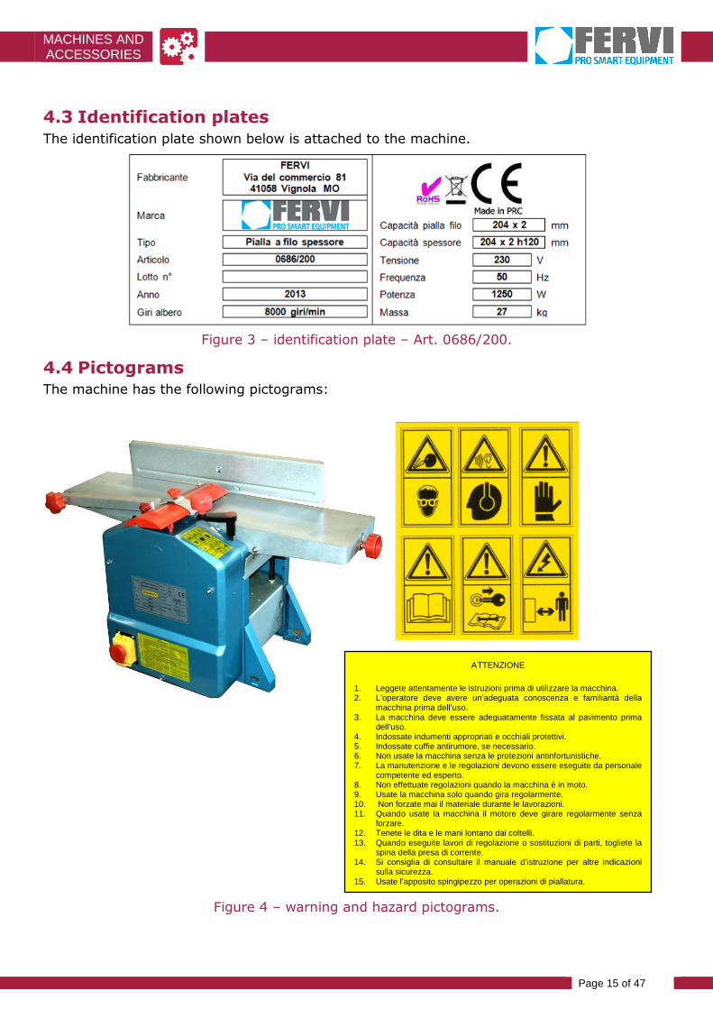
4.3 Identification platesThe identification plate shown below is attached to the machine.
Figure 3 – identification plate – Art. 0686/200.
4.4 PictogramsThe machine has the following pictograms:
Figure 4 – warning and hazard pictograms.
ATTENZIONE
1. Leggete attentamente le istruzioni prima di utilizzare la macchina.2. L’operatore deve avere un’adeguata conoscenza e familiarità della
macchina prima dell’uso.3. La macchina deve essere adeguatamente fissata al pavimento prima
dell’uso.4. Indossate indumenti appropriati e occhiali protettivi.5. Indossate cuffie antirumore, se necessario.6. Non usate la macchina senza le protezioni antinfortunistiche.7. La manutenzione e le regolazioni devono essere eseguite da personale
competente ed esperto.8. Non effettuate regolazioni quando la macchina è in moto.9. Usate la macchina solo quando gira regolarmente.10. Non forzate mai il materiale durante le lavorazioni.11. Quando usate la macchina il motore deve girare regolarmente senza
forzare.12. Tenete le dita e le mani lontano dai coltelli.13. Quando eseguite lavori di regolazione o sostituzioni di parti, togliete la
spina della presa di corrente.14. Si consiglia di consultare il manuale d’istruzione per altre indicazioni
sulla sicurezza.15. Usate l’apposito spingipezzo per operazioni di piallatura.

MACHINES ANDACCESSORIES
Page 16 of 47
Description
PLATE IN ITALIAN PLATE IN ENGLISH
ATTENZIONE
1. Leggete attentamente le istruzioni prima di utilizzare lamacchina.
2. L’operatore deve avere un’adeguata conoscenza efamiliarità della macchina prima dell’uso.
3. La macchina deve essere adeguatamente fissata alpavimento prima dell’uso.
4. Indossate indumenti appropriati e occhiali protettivi.
5. Indossate cuffie antirumore, se necessario.
6. Non usate la macchina senza le protezioniantinfortunistiche.
7. La manutenzione e le regolazioni devono essere eseguiteda personale competente ed esperto.
8. Non effettuate regolazioni quando la macchina è in moto.
9. Usate la macchina solo quando gira regolarmente.
10. Non forzate mai il materiale durante le lavorazioni.
11. Quando usate la macchina il motore deve girareregolarmente senza forzare.
12. Tenete le dita e le mani lontano dai coltelli.
13. Quando eseguite lavori di regolazione o sostituzioni di parti,togliete la spina della presa di corrente.
14. Si consiglia di consultare il manuale d’istruzione per altreindicazioni sulla sicurezza.
15. Usate l’apposito spingipezzo per operazioni di piallatura.
ATTENTION!!
1. Read the instructions carefully before using the machine.
2. The operator must have adequate knowledge and familiarity ofthe machine before use.
3. The machine must be securely fastened to the floor before use.
4. Wear appropriate clothing and protective goggles.
5. Wear ear protection if necessary.
6. Do not use the machine without the safety guards.
7. Maintenance and adjustments must be performed by skilledand experienced staff.
8. Do not make adjustments while the machine is running.
9. Use the machine only when it is running smoothly.
10. Never force the material during processing.
11. When using the machine, the motor should run smoothlywithout forcing.
12. Keep your fingers and hands away from the knives.
13. When performing any adjustment or replacement of parts,remove the plug from the socket.
14. Please consult the instruction manual for other safetyguidelines.
15. Use the appropriate pusher for planing operations.

MACHINES ANDACCESSORIES
Page 17 of 47
5.DESCRIPTION OF CONTROLS
5.1 On and off switchesThe Planer command buttons of the are at the bottom of the front guard, as shown by the redline in Figure 5.
The green button (I) starts the Planer. By pressing this button, the electric motor is poweredand the cutterhead and grooved pull rollers are put into rotation.
When the machine starts, push the yellow cap towards the clamp, without clamping it.
Machine start-up
When you press the Green start switch, the cutterhead immediately starts to rotate.
Conversely, the red button (0) is used to turn off the Planer. By pressing this button, removethe power supply to the electric motor and stop the Planer shaft rotation and other movingparts.
Figure 5 – position of command buttons.
Risk of injury
After pressing the stop switch (0), the tree continues to rotate by inertia for a few moments.
Do not hold body parts near the moving blades!

MACHINES ANDACCESSORIES
Page 18 of 47
5.2 Emergency buttonOn the planer command buttons, there is an emergency stop cap.
To stop the machine in case of emergency, press the red cap as shown in Figure 6. When youpress it, it stops the electric motor and by extension the cutterhead.
Figure 6 – Emergency stop.
To restore the power of the machine again, after an emergency stop, open the red cap andpress the green ignition button (I).
Emergency stop control
Before starting any work on the machine, make sure that the emergency button functions.

MACHINES ANDACCESSORIES
Page 19 of 47
5.3 Reset buttonThere is a reset button (ref. 15 in Figure 7) on the front cover of the planer next to on/offbuttons.
Press this button to restore the machine as required, for example after a thermal engineblock, etc.
Figure 7 – reset button.
Reset machine
Before you reset the machine, make sure you have removed the cause that caused thealarm.
15

MACHINES ANDACCESSORIES
Page 20 of 47
5.4 Adjustment knobs work tables and shelters
Figure 8 – Planer adjustment knobs.
16 Blade guard transverse scroll lock 19Thickness adjustment (lippingplaner)
17 Blade guard pivot locks 20 Inclination lock side guide
18 Thickness adjustment ("thickness" Planer)
18
19
16
17
20

MACHINES ANDACCESSORIES
Page 21 of 47
Blade guard transverse scroll lock (16)
The knob is above the safety guard on the blade (Figure 8).
Screw this knob, turning it clockwise to lock the blade guard into the desired position.
Blade guard pivot locks (17)
The knobs are positioned at the ends of the support arm of the safety guard on the blade(Figure 8).
Tighten these knobs, turning them clockwise to lock the support arm of the blade guard intothe required position.
Thickness adjustment ("thickness" Planer) (18)
The handle is next to the side of the table, at the top of the machine (Figure 8).
Rotate the crank clockwise to lift the platform of lower job, i.e. to decrease planing thickness"thick". The operator can control the planing thickness on a scale this close to the lower floor.
Thickness adjustment (lipping planer) (19)
The knob is located at the end of the table, at the top of the machine (Figure 8).
Turn this knob clockwise to raise the working table, i.e. to decrease lipping planer thickness.The operator can control the planing thickness on the graduated scale near the upper table.
Inclination lock side Guide (20)
The knob is behind the lateral guide, i.e. at the opposite side of the cutterhead (Figure 8).
Screw this knob, turning it clockwise to lock the edge guide in the desired position.

MACHINES ANDACCESSORIES
Page 22 of 47
6.MACHINE SAFETY DEVICES
6.1 Electric safety devicesIn the event of malfunction or breakdown, the Planer is equipped with power cable and plugwith grounding conductor, which provides a path of least resistance for electric current andreduces the risk of electric shock.
The plug must be plugged into an appropriate outlet, earthed in accordance with currentregulations.
Any extension cords must be of a section at least equal to or greater than the power cord ofthe machine.
Electric shock
Improper earth connection of the machine can result in the risk of electric shock.
Check with a qualified electrician if you don't understand the grounding instructionsor if you have any doubts about grounding the machine.
6.2 Safety devices against "mechanical" risks
6.2.1 Protective casing of the transmission of motion
The protective casing prevents the operator's body parts, particularly hands and/or fingers,from coming into direct contact with the transmission components of the machine, when it isactivated.
Casing Position Control
Each time you use the Planer, check that the front guard is in perfect position and check thatthe protective front cover is safely fastened.
Figure 9 shows the correct position of the front cover. It is fastened by the appropriate nutssupplied.
Figure 9 – front guard.

MACHINES ANDACCESSORIES
Page 23 of 47
6.2.2 Planer shaft guard (cutting blades)
The planer is equipped with a “bridged” shelter, adjustable transversally and in height, for theprotection of the cutterhead (Figure 10).
Figure 10 – Cutterhead guard.
This guard prevents splinters, shards of blade or fragments that were to pull out, to bethrown towards the operator's face, but also that the operator may come in direct contactwith the rotating cutting tool.
Repair Control
Each time you use the Planer, check that the blade shaft guard is in perfect position andsafely fastened.
See paragraph 10.5 of this manual for further details.
6.2.3 Cutterhead and sawdust collection interlocked protective covers
The Planer is equipped with an interlocked guard to be placed on the cutterhead to cover thepart not involved in the process.
The guard prevents the operator from coming into contact with the tool in motion, collectsdust and sawdust produced during planing, to protect the operator's face.
The type and assembly of these repair depends on the type of planning performed (lipping orthickness); please refer to Chapter 10 of this manual for a more detailed explanation.
The shelter is still interlocked, preventing machine startup until it has been fixed correctlyinto safe position.
Checking interlocked guards
Each time you use the Planer, check the perfect positioning and operation of theinterlocked cutterhead protection guard.
See Chapter 10 of this manual for further details. Also, before you start working, connect the suction device to the guard/collector vent.

MACHINES ANDACCESSORIES
Page 24 of 47
6.3 Use of PPE.Even if the Planer is equipped with safety devices, there are dangers of injury related to theexecution of the work.
It is good that the operator before starting to work, wearing personal protective equipment(PPE):
wear glasses or protective mask to prevent chips, dust or other parts from damaging youreyes or face;
to protect your hands from splinters on the workpiece scratch-resistant gloves;
to protect your hearing wear ear protection devices such as ear muffs or ear plugs;
use suitable clothing at work, close fitting and free of dangling parts.
Use of PPE.
ALWAYS use appropriate personal protective equipment (PPE) such as (see Figure 11): Gloves; Goggles or face shields; Ear muffs or ear plugs; Overalls or aprons;Safety shoes.
Figure 11 – Personal protective equipment.
MACHINES ANDACCESSORIES
Page 25 of 47
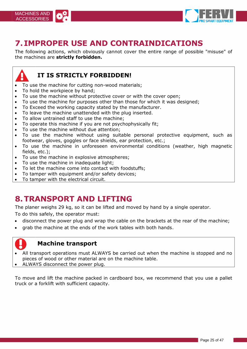
7.IMPROPER USE AND CONTRAINDICATIONSThe following actions, which obviously cannot cover the entire range of possible "misuse" ofthe machines are strictly forbidden.
IT IS STRICTLY FORBIDDEN!
To use the machine for cutting non-wood materials; To hold the workpiece by hand; To use the machine without protective cover or with the cover open; To use the machine for purposes other than those for which it was designed; To Exceed the working capacity stated by the manufacturer. To leave the machine unattended with the plug inserted. To allow untrained staff to use the machine; To operate this machine if you are not psychophysically fit; To use the machine without due attention; To use the machine without using suitable personal protective equipment, such as
footwear, gloves, goggles or face shields, ear protection, etc.; To use the machine in unforeseen environmental conditions (weather, high magnetic
fields, etc.); To use the machine in explosive atmospheres; To use the machine in inadequate light; To let the machine come into contact with foodstuffs; To tamper with equipment and/or safety devices; To tamper with the electrical circuit.
8.TRANSPORT AND LIFTINGThe planer weighs 29 kg, so it can be lifted and moved by hand by a single operator.
To do this safely, the operator must:
disconnect the power plug and wrap the cable on the brackets at the rear of the machine;
grab the machine at the ends of the work tables with both hands.
Machine transport
All transport operations must ALWAYS be carried out when the machine is stopped and nopieces of wood or other material are on the machine table.
ALWAYS disconnect the power plug.
To move and lift the machine packed in cardboard box, we recommend that you use a pallettruck or a forklift with sufficient capacity.

MACHINES ANDACCESSORIES
Page 26 of 47
9.INSTALLATION AND COMMISSIONING
9.1 Machine delivery and unpackingThe planer is delivered packed inside a cardboard box.
Each box contains:
Figure 12 – contents of the package Art. 0686/200.
Art. z
Description Quantity
Combined planing machine Art. 0686/200 1
Casing with suction nozzle – both lipping and thickness planer 1
Thickness adjustment knob – “thickness” planer 1
Allen wrench (4 mm) 1
Workpiece pusher 1
Lateral Guide 1
Belt drive (spare) 2
User's manual / Declaration of conformity 1/1
Before disposing of packing, check no parts of the machine, including the user manual orother documentation, are thrown away.
Also, make sure that at the time of unpacking, the machine is in perfect condition.
The manufacturer is not liable for any defects or missing parts five days afterdelivery.

MACHINES ANDACCESSORIES
Page 27 of 47
Standard packing
The packing materials (plastic bags, polystyrene,cardboard, etc.) must not be left within reach of childrenas a source of potential danger.
Respect the environment! Dispose of the packaging inaccordance with current legislation.
Machine parts that are not varnished are protected by a "protective layer" applied by themanufacturer. Use a cloth moistened with alcohol, rub and clean surfaces thoroughly toremove it.
9.2 AssemblyThe Planer comes almost completely assembled. The only parts that must be mounted on themachine are:
the thickness adjustment crank;
the lateral guide (only for the lipping planer).
To mount the crank, insert the PIN and press it to the bottom, as shown in Figure 13
Figure 13 – Installing the crank.
See paragraph 10.3 of this manual to assemble the lateral guide when using the machine asa lipping planer.
9.3 Positioning
Loss of stability
Place the Planer on a solid and durable surface, such as a workbench, to prevent it fromtipping and causing vibrations.
Before performing any type of work, place the Planer on a flat surface that can withstand theweight and vibrations of the machine during operation.
The planer is equipped with four rubber support feet (see Figure 14), in order to reducevibration of the machine during operation.

MACHINES ANDACCESSORIES
Page 28 of 47
Figure 14 –Planer support stand.
9.4 Electrical connection
Voltage
Before connecting the machine to the mains, check that the voltage corresponds to thatprovided by the manufacturer.
1. Insert the power plug into a grounded bipolar wall socket (230 V AC).
2. Start the machine by pressing the green on switch (see section 10.2) and make surethat the direction of rotation of the cutterhead complies with that indicated by thearrow printed on the protective casing.
3. Before you begin, check the planing shaft and the other rotating parts as follows:
making them turn blank for at least 5 minutes at a speed of operation;
without the presence of staff.

MACHINES ANDACCESSORIES
Page 29 of 47
10. OPERATION
10.1Precautions for use
Using the Machine
The Planer must be used exclusively to work on wooden planks.
Risk of injury
Before using the machine: Make sure it is positioned correctly; Check that all guards are correctly positioned and fastened; Wear appropriate personal protective equipment (PPE) such as gloves, goggles, overalls or
apron and shoes.
10.2Starting/Stopping
To start the Planer, press the green button, markedwith the symbol (I), as shown in Figure 15.
By pressing this button, the electric motor is poweredand placed in the cutterhead rotation that draggrooved roller
Figure 15 – switching on of thePlaner.
Conversely, to stop the Planer, press the red button,marked with the symbol (0), as shown in Figure 16.
By pressing this button, the power supply to theelectric motor is cut off and the cutterhead and theother rotating parts stop.
Figure 16 – stopping the Planer.
Risk of injury
After pressing the stop switch (0), the tree continues to rotate by inertia for a few moments.
Do not hold body parts near moving blades

MACHINES ANDACCESSORIES
Page 30 of 47
Direction of rotation of the tool
The Planer is dangerous if the cutterhead rotates in the opposite direction to that intended bythe manufacturer.
Always check the direction of rotation by starting the machine for a short time.
10.3How to configure the lipping planer
Risk of injury
Before carrying out any planer adjustment, MAKE SURE that the machine is completelySTOPPED by cutting off the power supply.
To configure the Planer (Art. 0686/200)for the lipping planer:
1. Insert the casing//chip exhaust manifoldunder the working table, as shown inFigure 17.
Figure 17 – inserting carter under the table.
2. Pull out both bayonet couplings on the casing/collector and align the outside edges of thecrankcase and working table, as shown in Figure 18.
Figure 18 – extraction of bayonet couplings.
The edges of the sheltermust be in line with theedges of the working table

MACHINES ANDACCESSORIES
Page 31 of 47
3. Insert the two bayonet inserts inside the slits carved on the side edge of the table, asshown in Figure 19.
Figure 19 – insertion of bayonet couplings.
Insertion of grafts
ALWAYS check the correct insertion of both bayonet couplings before starting up themachine.
Both couplings should be inserted completely!
4. Lift the work platform completely, turning the handle (18) clockwise, in order to constrainthe casing/manifold between the bottom edge of the table and the top edge of theplatform itself. See Figure 20.
Figure 20 – Carter in the correct position under the working table.
5. Mount the lateral guide next to the working table. In this regard:
Insert the pin below the lateral guide support into the reference hole on the frame ofthe machine;

MACHINES ANDACCESSORIES
Page 32 of 47
push the guide to the right, in order to align the slot on the mounting bracket with thehole on the table;
attach the guide in place using the screws and washers supplied. To do this, use anAllen wrench as shown in Figure 21.
Figure 21 – Attaching the lateral guide.
To complete the configuration of the Planer. Art. 0686/200 for lipping planing, proceed asdescribed in the following pages of this manual.
Complete the Setup for lipping planing as follows:
Adjust the position of the cutterhead guard. To do this:
Unlock the knob (16), by unscrewing counterclockwise;
Pull the cover, sliding it outwards as shown in Figure 22.
Lock the guard into place by tightening the knob (16).
Figure 22 – adjust the cutterhead guard.
Adjusting and fixing guards
To work safely adjust properly and secure the “bridged” guard of the cutterhead.
The shelter should be adjusted according to the height and width of the planks.

MACHINES ANDACCESSORIES
Page 33 of 47
Adjust the planing thickness, i.e. set the height of thework table, by rotating the knob (19) as depicted inFigure 23:
Turn the knob (19) counterclockwise to lower the tablei.e. to increase the planning thickness;
Conversely, rotate the knob (19) clockwise to raise thetable i.e. to decrease planing thickness.
Figure 23 – Thickness adjustment
10.4Configuration for " thickness" planing
Risk of injury
Before adjusting the Planer, MAKE SURE that the machine is completely STOPPED by turningoff the power supply.
Proceed as follows to configure the Planer Art. 0686/200 for "thickness" planing:
1 If you previously configured it to perform lipping planing, remove the lateral guide.
Removing the lateral guide
If necessary, disassemble the lateral guide on the side of the work table, performing theoperations described in paragraph 10.3.
2 Adjust the position of the cutter block guard so that the entire cuttershaft (and theblades), is completely uncovered. In this regard:
Unlock the knob (16), by unscrewing it counterclockwise;
Pull the cover, sliding it outwards along its entire length, in order to "take it out" ofthe work table, as shown in Figure 24.
Lock the cover into place by tightening the knob (16).
Figure 24 – Casing in the correct position for the "thickness" configuration
MACHINES ANDACCESSORIES
Page 34 of 47
3 If it was previously configured for lipping planing, remove the casing/collector fromunder the table.
Casing/collector disassembly
If necessary, disassemble the casing/collector under the work table, performing theoperations described in paragraph 10.3 inversely.
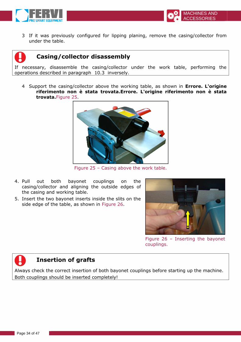
4 Support the casing/collector above the working table, as shown in Errore. L'origineriferimento non è stata trovata.Errore. L'origine riferimento non è statatrovata.Figure 25.
Figure 25 – Casing above the work table.
4. Pull out both bayonet couplings on thecasing/collector and aligning the outside edges ofthe casing and working table.
5. Insert the two bayonet inserts inside the slits on theside edge of the table, as shown in Figure 26.
Figure 26 – Inserting the bayonetcouplings.
Insertion of grafts
Always check the correct insertion of both bayonet couplings before starting up the machine.
Both couplings should be inserted completely!

MACHINES ANDACCESSORIES
Page 35 of 47
6. Adjust the planing thickness, i.e. set the height ofthe work platform, by turning the handle (18). SeeFigure Figure 27.
Turn the crank (18) anticlockwise to lower theplatform to increase planning thickness;
Conversely, turn the crank (18) clockwise toraise the platform i.e. to decrease planingthickness.
Figure 27 – Thickness adjustment
Chips and sawdust suction
In any case, whatever the configuration of the machine before starting to work, alwaysconnect a vacuum cleaner to the crankcase vent/exhaust manifold.
It is forbidden to operate without having connected the device to the Planer!
10.5How to perform safe planing
10.5.1 Surface planing
Keeping the guard against the output table, bring theguard against the guide with your left hand, then lift itup according to the thickness of the workpiece.
Push the piece just below the guard with your righthand and place the latter on the workpiece (see Figure28).
Figure 28 – Adjustment of theguard.
With your hands on the workpiece guide it to the inputtable and then slip it over the guard or move it furtherwith one hand (as shown in Figure 29).
As soon as possible keep guiding the workpiece withboth hands onto the output piece.
This technique can be implemented with reducedthickness workpieces.
Figure 29 – Surface planing.

MACHINES ANDACCESSORIES
Page 36 of 47
10.5.2 Lipping planing
Place the workpiece against the guide and guide it withthe right hand approximately up to the entry side of thelip of the input table.
Push the guard with your left hand against theworkpiece. The guard should be based on the outputtable (see Figure 30).
Figure 30 – Guard adjustment
With the left hand, for example with clenched fist withthe thumb against the piece, press and hold theworkpiece against the output table. Advance the pieceregularly with the right hand, for example with aclenched fist with your thumb on the piece (see Figure31).
This technique can be implemented with reducedthickness workpieces.
Figure 31 – Lip planing.
10.5.3 Planing pieces of greater thickness
Rest the guard on the table and adjust it horizontallyon the width of the workpiece.
Align the workpiece against the guide with your handsresting on the workpiece at the side of the guard (seeFigure 32).
Advance the workpiece with both hands. In this actionthe left hand, for example, a clenched fist, push theworkpiece against the table and help out. Res the righthand on the workpiece.
Figure 32 – Planing thicker pieces.

MACHINES ANDACCESSORIES
Page 37 of 47
10.5.4 Planing short workpieces
Push the workpiece on the table with the palm of yourhand and advance it holding the block-piece with yourright hand. Slide your left hand on the guard or bringyour left hand beyond it and as soon as the piece restson the output table move the pressure on the left handon the output table (see Figure 33)
The block-piece should not be thicker than theworkpiece.
Figure 33 – Planing shortworkpieces
10.5.5 Planing with 45° inclined guide
Rest the workpiece with your right hand against theinclined guide.
Press the guard horizontally with your left hand so thatit just touches the workpiece and tighten the lockinglever with your right hand. This way the shelter is stucksideways and the workpiece cannot slip out of theguide (see Figure 34).
Figure 34 – Adjusting the guard.
Keep the workpiece pressed against the outout tableand with the left hand clenched into a fist push itforward with the right hand closed (see Figure 35).
Figure 35 – Planing with 45°inclined guide.
10.5.6 Strip planing
Adjust the guard as for surface planing, and pay particular attention while pushing theworkpiece.
Risk of injury
With strip planing, pay particular attention while pushing the workpiece.

MACHINES ANDACCESSORIES
Page 38 of 47
10.5.7 Thicknessing
Follow the procedure below to obtain the correct planning thickness(see Figure 36):
1. Position the workpiece on the work platform for "thickness" planing, with the unworkedside facing upwards.
2. Lift the platform in relation to the workpiece.
3. Adjust chip removal up to a maximum of 2 mm using the handle (18).
4. Switch on the machine and push the workpiece forward (see Figure 36).
Figure 36 – Thickness planning.
The pieces with the ends shaped differently should always be inserted by the biggest side.When planing wood with knots, we recommend covering the thickness table with paraffinwax, to make its movement smoother.
11. MAINTENANCEAny maintenance, except for that specifically listed in this manual should be performed byqualified staff authorized by the manufacturer.
This manual does not elaborate information on disassembly and maintenance, as theseoperations should always be carried out exclusively by Technical Assistance staff.
11.1Ordinary maintenance
11.1.1 Routine at the end of each processing
Electric shock
Before maintenance or checks, turn off the machine and ALWAYS unplug the plug from thepower outlet to avoid the risk of electric shock.
Regularly clean and take care of this machine to ensure perfect efficiency and durability.
Use a compressor to blow off shavings, chips and sawdust accumulating inside the machineand on work surfaces at the end of each machining operation

MACHINES ANDACCESSORIES
Page 39 of 47
Working with compressed air
ALWAYS wear goggles when using compressed air.
Check the state of the Planer and CE plate and warning plate at the same time; If they are nolonger legible ask for more.
Faults or defects
Disable the machine and affix a warning sign to forbid its use, until it works properly againand it is safe to use.
Cleaning the machine
DO NOT use detergents or solvents; the plastic parts are easily attacked by chemical agents.
11.2PeriodicallyEvery 6 months of the machine’s life, perform a thorough inspection of operation and wear.
Disconnect the plug from the mains and check the length and the efficiency of the electricmotor brushes. If necessary, replace them with identical ones.
11.3LubrificationThe machine is lubricated by the manufacturer.
The electric motor does not require maintenance (sealed bearings).
The wood feed rollers tend to get dirty working resin softwoods. Therefore, the rollers andbearing seats must always be kept clean.
The surfaces of the plates must always be sprayed with products that make them slippery toslide the work pieces better.
We recommend not using fat as it tends to blend in with the wood waste and makes themovements harder.
Approximately every 10 hours of use, we recommend lubricating the following parts:
The bearings of the workpiece feed rollers;
Pulley bearings and transmission gears;
Workpiece feed roller transmission chain;
To lubricate these moving components, proceed as follows:
1. Remove the front guard, after unscrewing the 3 fastening nuts;
2. Lubricate the bearings and chain with lubricant (Figure 37).

MACHINES ANDACCESSORIES
Page 40 of 47
After work is finished, replace the cover and fasten it using the 3 fixing nuts.
Figure 37 – Thickness planing.
Lubricate the headless screws for height adjustment of the working platform onlywith dry lubricants.
11.4Checking/replacing the drive belts
To check the tension of the drive belts:
1. Remove the front guard, after unscrewing the 3 fastening nuts;
2. Check the tension of the drive belts pressing them down in the middle (between the twopulleys) and checking the transverse gauge of these belts (maximum sag).
They need to be replaced if the gauge is greater than 5/6 mm.
To replace the drive belts, proceed as follows:
1. Remove the front guard, after unscrewing the 3 fastening nuts;
2. Unscrew the 4 fixing nuts of the drive pulley and loosen the belts using the fixing holes ofthe pulley support;
3. remove the worn belt and replace it with an identical one or the same type;
4. Re-tension the belt by moving the drive pulley on the opposite side to that conducted byexploiting the fixing holes of the pulley bracket then attach the bracket by tightening the4 mounting bolts.
5. Check the tension of the drive belts by pressing down in the middle (between the twopulleys) and checking the transverse gauge of the same belts.
After work is finished, replace the cover and fasten it using the 3 fastening nuts.

MACHINES ANDACCESSORIES
Page 41 of 47
11.5Replacing the cutting blades
The blades of the planer must be marked with the name or logo of the manufacturer andshould indicate the maximum rotation allowed.
1. Unscrew the 3 screws from the blade using the appropriate key;
2. Remove the blade and blade pusher and clean the surface;
3. Clean the blade very carefully so as not to cut yourself.
4. Insert the new blade and blade pusher so that it protrudes on the surface of the shaftup to 1.1 mm, and then tighten the 3 blade fastening screws.
The manufacturer recommends that the blade should protrude from 0.7 to 0.8 mm.
Repeat the procedure for the replacement of the second blade.
After completing all the steps mentioned above, make sure that all locking screws for eachblade are in the right position and well-tightened, then secure all protective covers; try toturn on the machine by pressing the start button.
12. DISPOSAL OF COMPONENTS AND MATERIALSIf the machine is to be scrapped, dispose of its components by separate collection.
Respect the Environment!
Contact a specialist centre for the collection of metallic materials.
In this regard, divide the materials according to their nature, with the assistance of specialistcompanies authorized for waste disposal, in compliance with the requirements of the law.
Respect the Environment!
Dispose of tailings (shavings, sawdust, etc.) in compliance with current legislation.

MACHINES ANDACCESSORIES
Page 42 of 47
13. TROUBLESHOOTING
PROBLEM PROBABLE CAUSE SOLUTION
Noisy operation
A) Non-lubricated bearings.
B) Rubbing the blades.
C) Blade friction
D) Loose blades.
A) Contact Technical Assistance.
B) Lubricate.
C) Remove/replace the blades andcheck for scrolling.
D) Tighten the screws of the blades.
The motor will notstart.
A) Electrical power supply.
B) Electrical connections.
C) Burnt motor windings.
D) Blown fuses.
E) Broken switch.
A) Check the power cord.
B) Check the electrical connections.
C) Contact Technical Support.
D) Replace the fuses.
E) Contact Technical Support.
Poor cuttingefficiency oroverheating of theblades.
A) Excessive pressure onthe workpiece.
B) Worn blades or that donot cut well.
C) Material too hard.
A) Apply less pressure.
B) Check the sharpness and wear ofthe blades.
C) Lubricate while you work.

MACHINES ANDACCESSORIES
Page 43 of 47
14. ELECTRIC CIRCUIT

MACHINES ANDACCESSORIES
Page 44 of 47
15. REPLACEMENT PARTS

MACHINES ANDACCESSORIES
Page 45 of 47
Reference n. Description Reference n. Description
0686/200/01 Bolt 0686/200/42 Cable bracket
0686/200/02 Cable wrap 0686/200/43 Rubber bearing
0686/200/03 Side guard 0686/200/44 Flat belt
0686/200/04 Bolt 0686/200/45 Washer
0686/200/05 Split washer 0686/200/46 Split washer
0686/200/06 Rubber bearing 0686/200/47 Bolt
0686/200/06-01 Hex nut 0686/200/48 Rod II
0686/200/07 Motor protection 0686/200/49 Washer
0686/200/08 Bolt 0686/200/50 Bolt
0686/200/09 Nut 0686/200/51 Line
0686/200/10 Nut 0686/200/52 Plastic locking nut
0686/200/11 Split washer 0686/200/53 Protective grommet
0686/200/12 Washer 0686/200/54 Nut
0686/200/13 Conical ring 0686/200/54-01 Washer
0686/200/14 Screw 0686/200/54-02 Spring
0686/200/15 Chain 0686/200/54-03 Rod
0686/200/16 Crank 0686/200/54-04 Screw
0686/200/17 Cap 0686/200/54-05 Scale
0686/200/18 Short threaded pin 0686/200/54-06 Screw
0686/200/19 Table 0686/200/55 Line lock
0686/200/19-01 Threaded pin, nut 0686/200/56 Rubber bearing
0686/200/19-02 Sleeve coupling 0686/200/57 Power cord
0686/200/20 Pointer 0686/200/58 Protective cap
0686/200/21 Split washer 0686/200/59 Switch box
0686/200/22 Washer 0686/200/60 Bolt
0686/200/23 Bolt 0686/200/61 Thermal protector
0686/200/24 Chain sprocket 0686/200/62 Bolt
0686/200/25 Washer 0686/200/63 Bolt
0686/200/26 Split washer 0686/200/64 Bolt
0686/200/27 Hex nut 0686/200/65 Terminal
0686/200/28 Bolt 0686/200/66 Switches
0686/200/29 Sleeve coupling 0686/200/67 Nut
0686/200/30 Bolt 0686/200/68 Split ring
0686/200/31 Left lateral guard 0686/200/69 Washer
0686/200/32 Cutting depth scale 0686/200/70 Chain sprocket
0686/200/33 Bolt 0686/200/71 Square sleeve
0686/200/34 Split washer 0686/200/72 Sprocket
0686/200/35 Washer 0686/200/73 Split ring
0686/200/36 Washer 0686/200/74 Pulley
0686/200/37 Split washer 0686/200/75 Plate

MACHINES ANDACCESSORIES
Page 46 of 47
0686/200/38 Hex nut 0686/200/76 Spring
0686/200/39 Nut 0686/200/77 Shaft
0686/200/40 Rod 0686/200/78 Bolt
0686/200/41 Bolt 0686/200/79 Split washer
Reference n. Description Reference n. Description
0686/200/80 Washer 0686/200/125 Headless screw
0686/200/81 Chain sprocket 0686/200/126 Lid
0686/200/82 Chain 0686/200/127 Square tube
0686/200/83 Belt drive0686/200/127-01
Lid
0686/200/84 Bolt 0686/200/128 Spacer
0686/200/85 Bolt0686/200/128-01
Split ring
0686/200/86 Flat belt0686/200/128-02
Split ring
0686/200/87 Support plate 0686/200/129 Knob
0686/200/88 Pole 0686/200/130 Bolt
0686/200/89 Bolt 0686/200/131 Micro switch
0686/200/90 Split washer 0686/200/132 Switch cover
0686/200/91 Drive pulley0686/200/132-01
Washer
0686/200/92 Motor0686/200/132-02
Bolt
0686/200/93 Ball bearing 0686/200/133 Headless screw
0686/200/94 Bearing cover 0686/200/134 Stem
0686/200/95 Split washer0686/200/134-01
Washer
0686/200/96 Hex nut0686/200/134-02
Hex nut
0686/200/97 Strut 0686/200/135 Long headless screw
0686/200/98 Washer 0686/200/136 Hex nut
0686/200/99 Bolt 0686/200/137 Split washer
0686/200/100 Feed roller 0686/200/138 Washer
0686/200/101 Anti-expulsion 0686/200/139 Rear table
0686/200/102 Feed roller 0686/200/140 Blade guard
0686/200/103/116 Springs 0686/200/141 Pin
0686/200/104 Bearing bushing 0686/200/142 Short stem
0686/200/105 Rod 0686/200/143 Angle adjustment 1
0686/200/106 Washer 0686/200/144 Angle adjustment 2
0686/200/107 Anti-expulsion 0686/200/145 Nut
0686/200/108 Bolt 0686/200/146 Bolt
0686/200/109 Blade locking device 0686/200/147 Tapered shank
0686/200/110 Blades 0686/200/148 Bolt

MACHINES ANDACCESSORIES
Page 47 of 47
0686/200/111 Blade support 0686/200/149 Knob
0686/200/111-01 Bolt 0686/200/150 Guide support
0686/200/111-02 Shaft 0686/200/151 Long stem
0686/200/112 Bolt 0686/200/152 Lateral guide
0686/200/113 Roller bearing 0686/200/153 Hanger clamp
0686/200/114 Bearing cover 0686/200/154 Washer
0686/200/115 Blade baffle plate 0686/200/155 Split washer
0686/200/117 Plastic pointer 0686/200/156 Bolt
0686/200/118 Front table 0686/200/157 Intake manifold
0686/200/119 Sliding blocks 0686/200/158 Key
0686/200/120 Bolt 0686/200/159 Lid
0686/200/121 Knob 0686/200/160 Bolt
0686/200/122 protection arch 0686/200/161 Push-piece lever
0686/200/123 Knob 0686/200/162 Allen wrench
0686/200/124 Scale
Related Documents


