Use or disclosure of the information contained herein is subject to the restrictions on the cover page. F-35 Program Information Non-Export Controlled Information LMMST REL TO F-35 Program © 2014 Lockheed Martin Corporation Luke AFB FMS Layer 1 Network Approach October 18, 2014

Use or disclosure of the information contained herein is subject to the restrictions on the cover page. F-35 Program Information Non-Export Controlled.
Dec 24, 2015
Welcome message from author
This document is posted to help you gain knowledge. Please leave a comment to let me know what you think about it! Share it to your friends and learn new things together.
Transcript
Use or disclosure of the information contained herein is subject to the restrictions on the cover page.
F-35 Program Information
Non-Export Controlled Information
LMMST REL TO F-35 Program
© 2014 Lockheed Martin Corporation
Luke AFB FMSLayer 1 Network Approach
October 18, 2014
Use or disclosure of the information contained herein is subject to the restrictions on the cover page.
F-35 Program Information
Non-Export Controlled Information
LMMST REL TO F-35 Program
© 2014 Lockheed Martin Corporation
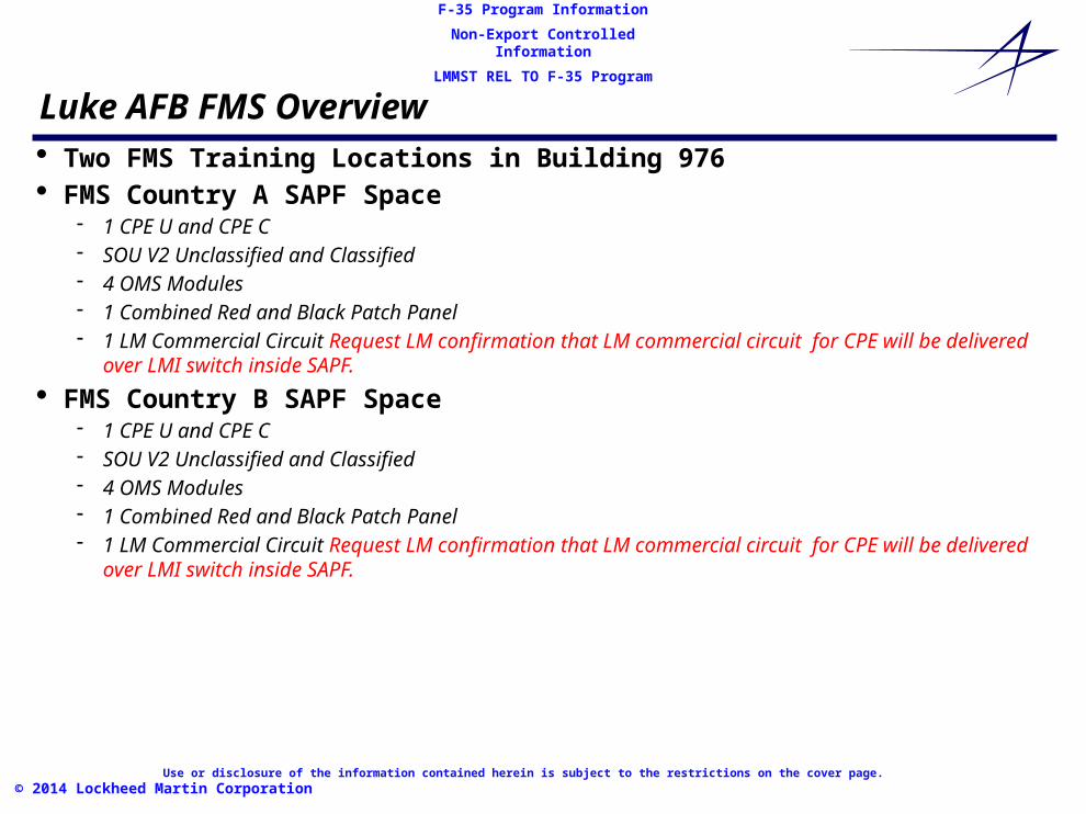
Luke AFB FMS Overview· Two FMS Training Locations in Building 976· FMS Country A SAPF Space
- 1 CPE U and CPE C- SOU V2 Unclassified and Classified- 4 OMS Modules- 1 Combined Red and Black Patch Panel- 1 LM Commercial Circuit Request LM confirmation that LM commercial circuit for CPE will be
delivered over LMI switch inside SAPF.
· FMS Country B SAPF Space- 1 CPE U and CPE C- SOU V2 Unclassified and Classified- 4 OMS Modules- 1 Combined Red and Black Patch Panel- 1 LM Commercial Circuit Request LM confirmation that LM commercial circuit for CPE will be
delivered over LMI switch inside SAPF.
Use or disclosure of the information contained herein is subject to the restrictions on the cover page.
F-35 Program Information
Non-Export Controlled Information
LMMST REL TO F-35 Program
© 2014 Lockheed Martin Corporation
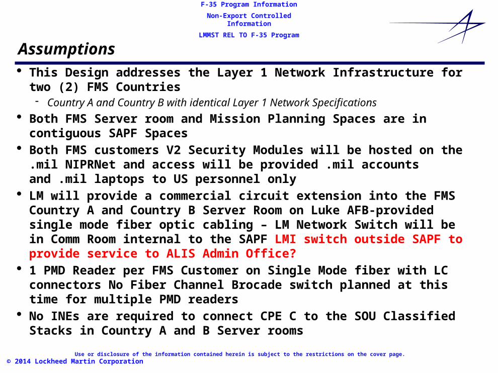
Assumptions· This Design addresses the Layer 1 Network Infrastructure for two (2) FMS
Countries- Country A and Country B with identical Layer 1 Network Specifications
· Both FMS Server room and Mission Planning Spaces are in contiguous SAPF Spaces
· Both FMS customers V2 Security Modules will be hosted on the .mil NIPRNet and access will be provided .mil accounts and .mil laptops to US personnel only
· LM will provide a commercial circuit extension into the FMS Country A and Country B Server Room on Luke AFB-provided single mode fiber optic cabling – LM Network Switch will be in Comm Room internal to the SAPF LMI switch outside SAPF to provide service to ALIS Admin Office?
· 1 PMD Reader per FMS Customer on Single Mode fiber with LC connectors No Fiber Channel Brocade switch planned at this time for multiple PMD readers
· No INEs are required to connect CPE C to the SOU Classified Stacks in Country A and B Server rooms
Use or disclosure of the information contained herein is subject to the restrictions on the cover page.
F-35 Program Information
Non-Export Controlled Information
LMMST REL TO F-35 Program
© 2014 Lockheed Martin Corporation
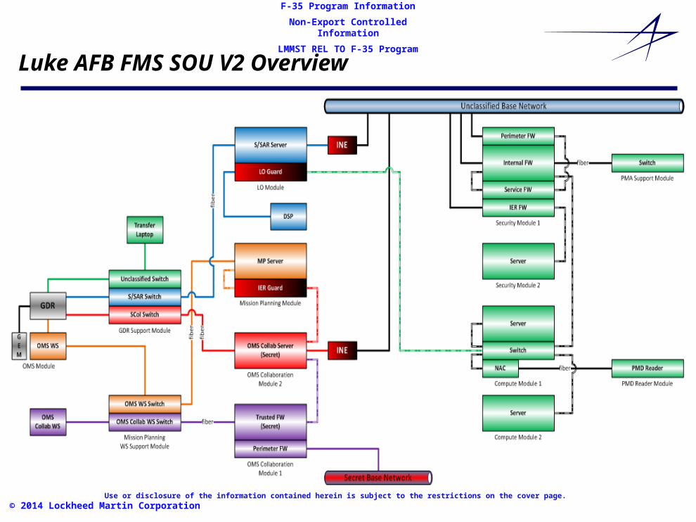
Luke AFB FMS SOU V2 Overview
Use or disclosure of the information contained herein is subject to the restrictions on the cover page.
F-35 Program Information
Non-Export Controlled Information
LMMST REL TO F-35 Program
© 2014 Lockheed Martin Corporation
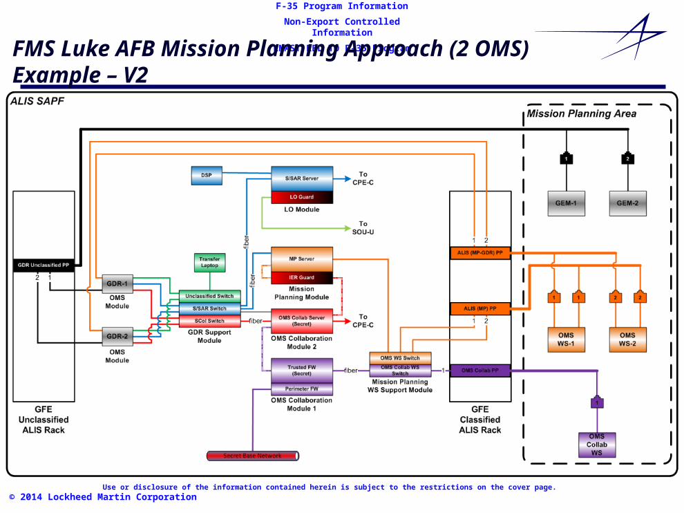
FMS Luke AFB Mission Planning Approach (2 OMS)Example – V2

Use or disclosure of the information contained herein is subject to the restrictions on the cover page.
F-35 Program Information
Non-Export Controlled Information
LMMST REL TO F-35 Program
© 2014 Lockheed Martin Corporation
FMS Country A and B Dual Server Room and Mission Planning Areas Server Room Configurations
Use or disclosure of the information contained herein is subject to the restrictions on the cover page.
F-35 Program Information
Non-Export Controlled Information
LMMST REL TO F-35 Program
© 2014 Lockheed Martin Corporation
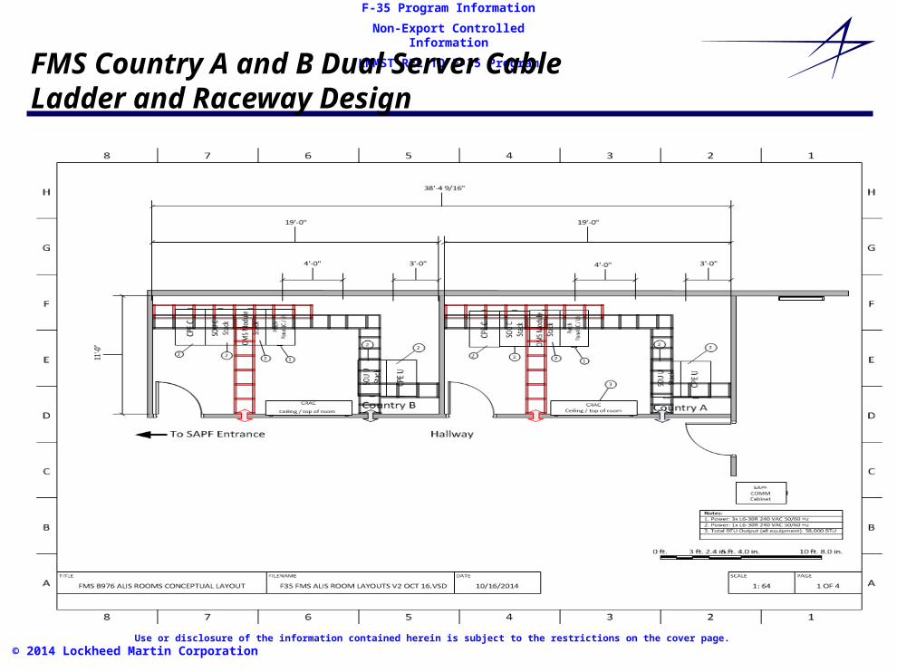
FMS Country A and B Dual Server Cable Ladder and Raceway Design

Use or disclosure of the information contained herein is subject to the restrictions on the cover page.
F-35 Program Information
Non-Export Controlled Information
LMMST REL TO F-35 Program
© 2014 Lockheed Martin Corporation
FMS Country A and B Dual Server Room and Mission Planning SAPF Cabling Layout
Use or disclosure of the information contained herein is subject to the restrictions on the cover page.
F-35 Program Information
Non-Export Controlled Information
LMMST REL TO F-35 Program
© 2014 Lockheed Martin Corporation
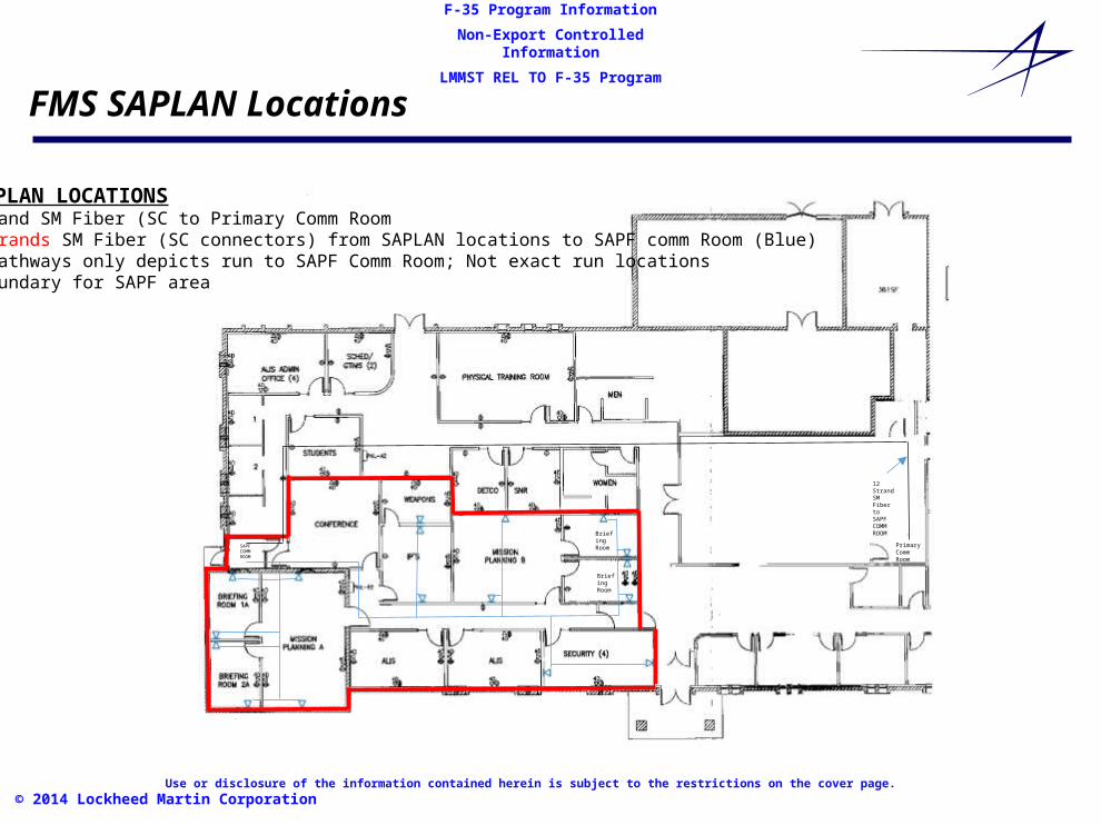
FMS SAPLAN Locations
SAPF COMMROOM
Briefing Room
Briefing Room
PrimaryCommRoom
12 StrandSM Fiber to SAPF COMM ROOM
SAPF SAPLAN LOCATIONSA. 12 Strand SM Fiber (SC to Primary Comm RoomB. Two strands SM Fiber (SC connectors) from SAPLAN locations to SAPF comm Room (Blue)C. Blue pathways only depicts run to SAPF Comm Room; Not exact run locationsD. Red boundary for SAPF area
Use or disclosure of the information contained herein is subject to the restrictions on the cover page.
F-35 Program Information
Non-Export Controlled Information
LMMST REL TO F-35 Program
© 2014 Lockheed Martin Corporation
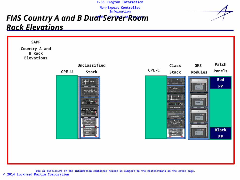
FMS Country A and B Dual Server RoomRack Elevations
SAPF
Country A and B Rack Elevations
Unclassified
Stack
Class
Stack
OMS
ModulesCPE-U
Red
PP
Black
PP
CPE-C
Patch
Panels
Use or disclosure of the information contained herein is subject to the restrictions on the cover page.
F-35 Program Information
Non-Export Controlled Information
LMMST REL TO F-35 Program
© 2014 Lockheed Martin Corporation
FMS Country A V2 Anticipated Squadron Server Room Equipment· Luke AFB FMS Country A network diagrams are notional and do not show
red/black separation requirements· Not all ALIS equipment that will be delivered is depicted
- Illustrating· 1 SOU-U V2
- Security Module- Compute Module- UPS Module- UPS Battery Extension- 1 PMD Reader
· 1 SOU-C V2- 1 DSP/UPS Module- 4 OMS Module (OMS W/S, GEMR, and GDR)- 1 OMS Collaboration Module- 1 Mission Planning Module- 1 GDR Support Module- 1 LO Module- 1 OMS Collaboration W/S
· The GFE ALIS Network Rack is 1 rack with red/black separation

Use or disclosure of the information contained herein is subject to the restrictions on the cover page.
F-35 Program Information
Non-Export Controlled Information
LMMST REL TO F-35 Program
© 2014 Lockheed Martin Corporation
FMS Country ASOU-U/C V2 External Layer-1 Connectivity
Use or disclosure of the information contained herein is subject to the restrictions on the cover page.
F-35 Program Information
Non-Export Controlled Information
LMMST REL TO F-35 Program
© 2014 Lockheed Martin Corporation
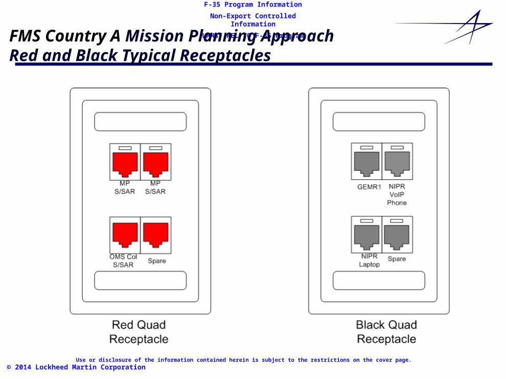
FMS Country A Mission Planning Approach Red and Black Typical Receptacles
Use or disclosure of the information contained herein is subject to the restrictions on the cover page.
F-35 Program Information
Non-Export Controlled Information
LMMST REL TO F-35 Program
© 2014 Lockheed Martin Corporation
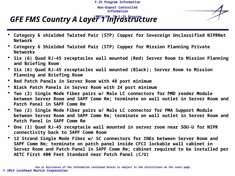
GFE FMS Country A Layer 1 infrastructure
· Category 6 shielded Twisted Pair (STP) Copper for Sovereign Unclassified NIPRNet Network · Category 6 Shielded Twisted Pair (STP) Copper for Mission Planning Private Networks· Six (6) Quad RJ-45 receptacles wall mounted (Red) Server Room to Mission Planning and Briefing
Room· Six (6) Quad RJ-45 receptacles wall mounted (Black); Server Room to Mission Planning and Briefing
Room· Red Patch Panels in Server Room with 48 port minimum· Black Patch Panels in Server Room with 24 port minimum· Two (2) Single Mode Fiber pairs w/ Male LC connectors for PMD reader Module between Server Room
and SAPF Comm Rm; terminate on wall outlet in Server Room and Patch Panel in SAPF Comm Rm· Two (2) Single Mode Fiber pairs w/ Male LC connector for PMA Support Module between Server Room
and SAPF Comm Rm; terminate on wall outlet in Server Room and Patch Panel in SAPF Comm Rm· One (1) Quad RJ-45 receptacle wall mounted in server room near SOU-U for NIPR connectivity back to
SAPF Comm Room· 12 Strand Single Mode Fiber w/ SC connectors for INEs between Server Room and SAPF Comm Rm;
terminate on patch panel inside CFCI lockable wall cabinet in Server Room and Patch Panel in SAPF Comm Rm; cabinet required to be installed per AETC First 400 Feet Standard near Patch Panel (C/U)
Use or disclosure of the information contained herein is subject to the restrictions on the cover page.
F-35 Program Information
Non-Export Controlled Information
LMMST REL TO F-35 Program
© 2014 Lockheed Martin Corporation
GFE FMS Country A Layer 1 infrastructureRecommended Cable Patch Cord Colors· Secret SAR Blue · Secret Collateral Purple · Mission Planning/SSAR Orange · ALIS Unclassified Green· ALIS PMD Green· NIPRNet Gray

Use or disclosure of the information contained herein is subject to the restrictions on the cover page.
F-35 Program Information
Non-Export Controlled Information
LMMST REL TO F-35 Program
© 2014 Lockheed Martin Corporation
Black FMS Country A Layer 1 SOU V2· Black Patch Panel
• 24 RJ-45 Patch Field Density· Black Work Area Receptacles
• 6 4-port (quad) RJ-45 Work Area Wall Mounted Receptacle· Black shielded Twisted Pair (TP) CAT 6 Cable Bundle
- Black Patch Panel to 6 Black Receptacles · Amount: 6 Cat 6 Cable Run Total· Lengths: Run from 6 Black Receptacles to the Black Patch Panel in Walls
· shielded Twisted Pair Black CAT 6 Patch Cords- NIPRNet to ALIS Security Module - Amount: 3 Patch Cord Total (Gray)
· Lengths: 20’- Phone drops to be ran back to SAPF Comm Rm; not Server Room. (AETC First 400 Feet)
· Shielded Twisted Pair Black CAT 6 Patch Cords- Black Receptacle to GEM-R (Green)
· Amount: 4 6 patch Cords Total (Green)· Lengths: xx – 10’ GEM-R to Black Receptacle
- Black Patch Panel to GDR (Green)· Amount: 4 6 patch Cords Total (Green)· Lengths: xx – 10’ GDR to Black Patch Panel
- PMD Reader· 1 pair Single Mode Fiber Optic Cable between PMD Reader and the Compute Module Network Access Controller
PMA
1 pair Single Mode Fiber Optic Cable between PMD Reader and the Security Module

Use or disclosure of the information contained herein is subject to the restrictions on the cover page.
F-35 Program Information
Non-Export Controlled Information
LMMST REL TO F-35 Program
© 2014 Lockheed Martin Corporation
Red FMS Country A Layer 1 SOU V2Mission Planning
· Red Patch Panel- 48 RJ-45 Patch Field Density
· Red Work Area Receptacles- 6 4-port (quad) RJ-45 Work Area Wall Mounted Receptacle
· Red Shielded Twisted Pair (STP) CAT 6 Cable Bundle- Red Patch Panel to 4 Red Receptacles
· Amount: 24 Cat 6 STP Cable Run Total run from Red Quad Receptacles to the Red Patch Panel
Use or disclosure of the information contained herein is subject to the restrictions on the cover page.
F-35 Program Information
Non-Export Controlled Information
LMMST REL TO F-35 Program
© 2014 Lockheed Martin Corporation
Red FMS Country A Layer 1 SOU V2 andMission Planning Layer 1 ALIS GFE (w/INEs)
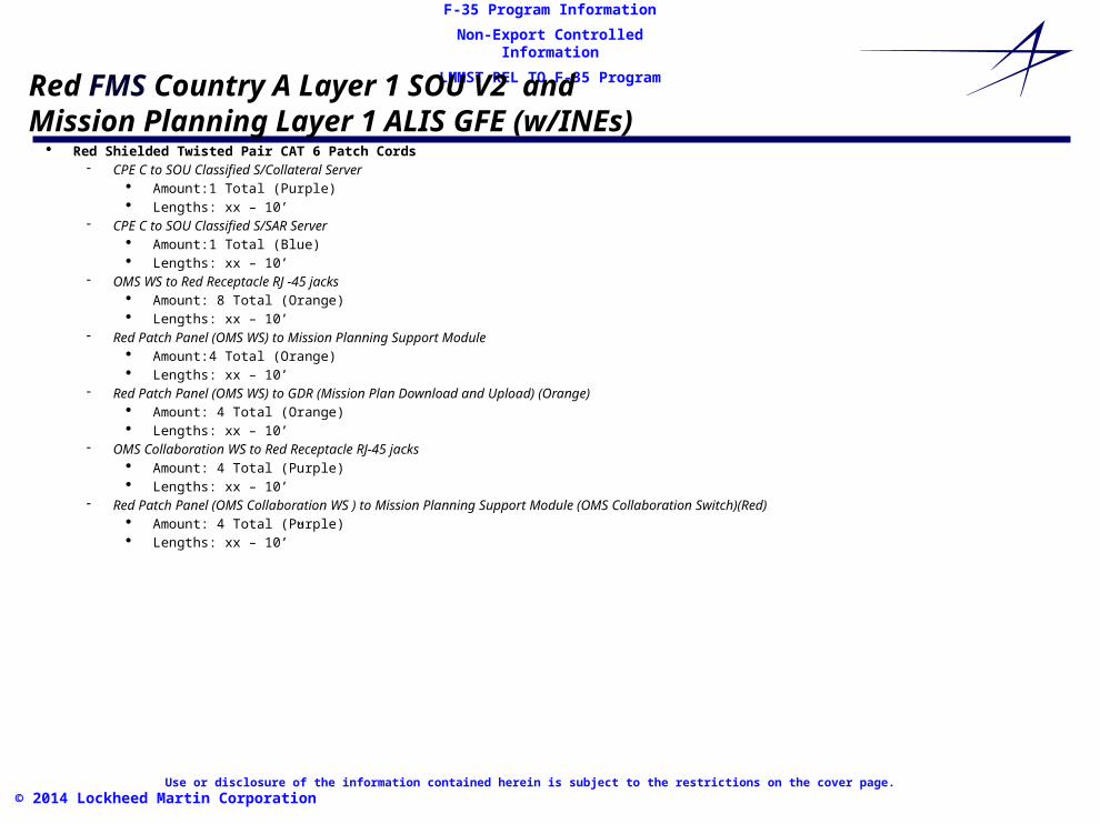
· Red Shielded Twisted Pair CAT 6 Patch Cords- CPE C to SOU Classified S/Collateral Server
· Amount:1 Total (Purple)· Lengths: xx – 10’
- CPE C to SOU Classified S/SAR Server· Amount:1 Total (Blue)· Lengths: xx – 10’
- OMS WS to Red Receptacle RJ -45 jacks· Amount: 8 Total (Orange)· Lengths: xx – 10’
- Red Patch Panel (OMS WS) to Mission Planning Support Module· Amount:4 Total (Orange)· Lengths: xx – 10’
- Red Patch Panel (OMS WS) to GDR (Mission Plan Download and Upload) (Orange)· Amount: 4 Total (Orange)· Lengths: xx – 10’
- OMS Collaboration WS to Red Receptacle RJ-45 jacks· Amount: 4 Total (Purple)· Lengths: xx – 10’
- Red Patch Panel (OMS Collaboration WS ) to Mission Planning Support Module (OMS Collaboration Switch)(Red)· Amount: 4 Total (Purple)· Lengths: xx – 10’”

Use or disclosure of the information contained herein is subject to the restrictions on the cover page.
F-35 Program Information
Non-Export Controlled Information
LMMST REL TO F-35 Program
© 2014 Lockheed Martin Corporation
Red FMS Country A Layer 1 SOU V2 Fiber Optic Module Connections· Single Mode Fiber Optic Cables with LC Connectors
· Mission Planning Support Module to Mission Planning Module· Amount: 1 Total· Lengths: xx – 10’
· Mission Planning Support Module to OMS Collaboration Module 1· Amount: 1 Total· Lengths: xx – 10’
· GDR Support Module to OMS Collaboration Module (S/Collateral Aggregate)· Amount: 1 Total· Lengths: xx – 10’
· GDR Support Module to LO Module Secret SAR Server (S/SAR) Aggregate)· Amount: 1 Total· Lengths: xx – 10’
Use or disclosure of the information contained herein is subject to the restrictions on the cover page.
F-35 Program Information
Non-Export Controlled Information
LMMST REL TO F-35 Program
© 2014 Lockheed Martin Corporation
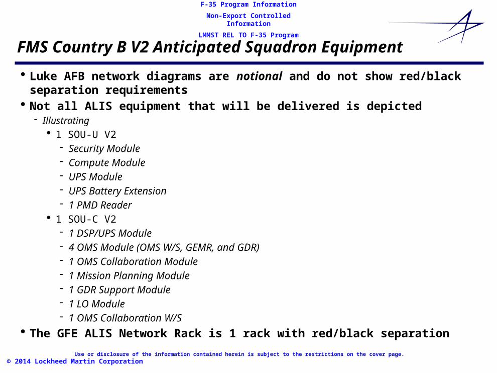
FMS Country B V2 Anticipated Squadron Equipment
· Luke AFB network diagrams are notional and do not show red/black separation requirements
· Not all ALIS equipment that will be delivered is depicted- Illustrating
· 1 SOU-U V2- Security Module- Compute Module- UPS Module- UPS Battery Extension- 1 PMD Reader
· 1 SOU-C V2- 1 DSP/UPS Module- 4 OMS Module (OMS W/S, GEMR, and GDR)- 1 OMS Collaboration Module- 1 Mission Planning Module- 1 GDR Support Module- 1 LO Module- 1 OMS Collaboration W/S
· The GFE ALIS Network Rack is 1 rack with red/black separation
Use or disclosure of the information contained herein is subject to the restrictions on the cover page.
F-35 Program Information
Non-Export Controlled Information
LMMST REL TO F-35 Program
© 2014 Lockheed Martin Corporation
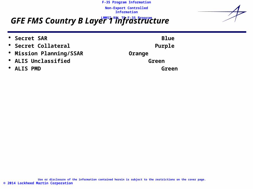
GFE FMS Country B Layer 1 infrastructure
· Secret SAR Blue · Secret Collateral Purple · Mission Planning/SSAR Orange · ALIS Unclassified Green· ALIS PMD Green

Use or disclosure of the information contained herein is subject to the restrictions on the cover page.
F-35 Program Information
Non-Export Controlled Information
LMMST REL TO F-35 Program
© 2014 Lockheed Martin Corporation
Black FMS Country B Layer 1 SOU V2
· Black Patch Panel- 16 RJ-45 Patch Field Density
· Black Work Area Receptacles- 4 4-port (quad) RJ-45 Work Area Wall Mounted Receptacle
· Black Unshielded Twisted Pair (UTP) CAT 6 Cable Bundle- Black Patch Panel to 4 Black Receptacles
· Amount: 16 Cat 6 Cable Run Total· Lengths: Run from 4 Black Receptacles to the Black Patch Panel in Walls
· Unshielded Twisted Pair Black CAT 6 Patch Cords- NIPRNet to ALIS Security Module - Amount: 3 Patch Cord Total (Gray)
· Lengths: 20’- NIPRNet switch to Black Patch Panel for network drops
· Amount: 4 Patch Cord Total (Gray)· Lengths: 10”
- Black Receptacle to NIPRNet Laptop Amount: · Amount: 4 Patch Cord Total (Gray)· Lengths: 10”
- NIPRNet Switch to Black Patch Panel for Phone drops· Amount: 4 Patch Cord Total (Gray)· Lengths: 10”
- Black Receptacle to NIPRNet VoIP Phone· Amount: 12 Patch Cord Total (Gray)
· Shielded Twisted Pair Black CAT 6 Patch Cords- Black Receptacle to GEM-R (Green)
· Amount: 4 patch Cords Total (Green)· Lengths: xx – 10’ GEM-R to Black Receptacle
- Black Patch Panel to GDR (Green)· Amount: 4 patch Cords Total (Green)· Lengths: xx – 10’ GDR to Black Patch Panel
- PMD Reader· 1 pair Single Mode Fiber Optic Cable between PMD Reader and the Compute Module Network Access Controller
Use or disclosure of the information contained herein is subject to the restrictions on the cover page.
F-35 Program Information
Non-Export Controlled Information
LMMST REL TO F-35 Program
© 2014 Lockheed Martin Corporation
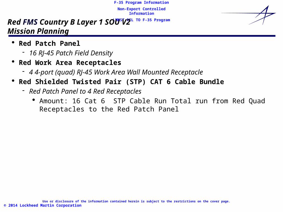
Red FMS Country B Layer 1 SOU V2Mission Planning
· Red Patch Panel- 16 RJ-45 Patch Field Density
· Red Work Area Receptacles- 4 4-port (quad) RJ-45 Work Area Wall Mounted Receptacle
· Red Shielded Twisted Pair (STP) CAT 6 Cable Bundle- Red Patch Panel to 4 Red Receptacles
· Amount: 16 Cat 6 STP Cable Run Total run from Red Quad Receptacles to the Red Patch Panel

Use or disclosure of the information contained herein is subject to the restrictions on the cover page.
F-35 Program Information
Non-Export Controlled Information
LMMST REL TO F-35 Program
© 2014 Lockheed Martin Corporation
Red FMS Country B Layer 1 SOU V2 andMission Planning Layer 1 ALIS GFE (w/INEs)
· Red Shielded Twisted Pair CAT 6 Patch Cords- CPE C to SOU Classified S/Collateral Server
· Amount:1 Total (Purple)· Lengths: xx – 10’
- CPE C to SOU Classified S/SAR Server· Amount:1 Total (Blue)· Lengths: xx – 10’
- OMS WS to Red Receptacle RJ -45 jacks· Amount: 8 Total (Orange)· Lengths: xx – 10’
- Red Patch Panel (OMS WS) to Mission Planning Support Module· Amount:4 Total (Orange)· Lengths: xx – 10’
- Red Patch Panel (OMS WS) to GDR (Mission Plan Download and Upload) (Orange)· Amount: 4 Total (Orange)· Lengths: xx – 10’
- OMS Collaboration WS to Red Receptacle RJ-45 jacks· Amount: 4 Total (Purple)· Lengths: xx – 10’
- Red Patch Panel (OMS Collaboration WS ) to Mission Planning Support Module (OMS Collaboration Switch)(Red)· Amount: 4 Total (Purple)· Lengths: xx – 10’”
Use or disclosure of the information contained herein is subject to the restrictions on the cover page.
F-35 Program Information
Non-Export Controlled Information
LMMST REL TO F-35 Program
© 2014 Lockheed Martin Corporation
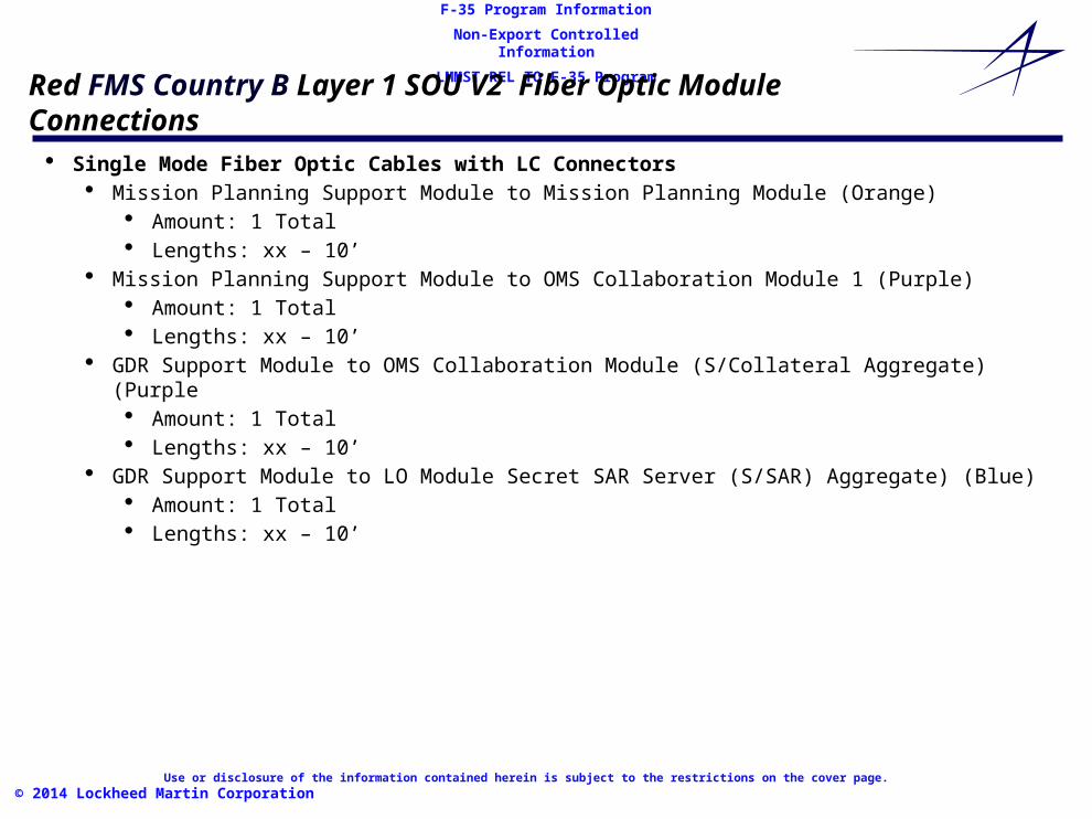
Red FMS Country B Layer 1 SOU V2 Fiber Optic Module Connections· Single Mode Fiber Optic Cables with LC Connectors
· Mission Planning Support Module to Mission Planning Module (Orange)· Amount: 1 Total· Lengths: xx – 10’
· Mission Planning Support Module to OMS Collaboration Module 1 (Purple)· Amount: 1 Total· Lengths: xx – 10’
· GDR Support Module to OMS Collaboration Module (S/Collateral Aggregate) (Purple· Amount: 1 Total· Lengths: xx – 10’
· GDR Support Module to LO Module Secret SAR Server (S/SAR) Aggregate) (Blue)· Amount: 1 Total· Lengths: xx – 10’

Use or disclosure of the information contained herein is subject to the restrictions on the cover page.
F-35 Program Information
Non-Export Controlled Information
LMMST REL TO F-35 Program
© 2014 Lockheed Martin Corporation
FMS Requirements Standards and Specifications
Standards and Specification References:First Four Hundred Feet,38 EIG Handbook
ETL O2-12 Communications and Information System Criteria for Air Force Facilities Criteria for Air Force Facilities
38 EIG Handbook 33-01 Communications and Information FIRST FOUR HUNDRED FEET
National Security Telecommunications and Information System Security Manual 2-95 Red/Black Seperation Guidance
Director of Intelligence Directive (DCID) 6/9 Physical Security Standards for Sensitive Compartmented Information Facilities
F35JSF Facilities Requirements Document 2014
Unified Facilities Criteria-3-580-01 Telecommunications Building Cabling Systems Planning and Design
UFC-3-701-01 DoD Facilities Pricing Guide for FY 2010
DoD Directive 8500.01E Department of Defense Information Assurance
AFSSI 7702 Emmisions Security Counter Measure Reviews
AFSSI 7703 Communications Security: Protected Distribution System
Related Documents