Use of Simulation in Railway Use of Simulation in Railway Vehicle Acceptance Vehicle Acceptance Procedures Procedures Javier Pérez & Paul Allen Bjorn Van Uem November 2004 November 2004

Welcome message from author
This document is posted to help you gain knowledge. Please leave a comment to let me know what you think about it! Share it to your friends and learn new things together.
Transcript
Use of Simulation in Railway Use of Simulation in Railway Vehicle Acceptance Vehicle Acceptance
ProceduresProcedures
Javier Pérez & Paul Allen Bjorn Van Uem
November 2004November 2004
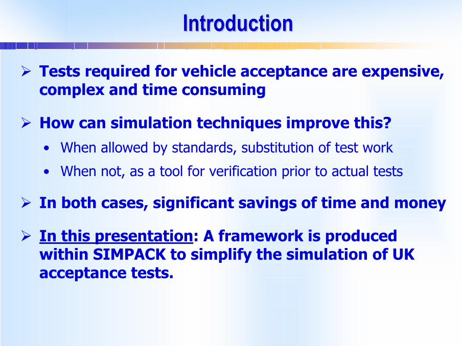
IntroductionIntroduction
Tests required for vehicle acceptance are expensive, complex and time consuming
How can simulation techniques improve this?• When allowed by standards, substitution of test work
• When not, as a tool for verification prior to actual tests
In both cases, significant savings of time and money
In this presentation: A framework is produced within SIMPACK to simplify the simulation of UK acceptance tests.
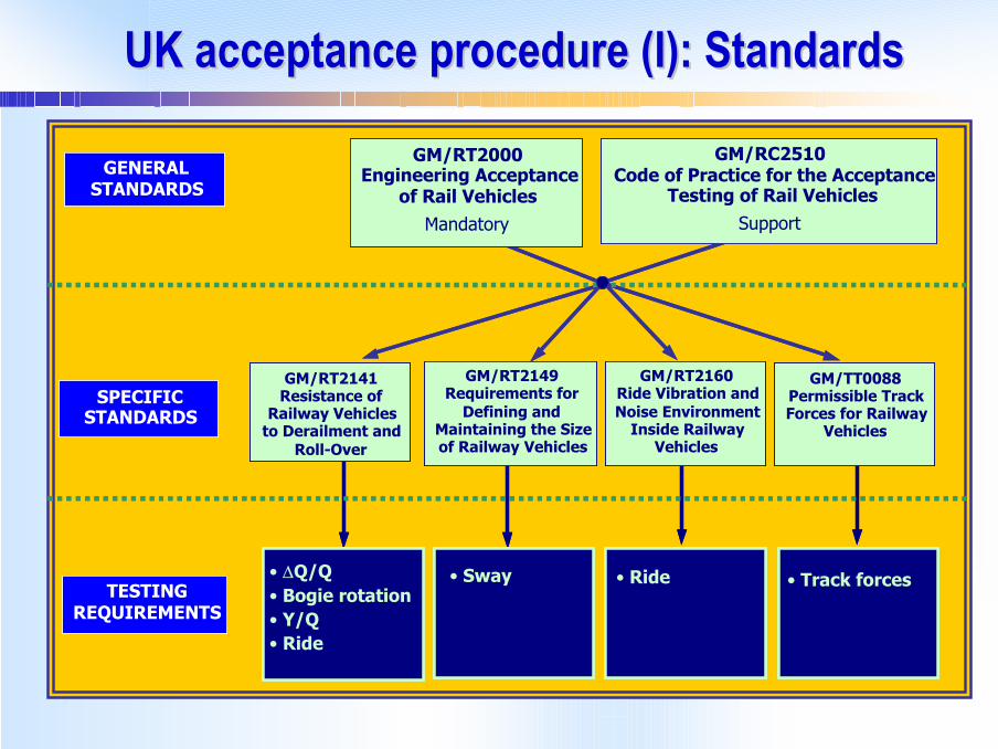
UK acceptance procedure (I): StandardsUK acceptance procedure (I): Standards
?Gauging - time domain
?Ride – time domain
?Track forces –Time domainREQUIREMENTS
• ∆Q/Q• Bogie rotation• Y/Q• Ride
• Track forces TESTINGREQUIREMENTS
• Ride• Sway
GM/RT2141Resistance of
Railway Vehicles to Derailment and
Roll-Over
GM/RT2149Requirements for
Defining and Maintaining the Size of Railway Vehicles
GM/RT2160Ride Vibration and Noise Environment
Inside Railway Vehicles
SPECIFIC STANDARDS
GM/TT0088Permissible Track Forces for Railway
Vehicles
GM/RT2141Resistance of
Railway Vehicles to Derailment and
Roll-Over
GM/RT2149Requirements for
Defining and Maintaining the Size of Railway Vehicles
GM/RT2160Ride Vibration and Noise Environment
Inside Railway Vehicles
SPECIFIC STANDARDS
GM/TT0088Permissible Track Forces for Railway
Vehicles
GENERAL STANDARDS
GM/RT2000Engineering Acceptance
of Rail VehiclesMandatory
GM/RC2510Code of Practice for the Acceptance
Testing of Rail VehiclesSupport
GENERAL STANDARDS
GM/RT2000Engineering Acceptance
of Rail VehiclesMandatory
GM/RC2510Code of Practice for the Acceptance
Testing of Rail VehiclesSupport
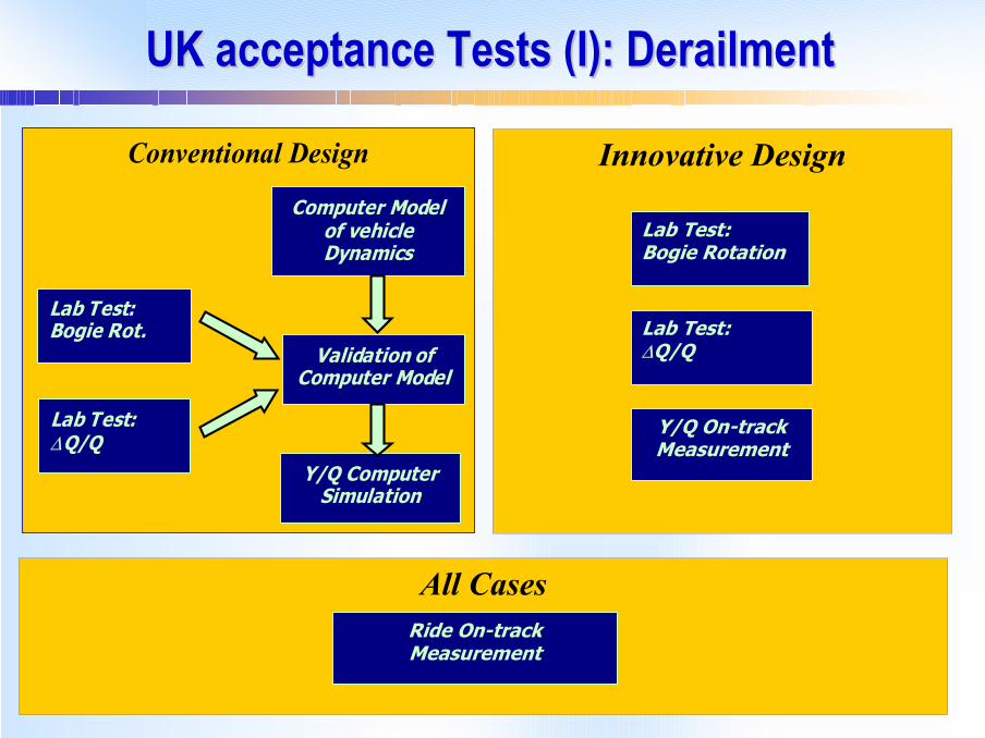
UK acceptance Tests (I): DerailmentUK acceptance Tests (I): Derailment
Conventional Design
Lab Test:Bogie Rot.
Lab Test:∆Q/Q
Computer Model of vehicle Dynamics
Validation of Computer Model
Y/Q Computer Simulation
Conventional Design
Lab Test:Bogie Rot.
Lab Test:∆Q/Q
Lab Test:Bogie Rot.
Lab Test:∆Q/Q
Computer Model of vehicle Dynamics
Validation of Computer Model
Y/Q Computer Simulation
All CasesRide On-track Measurement
Innovative Design
Y/Q On-track Measurement
Lab Test:Bogie Rotation
Lab Test:∆Q/Q
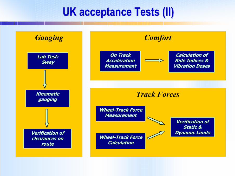
UK acceptance Tests (II)UK acceptance Tests (II)
Gauging
Lab Test:Sway
Kinematicgauging
Verification of clearances on
route
Comfort
On Track Acceleration
Measurement
Calculation of Ride Indices &
Vibration Doses
Track Forces
Wheel-Track ForceMeasurement
Verification of Static &
Dynamic LimitsWheel-Track Force
Calculation
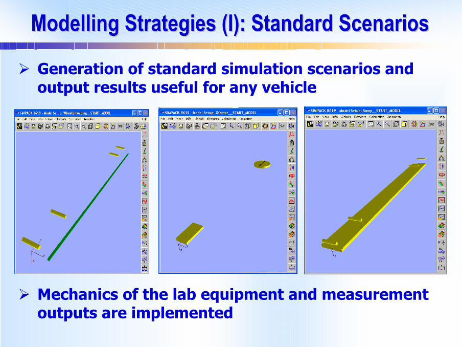
Modelling Strategies (I): Standard ScenariosModelling Strategies (I): Standard Scenarios
Generation of standard simulation scenarios and output results useful for any vehicle
Mechanics of the lab equipment and measurement outputs are implemented
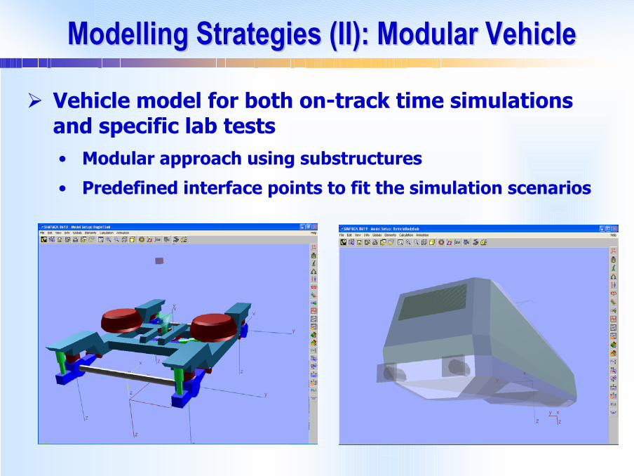
Modelling Strategies (II): Modular VehicleModelling Strategies (II): Modular Vehicle
Vehicle model for both on-track time simulations and specific lab tests • Modular approach using substructures
• Predefined interface points to fit the simulation scenarios

Modelling Strategies (III): Complete Process Modelling Strategies (III): Complete Process Common Database
Vehicle
Test Scenarios Test Simulation
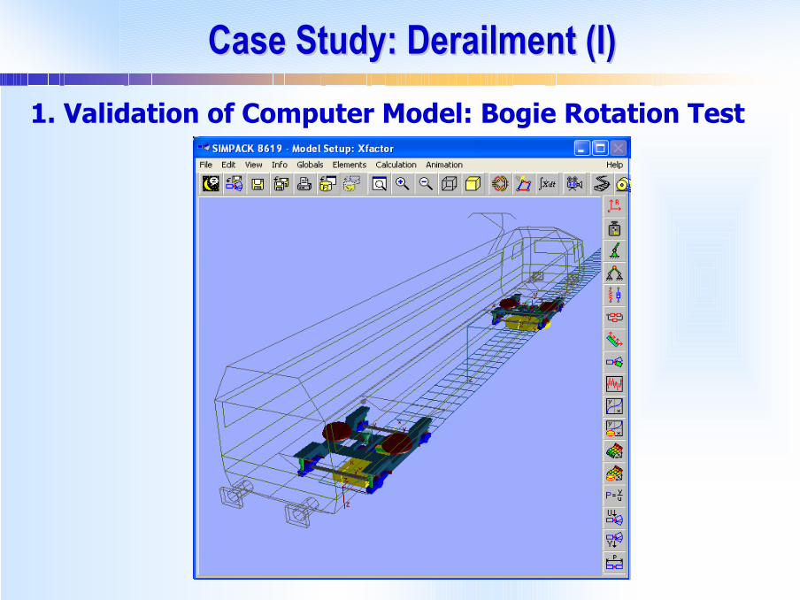
Case Study: Derailment (I)Case Study: Derailment (I)1. Validation of Computer Model: Bogie Rotation Test
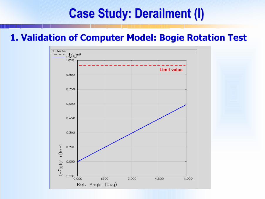
Case Study: Derailment (I)Case Study: Derailment (I)1. Validation of Computer Model: Bogie Rotation Test
Limit value
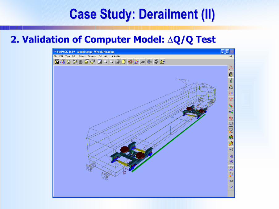
Case Study: Derailment (II)Case Study: Derailment (II)2. Validation of Computer Model: ∆Q/Q Test
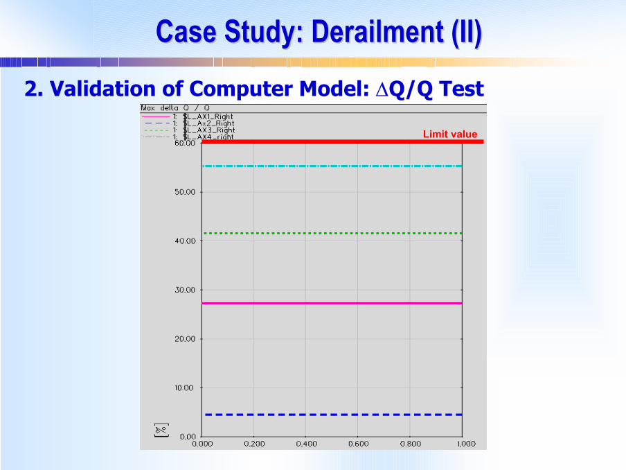
Case Study: Derailment (II)Case Study: Derailment (II)2. Validation of Computer Model: ∆Q/Q Test
Limit value
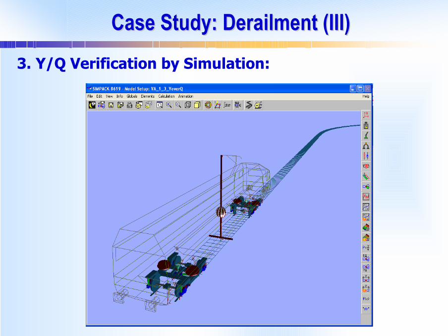
Case Study: Derailment (III)Case Study: Derailment (III)3. Y/Q Verification by Simulation:
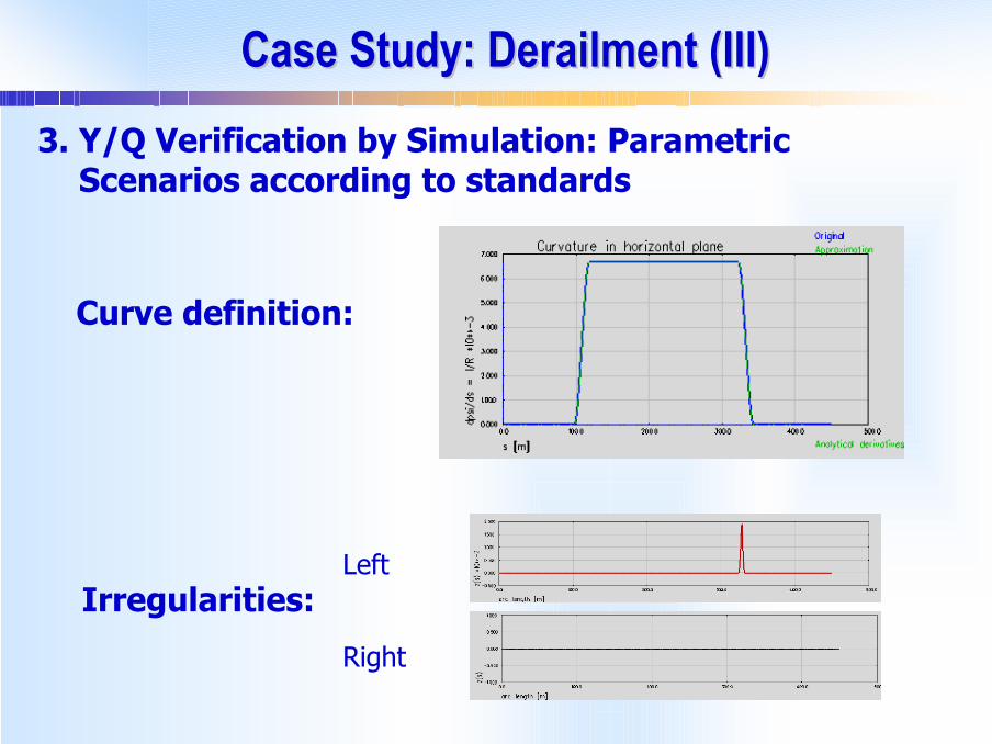
Case Study: Derailment (III)Case Study: Derailment (III)3. Y/Q Verification by Simulation: Parametric
Scenarios according to standards
Curve definition:
Irregularities:Left
Right
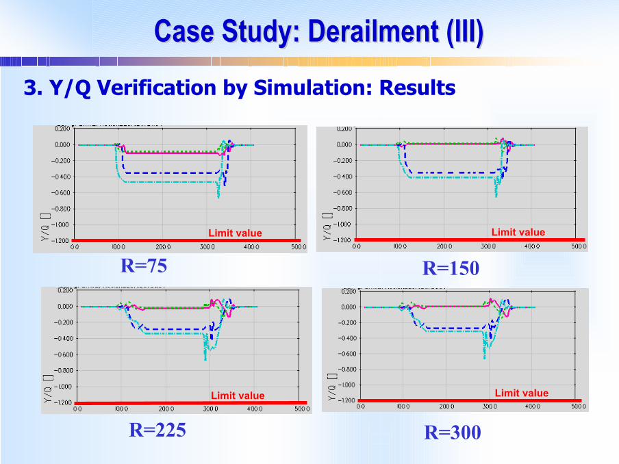
Case Study: Derailment (III)Case Study: Derailment (III)3. Y/Q Verification by Simulation: Results
R=300
R=150R=75
R=225
Limit value Limit value
Limit valueLimit value
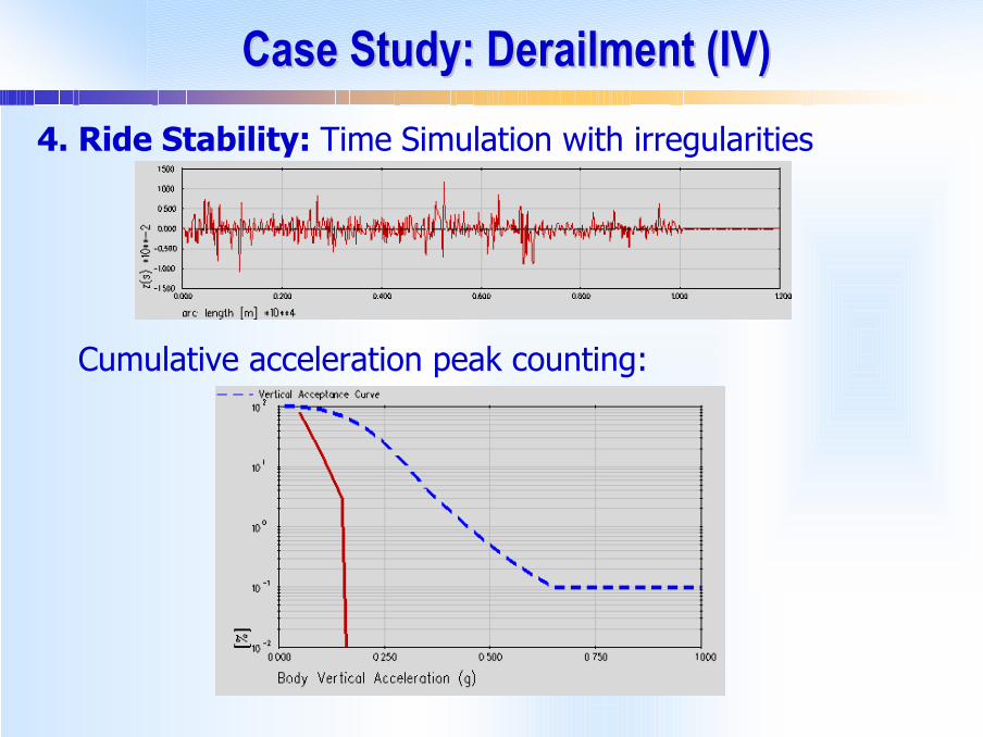
Case Study: Derailment (IV)Case Study: Derailment (IV)4. Ride Stability: Time Simulation with irregularities
Cumulative acceleration peak counting:

Case Study: GaugingCase Study: Gauging
Sway Test: Simulation of laboratory test
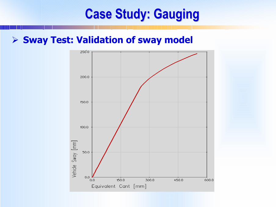
Case Study: GaugingCase Study: Gauging
Sway Test: Validation of sway model

Case Study: Ride Comfort & Track ForcesCase Study: Ride Comfort & Track ForcesRide and track forces from time simulation

Case Study: Ride Comfort & Track Forces (II)Case Study: Ride Comfort & Track Forces (II)Time Simulation. Flexible vehicle body model necessary for comfort assessment.

Case Study: Ride Comfort & Track Forces (II)Case Study: Ride Comfort & Track Forces (II)
Comfort indices

Case Study: Ride Comfort & Track Forces (II)Case Study: Ride Comfort & Track Forces (II)Results: Lateral Track Force
Limit Value
Limit Value
Limit Value
Limit Value
Limit Value
Limit Value
Limit Value
Limit Value
ConclusionsConclusions
Creation of a new framework where the computer simulation of acceptance tests becomes a routine task
SIMPACK offers the features to achieve this: Flexibility, modularity, parametric modelling based on a database
These tools can be used to save time and money in the vehicle acceptance process
Future acceptance requirements expected to move towards more computer based simulation than actual tests
Related Documents