Use of Electro- Pneumatics in Automation systems By : J.G.Varuna Priyanka

Use of Electro-Pneumatics in Automation Systems
Dec 15, 2015
Electro-Pneumatics in Automation
Welcome message from author
This document is posted to help you gain knowledge. Please leave a comment to let me know what you think about it! Share it to your friends and learn new things together.
Transcript

Use of Electro-Pneumatics in Automation systems
By : J.G.Varuna Priyanka

Basis of Pneumatics
• Uses compressed Air• Compressed Air is manipulated to do Mechanical
work – To produce motion and force• Pneumatic drives converts the energy stored in
the compressed Air into motion or force.

Basis of Pneumatics
• Cylinders – Are the most common type of drives
• Robust construction• A large range of types based on stroke,
pressure…etc• Simple installation and• May be at a comfortable price

Basis of Pneumatics
• Some common applications of pneumatics are,– Handling of work pieces• Clamping• Positioning• Separating• Stacking• Rotating
– Packaging– Filling– Opening and closing doors – in buses and trains– Metal forming – such as embossing andpressing– stamping

Basis of Pneumatics• A processing station

Control aspects of Pneumatics
• Pneumatic drives can only do work usefully if their motions are precise and carried out at the right time and in the right sequence.
• Coordinating the sequence of motion is the task of the controller.
• Control aspects come in– Design and– Structuring controls

Basis of Pneumatics
• Control aspects– Usually goes for Open Loop controls– process taking place in a system– whereby one or more variables in the form of
input variables exert influence on other variables in the form of output variables by reason of the laws which characterize the system
– Process characterized by open sequence of action via the individual transfer elements or the control chain

Basis of Pneumatics
• The term open loop control is widely used not only for the process of controlling but also for the plant as a whole.– An example : A device closes metal cans with a lid. – The closing process is triggered by operation of a
pushbutton at the workplace. When the pushbutton is released, the piston retracts to the retracted end position.
– Position of the pushbutton is input variable– Position of the pressing cylinder is the output variable– The loop is open because the output variable has no
influence on the input variable

Basis of Pneumatics

Basis of Pneumatics
• Controls must evaluate and process information – For example - pushbutton pressed or not pressed
• The information is represented by signals. A signal is a physical variable, for example– The pressure at a particular point in a pneumatic
system– The voltage at a particular point in an electrical �
circuit

Basis of Pneumatics

Basis of Pneumatics
Basis of Pneumatics
• A signal is the representation of information• An analog signal is a signal in which information
is assigned point by point to a continuous value range of the signal parameter
• In the case of a pressure gauge, each pressure value is assigned a particular display value
• If the signal rises or falls, the information changes continuously.

Basis of Pneumatics
• A digital signal is a signal with a finite number of value ranges of the information parameter.
• Each value range is assigned a specific item of information
• The graph shows a typical ADC (Analog to Digital Convertion)
• A binary signal is a digital signal with only two value ranges for the information parameter. These are normally designated o and 1

Basis of Pneumatics
• Classification of controls
Basis of Pneumatics
• Logic controller– A logic controller generates output signals through
logical association of input signals.– The assembly device can be operated from two
positions. The two output signals are linked. The piston rod advances if either pushbutton 1 or 2 is pressed or if both are pressed.

Basis of Pneumatics
• Sequence controller– A sequence controller is characterized by its step by step
operation. The next step can only be carried out when certain criteria are met.
– Drilling station– The first step is clamping of the work piece. As soon as– the piston rod of the clamping cylinder has reached the
forward end position, this step has been completed. – The second step is to advance the drill. – When this motion has been completed the third step is
carried out.

Basis of Pneumatics
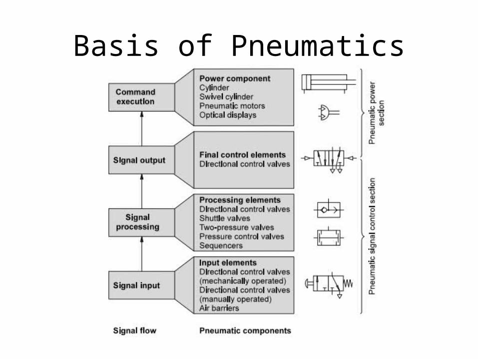
• A controller can be divided into the functions– Signal input– Signal processing– Signal output and – Command execution
• Signals from the signal input are logically associated (signal processing). Signals for signal input and signal process are low power signals. Both functions are part of the signal control section.

Basis of Pneumatics
• At the signal output stage, signals are amplified from low power to high power.
• Signal output forms the link between the signal control section and the power section.
• Command execution takes place at a high power level – that is, in
• order to reach a high speed (such as for fast ejection of a work piece from a machine) or to exert a high force (such as for a press).
• Command execution belongs to the power section of a control system.

Basis of Pneumatics

Basis of Pneumatics
• Pneumatic and electro-pneumatic control systems
• In a pneumatic control the typical control components are– Various types of valves– Sequencers– Air barriers, etc.
Basis of Pneumatics
• In an electro-pneumatic control the signal control section is made up of a electrical components– Electrical input buttons– Proximity switches– Solenoid valves– Relays or – Programmable Logic Controller.
Basis of Pneumatics

Basis of Pneumatics
Basis of Pneumatics
• Electro-Pneumatic control systems are depicted in two separate circuits– For Electrical– For Pneumatics

Basis of Pneumatics

Basis of Pneumatics
• Advantages of electropneumatic controllers– Electropneumatic controllers have the following
advantages over pneumatic control systems• Higher reliability (fewer moving parts subject to wear)• Lower planning and commissioning effort, particularly �
for complex controls• Lower installation effort, particularly when modern �
components such as valve terminals are used• Simpler exchange of information between several
controllers

Fundamentals of electrical technology
• Direct current and alternating current

Fundamentals of electrical technology
Fundamentals of electrical technology
• The solenoid coil of a pneumatic 5/2-way valve is supplied with 24 VDC. The resistance of the coil is 60 Ohm. What is the power?

Fundamentals of electrical technology
• Functionality of a solenoid– A magnetic field is induced when a current is
passed through an electrical conductor. The strength of the magnetic field is proportional to the current.
– Magnetic fields attract iron, nickel and cobalt. – The attraction increases with the strength of the
magnetic field.

Fundamentals of electrical technology
Components of Pneumatic systems
• Power supply unit– The signal control section of an electropneumatic
controller is supplied with power via the electrical mains. The individual assemblies of the power supply unit have the following tasks• The transformer reduces the operating voltage – 230V
to 24V• The rectifier converts the AC voltage into DC voltage• Maintain a constant voltage regardless of supply
voltage fluctuations

Components of Pneumatic systems

Components of Pneumatic systems
• Push button and control switches– Switches are installed in circuits to apply a current to a
load or to interrupt the circuit. – These switches are divided into pushbuttons and control
switches.• Control switches are mechanically detented in the selected
position. The switch position remains unchanged until a new switch position is selected.
• Example: Light switches in the home.• Push button switches only maintain the selected position as
long as the switch is actuated (pressed). • Example: Bell push.

Components of Pneumatic systems
• Normally open contact

Components of Pneumatic systems
• Normally closed contact

Components of Pneumatic systems
• Changeover contact

Components of Pneumatic systems
• Sensors are primarily used for the following purposes– To detect the advanced and retracted end position
of the piston rod in cylinder drives – To detect the presence and position of workpieces – To measure and monitor pressure
Components of Pneumatic systems
• A limit switch– A limit switch is actuated when a machine part or
workpiece is in a certain position. Normally, actuation is effected by a cam.
– Limit switches are normally changeover contacts. – They can then be connected – as required – as a
normally open contact, normally closed contact or changeover contact.

Components of Pneumatic systems
• A limit switch

Components of Pneumatic systems
• Proximity switches– In contrast to limit switches, proximity switches
operated contactless (non-contact switching) and without an external mechanical actuating force.
– The following types of proximity switch are differentiated: • Reed switch • Inductive proximity switch• Capacitive proximity switch• Optical proximity switch

Components of Pneumatic systems
• A Read Switch

Components of Pneumatic systems
• Inductive proximity sensor

Components of Pneumatic systems
• Capacitive proximity sensor

Components of Pneumatic systems
• Optical proximity sensor
Components of Pneumatic systems
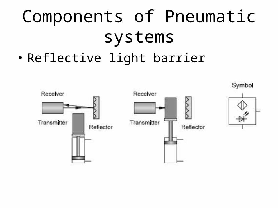
• Reflective light barrier

Components of Pneumatic systems
• Diffuse reflective optical sensor

Components of Pneumatic systems

Components of Pneumatic systems• Analogue pressure sensors

Components of Pneumatic systems

Components of Pneumatic systems
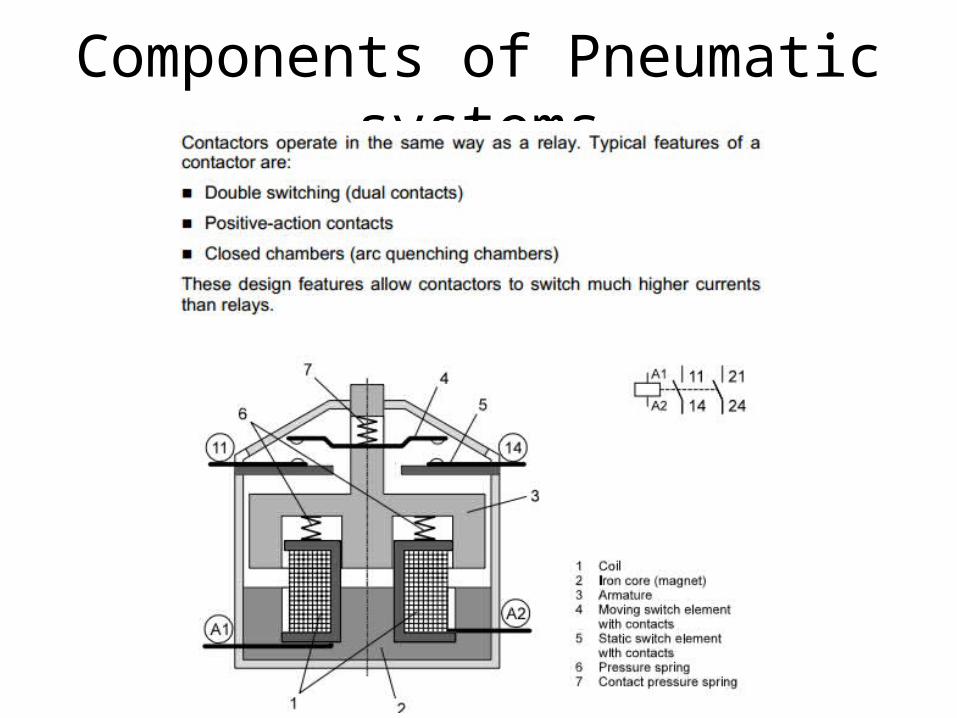
• Applications of relays– In electropneumatic control systems, relays are
used for the following functions• Signal multiplication• Delaying and conversion of signals• Association of information• Isolation of control circuit from main circuit• In purely electrical controllers, the relay is also used for
isolation of DC and AC circuits.

Components of Pneumatic systems
• Retentive relay– The retentive relay responds to current pulses:• The armature is energized when a positive pulse is
applied.• The armature is de-energized when a negative pulse is
applied.• If no input signal is applied, the previously set switch
position is retained (retention).• The behavior of a retentive relay is analogous to that of
a pneumatic double pilot valve, which responds to pressure pulses.
Components of Pneumatic systems

Components of Pneumatic systems
• Programmable logic controllers

2/2 Way Directional Control Valve
The circuit symbol describes the operation of the valve.

Device Activated
Air In
Air Out
Symbol Operation
Air In
Air Blocked
To see how the symbol works, consider the animation below.
Air is now allowed through the valve to the output.
Air is initially blocked from passing through the valve.

3/2 Directional Control Valve Normally Closed
A 3/2 valve allows exhaust air to vent to atmosphere in the ‘off’ position.

3/2 Directional Control Valve Normally Open

5/2 Directional Control Valve 3/2 Wegeventil
A five port valve switches the two output ports from exhaust/pressure to pressure/exhaust.
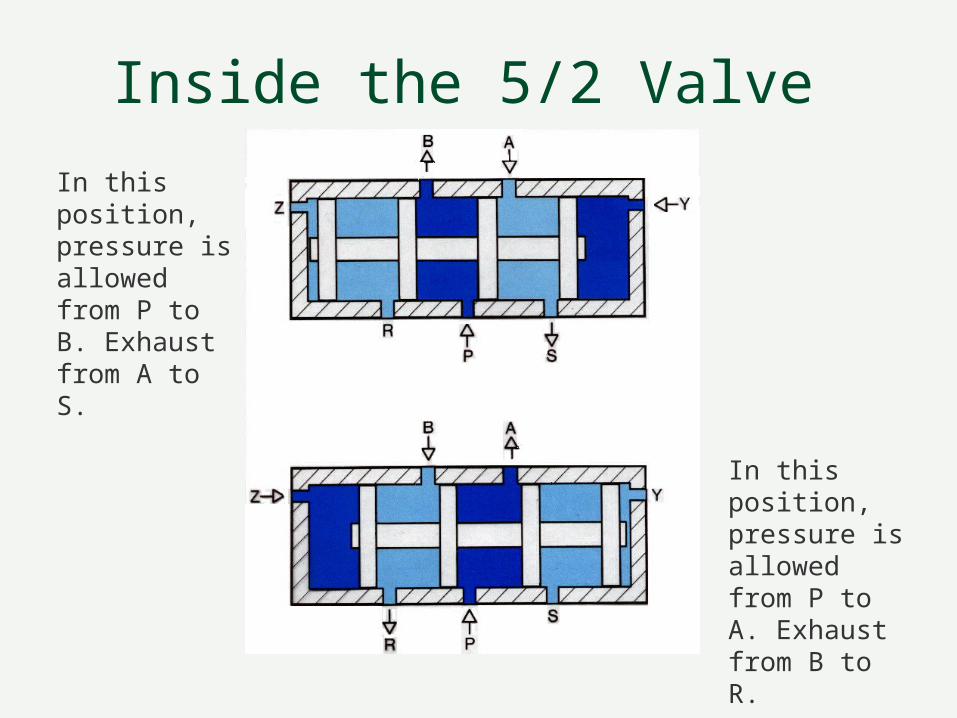
Inside the 5/2 Valve
In this position, pressure is allowed from P to B. Exhaust from A to S.
In this position, pressure is allowed from P to A. Exhaust from B to R.

Spool OperationThis animation shows the spool (schieber) operating when each pilot is operated.

Cylinder
Also known as a linear actuator. This is the component that provides the movement to achieve the machine operation.

Cushion Operation

5/2 Valve Operation
Device Activated
The animation shows the operation of a 5/2 DCV when connected to a differential cylinder.
In this position, pressure is connected to the front of the cylinder.
When the device is activated, pressure is switched to the back of the cylinder which now extends. Note that in both positions, air must be able to escape via the exhaust ports.

Two Pressure Valve (AND)
Input 1 Input 2
Output
An output is achieved when input 1 AND input 2 are activated.

Shuttle Valve (OR)
Input 1 Input 2
Output
An output is achieved when input 1 OR input 2 are activated.

Pressure Regulator With Relief Port
The output pressure is regulated by the spring pressure.

Inside the Regulator
Output pressure acts on the diaphragm against the spring.
Input pressure is allowed through the normally open valve.
When the output pressure is greater than the spring force the valve closes.

The Regulator in Action

FilterThe filter is used to remove small particles from the air. If the particles are left in the air they will cause the pneumatic components to stick.

Inside the FilterAir must pass through the filter in order to get to the outlet.
Water in the air is allowed to fall into the water bowl. The bowl must be drained regularly.
Output air is cleaner and drier.

LubricatorThe lubricator puts a mist of oil into the air. This lubricates the internal components of the pneumatic valves.

Inside the Lubricator
Air flows through the orifice causing a drop in pressure.
Oil is drawn from the bowl due to the pressure drop

RestrictionsRestrictions are used to control the air flow to pneumatic devices. The speed of the pneumatic devices will therefore be controlled.

Non Return ValvesRuckschlagventil
Check valves are used to allow air in one direction only.
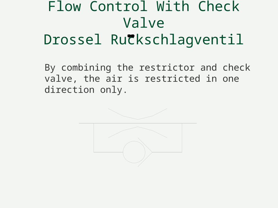
Flow Control With Check ValveDrossel Ruckschlagventil
By combining the restrictor and check valve, the air is restricted in one direction only.

Inside the Restrictor and Check Valve
Air in this direction closes the check valve and is forced through the restriction.
Air in this direction opens the check valve. The restriction is now bypassed.

Valve Actuators
Push Button Hand Lever
Pilot Solenoid (Elektromagnete)
Pilot Or Solenoid Pilot And Solenoid
Many valves are actuated by some mechanical or electrical method. Below are some common actuation symbols.

Pilot/Spring operation on a 5/2 Valve
Before the button is pressed, the spring holds the valve spool in the spring position.
When the button is pressed, the button force overcomes the spring force and the valve switches position.

Simple Circuit Operation

The Complete System
Components of Pneumatic systems
Components of Pneumatic systems
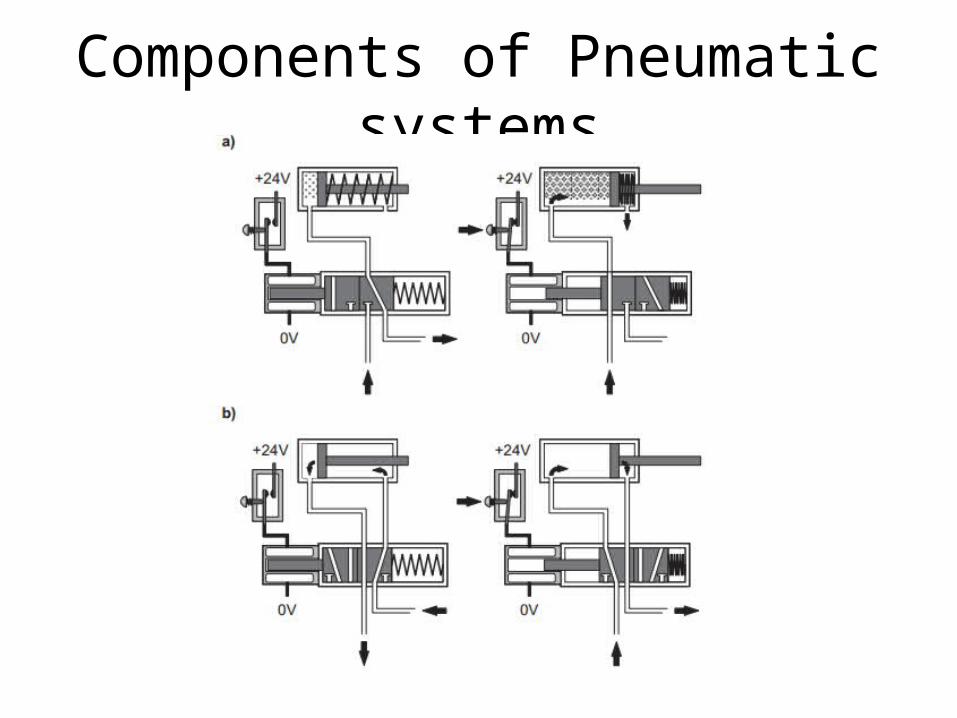
• Action – Figure a) shows when there is “no power” the
spring is on “normal” position and “cylinder retracts”.
– When the “power is on” the solenoid valve changes position to flow air and “cylinder extends”

Components of Pneumatic systems
• Action – Figure b) shows the action of “double acting
cylinder” with a 5/2 way solenoid valve.– At the “no power” left cylinder chamber vents– The right cylinder chamber gets pressurized– At “power on” position the cylinder acts opposite.

Components of Pneumatic systems
Related Documents