[Singh*, 4.(6): June, 2015] ISSN: 2277-9655 (I2OR), Publication Impact Factor: 3.785 http: // www.ijesrt.com © International Journal of Engineering Sciences & Research Technology [733] IJESRT INTERNATIONAL JOURNAL OF ENGINEERING SCIENCES & RESEARCH TECHNOLOGY USE OF DSTATCOM IN REACTIVE CONTROL Satnam Singh*, Neeraj Sharma * Student, M.Tech EE Department, BBSBEC, Fatehgarh Sahib, Punjab,India Asst Prof, EE Department, BBSBEC, Fatehgarh Sahib, Punjab,India ABSTRACT In this paper work among the different custom power devices, the role of DSTATCOM has been investigated to improve the quality of power under different conditions.. For this Self-Excited Induction Generators (SEIGs) are used which also presented the significance of renewable source of energy (solar energy, wind energy, geothermal energy, tidal energy) in energy crisis. The two SEIG’s are connected in para llel, to get better power supply to the consumers. When the SEIG attains steady state condition, double loading will cause decrease in magnitude of generated voltage and shoot-up the current. In this paper effect of various power quality problems is analyzed i.e. by inserting three phase fault, by unbalancing the test system and by double loading the system. Under these conditions DSTATCOM will work as a regulator .The proposed controller used to control both current and voltage in the generator terminal. The proposed controllers consist of static synchronous compensator (DSTATCOM) which recompenses the loads and to make available the required reactive power of induction generators under loaded condition. The STATCOM consist of insulated gate bipolar transistor (IGBT) and any shortage of power in a grid is leveled by a BESS (Battery Energy Storage System) used with the DSTATCOM. The proposed generating system is simulated in MATLAB platform along with Simulink. KEYWORDS: SEIG (Self-Excited Induction Generators) MATLAB, IGBT, DSTATCOM. INTRODUCTION Now a days due to exhaustion of fossil fuel and also the increasing cost has forced mankind to look for (1) proficient and proper use of conventional fuel (2) or use of nonconventional source of energy. Consequently improving power quality and use of nonconventional resources has become the main area to be focused in modern electric power system. Solar wind and hydro are some of the sources of energy which can be renewed in nature and have not been fully exploited. Focus has now shifted to these unexploited sources of energy. Small hydro generation plants exist in relatively large number in the remote locations of the hills. These have the ability to feed local loads and with superior quality of power at relatively less cost. Also to provide the power to these inaccessible areas using overhead conductors or cables is not feasible due to too expensive cost of transmission system. One generator which met all of the requirements is the induction generator. Therefore Self-Excited Induction Generators with its excitation condition being met by a capacitor bank connected across its terminals, has become the most appropriate option. In spite of the advantages, SEIG suffers from its intrinsic poor voltage regulation. D-STATCOM can be successfully utilized to control voltage for a series of small Induction motors loads which draw huge starting currents (5-6 times) of full rated current and may have an effect on working of sensitive loads. In early times Thyristor based systems were used for reactive power Compensation and for voltage flicker reduction due to arc furnace loads, but due to deficiency of passive devices such as large size, fixed compensation possibility of resonance etc, the use of innovative compensators such as D-STATCOM is growing to solve the power quality problems. The reason of D-STATOM is to supply efficient voltage regulation during short duration of SEIG starting; loading and unloading and faulty situations and thus prevent large voltage swing. POWER SYSTEM CONFIGURATION Fig. 1 shows the schematic of the self-sufficient power system. In this three phase squirrel cage induction generator 4kW, 400V, 50Hz, 1440 rpm is used and feeds power to a distribution system having two loads at consumer end. A

Welcome message from author
This document is posted to help you gain knowledge. Please leave a comment to let me know what you think about it! Share it to your friends and learn new things together.
Transcript

[Singh*, 4.(6): June, 2015] ISSN: 2277-9655
(I2OR), Publication Impact Factor: 3.785
http: // www.ijesrt.com © International Journal of Engineering Sciences & Research Technology
[733]
IJESRT INTERNATIONAL JOURNAL OF ENGINEERING SCIENCES & RESEARCH
TECHNOLOGY
USE OF DSTATCOM IN REACTIVE CONTROL Satnam Singh*, Neeraj Sharma
* Student, M.Tech EE Department, BBSBEC, Fatehgarh Sahib, Punjab,India
Asst Prof, EE Department, BBSBEC, Fatehgarh Sahib, Punjab,India
ABSTRACT In this paper work among the different custom power devices, the role of DSTATCOM has been investigated to
improve the quality of power under different conditions.. For this Self-Excited Induction Generators (SEIGs) are used
which also presented the significance of renewable source of energy (solar energy, wind energy, geothermal energy,
tidal energy) in energy crisis. The two SEIG’s are connected in parallel, to get better power supply to the consumers.
When the SEIG attains steady state condition, double loading will cause decrease in magnitude of generated voltage
and shoot-up the current. In this paper effect of various power quality problems is analyzed i.e. by inserting three
phase fault, by unbalancing the test system and by double loading the system. Under these conditions DSTATCOM
will work as a regulator .The proposed controller used to control both current and voltage in the generator terminal.
The proposed controllers consist of static synchronous compensator (DSTATCOM) which recompenses the loads and
to make available the required reactive power of induction generators under loaded condition. The STATCOM consist
of insulated gate bipolar transistor (IGBT) and any shortage of power in a grid is leveled by a BESS (Battery Energy
Storage System) used with the DSTATCOM. The proposed generating system is simulated in MATLAB platform
along with Simulink.
KEYWORDS: SEIG (Self-Excited Induction Generators) MATLAB, IGBT, DSTATCOM.
INTRODUCTIONNow a days due to exhaustion of fossil fuel and also the increasing cost has forced mankind to look for (1) proficient
and proper use of conventional fuel (2) or use of nonconventional source of energy. Consequently improving power
quality and use of nonconventional resources has become the main area to be focused in modern electric power system.
Solar wind and hydro are some of the sources of energy which can be renewed in nature and have not been fully
exploited. Focus has now shifted to these unexploited sources of energy. Small hydro generation plants exist in
relatively large number in the remote locations of the hills. These have the ability to feed local loads and with superior
quality of power at relatively less cost. Also to provide the power to these inaccessible areas using overhead conductors
or cables is not feasible due to too expensive cost of transmission system. One generator which met all of the
requirements is the induction generator. Therefore Self-Excited Induction Generators with its excitation condition
being met by a capacitor bank connected across its terminals, has become the most appropriate option.
In spite of the advantages, SEIG suffers from its intrinsic poor voltage regulation. D-STATCOM can be successfully
utilized to control voltage for a series of small Induction motors loads which draw huge starting currents (5-6 times)
of full rated current and may have an effect on working of sensitive loads. In early times Thyristor based systems were
used for reactive power Compensation and for voltage flicker reduction due to arc furnace loads, but due to deficiency
of passive devices such as large size, fixed compensation possibility of resonance etc, the use of innovative
compensators such as D-STATCOM is growing to solve the power quality problems. The reason of D-STATOM is
to supply efficient voltage regulation during short duration of SEIG starting; loading and unloading and faulty
situations and thus prevent large voltage swing.
POWER SYSTEM CONFIGURATION Fig. 1 shows the schematic of the self-sufficient power system. In this three phase squirrel cage induction generator
4kW, 400V, 50Hz, 1440 rpm is used and feeds power to a distribution system having two loads at consumer end. A

[Singh*, 4.(6): June, 2015] ISSN: 2277-9655
(I2OR), Publication Impact Factor: 3.785
http: // www.ijesrt.com © International Journal of Engineering Sciences & Research Technology
[734]
micro hydro turbine provides constant power to the induction generator. The current and voltage of the asynchronous
generator and the load are used as feedback to the control system of the DSTATCOM.
Fig 1: Schematic diagram of the self-sufficient power system
DISTRIBUTION STATCOM Principle of Reactive Power Control
The principle of reactive power control via D-STATCOM is well known that the amount of type (capacitive or
inductive) of reactive power exchange between the D-STATCOM and the system can be adjusted by controlling the
magnitude of D-STATCOM output voltage with respect to that of system voltage. The reactive power supplied by the
D-STATCOM is given by-
Q= (Vi-VS)/X * Vs
Where, Q is the reactive power. Vi is the magnitude of D-STATCOM output voltage. VS is the magnitude of system
voltage. X is the equivalent impedance between D-STATCOM and the system. When Q is positive the D-STATCOM
supplies reactive power to the system. Otherwise, the D-STATCOM absorbs reactive power from the system
Load Compensation using D-STATCOM
The basic electronic block of the D-STATCOM is the voltage Source Converter (VSC) that converts an input DC
voltage into a three phase output voltage at fundamental frequency. In its most basic form, the D-STATCOM
configuration consists of a Voltage Source Converter (VSC), a DC capacitor for energy storage; a coupling transformer
connected in shunt with the AC system, and associated control circuits. In this arrangement, the steady state power
exchange between the device and the AC system is mainly reactive..
A SPWM control circuit, which gets feedback information about the generator and load voltages and currents, is used
to provide triggering pulses to the IGBTs of the VSC.
For the analysis we are using two types of loads, one is 300 km away which is connected through transmission line
and other is near the generating station. Three phase fault is inserted in the load which is at the distance of 300km and
its effect is analyzed and also three phase fault is inserted at PCC. On the other hand test system is also double loaded
by inserting the load for some point of time .By providing all these conditions the performance of DSTATCOM is
analyzed i.e how the DSTATCOM will provide reactive power when any poor condition will met and make the system
reliable.
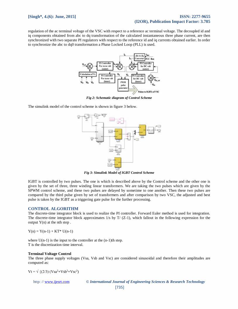
SINUSOIDAL PWM CONTROL SCHEME The control approach of the power system is presented in Fig.2. A high frequency carrier based sinusoidal PWM is
used for generating the switching pulses for the IGBTs of the VSC.
The three phase system is transformed to a synchronously rotating reference frame using Park’s transformation. The
compensation is achieved by control of id and iq. The immediate id reference current is generated by PI regulation of
the dc terminal voltage with respect to a reference dc voltage. In the same way iq reference current is generated by PI
[Singh*, 4.(6): June, 2015] ISSN: 2277-9655
(I2OR), Publication Impact Factor: 3.785
http: // www.ijesrt.com © International Journal of Engineering Sciences & Research Technology
[735]
regulation of the ac terminal voltage of the VSC with respect to a reference ac terminal voltage. The decoupled id and
iq components obtained from abc to dq transformation of the calculated instantaneous three phase current, are then
synchronized with two separate PI regulators with respect to the reference id and iq currents obtained earlier. In order
to synchronize the abc to dq0 transformation a Phase Locked Loop (PLL) is used.
Fig 2: Schematic diagram of Control Scheme
The simulink model of the control scheme is shown in figure 3 below.
Fig 3: Simulink Model of IGBT Control Scheme
IGBT is controlled by two pulses. The one is which is described above by the Control scheme and the other one is
given by the set of three, three winding linear transformers. We are taking the two pulses which are given by the
SPWM control scheme, and these two pulses are delayed by sometime to one another. Then these two pulses are
compared by the third pulse given by set of transformers and after comparison by two VSC, the adjusted and best
pulse is taken by the IGBT as a triggering gate pulse for the further processing.
CONTROL ALGORITHM The discrete-time integrator block is used to realize the PI controller. Forward Euler method is used for integration.
The discrete-time integrator block approximates 1/s by T/ (Z-1), which fallout in the following expression for the
output Y(n) at the nth step .
Y(n) = Y(n-1) + KT* U(n-1)
where U(n-1) is the input to the controller at the (n-1)th step.
T is the discretization time interval.
Terminal Voltage Control
The three phase supply voltages (Vsa, Vsb and Vsc) are considered sinusoidal and therefore their amplitudes are
computed as:
Vt = √ {(2/3) (Vsa2+Vsb2+Vsc2)

[Singh*, 4.(6): June, 2015] ISSN: 2277-9655
(I2OR), Publication Impact Factor: 3.785
http: // www.ijesrt.com © International Journal of Engineering Sciences & Research Technology
[736]
The value of Vt calculated above is compared with the desired amplitude of the terminal voltage Vtref. The ac voltage
amplitude error Ver(n) at the nth sampling instant is given by,
Ver(n) = (Vtref - Vt(n))
where Vt(n) is the amplitude of the sensed three phase ac voltage at the PCC terminal at the nth instant. The error
Ver(n) is fed to an outer PI controller, using discrete time integration, to generate the Iqref as
Iqref (n) = Iqref (n-1) + Kap {Ver(n) - Ver(n-1) } + Kai Ver(n)
where Kap and Kai are the proportional and integral gain Constants of the outer PI controller of the ac terminal voltage
at the PCC.
The calculated value of Iq is generated by an abc to dq convertor using Park’s transformation over the supply current.
The Iqref and Iq components are compared and the error is fed to an inner PI current controller to generate Vq .
Iqer(n) = (Iqref (n) - Iq(n))
Vq(n) = Vq(n-1) + Kbp {Iqer(n) - Iqer(n-1)} + Kbi Iqer(n)
where Kbp and Kbi are the proportional and integral gain constants of the inner PI controller of the ac terminal voltage
at the PCC.
Control of Voltage at the dc terminal of DSTATCOM
The Vdc of the dc bus is compared with the desired dc bus voltage Vdc_ref. The dc voltage error Vder(n) at the nth
sampling instant is given by
Vdcer(n) = (Vdc_ref - Vdc(n))
where Vdc(n) is the sensed dc voltage at the dc bus of the DSTATCOM at the nth instant.
The error is then fed to the outer PI controller to generate Idref as:
Idref (n) = Idref (n-1) + Kap{Vdcer(n) - Vdcer(n-1)} + KaiVdcer(n)
where Kap and Kai are the proportional and integral gain constants of the outer PI controller of the dc bus voltage.
The actual Id is generated by an ‘abc to dq’ convertor using Park’s transformation over the supply currents. The signals
Idref and Id are compared and the error is fed to an inner PI current controller to generate Vd.
Ider(n) = (Idref (n) - Id(n))
Vd(n) = Vd(n-1) + Kbp {Ider(n) - Ider(n-1)} + Kbi Ider(n)
where Kbp and Kbi are the proportional and integral gain constants of the inner PI controller of the dc bus voltage.
MATLAB MODELLING Figure 4 shows the MATLAB based simulation model of the power system along with its controller. A 4kW, 415V,
50Hz, 4-pole, Y-connected asynchronous machine is used for autonomous operation. The simulation is performed on
MATLAB platform in discrete mode.
SIMULATION MODELS

[Singh*, 4.(6): June, 2015] ISSN: 2277-9655
(I2OR), Publication Impact Factor: 3.785
http: // www.ijesrt.com © International Journal of Engineering Sciences & Research Technology
[737]
Fig 4: SIMULINK MODEL of Proposed System with DSTATCOM
Fig 5: Data Acquisition Block

[Singh*, 4.(6): June, 2015] ISSN: 2277-9655
(I2OR), Publication Impact Factor: 3.785
http: // www.ijesrt.com © International Journal of Engineering Sciences & Research Technology
[738]
Fig 6: SIMULINK MODEL of DSTATCOM
SIMULATION & RESULTS The below table shows the all parameters used here for the result analysis under changeable and three phase fault
conditions
Description Graph Parameter
SEIG Generator-1 voltage Vabc1
SEIG generator-1 current Iabc1
SEIG Generator-2 voltage Vabc2
SEIG Generator-2 current Iabc2
DSTATCOM currents Icabc
Load1(8KW) current at bus B4 Iabc4
load 2(4KW) current at bus B7 Iabc7
calculated terminal voltage at PCC Vt
measured value of dc side voltage Vdc
Speed of SEIG 1 & 2 N1, N2
Table 1
The response of SEIG’s under distribution loads and other three phase fault conditions at different time periods is
shown in graphs below.
The BESS based DSTATCOM supplies the extra power causing a true operation of the system when the load on the
SEIG Generators increases ahead of its rated capacity.
Time Period Description
0.0 s Load 1 (8KW) start + Load 2 (4KW)
start
0.2s to 0.3s Additional Load 3 (8KW) inserted
0.4s Three phase fault short circuit to
ground inserted at B7
0.5s Fault removed at B7
0.8 to 0.9 s phase to ground short circuit fault
inserted at PCC
Table 2

[Singh*, 4.(6): June, 2015] ISSN: 2277-9655
(I2OR), Publication Impact Factor: 3.785
http: // www.ijesrt.com © International Journal of Engineering Sciences & Research Technology
[739]
As given in the above table the simulation starts with 8kW load on the system. The system also is connected to a 4kW
load through a 300 km transmission line. At 0.2 s an additional load 8kW load is switched on. The changes in the
loads are shown in the graphs of load 2 having voltage Vabc4 and the load current Iabc4. At 0.3s the addition load
inserted is unswitched. Then 0.4 s a three phase short circuit to ground fault is simulated at the bus B7. The effect of
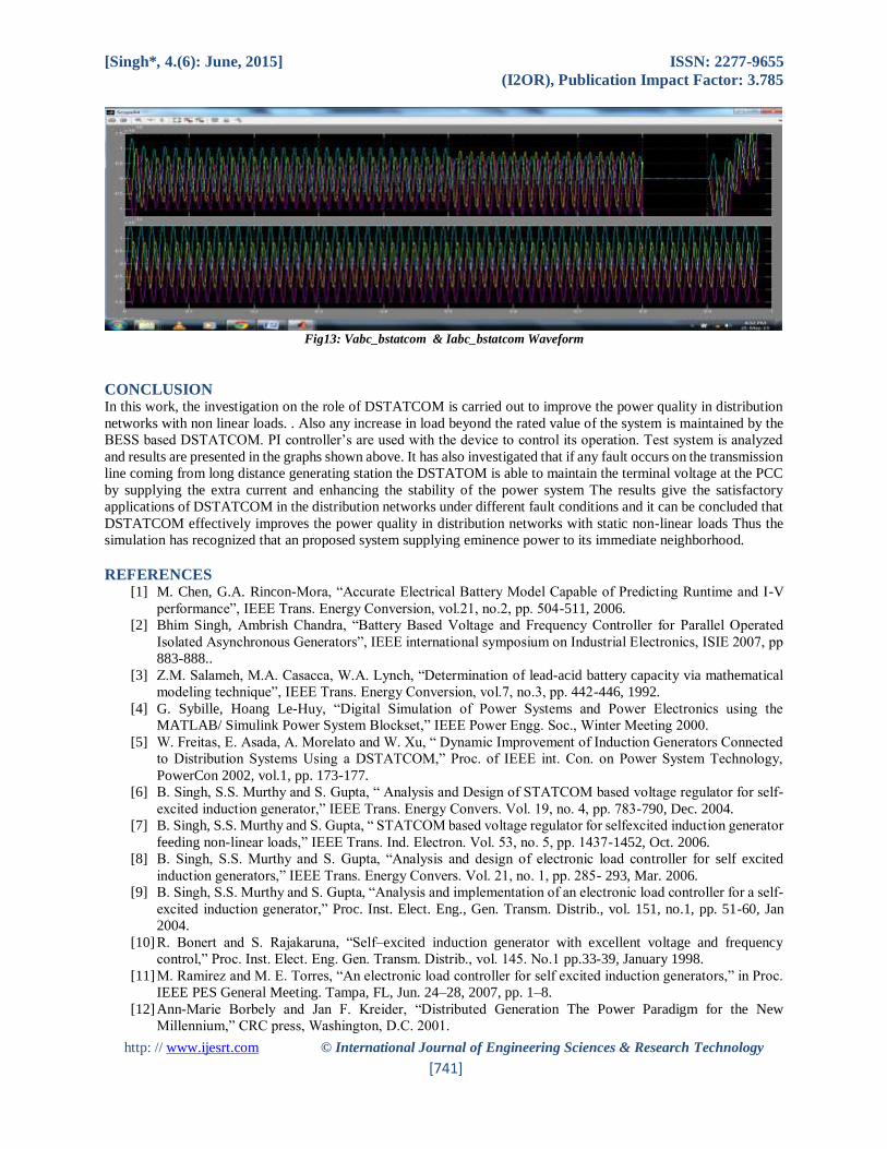
this fault is shown by increase in the bus current (Iabc7). At 0.6 s this fault is unswitched. The DSTATCOM steps in
and Supplies the extra current requirement and prevents the voltage at PCC from falling. From 0.8s to 0.9s a phase to
ground short circuit fault is simulated on the PCC. Though Disorder is observed and DSTATCOM supplies the
necessary reactive current and prevents the PCC voltage from collapsing. Throughout the whole simulation as the
total load on the generators of the system is maintained constant by the DSTATCOM the speed of the generators
remain constant at around 1450 rpm
Fig7: Speed curves of SEIG Generator 1 and SEIG Generator 2
Fig8: Voltage & Current waveform of DSTATCOM
Fig9: Voltage & Current waveform of SEIG Generator 1

[Singh*, 4.(6): June, 2015] ISSN: 2277-9655
(I2OR), Publication Impact Factor: 3.785
http: // www.ijesrt.com © International Journal of Engineering Sciences & Research Technology
[740]
Fig10: Voltage & Current waveform of SEIG Generator 2
Fig11: Current & Voltage Waveform of load 1(8KW) and double loading by Load 3(8KW)
Fig 12: Current & Voltage Waveform of Load 2 (4KW) and three phase fault inserted at transmission line and PCC
[Singh*, 4.(6): June, 2015] ISSN: 2277-9655
(I2OR), Publication Impact Factor: 3.785
http: // www.ijesrt.com © International Journal of Engineering Sciences & Research Technology
[741]
Fig13: Vabc_bstatcom & Iabc_bstatcom Waveform
CONCLUSION In this work, the investigation on the role of DSTATCOM is carried out to improve the power quality in distribution
networks with non linear loads. . Also any increase in load beyond the rated value of the system is maintained by the
BESS based DSTATCOM. PI controller’s are used with the device to control its operation. Test system is analyzed
and results are presented in the graphs shown above. It has also investigated that if any fault occurs on the transmission
line coming from long distance generating station the DSTATOM is able to maintain the terminal voltage at the PCC
by supplying the extra current and enhancing the stability of the power system The results give the satisfactory
applications of DSTATCOM in the distribution networks under different fault conditions and it can be concluded that
DSTATCOM effectively improves the power quality in distribution networks with static non-linear loads Thus the
simulation has recognized that an proposed system supplying eminence power to its immediate neighborhood.
REFERENCES [1] M. Chen, G.A. Rincon-Mora, “Accurate Electrical Battery Model Capable of Predicting Runtime and I-V
performance”, IEEE Trans. Energy Conversion, vol.21, no.2, pp. 504-511, 2006.
[2] Bhim Singh, Ambrish Chandra, “Battery Based Voltage and Frequency Controller for Parallel Operated
Isolated Asynchronous Generators”, IEEE international symposium on Industrial Electronics, ISIE 2007, pp
883-888..
[3] Z.M. Salameh, M.A. Casacca, W.A. Lynch, “Determination of lead-acid battery capacity via mathematical
modeling technique”, IEEE Trans. Energy Conversion, vol.7, no.3, pp. 442-446, 1992.
[4] G. Sybille, Hoang Le-Huy, “Digital Simulation of Power Systems and Power Electronics using the
MATLAB/ Simulink Power System Blockset,” IEEE Power Engg. Soc., Winter Meeting 2000.
[5] W. Freitas, E. Asada, A. Morelato and W. Xu, “ Dynamic Improvement of Induction Generators Connected
to Distribution Systems Using a DSTATCOM,” Proc. of IEEE int. Con. on Power System Technology,
PowerCon 2002, vol.1, pp. 173-177.
[6] B. Singh, S.S. Murthy and S. Gupta, “ Analysis and Design of STATCOM based voltage regulator for self-
excited induction generator,” IEEE Trans. Energy Convers. Vol. 19, no. 4, pp. 783-790, Dec. 2004.
[7] B. Singh, S.S. Murthy and S. Gupta, “ STATCOM based voltage regulator for selfexcited induction generator
feeding non-linear loads,” IEEE Trans. Ind. Electron. Vol. 53, no. 5, pp. 1437-1452, Oct. 2006.
[8] B. Singh, S.S. Murthy and S. Gupta, “Analysis and design of electronic load controller for self excited
induction generators,” IEEE Trans. Energy Convers. Vol. 21, no. 1, pp. 285- 293, Mar. 2006.
[9] B. Singh, S.S. Murthy and S. Gupta, “Analysis and implementation of an electronic load controller for a self-
excited induction generator,” Proc. Inst. Elect. Eng., Gen. Transm. Distrib., vol. 151, no.1, pp. 51-60, Jan
2004.
[10] R. Bonert and S. Rajakaruna, “Self–excited induction generator with excellent voltage and frequency
control,” Proc. Inst. Elect. Eng. Gen. Transm. Distrib., vol. 145. No.1 pp.33-39, January 1998.
[11] M. Ramirez and M. E. Torres, “An electronic load controller for self excited induction generators,” in Proc.
IEEE PES General Meeting. Tampa, FL, Jun. 24–28, 2007, pp. 1–8.
[12] Ann-Marie Borbely and Jan F. Kreider, “Distributed Generation The Power Paradigm for the New
Millennium,” CRC press, Washington, D.C. 2001.

[Singh*, 4.(6): June, 2015] ISSN: 2277-9655
(I2OR), Publication Impact Factor: 3.785
http: // www.ijesrt.com © International Journal of Engineering Sciences & Research Technology
[742]
[13] R.C. Bansal, T.S. Bhatti, and D. P. Kothari, “Bibliography on the application of induction generator in non
conventional energy systems,” IEEE Trans. Energy Convers., vol. EC-18, no. 3, pp. 433–439, Sep. 2003.
[14] Ropp, M.E. Gonzalez, S. ―Development of a MATLAB/Simulink Model of a Single-Phase Grid-Connected
Photovoltaic System‖, Dept of Electr. Eng., South Dakota State Univ., Brookings, SD, February 2009, pp.
195 – 202.
Related Documents