UNCLASSIFIED UNCLASSIFIED American Institute of Aeronautics and Astronautics 1 Use of a Conceptual Sizing Tool for Conceptual Design of Tactical Missiles (U) Andrew P. Frits ∗ , Eugene L. Fleeman † , and Dimitri N. Mavris ‡ Aerospace Systems Design Laboratory School of Aerospace Engineering Georgia Institute of Technology Atlanta, GA 30332-0150 ABSTRACT†‡ This paper illustrates the use of a conceptual sizing tool for the design of tactical mis siles. The sizing tool, called the Tactical Missile Design (TMD) spreadsheet, was developed to allow the user to quickly generate estimates of a missile configuration’s performance and other measures of m erit such as lethality. This capability allows the user to get a first order estimate of a missile’s ability to meet a set of requirements and allows for fast trade-studies to quickly identify the performance drive rs of a system. In order to generate reasonable estimates for missile range and speed, a sizing tool must have analysis methods for aerodynamics, propulsion, weight, and trajectory. In order for the sizing t ool to remain useful for conceptual tradeoffs, these analyses must be robust enough to handle a wide range of inputs, yet simple enough to be executed quick ly. The analysis methods were constructed with these requirem ents in mind. The aerodynamics analysis is based upon several physics- derived analytical expressions as outlined in the text “Tactical Missile Design” by Eugene Fleeman. Propulsion uses a simplified cycle analysis to relate engine parameters (maximum inlet temperature, fuel heating value, expansion ratio) to overall specific impulse (I sp ). The propulsion analysis can handle either air-breathing and solid-rocket systems, or a combination t hereof. For tr ajectory, a constant fl ight path is assumed, with a boost, cruise, and coast phase. These straightforward analysis methods combine to produce a very powerful, yet robust, conceptual missile design tool. ∗ Graduate Research Assistant, Aerospace Systems Design Laboratory † Missile Systems Technical Lead, Aerospace Systems Design Laboratory ‡ Director, Aerospace Systems Design Laboratory, Boeing Prof. Copyright © 200 2 by Dimitri Mavris. Published by the Defense Technical Information Center, with permission. Presented at 2002 Missile Sciences Conference, Monterey, CA. DISTRUBUTION STATEMENT: UNCLASSIFIED; Approved for public release; distribu tion is unlimited The paper first lays out the analysis methods, assumptions, and limitations in the Tactical Missile Design spreadsheet. Next, a c omparison is made between the results of the TMD spreadsheet and the performance of historical missile systems. In addition, the paper explores some example trade studies to identify the drivers of a rocket and a ramjet missile system. Finally, the T MD spreadsheet is used to show how easily a tactical missile can be optimized at the conceptual level. INTRODUCTION In early stages of conceptual design, sizing tools are needed that allow for quick tradeoffs among design parameters. For greatest effectiveness, these sizing tools must meet three requirements, they must accept wide variations in the first order parameters of components, they must accurately show the effects of parameter variation, and they must be capable of rapid, economical analysis 1 . Rapid analysis is required in conceptual design because the multi-dimensional nature of the design problem often results in a need to examine literally thousands of potential system configurations. In the case of missile design, a tool is needed that can analyze a missile with a set of geometry, structural, and propulsion parameters and calculate the missile performance. In this case, the performance of the system may be summarized by the missile range, maximum velocity, and tim e-to-target. In many cases, these performance characteristics can be calculated from fir st-order, p hysics-based anal yses. Often, t hese analyses can be represented in terms of straightforward analytical expressions that allow for easy calculation. The elegance of this approach is that with the linking of reasonably simple analytical expressions from multiple disciplines, a very powerful, yet useable tool can be developed that gives very fast and reasonably good estimates of missile system performance. A spreadsheet developed in Microsoft Excel was used as the framework for this conceptual sizing tool. Microsoft Excel was chosen because of its wide availability and familiarity among both engineers and managers. Furthermore, Excel has all the functionality needed to handle t he required calcul ations. Excel also

Welcome message from author
This document is posted to help you gain knowledge. Please leave a comment to let me know what you think about it! Share it to your friends and learn new things together.
Transcript
8/10/2019 Use of a Conceptual Sizing Tool for Conc
http://slidepdf.com/reader/full/use-of-a-conceptual-sizing-tool-for-conc 1/11
UNCLASSIFIED
UNCLASSIFIED
American Institute of Aeronautics and Astronautics1
Use of a Conceptual Sizing Tool for Conceptual Design of Tactical Missiles (U)
Andrew P. Frits∗, Eugene L. Fleeman†, and Dimitri N. Mavris‡
Aerospace Systems Design LaboratorySchool of Aerospace Engineering
Georgia Institute of TechnologyAtlanta, GA 30332-0150
ABSTRACT†‡
This paper illustrates the use of a conceptual sizing tool
for the design of tactical missiles. The sizing tool,called the Tactical Missile Design (TMD) spreadsheet,
was developed to allow the user to quickly generate
estimates of a missile configuration’s performance andother measures of merit such as lethality. This
capability allows the user to get a first order estimate ofa missile’s ability to meet a set of requirements and
allows for fast trade-studies to quickly identify the
performance drivers of a system.
In order to generate reasonable estimates for missilerange and speed, a sizing tool must have analysis
methods for aerodynamics, propulsion, weight, and
trajectory. In order for the sizing tool to remain useful
for conceptual tradeoffs, these analyses must be robustenough to handle a wide range of inputs, yet simple
enough to be executed quickly. The analysis methods
were constructed with these requirements in mind. Theaerodynamics analysis is based upon several physics-
derived analytical expressions as outlined in the text
“Tactical Missile Design” by Eugene Fleeman.Propulsion uses a simplified cycle analysis to relate
engine parameters (maximum inlet temperature, fuelheating value, expansion ratio) to overall specific
impulse (Isp). The propulsion analysis can handle either
air-breathing and solid-rocket systems, or acombination thereof. For trajectory, a constant flight
path is assumed, with a boost, cruise, and coast phase.
These straightforward analysis methods combine to produce a very powerful, yet robust, conceptual missile
design tool.
∗ Graduate Research Assistant, Aerospace Systems Design
Laboratory † Missile Systems Technical Lead, Aerospace Systems Design
Laboratory ‡ Director, Aerospace Systems Design Laboratory, Boeing Prof.
Copyright © 2002 by Dimitri Mavris. Published by the DefenseTechnical Information Center, with permission. Presented at 2002
Missile Sciences Conference, Monterey, CA.DISTRUBUTION STATEMENT: UNCLASSIFIED;
Approved for public release; distribution is unlimited
The paper first lays out the analysis methods,
assumptions, and limitations in the Tactical Missile
Design spreadsheet. Next, a comparison is made
between the results of the TMD spreadsheet and the performance of historical missile systems. In addition,
the paper explores some example trade studies to
identify the drivers of a rocket and a ramjet missilesystem. Finally, the TMD spreadsheet is used to show
how easily a tactical missile can be optimized at the
conceptual level.
INTRODUCTION
In early stages of conceptual design, sizing tools are
needed that allow for quick tradeoffs among design
parameters. For greatest effectiveness, these sizingtools must meet three requirements, they must accept
wide variations in the first order parameters of
components, they must accurately show the effects of parameter variation, and they must be capable of rapid,
economical analysis1. Rapid analysis is required in
conceptual design because the multi-dimensional natureof the design problem often results in a need to examine
literally thousands of potential system configurations.
In the case of missile design, a tool is needed that cananalyze a missile with a set of geometry, structural, and
propulsion parameters and calculate the missile
performance. In this case, the performance of the
system may be summarized by the missile range,
maximum velocity, and time-to-target. In many cases,these performance characteristics can be calculated
from first-order, physics-based analyses. Often, these
analyses can be represented in terms of straightforwardanalytical expressions that allow for easy calculation.
The elegance of this approach is that with the linking of
reasonably simple analytical expressions from multipledisciplines, a very powerful, yet useable tool can be
developed that gives very fast and reasonably goodestimates of missile system performance.
A spreadsheet developed in Microsoft Excel was used
as the framework for this conceptual sizing tool.
Microsoft Excel was chosen because of its wide
availability and familiarity among both engineers andmanagers. Furthermore, Excel has all the functionality
needed to handle the required calculations. Excel also
8/10/2019 Use of a Conceptual Sizing Tool for Conc
http://slidepdf.com/reader/full/use-of-a-conceptual-sizing-tool-for-conc 2/11
UNCLASSIFIED
UNCLASSIFIED
American Institute of Aeronautics and Astronautics2
allows for the easy visualization of both interim and
final numbers, thus increasing the overall tractability of
the solution.
This paper first illustrates the Tactical Missile Design
(TMD) spreadsheet, explaining the overall layout and
governing equations. Later the paper looks at potential
uses of the TMD tool, exploring single and thenmultiple dimension case studies. Finally, the paper
explores missile optimization using the Tactical Missile
Design spreadsheet.
TACTICAL MISSILE DESIGN SPREADSHEET
The Tactical Missile Design spreadsheet includesanalyses for many disciplines. These disciplines are:
aerodynamics, propulsion, trajectory, structure,
warhead, radar, and dynamics. These disciplines
include all the required disciplines for a complete
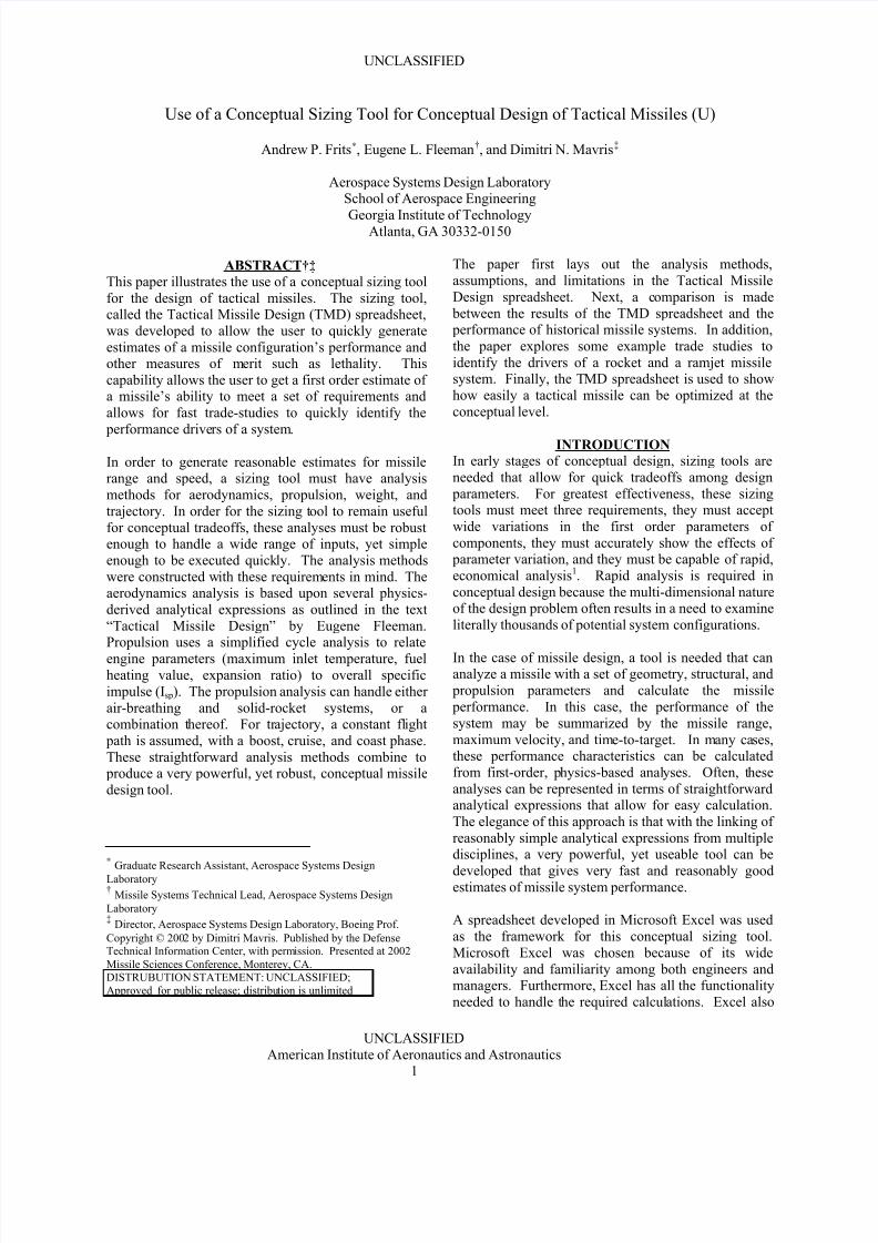
conceptual design process. This process is illustrated inFigure 1. The spreadsheet is constructed so that each
discipline is handled on an individual worksheet. This breakdown allows the user to focus on each disciplineindividually. Linking of the individual
disciplines/worksheets is done through two master
worksheets, one worksheet that is designed to handleuser-inputs and one worksheet that holds results from
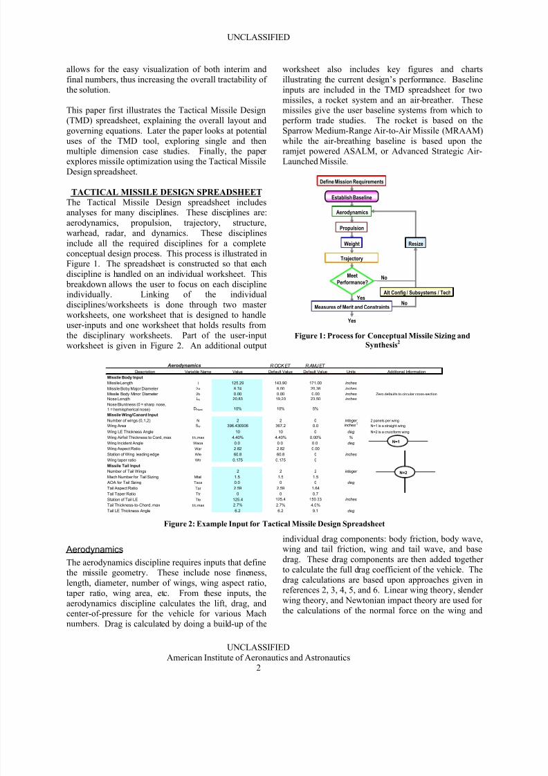
the disciplinary worksheets. Part of the user-input
worksheet is given in Figure 2. An additional output
worksheet also includes key figures and charts
illustrating the current design’s performance. Baseline
inputs are included in the TMD spreadsheet for two
missiles, a rocket system and an air-breather. Thesemissiles give the user baseline systems from which to
perform trade studies. The rocket is based on the
Sparrow Medium-Range Air-to-Air Missile (MRAAM)
while the air-breathing baseline is based upon theramjet powered ASALM, or Advanced Strategic Air-
Launched Missile.
Yes
Define Mission Requirements
Establish Baseline
Aerodynamics
Propulsion
Weight
Trajectory
Resize
Meet
Performance?
Measures of Merit and ConstraintsNo
No
YesAlt Config / Subsystems / Tech
Figure 1: Process for Conceptual Missile Sizing and
Synthesis2
R OCK ET R AMJ ET Description Variable Name Value Default Value Default Value Units
Missile Body Input
Missile Length l 125.29 143.90 171.00 inches
Missile Boby Major Diameter 2a 8.74 8.00 20.38 inches
Missile Body Minor Diameter 2b 0.00 0.00 0.00 inches
Nose Length LN 20.83 19.20 23.50 inches
Nose Bluntness (0 = sharp nose,
1 = hemispherical nose) DHemi 10% 10% 5%
Missile Wing/Canard Input
Number of wings (0,1,2) N 2 2 0 integer 2 panels per wing
Wing Area SW 396.430906 367.2 0.0 inches2
N=1 is a straight wing
Wing LE Thickness Angle 10 10 0 deg N=2 is a cruiciform wing
Wing Airfoil Thickness to Cord, max t/c,max 4.40% 4.40% 0.00% %
Wing Incident Angle Waoa 0.0 0.0 0.0 deg
Wing Aspect Ratio War 2.82 2.82 0.00
Station of Wing leading edge Wle 60.8 60.8 0 inches
Wing taper ratio Wtr 0.175 0.175 0
Missile Tail Input
Number of Tail Wings 2 2 2 integer
Mach Number for Tail Sizing Mtail 1.5 1.5 1.5
AOA for Tail Sizing Taoa 0.0 0 0 deg
Tail Aspect Ratio Tar 2.59 2.59 1.64
Tail Taper Ratio Ttr 0 0 0.7
Station of Tail LE Tle 125.4 125.4 150.33 inches
Tail Thickness-to-Chord, max t/c,max 2.7% 2.7% 4.0%
Tail LE Thickness Angle 6.2 6.2 9.1 deg
Aerodynamics
Additonal Information
Zero defaults to circular cross-section
N=1
N=2
Figure 2: Example Input for Tactical Missile Design Spreadsheet
Aerodynamics
The aerodynamics discipline requires inputs that definethe missile geometry. These include nose fineness,
length, diameter, number of wings, wing aspect ratio,
taper ratio, wing area, etc. From these inputs, the
aerodynamics discipline calculates the lift, drag, andcenter-of-pressure for the vehicle for various Mach
numbers. Drag is calculated by doing a build-up of the
individual drag components: body friction, body wave,wing and tail friction, wing and tail wave, and base
drag. These drag components are then added together
to calculate the full drag coefficient of the vehicle. The
drag calculations are based upon approaches given inreferences 2, 3, 4, 5, and 6. Linear wing theory, slender
wing theory, and Newtonian impact theory are used for
the calculations of the normal force on the wing and

8/10/2019 Use of a Conceptual Sizing Tool for Conc
http://slidepdf.com/reader/full/use-of-a-conceptual-sizing-tool-for-conc 3/11
UNCLASSIFIED
UNCLASSIFIED
American Institute of Aeronautics and Astronautics3
tail. Slender body theory and crossflow theory are used
in the calculations of the normal force on the body3.
In addition to calculations of lift and drag, theaerodynamics section also includes tail sizing. Inputs
such as tail aspect ratio, taper ratio, and distance from
the nose are used to calculate the required tail area for
neutral static stability at a user-specified Mach number.The contributions to drag and lift from the tail are then
included in the total vehicle drag and lift calculations.
An outline of the rocket baseline missile, with the givenwing geometry and appropriately sized tail, is also
provided to the user (see Figure 3).
Missile Outline
(figure NOT to scale)
-30.0
-20.0
-10.0
0.0
10.0
20.0
30.0
0.0 20.0 40.0 60.0 80.0 100.0 120.0 140.0 160.0
Figure 3: Missile Outline with Appropriately Sized Tail
Propulsion
The propulsion discipline is designed to handle a dual-thrust level missile. It has the capability of analyzing
both rockets and air-breathing systems. The first thrust
level is assumed to be a rocket-based boost motor. Forthe rocket, the user inputs the propellant-type,
combustion chamber pressure, burn time, andexpansion ratio. From this data, simple rocket relations
are used to calculate the throat area, exit area, thrust,
and specific impulse. The spreadsheet warns the user
whenever the exit area is greater than the maximum
diameter of the missile.
For the sustain thrust levels, the user selects between an
air-breather and a rocket system. Rocket-based sustain
motors are handled identically to the boost motor. Forthe air-breather, the user selects between several
potential options: turbofan, turbojet, ramjet, or scramjet.
For the turbofan, turbojet, and scramjet systems, a look-up table for Isp versus Mach number is used. However,
for the ramjet, the thrust and Isp are explicitly calculated
using a simple cycle analysis. This analysis takes thefuel type, fuel-to-air ratio, atmospheric and flight
conditions, and an estimated pressure recovery to
calculate the ramjet thrust and Isp. Once the thrust andIsp of the entire vehicle is known, along with the
aerodynamics data, the vehicle trajectory can becalculated.
Trajectory
The trajectory discipline begins by assuming that the
missile flies a constant flight path angle. This type of
flight-path is consistent with that of guided missile
systems. The trajectory is broken into three phases:
boost, sustain, and coast. The spreadsheet includes the
option for the missile to decrease its empty weight between the boost and sustain motors. This decrease
models the discarding of a boost motor or nozzle. To
calculate the trajectory of the missile, the rocket
equation is used to estimate the speed to which therocket/boost motor accelerates the vehicle. This
equation assumes a constant thrust and Isp (provided by
the propulsion discipline). In addition, an average dragover the boost stage is calculated by first calculating the
drag at the initial flight condition, estimating the final
boost velocity, and then calculating the drag at this newflight condition. The drag at the launch and burnout
conditions are averaged together to obtain a drag
estimate for Equation 1.
∆V = -g Isp (1-D/T)*ln (1 - WP / WL) EQ 1
The sustain motor’s portion of the trajectory is handledseparately depending on whether the system is rocket-
based or air-breathing. For a rocket-based system, the
sustain motor is handled identically to the boost motor,
via Equation 1, with a similar estimate made for theaverage drag. For the air-breathing system, the velocity
is assumed to remain constant throughout the cruise-
portion of the flight. The lift-to-drag ratio for this
condition is calculated by the aerodynamics discipline,which determines the required angle-of-attack for the
missile. With the Isp from propulsion and the lift-to-
drag ratio determined by the aerodynamics, the cruiserange of the missile is found using the Breguet Range
Equation (Equation 2).
R = ( L / D ) I sp V In [ WL / ( WL – WP )] ,Breguet Range Equation EQ 2
There are two options in the modeling of the coast
portion of flight. The first option is to continue
assuming a constant flight path angle for the entire
coast phase. This option uses a simple 1-DOF model,with an average drag value, to estimate the time and
distance that the vehicle coasts. It assumes that the
missile will coast down to a threshold Mach number set
by the user. The 1-DOF equations used for the coastcalculations are shown in Equation 3 and Equation 4.
VEC / VBC = 1 / { 1 + tcoast / [ 2 WBO / ( g ρ SRef CD0 VBC )]} EQ 3
Rcoast / [ 2 WBO / ( g ρ SRef CD0 )] =ln {1 + tcoast / [ 2 W / ( g ρ SRef CD0 VBC )]} EQ 4
The second option for the coast portion of flight is to
assume that the vehicle maintains zero angle-of-attackand falls ballistically to a specified altitude. Again,
8/10/2019 Use of a Conceptual Sizing Tool for Conc
http://slidepdf.com/reader/full/use-of-a-conceptual-sizing-tool-for-conc 4/11
UNCLASSIFIED
UNCLASSIFIED
American Institute of Aeronautics and Astronautics4
simple analytical expressions are developed for the
ballistic trajectory which give the time and distance to
impact, along with the impact velocity.
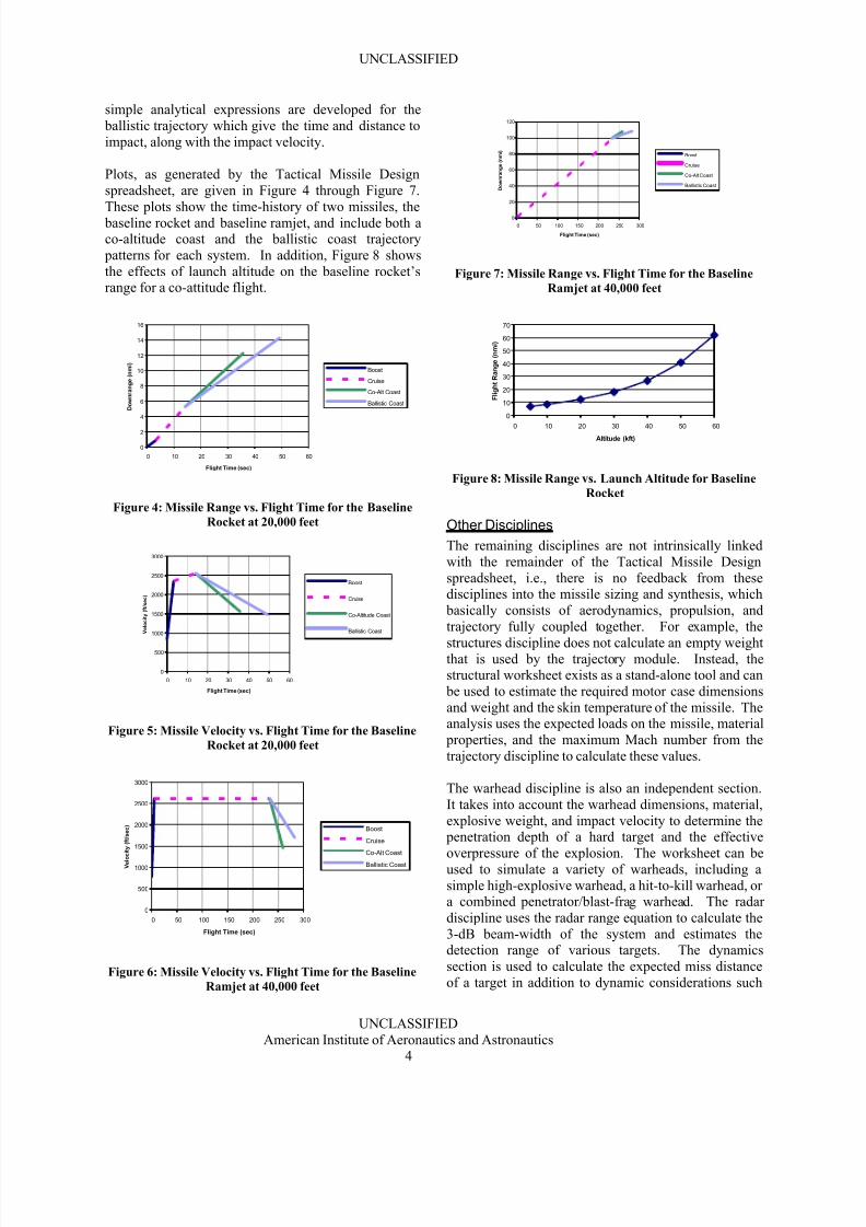
Plots, as generated by the Tactical Missile Design
spreadsheet, are given in Figure 4 through Figure 7.
These plots show the time-history of two missiles, the
baseline rocket and baseline ramjet, and include both aco-altitude coast and the ballistic coast trajectory
patterns for each system. In addition, Figure 8 shows
the effects of launch altitude on the baseline rocket’srange for a co-attitude flight.
0
2
4
6
8
10
12
14
16
0 10 20 30 40 50 60
Flight Time (sec)
D o w n r a n g e ( n m i )
Boost
Cruise
Co-Alt Coast
Ballistic Coast
Figure 4: Missile Range vs. Flight Time for the Baseline
Rocket at 20,000 feet
0
500
1000
1500
2000
2500
3000
0 10 20 30 40 50 60
Flight Time (sec)
V e l o c i t y ( f t / s e c )
Boost
Cruise
Co-Altitude Coast
Ballistic Coast
Figure 5: Missile Velocity vs. Flight Time for the Baseline
Rocket at 20,000 feet
0
500
1000
1500
2000
2500
3000
0 50 100 150 200 250 300
Flight Time (sec)
V e l o c i t y ( f t / s e c )
Boost
Cruise
Co-Alt Coast
Ballistic Coast
Figure 6: Missile Velocity vs. Flight Time for the Baseline
Ramjet at 40,000 feet
0
20
40
60
80
100
120
0 50 100 150 200 250 300
Flight Time (sec)
D o w n r a n g e ( n m i )
Boost
Cruise
Co-Alt Coast
Ballistic Coast
Figure 7: Missile Range vs. Flight Time for the Baseline
Ramjet at 40,000 feet
0
10
20
30
40
50
60
70
0 10 20 30 40 50 60
Altitude (kft)
F l i g h t R a n g e ( n m i )
Figure 8: Missile Range vs. Launch Altitude for Baseline
Rocket
Other Disciplines
The remaining disciplines are not intrinsically linked
with the remainder of the Tactical Missile Design
spreadsheet, i.e., there is no feedback from thesedisciplines into the missile sizing and synthesis, which
basically consists of aerodynamics, propulsion, and
trajectory fully coupled together. For example, the
structures discipline does not calculate an empty weightthat is used by the trajectory module. Instead, thestructural worksheet exists as a stand-alone tool and can
be used to estimate the required motor case dimensions
and weight and the skin temperature of the missile. Theanalysis uses the expected loads on the missile, material
properties, and the maximum Mach number from the
trajectory discipline to calculate these values.
The warhead discipline is also an independent section.
It takes into account the warhead dimensions, material,
explosive weight, and impact velocity to determine the penetration depth of a hard target and the effective
overpressure of the explosion. The worksheet can beused to simulate a variety of warheads, including a
simple high-explosive warhead, a hit-to-kill warhead, ora combined penetrator/blast-frag warhead. The radar
discipline uses the radar range equation to calculate the
3-dB beam-width of the system and estimates thedetection range of various targets. The dynamics
section is used to calculate the expected miss distance
of a target in addition to dynamic considerations such
8/10/2019 Use of a Conceptual Sizing Tool for Conc
http://slidepdf.com/reader/full/use-of-a-conceptual-sizing-tool-for-conc 5/11
UNCLASSIFIED
UNCLASSIFIED
American Institute of Aeronautics and Astronautics5
as horizontal turn radius. Miss distance is calculated by
first estimating the total missile time constant and then
accounting for flight time, target maneuverability, and
initial heading error. The methods for thesecalculations are laid out in References 2, 3, 7, and 8.
VALIDATION
Verification and validation of the Tactical MissileDesign spreadsheet was accomplished through
comparisons with computer analysis codes and actual
test data. For the baseline rocket case, the MRAAMmissile was compared to wind tunnel data and a
computer analysis program: Advanced Design of
Aerodynamics Missiles (ADAM). The results of thiscomparison for one example are shown below, where
for fixed launched conditions, it was desirable to see
how quickly the rocket could travel 6.7 nautical miles at
a flight altitude of 20,000 feet. As Table I shows, the
calculated flight time of the missile and zero-lift dragcoefficient compares well with the computer simulation
(ADAM)9, although there is some discrepancy with thewind tunnel data due to the much higher zero-lift dragcoefficient estimated from the wind tunnel data.
Table I: Comparison of Missile Flight Time and CD0 for
6.7 nmi Flyout
Flight Time (sec) Coast Cdo
ADAM 18 0.53
Wind Tunnel 21 1.05
TMD spreadsheet 17.9 0.59
Table II shows a comparison of a calculated trajectory
from the Tactical Missile Design spreadsheet andMRAAM test data10. Note that the burnout velocity
calculated by the TMD spreadsheet is higher than theactual data, and hence the ranges are higher, but overallthe results compare favorably. Further TMD
comparisons are planned against complete MRAAM
and other missile wind tunnel data.
Table II: Comparison of TMD Predicted Missile Flight
Time with Test Data
Burnout
Vel
(ft/sec)
Burnout
Range
(nmi)
Total
Range
(nmi)
Test Data 2147 4.5 9
TMD spreadsheet 2488 5.04 11.6
ONE DIMENSION CASE STUDY
The Tactical Missile Design spreadsheet allows for theuser to easily perform trade-studies. By changing input
cells manually and tracking the results, the user can
quickly do one-dimensional trade studies, searching forthe optimal setting of any variable. The TMD
spreadsheet was explicitly designed to give the user this
type of capability. A quick example of this type of one-dimensional case study is given below. From the
ramjet baseline system, the missile outer diameter was
varied from the original value of 20.38 inches to a
minimum of 14 inches and a maximum of 24 inches.
The total volume of the missile was held constant, so
the length increased as the diameter decreased. Naturally, this type of length to diameter relationship
would be contingent upon the subsystems being
packageable into a smaller diameter missile and the
missile maintaining launcher compatibility; but therelationship is sufficient for this level of analysis. A
few key response parameters that were tracked are
listed in Table III.
Table III: Case Study with Varying Missile Diameter
Baseline
Missile Diameter (in) 14 16 18 20 20.38 22 24
Burnout Mach 2.78 2.77 2.74 2.71 2.71 2.67 2.63
Flight Range (nmi) 257.7 195.4 148.2 113.5 108.0 88.2 69.7
Flight Time (sec) 601 459 351 272 259 214 172
Horizontal Turn Rad (ft) 14956 15471 15556 15296 15215 14783 14105
The results from the quick study can be represented
graphically, as seen in Figure 9 and Figure 10. Fromthese figures it is readily apparent that decreasing the
diameter greatly enhances the maximum range of the
missile. In addition, the user can see that the turn
radius is benefited by either a large or small diameter, but for diameters near the baseline the turn radius
performs poorly. These type of simple trade-offs can
be readily made in the Tactical Missile Design
spreadsheet environment.
0
50
100
150
200
250
300
0 5 10 15 20 25 30
Missile Diameter (in)
F l i g h t R a n g
e ( n m i )
Figure 9: Variation of Flight Range with Missile
Diameter
14000
14400
14800
15200
15600
16000
0 5 10 15 20 25 30
Missile Diameter (in)
T u r n
R a d i u s ( f t )
Figure 10: Variation of Missile Turn Radius with
Diameter
8/10/2019 Use of a Conceptual Sizing Tool for Conc
http://slidepdf.com/reader/full/use-of-a-conceptual-sizing-tool-for-conc 6/11
UNCLASSIFIED
UNCLASSIFIED
American Institute of Aeronautics and Astronautics6
MULTI-DIMENSIONAL CASE STUDY
The next study was accomplished by parametrically
varying multiple design parameters. Seven design
variables were chosen for this exploration, they arelisted in Table IV. The ranges of the variables used in
the study are also shown in the table. In order to study
the effects of these variations, a full factorial Design of
Experiments was used. A Design of Experiments, usedhere, is a statistical mechanism that identifies which
experimental runs should be made to capture the most
response behavior for the fewest number of totalexperimental runs11. For this application, an
experimental run consists of a single setting of each of
the design variables in the spreadsheet. In the study,129 full-factorial runs were made, along with 21
random runs which were made by randomly setting
each design variable. The results of these variations
were tracked for 10 design outputs. The outputs
tracked are given in Table V, along with the resultsfrom the rocket baseline and the minimum and
maximum parameter values achieved in the study. Note that by no means did this study use acomprehensive set of design variables or outputs.
Several other variables, such as propellant weight,
could also have been used. These variables weresimply chosen to be illustrative of the techniques and
capabilities of the TMD spreadsheet.
Table IV: Ranges of Design Parameters in Parametric
Study
Launch
Weight
(lbm)
Diameter
(in)
Nose
Length
(in)
Wing
Area
(in2)
Expansion
Ratio
Boost
Chamber
Pressure
(psi)
Sustain
Chamber
Pressure
(psi)
Rocket Baseline 500 8 19.2 367.2 6 1769 300
Minimum 400 8 19 367.2 6 1769 300
Maximum 500 12 25 400 15 2500 1000
Table V: Minimum and Maximum Responses from Case
Study
Final
Weight
(lbm)
Maximum
Velocity
(ft/sec)
Burnout
Range
(nmi)
Final
Range
(nmi)
Final
Time
(sec)
Coast
Cd0
Boost Isp
(sec)
Sustain
Isp
(sec)
Horiz
Turn
Radius
(ft)
Rocket Baseline 367 2537.7 5.22 12.06 35.24 0.607 270.5 252 4181
Smallest Response 267 2235 4.11 1.89 3.28 0.488 271 237 3160
Largest Response 367 2878 6.18 14.62 40.90 0.761 286 276 4218
One advantage of running a multi-dimensional study is
that the primary drivers for each system level response,
or performance metric, can be calculated. This conceptis commonly referred to as the “Pareto Principle”,
which states that 80% of the response of the system is
driven by only 20% of the variables. In general, this
principle holds for most system responses, indicatingthat in general, only a few of the design variables tend
to drive most of the variation in any one metric12. A
statistical software package, JMP, was used to analyze
the data from the 150 cases in this study. This software
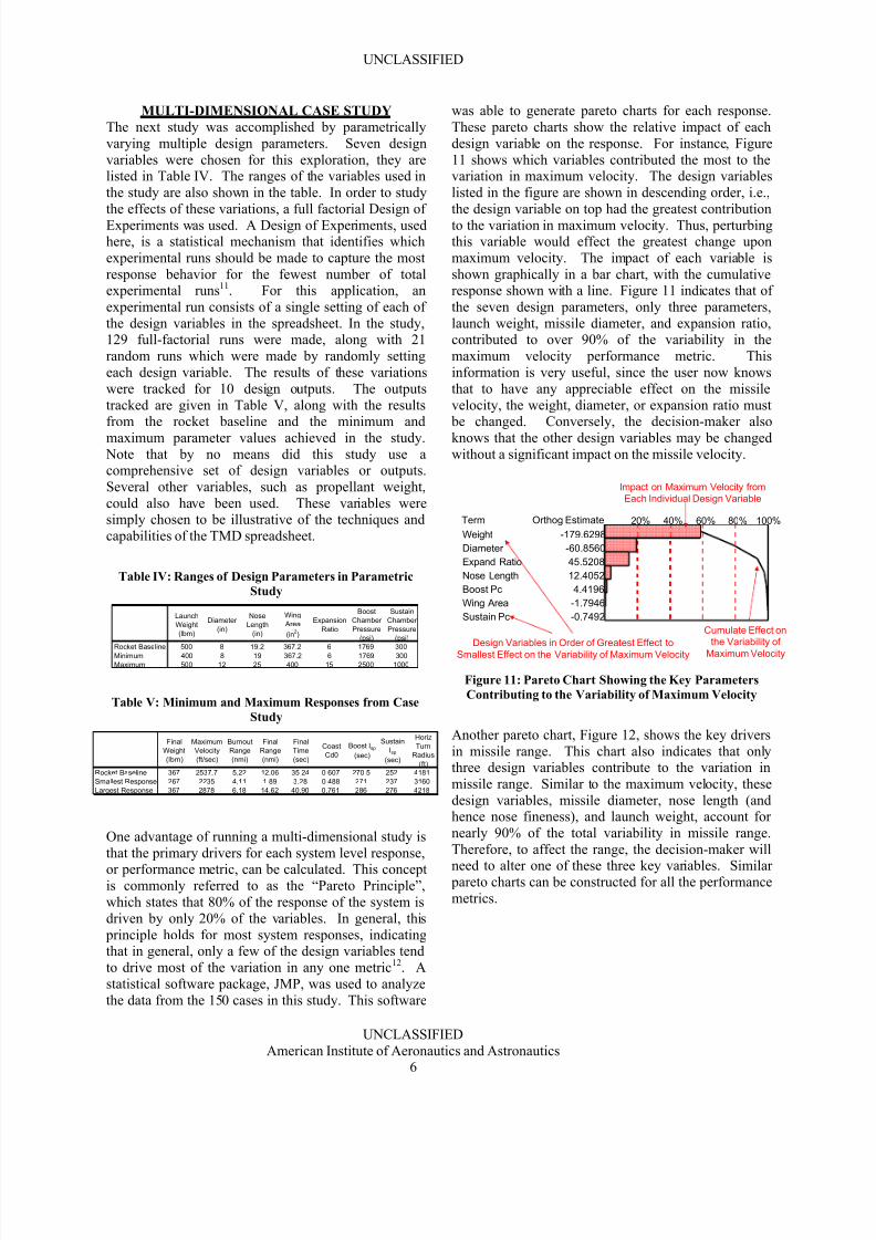
was able to generate pareto charts for each response.
These pareto charts show the relative impact of each
design variable on the response. For instance, Figure
11 shows which variables contributed the most to thevariation in maximum velocity. The design variables
listed in the figure are shown in descending order, i.e.,
the design variable on top had the greatest contribution
to the variation in maximum velocity. Thus, perturbingthis variable would effect the greatest change upon
maximum velocity. The impact of each variable is
shown graphically in a bar chart, with the cumulativeresponse shown with a line. Figure 11 indicates that of
the seven design parameters, only three parameters,
launch weight, missile diameter, and expansion ratio,contributed to over 90% of the variability in the
maximum velocity performance metric. This
information is very useful, since the user now knows
that to have any appreciable effect on the missile
velocity, the weight, diameter, or expansion ratio must be changed. Conversely, the decision-maker also
knows that the other design variables may be changedwithout a significant impact on the missile velocity.
Weight
Diameter
Expand Ratio
Nose Length
Boost Pc
Wing Area
Sustain Pc
Term
-179.6298
-60.8560
45.5208
12.4052
4.4196
-1.7946
-0.7492
Orthog Estimate
Cumulate Effect on
the Variability of
Maximum Velocity
Impact on Maximum Velocity from
Each Individual Design Variable
Design Variables in Order of Greatest Effect to
Smallest Effect on the Variability of Maximum Velocity
20% 40% 80%60% 100%
Figure 11: Pareto Chart Showing the Key Parameters
Contributing to the Variability of Maximum Velocity
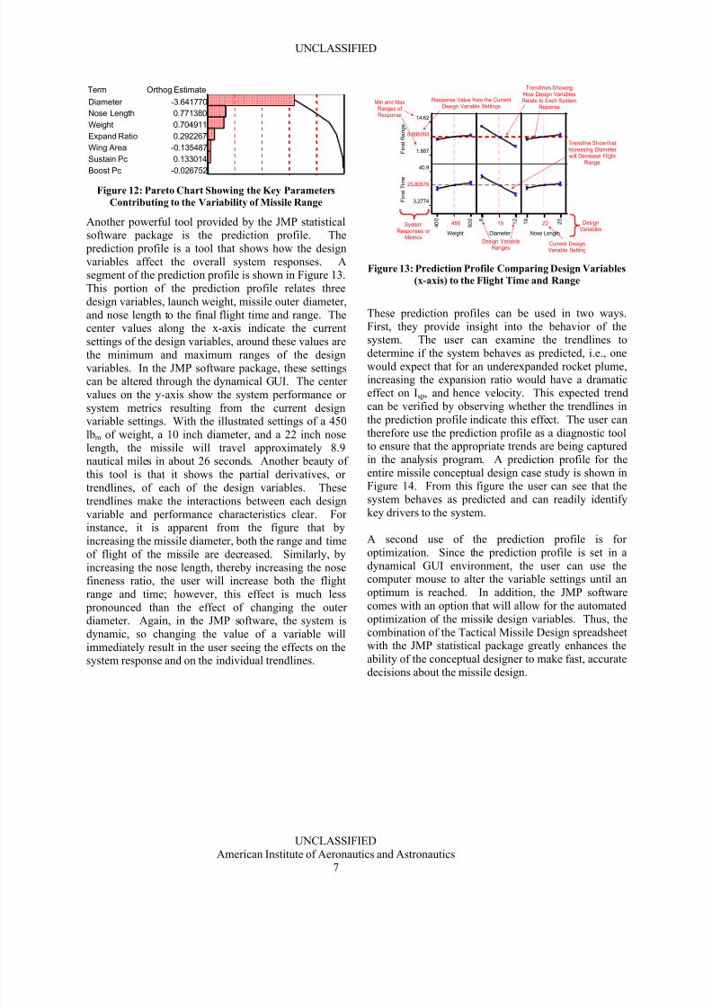
Another pareto chart, Figure 12, shows the key drivers
in missile range. This chart also indicates that onlythree design variables contribute to the variation in
missile range. Similar to the maximum velocity, these
design variables, missile diameter, nose length (andhence nose fineness), and launch weight, account for
nearly 90% of the total variability in missile range.
Therefore, to affect the range, the decision-maker will
need to alter one of these three key variables. Similar pareto charts can be constructed for all the performance
metrics.
8/10/2019 Use of a Conceptual Sizing Tool for Conc
http://slidepdf.com/reader/full/use-of-a-conceptual-sizing-tool-for-conc 7/11
UNCLASSIFIED
UNCLASSIFIED
American Institute of Aeronautics and Astronautics7
Diameter
Nose Length
Weight
Expand Ratio
Wing Area
Sustain Pc
Boost Pc
Term
-3.641770
0.771380
0.704911
0.292267
-0.135487
0.133014
-0.026752
Orthog Estimate
Figure 12: Pareto Chart Showing the Key Parameters
Contributing to the Variability of Missile Range
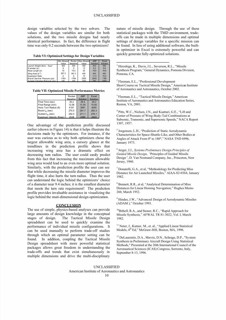
Another powerful tool provided by the JMP statisticalsoftware package is the prediction profile. The
prediction profile is a tool that shows how the design
variables affect the overall system responses. Asegment of the prediction profile is shown in Figure 13.
This portion of the prediction profile relates three
design variables, launch weight, missile outer diameter,
and nose length to the final flight time and range. Thecenter values along the x-axis indicate the current
settings of the design variables, around these values are
the minimum and maximum ranges of the designvariables. In the JMP software package, these settingscan be altered through the dynamical GUI. The center
values on the y-axis show the system performance or
system metrics resulting from the current designvariable settings. With the illustrated settings of a 450
lbm of weight, a 10 inch diameter, and a 22 inch nose
length, the missile will travel approximately 8.9nautical miles in about 26 seconds. Another beauty of
this tool is that it shows the partial derivatives, or
trendlines, of each of the design variables. These
trendlines make the interactions between each design
variable and performance characteristics clear. For
instance, it is apparent from the figure that byincreasing the missile diameter, both the range and time
of flight of the missile are decreased. Similarly, by
increasing the nose length, thereby increasing the nosefineness ratio, the user will increase both the flight
range and time; however, this effect is much less
pronounced than the effect of changing the outerdiameter. Again, in the JMP software, the system is
dynamic, so changing the value of a variable will
immediately result in the user seeing the effects on thesystem response and on the individual trendlines.
F i n a l R a n g e
14.62
1.887
8.896093
F i n a l T i m e
40.9
3.2774
25.80575
Weight
4 0 0
5 0 0
450
Diameter
8 1 2
10
Nose Length
1 9
2 5
22SystemResponses or
Metrics
DesignVariables
Design VariableRanges
Current DesignVariable Setting
Response Value from the CurrentDesign Variable Settings
Min and MaxRanges ofResponse
Trendlines ShowingHow Design VariablesRelate to Each System
Reponse
Trendline Show thatIncreasing Diameterwill Decrease Flight
Range
Figure 13: Prediction Profile Comparing Design Variables
(x-axis) to the Flight Time and Range
These prediction profiles can be used in two ways.
First, they provide insight into the behavior of thesystem. The user can examine the trendlines to
determine if the system behaves as predicted, i.e., onewould expect that for an underexpanded rocket plume,increasing the expansion ratio would have a dramatic
effect on Isp, and hence velocity. This expected trend
can be verified by observing whether the trendlines in
the prediction profile indicate this effect. The user can
therefore use the prediction profile as a diagnostic toolto ensure that the appropriate trends are being captured
in the analysis program. A prediction profile for the
entire missile conceptual design case study is shown inFigure 14. From this figure the user can see that the
system behaves as predicted and can readily identify
key drivers to the system.
A second use of the prediction profile is for
optimization. Since the prediction profile is set in a
dynamical GUI environment, the user can use thecomputer mouse to alter the variable settings until an
optimum is reached. In addition, the JMP software
comes with an option that will allow for the automated
optimization of the missile design variables. Thus, the
combination of the Tactical Missile Design spreadsheetwith the JMP statistical package greatly enhances the
ability of the conceptual designer to make fast, accurate
decisions about the missile design.

8/10/2019 Use of a Conceptual Sizing Tool for Conc
http://slidepdf.com/reader/full/use-of-a-conceptual-sizing-tool-for-conc 8/11
UNCLASSIFIED
UNCLASSIFIED
American Institute of Aeronautics and Astronautics8
H o r i z T u r n R a d i u s 4218
3160.4
3730.217
B o o s t I s p
286.1
270.5
279.9922
S u s t a i n I s p
277.1
237.12
268.4673
M a x i m u m V e l o c i t y 2878
2234.5
2539.112
F i n a l R a n g e
14.62
1.887
8.896093
F i n a l T i m e
40.9
3.2774
25.80575
Weight
4 0 0
5 0 0
450
Diameter
8 1 2
10
Nose Length
1 9
2 5
22
Wing Area 3 6 7 . 2
4 0 0
380
Expand Ratio
6 1 5
10
Boost Pc 1 7 6 9
2 5 0 0
2100
Sustain Pc
3 0 0
1 0 0 0
650
Figure 14: Prediction Profile for the Missile Showing the Linkages between Design Variables and System Responses
MONTE CARLO STUDY
Another application that can be combined with the
Tactical Missile Design spreadsheet is called CrystalBall. Crystal Ball is an add-in for Microsoft Excel. It
can be used to run a Monte Carlo simulation over
various cells, or inputs, and track the response of the
output cells. These Monte Carlo studies are useful inconceptual design because they can illustrate for the
user what type of performance can be achieved with the
system13.
Continuing with the previous example, a Monte Carlosimulation was run by altering the seven design
variables that were used for the multi-dimensional casestudy given in Table IV. These variables were varied
within the ranges shown in the table. A random value
of each design variable was taken for each Monte Carlo
trial, with 10,000 separate trials made over the variableranges. The same outputs as the previous study, those
listed in Table V, were also tracked in this study.
Figure 15 is the probability density function (PDF) for
one of the missile outputs, the maximum Mach number;it shows how many of the 10,000 random cases resulted
in a given Mach number. The figure shows that there
were very few cases that had Mach numbers near 2.2
and very few cases that had Mach numbers near 2.7, butthere was a flat distribution of Mach numbers between
2.3 and 2.6. The user can gleam from this information
that only a few combinations of design variables resultin Mach numbers near 2.2 and 2.7, but there is a wide
range of design variables that can be chosen to generatea maximum Mach number anywhere within the range
of 2.3 to 2.6. Therefore, using these design variables, adecision-maker would expect to have difficulty
designing a missile to have a Mach number matching
these extreme values but relatively little difficulty
designing a system to meet one of the intermediateMach numbers.

8/10/2019 Use of a Conceptual Sizing Tool for Conc
http://slidepdf.com/reader/full/use-of-a-conceptual-sizing-tool-for-conc 9/11
UNCLASSIFIED
UNCLASSIFIED
American Institute of Aeronautics and Astronautics9
0
50100
150200
250
2.19 2.29 2.40 2.51 2.62 2.72
Mach Number
F r e q u
e n c y
Few combinations of design variables
led to extreme Mach numbers
Flat distribution of
Mach numbers
Number of responses out
of 10,000 trials
0
50100
150200
250
2.19 2.29 2.40 2.51 2.62 2.72
Mach Number
F r e q u
e n c y
Few combinations of design variables
led to extreme Mach numbers
Flat distribution of
Mach numbers
Number of responses out
of 10,000 trials
Figure 15: PDF Showing the Number of Responses for
each Mach Number
Perhaps more useful than the PDF is the cumulative
distribution function (CDF) shown in Figure 16 for the
missile Mach number. The CDF shows what percent of
the design space meets a given value or constraint14
.For the example shown, approximately 30% of the
designs, or 30% of the total design space, satisfies ahypothetical constraint for maximum Mach number
greater than 2.5. By using this Monte Carlo technique
in conjunction with the Tactical Missile Design
spreadsheet, even with large numbers of variables (10-
30 or more), the user can get a feel for what type of performance is possible for the system and the
difficulty in meeting constraints.
0%
10%
20%
30%
40%
50%
60%
70%
80%
90%
100%
2.19 2.29 2.40 2.51 2.62 2.72
Mach Number
F r e q u e n c y
Mach > 2.5
constraint
Approximately 30% of all possibledesigns meet this Mach > 2.5 constraint
Feasible
Design
Space
Figure 16: CDF Showing the Portion of the Design Space
that exceeds each Mach Number Value
Another example of a Monte Carlo response is given inFigure 17. This figure shows the response for turn
radius. If a hypothetical constraint was given to themissile designer that required a turn radius less than
4,000 feet, then the Monte Carlo information informsthe designer that over 90% of all possible design
combinations satisfy this constraint. The designer then
knows that this constraint is not going to be difficult tomeet, unlike the Mach number constraint, where only
30% of potential designs satisfy the constraint.
0%
10%20%
30%
40%
50%
60%
70%
80%
90%
100%
3210 3404 3599 3793 3987 4182
Turn Radius (Feet)
F r e q u e n c y
Turn Radius < 4000
constraint
Approximately 90% of all possib ledesigns meet this turn radius constraint
Figure 17: CDF Showing the Response for Turn Radius
with a 4,000 ft Maximum Constraint
Another important piece of information provided by
Monte Carlo runs is when there are no feasible designs
that satisfy a constraint. For instance, in Figure 17, ifthere was a design constraint of a turn radius less than
3,000 feet, then the designer immediately knows that
this constraint is not feasible. The Monte Carlo results
will have shown that not a single possible designvariable combination satisfies this constraint. The
designer can then go about solving the problem by
relaxing the constraint, increasing the variable ranges,
like increasing the maximum wing area, adding new
design variables such as propellant weight or fuelfraction, or possibly infusing new technologies into the
system such as thrust vector control.
MISSILE OPTIMIZATION
A design problem was posed to illustrate how the
Tactical Missile Design spreadsheet can be used tooptimize missile designs for particular missions. For
the example design problem, the previous designvariables and ranges (Table IV) were used, except for
the missile weight, which was fixed at 500 lbm, i.e., itwas assumed that the user did not have control over
empty weight. The objective of the optimization was to
minimize the flight time of the missile subject to two
constraints, a turn radius less than 4,000 feet and aflight range of at least 10 nautical miles.
Two separate optimizers were used for theoptimization. The first optimizer was the automated
solver that JMP uses in the prediction profile. This
solver was able to minimize the flight time while
meeting the two constraints. The other optimizer wasthe built-in solver function in Microsoft Excel. This
solver is surprisingly powerful and, being a native
feature of Excel, is fully integrated with the TMD
spreadsheet.
The results of the two solvers are shown in Table VI
and Table VII. These results are compared against the baseline MRAAM rocket. Table VI shows the missile
8/10/2019 Use of a Conceptual Sizing Tool for Conc
http://slidepdf.com/reader/full/use-of-a-conceptual-sizing-tool-for-conc 10/11
UNCLASSIFIED
UNCLASSIFIED
American Institute of Aeronautics and Astronautics10
design variables selected by the two solvers. The
values of the design variables are similar for both
solutions, and the two missile designs had nearly
identical performance. In fact, the difference in flighttime was only 0.2 seconds between the two optimizers!
Table VI: Optimized Settings for Design VariablesMin Allowed
Value
Rocket
Baseline
Max Allowed
Value
JMP
Solution
Excel
SolutionLaunch Weight (lbm) - fixed 500 500 500 500 500
Diameter (in) 8 8 12 9.2 9.6
Nose Length (in) 19 19.2 25 19.0 19.6
Wing Area (in2) 367.2 367.2 400 400 400
Expansion Ratio 6 6 15 11.3 15.0
Boo st Cha mb er Pressu re (ps i) 1 76 9 1769 2500 2043 1769
Susta in Chamber Pressure (psi) 300 300 1000 742 1000
Table VII: Optimized Missile Performance Metrics
Rocket
Baseline
JMP
Solution
Excel
SolutionFinal Time (sec) 35.2 29.4 29.2
Final Range (nmi) 12.06 10.05 10.00
Horiz Turn Radius (ft) 4181 3991 4000
Boost Isp (sec) 270.5 281.7 283.3
Sustain Isp (sec) 252.0 271.1 276.1
Maximum Velocity (ft/sec) 2538 2385 2443
One advantage of the prediction profile discussed
earlier (shown in Figure 14) is that it helps illustrate the
decisions made by the optimizers. For instance, if the
user was curious as to why both optimizers chose thelargest allowable wing area, a cursory glance at the
trendlines in the prediction profile shows that
increasing wing area has a dramatic effect ondecreasing turn radius. The user could easily predict
from this fact that increasing the maximum allowable
wing area would lead to an even more optimal solution.
Similarly, with the prediction profile the user can seethat while decreasing the missile diameter improves the
flight time, it also hurts the turn radius. Thus the user
can understand the logic behind the optimizers’ choiceof a diameter near 9.4 inches; it is the smallest diameter
that meets the turn rate requirement! The prediction
profile provides invaluable assistance in visualizing the
logic behind the muti-dimensional design optimization.
CONCLUSION
The use of simple, physics-based analyses can provide
large amounts of design knowledge in the conceptualstages of design. The Tactical Missile Design
spreadsheet can be used to quickly examine the
performance of individual missile configurations. Itcan be used manually to perform trade-off studies
through which an optimal parameter setting can be
found. In addition, coupling the Tactical Missile
Design spreadsheet with more powerful statistical packages allows great freedom in understanding the
trade-offs and trends that exist simultaneously in
multiple dimensions and drive the multi-disciplinary
nature of missile design. Through the use of these
statistical packages with the TMD environment, trade-
offs can be made in multiple dimensions and optimal
settings of design variables for a specific mission can be found. In lieu of using additional software, the built-
in optimizer in Excel is extremely powerful and can
quickly generate fully optimized solutions.
1 Hiroshige, K., Davis, J.L., Severson, R.L., “Missile
Synthesis Program,” General Dynamics, Pomona Division,Pomona, CA.
2 Fleeman, E.L., “Professional Development
Short Course on Tactical Missile Design,” American Instituteof Aeronautics and Astronautics, October 2002.
3 Fleeman, E.L., “Tactical Missile Design,” American
Institute of Aeronautics and Astronautics Education Series,Reston, VA, 2001.
4
Pitts, W.C., Nielsen, J.N., and Kaattari, G.E., “Lift andCenter of Pressure of Wing-Body-Tail Combinations atSubsonic, Transonic, and Supersonic Speeds,” NACA Report1307, 1957.
5 Jorgensen, L.H., “Prediction of Static AerodynamicCharacteristics for Space-Shuttle-Like, and Other Bodies at
Angles of Attack From 0° to 180°,” NASA TND 6996,
January 1973.
6 Jerger, J.J., Systems Preliminary Design Principles ofGuided Missile Design, “Principles of Guided Missile
Design”, D. Van Nostrand Company, Inc., Princeton, NewJersey, 1960.
7 Donatelli, G.A., et al, “Methodology for Predicting MissDistance for Air Launched Missiles,” AIAA-82-0364, January1982.
8 Bennett, R.R., et al, “Analytical Determination of Miss
Distances for Linear Homing Navigation,” Hughes Memo260, March 1952.
9 Hindes, J.W., “Advanced Design of Aerodynamic Missiles
(ADAM ),” October 1993.
10Bithell, R.A., and Stoner, R.C., “Rapid Approach forMissile Synthesis,” AFWAL TR 81-3022, Vol. I, March
1982.
11 Neter, J., Kutner, M., et. al., “Applied Linear StatisticalModels, 4th Ed,” McGraw-Hill, Boston, MA, 1996.
12 DeLaurentis, D.A., Mavris, D.N., Schrage, D.P., "SystemSynthesis in Preliminary Aircraft Design Using StatisticalMethods," Presented at the 20th International Council of the
Aeronautical Sciences (ICAS) Congress, Sorrento, Italy,September 8-13, 1996.

8/10/2019 Use of a Conceptual Sizing Tool for Conc
http://slidepdf.com/reader/full/use-of-a-conceptual-sizing-tool-for-conc 11/11
UNCLASSIFIED
UNCLASSIFIED
American Institute of Aeronautics and Astronautics11
13 Mavris, D.N., Mantis, G., Kirby, M.R. Demonstration of aProbabilistic Technique for the Determination of EconomicViability," Presented at the 2nd World Aviation Congress andExposition, Anaheim, CA, October 13-16, 1997.
14 Mavris, D.N., Kirby, M.R., Qiu, S., "Technology Impact
Forecasting for a High Speed Civil Transport," Presented atthe 3rd World Aviation Congress and Exposition, Anaheim,CA, September 28-30, 1998.
Related Documents


![Ongoing AAAR Aerosol MS Tutorial.pptx [Last saved by user]cires.colorado.edu/jimenez/CHEM-5152/Lect/Aerosol_MS.pdfIntro Inlets & Sizing TOFMS Other MS LDI AMS CIMS Conc. CHEM-5152](https://static.cupdf.com/doc/110x72/6015d71eb0c5de08855151f7/ongoing-aaar-aerosol-ms-last-saved-by-usercirescoloradoedujimenezchem-5152lectaerosolmspdf.jpg)


