Welcome message from author
This document is posted to help you gain knowledge. Please leave a comment to let me know what you think about it! Share it to your friends and learn new things together.
Transcript


The use and provision of “cleaner technologies” is the core of climate change mitigation response. While fi-nancial investments in technology research and deve-lopment have generated unprecedented improvements in the way energy is consumed and clean energy sour-ces are tapped, there remains considerable work to effi-ciently and consistently employ these innovative tech-nologies in both developing and developed countries.
The Clean Development Mechanism (CDM) is a bottom-up driven instrument that allows measurable green house gas (GHG) emission reduction possibilities to be proposed formally, through specific procedures and use of approved methodologies by the CDM Executi-ve Board. Technology transfer aside, the CDM has been successful in not only boosting the application of diver-se cleaner technologies that otherwise face financial or technological barriers, but also in facilitating the faster spread of technologies that reduce emissions of green-house gases and that, in many cases, are not currently available or applied in host countries.
As of September 2010, there are 2373 registered projects in the pipeline, applying more than 100 technologies – reducing approximately 1,100,000 KCERs by 2012. Since the beginning of practical operation of the CDM in 2001 (after the adoption of the Marrakech Accords) more than 300 proposals for methodologies to imple-ment and document project based emissions reductions have been proposed to the CDM Executive Board, many of which have been approved. Currently, about 140 me-thodologies are in use – or could be in use, if project pro-ponents used the full methodological potential. Howe-ver, while the bottom-up approach provides ultimate flexibility of the system, it also causes ‘information over-flow’ in the sense that even trained project consultants lose track of the options available to them for presenting their projects in the most efficient way and choosing the best suited methodology.
The UNEP Risoe Centre has followed the development of the CDM since its beginning and updated, on a mon-thly basis, CDM/JI Pipeline Analysis and Database – a web-based database listing all recorded CDM activities and their status of development in the registration pro-cedure, as well as their performance in terms of issuan-ce of certified emissions reductions (CERs). The databa-se categorises projects under 25 types, mainly referring to technologies, and about 140 subtypes of CDM pro-jects, which further divides the technologies into specific areas of application.
The CDM Technology and Methodology Overview aims at providing a more intuitive approach into the wealth
of information contained in the CDM/JI Pipeline. It provides an entry point to identify relevant technologies for GHG emissions reduction from overall defined eco-nomic sectors as it offers a short description of applied or applicable technologies, as well as a few examples of application in the CDM context. As a simple and handy overview it is ideal for a quick review and consultation for general audience, especially for policy makers, to fur-ther the decision making process within a national con-text, in terms of sector prioritization, CDM potentials and design of national strategies (e.g. in long term ener-gy planning). Moreover, this publication provides short-cut guidance on possible CDM methodology choices for each technology, including up-to-date recorded CDM projects combined with their current status in the CDM pipeline. The publication also provides snapshot infor-mation of CDM baseline methodologies both approved and applied as of September 2010.
The CDM Technology and Methodology Overview is de-veloped by the Energy and Carbon Finance Program of the UNEP Risoe Centre, in support of the UNEP Risoe Centre’s Programme for capacity development for the CDM (CD4CDM). With the aim of continuing efforts for easing access of information for a wide audience and bea-ring in mind that the ideal platform for keeping track of technologies and methodologies applicable to different types of projects is a web-based database, this publica-tion is also the basis for a web-based CDM Methodology Selection Tool. Such a platform is currently under deve-lopment and is expected to be launched before the end of 2010. Therefore, this publication is an introduction to this methodology selection database, where additional methodologies not yet applied in any project will be in-cluded – in the hopes of making use of the unexploited work done by project consultants. The web version will also be a platform for continued dialogue among CDM project developers to exchange views and ideas related to the usage of different methodologies. A preliminary version of the CDM methodology selection tool may be found on www.cdm-meth.org.
We hope that this publication will fill the gaps of in-formation and enhance the CDM/JI Pipeline and look forward to interacting with you in the upcoming web-ba-sed Methodology Selection Tool. The UNEP Riseo Cen-tre will appreciate feedback from readers and CDM prac-titioners, which the authors will endeavor to incorporate in the web version.
Miriam Hinostroza,Head of ProgrammeEnergy and Carbon Finance
Preface
3

I. AgricultureandForests . . . . . . . . . . . . . . . . . . . . . . . . . . . . . . . . 6I.1. Forests. . . . . . . . . . . . . . . . . . . . . . . . . . . . . . . . . . . . . . . . . . . . . . 5I.2. Fuels Production . . . . . . . . . . . . . . . . . . . . . . . . . . . . . . . . . . . . . . . . 8
II. Waste . . . . . . . . . . . . . . . . . . . . . . . . . . . . . . . . . . . . . . . . . .10II.1. Agricultural Waste . . . . . . . . . . . . . . . . . . . . . . . . . . . . . . . . . . . . . . 10
II.1.1 Waste from Forest Industry . . . . . . . . . . . . . . . . . . . . . . . . . . . . . . . 11II.1.2 Waste from Other Agricultural Industries. . . . . . . . . . . . . . . . . . . . . . . 13II.1.3 Waste from Palm Oil . . . . . . . . . . . . . . . . . . . . . . . . . . . . . . . . . . 14II.1.4 Waste from Rice Industry . . . . . . . . . . . . . . . . . . . . . . . . . . . . . . . . 15II.1.5 Waste from Sugar Industry . . . . . . . . . . . . . . . . . . . . . . . . . . . . . . . 16
II.2. Liquid Waste . . . . . . . . . . . . . . . . . . . . . . . . . . . . . . . . . . . . . . . . . . 18II.2.1 Manure . . . . . . . . . . . . . . . . . . . . . . . . . . . . . . . . . . . . . . . . . . 19II.2.2 Waste Oil . . . . . . . . . . . . . . . . . . . . . . . . . . . . . . . . . . . . . . . . . 20II.2.3 Wastewater . . . . . . . . . . . . . . . . . . . . . . . . . . . . . . . . . . . . . . . . 21
II.3. Solid Waste. . . . . . . . . . . . . . . . . . . . . . . . . . . . . . . . . . . . . . . . . . . 22II.3.1 Composting . . . . . . . . . . . . . . . . . . . . . . . . . . . . . . . . . . . . . . . . 23II.3.2 Gasification Options . . . . . . . . . . . . . . . . . . . . . . . . . . . . . . . . . . . 25II.3.3 Incineration Options . . . . . . . . . . . . . . . . . . . . . . . . . . . . . . . . . . . 26II.3.4 Landfills. . . . . . . . . . . . . . . . . . . . . . . . . . . . . . . . . . . . . . . . . . 28
III. ConventionalPowerProduction . . . . . . . . . . . . . . . . . . . . . . . . . .30III.1. Efficiency Improvements . . . . . . . . . . . . . . . . . . . . . . . . . . . . . . . . . . 31III.2. Fuel Switch . . . . . . . . . . . . . . . . . . . . . . . . . . . . . . . . . . . . . . . . . . 32III.3. New Systems . . . . . . . . . . . . . . . . . . . . . . . . . . . . . . . . . . . . . . . . . 34
IV. HeatingSystems. . . . . . . . . . . . . . . . . . . . . . . . . . . . . . . . . . . .35IV.1. Efficiency Improvements . . . . . . . . . . . . . . . . . . . . . . . . . . . . . . . . . . 36IV.2. New Systems . . . . . . . . . . . . . . . . . . . . . . . . . . . . . . . . . . . . . . . . . 37
V. RenewableEnergy . . . . . . . . . . . . . . . . . . . . . . . . . . . . . . . . . .38V.1. Biomass. . . . . . . . . . . . . . . . . . . . . . . . . . . . . . . . . . . . . . . . . . . . . 39V.2. Hydro . . . . . . . . . . . . . . . . . . . . . . . . . . . . . . . . . . . . . . . . . . . . . . 42V.3. Wind . . . . . . . . . . . . . . . . . . . . . . . . . . . . . . . . . . . . . . . . . . . . . . . 43V.4. Solar. . . . . . . . . . . . . . . . . . . . . . . . . . . . . . . . . . . . . . . . . . . . . . . 44V.5. Geothermal. . . . . . . . . . . . . . . . . . . . . . . . . . . . . . . . . . . . . . . . . . . 46V.6. Tidal . . . . . . . . . . . . . . . . . . . . . . . . . . . . . . . . . . . . . . . . . . . . . . . 47
Classification
CDM Technology & Methodology Overview 20104
VI. PowerConsumption . . . . . . . . . . . . . . . . . . . . . . . . . . . . . . . . .48VI.1. Buildings. . . . . . . . . . . . . . . . . . . . . . . . . . . . . . . . . . . . . . . . . . . . 49VI.2. Electricity for the Grid . . . . . . . . . . . . . . . . . . . . . . . . . . . . . . . . . . . . 51VI.3. Public Services . . . . . . . . . . . . . . . . . . . . . . . . . . . . . . . . . . . . . . . . 52VI.4. Various Household Installations . . . . . . . . . . . . . . . . . . . . . . . . . . . . . . 53
VII. IndustrialProductionProcesses . . . . . . . . . . . . . . . . . . . . . . . . . . 55VII.1. Capture . . . . . . . . . . . . . . . . . . . . . . . . . . . . . . . . . . . . . . . . . . . . 56VII.2. Energy Efficiency in Industry. . . . . . . . . . . . . . . . . . . . . . . . . . . . . . . . 57VII.3. Industrial Waste Heat and Waste Gas . . . . . . . . . . . . . . . . . . . . . . . . . . 60VII.4. Industrial Gases . . . . . . . . . . . . . . . . . . . . . . . . . . . . . . . . . . . . . . . 62VII.5. Other Industrial Processes. . . . . . . . . . . . . . . . . . . . . . . . . . . . . . . . . 64VII.6. Coal Mining and Other Mining . . . . . . . . . . . . . . . . . . . . . . . . . . . . . . . 66VII.7. Oil and Gas . . . . . . . . . . . . . . . . . . . . . . . . . . . . . . . . . . . . . . . . . . 68
VIII.Transportation . . . . . . . . . . . . . . . . . . . . . . . . . . . . . . . . . . . . .70VIII.1. Alternative Fuels . . . . . . . . . . . . . . . . . . . . . . . . . . . . . . . . . . . . . . 71VIII.2. Public Transportation . . . . . . . . . . . . . . . . . . . . . . . . . . . . . . . . . . . 72
5

I.AGRICULTUREANDFORESTSEconomic activities in the sectors of agriculture and forest hold significant po-tential in combating climate change. To begin with, forests are a source of ‘nega-tive’ greenhouse gas emissions in the sense that CO2 is consumed in the photos-ynthesis process. Therefore, every tree cut effectively increases the CO2 content in the atmosphere – while every tree planted increases the absorption of CO2. In the CDM Pipeline, CDM projects are recorded under:
• Reforestation• Afforestation• MangrovesAgricultural activities are also significant contributors to greenhouse gas emis-sions - particularly livestock activities. To date, no CDM projects have been pro-posed that reduce emissions at source, e.g. by changing animal feed composi-tion to reduce methane emissions. However, waste from agricultural production, both solid and liquid, has significant prevalence in CDM projects and can be found in the chapter concerning Waste.
While there is a certain controversy pertaining to fuel crops, in so far as they may compete for land for food production, there are crops that thrive on arid lands, and technologies that exploit material from agricultural production that is otherwise regarded as waste. In such cases, the risk of competition is signifi-cantly less or non-existent. Charcoal and briquettes production are also related to the forest industry and hold potential for emissions reduction. The following technologies are presented in this section:
• Biodiesel • Biodiesel for Transportation • Biodiesel from Waste Oil• Ethanol• Charcoal Production• Biomass Briquettes
6
ReforestationonDegradedLandsinNorthwestGuangxiThe project involves reforestation in the area of Pearl River, in Guangxi Zhuang Autonomous region.
Due to the high precipitation, frequent storms, complex lan-dform and steep valleys, as well as continual human disturban-ce (fire, grazing and cultivation) and poor land management, the area has been subjected to severe vegetation degradation and soil erosion.
In this project activity, 8671.3 ha of multi-purpose forest will be re-established. The Major species and reforestation models include, 1185.1 ha of masson pine (Pinus massoniana), 863.2 ha of Chinese fir (Cunninghamia lanceolata), 3112.1 ha of Shiny-bark birch (Betula luminifera), 121.4 ha of Choeros-pondias axillaries, 929 ha of masson pine and Schima (Schi-ma wallichii) mix forest, 408.7 ha of masson pine and Sweet-gum (Liquidambar formosana) mixed forest, 1403.5 ha of eucalyptus and 648.3 ha of Flous (Taiwania flous).
The project activity will displace an annual average of 87,308 tCO2.
Project CO2 reduction over a crediting period of 20 years: 1,746,158 tCO2

DescriptionoftechnologyIn forestry projects that have the purpose of reducing CO2 through ‘removals by sinks’, a distinction is made between afforestation and reforestation. Afforestation re-fers to the establishing of forest on cultivated land that has not been forest in recent history, where the trees capture carbon dioxide from the atmosphere and fixes and stores it in the wood tissue. According to the UN-FCCC definitions, the land cannot have been occupied by forest for the past 50 years or longer if a project is to be regarded an afforestation project. If a forest has been cut down recently and intensions are to re-establish it, in part or in full, it is regarded as reforestation. The CDM limits reforestation to areas that did not contain forest from December 31, 1989 onward. Projects may also con-cern mangroves that simultaneously have the purpose of coastal protection.
Sub-type(s):UNEP/Risoe’s CDM Pipeline includes forestry pro-jects under the sub-types:
• Reforestation• Afforestation• Mangroves
MethodologiesMethodologies applied in registered projects
Methodologies applied in unregistered projects
Sub-type Large-Scale Small-Scale Large-Scale Small-Scale
Reforestation AR-ACM1AR-AM1AR-AM2AR-AM3AR-AM4
AR-AMS1 AR-ACM2AR-AM10
AR-AM5
Afforestation AR-AMS1 AR-ACM1AR-AM2AR-AM4AR-AM5
Mangroves AR-AMS3
CDMdataNo. of CDM projects Estimated
CERs / yearPer project (average) No. of projects
with CERs issuedTotal issued CERs Average issuance
success
Reforestation 47 4,456,000 47,556 - - -
Afforestation 9 417,564 46,652 - - -
Mangroves 1 3,8 3,800 - - -
FORESTSForests are a source of ‘negative’ greenhouse gas emissions in the sense that CO2 is consumed in the photosynthesis process. In emissions reduction terms forests are often referred to as ‘sinks’ as they are reducing or sequestering carbon in the atmosphere. Therefore, every tree cut effectively increases the CO2 content in the atmosphere – while every tree planted increases the sinks effect. Forest degrada-tion represents approximately 25% of all human induced CO2 content in the atmos-phere.
I. AGRICULTURE AND FORESTS
7
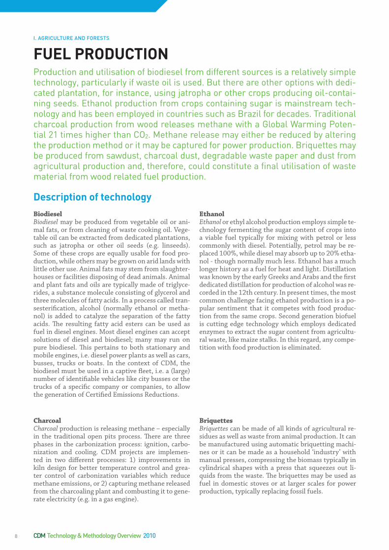
BiodieselBiodiesel may be produced from vegetable oil or ani-mal fats, or from cleaning of waste cooking oil. Vege-table oil can be extracted from dedicated plantations, such as jatropha or other oil seeds (e.g. linseeds). Some of these crops are equally usable for food pro-duction, while others may be grown on arid lands with little other use. Animal fats may stem from slaughter-houses or facilities disposing of dead animals. Animal and plant fats and oils are typically made of triglyce-rides, a substance molecule consisting of glycerol and three molecules of fatty acids. In a process called tran-sesterification, alcohol (normally ethanol or metha-nol) is added to catalyze the separation of the fatty acids. The resulting fatty acid esters can be used as fuel in diesel engines. Most diesel engines can accept solutions of diesel and biodiesel; many may run on pure biodiesel. This pertains to both stationary and mobile engines, i.e. diesel power plants as well as cars, busses, trucks or boats. In the context of CDM, the biodiesel must be used in a captive fleet, i.e. a (large) number of identifiable vehicles like city busses or the trucks of a specific company or companies, to allow the generation of Certified Emissions Reductions.
EthanolEthanol or ethyl alcohol production employs simple te-chnology fermenting the sugar content of crops into a viable fuel typically for mixing with petrol or less commonly with diesel. Potentially, petrol may be re-placed 100%, while diesel may absorb up to 20% etha-nol - though normally much less. Ethanol has a much longer history as a fuel for heat and light. Distillation was known by the early Greeks and Arabs and the first dedicated distillation for production of alcohol was re-corded in the 12th century. In present times, the most common challenge facing ethanol production is a po-pular sentiment that it competes with food produc-tion from the same crops. Second generation biofuel is cutting edge technology which employs dedicated enzymes to extract the sugar content from agricultu-ral waste, like maize stalks. In this regard, any compe-tition with food production is eliminated.
CharcoalCharcoal production is releasing methane – especially in the traditional open pits process. There are three phases in the carbonization process: ignition, carbo-nization and cooling. CDM projects are implemen-ted in two different processes: 1) improvements in kiln design for better temperature control and grea-ter control of carbonization variables which reduce methane emissions, or 2) capturing methane released from the charcoaling plant and combusting it to gene-rate electricity (e.g. in a gas engine).
BriquettesBriquettes can be made of all kinds of agricultural re-sidues as well as waste from animal production. It can be manufactured using automatic briquetting machi-nes or it can be made as a household ‘industry’ with manual presses, compressing the biomass typically in cylindrical shapes with a press that squeezes out li-quids from the waste. The briquettes may be used as fuel in domestic stoves or at larger scales for power production, typically replacing fossil fuels.
FUELPRODUCTIONProduction and utilisation of biodiesel from different sources is a relatively simple technology, particularly if waste oil is used. But there are other options with dedi-cated plantation, for instance, using jatropha or other crops producing oil-contai-ning seeds. Ethanol production from crops containing sugar is mainstream tech-nology and has been employed in countries such as Brazil for decades. Traditional charcoal production from wood releases methane with a Global Warming Poten-tial 21 times higher than CO2. Methane release may either be reduced by altering the production method or it may be captured for power production. Briquettes may be produced from sawdust, charcoal dust, degradable waste paper and dust from agricultural production and, therefore, could constitute a final utilisation of waste material from wood related fuel production.
Descriptionoftechnology
I. AGRICULTURE AND FORESTS
CDM Technology & Methodology Overview 20108
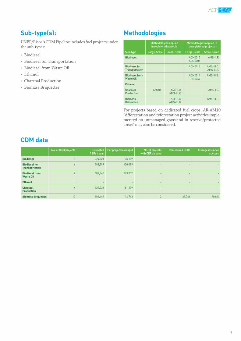
CDMdataNo. of CDM projects Estimated
CERs / yearPer project (average) No. of projects
with CERs issuedTotal issued CERs Average issuance
success
Biodiesel 3 224,321 75,109 - - -
BiodieselforTransportation
6 783,299 130,099 - - -
BiodieselfromWasteOil
2 487,860 243,932 - - -
Ethanol 0 - - - - -
CharcoalProduction
4 322,231 81,139 - - -
BiomassBriquettes 13 181,449 14,743 2 31,766 90,8%
Sub-type(s):UNEP/Risoe’s CDM Pipeline includes fuel projects under the sub-types:
• Biodiesel • Biodiesel for Transportation • Biodiesel from Waste Oil• Ethanol• Charcoal Production• Biomass Briquettes
MethodologiesMethodologies applied in registered projects
Methodologies applied in unregistered projects
Sub-type Large-Scale Small-Scale Large-Scale Small-Scale
Biodiesel ACM0017ACM0006
AMS-II.F.
Biodiesel for Transportation
ACM0017 AMS-III.C.AMS-III.T.
Biodiesel from Waste Oil
ACM0017AM0047
AMS-III.B.
Ethanol
Charcoal Production
AM0041 AMS-I.D.AMS-III.K.
AMS-I.C.
Biomass Briquettes
AMS-I.C.AMS-III.B.
AMS-III.E.
For projects based on dedicated fuel crops, AR-AM10 “Afforestation and reforestation project activities imple-mented on unmanaged grassland in reserve/protected areas” may also be considered.
9

II.WASTEII.1.AGRICULTURALWASTEAgricultural production leaves considerable amounts of agricultural waste. Some of it is recycled into the agricultural production as fertilizer, while large amounts remain unused – and in many instances pose a disposal problem. Uncontrolled burning in the fields is not only a hazardous disposal solution - it is also wasting useful energy. With efficient collection systems, waste from agricultural produc-tion can be utilised as fuel for power and heat production.
In some agricultural industries large amounts of biomass waste is already con-centrated and readily available for utilisation. The palm oil industry, for instance, produces significant amounts of empty fruit bunches that can be incinerated. Li-quid wastes may also be methanized and can secure a basis for own power and process heat production while delivering excess power to the grid. In the sugar industry, significant amounts of bagasse – the waste after extraction of sugar – is an equally excellent fuel. Rice production may also be industrialised to such an extent that rice husks are available in amounts sufficient for incineration in a boiler, thereby securing a basis for power and heat production.
In the forest industry, large concentrations of biomass waste can be utilised for power and heat production, e.g. at sawmills. The forest industry also supplies raw material for briquettes production, where sawdust, charcoal dust, degra-dable waste paper and dust from agricultural production may constitute a final utilisation of waste materials from agriculture related production. The following sectors of agricultural waste utilisation are presented in this section:
• Waste in Forest Industry• Waste in Other Agricultural Industries• Waste in Palm Oil Industries• Waste in Rice Industry• Waste in Sugar Industry
10
“35MWBagasseBasedCogenerationProject”byMumiasSugarCompanyLimited(MSCL)Ref. no. 1404
Mumias Sugar is the leading sugar manufacturer in Ken-ya. It sells sugar through appointed distributors nationwide. The company has diversified into power production. The tech-nology to be employed for the Mumias Cogeneration Project will be based on the conventional steam power cycle involving direct combustion of biomass (bagasse) in a boiler to raise steam, which is then expanded through a condensing extrac-tion turbine to generate electricity. Some of the steam gene-rated will be used in the sugar plant processes and equipment.
Project investment: USD 20,000,000
Project CO2 reduction over a crediting period of 10 years:
1,295,914 tCO2e
Expected CER revenue (CER/USD 10): USD 12,959,140

Forest ResiduesForests are already the prime source of fuel for house-holds where wood collection is a laborious activity and wood fuel is most often used in inefficient cook sto-ves. Alternatively, forest residues, sawmill waste or other sources like, twigs, branches and dry leaves may be used for power and heat production. At the sawmills there are obvious utilisation options for the sawdust, which has little value as fuel in household cook stoves. Many CDM projects are based on the installation of a boiler, for the incineration of the sawdust, producing both power for the sawmill (and possibly also for the power grid) and heat for drying of wood, that often re-places diesel based captive power production.
Other options are normally linked to formal plantations, where pruning is a basic part of efficient plantation ma-nagement, and collection of waste is necessary both in the plantation and at the processing plant. However, for such projects, an important consideration is whether a more formalised utilisation of the waste would compe-te with already existing utilisation in households which would undermine or eliminate the foundation for liveli-hood in the vicinity of the plantation.
Charcoal Charcoal production is releasing methane – especially in the traditional open pits process. CDM project ac-tivities that aim at reducing methane emissions du-ring the carbonization process entail three phases: ig-nition, carbonization and cooling. CDM projects are implemented in two different processes: 1) improve-ment of kiln design for better temperature control and greater control of carbonization variables which reduce methane production, or 2) utilising the relea-sed methane to generate electricity in a gas engine or through a boiler, turbine and generator set.
BriquettesBriquettes can be made from all kinds of forest and agricultural residues as well as waste from animal pro-duction. It can be manufactured using automatic bri-quetting machines or it can be made as a household ‘industry’ with manual presses, compressing the bio-mass typically in cylindrical shapes with a press that squeezes out liquids from the waste. The briquettes may be used as fuel in domestic stoves or at larger scales for power production, typically replacing fossil fuels.
Sub-type(s):UNEP/Risoe’s CDM Pipeline includes forest industry projects under four different sub-types:
• Forest Residues: Sawmill Waste• Forest Residues: Other• Charcoal Production• Biomass Briquettes
WASTEINTHEFORESTINDUSTRYIn developing countries, biomass - and particularly wood - accounts for approxi-mately 38% of the primary energy use among more than two billion consumers, many of whom have no access to modern energy services. In the forest industry, large concentrations of biomass waste can be utilised for power and heat produc-tion and, thus, provide access to modern energy services. The forest industry is also the foundation for traditional charcoal production. During this process, large amounts of methane with a Global Warming Potential 21 times higher than CO2 are released. This may be reduced, or entirely avoided, by altering the production me-thod or it may be captured for power production. The forest industry also supplies raw material for briquettes production, where sawdust, charcoal dust, degradable waste paper and dust from agricultural production could constitute a final utilisa-tion of waste materials from wood related production.
Descriptionoftechnology
II. WASTEII.1. AGRICULTURAL WASTE
11
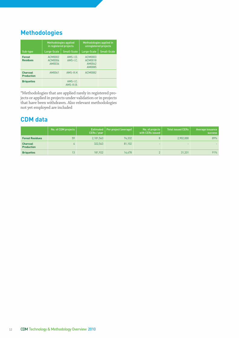
MethodologiesMethodologies applied in registered projects
Methodologies applied in unregistered projects
Sub-type Large-Scale Small-Scale Large-Scale Small-Scale
ForestResidues
ACM0002 ACM0006
AM0036
AMS-I.D. AMS-I.C.
ACM0003ACM0018
AM0042AM0085
CharcoalProduction
AM0041 AMS-III.K ACM0082
Briquettes AMS-I.C. AMS-III.B.
*Methodologies that are applied rarely in registered pro-jects or applied in projects under validation or in projects that have been withdrawn. Also relevant methodologies not yet employed are included
CDMdataNo. of CDM projects Estimated
CERs / yearPer project (average) No. of projects
with CERs issuedTotal issued CERs Average issuance
success
ForestResidues 59 2,181,543 74,332 8 2,902,000 89%
CharcoalProduction
4 322,543 81,102 - - -
Briquettes 13 181,922 14,478 2 31,331 91%
CDM Technology & Methodology Overview 201012

DescriptionoftechnologyAgricultural ResiduesBiomass primarily refers to agricultural residues, which are converted into electricity and steam through direct combustion - usually of solids. Such generation involves the construction of a boiler, a steam turbine and a gene-rator and auxiliary facilities such as a water deminerali-sation plant, a cooling tower, air pollution control devi-ces and a storage yard. In some cases the cooling tower may be replaced by a heat exchanger, allowing the uti-lisation of waste heat when there is a demand for low temperature process heating (e.g. for drying) or cooling in the area where the power plant is located. Very often such power production replaces captive diesel power generation at the plant, thus, reducing greenhouse gas emissions.
Many crops leave considerable amounts of waste, e.g. maize, sorghum, millet, wheat, nut and cotton produc-tion. In Rajasthan, India, waste from mustard produc-tion is the basis for several CDM projects. Some crops leave just as much waste as they do usable crop and with little alternative uses; the resources for the assessment of biomass residue is often lagging behind. Biomass energy projects can be built in a wide range of sizes and for a wide range of applications. Projects can be as lar-ge as 100 MW power stations generating both electricity and heat, but are typically 15-30 MW in size, either de-dicated to a single crop residue or a combination of seve-ral sources. Biomass energy projects are also technically feasible in much smaller sizes, but are rarely commercia-lly viable below 8-10 MW, depending on availability and pricing of biomass residues.
Sub-type(s):UNEP/Risoe’s CDM Pipeline includes other agricul-tural residues projects under two different sub-types:
• Agricultural Residues: Mustard Crop • Agricultural Residues: Other Kinds
MethodologiesMethodologies applied in registered projects
Methodologies applied in unregistered projects
Sub-type Large-Scale Small-Scale Large-Scale Small-Scale
AgriculturalResidues:MustardCrop
AMS-I.D. AMS-I.C.
AgriculturalResidues:OtherKinds
ACM0002ACM0003ACM0006
AMS-I.D. AMS-I.C.
AMS-III.E.
ACM0018AM0036
AMS-III.Z.
CDMdataNo. of CDM projects Estimated
CERs / yearPer project (average) No. of projects
with CERs issuedTotal issued CERs Average issuance
success
AgriculturalResidues:MustardCrop
10 320,521 32,188 1 145,820 100%
AgriculturalResidues:OtherKinds
197 16,739,000 86,821 86 3,228,192 90%
WASTEINOTHERAGRICULTURALINDUSTRIESBiomass accounts for approximately 15% of global primary energy use and 38% of the primary energy use in developing countries. More than 80% of biomass energy is used by more than two billion consumers, many of whom have no access to mo-dern energy services. However, in some agricultural industries, large concentra-tions of biomass waste can be utilised for power and heat production, thereby pro-viding access to modern energy services.
II. WASTEII.1. AGRICULTURAL WASTE
13

The palm oil industry produces large amounts of solid waste from empty fruit bunches (EFB), kernels and fi-bres, as well as liquid waste, normally referred to as POME (Palm Oil Mill Effluent) - a liquid waste with a high content of Chemical Oxygen Demand (COD). If not utilised, the waste creates a disposal problem. However, the waste may be turned into a valuable fuel through in-cineration in a boiler, allowing the production of process heat and power for the oil production (captive power and heat production). Alternatively, by composting POME, methane emissions may be avoided.
Incineration of Solid WasteUsing the palm oil solid waste – EFB, crushed kernels and fibres – for electricity and steam generation involves the construction of a boiler, a steam turbine and a generator and auxiliary facilities such as a water demineralisation plant, a cooling tower, air pollution control devices and EFB storage yard. In some cases the cooling tower may be replaced by a heat exchanger, allowing the utilisation of waste heat when there is a demand for low temperatu-re process heating (e.g. for drying) or cooling in the area where the palm oil mill is located. Very often such power production replaces captive diesel power generation at the plant, thereby reducing greenhouse gas emissions.
Composting of POMEIn order to avoid methane production from the liquid palm oil waste (POME) high concentrations of oxygen are needed to create aerobic conditions. The most com-mon way of treating POME is to store it in open lago-ons (ponds), where the waste sinks to the bottom and releases methane into the air. The water will gradually be released into a river, to keep a constant level in the pond. Composting POME is rather simple: the emp-ty fruit bunches are collected and added to the liquid POME, along with plenty of air, which initiates the com-posting process. The composting process is completed in 10-12 weeks, depending on temperature, oxygen le-vel, etc., at which time the compost can be used as ferti-
lizer at the palm plantation. The composting eliminates, or reduces significantly, the methane production and the greenhouse effect of palm oil production simply by ex-changing methane, which has a Global Warming Poten-tial (GWP) of 21, with CO2 which has a GWP of 1.
Sub-type(s):UNEP/Risoe’s CDM Pipeline includes palm oil indus-try projects under two different sub-types:
• Palm Oil Solid Waste • Palm Oil Waste
WASTEINPALMOILINDUSTRYBiomass accounts for approximately 15% of global primary energy use and 38% of the primary energy use in developing countries. More than 80% of biomass ener-gy is used by more than two billion consumers, many of whom have no access to modern energy services. However, in some agricultural industries, large concen-trations of biomass waste can be utilised for power and heat production, thereby providing access to modern energy services. The palm oil industry produces sig-nificant amounts of empty fruit bunches that can be incinerated, as well as liquid wastes that may be methanized and secure a basis for own power and process heat production while delivering excess power to the grid.
Descriptionoftechnology
II. WASTEII.1. AGRICULTURAL WASTE
CDM Technology & Methodology Overview 201014

MethodologiesMethodologies applied in registered projects
Methodologies applied in unregistered projects
Sub-type Large-Scale Small-Scale Large-Scale Small-Scale
PalmOilSolidWaste
ACM0002ACM0006
AM0036AM0039
AMS-I.C.AMS-I.D
AMS-III.E.AMS-III.G.
AM0057 AMS-III.H.AMS-III.F.AMS-I.A.
PalmOilWaste(compostingofPOME)
AM0025 AMS-I.C.AMS-I.D.
AMS-III.H.
CDMdataNo. of CDM projects Estimated
CERs / yearPer project (average) No. of projects
with CERs issuedTotal issued CERs Average issuance
success
PalmOilSolidWaste
48 3,279,802 68,421 24 457,192 61%
PalmOilWaste(compostingofPOME)
8 276,412 34,124 - - -
15

Biomass primarily refers to agricultural residues that are converted into electricity and steam through direct com-bustion - usually of solids. Such generation involves the construction of a boiler, a steam turbine and a generator and auxiliary facilities such as a water demineralisation plant, a cooling tower, air pollution control devices and a storage yard. In some cases the cooling tower may be replaced by a heat exchanger, allowing the utilisation of waste heat when there is a demand for low temperatu-re process heating (e.g. for drying) or cooling in the area where the power plant is located. Very often such power production replaces captive diesel power generation at the plant thereby reducing greenhouse gas emissions.
Incineration of Rice HuskThe production of rice leaves rice husks as a waste mate-rial, which may be utilised as fuel in a boiler if quantities are sufficient. It takes five tons of rice paddy to produ-ce one ton of rice husk waste, and it takes approxima-tely 100,000 tons of rice husk per year to fuel a 10 MW power plant. Normal yield for rice is 3-4 tons per hectare (although the yield in China is almost double that), thus, requiring approximately 150,000 hectares (1500 square kilometres) to fuel a power plant.
Biomass energy projects can be built in a wide range of sizes and for a wide range of applications. Projects can be as large as 100 MW power stations generating both electricity and heat, but are typically 15-30 MW in size. Biomass energy projects are also technically feasible in much smaller sizes, but are rarely commercially viable below 8-10 MW, depending on availability and pricing of biomass residues.
Clinker Replacement in CementAsh from incineration of rice husk may further be used as pozzolana for cement production, where it reduces the need for clinker. This creates more options for gre-enhouse gas emissions reduction that may be explored if cement production facilities exist within a reasonable distance from a rice husk incineration plant. For more on the cement industry, see ‘other industrial processes’.
Sub-type(s):UNEP/Risoe’s CDM Pipeline includes agricultural re-sidues, rice husk projects specifically under the sub-type:
• Agricultural Residues: Rice Husk
MethodologiesMethodologies applied in registered projects
Methodologies applied in unregistered projects
Sub-type Large-Scale Small-Scale Large-Scale Small-Scale
AgriculturalResidues:RiceHusk
ACM0002ACM0003ACM0006AM0004
AMS-I.A.AMS-I.C.AMS-I.D.AMS-III.E.AMS-III.G.
ACM0018AM0036
CDMdataNo. of CDM projects Estimated
CERs / yearPer project (average) No. of projects
with CERs issuedTotal issued CERs Average issuance
success
AgriculturalResidues:RiceHusk
160 8,739,190 56,112 29 2,530,801 95%
WASTEINTHERICEINDUSTRYBiomass accounts for approximately 15% of global primary energy use and 38% of the primary energy use in developing countries. More than 80% of biomass ener-gy is used by more than two billion consumers, many of whom have no access to modern energy services. However, in some agricultural industries, large concen-trations of biomass waste can be utilised for power and heat production, thereby providing access to modern energy services. In some places rice production is in-dustrialised to such an extent that rice husks are available in amounts sufficient for incineration in a boiler, thus, securing a basis for power and heat production.
Descriptionoftechnology
II. WASTEII.1. AGRICULTURAL WASTE
CDM Technology & Methodology Overview 201016
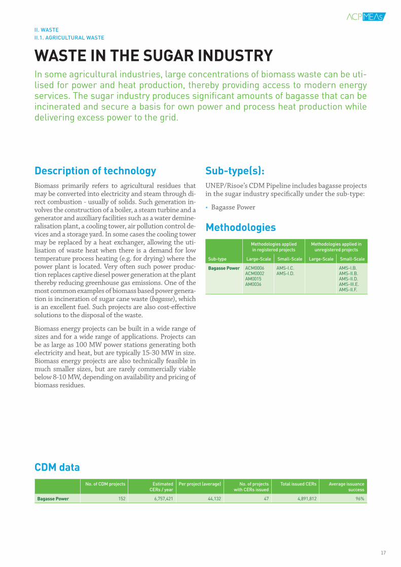
DescriptionoftechnologyBiomass primarily refers to agricultural residues that may be converted into electricity and steam through di-rect combustion - usually of solids. Such generation in-volves the construction of a boiler, a steam turbine and a generator and auxiliary facilities such as a water demine-ralisation plant, a cooling tower, air pollution control de-vices and a storage yard. In some cases the cooling tower may be replaced by a heat exchanger, allowing the uti-lisation of waste heat when there is a demand for low temperature process heating (e.g. for drying) where the power plant is located. Very often such power produc-tion replaces captive diesel power generation at the plant thereby reducing greenhouse gas emissions. One of the most common examples of biomass based power genera-tion is incineration of sugar cane waste (bagasse), which is an excellent fuel. Such projects are also cost-effective solutions to the disposal of the waste.
Biomass energy projects can be built in a wide range of sizes and for a wide range of applications. Projects can be as large as 100 MW power stations generating both electricity and heat, but are typically 15-30 MW in size. Biomass energy projects are also technically feasible in much smaller sizes, but are rarely commercially viable below 8-10 MW, depending on availability and pricing of biomass residues.
Sub-type(s):UNEP/Risoe’s CDM Pipeline includes bagasse projects in the sugar industry specifically under the sub-type:
• Bagasse Power
MethodologiesMethodologies applied in registered projects
Methodologies applied in unregistered projects
Sub-type Large-Scale Small-Scale Large-Scale Small-Scale
BagassePower ACM0006ACM0002AM0015AM0036
AMS-I.C.AMS-I.D.
AMS-I.B.AMS-II.B.AMS-II.D.AMS-III.E.AMS-II.F.
CDMdataNo. of CDM projects Estimated
CERs / yearPer project (average) No. of projects
with CERs issuedTotal issued CERs Average issuance
success
BagassePower 152 6,757,421 44,132 47 4,891,812 96%
WASTEINTHESUGARINDUSTRYIn some agricultural industries, large concentrations of biomass waste can be uti-lised for power and heat production, thereby providing access to modern energy services. The sugar industry produces significant amounts of bagasse that can be incinerated and secure a basis for own power and process heat production while delivering excess power to the grid.
II. WASTEII.1. AGRICULTURAL WASTE
17
II.2.LIQUIDWASTEThere are liquid wastes in several sectors of the economy. Agriculture is an im-portant source, where manure particularly poses an environmental burden, but where methane may be captured and used for energy production before the ma-nure is used as fertilizer.
Wastewater treated in wastewater treatment plants can be an additional source of methane release into the atmosphere, where capture and destruction or utilisa-tion is an obvious possibility for reducing greenhouse gas emissions. Otherwise, it may be aerated to avoid anaerobic conditions and the uncontrolled release of methane.
Additionally, the food industry produces significant amounts of waste oil that is easily transformed into useful fuel.
The following are recorded as sources of liquid waste:
• Manure• Waste Oil• Wastewater
CerveceríaHondureñaMethaneCaptureProjectRef. no. 896
The Cervecería Hondureña Methane Capture Project consists of the installation of a biodigester for treatment of wastewater from the production of beer and sodas. The wastewater con-tains yeast and other waste that must be eliminated before the effluents reach the rivers. The small-scale project activity reduces emissions in two stages: by avoiding the emissions of methane into the atmosphere, and by the substitution of ther-mal energy that would have been produced otherwise with the use of the highly contaminating Bunker C (residual fuel oil). In the absence of the project, the methane from the decomposi-tion of wastewater from the beer factory would have found its way into the atmosphere.
Project investment: USD 1,400,000
Project CO2 reduction over a crediting period of 7 years:
51,116 tCO2e
Expected CER revenue (CER/USD 10): USD 511,160
18

DescriptionoftechnologyManureManure, particularly from pigs, is not only a valuable fer-tilizer, but also a potential source of energy production. Pig farming is widespread in many developing countries, either in larger farms or as household pigsties. At lar-ger farms, manure is typically kept in large ponds. The-se are replaced by a bio digester, which is essentially an enclosed tank where the waste is stored under anaerobic conditions, hence producing biogas. The gas is typically used as fuel in a gas engine, though it may also be used as fuel in a boiler for generation of heat and/or power if the methane generation is sufficient to make this a via-ble solution. The biogas can also be distributed directly to households and industrial facilities through gas pipe-lines. While pigs are the most dominant source of manu-re, poultry litter from industrial poultry farms – or from households if efficient collection systems can be establis-hed – is also a potential source for methane generation.
Domestic ManureSome bio digesters are made very easily by digging a hole in the ground, which is then covered with plastic inside and on top, with a small piping outlet where the biogas can be released. This is typically used for treatment of domestic manure from households and small farms. Lar-ger farms and industrial facilities produce greater volu-mes of waste and, therefore, require larger storage capa-city. Consequently, they will need to construct a storage tank to dispose the waste. These types of CDM projects can be implemented in practically all developing coun-tries where farming takes place. They are particularly suited to countries with low development since a sim-ple bio digester is easily built, has minimal maintenance, and significantly increases energy access - especially for rural households. Therefore, there is great potential for programmatic CDM in this sector. More advanced bio-gas systems are equally suited for developing countries since the technology is widely available, well known and has been used successfully for several decades.
Sub-type(s):UNEP/Risoe’s CDM Pipeline includes manure-based projects under the sub-types:
• Manure • Domestic Manure• Agricultural Residues: Poultry Litter
MethodologiesMethodologies applied in registered projects
Methodologies applied in unregistered projects
Sub-type Large-Scale Small-Scale Large-Scale Small-Scale
Manure ACM0010AM0006AM0016
AMS-I.A.AMS-I.D.AMS-I.C.AMS-III.D.
ACM0006AM0073
AMS-II.C.AMS-III.H.AMS-III.Q. AMS-III.R.
DomesticManure
AMS-I.C.AMS-I.E.AMS-III.R.
AgriculturalResidues:PoultryLitter
AMS-I.D.AMS-III.DAMS-III.E.
ACM0002ACM0006AM0025
MANUREManure from livestock in the agricultural sector in developing countries is typically sprayed on fields as fertilizer, while excess manure is stored in open ponds, which generates methane - a potent greenhouse gas. The damaging release of methane and carbon dioxide into the environment can be avoided by capturing and utilising the methane for energy purposes.
CDMdataNo. of CDM projects Estimated
CERs / yearPer project (average) No. of projects
with CERs issuedTotal issued CERs Average issuance
success
Manure 263 11,358,391 43,291 51 5,223,211 48%
DomesticManure 17 734,312 43,821 11,761 1,761 60%
AgriculturalResidues:PoultryLitter
5 378,982 76,213 - - -
II. WASTEII.2. LIQUID WASTE
19
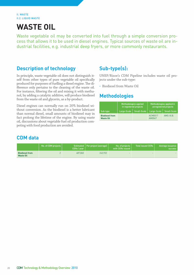
DescriptionoftechnologyIn principle, waste vegetable oil does not distinguish it-self from other types of pure vegetable oil specifically produced for purposes of fuelling a diesel engine. The di-fference only pertains to the cleaning of the waste oil. For instance, filtering the oil and mixing it with metha-nol, by adding a catalytic additive, will produce biodiesel from the waste oil and glycerin, as a by-product.
Diesel engines can normally run on 20% biodiesel wi-thout conversion. As the biodiesel is a better lubricant than normal diesel, small amounts of biodiesel may in fact prolong the lifetime of the engine. By using waste oil, discussions about vegetable fuel oil production com-peting with food production are avoided.
Sub-type(s):UNEP/Risoe’s CDM Pipeline includes waste oil pro-jects under the sub-type:
• Biodiesel from Waste Oil
MethodologiesMethodologies applied in registered projects
Methodologies applied in unregistered projects
Sub-type Large-Scale Small-Scale Large-Scale Small-Scale
BiodieselfromWasteOil
ACM0017AM0047
AMS-III.B.
CDMdataNo. of CDM projects Estimated
CERs / yearPer project (average) No. of projects
with CERs issuedTotal issued CERs Average issuance
success
BiodieselfromWasteOil
2 487,860 243,932 - - -
WASTEOILWaste vegetable oil may be converted into fuel through a simple conversion pro-cess that allows it to be used in diesel engines. Typical sources of waste oil are in-dustrial facilities, e.g. industrial deep fryers, or more commonly restaurants.
II. WASTEII.2. LIQUID WASTE
CDM Technology & Methodology Overview 201020

Anaerobic Treatment of WastewaterWastewater is an important source of methane emis-sions and, consequently, a source of potentially signifi-cant greenhouse gas emissions reduction - as methane has a Global Warming Potential (GWP) of 21 compa-red to CO2 with a GWP of only 1. Methane emissions stem from the anaerobic treatment of wastewater with a high content of Chemical Oxygen Demand (COD). The most common way of treating wastewater and sludge is to store it in open lagoons (ponds), where the waste sinks to the bottom and releases methane into the air. The water will gradually be released into a river to keep a constant level in the pond. Alternatively, controlled anaerobic conditions can be established by creating an enclosed and anaerobic environment and optimising the process in which bacteria convert organic matter into biogas. Such systems are normally stationary, but sma-ller systems may also be modular and container-based. Mixing the wastewater and sludge with other biologi-cal solid matter (e.g. straw) may even increase the bio-gas production (though this might not yet be supported by existing CDM methodologies). Capturing the biogas, cleaning it and stripping it of hydrogen sulphide facilita-tes energy production in gas engines and/or in heaters that may replace conventional sources of energy supply, e.g. in industrial facilities. Otherwise, it may be flared, thereby converting methane into CO2 and H2. Such pro-jects are seen in a number of differing industries such as slaughterhouses, pulp and paper production, starch production and palm oil production, to mention a few. Projects may also be implemented at public wastewater treatment plants.
Aerobic Treatment of WastewaterAnother strategy is to avoid methane production altoge-ther. This requires high concentration of oxygen to ensu-re aerobic treatment of wastewater. Here, aerobic microor-ganisms consume dissolved oxygen as they decompose the organic carbon and nitrogenous compounds. By en-gineering the biochemical oxidation of wastewater, oxy-gen is supplied to the aerobic microorganisms so that they will consume the organic carbon. The result is the conversion of organic pollutants into inorganic com-pounds and new microbial cells – and importantly the avoidance of methane emissions which can be credited under CDM.
Sub-type(s):UNEP/Risoe’s CDM Pipeline includes wastewater pro-jects under the sub-types:
• Wastewater• Aerobic Treatment of Wastewater
MethodologiesMethodologies applied in registered projects
Methodologies applied in unregistered projects
Sub-type Large-Scale Small-Scale Large-Scale Small-Scale
Wastewater AM0013AM0022
AMS-I.A.AMS-I.C.AMS-I.D.AMS-III.H.AMS-III.O.
ACM0014AM0025
AMS-III.F.AMS-III.Y.
AerobicTreatmentofWastewater
AMS-III.I.
CDMdataNo. of CDM projects Estimated
CERs / yearPer project (average) No. of projects
with CERs issuedTotal issued CERs Average issuance
success
Waste water 253 12,511,840 50,234 11 1,397,234 109%
Aerobic Treatment of Waste water
1 55,553 55,553 1 43,033 75%
WASTEWATERIndustrial organic wastewater comes from various industries such as pulp and pa-per production, agriculture, distillery, etc. Municipal wastewater produces sludge, which can either be used as a source of methane generation for energy production in a biogas digester, or be aerated to avoid anaerobic conditions and the uncontro-lled release of methane.
Descriptionoftechnology
II. WASTEII.2 LIQUID WASTE
21

II.3SOLIDWASTEMunicipal solid waste is an important source for potential energy production. The inorganic fraction contains large amounts of combustible waste, depending on current recycling. The organic fraction is the source of methane and other emis-sions from the landfills, causing odour and risk of explosion. Collecting it has the potential to generate large amounts of Certified Emission Reductions either by utilising the methane for energy production or eliminating it through flaring. Otherwise, it may be eliminated altogether through composting.
Organic matter may also be gasified for the development of methane, which is combustible in gas engines or directly usable for cooking in households. In such cases, it typically replaces conventional sources of energy.
Technologies used in CDM projects concerning solid waste are presented under the following headings:
• Composting • Gasification Options• Incineration Options• Landfills
CompostingofsolidbiomasswasteseparatedfromthePalmOilMillEffluentthroughtheuseofAVCSludgeDewateringSystemRef. no. 2357
The wastewater from the palm oil mill is treated through the conventional ponding system including cooling, anaero-bic, facultative and settling ponds, followed by final discharge pond. With regular dislodging of the pond system and suffi-cient retention period, the treated water complies with the host country’s environmental requirements. The CDM project activity will replace the existing anaerobic ponds with a co-composting of the POME and a smaller portion of the solid biomass waste from the palm oil mill. In order to obtain a bet-ter management of the water balance in the composting pro-cess, a mechanical separation of the POME, the AVC Sludge Dewatering System, is introduced. The POME will be separa-ted into a water fraction and a sludge fraction with the sludge containing more than 80% of the organic material. The sludge fraction will be transferred to a compost site at the palm oil mill where it will be treated aerobically together with a sma-ller amount of solid biomass waste. The compost will be used as fertilizer at nearby palm plantations.
Project investment: USD 1,010,000
Project CO2 reduction over a crediting period of 10 years:
184,323 tCO2e
Expected CER revenue (CER/USD 10): USD 1,843,230
22

CompostingComposting can be used to avoid the production of me-thane by changing how organic waste is stored and de-composed, from anaerobic to aerobic conditions. Com-posting is essentially a technology where different kinds of waste and other materials are combined under aero-bic conditions, whereby the waste gradually decompo-ses. In some cases the waste can be recycled or used in other parts of an industrial production line. Most com-monly, however, it is used as fertilizer in agricultural production. The key to successful composting is the co-rrect combination of dry and wet waste combined with plenty of air to avoid the anaerobic stage where methane is produced.
Municipal Waste - LandfillsThe most basic form of composting, well known to most people, is simply an open bin where organic household waste is combined with worms and soil, which gradually turns into humus. On a larger scale, waste is shredded and piles are established that need to be turned regu-larly with simple equipment to avoid heat generation and methane emissions. Composting is most efficient if the waste is free from inorganic fractions and remo-val of inorganic material can improve the process. Opti-mised treatment of municipal waste requires separation of usable raw materials such as metals and glass, com-posting of organic fractions and incineration of inorga-nic matter.
Composting is commonly used in the agricultural sector where agricultural waste – both plant material and, to a limited extent, animal material - are being composted, thereby creating humus, which can be used as fertilizer.
Palm Oil Mill Effluent (POME)A common example of methane production avoidance is in the production of palm oil, which results in four types of biomass waste: empty fruit bunches, fibres, palm ker-nel shells and Palm Oil Mill Effluent (POME) - a liquid waste with a high content of Chemical Oxygen Demand (COD). In order to avoid methane production, high con-centrations of oxygen are needed to create aerobic con-ditions. The most common way of treating POME has been to store it in open lagoons (ponds), where the was-te sinks to the bottom and releases methane into the air. The water will gradually be released into a river, to keep a constant level in the pond. Composting POME is rather simple: the empty fruit bunches are collected and added together with the liquid POME, along with plenty of air, which initiates the composting process. The compost is ready in 10-12 weeks, depending on temperature, oxy-gen level, etc.
Sub-type(s):UNEP/Risoe’s CDM Pipeline includes composting projects under the sub-types:
• Composting • Landfill Composting • Palm Oil Waste• Industrial Solid Waste
COMPOSTINGMunicipal solid waste contains large fractions of organic waste, particularly in de-veloping countries where reuse of inorganic fractions is widespread. The organic fraction of the waste is the source of methane and other emissions from the land-fills, causing odour and risk of explosion. Methane is a highly polluting Greenhouse Gas (GHG), with a global warming potential 21 times that of carbon dioxide. There-fore, it has the potential to generate large amounts of Certified Emission Reduc-tions if the methane emissions can be eliminated e.g. through composting. In the process other sources of waste may be included, such as sludge from wastewater treatment or waste from the food industry. The palm oil industry has established a number of composting projects under the Clean Development Mechanism. Com-posting is also appropriate for liquid wastes and manure.
Descriptionoftechnology
II. WASTEII.3. SOLID WASTE
23
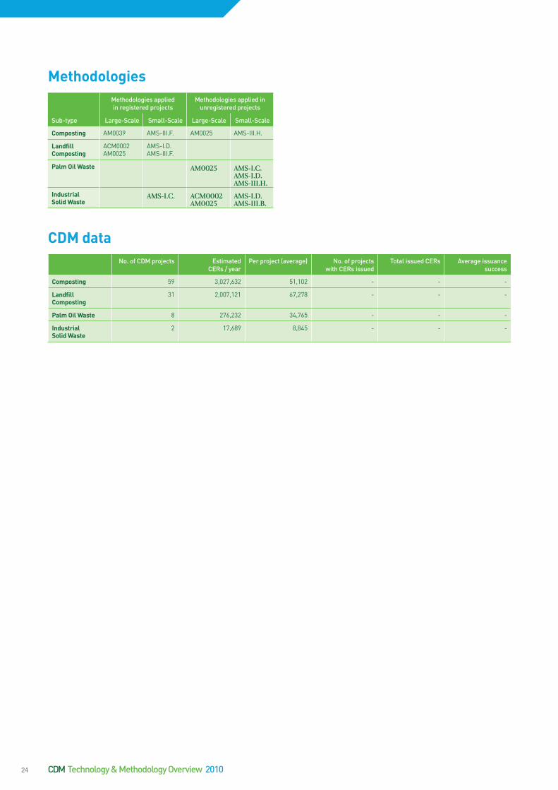
CDMdataNo. of CDM projects Estimated
CERs / yearPer project (average) No. of projects
with CERs issuedTotal issued CERs Average issuance
success
Composting 59 3,027,632 51,102 - - -
LandfillComposting
31 2,007,121 67,278 - - -
PalmOilWaste 8 276,232 34,765 - - -
IndustrialSolidWaste
2 17,689 8,845 - - -
MethodologiesMethodologies applied in registered projects
Methodologies applied in unregistered projects
Sub-type Large-Scale Small-Scale Large-Scale Small-Scale
Composting AM0039 AMS-III.F. AM0025 AMS-III.H.
LandfillComposting
ACM0002AM0025
AMS-I.D.AMS-III.F.
PalmOilWaste AM0025 AMS-I.C.AMS-I.D.AMS-III.H.
IndustrialSolidWaste
AMS-I.C. ACM0002AM0025
AMS-I.D.AMS-III.B.
CDM Technology & Methodology Overview 201024

Gasification is one way to utilise the energy content in solid waste. Other options are waste incineration and landfill gas exploitation, although gasification is speci-fically designed to maximise gas development, compa-red to landfill gas installations, which are utilising the methane that develops unavoidably from the anaero-bic conditions in a landfill. It differs from incineration in the sense that it requires less additional energy input for operation. Gasification is different from composting, which has the exact opposite purpose, namely to avoid gas (methane) development altogether by changing anaerobic conditions to aerobic ones.
Gasification of BiomassGasification of biomass is generally defined as the ther-mochemical conversion of a solid or liquid carbon-based material (feedstock) into a combustible gaseous product (combustible gas) by the supply of a gasification agent. The thermochemical conversion changes the chemical structure of the biomass by means of high temperatu-re. Steam is the most commonly used indirect gasifica-tion agent, because it is easily produced and increases the hydrogen content of the combustible gas. The main product is a syngas, which contains carbon monoxide, hydrogen and methane, and is developed at tempera-tures in excess of 800°C. The process is largely exother-mic, but some heat may be required to initialise and sus-tain the gasification process. Gasification plants recover the thermal energy contained in the garbage in highly efficient boilers that generate steam which can either be sold directly to industrial customers or used on-site to drive turbines for electricity production.
Pre-processing of the municipal solid waste is necessary, and the degree of pre-processing to convert the waste into a suitable feed material is a major criterion. Unsor-ted MSW is not suitable for most thermal technologies because of its varying composition and size of some of its constituent materials. The main steps involved in pre-processing of MSW include manual and mechanical se-paration or sorting, shredding, grinding, blending with other materials, drying and pelletization. The purpose of pre-processing is to produce a feed material with consis-tent physical characteristics and chemical properties.
Sub-type(s):UNEP/Risoe’s CDM Pipeline includes gasification projects under two different sub-types:
• Gasification of Biomass • Switch from Fossil Fuel to Piped Biogas
MethodologiesMethodologies applied in registered projects
Methodologies applied in unregistered projects
Sub-type Large-Scale Small-Scale Large-Scale Small-Scale
GasificationofBiomass
AMS-I.A.AMS-I.DAMS-III.I.
AM0025AM0039AM0069
AMS-I.B.AMS-I.C.AMS-III.F.AMS-III.H.
SwitchfromFossilFueltoPipedBiogas
AMS-I.C.
CDMdataNo. of CDM projects Estimated
CERs / yearPer project (average) No. of projects
with CERs issuedTotal issued CERs Average issuance
success
GasificationofBiomass
14 282,244 20,289 - - -
SwitchfromFossilFueltoPipedBiogas
2 43,378 21,689 - - -
GASIFICATIONOPTIONSOrganic matter may be gasified for the development of methane, which is a gas combustible in gas engines or directly usable for cooking in households. When doing so it normally replaces conventional sources of energy. If the organic matter originally is being kept under anaerobic conditions, controlled gasification will fur-ther help to eliminate uncontrolled emissions of methane, which is a greenhouse gas with a global warming potential 21 times that of CO2. Eliminating such emis-sions and producing power from controlled gasification has the potential to gene-rate large amounts of Certified Emission Reductions. Other gasification options (manure) are under Liquid Waste.
Descriptionoftechnology
II. WASTEII.3. SOLID WASTE
25
DescriptionoftechnologyAgricultural ResiduesBiomass primarily refers to agricultural residues, which are converted into energy through direct combustion, usually of solids, in boilers or furnaces – or less com-monly gasification via a physical, chemical or biological conversion process. A biomass energy project can be de-signed to cogenerate both heat and electricity, increa-sing its overall energy efficiency and financial viability. The most common examples are sugar cane waste (ba-gasse), short rotation crops such as straw and husks, energy crops, corn and trees grown in short-rotation plantations. Such projects may also create a cost-effec-tive solution to the disposal of agricultural or industrial wastes.
Biomass energy projects can be built in a wide range of sizes and for a wide range of applications. Projects can be as large as 100 MW power stations generating both electricity and heat. Biomass energy projects can also be much smaller, but are rarely commercially viable below 8-10 MW, depending on availability and pricing of bio-mass residues.
In addition to potential greenhouse abatement benefits, biomass energy projects can address many other envi-ronmental issues such as decreasing soil erosion, contro-lling nitrogen runoff, and protecting watersheds.
Bagasse, Palm Oil and Forestry WasteThere is a great potential for biomass CDM projects ba-sed on bagasse, palm oil solid waste and a range of other crops such as, maize, sorghum, millet, wheat, nut and cotton production that produce significant amounts of waste with little use, and are often burned or left to rot in the fields. Additionally, products, by-products, resi-dues and waste from forestry related industries are com-mon fuel sources for biomass incineration projects..
Sub-type(s):UNEP/Risoe’s CDM Pipeline includes solid waste inci-neration projects under the sub-types:
• Agricultural Residues: Other Kinds• Agricultural Residues: Mustard Crop• Agricultural Residues: Rice Husk• Palm Oil Solid Waste • Bagasse Power • Forest Residues: Sawmill Waste• Forest Residues: Other
INCINERATIONOPTIONSBiomass accounts for approximately 15% of global primary energy use and 38% of the primary energy use in developing countries. More than 80% of biomass ener-gy is used at low efficiencies for cooking, heating and lighting by more than two bi-llion consumers, many of whom rely on traditional biomass fuels and/or have no access to modern energy services. Dependence on traditional biomass is far grea-ter in sub-Saharan Africa than any other region of the world.
II. WASTEII.3. SOLID WASTE
CDM Technology & Methodology Overview 201026
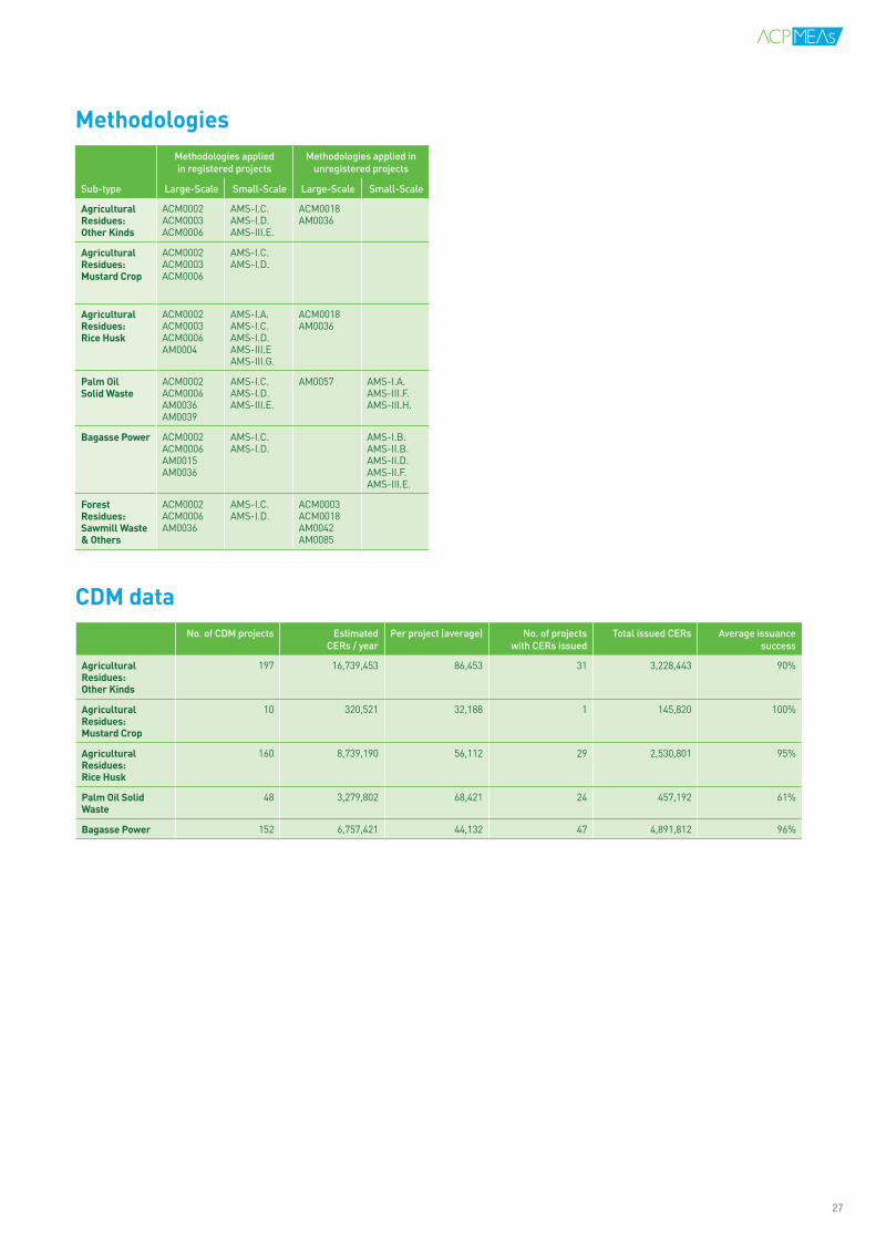
CDMdataNo. of CDM projects Estimated
CERs / yearPer project (average) No. of projects
with CERs issuedTotal issued CERs Average issuance
success
AgriculturalResidues:OtherKinds
197 16,739,453 86,453 31 3,228,443 90%
AgriculturalResidues:MustardCrop
10 320,521 32,188 1 145,820 100%
AgriculturalResidues:RiceHusk
160 8,739,190 56,112 29 2,530,801 95%
PalmOilSolidWaste
48 3,279,802 68,421 24 457,192 61%
BagassePower 152 6,757,421 44,132 47 4,891,812 96%
MethodologiesMethodologies applied in registered projects
Methodologies applied in unregistered projects
Sub-type Large-Scale Small-Scale Large-Scale Small-Scale
AgriculturalResidues:OtherKinds
ACM0002ACM0003ACM0006
AMS-I.C.AMS-I.D.AMS-III.E.
ACM0018AM0036
AgriculturalResidues:MustardCrop
ACM0002ACM0003ACM0006
AMS-I.C.AMS-I.D.
AgriculturalResidues:RiceHusk
ACM0002ACM0003ACM0006AM0004
AMS-I.A.AMS-I.C.AMS-I.D.AMS-III.EAMS-III.G.
ACM0018AM0036
PalmOilSolidWaste
ACM0002ACM0006AM0036AM0039
AMS-I.C.AMS-I.D.AMS-III.E.
AM0057 AMS-I.A.AMS-III.F.AMS-III.H.
BagassePower ACM0002ACM0006AM0015AM0036
AMS-I.C.AMS-I.D.
AMS-I.B.AMS-II.B.AMS-II.D.AMS-II.F.AMS-III.E.
ForestResidues:SawmillWaste&Others
ACM0002ACM0006AM0036
AMS-I.C.AMS-I.D.
ACM0003ACM0018AM0042AM0085
27

DescriptionoftechnologyLandfillsWaste that is left at an unmanaged landfill produces highly polluting Landfill Gasses (LFG), the most com-mon being methane gas and carbon dioxide. Further-more, unmanaged landfills result in poor air quality, odour, and increase the risk of disease and infection to neighbouring people. It is estimated that Municipal So-lid Waste Management contributes to 13% of global me-thane emissions.
Methane is produced through natural processes of bac-terial decomposition of organic waste under anaerobic conditions. Methane is a potent greenhouse gas with a Global Warming Potential (GWP) 21 times that of car-bon dioxide. Therefore, it has the potential of generating a large amount of carbon credits.
Landfill gas projects can reduce damaging greenhouse gas emissions through a redesign of existing landfills or construction of new ones. In both cases, the technology deployed consists of a membrane encapsulating the was-te. Wells are established wherefrom the LFG is collected and piped. The gas can then be utilised in a gas engine for electricity generation. Alternatively, the gas may be flared which means that the methane is combusted and turned into carbon dioxide with a lower GWP, thereby reducing overall GHG emissions.
.
Combustion of WasteCombustion of municipal (or industrial) waste frees up land otherwise reserved for land filling and facilitates di-rect utilisation of the energy content in the combusti-ble fraction of the waste. Depending on the technology employed, this may or may not require separation of the waste, either at source or at the collection site. In sim-ple systems the combustible fraction is separated at the collection site and used as fuel in a boiler. In more ad-vanced systems waste that is not separated may be in-cinerated, depending on the more precise composition of the waste and the design of the boiler. Small amounts of additional fuel may have to be added to support the incineration process. This technology, in particular, has raised concerns regarding air pollution, but technologi-cal advancements have been significant over the past 20 years and today more than 400 municipal waste incine-ration plants in Europe are combusting approximately 50 million tons of waste every year - or approximately 25% of all municipal waste in the 15 ‘old’ EU member states.
Sub-type(s):UNEP/Risoe’s CDM Pipeline includes landfill projects under the sub-types:
• Landfill Flaring• Landfill Power • Landfill Aeration
LANDFILLSWaste is a major problem in most developing countries, especially in major cities where waste collection systems are inefficient and human, animal and, in some cases, industrial waste often is dumped around the city. Most cities have dumping sites or landfills for the collected waste, but very few are equipped with modern fa-cilities that can turn the waste into productive energy and reduce pollution.
Another option is to incinerate the municipal waste. The waste still needs to be co-llected, but the landfill is no longer needed. The waste is turned into energy and used for power production.
II. WASTEII.3. SOLID WASTE
CDM Technology & Methodology Overview 201028

CDMdataNo. of CDM projects Estimated
CERs / yearPer project (average) No. of projects
with CERs issuedTotal issued CERs Average issuance
success
LandfillFlaring 109 15,347,232 141,853 29 3,580,321 46%
LandfillPower 151 24,923,456 172,873 21 6,545,234 42%
LandfillAeration 1 19,805 19,805 - - -
LandfillComposting
31 2,007,345 67,453 - - -
CombustionofMSW
25 2,594,231 108,543 - - -
MethodologiesMethodologies applied in registered projects
Methodologies applied in unregistered projects
Sub-type Large-Scale Small-Scale Large-Scale Small-Scale
LandfillFlaring ACM0001ACM0002AM0002AM0003AM0011
AMS-I.D.AMS-III.G.
AM0025
LandfillPower ACM0001ACM0002AM0003AM0010AM0011AM0012AM0025
AMS-I.C.AMS-I.D.AMS-III.G.
ACM0004AM0025AM0053AM0069
LandfillAeration
AM0085
LandfillComposting
ACM0002AM0025
AMS-I.D.AMS-III.F.
CombustionofMSW
ACM0001AM0025
AMS-I.C.AMS-III.G.
AMS-I.D.AMS-III.E.
29
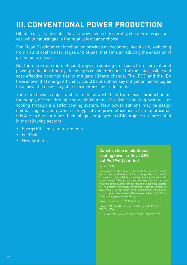
III.CONVENTIONALPOWERPRODUCTIONOil and coal, in particular, have always been considerably cheaper energy sour-ces, while natural gas is the relatively cleaner choice.
The Clean Development Mechanism provides an economic incentive to switching from oil and coal to natural gas or biofuels, that aims at reducing the emission of greenhouse gasses.
But there are even more efficient ways of reducing emissions from conventional power production. Energy efficiency is considered one of the most accessible and cost-effective opportunities to mitigate climate change. The IPCC and the IEA have shown that energy efficiency could be one of the key mitigation technologies to achieve the necessary short term emissions reductions.
There are obvious opportunities to utilise waste heat from power production for the supply of heat through the establishment of a district heating system – or cooling through a district cooling system. New power stations may be desig-ned for cogeneration, which can typically improve efficiencies from approxima-tely 40% to 80%, or more. Technologies employed in CDM projects are presented in the following sectors:
• Energy Efficiency Improvements• Fuel Shift• New Systems
ConstructionofadditionalcoolingtowercellsatAESLalPir(Pvt.)LimitedRef. no. 2401
The purpose of the project is to utilise the latest technology to improve the heat rate of the power plants, which entails construction of an additional cooling tower cell for each unit’s cooling tower. A better heat rate will lower CO
2 emissions by
reducing in the quantity of fuel required to generate electrici-ty. The efficiency improvement program under the project ac-tivity consists of the construction of additional cooling tower cells, installation of advanced technology and mechanical wor-ks including piping, connections, etc.
Project investment: USD 1.6 million
Project CO2 reduction over a crediting period of 7 years:
78,252 tCO2e
Expected CER revenue (CER/USD 10): USD 782,520
30
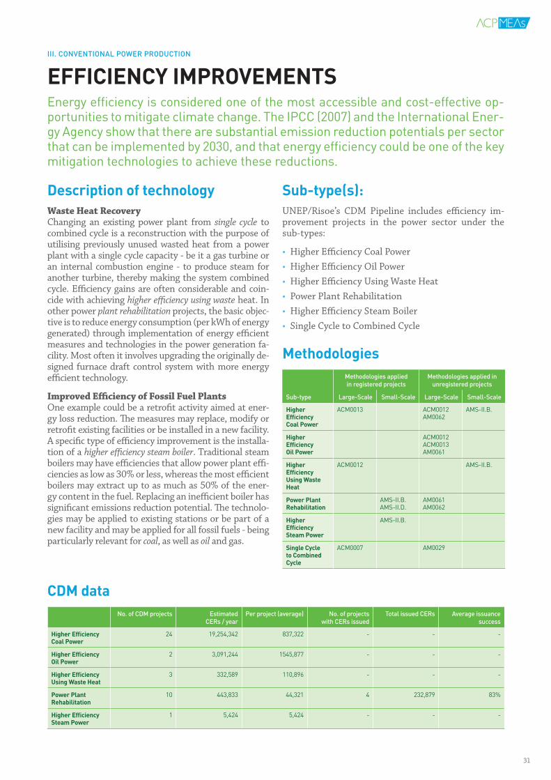
DescriptionoftechnologyWaste Heat RecoveryChanging an existing power plant from single cycle to combined cycle is a reconstruction with the purpose of utilising previously unused wasted heat from a power plant with a single cycle capacity - be it a gas turbine or an internal combustion engine - to produce steam for another turbine, thereby making the system combined cycle. Efficiency gains are often considerable and coin-cide with achieving higher efficiency using waste heat. In other power plant rehabilitation projects, the basic objec-tive is to reduce energy consumption (per kWh of energy generated) through implementation of energy efficient measures and technologies in the power generation fa-cility. Most often it involves upgrading the originally de-signed furnace draft control system with more energy efficient technology.
Improved Efficiency of Fossil Fuel PlantsOne example could be a retrofit activity aimed at ener-gy loss reduction. The measures may replace, modify or retrofit existing facilities or be installed in a new facility. A specific type of efficiency improvement is the installa-tion of a higher efficiency steam boiler. Traditional steam boilers may have efficiencies that allow power plant effi-ciencies as low as 30% or less, whereas the most efficient boilers may extract up to as much as 50% of the ener-gy content in the fuel. Replacing an inefficient boiler has significant emissions reduction potential. The technolo-gies may be applied to existing stations or be part of a new facility and may be applied for all fossil fuels - being particularly relevant for coal, as well as oil and gas.
Sub-type(s):UNEP/Risoe’s CDM Pipeline includes efficiency im-provement projects in the power sector under the sub-types:
• Higher Efficiency Coal Power • Higher Efficiency Oil Power • Higher Efficiency Using Waste Heat• Power Plant Rehabilitation • Higher Efficiency Steam Boiler • Single Cycle to Combined Cycle
MethodologiesMethodologies applied in registered projects
Methodologies applied in unregistered projects
Sub-type Large-Scale Small-Scale Large-Scale Small-Scale
HigherEfficiencyCoalPower
ACM0013 ACM0012AM0062
AMS-II.B.
HigherEfficiencyOilPower
ACM0012ACM0013AM0061
HigherEfficiencyUsingWasteHeat
ACM0012 AMS-II.B.
PowerPlantRehabilitation
AMS-II.B.AMS-II.D.
AM0061AM0062
HigherEfficiencySteamPower
AMS-II.B.
SingleCycletoCombinedCycle
ACM0007 AM0029
CDMdataNo. of CDM projects Estimated
CERs / yearPer project (average) No. of projects
with CERs issuedTotal issued CERs Average issuance
success
HigherEfficiencyCoalPower
24 19,254,342 837,322 - - -
HigherEfficiencyOilPower
2 3,091,244 1545,877 - - -
HigherEfficiencyUsingWasteHeat
3 332,589 110,896 - - -
PowerPlantRehabilitation
10 443,833 44,321 4 232,879 83%
HigherEfficiencySteamPower
1 5,424 5,424 - - -
EFFICIENCYIMPROVEMENTSEnergy efficiency is considered one of the most accessible and cost-effective op-portunities to mitigate climate change. The IPCC (2007) and the International Ener-gy Agency show that there are substantial emission reduction potentials per sector that can be implemented by 2030, and that energy efficiency could be one of the key mitigation technologies to achieve these reductions.
III. CONVENTIONAL POWER PRODUCTION
31
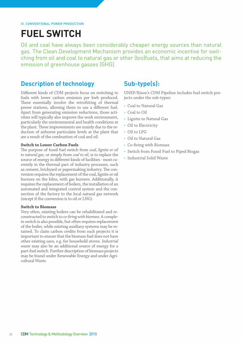
DescriptionoftechnologyDifferent kinds of CDM projects focus on switching to fuels with lower carbon emission per kwh produced. These essentially involve the retrofitting of thermal power stations, allowing them to use a different fuel. Apart from generating emission reductions, those acti-vities will typically also improve the work environment, particularly the environmental and health conditions at the plant. These improvements are mainly due to the re-duction of airborne particulate levels at the plant that are a result of the combustion of coal and oil.
Switch to Lower Carbon FuelsThe purpose of fossil fuel switch from coal, lignite or oil to natural gas, or simply from coal to oil, is to replace the source of energy in different kinds of facilities - most cu-rrently in the thermal part of industry processes, such as cement, brickyard or papermaking industry. The con-version requires the replacement of the coal, lignite or oil burners on the kilns, with gas burners. Additionally, it requires the replacement of boilers, the installation of an automated and integrated control system and the con-nection of the factory to the local natural gas network (except if the conversion is to oil or LNG).
Switch to BiomassVery often, existing boilers can be rehabilitated and re-constructed to switch to co-firing with biomass. A comple-te switch is also possible, but often requires replacement of the boiler, while existing auxiliary systems may be re-tained. To claim carbon credits from such projects it is important to ensure that the biomass fuel does not have other existing uses, e.g. for household stoves. Industrial waste may also be an additional source of energy for a part-fuel switch. Further description of biomass projects may be found under Renewable Energy and under Agri-cultural Waste.
Sub-type(s):UNEP/Risoe’s CDM Pipeline includes fuel switch pro-jects under the sub-types:
• Coal to Natural Gas • Coal to Oil • Lignite to Natural Gas• Oil to Electricity • Oil to LPG• Oil to Natural Gas• Co-firing with Biomass• Switch from Fossil Fuel to Piped Biogas• Industrial Solid Waste
FUELSWITCHOil and coal have always been considerably cheaper energy sources than natural gas. The Clean Development Mechanism provides an economic incentive for swit-ching from oil and coal to natural gas or other (bio)fuels, that aims at reducing the emission of greenhouse gasses (GHG).
III. CONVENTIONAL POWER PRODUCTION
CDM Technology & Methodology Overview 201032
CDMdataNo. of CDM projects Estimated
CERs / yearPer project (average) No. of projects
with CERs issuedTotal issued CERs Average issuance
success
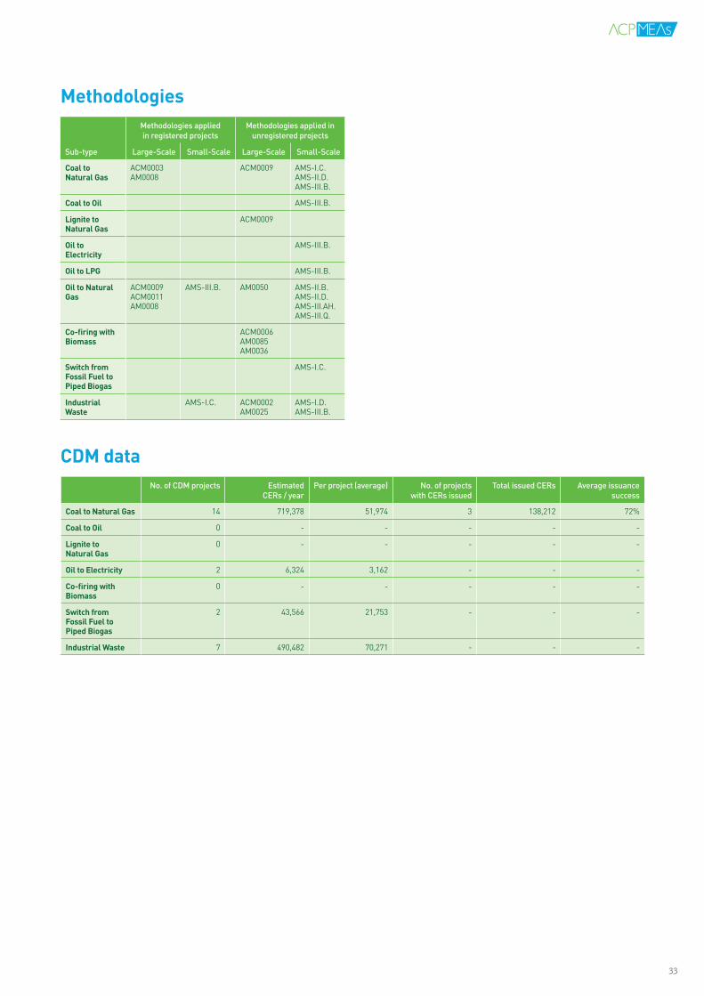
CoaltoNaturalGas 14 719,378 51,974 3 138,212 72%
CoaltoOil 0 - - - - -
LignitetoNaturalGas
0 - - - - -
OiltoElectricity 2 6,324 3,162 - - -
Co-firingwithBiomass
0 - - - - -
SwitchfromFossilFueltoPipedBiogas
2 43,566 21,753 - - -
IndustrialWaste 7 490,482 70,271 - - -
MethodologiesMethodologies applied in registered projects
Methodologies applied in unregistered projects
Sub-type Large-Scale Small-Scale Large-Scale Small-Scale
CoaltoNaturalGas
ACM0003AM0008
ACM0009 AMS-I.C.AMS-II.D.AMS-III.B.
CoaltoOil AMS-III.B.
LignitetoNaturalGas
ACM0009
OiltoElectricity
AMS-III.B.
OiltoLPG AMS-III.B.
OiltoNaturalGas
ACM0009ACM0011AM0008
AMS-III.B. AM0050 AMS-II.B.AMS-II.D.AMS-III.AH.AMS-III.Q.
Co-firingwithBiomass
ACM0006AM0085AM0036
SwitchfromFossilFueltoPipedBiogas
AMS-I.C.
IndustrialWaste
AMS-I.C. ACM0002AM0025
AMS-I.D.AMS-III.B.
33

CogenerationNew systems in the power sector – as opposed to rehabi-litating or reconstructing existing systems – involve the establishment of new heating systems or the construc-tion of new efficient power plants. Cogeneration is the use of a heat engine or power station to simultaneously generate both electricity and heat. In separate produc-tion of electricity approximately half the energy content that could be used as heat is lost. By recovering this loss, cogeneration has a considerable potential for emissions reductions as such projects are generally large-scale. The technology used is commonly a Combined Cycle Power Plant that employs more than one thermodynamic cy-cle (e.g. a Brayton cycle and Rankine cycle), consequently exploiting the otherwise wasted heat.
Natural GasIn countries with potential for natural gas or LNG based power production, but where little or no utilisation is ta-king place, new natural gas fired power plants may be re-gistered as CDM projects. Natural gas is a relatively clean energy with less carbon content than coal and oil. Dis-placing electricity that would otherwise have been gene-rated by coal-fired thermal plants, therefore, is a sour-ce of emissions reduction. For natural gas fired power plants, there is a specific Natural Gas Fired Combined Cycle (NGCC) technology available. The cycle efficiency of natural gas based combined cycle power plants is in the range of 50-55%, as compared to the average cycle efficiency of 36-42% for coal fired Rankine cycle based thermal power plants. Therefore, the NGCC technology has a much higher efficiency than conventional coal fi-red steam power generator units, while at the same time being comparably modest in capital construction cost - with a short construction period and fewer require-ments for land and water resources than coal fired power plants.
Sub-type(s):UNEP/Risoe’s CDM Pipeline includes new systems projects in the power sector under the sub-types:
• Cogeneration • New Natural Gas Plant• New Natural Gas Plant Using LNG
CDMdataNo. of CDM projects Estimated
CERs / yearPer project (average) No. of projects
with CERs issuedTotal issued CERs Average issuance
success
Cogeneration 26 1,329,289 51,356 2 26,543 89%
NewNaturalGasPlant
53 34,456,390 663,219 10 3,973,298 69%
NewNaturalGasPlantUsingLNG
9 11,213,489 1,246,775 1 71,578 46%
NEWSYSTEMSWhen expanding the energy supply systems through conventional sources some options are less emission intensive than others. In colder regions there are obvious opportunities to utilise waste heat from power production for the supply of heat through the establishment of a district heating system. Alternatively, new power stations may be designed for cogeneration at the outset, typically increasing effi-ciencies from approximately 40% to 80%, or more. New generation capacity may also employ low emission natural gas or LNG instead of traditional coal firing, creating possibilities for significant emissions reductions.
Descriptionoftechnology
MethodologiesMethodologies applied in registered projects
Methodologies applied in unregistered projects
Sub-type Large-Scale Small-Scale Large-Scale Small-Scale
Cogeneration AM0014 AMS-II.B.AMS-II.H.
ACM0002ACM0006AM0014AM0048AM0084
AMS-I.D.AMS-II.D.AMS-II.E.AMS-III.B.AMS-III.Q.
NewNaturalGasPlant
ACM0002AM0029
ACM0013AM0049
NewNaturalGasPlantUsingLNG
ACM0002AM0029
III. CONVENTIONAL POWER PRODUCTION
CDM Technology & Methodology Overview 201034

IV.HEATINGSYSTEMSIn countries where heating is needed in the winter, significant savings are often possible by improving the efficiency of existing heating systems. This could be as simple as reducing heat loss in the system by preventing leakage or increasing insulation. However, efficiency may also be increased with the replacement of in-efficient boilers or utilising waste heat from industrial production.
In areas with geological faults there are particular options for utilisation of geo-thermal heating or geothermal power production. But in most areas, low tempe-rature geothermal heating is an option that is rarely utilised despite offering sig-nificant potential for emissions reduction.
Significant efficiency gains may be achieved through metering and payment sys-tems that allow consumers to regulate the heat and reduce costs accordingly. Most of the heat loss in heating systems is often caused by lack of incentives for saving excess energy. Households are an important target for initiatives in this regard.
These considerations apply equally to cooling systems that may not be individua-lly metered, or where equipment is installed by developers that have no interest in subsequent running costs and energy savings.
Heating projects are divided between the following:
• Efficiency Improvements• New Systems AmatitlanGeothermalProject
byOrtitlanLimitadaRef. no. 2022
The Amatitlan Geothermal Project is a geothermal power plant in the Department of Escuintla, in Guatemala. Total ins-talled capacity of the project will be 25.2 MW, with an actual net capacity of 20.5 MW. The plant will utilise three turbines (two with installed capacities of 12 MW each, and one at 1.2 MW) and has a predicted power generation of 162,000 MWh per annum. The purpose of the project is to utilise the geologi-cal resources of the Amatitlan Geothermal Field in a state-of-the-art geothermal power plant to generate renewable energy that will be dispatched to the grid.
Project investment: N.A.
Project CO2 reduction over a crediting period of 7 years:
580,849 tCO2e
Expected CER revenue (CER/USD 10): USD 5,808,490
35
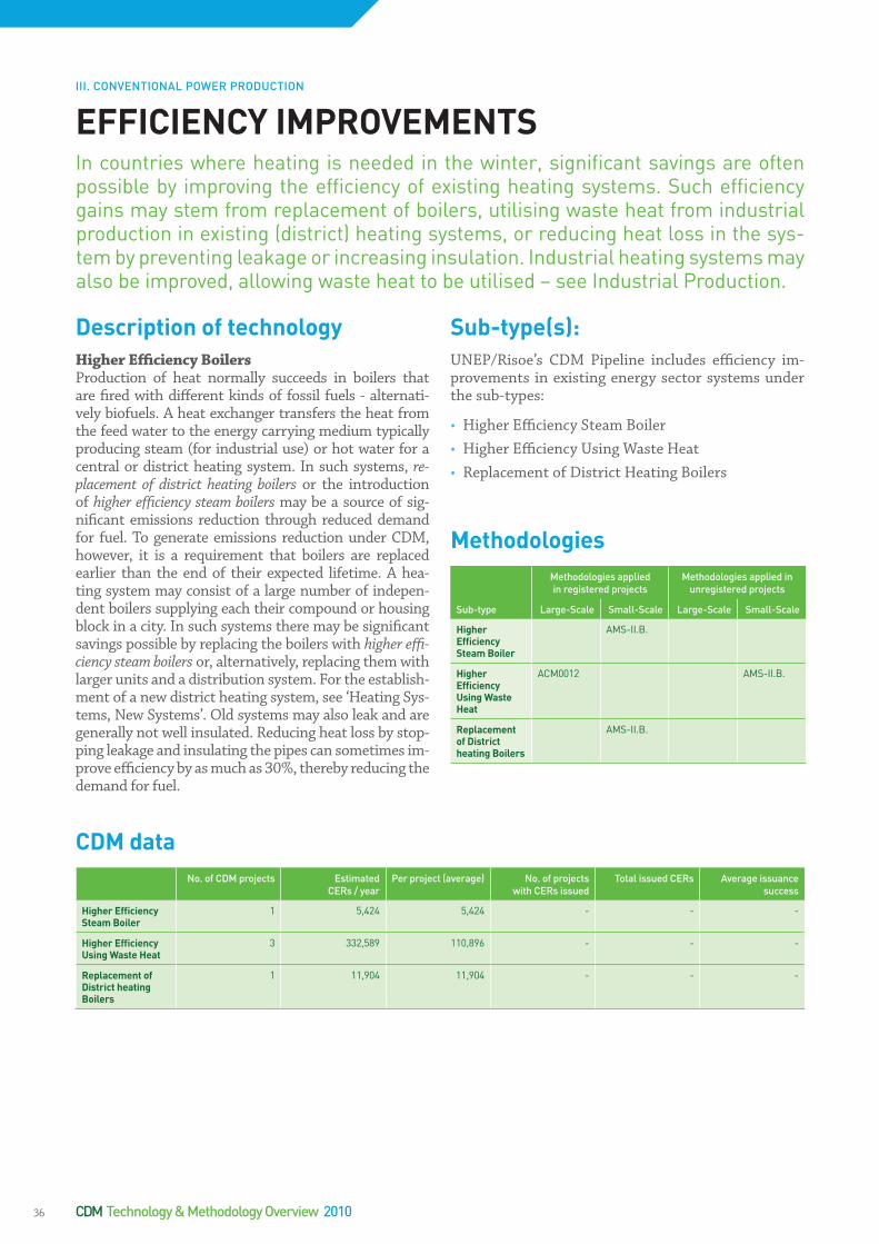
DescriptionoftechnologyHigher Efficiency BoilersProduction of heat normally succeeds in boilers that are fired with different kinds of fossil fuels - alternati-vely biofuels. A heat exchanger transfers the heat from the feed water to the energy carrying medium typically producing steam (for industrial use) or hot water for a central or district heating system. In such systems, re-placement of district heating boilers or the introduction of higher efficiency steam boilers may be a source of sig-nificant emissions reduction through reduced demand for fuel. To generate emissions reduction under CDM, however, it is a requirement that boilers are replaced earlier than the end of their expected lifetime. A hea-ting system may consist of a large number of indepen-dent boilers supplying each their compound or housing block in a city. In such systems there may be significant savings possible by replacing the boilers with higher effi-ciency steam boilers or, alternatively, replacing them with larger units and a distribution system. For the establish-ment of a new district heating system, see ‘Heating Sys-tems, New Systems’. Old systems may also leak and are generally not well insulated. Reducing heat loss by stop-ping leakage and insulating the pipes can sometimes im-prove efficiency by as much as 30%, thereby reducing the demand for fuel.
Sub-type(s):UNEP/Risoe’s CDM Pipeline includes efficiency im-provements in existing energy sector systems under the sub-types:
• Higher Efficiency Steam Boiler• Higher Efficiency Using Waste Heat• Replacement of District Heating Boilers
CDMdataNo. of CDM projects Estimated
CERs / yearPer project (average) No. of projects
with CERs issuedTotal issued CERs Average issuance
success
HigherEfficiencySteamBoiler
1 5,424 5,424 - - -
HigherEfficiencyUsingWasteHeat
3 332,589 110,896 - - -
ReplacementofDistrictheatingBoilers
1 11,904 11,904 - - -
EFFICIENCYIMPROVEMENTSIn countries where heating is needed in the winter, significant savings are often possible by improving the efficiency of existing heating systems. Such efficiency gains may stem from replacement of boilers, utilising waste heat from industrial production in existing (district) heating systems, or reducing heat loss in the sys-tem by preventing leakage or increasing insulation. Industrial heating systems may also be improved, allowing waste heat to be utilised – see Industrial Production.
MethodologiesMethodologies applied in registered projects
Methodologies applied in unregistered projects
Sub-type Large-Scale Small-Scale Large-Scale Small-Scale
HigherEfficiencySteamBoiler
AMS-II.B.
HigherEfficiencyUsingWasteHeat
ACM0012 AMS-II.B.
ReplacementofDistrictheatingBoilers
AMS-II.B.
III. CONVENTIONAL POWER PRODUCTION
CDM Technology & Methodology Overview 201036

District HeatingA district heating system works by heating water that is then pumped around an underground district heating ring-main pipe. The pipe carries this heated water into buildings connected to the district heating system. Each building is fitted with a heat exchanger, which allows the heat it requires to be taken from the ring-main. For sys-tems serving housing developments, the heat is used for both the living space and domestic hot water. The tech-nology may be applied to existing power plants, turning it into a cogeneration facility, or be part of a new facility planned for the supply of both power and district hea-ting. Projects may also involve introduction of new mo-dern heat boilers to supplement heat from an existing power plant. Apart from providing higher energy effi-ciency, district heating plants facilitate better pollution control than localised boilers. These systems may also be employed for cooling purposes and a number of ‘tri-generation’ (heating, cooling and power) have recently emerged, also as CDM projects.
Geothermal Heating SystemsIn some areas geothermal heating may be extracted from underground. Geological activity along fault lines bet-ween the earth’s tectonic plates is often accompanied by higher temperatures closer to the surface. This ener-gy may be harvested through piping systems going deep underground, possibly 1000 metres or more, where feed water is heated and led to a heat exchanger from which heated water is supplied to a district heating system. Al-ternatively, if temperatures are sufficient, steam is pro-duced to run a turbine and generator system for the pro-duction of electricity.
Another type of heat supply, which is also often labeled ‘geothermal energy’ is the low temperature heat extrac-ted from approximately 1½ metres underground - ex-ploiting the fact that at this depth the temperature is quite constant at 8oC. More accurately, however, this is referred to as heat pumping; employing the same prin-ciple as in a refrigerator. Such heat pumping is also pos-sible from air and can typically produce approximately three times as much energy (electricity) as is required to run the process. Such systems are usually employed in low or zero-energy individual housing.
Sub-type(s):UNEP/Risoe’s CDM Pipeline includes efficiency im-provements in existing energy sector systems under the sub-types:
• Geothermal Heating• Cogeneration • District Heating
CDMdataNo. of CDM projects Estimated
CERs / yearPer project (average) No. of projects
with CERs issuedTotal issued CERs Average issuance
success
GeothermalHeating
2 99,221 49,611 - - -
Cogeneration 26 1,329,289 51,356 2 26,543 89%
DistrictHeating 11 5,261,356 478,392 - - -
NEWSYSTEMSThere is a large potential for greenhouse gas emissions reduction from district or distributed heating systems. This can be achieved by changing the source of heat, constructing new cogeneration systems, i.e. combined heat and power production, or establishing a district heating system in connection with existing power plants.
MethodologiesMethodologies applied in registered projects
Methodologies applied in unregistered projects
Sub-type Large-Scale Small-Scale Large-Scale Small-Scale
GeothermalHeating
AM0072 AMS-I.C.
Cogeneration AM0014 AMS-II.B.AMS-II.H.
ACM0002ACM0006AM0048AM0072AM0084
AMS-I.D.AMS-II.D.AMS-II.E.AMS-III.B.AMS-III.Q.
DistrictHeating
AM0058
Descriptionoftechnology
III. CONVENTIONAL POWER PRODUCTION
37

V.RENEWABLEENERGYRenewable energy is likely the most intuitive response to the climate challenge due to the technologies’ zero-emission qualities. It is a very diverse group of te-chnologies including biomass, solar energy, wind, hydro, geothermal and tidal energy.
Biomass is a hugely diverse group of projects. It encompasses biofuels, energy production from biomass waste, gasification and utilisation of liquid wastes such as manure. It accounts for approximately 15% of global primary energy use and 38% of the primary energy use in developing countries.
Harnessing the sun’s energy is less diverse and succeeds in two distinct ways. Solar thermal energy exploits solar energy for heat production, either at low temperatures commonly used in households, or high temperatures for steam and power production. Photovoltaic (PVs) is generating electric power by using solar cells to directly convert energy from the sun into electricity.
The installation of wind turbines continues to accelerate, while turbines are growing in size and increasingly moving to sea in off-shore installations. Cu-rrently, 80 countries use wind for power production reaching close to 2% of the world’s electricity.
Geothermal energy is increasing rapidly, though still at a significantly lower le-vel than wind energy, while hydro projects – beyond doubt the oldest form of re-newable energy – supply 20% of world electricity through dams or run-of-the-river projects.
Lastly, and much less mature, is the technology for utilisation of tidal forces. In places with shallow waters, narrow fiords or inlets, the difference between high and low tide can be as much as 20 metres. Such places have tremendous forces that can be exploited for energy production.
CDM projects are found in all of the following categories:
• Biomass• Hydro• Wind• Solar• Geothermal• Tidal
SantaCruzIHydroPowerPlantRef. no. 2405
The CDM project is a run-of-river hydropower plant, located north east of Peru’s capital city of Lima at 1,985 meters abo-ve sea level in the basin of the Blanco River (Santa Cruz) in the district of Colcas. The plant will have an installed capacity of 5.9 megawatts and a projected yearly average generation of 35,827 megawatt hours. The objective of the Santa Cruz I Hydroelectric Power Plant is renewable electricity genera-tion to be supplied to the Peruvian National Inter-connected Electric Grid.
Project investment: USD 7,500,000
Project CO2 reduction over a crediting period of 7 years:
118,490 tCO2e
Expected CER revenue (CER/USD 10): USD 1,184,900
38
Biomass refers to non-fossilised and biodegradable or-ganic material originating from plants, animals and mi-croorganisms. Biomass also includes non-fossilised, bio-degradable organic fractions of municipal and industrial wastes as well as products, by-products, residues and waste from agriculture and forestry related industries. The most common examples are sugar cane waste (ba-gasse), palm oil solid waste, short rotation crops such as straw and husks, organic wastes from animal husbandry, energy crops, corn and trees grown in short-rotation plantations. Biomass is a widely distributed, but variable resource that can be converted to biomass energy in the form of heat and electricity. In addition to potential gre-enhouse abatement benefits, biomass energy projects can address many other environmental issues such as decreasing soil erosion, controlling nitrogen runoff, and protecting watersheds.
Combustion of Biomass ResiduesThe main processes for obtaining energy from these bio-mass sources include direct combustion, usually of so-lids, in boilers or furnaces and gasification via a physical or chemical conversion process to a secondary gaseous fuel. A biomass energy project can be designed to coge-nerate both heat and electricity, increasing its overall energy efficiency and financial viability. Such projects may also create a cost-effective solution to the disposal of agricultural or industrial wastes that may otherwise become potential environmental problems. Biomass combustion projects can be as large as 100 MW power stations generating both electricity and heat.
Household InstallationsProjects may be small enough to produce the lighting and cooking energy for a single household or village. At this level, one of the most common technologies to utilise biomass energy is the household cook stove. The Programmatic CDM approach may conceivably be able to unlock the potential for small-scale biomass projects. See further under Household Systems, where gasifica-tion of domestic manure is also described as an option for emissions reduction; large-scale manure utilisation can be found under Liquid Waste.
Industrial Biomass OptionsIn biomass related industries, occasionally, there are op-tions for utilising waste for energy production. To ma-nufacture pulp for paper, cardboard etc., wood chips are boiled at high pressure and temperature to remove the lignin that holds the fibres together. Approximately half of the original energy content is left in the fibres of the paper, while the rest ends up in the used cooking liquor, which is called black liquor. The black liquor may either be gasified or turned into biofuel.
BiofuelsBiomass may either be grown as dedicated fuel crops (e.g. jatropha) or biomass waste may be turned into bio-fuels. Biodiesel, methanol and bioethanol can all repla-ce hydrocarbon fuels, thereby reducing GHG emissions. Bioethanol is widespread based on first generation te-chnology that uses food crops, while second generation bioethanol is employing enzymes to extract sugar from stalks and other waste, thus, not competing with food production. Briquettes may be produced from other bio-mass residues, while charcoal may be produced from fo-rest residues in more efficient and lower methane emit-ting production facilities.
BIOMASSBiomass is a hugely diverse group of projects. As such, it is recommended to ex-plore it under Agricultural Waste, Solid Waste and Liquid Waste in order to get a more detailed picture. Biomass accounts for approximately 15% of global primary energy use and 38% of the primary energy use in developing countries. More than 80% of biomass energy is used at low efficiencies for cooking, heating and lighting by more than two billion consumers - many of whom rely on traditional biomass fuels and/or have no access to modern energy services. Dependence on traditional biomass is far greater in sub-Saharan Africa than any other region of the world.
Descriptionoftechnology
V. RENEWABLE ENERGY
39
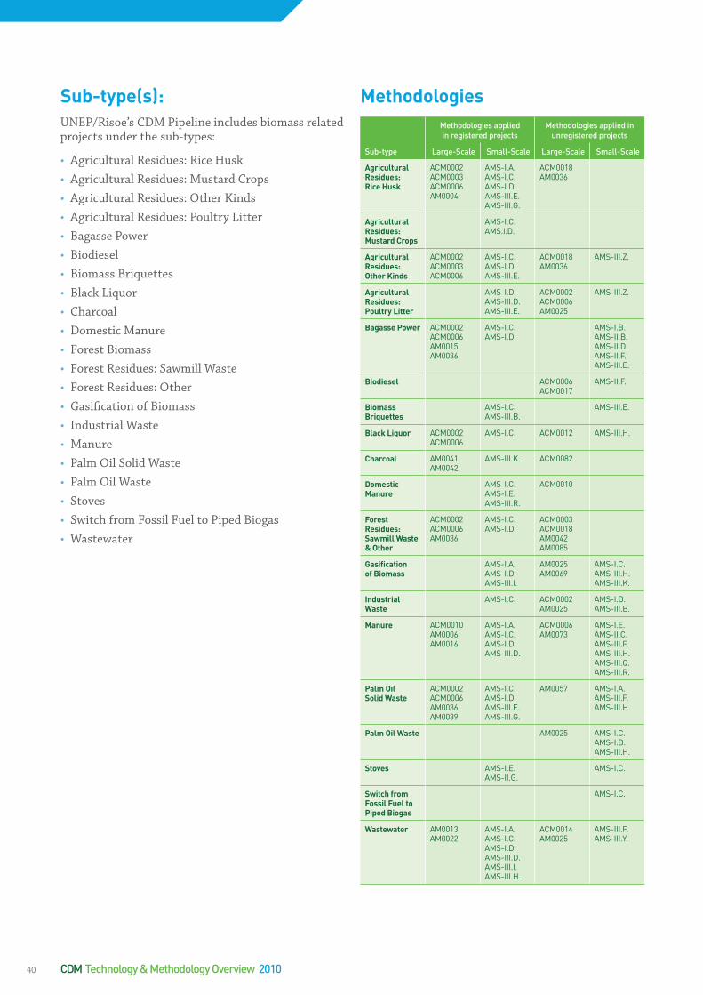
Sub-type(s):UNEP/Risoe’s CDM Pipeline includes biomass related projects under the sub-types:
• Agricultural Residues: Rice Husk• Agricultural Residues: Mustard Crops• Agricultural Residues: Other Kinds • Agricultural Residues: Poultry Litter• Bagasse Power• Biodiesel• Biomass Briquettes• Black Liquor• Charcoal• Domestic Manure• Forest Biomass• Forest Residues: Sawmill Waste • Forest Residues: Other• Gasification of Biomass• Industrial Waste• Manure• Palm Oil Solid Waste• Palm Oil Waste• Stoves• Switch from Fossil Fuel to Piped Biogas• Wastewater
MethodologiesMethodologies applied in registered projects
Methodologies applied in unregistered projects
Sub-type Large-Scale Small-Scale Large-Scale Small-Scale
AgriculturalResidues:RiceHusk
ACM0002ACM0003ACM0006AM0004
AMS-I.A.AMS-I.C.AMS-I.D.AMS-III.E.AMS-III.G.
ACM0018AM0036
AgriculturalResidues:MustardCrops
AMS-I.C.AMS.I.D.
AgriculturalResidues:OtherKinds
ACM0002ACM0003ACM0006
AMS-I.C.AMS-I.D.AMS-III.E.
ACM0018AM0036
AMS-III.Z.
AgriculturalResidues:PoultryLitter
AMS-I.D.AMS-III.D.AMS-III.E.
ACM0002ACM0006AM0025
AMS-III.Z.
BagassePower ACM0002ACM0006AM0015AM0036
AMS-I.C.AMS-I.D.
AMS-I.B.AMS-II.B.AMS-II.D.AMS-II.F.AMS-III.E.
Biodiesel ACM0006ACM0017
AMS-II.F.
BiomassBriquettes
AMS-I.C.AMS-III.B.
AMS-III.E.
BlackLiquor ACM0002ACM0006
AMS-I.C. ACM0012 AMS-III.H.
Charcoal AM0041AM0042
AMS-III.K. ACM0082
DomesticManure
AMS-I.C.AMS-I.E.AMS-III.R.
ACM0010
ForestResidues:SawmillWaste&Other
ACM0002ACM0006AM0036
AMS-I.C.AMS-I.D.
ACM0003ACM0018AM0042AM0085
GasificationofBiomass
AMS-I.A.AMS-I.D.AMS-III.I.
AM0025AM0069
AMS-I.C.AMS-III.H.AMS-III.K.
IndustrialWaste
AMS-I.C. ACM0002AM0025
AMS-I.D.AMS-III.B.
Manure ACM0010AM0006AM0016
AMS-I.A.AMS-I.C.AMS-I.D.AMS-III.D.
ACM0006AM0073
AMS-I.E.AMS-II.C.AMS-III.F.AMS-III.H.AMS-III.Q.AMS-III.R.
PalmOilSolidWaste
ACM0002ACM0006AM0036AM0039
AMS-I.C.AMS-I.D.AMS-III.E.AMS-III.G.
AM0057 AMS-I.A.AMS-III.F.AMS-III.H
PalmOilWaste AM0025 AMS-I.C.AMS-I.D.AMS-III.H.
Stoves AMS-I.E.AMS-II.G.
AMS-I.C.
SwitchfromFossilFueltoPipedBiogas
AMS-I.C.
Wastewater AM0013AM0022
AMS-I.A.AMS-I.C.AMS-I.D.AMS-III.D.AMS-III.I.AMS-III.H.
ACM0014AM0025
AMS-III.F.AMS-III.Y.
CDM Technology & Methodology Overview 201040

CDMdataNo. of CDM projects Estimated
CERs / yearPer project (average) No. of projects
with CERs issuedTotal issued CERs Average issuance
success
AgriculturalResidues:RiceHusk
160 8,739,190 56,112 29 2,530,801 95%
AgriculturalResidues:MustardCrops
10 320,521 32,188 1 145,820 100%
AgriculturalResidues:OtherKinds
197 16,739,000 86,821 86 3,228,192 90%
AgriculturalResidues:PoultryLitter
5 378,982 76,213 - - -
BagassePower 152 6,757,421 44,132 47 4,891,812 96%
Biodiesel 3 224,232 74,894 - - -
BiomassBriquettes 13 181,449 14,743 2 31,766 90,8%
BlackLiquor 11 1,390,329 126,463 1 186,398 297%
Charcoal 4 322,231 81,139 - - -
DomesticManure 17 734,312 43,821 11,761 1,761 60%
ForestResidues:sawmillwaste&other
59 2,181,543 74,332 8 2,902,000 89%
GasificationofBiomass
14 282,244 20,289 - - -
Industrialwaste 7 490,482 70,271 - - -
Manure 263 11,358,391 43,291 51 5,223,211 48%
PalmOilSolidWaste
48 3,279,802 68,421 24 457,192 61%
PalmOilWaste 8 276,412 34,124 - - -
Stoves 17 431,324 25,674 - - -
SwitchFromFossilFuelToPipedBiogas
2 43,378 21,689 - - -
WasteWater 253 12,511,840 50,234 11 1,397,234 109%
41
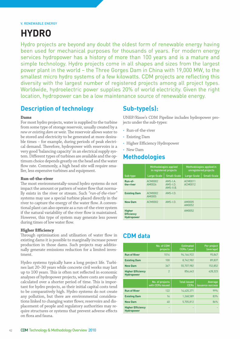
DescriptionoftechnologyDamsFor most hydro projects, water is supplied to the turbine from some type of storage reservoir, usually created by a new or existing dam or weir. The reservoir allows water to be stored and electricity to be generated at more desira-ble times – for example, during periods of peak electri-cal demand. Therefore, hydropower with reservoirs is a very good ‘balancing capacity’ in an electrical supply sys-tem. Different types of turbines are available and the op-timum choice depends greatly on the head and the water flow rate. Commonly, a high head site will require sma-ller, less expensive turbines and equipment.
Run-of-the-riverThe most environmentally-sound hydro systems do not impact the amount or pattern of water flow that norma-lly exists in the river or stream. Such “run-of-the-river” systems may use a special turbine placed directly in the river to capture the energy of the water flow. A conven-tional plant can also operate as a run-of-the-river system if the natural variability of the river flow is maintained. However, this type of system may generate less power during times of low water flow.
Higher EfficiencyThrough optimisation and utilisation of water flow in existing dams it is possible to marginally increase power production in those dams. Such projects may additio-nally generate emissions reduction for a limited inves-tment.
Hydro systems typically have a long project life. Turbi-nes last 20–30 years while concrete civil works may last up to 100 years. This is often not reflected in economic analyses of hydropower projects, where costs are usually calculated over a shorter period of time. This is impor-tant for hydro projects, as their initial capital costs tend to be comparatively high. Hydro systems do not create any pollution, but there are environmental considera-tions linked to changing water flows; reservoirs and dis-placement of people and regulatory authorities may re-quire structures or systems that prevent adverse effects on flora and fauna.
Sub-type(s):UNEP/Risoe’s CDM Pipeline includes hydropower pro-jects under the sub-types:
• Run-of-the-river • Existing Dam• Higher Efficiency Hydropower• New Dam
HYDROHydro projects are beyond any doubt the oldest form of renewable energy having been used for mechanical purposes for thousands of years. For modern energy services hydropower has a history of more than 100 years and is a mature and simple technology. Hydro projects come in all shapes and sizes from the largest power plant in the world – the Three Gorges Dam in China with 19,000 MW, to the smallest micro hydro systems of a few kilowatts. CDM projects are reflecting this diversity with the largest number of registered projects among all project types. Worldwide, hydroelectric power supplies 20% of world electricity. Given the right location, hydropower can be a low maintenance source of renewable energy.
CDMdataNo. of CDM
projects Estimated
CERs / yearPer project
(average)
RunofRiver 1014 94,166,922 95,847
ExistingDam 100 8,742,982 89,837
NewDam 367 55,707,982 152,852
HigherEfficiencyHydropower
2 856,643 428,323
No. of projects with CERs issued
Total issued CERs
Average issuance success
RunofRiver 122 14,620,371 99%
ExistingDam 16 1,268,589 83%
NewDam 40 5,705,812 86%
HigherEfficiencyHydropower
- - -
MethodologiesMethodologies applied in registered projects
Methodologies applied in unregistered projects
Sub-type Large-Scale Small-Scale Large-Scale Small-Scale
Run-of-the-river
ACM0002AM0026
AMS-I.A.AMS-I.D.AMS-II.B.
ACM0011ACM0012
ExistingDam ACM0002AM0005
AMS-I.D.
NewDam ACM0002 AMS-I.D. AM0005AM0052
HigherEfficiencyHydropower
AM0052
V. RENEWABLE ENERGY
CDM Technology & Methodology Overview 201042

DescriptionoftechnologyWind turbines for large-scale energy production have been developed over the past 25-30 years and are the most competitive renewable source of energy compa-red to fossil fuels. Turbines are typically using a gearbox before the generator to compensate for differing wind speeds though some direct drive turbines have also rea-ched the market. Utility-sized commercial wind pro-jects are usually constructed as wind farms where seve-ral turbines are put up at the same site. By far the most common installation is grid connected wind farms that supply electricity to the public electricity grid. The pene-tration rate of wind energy is growing rapidly and some countries have had shares of wind energy in power pro-duction of 5-10%, or even as high as 25% in Denmark, without disturbing the stability of the grid. Such rates, however, require storage capacity or cross-border trans-mission options as well as advanced turbine technology such as Low Voltage Ride Through (LVRT).
A modern wind turbine in a good location should ge-nerate power corresponding to 2000-3000 ‘full-load hours’ in a year (a normal power plant is approximately 7500-8000 full-load hours/year). Prime sites have ave-rage wind speeds greater than 7.5 metres/second. Mo-dern turbines being installed today have a power capa-city of 1.5-2.5 MW. Off-shore turbines are larger and currently the largest turbines available commercially are 5MW. The research and development trend among ma-jor manufacturers is towards even larger turbines on ta-ller towers as wind speeds increase with greater height above the ground. However, in low speed wind regimes smaller turbines may be more efficient.
Wind projects have been successfully built to power a wide range of applications in diverse and often extreme environments. In off-grid applications, wind generators can be combined with other energy sources, such as die-sel generators.
Sub-type(s):UNEP/Risoe’s CDM Pipeline includes wind energy pro-jects under the sub-type:
• Wind
MethodologiesMethodologies applied in registered projects
Methodologies applied in unregistered projects
Sub-type Large-Scale Small-Scale Large-Scale Small-Scale
Wind ACM0002 AMS-I.D. AMS-I.F.
WINDGlobal wind capacity increased by approximately 37,500 MW in 2009 ending the year at a cumulative capacity of 157,913 MW. With cumulative installations up al-most 31%, the growth rate exceeded the annual average of the past decade. The wind now generates close to 2% of the world’s electricity - up from 0.1% in 1997. Around the world, 80 countries are now using wind power on a commercial basis.
CDMdataNo. of CDM projects Estimated
CERs / yearPer project (average) No. of projects
with CERs issuedTotal issued CERs Average issuance
success
Wind 1029 107,543,345 92,387 162 21,958,879 89%
V. RENEWABLE ENERGY
43

The sun’s energy can be collected directly to create both high temperature steam (greater than 100oC) and low temperature heat (less than 100oC) for use in a variety of heat and power applications.
Solar ThermalHigh temperature solar thermal systems use mirrors and other reflective surfaces to concentrate solar radia-tion. Parabolic dish systems concentrate solar radiation to a single point to produce temperatures in excess of 1000oC. Line-focus parabolic concentrators focus solar radiation along a single axis to generate temperatures of approximately 350oC. Central receiver systems use mi-rrors to focus solar radiation on a central boiler. The re-sulting high temperatures can be used to create steam to either drive electric turbine generators, or power che-mical processes such as the production of hydrogen. The solar thermal technology includes passive and acti-ve systems. Active solar technology uses pumps and/or motors to circulate hot water while passive systems use the orientation and design of the solar collector to co-llect energy.
Solar Water HeatingLow temperature solar thermal systems collect solar radiation to heat air and water for space heating in ho-mes, offices and greenhouses, domestic and industrial hot water, pool heating, desalination, solar cooking, and crop drying. The collectors used for active systems are most commonly made of copper. For domestic applica-tions, the solar hot water system is a mature technology that can provide hot water to meet significant (in some cases all) needs in a domestic building. Passive systems collect energy without the need for pumps or motors, generally through the orientation, materials, and cons-truction of a collector. These properties allow the collec-tor to absorb, store, and use solar radiation. Passive sys-
tems are particularly suited to the design of buildings (where the building itself acts as the collector) genera-lly entailing very low, or no additional, cost because they simply take advantage of the orientation and design of a building to capture and use solar radiation.
Solar PVThere are approximately 30 different types of PV devi-ces under development. The three main technologies in commercial production are monocrystalline cells, po-lycrystalline cells and thin-film cells. Monocrystalline – or single crystal – solar cells are manufactured from a wafer of high quality silicon and are generally the most efficient of the three at converting solar energy into elec-tricity.
Polycrystalline solar cells are cut from a block of lower quality multi-crystalline silicon and are less efficient, but less expensive to produce. Thin-film solar cells are ma-nufactured in a much different process that is similar to tinting glass. These solar cells are made of semiconduc-tor material deposited as a thin film on a substrate such as glass or aluminum. Thin-film solar cells are generally less than half as efficient as the best cells, but far less ex-pensive to produce. They are widely used for powering consumer devices.
All solar cells are encapsulated into modules, several of which are combined into an array. However, there is a growing market of “building-integrated PV” (BIPV) de-vices that are manufactured as part of conventional buil-ding materials such as roof tiles or glass paneling. BIPV is incorporated into new domestic and industrial buildings as a principal or ancillary source of electrical power, and is one of the fastest growing segments of the photo-voltaic industry. Moreover, PV is used for solar powe-red remote fixed devices that have seen increasing use
SOLARThe energy content in the sun’s rays reaching the earth’s surface exceeds glo-bal energy demand by a factor 100,000. Harnessing the sun’s energy succeeds in two distinct ways. Solar thermal energy is a technology for exploiting solar ener-gy for heat production either at low temperatures, which is the most common ins-tallation and most often used in households, or high temperatures for steam and power production involving boilers and generators. In October 2009, 600 MW of so-lar thermal power was running worldwide, with another 400 MW under construc-tion. Approximately 14,000 MW of concentrated solar thermal projects are being developed. Photovoltaic (PVs) is generating electric power by using solar cells to directly convert energy from the sun into electricity. The PV production has been increasing by an average of 48% each year since 2002, making it the world’s fas-test-growing energy technology. At the end of 2008, the cumulative global PV ins-tallations reached 15,200 MW.
Descriptionoftechnology
V. RENEWABLE ENERGY
CDM Technology & Methodology Overview 201044
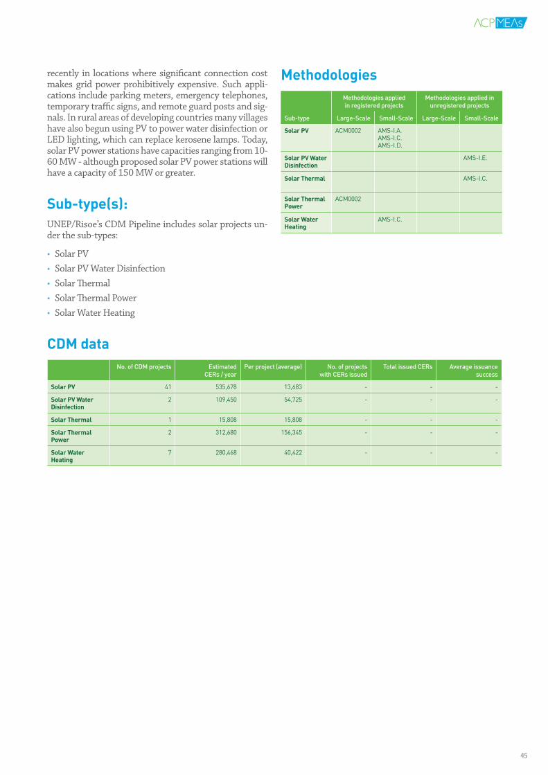
recently in locations where significant connection cost makes grid power prohibitively expensive. Such appli-cations include parking meters, emergency telephones, temporary traffic signs, and remote guard posts and sig-nals. In rural areas of developing countries many villages have also begun using PV to power water disinfection or LED lighting, which can replace kerosene lamps. Today, solar PV power stations have capacities ranging from 10-60 MW - although proposed solar PV power stations will have a capacity of 150 MW or greater.
Sub-type(s):UNEP/Risoe’s CDM Pipeline includes solar projects un-der the sub-types:
• Solar PV• Solar PV Water Disinfection• Solar Thermal• Solar Thermal Power• Solar Water Heating
MethodologiesMethodologies applied in registered projects
Methodologies applied in unregistered projects
Sub-type Large-Scale Small-Scale Large-Scale Small-Scale
SolarPV ACM0002 AMS-I.A.AMS-I.C.AMS-I.D.
SolarPVWaterDisinfection
AMS-I.E.
SolarThermal AMS-I.C.
SolarThermalPower
ACM0002
SolarWaterHeating
AMS-I.C.
CDMdataNo. of CDM projects Estimated
CERs / yearPer project (average) No. of projects
with CERs issuedTotal issued CERs Average issuance
success
SolarPV 41 535,678 13,683 - - -
SolarPVWaterDisinfection
2 109,450 54,725 - - -
SolarThermal 1 15,808 15,808 - - -
SolarThermalPower
2 312,680 156,345 - - -
SolarWaterHeating
7 280,468 40,422 - - -
45
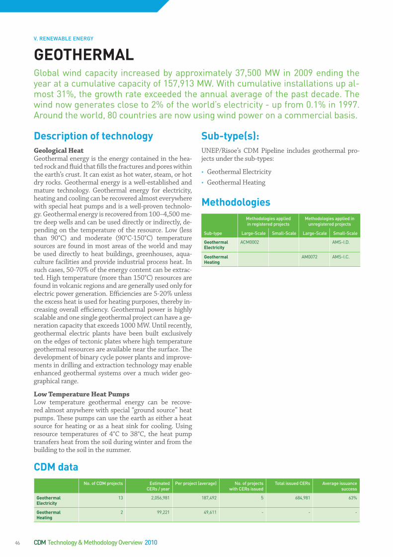
DescriptionoftechnologyGeological HeatGeothermal energy is the energy contained in the hea-ted rock and fluid that fills the fractures and pores within the earth’s crust. It can exist as hot water, steam, or hot dry rocks. Geothermal energy is a well-established and mature technology. Geothermal energy for electricity, heating and cooling can be recovered almost everywhere with special heat pumps and is a well-proven technolo-gy. Geothermal energy is recovered from 100–4,500 me-tre deep wells and can be used directly or indirectly, de-pending on the temperature of the resource. Low (less than 90°C) and moderate (90°C-150°C) temperature sources are found in most areas of the world and may be used directly to heat buildings, greenhouses, aqua-culture facilities and provide industrial process heat. In such cases, 50-70% of the energy content can be extrac-ted. High temperature (more than 150°C) resources are found in volcanic regions and are generally used only for electric power generation. Efficiencies are 5-20% unless the excess heat is used for heating purposes, thereby in-creasing overall efficiency. Geothermal power is highly scalable and one single geothermal project can have a ge-neration capacity that exceeds 1000 MW. Until recently, geothermal electric plants have been built exclusively on the edges of tectonic plates where high temperature geothermal resources are available near the surface. The development of binary cycle power plants and improve-ments in drilling and extraction technology may enable enhanced geothermal systems over a much wider geo-graphical range.
Low Temperature Heat PumpsLow temperature geothermal energy can be recove-red almost anywhere with special “ground source” heat pumps. These pumps can use the earth as either a heat source for heating or as a heat sink for cooling. Using resource temperatures of 4°C to 38°C, the heat pump transfers heat from the soil during winter and from the building to the soil in the summer.
Sub-type(s):UNEP/Risoe’s CDM Pipeline includes geothermal pro-jects under the sub-types:
• Geothermal Electricity• Geothermal Heating
MethodologiesMethodologies applied in registered projects
Methodologies applied in unregistered projects
Sub-type Large-Scale Small-Scale Large-Scale Small-Scale
GeothermalElectricity
ACM0002 AMS-I.D.
GeothermalHeating
AM0072 AMS-I.C.
GEOTHERMALGlobal wind capacity increased by approximately 37,500 MW in 2009 ending the year at a cumulative capacity of 157,913 MW. With cumulative installations up al-most 31%, the growth rate exceeded the annual average of the past decade. The wind now generates close to 2% of the world’s electricity - up from 0.1% in 1997. Around the world, 80 countries are now using wind power on a commercial basis.
CDMdataNo. of CDM projects Estimated
CERs / yearPer project (average) No. of projects
with CERs issuedTotal issued CERs Average issuance
success
GeothermalElectricity
13 2,056,981 187,492 5 684,981 63%
GeothermalHeating
2 99,221 49,611 - - -
V. RENEWABLE ENERGY
CDM Technology & Methodology Overview 201046
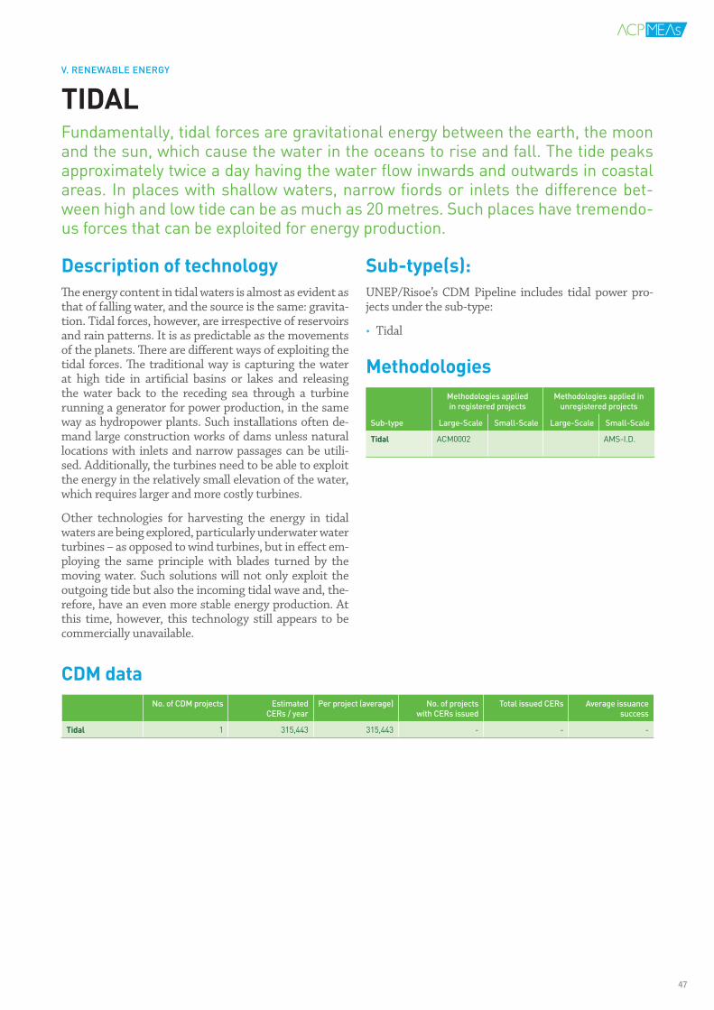
DescriptionoftechnologyThe energy content in tidal waters is almost as evident as that of falling water, and the source is the same: gravita-tion. Tidal forces, however, are irrespective of reservoirs and rain patterns. It is as predictable as the movements of the planets. There are different ways of exploiting the tidal forces. The traditional way is capturing the water at high tide in artificial basins or lakes and releasing the water back to the receding sea through a turbine running a generator for power production, in the same way as hydropower plants. Such installations often de-mand large construction works of dams unless natural locations with inlets and narrow passages can be utili-sed. Additionally, the turbines need to be able to exploit the energy in the relatively small elevation of the water, which requires larger and more costly turbines.
Other technologies for harvesting the energy in tidal waters are being explored, particularly underwater water turbines – as opposed to wind turbines, but in effect em-ploying the same principle with blades turned by the moving water. Such solutions will not only exploit the outgoing tide but also the incoming tidal wave and, the-refore, have an even more stable energy production. At this time, however, this technology still appears to be commercially unavailable.
Sub-type(s):UNEP/Risoe’s CDM Pipeline includes tidal power pro-jects under the sub-type:
• Tidal
MethodologiesMethodologies applied in registered projects
Methodologies applied in unregistered projects
Sub-type Large-Scale Small-Scale Large-Scale Small-Scale
Tidal ACM0002 AMS-I.D.
TIDALFundamentally, tidal forces are gravitational energy between the earth, the moon and the sun, which cause the water in the oceans to rise and fall. The tide peaks approximately twice a day having the water flow inwards and outwards in coastal areas. In places with shallow waters, narrow fiords or inlets the difference bet-ween high and low tide can be as much as 20 metres. Such places have tremendo-us forces that can be exploited for energy production.
CDMdataNo. of CDM projects Estimated
CERs / yearPer project (average) No. of projects
with CERs issuedTotal issued CERs Average issuance
success
Tidal 1 315,443 315,443 - - -
V. RENEWABLE ENERGY
47

VI.POWERCONSUMPTIONIt is debatable whether it is the production or consumption of energy that is the cause of greenhouse gas emissions. It is not debatable, however, that saving energy is a source of potentially significant emissions reduction. Buildings, ove-rall, are a significant source of energy consumption. Approximately a third of glo-bal energy consumption is in buildings, making them an obvious target for re-duction of demand and, therefore, also carbon emissions. Today, it is possible to construct zero-energy houses, meaning houses that do not consume external energy but generate their own.
Outside of buildings, the public sector is responsible for a number of energy con-suming services where there may be significant potentials for reducing power consumption, such as street lighting, traffic lights, water pumping and was-tewater treatment.
Linking production and consumption of electricity through electricity distribu-tion systems is also a target for potential savings, as operational losses are often caused by outdated equipment or low voltage transmission. Where there are no transmission grids at all, unconnected rural villages typically operate an isolated grid or even individual power production with diesel generators. Rural electrifi-cation projects may replace emission intensive diesel power with less emission intensive power from the grid.
CDM projects are applicable to the following power consuming sectors of the economy:
• Buildings• Electricity for Grid• Public Services• Various Household Installations
CeltinsandCematgridconnectionofisolatedsystemsRef. no. 1067
The purpose of the project activity is the expansion of the Bra-zilian interconnected grid to isolated systems in the Brazilian states of Mato Grosso and Tocantins. The chosen methodology applicable here concerns the grid connection of isolated sys-tems, as is the case of the Grupo Rede CDM Project. In this case, several isolated “mini-grids” (off-grid power generation) operating in communities in the states of Mato Grosso and To-cantins (midwest and north Brazil) are being connected to the national grid. All fossil fuel fired power plants in the isolated systems are displaced, while renewable energy based electrici-ty generation in the respective isolated systems is not signifi-cantly affected. Historical data on power generation and fuel consumption in the isolated systems is available to accurately estimate the most likely scenario in the absence of the pro-ject activity.
Project investment: USD 1,800,000
Project CO2 reduction over a crediting period of 7 years:
382,211 tCO2e
Expected CER revenue (CER/USD 10): USD 3,822,110
48

DescriptionoftechnologyEnergy Efficiency in BuildingsEnergy efficiency investments in buildings can have re-latively short payback times depending on the present level of efficiency and prices of energy. New zero-ener-gy buildings employ a range of technologies including power/heat generation and may have longer payback ti-mes. The most commonly known and adopted techno-logy to reduce power and energy consumption in buil-dings is insulation of walls and installation of double or triple glazing in windows - with or without special gases for improved insulation capabilities. Today, windows are manufactured that are just as efficient as walls in terms of insulation effect. Insulation is equally efficient for keeping buildings warm and cold. Therefore, insulation is not only for cold climates - in fact, it is even more effi-cient for warm climates as cooling takes up approxima-tely three times as much energy as warming.
AppliancesIn that respect air conditioning is the single most impor-tant power consumer in buildings. It is an area where sig-nificant amounts of power can be saved, either by insta-lling more efficient air-conditioners and/or by extracting cooling and/or heating from ventilation air in buildings through heat exchangers. Other electrical appliances em-ployed in buildings may also be more or less energy effi-cient. Through labeling programmes consumers may be led to choose the more efficient appliances. Standards for such labeling are already well-implemented in many countries. Water pumping in houses and buildings also consumes energy and can be the target for pump repla-cement programmes. The most efficient pumps may consume as little as 20% of that of a traditional pump.
LightingLighting is an obvious source of potential power savings. Exchanging incandescent bulbs with CFL low energy bulbs reduces power consumption by 70-80% and pro-grammes have been initiated, also in rural areas, whe-re exchange of bulbs is financed by the energy savings alone.
Sub-type(s):UNEP/Risoe’s CDM Pipeline includes power consump-tion projects under the sub-types:
• Air Conditioning • EE New Buildings• Lighting • EE Public Buildings • EE Shops • HVAC & Lighting• Appliances
BUILDINGSBuildings, overall, are a significant source of energy consumption. Approximately a third of global energy consumption is in buildings, making them an obvious tar-get for reduction of demand and, therefore, also carbon emissions. Many diffe-rent technologies are employed in buildings: heating, cooling, lighting, electrical appliances and internal transportation (elevators, escalators). Today, it is possible to construct zero-energy houses, meaning houses that no longer consume exter-nal energy but generate their own.
VI. POWER CONSUMPTION
49

CDMdataNo. of CDM projects Estimated
CERs / yearPer project (average) No. of projects
with CERs issuedTotal issued CERs Average issuance
success
AirConditioning 0 - - - - -
EnergyEfficiency–NewBuildings
4 49,822 12,678 1 6,521 63%
Lighting 30 1,510,311 50,331 - - -
EnergyEfficiency–PublicBuildings
4 67,892 17,367 - - -
EnergyEfficiency–CommercialBuildings
1 10,834 10,834 - - -
Appliances 0 - - - - -
MethodologiesMethodologies applied in registered projects
Methodologies applied in unregistered projects
Sub-type Large-Scale Small-Scale Large-Scale Small-Scale
AirConditioning
AMS-II.E.
EnergyEfficiency–NewBuildings
AMS-II.B.AMS-II.E
Lighting AMS-II.C.AMS-II.J.
AM0046 AMS-I.A.
EnergyEfficiency–PublicBuildings
AMS-I.C.AMS-II.E.AMS-III.B.
AMS-I.D.
EnergyEfficiency–CommercialBuildings
ACM0002 AMS-I.D.AMS-II.E.
Appliances AMS-III.X.
CDM Technology & Methodology Overview 201050

DescriptionoftechnologyConnection of Isolated GridRemote rural areas are often without access to the elec-tricity grid. Commonly, they depend on isolated grids or individual installations with generators typically fuelled by diesel. Expansion of an interconnected electricity grid to such isolated systems displaces the often inefficient and emission intensive diesel power generation by more efficient, less carbon intensive power generation from the connected grid. At the same time rural electrifica-tion, in combination with proper financial engineering, promises environmentally friendly access to electrici-ty at a lower cost. One example could be a small hydro-power acting as an isolated power generation systems. Use of such installations refers to the lower limit of mi-cro applications.
Efficient Electricity DistributionIn existing electricity grids measures can be taken that reduce technical energy losses. Normally, losses are rela-tively higher the lower the voltage. Options include up-grading the voltage of a transmission and distribution system and replacing existing transformers with more efficient ones.
Sub-type(s):UNEP/Risoe’s CDM Pipeline includes electricity grid re-lated projects under the sub-types:
• Connection of Isolated Grid • Efficient Electricity Distribution
MethodologiesMethodologies applied in registered projects
Methodologies applied in unregistered projects
Sub-type Large-Scale Small-Scale Large-Scale Small-Scale
ConnectionofIsolatedGrid
AM0045 ACM0002 AMS-III.B.
EfficientElectricityDistribution
AMS-II.A.
ELECTRICITYGRIDIn existing electricity distribution systems operational losses are often caused by outdated equipment. Losses can be reduced by replacing old transformers or by increasing the voltage in transmission lines. In some developing countries the rate of electrification in rural areas is very low, in some cases below 5%. Unconnected villages have limited access to electricity, but may have isolated systems, typically a diesel generator. In this case, rural electrification projects replace emission in-tensive diesel power with less emission intensive power from the grid, resulting in emissions reduction.
CDMdataNo. of CDM projects Estimated
CERs / yearPer project (average) No. of projects
with CERs issuedTotal issued CERs Average issuance
success
ConnectionofIsolatedGrid
1 54,602 54,602 - - -
EfficientElectricityDistribution
4 122,943 31,092 - - -
VI. POWER CONSUMPTION
51
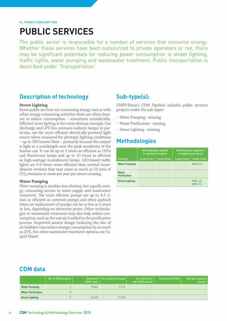
DescriptionoftechnologyStreet Lighting Some public services are consuming energy and as with other energy consuming activities there are often chan-ces to reduce consumption – sometimes considerably. Efficient street lighting is the most obvious example. Gas discharge and LPS (low pressure sodium) lamps, in par-ticular, are the most efficient electrically-powered light source when measured for photopic lighting conditions – up to 200 lumen/Watt – primarily because the output is light at a wavelength near the peak sensitivity of the human eye. It can be up to 2 times as efficient as LEDs and fluorescent lamps and up to 10 times as efficient as high-wattage incandescent lamps. LED-based traffic lights are 5-6 times more efficient than normal incan-descent versions that may cause as much as 10 tons of CO2 emission or more per year per street crossing.
Water PumpingWater pumping is another less obvious, but equally ener-gy consuming service in water supply and wastewater treatment. The most efficient pumps are up to 4-5 ti-mes as efficient as common pumps and often payback times on replacement of pumps can be as low as 5 years or less, depending on electricity prices. Other technolo-gies in wastewater treatment may also help reduce con-sumption, such as the way air is added to the purification process. Improved aerator design (reducing the size of air bubbles) may reduce energy consumption by as much as 25%. For other wastewater treatment options, see ‘Li-quid Waste’.
Sub-type(s):UNEP/Risoe’s CDM Pipeline includes public services projects under the sub-types:
• Water Pumping - missing• Water Purification - missing• Street Lighting - missing
MethodologiesMethodologies applied in registered projects
Methodologies applied in unregistered projects
Sub-type Large-Scale Small-Scale Large-Scale Small-Scale
WaterPumping AMS-II.C.
WaterPurification
StreetLighting AMS-I.D.AMS-II.C.
PUBLICSERVICESThe public sector is responsible for a number of services that consume energy. Whether these services have been outsourced to private operators or not, there may be significant potentials for reducing power consumption in street lighting, traffic lights, water pumping and wastewater treatment. Public transportation is described under ‘Transportation’.
CDMdataNo. of CDM projects Estimated
CERs / yearPer project (average) No. of projects
with CERs issuedTotal issued CERs Average issuance
success
WaterPumping 2 19,824 9,912 - - -
WaterPurification 0 - - - - -
StreetLighting 2 34,533 17,752 - - -
VI. POWER CONSUMPTION
CDM Technology & Methodology Overview 201052

Energy efficiency in a household context can be divided into insulation and lighting projects; utilising household husbandry waste (manure) for methane generation and gas-based cooking, and projects based on improving the energy efficiency of cooking stoves. Insulation projects aim to improve the thermal performance of the housing units. The technology can consist of the installation of insulated ceilings, walls and floors in houses, conse-quently reducing the temperature amplitude extremes.
Lighting and AppliancesSingle energy efficient lighting projects do not contri-bute significantly to the reduction of carbon emissions. However, when packaged as part of a bigger project, they can make a significant contribution to the reduction of CO2 emissions and result in cost savings to the house-hold, as well as reduction in peak demand with all the associated electricity infrastructure savings. Lighting projects are normally replacing incandescent bulbs with CFLs (Compact Fluorescent Light) that are 4 times more efficient and last up to 10 times longer. Other options for energy saving are in efficient appliances like refrigera-tors, TVs and other household installations consuming energy. In these cases, labeling programmes help to in-crease emissions reduction potentials far beyond the single unit.
Domestic ManureOrganic wastes from animal husbandry, or domestic ma-nure, can be used in simple household installations – a biogas digester - to generate methane that can be uti-lised both for cooking and lighting. Such installations consist of a concealed hole in the ground for manure, a filter, a regulator and a gas stove. The “Programmatic” CDM approach may conceivably be able to unlock this potential for small-scale biomass projects, particularly in many lesser-developed countries.
Efficient Stoves and Solar CookingDeforestation and desertification have become a major concern in many developing countries, as wood demand for household energy largely exceeds the available re-newable woody biomass. By reducing the fuel wood con-sumption, energy efficient stoves projects help to redu-ce greenhouse gas emissions stemming from the use of non-renewable biomass. A complete replacement of the woody biomass for cooking may be achieved by introdu-cing solar cooking, where a parabolic collector focuses sun rays in a single point that provides sufficient heating for boiling purposes.
Sub-type(s):UNEP/Risoe’s CDM Pipeline includes household sys-tems under the sub-types:
• Solar Cooking• Stoves • Domestic Manure • Lighting• Lighting & Insulation & Solar – missing – har vi brug
for den? (kun ét projekt)• Appliances - missing
VARIOUSHOUSEHOLDINSTALLATIONSGlobally, households constitute an important energy consuming sector and are a significant contributor to the present 1.9 GtCO2 that are emitted worldwide every year by electric lighting. Households are also the most important source of emis-sions from cooking. Households can reduce emissions by using energy more effi-ciently. Changing normal (incandescent) light bulbs with low energy (CFL) bulbs can reduce consumption by a factor 5 for lighting. Efficient cook stoves can reduce emissions from rural households by at least 30%. Rural households may also uti-lise domestic manure from husbandry to generate biogas (methane) for cooking and lighting. Programmes for more energy efficient appliances may help reduce emissions while energy efficiency programmes for housing, including insulation and double glazing, can additionally help reduce consumption and, therefore, car-bon emissions.
Descriptionoftechnology
VI. POWER CONSUMPTION
53

CDMdataNo. of CDM projects Estimated
CERs / yearPer project (average) No. of projects
with CERs issuedTotal issued CERs Average issuance
success
SolarCooking 8 469,483 52,332 1 1,077 18%
Stoves 17 431,324 25,674 - - -
DomesticManure 17 734,312 43,821 11,761 1,761 60%
Lighting 30 1,510,311 50,331 - - -
Lighting,Insulation&Solar
1 6,580 6,580 - - -
Appliances 0 - - - - -
Visakhapatnam(India)OSRAMCFLdistributionCDMProjectRef. no. 1754
The “Visakhapatnam (India) OSRAM CFL distribution CDM Project” involves the distribution of approximately 450,000 to 500,000 OSRAM long life Compact Fluorescent Lamps (CFLs) in the district of Visakhapatnam, which numbers about 700,000 households. The CFLs used are OSRAM DU-LUX EL LONGLIFE, and have the capacity of 15,000 hours and 80% lower energy consumption than a conventional light bulb.
Project investment: USD 2,036,000
Project CO2 reduction over a crediting period of 7 years:
51,116 tCO2e
Expected CER revenue (CER/USD 10): USD 511,160
MethodologiesMethodologies applied in registered projects
Methodologies applied in unregistered projects
Sub-type Large-Scale Small-Scale Large-Scale Small-Scale
SolarCooking AMS-I.C.
Stoves AMS-I.E.AMS-II.G.
AMS-I.C.
DomesticManure
AMS-I.E.AMS-I.C.AMS-II.B.AMS-III.R.
ACM0010
Lighting AMS-II.C.AMS-II.J.
AM0046 AMS-I.A.
Lighting,Insulation&Solar
AMS-I.C.AMS-II.C.AMS-II.E.
Appliances AMS-III.X.
CDM Technology & Methodology Overview 201054

VII.INDUSTRIALPRODUCTIONPROCESSESIndustrial processes are sources of greenhouse gas emissions in many ways. First, recovery of waste energy from heavy industrial production like cement and steel has potential to reduce overall energy demand from the grid. Additiona-lly, energy efficiency options may be identified through overall energy audits and possibly implemented by energy service companies.
In some specific industries there may be more potent reduction options, like in the chemicals sector or in cement, where clinker replacement is a significant source of emissions reduction. The capturing and reusing of CO2 from industrial processes is also an option for emissions reduction.
The most obvious reduction is of certain highly polluting gases, which are used for – or are by-products of – industrial production, and have global warming po-tentials of up to 23,900 times that of CO2. These gases are currently the source of more than half of the CERs issued from CDM projects and not all options are exhausted yet.
The selection of industrial sectors in which CDM has assisted in reducing carbon emissions is diverse and comprises:
• Carbon Capture• Energy Efficiency in Industry• Industrial Waste Heat and Waste Gas• Industrial Gases• Other Industrial Processes• Coal Mining and other Mining• Oil and Gas
TaishanCementWorksWasteHeatRecoveryandUtilisationforPowerGenerationProjectRef. no. 2405
The project involves utilisation of waste heat for electricity ge-neration, on-site at a cement production facility. The recovery of the excess heat takes place at two different stages in both of the production lines, via four recovery boilers. The heat re-trieved at the two different stages, is of different temperatures. The recovery boilers responsible for the higher temperature waste heat will produce superheated steam and feed it directly to the steam turbine. In the case of the recovery boilers retrie-ving the lower temperature excess heat, the output of these will be hot pressurized water, which in turn will be fed through a flash steam generator to produce saturated steam before feeding it through the steam turbine. Exhaust gasses from the steam turbine, will be utilised for the preheating of raw ma-terials and other stages of the production line where process heat is vital. The electricity generating steam turbine has a capacity of 13.2 MW, generating 89,500 MWh annually, re-sulting in a reduction of 107,116 tonnes of CO
2 emissions per
year.
Project investment: N.A.
Project CO2 reduction over a crediting period of 7 years:
741,260 tCO2e
Expected CER revenue (CER/USD 10): USD 7,412,600
55
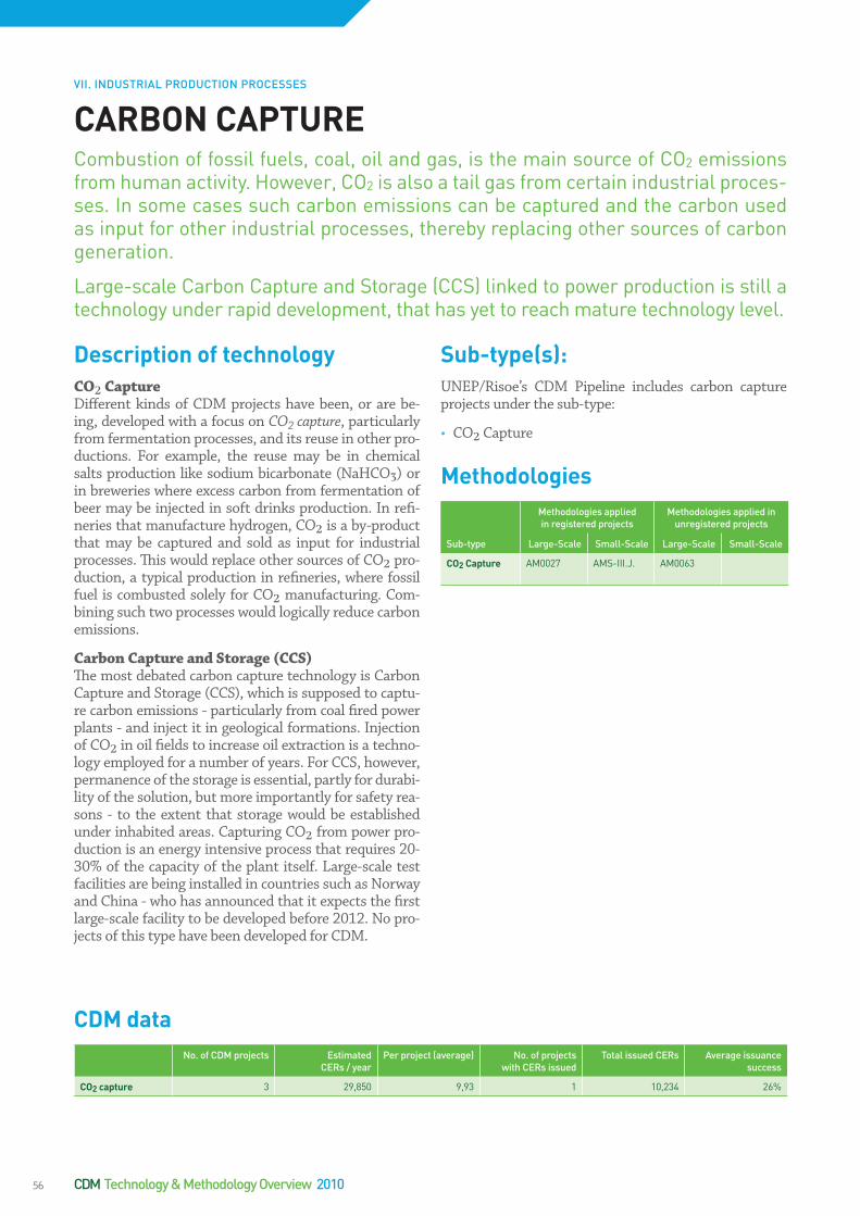
DescriptionoftechnologyCO2 CaptureDifferent kinds of CDM projects have been, or are be-ing, developed with a focus on CO2 capture, particularly from fermentation processes, and its reuse in other pro-ductions. For example, the reuse may be in chemical salts production like sodium bicarbonate (NaHCO3) or in breweries where excess carbon from fermentation of beer may be injected in soft drinks production. In refi-neries that manufacture hydrogen, CO2 is a by-product that may be captured and sold as input for industrial processes. This would replace other sources of CO2 pro-duction, a typical production in refineries, where fossil fuel is combusted solely for CO2 manufacturing. Com-bining such two processes would logically reduce carbon emissions.
Carbon Capture and Storage (CCS)The most debated carbon capture technology is Carbon Capture and Storage (CCS), which is supposed to captu-re carbon emissions - particularly from coal fired power plants - and inject it in geological formations. Injection of CO2 in oil fields to increase oil extraction is a techno-logy employed for a number of years. For CCS, however, permanence of the storage is essential, partly for durabi-lity of the solution, but more importantly for safety rea-sons - to the extent that storage would be established under inhabited areas. Capturing CO2 from power pro-duction is an energy intensive process that requires 20-30% of the capacity of the plant itself. Large-scale test facilities are being installed in countries such as Norway and China - who has announced that it expects the first large-scale facility to be developed before 2012. No pro-jects of this type have been developed for CDM.
Sub-type(s):UNEP/Risoe’s CDM Pipeline includes carbon capture projects under the sub-type:
• CO2 Capture
MethodologiesMethodologies applied in registered projects
Methodologies applied in unregistered projects
Sub-type Large-Scale Small-Scale Large-Scale Small-Scale
CO2Capture AM0027 AMS-III.J. AM0063
CARBONCAPTURECombustion of fossil fuels, coal, oil and gas, is the main source of CO2 emissions from human activity. However, CO2 is also a tail gas from certain industrial proces-ses. In some cases such carbon emissions can be captured and the carbon used as input for other industrial processes, thereby replacing other sources of carbon generation.
Large-scale Carbon Capture and Storage (CCS) linked to power production is still a technology under rapid development, that has yet to reach mature technology level.
CDMdataNo. of CDM projects Estimated
CERs / yearPer project (average) No. of projects
with CERs issuedTotal issued CERs Average issuance
success
CO2capture 3 29,850 9,93 1 10,234 26%
VII. INDUSTRIAL PRODUCTION PROCESSES
CDM Technology & Methodology Overview 201056

Most industries consume energy for activities that are not specific to their particular production. Installation of higher efficiency appliances or equipment, such as lamps, refrigerators, motors, fans, air conditioners, and pumping systems that are all auxiliary installations, can improve efficiency. Such areas of intervention can be identified through energy audits, which are increasin-gly being offered as services to industries. Applicability is commonplace with options in cement, chemicals, cons-truction, machinery, electronics, food, glass, non-ferrous metals and other metal products. In some cases energy efficiency is obtained through installation of higher effi-ciency equipment (e.g. motors and fans) and fuel switch (e.g. switching from steam or compressed air to electri-city) at different industrial or mining facilities. There are also possibilities of integrating a number of utility provi-sions in an industrial facility into one single utility, repla-cing the original installations, e.g. cogeneration through combined heat and power (CHP) or trigeneration (com-bined cooling, heat and power) – for more, see Heating Systems. Waste heat and waste gas recovery is an option in several heavy industries and is treated separately un-der Industrial Waste Heat and Waste Gas Recovery.
Alcohol, Beer and other Fermenting Industries: Capture/Reuse of CO2 Energy efficiency for industries where fermenting pro-cesses are a part of the production line can be ensured through the capturing of CO2 that would otherwise be vented into the atmosphere. The recovered CO2 is sub-sequently utilised as raw material for industrial proces-ses, such as the production of liquid CO2. Therefore, the environmental benefit from these projects is,reached by the reduction in the amount of CO2 vented into the atmosphere, as well as the displacement of the produc-tion of CO2 at dedicated facilities, thereby lowering the overall energy consumption. Projects of this type can be characterised as both CO2 capture and energy efficiency projects, as the positive benefit, in terms of decreased greenhouse gas emissions, is obtained through utilising otherwise vented CO2 as well as savings on fossil fuels for production of e.g. liquid CO2.
Paper Production - Recovery of Caustic Soda from Black Liquor For industries where caustic soda is produced as an unwanted by-product, energy efficiency can be obtai-ned through the recovery of the undesired caustic soda, from e.g. black liquor in paper production. The recovered caustic soda is transferred to conventional soda manu-facturing plants, thus, displacing the production of caus-tic soda at dedicated plants. This displacement results in overall lower energy consumption since the energy re-quired to recover the caustic soda is less than the ener-gy consumption of producing caustic soda at a dedicated plant. Consequently, the overall energy consumption is lowered and the energy efficiency improved.
The black liquor is also a potential source of biomass ba-sed energy production. To manufacture pulp for paper, cardboard etc., wood chips are boiled at high pressure and temperature to remove the lignin that holds the fi-bres together. Approximately half of the original energy content is left in the fibres in the paper, while the rest ends up in the used cooking liquor, which is called black liquor. The black liquor may either be gasified or turned into biofuel.
Iron and Steel Industry - Decreased Coke Con-sumption In iron and steel production it is possible to achieve a higher efficiency by decreasing the coke consumption in blast furnaces. This is done by feeding reduced iron pellets directly into the blast furnace. These pellets are produced by a dust/sludge-recycling system that needs to be established in connection with the production line. The energy efficiency is achieved by the recycling of otherwise undesired by-products as a source of energy, thereby reducing the amount of fossil fuel required to produce the raw material for the steel production.
ENERGYEFFICIENCYININDUSTRYIndustrial energy efficiency holds immense potential to saving energy and costs while at the same time reducing CO2 emissions. Very often investments in energy efficien-cy have very short payback times, as costs of plant operation are reduced. As an addi-tional economic incentive such projects can often be registered as CDM projects ge-nerating CERs. Most industries can save energy through traditional means of using more energy efficient equipment. Other industries have industry specific options. A key source of energy efficiency improvement is recovery of waste heat and gas. This parti-cular technology applies to many heavy industries and is a common type of CDM pro-ject (see separate fact sheet ‘Industrial Waste Heat and Waste Gas Recovery’).
Descriptionoftechnology
VII. INDUSTRIAL PRODUCTION PROCESSES
57

Brick Production – Change of Kiln Technology, Full or Partial Fuel SwitchIn production of building materials, and particularly brick production, several measures are available in order to increase energy efficiency. This can be achieved by mo-difying the production line by 1) shifting to alternative brick production processes – typically from horizontal kilns to vertical shaft technology, 2) partially substitu-ting fossil fuels with renewable biomass (e.g. sawdust, waste products, organic liquid residues from food indus-try), or 3) completely or partially substituting high car-bon intensive fuels with low carbon intensive fuels. Whi-le change of fuels may be straight forward (see fact sheet on fuel switch), introduction of vertical shaft kilns requi-re reconstruction of the kiln itself. Doing so entails signi-ficant fuel savings by utilising the heat from already bur-nt bricks to pre-heat the kiln. Another possibility is to alter the brick manufacturing process in order for it not to include sintering of the produced clay bricks, thereby eliminating the use of fossil fuels for this energy intensi-ve part of the production.
Sub-type(s):UNEP/Risoe’s CDM Pipeline includes projects concer-ning energy efficiency in industry under the sub-types:
• Black Liquor• Paper• Chemicals• Cement• Iron & Steel• Machinery • Textiles • Electronics• Food• Building Materials• Glass• Non-Ferrous Metals • Coke Oven• Construction• Metal Products
MethodologiesMethodologies applied in registered projects
Methodologies applied in unregistered projects
Sub-type Large-Scale Small-Scale Large-Scale Small-Scale
BlackLiquor ACM0002ACM0006
AMS-I.C. ACM0012 AMS-III.H.
Paper AM0018 AMS-I.D.AMS-II.D.
ACM0002ACM0006ACM0012
AMS-I.C.AMS-II.C.AMS-II.H.AMS-III.H.AMS-III.M.
Chemicals AM0018 AMS-I.D.AMS-II.C.AMS-II.D.AMS-III.D.
AMS-I.C.AMS-II.B.AMS-III.B.AMS-III.Q.AMS-II.H.
Petrochemicals ACM0004AM0018
AMS-II.D.AMS-III.P.
AM0044 AMS-II.B.AMS-III.D.AMS-II.C.AMS-II.H.
Cement AMS-I.D.AMS-II.D.
AMS-III.B.AMS-II.C.AMS-II.H.
Iron&Steel AMS-II.D. AM0066 AMS-I.D.AMS-III.Q.AMS-II.C.AMS-II.H.
Machinery AMS-II.C. AMS-II.D.AMS-II.H.
Textiles AMS-II.C.AMS-II.D.
AM0014 AMS-II.H.AMS-II.B.AMS-III.Q.
Electronics AMS-II.D. AMS-II.C.AMS-II.H.
Food AMS-I.C.AMS-II.D.
AMS-II.C.AMS-II.H.AMS-II.E.
BuildingMaterials
AMS-II.D.AMS-III.AD
AMS-II.C.AMS-II.H.AMS-II.G.AMS-III.Z.
Glass AMS-II.D. AMS-I.D.AMS-II.C.AMS-II.H.
Non-FerrousMetals
AM0038 AM0059 AMS-II.B.AMS-II.C.AMS-II.D.AMS-II.H.
CokeOven AMS-II.C.AMS-II.D.AMS-II.H.AMS-III.V.
Construction(noprojectsyet)
AMS-II.C.AMS-II.D.AMS-II.H.
MetalProducts AMS-II.D.AMS-II.C.AMS-II.H.
CDM Technology & Methodology Overview 201058

CDMdataNo. of CDM projects Estimated
CERs / yearPer project (average) No. of projects
with CERs issuedTotal issued CERs Average issuance
success
BlackLiquor 11 1,390,329 126,463 1 186,398 297%
Paper 14 455,432 33,839 5 303,872 91%
Chemicals 27 877,829 32,492 6 167,829 83%
Petrochemicals 24 781,289 33,872 6 330,899 82%
Cement 14 204,803 16,828 2 26,429 101%
Iron&Steel 11 276,822 25,321 - - -
Machinery 7 238,390 34,292 - - -
Textiles 8 178,872 22,288 1 51,382 195%
Electronics 3 43,982 14,322 - - -
Food 4 31,231 8,329 1 2,168 66%
BuildingMaterials 16 581,231 36,432 2 37,654 65%
Glass 2 20,430 10,219 1 41,087 91%
Non-ferrousMetals 4 877,382 219,322 1 335,321 143%
CokeOven 1 59,983 59,983 - - -
Construction 0 - - - - -
MetalProducts 0 - - - - -
59

Waste Heat RecoveryExcess heat from production of cement, iron and ste-el, non-ferrous metals, building materials, glass, chemicals or petrochemicals can be in both the form of hot water or hot gas (non-flammable). To benefit from the ex-cess heat it is necessary to recover and typically feed it to a steam turbine. Before the actual electricity genera-tion, the waste energy carrying medium – water or gas – is routed through a boiler system where superheated steam is generated. Less commonly, mechanical ener-gy - in the form of high-pressure gas or liquid - is utili-sed at the production facility. Additionally, excess heat can always be recovered with the purpose of utilising it as process heat, thereby reducing energy consumption. For projects generating electricity, the reduction of GHG emissions is achieved by the displacement of electricity supplied from the local grid or by replacing already exis-ting generators at the plant, typically diesel generators. There are a number of industries in which this type of project is relevant. Particularly the cement, iron and ste-el industries have utilised the CDM to support the es-tablishment of waste heat recovery projects. The chemi-cals industry also has a number of projects while only a few projects in other energy intensive industries such as glass making and building materials industries, have been recorded..
Waste Gas RecoveryIf the waste energy carrying medium is a flammable gas, the energy can be utilised through direct combustion. This is frequently seen in CDM projects at petrochemical industries (e.g. refineries) as well as in coke ovens and in the carbon black industry, where pure elemental carbon, in the form of colloidal particles, are produced by incom-plete combustion or thermal decomposition of gaseous or liquid hydrocarbons under controlled conditions. Of-ten, the waste gas of this type of project is identical to the so-called refinery gas or still gas, but is nevertheless considered waste gas, as the pressure is low and difficult to utilise. For own generation projects the waste gas is incinerated to supply process heat used at the produc-tion site, thereby reducing dependency on fossil fuels. Alternatively, if the practice is to vent the waste gas into the atmosphere, a simple flaring will turn a high content of methane (CH4) into CO2. This reduces GHG conside-rably due to the relatively higher global warming poten-tial of methane.
Often waste heat and gas recovery projects are very pro-fitable with a payback time of as little as 3-4 years. This has caused problems in proving project additionality un-der CDM and many projects have been rejected on tho-se grounds.
INDUSTRIALWASTEHEATANDWASTEGASOne way of meeting the challenges of reducing GHG emissions is to implement ener-gy efficiency in industries. Many industries generate large amounts of waste heat and gas which may be utilised for power generation or steam, to be used either at the facility itself as captive power production or exported to neighbouring industries or the public electricity grid. Such projects generate emissions reduction by repla-cing other sources of energy production, typically from fossil fuels.
Descriptionoftechnology
VII. INDUSTRIAL PRODUCTION PROCESSES
CDM Technology & Methodology Overview 201060
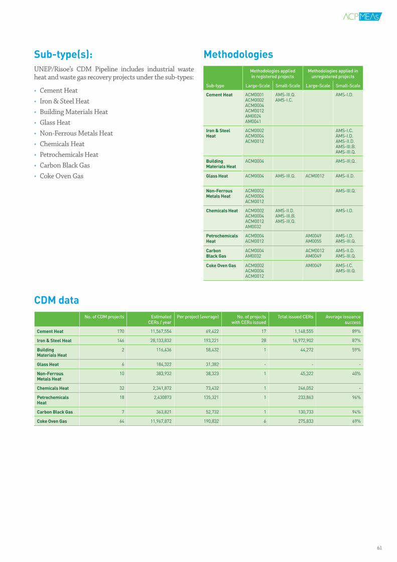
CDMdataNo. of CDM projects Estimated
CERs / yearPer project (average) No. of projects
with CERs issuedTotal issued CERs Average issuance
success
CementHeat 170 11,567,554 69,422 17 1,148,555 89%
Iron&SteelHeat 146 28,133,832 193,221 28 16,972,902 87%
BuildingMaterialsHeat
2 116,436 58,432 1 44,272 59%
GlassHeat 6 184,322 31,382 - - -
Non-FerrousMetalsHeat
10 383,932 38,323 1 45,322 40%
ChemicalsHeat 32 2,341,872 73,432 1 246,052 -
PetrochemicalsHeat
18 2,430873 135,321 1 233,863 96%
CarbonBlackGas 7 363,821 52,732 1 130,733 94%
CokeOvenGas 64 11,967,872 190,832 6 275,833 69%
Sub-type(s):UNEP/Risoe’s CDM Pipeline includes industrial waste heat and waste gas recovery projects under the sub-types:
• Cement Heat • Iron & Steel Heat• Building Materials Heat • Glass Heat • Non-Ferrous Metals Heat • Chemicals Heat• Petrochemicals Heat• Carbon Black Gas • Coke Oven Gas
MethodologiesMethodologies applied in registered projects
Methodologies applied in unregistered projects
Sub-type Large-Scale Small-Scale Large-Scale Small-Scale
CementHeat ACM0001ACM0002ACM0004ACM0012AM0024AM0041
AMS-III.Q.AMS-I.C.
AMS-I.D.
Iron&SteelHeat
ACM0002ACM0004ACM0012
AMS-I.C.AMS-I.D.AMS-II.D.AMS-III.B.AMS-III.Q.
BuildingMaterialsHeat
ACM0004 AMS-III.Q.
GlassHeat ACM0004 AMS-III.Q. ACM0012 AMS-II.D.
Non-FerrousMetalsHeat
ACM0002ACM0004ACM0012
AMS-III.Q.
ChemicalsHeat ACM0002ACM0004ACM0012AM0032
AMS-II.D.AMS-III.B.AMS-III.Q.
AMS-I.D.
PetrochemicalsHeat
ACM0004ACM0012
AM0049AM0055
AMS-I.D.AMS-III.Q.
CarbonBlackGas
ACM0004AM0032
ACM0012AM0049
AMS-II.D.AMS-III.Q.
CokeOvenGas ACM0002ACM0004ACM0012
AM0049 AMS-I.C.AMS-III.Q.
61

N2ONitrous oxide is a waste gas from the production of se-veral chemical components, such as nitric acid, adipic acid and caprolactam. Nitric acid is used for production of fer-tilizers, explosives and the etching and dissolution of me-tals. Both adipic acid and caprolactam are used for nylon production. Although several steps can be taken at va-rious stages of production to reduce or remove nitrous oxide, only the catalytic decomposition or catalytic re-duction of N2O is relevant within the framework of CDM projects. In this process the unwanted nitrous oxide is co-llected at the end of the production line, where it has to be collected at the earliest point possible for it to main-tain the highest possible temperature (approximately 500-550°C) to facilitate a catalytic decomposition. Addi-tional heating may be necessary. Installation of a tail gas turbine may facilitate electricity generation thereby re-trieving some of the energy that may have been used for additional heating. The process will not interfere with the production of nitric acid, adipic acid or caprolactam and does not affect the productivity of the production facility.
SF6SF6 is used for its unique chemical properties as a cover gas in different industrial processes. In magnesium pro-duction SF6 is used as cover gas due to the volatility of the metal, which easily reacts with other materials, as well as air. In such cases, it may be replaced by another cover gas. One of these alternatives is in fact HFC134a. Although HFC134a is also a potent GHG (see above) it is, nevertheless, a substantial improvement over SF6. In high-voltage electrical components (transformer and switches in substations for electrical grids) SF6 is used for insulation. In this production the SF6 may be reco-vered and recycled. In the production of LCD displays SF6 is used as an etching gas. For projects where SF6 is used as an etching gas the option of thermal destruction at temperatures of approximately 1300-1400°C is usua-lly chosen. Approximately 80% of the global emission of SF6 originates from the use of the gas as insulation for high-voltage electrical equipment.
HFC-23There are very few, if any, options left for incinerating HFC-23. Being highly profitable, all possibilities seem to have been exhausted. Further, the Executive Board for CDM has prohibited registration of HFC-23 projects and now only allows projects at existing production facilities having been in operation for at least three years, bet-ween 2000 and 2004, that have had continuous produc-tion since 2005. This eliminates the possibility of CDM projects on newly constructed plants. HFC-23 is an un-desired by-product from the production of HCFC-22, a fluoric refrigerant. Contrariwise, options for destructing HFC-134a have rarely been utilised. HFC-134a is used as a blowing agent during production of polyurethane foam, e.g. for different types of insulated panels. HFC-134a may be replaced by other blowing agents like pen-tane, an ignitable blowing agent with no GWP. Since the agent is ignitable, precautionary safety measures must be taken to ensure a safe production, but the technology is well established.
PFCPFC emissions happen when a sudden increase in vol-tage and corresponding decrease in amperage happen in the electrolysis in an aluminum smelter. The sudden increase can be quenched by tilting the anode system which is normally done manually, but in the case of pro-jects qualifying for CDM registration, this is done by im-plementing different algorithms for better control of the smelting process. The algorithm detects early stages of voltage build-up based on specific patterns occurring in the pot prior to the increase.
INDUSTRIALGASESCertain gases, which are used for – or are by-products of – industrial production, have a large global warming potential (GWP). These gases include: nitrous oxide (N2O), known as laughing gas (GWP: 310), released in production of adipic and nitric acids, HFC-134a and HFC-23 (GWP: 1300 and 11,700 respectively), which are by-products from production of refrigerants, the PFCs (mainly CF4 and C2F6; GWP 6500 and 9200 respectively) released in the aluminum industry, and SF6, the most powerful green-house gas used in power substations and LCD screen production (GWP of 23,900). To compare, the GWP of CO2 is 1. There are obvious and significant GHG emission reduction potentials in reducing the emissions of these industrial gases. Currently, they are the source of more than half of the CERs issued from CDM projects.
Descriptionoftechnology
VII. INDUSTRIAL PRODUCTION PROCESSES
CDM Technology & Methodology Overview 201062

Sub-type(s):UNEP/Risoe’s CDM Pipeline includes industrial gases projects under the sub-types:
• Adipic Acid• Nitric Acid • Caprolactam (N2O) • HFC23 • HFC134a • PFCs• SF6
MethodologiesMethodologies applied in registered projects
Methodologies applied in unregistered projects
Sub-type Large-Scale Small-Scale Large-Scale Small-Scale
AdipicAcid AM0021
NitricAcid AM0028AM0034
Caprolactam(N20)
AM0028
HFC23 AM0001
HFC134a AMS-III.N.
PFCs AM0030AM0059
SF6 AM0065AM0078
AM0035AM0079
CDMdataNo. of CDM projects Estimated
CERs / yearPer project (average) No. of projects
with CERs issuedTotal issued CERs Average issuance
success
AdipicAcid 4 29,176,822 7,294,372 4 161,441,322 125%
NitricAcid 64 19,853,832 310,933 17 14,811,281 99%
Caprolactam(N20) 3 971,821 324,276 - - -
HFC23 19 81,650,832 4,297,982 18 218,637,632 105%
HFC134a 3 64,843 21,232 - - -
PFCs 6 685,432 114,322 - - -
SF6 12 4,477,833 373,831 - - -
CarbonBlackGas 7 363,332 52,382 1 130,432 94%
CokeOvenGas 64 11,967,872 190,832 6 275,833 69%
63

Clinker Replacement in Cement ProductionThe cement industry is responsible for approximately 5% of global man-made CO2 emissions - 50% comes from the chemical process and 40% from burning fuel. For every 1000 kg of cement produced, there is nearly 900 kg of CO2 emitted. Cement is made by heating limestone with small quantities of other materials at high tempe-ratures in a kiln, in a process known as calcination. The resulting hard substance, called ‘clinker’, grounded with gypsum, makes the Ordinary Portland Cement (OPC). Clinker manufacturing is an energy intensive process.
To reduce emissions one option is to limit the percenta-ge of clinker in the final cement product or using non-carbonated calcium sources by blending the cement with other materials like fly ash, pozzolana or slag. This blending reduces thermal energy and electricity require-ments in pre-processing and pyro-processing of cement manufacturing. Fly ash is typically filtered from coal-fi-red power plant exhausts. Alternatively, volcanic ash may be used. Pozzolana can come from incineration of rice husks, which leaves approximately 20% of the rice husk weight as ash.
Use of non-carbonated calcium sources requires a dry pre-calcination cement clinker production line. This is done by using calcium carbide residue (CCR) to displace limestone as raw materials, while employing the technology of wet-grinding and dry-burning process (WDP) clinker produc-tion. CCR is a non-carbonated calcium source in the raw mix for clinker processing, since no decarbonisation reac-tion occurs. This more than compensates for the slightly greater energy consumption compared to limestone de-carbonisation that emits considerable amounts of CO2. Up to now, the cement industry did not show its full CDM potential due to difficulties in applying the methodolo-gies, finding sufficient quantities of other raw materials and demonstrating additionality.
Recovery of Caustic Soda in Chemical ProductionIn various chemicals industries it is possible to recover sulphuric acid or caustic soda. Among these are produc-tion of dyes, pigments and drugs. The similarity among these industrial production lines is that operations like nitration, cyclisation or pigment formation is part of the production process. The reduction of GHG emissions is ensured through neutralization of spent acid with hydra-ted lime or limestone, thereby eliminating the associa-ted CO2 emissions. Apart from reducing CO2 emissions through neutralization of spent sulphuric acid, electrici-ty and/or steam is produced in the process.
Capture and Reuse of CO2 in Refineries and Fer-menting Industries Different kinds of CDM projects have been, or are being, developed with a focus on CO2 capture, particularly from fermentation processes, and reusing it in other produc-tions. The reuse may be in chemical salts production like sodium bicarbonate (NaHCO3) or in breweries where ex-cess carbon from fermentation of beer may be injected in soft drinks production. In refineries that manufacture hydrogen, CO2 is a by-product that may be captured and sold as input for industrial processes. This would replace other sources of CO2 production, a typical production in refineries, where fossil fuel is combusted solely for CO2 manufacturing. Combining such two processes would lo-gically reduce carbon emissions.
OTHERINDUSTRIALPROCESSESIn certain industries the processes involved are the cause of greenhouse gas emis-sions, typically CO2. By using different processes or technologies replacing equip-ment or raw materials, such processes may be altered. This is particularly relevant in cement production, where clinker may be replaced, and in the chemicals industry. In some cases CO2 tail gas can be captured and the carbon used as input for other industrial processes thereby replacing other sources of carbon generation.
Descriptionoftechnology
VII. INDUSTRIAL PRODUCTION PROCESSES
CDM Technology & Methodology Overview 201064

Sub-type(s):UNEP/Risoe’s CDM Pipeline includes projects concer-ning energy efficiency in industry under the sub-types:
• CO2 Capture• Chemicals• Cement• Clinker Replacement
MethodologiesMethodologies applied in registered projects
Methodologies applied in unregistered projects
Sub-type Large-Scale Small-Scale Large-Scale Small-Scale
CO2Capture AM0027 AMS-III.J. AM0063
Chemicals AM0018 AMS-I.D.AMS-II.C.AMS-II.D.AMS-III.D.
AMS-I.C.AMS-II.B.AMS-III.A.AMS-III.B.AMS-III.M.AMS-III.Q.
Cement&ClinkerReplacement
ACM0005AM0033
AMS-I.D.AMS-II.D.
ACM0003ACM0015AM0040
AMS-III.B.AMS-II.C.AMS-II.H.AMS-III.Q.
CDMdataNo. of CDM projects Estimated
CERs / yearPer project (average) No. of projects
with CERs issuedTotal issued CERs Average issuance
success
CO2capture 3 29,850 9,93 1 10,234 26%
Chemicals 27 877,829 32,492 6 167,829 83%
Cement&Clinkerreplacement
50 6,596,382 137,242 10 1,350,332 80%
65

Coal Mine and Ventilation Air MethaneMore than 90% of fugitive CH4 emissions from the coal sector come from underground coal mining. Initiatives aiming to reduce emissions from these sources are espe-cially important, although emissions from other sources, such as coal bed methane extraction sites (harvested as a natural gas resource), abandoned mines, open mining facilities, emissions from coal storage and transport etc., are also relevant for methane recovery projects.
Methane is an integral component of underground coal and surrounding rock strata. It escapes into the atmos-phere during coal mine operations due to lacking and/or inefficient methane drainage and ventilation sys-tems. Methane capture and utilisation technologies re-levant for applications in the coal mine industry may be broadly classified into three categories: coal mine metha-ne (CMM), coal bed methane (CBM) and ventilation air methane (VAM). In most cases, mines have implemented CH4 drainage or degasification systems in order to sus-tain a minimum level of worker safety. However, these systems are typically inefficient and inadequate not only in recovering CH4 but also in generating a sufficiently consistent volume, quality, and flow of gas for utilisation purposes. Therefore, CMM and VAM technologies in-volve new installation or improvement of existing CH4 gas drainage and recovery systems. CH4 concentrations in ventilation air are much lower than in dedicated dra-inage projects and require more advanced technology for their utilisation. In some cases projects involve the employment of both technologies. There is a variety of profitable utilisation purposes and end-use options for recovered coal mine CH4 emissions. In CDM project ac-tivities, captured coal mine methane may be utilised for electricity generation, motive power, and/or thermal energy, and may also be flared. Flaring reduces GHG emissions, as CH4 is converted to CO2 and H2 through combustion. The global warming potential of CO2 is 21 times lower than that of methane.
Coal Bed MethaneCBM refers to the extraction of methane before mining has commenced. This may also be registered as CDM ac-tivities if the linkage between methane extraction and pursuant mining can be established.
Other MiningOther non-hydrocarbon mining may equally cause emis-sion of methane, e.g. gold and diamond mining. Similar capture and utilisation or flaring, as with coal mining, may be employed in these mines as well. The mining sec-tor, in general, is also a significant consumer of energy and may introduce energy efficiency measures, e.g. for cooling.
Sub-type(s):UNEP/Risoe’s CDM Pipeline includes coal mining and other mining projects under the sub-types:
• Coal Mine Methane• Coal Bed Methane• CMM & Ventilation Air Methane • Ventilation Air Methane • Non-hydrocarbon Mining • Mining
COALMININGANDOTHERMININGExtraction and mining processes in the global coal mine industry is currently res-ponsible for approximately 8% of the total anthropogenic methane gas (CH4) emis-sions. Moreover, coal methane emissions are expected to increase 20% from 2000 to 2020. Since CH4 has a greenhouse gas warming effect 21 times higher than CO2, methane emissions from coal mines contribute significantly to climate changes. Ac-cordingly, CH4 reduction efforts in coal mines constitute a key opportunity to reduce global emissions cost efficiently, owing to low marginal abatement costs. In addition, ancillary benefits may accrue from coal mine CH4 reduction initiatives, including en-hanced mine safety, improved productivity, reduced local air pollution, and increased revenues.
Descriptionoftechnology
VII. INDUSTRIAL PRODUCTION PROCESSES
CDM Technology & Methodology Overview 201066
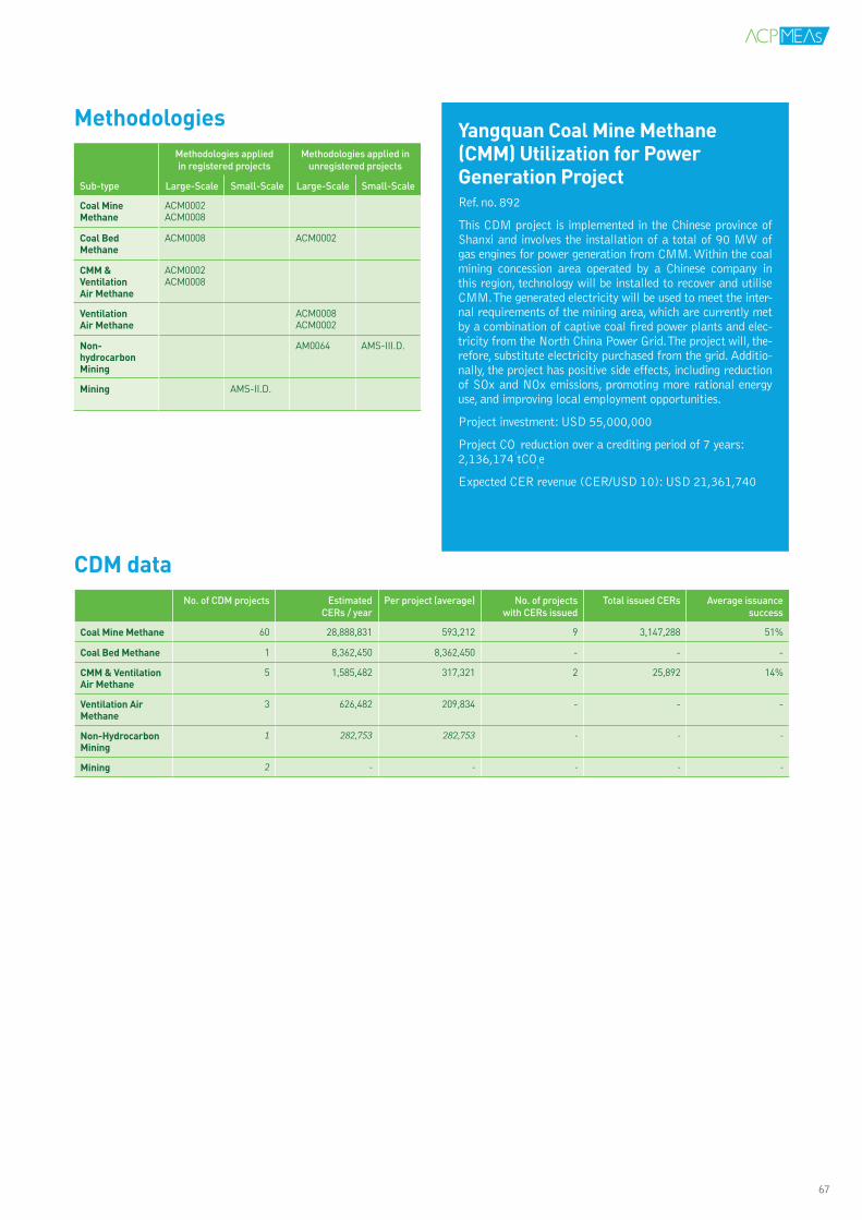
YangquanCoalMineMethane(CMM)UtilizationforPowerGenerationProjectRef. no. 892
This CDM project is implemented in the Chinese province of Shanxi and involves the installation of a total of 90 MW of gas engines for power generation from CMM. Within the coal mining concession area operated by a Chinese company in this region, technology will be installed to recover and utilise CMM. The generated electricity will be used to meet the inter-nal requirements of the mining area, which are currently met by a combination of captive coal fired power plants and elec-tricity from the North China Power Grid. The project will, the-refore, substitute electricity purchased from the grid. Additio-nally, the project has positive side effects, including reduction of SOx and NOx emissions, promoting more rational energy use, and improving local employment opportunities.
Project investment: USD 55,000,000
Project CO2 reduction over a crediting period of 7 years:
2,136,174 tCO2e
Expected CER revenue (CER/USD 10): USD 21,361,740
MethodologiesMethodologies applied in registered projects
Methodologies applied in unregistered projects
Sub-type Large-Scale Small-Scale Large-Scale Small-Scale
CoalMineMethane
ACM0002ACM0008
CoalBedMethane
ACM0008 ACM0002
CMM&VentilationAirMethane
ACM0002ACM0008
VentilationAirMethane
ACM0008ACM0002
Non-hydrocarbonMining
AM0064 AMS-III.D.
Mining AMS-II.D.
CDMdataNo. of CDM projects Estimated
CERs / yearPer project (average) No. of projects
with CERs issuedTotal issued CERs Average issuance
success
CoalMineMethane 60 28,888,831 593,212 9 3,147,288 51%
CoalBedMethane 1 8,362,450 8,362,450 - - -
CMM&VentilationAirMethane
5 1,585,482 317,321 2 25,892 14%
VentilationAirMethane
3 626,482 209,834 - - -
Non-HydrocarbonMining
1 282,753 282,753 - - -
Mining 2 - - - - -
67

RefineriesIn refineries some project activities aim at reducing oil and gas processing flaring due to leaks in pressurised equi-pment and various other unintended or irregular relea-ses of gases. The gases coming from various flare control valves, pressure valves, purge points, compressors and expanders are captured, compressed and recycled into the system, thereby eliminating the need for flaring. Other options in the petrochemicals sector concern reco-very of CO2 from flaring and utilising it as feedstock for other industrial processes, e.g. the production of liquid CO2, which is otherwise produced in a dedicated com-bustion process (often also located at the petrochemi-cals plant). Other options are to capture waste heat and gas in petrochemical installations and utilise it as pro-cess heat.
Oil and Gas ExplorationDuring exploration and exploitation of hydrocarbons, natural gas is produced along with crude oil. Those asso-ciated gases are flared due to the absence of proper eva-cuation infrastructure and the project’s remote location, with no available consumers. The flaring of those gases result in emissions of carbon dioxide (CO2) and un-com-busted methane (CH4). The rest of the gas is consumed on-site for various purposes like fuel for gas engines or process heaters. The purpose of oil field flaring reduction activities is to recover the associated gas, send it to a gas processing plant and then transport the dry gas through the pipeline to a natural gas grid. Such activities require numerous equipment and infrastructure constructions. In addition to the eventual construction of a natural gas plant and natural gas pipeline to the grid, projects invol-ve the use of gas dehydration and compression techno-logies.
PipelinesExisting natural gas pipelines are additional sources of po-tential leakage and, therefore, a target for emissions re-duction through leakage detection and repair.
Sub-type(s):UNEP/Risoe’s CDM Pipeline includes oil and gas pro-jects under the sub-types:
• Oil and Gas Processing Flaring • Oil Field Flaring Reduction • Petrochemicals• Petrochemicals Heat • Natural Gas Pipelines
OILANDGASAs oil and gas are among the largest sources of GHG emissions, there are options for reducing their contribution to global warming by introducing different practices in the sector. Flaring both in oil fields and at processing plants may be reduced or the gas can be utilised for production purposes, leakages may be reduced and fugitive gasses may be captured. The Clean Development Mechanism can provide economic incentives to alter current practices.
Descriptionoftechnology
Al-ShaheenOilFieldGasRecoveryandUtilisationProjectRef. no. 763
The purpose of the project activity is the recovery and utili-sation of associated gas produced as a by-product of oil re-covery activities at the Al-Shaheen oil field, which is operated by Maersk Oil Qatar (the “Project Developer”), in partners-hip with Qatar Petroleum. Oil recovery from the Al-Shaheen oil field (Block 5) is located about 90 kilometres off the coast of Qatar, and commenced in 1994. As part of the recent deve-lopment of the oil field, Maersk Oil Qatar has installed facili-ties for the gathering and delivery of associated gas (a blend of hydrocarbons that is released when crude oil is brought to the surface) to Qatar Petroleum’s North Field Alpha platform, and its subsequent transfer to the Mesaieed gas processing plant (GPP). Prior to 2004, associated gas at the Al-Shaheen oil field was primarily flared, with the remaining gas utilised for onsite consumption (only ~3%).
Project investment: USD 260,000,000
Project CO2 reduction over a crediting period of 10years:
17,497,540 tCO2e
Expected CER revenue (CER/USD 10): USD 1174,975,400
VII. INDUSTRIAL PRODUCTION PROCESSES
CDM Technology & Methodology Overview 201068

MethodologiesMethodologies applied in registered projects
Methodologies applied in unregistered projects
Sub-type Large-Scale Small-Scale Large-Scale Small-Scale
OilandGasProcessingFlaring
AM0037 AM0055 AMS-II.D.
OilFieldFlaringReduction
AM0009
Petrochemicals ACM0004AM0018
AMS-II.D.AMS-III.P.
AM0044 AMS-II.B.AMS-III.D.
PetrochemicalsHeat
ACM0004ACM0012
AM0049AM0055
AMS-I.D.AMS-III.Q.
NaturalGasPipelines
AM0023 AM0043 AMS-III.D.
CDMdataNo. of CDM projects Estimated
CERs / yearPer project (average) No. of projects
with CERs issuedTotal issued CERs Average issuance
success
OilandGasProcessingFlaring
4 279,422 70,625 - - -
OilFieldFlaringReduction
22 13,216,420 601,382 2 4,600,482 133%
Petrochemicals 24 781,289 33,872 6 330,899 82%
PetrochemicalsHeat
18 2,430873 135,321 1 233,863 96%
NaturalgasPipelines
9 3,862 429,632 - - -
Mining 2 59,680 29,842 1 15,025 81%
69

VIII.TRANSPORTATIONSThe transport sector is a source of significant carbon emissions. While individual transportation has yet to become a target area for emissions reduction, mass transportation systems have the potential to replace part of the individual trans-port and thereby reduce emissions. In busses, trains, metros and even in cable cars different initiatives are introduced, either for more efficient operation or for recovery of brake energy.
Shifting from fossil based diesel to biodiesel is a relatively simple technology. Ethanol is an alternative that may be added both to diesel and petrol, and some countries such as Brazil, in particular, have extensive experience with ethanol fuel for transportation. Biofuels are often seen as competition to food production, which is why second generation technology employing enzymes to extract sugar from agricultural waste is being developed.
CDM projects succeed under the following two main areas of activity:
• Public Transportation• Alternative Fuels Public Transportation
BRTBogotá,Colombia:TransMilenioPhaseIItoIVThe project involves the establishment of a sustainable mass urban transport system. The system consists of large capacity busses, which will work in a new infrastructure where the bus-ses will be operating in dedicated lanes. The infrastructure will also support easy access to the platforms where passengers are able to board or disembark the vehicles.
The infrastructural changes will also include a ticketing sys-tem which allows pre-board ticketing. The general structure of the Bus Rapid Transit system also involves an improved bus management system moving from many independent enterpri-ses competing at bus-to-bus level to a consolidated structure with formal enterprises competing for concessions.
Project CO2 reduction over a 7 year crediting period: 1,725,940 tCO2.
70

DescriptionoftechnologySeveral technologies are employed to increase efficien-cy and reduce emissions from transportation. Providing public transportation through Bus Rapid Transit pro-jects has the potential to significantly reduce emissions from substitution of private transport and efficient ope-ration in separate bus lanes, with or without electrifica-tion. In special cases cable cars have also been used as re-placements for diesel busses thereby reducing emissions through electrification of the public transport system. With metros, there are additional options for improved efficiency in operation through signaling or other com-munication systems that reduce waiting times, optimise speed and reduce braking. With trains, and also busses, it is possible to recover energy from regenerative braking. In such cases, the braking energy is accumulated in a flywheel that assists in accelerating the vehicle.
Sub-type(s):• Bus Rapid Transit – missing• Metro: Efficient Operation - missing• Rail: Regenerative Braking - missing• Cable Cars – missing• Mode Shift: Road to Rail
MethodologiesMethodologies applied in registered projects
Methodologies applied in unregistered projects
Sub-type Large-Scale Small-Scale Large-Scale Small-Scale
BusRapidTransit
AM0031 ACM0016
Metro:EfficientOperation
AMS-III.C.
Rail:RegenerativeBraking
AMS-III.C. AMS-I.D.
CableCars AMS-III.U.
ModeShift:RoadtoRail
ACM0016 AMS-III.C.
PUBLICTRANSPORTATIONThe transport sector is a source of significant carbon emissions. While individual transportation has yet to become a focused area for CDM, mass transportation sys-tems have found their way into the mechanism, including busses, trains, metros and even cable cars. Substituting private transportation or regenerating brake energy are typical motivations behind initiatives. Substituting fuels is described separately.
CDMdataNo. of CDM projects Estimated
CERs / yearPer project (average) No. of projects
with CERs issuedTotal issued CERs Average issuance
success
BusRapidTransit 12 1,483,811 124,521 1 198,434 41%
Metro:EfficientOperation
1 15,572 15,572 - - -
Rail:RegenerativeBraking
3 112,231 37,981 1 3,269 88%
CableCars 1 17,290 17,290 - - -
ModeShift:RoadtoRail
4 884,322 221,123 - - -
VIII. TRANSPORTATIONS
71
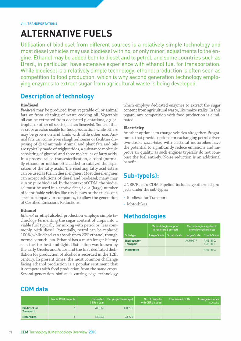
BiodieselBiodiesel may be produced from vegetable oil or animal fats or from cleaning of waste cooking oil. Vegetable oil can be extracted from dedicated plantations, e.g. ja-tropha, or other oil seeds (such as linseeds). Some of the-se crops are also usable for food production, while others may be grown on arid lands with little other use. Ani-mal fats can come from slaughterhouses or facilities dis-posing of dead animals. Animal and plant fats and oils are typically made of triglycerides, a substance molecule consisting of glycerol and three molecules of fatty acids. In a process called transesterification, alcohol (norma-lly ethanol or methanol) is added to catalyze the sepa-ration of the fatty acids. The resulting fatty acid esters can be used as fuel in diesel engines. Most diesel engines can accept solutions of diesel and biodiesel; many may run on pure biodiesel. In the context of CDM, the biodie-sel must be used in a captive fleet, i.e. a (large) number of identifiable vehicles like city busses or the trucks of a specific company or companies, to allow the generation of Certified Emissions Reductions.
EthanolEthanol or ethyl alcohol production employs simple te-chnology fermenting the sugar content of crops into a viable fuel typically for mixing with petrol or, less com-monly, with diesel. Potentially, petrol can be replaced 100%, while diesel can absorb up to 20% ethanol, though normally much less. Ethanol has a much longer history as a fuel for heat and light. Distillation was known by the early Greeks and Arabs and the first dedicated disti-llation for production of alcohol is recorded in the 12th century. In present times, the most common challenge facing ethanol production is a popular sentiment that it competes with food production from the same crops. Second generation biofuel is cutting edge technology
which employs dedicated enzymes to extract the sugar content from agricultural waste, like maize stalks. In this regard, any competition with food production is elimi-nated.
ElectricityAnother option is to change vehicles altogether. Progra-mmes that provide options for exchanging petrol driven two-stroke motorbikes with electrical motorbikes have the potential to significantly reduce emissions and im-prove air quality, as such engines typically do not com-bust the fuel entirely. Noise reduction is an additional benefit.
Sub-type(s):UNEP/Risoe’s CDM Pipeline includes geothermal pro-jects under the sub-types:
• Biodiesel for Transport • Motorbikes
MethodologiesMethodologies applied in registered projects
Methodologies applied in unregistered projects
Sub-type Large-Scale Small-Scale Large-Scale Small-Scale
BiodieselforTransport
ACM0017 AMS-III.C.AMS-III.T.
Motorbikes AMS-III.C.
ALTERNATIVEFUELSUtilisation of biodiesel from different sources is a relatively simple technology and most diesel vehicles may use biodiesel with no, or only minor, adjustments to the en-gine. Ethanol may be added both to diesel and to petrol, and some countries such as Brazil, in particular, have extensive experience with ethanol fuel for transportation. While biodiesel is a relatively simple technology, ethanol production is often seen as competition to food production, which is why second generation technology emplo-ying enzymes to extract sugar from agricultural waste is being developed.
CDMdataNo. of CDM projects Estimated
CERs / yearPer project (average) No. of projects
with CERs issuedTotal issued CERs Average issuance
success
BiodieselforTransport
6 783,853 130,231 - - -
Motorbikes 4 130,863 33,275 - - -
Descriptionoftechnology
VIII. TRANSPORTATIONS
CDM Technology & Methodology Overview 201072


This publication has been produced with the assistance of the European Union
UNEP Risø Centre(URC)National Laboratory Technical University of Denmark – DTUBldg. 110, P.O. Box 49DK-4000 Roskilde, DenmarkFax +45 4677 5199www.uneprisoe.dk
Related Documents