USDOE TOP-OF-RAIL LUBRICANT PROJECT Final Report to U.S. Department of Energy Office of Transportation Technology Office of Heavy Vehicles Technologies Argonne National Laboratory Mohumad F. Alzoubi, George R. Fenske, Robert A. Erck Energy Technology Division / Tribology Section Amrit S. Boparai Chemical Technology Division / Analytical Chemistry Laboratory Argonne National Laboratory Feb. 2000

Welcome message from author
This document is posted to help you gain knowledge. Please leave a comment to let me know what you think about it! Share it to your friends and learn new things together.
Transcript
USDOE TOP-OF-RAIL LUBRICANT PROJECT
Final Report
to
U.S. Department of EnergyOffice of Transportation Technology
Office of Heavy Vehicles Technologies
Argonne National Laboratory
Mohumad F. Alzoubi, George R. Fenske, Robert A. ErckEnergy Technology Division / Tribology Section
Amrit S. BoparaiChemical Technology Division / Analytical Chemistry Laboratory
Argonne National LaboratoryFeb. 2000
DisclaimerThis report was prepared as an account of work sponsored by an agency of theUnited States Government. Neither the United States Government nor anyagency thereof, nor The University of Chicago, nor any of their employeesor officers, makes any warranty, express or implied, or assumes any legal liabilityor responsibility for the accuracy, completeness, or usefulness of any information,apparatus, product, or process disclosed, or represents that its use would notinfringe privately owned rights. Reference herein to any specific commercialproduct, process, or service by trade name, trademark, manufacturer, orotherwise does not necessarily constitute or imply its endorsement,recommendation, or favoring by the United States Government or any agencythereof. The views and opinions of document authors expressed herein do notnecessarily state or reflect those of the United States Government or any agencythereof, Argonne National Laboratory, or The University of Chicago.
iii
CONTENTS
1 EXECUTIVE SUMMARY .................................................................................................. 1
2 INTRODUCTION............................................................................................................... 3
2.1 Introduction................................................................................................................. 32.2 Literature Review......................................................................................................... 32.3 Objectives of Research................................................................................................ 62.4 Research Approach ..................................................................................................... 6
3 LA 4000 WHEEL AND RAIL SIMULATOR TESTING FACILITY.................................. 7
3.1 Introduction................................................................................................................. 73.2 The Testing Facility....................................................................................................... 73.3 System Modification by Argonne.................................................................................. 93.4 LA4000 Testing Procedure .......................................................................................... 113.5 Field Parameter Simulation........................................................................................... 12
4 EXPERIMENTAL RESULTS AND DISSCUSSION.......................................................... 13
4.1 Introduction................................................................................................................. 134.2 Friction/Time Results.................................................................................................... 13
4.2.1 Effect of Angle of attack................................................................................... 134.2.2 Effect of Arm Load.......................................................................................... 134.2.3 Effect of Lubricant Volume Quantity................................................................. 14
4.3 By-Product Results ...................................................................................................... 154.3.1 Volatile Samples .............................................................................................. 154.3.2 Semivolatile Samples........................................................................................ 19
5 CONCLUSIONS AND RECOMMENDATIONS.............................................................. 28
6 REFERENCES .................................................................................................................... 29
iv
TABLES
1 Relative composition of analytes in collected gas .................................................................... 22
2 Target Compound List (TCL)................................................................................................ 23
3 Composition of TOR Lubricant 483-98-6004 before use....................................................... 24
4 Composition of TOR Lubricant 483-98-6004 after use.......................................................... 24
5 Target Compound List (TCL)................................................................................................ 24
FIGURES
1 Installation layout of Sentraen 2000TM ................................................................................... 5
2 Functional block diagram of Sentraen 2000TM ....................................................................... 5
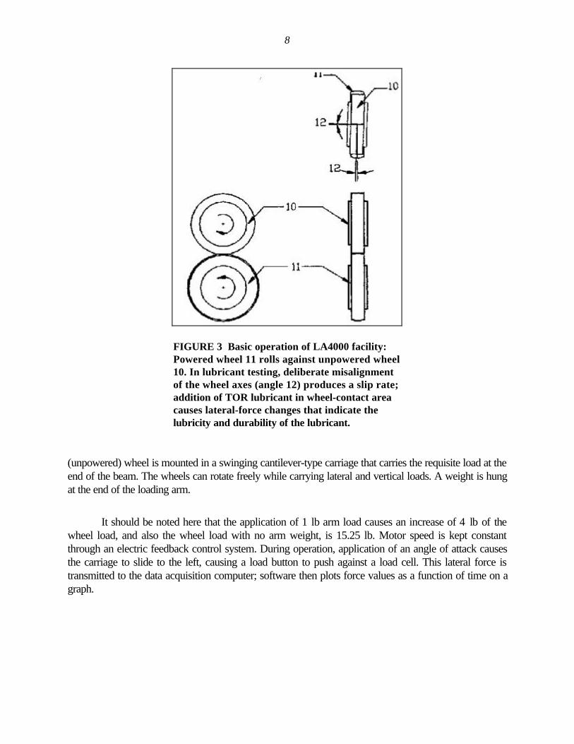
3 Basic operation of LA4000 facility: Powered wheel 11 rolls againstunpowered wheel 10. In lubricant testing, deliberate misalignment ofthe wheel axes (angle 12) produces a slip rate; addition of TOR lubricantin wheel-contact area causes lateral-force changes that indicate thelubricity and durability of the lubricant. ................................................................................... 8
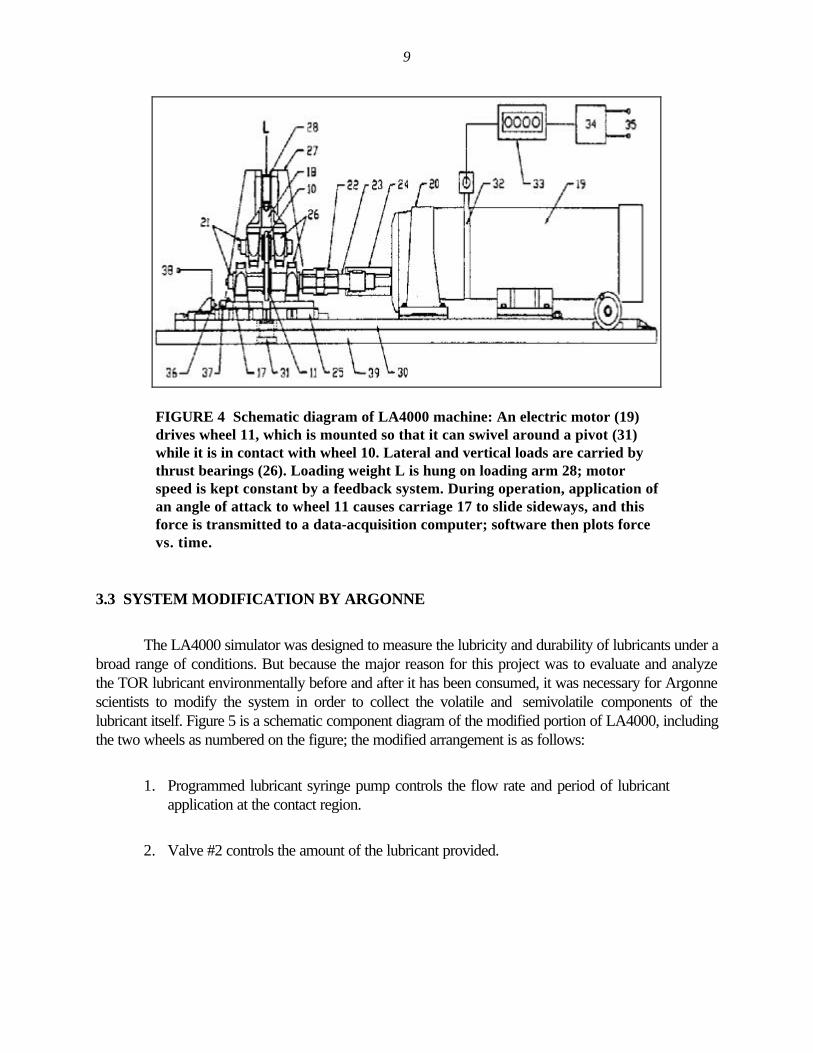
4 Schematic diagram of LA4000 machine: An electric motor (19) drives wheel 11,which is mounted so that it can swivel around a pivot (31) while it is in contactwith wheel 10. Lateral and vertical loads are carried by thrust bearings (26).Loading weight L is hung on loading arm 28; motor speed is kept constant by afeedback system. During operation, application of an angle of attack to wheel 11causes carriage 17 to slide sideways, and this force is transmitted to adata-acquisition computer; software then plots force vs. time.................................................. 9
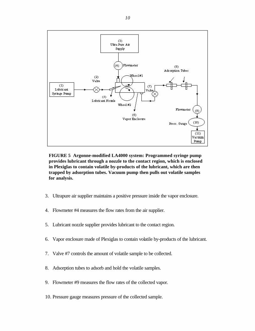
5 Argonne-modified LA4000 system: Programmed syringe pump provideslubricant through a nozzle to the contact region, which is enclosed inPlexiglas to contain volatile by-products of the lubricant, which are thentrapped by adsorption tubes. Vacuum pump then pulls out volatile samplesfor analysis............................................................................................................................ 10
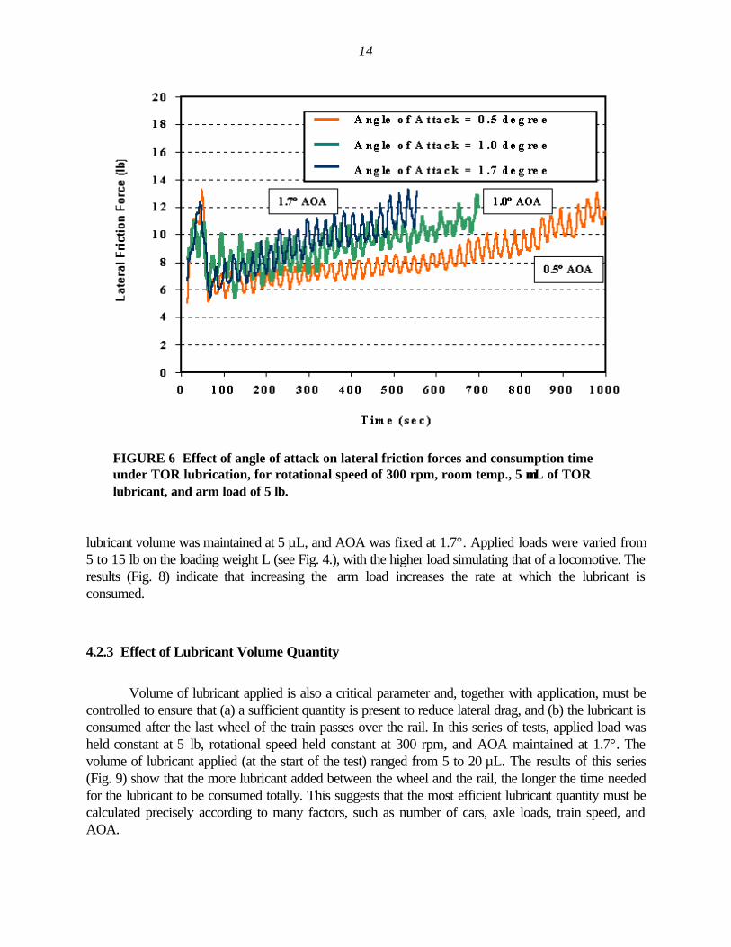
6 Effect of angle of attack on lateral friction forces and consumption time underTOR lubrication, for rotational speed of 300 rpm, room temp., 5 µL of TORlubricant, and arm load of 5 lb. .............................................................................................. 14
v
FIGURES (CONT.)
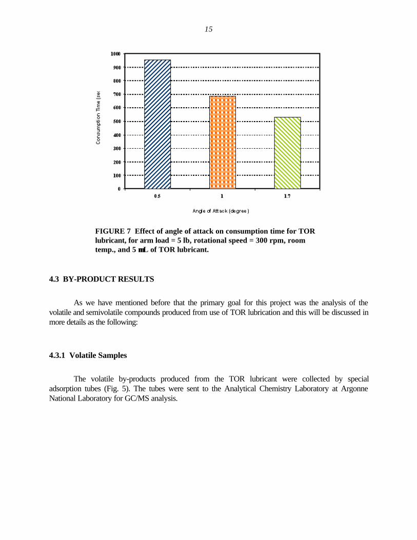
7 Effect of angle of attack on consumption time for TOR lubricant, for armload = 5 lb, rotational speed = 300 rpm, room temp., and 5 µL of TOR lubricant................... 15
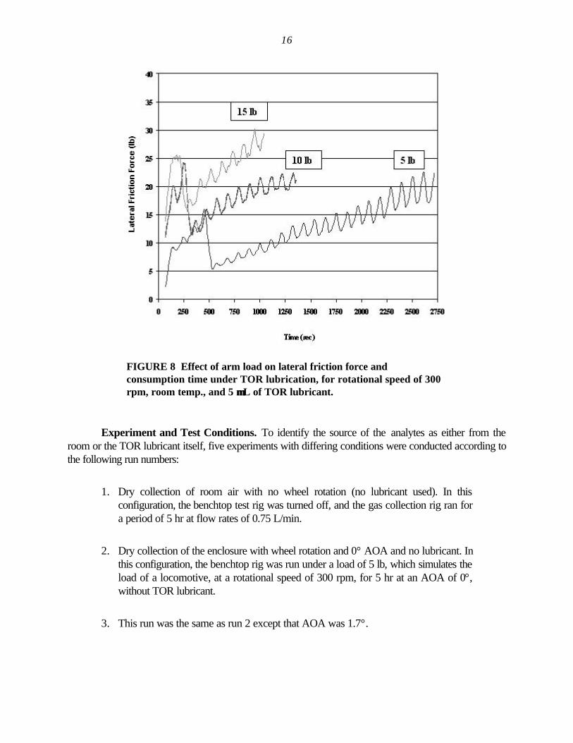
8 Effect of arm load on lateral friction force and consumption time under TORlubrication, for rotational speed of 300 rpm, room temp., and 5 µL of TOR lubricant.............. 16
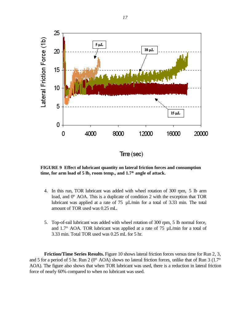
9 Effect of lubricant quantity on lateral friction forces and consumption time,for arm load of 5 lb, room temp., and 1.7° angle of attack...................................................... 17
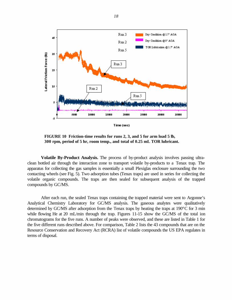
10 Friction-time results for runs 2, 3, and 5 for arm load 5 lb, 300 rpm, period of5 hr, room temp., and total of 0.25 mL TOR lubricant............................................................ 18
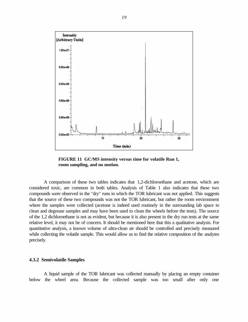
11 GC/MS intensity versus time for volatile Run 1, room sampling, and no motion. ...................... 19
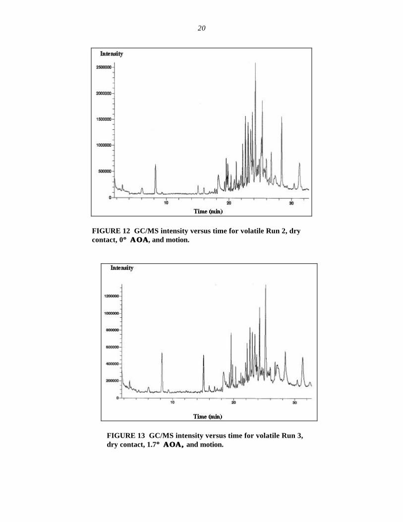
12 GC/MS intensity versus time for volatile Run 2, dry contact, 0° ΑΟΑ, and motion.................. 20
13 GC/MS intensity versus time for volatile Run 3, dry contact, 1.7° ΑΟΑ, and motion............... 20
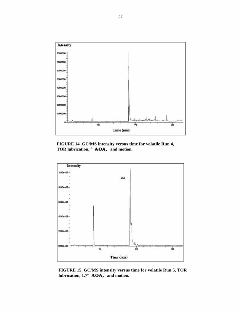
14 GC/MS intensity versus time for volatile Run 4, TOR lubrication, ° ΑΟΑ, and motion............................................................................................................................ 21
15 GC/MS intensity versus time for volatile Run 5, TOR lubrication, 1.7° ΑΟΑ, and motion............................................................................................................................ 21
16 GC/MS intensity versus time for semivolatile or TOR lubricant before use............................... 26
17 GC/MS intensity versus time for semivolatile or TOR lubricant after use.................................. 26
18 Mass spectrum of 1,2 propanediol from sample standard from thecomputerized library spectra.................................................................................................. 27
1
U.S. DEPARTMENT OF ENERGY TOP-OF-RAILLUBRICANT PROJECT
by
M.F. Alzoubi, G.R. Fenske, R.A. Erck, andA.S. Boparai
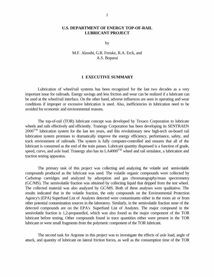
1 EXECUTIVE SUMMARY
Lubrication of wheel/rail systems has been recognized for the last two decades as a veryimportant issue for railroads. Energy savings and less friction and wear can be realized if a lubricant canbe used at the wheel/rail interface. On the other hand, adverse influences are seen in operating and wearconditions if improper or excessive lubrication is used. Also, inefficiencies in lubrication need to beavoided for economic and environmental reasons.
The top-of-rail (TOR) lubricant concept was developed by Texaco Corporation to lubricatewheels and rails effectively and efficiently. Tranergy Corporation has been developing its SENTRAEN2000TM lubrication system for the last ten years, and this revolutionary new high-tech on-board raillubrication system promises to dramatically improve the energy efficiency, performance, safety, andtrack environment of railroads. The system is fully computer-controlled and ensures that all of thelubricant is consumed as the end of the train passes. Lubricant quantity dispensed is a function of grade,speed, curve, and axle load. Tranergy also has its LA4000TM wheel and rail simulator, a lubrication andtraction testing apparatus.
The primary task of this project was collecting and analyzing the volatile and semivolatilecompounds produced as the lubricant was used. The volatile organic compounds were collected byCarbotrap cartridges and analyzed by adsorption and gas chromatography/mass spectrometry(GC/MS). The semivolatile fraction was obtained by collecting liquid that dripped from the test wheel.The collected material was also analyzed by GC/MS. Both of these analyses were qualitative. Theresults indicated that in the volatile fraction, the only compounds on the Environmental ProtectionAgency's (EPA) Superfund List of Analytes detected were contaminants either in the room air or fromother potential contamination sources in the laboratory. Similarly, in the semivolatile fraction none of thedetected compounds are on the EPA's Superfund List of Analytes. The major compound in thesemivolatile fraction is 1,2-propanediol, which was also found as the major component of the TORlubricant before testing. Other compounds found in trace quantities either were present in the TORlubricant or were small fragments from the polymeric component of the TOR lubricant.
The second task for Argonne in this project was to investigate the effects of axle load, angle ofattack, and quantity of lubricant on lateral friction forces, as well as the consumption time of the TOR
2
lubricant. The second task was to collect and qualitatively identify any volatile and semivolatilecompounds produced upon use of the TOR lubricant.
Effects of angle of attack, axle load, and quantity of the TOR lubricant 483-98-6004 on lateralfriction forces and consumption time have been investigated by the Tribology Section at ArgonneNational Laboratory. The results show that increases in angle of attack increase the friction forces andreduce consumption time for the lubricant. Also, increases in axle load increase the rate at which thelubricant is consumed. Finally, the more TOR lubricant that is added to the wheel/rail interface, thelonger the time needed for the lubricant to be consumed totally. This suggests that lubricant quantitymust be calculated precisely according to various conditions such as speed, axle load, angle of attack,and number of cars in the train.
3
2 INTRODUCTION
2.1 INTRODUCTION
The friction and wear of railroad-car wheels caused by rolling resistance has been the subject ofmany technical studies in the US, as has been the larger area of track/train dynamics. Excessive frictionbetween car wheels and rail increases locomotive fuel consumption, reduces train speed, and causesdamage, such as track degradation, wheel and rail wear, and hunting (hunting is caused by disturbingcar, track, and traction forces; although the wheels continue at the same rotational velocity, they are ondifferent radii because of coning). Thus, wheels slip on the rail and the axle adjusts to the larger radius;this effect is thereby transferred to the opposite rail and the hunting action continues, causing excessivewear on the rail [1]). The concept of rail lubrication has been developed over the years for severalreasons:
1. Wear and friction at the wheel/rail interface is an important technological nuisance,costing U.S. railroads more than $2 billion annually.
2. Maintenance and replacement of the rail is the biggest single dollar cost.
3. Current lubricants such as flange lubricants and application methods provide only asuperficial solution to the problem, the root cause of which is excessive lateral forcein the contact zone.
In 1995, railroads were estimated to carry more than 40% of the total freight, more than anytransportation mode in the nation. The experience of the railroad industry and railroad equipmentmanufacturers indicates that about $250 million could be saved annually from an effective program toreduce flange/rail friction by lubrication or other means [2]. Estimates indicate that about 1/3 of thesavings would come from increased fuel efficiency, 1/3 from less rail wear, and 1/3 from less wheelwear. Savings could vary considerably from place to place, depending on factors such as grades,curves, maximum speeds, and types of trains. Research with full-scale trains has shown that effectivespray lubrication of the rail can result in fuel savings of up to 25% on highly curved track and about 5%on relatively straight track. For these reasons, many railroad companies and researchers are nowdedicating intensive efforts to improve rail lubricants and the mechanisms of wheel/rail lubricatingtechnology, and to develop application equipment as well.
2.2 LITERATURE REVIEW
Significant research has been conducted on the contact mechanisms between the wheel and therail under dry and contaminated environments. Some of that research was theoretical, such as that byJohnson [3] and Kalker [4], both of whom examined the microstructure of the contact mechanism.
4
Others, such as Love [5], established the Hertzian solution of elastic contacts, which can be used topredict contact shape, size, and pressure; Ohyama [6] examined the effect of lubrication on adhesionand slip.
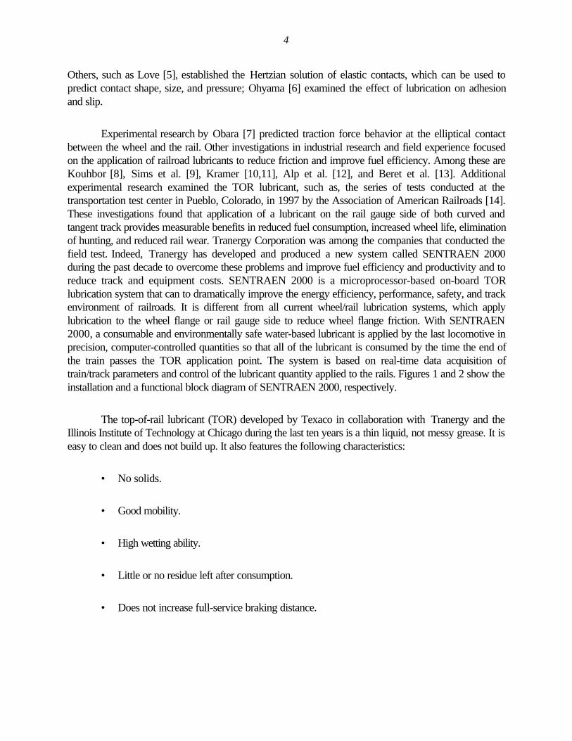
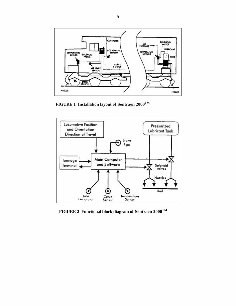
Experimental research by Obara [7] predicted traction force behavior at the elliptical contactbetween the wheel and the rail. Other investigations in industrial research and field experience focusedon the application of railroad lubricants to reduce friction and improve fuel efficiency. Among these areKouhbor [8], Sims et al. [9], Kramer [10,11], Alp et al. [12], and Beret et al. [13]. Additionalexperimental research examined the TOR lubricant, such as, the series of tests conducted at thetransportation test center in Pueblo, Colorado, in 1997 by the Association of American Railroads [14].These investigations found that application of a lubricant on the rail gauge side of both curved andtangent track provides measurable benefits in reduced fuel consumption, increased wheel life, eliminationof hunting, and reduced rail wear. Tranergy Corporation was among the companies that conducted thefield test. Indeed, Tranergy has developed and produced a new system called SENTRAEN 2000during the past decade to overcome these problems and improve fuel efficiency and productivity and toreduce track and equipment costs. SENTRAEN 2000 is a microprocessor-based on-board TORlubrication system that can to dramatically improve the energy efficiency, performance, safety, and trackenvironment of railroads. It is different from all current wheel/rail lubrication systems, which applylubrication to the wheel flange or rail gauge side to reduce wheel flange friction. With SENTRAEN2000, a consumable and environmentally safe water-based lubricant is applied by the last locomotive inprecision, computer-controlled quantities so that all of the lubricant is consumed by the time the end ofthe train passes the TOR application point. The system is based on real-time data acquisition oftrain/track parameters and control of the lubricant quantity applied to the rails. Figures 1 and 2 show theinstallation and a functional block diagram of SENTRAEN 2000, respectively.
The top-of-rail lubricant (TOR) developed by Texaco in collaboration with Tranergy and theIllinois Institute of Technology at Chicago during the last ten years is a thin liquid, not messy grease. It iseasy to clean and does not build up. It also features the following characteristics:
• No solids.
• Good mobility.
• High wetting ability.
• Little or no residue left after consumption.
• Does not increase full-service braking distance.
5
FIGURE 1 Installation layout of Sentraen 2000TM
FIGURE 2 Functional block diagram of Sentraen 2000TM
6
• Can be consumed by passage of 10 to 10,000 wheels, depending on quantityapplied and track condition.
To date, however, an independent study of the performance and biodegradability of the TORlubricant has not been conducted. This motivated the U.S. Department of Energy to sponsor such aproject at Argonne National Laboratory to complete and evaluate this lubricant.
2.3 OBJECTIVES OF RESEARCH
The objectives of the research conducted at Argonne are centered on:
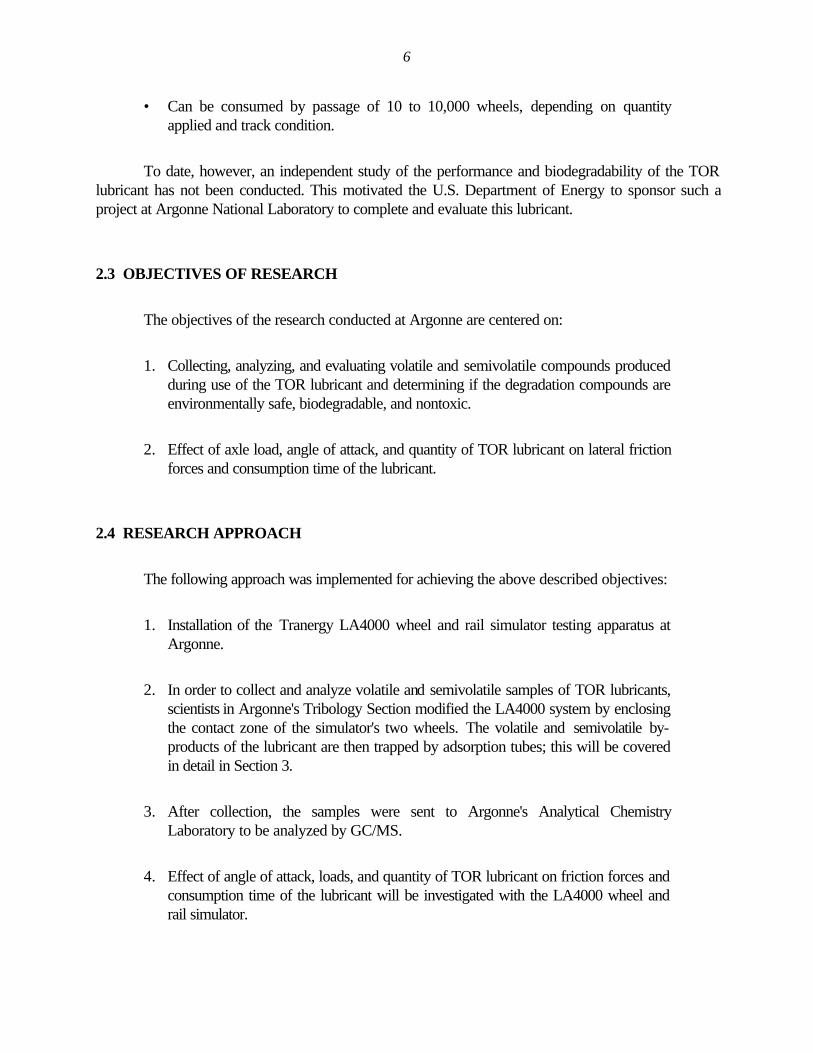
1. Collecting, analyzing, and evaluating volatile and semivolatile compounds producedduring use of the TOR lubricant and determining if the degradation compounds areenvironmentally safe, biodegradable, and nontoxic.
2. Effect of axle load, angle of attack, and quantity of TOR lubricant on lateral frictionforces and consumption time of the lubricant.
2.4 RESEARCH APPROACH
The following approach was implemented for achieving the above described objectives:
1. Installation of the Tranergy LA4000 wheel and rail simulator testing apparatus atArgonne.
2. In order to collect and analyze volatile and semivolatile samples of TOR lubricants,scientists in Argonne's Tribology Section modified the LA4000 system by enclosingthe contact zone of the simulator's two wheels. The volatile and semivolatile by-products of the lubricant are then trapped by adsorption tubes; this will be coveredin detail in Section 3.
3. After collection, the samples were sent to Argonne's Analytical ChemistryLaboratory to be analyzed by GC/MS.
4. Effect of angle of attack, loads, and quantity of TOR lubricant on friction forces andconsumption time of the lubricant will be investigated with the LA4000 wheel andrail simulator.
7
3 LA 4000 WHEEL AND RAIL SIMULATOR TESTING FACILITY
3.1 INTRODUCTION
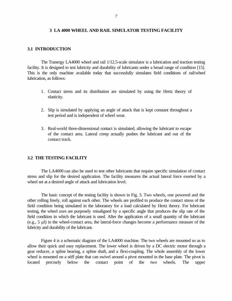
The Tranergy LA4000 wheel and rail 1/12.5-scale simulator is a lubrication and traction testingfacility. It is designed to test lubricity and durability of lubricants under a broad range of condition [15].This is the only machine available today that successfully simulates field conditions of rail/wheellubrication, as follows:
1. Contact stress and its distribution are simulated by using the Hertz theory ofelasticity.
2. Slip is simulated by applying an angle of attack that is kept constant throughout atest period and is independent of wheel wear.
3. Real-world three-dimensional contact is simulated, allowing the lubricant to escapeof the contact area. Lateral creep actually pushes the lubricant and out of thecontact track.
3.2 THE TESTING FACILITY
The LA4000 can also be used to test other lubricants that require specific simulation of contactstress and slip for the desired application. The facility measures the actual lateral force exerted by awheel set at a desired angle of attack and lubrication level.
The basic concept of the testing facility is shown in Fig. 3. Two wheels, one powered and theother rolling freely, roll against each other. The wheels are profiled to produce the contact stress of thefield condition being simulated in the laboratory for a load calculated by Hertz theory. For lubricanttesting, the wheel axes are purposely misaligned by a specific angle that produces the slip rate of thefield condition in which the lubricant is used. After the application of a small quantity of the lubricant(e.g., 5 µl) in the wheel-contact area, the lateral-force changes become a performance measure of thelubricity and durability of the lubricant.
Figure 4 is a schematic diagram of the LA4000 machine. The two wheels are mounted so as toallow their quick and easy replacement. The lower wheel is driven by a DC electric motor through agear reducer, a spline bearing, a spline shaft, and a flexi-coupling. The whole assembly of the lowerwheel is mounted on a stiff plate that can swivel around a pivot mounted in the base plate. The pivot islocated precisely below the contact point of the two wheels. The upper
8
FIGURE 3 Basic operation of LA4000 facility:Powered wheel 11 rolls against unpowered wheel10. In lubricant testing, deliberate misalignmentof the wheel axes (angle 12) produces a slip rate;addition of TOR lubricant in wheel-contact areacauses lateral-force changes that indicate thelubricity and durability of the lubricant.
(unpowered) wheel is mounted in a swinging cantilever-type carriage that carries the requisite load at theend of the beam. The wheels can rotate freely while carrying lateral and vertical loads. A weight is hungat the end of the loading arm.
It should be noted here that the application of 1 lb arm load causes an increase of 4 lb of thewheel load, and also the wheel load with no arm weight, is 15.25 lb. Motor speed is kept constantthrough an electric feedback control system. During operation, application of an angle of attack causesthe carriage to slide to the left, causing a load button to push against a load cell. This lateral force istransmitted to the data acquisition computer; software then plots force values as a function of time on agraph.
9
FIGURE 4 Schematic diagram of LA4000 machine: An electric motor (19)drives wheel 11, which is mounted so that it can swivel around a pivot (31)while it is in contact with wheel 10. Lateral and vertical loads are carried bythrust bearings (26). Loading weight L is hung on loading arm 28; motorspeed is kept constant by a feedback system. During operation, application ofan angle of attack to wheel 11 causes carriage 17 to slide sideways, and thisforce is transmitted to a data-acquisition computer; software then plots forcevs. time.
3.3 SYSTEM MODIFICATION BY ARGONNE
The LA4000 simulator was designed to measure the lubricity and durability of lubricants under abroad range of conditions. But because the major reason for this project was to evaluate and analyzethe TOR lubricant environmentally before and after it has been consumed, it was necessary for Argonnescientists to modify the system in order to collect the volatile and semivolatile components of thelubricant itself. Figure 5 is a schematic component diagram of the modified portion of LA4000, includingthe two wheels as numbered on the figure; the modified arrangement is as follows:
1. Programmed lubricant syringe pump controls the flow rate and period of lubricantapplication at the contact region.
2. Valve #2 controls the amount of the lubricant provided.
10
FIGURE 5 Argonne-modified LA4000 system: Programmed syringe pumpprovides lubricant through a nozzle to the contact region, which is enclosedin Plexiglas to contain volatile by-products of the lubricant, which are thentrapped by adsorption tubes. Vacuum pump then pulls out volatile samplesfor analysis.
3. Ultrapure air supplier maintains a positive pressure inside the vapor enclosure.
4. Flowmeter #4 measures the flow rates from the air supplier.
5. Lubricant nozzle supplier provides lubricant to the contact region.
6. Vapor enclosure made of Plexiglas to contain volatile by-products of the lubricant.
7. Valve #7 controls the amount of volatile sample to be collected.
8. Adsorption tubes to adsorb and hold the volatile samples.
9. Flowmeter #9 measures the flow rates of the collected vapor.
10. Pressure gauge measures pressure of the collected sample.
11
11. Vacuum pump is used to draw out a volatile sample.
It should be noted here that the flow rate in the flowmeter #4 should be higher than that in flowmeter #9in order to maintain positive pressure inside the vapor enclosure.
3.4 LA4000 TESTING PROCEDURE
The operating procedure under lubricated conditions is explained by the following:
• The two wheels are thoroughly cleaned with acetone and then brought together.
• Power is supplied to wheel 11 (see Fig. 4).
• The desired load is applied at the end of the load arm.
• Before applying the desired angle of attack (AOA), the AOA should be dynamicallyset to zero first by maintaining zero lateral force on the computer monitor with thehelp of the LabTech software.
• Rotational speed can be controlled directly from the motor control box, with amaximum speed of 300 rpm.
• Lubricant is applied through the lubricant nozzle supplier (Fig. 5).
• Collecting the lateral-forces data versus time can be done by Labtech software to thedesired number of cycles (or desired time).
• Collecting the volatile by-products of TOR lubricant is achieved with the adsorptiontubes, while liquid (semivolatile) samples are collected manually in a container belowthe wheel contact area.
• After collecting volatile samples, the adsorption tubes must be kept at a very lowtemperature.
For more details about the testing procedure, the reader should refer to the LA4000 operating manual[15].
12
3.5 FIELD PARAMETER SIMULATION
The LA4000TM simulates the following field conditions:
• The arm load range of 5 to 15 lb in the lab simulates loads from a fully loadedrailcar up to a locomotive. It should be noted
• The 300-rpm rotational speed in the lab simulates a speed in the field of 6 to 7 mph.
• The 1.7° angle of attack is equivalent to the maximum lateral slip in the field ofalmost 3%.
• The temperature range in the lab is from room temperature to 150°F.
• Lubricant quantity can be dispensed precisely.
13
4 EXPERIMENTAL RESULTS AND DISSCUSSION
4.1 INTRODUCTION
While the major focus of this project was on environmental effect, it was first necessary todefine the range of test parameters of the experiment. To do this, several tests were performed toevaluate the lubricant consumption time as functions of angle of attack, axle load, and lubricant volumequantity.
4.2 FRICTION/TIME RESULTS
The first test series of this research focused on investigating the effects on lateral friction forces andconsumption time of angle of attack (AOA), axle load, speed, and required lubricant quantity of TORlubricant 483-98-6004. Consumption time for the lubricant is defined as the time needed for thelubricant to be consumed totally (i.e., when the measured lateral forces equal those of the base line forthe unlubricated system).
4.2.1 Effect of Angle of attack
The AOA is a major parameters affecting friction and wear in the field, especially in dryenvironments [16]. In this test series, the load, rotational speed, and initial lubricant quantity was heldconstant and the AOA was varied to determine its impact on friction force and consumption time. Thearm load was 5 lb, which simulates the stresses from a fully loaded rail-car. Rotational speed was heldconstant at 300 rpm to simulating a train speed of 6 to 7 mph. TOR volume lubricant was 5 µL, andAOA was varied from 0.5° to 1.7°. Three sets of experiments for AOAs of 0.5°, 1.0°, and 1.7° wereperformed in order to study the effect of AOA on lateral friction force and lubricant consumption time.The results show (see Fig. 6) that increases in AOA increase friction force and reduce the lubricantconsumption time. The reason is that for higher AOA, there is more friction forces in the lateraldirection, and will increase the shearing rate of the lubricant, which causes the lubricant to be consumedfaster than when smaller angles are used. From Fig. 6, the consumption time versus AOA can becalculated and plotted in Fig. 7, which indicates that consumption time is higher at smaller AOAs than atlarger AOAs.
4.2.2 Effect of Arm Load
Another variable that affects lubricant consumption rate (and thus the rate at which it must be applied) isapplied load. In this series of tests, the rotational speed was held constant at 300 rpm;
14
FIGURE 6 Effect of angle of attack on lateral friction forces and consumption timeunder TOR lubrication, for rotational speed of 300 rpm, room temp., 5 µµL of TORlubricant, and arm load of 5 lb.
lubricant volume was maintained at 5 µL, and AOA was fixed at 1.7°. Applied loads were varied from5 to 15 lb on the loading weight L (see Fig. 4.), with the higher load simulating that of a locomotive. Theresults (Fig. 8) indicate that increasing the arm load increases the rate at which the lubricant isconsumed.
4.2.3 Effect of Lubricant Volume Quantity
Volume of lubricant applied is also a critical parameter and, together with application, must becontrolled to ensure that (a) a sufficient quantity is present to reduce lateral drag, and (b) the lubricant isconsumed after the last wheel of the train passes over the rail. In this series of tests, applied load washeld constant at 5 lb, rotational speed held constant at 300 rpm, and AOA maintained at 1.7°. Thevolume of lubricant applied (at the start of the test) ranged from 5 to 20 µL. The results of this series(Fig. 9) show that the more lubricant added between the wheel and the rail, the longer the time neededfor the lubricant to be consumed totally. This suggests that the most efficient lubricant quantity must becalculated precisely according to many factors, such as number of cars, axle loads, train speed, andAOA.
15
FIGURE 7 Effect of angle of attack on consumption time for TORlubricant, for arm load = 5 lb, rotational speed = 300 rpm, roomtemp., and 5 µµL of TOR lubricant.
4.3 BY-PRODUCT RESULTS
As we have mentioned before that the primary goal for this project was the analysis of thevolatile and semivolatile compounds produced from use of TOR lubrication and this will be discussed inmore details as the following:
4.3.1 Volatile Samples
The volatile by-products produced from the TOR lubricant were collected by specialadsorption tubes (Fig. 5). The tubes were sent to the Analytical Chemistry Laboratory at ArgonneNational Laboratory for GC/MS analysis.
16
FIGURE 8 Effect of arm load on lateral friction force andconsumption time under TOR lubrication, for rotational speed of 300rpm, room temp., and 5 µµL of TOR lubricant.
Experiment and Test Conditions. To identify the source of the analytes as either from theroom or the TOR lubricant itself, five experiments with differing conditions were conducted according tothe following run numbers:
1. Dry collection of room air with no wheel rotation (no lubricant used). In thisconfiguration, the benchtop test rig was turned off, and the gas collection rig ran fora period of 5 hr at flow rates of 0.75 L/min.
2. Dry collection of the enclosure with wheel rotation and 0° AOA and no lubricant. Inthis configuration, the benchtop rig was run under a load of 5 lb, which simulates theload of a locomotive, at a rotational speed of 300 rpm, for 5 hr at an AOA of 0°,without TOR lubricant.
3. This run was the same as run 2 except that AOA was 1.7°.
17
FIGURE 9 Effect of lubricant quantity on lateral friction forces and consumptiontime, for arm load of 5 lb, room temp., and 1.7°° angle of attack.
4. In this run, TOR lubricant was added with wheel rotation of 300 rpm, 5 lb armload, and 0° AOA. This is a duplicate of condition 2 with the exception that TORlubricant was applied at a rate of 75 µL/min for a total of 3.33 min. The totalamount of TOR used was 0.25 mL.
5. Top-of-rail lubricant was added with wheel rotation of 300 rpm, 5 lb normal force,and 1.7° AOA. TOR lubricant was applied at a rate of 75 µL/min for a total of3.33 min. Total TOR used was 0.25 mL for 5 hr.
Friction/Time Series Results. Figure 10 shows lateral friction forces versus time for Run 2, 3,and 5 for a period of 5 hr. Run 2 (0° AOA) shows no lateral friction forces, unlike that of Run 3 (1.7°AOA). The figure also shows that when TOR lubricant was used, there is a reduction in lateral frictionforce of nearly 60% compared to when no lubricant was used.
18
FIGURE 10 Friction-time results for runs 2, 3, and 5 for arm load 5 lb,300 rpm, period of 5 hr, room temp., and total of 0.25 mL TOR lubricant.
Volatile By-Product Analysis. The process of by-product analysis involves passing ultra-clean bottled air through the interaction zone to transport volatile by-products to a Tenax trap. Theapparatus for collecting the gas samples is essentially a small Plexiglas enclosure surrounding the twocontacting wheels (see Fig. 5). Two adsorption tubes (Tenax traps) are used in series for collecting thevolatile organic compounds. The traps are then sealed for subsequent analysis of the trappedcompounds by GC/MS.
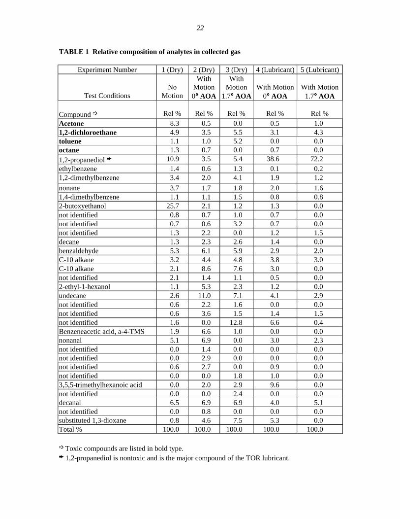
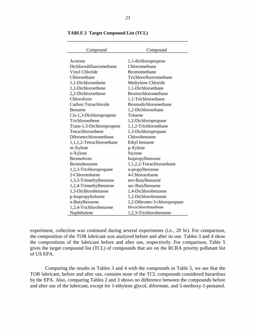
After each run, the sealed Tenax traps containing the trapped material were sent to Argonne’sAnalytical Chemistry Laboratory for GC/MS analysis. The gaseous analytes were qualitativelydetermined by GC/MS after adsorption from the Tenax traps by heating the traps at 190°C for 3 minwhile flowing He at 20 mL/min through the trap. Figures 11-15 show the GC/MS of the total ionchromatograms for the five runs. A number of peaks were observed, and these are listed in Table 1 forthe five different runs described above. For comparison, Table 2 lists the 43 compounds that are on theResource Conservation and Recovery Act (RCRA) list of volatile compounds the US EPA regulates interms of disposal.
19
FIGURE 11 GC/MS intensity versus time for volatile Run 1,room sampling, and no motion.
A comparison of these two tables indicates that 1,2-dichloroethane and acetone, which areconsidered toxic, are common in both tables. Analysis of Table 1 also indicates that these twocompounds were observed in the "dry" runs in which the TOR lubricant was not applied. This suggeststhat the source of these two compounds was not the TOR lubricant, but rather the room environmentwhere the samples were collected (acetone is indeed used routinely in the surrounding lab space toclean and degrease samples and may have been used to clean the wheels before the tests). The sourceof the 1,2 dichloroethane is not as evident, but because it is also present in the dry run tests at the samerelative level, it may not be of concern. It should be mentioned here that this a qualitative analysis. Forquantitative analysis, a known volume of ultra-clean air should be controlled and precisely measuredwhile collecting the volatile sample. This would allow us to find the relative composition of the analytesprecisely.
4.3.2 Semivolatile Samples
A liquid sample of the TOR lubricant was collected manually by placing an empty containerbelow the wheel area. Because the collected sample was too small after only one
20
FIGURE 12 GC/MS intensity versus time for volatile Run 2, drycontact, 0°° ΑΟΑ ΑΟΑ, and motion.
FIGURE 13 GC/MS intensity versus time for volatile Run 3,dry contact, 1.7°° ΑΟΑ, ΑΟΑ, and motion.
21
FIGURE 14 GC/MS intensity versus time for volatile Run 4,TOR lubrication, °° ΑΟΑ, ΑΟΑ, and motion.
FIGURE 15 GC/MS intensity versus time for volatile Run 5, TORlubrication, 1.7°° ΑΟΑ, ΑΟΑ, and motion.
Time (min)
22
TABLE 1 Relative composition of analytes in collected gas
Experiment Number 1 (Dry) 2 (Dry) 3 (Dry) 4 (Lubricant) 5 (Lubricant)
Test ConditionsNo
Motion
WithMotion0°°°° AOA
WithMotion
1.7°°°° AOAWith Motion
0°°°° AOAWith Motion
1.7°°°° AOA
Compound ➩ Rel % Rel % Rel % Rel % Rel %Acetone 8.3 0.5 0.0 0.5 1.01,2-dichloroethane 4.9 3.5 5.5 3.1 4.3toluene 1.1 1.0 5.2 0.0 0.0octane 1.3 0.7 0.0 0.7 0.01,2-propanediol ➨ 10.9 3.5 5.4 38.6 72.2ethylbenzene 1.4 0.6 1.3 0.1 0.21,2-dimethylbenzene 3.4 2.0 4.1 1.9 1.2nonane 3.7 1.7 1.8 2.0 1.61,4-dimethylbenzene 1.1 1.1 1.5 0.8 0.82-butoxyethanol 25.7 2.1 1.2 1.3 0.0not identified 0.8 0.7 1.0 0.7 0.0not identified 0.7 0.6 3.2 0.7 0.0not identified 1.3 2.2 0.0 1.2 1.5decane 1.3 2.3 2.6 1.4 0.0benzaldehyde 5.3 6.1 5.9 2.9 2.0C-10 alkane 3.2 4.4 4.8 3.8 3.0C-10 alkane 2.1 8.6 7.6 3.0 0.0not identified 2.1 1.4 1.1 0.5 0.02-ethyl-1-hexanol 1.1 5.3 2.3 1.2 0.0undecane 2.6 11.0 7.1 4.1 2.9not identified 0.6 2.2 1.6 0.0 0.0not identified 0.6 3.6 1.5 1.4 1.5not identified 1.6 0.0 12.8 6.6 0.4Benzeneacetic acid, a-4-TMS 1.9 6.6 1.0 0.0 0.0nonanal 5.1 6.9 0.0 3.0 2.3not identified 0.0 1.4 0.0 0.0 0.0not identified 0.0 2.9 0.0 0.0 0.0not identified 0.6 2.7 0.0 0.9 0.0not identified 0.0 0.0 1.8 1.0 0.03,5,5-trimethylhexanoic acid 0.0 2.0 2.9 9.6 0.0not identified 0.0 0.0 2.4 0.0 0.0decanal 6.5 6.9 6.9 4.0 5.1not identified 0.0 0.8 0.0 0.0 0.0substituted 1,3-dioxane 0.8 4.6 7.5 5.3 0.0Total % 100.0 100.0 100.0 100.0 100.0
➩ Toxic compounds are listed in bold type.➨ 1,2-propanediol is nontoxic and is the major compound of the TOR lubricant.
23
TABLE 2 Target Compound List (TCL)
Compound Compound
Acetone 1,1-dichloropropeneDichlorodifluoromethane ChloromethaneVinyl Chloride BromomethaneChloroethane Trichlorofluoromethane1,1-Dichloroethene Methylene Chloride1,2-Dichloroethene 1,1-Dichloroethane2,2-Dichloroethene BromochloromethaneChloroform 1,1-TrichloroethaneCarbon Tetrachloride BromodichloromethaneBenzene 1,2-DichloroethaneCis-1,3-Dichloropropene TolueneTrichloroethene 1,2-DichloropropaneTrans-1,3-Dichloropropene 1,1,2-TrichloroethaneTetrachloroethene 1,3-DichloropropaneDibromochloromethane Chlorobenzene1,1,1,2-Tetrachloroethane Ethyl benzenem-Xylene p-Xyleneo-Xylene StyreneBromoform IsopropylbenzeneBromobenzene 1,1,2,2-Tetrachloroethane1,2,3-Trichloropropane n-propylbenzene2-Chlorotoluene 4-Chlorotoluene1,3,5-Trimethylbenzene tert-Butylbenzene1,2,4-Trimethylbenzene sec-Butylbenzene1,3-Dichlorobenzene 1,4-Dichlorobenzenep-Isopropyltoluene 1,2-Dichlorobenzenen-Butylbenzene 1,2-Dibromo-3-chloropropane1,2,4-Trichlorobenzene HexachlorobutadieneNaphthalene 1,2,3-Trichlorobenzene
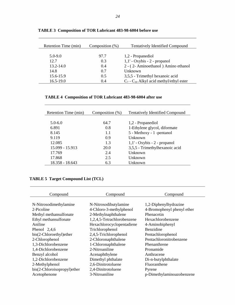
experiment, collection was continued during several experiments (i.e., 20 hr). For comparison,the composition of the TOR lubricant was analyzed before and after its use. Tables 3 and 4 showthe compositions of the lubricant before and after use, respectively. For comparison, Table 5gives the target compound list (TCL) of compounds that are on the RCRA priority pollutant listof US EPA.
Comparing the results in Tables 3 and 4 with the compounds in Table 5, we see that theTOR lubricant, before and after use, contains none of the TCL compounds considered hazardousby the EPA. Also, comparing Tables 2 and 3 shows no difference between the compounds beforeand after use of the lubricant, except for 1-ethylene glycol, diformate, and 5-methoxy-1-pentanol.
24
TABLE 3 Composition of TOR Lubricant 483-98-6004 before use
Retention Time (min) Composition (%) Tentatively Identified Compound
5.0-9.0 97.7 1,2 - Propanediol12.7 0.3 1,1' - Oxybis - 2 - propanol13.2-14.0 0.4 2 - ( 2- Aminoethanol ) Amino ethanol14.8 0.7 Unknown15.6-15.9 0.5 3,5,5 - Trimethyl hexanoic acid16.5-19.0 0.4 C7 - C10 Alkyl acid methyl/ethyl ester
TABLE 4 Composition of TOR Lubricant 483-98-6004 after use
Retention Time (min) Composition (%) Tentatively Identified Compound
5.0-6.0 64.7 1,2 - Propanediol6.891 0.8 1-Ethylene glycol, diformate8.145 1.1 5 - Methoxy - 1 -pentanol9.119 0.9 Unknown12.085 1.3 1,1' - Oxybis - 2 - propanol15.099 - 15.913 20.0 3,5,5 - Trimethylhexanoic acid17.769 2.4 Unknown17.868 2.5 Unknown18.358 - 18.643 6.3 Unknown
TABLE 5 Target Compound List (TCL)
Compound Compound Compound
N-Nitrosodimethylamine N-Nitrosodibutylamine 1,2-Diphenylhydrazine2-Picoline 4-Chloro-3-methylphenol 4-Bromophenyl phenyl etherMethyl methansulfonate 2-Methylnaphthalene PhenacetinEthyl methansulfonate 1,2,4,5-Tetrachlorobenzene HexachlorobenzeneAniline Hexachlorocyclopentadiene 4-AminobiphenylPhenol 2,4,6 Trichlorophenol Benzidinebis(2-Chloroethyl)ether 2,4,5-Trichlorophenol Pentachlorophenol2-Chlorophenol 2-Chloronaphthalene Pentachloronitrobenzene1,3-Dichlorobenzene 1-Chloronaphthalene Phenanthrene1,4-Dichlorobenzene 2-Nitroaniline PronamideBenzyl alcohol Acenaphthylene Anthracene1,2-Dichlorobenzene Dimethyl phthalate Di-n-butylphthalate2-Methylphenol 2,6-Dinitrotoluene Fluoranthenebis(2-Chloroisopropyl)ether 2,4-Dinitrotoluene PyreneAcetophenone 3-Nitroaniline p-Dimethylaminoazobenzene
25
TABLE 5 (Cont.)
Compound Compound Compound
Hexachloroethane Acenaphthene ButylbenzylphthalateN-nitroso-di-n-propylamine 2,4-Dinitrophenol Benzo (a) anthracene4-Methylphenol Dibenzofuran 3,3'-DichlorobenidineNitrobenzene Pentachlorobenzene ChryseneN-Nitrosopiperidine 4-Nitrophenol bis(2-ethylhexyl)phthalateIsophorone 2-Naphthylamine Di-n-octylphthalate2-Nitrophenol 1-Naphthylamine Benzo(b)fluoranthene2,4-Dimethyphenol 2,3,4,6-Tetrachlorophenol 7,12-Dimethylbenz(a)anthracene2,4-Dichlorophenol 4-Chlorophenol phenyl ether Benzo(a)pyreneBenzoic acid Diethylphthalate 3-Methylcholanthrene1,2,4-Trichlorobenzene 4-Nitroaniline Dibenz(a,j)acridineNaphthalene 4,6-Dinitro-2-methylphenol Ideno(1,2,3-cd)pyrene4-Chloraniline a,a-Dimethylphenethylamine Dibenzo(a,h)anthracenebis(2-Chloroethoxy)methane Fluorene Benzo(k)fluoranthene
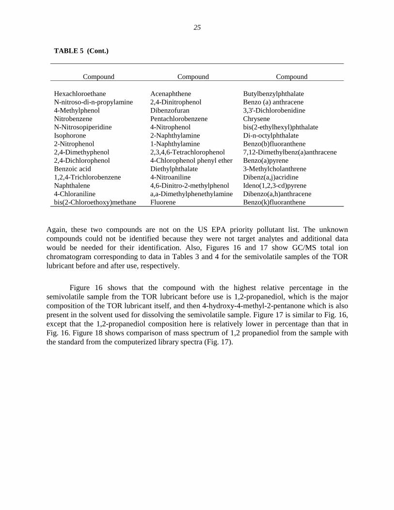
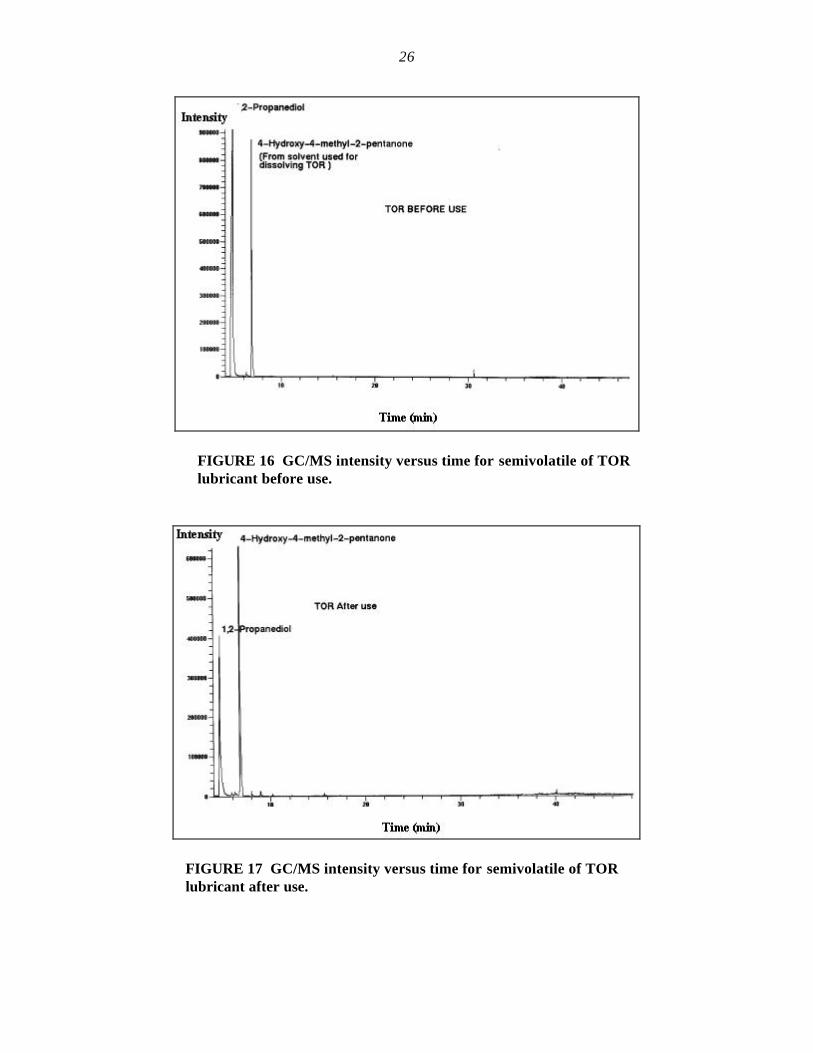
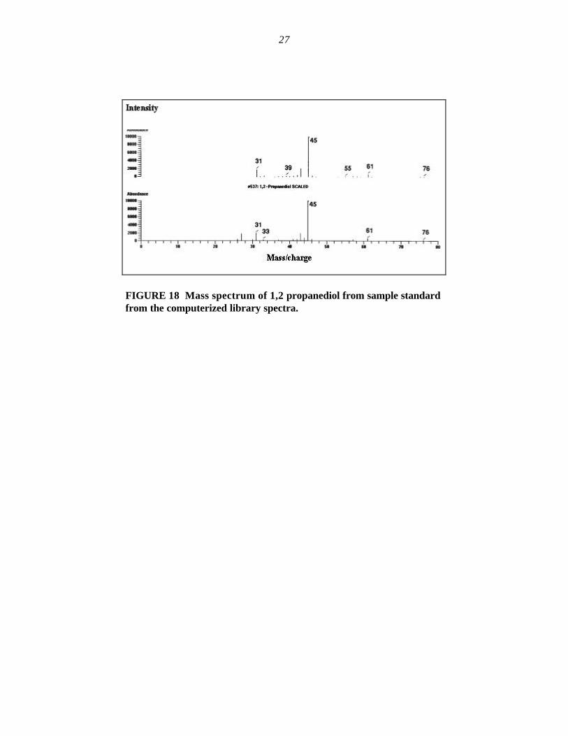
Again, these two compounds are not on the US EPA priority pollutant list. The unknowncompounds could not be identified because they were not target analytes and additional datawould be needed for their identification. Also, Figures 16 and 17 show GC/MS total ionchromatogram corresponding to data in Tables 3 and 4 for the semivolatile samples of the TORlubricant before and after use, respectively.
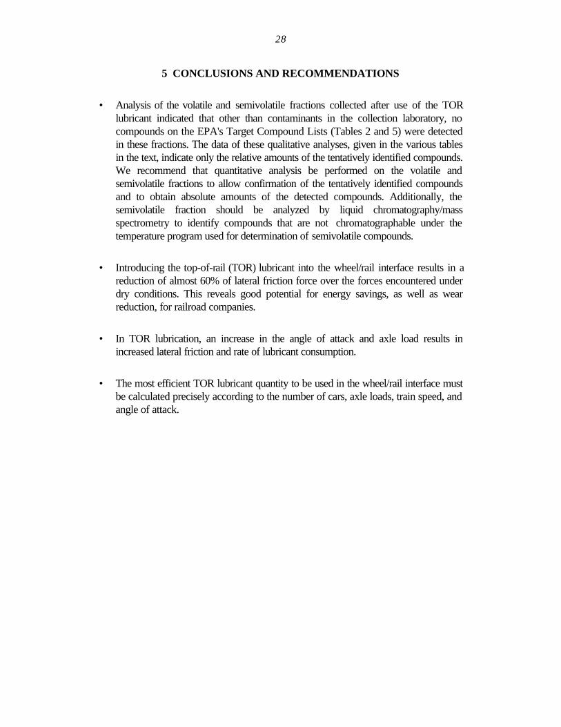
Figure 16 shows that the compound with the highest relative percentage in thesemivolatile sample from the TOR lubricant before use is 1,2-propanediol, which is the majorcomposition of the TOR lubricant itself, and then 4-hydroxy-4-methyl-2-pentanone which is alsopresent in the solvent used for dissolving the semivolatile sample. Figure 17 is similar to Fig. 16,except that the 1,2-propanediol composition here is relatively lower in percentage than that inFig. 16. Figure 18 shows comparison of mass spectrum of 1,2 propanediol from the sample withthe standard from the computerized library spectra (Fig. 17).
26
FIGURE 16 GC/MS intensity versus time for semivolatile of TORlubricant before use.
FIGURE 17 GC/MS intensity versus time for semivolatile of TORlubricant after use.
27
FIGURE 18 Mass spectrum of 1,2 propanediol from sample standardfrom the computerized library spectra.
28
5 CONCLUSIONS AND RECOMMENDATIONS
• Analysis of the volatile and semivolatile fractions collected after use of the TORlubricant indicated that other than contaminants in the collection laboratory, nocompounds on the EPA's Target Compound Lists (Tables 2 and 5) were detectedin these fractions. The data of these qualitative analyses, given in the various tablesin the text, indicate only the relative amounts of the tentatively identified compounds.We recommend that quantitative analysis be performed on the volatile andsemivolatile fractions to allow confirmation of the tentatively identified compoundsand to obtain absolute amounts of the detected compounds. Additionally, thesemivolatile fraction should be analyzed by liquid chromatography/massspectrometry to identify compounds that are not chromatographable under thetemperature program used for determination of semivolatile compounds.
• Introducing the top-of-rail (TOR) lubricant into the wheel/rail interface results in areduction of almost 60% of lateral friction force over the forces encountered underdry conditions. This reveals good potential for energy savings, as well as wearreduction, for railroad companies.
• In TOR lubrication, an increase in the angle of attack and axle load results inincreased lateral friction and rate of lubricant consumption.
• The most efficient TOR lubricant quantity to be used in the wheel/rail interface mustbe calculated precisely according to the number of cars, axle loads, train speed, andangle of attack.
29
6 REFERENCES
[1] Hay, W., MS, Mgt. E., Ph.D., Rail Road Engineering, University of Illinois at Urbana-Champaign, 2 (1982) 669.
[2] Fessler, R. R., and Fenske G. R., "Reducing Friction and Wear in Heavy Vehicles," MultiyearProgram Plan, U.S. Dept. of Energy (1999) 27.
[3] Johnson, K. L. Contact Mechanics, Cambridge University Press, Cambridge, U.K. (1985).
[4] Kalker, J. J., “On the Rolling Contact of Two Elastic Bodies in the Presence of Dry Friction,” M.S. Thesis, Delft, Netherlands (1967).
[5 Love, A. E. H. “A Treatise on the Mechanical Theory of Elasticity,” Cambridge University Press,Cambridge, U.K. (1926).
[6] Ohyama, T., “Adhesion Characteristics of Wheel/Rail System and Its Control at High Speed,”Quarterly Reports of RTRI, Vol. 33, No. 1 (1992), 19-30.
[7] Obara, T., “The Behavior of Traction Force at Elliptic Contact between Wheel and Rail,” QR ofRTRI, Vol. 36, No. 3 (1995).
[8] Kouhbor, K., "Effects of Rail/Wheel Lubrication on Reduction of Energy by Computer SimulationSIMCAR," National Conference Publication - Institute of Engineers, Australia 10th InternationalWheelset Congress (1992), 311-317.
[9] Sims, R. D., Miller, K. A., and Schepmann, G., "Rail Lubrication Measurement," ASME/IEEEJoint Railroad Conf., (1996), 23-33.
[10] Kramer, J., "Rail Lubrication: Improving Application Systems," Railway Track and Structure, Vol.92, No. 7 (1996), 19-20.
[11] Kramer, J., "Rail Lubrication: Multiple Choice," Railway Track and Structure, Vol. 91, No. 8(1995), 14-15.
[12] Alp, A., Erdemir, A., and Kumar, S. "Energy and Wear Analysis in Lubricated Sliding Contact,"Wear Proceedings of the 1994 4th Int. Conf. on Contact Mechanics of Rail-Wheel System, Vol.191, No.1-2 (1996), 261-264.
30
[13] Beret, S., and Trabert, G. R., "Railroad Wheel and Track Lubrication: Assessment ofEffectiveness," National Lubricating Grease Institute, Vol. 55, No. 2 (1191), 7-43.
[14] Kumar, S., and Dyavanapalli, V., Tranergy Corp., "Improved Methods for Increasing Wheel/RailAdhesion in the Presence of Natural Contaminants," Final Report (1997).
[15] Kumar, S., and Dyavanapalli, V., Tranergy Corp., "The LA4000 Lubrication/Adhesion TestingSystem," (Operating Manual), 2 (1998) 3.
[16] Kumar, S., and Alzoubi, M. F., Illinois Institute of Technology, Wheel/Rail Adhesion WearInvestigation Using A Quarter-Scale Laboratory Test Facility," ASME/IEEE Joint Railroad Conf.(1996) 247-254.
Related Documents