By Mostafa El-koumy

Welcome message from author
This document is posted to help you gain knowledge. Please leave a comment to let me know what you think about it! Share it to your friends and learn new things together.
Transcript

By Mostafa El-koumy
Introduction
to
USB
?
ORIGINAL MOTIVATION
merging of computing and communication.
Flexibility.
Ease of using by an end user.
High speed.
Port expansion.
USB SPEEDS
High Speed - 480 Mbits/s.
Full Speed - 12 Mbits/s.
Low Speed - 1.5 Mbits/s.
USB version 1 supports Low and Full speeds.
USB 2.0 that in our hands today supports the
three speeds.

USB BUS
USB is host controlled so only one host can per bus and does not support any form of multi-master arrangement.
The USB host is responsible for undertaking all transactions and scheduling bandwidth.
Data can be sent by various transaction methods using a token-based protocol.
The starting of implementation of USB idea was by Apple As Apple Desktop Bus (ADB).
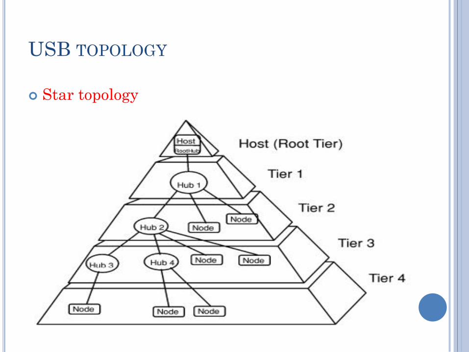
USB TOPOLOGY
Star topology

Host is responsible for powering the nodes if
there is no alternate power source.
Up to 127 devices can be attached to USB bus at
once.
It uses 4 shielded wires such that two are power
(+5v & GND) and The remaining two are twisted
pair differential data signals.
USB supports plug & play with dynamically
loadable and unloadable drivers.

The loading of the appropriate driver is done
using a PID/VID (Product ID/Vendor ID)
combination.
The VID is supplied by the USB Implementer's
forum.
Some organizations provide a extra VID for non-
commercial activities such as teaching, research.
USB supports Control, Interrupt, Bulk and
Isochronous transfers.
Data on the USB bus is transmitted LSb first.
Connection
?
?

All devices have an upstream connection to the
host or hub and all hosts and hubs have a
downstream connection to the device.
There are commonly two types of connectors,
called type A and type B which are shown below.
Type A plugs always face upstream and Type B
sockets are found on devices.
Type Mini was made for handheld devices (A&B).

USB uses a differential transmission pair for data.
This is encoded using NRZI and is bit stuffed to
ensure adequate transitions in the data stream.
The speed of USB bus is known by the applied voltage
on the bus using built in pull-up resistor.
A USB device will enter suspend state when there is
no activity on the bus for greater than 3.0 ms. It then
has a further 7 ms to shutdown the device.
so USB has a start of frame packet or keep alive sent
periodically on the bus. This prevents an idle bus
from entering suspend mode in the absence of data.

SUSPEND SORTS
Global Suspend
used when the entire USB bus enters suspend mode collectively.
Selective suspend
selected devices can be suspended by sending a command to the hub.
The device will resume operation when it receives any non idle signaling. If a device has remote wakeup enabled then it may signal to the host to resume from suspend.
Inside
?
?
USB

USB TRANSACTION Each one consists of :-
Token Packet (Header defining).
Optional Data Packet, (Containing the data payload).
Status Packet (Used to acknowledge transactions and to provide a means of error correction).
Because of the USB bus is a host centric bus. The host initiates all transactions.
The first packet, also called a token is generated by the host to describe what is to follow and whether the data transaction will be a read or write and what the device’s address and designated endpoint is.
The next packet is generally a data packet carrying the payload and is followed by an handshaking packet, reporting if the data or token was received successfully, or if the endpoint is stalled or not available to accept data.
Common
USB
Packet
? Field

SYNC
All packets must start with a sync field.
The sync field is 8 bits long at low and full speed
or 32 bits long for high speed and it may be
shorter.
It is used to synchronize the clock of the receiver
with that of the transmitter.
The last two bits indicate to the end of the SYNC
field and, by inference, the start of the PID

PID
PID stands for Packet Identifier and This field is
used to identify the type of packet that is being
sent.
There are 4 bits to the PID and to insure it is
received correctly, the 4 bits are complemented
and repeated, making an 8 bit PID in total. The
resulting format is shown below.
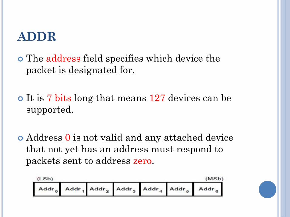
ADDR
The address field specifies which device the
packet is designated for.
It is 7 bits long that means 127 devices can be
supported.
Address 0 is not valid and any attached device
that not yet has an address must respond to
packets sent to address zero.
ENDP
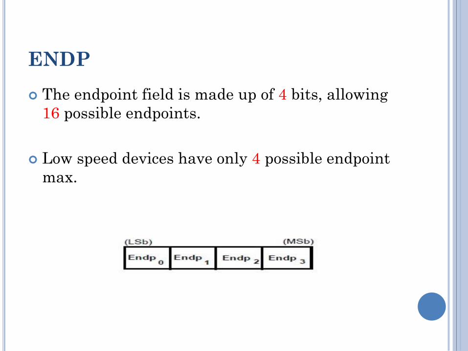
The endpoint field is made up of 4 bits, allowing
16 possible endpoints.
Low speed devices have only 4 possible endpoint
max.
FRAME NUMBER
Frame number is 11-bit field that is incremented
by the host on a per-frame.
Max number is 7FF H (2047).
It is sent only in SOF tokens at the start of each
frame.
DATA FIELD (PAYLOAD)
The data field may range from zero to 1024 bytes
and must be an integral number of bytes.
Data bits within each byte are shifted out LSb
first.
CRC
Cyclic Redundancy Checks are performed on the
data within the packet payload.
All token packets have a 5 bit CRC.
Data packets have a 16 bit CRC.
EOP
End of packet is Signaled by a Single Ended Zero
(SE0) for approximately 2 bit times followed by a
J for 1 bit time.

USB
Packets
Type
?
USB HAS FOUR DIFFERENT PACKET TYPES
Token packets - indicate the type of transaction
to follow.
Data packets - contain the payload.
Handshake packets - are used for
acknowledging data or reporting errors.
Start of frame packets - indicate the start of a
new frame.

TOKEN PACKETS
There are three types of token packets:-
In - Informs the USB device that the host wishes
to read information.
Out - Informs the USB device that the host wishes
to send information.
Setup - Used to begin control transfers.
Token Packets must conform to the following
format.

DATA PACKETS
There are two types of data packets each capable
of transmitting up to 1024 bytes of data.
DATA0
DATA1
High Speed mode defines another two data PIDs,
DATA2 and MDATA.
Data packets have the following format
DATA PACKETS (CON’T)
Maximum data payload size for low-speed devices
is 8 bytes.
Maximum data payload size for full-speed devices
is 1023 bytes.
Maximum data payload size for high-speed
devices is 1024 bytes.
Data must be sent in multiples of bytes (integral
number).

HANDSHAKE PACKETS
There are 3 types of handshake packets which
consist simply of the PID
ACK - Acknowledgment that the packet has been
successfully received.
NAK - Reports that the device temporary cannot
send/receive data. Also used during interrupt
transactions to inform the host there is no data to
send.
STALL - The device finds its in a state that it
requires intervention from the host.
Handshake Packets have the following format
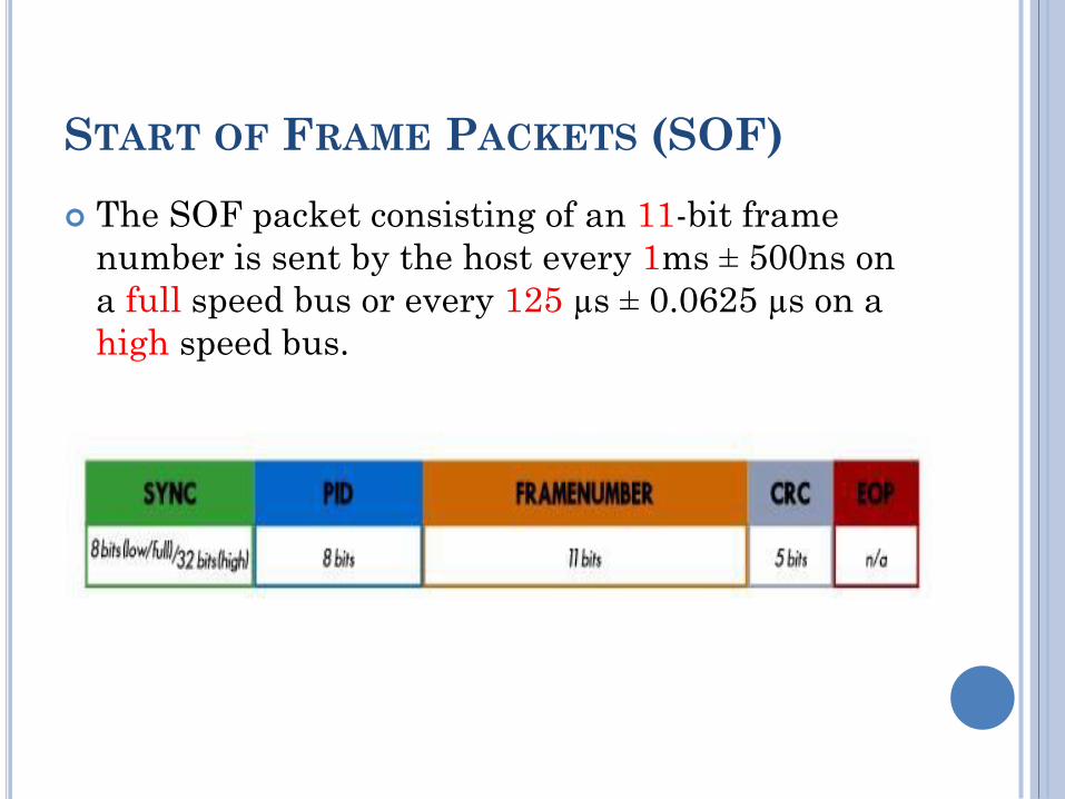
START OF FRAME PACKETS (SOF)
The SOF packet consisting of an 11-bit frame
number is sent by the host every 1ms ± 500ns on
a full speed bus or every 125 µs ± 0.0625 µs on a
high speed bus.
USB
Functions
?

USB devices which provide a capability or function such as a Printer, Zip Drive, Scanner, Modem or other peripheral called a function.
Most functions will have a series of buffers, Each buffer will belong to an endpoint - EP0 IN, EP0 OUT etc.
For example, the host sends a device descriptor request. The function hardware will read the setup packet and determine from the address field ,it will copy the payload of the following data packet to the appropriate endpoint buffer dedicated by the value in the endpoint field of the setup token.
It will then send a handshake packet to acknowledge the reception of the byte and generate an internal interrupt within the semiconductor/micro-controller for the appropriate endpoint signifying it has received a packet. This is typically all done in hardware.
The software now gets an interrupt, and should read the contents of the endpoint buffer and parse the device descriptor request.

USB
Endpoints
?

Endpoints can be described as sources or sinks of data.
Endpoints can also be seen as the interface between the hardware of the function device and the firmware running on the function device.
For example, data is flowing out from the host, it will end up in the EP1 OUT buffer. Your firmware will then read this data. If it wants to return data, the function cannot simply write to the bus as the bus is controlled by the host. Therefore it writes data to EP1 IN which sits in the buffer until such time when the host sends a IN packet to that endpoint requesting the data.
All devices must support endpoint zero. This is the endpoint which receives all of the devices control and status requests during enumeration and if the device not yet has an address.
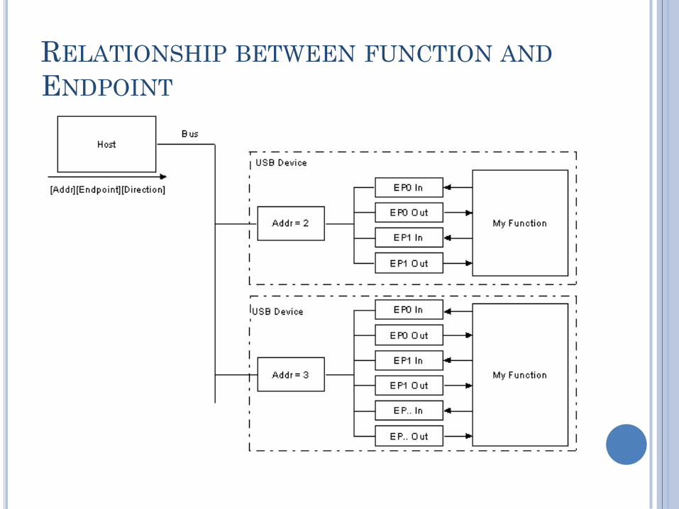
RELATIONSHIP BETWEEN FUNCTION AND
ENDPOINT
USB
Pipes
?
While the device sends and receives data on a
series of endpoints, the client software transfers
data through pipes.
A pipe is a logical connection between the host
and endpoint(s).
Pipes will also have a set of parameters
associated with them such as:
Bandwidth allocated to it.
Transfer type (Control, Bulk, Isochronous or
Interrupt) it uses,
Direction of data flow.
maximum packet/buffer sizes.
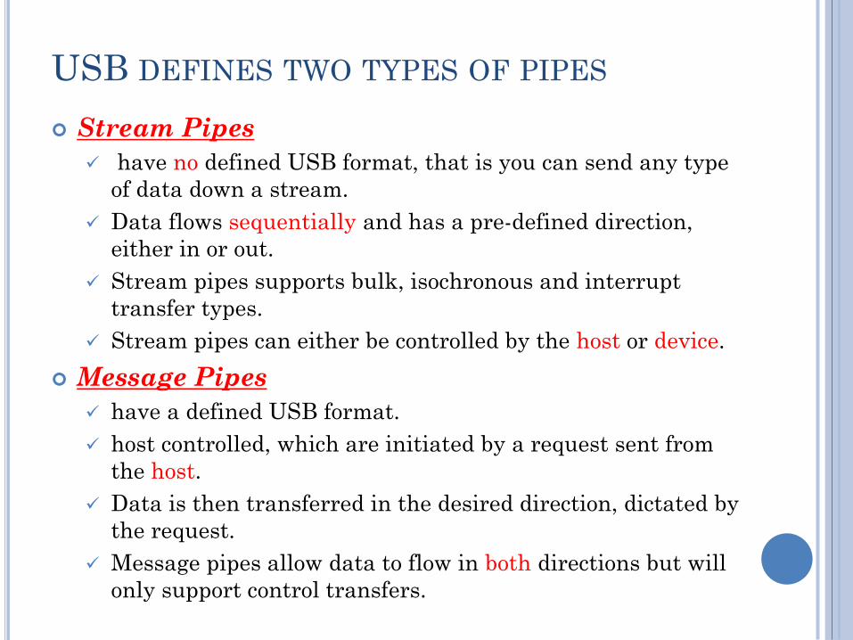
USB DEFINES TWO TYPES OF PIPES
Stream Pipes
have no defined USB format, that is you can send any type
of data down a stream.
Data flows sequentially and has a pre-defined direction,
either in or out.
Stream pipes supports bulk, isochronous and interrupt
transfer types.
Stream pipes can either be controlled by the host or device.
Message Pipes
have a defined USB format.
host controlled, which are initiated by a request sent from
the host.
Data is then transferred in the desired direction, dictated by
the request.
Message pipes allow data to flow in both directions but will
only support control transfers.

Endpoints
Types
?
Interrupt
Transfers
Bulk
Transfers
Isochronous
Transfers
Control
Transfers

CONTROL TRANSFERS
Control transfers are typically used for command
and status operations.
They are essential to setup a USB device with all
enumeration functions being performed using
control transfers.
They are typically bursty, initiated by the host
and use best effort delivery.
The packet length of control transfers in low
speed devices must be 8 bytes, high speed devices
allow a packet size of 8, 16, 32 or 64 bytes and
full speed devices must have a packet size of 64
bytes.

Control
Transfer
?
setup
Status
Data

1- SETUP STAGE
Held when the request is sent.
consists of three packets.
The setup token is sent first which contains the address and endpoint number.
The data packet is sent next and always has a PID type of DATA0 and includes a setup packet which details the type of request.
The last packet is a handshake used for acknowledging successful receipt or to indicate an error.
If the function successfully receives the setup data (CRC and PID etc OK) it responds with ACK, otherwise it ignores the data and doesn’t send a handshake packet.
Functions cannot issue a STALL or NAK packet in response to a setup packet.
2- DATA STAGE
Optional and consists of one or multiple IN or
OUT transfers.
The setup request indicates the amount of data
to be transmitted in this stage, If it exceeds the
maximum packet size, data will be sent in
multiple transfers each being the maximum
packet length except for the last packet.
Data stage has two different scenarios depending
upon the direction of data transfer (IN / OUT).

IN-TRANSFER
When the host is ready to receive control data it
issues an IN Token.
If the function receives the IN token with an
error e.g. the PID doesn't match the inverted PID
bits, then it ignores the packet.
If the token was received correctly, the device can
either reply with a DATA packet containing the
control data to be sent, a stall packet indicating
the endpoint cannot send and needs help or a
NAK packet indicating to the host that the
endpoint is working, but temporarily has no data
to send.
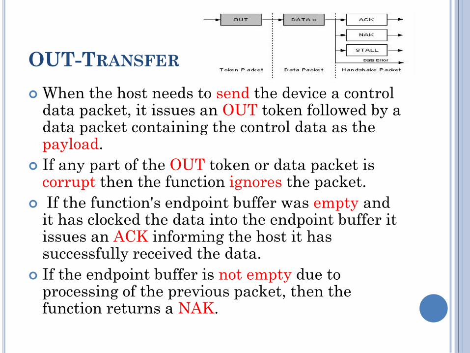
OUT-TRANSFER
When the host needs to send the device a control data packet, it issues an OUT token followed by a data packet containing the control data as the payload.
If any part of the OUT token or data packet is corrupt then the function ignores the packet.
If the function's endpoint buffer was empty and it has clocked the data into the endpoint buffer it issues an ACK informing the host it has successfully received the data.
If the endpoint buffer is not empty due to processing of the previous packet, then the function returns a NAK.

3- STATUS STAGE
reports the status of the overall request and this once again varies due to direction of transfer.
Status reporting is always performed by the function.
IN: If the host sent IN token(s) during the data stage to receive data, then the host must acknowledge the successful receipt of this data.
This is done by the host sending an OUT token followed by a zero length data packet.
The function can now report its status in the handshaking stage.
An ACK indicates the function has completed the command is now ready to accept another command. If an error occurred during the processing of this command, then the function will issue a STALL.

OUT: If the host sent OUT token(s) during the
data stage to transmit data, the function will
acknowledge the successful receipt of data by
sending a zero length packet in response to an IN
token.
However if an error occurred, it should issue a
STALL or if it is still busy processing data, it
should issue a NAK asking the host to retry the
status phase later.

Example
?
THE HOST WANTS TO REQUEST A
DEVICE DESCRIPTOR DURING
ENUMERATION

PROCEDURE
The host will send the Setup token telling the
function that the following packet is a Setup packet.
The Address field will hold the address of the device
which the host is requesting the descriptor from.
The endpoint number should be zero, specifying the
default pipe.
The host will then send a DATA0 packet. This will
have an 8 byte payload which is the Device Descriptor
Request (Low Speed).
The USB function then acknowledges the setup
packet has been read correctly with no errors.
If the packet was received corrupt, the device just
ignores this packet and The host will then resend the
packet after a short delay
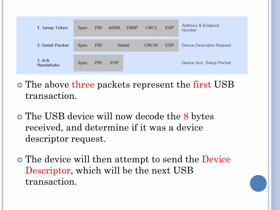
The above three packets represent the first USB
transaction.
The USB device will now decode the 8 bytes
received, and determine if it was a device
descriptor request.
The device will then attempt to send the Device
Descriptor, which will be the next USB
transaction.

DATA STAGE
In this case, we assume that the maximum
payload size is 8 bytes.
The host sends the IN token, telling the device it
can now send data for this endpoint.
As the maximum packet size is 8 bytes, we must
split up the 12 byte device descriptor into chunks
to send, Each chunk must be 8 bytes except for
the last transaction.
The host acknowledges every data packet we
send it.

DATA STAGE (CON’T)
STATUS STAGE
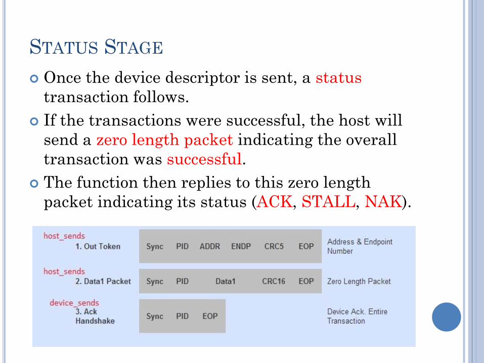
Once the device descriptor is sent, a status
transaction follows.
If the transactions were successful, the host will
send a zero length packet indicating the overall
transaction was successful.
The function then replies to this zero length
packet indicating its status (ACK, STALL, NAK).

Interrupt
Transfer
?
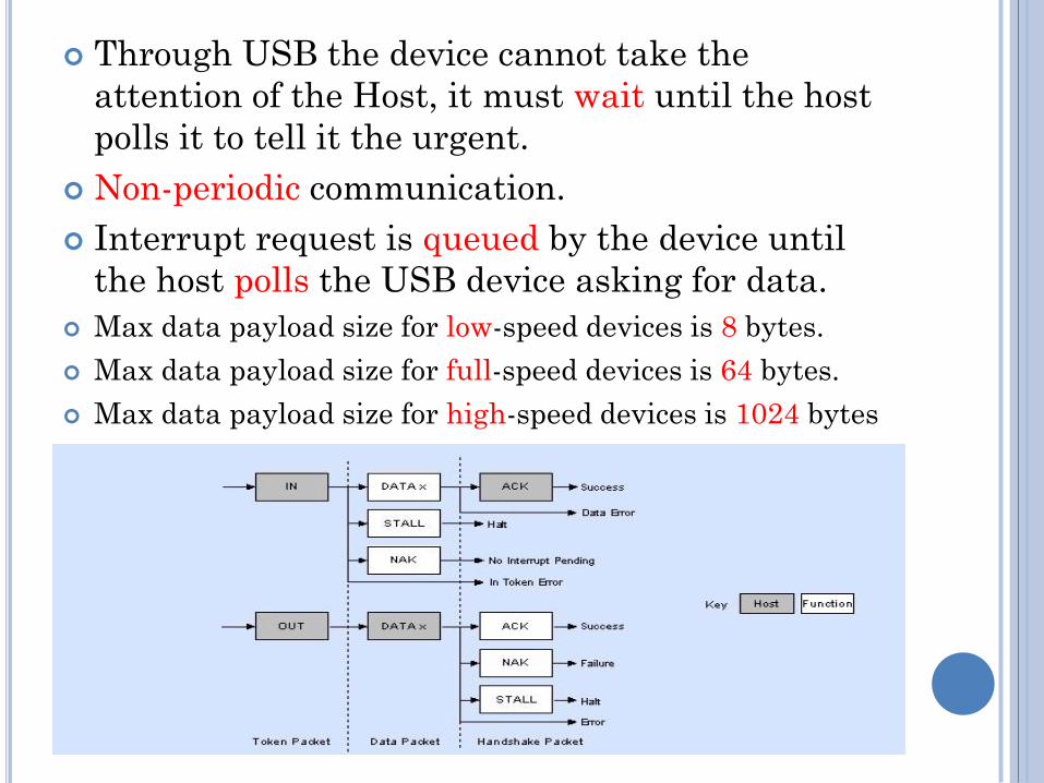
Through USB the device cannot take the
attention of the Host, it must wait until the host
polls it to tell it the urgent.
Non-periodic communication.
Interrupt request is queued by the device until
the host polls the USB device asking for data.
Max data payload size for low-speed devices is 8 bytes.
Max data payload size for full-speed devices is 64 bytes.
Max data payload size for high-speed devices is 1024 bytes

Isochronous
Transfer
?
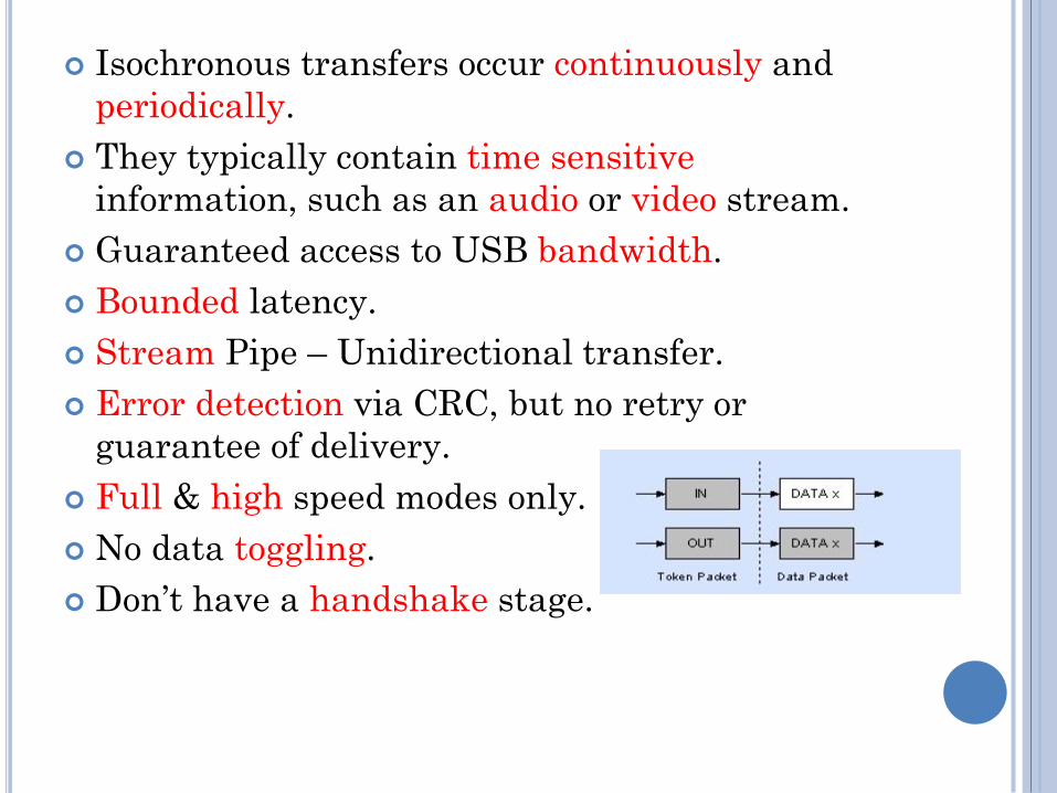
Isochronous transfers occur continuously and
periodically.
They typically contain time sensitive
information, such as an audio or video stream.
Guaranteed access to USB bandwidth.
Bounded latency.
Stream Pipe – Unidirectional transfer.
Error detection via CRC, but no retry or
guarantee of delivery.
Full & high speed modes only.
No data toggling.
Don’t have a handshake stage.

Bulk
Transfer
?

can be used for large bursty data, Such as print-job sent to a printer or an image generated from a scanner.
It provides error correction in the form of a CRC16 field on the data payload and error detection/re-transmission mechanisms ensuring data is transmitted and received without error.
Bulk transfers will use spare un-allocated bandwidth on the bus.
It should only be used for time insensitive communication as there is no guarantee of latency.
only supported by full and high speed devices.
For full speed endpoints, max bulk packet size is 8, 16, 32 or 64 bytes long.
For high speed endpoints, max packet size can be up to 512 bytes long.
If the data payload falls short of the maximum packet size, it doesn't need to be padded with zeros.
Bandwidth
Management
?

The host is responsible for managing the bandwidth of the bus.
This is done at enumeration when configuring Isochronous and Interrupt Endpoints and throughout the operation of the bus (if found).
no more than 90% of any frame to be allocated for periodic transfers (Interrupt and Isochronous) on a full speed bus.
On high speed buses this limitation gets reduced to no more than 80% of a micro-frame can be allocated for periodic transfers.
So you can quite quickly see that if you have a highly saturated bus with periodic transfers, the remaining 10% is left for control transfers and once those have been allocated, bulk transfers will get their slice of what is left.
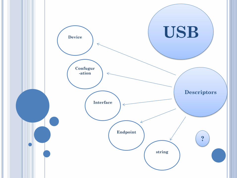
USB
Descriptors
?
Interface
string
Endpoint
Confugur
-ation
Device

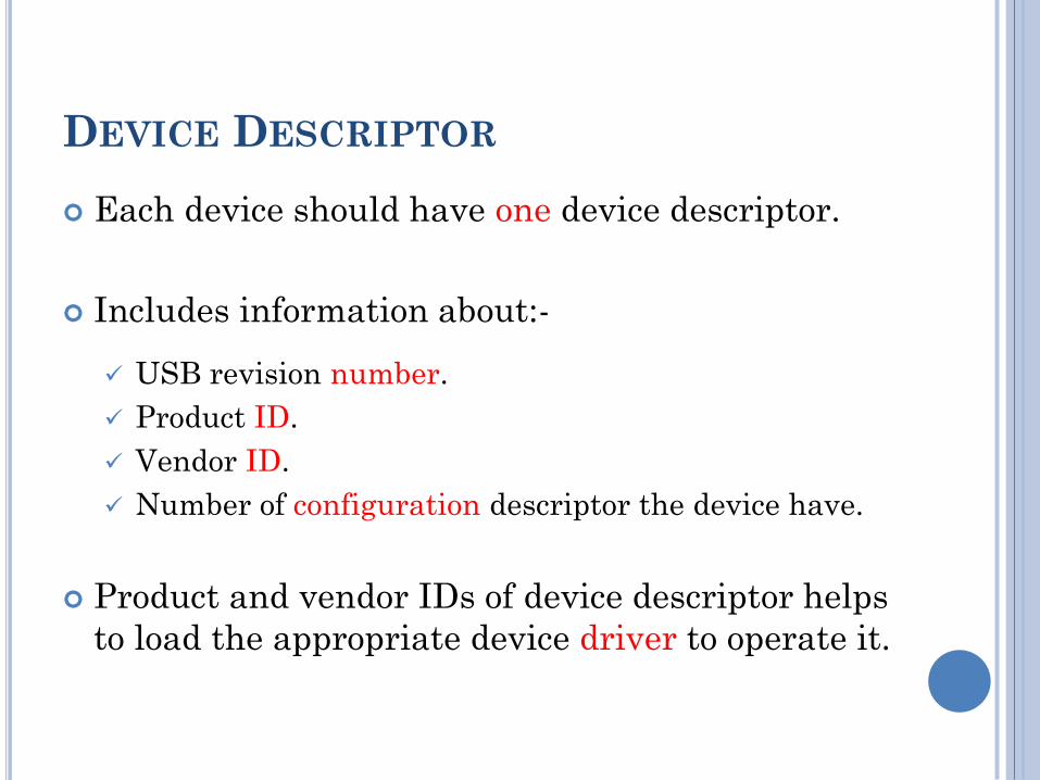
DEVICE DESCRIPTOR
Each device should have one device descriptor.
Includes information about:-
USB revision number.
Product ID.
Vendor ID.
Number of configuration descriptor the device have.
Product and vendor IDs of device descriptor helps
to load the appropriate device driver to operate it.

CONFIGURATION DESCRIPTOR
The configuration descriptor specifies values such as the amount of power this particular configuration uses.
if the device is self or bus powered and the number of interfaces it has.
When a device is enumerated, the host reads the device descriptors and can make a decision of which configuration to enable.
It can only enable one configuration at a time.
changing the configuration requires all activity on each endpoint to stop.
very few devices have more than 1 configuration.
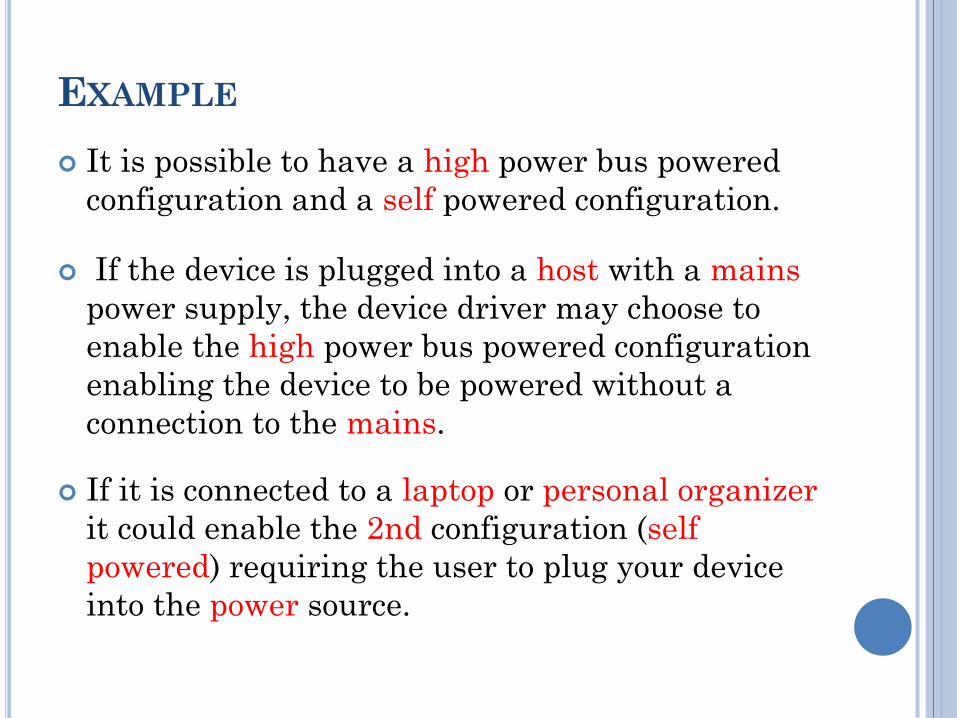
EXAMPLE
It is possible to have a high power bus powered
configuration and a self powered configuration.
If the device is plugged into a host with a mains
power supply, the device driver may choose to
enable the high power bus powered configuration
enabling the device to be powered without a
connection to the mains.
If it is connected to a laptop or personal organizer
it could enable the 2nd configuration (self
powered) requiring the user to plug your device
into the power source.

INTERFACE DESCRIPTOR
could be seen as a header or grouping of the endpoints into a functional group performing a single feature of the device.
For example you could have a multi-function fax/scanner/printer device.
Interface descriptor 1 describe the endpoints of the fax function.
Interface descriptor 2 the scanner function.
Interface descriptor 3 the printer function.
Unlike the configuration descriptor, there is no limitation to having only one interface enabled at a time.
A device could have 1 or more interface descriptors enabled at once.

Interface descriptors have a bInterfaceNumber field specifying the Interface number and a bAlternateSetting which allows an interface to change settings on the fly.
For example we could have a device with two interfaces, interface 1 and interface 2.
Interface 1 has bInterfaceNumber = 0, bAlternateSetting = 0 (default).
Interface 2 has bInterfaceNumber = 0, bAlternateSetting = 0 (default).
Making bAlternateSetting = 1 means making an alternate settings to be applied on the configuration.
In other words, having two configurations, in that we can be transmitting data over interface zero while we change the endpoint settings associated with interface one without affecting interface zero.
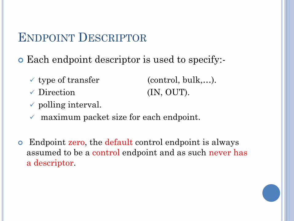
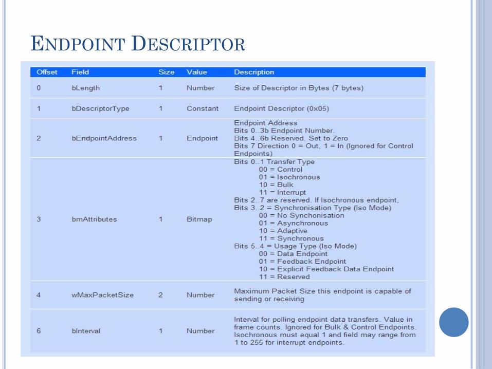
ENDPOINT DESCRIPTOR
Each endpoint descriptor is used to specify:-
type of transfer (control, bulk,…).
Direction (IN, OUT).
polling interval.
maximum packet size for each endpoint.
Endpoint zero, the default control endpoint is always
assumed to be a control endpoint and as such never has
a descriptor.

Composition
OF
Descriptors
?
USB
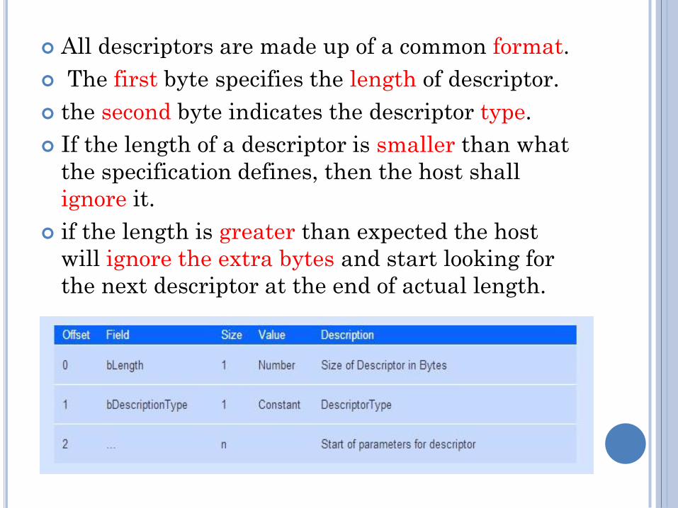
All descriptors are made up of a common format.
The first byte specifies the length of descriptor.
the second byte indicates the descriptor type.
If the length of a descriptor is smaller than what
the specification defines, then the host shall
ignore it.
if the length is greater than expected the host
will ignore the extra bytes and start looking for
the next descriptor at the end of actual length.

DEVICE DESCRIPTOR

CONFIGURATION DESCRIPTOR

INTERFACE DESCRIPTOR
ENDPOINT DESCRIPTOR

STRING DESCRIPTORS
provide optional human readable information.
If they are not used, any string index fields of
descriptors must be set to zero.
The strings are encoded in the Unicode format and
products can be made to support multiple languages.
A list of USB Language IDs can be found in USB
Language Identifiers (LANGIDs) on USB.org.
The host should read this descriptor to determine
what languages are available.
If a language is supported, it can then be referenced
by sending the language ID in the wIndex field of
a Get Descriptor(String) request.
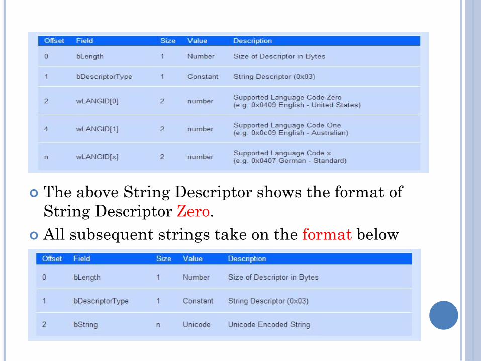
The above String Descriptor shows the format of
String Descriptor Zero.
All subsequent strings take on the format below

Requests
USB
?

Setup
Packet
?

Every USB device must respond to setup packets
on the default pipe.
The setup packets are used for detection and
configuration of the device and carry out common
functions such as setting the USB device’s
address, requesting a device descriptor or checking
the status of a endpoint.
A USB compliant Host expects all requests to be
processed within a maximum period of 5 seconds.
Standard Device requests without a data stage
must be completed in 50 ms.
Standard Device requests with a data stage must
start to return data 500 ms after the request.

Each data packet must be sent within 500 ms of
the successful transmission of the previous
packet.
The status stage must complete within 50 ms
after the transmission of the last data packet.
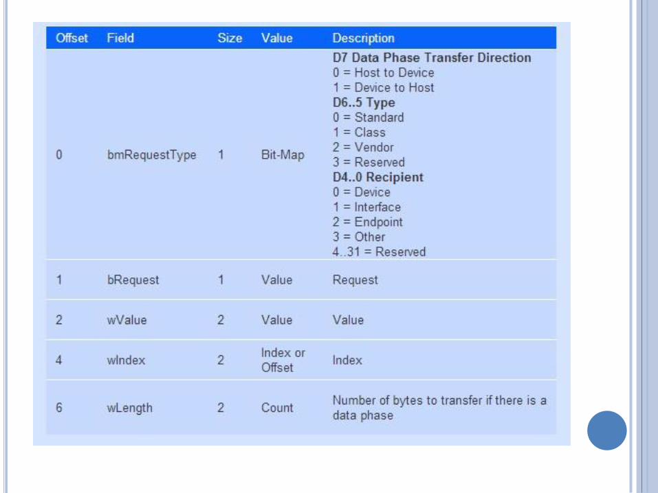
Each request starts with a 8 byte long Setup data
Packet which has the following format
Standard
device
requests
?
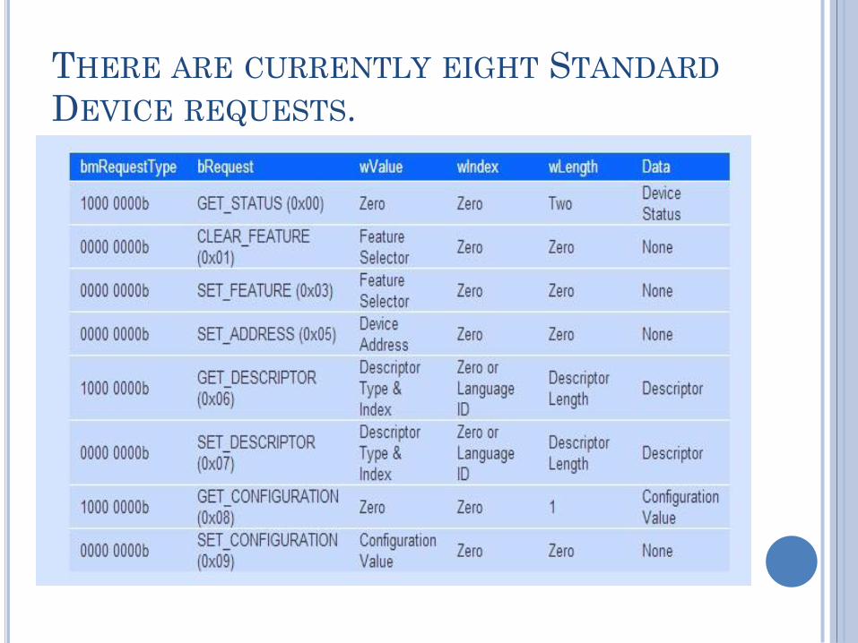
THERE ARE CURRENTLY EIGHT STANDARD
DEVICE REQUESTS.
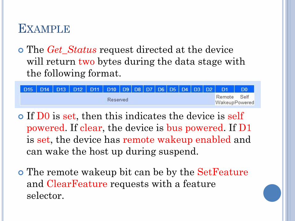
EXAMPLE
The Get_Status request directed at the device
will return two bytes during the data stage with
the following format.
If D0 is set, then this indicates the device is self
powered. If clear, the device is bus powered. If D1
is set, the device has remote wakeup enabled and
can wake the host up during suspend.
The remote wakeup bit can be by the SetFeature
and ClearFeature requests with a feature
selector.
Set_Address is used during enumeration to
assign a unique address to the USB device.
The address is specified in wValue and can only
be a maximum of 127. This request is unique in
that the device does not set its address until after
the completion of the status stage.
This request is unique in that the device does not
set its address until after the completion of the
status stage, but All other requests must
complete before the status stage.
Set_Descriptor/Get_Descriptor is used to
set/return the specified descriptor in wValue.
Get_Configuration/Set_Configuration is used to
request or set/return the current device
configuration.
Standard
interface
requests
?
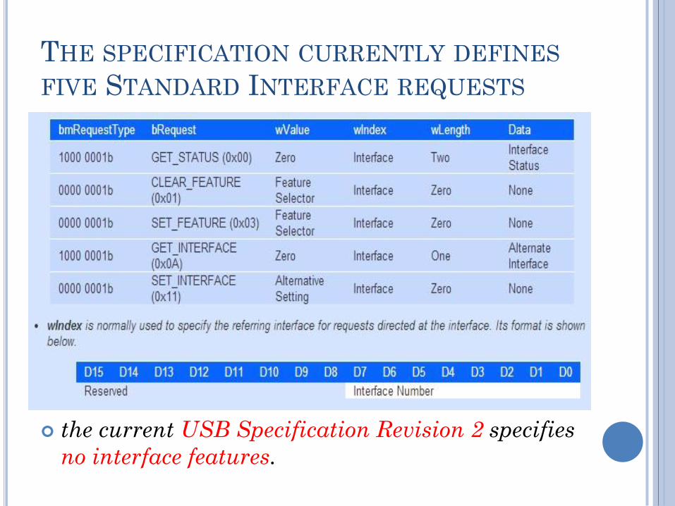
THE SPECIFICATION CURRENTLY DEFINES
FIVE STANDARD INTERFACE REQUESTS
the current USB Specification Revision 2 specifies
no interface features.

Standard
Endpoints
requests
?


Enumeration
Steps
?

1. The system has a new device.
2. The hub detects the device
3. The host learns of the new device.
4. The hub detects whether a device is low or full speed.
5. The hub resets the device.
6. The host learns if a full-speed device supports high speed.
7. The hub establishes a signal path between the device and the bus.
8. The host sends a Get Descriptor request to learn the maximum packet size of the default pipe.
9. The host assigns an address.
10. The host learns about the device’s abilities.
11. The host assigns and loads a device driver (client).
12. The host’s device driver selects a configuration.

REFERENCES
Universal Serial Bus Specification 2.0.
Wikipedia.
www.usb.org.
beyondlogic.org.
USB Overview by Silicon Labs.

CONTACT DETAILS
Mostafa El-koumy
Embedded SW Developer
Related Documents