eScholarship provides open access, scholarly publishing services to the University of California and delivers a dynamic research platform to scholars worldwide. Lawrence Berkeley National Laboratory Lawrence Berkeley National Laboratory Title: U.S. Heavy Ion Beam Science towards inertial fusion energy Author: Logan, B.G. Baca, D. Barnard, J.J. Bieniosek, F.M. Burkhart, C. Celata, C.M. Chacon-Golcher, E. Cohen, R.H. Davidson, R.C. Efthimion, P. Faltens, A. Friedman, A. Grisham, L. Grote, D.P. Haber, I. Henestroza, E. Kaganovich, I. Kishek, R.A. Kwan, J.W. Lee, E.P. Lee, W.W. Leitner, M. Lund, S.M. Meier, W.R. Molvik, A.W. O'Shea, P.G. Olson, C. Olson, R.E. Prost, L.R. Qin, H. Reiser, M. Rose, D. Sabbi, G. Seidl, P.A. Sharp, W.M. Shuman, D.B. Vay, J.-L. Waldron, W.L. Welch, D. Westenskow, G.A. Yu, S.S. Publication Date: 10-01-2002

Welcome message from author
This document is posted to help you gain knowledge. Please leave a comment to let me know what you think about it! Share it to your friends and learn new things together.
Transcript
eScholarship provides open access, scholarly publishingservices to the University of California and delivers a dynamicresearch platform to scholars worldwide.
Lawrence Berkeley National LaboratoryLawrence Berkeley National Laboratory
Title:U.S. Heavy Ion Beam Science towards inertial fusion energyAuthor:Logan, B.G.Baca, D.Barnard, J.J.Bieniosek, F.M.Burkhart, C.Celata, C.M.Chacon-Golcher, E.Cohen, R.H.Davidson, R.C.Efthimion, P.Faltens, A.Friedman, A.Grisham, L.Grote, D.P.Haber, I.Henestroza, E.Kaganovich, I.Kishek, R.A.Kwan, J.W.Lee, E.P.Lee, W.W.Leitner, M.Lund, S.M.Meier, W.R.Molvik, A.W.O'Shea, P.G.Olson, C.Olson, R.E.Prost, L.R.Qin, H.Reiser, M.Rose, D.Sabbi, G.Seidl, P.A.Sharp, W.M.Shuman, D.B.Vay, J.-L.Waldron, W.L.Welch, D.Westenskow, G.A.Yu, S.S.Publication Date:10-01-2002

eScholarship provides open access, scholarly publishingservices to the University of California and delivers a dynamicresearch platform to scholars worldwide.
Publication Info:Lawrence Berkeley National Laboratory
Permalink:http://escholarship.org/uc/item/0tj0f4j7
IAEA-OV/3-41
U.S. Heavy Ion Beam Science towards Inertial Fusion Energy
B.G. Logan 1), D. Baca 1), J.J. Barnard 2), F.M. Bieniosek 1), C. Burkhart 6), C.M. Celata1), E. Chacon-Golcher 1), R.H. Cohen 2), R.C. Davidson 3), P. Efthimion 3), A. Faltens 1),A. Friedman 2), L. Grisham 3), D.P Grote 2), I. Haber 4), E. Henestroza 1), I. Kaganovich3), R.A. Kishek 4), J.W. Kwan 1), E.P. Lee 1), W.W. Lee 3), M. Leitner 1), S.M. Lund 2),W.R. Meier 2), A.W. Molvik 2), P.G. O’Shea 4), C. Olson 8), R.E. Olson 7), L.R. Prost 1),H. Qin 3), M. Reiser 4), D. Rose 5), G. Sabbi 1), P.A Seidl 1), W.M. Sharp 2), D.B. Shuman1), J-L. Vay 1), W.L. Waldron 1), D. Welch 5), G.A. Westenskow 2), S.S. Yu 1)
1) Lawrence Berkeley National Laboratory, Berkeley, CA2) Lawrence Livermore National Laboratory, Livermore, CA3) Princeton Plasma Physics Laboratory, Princeton, NJ4) University of Maryland, College Park, MD5) Mission Research Corporation, Albuquerque, NM6) First Point Scientific, Inc., Agoura Hills, CA7) University of Missouri, Rolla, MO8) Sandia National Laboratory, Albuquerque, NM
Email contact of main author: [email protected]
Abstract. Significant experimental and theoretical progress in the U.S heavy-ion fusion (HIF) program is
reported in modeling and measurements of intense space-charge-dominated heavy ion and electron beams.
Measurements of the transport of a well-matched and aligned high current (0.2A) 1.0 MeV potassium ion beam
through 10 electric quadrupoles, with a fill factor of 60%, shows no emittance growth within experimental
measurement uncertainty, as expected from the simulations. Another experiment shows that passing a beam
through an aperture can reduce emittance to near the theoretical limits, and that plasma neutralization of the
beam’s space-charge can greatly reduce the focal spot radius. Measurements of intense beamlet current density,
emittance, charge-state purity, and energy spread from a new, high-brightness, Argon plasma source for HIF
experiments are described. New theory and simulations of neutralization of intense beam space charge with
plasma in various focusing chamber configurations indicate that near-emittance-limited beam focal spot sizes
can be obtained even with beam perveance an order of magnitude higher than in earlier HIF focusing
experiments.
1. Introduction
This article reports results from the last two years of experiments and simulations with space-charge-dominated heavy ion and electron beams relevant to understanding the behavior of thehigh-brightness heavy ion beams ultimately required to drive high-gain inertial fusion targets.The success of inertial fusion energy (IFE) with heavy ions will require high-brightness andpeak power accelerators [1], high-gain target designs [2], methods to produce, and inject suchtargets at 5 Hz pulse rates and targets that can be mass produced at low cost [3], and long-lasting, low-activation chambers that can protect the walls and focusing magnets fromrepeated fusion energy bursts [3]. Heavy ion beam research is carried out under the auspicesof the Heavy-Ion Fusion Virtual National Laboratory (HIF-VNL) by Lawrence BerkeleyNational Laboratory, Lawrence Livermore National Laboratory, and Princeton PlasmaPhysics Laboratory, and other HIF beam science research is performed by the University of
IAEA-OV/3-42
Maryland, the Naval Research Laboratory, Mission Research Corporation, and the Universityof Missouri.
Heavy Ion Fusion is attractive for Inertial Fusion Energy because high energy accelerators ofMJ range beam energies potentially have the required efficiencies, pulse rates, and durability,and because clear-bore magnets used to focus heavy ions can avoid line-of-sight target debrisand radiation. Transporting and focusing space-charge dominated beams with 0.1 to 10 µC/msuitable for Inertial Fusion Energy is the main new challenge. Particle-in-cell simulations arein good agreement with the results of past low current (mA level) beam experiments intransport, merging, acceleration and final focus, in which the dimensionless beam perveances(space-charge potential/ion kinetic energy) had driver-scale values. Here, we report initialresults on three new experiments at high currents (>10x larger) and large tune depressions,where kV-level space-charge potentials can attract and sometimes trap stray electrons andtherefore affect transport: the High Current Experiment (HCX), which studies transport ofsuch beams and interaction with gas and electrons (Sec. 2); beam production by highbrightness plasma sources (Sec. 3); and ballistic focusing with plasma neutralization in theNeutralized Transport Experiment (NTX) (Sec. 4). The University of Maryland also performsexperiments and simulations with electron beams with perveances relevant to heavy ionfusion (Sec. 5). Supporting theory/simulation for the HIF-VNL is described in Sec. 6. Finally,a brief summary of future plans is given in Sec. 7.
2. The High Current Experiment (HCX)
The High Current Experiment (HCX), located at Lawrence Berkeley National Laboratory andcarried out by the HIF-VNL, is designed to explore the physics of intense beams with line-charge density of about 0.2 µC/m and pulse duration 4<τ<10 µs, close to the values ofinterest for a fusion driver [4]. Experiments are performed near driver injection energy (1-1.8MeV). HCX beam transport is at present based mainly on electrostatic quadrupole focusing,which provides the most efficient option at low energy and provides clearing fields to removeunwanted electrons. However, magnetic transport experiments will also be performed toexplore limitations associated with magnetic focusing, in particular, the onset of transport-limiting effects due to electrons trapped in the space-charge potential of the ion beam. Theprincipal initial effort on the HCX (see FIG.1. below) has been experiments carried out with amatched and well-aligned K+ ion beam transported through 10 electrostatic quadrupoles. Themain scientific results to date are:
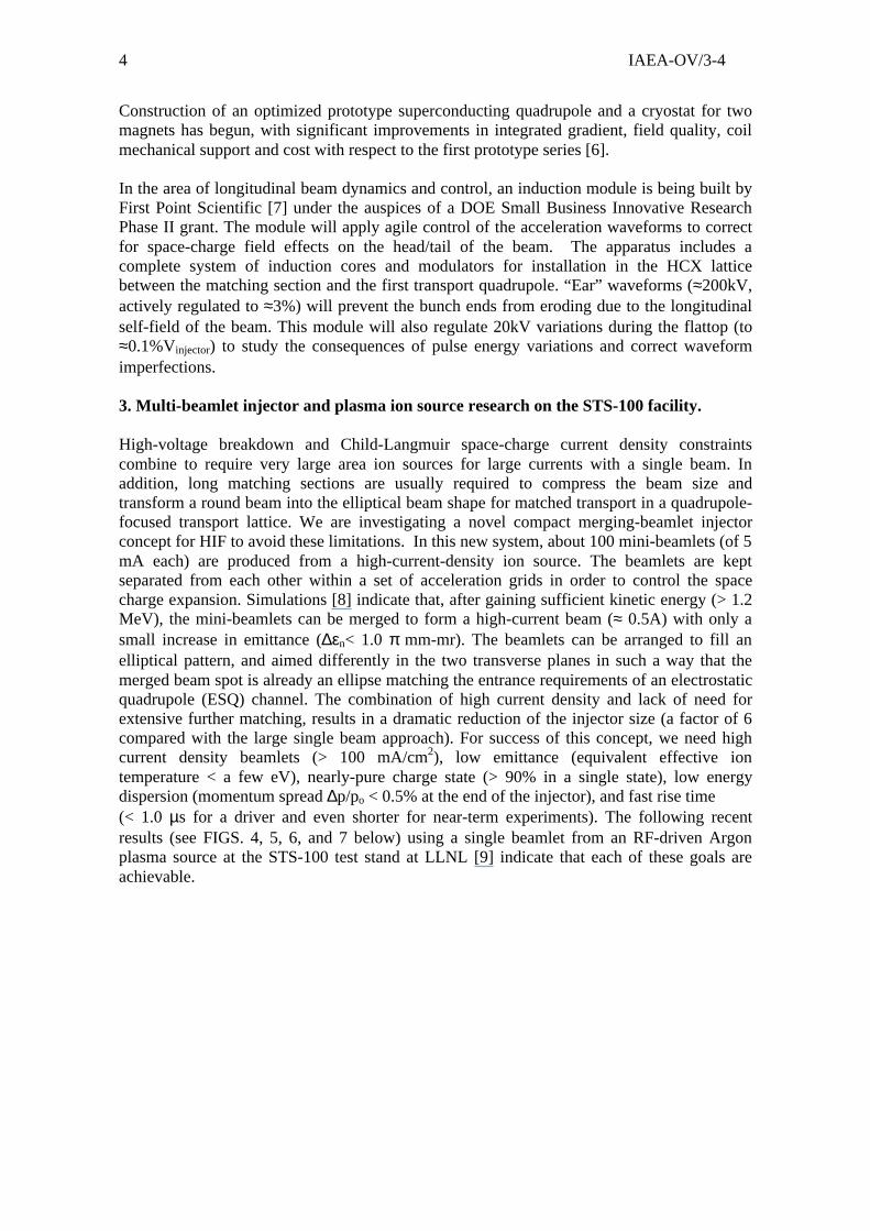
• There is no emittance growth ( n = 0.6 ±20%( )mm − mrad ) within diagnosticsensitivity, and little beam loss (< 2% in the middle of the beam pulse), as expectedfrom initial particle simulations. See FIG. 2 below showing the beam envelope (x andy vs z) through the 10 quad transport region between QD1 and the end diagnosticstation (D-end) in FIG. 1 below. The beam centroid is aligned to < 0.5 mm and 2 mr ofthe central axis of the channel, with envelope mismatch amplitude ≈ ±1.0mm.
• A long-life, alumino-silicate source of improved surface uniformity has replaced acontact-ionization source, eliminating depletion-induced experimental uncertainties.
• Significant differences between the experimental data and early theoreticalcalculations of the beam envelope propagating through the electrostatic quadrupoleswere encountered. More detailed envelope models and simulations have resolved mostof the discrepancy, and achievable limits on envelope predictability and control arebeing probed.
IAEA-OV/3-43
• The experimental current density distribution, J(x,y), and phase-space data are beingused to initialize high-resolution simulations to enable realistic modeling and detailedcomparisons with experiment. New methods have been derived for projecting the full4-D phase space from experimental measurements, and the resulting distributions arebeing used in high-resolution PIC simulations of the experiment.
• Considerable progress has been made in the development of new time-resolved phase-space diagnostics, which will speed up data acquisition in this and other upcomingbeam experiments in the HIF-VNL.
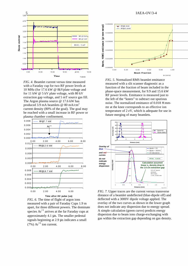
• A new Gas and Electron Source Diagnostic (GESD) has made preliminarymeasurements of the secondary electron coefficient. The secondary emission yieldvaries as cos-1(θ), as predicted theoretically (see FIG. 3. below). Data from the GESDwill be relevant to upcoming experiments on gas, particle loss and electron effects in amagnetic quadrupole lattice.
A beam line of four pulsed magnetic quadrupoles, instrumented with diagnostics to measurethe production and energy of trapped electrons, secondary atoms and ions is being installeddownstream of the 10 electrostatic quads [5].
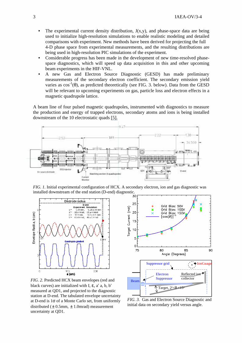
FIG. 1. Initial experimental configuration of HCX. A secondary electron, ion and gas diagnostic wasinstalled downstream of the end station (D-end) diagnostic.
FIG. 2. Predicted HCX beam envelopes (red and black curves) are initialized with I, ε, a′ a, b, b′ measured at QD1, and projected to the diagnostic station at D-end. The tabulated envelope uncertainty at D-end is 1σ of a Monte Carlo set, from uniformly distributed (± 0.5mm, ± 1.0mrad) measurement uncertainty at QD1.
IonGuage
Target, 2o<θ <15o
Reflected ioncollector
ElectronSuppressor
Beam
Suppressor grid
FIG. 3. Gas and Electron Source Diagnostic andinitial data on secondary yield versus angle.
IAEA-OV/3-44
Construction of an optimized prototype superconducting quadrupole and a cryostat for twomagnets has begun, with significant improvements in integrated gradient, field quality, coilmechanical support and cost with respect to the first prototype series [6].
In the area of longitudinal beam dynamics and control, an induction module is being built byFirst Point Scientific [7] under the auspices of a DOE Small Business Innovative ResearchPhase II grant. The module will apply agile control of the acceleration waveforms to correctfor space-charge field effects on the head/tail of the beam. The apparatus includes acomplete system of induction cores and modulators for installation in the HCX latticebetween the matching section and the first transport quadrupole. “Ear” waveforms (≈200kV,actively regulated to ≈3%) will prevent the bunch ends from eroding due to the longitudinalself-field of the beam. This module will also regulate 20kV variations during the flattop (to≈0.1%Vinjector) to study the consequences of pulse energy variations and correct waveformimperfections.
3. Multi-beamlet injector and plasma ion source research on the STS-100 facility.
High-voltage breakdown and Child-Langmuir space-charge current density constraintscombine to require very large area ion sources for large currents with a single beam. Inaddition, long matching sections are usually required to compress the beam size andtransform a round beam into the elliptical beam shape for matched transport in a quadrupole-focused transport lattice. We are investigating a novel compact merging-beamlet injectorconcept for HIF to avoid these limitations. In this new system, about 100 mini-beamlets (of 5mA each) are produced from a high-current-density ion source. The beamlets are keptseparated from each other within a set of acceleration grids in order to control the spacecharge expansion. Simulations [8] indicate that, after gaining sufficient kinetic energy (> 1.2MeV), the mini-beamlets can be merged to form a high-current beam (≈ 0.5A) with only asmall increase in emittance (∆εn< 1.0 π mm-mr). The beamlets can be arranged to fill anelliptical pattern, and aimed differently in the two transverse planes in such a way that themerged beam spot is already an ellipse matching the entrance requirements of an electrostaticquadrupole (ESQ) channel. The combination of high current density and lack of need forextensive further matching, results in a dramatic reduction of the injector size (a factor of 6compared with the large single beam approach). For success of this concept, we need highcurrent density beamlets (> 100 mA/cm2), low emittance (equivalent effective iontemperature < a few eV), nearly-pure charge state (> 90% in a single state), low energydispersion (momentum spread ∆p/po < 0.5% at the end of the injector), and fast rise time(< 1.0 µs for a driver and even shorter for near-term experiments). The following recentresults (see FIGS. 4, 5, 6, and 7 below) using a single beamlet from an RF-driven Argonplasma source at the STS-100 test stand at LLNL [9] indicate that each of these goals areachievable.
IAEA-OV/3-45
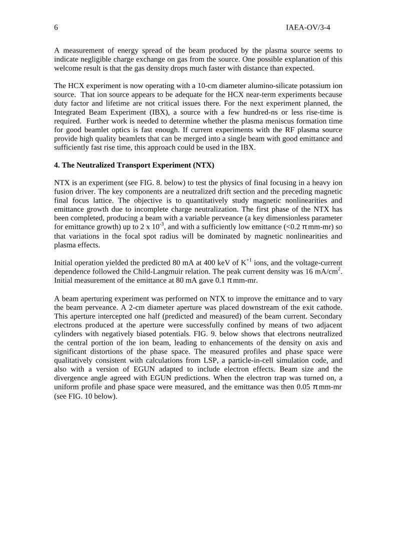
FIG. 6. The time of flight of argon ionsmeasured with a pair of Faraday Cups 1.9 mapart, for three different powers. The dominatespecies Ar+1 arrives at the far Faraday cups atapproximately 4.1 µs. The smaller pedestalsignals beginning at 2.9 µs indicates a small(7%) Ar+2 ion current.
-10
0
10
20
30
40
50
0 2 4 6 8
Distance (mm)
Dipole=0VDipole=3000V
0
10
20
30
40
50
-1 -0.5 0 0.5 1 1.5 2
Distance (mm)
dipole = 0Vdipole = 3000VCX Calculation
8.0 mT source pressure Error bars:1 mV, 0.025 mm
Aug 29,02
?P/Po= 0.0038
Calculation assumed linear no density drop in
the 1.6 cm extraction gap
Overlay of blue
and redcurves
do not indicate energy dispersion
FIG. 7. Upper traces are the current versus transversedistance of a beamlet undeflected (blue-dipole off) anddeflected with a 3000V dipole voltage applied. Theoverlay of the two curves as shown in the lower graphdoes not indicate any dispersion due to energy spread.A simple calculation (green curve) predicts energydispersion due to beam ions charge-exchanging withgas within the extraction gap depending on gas density.
FIG. 5. Normalized RMS beamlet emittancemeasured with a slit scanner diagnostic as afunction of the fraction of beam included in thephase-space measurement, for 9.9 and 15.6 kWRF power levels. Emittance is measured just tothe left of the “knees” to subtract out spuriousnoise. The normalized emittance of 0.018 π mm-mr at the knee corresponds to an effective iontemperature of 2 eV, which is adequate for use infuture merging of many beamlets.
FIG. 4. Beamlet current versus time measuredwith a Faraday cup for two RF power levels at10 MHz (for 17.6 kW @ 8kVplate voltage andfor 11 kW @ 5 kV plate voltage, with 80 kVextraction gap voltage, and 5 mT source gas fill.The Argon plasma source @ 17.6 kW hasproduced 3.9 mA beamlets @ 80 mA/cm2
current density (80% of the goal). The goal maybe reached with a small increase in RF power orplasma chamber confinement.
0.00000
0.01000
0.02000
0.03000
0.04000
0.05000
0.00 0.20 0.40 0.60 0.80 1.00
Beam Fraction
8/19/02
0.00
0.50
1.00
1.50
2.00
2.50
3.00
3.50
4.00
4.50
5.00
0.00 10.00 20.00 30.00 40.00 50.00
Time
RF @ 8 kV
RF @ 5 kV
80 kV, ~ 5 mT
7/26/02
Time after HV pulse (us)
0.00 2.00 4.00 6.00 8.00
0.00 2.00 4.00 6.00
0.000
0.003
0.006
0.009
0.012
0.00 2.00 4.00 6.00 8.00
Ar++
0.008
0.006
0.004
0.002
0.000
0.008
0.006
0.004
0.002
0.000
IAEA-OV/3-46
A measurement of energy spread of the beam produced by the plasma source seems toindicate negligible charge exchange on gas from the source. One possible explanation of thiswelcome result is that the gas density drops much faster with distance than expected.
The HCX experiment is now operating with a 10-cm diameter alumino-silicate potassium ionsource. That ion source appears to be adequate for the HCX near-term experiments becauseduty factor and lifetime are not critical issues there. For the next experiment planned, theIntegrated Beam Experiment (IBX), a source with a few hundred-ns or less rise-time isrequired. Further work is needed to determine whether the plasma meniscus formation timefor good beamlet optics is fast enough. If current experiments with the RF plasma sourceprovide high quality beamlets that can be merged into a single beam with good emittance andsufficiently fast rise time, this approach could be used in the IBX.
4. The Neutralized Transport Experiment (NTX)
NTX is an experiment (see FIG. 8. below) to test the physics of final focusing in a heavy ionfusion driver. The key components are a neutralized drift section and the preceding magneticfinal focus lattice. The objective is to quantitatively study magnetic nonlinearities andemittance growth due to incomplete charge neutralization. The first phase of the NTX hasbeen completed, producing a beam with a variable perveance (a key dimensionless parameterfor emittance growth) up to 2 x 10⁻³, and with a sufficiently low emittance (<0.2 π mm-mr) sothat variations in the focal spot radius will be dominated by magnetic nonlinearities andplasma effects.
Initial operation yielded the predicted 80 mA at 400 keV of K+1 ions, and the voltage-currentdependence followed the Child-Langmuir relation. The peak current density was 16 mA/cm2.Initial measurement of the emittance at 80 mA gave 0.1 π mm-mr.
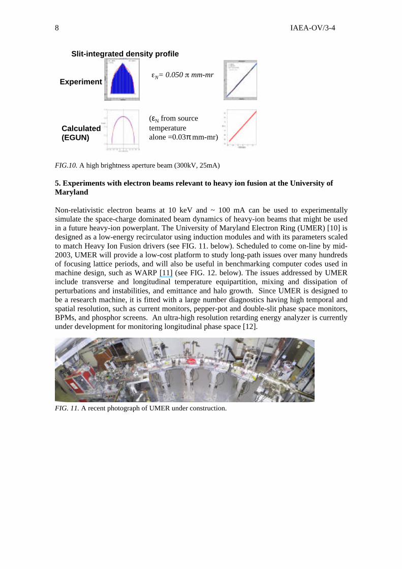
A beam aperturing experiment was performed on NTX to improve the emittance and to varythe beam perveance. A 2-cm diameter aperture was placed downstream of the exit cathode.This aperture intercepted one half (predicted and measured) of the beam current. Secondaryelectrons produced at the aperture were successfully confined by means of two adjacentcylinders with negatively biased potentials. FIG. 9. below shows that electrons neutralizedthe central portion of the ion beam, leading to enhancements of the density on axis andsignificant distortions of the phase space. The measured profiles and phase space werequalitatively consistent with calculations from LSP, a particle-in-cell simulation code, andalso with a version of EGUN adapted to include electron effects. Beam size and thedivergence angle agreed with EGUN predictions. When the electron trap was turned on, auniform profile and phase space were measured, and the emittance was then 0.05 π mm-mr(see FIG. 10 below).
IAEA-OV/3-47
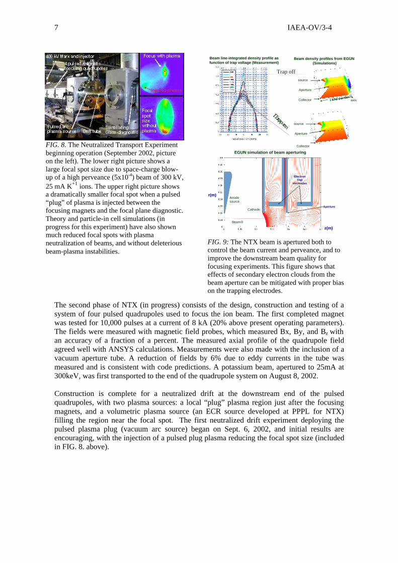
The second phase of NTX (in progress) consists of the design, construction and testing of asystem of four pulsed quadrupoles used to focus the ion beam. The first completed magnetwas tested for 10,000 pulses at a current of 8 kA (20% above present operating parameters).The fields were measured with magnetic field probes, which measured Bx, By, and Bz withan accuracy of a fraction of a percent. The measured axial profile of the quadrupole fieldagreed well with ANSYS calculations. Measurements were also made with the inclusion of avacuum aperture tube. A reduction of fields by 6% due to eddy currents in the tube wasmeasured and is consistent with code predictions. A potassium beam, apertured to 25mA at300keV, was first transported to the end of the quadrupole system on August 8, 2002.
Construction is complete for a neutralized drift at the downstream end of the pulsedquadrupoles, with two plasma sources: a local “plug” plasma region just after the focusingmagnets, and a volumetric plasma source (an ECR source developed at PPPL for NTX)filling the region near the focal spot. The first neutralized drift experiment deploying thepulsed plasma plug (vacuum arc source) began on Sept. 6, 2002, and initial results areencouraging, with the injection of a pulsed plug plasma reducing the focal spot size (includedin FIG. 8. above).
FIG. 9: The NTX beam is apertured both tocontrol the beam current and perveance, and toimprove the downstream beam quality forfocusing experiments. This figure shows thateffects of secondary electron clouds from thebeam aperture can be mitigated with proper biason the trapping electrodes.
FIG. 8. The Neutralized Transport Experimentbeginning operation (September 2002, pictureon the left). The lower right picture shows alarge focal spot size due to space-charge blow-up of a high perveance (5x10⁻⁴) beam of 300 kV,25 mA K+1 ions. The upper right picture showsa dramatically smaller focal spot when a pulsed“plug” of plasma is injected between thefocusing magnets and the focal plane diagnostic.Theory and particle-in cell simulations (inprogress for this experiment) have also shownmuch reduced focal spots with plasmaneutralization of beams, and without deleteriousbeam-plasma instabilities.
Beam line-integrated density profile as function of trap voltage (Measurement)
source
Aperture
Collector
source
Aperture
Collector axis
Beam density profiles from EGUN(Simulations)
Trap off
Trap on
Radial position
EGUN simulation of beam aperturing
z(m)
r(m)
Aperture
Anode source
Cathode
Electron trap
electrodes
Beam�
IAEA-OV/3-48
FIG.10. A high brightness aperture beam (300kV, 25mA)
5. Experiments with electron beams relevant to heavy ion fusion at the University ofMaryland
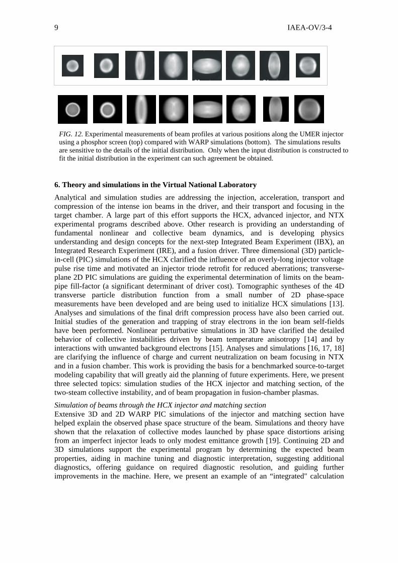
Non-relativistic electron beams at 10 keV and ~ 100 mA can be used to experimentallysimulate the space-charge dominated beam dynamics of heavy-ion beams that might be usedin a future heavy-ion powerplant. The University of Maryland Electron Ring (UMER) [10] isdesigned as a low-energy recirculator using induction modules and with its parameters scaledto match Heavy Ion Fusion drivers (see FIG. 11. below). Scheduled to come on-line by mid-2003, UMER will provide a low-cost platform to study long-path issues over many hundredsof focusing lattice periods, and will also be useful in benchmarking computer codes used inmachine design, such as WARP [11] (see FIG. 12. below). The issues addressed by UMERinclude transverse and longitudinal temperature equipartition, mixing and dissipation ofperturbations and instabilities, and emittance and halo growth. Since UMER is designed tobe a research machine, it is fitted with a large number diagnostics having high temporal andspatial resolution, such as current monitors, pepper-pot and double-slit phase space monitors,BPMs, and phosphor screens. An ultra-high resolution retarding energy analyzer is currentlyunder development for monitoring longitudinal phase space [12].
FIG. 11. A recent photograph of UMER under construction.
Slit-integrated density profile
N= 0.050 mm-mrExperiment
Calculated(EGUN)
(εN from sourcetemperaturealone =0.03π mm-mr)
IAEA-OV/3-49
Q1 Q3 Q4
6. Theory and simulations in the Virtual National Laboratory
Analytical and simulation studies are addressing the injection, acceleration, transport andcompression of the intense ion beams in the driver, and their transport and focusing in thetarget chamber. A large part of this effort supports the HCX, advanced injector, and NTXexperimental programs described above. Other research is providing an understanding offundamental nonlinear and collective beam dynamics, and is developing physicsunderstanding and design concepts for the next-step Integrated Beam Experiment (IBX), anIntegrated Research Experiment (IRE), and a fusion driver. Three dimensional (3D) particle-in-cell (PIC) simulations of the HCX clarified the influence of an overly-long injector voltagepulse rise time and motivated an injector triode retrofit for reduced aberrations; transverse-plane 2D PIC simulations are guiding the experimental determination of limits on the beam-pipe fill-factor (a significant determinant of driver cost). Tomographic syntheses of the 4Dtransverse particle distribution function from a small number of 2D phase-spacemeasurements have been developed and are being used to initialize HCX simulations [13].Analyses and simulations of the final drift compression process have also been carried out.Initial studies of the generation and trapping of stray electrons in the ion beam self-fieldshave been performed. Nonlinear perturbative simulations in 3D have clarified the detailedbehavior of collective instabilities driven by beam temperature anisotropy [14] and byinteractions with unwanted background electrons [15]. Analyses and simulations [16, 17, 18]are clarifying the influence of charge and current neutralization on beam focusing in NTXand in a fusion chamber. This work is providing the basis for a benchmarked source-to-targetmodeling capability that will greatly aid the planning of future experiments. Here, we presentthree selected topics: simulation studies of the HCX injector and matching section, of thetwo-steam collective instability, and of beam propagation in fusion-chamber plasmas.
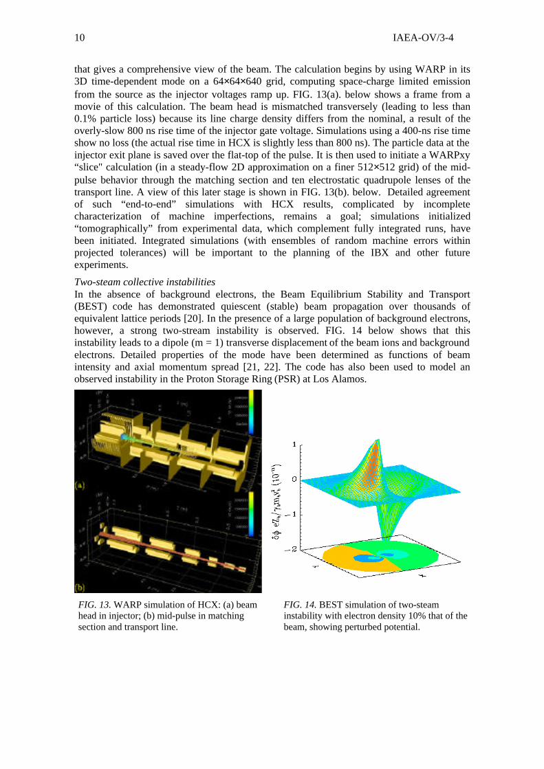
Simulation of beams through the HCX injector and matching sectionExtensive 3D and 2D WARP PIC simulations of the injector and matching section havehelped explain the observed phase space structure of the beam. Simulations and theory haveshown that the relaxation of collective modes launched by phase space distortions arisingfrom an imperfect injector leads to only modest emittance growth [19]. Continuing 2D and3D simulations support the experimental program by determining the expected beamproperties, aiding in machine tuning and diagnostic interpretation, suggesting additionaldiagnostics, offering guidance on required diagnostic resolution, and guiding furtherimprovements in the machine. Here, we present an example of an “integrated" calculation
FIG. 12. Experimental measurements of beam profiles at various positions along the UMER injectorusing a phosphor screen (top) compared with WARP simulations (bottom). The simulations resultsare sensitive to the details of the initial distribution. Only when the input distribution is constructed tofit the initial distribution in the experiment can such agreement be obtained.
IAEA-OV/3-410
that gives a comprehensive view of the beam. The calculation begins by using WARP in its3D time-dependent mode on a 64×64×640 grid, computing space-charge limited emissionfrom the source as the injector voltages ramp up. FIG. 13(a). below shows a frame from amovie of this calculation. The beam head is mismatched transversely (leading to less than0.1% particle loss) because its line charge density differs from the nominal, a result of theoverly-slow 800 ns rise time of the injector gate voltage. Simulations using a 400-ns rise timeshow no loss (the actual rise time in HCX is slightly less than 800 ns). The particle data at theinjector exit plane is saved over the flat-top of the pulse. It is then used to initiate a WARPxy“slice" calculation (in a steady-flow 2D approximation on a finer 512×512 grid) of the mid-pulse behavior through the matching section and ten electrostatic quadrupole lenses of thetransport line. A view of this later stage is shown in FIG. 13(b). below. Detailed agreementof such “end-to-end” simulations with HCX results, complicated by incompletecharacterization of machine imperfections, remains a goal; simulations initialized“tomographically” from experimental data, which complement fully integrated runs, havebeen initiated. Integrated simulations (with ensembles of random machine errors withinprojected tolerances) will be important to the planning of the IBX and other futureexperiments.
Two-steam collective instabilitiesIn the absence of background electrons, the Beam Equilibrium Stability and Transport(BEST) code has demonstrated quiescent (stable) beam propagation over thousands ofequivalent lattice periods [20]. In the presence of a large population of background electrons,however, a strong two-stream instability is observed. FIG. 14 below shows that thisinstability leads to a dipole (m = 1) transverse displacement of the beam ions and backgroundelectrons. Detailed properties of the mode have been determined as functions of beamintensity and axial momentum spread [21, 22]. The code has also been used to model anobserved instability in the Proton Storage Ring (PSR) at Los Alamos.
FIG. 13. WARP simulation of HCX: (a) beamhead in injector; (b) mid-pulse in matchingsection and transport line.
FIG. 14. BEST simulation of two-steaminstability with electron density 10% that of thebeam, showing perturbed potential.
IAEA-OV/3-411
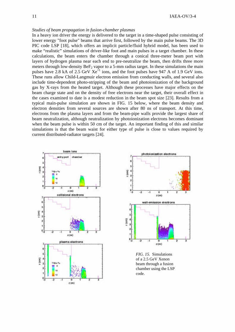
Studies of beam propagation in fusion-chamber plasmasIn a heavy ion driver the energy is delivered to the target in a time-shaped pulse consisting oflower energy "foot pulse" beams that arrive first, followed by the main pulse beams. The 3DPIC code LSP [18], which offers an implicit particle/fluid hybrid model, has been used tomake “realistic” simulations of driver-like foot and main pulses in a target chamber. In thesecalculations, the beam enters the chamber through a conical three-meter beam port withlayers of hydrogen plasma near each end to pre-neutralize the beam, then drifts three moremeters through low-density BeF2 vapor to a 5-mm radius target. In these simulations the mainpulses have 2.8 kA of 2.5 GeV Xe+1 ions, and the foot pulses have 947 A of 1.9 GeV ions.These runs allow Child-Langmuir electron emission from conducting walls, and several alsoinclude time-dependent photo-stripping of the beam and photoionization of the backgroundgas by X-rays from the heated target. Although these processes have major effects on thebeam charge state and on the density of free electrons near the target, their overall effect inthe cases examined to date is a modest reduction in the beam spot size [23]. Results from atypical main-pulse simulation are shown in FIG. 15 below, where the beam density andelectron densities from several sources are shown after 80 ns of transport. At this time,electrons from the plasma layers and from the beam-pipe walls provide the largest share ofbeam neutralization, although neutralization by photoionization electrons becomes dominantwhen the beam pulse is within 50 cm of the target. An important finding of this and similarsimulations is that the beam waist for either type of pulse is close to values required bycurrent distributed-radiator targets [24].
FIG. 15. Simulationsof a 2.5 GeV Xenonbeam through a fusionchamber using the LSPcode.
IAEA-OV/3-412
7. Future plans
After the experiments described in earlier sections are completed, the next step in the HeavyIon Fusion program will be to study transverse and longitudinal emittance growth throughinjection, acceleration, longitudinal beam compression, and final focus in an Integrated BeamExperiment (IBX), a 5-20 MeV, 500 mA beam experiment which is a candidate proof-of-principle experiment for Heavy Ion Fusion in the U.S. Fusion Energy Sciences Program [25].A well-diagnosed IBX, together with well-benchmarked integrated models, should improvefocal spot predictive capability for future high-energy-density ion-target interactionexperiments.
Heavy Ion Fusion has significant potential for lower cost experiments through innovativetechnology: higher current density merging-beamlet injectors; high-field, compactsuperconducting quadrupoles, agile-waveform induction modules; and high-gradientinsulators. Experiments on neutralizing beam space charge in the chamber may lead to lowervoltage and lower cost drivers. Innovative target designs may increase allowed beam spotsize, and fast ignition may reduce peak ion beam power, lengthen pulse durations, and allowlarger focal spot size.
Appendix 1: References
[1] BANGERTER, R.O., et al., “The heavy ion fusion program in the USA”, presented at the18th International Conference on Plasma Physics and Controlled Fusion, IAEA-CN-77/OV3/3, Sorrento, Italy. LBNL-46933.[2] TABAK, M., et al., “Target design activities for inertial fusion energy at LawrenceLivermore National Laboratory”, Proc. of the 18th International Conference on PlasmaPhysics and Controlled Fusion, IAEA-CN-77/IF-2, Sorrento, Italy.[3] MEIER, W.R., et al., “Addressing key science and technology issues for IFE chambers,target fabrication and target injection”, IAEA-CN-94/FT/1-3Ra, 2002, these proceedings.[4] SEIDL, P.A., et al., “Overview of the scientific objectives of the high current experimentfor heavy-ion fusion”, Proc. 2001 Part. Accel. Conf. pp. 2932-2934, IEEE #01CH37268C.LBNL-49319.[5] MOLVIK, A.W., et al., “Electron effects in intense, ion beam linacs theory andexperimental planning for HCX”, to be published in Laser and Particle Beam 20 (4), 2002.LBNL-51009.[6] FALTENS, A., et al., “Development of superconducting magnets for heavy ion fusion”,to be published in Laser and Particle Beams 20 (4), 2002. LBNL-50869.[7] BURKHART, C., “The closed-loop amplifier regulated driver, a high accuracy, low costmodulator for HIF accelerators”, US Dept. of Energy SBIR final Report, DE-FG03-00ER83010, May 2001.[8] GROTE, D.P., et al., “Design and simulation of the multi-beamlet injector for a highcurrent accelerator”, submitted for publication to Physical Review Special Topics onAccelerators and Beams.[9] AHLE, L., et al., “Rf gas plasma source development for heavy ion fusion”, Rev. Sci.Instrum, Vol. 73, p. 1039, (2002).[10] O’SHEA, P.G., et al., “Experiments with space charge dominated beams for heavy ionfusion applications”, submitted for publication to Laser and Particle Beams, 20 (4), 2002.
IAEA-OV/3-413
[11] GROTE, D.P., et al., “Three-dimensional simulations of high current beams in inductionaccelerators with WARP3d”, published in Fusion Engineering and Design, 32-32 (1996)193-200.[12] ZOU, Y., et al., “Compact high-resolution retarding field energy analyzer for space-charge-dominated electron beams”, PRST-AB 5, 072801 (2002).[13] FRIEDMAN, A., et al., “Use of projectional phase space data to infer a 4d particledistribution”, to be published in Laser and Particle Beams, Beam 20 (4), 2002. LBNL-51211,UCRL-JC-148436.[14] STARTSEV, E.A., et al., “Nonlinear δf simulation studies of intense charged particlebeams with large temperature anisotropy”, to be published in Laser and Particle Beams,Beam 20 (4), 2002. HIFAC 1027.[15] QIN, H., et al., “Nonlinear δf simulation studies of the electron ion two-streaminstabilities in high intensity beams”, to be published in Laser and Particle Beams, Beam 20(4), 2002. HIFAC 1025.[16] KAGANOVICH, I., et al. (2001), Phys. Plasmas 8, 4180.[17] HUGHES, T. P., et al., (1999), Phys. Rev. ST-AB 2, 110401.[18] WELCH, D.R., et al, “Simulations of intense heavy ion beams propagating through agaseous fusion target chamber”, (2002), Phys. Plasmas 9, 2344.[19] CELATA, C.M., et al., “Particle-in-cell simulation on heavy ion inertial fusion”,submitted for publication to Laser and Particle Beams 20 (4), 2002.[20] DAVIDSON, R. C., et al., (2001), “Physics of intense charged particle beams in highenergy accelerators” (World Scientific, Singapore).[21] QIN, H., et al., (2001), Proceedings of the 2001 Particle Accelerator Conference, pp.696-701.[22] QIN, H., et al., (2000), Physical Review Special Topics on Accelerators and Beams 3,084401; 109901.[23] SHARP, W.M., et al., “Effects of photoionization on heavy-ion-fusion chambertransport”, to be published in Laser and Particle Beam 20 (4), 2002.[24] CALLAHAN-MILLER, D.A., et al., “Target design activities for inertial fusion energyat Lawrence Livermore National Laboratory”, Nucl. Fusion 39, 1999, 883.[25] BARNARD, J.J., et al., “Integrated experiments for heavy ion fusion”, to be published inLaser and Particle Beam 20 (4), 2002.
Appendix 2: Keyword Index
heavy ion driven inertial fusion
∗ This work was performed under auspices of the U.S. Department of Energy by the University of California,Lawrence Berkeley and Lawrence Livermore National Laboratories under Contract Numbers DE-AC03-76SF00098 and W-7405-Eng-48, Princeton Plasma Physics Laboratory under Contract Number DE-AC02-76CH03073, and by the University of Maryland under contract numbers DE-FG02-94ER40855 and DE-FG02-92ER54178.
Related Documents