SOFTWARE PROGRAM MANUAL MUAP-07017(R0) Mitsubishi Heavy Industries, Ltd. US-APWR Technical Report Software Program Manual December 2007 ©2007 Mitsubishi Heavy Industries, Ltd. All Rights Reserved

Welcome message from author
This document is posted to help you gain knowledge. Please leave a comment to let me know what you think about it! Share it to your friends and learn new things together.
Transcript
SOFTWARE PROGRAM MANUAL MUAP-07017(R0)
Mitsubishi Heavy Industries, Ltd.
US-APWR Technical Report
Software Program Manual
December 2007
©2007 Mitsubishi Heavy Industries, Ltd. All Rights Reserved

SOFTWARE PROGRAM MANUAL MUAP-07017(R0)
Mitsubishi Heavy Industries, Ltd. i
Revision History
Revision Page Description
0 All Original issued

SOFTWARE PROGRAM MANUAL MUAP-07017(R0)
Mitsubishi Heavy Industries, Ltd. ii
© 2007 MITSUBISHI HEAVY INDUSTRIES, LTD.
All Rights Reserved
This document has been prepared by Mitsubishi Heavy Industries, Ltd. (“MHI”) in connection with the U.S. Nuclear Regulatory Commission (“NRC”) licensing review of MHI’s US-APWR nuclear power plant design. None of the information in this document, may be disclosed, used or copied without written permission of MHI, other than by the NRC and its contractors in support of the licensing review of the US-APWR. This document contains technological information and intellectual property relating to the US-APWR and it is delivered to the NRC on the express condition that it not be disclosed, copied or reproduced in whole or in part, or used for the benefit of anyone other than MHI without the express written permission of MHI, except as set forth in the previous paragraph. This document is protected by the laws of Japan, U.S. copyright law, international treaties and conventions, and the applicable laws of any country where it is being used.
Mitsubishi Heavy Industries, Ltd. 16-5, Konan 2-chome, Minato-ku
Tokyo 108-8215 Japan
SOFTWARE PROGRAM MANUAL MUAP-07017(R0)
Mitsubishi Heavy Industries, Ltd. iii
Abstract
This Software Program Manual (SPM) describes the processes, which ensure the reliability and design quality of the US-APWR Protection and Safety Monitoring System (PSMS) application software throughout its entire lifecycle. By following this SPM, the digital safety I&C system software achieves high functionality and high quality as shown below.
• Application software for the PSMS achieves a quality level expected for nuclear
plant safety functions.
• Application software provides the required safety functions.
• The processes and procedures described in this SPM are based on established technical and document control requirements, practices, rules and industrial standards.
SOFTWARE PROGRAM MANUAL MUAP-07017(R0)
Mitsubishi Heavy Industries, Ltd. iv
Table of Contents
List of Tables List of Figures List of Acronyms 1.0 INTRODUCTION ............................................................................................................... 1
1.1 Purpose.......................................................................................................................... 1 1.2 Scope............................................................................................................................. 1
2.0 SOFTWARE LIFECYCLE PROCESS CONTROL............................................................. 2
2.1 Purpose.......................................................................................................................... 2 2.2 Organization and Responsibilities.................................................................................. 4
2.2.1 Organization ............................................................................................................ 4 2.2.2 Responsibilities ....................................................................................................... 4
2.3 General Requirements ................................................................................................... 5 2.3.1 Overview of Lifecycle............................................................................................... 5 2.3.2 Classification of Software ........................................................................................ 6 2.3.3 Documentation ........................................................................................................ 6
3.0 SOFTWARE LIFECYCLE PLANS ..................................................................................... 8
3.1 Software Management Plan........................................................................................... 9 3.1.1 Purpose ................................................................................................................... 9 3.1.2 Organization/Responsibilities ................................................................................ 13 3.1.3 Oversight ............................................................................................................... 13 3.1.4 Security ................................................................................................................. 14 3.1.5 Measurement ........................................................................................................ 14 3.1.6 Procedures ............................................................................................................ 14 3.1.7 Budget ................................................................................................................... 15 3.1.8 Methods................................................................................................................. 15 3.1.9 Personnel .............................................................................................................. 15
3.2 Software Development Plan......................................................................................... 16 3.2.1 Purpose ................................................................................................................. 16 3.2.2 Organization .......................................................................................................... 16 3.2.3 Oversight ............................................................................................................... 16 3.2.4 Risks...................................................................................................................... 16 3.2.5 Measurement ........................................................................................................ 17 3.2.6 Procedures ............................................................................................................ 17 3.2.7 Schedule ............................................................................................................... 17 3.2.8 Methods/tools ........................................................................................................ 17 3.2.9 Standards .............................................................................................................. 17
3.3 Software Quality Assurance Plan................................................................................. 18 3.3.1 Purpose ................................................................................................................. 18 3.3.2 Organization/Responsibilities ................................................................................ 18 3.3.3 Security ................................................................................................................. 18 3.3.4 Measurement ........................................................................................................ 18 3.3.5 Procedures ............................................................................................................ 18 3.3.6 Record Keeping..................................................................................................... 21 3.3.7 Methods/Tools ....................................................................................................... 21 3.3.8 Standards .............................................................................................................. 22
SOFTWARE PROGRAM MANUAL MUAP-07017(R0)
Mitsubishi Heavy Industries, Ltd. v
3.4 Software Integration Plan............................................................................................. 23
3.4.1 Purpose ................................................................................................................. 23 3.4.2 Organization/Responsibilities ................................................................................ 23 3.4.3 Measurement ........................................................................................................ 23 3.4.4 Procedures ............................................................................................................ 23 3.4.5 Methods/tools ........................................................................................................ 24
3.5 Software Installation Plan............................................................................................. 25 3.5.1 Purpose ................................................................................................................. 25 3.5.2 Organization/Responsibilities ................................................................................ 25 3.5.3 Measurement ........................................................................................................ 25 3.5.4 Procedures ............................................................................................................ 26 3.5.5 Methods/tools ........................................................................................................ 26
3.6 Software Maintenance Plan ......................................................................................... 27 3.6.1 Purpose ................................................................................................................. 27 3.6.2 Organization/Responsibilities ................................................................................ 27 3.6.3 Risks...................................................................................................................... 27 3.6.4 Security ................................................................................................................. 27 3.6.5 Measurement ........................................................................................................ 27 3.6.6 Procedures ............................................................................................................ 27 3.6.7 Resources ............................................................................................................. 28
3.7 Software Training Plan ................................................................................................. 29 3.7.1 Purpose ................................................................................................................. 29 3.7.2 Organization/Responsibilities ................................................................................ 29 3.7.3 Measurement ........................................................................................................ 29 3.7.4 Procedure.............................................................................................................. 29 3.7.5 Resources ............................................................................................................. 30
3.8 Software Operation Plan .............................................................................................. 31 3.8.1 Purpose ................................................................................................................. 31 3.8.2 Organization/Responsibility ................................................................................... 31 3.8.3 Security ................................................................................................................. 31 3.8.4 Measurement ........................................................................................................ 32 3.8.5 Procedures ............................................................................................................ 32 3.8.6 Methods/tools ........................................................................................................ 32
3.9 Software Safety Plan.................................................................................................... 33 3.9.1 Purpose ................................................................................................................. 33 3.9.2 Organization/Responsibilities ................................................................................ 33 3.9.3 Risks...................................................................................................................... 33 3.9.4 Measurement ........................................................................................................ 33 3.9.5 Procedures ............................................................................................................ 34 3.9.6 Methods/tools ........................................................................................................ 34 3.9.7 Standards .............................................................................................................. 34
3.10 Software Verification and Validation Plan................................................................... 35 3.10.1 Purpose ............................................................................................................... 35 3.10.2 Organization/Responsibilities .............................................................................. 35 3.10.3 Oversight ............................................................................................................. 35 3.10.4 Risks.................................................................................................................... 35 3.10.5 Measurement ...................................................................................................... 36 3.10.6 Procedures .......................................................................................................... 36 3.10.7 Methods/tools ...................................................................................................... 40 3.10.8 Standards ............................................................................................................ 40
SOFTWARE PROGRAM MANUAL MUAP-07017(R0)
Mitsubishi Heavy Industries, Ltd. vi
3.11 Software Configuration Management Plan................................................................. 41
3.11.1 Purpose ............................................................................................................... 41 3.11.2 Scope................................................................................................................... 41 3.11.3 Organization/Responsibilities .............................................................................. 42 3.11.4 Security................................................................................................................ 44 3.11.5 Measurement....................................................................................................... 44 3.11.6 Procedures .......................................................................................................... 44 3.11.7 Record Keeping ................................................................................................... 46 3.11.8 Methods/tools ...................................................................................................... 47 3.11.9 Standards............................................................................................................. 47
3.12 Software Test Plan ..................................................................................................... 48 3.12.1 Purpose ............................................................................................................... 48 3.12.2 Organization/Responsibilities .............................................................................. 48 3.12.3 Security ............................................................................................................... 48 3.12.4 Measurement ...................................................................................................... 48 3.12.5 Procedures .......................................................................................................... 48 3.12.6 Record Keeping................................................................................................... 50 3.12.7 Methods/tools ...................................................................................................... 50 3.12.8 Standards ............................................................................................................ 51
4.0 OUTPUT DOCUMENTS.................................................................................................. 52 5.0 REFERENCES ................................................................................................................ 54
SOFTWARE PROGRAM MANUAL MUAP-07017(R0)
Mitsubishi Heavy Industries, Ltd. vii
List of Tables
Table 2.1-1 Correspondence to BTP 7-14 -------------------------------------------------------------3 Table 3.1-1 Overview of Software Lifecycle Process --------------------------------------------- 10 Table 4.0-1 Output Documents in Software Lifecycle Process --------------------------------- 52
List of Figures
Figure 2.2-1 Organizational Structure to Control the Software Lifecycle Process ----------4 Figure 3.0-1 Overview of Software Lifecycle Plan---------------------------------------------------8
SOFTWARE PROGRAM MANUAL MUAP-07017(R0)
Mitsubishi Heavy Industries, Ltd. viii
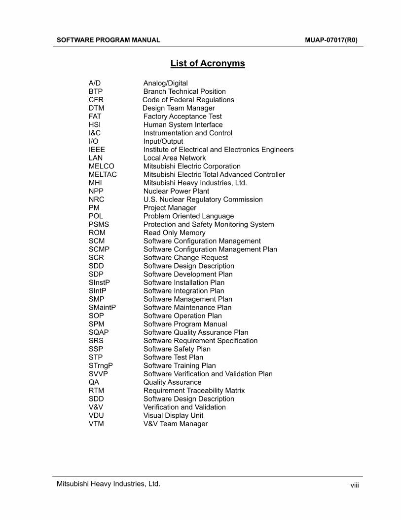
List of Acronyms
A/D Analog/Digital BTP Branch Technical Position CFR Code of Federal Regulations DTM Design Team Manager FAT Factory Acceptance Test HSI Human System Interface I&C Instrumentation and Control I/O Input/Output IEEE Institute of Electrical and Electronics Engineers LAN Local Area Network MELCO Mitsubishi Electric Corporation MELTAC Mitsubishi Electric Total Advanced Controller MHI Mitsubishi Heavy Industries, Ltd. NPP Nuclear Power Plant NRC U.S. Nuclear Regulatory Commission PM Project Manager POL Problem Oriented Language PSMS Protection and Safety Monitoring System ROM Read Only Memory SCM Software Configuration Management SCMP Software Configuration Management Plan SCR Software Change Request SDD Software Design Description SDP Software Development Plan SInstP Software Installation Plan SIntP Software Integration Plan SMP Software Management Plan SMaintP Software Maintenance Plan SOP Software Operation Plan SPM Software Program Manual SQAP Software Quality Assurance Plan SRS Software Requirement Specification SSP Software Safety Plan STP Software Test Plan STrngP Software Training Plan SVVP Software Verification and Validation Plan QA Quality Assurance RTM Requirement Traceability Matrix SDD Software Design Description V&V Verification and Validation VDU Visual Display Unit VTM V&V Team Manager
SOFTWARE PROGRAM MANUAL MUAP-07017(R0)
Mitsubishi Heavy Industries, Ltd. 1
1.0 INTRODUCTION 1.1 Purpose In this Software Program Manual (SPM), Mitsubishi Heavy Industries, Ltd. (hereinafter shown as “MHI”) defines the quality assurance requirements which govern the application software lifecycle for the digital safety Instrumentation and Control (I&C) system of the US-APWR. The digital safety I&C system is defined as the Protection and Safety Monitoring System (PSMS) in the US-APWR. This SPM provides the software program plans based in the guidance of Branch Technical Position (BTP) 7-14, “Guidance on Software Reviews for Digital Computer-Based I&C Systems” (Reference 1). 1.2 Scope This SPM shall be applied to the design, production and maintenance of application software for the US-APWR PSMS. The software lifecycle shall be implemented, operated and maintained based on the program plans of this SPM. During the operation of the PSMS, the responsibility of the application software life cycle may become the responsibility of the nuclear plant maintenance or engineering organization. Should this occur, the nuclear plant organization shall maintain the application software in accordance with the plans of this SPM, and in accordance with their Quality Assurance (QA) manual. The plans provided in this SPM are applicable to all the US-APWR projects. These plans describe requirements for specific documentation, which is generated during execution of a specific project. Some plans require additional planning detail, which is also developed during the execution of a specific project. This additional planning detail shall be provided within an overall Project Plan; specific project plans are not required for each element of this SPM. The Project Plan shall also reference specific procedures used to implement the requirements of this SPM. These procedures are specific to the organization responsible for a particular area of the software lifecycle. Organizational division of responsibility is described in Section 2.2.
SOFTWARE PROGRAM MANUAL MUAP-07017(R0)
Mitsubishi Heavy Industries, Ltd. 2
2.0 SOFTWARE LIFECYCLE PROCESS CONTROL 2.1 Purpose The MELTAC platform is applied for the digital I&C systems of the US-APWR. The MELTAC platform includes hardware and basic software for the digital I&C system. The MELTAC platform, including the lifecycle process for the MELTAC basic software, is described in MUAP-07005 (Reference 2). This SPM describes the overall management of the application software lifecycle including design, manufacturing, integration, tests, installation, operation, maintenance, training, safety plan, Verification and Validation (V&V) and configuration management.
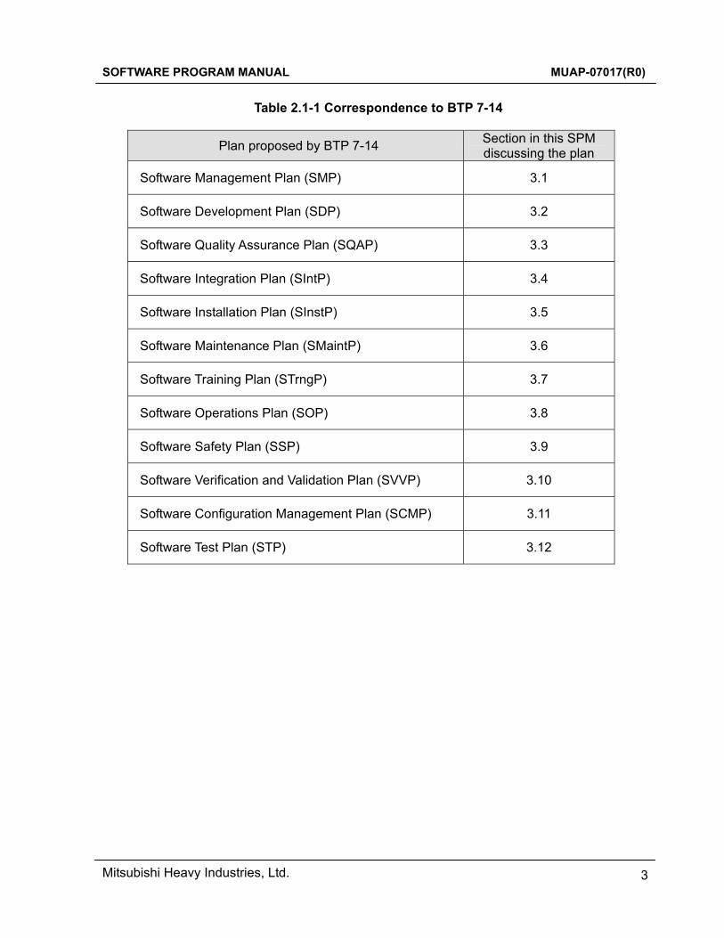
Table 2.1-1 shows the software lifecycle plans described in this SPM and their correlation to the plans described in BTP 7-14. As defined in various plans described in Section 3.0, instructions and procedures shall be prepared in accordance with the requirements specified in this SPM.
SOFTWARE PROGRAM MANUAL MUAP-07017(R0)
Mitsubishi Heavy Industries, Ltd. 3
Table 2.1-1 Correspondence to BTP 7-14
Plan proposed by BTP 7-14 Section in this SPM discussing the plan
Software Management Plan (SMP) 3.1
Software Development Plan (SDP) 3.2
Software Quality Assurance Plan (SQAP) 3.3
Software Integration Plan (SIntP) 3.4
Software Installation Plan (SInstP) 3.5
Software Maintenance Plan (SMaintP) 3.6
Software Training Plan (STrngP) 3.7
Software Operations Plan (SOP) 3.8
Software Safety Plan (SSP) 3.9
Software Verification and Validation Plan (SVVP) 3.10
Software Configuration Management Plan (SCMP) 3.11
Software Test Plan (STP) 3.12
SOFTWARE PROGRAM MANUAL MUAP-07017(R0)
Mitsubishi Heavy Industries, Ltd. 4
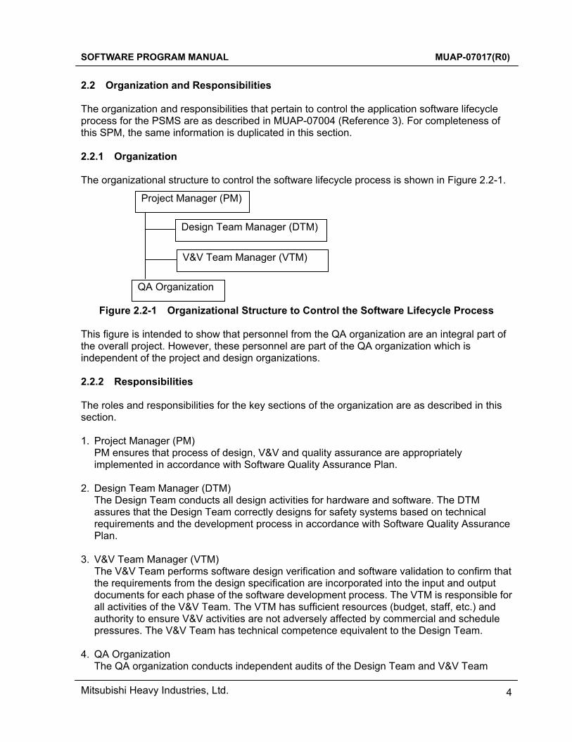
2.2 Organization and Responsibilities The organization and responsibilities that pertain to control the application software lifecycle process for the PSMS are as described in MUAP-07004 (Reference 3). For completeness of this SPM, the same information is duplicated in this section. 2.2.1 Organization The organizational structure to control the software lifecycle process is shown in Figure 2.2-1.
Figure 2.2-1 Organizational Structure to Control the Software Lifecycle Process This figure is intended to show that personnel from the QA organization are an integral part of the overall project. However, these personnel are part of the QA organization which is independent of the project and design organizations. 2.2.2 Responsibilities The roles and responsibilities for the key sections of the organization are as described in this section. 1. Project Manager (PM)
PM ensures that process of design, V&V and quality assurance are appropriately implemented in accordance with Software Quality Assurance Plan.
2. Design Team Manager (DTM)
The Design Team conducts all design activities for hardware and software. The DTM assures that the Design Team correctly designs for safety systems based on technical requirements and the development process in accordance with Software Quality Assurance Plan.
3. V&V Team Manager (VTM)
The V&V Team performs software design verification and software validation to confirm that the requirements from the design specification are incorporated into the input and output documents for each phase of the software development process. The VTM is responsible for all activities of the V&V Team. The VTM has sufficient resources (budget, staff, etc.) and authority to ensure V&V activities are not adversely affected by commercial and schedule pressures. The V&V Team has technical competence equivalent to the Design Team.
4. QA Organization
The QA organization conducts independent audits of the Design Team and V&V Team
Project Manager (PM)
Design Team Manager (DTM)
V&V Team Manager (VTM)
QA Organization
SOFTWARE PROGRAM MANUAL MUAP-07017(R0)
Mitsubishi Heavy Industries, Ltd. 5
activities to confirm that requirements and implementation of the application software lifecycle process are appropriately planned and executed in accordance with the Software Quality Assurance Plan.
The QA organization assures that any design or V&V activities subcontracted to other organizations also comply in accordance with the Software Quality Assurance Plan, This includes conformance of the suppliers’ overall QA program.
2.3 General Requirements 2.3.1 Overview of Lifecycle Overview of lifecycle processes and activities are described in MUAP-07004. For completeness of this SPM, the same information is duplicated in this section.
1. Plant requirements phase This phase defines the requirements and the key design aspects for all I&C systems that are critical to the plant’s design basis for safety, performance and maintainability. This phase determines the industry regulations and standards that apply to the I&C systems and the design process for those systems. Key documents produced during this phase include Plant Licensing Documentation and quality program documents, such as the Software Life Cycle Process documents described in Section 6.3.1 of MUAP-07004.
2. System requirements phase
During this phase the system requirement specifications are written for each I&C system. These specifications define performance, functional and Human System Interface (HSI) requirements, and system interfaces. The specifications also define the digital platform and basic architecture of each system using that platform.
3. Hardware/software requirements phase
This phase produces specifications for hardware and software. Hardware specifications define the configuration of basic platform modules into chassis and cabinets. Electrical power, interface designs and application software specifications are documented in block diagrams and sequence diagrams. The software specification defines the functions and architecture of the software, including key partitions and interfaces. The functional design is documented primarily in logic diagrams and graphical screen layouts. The hardware and software specifications also define key requirements for Unit Testing and Integration Testing.
During this phase the analysis described in Section 6.5 of MUAP-07004 are also conducted to confirm as much of the design as possible. Some aspects of the analysis may be based on assumptions that are confirmed, or revised as necessary, in later phases of the design process.
4. Hardware/software design and production phase
During this phase the basic platform hardware is manufactured and configured in cabinets with all power and signal wiring. Application software is also created for all controllers and HSI devices. Unit testing is conducted as required by the software specification. During this phase operations and maintenance manuals are created.

SOFTWARE PROGRAM MANUAL MUAP-07017(R0)
Mitsubishi Heavy Industries, Ltd. 6
5. Factory test phase During this phase basic software and application software are integrated with the platform hardware for each system. A series of integration tests validates the designs first at the system level and then at the level of all I&C systems integration. Operations and maintenance manuals are also validated during this phase.
6. Installation and commissioning phase
Activities in this phase are installation check and commissioning. During this phase controllers are connected with field equipments such as detectors, actuators. Pre-operational tests are conducted to ensure all equipment has not been damaged during shipping or installation and that all interconnections are correct. Additional functional testing may be conducted as required by plant design requirements.
7. Operation phase
During this phase the I&C systems are in operation. Self-diagnostics continuously monitor performance and calibration and manual tests are conducted periodically. Failed equipment is replaced. Software or hardware may be upgraded occasionally to accommodate new requirements, correct design errors or manage obsolescence.
2.3.2 Classification of Software Application software for the US-APWR reflects the basic requirements presented in the system requirement specification and Software Requirement Specifications (SRS), etc. This software is compiled in executable files, and loaded in the processing modules of the MELTAC controllers together with the MELTAC basic software. These modules execute each function to establish communication channels in other modules, and actuate the I/O module. Since this software is duplicated in all redundant safety trains and channels, if a nonconformance occurs in this software, the plant safety function may be violated. Therefore, the application software is essential for execution of the safety functions. As a result, this system is classified as Class 1E based on the definition of IEEE Std 603-1991 (Reference 4), and the application software is classified as software integrity level (level 4) based on the definition of IEEE Std 7-4.3.2-2003 (Reference 5). 2.3.3 Documentation Each software lifecycle plan requires output documentation. The output documents are defined in the Section 4.0. These documents shall meet the following requirements: The documentation provides evidences for the integrity of the development process so that the reliability of the safety software may be ensured. The documentation provides “Transparency” and “Traceability”. The documents related to design and installation of the safety software must be clear and correct. Documentation allows traceability of the decisions made during the design process documents for each step of the development process shall be prepared. The documents prepared must be updated through the whole process of repetitive development including trial operation and ongoing operations and maintenance. The designer must be aware of all documentation requirements at the initial stage of the project. The requirements, design and software must be documented correctly so that the designer, programmer and V&V Team reviewer may completely understand all the stages of
SOFTWARE PROGRAM MANUAL MUAP-07017(R0)
Mitsubishi Heavy Industries, Ltd. 7
development and verify the completeness and correctness of each stage. Precise documentation is essential for maintenance. Appropriate documentation prevents errors when anything is changed in a way that affects maintenance in the future. Documents must be easy to understand, and amend. Documents must provide correctness, traceability and completeness, consistency, verifiability and correctability. Additional regulatory review may also be required, depending on the phase of the nuclear plant licensing process. The revised plan shall be distributed to all PSMS PMs.
SOFTWARE PROGRAM MANUAL MUAP-07017(R0)
Mitsubishi Heavy Industries, Ltd. 8
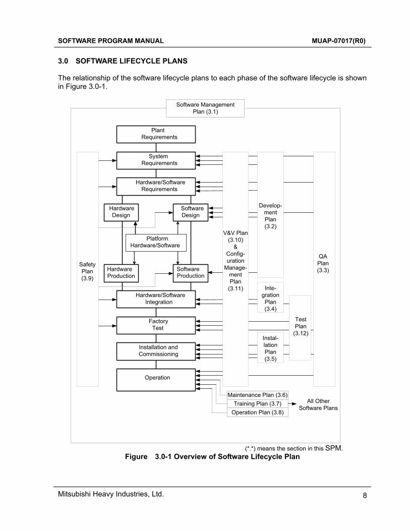
3.0 SOFTWARE LIFECYCLE PLANS The relationship of the software lifecycle plans to each phase of the software lifecycle is shown in Figure 3.0-1.
QAPlan(3.3)
PlatformHardware/Software
SystemRequirements
PlantRequirements
Hardware/SoftwareRequirements
HardwareDesign
SoftwareProduction
HardwareProduction
SoftwareDesign
Hardware/SoftwareIntegration
FactoryTest
Installation and Commissioning
Operation
Instal-lation Plan(3.5)
Test Plan
(3.12)
Inte-gration Plan(3.4)
Develop-ment Plan(3.2)
SafetyPlan(3.9)
Maintenance Plan (3.6)Training Plan (3.7)
Operation Plan (3.8)
Software Management Plan (3.1)
All Other Software Plans
V&V Plan(3.10)
&Config-uration
Manage-mentPlan
(3.11)
(*.*) means the section in this SPM.
Figure 3.0-1 Overview of Software Lifecycle Plan
SOFTWARE PROGRAM MANUAL MUAP-07017(R0)
Mitsubishi Heavy Industries, Ltd. 9
3.1 Software Management Plan 3.1.1 Purpose This section describes the basic strategy and process for managing the software lifecycle. It also describes the method for monitoring progress against the Project Plan, and the method for identifying any deviations from the Project Plan. The application software governed by this SPM implements all functions of the PSMS. The key functions of the PSMS are summarized as follows:
• Input process signals and manual system level actuation signals to the Reactor Protection System and the Engineered Safety Feature Actuation System
• Signal processing such as A/D conversion, comparison between input signal and setpoints, trip/actuation algorithm calculation and 2-out-of-4 logic
• Output reactor trip signal and actuation signal of Engineered Safety Features • Input process signals for accident monitoring and safe shutdown instrumentation • Manual component level controls for credited operator actions for accident
mitigation and for achieving and maintaining safe shutdown • Self-diagnosis • Operating bypasses, maintenance bypasses and periodic surveillance testing • Safety related HSI for the Main Control Room and Remote Shutdown Room to
monitor, control and test all safety functions To implement the above functions with the necessary performance and reliability, the PSMS has the following configuration:
• A digital system with functions that are distributed to multiple computers • The computer platform (i.e. hardware and basic software) is qualified and approved
by U.S. Nuclear Regulatory Commission (NRC) for safety related applications • Four redundant and independent measurement channels with 2-out-of-4
trip/actuation logic • Four redundant and independent trip/actuation trains • Flat panel Visual Display Units (VDUs) provide the HSI for monitoring of all safety
related plant instrumentation and control of all safety related plant components. Communication isolation between redundant PSMS trains and between the PSMS and non-safety systems, which utilizes separate communication processors and optical signal transmission
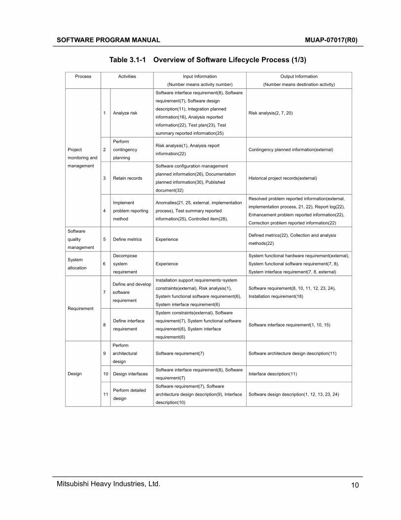
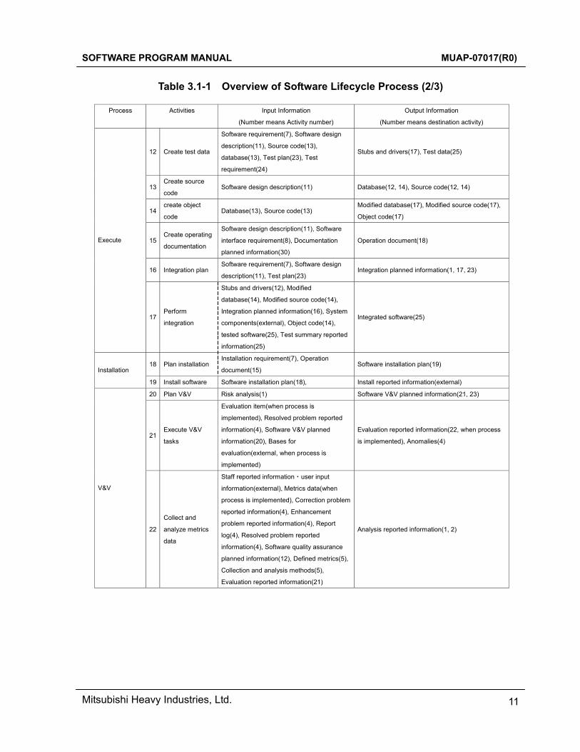
The activities described in Table 3.1-1 are executed in accordance with this SPM.
SOFTWARE PROGRAM MANUAL MUAP-07017(R0)
Mitsubishi Heavy Industries, Ltd. 10
Table 3.1-1 Overview of Software Lifecycle Process (1/3)
Process Activities Input Information
(Number means activity number)
Output Information
(Number means destination activity)
1 Analyze risk
Software interface requirement(8), Software
requirement(7), Software design
description(11), Integration planned
information(16), Analysis reported
information(22), Test plan(23), Test
summary reported information(25)
Risk analysis(2, 7, 20)
2
Perform
contingency
planning
Risk analysis(1), Analysis report
information(22) Contingency planned information(external)
3 Retain records
Software configuration management
planned information(26), Documentation
planned information(30), Published
document(32)
Historical project records(external)
Project
monitoring and
management
4
Implement
problem reporting
method
Anomalies(21, 25, external, implementation
process), Test summary reported
information(25), Controlled item(28),
Resolved problem reported information(external,
implementation process, 21, 22), Report log(22),
Enhancement problem reported information(22),
Correction problem reported information(22)
Software
quality
management
5 Define metrics Experience Defined metrics(22), Collection and analysis
methods(22)
System
allocation 6
Decompose
system
requirement
Experience
System functional hardware requirement(external),
System functional software requirement(7, 8),
System interface requirement(7, 8, external)
7
Define and develop
software
requirement
Installation support requirements・system
constraints(external), Risk analysis(1),
System functional software requirement(6),
System interface requirement(6)
Software requirement(8, 10, 11, 12, 23, 24),
Installation requirement(18)
Requirement
8 Define interface
requirement
System constraints(external), Software
requirement(7), System functional software
requirement(6), System interface
requirement(6)
Software interface requirement(1, 10, 15)
9
Perform
architectural
design
Software requirement(7) Software architecture design description(11)
10 Design interfaces Software interface requirement(8), Software
requirement(7) Interface description(11) Design
11 Perform detailed
design
Software requirement(7), Software
architecture design description(9), Interface
description(10)
Software design description(1, 12, 13, 23, 24)
SOFTWARE PROGRAM MANUAL MUAP-07017(R0)
Mitsubishi Heavy Industries, Ltd. 11
Table 3.1-1 Overview of Software Lifecycle Process (2/3)
Process Activities
Input Information
(Number means Activity number)
Output Information
(Number means destination activity)
12 Create test data
Software requirement(7), Software design
description(11), Source code(13),
database(13), Test plan(23), Test
requirement(24)
Stubs and drivers(17), Test data(25)
13 Create source
code Software design description(11) Database(12, 14), Source code(12, 14)
14 create object
code Database(13), Source code(13)
Modified database(17), Modified source code(17),
Object code(17)
15 Create operating
documentation
Software design description(11), Software
interface requirement(8), Documentation
planned information(30)
Operation document(18)
16 Integration plan Software requirement(7), Software design
description(11), Test plan(23) Integration planned information(1, 17, 23)
Execute
17 Perform
integration
Stubs and drivers(12), Modified
database(14), Modified source code(14),
Integration planned information(16), System
components(external), Object code(14),
tested software(25), Test summary reported
information(25)
Integrated software(25)
18 Plan installation Installation requirement(7), Operation
document(15) Software installation plan(19)
Installation
19 Install software Software installation plan(18), Install reported information(external)
20 Plan V&V Risk analysis(1) Software V&V planned information(21, 23)
21 Execute V&V
tasks
Evaluation item(when process is
implemented), Resolved problem reported
information(4), Software V&V planned
information(20), Bases for
evaluation(external, when process is
implemented)
Evaluation reported information(22, when process
is implemented), Anomalies(4)
V&V
22
Collect and
analyze metrics
data
Staff reported information・user input
information(external), Metrics data(when
process is implemented), Correction problem
reported information(4), Enhancement
problem reported information(4), Report
log(4), Resolved problem reported
information(4), Software quality assurance
planned information(12), Defined metrics(5),
Collection and analysis methods(5),
Evaluation reported information(21)
Analysis reported information(1, 2)

SOFTWARE PROGRAM MANUAL MUAP-07017(R0)
Mitsubishi Heavy Industries, Ltd. 12
Table 3.1-1 Overview of Software Lifecycle Process (3/3)
Process Activities
Input Information
(Number means Activity number)
Output Information
(Number means destination activity)
23 Plan testing
Software requirement(7), Software
requirement(7), Software design
description(11), Integration planned
information(16), Software V&V planned
information(20)
Test plan(1, 12, 16, 24, 25)
24 Develop test
requirement
Software requirement(7), Software design
description(11), Test plan(23) Test requirement(12, 25)
V&V
(continue)
25 Execute the tests
Test environment components (external),
test data(12), Integrated software(17), test
plan(23), Test requirement(24)
Test summary reported information(1, 4, 17,
external), Tested software(17), Anomalies(4)
26 Plan configuration
management
Product list(external), Configuration
identification(27)
Software configuration management planned
information(3, 27, 28, 29)
27
Develop
configuration
identification
Software configuration management planned
information(26) Configuration identification(26)
28
Perform
configuration
control
Controlled item(when process is
implemented), Software configuration
management planned information(26)
Change status(29), Controlled item(4, when
process is implemented)
Configuration
management
29 Perform status
accounting
Software configuration management planned
information(26), Change status(28) Status reported information(external)
30 Plan
documentation contractual requirement(external) Documentation planned information(3, 15, 31, 32)
31 Implement
documentation
Input information for document(when
process is implemented), Documentation
planned information(30)
Document(32) Documentation
32
Produce and
distribution
documentation
Documentation planned information(30),
Document(31)
Published document(3, external)

SOFTWARE PROGRAM MANUAL MUAP-07017(R0)
Mitsubishi Heavy Industries, Ltd. 13
3.1.2 Organization/Responsibilities This Software Management Plan (SMP) has been developed by the Project Team, and has been reviewed by the Design Team and V&V Team. The Project Team members have in-depth knowledge and experience regarding the complete software lifecycle, including software design, production, V&V, and configuration management. The application software managed by this plan may be developed and maintained by MHI or by other organizations with an NRC approved quality assurance program for safety related systems. All software organizations shall execute the plan, for all phases of the software lifecycle, according to their QA program. The division of responsibility and cooperation with MHI throughout the lifecycle phases shall be in accordance with the specific Project Plan. The Project Plan shall also document the software organizations including team managers, and the number and capabilities of the software personnel. The organization structure and independence between the organizations, as defined in Section 2.2, shall be in place for each phase of the software lifecycle process. The division of responsibility between companies for fulfilling a particular organizational role for a specific life cycle phase, or for fulfilling all organizational roles for a specific life cycle phase, shall be defined in the Project Plan. For example, it is likely that MHI will fulfill all organization roles through the installation and commissioning phase. However it is also acceptable for a specific phase (e.g. software design and production) that MHI fulfill the roles of Project Management and V&V Team, and assign the responsibility for the Design Team role to another company (e.g. Mitsubishi Electric Corporation (MELCO)). 3.1.3 Oversight Basic Strategy In managing the software lifecycle, the following basic management strategies are implemented to achieve the original goal for high reliability and design quality.
• Ensure milestones are met in the Project Plan timetable. • Ensure independence between the lifecycle management organizations, including
independent finance and administration. • Ensure documentation is implemented. • Ensure the management plan is followed. In case of deviation from the plan institute
corrective measures without delay. • Ensure that the development personnel who produce each design output required
by the SMP understand that they have the primary responsibility for the quality of that output. Development personnel must understand that review, V&V and QA activities add quality; they do not originate quality.
Other considerations
• Project Priorities : Define precise milestones for each phase of lifecycle in the timetable, and implement the Project Plan in the order of the milestones.
• Project progress shall be confirmed by regular project meetings to check the project status and deviations. Documentation should be checked.
• If the project deviates from the schedule, identify the reason and establish corrective actions that can be implemented without delay.
SOFTWARE PROGRAM MANUAL MUAP-07017(R0)
Mitsubishi Heavy Industries, Ltd. 14
3.1.4 Security Security management shall be performed throughout each phase of the software lifecycle, as follows:
• There shall be no connection between the PSMS application software development tool and the business Local Area Network (LAN) or the Internet.
• The software development tool shall be checked regularly to ensure it is free from “Trojan horses” computer viruses and any other malicious code.
In addition to the general security requirements described above, additional security measures for specific lifecycle phases are described in the other lifecycle plans described below. 3.1.5 Measurement The following management index shall be used to monitor the status of the project. Collect and analyze the following data to review to what extent the software management program is efficiently instituted.
• Status of preparing documents in comparison to the timetable. This may be expressed as a percentage.
• The number of deviations from the plan, etc. 3.1.6 Procedures Project administration is executed under supervision of PM. PM controls implementation of activities specified in the Section 3.2 to 3.12. Each activity is controlled in accordance with the milestones of the defined timetable. A project control meeting is held periodically to check and confirm the status of the project, and to identify any issues to be addressed. Each team under the responsibility of the team manager shall report the status of the project and presence of issues to be addressed. Here, all the documents specified in Section 4.0 are intended for administration. In case of delay in milestones or the presence of issues, remedial actions together with implementation schedule are established and responsibility for rectification is delegated thereby instituting remedial actions. Whether remedial actions adequately address the issue shall be reported to the PM as well as at the project management meeting. This SPM, including the lifecycle plans described within this SPM, is under configuration management control. Any changes to this SPM shall undergo the same review and approval process as the original manual. This review and approval shall include responsible members of the design organization, project organization and QA organization. Each organization involved in the software lifecycle shall develop internal procedures for their areas of the software lifecycle. The specific procedures used to implement the requirements of this SPM shall be specified in the Project Plan. Should the division of responsibility for lifecycle activities change or the procedures change, the Project Plan shall be revised to invoke the appropriate procedures.
The PM is responsible for coordination of communications and information transfer between the following entities to ensure that all interfaces external to the PSMS is effectively controlled:
SOFTWARE PROGRAM MANUAL MUAP-07017(R0)
Mitsubishi Heavy Industries, Ltd. 15
• The project team and the customer • The project team and sub-vendors/subcontractors • Hardware, software, and functional engineering design personnel within the project
team 3.1.7 Budget Sufficient resources shall be made available, such as financing, human resources and tools for each organization. QA and V&V can therefore be assured. The budgets for these functions shall be independent from the design budget. Prior to the onset of development, the required resources should be identified. There shall be regular reporting of usage to ensure adequate resources are available throughout the lifecycle. In addition, the budget for all functions shall be tracked to ensure continuous availability of resources to execute all aspects of the Software Management Plan. 3.1.8 Methods Project management shall be executed in accordance with the management index indicated in Section 3.2. The management index is prepared by personnel authorized by the PM, and is presented for each function at regular project management meetings for discussion and management. 3.1.9 Personnel Design Team and V&V Team members are selected from the design organization prior to implementation of the Software Management Plan. Personnel with competency and technical knowledge are appointed to the Design Team and V&V Team. Such personnel should be well qualified in terms of experience and competence, which is to be assured by the design organization manager.
SOFTWARE PROGRAM MANUAL MUAP-07017(R0)
Mitsubishi Heavy Industries, Ltd. 16
3.2 Software Development Plan 3.2.1 Purpose The Software Development Plan (SDP) governs the lifecycle activities from development of initial system requirements through software unit testing. The objective for each lifecycle activity and its content are described below. Development for PSMS software is instituted in accordance with MUAP-07004. The objective for the following processes is shown as below.
1. System requirements Requirements for the system are determined in accordance with the requirements provided by the plant.
2. Hardware/software requirements
Requirements for software are provided by analyzing the requirements for the system in order to construct the software system.
3. Software design
Software is designed in accordance with the requirements for software. 4. Software production
Software is produced and tested at the unit level based on the software design documentation.
3.2.2 Organization Application software is developed by the Design Team. In case of error or changes in the application software during operation, the Design Team shall be notified by the Project Manager. The Design Team is responsible for corrective actions and changes. All corrective actions and changes are tracked in accordance with the Software Configuration Management Plan. Outputs generated by the Design Team during software development are independently verified by the V&V Team. 3.2.3 Oversight Basic Strategy When software is developed, the following items should be taken into account to achieve the originally-aimed high reliability and enhance design quality.
• Hold frequent design review meetings during the design phase at least one time and at the end of each life cycle phase.
• Ensure all documents are review by technical peers and technical managers. • Make sure that document configuration controls are provided. • Estimate the development resources appropriately and allot them. • Make sure that the software development plan is followed. In case of deviation
from the plan, institute measures without delay. 3.2.4 Risks The potential risks of application software development shall be documented. These risks

SOFTWARE PROGRAM MANUAL MUAP-07017(R0)
Mitsubishi Heavy Industries, Ltd. 17
include system risk, mechanical risk, hardware risk, size risk, complexity risk, existing software risk, schedule risk, technical risks, interface risks. The contingency program should be prepared to manage risk. In the contingency program, indicate comprehensively, which department handles the risk issue, the identification of the magnitude of the problem, where to report, etc., in order to manage issues in flexible manners in most cases. Application software of PSMS shall be designed using Problem Oriented Language (POL) which is the readable language; few risks are expected after developed into POL because software logic diagram is automatically generated from POL. Software logic diagram is verified compared with logic diagram by V&V Team. 3.2.5 Measurement Application software for the PSMS is developed by making logic diagrams using POL. The logic diagrams are based on the system requirements. The logic diagrams described by POL are reviewed within the Design Team. With the number of comments as the indicator, the integrity of the logic diagrams described by POL is assessed with record of the revised version and the number of comments. The logic diagrams are also reviewed by the V&V Team to ensure the logic diagrams accurately reflect all functional requirements. The number of review comments by V&V Team is also recorded and tracked as a quality metric. 3.2.6 Procedures Software lifecycle activities are executed in accordance with the defined timetable. Whether activities are performed conforming to milestones should be reviewed and verified regularly under responsibility of Design Team Manager. Implementation status must be regularly reported as well. See Table 3.3-1 for overview of software lifecycle process. 3.2.7 Schedule The software development schedule is defined in the Project Plan. 3.2.8 Methods/tools Application software of PSMS shall be designed using POL. Software logic diagram is automatically generated from POL. Designers using POL must be identified and users are restricted. 3.2.9 Standards The SDP is performed in accordance with IEEE Std 603-1991, IEEE Std 7-4.3.2-2003, IEEE Std 1074-1995 (Reference 6), and IEEE Std 830-1997 (Reference 7).
SOFTWARE PROGRAM MANUAL MUAP-07017(R0)
Mitsubishi Heavy Industries, Ltd. 18
3.3 Software Quality Assurance Plan 3.3.1 Purpose The Software Quality Assurance Plan (SQAP) describes the quality assurance requirements and methodology to be followed in developing, implementing, operating and maintaining application software to be used within the PSMS. The goal of the SQAP is to assure that the software in the PSMS performs the required functions when required. The SQAP augments the general MHI QA program as needed for software. This SQAP is based on the software lifecycle model. 3.3.2 Organization/Responsibilities Design Team and V&V Team personnel who originate software documents and code have the primary responsibility for the quality of that output. The V&V Team adds quality to products generated by the Design Team through independent V&V. Software quality assurance audits are performed by the QA organization to ensure the requirements of this SPM are followed during all lifecycle phases. 3.3.3 Security The QA organization shall conduct audits periodically to confirm the effectiveness of security procedures defined throughout this SPM. 3.3.4 Measurement The following QA index is applied to monitor the quality of the software management program. The number of documents revised during the specified audit period. This excludes revisions required only to reflect the revisions of higher level documents. By reducing the relevant value, the design may be understood as getting nearer to the achievement of the desired quality level. 3.3.5 Procedures GENERAL This section describes the software quality assurance activities for each phase of the software lifecycle.
1. Plant Requirement and System Requirement Phase PSMS software QA planning shall be performed during this phase. Specific procedures used to implement the requirements of this SPM shall be specified in the Project Plan.
The PSMS system requirements specification shall be developed during this phase, in accordance with the Software Development Plan and Software Safety Plan. This document is prepared by the Design Team. This process includes independent technical review and approval, and technical management review and approval. When the document is completed by the Design Team it is turned over to the V&V Team for independent verification. The V&V Team shall confirm the system specification adequately reflects all plant requirements and licensing commitments. It is confirmed by the SVVP described in

SOFTWARE PROGRAM MANUAL MUAP-07017(R0)
Mitsubishi Heavy Industries, Ltd. 19
Section 3.10 that the requirements of the higher level design are accurately reflected in the lower level design.
2. Software Requirement Phase
The PSMS software requirements specification (SRS) is developed during this phase, in accordance with the Software Development Plan and Software Safety Plan. Input from the system requirements specification provides the necessary system and functional requirements to develop software specifications and hardware design. The SRS defines the functions and architecture of the software, including key partitions and interfaces. The software requirements are documented primarily in logic diagrams and graphical screen layouts, which are configured using standard MELTAC POL function blocks and display icons. These documents include enough detail to generate application software logic diagrams, which are made automatically in the Software Design and Production Phase. The SRS shall include references to the logic diagrams and screen layouts. The Design Team shall be responsible for developing, maintaining, and updating the SRS. This process includes preparation, independent technical review and technical management review, as discussed above. When the SRS is completed by the Design Team, the V&V Team shall verify the SRS. The verification review shall ensure that the system requirements are properly reflected in the SRS. The V&V Team shall also ensure there are no functions in the SRS that are not traceable to the system requirements. Verification of SRSs shall be performed in accordance with Section 3.10.
3. Software Design and Production Phase
The Design Team shall be responsible for developing, maintaining and updating a Software Design Description (SDD) for PSMS of the US-APWR, in accordance with the Software Development Plan and Software Safety Plan. The SDD includes references to application software logic diagrams, which are automatically generated by the MELTAC Engineering Tool from the SRS logic diagrams. The SDD also includes references to the source code for the PSMS displays. Each SDD shall be traceable to the requirements set forth in the SRS, and shall include enough detail to generate executing code which is made automatically in the Implementation Phase. When each SDD is completed by the Design Team, the V&V Team as indicated in Section 2.2 shall verify each SDD. This verification includes all application software logic diagrams which are automatically generated by the MELTAC Engineering Tool. The verification review shall ensure that the software requirements identified in the SRS are properly reflected in the SDD. In addition, the V&V Team shall ensure there are no additional functions that are not traceable to the SRS. Verification of SDDs shall be performed in accordance with Section 3.10. Software units generated during this phase are tested by the Design Team and with verification by the V&V Team, in accordance with the Software Test Plan and Software V&V Plan.
4. Factory Testing Phase
Factory Acceptance Test (FAT) shall be conducted during this phase, in accordance with the Software Test Plan and Software Safety Plan. This testing is conducted after all of the system components have been integrated by the Design Team in accordance with the
SOFTWARE PROGRAM MANUAL MUAP-07017(R0)
Mitsubishi Heavy Industries, Ltd. 20
Software Integration Plan. The objective of this test is to evaluate the system as a whole for its ability to meet system usage and performance requirements. The FAT includes comprehensive system validation tests for the first US-APWR system, and abbreviated testing for subsequent identical units, in accordance with the Software Test Plan and Software V&V Plan. The Design Team shall generate test procedures, conduct factory tests, and generate test reports. The V&V Team confirms the test documents and conducts additional independent tests, as deemed necessary. Also, test procedures shall be developed prior to the tests and reports shall be provided quickly after tests. Also, during this phase, all user documentation shall be prepared by the Design Team and verified by the V&V Team.
5. Installation and Commissioning Phase
The Design Team shall be responsible for the site Installation and Commissioning Phase, in accordance with the Software Installation Plan and Software Test Plan. The V&V Team shall be responsible for associated V&V requirements, in accordance with the Software V&V Plan. During this phase the software becomes part of the installed equipment incorporating applicable software components, hardware, and data. The process of integrating the software with applicable components in the plant consists of installing hardware, installing the software, and verifying that all components are operating correctly and have been interfaced correctly. Installation functional testing is limited to functions that cannot be adequately confirmed during the Factory Test phase. These are defined in software test specifications, in accordance with the Software Test Plan. Preparation of the software test specification shall be initiated during the Requirements Phase. During this phase it is determined if requirements are fully testable at the factory, or if additional on-site functional testing is required.
AUDITS AND REVIEWS The objective of this section is to address the audit and review requirements throughout the software lifecycle. Reviews by the Design Team are technical in nature and are designed to verify the technical adequacy and completeness of the design and development of the software. Review activities and review timing for each PSMS project include the following, as a minimum:
• Software requirements review, end of requirements phase • Software design review, middle and end of design phase
The Design Team is responsible for technical reviews. Peers who have an equivalent knowledge of the topic but who are not directly involved with the application shall perform the reviews. Other Audits and Reviews are performed as followings:
1. V&V reviews shall be performed by the V&V Team in accordance with this SPM V&V procedures or a project specific V&V plan.
2. Project management reviews shall be managed by the PM in accordance with the Project Plan and the Software Management Plan.
3. External audits by customers or regulators shall be coordinated by the PM who will schedule personnel to be available if additional support is required.

SOFTWARE PROGRAM MANUAL MUAP-07017(R0)
Mitsubishi Heavy Industries, Ltd. 21
4. In-process audits shall be performed by the QA organization to verify the consistency of the design process and for proper implementation of the software QA process. These shall be documented in an audit report. Quality audits may be held at any time by the QA organization to ensure the software development guidelines, including configuration control, V&V, and software quality assurance are being adequately executed.
5. In addition to the technical reviews described above, a review shall be performed by the Design Team to verify that the as-built software and its documentation are complete, meet all project technical requirements, and that the software change control process was adequately followed.
All audits and reviews shall be documented by meeting minutes or formal report, which will be tracked by the PM for resolution of outstanding issues. PROBLEM REPORTING AND CORRECTIVE ACTION The objective of a formal procedure of software problem reporting and corrective action is to ensure that all software errors and failures are promptly acted upon and in a uniform manner encompassing all project software. This procedure ties together the requirements of the SVVP and the SCMP. V&V activities are the primary vehicle to uncover software problems, while the SCMP shall ensure that actions taken to correct problems by changing configured software are consistent and traceable. Problem reporting and corrective action procedures span the entire software lifecycle and all software classes identified in this SPM. 3.3.6 Record Keeping All activities shall be documented and recorded. The documents shall be controlled under configuration management and shall be stored properly in the library. 3.3.7 Methods/Tools QA activities, facilities, equipment, technique and tool to be used should be specified. The tools for QA activities include spread sheet software, check sheets and so on. The tools to be used for QA activities shall not affect the safety application software. In the application software of the PSMS, there are two categories of software, which this SQAP addresses. These categories are described as follows:
• Original software • Existing software
Original software developed for the US-APWR, shall follow the software quality assurance activities for each lifecycle phase, as described above. Existing software may be reused for the US-APWR if it is judged by the V&V Team to have been developed, documented and maintained in a manner that is equivalent to the lifecycle process described in this SPM. In general, this means that existing Nuclear Power Plant (NPP) non-commercial software, that has been actively used in a NPP, may be reused for the same class of software under this SPM, provided it has been maintained under an acceptable quality plan with an active program for problem and corrective action reporting. The software shall also have adequate design documentation, user documentation and well commented software logic diagram. The software shall have been verified and validated under another program that is
SOFTWARE PROGRAM MANUAL MUAP-07017(R0)
Mitsubishi Heavy Industries, Ltd. 22
judged by the V&V Team to be acceptable. For the US-APWR, the application software is basically the same as the application software used in digital safety systems for NPPs in Japan. Many application units will be reused with minor changes to accommodate the US-APWR plant differences, such as the number of reactor coolant loops. Existing software that is applied to the US-APWR will be integrated with original software during the Software Design and Production Phase. Testing in all subsequent phases encompasses the fully integrated PSMS software. 3.3.8 Standards The SQAP is performed in accordance with IEEE Std 603-1991, IEEE Std 7-4.3.2-2003, IEEE Std 1074-1995, IEEE Std 730-1989 (Reference 8), and IEEE Std 1028-1997 (Reference 9).
SOFTWARE PROGRAM MANUAL MUAP-07017(R0)
Mitsubishi Heavy Industries, Ltd. 23
3.4 Software Integration Plan 3.4.1 Purpose The Software Integration Plan (SIntP) is used to integrate developed application software units together, and to integrate the fully integrated application software with the MELTAC platform hardware and basic software for a single control processor. The SIntP is also used to integrate multiple control processors together. The SIntP is used during the Factory Test Phase to allow the complete system to be achieved and tested. The SIntP is different than the Software Installation Plan (SInstP), which is used at the NPP after equipment installation, and after all factory testing has been completed. The SIntP and SInstP are limited to ensuring the hardware and software are functioning together. Complete testing to ensure the system performs all functions correctly is covered under the Software Test Plan (STP). 3.4.2 Organization/Responsibilities Application software shall be integrated by the Design Team. If an error occurs during the process of software integration, the Design Team shall notify the Project Manager. Errors shall be recorded and tracked to closure.
3.4.3 Measurement Integration refers to installation of developed application software units, and integration of developed application software with platform hardware and basic software. The quality assessment index is determined by evaluating how each function requirement is satisfied. The SIntP requires only a small set of tests or checks to confirm the software is properly integrated within the controllers. Therefore, the following confirmation shall be performed:
• Confirm that all software programs are installed with the tool. • Confirmed that the software programs are the same as the original data saved in the
Engineering Tool. • Boot the system integrated with software and confirm the following functions are
operable. - One of the Reactor Trip, one of the Engineered Safety Feature actuation, one of
the Interlock, one of the Manual Actuation, one of the Display and Communication
When an error occurs during the process of software integration, the Design Team must identify the cause by determining, recording and analyzing the error. Errors that may impact the schedule of the Design Team or the work being done by other teams shall be reported to other teams by the Design Team Leader. 3.4.4 Procedures Software is installed in a MELTAC controller using the Engineering Tool and the recording medium (disk) as described in Section 6.1.8 of MUAP-07005, and summarized as follows. The application software is copied into the disk. This disk is copied into the Engineering Tools. It is confirmed that there is no difference among application software, disk and Engineering Tools comparing with each other by bit unit.

SOFTWARE PROGRAM MANUAL MUAP-07017(R0)
Mitsubishi Heavy Industries, Ltd. 24
The software is copied to Flash Read Only Memory (ROM) in the controller. The software installed to Flash ROM is compared with data in the Engineering Tool by bit unit. The software installation procedure described above is repeated for each PSMS controller. The software integration sequence is implemented in compliance with the integration procedure. The relevant practice should refer to methods, procedures and management. The outcome of integration should be reported to all other teams. 3.4.5 Methods/tools Refer to Section 3.4.4. The tools to be used for integration activities shall not affect the safety application software.

SOFTWARE PROGRAM MANUAL MUAP-07017(R0)
Mitsubishi Heavy Industries, Ltd. 25
3.5 Software Installation Plan 3.5.1 Purpose The Software Installation Plan (SInstP) is used to install the PSMS in the plant. The SInstP ensures the following:
• All MELTAC cards are present and installed in the correct slots. • All PSMS controllers are functional. • The correct software versions are installed in the correct controllers. • All analog and binary inputs can be monitored by the PSMS controllers. • All actuators can be controlled by the PSMS controllers. • All communication links and networks are functional for all interfaced devices.
After installation is complete, PSMS functions are tested that could not be adequately tested in the factory, in accordance with the Software Test Plan. When installation test is complete, the system is turned over to plant operations. It is noted that it may not be possible to adequately test some functions until plant startup. Plant startup tests for these functions are defined in the Software Test Plan. The installation is executed according to the following:
• Confirm the number of cabinet, card, and accessory etc. • Install the cabinet according to the schedule. • Connect power supply, I/O, ground-line, and communication line, etc. • Install prescribed controller cards into the prescribed slots. • Confirm the correct software configuration for each controller, or install the correct
software if the latest software is not previously installed at the factory. • Boot up a system according to the procedure. • Execute installation tests to confirm the installation is correctly done. • Report the test result. It is necessary to report immediately when an error occurs.
3.5.2 Organization/Responsibilities The Design Team shall be responsible to prepare the installation procedures, execute the installation and prepare an installation report. If installation labor is provided by others, the Design Team shall ensure that personnel who are executing the actual installation process are well qualified and work under well qualified direct supervision. The Design Team shall communicate directly with installation personnel to ensure timely resolution of any installation problems. The V&V Team shall review installation procedures and reports. 3.5.3 Measurement Installation quality shall be determined by an assessment of installation errors. When an error is identified, the cause of the error should be determined. All errors shall be recorded and analyzed to assess the potential for similar errors. The overall quality of the installation shall be determined.

SOFTWARE PROGRAM MANUAL MUAP-07017(R0)
Mitsubishi Heavy Industries, Ltd. 26
3.5.4 Procedures Installation is executed based on the following strategy.
• Define the duration and staff required for installation. • Assess the environment for installation process. • Specify each procedure and schedule in the installation process so that hardware
installation process may not improperly interfere with software installation process. • Clearly identify the person who is to supervise installation process. • Specify that software version must be verified. • Specify testing requirements after installation.
3.5.5 Methods/tools Installation shall be conducted in accordance with a written installation procedure. The tools used during installation and after installation is the MELTAC Engineering Tool. In this phase, the PSMS controllers are configured to only allow the Engineering Tool to display the installed software condition and status of all inputs and outputs. When the Engineering Tool is used, it cannot improperly affect the software of the safety system. If necessary, the latest software can be installed in each MELTAC controller using the Engineering Tool and the installation method described in Section 3.4.4.
SOFTWARE PROGRAM MANUAL MUAP-07017(R0)
Mitsubishi Heavy Industries, Ltd. 27
3.6 Software Maintenance Plan 3.6.1 Purpose Maintenance refers to modification of the current application software to correct design errors. If software is modified to accommodate design changes or new functions, the software lifecycle shall be re-executed including all necessary document revisions. 3.6.2 Organization/Responsibilities If an error is identified during PSMS operation, information shall be reported to the Design Team as quickly as possible. Expeditious reporting is important to ensure errors are quickly evaluated for technical specific inoperability conditions and Common Cause Failure that may adversely affect redundant safety trains. The Design Team has the responsibility to work closely with MELCO, the organization responsible for the basic MELTAC platform software to determine the applicability of the error and the resolution plan. The Design Team shall be responsible for maintenance of the application software. MELCO is responsibility for maintenance of the MELTAC basic software is defined in MUAP-07005. 3.6.3 Risks The Design Team shall assess the risks associated with maintenance related software changes, regarding the potential to compromise plant safety. Maintenance shall be executed correctly base on a formal procedure and by qualified staff. 3.6.4 Security Throughout the maintenance phase, security management shall be performed, as described in Section 3.1.4. These security controls ensure unauthorized changes cannot be introduced during maintenance activities. 3.6.5 Measurement Collect record and analyze the errors found during software maintenance activities to determine the quality of the software maintenance program. 3.6.6 Procedures The following activities shall be performed for the maintenance of application software: 1. Preparation for maintenance
The Design Team shall perform maintenance in accordance with written procedures. The Design Team shall be responsible for receiving complaints of problems and requests to rectify them from other customers. The Design Team shall record them, trace them, and establishing the procedures to inform their customers of these conditions. The Design Team shall implement configuration management throughout the problem resolution process.
2. Identifying the cause of the trouble and troubleshooting

SOFTWARE PROGRAM MANUAL MUAP-07017(R0)
Mitsubishi Heavy Industries, Ltd. 28
In terms of ramification to the organization, current system and related systems, the Design Team shall analyze the details of trouble reporting and request for rectification from the following aspects: Category : correction, enhancement, prevention, and adaptation to new environment Range : rectification amount, rectification cost and time Significance : performance, safety, or security ramification. The Design Team shall reproduce or verify the trouble, as well as provide options concerning the implementations of rectifications based on analysis. The Design Team shall document problems/rectification requests, analytical results and options for the implementation of rectifications. Software errors may result in common failure factor, and evaluation must therefore be carried out expeditiously. Defects and incompatibilities must furthermore be evaluated and reported according to 10 CFR Part 21.
3. Implementation of error corrections
The Design Team shall analyze, determine documents requiring amendment and the rectification in the software. Results of this evaluation must be documented. The development program is then implemented. The following items are added to the requirements of the development program. Test the rectifications and non-rectifications of the system, define the assessment criteria and document them. A regression analysis shall be performed to determine the extent of retesting required. Revised requirements should be implemented thoroughly and accurately. Original requirements that need no rectifications should not be affected. It is noted that errors may require only software changes. However some errors may originate from incorrect or ambiguous requirements. Therefore requirements documents may require changes also. Test results shall be documented.
4. Maintenance review, approval and V&V
All changes shall be executed with the same review, approval and V&V that was conducted for the original software development. The responsibilities of the Design Team and V&V Team, and the independence required between these teams are the same. The responsibility for regression analysis and retesting lies with the organization originally responsible for that testing.
3.6.7 Resources Software maintenance shall be implemented in accordance with written procedures. The same tools shall be used as during the original software development process.

SOFTWARE PROGRAM MANUAL MUAP-07017(R0)
Mitsubishi Heavy Industries, Ltd. 29
3.7 Software Training Plan 3.7.1 Purpose This Software Training Plan (STrngP) addresses two types of training:
• Training intended for the development, and maintenance of the application software. This training is designed to ensure high reliability of the application software by providing well-trained personnel for the Design Team and V&V Team.
• Training to support the operation of the system, including the application software, for plant operations, maintenance and engineering personnel.
3.7.2 Organization/Responsibilities All persons assigned in the software lifecycle process must be trained by qualified instructors. Instructors shall possess expertise in software and digital systems, and shall have in-depth knowledge of the PSMS for their specific training area. Training material prepared for all persons, including customers, shall be prepared, or reviewed and approved, by the PSMS Design Team or by the PSMS V&V Team. Training programs are also audited by the QA organization. 3.7.3 Measurement Training shall include testing for students. The scores on the training tests shall be recorded, analyzed and reported to determine the effectiveness of the training. Trainees shall be informed of the results. 3.7.4 Procedure The following activities are executed in the software training program:
1. Preparation of training programs The Design Team shall determine the personnel in need for training, the category and level of the training program, prepare the training programs and document them.
2. Preparation of training material
The Design Team shall prepare the training materials to be used in the program in accordance with this Software Training Plan. The training material for each training course includes the following items: • Prepare the training content and lesson plan • Documentation of training techniques and tools for training (e.g. classroom training,
hands-on training)
3. Implementation of the training Qualified instructors shall implement the training of personnel in accordance with this training plan including training material and factory equipment. Plant personnel, including operation personnel, maintenance personnel and engineering personnel shall receive the following training to acquire knowledge and capability to perform their activities. • Lecture of outline of nuclear power plant
SOFTWARE PROGRAM MANUAL MUAP-07017(R0)
Mitsubishi Heavy Industries, Ltd. 30
• Lecture of outline of safety system • Lecture of digital safety system including software • Knowledge of operation of safety system through hands-on trainings by
Engineering Tool including access control, bypass operation etc. • Operation when system failure including plant operation and safety system
operation • Lecture and hands-on training of system maintenance, for example, replacement of
card etc. 3.7.5 Resources Training is executed with lecture materials. In addition, hands-on trainings shall be provided on a training system which is equivalent to the actual hardware/software system.

SOFTWARE PROGRAM MANUAL MUAP-07017(R0)
Mitsubishi Heavy Industries, Ltd. 31
3.8 Software Operation Plan 3.8.1 Purpose The purpose of the Software Operation Plan (SOP) is to define how the system will be operated at the plant. This includes:
• Startup and reset of PSMS controllers • De-energization of PSMS controllers • Response to failure alarms and indications • Initiating and removing maintenance bypasses • Periodic surveillance tests and calibration • Periodic performance monitoring • Periodic equipment maintenance or replacement • Security access and controls • Removing and installing PSMS modules • Failure reporting and Corrective Actions
The SOP does not cover functional operation of the plant systems controlled by the PSMS. Operation of these systems is covered in plant system procedures. The SOP does not cover software installation which is covered by the SInstP or software maintenance which is covered by the SMP. 3.8.2 Organization/Responsibility Software operation is the responsibility of the plant operations and maintenance organizations. The US-APWR includes Engineering Tool workstations for the PSMS. These workstations are used for monitoring, testing and diagnosis. The plant organization shall establish procedures for problem reporting to the Design Team. Problems are recorded and managed by the Design Team, whenever they are reported. The Design Team manages problems and corrective actions in accordance with the Software Maintenance Plan. The Design Team provides operations support and advice to plant operations and maintenance personnel, as needed. 3.8.3 Security Throughout the operations phase, security management shall be performed as follows:
• The Engineering Tool shall not be connected to the business LAN or the Internet. • The Engineering Tool shall be checked periodically to ensure it is free from
computer virus-“Trojan horses”. • Staffs to be engaged in operations are only qualified if their identification record can
be well traced and they are unlikely to implement nefarious modifications to the system.
• Access to the PSMS shall be controlled through room access locks and alarms and cabinet access locks and alarms. Room access shall be recorded by time and personnel.
SOFTWARE PROGRAM MANUAL MUAP-07017(R0)
Mitsubishi Heavy Industries, Ltd. 32
• Periodic surveillance shall include confirmation of the software and hardware configuration.
3.8.4 Measurement Collect and analyze the following data to determine the overall system reliability.
• Error rate reported by self-diagnostics • Module failure rate • Equipment calibration drift magnitude
3.8.5 Procedures The PSMS shall be operated within its environmental envelope and in accordance with a written user manual. Written plant procedures shall be provided for all operations. The Design Team shall receive customer requests for troubleshooting. The cause and potential affects shall be identified, and a solution planned for implementation. The corrective action implementation plan shall be reported to the customer. Until the potential affects are defined, increased surveillance shall be provided. Increased surveillance may also be required as part of the corrective action implementation plan, until the solution is implemented. 3.8.6 Methods/tools The Engineering Tool is the primary user interface for all maintenance activities. The Operational VDU is the primary user interface for all operation activities.
SOFTWARE PROGRAM MANUAL MUAP-07017(R0)
Mitsubishi Heavy Industries, Ltd. 33
3.9 Software Safety Plan 3.9.1 Purpose The purpose of the Software Safety Plan (SSP) is to provide procedures and methodologies for all lifecycle phases of the PSMS software to minimize the potential of a software defect jeopardizing the health and safety of the public. The SSP ensures that critical plant requirements, such as reactor trip function response time and fail-safe modes, are identified. Then these functions are assured through special attention throughout the software lifecycle. The SSP assures that precautions are defined to prevent software hazards that could result in failure of these critical functions. Then the SSP ensures the precautions are followed throughout the design/implementation process and for any changes to the software during operation. The scope of this SSP is the application software. If necessary, the entire system is considered to evaluate the influence of a potential failure. A separate SSP is followed for the MELTAC basic software as defined in the MUAP-07005. 3.9.2 Organization/Responsibilities The Design Team is responsible to ensure the requirements of the SSP are followed throughout the software life cycle. The V&V Team confirms that system documents define critical software functions, software hazards that can prevent the functions, and precautions to prevent these hazards. V&V activities ensure the precautions are followed throughout the design/implementation process. This includes specific tests which are created for unit testing and the final integration testing to confirm the precautions are properly implemented. 3.9.3 Risks The Software Safety Plan shall be executed correctly based on the procedure by qualified staff. A safety analysis shall be performed by the V&V Team on each of the principal design documents: requirements, design descriptions, software logic diagram and test specifications. The analysis shall ensure proper documentation of:
• Critical safety functions • Potential software hazards that may adversely affect the critical safety functions,
including abnormal events, conditions and malicious modifications • Mitigating design features or defensive measures to reduce the hazard potential • Special tests to ensure the hazard potential has been minimized
This safety analysis is also referred as a software hazards analysis. 3.9.4 Measurement Metrics shall be maintained throughout the entire lifecycle process for safety analysis deficiencies that should have been included by the Design Team. The deficiency metrics related to the SSP may be recorded and maintained together with all other deficiencies. However, metrics related to critical software functions shall be specifically identified.
SOFTWARE PROGRAM MANUAL MUAP-07017(R0)
Mitsubishi Heavy Industries, Ltd. 34
3.9.5 Procedures Problems encountered in implementing the SSP, which are identified by the V&V Team or at any time after document or software release from the Design Team, shall be recorded and tracked to closure. Problems that relate to the critical safety functions shall be specifically identified so they can be resolved expeditiously. 3.9.6 Methods/tools There are no unique tools or methods associated with the SSP. 3.9.7 Standards The software safety evaluations conducted by the V&V Team are performed in accordance with IEEE Std 1228-1994 (Reference 10). This is described in detail in the Software V&V Plan.

SOFTWARE PROGRAM MANUAL MUAP-07017(R0)
Mitsubishi Heavy Industries, Ltd. 35
3.10 Software Verification and Validation Plan 3.10.1 Purpose This section describes the Software Verification and Validation Plan (SVVP) for the PSMS and V&V methodologies for increasing the reliability and availability of system. The goals of the SVVP are as follows:
• Ensure the high reliability and availability of the system. • Provide a systematic process of evaluating the correct execution of all lifecycle
activities. • Provide traceable documented evidence of the V&V process. • Reduce development costs by detecting errors in early lifecycle stages. • Comply with licensing requirements, standards and customer requirements.
This section explains processes conducted by the V&V Team to verify and validate the PSMS software. 3.10.2 Organization/Responsibilities The V&V Team is independent from the Design Team. Also the V&V Team Manager is organizationally and financially and administratively independent from the Design Team Manager. The V&V Team shall evaluate the application software design and test documentation to assure that the documentation of the system design specification, functional requirements and interface requirements and so on are accurate, clear and complete. The V&V Team may also perform supplemental testing, if they believe the testing performed by the Design Team is inadequate. The documentation generated throughout the software lifecycle shall be reviewed for omissions, inconsistencies, inaccuracies. Based on the SSP, the critical functional requirements shall be identified and monitored as development progresses. The full independent analysis of the system requirements, design specifications, test specifications and results shall be confirmed. Any project specific details or additions to the SVVP shall be defined in the Project Plan. 3.10.3 Oversight Management of V&V spans all lifecycle phases. Periodic reviews of the V&V process in the area of technical accomplishments, resource utilization, future planning and risk assessment shall be conducted. Daily management of V&V activities are reviewed, as well as final and interim V&V reports. V&V results and anomaly resolution are evaluated to determine when to proceed to the next lifecycle phase and to define changes to V&V tasks to improve the process. The Project Plan identifies technical reviews and V&V activities to meet project milestones. The Project Plan also establishes methods to exchange V&V data and results with the Design Team. The costs and the resources for performing V&V activities shall be identified in the Project Plan during the initial software lifecycle. 3.10.4 Risks V&V activities are integrated into each lifecycle phase - requirements, design, implementation, factory test and installation. Experience has shown that the earlier a deficiency is discovered, the easier and more economical it is to resolve.
SOFTWARE PROGRAM MANUAL MUAP-07017(R0)
Mitsubishi Heavy Industries, Ltd. 36
The PSMS shall be designed using POL which is the readable language to define application software requirements. Few risks are expected after development of the software requirements using POL because the software logic diagram is automatically generated from the POL logic diagrams. 3.10.5 Measurement Comments identified by the V&V Team during document review and testing are required to be measured, recorded, analyzed and reported. A measured reduction in the number of comments and significance of the comments over time is a key measure of software quality. 3.10.6 Procedures The verification process shall provide a step-by-step assurance of a correct translation through the requirements, design, and implementation phases. The initial verification activity is the review of system functional requirements prior to any detailed software design. Verification activities are performed at the end of this phase, and each subsequent phase. These activities determine that all requirements have been properly transferred from the input products to the output products of the phase, with amplifications or modifications appropriate to the phase. Validation activities are performed upon completion of the software. These activities determine that the operation of the system is consistent with the system requirements. Thus V&V activities are integrated with project activities from the beginning to end. The following sections described the V&V procedures for each phase of the software life cycle. 3.10.6.1 Requirements Phase V&V (1) Design Team Output to be Verified
1. System requirements specifications (2) Verification Basis
1. Documented requirements (3) V&V Team Tasks
Step1: Evaluate the adequacy of the allocation of system requirements to software/hardware. Step2: Evaluate the feasibility of accomplishing the system objectives and goals with the
assigned requirements and using the allotted processor resources. Step3: Ensure design requirements are complete, accurate, testable, and unambiguous as
possible. Step4: Ensure system requirements are traceable to design basis inputs. Step5: Perform the software safety requirements analysis.
1. Identify any software safety requirements and software safety design constraints and guidelines.
2. Identify any software safety test requirements and provide inputs to the test specification development process.
3. Identify any required, encouraged, discouraged and forbidden design, coding and test techniques.
SOFTWARE PROGRAM MANUAL MUAP-07017(R0)
Mitsubishi Heavy Industries, Ltd. 37
(4) V&V Team Outputs
1. Completed document verification checklist defined by V&V procedure 2. A V&V report on concept and requirements review activities 3. Initial Requirements Traceability Matrix (RTM)
3.10.6.2 Design Phase V&V (1) Design Team Output to be Verified
1. Software requirements specification 2. Logic diagram developed using POL
(2) Verification Basis
1. Requirements documentation from the previous phase 2. Other standards and requirements
(3) V&V Team Tasks
Step1: Review system design documentation to ensure the system design completely and correctly performs the functions.
Step2: Review system design documentation to determine that the hardware/software
interface design specifications are understandable, reasonable, practical, accurate and complete.
Step3: Review software design documentation to ensure all system design requirements are
adequately incorporated, and there are no untraceable design features.
Step4: Perform the software safety design analyses to ensure critical functions and defensive measures to prevent critical function failures are adequately included in the design.
(4) V&V Team Outputs
1. Completed checklist defined by V&V procedure 2. A V&V report on the design review activity, including identification of deficiencies and
possible enhancements. 3. Updated RTM
3.10.6.3 Production Phase V&V (1) Design Team Output to be Verified
1. Software design description 2. Application software logics automatically generated by MELTAC Engineering Tool 3. Software Unit Test Procedures and Reports
(2) Verification Basis 1. Software Requirements Specifications 2. Software configuration management procedures 3. Other standards and procedures
(3) V&V Team Tasks
Step1: The V&V Team shall review the final application software logic diagram to ensure the final logic diagram implements the design requirements and that no untraceable
SOFTWARE PROGRAM MANUAL MUAP-07017(R0)
Mitsubishi Heavy Industries, Ltd. 38
functions are included. Step2: Confirm the configuration management of software engineering tools and generated
application software. Step3: Confirm the software security of the software development process. Step4: Confirm software units have been adequately tested to ensure the final application
software implements the design requirements and that no untraceable functions are included.
(4) V&V Outputs
1. Completed checklist defined by V&V procedure 2. A summary V&V report on the production review activity 3. Updated RTM
3.10.6.4 Factory Test and Integration Phase V&V 3.10.6.4.1 Validation Testing (1) Design Team Outputs to be Verified
1. Factory acceptance test specifications, procedures and reports, including Validation Testing for first US-APWR PSMS
2. User documentation (2) Verification Basis
1. System Requirements Specifications 2. Software Requirements Specifications
(3) V&V Team Tasks
Step1: Verify software integration with the deliverable hardware. Step2: Review the validation test specification or procedure to address the following:
1 Completion of the test specification description 2 Adequacy and completeness of the test problem definitions 3 Coverage of each testable requirement 3 Adequacy of the specification for evaluating and reporting test results
Step3: The V&V Team shall review the factory test reports after validating FAT to insure they
include the following, as applicable: 1. Computer software version 2. Configuration of all hardware used (model number/serial number) 3. Test equipment used and calibration data, if applicable 4. Date of test and personnel who perform the test 5. Test problems 6. Results and acceptability 7. Action taken in connection with any deviations noted. Errors and their correction
shall be documented. V&V should be performed in parallel with change control procedures
Step4: Review errors found during testing, and the means of retesting these errors after error

SOFTWARE PROGRAM MANUAL MUAP-07017(R0)
Mitsubishi Heavy Industries, Ltd. 39
correction has been performed. These procedures and error correction shall be independently verified in accordance with this V&V plan
(4) V&V Team Outputs
1. Completed checklist defined by V&V procedure 2. Summary report on factory test phase V&V activity results 3. Updated RTM
3.10.6.4.2 Factory Testing for Successive Systems Once a system design and implementation has been verified and validated, any succeeding systems manufactured of the same design are certified by standard manufacturing test procedures. Many of the tests used by manufacturing are the same or equivalent to those used in the system V&V process. An abbreviated system validation tests is performed as a minimum on every successive system of the same design that has been previously verified and validated. This is referred to as a Factory Acceptance Test. Traceability of all tests performed on manufactured units is maintained under configuration management control. Any design changes that would impact manufactured units are re-verified and maintained under configuration management control. 3.10.6.5 Installation and Commissioning Phase V&V (1) Design Team Outputs to be Verified
1. Installation procedures etc. 2. User documentation
(2) Verification Basis
1. System Requirements (3) V&V Team Tasks
Step1: Review installation procedures and user manuals to ensure they are complete and correct.
Step2: Prepare the final V&V report that provides:
1. The list of all V&V documentation. These documentations shall include records of the following reviews:
• Software design requirements review • Audit results of previously-developed software • Hardware interface requirements review • Configuration implementation review and Hardware/configured software
integration review • Test procedure, test report review and installation, checkout review
2. The list of deficiencies detected with corrective action taken 3. The system evaluation in the V&V point of view 4. Comments and recommendations to aid in future system upgrades and
development
Step3: Complete checklist defined by V&V procedure. Step4: Update the RTM for any validation tests that could not be performed in the factory.

SOFTWARE PROGRAM MANUAL MUAP-07017(R0)
Mitsubishi Heavy Industries, Ltd. 40
(4) V&V Team Outputs
1. Final V&V report with summary review of the acceptability 2. Completed checklist defined by V&V procedure 3. Final RTM
3.10.6.6 Design Changes and Error Corrections Software development is a cyclic process. The effort shall re-perform previous V&V tasks or initiate new V&V tasks if software changes. V&V tasks are reperformed if errors are discovered. Proposed software changes shall be evaluated for effects on previously completed V&V tasks. If changes are made, previous V&V tasks shall be re-performed or new V&V tasks shall be initiated. 3.10.7 Methods/tools Testing for V&V activities is implemented in accordance with the procedures specified in Section 3.10.6, where facilities, equipment, technique and tool to be used should be specified. The tools to be used for V&V are not allowed to adversely affect safety-related software. Test-related document control should be instituted under configuration management plan. 3.10.8 Standards The SVVP is performed in accordance with IEEE Std 1012-1998 (Reference 11).

SOFTWARE PROGRAM MANUAL MUAP-07017(R0)
Mitsubishi Heavy Industries, Ltd. 41
3.11 Software Configuration Management Plan 3.11.1 Purpose This Software Configuration Management Plan (SCMP) defines the process for identifying software configuration items, controlling the implementation and changes to software, and recording and reporting the status of changes. The SCMP is intended to be utilized throughout the entire software lifecycle, including requirements phase, design phase, implementation phase, test phase, installation and commissioning phase, and operation and maintenance phase. This SPM describes the configuration management plan for the PSMS software systems. This plan is based on industry guidelines on Software Configuration Management (SCM) defined in the Reference documents. This plan conforms to the guidelines of NRC Regulatory Guide 1.169 (Reference 12). This SPM is applicable to the PSMS for all US-APWR projects. Additional detail and procedures required by this plan for a specific project shall be defined in the Project Plan. The following software configuration management activities shall be implemented throughout the software lifecycle:
1. Identify all software and data associated with a system should be identified including revision level, completion status, test status and history.
2. Identify sets of software items that compose the baseline, test status and history, and readiness for release, should be identified.
3. Document and record all work so that the software is easily understood. 4. Maintain the relation among software documents and software. 5. Maintain the status of released software and associated problem reports. 6. Maintain a relation between software errors, change reports, and affected
documentation, code, and software logic diagram. 7. Perform appropriate controls and approvals for changes to the software configuration. 8. Perform appropriate controls to ensure that software released for use meets required
SCM criteria. 9. Control access to software and protecting against software viruses. 10. Ensure that existing and prior revisions of software can be reused in the future. 11. Backup the software in progress or completed to protect against data loss.
3.11.2 Scope SCM shall be applied to all PSMS software and software tools used in the development (including testing) of PSMS software. All software items, associated documentation, databases and software development tools shall be controlled in such a manner as to maintain the items in a known and consistent state at all times. New software and existing software that is adopted for the PSMS shall follow the configuration requirements of this SCMP for all lifecycle phases. Existing software shall not be adopted for PSMS applications or for PSMS software development, if its configuration has not been adequately controlled prior to adoption for the PSMS. Adequate configuration control of existing software, prior to adoption for the PSMS, is judged by the V&V Team.
SOFTWARE PROGRAM MANUAL MUAP-07017(R0)
Mitsubishi Heavy Industries, Ltd. 42
Configuration management shall be applied to the following:
1. SCM shall be applied to software in any form. • Magnetic disks, optical disks and diskettes, diskettes and tapes • Uniquely identified memory devices such as ROMs
Configuration management of developed software starts once the software is initially released by the Design Team to the V&V Team. Configuration management of procured software, such as engineering tools, starts when the software is initially applied to the PSMS.
2. Documentation of the software, such as drawings, design specifications, test specifications, test procedures, test reports, V&V reports, shall be subject to configuration management in accordance with procedures for document and drawings control. Configuration management shall also apply to this SPM and all procedures generated to implement the plans of this SPM. Configuration management of documentation starts once the document is initially approved and released by any organization.
3. Problem reports, corrective action reports and software change requests. Configuration
management of these items starts once an item is entered in the tracking database by any organization.
4. Configuration management also applies to hardware and hardware documentation that is
directly related to the software. This ensures that the hardware target, for which the software has been designed, reflects the configuration required for the correct function and performance of the software. The hardware configuration which supports the documented software configuration for a deliverable PSMS must be controlled using drawing control procedures. The hardware configuration supporting software tools shall be documented in the PSMS user manual.
The SCM tracking system shall be used to managing configuration items, so that the revision history of each configuration item may be retrieved, and so that the latest revision of each configuration item may be easily identified.
3.11.3 Organization/Responsibilities Each organization is responsible for configuration management on the hardware, software, or documentation that they generate or procure. All software configuration management functions for a system are confirmed by the V&V Team. The QA organization shall audit the configuration management activities for all areas to ensure adherence to this plan. Audits by the QA organization are coordinated through the PM, DTM and VTM. PSMS software to be developed by a subcontractor shall meet the requirements and shall be maintained by the subcontractor using an SCM plan judged by the V&V Team to be equivalent to this SCMP. 3.11.3.1 Configuration Identification Management The Design Team is responsible for identification of all separately identifiable modules comprising the software items in any form along with any required documentation. All software and documentation shall be uniquely identified. The identification structure shall
SOFTWARE PROGRAM MANUAL MUAP-07017(R0)
Mitsubishi Heavy Industries, Ltd. 43
also be able to track errors, resolution of errors, and software items that comprise a system. 1. Documentation and drawings shall be identified and controlled. 2. Logic diagram shall be identified in accordance with the following requirements. 3. Logic diagrams must be identified by a unique name, a unique number, and a revision
number. For example, logic diagrams may be identified by a date time stamp. The logic diagrams may be identified by a program header block that includes the sheet number, complete revision history, programmer, brief discussion of program, date, and other information necessary.
4. Media which is the physical item containing the software items, shall be labeled including name, version, revision number, and other information necessary.
5. Software System - The collection of software (logic diagram, etc.) is identified at the time of project baseline established. This shall be in the form of a list, which is identified in the Factory Acceptance Test Report and is sent to the end user upon delivery of the product. This list shall contain the media in which the software is contained and an overall product version number. Media identification shall also be performed.
3.11.3.2 Configuration Control Management The Design Team is responsible for management of SCM activities. Software configuration controls shall be started as soon as software development is initiated on a project. All software and media related to a project are identified by a unique number. Configuration controls include:
1. Maintain a master list of software under configuration control, which is updated for each lifecycle phase.
2. Use software tools to detect and eliminate software viruses. 3. Limit the access to master copies of media or documentation. 4. Prepare copies of media in physically different location to protect against hazards such as
fire. Create regular backups of work in process to minimize hazard loss or loss due to hardware failures.
5. Control the configuration of any support software or software tools used in the development, integration, testing, and documentation of the software system.
6. Control of previously developed software, purchased software. Changes to a software item are controlled through the use of a Software Change Request (SCR).
3.11.3.3 Configuration Status Accounting Management The V&V Team is responsible for collecting data and reporting SCM activities to the Design Team and QA organization, to external groups, and to the end user. Information on the status of documentation, software, Exception Report, Software Release Record and error notification shall be clearly documented and controlled for Configuration Status Accounting. Information shall be maintained by the VTM. This may be accomplished for PSMS projects by maintaining lists using commonly available word processing or spreadsheet software. This information shall be made available for use in reports. These reports shall document the system status at any given time and be maintained by the VTM, or designee, for inspection at the audit.
SOFTWARE PROGRAM MANUAL MUAP-07017(R0)
Mitsubishi Heavy Industries, Ltd. 44
3.11.3.4 Configuration Reviews and Audits The DTM is responsible to coordinate technical reviews within and external to the project team. SCM review shall be routinely conducted by the V&V Team, as part of ongoing V&V activities. Audits by the QA organization are coordinated through the PM or DTM. External technical audits/reviews are coordinated through the PM. External quality audits are coordinated through the QA organization in conjunction with the PM. 3.11.4 Security All documents and software under configuration control shall be protected against cyber security threats. Each organization is responsible to ensure that the security related configuration controls and restrictions are maintained, as described in all previous sections of this SPM. The plant organization is responsible to ensure security for the configuration data used for Technical Specification surveillances, which confirm installed software memory integrity. The respective QA organizations shall audit the cyber security configuration controls. 3.11.5 Measurement Success or failure of configuration management activities is determined by the following indices. The activities need to be monitored on a regular basis by calculating and evaluating the values as required.
• Percentage of the configuration management target items registered: As time goes by, the target items to be registered vary
• Registration of unexpected configuration target items like requests for change control: As time goes by, new registered items vary
Data used for assessing configuration management activities should be collected, analyzed and evaluated. 3.11.6 Procedures Specific SCM activities are defined below in accordance with the software lifecycle phases. 3.11.6.1 Plant, System and Software Requirement Phases
1. Place requirements documentation under configuration control before submittal to the V&V Team for review. Requirements documentation includes the System Requirements Specification and the Software Requirements Specification. The Software Requirements Specification includes references to logic diagrams and graphical screen layouts, which are also placed under configuration control.
2. Establish specific personnel responsibility for SCM activities. A software librarian and/or system administrator shall be named to perform the following activities:
• Maintain controlled software. • Maintain records. • Maintain backup copies of the deliverable software in a separate area for
security and hazards prevention. • Maintain backup copies of software tools used in development, integration, and
testing. 3. Establish and maintain the database to track problems identified by the V&V Team.

SOFTWARE PROGRAM MANUAL MUAP-07017(R0)
Mitsubishi Heavy Industries, Ltd. 45
3.11.6.2 Design and Production Phase
1. Place design documentation under configuration control before submittal to the V&V Team for review. Design documentation includes the SDD, which includes references to application software logic diagrams and display screen source code, which are also placed under configuration control.
2. Software shall be entered into a controlled access account when the programmer is satisfied with the quality of the software and prior to formal unit testing. Unit testing is conducted from this controlled access account. The test system hardware/software configuration shall be documented and controlled.
3. Place unit test specifications, test procedures and test reports under configuration control. 4. Maintain the database to track problems identified by the V&V Team.
3.11.6.3 Factory Test Phase
1. All software/hardware configuration and document shall be frozen and shall establish the baseline by this configuration.
2. Integration test specifications, test procedures and test reports shall be under configuration control.
3. Factory Acceptance test specifications, test procedures and test reports shall be under configuration control.
4. Final software configuration shall be documented in the test reports. 5. Exception report shall be maintained to track anomalies. 6. The SCR data should be maintained to track software changes or required
enhancements. An SCR may be used to close several exception reports. 7. The data and the report shall be maintained to track problems identified by the V&V
Team. 8. The V&V report and software logic diagram certificated shall be under configuration
control. 9. User documentation shall also be under configuration control before submittal to the V&V
Team for review. User documentation includes installation procedures, system startup procedures, and system maintenance information.
3.11.6.4 Installation and Commissioning Phase
1. Place installation test specifications, test procedures and test reports under configuration control.
2. Ensure that all as-built documentation is under configuration control. 3. Place post-installation test specifications, test procedures and test reports under
configuration control. 4. Maintain the database to track problems identified by the installation organization.
3.11.6.5 Operations and Maintenance Phase
1. Maintain the database to track problems identified by the operations organization or others.
2. Control software changes using SCM procedures. 3. Maintain the configuration status accounting of the delivered software. This includes
information on the status of documentation, software items, exception reports, software release records and error notifications. This also includes configuration data used for Technical Specification surveillances, which confirm installed software memory integrity.
SOFTWARE PROGRAM MANUAL MUAP-07017(R0)
Mitsubishi Heavy Industries, Ltd. 46
4. Use Software release records to identify recipients of any technical bulletins required for software error notification.
3.11.6.6 Software Change Request Software changes may be needed at any point in the software lifecycle. All changes to software performed after the baseline established, will be performed in accordance with the following steps. These activities may be performed via an automated process. The form for each step shall be prepared, and the activities proceeding, the form shall be filled. Step 1: Software Change Request Initiation
The person or organization requesting the change, shall complete the predetermined form, and provide the following information. • Logic diagram affected • Software affected • Documents affected • Reason for the change • Description of the change • Name of person requesting the change • Date, etc.
SCRs may be initiated by an exception report, or by a request for improvement. Step 2: Software Change Request Approval/Rejection
The SCR is routed to the following individuals for approval/rejection. • Project Manager • Lead software engineer in Design Team • V&V Team leader
Each individual considers the feasibility and appropriateness of the change and determines approval/rejection. Rejections must include a reason and an explanation for the rejection. Customer requests for changes must be approved by the Design Team Manager.
Step 3: Software Change Implementation After approval of the SCR, the PM will schedule the change and select the personnel responsible for implementing the change. After implementation, the changed software and associated documentation will be submitted
Step 4: Revised System Baseline
The SCR forms will be used to track all system changes and to verify changes have been properly implemented and that documentation has been updated.
3.11.7 Record Keeping All the records of software configuration management should be maintained. Specify the structure of the relevant record by identifying the record to be kept. The record keeping is properly instituted by setting up the required approach for protection of configuration management target items like keeping documentation in the library for the specified period of time or identifying target configuration management items to be maintained. Procedures shall be established for maintaining and handling the data, re-acquisition and transfer. The procedures shall allow the system configuration to be traced. The procedures

SOFTWARE PROGRAM MANUAL MUAP-07017(R0)
Mitsubishi Heavy Industries, Ltd. 47
shall allow the latest version of all documentation and software to be easily retrieved. Backup copies of the following shall be maintained:
• Maintain backup copies of documents and records. • Maintain backup copies of the deliverable software in a separate area for security and
hazards prevention. • Maintain backup copies of software tools used in development, integration, and testing.
To keep configuration record, provisions to place backup copies of media in physically different location to protect against hazards such as fire, creating regular backups of work in process to minimize hazard loss or loss due to hardware failures. 3.11.8 Methods/tools The following methods/tools shall be used:
1. List When the project baseline is determined, a list of software shall be prepared and maintained by the Design Team in the design file including module name, version and revision, and executable file identification. In addition, a list of software tools (compilers, linkers, etc.) and their version/revision shall be maintained by the Design Team and kept in the design file. Configuration management by the Design Team shall be confirmed by the V&V Team.
2. Backup Software backups of all program files, including tools, shall be started when baseline determined and shall be updated regularly. Backup methodology shall be established by the PM. Backup files shall be kept in a separate area. Backups may be kept independently from the business LAN and Internet.
Documentation is to be maintained physically and electronically.
3.11.9 Standards The SCMP is performed in accordance with IEEE Std 828-2005 (Reference 13) and IEEE Std 1042-1987 (Reference 14).
SOFTWARE PROGRAM MANUAL MUAP-07017(R0)
Mitsubishi Heavy Industries, Ltd. 48
3.12 Software Test Plan 3.12.1 Purpose This Software Test Plan (STP) covers all testing done to the application software - module testing, unit testing, integration testing, validation testing, factory acceptance testing, installation testing. 3.12.2 Organization/Responsibilities The Design Team is responsible for all testing. The test personnel may be different or the same as the software designers. The Design Team establishes test methods and procedures. The Design Team selects test input conditions and defines test output acceptance criteria in the form of documentation, and test practices. The Design Team is responsible for defining and implementing practical tests. The testing personnel shall be fixed before the test is started. The V&V Team shall verify all testing activities, including test specifications, test procedures and test reports. This verification shall ensure adequate test coverage for all system requirements, including operation under failure conditions. The V&V Team may require additional testing be done by the Design Team, or they may conduct additional testing themselves. 3.12.3 Security In order to prevent a possible virus such as a “Trojan horse”, the test shall be implemented while disconnected from external networks. Only those tools and software proven not to have an adverse effect may be used for testing. 3.12.4 Measurement The tests are designed for verifying whether or not there is a software design error. The tests confirm all the required functions, and whether or not they satisfy the expected requirements. Test anomalies shall be categorized as implementation errors (i.e. non-conformance to the design requirements) or requirements errors (i.e. incorrect or inadequate design requirements). Test results shall be collected systematically and analyzed. The test is considered to be complete when the entire test schedule is implemented. Metrics are maintained and evaluated for test exceptions throughout all test phases. As test phases progress, a decreasing number of test exceptions is a clear indication of software quality. 3.12.5 Procedures Tests are designed for determiner software contains an error and whether all the required functions are included. Test specifications shall include the following:
1. Test item to be tested 2. Functions to be tested 3. Functions free of being tested 4. Approach to be adopted
SOFTWARE PROGRAM MANUAL MUAP-07017(R0)
Mitsubishi Heavy Industries, Ltd. 49
5. The test cases and their description 6. Relationship between the requirements and test case 7. Expected results of the test cases with acceptance criteria 8. Special requirements or conditions for the test, such as hardware configuration,
monitoring hardware, etc 9. Simulation of the inputs shall be documented, including any special hardware or
software required for these simulations 10. Environmental requirements 11. Scope of responsibility 12. Personnel qualification and training requirements 13. Risk and emergency measures 14. Approval
Test results shall be documented in a test report. The report can consist of a completed copy of the test procedure with all blank information completed. A timetable shall be provided taking activities of other designing sectors into consideration, including procedures for implementing respective test items. Testing needs to be completed before validation so as it can be used as reference for validation and verification. The following tests shall be performed: Unit Test Unit test for application software is performed by functional test and structured tests. The former is performed by changing input parameters and the latter is performed by checking the logical structure. Integration Test Application software is installed into each MELTAC controller along with the MELTAC basic software. Integration Tests are designed, in accordance with the Software Integration Plan, to confirm all software unit interfaces and all interfaces between software and hardware. Functional tests performed during Unit Tests are repeated only to the extent necessary to confirm integration. Factory Acceptance Test – First System For the first US-APWR PSMS a comprehensive system validation test shall be conducted. The system validation test evaluates the system performance in an environment that is real, or as close to real as can reasonably be created; therefore, the fully integrated system with the actual system hardware and software is required. The system validation process demonstrates that safety requirements have been correctly implemented and the software functions safely within its specified environment. Typical validation tasks are listed below:
1. Validation is conducted using the limits and ranges as designated in the system functional requirements, which are included in the system design requirements. The major validation areas shall be:
• Functional operation • System level performance • Stress testing
2. Failure performance testing is executed on a functional operations basis. 3. Transient tests are executed to validate system functional operations.
SOFTWARE PROGRAM MANUAL MUAP-07017(R0)
Mitsubishi Heavy Industries, Ltd. 50
System validation test specifications and procedures shall be prepared based upon the requirements of the design. The test specifications and procedures shall include test cases encompassing the range of usage intended for the system. Factory Acceptance Test – Recurring Systems Systems built for subsequent USAPWR units are near identical to the first unit in all aspects of hardware and software. Changes are expected only for limited areas related to site specific balance of plant functions. For these changed areas the Factory Acceptance Test shall include a comprehensive system validation test as described above. The validation test shall confirm all new functions and the interface of those functions with areas of the PSMS that are unchanged from previous versions. For unchanged areas, the Factory Acceptance Test shall confirm the proper operation of all software and hardware, but a comprehensive validation of all systems requirements is not required. The FAT for unchanged areas shall confirm the following:
• Correct installation of all software and hardware, including strict adherence to configuration controls
• Correct operation of all hardware • Correct operation of all hardware/software interfaces
For changed areas, test specifications and procedures shall be prepared based upon the requirements of the design. These test specifications and procedures shall include test cases encompassing the range of usage intended for the system. For unchanged areas, test specifications and procedures shall detect errors in the implementation process. Installation Test The system installation tests ensure that the system has been installed correctly and is ready to operate including all interfaces to plant instrumentation and controlled components and interfaces to other I&C systems. The safety system software is installed into Flash ROM at factory, shipped and installed at the site, so that the integrity of software is assured by confirmation of system integrity. This phase requires only a small set of tests (or checks) to confirm the system is properly installed and interfaced. Therefore, the following tests shall be performed.
• Boot the system with software and confirm the following functions are operable. - Reactor Trip, Engineered Safety Feature Actuation, Interlock, Manual Actuation,
Display and Communication Installation test specifications and procedures shall be prepared in accordance with the Software Installation Plan. Installation test specifications and procedures shall detect errors in the installation process. 3.12.6 Record Keeping The test documents, including test specifications, procedures and reports, shall be managed under the Configuration Management system in order to facilitate re-testing to be implemented and data collection under change control requirements. Test exceptions and resolution shall be recorded. 3.12.7 Methods/tools Testing shall be implemented in accordance with the procedures described in Section 3.12.5.

SOFTWARE PROGRAM MANUAL MUAP-07017(R0)
Mitsubishi Heavy Industries, Ltd. 51
Apparatus/equipment, technique and tools used for the test shall be specified in the test specifications and procedures. Tools shall not adversely affect the safety system software. 3.12.8 Standards This STP is based on the guidance of IEEE Std 829-1983 (Reference 15) and IEEE Std 1008-1987 (Reference 16).
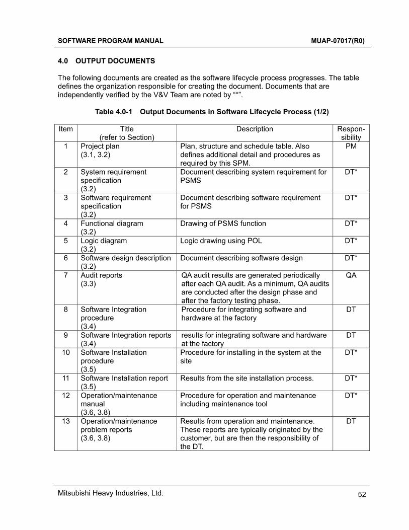
SOFTWARE PROGRAM MANUAL MUAP-07017(R0)
Mitsubishi Heavy Industries, Ltd. 52
4.0 OUTPUT DOCUMENTS The following documents are created as the software lifecycle process progresses. The table defines the organization responsible for creating the document. Documents that are independently verified by the V&V Team are noted by “*”.
Table 4.0-1 Output Documents in Software Lifecycle Process (1/2)
Item Title (refer to Section)
Description Respon-sibility
1 Project plan (3.1, 3.2)
Plan, structure and schedule table. Also defines additional detail and procedures as required by this SPM.
PM
2 System requirement specification (3.2)
Document describing system requirement for PSMS
DT*
3 Software requirement specification (3.2)
Document describing software requirement for PSMS
DT*
4 Functional diagram (3.2)
Drawing of PSMS function DT*
5 Logic diagram (3.2)
Logic drawing using POL DT*
6 Software design description(3.2)
Document describing software design DT*
7 Audit reports (3.3)
QA audit results are generated periodically after each QA audit. As a minimum, QA audits are conducted after the design phase and after the factory testing phase.
QA
8
Software Integration procedure (3.4)
Procedure for integrating software and hardware at the factory
DT
9 Software Integration reports(3.4)
results for integrating software and hardware at the factory
DT
10
Software Installation procedure (3.5)
Procedure for installing in the system at the site
DT*
11 Software Installation report (3.5)
Results from the site installation process. DT*
12 Operation/maintenance manual (3.6, 3.8)
Procedure for operation and maintenance including maintenance tool
DT*
13 Operation/maintenance problem reports (3.6, 3.8)
Results from operation and maintenance. These reports are typically originated by the customer, but are then the responsibility of the DT.
DT
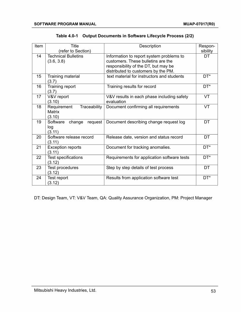
SOFTWARE PROGRAM MANUAL MUAP-07017(R0)
Mitsubishi Heavy Industries, Ltd. 53
Table 4.0-1 Output Documents in Software Lifecycle Process (2/2)
Item Title
(refer to Section) Description Respon-
sibility 14 Technical Bulletins
(3.6, 3.8) Information to report system problems to customers. These bulletins are the responsibility of the DT, but may be distributed to customers by the PM.
DT
15 Training material (3.7)
text material for instructors and students DT*
16 Training report (3.7)
Training results for record DT*
17 V&V report (3.10)
V&V results in each phase including safety evaluation
VT
18 Requirement Traceability Matrix (3.10)
Document confirming all requirements VT
19 Software change request log (3.11)
Document describing change request log DT
20 Software release record (3.11)
Release date, version and status record
DT
21
Exception reports (3.11)
Document for tracking anomalies. DT*
22 Test specifications (3.12)
Requirements for application software tests DT*
23 Test procedures (3.12)
Step by step details of test process DT
24 Test report (3.12)
Results from application software test DT*
DT: Design Team, VT: V&V Team, QA: Quality Assurance Organization, PM: Project Manager
SOFTWARE PROGRAM MANUAL MUAP-07017(R0)
Mitsubishi Heavy Industries, Ltd. 54
5.0 REFERENCES In this section, specific references referred in this SPM are provided. Other general applicable codes and regulatory guidance are described in MUAP-07004 and MUAP-07005.
1. NUREG-0800, BTP7-14 Revision 5 “Guidance on Software Reviews for Digital Computer-Based Instrumentation and Control System”, March 2007.
2. Topical Report MUAP-07005 R1, “Safety System Digital Platform –MELTAC-”. 3. Topical Report MUAP-07004 R1, “Safety I&C System Description and Design
Process”. 4. IEEE Std 603-1991, ”IEEE Standard Criteria for Safety System for Nuclear Power
Generating Stations”. 5. IEEE Std 7-4.3.2-2003, “IEEE Standard Criteria for Digital Computers in Safety
Systems of Nuclear Power Generating Stations”. 6. IEEE Std 1074-1995, ”IEEE Standard for Developing Software Lifecycle Processes”. 7. IEEE Std 830-1993, ”IEEE Recommended Practice for Software Requirements
Specifications”. 8. IEEE Std 730-1989, ”IEEE Standard for Software Quality Assurance Plans”. 9. IEEE Std 1028-1997, ”IEEE Standard for Software Reviews and Audits”.
10. IEEE Std 1228-1994, ”IEEE Standard for Software Safety Plan”. 11. IEEE Std 1012-1998 ”IEEE Standard for Software Verification and Validation”. 12. Regulatory Guide 1.169 Revision 0 “Configuration Management Plans for Digital
Computer Software Used in Safety System of Nuclear Power Plants”, September 1997.
13. IEEE Std 828-2005, ”IEEE Standard for Configuration Management Plans”. 14. IEEE Std 1042-1987, ”IEEE Guide for Software Configuration Management”. 15. IEEE Std 829-1983, ” IEEE Standard for Software Test Documentation”. 16. IEEE Std 1008-1987, ”IEEE Standard for Software Unit Testing”.
Related Documents