UPF-MANUAL-CM-001 URANIUM PROCESSING FACILITY CONSTRUCTION ELECTRICAL SAFETY MANUAL September 2017 | Revision 1 This document has been reviewed by a Y-12 DC / UCNI-RO and has been determined to be UNCLASSIFIED and contains no UCNI. This review does not constitute clearance for Public Release. Name:________________________ Date:__________ 09/20/17 RC-UPF DMC 09/20/17 08:01 Effective Date: 09/20/2017 Pg. 20 1/24/18 Reference documents corrected. Pen & Ink Change made on: ___________ Page(s) affected: _______ Reason for change: ________________________________________ ________________________________________________________ ________________________________________________________ _____________________________________________ __________ Requestor – Printed Name & Signature Date _____________________________________________ __________ Responsible Manager – Printed Name & Signature Date . . Bryan Leber . . 01/24/18 . . Scott Hayes . . 01/24/18 CFN document number corrected. Pg. 20, D-1 Pen & Ink Change made on: ___________ Page(s) affected: _______ Reason for change: ________________________________________ ________________________________________________________ ________________________________________________________ _____________________________________________ __________ Requestor – Printed Name & Signature Date _____________________________________________ __________ Responsible Manager – Printed Name & Signature Date . . 02/14/18 . . George Vellaringattu . . 02/14/18 . . Scott Hayes . . 02/14/18

Welcome message from author
This document is posted to help you gain knowledge. Please leave a comment to let me know what you think about it! Share it to your friends and learn new things together.
Transcript

UPF-MANUAL-CM-001
URANIUM PROCESSING FACILITY CONSTRUCTION ELECTRICAL SAFETY MANUAL
September 2017 | Revision 1
This document has been reviewed by a Y-12 DC / UCNI-RO and has been determined to be UNCLASSIFIED and contains no UCNI. This review does not constitute clearance for Public Release.
Name:________________________ Date:__________ 09/20/17
RC-UPF DMC 09/20/17 08:01
Effective Date: 09/20/2017
Pg. 201/24/18
Reference documents corrected.
Pen & Ink Change made on: ___________ Page(s) affected: _______
Reason for change: ________________________________________
________________________________________________________
________________________________________________________
_____________________________________________ __________
Requestor – Printed Name & Signature Date
_____________________________________________ __________
Responsible Manager – Printed Name & Signature Date
.
.Bryan Leber
.
.01/24/18
.
.Scott Hayes
.
.01/24/18
CFN document number corrected.
Pg. 20, D-1Pen & Ink Change made on: ___________ Page(s) affected: _______
Reason for change: ________________________________________
________________________________________________________
________________________________________________________
_____________________________________________ __________
Requestor – Printed Name & Signature Date
_____________________________________________ __________
Responsible Manager – Printed Name & Signature Date
.
.
02/14/18
.
.
George Vellaringattu
.
.
02/14/18
.
.
Scott Hayes
.
.
02/14/18
UPF-MANUAL-CM-001, Rev. 1September 2017
ii
URANIUM PROCESSING FACILITYCONSTRUCTION ELECTRICAL SAFETY MANUAL
September 2017
Prepared by the Uranium Processing Facility Project Teamof Consolidated Nuclear Security, LLCManagement & Operating Contractor
for theY-12 National Security Complex and Pantex Plant
under Contract No. DE NA0001942with the U.S. Department of Energy
National Nuclear Security Administration
UPF-MANUAL-CM-001, Rev. 1September 2017
iii
APPROVALS
Prepared by:
_____________________________________________________________Bryan Leber DateElectrical Field Engineer
Reviewed by:
_____________________________________________________________Edward Kelley DateProject ES&H Manager
Reviewed by:
_____________________________________________________________Mark Gibbs DateCNS Electrical Authority Having Jurisdiction
Approved by:
______________________________________________________________Matt Putinas DateUPF Manager of Construction
.
.09/19/17
.
.09/20/17
.
.09/20/17
Mark D (MG2) GibbsDigitally signed by Mark D (MG2) Gibbs DN: c=US, o=U.S. Government, ou=Department of Energy, ou=Y-12 National Security Complex, ou=CAs, ou=people, cn=Mark D (MG2) Gibbs Date: 2017.09.20 06:07:52 -04'00'
UPF-MANUAL-CM-001, Rev. 1September 2017
iv
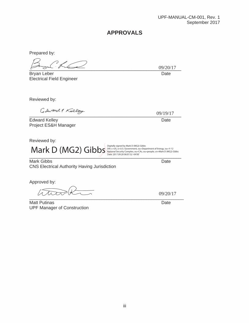
REVISION LOG
Revision Number Date Description of Change
TotalPages
AffectedPages
0 May 2017 Initial Issue All All
1 September 2017Incorporated reference to UPF-CP-226per CR: 25774-000-GCA-GAM-00336.Also added AHJ sign-off on Appendix F
39 13, 39
UPF-MANUAL-CM-001, Rev. 1September 2017
v
CONTENTS1.0 PURPOSE............................................................................................................................1
2.0 SCOPE.................................................................................................................................1
3.0 DEFINITIONS ......................................................................................................................2
4.0 RESPONSIBILITIES ............................................................................................................5
4.1 Lead Electrical Superintendent ..................................................................................5
4.2 Supervisors ................................................................................................................5
4.3 Qualified Electrical Personnel ....................................................................................6
4.4 Safety and Health Representative .............................................................................6
4.5 Project Engineer (or Designee)..................................................................................7
4.6 Training Manager .......................................................................................................7
5.0 PROCEDURE ......................................................................................................................7
5.1 General Requirements ...............................................................................................7
5.2 Work on or near Energized Circuits ...........................................................................8
5.3 Flash Hazard Protection...........................................................................................12
5.4 Energized Electrical Work Permit.............................................................................15
5.5 Powered Hand Tool Cords and Extension Cords ....................................................16
5.6 Inspection of Powered Hand Tools ..........................................................................18
5.7 Inspection of Protective Equipment..........................................................................18
5.8 Electrical Power and Lighting Circuits......................................................................19
5.9 Use of Proximity Testers ..........................................................................................19
5.10 UPF-Authorized Inspectors ......................................................................................19
6.0 RECORDS .........................................................................................................................20
7.0 REFERENCES...................................................................................................................20
UPF-MANUAL-CM-001, Rev. 1September 2017
vi
Appendices to UPF-MANUAL-CM-001APPENDIX A. ELECTRICAL SAFETY REQUIREMENTS .................................................. A-1
A1. 50 V to 150 V Line-to-Ground to 250 V Line-to-Line Alternating Current or Direct Current..................................................................................................... A-1
A2. 150 V Line-to-Ground to 600 V Line-to-Line Alternating Current or Direct Current ................................................................................................................... A-2
A3. 601 V to 15,000 V Line-to-Line Alternating Current ............................................... A-3
A4. 50 V to 150 V Line-to-Ground to 250 V Line-to-Line Alternating Current or Direct Current..................................................................................................... A-4
APPENDIX B. PROTECTIVE CLOTHING AND PERSONAL PROTECTIVE EQUIPMENT ................................................................................................................... B-1
B1. Protective Clothing Characteristics ........................................................................ B-1
B2. Protective Clothing and Personal Protective Equipment Flash Protection Criteria.................................................................................................................... B-2
APPENDIX C. FLASH PROTECTION BOUNDARY DISTANCE CALCULATIONS........... C-1
APPENDIX D. ENERGIZED ELECTRICAL WORK PERMIT ..............................................D-1
APPENDIX E. ENERGIZED ELECTRICAL WORK PERMIT INSTRUCTIONS .................. E-1
APPENDIX F. UPF OWNER’S INSPECTOR DELEGATE APPROVAL FORM.................. F-1

UPF-MANUAL-CM-001, Rev. 1September 2017
vii
TABLESTable 1. Working Distances ..........................................................................................................9
Table 2. Minimum Depth of Clear Distance at Electrical Equipment ..........................................11
Table 3. Approach Boundaries to Energized Electrical Conductors or Circuit Parts for Shock Protection.......................................................................................................................14
Table 4. Inspection Schedule and Marking Colors .....................................................................17
FIGURESFigure 1. Approach boundaries...................................................................................................13
UPF-MANUAL-CM-001, Rev. 1September 2017
viii
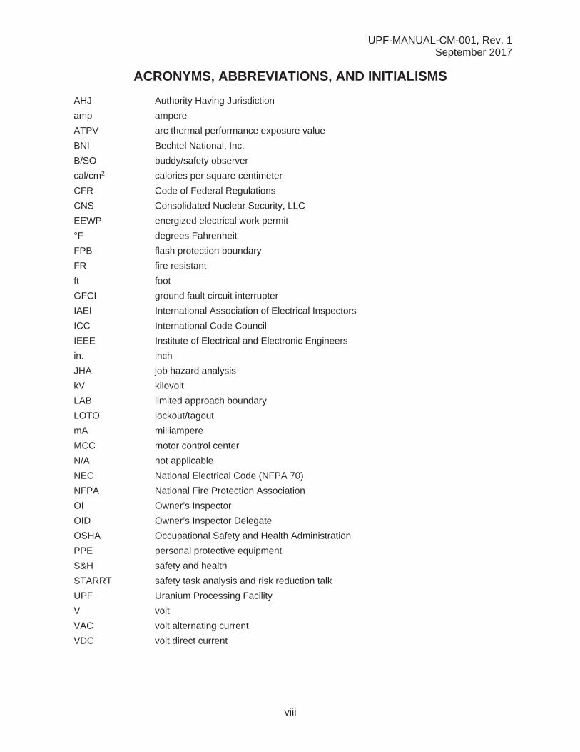
ACRONYMS, ABBREVIATIONS, AND INITIALISMS
AHJ Authority Having Jurisdiction
amp ampere
ATPV arc thermal performance exposure value
BNI Bechtel National, Inc.
B/SO buddy/safety observer
cal/cm2 calories per square centimeter
CFR Code of Federal Regulations
CNS Consolidated Nuclear Security, LLC
EEWP energized electrical work permit
°F degrees Fahrenheit
FPB flash protection boundary
FR fire resistant
ft foot
GFCI ground fault circuit interrupter
IAEI International Association of Electrical Inspectors
ICC International Code Council
IEEE Institute of Electrical and Electronic Engineers
in. inch
JHA job hazard analysis
kV kilovolt
LAB limited approach boundary
LOTO lockout/tagout
mA milliampere
MCC motor control center
N/A not applicable
NEC National Electrical Code (NFPA 70)
NFPA National Fire Protection Association
OI Owner’s Inspector
OID Owner’s Inspector Delegate
OSHA Occupational Safety and Health Administration
PPE personal protective equipment
S&H safety and health
STARRT safety task analysis and risk reduction talk
UPF Uranium Processing Facility
V volt
VAC volt alternating current
VDC volt direct current

UPF-MANUAL-CM-001, Rev. 1September 2017
1
1.0 PURPOSE
This manual provides responsibilities and requirements at the Uranium Processing Facility(UPF) for work performed on or near electrical energy sources—both temporary and permanent.The provisions of this manual apply to all work where there is a potential for workers to be exposed to a voltage of 50 volts (V) or more. The purpose is to ensure that all potential safety and health (S&H) hazards are identified and controlled, and are communicated to workersbefore they start working on or near electrical energy sources.
This manual ensures that all project work on or near electrical energy sources is performed in accordance with applicable electrical safety requirements, including the following National Fire Protection Association (NFPA) standard and Occupational Safety and Health Administration (OSHA) regulations in the Code of Federal Regulations (CFR):
NFPA 70E, Standard for Electrical Safety in the Workplace 2015
29 CFR 1926, “Safety and Health Regulations for Construction”
29 CFR 1910, “Occupational Safety and Health Standards”
§1910.137, “Electrical Protective Equipment”
§1910.147, “The Control of Hazardous Energy (Lockout/Tagout)”
§1910.269, “Electric Power Generation, Transmission, and Distribution,” Appendix B, “Working on Exposed Energized Parts”
§1910.303, “General”
§1910.304, “Wiring Design and Protection”
§1910.305, “Wiring Methods, Components, and Equipment for General Use”
§1910.332, “Training”
§1910.333, “Selection and Use of Work Practices”
2.0 SCOPE
This manual applies to all UPF personnel (including subcontractor personnel) during the construction of the UPF.
UPF-MANUAL-CM-001, Rev. 1September 2017
2
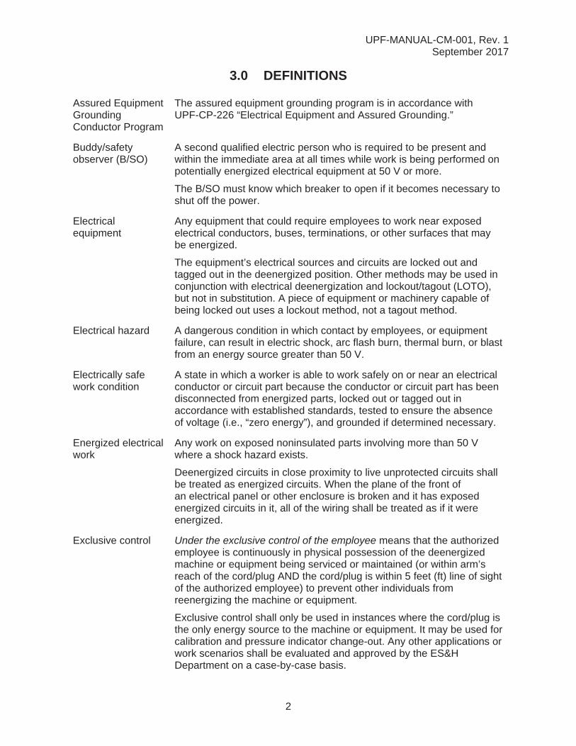
3.0 DEFINITIONS
Assured Equipment Grounding Conductor Program
The assured equipment grounding program is in accordance with UPF-CP-226 “Electrical Equipment and Assured Grounding.”
Buddy/safety observer (B/SO)
A second qualified electric person who is required to be present and within the immediate area at all times while work is being performed on potentially energized electrical equipment at 50 V or more.
The B/SO must know which breaker to open if it becomes necessary to shut off the power.
Electrical equipment
Any equipment that could require employees to work near exposed electrical conductors, buses, terminations, or other surfaces that may be energized.
The equipment’s electrical sources and circuits are locked out and tagged out in the deenergized position. Other methods may be used in conjunction with electrical deenergization and lockout/tagout (LOTO), but not in substitution. A piece of equipment or machinery capable of being locked out uses a lockout method, not a tagout method.
Electrical hazard A dangerous condition in which contact by employees, or equipment failure, can result in electric shock, arc flash burn, thermal burn, or blast from an energy source greater than 50 V.
Electrically safework condition
A state in which a worker is able to work safely on or near an electrical conductor or circuit part because the conductor or circuit part has been disconnected from energized parts, locked out or tagged out in accordance with established standards, tested to ensure the absence of voltage (i.e., “zero energy”), and grounded if determined necessary.
Energized electrical work
Any work on exposed noninsulated parts involving more than 50 Vwhere a shock hazard exists.
Deenergized circuits in close proximity to live unprotected circuits shall be treated as energized circuits. When the plane of the front of an electrical panel or other enclosure is broken and it has exposed energized circuits in it, all of the wiring shall be treated as if it were energized.
Exclusive control Under the exclusive control of the employee means that the authorized employee is continuously in physical possession of the deenergized machine or equipment being serviced or maintained (or within arm’sreach of the cord/plug AND the cord/plug is within 5 feet (ft) line of sight of the authorized employee) to prevent other individuals from reenergizing the machine or equipment.
Exclusive control shall only be used in instances where the cord/plug is the only energy source to the machine or equipment. It may be used for calibration and pressure indicator change-out. Any other applications or work scenarios shall be evaluated and approved by the ES&HDepartment on a case-by-case basis.
UPF-MANUAL-CM-001, Rev. 1September 2017
3
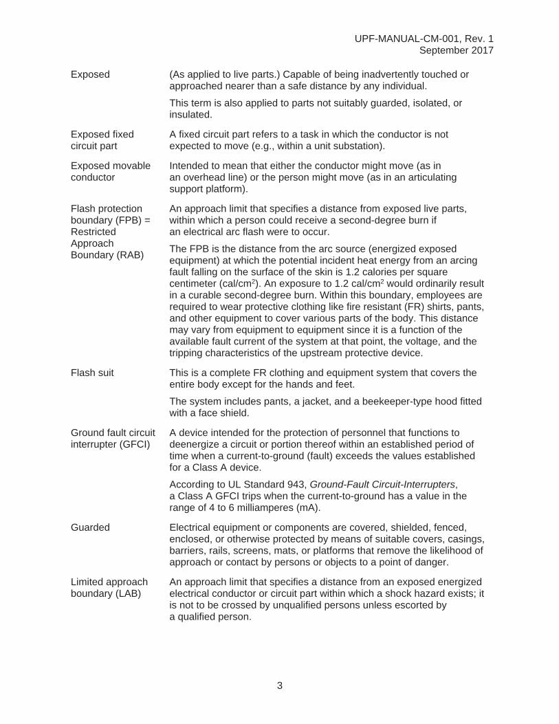
Exposed (As applied to live parts.) Capable of being inadvertently touched or approached nearer than a safe distance by any individual.
This term is also applied to parts not suitably guarded, isolated, or insulated.
Exposed fixed circuit part
A fixed circuit part refers to a task in which the conductor is not expected to move (e.g., within a unit substation).
Exposed movable conductor
Intended to mean that either the conductor might move (as in an overhead line) or the person might move (as in an articulating support platform).
Flash protection boundary (FPB) =Restricted Approach Boundary (RAB)
An approach limit that specifies a distance from exposed live parts, within which a person could receive a second-degree burn if an electrical arc flash were to occur.
The FPB is the distance from the arc source (energized exposed equipment) at which the potential incident heat energy from an arcing fault falling on the surface of the skin is 1.2 calories per square centimeter (cal/cm2). An exposure to 1.2 cal/cm2 would ordinarily result in a curable second-degree burn. Within this boundary, employees are required to wear protective clothing like fire resistant (FR) shirts, pants, and other equipment to cover various parts of the body. This distance may vary from equipment to equipment since it is a function of the available fault current of the system at that point, the voltage, and the tripping characteristics of the upstream protective device.
Flash suit This is a complete FR clothing and equipment system that covers the entire body except for the hands and feet.
The system includes pants, a jacket, and a beekeeper-type hood fitted with a face shield.
Ground fault circuit interrupter (GFCI)
A device intended for the protection of personnel that functions to deenergize a circuit or portion thereof within an established period of time when a current-to-ground (fault) exceeds the values established for a Class A device.
According to UL Standard 943, Ground-Fault Circuit-Interrupters,a Class A GFCI trips when the current-to-ground has a value in the range of 4 to 6 milliamperes (mA).
Guarded Electrical equipment or components are covered, shielded, fenced, enclosed, or otherwise protected by means of suitable covers, casings, barriers, rails, screens, mats, or platforms that remove the likelihood of approach or contact by persons or objects to a point of danger.
Limited approach boundary (LAB)
An approach limit that specifies a distance from an exposed energized electrical conductor or circuit part within which a shock hazard exists; it is not to be crossed by unqualified persons unless escorted by a qualified person.

UPF-MANUAL-CM-001, Rev. 1September 2017
4
Lockout/tagout (LOTO)
The placement of a lock and tag on an energy-isolating device to prevent the unexpected energizing, start-up, or release of stored energy from equipment or machines that could cause injury to employees.
Methods of LOTO include
a) locking and tagging the entire electrical supply or individual switches, or
b) locking or blocking internal moving parts in resting position, or
c) conducting both a) and b) if the potential exists that performing one or the other does not control all energy sources.
Qualified electrical person
A qualified person trained and knowledgeable of the construction and operation of equipment or a specific work method, and trained torecognize and avoid the electrical hazards that might be present with respect to that equipment or work method.
Qualified personnel are specifically trained in the requirements contained in NFPA 70E and 29 CFR 1910.332. Such persons shall also be familiar with the proper use of special precautionary techniques, personal protective equipment (PPE), insulating/shielding materials, and insulating tools and test equipment. Qualified persons permitted to work within limited approach boundaries (LABs) of exposed energized conductors and circuit parts shall, at a minimum, be additionally trained in all of the following:
The skills and techniques necessary to distinguish exposed energized electrical parts from other parts of electrical equipment
The skills and techniques necessary to determine the nominal voltage of exposed energized parts
The approach distances specified in Table 1 and Table 2 in Section 5.2 and the corresponding voltages to which the qualified person will be exposed
The decision-making process necessary to determine the degree and extent of the hazard, and the PPE and job planning necessary to perform the task safely
An employee who is undergoing on-the-job training and, in the course of such training, has demonstrated an ability to perform duties safely commensurate with the level of training received under the direct supervision of a qualified person shall be considered to be a qualified person for the performance of those duties.
Restricted approach boundary
An approach limit that specifies a distance from an exposed energized electrical conductor or circuit part within which there is an increased risk of shock due to electrical arc-over combined with inadvertent movement, for personnel working in close proximity to the energized electrical conductor or circuit part; it is to be crossed by only qualified persons.
UPF-MANUAL-CM-001, Rev. 1September 2017
5
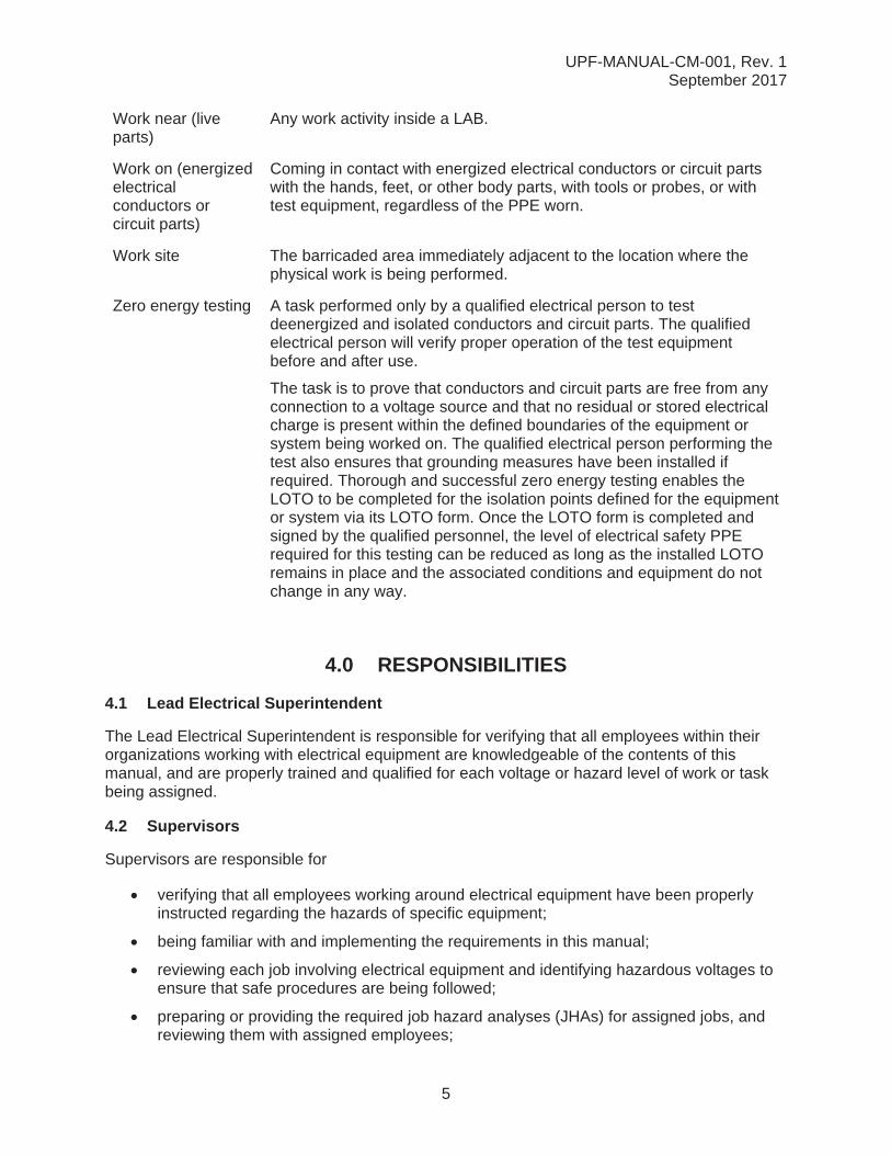
Work near (live parts)
Any work activity inside a LAB.
Work on (energized electrical conductors or circuit parts)
Coming in contact with energized electrical conductors or circuit parts with the hands, feet, or other body parts, with tools or probes, or with test equipment, regardless of the PPE worn.
Work site The barricaded area immediately adjacent to the location where the physical work is being performed.
Zero energy testing A task performed only by a qualified electrical person to test deenergized and isolated conductors and circuit parts. The qualified electrical person will verify proper operation of the test equipment before and after use.
The task is to prove that conductors and circuit parts are free from any connection to a voltage source and that no residual or stored electrical charge is present within the defined boundaries of the equipment or system being worked on. The qualified electrical person performing the test also ensures that grounding measures have been installed if required. Thorough and successful zero energy testing enables the LOTO to be completed for the isolation points defined for the equipmentor system via its LOTO form. Once the LOTO form is completed and signed by the qualified personnel, the level of electrical safety PPE required for this testing can be reduced as long as the installed LOTO remains in place and the associated conditions and equipment do not change in any way.
4.0 RESPONSIBILITIES
4.1 Lead Electrical Superintendent
The Lead Electrical Superintendent is responsible for verifying that all employees within their organizations working with electrical equipment are knowledgeable of the contents of this manual, and are properly trained and qualified for each voltage or hazard level of work or task being assigned.
4.2 Supervisors
Supervisors are responsible for
verifying that all employees working around electrical equipment have been properly instructed regarding the hazards of specific equipment;
being familiar with and implementing the requirements in this manual;
reviewing each job involving electrical equipment and identifying hazardous voltages to ensure that safe procedures are being followed;
preparing or providing the required job hazard analyses (JHAs) for assigned jobs, and reviewing them with assigned employees;

UPF-MANUAL-CM-001, Rev. 1September 2017
6
submitting JHAs to the S&H representative for review and completion;
verifying that all assigned employees are trained and qualified for the level of work involved and that the employees do not perform work alone on energized circuits or equipment at 50 V or more.
ensuring that safety equipment necessary to perform work tasks required by this manual is identified and provided in proper working order;
verifying that the PPE selected for a work task meets the intent of this manual;
completing a safety task analysis and risk reduction talk (STARRT) card and JHA for energized work;
determining the limited approach boundary (LAB) and the flash protection boundary (FPB);
preparing the energized electrical work permits (EEWPs);
ensuring that protective shields are installed where appropriate to prevent workers from inadvertently coming in contact with energized equipment; and
maintaining the EEWP log.
4.3 Qualified Electrical Personnel
All qualified electrical personnel are responsible for
complying with this manual;
being trained and qualified for the level of work involved;
NOTE: Do not work alone on energized circuits or equipment at 50V or more.
participating in the development and/or preparation of the JHA for the assigned job, as directed by the supervisor;
reporting any unsafe practices, both to the individual involved and to their supervisor;
demonstrating competence in the skills, knowledge, and techniques necessary todistinguish exposed energized parts from other parts of the equipment, and demonstrating they have received training to recognize and avoid the hazards involved (see NFPA 70E); and
demonstrating competence in the proper use of special precautionary techniques, PPE, insulating and shielding materials, and insulated tools for working on or near exposed energized parts of electrical equipment.
4.4 Safety and Health Representative
The S&H representative is responsible for
reviewing and, if applicable, approving JHAs and EEWPs.
assisting in the development of JHAs and EEWPs, when requested.
reviewing assigned electrical PPE, when requested.
providing field electrical safety oversight.

UPF-MANUAL-CM-001, Rev. 1September 2017
7
4.5 Project Engineer (or Designee)
The project engineer or designee is responsible for providing all calculations for arc flash and approach boundaries in accordance with Institute of Electrical and Electronic Engineers (IEEE) Standard 1584, Guide for Performing Arc-Flash Hazard Calculations.
4.6 Training Manager
The training manager is responsible for
tracking and maintaining all electrical safety training records, andmaintaining the training database.
5.0 PROCEDURE
5.1 General Requirements
The requirements in this section shall apply to all employees who perform tasks that could expose them to electrical shock hazards that are not reduced to a safe level through the applicable electrical installation requirements.
Areas to which access is limited by LAB requirements will be released after protection shields are installed and no exposed energized components remain to pose a hazard.
The organization performing work within the LAB or FPB shall also follow these requirements:
A. The assigned employees and supervisor must complete a pre-job STARRT card and JHA to communicate known hazards to each employee in the designated work area. The STARRT card and JHA are required on all work activities. All assigned employees must sign the STARRT card and JHA, acknowledging their review before starting work.
B. Red and black “DANGER” barrier tape is required to be installed as a visible barrier to preclude unauthorized entry into the LAB or FPB from all accessible directions. Additionally, a sign or tag identifying the hazard shall be present at the barrier.
C. The assigned employees shall ensure all others in the vicinity are kept outside the LAB and FPB when work is being performed. The assigned employees may allow qualified employees and escorted employees to cross the LAB and FPB when it is safe to do so. Two qualified electrical persons are required when testing is being performed, and all personnel inside the LAB or FPB are required to wear the same level of PPE.
D. The employee performing the actual hands-on work must be a qualified electrical person. Other employees assigned to the scope of work cannot perform the work in the LAB and/or the FPB.
E. An ABC-rated fire extinguisher must be readily available at the work site. This manualdefines the work site as the barricaded area immediately adjacent to the location where the physical work is being performed.
F. The work area must be dry, adequately illuminated, and free of obstructions and debris that may become a hazard or interfere with the work activity.
UPF-MANUAL-CM-001, Rev. 1September 2017
8
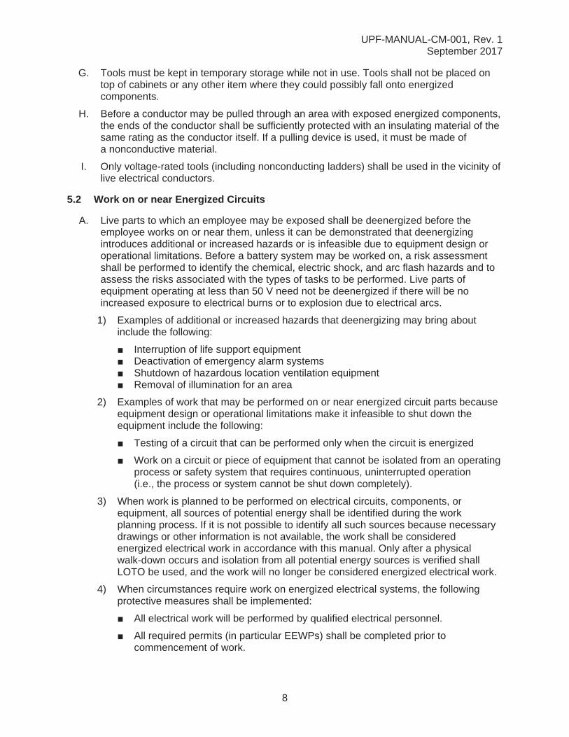
G. Tools must be kept in temporary storage while not in use. Tools shall not be placed on top of cabinets or any other item where they could possibly fall onto energized components.
H. Before a conductor may be pulled through an area with exposed energized components, the ends of the conductor shall be sufficiently protected with an insulating material of the same rating as the conductor itself. If a pulling device is used, it must be made of a nonconductive material.
I. Only voltage-rated tools (including nonconducting ladders) shall be used in the vicinity of live electrical conductors.
5.2 Work on or near Energized Circuits
A. Live parts to which an employee may be exposed shall be deenergized before the employee works on or near them, unless it can be demonstrated that deenergizing introduces additional or increased hazards or is infeasible due to equipment design or operational limitations. Before a battery system may be worked on, a risk assessment shall be performed to identify the chemical, electric shock, and arc flash hazards and to assess the risks associated with the types of tasks to be performed. Live parts ofequipment operating at less than 50 V need not be deenergized if there will be no increased exposure to electrical burns or to explosion due to electrical arcs.
1) Examples of additional or increased hazards that deenergizing may bring about include the following:
Interruption of life support equipmentDeactivation of emergency alarm systemsShutdown of hazardous location ventilation equipmentRemoval of illumination for an area
2) Examples of work that may be performed on or near energized circuit parts becauseequipment design or operational limitations make it infeasible to shut down the equipment include the following:
Testing of a circuit that can be performed only when the circuit is energized
Work on a circuit or piece of equipment that cannot be isolated from an operating process or safety system that requires continuous, uninterrupted operation(i.e., the process or system cannot be shut down completely).
3) When work is planned to be performed on electrical circuits, components, or equipment, all sources of potential energy shall be identified during the work planning process. If it is not possible to identify all such sources because necessary drawings or other information is not available, the work shall be considered energized electrical work in accordance with this manual. Only after a physical walk-down occurs and isolation from all potential energy sources is verified shall LOTO be used, and the work will no longer be considered energized electrical work.
4) When circumstances require work on energized electrical systems, the following protective measures shall be implemented:
All electrical work will be performed by qualified electrical personnel.
All required permits (in particular EEWPs) shall be completed prior to commencement of work.

UPF-MANUAL-CM-001, Rev. 1September 2017
9
All tools and inspection equipment shall be insulated and rated for the voltage of the energized equipment.
Only PPE that is designed and rated for the voltage of the energized equipment shall be used.
B. Two qualified electrical persons shall be present and within the immediate area at all times while work is being performed on potentially energized electrical equipment at50 V or more. Use of an intercom or radio is not an acceptable substitute for this requirement. This requirement does not apply to the use of electrical portable hand tools (e.g., drills, saws), or completely enclosed electronic equipment of conventional type (e.g., computers, copiers, fax machines). The second person (i.e., the B/SO) must be present and within the immediate area while the work is being performed.
1) The B/SO must know which breaker to open if it becomes necessary to shut off thepower.
2) One employee can work alone if performing a visual inspection or monitoringfunctions only, the employee shall not break the plane of the FPB.
C. When working on energized devices, the assigned employee will, when possible, work with one hand, with the other hand not touching a grounded item.
D. All work in an electrical panel or any other enclosure that has energized circuits with exposed noninsulated parts shall be considered energized work if the plane of the front of the panel or enclosure is broken during the course of that work activity with tools or body parts.
E. When electrical work is to be performed in confined or enclosed work spaces (e.g., manholes, vaults), the following rules must be followed:
1) Protective shields, barriers, and/or insulating materials shall be used to preventinadvertent contact with exposed energized parts over 50 V.
2) Doors and hinged panels that are of sufficient weight or can be “moved” by the windso as to push an employee into an exposed electrical circuit shall be secured toprevent their movement.
3) A Confined Space Entry Permit evaluation must be performed prior to issuinga permit and entering the confined space.
4) Safe working distances must be maintained as specified in Table 1.
Table 1. Working Distances
Nominal Voltage to GroundMinimum Clear Distance
Condition 1 Condition 2 Condition 351–150 V 3 ft 3 ft 3 ft
151–600 V 3 ft 3½ ft 4 ft
Note: Use a greater distance (FPB or LAB) to trigger the need for PPE.
UPF-MANUAL-CM-001, Rev. 1September 2017
10
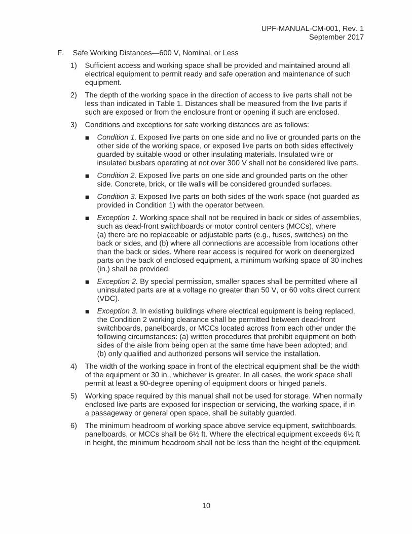
F. Safe Working Distances—600 V, Nominal, or Less
1) Sufficient access and working space shall be provided and maintained around allelectrical equipment to permit ready and safe operation and maintenance of suchequipment.
2) The depth of the working space in the direction of access to live parts shall not beless than indicated in Table 1. Distances shall be measured from the live parts ifsuch are exposed or from the enclosure front or opening if such are enclosed.
3) Conditions and exceptions for safe working distances are as follows:
Condition 1. Exposed live parts on one side and no live or grounded parts on theother side of the working space, or exposed live parts on both sides effectively guarded by suitable wood or other insulating materials. Insulated wire or insulated busbars operating at not over 300 V shall not be considered live parts.
Condition 2. Exposed live parts on one side and grounded parts on the other side. Concrete, brick, or tile walls will be considered grounded surfaces.
Condition 3. Exposed live parts on both sides of the work space (not guarded as provided in Condition 1) with the operator between.
Exception 1. Working space shall not be required in back or sides of assemblies, such as dead-front switchboards or motor control centers (MCCs), where (a) there are no replaceable or adjustable parts (e.g., fuses, switches) on the back or sides, and (b) where all connections are accessible from locations other than the back or sides. Where rear access is required for work on deenergized parts on the back of enclosed equipment, a minimum working space of 30 inches(in.) shall be provided.
Exception 2. By special permission, smaller spaces shall be permitted where all uninsulated parts are at a voltage no greater than 50 V, or 60 volts direct current (VDC).
Exception 3. In existing buildings where electrical equipment is being replaced, the Condition 2 working clearance shall be permitted between dead-front switchboards, panelboards, or MCCs located across from each other under thefollowing circumstances: (a) written procedures that prohibit equipment on both sides of the aisle from being open at the same time have been adopted; and(b) only qualified and authorized persons will service the installation.
4) The width of the working space in front of the electrical equipment shall be the widthof the equipment or 30 in., whichever is greater. In all cases, the work space shallpermit at least a 90-degree opening of equipment doors or hinged panels.
5) Working space required by this manual shall not be used for storage. When normallyenclosed live parts are exposed for inspection or servicing, the working space, if ina passageway or general open space, shall be suitably guarded.
6) The minimum headroom of working space above service equipment, switchboards,panelboards, or MCCs shall be 6½ ft. Where the electrical equipment exceeds 6½ ftin height, the minimum headroom shall not be less than the height of the equipment.
UPF-MANUAL-CM-001, Rev. 1September 2017
11
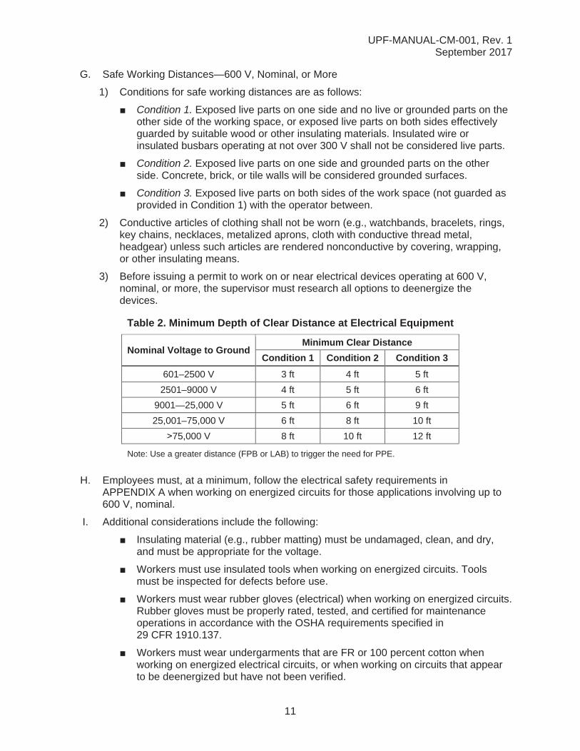
G. Safe Working Distances—600 V, Nominal, or More
1) Conditions for safe working distances are as follows:
Condition 1. Exposed live parts on one side and no live or grounded parts on the other side of the working space, or exposed live parts on both sides effectively guarded by suitable wood or other insulating materials. Insulated wire or insulated busbars operating at not over 300 V shall not be considered live parts.
Condition 2. Exposed live parts on one side and grounded parts on the other side. Concrete, brick, or tile walls will be considered grounded surfaces.
Condition 3. Exposed live parts on both sides of the work space (not guarded as provided in Condition 1) with the operator between.
2) Conductive articles of clothing shall not be worn (e.g., watchbands, bracelets, rings, key chains, necklaces, metalized aprons, cloth with conductive thread metal, headgear) unless such articles are rendered nonconductive by covering, wrapping, or other insulating means.
3) Before issuing a permit to work on or near electrical devices operating at 600 V, nominal, or more, the supervisor must research all options to deenergize thedevices.
Table 2. Minimum Depth of Clear Distance at Electrical Equipment
Nominal Voltage to GroundMinimum Clear Distance
Condition 1 Condition 2 Condition 3601–2500 V 3 ft 4 ft 5 ft
2501–9000 V 4 ft 5 ft 6 ft
9001—25,000 V 5 ft 6 ft 9 ft
25,001–75,000 V 6 ft 8 ft 10 ft
75,000 V 8 ft 10 ft 12 ft
Note: Use a greater distance (FPB or LAB) to trigger the need for PPE.
H. Employees must, at a minimum, follow the electrical safety requirements in APPENDIX A when working on energized circuits for those applications involving up to 600 V, nominal.
I. Additional considerations include the following:
Insulating material (e.g., rubber matting) must be undamaged, clean, and dry, and must be appropriate for the voltage.
Workers must use insulated tools when working on energized circuits. Tools must be inspected for defects before use.
Workers must wear rubber gloves (electrical) when working on energized circuits. Rubber gloves must be properly rated, tested, and certified for maintenance operations in accordance with the OSHA requirements specified in 29 CFR 1910.137.
Workers must wear undergarments that are FR or 100 percent cotton whenworking on energized electrical circuits, or when working on circuits that appear to be deenergized but have not been verified.
UPF-MANUAL-CM-001, Rev. 1September 2017
12
Workers must always wear shoes with nonconductive soles when working on energized circuits.
All exposed electrical sources must be covered to prevent workers from touchingthem.
J. The requirements of this manual do not apply to tasks such as those listed below:
1) Changing out light bulbs, as long as there are no exposed wires, the only work on the circuit is to change a bulb out in an undamaged permanent fixture, and the bulb is not a high-temperature quartz iodide bulb. The quartz iodide (high-wattage halogen) bulbs, when energized, are instantaneously 350 degrees Fahrenheit (°F)and require deenergizing the fixture before the bulb may be changed out. Severe burns may result if the bulb is put into an energized circuit with bare hands. Where practical, the light fixture should be turned off before changing the bulb. This will require a lockout if exclusive control cannot be ensured.
2) The changing of fuses that are designed to break contact with the energized circuit before physical contact can be made with any part of the fuse.
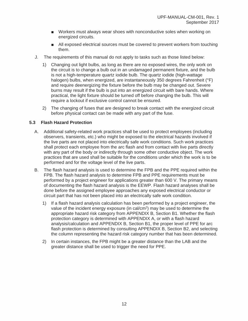
5.3 Flash Hazard Protection
A. Additional safety-related work practices shall be used to protect employees (including observers, transients, etc.) who might be exposed to the electrical hazards involved if the live parts are not placed into electrically safe work conditions. Such work practices shall protect each employee from the arc flash and from contact with live parts directly with any part of the body or indirectly through some other conductive object. The work practices that are used shall be suitable for the conditions under which the work is to be performed and for the voltage level of the live parts.
B. The flash hazard analysis is used to determine the FPB and the PPE required within the FPB. The flash hazard analysis to determine FPB and PPE requirements must be performed by a project engineer for applications greater than 600 V. The primary means of documenting the flash hazard analysis is the EEWP. Flash hazard analyses shall be done before the assigned employee approaches any exposed electrical conductor or circuit part that has not been placed into an electrically safe work condition.
1) If a flash hazard analysis calculation has been performed by a project engineer, the value of the incident energy exposure (in cal/cm2) may be used to determine the appropriate hazard risk category from APPENDIX B, Section B1. Whether the flash protection category is determined with APPENDIX A, or with a flash hazard analysis/calculation and APPENDIX B, Section B1, the proper level of PPE for arc flash protection is determined by consulting APPENDIX B, Section B2, and selecting the column representing the hazard risk category number that has been determined.
2) In certain instances, the FPB might be a greater distance than the LAB and the greater distance shall be used to trigger the need for PPE.

UPF-MANUAL-CM-001, Rev. 1September 2017
13
C. NFPA 70E specifies the requirement of PPE for employees within the FPB. All parts of the body that may be exposed to the arc flash need to be covered by the appropriate type and quality of PPE. The entire PPE set may be comprised of FR helmet or headgear, face shield, safety glasses, gloves, shoes, etc. depending upon the magnitude of the arc energy.
The FPB shall be calculated by a qualified project engineer in accordance with thegeneral formula in APPENDIX C. The protective clothing shall limit the incident energy reaching the chest/face of the employee to less than 1.2 cal/cm2. FR clothing provides thermal insulation and is also self-extinguishing. Protective clothing is rated in cal/cm2.
D. Figure 1 depicts a representation of approach boundaries in relation to PPE.
Figure 1. Approach boundaries
UPF-MANUAL-CM-001, Rev. 1September 2017
14
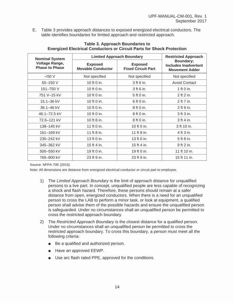
E. Table 3 provides approach distances to exposed energized electrical conductors. The table identifies boundaries for limited approach and restricted approach.
Table 3. Approach Boundaries to Energized Electrical Conductors or Circuit Parts for Shock Protection
Nominal System Voltage Range, Phase to Phase
Limited Approach Boundary Restricted Approach Boundary;
Includes Inadvertent Movement Adder
Exposed Movable Conductor
Exposed Fixed Circuit Part
<50 V Not specified Not specified Not specified
50–150 V 10 ft 0 in. 3 ft 6 in. Avoid Contact
151–750 V 10 ft 0 in. 3 ft 6 in. 1 ft 0 in.
751 V–15 kV 10 ft 0 in. 5 ft 0 in. 2 ft 2 in.
15.1–36 kV 10 ft 0 in. 6 ft 0 in. 2 ft 7 in.
36.1–46 kV 10 ft 0 in. 8 ft 0 in. 2 ft 9 in.
46.1–72.5 kV 10 ft 0 in. 8 ft 0 in. 3 ft 3 in.
72.6–121 kV 10 ft 8 in. 8 ft 0 in. 3 ft 4 in.
138–145 kV 11 ft 0 in. 10 ft 0 in. 3 ft 10 in.
161–169 kV 11 ft 8 in. 11 ft 8 in. 4 ft 3 in.
230–242 kV 13 ft 0 in. 13 ft 0 in. 5 ft 8 in.
345–362 kV 15 ft 4 in. 15 ft 4 in. 9 ft 2 in.
500–550 kV 19 ft 0 in. 19 ft 0 in. 11 ft 10 in.
765–800 kV 23 ft 9 in. 23 ft 9 in. 15 ft 11 in.
Source: NFPA 70E (2015)
Note: All dimensions are distance from energized electrical conductor or circuit part to employee.
1) The Limited Approach Boundary is the limit of approach distance for unqualifiedpersons to a live part. In concept, unqualified people are less capable of recognizinga shock and flash hazard. Therefore, these persons should remain at a saferdistance from open, energized conductors. When there is a need for an unqualifiedperson to cross the LAB to perform a minor task, or look at equipment, a qualifiedperson shall advise them of the possible hazards and ensure the unqualified personis safeguarded. Under no circumstances shall an unqualified person be permitted tocross the restricted approach boundary.
2) The Restricted Approach Boundary is the closest distance for a qualified person.Under no circumstances shall an unqualified person be permitted to cross therestricted approach boundary. To cross this boundary, a person must meet all thefollowing criteria:
Be a qualified and authorized person.
Have an approved EEWP.
Use arc flash rated PPE, approved for the conditions.
UPF-MANUAL-CM-001, Rev. 1September 2017
15
Position the body in a way that minimizes risk of inadvertent contact in some instances. Work outside the restricted approach boundary (but within the person’s reach) may be classified as restricted work if, in the judgment of the personnel involved, conductive objects or ungrounded body parts could make unintentional contact.
3) The Restricted Space is the area within the restricted approach boundary wherepersonnel could be exposed to energized conductor or circuit part.
To cross this boundary and enter the restricted space shall be considered the sameas making contact with exposed energized conductors or circuit parts. To cross therestricted space, the qualified person must do the following:
Have specified training to work on energized conductors or circuit parts.
Have a documented plan that justifies the need to work inside the restrictedapproach boundary.
Perform a flash hazard risk analysis.
Have both the documented justification plan and the flash hazard risk analysisapproved by the site manager.
F. Test equipment, tools, safety equipment, PPE, approvals, attendance, and backup person requirements shall be used in accordance with APPENDIX A.
G. Electrical equipment, such as switchboards, panel boards, industrial control panels, meter socket enclosures, and motor control centers, that are in other than dwelling occupancies, and that are likely to require examination, adjustment, servicing, or maintenance while energized, shall be field marked to warn qualified persons of potential electric arc flash hazards. The marking shall be located so as to be clearly visible to qualified persons before examination, adjustment, servicing, or maintenance of the equipment. Equipment shall be field marked with a label containing the available incident energy or required level of PPE.
5.4 Energized Electrical Work Permit
A. Working on or near live parts and/or exposed energized electrical equipment requires the completion of an EEWP (see APPENDIX D), and shall only be permitted after the work group has determined that the energy isolation cannot be reasonably accomplished or the needed data can best be obtained while the circuit is energized. Examples of these types of work include scheme checks, loop checks, control system troubleshooting, and testing.
B. If the exposed energized components cannot be electrically isolated, the field engineer or their designee shall:
1) Complete, as applicable, a STARRT card or JHA for each scope based on specific configurations. The STARRT card and JHA are required on all work activities, except a STARRT card and JHA (in lieu of the JHA) are required when voltages exceed 600 volts alternating current (VAC) and 250 VDC.
2) Determine the LAB, FPB, and PPE requirements.
3) Mitigate hazards, when feasible, by installing protective shields and/or barriers where appropriate to prevent accidental contact by employees, materials, and tools with exposed energized equipment.

UPF-MANUAL-CM-001, Rev. 1September 2017
16
4) Verify appropriate PPE and tools are used by the employees.
5) Prepare the EEWP in accordance with APPENDIX E.
C. The following items, at a minimum, shall be documented on the EEWP for energized electrical work:
1) Description of the circuits and equipment to be worked on, and their location
2) Justification for why the work must be performed in an energized condition
3) Description of the safe work practices to be employed
4) Determination of the LAB for exposed energized parts for unqualified employees
5) Determination of restricted and prohibitive approach boundaries for qualifiedemployees
6) Results of the flash hazard analysis
7) Approach boundary for flash protection (FPB)
8) Identification of necessary PPE to safely perform the assigned task
9) Barriers employed to restrict the access of unqualified persons from the work area
10) Evidence of completion of a job briefing, including a discussion of any job-specifichazards
11) Energized work approval signature(s)
D. Work performed by qualified electricians within the LAB of energized electrical conductors or circuit parts related to tasks (i.e., testing, troubleshooting, voltage measuring [typically diagnostic work], or visual inspection) may be performed without an EEWP, using Alternate Energized Work Procedures including the use of flash hazard analysis, safe work practices and with the appropriate PPE. The PPE will be identified on the STARRT card or detailed work package.
5.5 Powered Hand Tool Cords and Extension Cords
A. Before initial use and prior to each use thereafter; attachment plugs, receptacles, cover plates, and cord connectors are visually inspected by the employee who is assigned to use the equipment. If any of the conditions listed below exist, the equipment is tagged with a “DO NOT USE” tag and returned to the tool crib for repair or disposal:
Breaks, damage, or cracks exposing live components or loss of insulation on electrical conductors or wiring
Missing cover plates
Terminations with stray strands or loose terminals
Missing, loose, altered, or damaged blades, pins, or contacts
Frayed or damaged cords
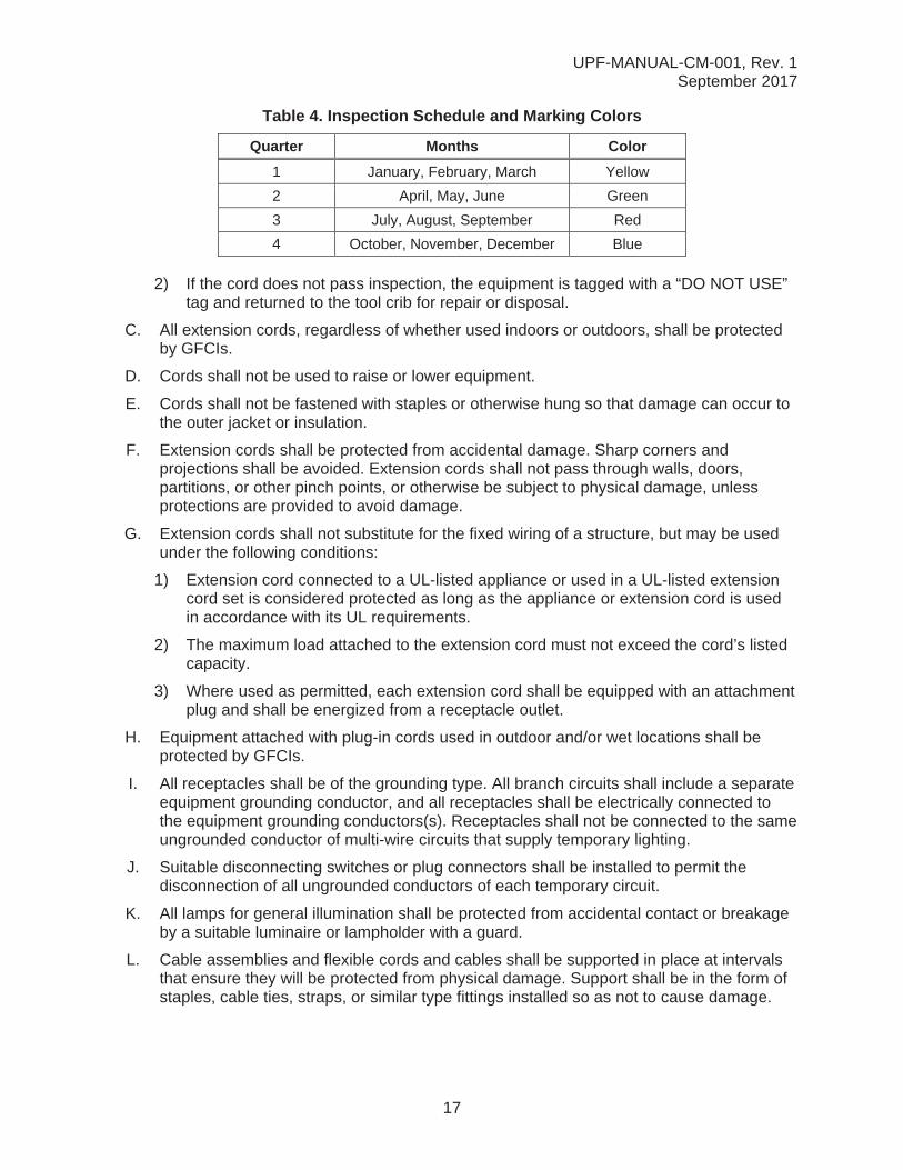
B. In addition to the inspection by the assigned employee, a qualified electrical person will conduct quarterly cord inspections.
1) If the cord passes inspection, the qualified electrical person will affix the applicablecolor tape on the side rail in accordance with Table 4:
UPF-MANUAL-CM-001, Rev. 1September 2017
17
Table 4. Inspection Schedule and Marking Colors
Quarter Months Color1 January, February, March Yellow
2 April, May, June Green
3 July, August, September Red
4 October, November, December Blue
2) If the cord does not pass inspection, the equipment is tagged with a “DO NOT USE”tag and returned to the tool crib for repair or disposal.
C. All extension cords, regardless of whether used indoors or outdoors, shall be protected by GFCIs.
D. Cords shall not be used to raise or lower equipment.
E. Cords shall not be fastened with staples or otherwise hung so that damage can occur tothe outer jacket or insulation.
F. Extension cords shall be protected from accidental damage. Sharp corners andprojections shall be avoided. Extension cords shall not pass through walls, doors,partitions, or other pinch points, or otherwise be subject to physical damage, unlessprotections are provided to avoid damage.
G. Extension cords shall not substitute for the fixed wiring of a structure, but may be used under the following conditions:
1) Extension cord connected to a UL-listed appliance or used in a UL-listed extensioncord set is considered protected as long as the appliance or extension cord is usedin accordance with its UL requirements.
2) The maximum load attached to the extension cord must not exceed the cord’s listedcapacity.
3) Where used as permitted, each extension cord shall be equipped with an attachmentplug and shall be energized from a receptacle outlet.
H. Equipment attached with plug-in cords used in outdoor and/or wet locations shall be protected by GFCIs.
I. All receptacles shall be of the grounding type. All branch circuits shall include a separate equipment grounding conductor, and all receptacles shall be electrically connected to the equipment grounding conductors(s). Receptacles shall not be connected to the same ungrounded conductor of multi-wire circuits that supply temporary lighting.
J. Suitable disconnecting switches or plug connectors shall be installed to permit the disconnection of all ungrounded conductors of each temporary circuit.
K. All lamps for general illumination shall be protected from accidental contact or breakage by a suitable luminaire or lampholder with a guard.
L. Cable assemblies and flexible cords and cables shall be supported in place at intervals that ensure they will be protected from physical damage. Support shall be in the form of staples, cable ties, straps, or similar type fittings installed so as not to cause damage.
UPF-MANUAL-CM-001, Rev. 1September 2017
18
5.6 Inspection of Powered Hand Tools
A. All required tests shall be performed before first use; before equipment is returned to service following any repairs; before equipment is used after any incident which can be reasonably suspected to have caused damage (e.g., when a cord set is run over); and at intervals not to exceed three months.
B. If any of the conditions listed below exist, the equipment must be tagged with a “DO NOT USE” tag and returned to the tool crib for repair or disposal:
1) Breaks, damage, or cracks exposing energized electrical parts2) Missing cover plates3) Terminations with stray strands or loose terminals4) Missing, loose, altered, or damaged blades, pins, or contacts5) Frayed or damaged cords6) Incorrect polarity
C. Double insulated tools (tools without a manufacturer ground) shall:
1) Have a visual inspection before use2) Be inspected quarterly by qualified electrician
5.7 Inspection of Protective Equipment
A. Insulating equipment shall be inspected by the assigned employee for damage before each day’s use and immediately following any incident that can reasonably be suspected to have caused damage. Insulating gloves will be given an air test by blowing into the glove and sealing off the top of the glove and inspecting for cuts, tears, holes, or air leakage before use.
B. Insulating equipment with any of the following defects may not be used:
1) A hole, tear, puncture, or cut
2) Ozone cutting or ozone checking (the cutting action produced by ozone on rubber under mechanical stress into a series of interlacing cracks)
3) An embedded foreign object
4) Any of the following texture changes: swelling, softening, hardening, or becoming sticky or inelastic
5) Any other defect that damages the insulating properties
C. Repaired insulating equipment shall be tested again before it may be used by employees, to show that it can withstand the voltage for which it is intended to be used.
D. Insulating equipment must be tested in accordance with 29 CFR 1910.137. Equipment will be stamped/tagged with the date it was tested, the class of the equipment, and the test voltage.
E. Test equipment and accessories are labeled and rated for the voltages and other limits that apply. The items are tested and certified on a periodic basis in accordance with NFPA 70E.
UPF-MANUAL-CM-001, Rev. 1September 2017
19
5.8 Electrical Power and Lighting Circuits
A. Switches and breakers used for the routine opening and closing of circuits under loads shall be load rated.
B. After a circuit has been deenergized by the operation of an over-current device, the circuit may not be manually energized until it has been determined by a qualified electrician or electrical supervisor that it is safe to do so, with the following exception:
110 V, 15- and 20-ampere (amp) breakers may be reset ONCE by operators. If the breaker trips again, it must be evaluated by qualified electrical personnel.
C. Circuit breaker panels, transformers, and switchgear shall be labeled to show the voltage involved.
D. Source disconnect locations shall be identified on all receptacles, disconnects, and light fixtures.
E. Circuit breaker panels shall be labeled to show what each breaker energizes.
F. Test instrument equipment and accessories shall be rated for the circuits and equipment to which they will be connected.
G. Electrical panel boxes (usually kept closed) may be left open when a LOTO device that has been attached to a circuit breaker holds a door open so that it cannot be closed.
5.9 Use of Proximity Testers
In specific instances, the proximity sensor may also be used by qualified electricians for zero energy checks in electrical switchgear only at voltages of 480 VAC and greater. Prior to use in these instances, the qualified electrician must meet the requirements in this manual. For voltages under 480 VAC, the proximity tester will not be used and does not meet the requirements for zero energy check or verification under 24915-GEN-5PR-SAF-00001, Energy Control and Lockout/Tagout Program. The proximity tester may be used by a qualified electrician as a personal verification tool. When used for trouble shooting circuits, a multimeter shall be used to verify the proximity tester results. Prior to being issued a proximity sensor, personnel will be trained on the proper use and limitations of the proximity sensor that will be issued by the tool room. Personal proximity sensors are not authorized for use on UPF. The proximity sensor will be issued only to qualified electricians after having the appropriate training, that training is documented (by the authorized trainer sending an email to the Tool Room and S&H adding the person to the competent persons’ list), and an email has been sent to the Tool Room by the authorized trainer. Notification will also be sent to S&H to add this person to the competent persons’ list.
5.10 UPF-Authorized Inspectors
5.10.1 Authority Having JurisdictionThe person referred to as the Authority Having Jurisdiction (AHJ) is responsible for enforcing the requirements of a code or standard, approving equipment, materials and installation and who interprets the electrical requirements of OSHA, NFPA 70 and 70E, and other electrical standards applicable to the site and its facilities.
UPF-MANUAL-CM-001, Rev. 1September 2017
20
5.10.2 Owner’s InspectorThe Consolidated Nuclear Security, LLC (CNS) Owner’s Inspector (OI) refers to the CNS employee with overall responsibility to review, approve, and execute the UPF OI program by ensuring to the extent necessary, that electrical components and systems are installed, fabricated, and tested per the requirements of the Code and engineering design documents. The CNS OI meets the code-specified qualifications required to perform this function.
5.10.3 Owner’s Inspector DelegateTo be nominated to be a UPF Owner’s Inspector Delegate (OID), one must be a Bechtel National, Inc. (BNI) employee who has a minimum of five years combined schooling/experience with electrical/electronic system design and/or electrical system construction/installation/inspection. The employee must complete the current NFPA 70 training every three years. They must also complete the International Code Council (ICC) certification for Commercial Electrical Inspector or International Association of Electrical Inspectors (IAEI). The OID must verify, inspect and document that all applicable requirements of the Code and of the engineering design have been met. The OID will be nominated for approval by the Project Field Engineer and approved by the AHJ via the form in APPENDIX F. The form will be retained in accordance with Y15-95-806, UPF Records Retention and Turnover.
5.10.4 Rights of the Owner’s InspectorThe CNS OI and the UPF OIDs shall have access to any area where work concerned with electrical installation is being performed. They shall have the right to audit any examination, to inspect electrical commodities using any examination method specified by the engineering design, and to review all certifications and records necessary to satisfy the owner’s responsibilities.
6.0 RECORDS
Records generated by this procedure shall be submitted to the DMC for logging, issuance, distribution and records retention to meet project records management requirements identified in Y15-101 and Y15-95-800. Records generated from implementing this procedure are:
CFN-1194, Energized Electrical Work Permits (EEWPs) (non-QA)
Appendix F UPF owner’s inspector delegate approval form (non-QA)
7.0 REFERENCES
Y15-95-806, UPF Records Retention and Turnover
24915-000-4MP-T81-03314, Work On or Near Energized Circuits
Y17-95-64-801, UPF Construction Phase System and Equipment Safety
Lockout/Tagout
29 CFR 1910.137, Electrical Protective Equipment
29 CFR 1910.147, Control of Hazardous Energy (Lockout/Tagout)
.
Initials: __________
Date: 01/24/18
.
Initials: __________
Date: 01/24/18
.
Initials: __________
Date: 01/24/18
.
Initials: __________
Date: 02/14/18
1232
UPF-MANUAL-CM-001, Rev. 1September 2017
21
29 CFR 1910.269, Appendix B, “Working on Exposed Energized Parts”
29 CFR 1910.303, “General”
29 CFR 1910.304, “Wiring Design and Protection”
29 CFR 1910.305, “Wiring Methods, Components, and Equipment for General Use”
29 CFR 1910.332, “Training”
29 CFR 1910.333, “Selection and Use of Work Practices”
29 CFR 1926, Subpart K, Electrical
IEEE 1584, Guide for Performing Arc-Flash Hazard Calculations
NFPA 70, National Electrical Code (NEC)
NFPA 70E, Electrical Safety Requirements for Employee Workplaces
UL 943, Standard for Ground-Fault Circuit-Interrupter
UPF-MANUAL-CM-001, Rev. 1September 2017
A-1
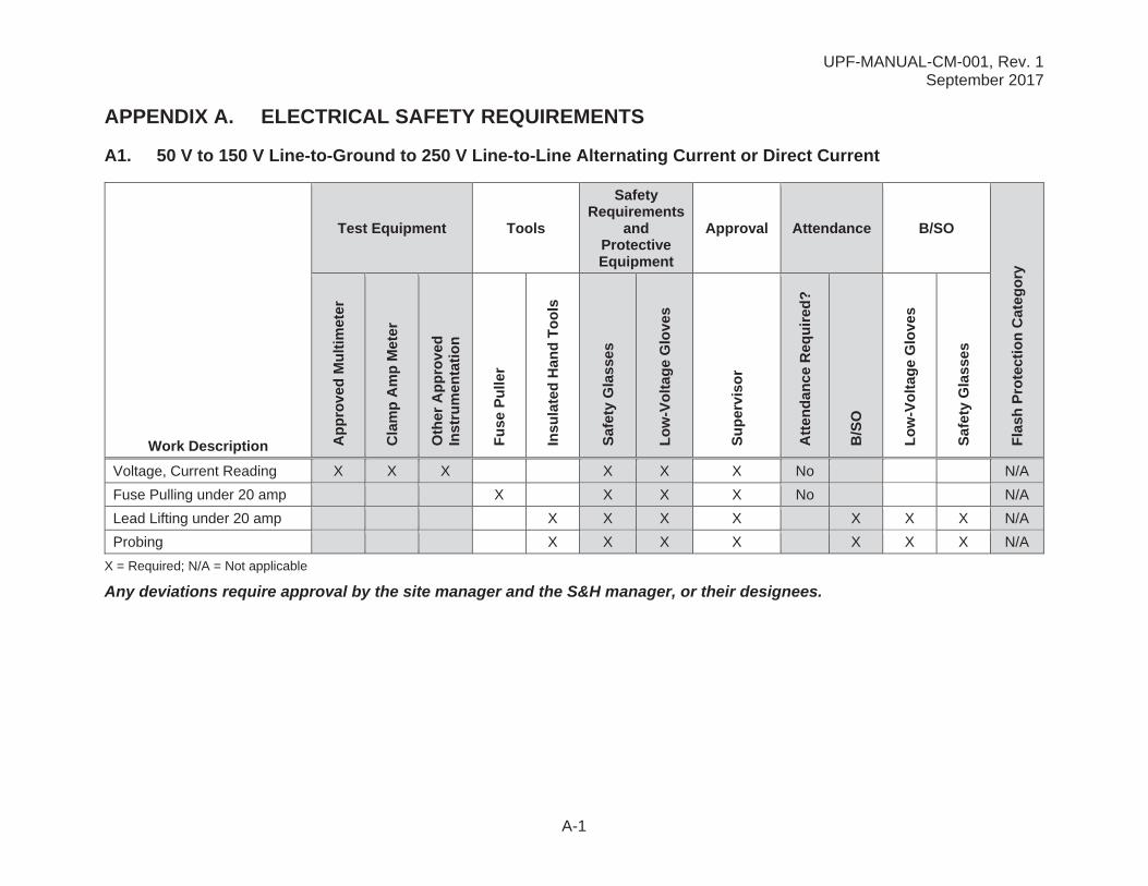
APPENDIX A. ELECTRICAL SAFETY REQUIREMENTS
A1. 50 V to 150 V Line-to-Ground to 250 V Line-to-Line Alternating Current or Direct Current
Test Equipment Tools
Safety Requirements
and Protective Equipment
Approval Attendance B/SO
Flas
h Pr
otec
tion
Cat
egor
y
Work Description App
rove
d M
ultim
eter
Cla
mp
Am
p M
eter
Oth
er A
ppro
ved
Inst
rum
enta
tion
Fuse
Pul
ler
Insu
late
d H
and
Tool
s
Safe
ty G
lass
es
Low
-Vol
tage
Glo
ves
Supe
rvis
or
Atte
ndan
ce R
equi
red?
B/S
O
Low
-Vol
tage
Glo
ves
Safe
ty G
lass
es
Voltage, Current Reading X X X X X X No N/A
Fuse Pulling under 20 amp X X X X No N/A
Lead Lifting under 20 amp X X X X X X X N/A
Probing X X X X X X X N/A
X = Required; N/A = Not applicable
Any deviations require approval by the site manager and the S&H manager, or their designees.
UPF-MANUAL-CM-001, Rev. 1September 2017
A-2
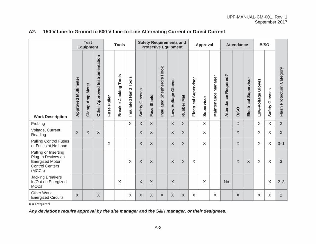
A2. 150 V Line-to-Ground to 600 V Line-to-Line Alternating Current or Direct Current
Test Equipment Tools Safety Requirements and
Protective Equipment Approval Attendance B/SO
Flas
h Pr
otec
tion
Cat
egor
y
Work Description App
rove
d M
ultim
eter
Cla
mp
Am
p M
eter
Oth
er A
ppro
ved
Inst
rum
enta
tion
Fuse
Pul
ler
Bre
aker
Jac
king
Tool
s
Insu
late
d H
and
Tool
s
Safe
ty G
lass
es
Face
Shi
eld
Insu
late
d Sh
ephe
rd’s
Hoo
k
Low
-Vol
tage
Glo
ves
Rub
ber M
at
Elec
tric
al S
uper
viso
r
Supe
rvis
or
Mai
nten
ance
Man
ager
Atte
ndan
ce R
equi
red?
B/S
O
Elec
tric
al S
uper
viso
r
Low
-Vol
tage
Glo
ves
Safe
ty G
lass
es
Probing X X X X X X X X X 2
Voltage, Current Reading
X X X X X X X X X X X 2
Pulling Control Fuses or Fuses at No Load
X X X X X X X X X 0–1
Pulling or Inserting Plug-In Devices on Energized Motor Control Centers (MCCs)
X X X X X X X X X X 3
Jacking Breakers In/Out on Energized MCCs
X X X X X No X 2–3
Other Work, Energized Circuits
X X X X X X X X X X X X X 2
X = Required
Any deviations require approval by the site manager and the S&H manager, or their designees.
UPF-MANUAL-CM-001, Rev. 1September 2017
A-3
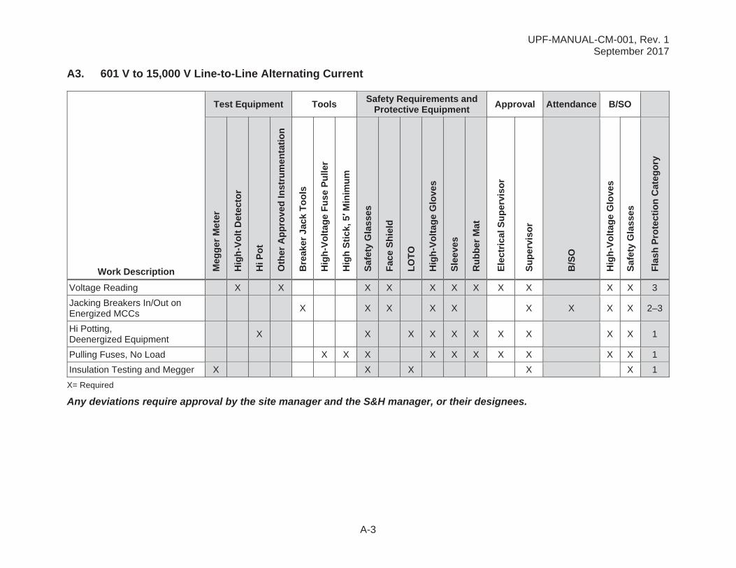
A3. 601 V to 15,000 V Line-to-Line Alternating Current
Test Equipment Tools Safety Requirements and Protective Equipment Approval Attendance B/SO
Work Description Meg
ger M
eter
Hig
h-Vo
lt D
etec
tor
Hi P
ot
Oth
er A
ppro
ved
Inst
rum
enta
tion
Bre
aker
Jac
k To
ols
Hig
h-Vo
ltage
Fus
e Pu
ller
Hig
h St
ick,
5M
inim
um
Safe
ty G
lass
es
Face
Shi
eld
LOTO
Hig
h-Vo
ltage
Glo
ves
Slee
ves
Rub
ber M
at
Elec
tric
al S
uper
viso
r
Supe
rvis
or
B/S
O
Hig
h-Vo
ltage
Glo
ves
Safe
ty G
lass
es
Flas
h Pr
otec
tion
Cat
egor
y
Voltage Reading X X X X X X X X X X X 3
Jacking Breakers In/Out on Energized MCCs
X X X X X X X X X 2–3
Hi Potting, Deenergized Equipment
X X X X X X X X X X 1
Pulling Fuses, No Load X X X X X X X X X X 1
Insulation Testing and Megger X X X X X 1
X= Required
Any deviations require approval by the site manager and the S&H manager, or their designees.
UPF-MANUAL-CM-001, Rev. 1September 2017
A-4
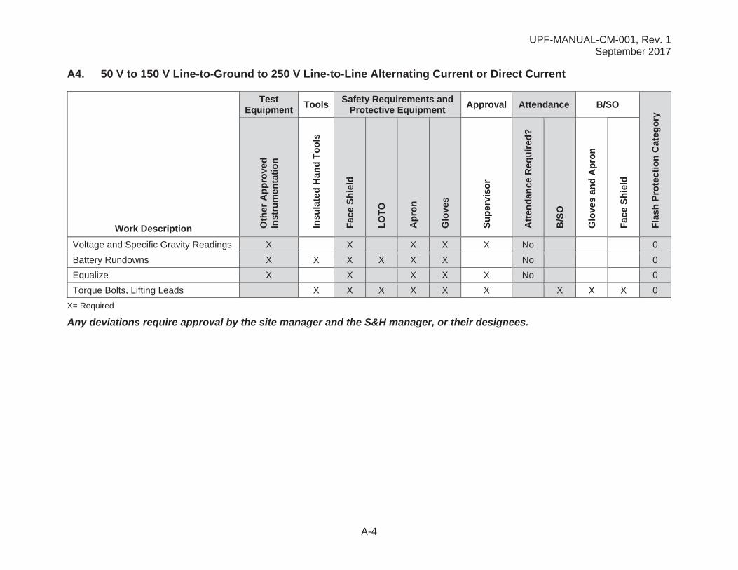
A4. 50 V to 150 V Line-to-Ground to 250 V Line-to-Line Alternating Current or Direct Current
Test Equipment Tools Safety Requirements and
Protective Equipment Approval Attendance B/SO
Flas
h Pr
otec
tion
Cat
egor
y
Work Description Oth
er A
ppro
ved
Inst
rum
enta
tion
Insu
late
d H
and
Tool
s
Face
Shi
eld
LOTO
Apr
on
Glo
ves
Supe
rvis
or
Atte
ndan
ce R
equi
red?
B/S
O
Glo
ves
and
Apr
on
Face
Shi
eld
Voltage and Specific Gravity Readings X X X X X No 0
Battery Rundowns X X X X X X No 0
Equalize X X X X X No 0
Torque Bolts, Lifting Leads X X X X X X X X X 0
X= Required
Any deviations require approval by the site manager and the S&H manager, or their designees.
UPF-MANUAL-CM-001, Rev. 1September 2017
B-1
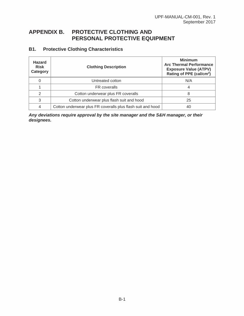
APPENDIX B. PROTECTIVE CLOTHING AND PERSONAL PROTECTIVE EQUIPMENT
B1. Protective Clothing Characteristics
Hazard Risk
CategoryClothing Description
Minimum Arc Thermal Performance Exposure Value (ATPV) Rating of PPE (cal/cm2)
0 Untreated cotton N/A
1 FR coveralls 4
2 Cotton underwear plus FR coveralls 8
3 Cotton underwear plus flash suit and hood 25
4 Cotton underwear plus FR coveralls plus flash suit and hood 40
Any deviations require approval by the site manager and the S&H manager, or their designees.
UPF-MANUAL-CM-001, Rev. 1September 2017
B-2
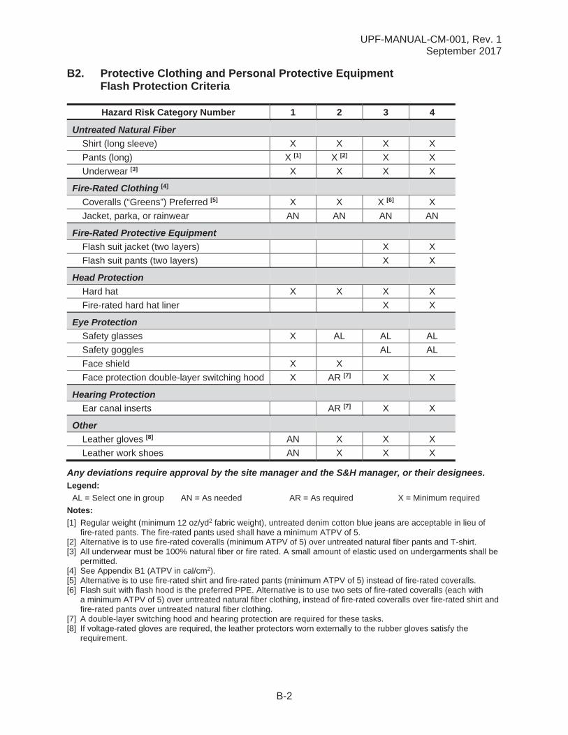
B2. Protective Clothing and Personal Protective Equipment Flash Protection Criteria
Hazard Risk Category Number 1 2 3 4
Untreated Natural FiberShirt (long sleeve) X X X X
Pants (long) X [1] X [2] X X
Underwear [3] X X X X
Fire-Rated Clothing [4]
Coveralls (“Greens”) Preferred [5] X X X [6] X
Jacket, parka, or rainwear AN AN AN AN
Fire-Rated Protective EquipmentFlash suit jacket (two layers) X X
Flash suit pants (two layers) X X
Head ProtectionHard hat X X X X
Fire-rated hard hat liner X X
Eye ProtectionSafety glasses X AL AL AL
Safety goggles AL AL
Face shield X X
Face protection double-layer switching hood X AR [7] X X
Hearing ProtectionEar canal inserts AR [7] X X
Other Leather gloves [8] AN X X X
Leather work shoes AN X X X
Any deviations require approval by the site manager and the S&H manager, or their designees.Legend:
AL = Select one in group AN = As needed AR = As required X = Minimum required
Notes:[1] Regular weight (minimum 12 oz/yd2 fabric weight), untreated denim cotton blue jeans are acceptable in lieu of
fire-rated pants. The fire-rated pants used shall have a minimum ATPV of 5.[2] Alternative is to use fire-rated coveralls (minimum ATPV of 5) over untreated natural fiber pants and T-shirt.[3] All underwear must be 100% natural fiber or fire rated. A small amount of elastic used on undergarments shall be
permitted.[4] See Appendix B1 (ATPV in cal/cm2).[5] Alternative is to use fire-rated shirt and fire-rated pants (minimum ATPV of 5) instead of fire-rated coveralls.[6] Flash suit with flash hood is the preferred PPE. Alternative is to use two sets of fire-rated coveralls (each with
a minimum ATPV of 5) over untreated natural fiber clothing, instead of fire-rated coveralls over fire-rated shirt and fire-rated pants over untreated natural fiber clothing.
[7] A double-layer switching hood and hearing protection are required for these tasks.[8] If voltage-rated gloves are required, the leather protectors worn externally to the rubber gloves satisfy the
requirement.
UPF-MANUAL-CM-001, Rev. 1September 2017
C-1
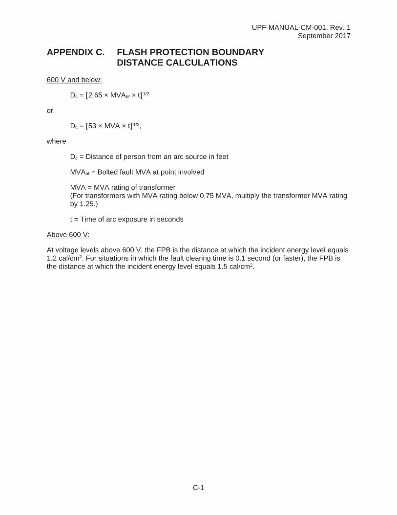
APPENDIX C. FLASH PROTECTION BOUNDARY DISTANCE CALCULATIONS
600 V and below:
Dc = [2.65 × MVAbf × t]1/2
or
Dc = [53 × MVA × t]1/2,
where
Dc = Distance of person from an arc source in feet
MVAbf = Bolted fault MVA at point involved
MVA = MVA rating of transformer (For transformers with MVA rating below 0.75 MVA, multiply the transformer MVA rating by 1.25.)
t = Time of arc exposure in seconds
Above 600 V:
At voltage levels above 600 V, the FPB is the distance at which the incident energy level equals 1.2 cal/cm2. For situations in which the fault clearing time is 0.1 second (or faster), the FPB is the distance at which the incident energy level equals 1.5 cal/cm2.

UPF-MANUAL-CM-001, Rev. 1September 2017
D-1
APPENDIX D. ENERGIZED ELECTRICAL WORK PERMIT
The controlled version of this template (CFN-1194) can be found in Just-In-Time (JIT) forms..
Initials: __________
Date: 02/14/18
1232
UPF-MANUAL-CM-001, Rev. 1September 2017
E-1
APPENDIX E. ENERGIZED ELECTRICAL WORK PERMITINSTRUCTIONS
The log for Energized Electrical Work Permit (EEWP) forms shall be maintained by the system engineer or designee.
A. EEWP Preparation
1) The EEWP requestor (either the system engineer or subcontractor representative) shall fill out section 1 of the EEWP.
2) The EEWP requestor shall identify the employees to perform the planned work and ensure they are qualified to perform the work on or near exposed live parts (qualified electrical persons).
3) The EEWP requestor shall sign the permit and obtain the appropriate signatures and then forward the form to the system engineer (or designated individual) for logging.
B. The system engineer shall ensure the EEWP was logged and shall review the EEWP to determine whether the EEWP contains a justification that meets the criteria. If so, and if no other issues to the contrary exist, the field engineer signs section 1 of the EEWP and then completes section 2 of the EEWP.
C. The system engineer enters the permit effective date range. No work authorized by the EEWP shall be performed outside of the permit effective date range.
D. The department manager and the S&H representative, or their designees as appropriate, review the EEWP and sign section 3 to authorize the planned work.
E. Once the EEWP is authorized to perform the work, the system engineer conducts a pre-job brief. The field engineer notifies the person in charge of the work area and work operation covered by the EEWP. The required STARRT cards and/or JHAs shallbe developed and/or reviewed by the assigned employees.
F. Section 4 of the EEWP shall be completed by the system engineer as a supplement to the STARRT card when applicable. The field engineer retains the original EEWP until the permit is closed, and the EEWP is kept with the applicable STARRT card at the work location for the duration of the work activity.
G. Closed EEWPs shall be returned to the system engineer, or designee, for proper filing and logging.
UPF-MANUAL-CM-001, Rev. 1September 2017
F-1
APPENDIX F. UPF OWNER’S INSPECTOR DELEGATE APPROVALFORM
Use this form to obtain AJH approval for UPF Owner’s Inspector Delegate (OID).
The UPF Project is submitting _________________as an Electrical Owners Inspector Delegate Candidate based on the following requirements of Y73-528, Qualifications of the Owner’s Electrical Inspector.
Have a minimum of 5 years combined schooling/experience with electrical/electronic system design and/or electrical system construction/installation/inspection.
Has completed the current NFPA 70 National Electric Code refresher training every three years.
Has completed the International Code Council (ICC) certification for Commercial Electrical Inspector or International Association of Electrical Inspectors (IAEI).
Approved by:
_____________________________________________________________Mark Gibbs DateCNS Electrical Authority Having Jurisdiction
Related Documents