Upstream Channel Bonding The Upstream Channel Bonding (USCB) feature helps cable operators offer higher upstream (US) bandwidth per cable modem (CM) user by combining multiple radio frequency (RF) channels to form a larger bonding group at the MAC layer. Finding Feature Information Your software release may not support all the features documented in this module. For the latest feature information and caveats, see the release notes for your platform and software release. To find information about the features documented in this module, and to see a list of the releases in which each feature is supported, see the Feature Information Table at the end of this document. Use Cisco Feature Navigator to find information about platform support and Cisco software image support. To access Cisco Feature Navigator, go to http://tools.cisco.com/ITDIT/CFN/. An account on http:// www.cisco.com/ is not required. Contents • Hardware Compatibility Matrix for Cisco cBR Series Routers, page 2 • Prerequisites for Upstream Channel Bonding , page 2 • Restrictions for Upstream Channel Bonding , page 3 • Information About Upstream Channel Bonding, page 3 • How to Configure Upstream Channel Bonding , page 13 • Configuration Example for Upstream Channel Bonding , page 30 • Verifying the Upstream Channel Bonding Configuration, page 31 • Additional References, page 32 • Feature Information for Upstream Channel Bonding , page 33 Cisco Converged Broadband Routers Software Configuration Guide For DOCSIS 1

Welcome message from author
This document is posted to help you gain knowledge. Please leave a comment to let me know what you think about it! Share it to your friends and learn new things together.
Transcript

Upstream Channel Bonding
The UpstreamChannel Bonding (USCB) feature helps cable operators offer higher upstream (US) bandwidthper cable modem (CM) user by combining multiple radio frequency (RF) channels to form a larger bondinggroup at the MAC layer.
Finding Feature Information
Your software release may not support all the features documented in this module. For the latest featureinformation and caveats, see the release notes for your platform and software release. To find informationabout the features documented in this module, and to see a list of the releases in which each feature issupported, see the Feature Information Table at the end of this document.
Use Cisco Feature Navigator to find information about platform support and Cisco software image support.To access Cisco Feature Navigator, go to http://tools.cisco.com/ITDIT/CFN/. An account on http://www.cisco.com/ is not required.
Contents
• Hardware Compatibility Matrix for Cisco cBR Series Routers, page 2
• Prerequisites for Upstream Channel Bonding , page 2
• Restrictions for Upstream Channel Bonding , page 3
• Information About Upstream Channel Bonding, page 3
• How to Configure Upstream Channel Bonding , page 13
• Configuration Example for Upstream Channel Bonding , page 30
• Verifying the Upstream Channel Bonding Configuration, page 31
• Additional References, page 32
• Feature Information for Upstream Channel Bonding , page 33
Cisco Converged Broadband Routers Software Configuration Guide For DOCSIS 1

Hardware Compatibility Matrix for Cisco cBR Series Routers
The hardware components introduced in a given Cisco IOS-XE Release are supported in all subsequentreleases unless otherwise specified.
Note
Table 1: Hardware Compatibility Matrix for the Cisco cBR Series Routers
Interface CardsProcessor EngineCisco CMTS Platform
Cisco IOS-XE Release 3.15.0Sand Later Releases
Cisco cBR-8 CCAP Line Cards:
• PID—CBR-LC-8D30-16U30
• PID—CBR-LC-8D31-16U30
• PID—CBR-RF-PIC
• PID—CBR-RF-PROT-PIC
Cisco cBR-8 Downstream PHYModules:
• PID—CBR-D30-DS-MOD
• PID—CBR-D31-DS-MOD
Cisco cBR-8 Upstream PHYModules:
• PID—CBR-D30-US-MOD
Cisco IOS-XE Release 3.15.0Sand Later Releases
Cisco cBR-8 Supervisor:
• PID—CBR-CCAP-SUP-160G
• PID—CBR-CCAP-SUP-60G1
• PID—CBR-SUP-8X10G-PIC
Cisco cBR-8 ConvergedBroadband Router
1 Effective with Cisco IOS-XE Release 3.17.0S, CBR-CCAP-SUP-60G supports 8 cable line cards. The total traffic rate is limited to 60Gbps, the total numberof downstream service flow is limited to 72268, and downstream unicast low-latency flow does not count against the limits.
Prerequisites for Upstream Channel Bonding• Enable downstream channel bonding before configuring the Upstream Channel Bonding feature on aCisco cable modem termination system (CMTS) router.
• Ensure that the CM is registered inMultiple Receive Channel (MRC)mode before configuring upstreamchannel bonding on a Cisco CMTS router.
• Ensure that the CM is DOCSIS 3.0 certified.
Cisco Converged Broadband Routers Software Configuration Guide For DOCSIS2
Upstream Channel BondingHardware Compatibility Matrix for Cisco cBR Series Routers

Restrictions for Upstream Channel BondingThe following are the general restrictions for the Upstream Channel Bonding feature:
• Only the static bonding groups are supported.
• Only the upstream channels belonging to the same MAC domain can be added to an upstream bondinggroup.
Starting from Cisco IOS-XE 3.18.0S release, maximum of 16 upstream channels canbe configured for each MAC Domain, which are divided into two groups:
Note
• Group 1: upstream channel 0-7
• Group 2: upstream channel 8-15
The upstream bonding-group should include all the upstream channels either fromGroup 1 or Group 2 only.
• Committed information rate (CIR) oversubscription is not supported on USCB groups.
Cisco CMTS allows oversubscription of the available bandwidth for individual upstream channels.However, oversubscription of bandwidth is not supported for USCB groups.
An individual upstreammay get oversubscribed due to static CIR service flows created for voice traffic.This may cause the DOCSIS 3.0 CMs with USCB to come online on single channel US bonding group(also known as default bonding group).
This problem is mainly encountered in the voice deployments using static service flows. It is, therefore,recommended to choose from the following voice deployments such that the CIR is allocated (or released)when a voice call is attempted (or dropped):
1 Dynamic Quality of Service (DQoS) Lite2 Packet Cable (PC) DQoS3 Packet Cable Multimedia (PCMM)
These deployments avoid the individual upstream oversubscription and CMs come online on expectedbonding groups.
Information About Upstream Channel BondingDOCSIS 3.0-based upstream channel bonding is a method for increasing upstream bandwidth up to amaximumof 120 Mbps raw throughput per CM user in a cable communications system that includes a Cisco CMTSrouter and multiple CMs. The upstream channel bonding method enables a CM to transmit data to a CiscoCMTS router on multiple upstream channels simultaneously.
Channel bonding is a method by which smaller bandwidth upstream channels are bonded together to createa larger upstream bonding group in the MAC domain. A MAC domain is a logical sub-component of a CiscoCMTS router and is responsible for implementing all DOCSIS functions on a set of downstream and upstreamchannels.
Cisco Converged Broadband Routers Software Configuration Guide For DOCSIS 3
Upstream Channel BondingRestrictions for Upstream Channel Bonding

The Upstream Channel Bonding feature supports upstream traffic in Multiple Transmit Channel (MTC) modefor data and video services as these services require more bandwidth than voice-based services. Voice-basedservices either use the traditional single upstream channel or a single upstream channel bonding groupconfiguration. Any traffic contract that exceeds 30 Mbps requires upstream channel bonding as the physicalcapacity of a single RF channel in DOCSIS cannot exceed 30 Mbps.
The Upstream Channel Bonding feature is supported on the Cisco cBR-8 router. Upstream data from thesubscriber comes through the upstream ports (US0-US19) that are automatically configured on the cableinterface line card. The cable interface line card processes the data and sends it across the backplane to theWAN card and out to the Internet.
The table below lists the downstream and upstream frequency supported on the cable interface line card.
Table 2: Downstream and Upstream Frequency
Upstream FrequencyDownstream FrequencyLine Card
The upstream frequency range forthe Cisco cBR-8 CCAP line cardis from 5 to 85 MHz irrespectiveof the region and Annexureconfiguration.
55-999 MHz2Cisco cBR-8 CCAP
2 This frequency range is subjected to the frequency restriction of the attached EQAM device.
Multiple Transmit Channel ModeMultiple Transmit Channel mode is a CM capability that enables CMs to send upstream traffic on multipleupstream channels. You can enable the MTC mode on a cable interface line card:
• MTC mode for all CMs in a MAC domain—The MTC mode for all CMs in a MAC domain is enabledby default on an upstream bonding capable cable interface line card.
Multiple Receive Channel ModeMRC mode is a CM capability that enables CMs to receive downstream traffic on multiple downstreamchannels. The MRC mode is enabled by default on an upstream bonding capable cable interface line card.You can enable or disable the MRC mode in the MAC domain during or after the CM registration using thecable mrc-mode command.
Dynamic Range Window and Transmit Power Levels for Upstream ChannelBonding
The dynamic range window functionality is based on the CableLabs DOCSIS 3.0 MAC and Upper LayerProtocols Interface Specification and DOCSIS 3.0 Specification. This requires a DOCSIS 3.0 CM to haveupstream transmit channel power level within a 12 dB range for all channels in its transmit channel set (TCS).
Cisco Converged Broadband Routers Software Configuration Guide For DOCSIS4
Upstream Channel BondingMultiple Transmit Channel Mode

DOCSIS 1.x or 2.0 CMs operating with a single upstream channel, in non-MTCmode, have a higher maximumtransmit power level than DOCSIS 3.0 CMs operating in theMTCmode with two or more upstream channels.That is, the maximum transmit power level per channel is reduced in the MTC mode.
When the upstream attenuation exceeds the maximum transmit power level, a DOCSIS 3.0 CM attemptingto register in the MTC mode may fail to come online, or register in partial mode. The CM fails to registerwhen the transmit power level of all upstream channels in its TCS exceeds the maximum transmit power level.If the CM has some upstream channels that are within the maximum transmit power level, the CMmay comeonline in partial mode. However, the upstream channels that exceed the maximum transmit power level aremarked as down and cannot be used for upstream traffic.
To verify the transmit power levels on a CM, use the show cable modem command with the verbose keyword.This command displays the following transmit power values for each assigned upstream channel:
• Reported Transmit Power—This is the reported transmit power level by the CM for each upstreamchannel.
• Minimum Transmit Power—This is the minimum transmit power level that the CM in the MTC modecould transmit at for the upstream channel.
• Peak Transmit Power—This is the maximum transmit power level that the CM in the MTC mode couldtransmit at for the upstream channel.
To support upstream channel bonding, the minimum transmit power must be less than or equal to the reportedtransmit power, and the reported transmit power must be less than or equal to the peak transmit power. Thepeak transmit power and minimum transmit power levels are derived from the CM TCS assignment and eachindividual upstream channel configuration.
If the minimum transmit power is higher than the reported transmit power, or the reported transmit power ishigher than the peak transmit power, the CM may not come online or may register in partial mode.
You can troubleshoot this transmit power problem in the following two ways:
• Insert an additional amplifier to reduce the upstream attenuation so that the upstream transmit powerfalls within the allowed transmit power range (12 dB).
• Disable theMTCmode. To switch the CM from theMTCmode to non-MTCmode, disable the bonded-bit(bit-0) in type, length, value (TLV) 43.9.3 using the CM configuration file.
Extended Transmit PowerDuring the early deployment of DOCSIS 3.0 CMs, additional power is required from the CMs in order tocompensate for the attenuation in the upstream path. CMs should transmit at extended power level than thatdefined in DOCSIS. This scenario is generally observed when USCB is enabled at the Cisco CMTS and theDOCSIS 3.0 CMs are operating in MTC mode.
Additional upstream power provides the operator with a power margin that helps overcome the upstreamsignal loss, reduces the cable plant operational cost, and enables rapid deployment of DOCSIS 3.0 CMs.
The Cisco CMTS supports the following features with which the CMs can transmit data at an extended power:
• Cisco Extended Transmit Power Feature
• DOCSIS Extended Transmit Power Feature
Cisco Converged Broadband Routers Software Configuration Guide For DOCSIS 5
Upstream Channel BondingDynamic Range Window and Transmit Power Levels for Upstream Channel Bonding

Cisco Extended Transmit Power Feature
The Cisco Extended Transmit Power feature supports DOCSIS 3.0 CMs operating in MTC mode to transmitat a higher power level than the power level specified in theDOCSIS 3.0 Specification. This feature is supportedonly with Cisco DPC3000 CMs.
The Cisco Extended Transmit Power feature enables cable operators to have better control on the cable modemsthat register in 4-channel or 2-channel MTC mode or in non-MTC mode to transmit at a higher power levelthan the DOCSIS-defined maximum power level. The cable operator can configure extended transmit powerusing the cable tx-power-headroom command in global configuration mode.
DOCSIS Extended Transmit Power Feature
The DOCSIS Extended Transmit Power feature supports extended upstream transmit power capability asdefined in the DOCSIS3.0 Specification. This feature allows the CMs to transmit at a high extended powerlevel to counter the attenuation in the US channel.
The table below lists the new TLVs supported by the DOCSIS Extended Transmit Power feature.
Table 3: TLVs for DOCSIS Extended Power Feature
ValueLengthTypeTLV Name
0—Extended UpstreamTransmit Power SupportOff
1—Extended UpstreamTransmit Power SupportOn
2-255—Reserved
116Extended UpstreamTransmit Power Support
0, 205-244 (units ofone-quarter dB)
15.40Extended UpstreamTransmit Power CMCapability
The Cisco CMTS sends TLV16 to inform the CM if the DOCSIS Extended Transmit Power feature is enabled.The CM in turn, sends TLV5.40 to the Cisco CMTS to communicate its extended power capability. After thenegotiations are complete, the CM can transmit at an extended power.
DOCSIS Extended Transmit Power feature is enabled by default. Use the cable upstream ext-power commandto enable or disable this feature. For more information on how to enable or disable DOCSIS Extended Powerfeature, see Configuring DOCSIS Extended Transmit Power Feature, on page 28.
DOCSIS Extended Transmit Power feature takes precedence, if both Cisco Extended Transmit Powerfeature and DOCSIS Extended Transmit Power feature are configured.
Note
Cisco Converged Broadband Routers Software Configuration Guide For DOCSIS6
Upstream Channel BondingDynamic Range Window and Transmit Power Levels for Upstream Channel Bonding

Reduced Transmit Channel SetThe Reduced Transmit Channel Set feature enables the Cisco CMTS router to reduce upstream channel setassignment based on the total power budget of the CM. For example, a reduction from four to two upstreamchannels gains 3 dB headroom. Further reduction from two channels to a single channel gains another 3 dBheadroom, and the CM starts operating in non-MTC mode.
In order to take advantage of the reduced upstream channel set, the corresponding static bonding groups mustbe configured. For example, a MAC domain is configured with a bonding group having four channels. A CMwith the reduced channel set of two is unable to match to the 4-channel bonding group, and can only bematched to a bonding group with two channels or less.
The Reduced Transmit Channel Set feature is helpful when a DOCSIS 3.0 CM is required to increase its totaltransmit power by 3 dB. For example, a DOCSIS 1.0 or 2.0 CM supports a maximum transmit power of 58dBmV for Quadrature Phase Shift Keying (QPSK)modulation, while a DOCSIS 3.0 CM supports a maximumtransmit power of 61 dBmV. In this case, the DOCSIS 3.0 CM operating in 4-channel MTC mode has areduction in the maximum transmit power per upstream channel. This feature enables the Cisco CMTS routerto support reduced input power level by 6 dB to prevent upstream path attenuation.
T4 MultiplierT4multiplier is the T4 timeout multiplier value of the default T4 timeout values as defined in for cable modemsthat are in the MTC mode. The default value is derived from the number of channels in the modem transmitchannel set. You can change the default T4 multiplier value using the cable upstream ranging-poll commandin cable interface configuration mode.
The T4 timeout multiplier values range is from 1 to 10. If the T4 multiplier value is equal to 1, the cablemodem will T4 time out in 30 seconds (that is, 1 x 30 = 30). If you change the T4 multiplier to 4, then thenew T4 timeout value will be 120 seconds (that is, 4 x 30 = 120).
If the T4 timeout multiplier is not configured from the range (1 - 10), then the CMTS uses the T4 timeoutvalue of modem as T4 timeout value. For example, if the T4 timeout of the modem is 90 seconds, thenthe CMTS applies 3 as the T4 multiplier.
Note
In the MTC mode, you can increase the T4 timeout value in order to reduce the router overhead associatedwith processing of ranging request (RNG-REQ) slots and ranging response messages. If an RNG-RSPmessagedoes not contain a T4 timeout multiplier value, then the CM uses the default T4 timeout value.
Fiber Node Configuration for Upstream Channel BondingThe fiber node configuration on a Cisco CMTS router is used to define MAC domain downstream servicegroups (MD-DS-SGs) and MAC domain upstream service groups (MD-US-SGs) as defined in DOCSIS 3.0.Only the DOCSIS 3.0 certified modems use this information.
In hybrid fiber coaxial (HFC) networks, all CMs connected to the same coaxial segment of a fiber node reachthe same set of downstream and upstream channels on one or more Cisco CMTS routers located at the headend.
A CM is physically connected to only one fiber node. The fiber node must include at least one primary-capablecontroller for the CM connected to the fiber node to be operational.
Cisco Converged Broadband Routers Software Configuration Guide For DOCSIS 7
Upstream Channel BondingT4 Multiplier
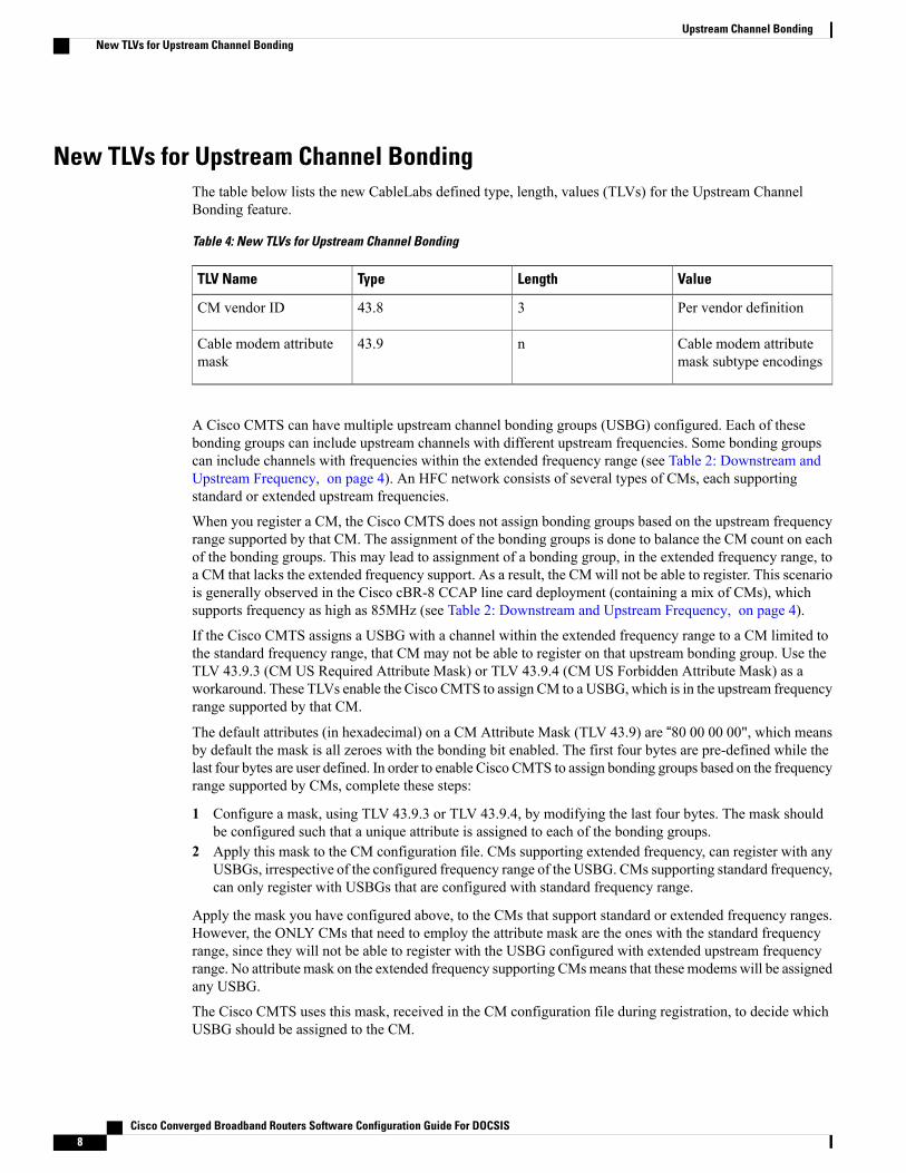
New TLVs for Upstream Channel BondingThe table below lists the new CableLabs defined type, length, values (TLVs) for the Upstream ChannelBonding feature.
Table 4: New TLVs for Upstream Channel Bonding
ValueLengthTypeTLV Name
Per vendor definition343.8CM vendor ID
Cable modem attributemask subtype encodings
n43.9Cable modem attributemask
A Cisco CMTS can have multiple upstream channel bonding groups (USBG) configured. Each of thesebonding groups can include upstream channels with different upstream frequencies. Some bonding groupscan include channels with frequencies within the extended frequency range (see Table 2: Downstream andUpstream Frequency, on page 4). An HFC network consists of several types of CMs, each supportingstandard or extended upstream frequencies.
When you register a CM, the Cisco CMTS does not assign bonding groups based on the upstream frequencyrange supported by that CM. The assignment of the bonding groups is done to balance the CM count on eachof the bonding groups. This may lead to assignment of a bonding group, in the extended frequency range, toa CM that lacks the extended frequency support. As a result, the CMwill not be able to register. This scenariois generally observed in the Cisco cBR-8 CCAP line card deployment (containing a mix of CMs), whichsupports frequency as high as 85MHz (see Table 2: Downstream and Upstream Frequency, on page 4).
If the Cisco CMTS assigns a USBG with a channel within the extended frequency range to a CM limited tothe standard frequency range, that CM may not be able to register on that upstream bonding group. Use theTLV 43.9.3 (CM US Required Attribute Mask) or TLV 43.9.4 (CM US Forbidden Attribute Mask) as aworkaround. These TLVs enable the Cisco CMTS to assign CM to a USBG, which is in the upstream frequencyrange supported by that CM.
The default attributes (in hexadecimal) on a CM Attribute Mask (TLV 43.9) are “80 00 00 00", which meansby default the mask is all zeroes with the bonding bit enabled. The first four bytes are pre-defined while thelast four bytes are user defined. In order to enable Cisco CMTS to assign bonding groups based on the frequencyrange supported by CMs, complete these steps:
1 Configure a mask, using TLV 43.9.3 or TLV 43.9.4, by modifying the last four bytes. The mask shouldbe configured such that a unique attribute is assigned to each of the bonding groups.
2 Apply this mask to the CM configuration file. CMs supporting extended frequency, can register with anyUSBGs, irrespective of the configured frequency range of the USBG. CMs supporting standard frequency,can only register with USBGs that are configured with standard frequency range.
Apply the mask you have configured above, to the CMs that support standard or extended frequency ranges.However, the ONLY CMs that need to employ the attribute mask are the ones with the standard frequencyrange, since they will not be able to register with the USBG configured with extended upstream frequencyrange. No attribute mask on the extended frequency supporting CMsmeans that these modems will be assignedany USBG.
The Cisco CMTS uses this mask, received in the CM configuration file during registration, to decide whichUSBG should be assigned to the CM.
Cisco Converged Broadband Routers Software Configuration Guide For DOCSIS8
Upstream Channel BondingNew TLVs for Upstream Channel Bonding

Upstream Weighted Fair QueuingThe upstreamweighted fair queuing (WFQ) is a quality of service (QoS) feature that enables the Cisco CMTSrouter to allocate optimum bandwidth to upstream service flows based on theWFQ parameter configurations.To enable upstream WFQ, you must configure either the class-based or activity-based WFQ on a cableinterface.
The following WFQ parameter configurations are supported:
Class-Based Weighted Fair QueuingIn the class-based weighted fair queuing configuration, allocation of available bandwidth is dependent on theservice flows that are active in a service class. A service class is a group of queuing attributes configured onthe Cisco CMTS router. The class must have at least one active service flow. The class receives its portionof the available bandwidth based on the weight of the class. By default, each class (0 to 7) has a weight of“class + 1.” For example, the class 0 has a weight of 1, and class 1 has a weight of 2.
Activity-Based Weighted Fair QueuingIn the activity-based weighted fair queuing configuration, allocation of available bandwidth is based on theservice class and the total number of service flows that are active in a map for the service class. A serviceclass with higher number of service flows receives the larger percentage of bandwidth.
Custom Weight for Service Flow PrioritiesThe weighted fair queuing functionality helps the Cisco CMTS router share the available bandwidth basedon the weight of the service flow priorities specified for outstanding requests from an upstream service flow.Priority refers to the service flow priority specified in the CM configuration file, or the Cisco CMTS serviceclass configuration. By default, the weight of a priority is equal to “priority+1.” For example, priority 0 has aweight of 1, and priority 1 has a weight of 2. A higher priority provides more weight to the outstanding request.The custom weight can be specified for a total of eight priorities (0 to 7) in a service class.
The priority parameter refers to the priority of traffic in a service flow ranging from 0 (the lowest) to 7 (thehighest). In the upstream traffic, all of the pending high priority service flows are scheduled for transmissionbefore low priority service flows. You can configure the weight for priorities based on how much weight isappropriate per priority.
The table below lists the default weight for each service flow priority.
Table 5: Default Weight of Service Flow Priorities
Default WeightService Flow Priority
10
21
32
43
Cisco Converged Broadband Routers Software Configuration Guide For DOCSIS 9
Upstream Channel BondingUpstream Weighted Fair Queuing

Default WeightService Flow Priority
54
65
76
87
Upstream Scheduler and Service FlowsA DOCSIS-qualified Cisco CMTS router can provide varied upstream scheduling modes for different packetstreams or applications using upstream service flows. A service flow represents either an upstream or adownstream flow of data. A unique service flow ID (SFID) identifies each service flow. Each service flowcan have its own quality of service (QoS) parameters, such as maximum throughput, minimum guaranteedthroughput, and priority. In the case of upstream service flows, you can also specify a scheduling mode.
Scheduling is a process that enables the Cisco CMTS router to receive bandwidth requests and grant timeslotsto CMs for the upstream traffic. The Cisco CMTS router periodically creates a grant map for each enabledupstream channel. The map grants individual timeslots to enable CMs to place packets on the upstreamchannels.
DOCSIS 3.0 describes a method by which a CM creates an upstream service flow. The following schedulingtypes enable the Cisco CMTS router to allocate bandwidth for upstream service flows:
• Unsolicited grant service (UGS)
• Solicited grant service
The unsolicited grant service is primarily used for voice. In the case of UGS, the CM does not have to explicitlyrequest grants from the Cisco CMTS router whereas in the solicited grant service the CM has to explicitlyrequest grants from the Cisco CMTS router. The solicited grant service is primarily used for best effort (BE)services.
Unlike DOCSIS 2.0, DOCSIS 3.0 allows multiple outstanding requests per service flow. For more informationabout the upstream scheduler, see the Upstream Scheduler Mode for the Cisco CMTS Routers feature guideat the following URL:
http://www.cisco.com/en/US/docs/ios/cable/configuration/guide/cmts_upstm_sch_md_ps2209_TSD_Products_Configuration_Guide_Chapter.html
Upstream Service Flow FairnessThe service flows in the same class receive approximately the same amount of bandwidth. Fairness resolvesthe bandwidth distribution disparity among various service flows including:
• non-bonded service flow vs bonded service flows
• Service flows on modems of different vendors, i.e Intel/TI vs Broadcom
• Service flows associated with different sized bonding groups, i.e. 1,2 4 channels
Cisco Converged Broadband Routers Software Configuration Guide For DOCSIS10
Upstream Channel BondingUpstream Scheduler and Service Flows
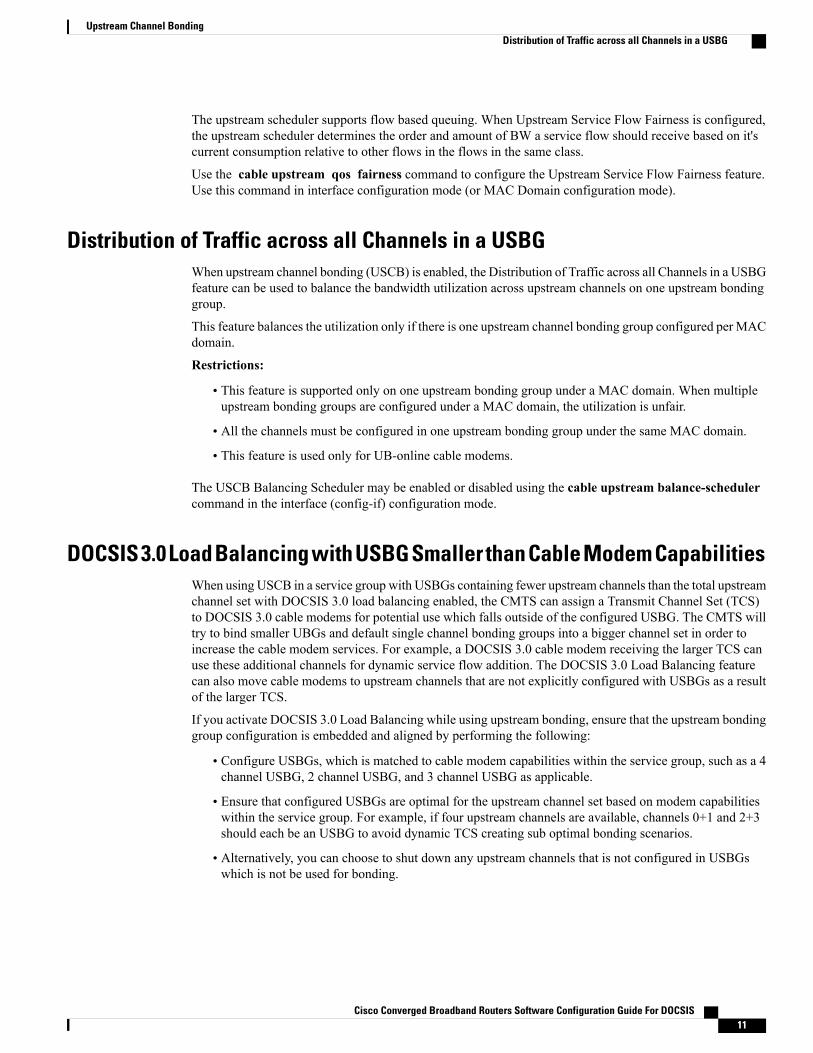
The upstream scheduler supports flow based queuing. When Upstream Service Flow Fairness is configured,the upstream scheduler determines the order and amount of BW a service flow should receive based on it'scurrent consumption relative to other flows in the flows in the same class.
Use the cable upstream qos fairness command to configure the Upstream Service Flow Fairness feature.Use this command in interface configuration mode (or MAC Domain configuration mode).
Distribution of Traffic across all Channels in a USBGWhen upstream channel bonding (USCB) is enabled, the Distribution of Traffic across all Channels in a USBGfeature can be used to balance the bandwidth utilization across upstream channels on one upstream bondinggroup.
This feature balances the utilization only if there is one upstream channel bonding group configured per MACdomain.
Restrictions:
• This feature is supported only on one upstream bonding group under a MAC domain. When multipleupstream bonding groups are configured under a MAC domain, the utilization is unfair.
• All the channels must be configured in one upstream bonding group under the same MAC domain.
• This feature is used only for UB-online cable modems.
The USCB Balancing Scheduler may be enabled or disabled using the cable upstream balance-schedulercommand in the interface (config-if) configuration mode.
DOCSIS 3.0 Load Balancing with USBG Smaller than Cable Modem CapabilitiesWhen using USCB in a service group with USBGs containing fewer upstream channels than the total upstreamchannel set with DOCSIS 3.0 load balancing enabled, the CMTS can assign a Transmit Channel Set (TCS)to DOCSIS 3.0 cable modems for potential use which falls outside of the configured USBG. The CMTS willtry to bind smaller UBGs and default single channel bonding groups into a bigger channel set in order toincrease the cable modem services. For example, a DOCSIS 3.0 cable modem receiving the larger TCS canuse these additional channels for dynamic service flow addition. The DOCSIS 3.0 Load Balancing featurecan also move cable modems to upstream channels that are not explicitly configured with USBGs as a resultof the larger TCS.
If you activate DOCSIS 3.0 Load Balancing while using upstream bonding, ensure that the upstream bondinggroup configuration is embedded and aligned by performing the following:
• Configure USBGs, which is matched to cable modem capabilities within the service group, such as a 4channel USBG, 2 channel USBG, and 3 channel USBG as applicable.
• Ensure that configured USBGs are optimal for the upstream channel set based on modem capabilitieswithin the service group. For example, if four upstream channels are available, channels 0+1 and 2+3should each be an USBG to avoid dynamic TCS creating sub optimal bonding scenarios.
• Alternatively, you can choose to shut down any upstream channels that is not configured in USBGswhich is not be used for bonding.
Cisco Converged Broadband Routers Software Configuration Guide For DOCSIS 11
Upstream Channel BondingDistribution of Traffic across all Channels in a USBG

Cisco cBR-8 CCAP Line Card Rate LimitingThe rate limiting functionality enables you control the aggregated rate and CPU consumption of upstreamtraffic for DOCSIS 3.0 bonded service flows on the Cisco cBR-8 CCAP line card. The rate limiting functionalityis configured by default on the Cisco cBR-8 CCAP line card. However, the default configuration can bemodified using the cable upstream rate-limit-ccf command.
The rate limiting functionality uses the following two rate limiting methods:
• Aggregated rate limiting—This is based on Peripheral Component Interconnect (PCI) bus aggregatedthroughput. The throughput is per line card for all bonded service flows. You can modify the defaultthroughput and burst rate configuration. The maximum allowed throughput is 115 Mbps.
• CPU-based rate limiting—This method controls the CPU consumed by Continuous Concatenation andFragmentation (CCF) and ensures that the line card functions properly when traffic is overloaded withbonded service flows. The default configuration allocates 50 per cent of CPU to CCF. You can modifythe default CPU threshold value and burst rate as required.
SID TrackingThe service ID (SID) tracking functionality enables you to track events related to upstream bandwidth requestsand processing of grants. The SID tracker module can track events for a maximum of two service flows perMAC domain. The SID tracker module tracks up to 40,000 events per service flow on a cable interface linecard.
You can enable SID tracking for the following types of events:
• DOCSIS 2.0 bandwidth request
• DOCSIS 3.0 bandwidth request
• Grant
• Pending grant (due to traffic congestion)
• Pending grant (due to shaping)
You can enable SID tracking using the track keyword along with the debug cable interface sid command.To verify SID tracking, use the show interface cable upstream debug command in privileged EXEC mode.
Service ID ClustersA Cisco CMTS router can assign one or more service ID clusters to the upstream bonded service flows(upstream service flows assigned to an upstream bonding group) at the time of service flow creation. A SIDcluster contains one SID per upstream in a bonding group. A CM uses one of the SIDs defined in the SIDcluster for the upstream interface when the CM sends a bandwidth request. The CM chooses a SID or a SIDcluster based on the SID cluster switching criteria.
For example, assume that a CM has ranged on upstream channels from 1 to 4. The Cisco CMTS router createsa bonded service flow and assigns a single SID cluster to each upstream channel. That is SID1 for UP1, SID2for UP2, SID3 for UP3, and SID4 for UP4. Now, the CM can send a bandwidth request using any of the fourupstream channels. That is, the CM can request bandwidth on any of the upstream interfaces in the SID cluster
Cisco Converged Broadband Routers Software Configuration Guide For DOCSIS12
Upstream Channel BondingCisco cBR-8 CCAP Line Card Rate Limiting

using the SID defined for the particular upstream. The Cisco CMTS router grants bandwidth to the CM usingany combination of upstream channels.
How to Configure Upstream Channel Bonding
Before configuring the Upstream Channel Bonding feature, ensure that the fiber node is configured. Thefiber node must be configured in accordance with the physical plant topology.
Note
The following tasks describe how to configure Upstream Channel Bonding on the Cisco cBR-8 router:
Enabling MTC Mode on a Cisco CMTS RouterTo section explains how to enable the MTC mode on a Cisco CMTS router.
Default MTC Mode Configuration on a Cisco CMTS RouterBy default, the MTC mode is configured on a cable interface line card. With this default configuration, theCisco CMTS router enables the MTC mode on a per MAC domain basis depending on the configuration fileof each CM. When the CM configuration file has the bonded-bit (bit-0) enabled in TLV 43.9.3 (cable modemupstream required attribute mask), the Cisco CMTS router enables the CM to come online in the MTC mode.If the CM configuration file does not have the bonded-bit on, the CM comes online in non-MTC mode.
For more information on how to add the required attribute in the CM configuration file, see Example: EnablingMTC Mode for a Single CM Using the CM Configuration File, on page 31.
Enabling MTC Mode for All CMs
This MTC mode configuration supersedes the default MTC mode configuration (per CM basis) with therequired attribute. To disable the MTC mode for all CMs in a MAC domain, use the no form of the cablemtc-mode command. If the MTC mode is enabled and the forbidden mask of the upstream bonding inTLV 43.9.4 is disabled, the CM does not support the Upstream Channel Bonding feature.
Note
Procedure
PurposeCommand or Action
Enables privileged EXEC mode.enableStep 1
Example:Router> enable
Enter your password if prompted.
Enters global configuration mode.configure terminal
Example:Router# configure terminal
Step 2
Cisco Converged Broadband Routers Software Configuration Guide For DOCSIS 13
Upstream Channel BondingHow to Configure Upstream Channel Bonding

PurposeCommand or Action
Specifies the cable interface line card on aCisco CMTS router.
interface cable {slot/subslot/port |slot/subslot/cable-interface-index | slot/port |slot/cable-interface-index}
Step 3
Example:Router(config)# interface cable 7/0/0
Enables MTC mode at the MAC interface forall CMs.
cable mtc-mode
Example:Router(config-if)# cable mtc-mode
Step 4
Exits cable interface configuration mode andreturns to privileged EXEC mode.
end
Example:Router(config-if)# end
Step 5
Configuring UCSB Required AttributeIf the CM configuration file has TLV 43.9.3 (CM upstream required attribute mask) configured and bondedbit is set to 1, then the modem comes UB-online on a MAC domain basis. If the CM configuration file hasno TLV 43.9.3 or the bonded bit is not set to 1, then the modem comes online with a single upstream channelon a MAC domain basis.
Without this configuration, the modem comes UB-online on the MAC domain regardless of whether theTLV 43.9.3 is configured in the modem configuration file.
Note
Procedure
PurposeCommand or Action
Enables privileged EXEC mode. Enter yourpassword if prompted
enable
Example:Router> enable
Step 1
Enters global configuration mode.configure terminal
Example:Router# configure terminal
Step 2
Specifies the cable interface line card on aCisco CMTS router.
interface cable { slot/subslot/port |slot/subslot/cable-interface-index | slot/port |slot/cable-interface-index}
Step 3
Cisco Converged Broadband Routers Software Configuration Guide For DOCSIS14
Upstream Channel BondingEnabling MTC Mode on a Cisco CMTS Router

PurposeCommand or Action
Example:Router(config)# interface cable 7/0/0
Enable enforcement of required CM attributeon UCSB.
cable mtc-mode required-attribute
Example:Router(config-if)# cable mtc-moderequired-attribute
Step 4
Exits cable interface configuration mode andreturns to privileged EXEC mode.
end
Example:Router(config-if)# end
Step 5
Creating a Bonding GroupAn upstream bonding group is created by combining multiple upstream channels together on a cable interfaceline card.
Procedure
PurposeCommand or Action
Enables privileged EXEC mode.enableStep 1
Example:Router> enable
Enter your password if prompted.
Enters global configuration mode.configure terminal
Example:Router# configure terminal
Step 2
Specifies the cable interface line card on aCisco CMTS router.
interface cable {slot/subslot/port |slot/subslot/cable-interface-index | slot/port |slot/cable-interface-index}
Step 3
Example:Router(config)# interface cable 7/0/0
Creates the bonding group on the specifiedcable interface.
cable upstream bonding-group id
Example:Router(config-if)# cable upstreambonding-group 200
Step 4
Cisco Converged Broadband Routers Software Configuration Guide For DOCSIS 15
Upstream Channel BondingCreating a Bonding Group
PurposeCommand or Action
Exits cable interface configuration mode andreturns to privileged EXEC mode.
end
Example:Router(config-if)# end
Step 5
What to Do Next
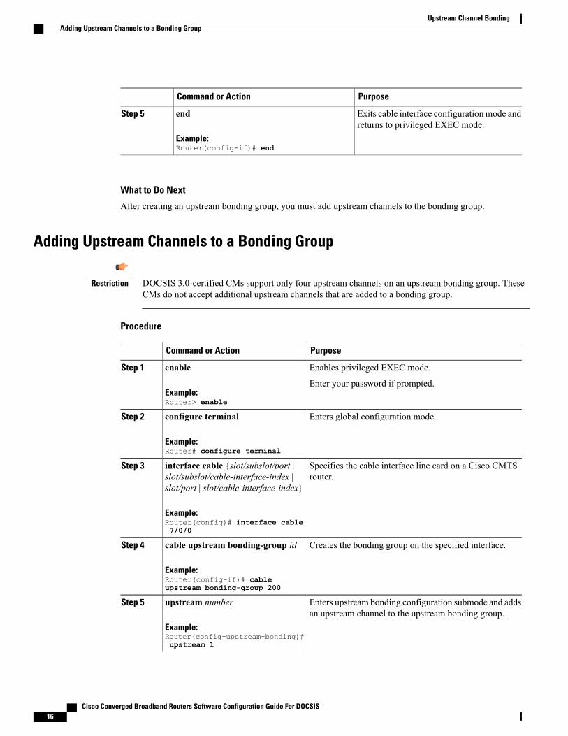
After creating an upstream bonding group, you must add upstream channels to the bonding group.
Adding Upstream Channels to a Bonding Group
DOCSIS 3.0-certified CMs support only four upstream channels on an upstream bonding group. TheseCMs do not accept additional upstream channels that are added to a bonding group.
Restriction
Procedure
PurposeCommand or Action
Enables privileged EXEC mode.enableStep 1
Example:Router> enable
Enter your password if prompted.
Enters global configuration mode.configure terminal
Example:Router# configure terminal
Step 2
Specifies the cable interface line card on a Cisco CMTSrouter.
interface cable {slot/subslot/port |slot/subslot/cable-interface-index |slot/port | slot/cable-interface-index}
Step 3
Example:Router(config)# interface cable7/0/0
Creates the bonding group on the specified interface.cable upstream bonding-group id
Example:Router(config-if)# cableupstream bonding-group 200
Step 4
Enters upstream bonding configuration submode and addsan upstream channel to the upstream bonding group.
upstream number
Example:Router(config-upstream-bonding)#upstream 1
Step 5
Cisco Converged Broadband Routers Software Configuration Guide For DOCSIS16
Upstream Channel BondingAdding Upstream Channels to a Bonding Group

PurposeCommand or Action
Upstream channel needs to be bonded tomac-domain first before adding it to the boundinggroup. For detailed configuration steps of theupstream channel bonding, please refer toConfiguration Example for Upstream ChannelBonding
Note
Starting from Cisco IOS-XE 3.18.0S release, maximumof 16 upstream channels can be configured for each MACDomain, which are divided into two groups:
• Group 1: upstream channel 0-7
• Group 2: upstream channel 8-15
The upstream bonding-group should include all theupstream channels either from Group 1 or Group 2 only.
Exits upstream bonding configuration submode and returnsto privileged EXEC mode.
end
Example:Router(config-upstream-bonding)#end
Step 6
Adding Upstream Channel Ports to a Fiber NodeYou must add upstream channel controllers to a fiber node in order to complete the basic upstream channelbonding configuration on a cable interface line card. The fiber node must contain all upstream and downstreamcontrollers reached by the CMs.
Restriction • Configuration of a fiber node is valid only if all upstream channels inside the fiber node have differentupstream frequencies.
• For any two upstream channels mapped to the upstream cable controllers in the same fiber nodewhere a spectrum group is assigned to one upstream channel, and a frequency is assigned to theother upstream channel, any overlap between any bands associated with the spectrum group of theupstream channel and the frequency of the upstream channel will result in an invalid fiber nodeconfiguration. That is a fixed frequency cannot overlap with another upstream channel’s availablespectrum group bands.
The fiber node configuration must be done in accordance with the physical plant topology.Note
Cisco Converged Broadband Routers Software Configuration Guide For DOCSIS 17
Upstream Channel BondingAdding Upstream Channel Ports to a Fiber Node

Procedure
PurposeCommand or Action
Enables privileged EXEC mode.enableStep 1
Example:Router> enable
• Enter your password if prompted.
Enters global configuration mode.configure terminal
Example:Router# configure terminal
Step 2
Enters fiber node configuration mode.cable fiber-node fiber-node-id
Example:Router(config)# cable fiber-node 2
Step 3
Specifies the upstream channel ports for afiber node.
upstream Upstream-Cable slot/subslot/port
Example:Router(config-fiber-node)# upstreamUpstream-Cable 7/0/1
Step 4
Exits fiber node configuration mode andreturns to privileged EXEC mode.
end
Example:Router(config-fiber-node)# end
Step 5
Configuring the Class-Based Weighted Fair QueuingIn the case of a class-based configuration, allocation of available bandwidth is dependent on the service flowsthat are active in a service class.
Procedure
PurposeCommand or Action
Enables privileged EXEC mode.enableStep 1
Example:Router> enable
Enter your password if prompted.
Enters global configuration mode.configure terminal
Example:Router# configure terminal
Step 2
Cisco Converged Broadband Routers Software Configuration Guide For DOCSIS18
Upstream Channel BondingConfiguring the Class-Based Weighted Fair Queuing

PurposeCommand or Action
Specifies the cable interface line card on aCisco CMTS router.
interface cable {slot/subslot/port |slot/subslot/cable-interface-index | slot/port |slot/cable-interface-index}
Step 3
Example:Router(config)# interface cable 7/0/0
Enables class-based weighted fair queuing.cable upstream qos wfq class
Example:Router(config-if)# cable upstream qos wfqclass
Step 4
Exits cable interface configuration mode andreturns to privileged EXEC mode.
end
Example:Router(config-if)# end
Step 5
Configuring the Activity-Based Weighted Fair QueuingIn the activity-based configuration, allocation of available bandwidth is based on the service class and thetotal number of service flows that are active in a map for the service class.
Procedure
PurposeCommand or Action
Enables privileged EXEC mode.enableStep 1
Example:Router> enable
Enter your password if prompted.
Enters global configuration mode.configure terminal
Example:Router# configure terminal
Step 2
Specifies the cable interface line card on aCisco CMTS router.
interface cable {slot/subslot/port |slot/subslot/cable-interface-index | slot/port |slot/cable-interface-index}
Step 3
Example:Router(config)# interface cable 7/0/0
Enables activity-basedweighted fair queuing.cable upstream qos wfq activity
Example:Router(config-if)# cable upstream qos wfqactivity
Step 4
Cisco Converged Broadband Routers Software Configuration Guide For DOCSIS 19
Upstream Channel BondingConfiguring the Activity-Based Weighted Fair Queuing

PurposeCommand or Action
Exits cable interface configuration mode andreturns to privileged EXEC mode.
end
Example:Router(config-if)# end
Step 5
Configuring Custom Weights for Service Flow PrioritiesThe WFQ functionality helps the Cisco CMTS router share the available bandwidth based on the weight ofthe service flow priorities specified for outstanding requests from an upstream service flow.
Procedure
PurposeCommand or Action
Enables privileged EXEC mode.enableStep 1
Example:Router> enable
Enter your password if prompted.
Enters global configuration mode.configure terminal
Example:Router# configure terminal
Step 2
Specifies the cable interface line card on a CiscoCMTS router.
interface cable {slot/subslot/port |slot/subslot/cable-interface-index | slot/port| slot/cable-interface-index}
Step 3
Example:Router(config)# interface cable 7/0/0
Enables custom weight configuration for all theservice flow priorities in a service class.
cable upstream qos wfq weightspriority0-priority7
Step 4
Example:Router(config-if)# cable upstream qoswfq weights 10 20 30 40 50 60 70 80.
You must specify custom weight valuesfor all the eight service flow priorities (0to 7) when youmodify the default weightsof priorities. The valid range is from 1 to255.
Note
Exits cable interface configuration mode andreturns to privileged EXEC mode.
end
Example:Router(config-if)# end
Step 5
Cisco Converged Broadband Routers Software Configuration Guide For DOCSIS20
Upstream Channel BondingConfiguring Custom Weights for Service Flow Priorities

Configuring the SID ClusterThis section explains how to configure and assign a SID cluster to an upstream bonded service flow.
Configure the cable sid-cluster-group num-of-cluster 2 command to achieve desired upstream bondedspeeds. Alternatively, use a large upstream Max Traffic burst value in the cable modem file (such as 30kB). The Max Concat burst value in the cable modem file need not be changed because DOCSIS 3.0 usescontinuous concatenations and fragmentation (CCF) and can therefore use the default value of 3044 inthe Max Concat field.
Note
If the cable sid-cluster-group command is not used, the router accepts the default SID cluster configuration.By default, only one SID cluster is configured. Similarly, if the cable sid-cluster-switching command isnot used, the router accepts the default SID cluster switchover criterion. That is, only one request can bemade using the SID cluster.
Note
Procedure
PurposeCommand or Action
Enables privileged EXEC mode.enableStep 1
Example:Router> enable
Enter your password if prompted.
Enters global configuration mode.configure terminal
Example:Router# configure terminal
Step 2
Specifies the cable interface linecard on a Cisco CMTS router.
interface cable {slot/subslot/port |slot/subslot/cable-interface-index | slot/port |slot/cable-interface-index}
Step 3
Example:Router(config)# interface cable 7/0/0
Creates a SID cluster group.cable sid-cluster-group [dynamic | req-multiplier value| num-of-cluster number]
Step 4
Example:Router(config-if)# cable sid-cluster-group dynamic
Router(config-if)# cable sid-cluster-groupreq-multiplier 12
Router(config-if)# cable sid-cluster-groupnum-of-cluster 2
Specifies SID cluster switchovercriteria.
cable sid-cluster-switching [max-outstanding-byte value| max-request value | max-time seconds | max-total-bytevalue]
Step 5
Cisco Converged Broadband Routers Software Configuration Guide For DOCSIS 21
Upstream Channel BondingConfiguring the SID Cluster

PurposeCommand or Action
Example:Router(config-if)# cable sid-cluster-switchingmax-outstanding-byte 4444
Router(config-if)# cable sid-cluster-switchingmax-request 222
Router(config-if)# cable sid-cluster-switchingmax-time 444
Router(config-if)# cable sid-cluster-switchingmax-total-byte 67890
Exits cable interface configurationmode and returns to privilegedEXEC mode.
end
Example:Router(config-if)# end
Step 6
What to Do Next
Use the show running-config all command to verify the SID cluster configuration. Following is a sampleoutput of the command:Router# show running-config all...cable sid-cluster-group num-of-cluster 1cable sid-cluster-group dynamiccable sid-cluster-group req-multiplier 4
Configuring the Channel Timeout for a Cable ModemThe channel timeout configuration allows you to specify the maximum time that a CM can spend performinginitial ranging on the upstream channels described in the Registration Response (REG-RSP) and REG-RSP-MPmessages. The default channel timeout value (60 seconds) is automatically configured.
Procedure
PurposeCommand or Action
Enables privileged EXEC mode.enableStep 1
Example:Router> enable
Enter your password if prompted.
Enters global configuration mode.configure terminal
Example:Router# configure terminal
Step 2
Cisco Converged Broadband Routers Software Configuration Guide For DOCSIS22
Upstream Channel BondingConfiguring the Channel Timeout for a Cable Modem
PurposeCommand or Action
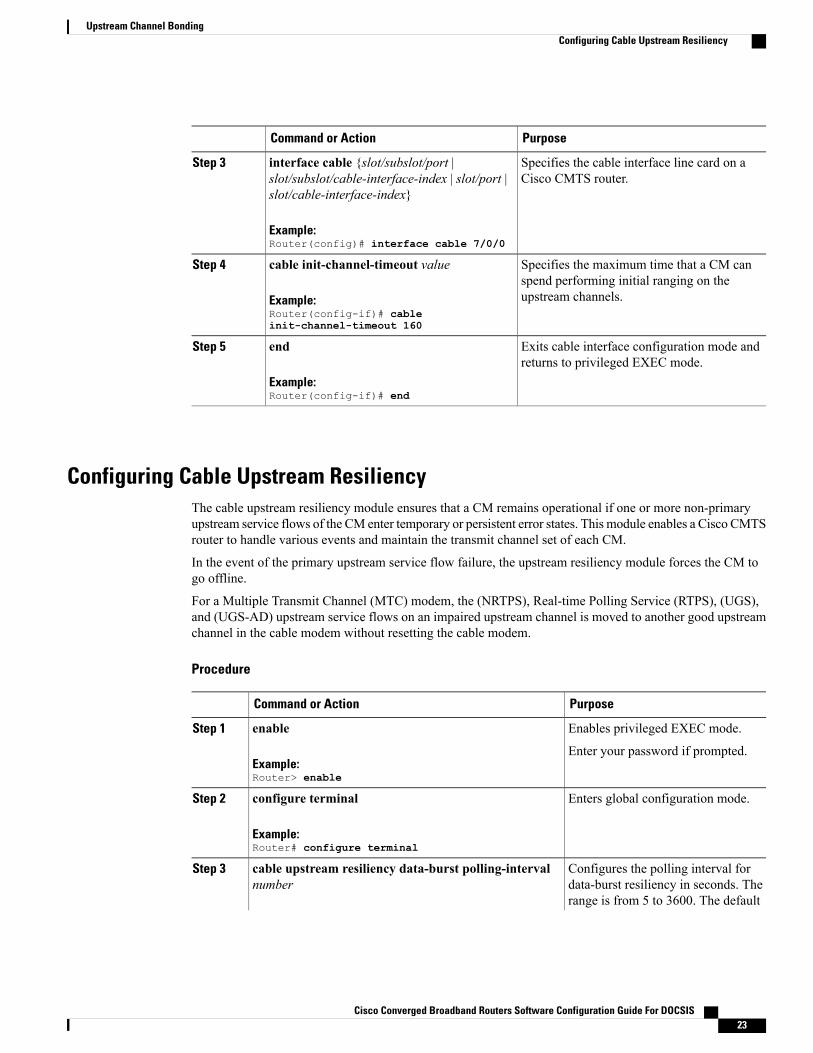
Specifies the cable interface line card on aCisco CMTS router.
interface cable {slot/subslot/port |slot/subslot/cable-interface-index | slot/port |slot/cable-interface-index}
Step 3
Example:Router(config)# interface cable 7/0/0
Specifies the maximum time that a CM canspend performing initial ranging on theupstream channels.
cable init-channel-timeout value
Example:Router(config-if)# cableinit-channel-timeout 160
Step 4
Exits cable interface configuration mode andreturns to privileged EXEC mode.
end
Example:Router(config-if)# end
Step 5
Configuring Cable Upstream ResiliencyThe cable upstream resiliency module ensures that a CM remains operational if one or more non-primaryupstream service flows of the CM enter temporary or persistent error states. This module enables a Cisco CMTSrouter to handle various events and maintain the transmit channel set of each CM.
In the event of the primary upstream service flow failure, the upstream resiliency module forces the CM togo offline.
For a Multiple Transmit Channel (MTC) modem, the (NRTPS), Real-time Polling Service (RTPS), (UGS),and (UGS-AD) upstream service flows on an impaired upstream channel is moved to another good upstreamchannel in the cable modem without resetting the cable modem.
Procedure
PurposeCommand or Action
Enables privileged EXEC mode.enableStep 1
Example:Router> enable
Enter your password if prompted.
Enters global configuration mode.configure terminal
Example:Router# configure terminal
Step 2
Configures the polling interval fordata-burst resiliency in seconds. The
cable upstream resiliency data-burst polling-intervalnumber
Step 3
range is from 5 to 3600. The default
Cisco Converged Broadband Routers Software Configuration Guide For DOCSIS 23
Upstream Channel BondingConfiguring Cable Upstream Resiliency

PurposeCommand or Action
Example:Router(config)# cable upstream resiliencydata-burst polling-interval 60
configuration for polling-interval is60.
Specifies the cable interface line cardon a Cisco CMTS router.
interface cable {slot/subslot/port |slot/subslot/cable-interface-index | slot/port |slot/cable-interface-index}
Step 4
Example:Router(config)# interface cable 7/0/0
Configures upstream resiliency forbonded upstream service flows.
cable upstream resiliency {channel-down-detect number| data-burst snr number ufec number cfec numberhysteresis number |modem-offline-detect number |
Step 5
on-failure {disable-channel | extended-ranging |reset-modem} | sf-move {NRTPS | RTPS | UGS |UGS-AD} }
Example:Router(config-if)# cable upstream resiliencychannel-down-detect 68
Router(config-if)# cable upstream resiliencymodem-offline-detect 16
Router(config-if)# cable upstream resiliencyon-failure disable-channel
Router(config-if)# cable upstream resiliencysf-move NRTPS
Router(config-if)# cable upstream resiliencysf-move RTPS
Router(config-if)# cable upstream resiliencysf-move UGS
Router(config-if)# cable upstream resiliencysf-move UGS-AD
Router(config-if)# cable upstream resiliencydata-burst snr 24 ufec 1 cfec 0 hysteresis 3
Exits cable interface configurationmode and returns to privileged EXECmode.
end
Example:Router(config-if)# end
Step 6
Configuring Rate Limiting on the Cisco cBR-8 CCAP Line CardThe rate limiting functionality is configured by default on the Cisco cBR-8 CCAP line card. However, thedefault configuration can be modified using the cable upstream rate-limit-ccf command.
Cisco Converged Broadband Routers Software Configuration Guide For DOCSIS24
Upstream Channel BondingConfiguring Rate Limiting on the Cisco cBR-8 CCAP Line Card

Procedure
PurposeCommand or Action
Enables privileged EXEC mode.enableStep 1
Example:Router> enable
• Enter your password if prompted.
Enters global configuration mode.configure terminal
Example:Router# configure terminal
Step 2
Configures rate limiting parameters forupstream bonded service flows on a cableinterface line card.
cable upstream rate-limit-ccf [aggregated-burstvalue | aggregated-throughput value | cpu-burstvalue | cpu-threshold value]
Example:Router(config)# cable upstream rate-limit-ccfaggregated-burst 25000
Step 3
Router(config)# cable upstream rate-limit-ccfaggregated-throughput 540000
Router(config)# cable upstream rate-limit-ccfcpu-burst 30
Router(config)# cable upstream rate-limit-ccfcpu-threshold 60
Exits global configuration mode andreturns to privileged EXEC mode.
end
Example:Router(config)# end
Step 4
Enabling Upstream Related Events for CM Status ReportsYou can enable upstream related CM status events only on a cable interface line card. You can enable thefollowing upstream related CM status events per interface using the cable cm-status enable command:
• T4 time-out
• T3 re-tries exceeded
• Successful ranging after T3 re-tries exceeded
For details on how to enable upstream and downstream related CM status events, see the Wideband ModemResiliency feature guide at the following URL:
http://www.cisco.com/en/US/docs/ios/cable/configuration/guide/ubr_wm_resiliency.html
Cisco Converged Broadband Routers Software Configuration Guide For DOCSIS 25
Upstream Channel BondingEnabling Upstream Related Events for CM Status Reports

Modifying the Bonding Group AttributesBonding group attributes are automatically configured for each upstream bonding group. You can modifythem using the attributes command in upstream bonding configuration mode.
Procedure
PurposeCommand or Action
Enables privileged EXEC mode.enableStep 1
Example:Router> enable
Enter your password if prompted.
Enters global configuration mode.configure terminal
Example:Router# configure terminal
Step 2
Specifies the cable interface line card on aCisco CMTS router.
interface cable {slot/subslot/port |slot/subslot/cable-interface-index | slot/port |slot/cable-interface-index}
Step 3
Example:Router(config)# interface cable 7/0/0
Creates the bonding group on the specifiedcable interface and enters the upstream bondingconfiguration mode.
cable upstream bonding-group id
Example:Router(config-if)# cable upstreambonding-group 200
Step 4
Modifies the attribute value for the specifiedbonding group.
attributes value
Example:Router(config-upstream-bonding)#attributes eeeeeeee
Step 5
Exits upstream bonding configuration modeand returns to privileged EXEC mode.
end
Example:Router(config-upstream-bonding)# end
Step 6
Modifying the Ranging Poll Interval on Upstream ChannelsYou can change the default ranging poll interval (20 seconds) on upstream channels using the cable upstreamranging-poll command in cable interface configuration mode. You can also specify the T4 timeout multipliervalue using this command.
For information on T4 Multiplier, see T4 Multiplier, on page 7 .
Cisco Converged Broadband Routers Software Configuration Guide For DOCSIS26
Upstream Channel BondingModifying the Bonding Group Attributes

We recommend that you do not modify the default ranging poll interval unless required. With the defaultconfiguration, a DOCSIS 2.0 CM in non-MTC mode performs ranging on one upstream channel every20 seconds.
Note
Procedure
PurposeCommand or Action
Enables privileged EXEC mode.enableStep 1
Example:Router> enable
Enter your password if prompted.
Enters global configuration mode.configure terminal
Example:Router# configure terminal
Step 2
Specifies the cable interface line card on a CiscoCMTS router.
interface cable {slot/subslot/port |slot/subslot/cable-interface-index | slot/port| slot/cable-interface-index}
Step 3
Example:Router(config)# interface cable 7/0/0
Specifies the ranging poll interval for upstreamchannels.
cable upstream ranging-poll [interval value| t4-multiplier timeout_value]
Step 4
Example:
Router(config-if)# cable upstream
If t4-multiplier timeout_value is notconfigured, then the CMTS uses the theT4 timeout of the modem. For example,if the T4 timeout of the modem is 90seconds, then the CMTS will apply 3 asT4 multiplier for the modem.
Note
ranging-poll interval 24000t4-multiplier 4
Exits cable interface configuration mode andreturns to privileged EXEC mode.
end
Example:Router(config-if)# end
Step 5
Configuring the Reduced Channel Set AssignmentYou need to configure the transmit power offset budget to enable the Cisco CMTS router to reduce upstreamchannel set assignment based on the total power budget of the CM.
Cisco Converged Broadband Routers Software Configuration Guide For DOCSIS 27
Upstream Channel BondingConfiguring the Reduced Channel Set Assignment

The threshold value specified for the power budget offset (max-channel-power-offset) must be less thanthe power threshold value (power-adjust continue) that determines the value of the Ranging Status fieldin the Ranging Response (RNG-RSP) messages that the Cisco CMTS router sends to the CM. You canspecify the power threshold value using the cable upstream power-adjust command.
Note
Before You Begin
• Configure extended transmit power using the cable tx-power-headroom command in global configurationmode.
• Ensure that corresponding static bonding groups are configured.
Procedure
PurposeCommand or Action
Enables privileged EXEC mode.enableStep 1
Example:Router> enable
Enter your password if prompted.
Enters global configuration mode.configure terminal
Example:Router# configure terminal
Step 2
Specifies the cable interface line card on aCisco CMTS router.
interface cable {slot/subslot/port |slot/subslot/cable-interface-index | slot/port |slot/cable-interface-index}
Step 3
Example:Router(config)# interface cable 7/0/0
Specifies the power offset value for upstreamchannels.
cable upstream max-channel-power-offsetdB-value
Example:Router(config-if)# cable upstreammax-channel-power-offset 2
Step 4
Exits cable interface configurationmode andreturns to privileged EXEC mode.
end
Example:Router(config-if)# end
Step 5
Configuring DOCSIS Extended Transmit Power FeatureThe DOCSIS Extended Transmit Power feature is enabled by default on the Cisco CMTS. However, thedefault configuration can be modified using the cable upstream ext-power command.
Cisco Converged Broadband Routers Software Configuration Guide For DOCSIS28
Upstream Channel BondingConfiguring DOCSIS Extended Transmit Power Feature

Procedure
PurposeCommand or Action
Enables privileged EXEC mode.enableStep 1
Example:Router> enable
Enter your password if prompted.
Enters global configuration mode.configure terminal
Example:Router# configure terminal
Step 2
Specifies the cable interface line card on a CiscoCMTS router.
interface cable {slot/subslot/port |slot/subslot/cable-interface-index | slot/port| slot/cable-interface-index}
Step 3
Example:Router(config)# interface cable 7/0/0
Enables the DOCSIS Extended Transmit Powerfeature on the Cisco CMTS.
cable upstream ext-power
Example:
Router(config-if)# cable upstreamext-power
Step 4
Using the no form of this command disables theDOCSIS Extended Transmit Power feature.
Exits interface configuration mode and returns toprivileged EXEC mode.
end
Example:Router(config-if)# end
Step 5
Troubleshooting TipsThe following debug commands help you troubleshoot an improper upstream channel bonding configurationand its related features:
• debug cable cm-status—Provide debugging information about CM status messages on the Cisco CMTSrouters.
• debug cable mdd—Provides debugging information about MAC domain descriptor (MDD).
• debug cable md-sg—Provides information about service group debugging messages.
• debug cable ubg—Provides debugging information about upstream bonding groups.
Cisco Converged Broadband Routers Software Configuration Guide For DOCSIS 29
Upstream Channel BondingTroubleshooting Tips

Configuration Example for Upstream Channel BondingThe following example shows how to configure the basic upstream channel bonding on the Cisco cBR-8CCAP line card interface 7/0/0 on the Cisco cBR-8 router:
controller Upstream-Cable 7/0/0us-channel 0 frequency 10000000us-channel 0 channel-width 3200000 3200000us-channel 0 ingress-noise-cancellation 50us-channel 0 docsis-mode atdmaus-channel 0 minislot-size 2us-channel 0 modulation-profile 221us-channel 0 equalization-coefficientno us-channel 0 shutdownus-channel 1 frequency 16400000us-channel 1 channel-width 6400000 6400000us-channel 1 ingress-noise-cancellation 50us-channel 1 docsis-mode atdmaus-channel 1 minislot-size 1us-channel 1 modulation-profile 221us-channel 1 equalization-coefficientno us-channel 1 shutdownus-channel 2 frequency 22800000us-channel 2 channel-width 6400000 6400000us-channel 2 docsis-mode atdmaus-channel 2 minislot-size 1us-channel 2 modulation-profile 221us-channel 2 equalization-coefficientno us-channel 2 shutdownus-channel 3 frequency 29200000us-channel 3 channel-width 6400000 6400000us-channel 3 docsis-mode atdmaus-channel 3 minislot-size 1us-channel 3 modulation-profile 221us-channel 3 equalization-coefficientno us-channel 3 shutdownus-channel 4 channel-width 1600000 1600000us-channel 4 docsis-mode tdmaus-channel 4 minislot-size 4us-channel 4 modulation-profile 21us-channel 4 shutdownus-channel 5 channel-width 1600000 1600000us-channel 5 docsis-mode atdmaus-channel 5 minislot-size 4us-channel 5 modulation-profile 221us-channel 5 shutdown!
interface Cable7/0/0load-interval 30downstream Integrated-Cable 7/0/0 rf-channel 0downstream Integrated-Cable 7/0/0 rf-channel 8downstream Integrated-Cable 7/0/0 rf-channel 16upstream 0 Upstream-Cable 7/0/0 us-channel 0upstream 1 Upstream-Cable 7/0/0 us-channel 1upstream 2 Upstream-Cable 7/0/0 us-channel 2upstream 3 Upstream-Cable 7/0/0 us-channel 3no cable upstream 0 equalization-error-recoveryno cable upstream 1 equalization-error-recoveryno cable upstream 2 equalization-error-recoveryno cable upstream 3 equalization-error-recoverycable upstream 7 attribute-mask 1FFcable upstream bonding-group 1upstream 0upstream 1upstream 2attributes 80000000cable bundle 1
Cisco Converged Broadband Routers Software Configuration Guide For DOCSIS30
Upstream Channel BondingConfiguration Example for Upstream Channel Bonding

cable map-advance static 2000cable sync-interval 121cable reduction-mode mta-battery enablecable privacy accept-self-signed-certificateend
cable fiber-node 1description Feed Mac Domain: Cable7/0/0downstream Integrated-Cable 7/0/0upstream Upstream-Cable 7/0/0
Bonded channels are typically from the same connector; however, channels from different connectors inthe same MAC domain can also be bonded together. A single MAC domain can support multiple channelbonding groups.
Note
Up to 8 frequencies can be stacked to one upstream-cable controller. Once the upstream-cable controllerhas 8 frequencies stacked, no more frequency left for the adjacent upstream-cable controller.
Note
Example: Enabling MTC Mode for a Single CM Using the CM ConfigurationFile
The following example shows how to enable the MTC required attribute using the CM configuration file:
03 (Net Access Control) = 1Unknown Type 005 = 01 01 0118 (Maximum Number of CPE) = 424 (Upstream Service Flow Encodings)
S01 (Service Flow Reference) = 1S06 (QoS Parameter Set Type) = 7S10 (Min Reserved Traffic Rate)= 500000
25 (Downstream Service Flow Encodings)S01 (Service Flow Reference) = 2S06 (QoS Parameter Set Type) = 7S10 (Min Reserved Traffic Rate) = 1000000
29 (Privacy Enable) = 043 (Vendor Specific Options)
S08 (Vendor ID) = ff ff ffS009 (Unknown sub-type) = 03 04 80 00 00 00
Verifying the Upstream Channel Bonding ConfigurationUse the following show commands to verify the upstream channel bonding configuration:
• show cable mac-domain upstream-service-group
• show cable fiber-node
• show interface cable upstream
• show interface cable service-flow
• show cable modem
Cisco Converged Broadband Routers Software Configuration Guide For DOCSIS 31
Upstream Channel BondingExample: Enabling MTC Mode for a Single CM Using the CM Configuration File

To verify the runtime statistics of the upstream service group on a cable interface line card, use the showcable mac-domain upstream-service-group command.
To verify the configuration of a fiber node, use the show cable fiber-node command.
To verify the bonding groups configured on a cable interface line card, use the show interface cable upstreamcommand.
To verify upstream bonding information on a cable interface line card, use the show interface cableservice-flow command.
To verify the transmit power levels on a CM, use the show cable modem command.
Verifying Weighted Fair Queuing for Upstream Service FlowsTo verify WFQ parameters configured for upstream service flows on a cable interface line card, use the showinterface cable mac-scheduler command.
Verifying Rate Limiting for Upstream Bonded Service FlowsTo verify the rate limiting criteria configured on the Cisco cBR8 CCAP line card for upstream bonded serviceflows, use the show cable rate-limit-ccf command.
The show cable rate-limit-ccf command is applicable only to the Cisco cBR8 CCAP cable interface linecard.
Note
Verifying Extended Power TransmissionTo verify that a CM is transmitting at a higher power level, use the show cable modem command.
To list all the CMs that are transmitting at higher power level, use the show cable modem extended-powercommand.
Additional ReferencesThe following sections provide references related to the Upstream Channel Bonding feature.
Cisco Converged Broadband Routers Software Configuration Guide For DOCSIS32
Upstream Channel BondingVerifying Weighted Fair Queuing for Upstream Service Flows

Technical Assistance
LinkDescription
http://www.cisco.com/techsupportThe Cisco Support website provides extensive onlineresources, including documentation and tools fortroubleshooting and resolving technical issues withCisco products and technologies.
To receive security and technical information aboutyour products, you can subscribe to various services,such as the Product Alert Tool (accessed from FieldNotices), the Cisco Technical Services Newsletter,and Really Simple Syndication (RSS) Feeds.
Access to most tools on the Cisco Support websiterequires a Cisco.com user ID and password.
Feature Information for Upstream Channel BondingUse Cisco Feature Navigator to find information about platform support and software image support.Cisco Feature Navigator enables you to determine which software images support a specific software release,feature set, or platform. To access Cisco Feature Navigator, go to http://tools.cisco.com/ITDIT/CFN/. Anaccount on http://www.cisco.com/ is not required.
The below table lists only the software release that introduced support for a given feature in a givensoftware release train. Unless noted otherwise, subsequent releases of that software release train alsosupport that feature.
Note
Table 6: Feature Information for Upstream Channel Bonding
Feature InformationReleasesFeature Name
This feature was introduced on theCisco cBR Series ConvergedBroadband Router.
Cisco IOS-XE Release 3.15.0SUpstream Channel Bonding
Cisco Converged Broadband Routers Software Configuration Guide For DOCSIS 33
Upstream Channel BondingFeature Information for Upstream Channel Bonding

Cisco Converged Broadband Routers Software Configuration Guide For DOCSIS34
Upstream Channel BondingFeature Information for Upstream Channel Bonding
Related Documents