UPRR Tie Treating Plant, The Dalles, OR DNAPL Recovery Progress Anne Walsh/UPRR Site Remediation Manager Jeff Gentry/CH2M Principal Engineer October 2017

Welcome message from author
This document is posted to help you gain knowledge. Please leave a comment to let me know what you think about it! Share it to your friends and learn new things together.
Transcript

1
UPRR Tie Treating Plant, The Dalles, OR DNAPL Recovery Progress
Anne Walsh/UPRRSite Remediation Manager
Jeff Gentry/CH2MPrincipal Engineer
October 2017

2
• Historic wood treating operations led to releases of creosote oil to the environment– This DNAPL is difficult to treat
• In 1997, a multi-faceted remedy was implemented to control migration of impacted groundwater and remove DNAPL to the extent practicable
• Shutdown of DNAPL recover systems is challenging– Continual recovery– Need to evaluate how to meet Remedial Action Objectives (RAO)
• No vertical or horizontal migration
• Transmissivity and pool height were determined to be an effective way to evaluate if RAO have been met
Overview

3
Site OverviewRemedial Action Summary
1992 Soil Removal
1995 Sediment Cap
1995 to 2004Groundwater Remedy
Soil Remedy1997 - Institutional Controls

4
• DNAPL released from process ponds and retort building
Cross Section
Alluvium
Flow Top
Columnar Basalt
Freeway
River
• DNAPL accumulated in the basalt flow top
• DNAPL contained by ridge of columnar basalt in park
DNAPL

5
• Upper geology consists of three layers:
DNAPL Recovery from Fractured RockGeology from Adjacent Area Where Exposed
– Alluvium– Basalt Flow Top– Columnar Basalt
• DNAPL recovery is focused on the fractured flow top

6
• The groundwater remedy is characterized by two separate areas– DNAPL source area– Dissolved plume area
• Before remedy, wells in Riverfront Park were all above water quality standards for surface water
• 1996 remedy required– Containment of DNAPL source area and
groundwater restoration if technically feasible• Technical Impracticability waiver obtained for
source area– Monitoring of dissolved area plume– Achieve DNAPL RAO
Groundwater Remedy OverviewImpact Areas and Remedial Objectives
7
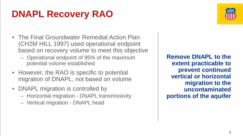
Remove DNAPL to the extent practicable to
prevent continued vertical or horizontal
migration to the uncontaminated
portions of the aquifer
• The Final Groundwater Remedial Action Plan (CH2M HILL 1997) used operational endpoint based on recovery volume to meet this objective– Operational endpoint of 95% of the maximum
potential volume established
• However, the RAO is specific to potential migration of DNAPL, not based on volume
• DNAPL migration is controlled by– Horizontal migration - DNAPL transmissivity– Vertical migration - DNAPL head
DNAPL Recovery RAO

8
• Design hydraulic containment system to capture source area and recover DNAPL– Groundwater model used for capture
design
Groundwater Remedy OverviewDesign Objectives
• Design DNAPL recovery systems using water-flooding method (Sale and Applegate 1997)– Recover DNAPL and reinject water– Control iron fouling– Install DNAPL recovery systems
sequentially
Module 1
Module 2
Module 3
– Water treatment for PAH’s, arsenic, and iron– NPDES discharge to creek out of capture
area

9
• Groundwater extraction results in DNAPL upconing
Water Flooding Enhances DNAPL Recovery
• DNAPL removal is controlled to prevent cutoff of DNAPL flow paths
• Water reinjection increases hydraulic gradients to well and increases rate of DNAPL recovery

10
Process Flow Diagram Pressurized Oil/Water Separators
• Closed loop system with DNAPL recovery, storage, and reinjection
System ComparisonDNAPL Recovery Equipment
M
O
Transfer to DNAPL Storage F F F
O/W Separator
Other Extraction Wells
Typical Extraction Well
Injection Wells

11
Hydraulic Containment System
• System provides hydraulic containment of source area and DNAPL recovery
• Started in 1996• Equipment
– Originally 6 wells; expanded to 10 wells; now back to 6
– Water treatment plant– Effluent discharge
• Nearly 60,000 gallons of DNAPL recovered
Groundwater FlowDirection

12
Module 1 DNAPL Recovery System
• Module 1 constructed on the upgradient edge of DNAPL source area
• Started in 1999• Equipment:
– 8 extraction wells – 1 pressurized oil water
separator– 8 injection wells
• Operated ~10 years• Over 12,000 gallons of
DNAPL recovered

13
Module 2/3 DNAPL Recovery System
• Module 2 constructed in center of DNAPL area
• Started in 2004• Equipment
– 11 extraction wells– 3 pressurized oil water
separators – 8 injection wells
• Over 50,000 gallons of DNAPL recovered

14
NAPL Site Conceptual Model
• DNAPL is in fractures of basalt flow top
• Module 1 has depleted upgradient pooled NAPL
• Hydraulic Containment System has depleted downgradient pooled NAPL
• Mod 2/3 is still in operation
Alluvium
Flow Top
Columnar Basalt
Freeway
River
DNAPL
Module 2/3 Wells Hydraulic
Containment System Wells
Module 1 Wells
Injection WellsExtraction Wells

15
• Transmissivity changes were observed in 2008 in DNAPL recharge data
DNAPL TranmissivityEarly Observations
– Same well recharged in two years in 2006
– DNAPL recharge rates of one month in 1999

16
Transmissivity Analysis Program
• DNAPL transmissivity testing program– Historic data– Planned tests
• Measurements at different times for different wells– 1 hydraulic containment well– 6 Module 1 wells– 4 Module 2/3 wells

17
REMEDY PERFORMANCE

18
Remedy Performance Metrics
• Hydraulic containment of DNAPL source area– Capture analysis using water levels– Down gradient concentration monitoring
• Prevent horizontal DNAPL migration– Recovery endpoint– DNAPL transmissivity
• Prevent vertical migration of DNAPL– DNAPL head on columnar basalt

19
• Water level measurements used to assess hydraulic capture
• Results have been consistent with capture of the leading edge of the dissolved groundwater plume
Hydraulic Capture

20
Columbia River
Riverfront Park
Interstate 84
Dissolved Plume ReductionDowngradient Results Below Ambient Groundwater Criteria
Arsenic
April '9
8
April '0
7
April '1
5
Con
cent
ratio
n (
g/L)
0
50
100
150
200
250
300
PCP
April '9
8
April '0
7
April '1
5
Con
cent
ratio
n (
g/L)
0
10
20
30
40
50
60CPAHs
April '9
8
April '0
7
April '1
5
Con
cent
ratio
n (
g/L)
0
1
2
3
4
5
6
Naphthalene
April '9
8
April '0
7
April '1
5
Con
cent
ratio
n (
g/L)
0100200300400500600700
Freshwater Screening Criteria

21
Hydraulic Containment Module 1
System Recovery Curves
Module 2/3
• Current Status– Hydraulic containment endpoint achieved, operated for hydraulic containment– Module 1 endpoint achieved in 2009 – system abandoned– Module 2/3 endpoint not achieved, operation continues
• Over 120,000 gallons of DNAPL recovered from fractured rock

22
Production Production and Transmissivity
Combined SystemsOverall Production and Decline Curve
Data analysis method: Reyenga, Lisa. 2016. “Estimating Expected Ultimate Recovery.” Applied NAPL Science Review. Vol. 6, Issue 2, July.

23
Example Top of Columns Removal Objectives
• Prevent downward migration of DNAPL
• Analytical calculations show it takes five feet of head on the columns for downward migration
• Prior to remediation, up to 18 feet of head was observed in some locations
DNAPL Head on Columnar Basalt

24
Hydraulic Containment Module 1
Before and after recoveryDNAPL Head on Columnar Basalt
Module 2/3
• Static DNAPL levels above columnar basalt– Range up to 18 feet
• Analysis is subjective since the interface between the flow top and columnar basalt is transitional and irregular
Early Operation
-15
-10
-5
0
5
10
15
20
25
Hydraulic Containment System
Early Operation
-15
-10
-5
0
5
10
15
20
25
M d l 1
Early Operation
-15
-10
-5
0
5
10
15
20
25
Module 2/3

25
Early Operation
-15
-10
-5
0
5
10
15
20
25
All Modules
Early Operation Recent Operation
-15
-10
-5
0
5
10
15
20
25
All Modules
• Median of all wells near 5 feet DNAPL head in early operation
• Current median of all wells near zero• Current focus on two wells with
higher heads
Current DNAPL Head Levels

26
• 30 years of groundwater remedy operation have achieved the RAOs for the site:– Source area hydraulically contained– Downgradient plume remediated– Horizontal DNAPL migration abated– Vertical DNAPL migration abated
• DNAPL recovery will continue to achieve:– Operational endpoint of Module 2/3 with new endpoint criteria– DNAPL head reduction in select wells
Summary and Path Forward

Related Documents


