207203-0002 207203-0002 uPrint ® and uPrint ® Plus Personal 3D Printers User Guide

Welcome message from author
This document is posted to help you gain knowledge. Please leave a comment to let me know what you think about it! Share it to your friends and learn new things together.
Transcript

uPrint® and uPrint® Plus
Personal 3D Printers
User Guide
207203-0002207203-0002

Legal Notice© 2011 Stratasys, Inc. All rights reserved. The information in this document is subject to change without notice. STRATASYS, INC. MAKES NO WARRANTY OF ANY KIND WITH REGARD TO THIS MATERIAL, INCLUDING, BUT NOT LIMITED TO, THE IMPLIED WARRANTIES OF MERCHANTABILITY AND FITNESS FOR A PARTICULAR PURPOSE. Stratasys, Inc. shall not be liable for errors contained herein or for incidental or consequential damages in connection with the furnishing, performance, or use of this Material.
Stratasys, Dimension, uPrint, uPrint Plus and CatalystEX are registered trademarks of Stratasys, Inc.
ABSplus is a trademark of Stratasys, Inc.
Windows XP, Windows Vista and Windows 7 are registered trademarks of their respective owners.
.
Table of Contents
1 Introduction...............................................................................................................................1How to use this guide ..............................................................................................1Learn More!............................................................................................................1Safety precautions ...................................................................................................2
2 Overview..................................................................................................................................3Finding more information ........................................................................................9
3 Setup ......................................................................................................................................10Installing software .................................................................................................10Networking the printer ...........................................................................................10Establishing network communication with the printer ..................................................11Installing Firmware on printer..................................................................................14Adding the second Material Bay .............................................................................14
4 Operation ...............................................................................................................................19Display panel and keypad......................................................................................19System firmware overview ......................................................................................20CatalystEX overview ..............................................................................................21Processing your STL file for printing .........................................................................22Building a part ......................................................................................................24The display panel during build................................................................................25Chamber Lights .....................................................................................................25Pausing a build .....................................................................................................25Resuming after pause.............................................................................................25Canceling a build..................................................................................................26Removing a completed part ....................................................................................26Removing support material .....................................................................................27Emptying the purge bucket .....................................................................................27Replacing material for single material bay................................................................28Replacing material for dual material bays ................................................................29Material bay LEDs .................................................................................................30Replacing material spools.......................................................................................30Storing material spools...........................................................................................30Auto power down .................................................................................................32Powering off .........................................................................................................32Resuming operations from Standby mode.................................................................33Updating printer firmware: .....................................................................................33
i

5 Maintenance ...........................................................................................................................34Startup kit tools .................................................................................................... 34Preventive Maintenance ........................................................................................ 34Daily ...................................................................................................................34500 Hour maintenance ......................................................................................... 35Tip wipe assembly.................................................................................................35Tip shield replacement ...........................................................................................37Remove debris from the Filament Present switch ........................................................392000 Hour maintenance ....................................................................................... 41Tip replacement and calibration ..............................................................................41Chamber light bar replacement...............................................................................47
6 Troubleshooting ......................................................................................................................48Troubleshooting ....................................................................................................48Fault determination codes.......................................................................................49Exporting printer configuration (.cfg) file ..................................................................49Cycling power ......................................................................................................50Diagnosing loss of extrusion ...................................................................................50Clogged tip ..........................................................................................................51Material Jam.........................................................................................................52Recovering from loss of extrusion.............................................................................54
7 Support...................................................................................................................................58Registration ..........................................................................................................58Customer Support..................................................................................................58
8 Recycling ................................................................................................................................59Removing the EEproms from the material guides........................................................60Removing the desiccant from the material spool ........................................................60
9 Printer Specifications ...............................................................................................................61Physical specifications............................................................................................61Facility specifications .............................................................................................61Workstation specifications......................................................................................62Power specifications ..............................................................................................62Environmental specifications ...................................................................................62Acoustic specifications ...........................................................................................62
10 Supplemental Information........................................................................................................63Stratasys Limited Warranty Statement ......................................................................63Declaration of Conformity ......................................................................................65Regulatory and environmental information................................................................66
11 Appendix............................................................................................................................... A1Uninterruptible Power Supply (UPS) Use and Installation............................................ A1
ii

1 Introduction
uPrint® and uPrint® Plus are designed with ultimate simplicity in mind. The printer enables you to build parts quickly and easily, even if you’ve never used a 3D printer before.
The printers build models with ABSplusTM material so parts are strong and durable. ABSplus material also ensures you will be able to drill, tap, sand and paint your creations. With Soluble Support Technology (SST), your completed parts are quickly available for review and test. uPrint and uPrint Plus are an innovative combination of proprietary hardware, software and material technology.
Welcome to the new dimension of 3D modeling!
How to use this guideThis User Guide is laid out in easy to follow sections which cover Set-up, Operation, Maintenance, and Troubleshooting. Read each section carefully so that you will get the best performance from your printer.
Throughout this User Guide, text representing Interface Messages that appear on the display panel are presented in a bold font.
Learn More!An electronic User Guide is available on the startup CD. This guide provides information on the following topics:
• Troubleshooting information• Important safety notices and regulatory information• Information about supported printing supplies• Detailed user instructions
You can also find more information at:
http://www.dimensionprinting.com/uprint/customerinfo.html
1

Safety precautionsThe following precautions ensure the proper use of the printer and prevent the printer from being damaged. Follow these precautions at all times.
• Use the power supply voltage specified on the nameplate. Avoid overloading the printer’s electrical outlet with multiple devices.
• Ensure the printer is well-grounded. Failure to ground the printer may result in electrical shock, fire and susceptibility to electromagnetic interference.
• Before disassembling or repairing the printer yourself, contact your local Service Representative. See Support section of User Guide.
• Use only the power cord supplied with the printer. Do not damage, cut or repair the power cord. A damaged power cord has risk of fire and electric shock. Replace a damaged power cord with an approved power cord.
• Do not allow metal or liquids to touch the internal parts of the printer. Doing so may cause damage, fire, electric shock or other serious hazards.
• Power off the printer and disconnect the power cord from the power outlet in any of the following cases:• If there is smoke or an unusual smell coming from the printer.• If the printer is making an unusual noise not heard during normal operation.• A piece of metal or a liquid touches the internal parts of the printer.• During an electrical (thunder/lightning) storm• During a power failure
The following classifications are used throughout this guide.
CAUTION: Indicates a potentially hazardous situation which, if not avoided, may result in minor or moderate injury.
WARNING: Indicates a potentially hazardous situation which, if not avoided, could result in serious injury.
Hot Surface: The hot surface sign indicates the presence of devices with high temperatures. Always use extra care, and wear safety gloves, when working around heated components
Gloves: When performing some maintenance procedures, the machine may be hot and gloves will be required to avoid burns.
Safety Glasses: Wear safety glasses to avoid injury to your eyes.
Lifting Hazard: Lift with two or more people to avoid serious injury.
Recycle: Use proper recycling techniques for materials and packaging.
ESD: Use standard electrostatic discharge (ESD) precautions when working on or near electrical components.
2

2 Overview
uPrint and uPrint Plus build models from CAD STL files. The printer builds three-dimensional parts by extruding a bead of ABS material through a computer-controlled extrusion head, producing high quality parts that are ready to use immediately after completion.
uPrint and uPrint Plus consist of two primary components — the 3D printer and material bay. Catalyst®EX is the preprocessing software that runs on Windows XP Pro, Windows Vista or Windows 7 platforms.
uPrint builds a maximum part size of 203 x 152 x 152 mm (8 x 6 x 6 in). uPrint Plus builds a maximum part size of 203 x 203 x 152 mm (8 x 8 x 6 in). Each material carrier contains 492 cc (30 cu. in.) of usable material — enough to build continuously for about 48 hours without reloading. You can add an optional second material bay for extended build times.
3

Figure 1 Front and left side view of printer.
1 Display Panel
2 Material Bay, Support Side
3 Optional Material Bay, Support Side
4 Optional Material Bay, Model Side
5 Material Bay, Model Side
6 Power ON/OFF Switch
Front view Left side view
2
3 4
5
1 6
4

Figure 2 Interior chamber - front view
1 Extrusion Head
2 Tip wipe assembly
3 Purge bucket
4 Z stage platen
5 Modeling base retainers (x2)
6 Modeling base
7 Z stage lead screw
8 Z stage guide rods
9 Extrusion Tips
2
5
3
4
6
7
8
9
1
5

Figure 3 Rear view of printer
1 Model Material Y Connector 9 Support Material Tube
2 Model Material Tube 10 UPS Connection
3 AC Power Cord Connector 11 Material Bay Cable Connector
4 Circuit Breaker 12 RJ-45 Network Connector
5 Material Bay 13 Diagnostics Cable Connector
6 Optional Model Material Tube 14 Material Bay Communications Cable
7 Optional Material Bay 15 Optional Material Bay Communications Cable
8 Support Material Y Connector 16 Optional Support Material Tube
Note: To avoid damage to the printer from an uncontrolled power loss, installation of a UPS (Uninterruptible Power Supply) is recommended.
1
2
3
4
5
6
7
8
9
10
11
12
13
14
15
16
6

Figure 4 Material carriers
Figure 5 Modeling base
CAUTION: DO NOT reuse modeling bases. If a modeling base is reused, calibration errors, poor part quality, and loss of extrusion may occur. Additional modeling bases are available from your reseller.
Support material carrierModel material carrier
Modeling base
7

Figure 6 Startup Kit contents
1 Crossover cable (orange)
2 Network cable (blue)
3 Tip replacement kit (A. Support tip B. Model tip C. 8 Tip shields D. 4 Tip wipe assemblies)
4 Model material spool
5 CatalystEX CD
6 1/8 inch T-Handle wrench (red)
7 System Software CD
8 User Guide CD
9 Support material spool
10 7/64 inch T-Handle wrench (yellow)
11 Needle nose pliers
12 10x magnifier loupe
13 Cutters
14 Wire brush
15 Gloves
16 Power cord (Euro)
17 Power cord (US)
2
1
3
65
17 16 15
11
10
13
14
7
4 9
A BC
D
8
12
8

Finding more information CatalystEX Online Help
Simple operating instructions for CatalystEX are available in CatalystEX Dynamic Help. You can also see CatalystEX Help from the menu bar - Help>Contents
World Wide Web
Additional information is available at:http://www.dimensionprinting.com/uprint/customerinfo.html
9
3 Setup
Set up the printer and material bay(s) per assembly instructions included with printer.
Installing softwareThere are two software programs that work with uPrint and uPrint Plus:
1. CatalystEX, installed on your workstation, processes the STL files for printing and communicates with the printer from your workstation.
2. System firmware, the operating software installed on the printer, controls printer functions.
Installing CatalystEX:1. Locate the Startup CD from startup kit and insert into workstation (PC).
2. Click the Install CatalystEX: button.
3. Follow prompts to finish loading CatalystEX on the workstation.
Installing firmware to the workstation:1. Click the Install Firmware button to load firmware to your workstation. You will be asked to
load this firmware to your printer later.2. Follow prompts to finish installing firmware on the workstation.
3. Install firmware to the printer, see “Installing Firmware on printer” on page 14
Networking the printerThere are two methods of connecting your printer to your workstation, over a network or with a direct connection to your workstation.
Connecting through a network:1. Locate the network cable (blue) from the startup kit.
2. Connect the network cable between the printer and the network hub.
3. Establish communication, see “Establishing communication on a dynamic network:” on page 11 if you have a dynamic network, or see “Establishing communication on a static network:” on page 11 if you have a static network.
Connecting directly to a workstation:1. Locate the crossover cable (orange) from the startup kit.
2. Connect the crossover cable between the printer and the network port on your workstation.
3. Establish communication, see “Establishing communication on a static network:” on page 11
10
Establishing network communication with the printerYou will need to establish network communication between your workstation and printer before you can send files to be built. How you establish this communication with an IP address is dependent upon how your network and workstation are configured. If your network is configured for DHCP (Dynamic Host Configuration Protocol), your DHCP server will automatically assign a Dynamic IP address to your printer. This is the default setting for your printer and commonly used in large networks. In some situations you may need to manually enter a Static IP address for your printer and record the IP address in the CatalystEX software. Static IP addresses are frequently used for smaller networks or for direct connection between your workstation and printer. Follow the instructions below to configure your workstation and network.
Establishing communication on a dynamic network:If you are on a dynamic network (or not sure of your network type) follow these steps to allow CatalystEX to find your printer and establish communication.
1. Connect a network cable between the printer and a network hub.
2. Make sure the printer is ON and determine the Unique Device Name (UDN) for your printer.
a. From Idle (or Ready to Build), press Maintenance on the display panel. The display will show Maintenance and the software version.
b. From the display panel press System.c. From the display panel press Set Network. The top window will
display: Network Admin - Dynamic IP Address; UDN.d. The Unique Device Name (UDN) for your printer is listed here. This
is preset at the factory and cannot be changed.
3. From your workstation, start the CatalystEX.
4. From the General tab, click the Manage 3D Printers button.
5. Click the Add from Network button in the lower right corner of the window.
6. A new window, Add 3D Printer, should list your printer in the main window (identified by its UDN). Click on the printer in this window and enter a name and location in the lower portion of the window.
7. Click Add Printer and you are ready to print. Close the Add 3D Printer window.
Establishing communication on a static network:If you are using a static network or connecting the printer directly to a workstation, you will need to enter the static IP address information into the workstation and the printer. If you are using a static network and your computer already has network access, see “Setting the static network on printer:” on page 131. Set the static IP address information in the workstation:
a. For Windows XP, see “Setting the static network in Windows XP:” on page 12
b. For Windows Vista, see “Setting the static network in Windows Vista:” on page 12
c. For Windows 7, see “Setting the static network in Windows 7:” on page 12
2. Set the static IP address information in the printer, see “Setting the static network on printer:” on page 13
3. Establish communication, see “Establish communication:” on page 13
Note: If your printer is not displayed in the “Add 3D Printer” window, you are not using a dynamic network and you will need to set up a static network address.
11

Setting the static network in Windows XP:
1. From your workstation open the Control Panel and double click on Network Connections.
2. Right click on Local Area Connection and then left click on Properties.
3. Select Internet Protocol (TCP/IP) from the list.
4. Click on the Properties button.
5. Click on the Use the following IP address option.
6. Enter the IP Address, Subnet Mask and Default Gateway. Contact your IT Administrator or Internet Service Provider for details regarding IP address information. The IP address should be different from the workstation, the default gateway and subnet mask should match the workstation. Enter the IP address, default gateway and subnet mask.
7. Click on the OK button when finished. Close any open networking windows.
Setting the static network in Windows Vista:
1. From your workstation click on the Start Menu.
2. Click on the Control Panel button.
3. Double click on Network and Internet.
4. Double click on the Network and Sharing Center icon.
5. Left click on Manage network connections.
6. Right click on the Local Area Connection icon then left click on Properties.
7. Select Internet Protocol Version 4 (TCP/IPv4) from the list.
8. Click on the Properties button.
9. Click on the Use the following IP address option.
10. Enter the IP address, Subnet Mask and Default Gateway. Contact your IT Administrator or Internet Service Provider for details regarding IP address information. The IP address should be different from the workstation, the default gateway and subnet mask should match the workstation. Enter the IP address, default gateway and subnet mask.
11. Click on the OK button when finished. Close any open networking windows.
Setting the static network in Windows 7:
1. From your workstation click on the Start Menu.
2. Click on the Control Panel button.
3. Double click on Network and Internet.
4. Double click on the Network and Sharing Center icon.
5. Double click Local Area Connection.
6. Click on the Properties button.
7. Select Internet Protocol Version 4 (TCP/IPv4) from the list.
8. Click on the Properties button.
9. Click on the Use the following IP address option.
10. Enter the IP address, Subnet Mask and Default Gateway. Contact your IT Administrator or Internet Service Provider for details regarding IP address information. The IP address should be different from the workstation, the default gateway and subnet mask should match the workstation. Enter the IP address, default gateway and subnet mask.
11. Click on the OK button when finished. Close any open networking windows.
12

Setting the static network on printer:
1. Obtain your static network address from your Network Administrator.
2. From Idle (or Ready to Build), press Maintenance on the display panel. The display will show Maintenance and the software version.
3. Press System.
4. Press Set Network. The top window displays: Network Admin - Static IP Address; UDN.
5. Press Static IP to display default settings.
IP Address: 172.016.075.020 or 198.000.000.001NM Address: 255.255.000.000GW Address: 172.018.100.002
6. Update the IP address:
Press Increment to increase the value one digit at a time.Press Next Digit to move the cursor one place to the right.Press Last Digit to move the cursor one place to the left.
7. Use the three functions listed above to set your IP address.
8. After setting the final digit of the Internet Protocol (IP) address, move the cursor one more place to the right. The cursor moves to the Netmask (NM) address. Follow the same steps for setting the Netmask (NM) and Gateway (GW) addresses.
9. When you have finished setting the addresses, press Done. The display will show: Change IP, Netmask and Gateway?
10. Press Yes. The panel then displays Resetting Network.
11. Press Done until Idle is displayed.
Establish communication:
1. From your workstation, start CatalystEX.
a. From the General tab, click the Manage 3D Printers button.b. Click the Add from Network button in the lower right corner of the
window.c. A new window, Add 3D Printer, should list your printer (identified
by its UDN). Click on the printer in this window and enter a name and location of your choice in the lower portion of the window.
d. Click Add Printer to complete. Close the Add 3D Printer window.
2. If your printer is not displayed in the Add 3D Printer window, you will need to add the printer IP address manually.
a. From the General tab, click the Manage 3D Printers button.b. Click the Add Manually button in the lower right corner of the
window.c. In the Add 3D Printer window, enter a name and location of your
choice in the appropriate fields.
Note: These values are the factory defaults and MUST be changed. If these values are not changed the printer will continue to restart until they are changed.
Note: The IP address should be different from the workstation, the default gateway and subnet mask should match the workstation. Enter the IP address, default gateway and subnet mask.
13

d. Enter the IP Address for your printer in the appropriate field. It will be the same address as entered in step 6.
e. Select your printer type from the drop down list, either uPrint or uPrint Plus.
f. Click Add Printer and close the Add 3D Printer window.
3. If you are unable to connect the printer to your workstation, contact your Network Administrator.
Installing Firmware on printer1. From the display panel, press Maintenance.
2. Press System.
3. Press Load Upgrade. “Send upgrade from workstation” and the printer IP address will be displayed.
4. From your workstation, open the CatalystEX by double clicking on the CatalystEX icon.
5. Click the Printer Services tab.
6. Select your printer from the drop down list then click the Update Software button.
7. Navigate CatalystEX to the directory where the firmware file is located and select the uPrint.upg file for uPrint or select the uPrintPlus.upg file for uPrint Plus. Firmware will now begin to download to the printer.
8. When firmware verification is complete, the printer display will show Reboot to complete upgrade? Press Yes. The printer will then load the firmware then reboot and return to Idle.
Adding the second Material BayYou have the option of adding a second material bay to extend printing times without having to reload material while the model is printing.
Installing the uPrint Material Bay:1. Remove the uPrint Material Bay, material bay cable, material spools and material carriers from
the box.
2. Unload the model and support material from the printer.
3. Open the material bay doors by gently pressing in to release and pulling outwards.
Note: If you only have one printer connected, it will be the only printer in the list.
Note: Default uPrint firmware location for 32 bit systems:
C:\Program Files\Dimension\uPrint <version>
Default uPrint firmware location for 64 bit systems:
C:\Program Files (x86)\Dimension\uPrint <version>
Default uPrint Plus firmware location for 32 bit systems:
C:\Program Files\Dimension\uPrint Plus <version>
Default uPrint Plus firmware location for 64 bit systems:
C:\Program Files (x86)\Dimension\uPrint Plus <version>
Note: Loading firmware will take approximately 10 minutes.
14

4. Remove the material carriers by first pushing them in to unlatch and then pulling them outwards.
5. Place the carriers on a flat stable surface.
6. Open the carriers.
7. Rotate the spools to rewind the material, leaving 2 inches (50mm) remaining at the material guide. See Figure 7.
Figure 7 Rewinding the material spool
8. Using a cutters, cut the excess 2 inches (50mm) of material from the material guide. leaving a blunt end.
9. Power the printer off at the power switch.
10. When the display is blank and the printer has shut down, turn the circuit breaker to the OFF position.
11. Disconnect the power cable, network cable, material bay cable and UPS cable if used.
12. Disconnect the model and support material tubes from the printer and the material bay by pressing in on the coupler ring and pulling the tubes outward.
13. With 2 people, use the handgrips to lift the printer off of the material bay and place on a flat stable surface. See Figure 8.
Figure 8 Separating the printer and material bay
14. Position the second material bay on top of the existing material bay. Be sure the feet and pins are properly aligned. See Figure 9.
CAUTION: Do not push the material through the material guide back into the carrier, doing so can cause material to break or become tangled.
15

Figure 9 Positioning material bays
15. With 2 people, position the printer on to the top of the material bays. Be sure the feet and pins are properly aligned. See Figure 10.
Figure 10 Positioning printer
16. Remove the black plugs from the model and support Y blocks by pushing in on the coupler rings and pulling outward.
Figure 11 Removing the Y block plugs
17. Connect the short red striped material tube (M1) from model (M) coupler of upper material bay to left side of model Y block by inserting firmly into red couplers. Gently pull the tube to ensure it is properly inserted.
18. Repeat with the short black striped (S1) material tube for support side. See Figure 12.
16

Figure 12 Connecting the short material tubes
19. Connect the long red striped material tube (M2) from model (M) coupler of lower material bay to right side of model Y block by inserting firmly into red couplers. Gently pull the tube to ensure it is properly inserted.
20. Repeat with long black striped (S2) material tube for support side. See Figure 13.
Figure 13 Connecting the long material tubes
21. Connect a material bay cable between the printer and the top connector on the upper material bay.
22. Connect the other material bay cable between the bottom connector of the upper material bay to the top connector of the lower material bay. See Figure 14.
Figure 14 Connecting the material bay cables
17

23. Connect the power cable, network cable and UPS cable if used.
24. Switch the circuit breaker to the ON position.
25. Power the printer ON at the power switch.
26. After the printer has booted up, you may need to reload the printer firmware. If the printer displays “Send Upgrade from Workstation”, See “Updating printer firmware:” on page 33.
27. Insert model and support material spools into the new material carriers.
28. From display panel press Material. Display will show Add/Remove.
29. Open material bay doors and push both red handled model carriers into right side of the material bays until they latch.
30. Push both black handled support carriers into left side of the material bays until they latch.
31. Press Load Selected. The printer will load the first material bay and prepare the second material bay for automatic loading. When the printer has finished loading material, S1 and M1 will be marked with asterisks. All material bay LED’s will be solid.
32. When finished loading material press Done. Display will show Idle and amount of material remaining for model and support in both material bays
Note: Material may take up to ten minutes to load.
18
4 Operation
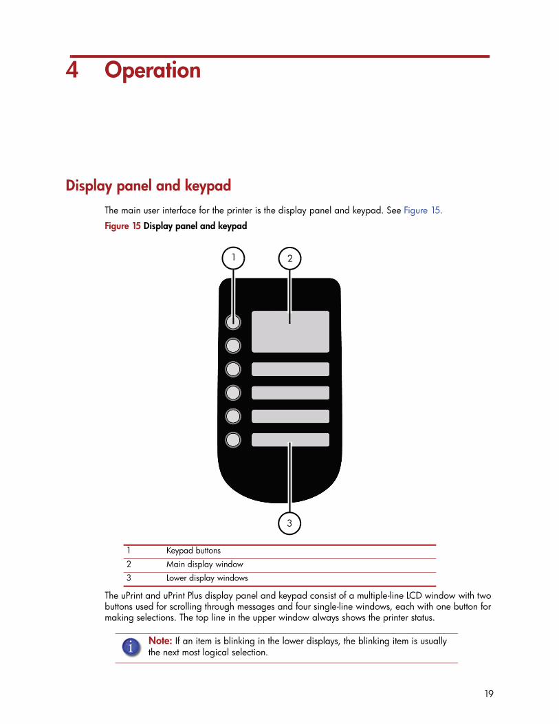
Display panel and keypadThe main user interface for the printer is the display panel and keypad. See Figure 15.
Figure 15 Display panel and keypad
The uPrint and uPrint Plus display panel and keypad consist of a multiple-line LCD window with two buttons used for scrolling through messages and four single-line windows, each with one button for making selections. The top line in the upper window always shows the printer status.
1 Keypad buttons
2 Main display window
3 Lower display windows
Note: If an item is blinking in the lower displays, the blinking item is usually the next most logical selection.
1
3
2
19

System firmware overview• Idle: If there is no part being built and no part in the build queue, the display will show that
the printer is Idle.• Wait for Part or Start Part: If the printer is in Idle and the build queue is empty, you can set it
to wait for a part. If the printer has a part in the build queue, you can press Start Part to start a build.
• Building: If the printer is building a part, you can choose to pause, set the lights either ON or OFF, view the print time or material remaining and set the printer to auto power down.
• Material: From this section you can load material, unload material or replace material.• Standby: From this section you can set the printer to Standby mode.• Maintenance: From this section you can make changes to the System, Setup or Machine.
Figure 16 Display panel hierarchy
Idle status
Material Standby Maintenance
System Setup Machine
• Set Network
• Test Parts
• Load Upgrade
• Lights Always On
• Select Language
• Gantry
• Head
• Tips
• Pause
• Lights Off
• Show Time
• Auto Power Down
• Load Material
• Unload Material
• Replace Material
Wait for Part Start Part
Building status
20
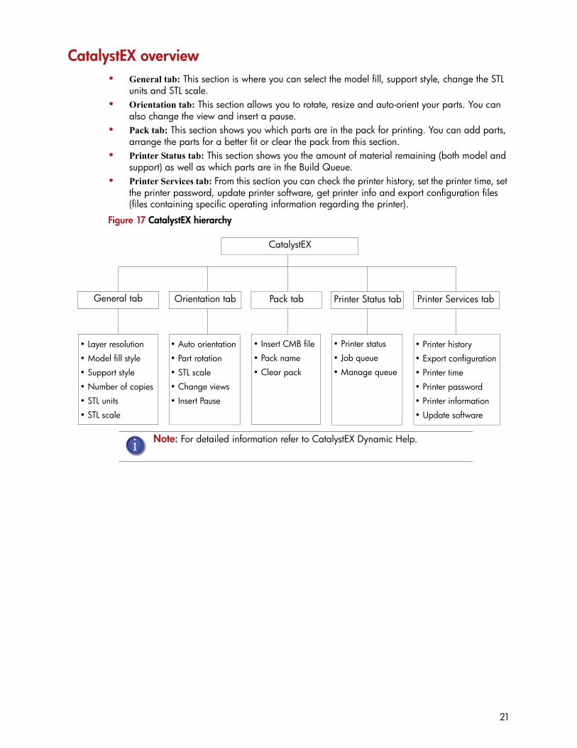
CatalystEX overview • General tab: This section is where you can select the model fill, support style, change the STL
units and STL scale.• Orientation tab: This section allows you to rotate, resize and auto-orient your parts. You can
also change the view and insert a pause.• Pack tab: This section shows you which parts are in the pack for printing. You can add parts,
arrange the parts for a better fit or clear the pack from this section.• Printer Status tab: This section shows you the amount of material remaining (both model and
support) as well as which parts are in the Build Queue. • Printer Services tab: From this section you can check the printer history, set the printer time, set
the printer password, update printer software, get printer info and export configuration files (files containing specific operating information regarding the printer).
Figure 17 CatalystEX hierarchy
Note: For detailed information refer to CatalystEX Dynamic Help.
CatalystEX
• Auto orientation
• Part rotation
• STL scale
• Change views
• Insert Pause
• Insert CMB file
• Pack name
• Clear pack
• Printer status
• Job queue
• Manage queue
• Printer history
• Export configuration
• Printer time
• Printer password
• Printer information
• Update software
• Layer resolution
• Model fill style
• Support style
• Number of copies
• STL units
• STL scale
General tab Orientation tab Pack tab Printer Status tab Printer Services tab
21

Processing your STL file for printingOpening your STL file with CatalystEX:
1. Create an STL file using your CAD software. Refer to your CAD software help section for more information about converting your CAD drawings into STL files.
2. Open the CatalystEX.
3. From the File menu select Open STL...
4. Navigate to and select the STL file that you have created.
Selecting layer resolution:
Layer resolution can be changed on the uPrint Plus printer. Changing layer resolution will affect surface finish and build times. Selecting a smaller layer resolution creates a smoother surface finish, but takes longer to build. Layer resolution also affects the minimum wall thickness. Minimum wall thickness applies to the horizontal (XY) plane of your part. If a feature in an STL is smaller than the limit, the modeler will increase the size of the feature to the minimum wall thickness.
Selecting model interior fill style:
This establishes the type of fill used for the interior areas of the part. There are three types of model interior that you can choose from.
• Solid - Used when a stronger, more durable part is desired. Build times will be longer and more material will be used.
• Sparse High Density - This is the default model interior style and is highly recommended. Build times will be shorter, less material will be used and the possibility of part curl for geometries with large mass will be greatly reduced.
• Sparse Low Density - The interior will be “honeycombed” or “hatched”. This style allows for the shortest build times and lowest material usage but will decrease the strength of the part.
Selecting support style:
Support material is used to support the model during the build process. It is removed when the part is complete. Support styles will affect the support strength and build time of the print. SMART support is the default support setting.
• Basic - May be used for most parts. Basic support uses a consistent spacing between support toolpaths.
• SMART - minimizes the amount of support material used, reduces the build time, and improves support removal for many parts. SMART supports use a wide spacing between toolpath rasters and change the shape of the support region. As the supports descend from the underside of the part feature to the base of the supports, the support region shrinks and transforms to a simpler shape to reduce the amount of material used and the build time. SMART supports are suitable for all parts, especially those with large support regions, and are the default style for builds using soluble supports
• Surround - The entire model is surrounded by support material. Typically used for tall, thin models.
Printer type Available layer resolutions Minimum Wall thickness
uPrint .010 inch (.254 mm) .036 inch (.914 mm)
uPrint Plus .010 inch (.254 mm).013 inch (.3302 mm)
.036 inch (.914 mm)
.047 inch (1.194 mm)
22

Selecting the scale of your STL file:
Before you process a part for printing, you can change the size of the part within the build envelope. Every part has a pre-defined size within the STL file. After you have opened the file you can change the size of the part produced from the STL file by changing the scale. The scale always relates to the original STL file size definition.
For example: a cube that is defined as 2 X 2 X 2 can be built to be 4 X 4 X 4 by simply changing the scale to 2.0. If after changing the scale to 2.0, you decide that a size of 3 X 3 X 3 would be preferred, change the scale to 1.5 - the scale relates to the original size of 2.0, NOT the resulting 4.0 from the first scale change.
Click within the scale input box to type a scale of your choice.
Selecting the orientation of your STL file:
The Orientation tab has an expanded preview window. It provides options for viewing a part, measuring a part, orienting a part, processing a part and viewing the layers of a part. How a part is oriented in the preview window will determine how the part is oriented when it prints.
Orientation impacts build speed, part strength, surface finish and material consumption. Orientation can also affect the ability of CatalystEX to repair any problems with the STL file.
You can choose to auto orient your part, which allows CatalystEX to determine the best orientation for the part for the fastest build time and least material usage, or you can manually change the orientation of your part.
Orientation Considerations:
• Build Speed - Closely related to material use. A lesser amount of supports will allow for a faster build speed.
Another factor affecting build speed is the axis orientation. The printer can build faster across the X-Y plane than it can along the Z axis. Orienting a part so that it is shorter within the mod-eling envelope will produce a quicker build.
• Part Strength - A model is stronger within a layer than it is across layers. Depending upon what features you want your part to demonstrate, you may need to orient your part to have its greatest strength across a specific area. For example a tab that needs to be pressed would be weakest if you are applying pressure across layers.
• Surface Finish - Much like orienting for strength, how the part is oriented will determine how the surface finish will look and allow the printer to provide the smoothest finish for a specific area. For example, if building a cylinder, orienting the cylinder upright will have a smoother surface finish than building it on its side.
• STL File Repair - It is possible for an STL file to have errors while appearing to be trouble free. If the STL file contains errors, CatalystEX may have problems processing the file. CatalystEX has the ability to automatically correct some STL file errors. How the part is oriented can impact this automated repair function.
23

Adding your STL file to the pack:
The Add to Pack button is found on the General, Orientation and Pack tabs.
When you click on the Add to Pack button, CatalystEX will add the file that is currently in the preview window (General tab or Orientation tab) to the pack preview window (Pack tab).
If the file in the preview window has not been processed for printing, processing will occur before the file is added to the pack. Each additional click of the Add to Pack button will add another copy of the file to the pack.
Printing your STL file:
The Print button is found on the General, Orientation and Pack tabs.
CatalystEX will now process all parts in the pack and create a CMB file from which the printer will print the parts.
Building a partIf a part has not been sent to your printer for building, the build queue will be empty. If the build queue is empty the display panel will show Idle or Ready to build.
Choose whether or not you want to start a build from a remote location or from the display panel at the printer.
Starting a build from a remote location:
The lower display will show Wait for Part and it will be flashing.
1. From the display panel press Wait for Part. The display will ask Is Model Base Installed?
2. Insert a modeling base.
3. Press Yes. Waiting for Part will now be on the display.
4. From your CatalystEX workstation, send a part to the printer. The printer will automatically start to build the part. See “Processing your STL file for printing” on page 22 for detailed instructions.
Starting a build from the display panel:
If Wait for Part has not been activated, you can send the part to the printer and start the part from the display panel after the part has been sent to the printer.
1. From your CatalystEX workstation, send a part to the printer. The display will show Idle/Ready to Build and the name of the first file that is in the queue waiting to be built.
2. Insert a modeling base.
3. From the display panel press Start Model to start building the part.
CAUTION: DO NOT reuse modeling bases. If a modeling base is reused, calibration errors, poor part quality, and loss of extrusion may occur. Additional modeling bases are available from your reseller.
CAUTION: DO NOT reuse modeling bases. If a modeling base is reused, calibration errors, poor part quality, and loss of extrusion may occur. Additional modeling bases are available from your reseller.
24

The display panel during buildThe top two lines of the display panel will show the printer status. See Figure 18. The bottom line of the display panel will show the amount of model and support material that remains in the carriers.
Figure 18 Display panel during build
Chamber LightsWhen a part starts to build, the chamber lights are automatically ON. The default time-out for the lights is 30 minutes. You can toggle the lights ON or OFF through the display panel.
You can set the chamber lights on permanently, however the chamber lights will return to factory settings when power is cycled.
1. From Idle or Ready to Build, on the display panel press Maintenance.
2. Press Setup.
3. Press Lights Always On.
Repeat this process to turn this option off.
Pausing a buildWhile building a part, you may want to pause the build to allow for material replacement. To pause the build at any time, from the display panel press Pause.
Resuming after pauseIf you have pressed Pause, and are ready to resume building the part, press Resume and the printer will resume printing.
Note: If a material amount is flashing, it indicates that the remaining material will not be enough to complete the current build.
Note: The printer will complete the current tool path before pausing.
Printer status
Model file name
Support material remaining
Model material remaining
Printer status
Model file nameSupport material remaining in bay 1Support material remaining in bay 2
Model material remaining in bay1Model material remaining in bay2
Single material bay
Dual material bay
25

Canceling a buildYou can cancel a build at any time while the part is building.
1. From the display panel press Pause.
2. Once the printer stops building, press Cancel Build.
3. The display will ask Are you Sure? Press Yes.
4. The display will show Build Stopped followed by the file name. You will then be prompted to remove the part and replace the modeling base.
5. Remove the part and replace the modeling base.
6. Once the chamber door has been opened and closed, the display will ask Part Removed? Press Yes ONLY after you have removed the part and replaced the modeling base.
Removing a completed partWhen the printer has completed building a part, the display will show Completed followed by the file name. It will also show Remove Part and Replace Modeling Base.
1. Open the chamber door.
2. Turn the modeling base retainers down and remove the modeling base by sliding out and pulling up.
3. Insert a new modeling base by sliding in and pushing down, turn the retainers up to lock the modeling base in place.
4. Close the chamber door.
5. After you have opened and closed the door, the display will show Part Removed? ONLY after removing the part and replacing the modeling base, from the display panel press Yes.
After you press Yes, the display will show the status as Idle or Ready to Build for the next part in the queue.
Remove a part from the modeling base:1. After removing the modeling base from the printer, firmly flex the modeling base back and
forth with your hands to loosen the part.
2. Pull the part off of the modeling base or use a putty knife to completely remove the part.
Gloves: The modeling base will be hot, wear gloves when removing the part from the printer.
CAUTION: If you press Yes before removing the part, the printer can be damaged.
Gloves: The modeling base will be hot, wear gloves when removing the part from the printer.
CAUTION: If you press Yes before removing the part, the printer can be damaged.
Note: Parts are easier to remove from the modeling base when still warm.
26

Removing support materialuPrint and uPrint Plus use soluble support material which is designed to dissolve in a soap and water based solution. Your part is left with a smooth and clean finish with the fine details intact. The soluble support material can be removed by hand with relative ease, but is designed to be dissolved from your parts for hands free finishing.
Emptying the purge bucketEmpty the purge bucket after each build to avoid part quality issues or damage to the printer.
1. With a gloved hand, lift up on the purge bucket and pull it off of the two mounts. See Figure 19.
Figure 19 Emptying the purge bucket
2. Empty the purge bucket.
3. Place the purge bucket over the two mounts and push down to lock in place.
WARNING: Support material is sharp, wear safety glasses and gloves when removing support material by hand.
Gloves: Wear gloves when emptying the purge bucket.
CAUTION: When reinstalling the purge bucket, make sure that it locks on both mounts and hangs flush with the chamber wall to avoid damage.
Purge bucket
27

Replacing material for single material bay1. From the display panel press Material... The display will show Add/Remove and
S1(remaining%) and M1(remaining%). Asterisks will mark the currently active material bays (the material bays that are currently loaded to the head).
2. Press Unload...
3. Select Unload both, Unload Model or Unload Support.
4. The printer will now unload material from the head. When the material has unloaded, you will need to replace the material carriers.
5. Open the material bay doors by gently pressing in to release and pulling outwards.
6. Remove the material carriers by first pushing them in to unlatch and then pulling them outwards.
7. Place the carrier on a flat stable surface.
8. Open the carrier.
9. Rotate the spool to rewind the material, leaving 2 inches (50mm) remaining at the material guide. See Figure 20.
Figure 20 Rewinding the material spool
10. Using a cutters, cut the excess 2 inches (50mm) of material from the material guide. leaving a blunt end.
11. Replace the material spool.
12. Close and latch the carrier.
13. Once the material carriers have been replaced press Load...
14. Select Load Model, Load Support or Load both.
15. After material has been loaded to the head press Done...
CAUTION: Do not push the material through the material guide back into the carrier, doing so can cause material to break or become tangled.
28

Replacing material for dual material bays1. From the display panel press Material... The display will show Add/Remove and
S1(remaining%), S2(remaining%) and M1, M2 (remaining%). Asterisks will mark the currently active material bays (the material bays that are currently loaded to the head).
2. Press Unload...
3. Press Unload both, Unload Model or Unload Support.
4. The printer will now unload material from the head. When the material has unloaded, you will need to replace the material carriers.
5. Open the material bay doors by gently pressing in to release and pulling outwards.
6. Remove the material carriers by first pushing them in to unlatch and then pulling them outwards.
7. Place the carrier on a flat stable surface.
8. Open the carrier.
9. Rotate the spool to rewind the material, leaving 2 inches (50mm) remaining at the material guide. See Figure 21.
Figure 21 Rewinding the material spool
10. Using a cutters, cut the excess 2 inches (50mm) of material from the material guide, leaving a blunt end.
11. Replace the material spool.
12. Close and latch the carrier.
13. Once the material carriers have been replaced press Load...
14. You can select which carriers you want to load to the head by selecting Next Model or Next Support. When done selecting press Load Selected.
15. The printer will now load the selected material bays and prepare the other bays for automatic loading. After they are done loading and preparing, press Done... the display will show Wait for Part or Ready to Build.
CAUTION: Do not push the material through the material guide back into the carrier, doing so can cause material to break or become tangled.
29

Material bay LEDsThe table below will show the status indicated by the LEDs.
Replacing material spoolsRemoving a spool of material from the carrier:
1. Place the carrier on a flat stable surface.
2. Unlatch the carrier and open.
3. Remove the spool of material. Discard any pieces of material that may remain in the carrier.
4. Remove the material guide and recycle. See “Removing the EEproms from the material guides” on page 60
5. Recycle the empty material spool. See “Recycling Codes” on page 59
6. Install a new material spool into the material carrier.
Storing material spoolsIf you will not be using the printer for more than 72 hours, unload and store model and support material in the storage bags provided to prevent moisture absorption.
1. Unload material from the printer.
2. Open the material bay doors by gently pressing in to release and pulling outwards.
3. Remove the material carriers by first pushing them in to unlatch and then pulling them outwards.
4. Place the carrier on a flat stable surface.
5. Open the carrier.
6. Rotate the spool to rewind the material, leaving 2 inches (50mm) remaining at the material guide. See Figure 22.
On Material currently loaded to the head
Off No carrier presentCarrier present and ready to be loaded
Blinking Carrier needs replacement (is empty or has an error)
CAUTION: Do not push the material through the material guide back into the carrier, doing so can cause material to break or become tangled.
30
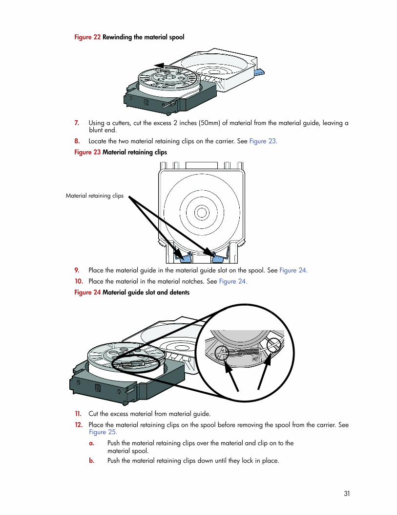
Figure 22 Rewinding the material spool
7. Using a cutters, cut the excess 2 inches (50mm) of material from the material guide, leaving a blunt end.
8. Locate the two material retaining clips on the carrier. See Figure 23.
Figure 23 Material retaining clips
9. Place the material guide in the material guide slot on the spool. See Figure 24.
10. Place the material in the material notches. See Figure 24.
Figure 24 Material guide slot and detents
11. Cut the excess material from material guide.
12. Place the material retaining clips on the spool before removing the spool from the carrier. See Figure 25.
a. Push the material retaining clips over the material and clip on to the material spool.
b. Push the material retaining clips down until they lock in place.
Material retaining clips
31

Figure 25 Installing material retaining clips
13. Remove the material spool from the material carrier. See Figure 26.
Figure 26 Properly installed material retaining clips.
14. Place the material spool in the storage bag that came with the material carrier.
Auto power downYou can set the printer to automatically power down when a build is complete. This option will save energy usage.
1. While the printer is building, press the Auto Power Down button.
2. Turn the power switch, located on the left side of the printer, to the OFF position.
The printer will display Auto Power Down Mode and the printer will power down as soon as the build is complete.
Cancelling auto power down:1. Turn the power switch back to the ON position.
Powering offTo power off the printer, turn the power switch to the OFF position. You can do this at anytime without harming the printer. No other steps are necessary. If this is done while the printer is building a part, the current part will not be completed.
Note: When not loaded in the printer, always store material spools in the material carrier or the storage bag that came with the carrier to prevent moisture absorption.
Note: System cooling fans and lights will continue to operate for several minutes after the switch has been turned off.
Place clip and push down to lock in place
32

Resuming operations from Standby modeAfter several minutes of inactivity, the printer will enter Standby mode. During Standby, the head temperature will decrease to conserve energy.
From the display panel press Resume.
Updating printer firmware:Check http://www.dimensionprinting.com/uprint/customerinfo.html for printer firmware updates. If there is an upgrade to the printer firmware, download the upgrade and install on the printer.
Installing the firmware:1. From the printer display panel, press Maintenance.
2. Press System.
3. Press Load Upgrade. The printer will then display “Send upgrade from workstation” followed by the printer’s IP address.
4. Open CatalystEX and click on the Printer Services tab.
5. Click on the Update Software button. CatalystEX will now connect to the printer and will prompt you to locate the upgrade file. Navigate CatalystEX to the directory where the upgrade file is located. The update will automatically be loaded on to the printer. After the update has been loaded, the display will show Verifying update.
6. When verification is complete, the display will show Reboot to complete. Press Yes. The printer will now reboot and return to Idle.
7. Press the Maintenance button and verify the updated version was installed correctly then exit maintenance.
33
5 Maintenance
Startup kit toolsThe startup kit contains a set of tools used to help you maintain the printer. The following is a list of the tools contained in the startup kit.
• Needle nose pliers• T-Handled allen wrench - 1/8 inch• T-Handled allen wrench - 7/64 inch• Gloves (Leather) • Cutters• Brush • Magnifier
Preventive MaintenanceDailyEmpty the purge bucket
Empty the purge bucket after each build has completed.
Inspect the tip wipe assemblyAfter each build you should inspect the tip wipe assembly to make sure there is no material build up. If there is material build up, clean the tip wipe assembly. Material build up on the tip wipe assembly can cause part quality issues. See “Tip wipe assembly” on page 35.
Inspect the tip shieldsAfter each build you should inspect the tip shields for damage or material build up. If there is material build up remove it as needed. If the material will not break free or there is damage to the tip shield, replace the tip shield. See “Tip shield replacement” on page 37.
Remove debris buildupRemove all material buildup on the Z platform and around the lead screw. Failure to do so could cause the base to not be level or the Z platform to jam at its upper limit.
Vacuum build chamberVacuum the build chamber to remove all debris and purged material.
Clean doorDo not use ammonia based glass cleaner on the door. It will damage the acrylic window.
CAUTION: ONLY use acrylic cleaner.
34
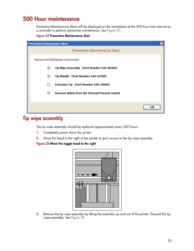
500 Hour maintenancePreventive Maintenance Alerts will be displayed on the workstation at the 500 hour time interval as a reminder to perform preventive maintenance. See Figure 27.
Figure 27 Preventive Maintenance Alert
Tip wipe assemblyThe tip wipe assembly should be replaced approximately every 500 hours.
1. Completely power down the printer.
2. Move the head to the right of the printer to gain access to the tip wipe assembly.
Figure 28 Move the toggle head to the right
3. Remove the tip wipe assembly by lifting the assembly up and out of the printer. Discard this tip wipe assembly. See Figure 29.
35

Figure 29 Replacing the tip wipe assembly
4. Place the new tip wipe assembly over the two mounting posts making sure the assembly is fully installed. See Figure 30.
Figure 30 Installing tip wipe assembly
5. Power the printer back up.
36

Tip shield replacementTip shields can become worn or damaged over time. This can have a negative impact on the surface finish and detail of models. Replace the tip shields every 500 hours.
Figure 31 Tip Shield damage
1. Enter Head Maintenance.
a. From the display panel press Maintenance.b. Press Machine. c. Press Head. The head will come to rest in the center of the chamber
and the Z platform will change position.
2. Remove the head cover by pressing the tabs in and pulling away from the head. See Figure 32.
Figure 32 Head cover tab locations
3. Position the blade of a small screwdriver between the tip shield and tip plate. Use the blade of the small screwdriver to separate the tip shield from the tip plate. See Figure 33.
Gloves: The head area is hot, wear gloves when working in this area of the printer.
New shield Worn shield
Press tabs in to remove head coverHead cover
37
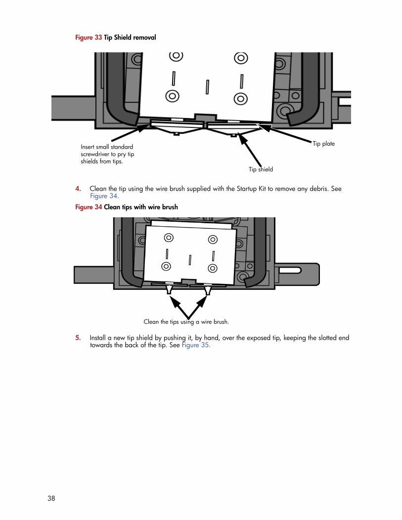
Figure 33 Tip Shield removal
4. Clean the tip using the wire brush supplied with the Startup Kit to remove any debris. See Figure 34.
Figure 34 Clean tips with wire brush
5. Install a new tip shield by pushing it, by hand, over the exposed tip, keeping the slotted end towards the back of the tip. See Figure 35.
Insert small standard screwdriver to pry tip shields from tips.
Tip shield
Tip plate
Clean the tips using a wire brush.
38

Figure 35 Tip Shield installation
6. Replace head cover.
7. Exit Maintenance, press Done until back at Idle.
Remove debris from the Filament Present switchThere may be a time when the Filament Present switch needs to be cleared in addition to the 500 hour maintenance. For example, if a Material Error-Filament blocked message appears on the display panel; the recommendation may be to clear debris from the Filament present switch.
1. Unload material from the printer and remove the material carriers.
2. Open the material bay doors by gently pressing in to release and pulling outwards.
3. Remove the material carriers by first pushing them in to unlatch and then pulling them outwards.
4. Disconnect the material tubes from the rear of the material bay(s). Leave them attached to the Y block.
5. Locate the entrance hole to the Filament Present Switch in the material bay(s). See Figure 36.
Note: If the head cover is not replaced the printer may not function properly.
39

Figure 36 Filament Present Switch location
6. Obtain a can of compressed air.
7. Insert the canned air extension tube to its spray nozzle.
8. Align the canned air extension tube with the entrance hole of the Filament Present Switch. See Figure 37.
Figure 37 Cleaning the Filament Present Switch
9. Squeeze the spray nozzle for one quick burst (approximately 2 seconds) to clear each Filament Present Switch on the model and support sides of the material bay. If an optional material bay is installed, repeat this procedure for the second bay.
10. Reconnect the material tubes to the rear of the material bay(s).
11. Replace the material carriers and load material.
Support side Filament Present Switch Model side Filament Present Switch
40

2000 Hour maintenanceTip replacement and calibration
A Preventive Maintenance Alert will be displayed after 2000 hours of run time informing you that tips need to be replaced and calibrated. See Figure 38.
Figure 38 Preventive Maintenance Alert
Removing tips:1. You will need to make sure the printer is powered ON before replacing the extrusion tips.
2. From the display panel press Maintenance.
3. Press Machine.
4. Press Tip.
5. Press Replace.
6. The printer will display Load Model - Unloading.
7. You can now open the printer door and replace the tips - or you can Cancel the tip replacement procedure.
8. Remove plastic head cover by squeezing raised pads on sides of cover. See Figure 39.
Note: Tips can also be damaged by improper care while performing maintenance in the area around the tips.
Note: CatalystEX displays the tip time (hrs) - from the Printer Services Tab - Printer Info button (Tip time will reset to zero after replacement).
41

Figure 39 Head cover tab locations
9. Remove tips
a. Use 7/64 T-Handle Allen wrench to loosen the heater block screws three to four full turns counterclockwise - or until the top of the screws are flush with the metal cover. DO NOT remove the screws entirely. See Figure 40.
Figure 40 Tip Removal
b. Use needle nose pliers to grasp the stainless steel shield of the tip. c. Pull the tip shield toward you, then pull down to remove the tip from
the heater block. Discard the used tip. See Figure 41.
Press tabs in to remove head coverHead cover
Loosen but do not remove heater block screws
Loosen but do not remove heater block screws
42

Figure 41 Remove the tips
d. Repeat for second tip if necessary.
Installing tips:1. Place the tip shield on the tip. Be sure to install the proper tip. See Figure 42.
Figure 42 Tip shield alignment
2. With gloved hand, insert the new tip into the heater block. With the slotted side towards the rear of the printer. See Figure 43.
Pull tips down to remove
Align the tip shield so the slotted end is facing the back of the printer
Slotted endSlotted end
43

Figure 43 Install the tips
3. Use needle nose pliers to grasp the stainless steel shield of the tip.
4. Pull the tip shield toward you, then lift up to install the tip.
5. Push the tip toward the back of the printer once it is all the way up against the heater block.
6. Verify the tip is fully inserted into the heater block and that the stainless steel shield is aligned. See Figure 44.
7. Use 7/64 T-Handle Allen wrench to firmly tighten the heater block clamp screws. See Figure 44.
Figure 44 Tighten heater block clamp screws.
8. Repeat steps 3 through 7 for the other tip if necessary.
Note: Make sure the tip remains all the way up against the heater block as you tighten the screws.
Tighten screwsTighten screws
44

9. Replace head cover and close the printer door.
10. The printer will display Tip Maintenance - Tips Replaced? - press Yes to begin material load.
a. The printer will display Load Model - Replace Both Carriers (flashing).
• If you want to replace a material carrier, do so now.
• If you do NOT want to change a material carrier, you must unlatch and latch the carriers to continue (Push the carrier forward to unlatch, then push it forward again to latch). Because the material ‘unloaded’ during the tip replacement, the printer is in the material replacement mode. You must unlatch and then latch the carriers to continue. If there is a delay in the unlatch/latch process, the printer will display Both Carriers Not Replaced Or Invalid. Select Retry, then unlatch and latch the carriers.
11. The printer will now begin to load material.
12. After material loading is complete the printer will display Tip Calibration - Install Modeling Base And Build Calibration Part.
Tip calibration:
Tip replacement requires Tip Calibration.
1. Select Start Part (flashing) - the printer will run two calibration parts.
• The printer will automatically build a Z Calibration part, measure the part and calibrate the Z Axis for tip depth and tip level (approximately 5 minutes). The Z calibration is automatic.
• The printer will then automatically build an XY Calibration part (approximately 10 minutes). You must inspect the XY Calibration part and calibrate the X and Y axis for tip offset:
2. When the XY Calibration part is complete the printer will display Remove Part and Select XY Adjustment - X:0, Y:0
3. Remove the XY tip calibration part from the printer.
4. Inspect the part and calibrate the X and Y axis, See Figure 45.
a. Use the magnifier from the Startup kit to view the support road (shown in red).
b. Identify the location on the +X or –X side of the part where the support road is best centered within the model boundaries (shown in blue).
c. Read the number closest to this location. This is the required X Tip Offset adjustment. If the number is on the -X side, a negative offset is required.
d. Select Increment or Decrement to input the X offset adjustment - the value will change in the upper display window (by default, the printer will be ready to accept the X value).
Note: If the head cover is not replaced the printer may not function properly.
Note: Make sure a NEW modeling base is installed before starting calibration. Calibration results will be incorrect if a NEW modeling base is not used.
45

e. When you are satisfied with your X offset value, Select Y and repeat steps A- D to identify and input the required Y Tip Offset adjustment.
Figure 45 Example XY Tip Offset Part. This example requires an adjustment of X = + 2, Y = - 4
5. Select Done after you have input the X and Y offsets. The printer will return to Maintenance. Run the XY calibration a second time to be sure the values changed the offset properly.
6. When finished, press Done until back at Idle.
46

Chamber light bar replacement1. Power down the printer.
2. Locate the wiring harness leading away from the top of the light bar.
3. Disconnect the light bar from the wiring harness by squeezing the wiring harness clip while pulling down.
4. Remove the light bar by removing the three attachment screws (top, middle, bottom) - use the 7/64 T-handle wrench supplied in the startup kit.
5. Install a replacement light bar with the three attachment screws - do not overtighten the screws.
6. Re-attach the wiring harness lead.
Figure 46 Chamber light bar locations
47

6 Troubleshooting
TroubleshootingProblem RecommendationNo power 1. Verify power cord is securely plugged in.
2. Verify that the circuit breaker (at rear of printer) and the power switch (on left side panel of printer) are both in the ON position.
3. Verify AC power is present at wall outlet.
Material not extruding Material may be clogged in tip see “Clogged tip” on page 51.
Purge material accumulating on part.
Check condition of tip wipe assembly. Replace if worn. See “Tip wipe assembly” on page 35
No text displayed on Display Panel
Cycle power. see “Cycling power” on page 50.
Cannot communicate with printer through network or crossover cable
1. Make sure network cables are connected - at the printer, at the PC, or where cables connect to network hubs.
2. Re-configure network settings.3. If using a static network address, verify that the IP address entered in CatalystEX
matches the IP address entered in the printer.4. Your network configuration may have changed. Contact your Network Adminis-
trator.
Error code displayed on display panel
Contact Technical Support. For more information, refer to“Fault determination codes” on page 49
Build Error Partial or bad part file sent to printer. Check STL file in CAD software for errors; reprocess STL in CatalystEX and re-download to printer.
Error message on display panel RecommendationCan’t Find Home – Check Modeling Base
1. Verify a modeling base is inserted.2. Modeling base may be used or defective – replace.
Material ErrorFilament error
1. Remove the carrier and verify material is coming out of the material guide.2. Verify material pulls freely from the carrier.3. Verify the material tubes are free of material.4. Reload material.
Material ErrorFilament blocked
1. Remove carrier and verify material pulls freely from carrier.2. Verify the material tubes are free of material.3. If the path is not obstructed, clean debris from Filament Present Switch. See
“Remove debris from the Filament Present switch” on page 394. Reload material.
Material ErrorCarrier invalid
1. Remove carrier and verify it is not empty.2. Replace material spool.3. Reload material.
48

Fault determination codesIf a fault occurs which would prevent the printer from executing an operator request, the printer will begin to shut down and cool. The panel will display an error code. An error-code list (with the filename “error.txt”) can be found on the DVD-ROM for the printer firmware. (Because this list may change with each new software version, be sure to check the error.txt attachment when you install new firmware upgrades.)
After the printer has finished cooling, the only option displayed is Continue. Press Continue and the printer will reboot and try to return to normal operation. If pressing Continue does not eliminate the error, power should be cycled (see “Cycling power” on page 50.); wait 60 seconds before switching power on again. In most cases you will be able to continue operation. However, if the printer continues to shut down and display the same error, contact technical support.
Exporting printer configuration (.cfg) fileIf your printer is receiving fault determination codes, you may need to export a configuration (.cfg) file from your printer to send to Customer Support.
Exporting configuration file from printer:1. Open CatalystEX from your workstation.
2. Click on the Printer Services tab.
3. Click on the Export Configuration button.
4. Browse to the directory where you wish to save the configuration file.
5. Click on the Save button.
6. Close CatalystEX.
Material ErrorFilament broken
1. Remove the carrier and verify material is coming out of the material guide.2. Verify material pulls freely from the carrier.3. Verify the material tubes are free of material.4. Reload material.
Load ErrorFilament blocked
1. Remove the carrier and verify material is coming out of the material guide.2. Verify the material pulls freely from the carrier.3. Verify the material tubes are free of material.4. If the path is not obstructed, clean debris from Filament Present Switch. See
“Remove debris from the Filament Present switch” on page 395. Reload material.
Load ErrorPurge failed
1. Remove the carrier and verify material is coming out of the material guide.2. Verify the material pulls freely from the carrier.3. Verify the material tubes are free of material.4. Check for and clear any excess material build up around the tips.
Unload ErrorUnload failed
Remove the carrier and verify the material tubes are free of material.
Model/Support Jamin headclear before resuming
See “Material Jam” on page 6-52.
Pausing 1. Press Resume.2. Unload the material carriers and reinstall.
Note: Certain Filament related error messages will allow you to enter maintenance mode after a 30 second timeout.
Error message on display panel Recommendation
49

Cycling power1. Turn the power switch to the OFF position. The display will show Shutting Down.
2. After the printer has cooled down enough to shut down, the display will go blank.
3. When the display is blank and the printer has shut down, turn the circuit breaker to the OFF position.
4. Once the circuit breaker has been turned to the OFF position, wait 60 seconds and turn the circuit breaker back to the ON position.
5. Turn the power switch to the ON position. The printer display will show that it is starting up.
Once the display shows Idle or Ready to Print, you can send a file to the printer to be printed.
Diagnosing loss of extrusionOccasionally, the printer’s head may experience loss of extrusion. This will be evident by observing one of the following:
• The head is moving with no material coming out of either tip• The height of the model and support materials are not equal• Sagging structures due to lack of support materials
1. From the display panel press Cancel and remove parts from the printer.
2. Insert a new modeling base.
3. From Idle, press Maintenance
4. Press Machine.
5. Press Head. The head will move to the center of the chamber and the Z platform will change position. The display will read: Model Drive Motor Stopped
6. Determine if there is a model material extrusion problem by pressing Forward (command will be available after head reaches operating temperature). Watch the model tip (right tip) for any extrusion (material purge).
7. Press Stop to stop the extrusion.
8. If material did NOT flow from the model tip, see “Recovering from loss of extrusion” on page 54. If material steadily flowed from the model tip, the model tip is functioning properly.
9. Test the support material tip by choosing: Select Drive.
10. Determine if there is a support material extrusion problem by pressing Forward. Watch the support tip (left tip) for any extrusion (material purge).
11. Press Stop to stop the extrusion.
12. If material did NOT flow from the support tip, see “Recovering from loss of extrusion” on page 54. If material steadily flowed from the support tip, the support tip is functioning properly.
13. Return the printer to the Maintenance state - Press Done, then press Yes when the printer displays Is Material Loaded?
14. Press Done until back at Idle.
Gloves: The head area is hot. Use gloves when working in this area of printer.
Note: You may need to wait up to 30 seconds before extrusion will begin as the tip may need to reach operating temperature
50

Clogged tipOccasionally, a tip may clog with material. This will often result in a loss of extrusion (LOE). A clogged tip will prohibit material load and part building.
1. Remove the head cover by pressing the tabs in and pulling away from the head. See Figure 47.
Figure 47 Remove the head cover
2. Inspect to of tips for material build up. If there is excess material build up see “Recovering from loss of extrusion” on page 54. If there is no excess material build up close the chamber door and continue.
3. From the display panel press Maintenance.
4. Press Machine. The printer will calibrate which will take approximately 3 minutes.
5. Press Head. The head will heat up to operating temperature which will take approximately 3 minutes.
6. Press Select Drive and choose the drive that may have the clogged tip.
7. Press Forward, the drive wheel will turn the selected drive forward.
8. Press Blower Off, this will turn the head cooling fan off for 10 seconds, allowing the tip to heat up beyond operating temperature. If material starts to extrude the tip is no longer clogged. If material does not extrude see “Recovering from loss of extrusion” on page 54
9. Press Done.
10. Replace head cover.
11. Display will ask Which Materials Loaded? Press Both.
12. Press Done until back to Idle.
Gloves: The head area is hot. Use leather gloves when working in this area of printer.
Note: If the head cover is not replaced the printer may not function properly.
Press tabs in to remove head coverHead Cover
51

Material JamOccasionally, material may become jammed in the head. The printer will notify you of a material jam through a message shown on the display panel. If a material jam is detected, follow these steps to clear the jam.
1. From the display panel, press Continue.
2. Press Maintenance.
3. Press Machine.
4. Press Head.
5. Once in head maintenance mode, remove the head cover by pressing the tabs in and pulling away from the head. See Figure 48.
Figure 48 Remove the head cover
6. Inspect tip inlets for material build up see Figure 49. If there is excess material build up see “Recovering from loss of extrusion” on page 54. If there is no excess material build up close the chamber door and continue.
Gloves: The head area is hot. Use leather gloves when working in this area of printer.
Press tabs in to remove head coverHead Cover
52

Figure 49 Tip inlet locations
7. Press Select Drive and choose the drive that may have the clogged tip.
8. Press Forward, the drive wheel will turn the selected drive forward.
9. Press Blower Off, this will turn the head cooling fan off for 10 seconds, allowing the tip to heat up beyond operating temperature. If material starts to extrude the tip is no longer clogged. If material does not extrude see “Recovering from loss of extrusion” on page 54. If material extrudes, you can continue building your part.
10. Reinstall the head cover.
11. Press Done.
12. Display will ask Which Materials Loaded? Press Both.
13. Press Done until back to Pause screen.
14. Press Resume to continue building the part.
Note: If the head cover is not replaced the printer may not function properly.
Model tip inletSupport tip inlet
53

Recovering from loss of extrusion
1. Enter Head Maintenance mode.
a. From Idle, press Maintenance.b. Press Machine.c. Press Head. The head will heat up to operating temperature which
will take approximately 3 minutes.
2. Remove the head cover by pressing the tabs in and pulling away from the head. See Figure 50.
Figure 50 Remove the head cover
3. Place the toggle bar in neutral position (bar will extend equally from both sides of head). This can be done manually - push on the extended bar end. See Figure 51.
Note: It is recommended that you read and understand this entire procedure before performing any of the work.
Gloves: The head area is hot. Use leather gloves when working in this area of printer.
Press tabs in to remove head coverHead Cover
54

Figure 51 Head Components
Figure 52 Toggle bar in neutral position
4. Remove any excess material found around the head area.
a. Clean out as much of the material as possible using needle nose pliers, a probe, or equivalent tool.
Note: Material fed to the tip can sometimes jam causing a build-up of material under the head cover.
CAUTION: The end of the tip where the material enters is called the extrusion tube. Extrusion tubes are fragile. Use care when working in this area so as to avoid damage to the tubes.
Support side idler wheel
Model side idler wheel
Toggle spring
Heater block
Drive wheelToggle bar
55

b. For easier access to areas that may need to be cleaned, move the material idler wheels out of the way (there is one idler wheel for support material and one for model material, see Figure 51.)
i. Place a 7/64 T-Handle Allen wrench between the toggle spring post and the idler wheel post as illustrated in Figure 53. (model side shown).
ii. Position toggle bar to the same side of the head as the T-Handle allen wrench. See Figure 53. (model side shown).
Figure 53 Create access space for cleaning - model side shown
iii. Move idler wheel assembly by pushing with 7/64 inch T-Handle Allen wrench against spring tension. Insert a 1/8 T-handled Allen wrench (from startup kit) into the fixture hole. See Figure 54.
Note: Move only one idler wheel assembly at a time. Finish cleaning around the moved wheel and restore it to its normal position before moving the other idler wheel. Having both wheels out of position simultaneously could stretch the spring.
Position toggle bar to same side of head as T-Handle.
Idler wheel post
Toggle spring post
56

Figure 54 Holding access space open - model side shown
iv. Ease pressure on the 7/64 T-Handle Allen wrench to carefully return the leveraged idler wheel back toward its original position - until the idler assembly is resting against the 1/8 T-Handle Allen wrench.
v. Remove the 7/64 T-Handle Allen wrench.c. Cut the material above the idler wheel using a cutters.d. Clean the area that is now accessible using a needle nose pliers, a
probe or equivalent tool.
e. Reposition the 7/64 T-Handle Allen wrench between the toggle spring post and the idler wheel post.
f. Move idler wheel assembly by pushing with 7/64 inch T-Handle Allen wrench against spring tension and remove the 1/8 T-handled Allen wrench.
g. Remove the 7/64 T-Handle Allen wrench.
5. Repeat for the opposite side as needed.
6. Replace the head cover.
7. Press Done on the display panel.
8. Display will ask Which Materials Loaded? Press Model if only model material is loaded, press Support if only support material is loaded or press Both if both model and support material are still loaded. Press None if neither are loaded.
9. Display will ask you to remove the carrier of the materials that are not loaded. Remove the carrier and cut the excess material.
10. Press Done until back at Idle.
11. Reload the material that is not loaded.
Note: Make sure that all loose material is removed from the affected area.
Note: If the head cover is not replaced the printer may not function properly.
Insert 1/8 inch T-Handle into fixture hole.
57

58
7 Support
RegistrationTo register your uPrint or uPrint Plus 3D printer, visit http://www.dimensionprinting.com/uprint/customerinfo.html
Customer SupportVisit http://www.dimensionprinting.com/uprint/customerinfo.html for the following:
• How to order consumable parts for your uPrint or uPrint Plus printer.• Technical support contact information for your uPrint or uPrint Plus printer.• Technical support for your SST tank.• Part finishing information.
When contacting technical support please provide the following:
By phone:
• System model.• System serial number.• System software build number.• CatalystEX version number.• Detailed description of the problem you are experiencing.• Please try to be near the printer for troubleshooting, if possible.
By email:
• System model.• System serial number.• Your name.• Your telephone number.• Detailed description of the problem you are experiencing.
For advanced troubleshooting (provide by email):
• System CFG file.• STL and/or CMB files.• Detailed photographs showing the issue.

8 Recycling
Recycle all materials per your local recycling guidelines.
Figure 55 Recycling Codes
Follow your local recycling guidelines when recycling electronic components.
System Component Materials Recycling Code
X (2) and Y (4) guide rod restraints (orange) ABS
Model material guide (red, both halves) ABS
Support material guide (black, both halves) ACETAL
Material retaining clip (blue) ABS
Material Carrier (clear top, black bottom and bottom cover. Latches, hinge pin and electronics not included)
PC
Material Spool & lid (gray) PS - HI
Modeling bases ABS
EEproms Electronics
Desiccants can be recycled per your local recycling guidelines
All packaging materials can be recycled per your local recycling guidelines.
59

Removing the EEproms from the material guides1. Open the model and support material carriers and remove the material guides.
2. With a small standard screwdriver, pry the two material guide halves apart. See Figure 56.
Figure 56 Pry the model material guide apart
3. Recycle the EEPROM per your local electronics recycling guidelines.
4. Recycle the material guides per your local guidelines. See Figure 55.
Removing the desiccant from the material spool1. Remove the excess material from the material spool.
2. Use a standard screwdriver to pry the desiccant cover open. See Figure 57.
Figure 57 Removing the desiccant
3. Remove the desiccant and recycle per your local guidelines.
4. Recycle the material spool per your local guidelines.
Pry apart with a small standard screwdriver
Pry apart with a standard screwdriver
Remove the desiccant and recycle. Recycle the material spool.
60
9 Printer Specifications
The information in this section is applicable to both uPrint and uPrint Plus printers.
Physical specifications
Facility specifications
Height 762 mm (30 in)
Width 660 mm (26 in)
Depth 660 mm (26 in)
Weight 59 kg (130 lbs)
Material bay height 153 mm (6 in)
Material bay width 660 mm (26 in)
Material bay depth 660 mm (26 in)
Material bay weight 17 kg (17 lbs)
Installation location Stable flat surface capable of holding 100 kg (220 lbs), with a height clearance of 90 - 100 cm (36 - 40 in).Note - if using additional material bay:Stable flat surface capable of holding 120 kg (260 lbs), with a height clearnace of 117 - 127 cm (46 - 50 in).
Power Requirements 100–240VAC ~ 12 - 7A 50/60Hz 1200W dedicated circuit within 2 m (80 in.)Do not use an extension cord or a power strip, using these can possibly cause intermittent power issues.)
Air Circulation 115 mm (4.5 in) minimum space behind printer for air circulation.153 mm (6 in) minimum space around printer for air circulation.
Network Connection Ethernet 10/100 Base T within 4m (14 ft).
61

Workstation specifications
Power specifications
Environmental specifications
Acoustic specifications
Operating System Microsoft Windows XP, Microsoft Windows Vista or Microsoft Windows 7
Processor Minimum: 2.4 GHzFaster processors will shorten job processing times
RAM Minimum: 1GB (2GB for Windows Vista or Windows 7)Recommended: 2GB (3GB for Windows Vista or Windows 7)
Hard Disk Installation: 90MB
Monitor graphics reso-lution
Minimum: 1024x768Recommended: 1280x1024 (wide screen acceptable)
Video Card Required: OpenGL compliant accelerated graphics cardRecommended: Hardware support for OpenGLRecommended 128MB graphics card memory
Source (nominal) 100–240VAC ~ 12 - 7A 50/60Hz 1200WDo not use an extension cord or a power strip, using these can possibly cause intermittent power issues.
Temperature range . 15◦C to 30◦C (59◦F to 86◦F)
Relative humidity range 30 to 70 percent, non condensing
Heat emission 2550 BTU/hr typical
Idle sound pressure at bystander 55 dBA
Operating sound pressure at bystander
62 dBA
62

10 Supplemental Information
Stratasys Limited Warranty Statement
Stratasys, Inc. ("Stratasys") warrants its' uPrint® and uPrint® Plus 3D systems and associated peripheral devices and replacement parts (collectively, the "Product") purchased from Stratasys or an Authorized Stratasys Reseller to be free from defects in material and workmanship according to the terms and conditions stated below:
Warranties extend only to the original purchaser of the Product. The warranty on the original Product, as delivered, extends for one year starting on the date of delivery. Your sole remedy as purchaser under this Limited Warranty shall be repair or replacement as provided herein.
To preserve your warranty rights, all uPrint® and uPrint® Plus Products must be installed in accordance with the then-current User Guide available at www.uPrintDimension.com. During the Limited Warranty period, Stratasys or its' designated representative will, at their option, repair or replace a defective Product as set forth below. Service Parts and replacement Products will be furnished on an exchange basis, and will be either new or refurbished. All replaced parts or replaced Products become the property of Stratasys, and you will be invoiced for replacement parts if defective parts are not returned as directed by Stratasys under this Limited Warranty.
Stratasys will bear the cost of returned parts, as well as for shipping new or rebuilt replacement parts to you, provided that you report the warranty claim within the Limited Warranty period and obtain return instructions from Stratasys prior to return. Replacement parts independently carry a 90-day warranty from date of shipment from Stratasys or designated representative location. Consumable parts are not covered by this Limited Warranty. Warranty services may be provided by Stratasys, an Authorized Reseller, or a third party service provider designated by Stratasys.
No coverage or benefits under this Limited Warranty will exist if any of the following conditions apply:
(a)The uPrint® and uPrint® Plus Product has been subjected to abnormal use, improper or inadequate maintenance, unauthorized modifications, unauthorized repair, misuse, abuse, exposure to moisture, flooding, fire, electrical problems associated with incoming power, or other acts which are not the fault of Stratasys, Inc.
(b)Stratasys' Customer Service Department was not notified of the defect or malfunction of the uPrint® and uPrint® Plus system prior to expiration of the one year warranty period.
(c)Parts or consumables were installed and used that were not certified or approved by Stratasys.
Stratasys will also not be liable under any circumstances for Product replacement or associated labor, loss of use, loss of profits, or for any other indirect, incidental, collateral, exemplary, punitive, consequential or special damages, or losses arising out of the purchase of uPrint® and uPrint® Plus Products and/or out of this limited warranty, even if Stratasys or its' designated representative have been advised of the possibility of such damages or claims. To the extent such claims are not excludable as adjudged by a court of competent jurisdiction, you agree to accept as sole and exclusive remedy, a payment equal to the original purchase price for the product adjudged to be defective.
63

SOME COUNTRIES, REGIONS, STATES OR PROVINCES DO NOT ALLOW THE EXCLUSION OR LIMITATION OF REMEDIES OR OF INCIDENTAL, PUNITIVE, OR CONSEQUENTIAL DAMAGES, OR THE APPLICABLE TIME PERIODS, SO THE ABOVE LIMITATIONS OR EXCLUSIONS MAY NOT APPLY TO YOU. EXCEPT TO THE EXTENT LAWFULLY PERMITTED, THIS LIMITED WARRANTY DOES NOT EXCLUDE, RESTRICT OR MODIFY, AND IS IN ADDITION TO THE STATUTORY RIGHTS APPLICABLE TO THE SALE OF THIS PRODUCT TO YOU.
This warranty gives you specific legal rights and you might also have other rights that vary from country/region to country/region, state to state, or province to province.
EXCEPT FOR THIS LIMITED WARRANTY, AND TO THE FULLEST EXTENT ALLOWED BY LAW, NEITHER STRATASYS NOR ANY AUTHORIZED RESELLER MAKES ANY OTHER WARRANTY OF ANY KIND, EXPRESS OR IMPLIED, INCLUDING ANY IMPLIED WARRANTY OF MERCHANTABILITY OR FITNESS FOR A PARTICULAR PURPOSE. STRATASYS DOES NOT OFFER, ASSUME OR AUTHORIZE THE OFFER OR ASSUMPTION OF LIABILITY FOR IT OR FOR ANY OTHER WARRANTY, EITHER EXPRESS OR IMPLIED BY ANY AUTHORIZED RESELLER OR OTHER INDEPENDENT THIRD PARTY.
64

Declaration of Conformity
Stratasys, Inc. 7665 Commerce Way, Eden Prairie, MN 55344-2080 U.S.A. Main: 952.937.3000 Fax: 952.906.0070 www.stratasys.com
108480-0002
Declaration of Conformity Manufacturer Stratasys Inc.
7665 Commerce Way Eden Prairie, MN 55344-2080
EU Representative Tim B. Heller
Type of Equipment: 3D Printer
Model Numbers: 180-00108, uPrint 3D Printer 180-00109, uPrint 3D Printer 180-00110, uPrint 3D Printer 180-50001, uPrint Plus 3D Printer
We declare under our sole responsibility that the devices mentioned above comply with the following EU Directives:
Electromagnetic Compatibility (EMC)
Low Voltage
89/336/EEC
2006/95/EC
Common Technical Specifications used for demonstration of compliance:
EN55022:1998 EN 6100-3-2: 2003 EN55024:1998 EN 6100-3-3: 1995 EN60950-1: 2006
Date of Validity: December 29, 2009
Design and Technical Construction file maintained at:
Stratasys Inc. 7665 Commerce Way Eden Prairie, MN 5534-20804
Stratasys GmbH Weismüllerstr. 2760314 Frankfurt am MainGermanyTel +49 69 420 9943 0
Name of Authorized Signatory:
Position Held in Company:
S.Scott Crump
Chief Executive Officer
Tim B. Heller
Managing Director, Europe
Signatures:
65

Regulatory and environmental informationEMC Class A Warning
FCC Statements (U.S.A.)
The U.S. Federal Communications Commission (in 47 cfr1 5.105) has specified that the following notices be brought to the attention of users of this product.
This device complies with part 15 of the FCC rules. Operation is subject to the following two conditions:(1) this device may not cause harmful interference, and (2) this device must accept any interference received, including interference that may cause undesired operation.
Shielded cables: use of shielded data cables is required to comply with the Class A limits of Part 15 of the FCC Rules.
Caution: Pursuant to Part 15.21 of the FCC Rules, any changes or modifications to this equipment not expressly approved by the Hewlett-Packard Company may cause harmful interference and void the FCC authorization to operate this equipment.
Note: This equipment has been tested and found to comply with the limits for a Class A digital device, pursuant to Part 15 of the FCC Rules. These limits are designed to provide reasonable protection against harmful interference in a commercial environment. This equipment generates, uses and can radiate radio frequency energy and, if not installed and used in accordance with the instructions, may cause harmful interference to radio communications. Operation of this equipment in a residential area is likely to cause harmful interference, in which case the user will be required to correct the interference at their own expense.
Canada Electromagnetic compatibility (EMC)
Normes de sécurité (Canada)
Le présent appareil numérique n’émet pas de bruits radioélectriques dépassant les limites applicables aux appareils numériques de Classe A prescrites dans le réglement sur le brouillage radioélectrique édicté par le Ministère des Communications du Canada.
DOC statement (Canada)
This digital apparatus does not exceed the Class A limits for radio noise emissions from digital apparatus set out in the Radio Interference Regulations of the Canadian Department of Communications.
MSDS (Material Safety Data Sheet)
You can obtain current Material Safety Data Sheets for the material used in the printer by visiting http://www.dimensionprinting.com
WARNING: This is a Class A product. In a domestic environment this product may cause radio interference in which case the user may be required to take adequate measures.
66

Disposal of waste equipment by users in private households in the European Union
This symbol on the product or on its packaging indicates that this product must not be disposed of with your other household waste. Instead, it is your responsibility to dispose of your waste equipment by handing it over to a designated collection point for the recycling of waste electrical and electronic equipment. The separate collection and recycling of your waste equipment at the time of disposal will help to conserve natural resources and ensure that it is recycled in a manner that protects human health and the environment. For more information about where you can drop off your waste equipment for recycling, please contact your local city office, your household waste disposal service or the shop where you purchased the product.
67

11 Appendix
Uninterruptible Power Supply (UPS) Use and Installation
The intent of the Uninterruptible Power Supply (UPS) shutdown feature on Dimension and uPrint 3D printers is to prevent required maintenance and/or system damage by safely shutting the system down in the event of an uncontrolled loss of power. Whether an in-process build of a part will complete successfully is dependent on the battery life of the selected UPS and the duration of the power outage.
The user should select a UPS with the following specifications:
• Runtime minimum of 15 minutes at 1000W output (run times >15 minutes may be appropriate based on the typical duration of power outages at the site)
• Peak output (minimum) of 1500W• Dry contact (voltage free) interface for “On battery” and “Low battery” conditions• Dry contact interface capable of carrying at least 100mA at 12VDC.
The Installation Instructions below are specifically for connecting the I/O portion of an American Power Conversion Corporation (APCC) Smart-UPS 2200VA module to Dimension and uPrint 3D printers. Similar instructions should be followed if alternative manufacturer and/or models that meet the above specifications are selected.
Model Numbers and Options
In addition to the UPS, the Relay I/O SmartSlot Card is required to enable electrical interface from the UPS to the 3D printer.
APCC Smart-UPS 2200VA
• 120V (part number SUA2200)• 208V (part number SUA3000XLT)• 230V (part number SUA2200I)
Relay I/O SmartSlot Card (part number AP9610)
General Information
Refer to the UPS and I/O Module Installation and Operation Guides for instructions on installing the I/O module into the UPS unit as well as for connecting AC power to the UPS and 3D printer. While connecting the 3D printer power to the UPS will provide some protection against power outages, the 3D printer will shut down safely when “on battery” and “low battery” conditions are detected. Follow the Electrical Interface Connection information below.
A1

Electrical Interface Connection1. Using the cable diagram and parts list below, build an appropriate length UPS to 3D printer
cable;
2. Connect the cable from the UPS unit’s I/O Module (25-pin DSub) connector to the UPS (9-pin DSub) connector on the rear of the 3D printer.
3. Follow the instructions in the UPS Installation and Operation Guide to set the “Low Battery Warning Level” to 8 minutes.
Parts List – Cable, UPS to 3D Printer
References1. APCC Smart-UPS Installation and Operation Guide
2. APCC Relay I/O Module User’s Guide
Note: Make certain to install the jackscrews that hold the cable connectors to their respective mates (do not over-tighten)
Note: The default value of 2 minutes may not provide adequate time to ensure the 3D printer can shut down safely.
Item Qty Nomenclature / Description Material Specification
1 1 Conn, Hsg, Plug, 9PosS AMP - 205204-1
2 1 Conn, Hsg, Plug, 25Pos AMP - 205208-1
3 6 Pin, Male, 24-20 AWG AMP - 1-66506-0 or 66506-4
4 1 Shell, Size 1, 9-Pin w/Grommets AMP - 748677-1
5 1 Shell, Size 3, 25-Pin w/Grommets AMP - 748677-3
6 2 Jackscrew Pair 4-40, Knurled AMP - 747784-3
7 1 XX (length needed)Cable, 2 Conductor, 22 AWG ALPHA - 1172C or Equivalent
8 1 4.5 inch (115 mm) Sleeving, Heatshrink 1/4 Inch (7 mm) 3M - FP301 or Equivalent
9 1 Conn, Hsg, Plug, 9Pos-Solder Cup AMP - 747904-4
10 1 Conn, Hsg, Plug, 25 Pos-Solder Cup AMP - 747912-4
A2

Figure 58 UPS Cable diagram
A3
Related Documents