UPRIGHT RAMMER WITH 4 HP ROBIN ® ENGINE 96422 SET UP, OPERATING, AND SERVICING INSTRUCTIONS Using an engine indoors CAN KILL YOU IN MINUTES. Engine exhaust contains carbon monoxide. This is a poison you cannot see or smell. NEVER use inside a home or garage, EVEN IF doors and windows are open. Only use OUTSIDE and far away from windows, doors, and vents. Visit our website at: http://www.harborfreight.com Read this material before using this product. Failure to do so can result in serious injury. SAVE THIS MANUAL. Copyright © 2007 by Harbor Freight Tools ® . All rights reserved. No portion of this manual or any artwork contained herein may be reproduced in any shape or form without the express written consent of Harbor Freight Tools. Diagrams within this manual may not be drawn proportionally. Due to continuing improvements, actual product may differ slightly from the product described herein. Tools required for assembly and service may not be included. For technical questions or replacement parts, please call 1-800-444-3353. Revised Manual 09c, 09k

Welcome message from author
This document is posted to help you gain knowledge. Please leave a comment to let me know what you think about it! Share it to your friends and learn new things together.
Transcript
UPRIGHT RAMMER wITH 4 HP ROBIN® ENGINE
96422SET UP, OPERATING, ANd SERvIcING
INSTRUcTIONS
Using an engine indoors cAN KILL YOU IN MINUTES.Engine exhaust contains carbon monoxide. This is a poison you cannot see or smell.
NEvER use inside a home or garage, EvEN IF doors and windows are open.
Only use OUTSIdE and far away from windows, doors, and vents.
visit our website at: http://www.harborfreight.com
Read this material before using this product. Failure to do so can result in serious injury. SAvE THIS MANUAL.
Copyright© 2007 by Harbor Freight Tools®. All rights reserved. No portion of this manual or any artwork contained herein may be reproduced in any shape or form without the express written consent of Harbor Freight Tools. Diagrams within this manual may not be drawn proportionally. Due to continuing improvements, actual product may differ slightly from the product described herein. Tools required for assembly and service may not be included.
For technical questions or replacement parts, please call 1-800-444-3353.Revised Manual 09c, 09k

Page 2SKU 96422 For technical questions, please call 1-800-444-3353.
cONTENTSIMPORTANT SAFETY
INFORMATION ........................... 3GENERAL SAFETY RULES ............. 3SPEcIFIc SAFETY RULES .............. 5
SPEcIFIcATIONS ......................... 6
UNPAcKING ................................. 6
OPERATING INSTRUcTIONS ..... 6TO TRANSPORT THE RAMMER ..... 6PRE-START INSTRUcTIONS ........... 6TO START THE ENGINE .................. 7MAcHINE OPERATION .................... 8
MAINTENANcE ANd SERvIcING ................................ 9
cLEANING, MAINTENANcE, ANd LUBRIcATION ................................ 9
TROUBLESHOOTING ..................... 10
PARTS LIST - ENGINE & FRAME ..................11
ASSEMBLY dIAGRAM - ENGINE & FRAME ................. 12
PARTS LIST - dRIvE TRANSMISSION ........ 13
ASSEMBLY dIAGRAM - dRIvE TRANSMISSION ........ 14
PARTS LIST - PISTON ASSEMBLY .............. 15
ASSEMBLY dIAGRAM - PISTON ASSEMBLY .............. 16
PARTS LIST - SUPPORT PLATE .................. 17
LIMITEd 90 dAY wARRANTY ... 18

Page 3SKU 96422 For technical questions, please call 1-800-444-3353.
SAvE THIS MANUALKeep this manual for the safety warn-
ings and precautions, assembly, operat-ing, inspection, maintenance and cleaning procedures. Write the product’s serial number in the back of the manual near the assembly diagram (or month and year of purchase if product has no number). Keep this manual and the receipt in a safe and dry place for future reference.
IMPORTANT SAFETY INFORMATION
In this manual, on the labeling, and all other information provided with this product:
This is the safety alert symbol. It is used to alert you to potential personal injury hazards. Obey all safety messages that follow this symbol to avoid possible injury or death.
dANGER indicates a hazardous
situation which, if not avoided, will result in death or serious injury.
wARNING indicates a
hazardous situation which, if not avoided, could result in death or serious injury.
cAUTION, used with the safety
alert symbol, indicates a hazardous situation which, if not avoided, could result in minor or moderate injury.
NOTIcE is used to address practices
not related to personal injury.
cAUTION, without the safety alert
symbol, is used to address practices not related to personal injury.
wARNING! Read all instructions. Failure to follow all instructions listed below may result in fire, serious injury and/or dEATH. The warnings and precautions discussed in this manual cannot cover all possible conditions and situations that may occur. It must be understood by the operator that common sense and caution are factors which cannot be built into this product, but must be supplied by the operator.
SAvE THESE INSTRUcTIONS
GENERAL SAFETY RULES wARNING! Read all instructions Failure to follow all instructions listed below may result in serious injury.
work area safety1. Keep work area clean and well a. lit. Cluttered or dark areas invite accidents.Do not operate power tools in b. explosive atmospheres, such as in the presence of flammable liquids, gases or dust. Power tools create sparks which may ignite the dust or fumes.Keep children and bystanders c. away while operating a power tool.

Page 4SKU 96422 For technical questions, please call 1-800-444-3353.
Distractions can cause you to lose control.
Personal safety2. Stay alert, watch what you are a. doing and use common sense when operating a power tool. Do not use a power tool while you are tired or under the influence of drugs, alcohol or medication. A moment of inattention while operating power tools may result in serious personal injury.Use safety equipment. Always wear b. eye protection. Safety equipment such as dust mask, non-skid safety shoes, hard hat, or hearing protection used for appropriate conditions will reduce personal injuries.Avoid accidental starting. Ensure c. the switch is in the off-position when the unit is not in use. Carrying power tools with your finger on the switch or plugging in power tools that have the switch on invites accidents.Remove any adjusting key or wrench d. before turning the power tool on. A wrench or a key left attached to a rotating part of the power tool may result in personal injury.Do not overreach. Keep proper e. footing and balance at all times. This enables better control of the power tool in unexpected situations.Dress properly. Do not wear loose f. clothing or jewelry. Keep your hair, clothing and gloves away from moving parts. Loose clothes, jewelry or long hair can be caught in moving parts.
Power tool use and care4. Do not force the power tool. Use a. the correct power tool for your application. The correct power tool will do the job better and safer at the rate for which it was designed.Do not use the power tool if the b. switch does not turn it on and off. Any power tool that cannot be controlled with the switch is dangerous and must be repaired.Store idle power tools out of the c. reach of children and do not allow persons unfamiliar with the power tool or these instructions to operate the power tool. Power tools are dangerous in the hands of untrained users.Maintain power tools. Check for d. misalignment or binding of moving parts, breakage of parts and any other condition that may affect the power tools operation. If damaged, have the power tool repaired before use. Many accidents are caused by poorly maintained power tools.Use the power tool in accordance e. with these instructions and in the manner intended for the particular type of power tool, taking into account the working conditions and the work to be performed. Use of the power tool for operations different from those intended could result in a hazardous situation.
Service5. Have your power tool serviced by a. a qualified repair person using only identical replacement parts. This will ensure that the safety of the power tool is maintained.

Page 5SKU 96422 For technical questions, please call 1-800-444-3353.
SPEcIFIc SAFETY RULESUsing an engine indoors CAN KILL 1. YOU IN MINUTES. Engine exhaust contains carbon monoxide. This is a poison you cannot see or smell. NEVER use inside a home or garage, EVEN IF doors and windows are open. Only use OUTSIDE and far away from windows, doors, and vents.
Fire and explosion Hazard! Do not 2. fill while engine running or hot, while smoking, or if damaged. Do not overfill.
Hold securely with both hands on 3. proper handle locations. Creates strong forces during operation. Pregnant women or infirm persons should consult physician before use.
Keep children away during use. 4. Store out of reach of children with engine switch and fuel lever turned off.
5. Wear steel-toed work boots, ANSI-approved safety goggles, dust mask, ear protection, and heavy-
duty work gloves during use.
Keep out from under base.6.
Move carefully and securely in upright 7. position. Refer to manual for details. Rammer extremely top heavy.
Maintain labels and nameplates on 8. the tool. These carry important safety information. If unreadable or missing, contact Harbor Freight Tools for a replacement.
The Spring Retaining Base Plate 9. retains heavy springs under
compression. When removing the Base Plate, follow the instructions in the “Maintenance” section of this manual carefully to avoid serious personal injury.
Do not perform service or repairs on 10. the Rammer while it is running. Stop the engine and remove the spark plug to prevent accidental starting.
Make sure all safety guards are 11. in place and in proper working condition.
People with pacemakers should 12. consult their physician(s) before use. Electromagnetic fields in close proximity to heart pacemaker could cause pacemaker interference or pacemaker failure. In addition, people with pacemakers should adhere to the following: Caution is necessary when near the magneto, spark plug, and spark plug wire of a running engine. The engine should always be off if adjustments are to be made.
The warnings, precautions, 13. and instructions discussed in this instruction manual cannot cover all possible conditions and situations that may occur. It must be understood by the operator that common sense and caution are factors which cannot be built into this product, but must be supplied by the operator.
SAvE THESE INSTRUcTIONS.

Page 6SKU 96422 For technical questions, please call 1-800-444-3353.
SPEcIFIcATIONSImpact Force 3900 Pounds MaximumImpact BPM 660<->700Shoe Size 14-3/4” x 11”Rammer Oil Capacity & Type 27 Ounces / SAE 20W/50
Engine Type EPA - approved 4 Horsepower Robin®
Net Weight 160 lb.
IMPORTANT! This product requires oil and fuel to be added before start-ing. Attempting to start the Engine without oil wILL ruin the Engine and void the warranty.
NOTE: The Engine’s carburetor may need to be adjusted by a qualified mechan-ic for high-altitude use.
UNPAcKINGWhen unpacking, make sure that the
item is intact and undamaged. If any parts are missing or broken, please call Harbor Freight Tools at the number shown on the cover of this manual as soon as possible.
OPERATING INSTRUcTIONSRead the ENTIRE IMPORTANT SAFETY INFORMATION section at the beginning of this manual including all text under subheadings therein before set-up or use of this product.
To Transport the Rammer
SAFETY STRAP
SAFETY STRAP
SAFETY STRAP
dOLLY
FIGURE A
cAUTION! The Rammer is extremely top heavy. Move carefully and securely in an upright position. With additional assistance, strap the Rammer to a dolly (dolly and straps not included) capable of supporting the weight of the Rammer. Then carefully move the Rammer to the work location. (See Figure A.)
Pre-start instructionsIMPORTANT: 1. Your Warranty is voided if you do not put engine oil in the Engine’s crankcase prior to its first use. Before each use, check the oil level. Never run the Engine with low or no engine oil. Running the En-gine with low or no engine oil wILL permanently damage the Engine and void the Warranty.
The Engine 2. MUST be filled with a high quality, 10W/30 grade engine oil.
REv 09c

Page 7SKU 96422 For technical questions, please call 1-800-444-3353.
OIL dIPSTIcK
FIGURE B
3. To add engine oil, unscrew and re-move the Oil Dipstick. Pour approxi-mately 20 ounces of engine oil into the Oil Receptacle. Do not overfill. Then screw the Oil Dipstick back into the Oil Receptacle. (See Figure B.)
FUEL TANK cAP
FUEL TANK
FIGURE c
4. To fill the Fuel Tank, unscrew and remove the Fuel Tank Cap. Fill the Fuel Tank with approximately 3/4 gallon of unleaded gasoline. Avoid fuel spills. Wipe off any spilled fuel. Then replace the Fuel Tank Cap. wARNING! DO NOT attempt to fill the Fuel Tank when the Engine is running or hot. (See Figure c.)
To Start the EngineUnscrew and remove the Hex Bolt 1. (1A) located at the top of the Trans-mission Housing (3A). Make sure the oil is level with the oil fill receptacle in the Housing. If necessary, top off with SAE 20W/50 oil. Then replace the Hex Bolt. (See Figure G, page 9.)
Position the Rammer on a flat, level 2. ground surface.
Start and operate the engine accord-3. ing to the provided engine manual.
Allow the engine to warm up. Grasp 4. the Rail (4) firmly and slowly pull the Throttle Lever towards the FAST position. The Rammer will commence the pounding action. Do not accelerate to wide open throttle position from the resting position. Allow yourself time to get the feel and required control over guiding the Rammer.
To turn off the Engine, turn the throttle 5. towards idle and the Engine’s Power Switch (27) to its “OFF” position. Then turn the Engine’s Fuel Valve to its “CLOSED” position.
Machine OperationwARNING! 1. When operating the Rammer, keep feet clear from the Bottom Plate (3C) to avoid personal injury.
cAUTION!2. Do not operate the Ram-mer on hard, unyielding surfaces to avoid damage to the machine.
cAUTION! 3. Operate the Rammer us-ing both hands.
REv 09c
Page 8SKU 96422 For technical questions, please call 1-800-444-3353.
When operating, guide the Rammer 4. with both hands, but allow the ma-chine to do the work. Bearing down on the handle is unnecessary and limits the Bottom Plate (3C) ramming action.
On nearly level surfaces, the Ram-5. mer moves forward in rapid jumps. On uneven surfaces or inclines, rock-ing the handle slightly may assist the Rammer in moving forward.
Guide the Rammer so that the 6. entire Bottom Plate (3C), and not just the front or back edge, does the impacting.
To start the machine operation, 7. move the Throttle Lever to the FAST position.
As the soil becomes compacted, 8. the jump height of the Rammer will increase.
With practice, you will learn how to 9. adjust the technique to the specific work conditions.

Page 9SKU 96422 For technical questions, please call 1-800-444-3353.
MAINTENANcE ANd SERvIcING
Risk of serious personal injury from accidental starting. Turn the Power Switch of the tool to its “OFF” position and remove the spark plug before performing any inspection, maintenance, or cleaning procedures.
damaged equipment can fail, causing serious personal injury. do not use damaged equipment. If abnormal noise or vibration occurs, have the problem corrected before further use.
cleaning, maintenance, and lubrication
BEFORE EAcH USE,1. inspect the general condition of the tool. Check for loose screws, misalignment or binding of moving parts, cracked or broken parts, damaged or worn Shoe (3C), and any other condition that may affect its safe operation.
BOTTOM PLATE (3c)
TRANSMISSION HOUSING (3A)
HEX BOLT (1A)
cYLINdER BOdY cOvER (21B)
HEX BOLT (23B)
FIGURE G
2. BEFORE EAcH USE, unscrew and remove the Hex Bolt (1A) located at the top of the Transmission Housing (3A). Make sure the oil is level with the oil fill receptacle in the Housing. If necessary, top off with SAE 20W/50 oil. Then replace the Hex Bolt. (See Figure G.)
EvERY 300 OPERATING HOURS 3. OR SIX MONTHS, drain the old oil from the Transmission Housing (3A) and refill with approximately 27 ounces of clean, new SAE 20W/50 oil. To do so, unscrew and remove the Hex Bolt (1A) located at the top of the Transmission Housing. Unscrew and remove the Hex Bolt (23B) located at the bottom of the Cylinder Cover Body (21B) and allow the old oil to drain into a proper container. Allow the old oil to completely drain. Replace the Hex Bolt at the bottom of the Cylinder Cover Body. Refill the Transmission Housing with new oil. Then replace the Hex Bolt at the top of the Transmission Housing. (See Figure G.)
WARNING

Page 10SKU 96422 For technical questions, please call 1-800-444-3353.
Troubleshooting
Problem Possible causes Probable SolutionsEngine will not start Power Switch is in “OFF” 1.
position.Low on fuel or oil.2. Faulty Spark Plug.3. Throttle Lever in wrong position.4. Fuel Valve in “CLOSED” 5. position.Spark Plug Wire loose.6. Fuel Line clogged.7. Air Filter clogged.8. Fuel contaminated.9. Faulty ignition system.10.
Turn Power Switch to “ON” position. 1.
Add fuel or oil.2. Clean or replace Spark Plug.3. Properly adjust Throttle Lever.4. Open Fuel Valve. 5.
Attach Wire to Spark Plug.6. Clean Fuel Line.7. Clean Air Filter.8. Drain fuel and replace with new fuel.9. Have a qualified service technician 10. check out ignition system.
Rammer not compacting properly.
Improper use of machine. Refer to “Machine Operation” section on page 7.
AFTER USE,4. clean external surfaces of the tool with a garden hose. Do not spray the Engine with water or other liquids.
wHEN STORING, 5. drain all fuel out of the Engine’s Fuel Tank (See Engine manufacturer’s manual). If this is not done, old fuel in the Engine’s Fuel Tank and Carburetor may become contaminated (average “fuel life ‘ is approximately 90 days) and prevent the Engine from starting until cleaned out. Do not drain the oil. Store the
Rammer in a clean, dry, safe location out of reach of children and other unauthorized people.
ENGINE MAINTENANcE: 6. Refer to the Engine manufacturer’s manual (included) for complete Engine maintenance instructions.
cAUTION! 7. All maintenance, service, and repairs not mentioned in this manual must only be performed by a qualified service technician.

Page 11SKU 96422 For technical questions, please call 1-800-444-3353.
PLEASE REAd THE FOLLOwING cAREFULLYTHE MANUFACTURER AND/OR DISTRIBUTOR HAS PROVIDED THE PARTS LIST AND ASSEMBLY DIAGRAM IN THIS MANUAL AS A REFERENCE TOOL ONLY. NEITHER THE MANUFACTURER OR DISTRIBUTOR MAKES ANY REPRESENTATION OR WARRANTY OF ANY KIND TO THE BUYER THAT HE OR SHE IS qUALIFIED TO MAKE ANY REPAIRS TO THE PRODUCT, OR THAT HE OR SHE IS qUALIFIED TO REPLACE ANY PARTS OF THE PRODUCT. IN FACT, THE MANUFACTURER AND/OR DISTRIBUTOR ExPRESSLY STATES THAT ALL REPAIRS AND PARTS REPLACEMENTS SHOULD BE UNDERTAKEN BY CERTIFIED AND LICENSED TECHNICIANS, AND NOT BY THE BUYER. THE BUYER ASSUMES ALL RISK AND LIABILITY ARISING OUT OF HIS OR HER REPAIRS TO THE ORIGINAL PRODUCT OR REPLACEMENT PARTS THERETO, OR ARISING OUT OF HIS OR HER INSTALLATION OF REPLACEMENT PARTS THERETO.
Part description Q’ty1 Protection Cover 12 Gas Tank Cover 13 Gas Tank 14 Rail 15 Flat Washer (#6) 86 Spring Washer (#6) 87 Hex Bolt (M6x15) 88 Hex Bolt (M10x20) 129 Flat Washer (#10) 12
10 Spring Washer (#10) 1211 Cushion Block 212 Buckle 113 Nut (M12x1.25) 114 Spring Washer (#12) 1
Part description Q’ty15 Clutch Wheel 116 Hex Bolt (M10x50) 217 Spring Washer (#10) 418 Nut (M10) 219 Engine 120 Throttle Handle 121 Throttle 122 Spring 123 Pipe Clamp 224 Oil Pump 125 Oil Valve 126 End Cap 127 Power Switch 128 Spark Plug Wrench 1
PARTS LIST - ENGINE & FRAME
Record Product’s Serial Number Here: Note: If product has no serial number, record month and year of purchase instead.
Note: Some parts are listed and shown for illustration purposes only, and are not available individually as replacement parts.

Page 12SKU 96422 For technical questions, please call 1-800-444-3353.
ASSEMBLY dIAGRAM - ENGINE & FRAME

Page 13SKU 96422 For technical questions, please call 1-800-444-3353.
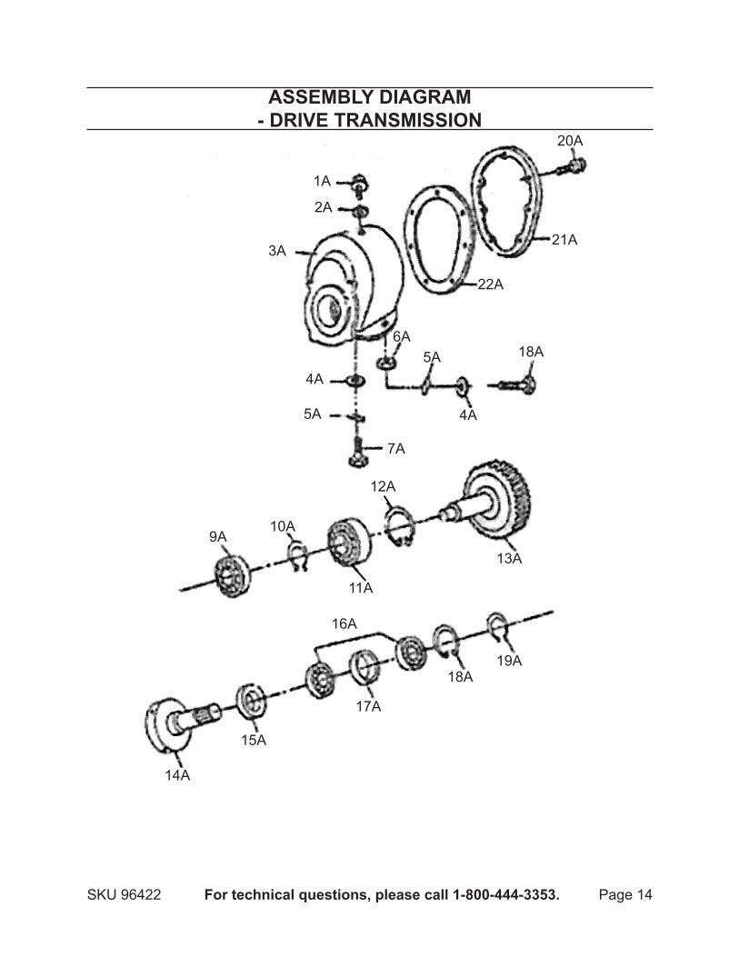
PARTS LIST - dRIvE TRANSMISSION
Part description Q’ty1A Hex Bolt (M14x1.5x15) 12A Washer (#14) 13A Transmission Housing 14A Flat Washer (#8) 65A Spring Washer (#8) 66A Nut (M8) 47A Hex Bolt (M8x30) 28A Hex Bolt (M8x40) 89A Bearing (6205) 1
10A Shaft Circlip (#35) 111A Bearing (6207) 1
Part description Q’ty12A Hole Circlip (#72) 113A Brace Gear 114A Driving Gear 115A Oil Seal (52x35x7) 116A Bearing (6205) 217A Shield Ring 118A Hole Circlip (#52) 119A Shaft Circlip (#25) 120A Hex Bolt (M6x20) 721A Back Cover 122A Seal Washer 1
Page 14SKU 96422 For technical questions, please call 1-800-444-3353.
ASSEMBLY dIAGRAM - dRIvE TRANSMISSION
14A
15A
16A
17A
18A19A
13A
12A
11A
10A9A
7A
5A
4A
18A
4A
5A6A
3A
2A
1A
20A
21A
22A

Page 15SKU 96422 For technical questions, please call 1-800-444-3353.
PARTS LIST - PISTON ASSEMBLY
Part description Q’ty1B Connection Rod 12B Bearing (6203) 13B Hole Circlip (#40) 14B Shaft Circlip (#17) 15B Whirl Rod 16B Flat Washer (#8) 17B Spring Washer (#8) 18B Self Locking Nut (M8) 19B Piston Rod 1
10B Combining Spring 111B Damp Spring 112B Hex Bolt (M8x20) 613B Spring Washer (#8) 6
Part description Q’ty14B Flat Washer (#8) 615B Oil Seal (2.65 x 10⁶) 116B Piston 117B Hoop 218B Protection Cover 119B Plate 120B Oil Seal (2.65x87.5) 121B Cylinder Cover Body 122B Washer (#8) 223B Hex Bolt (M8x12) 224B Oil Seal (2.65x10⁶) 125B Bottom Cover 126B Screw (M8x15) 3

Page 16SKU 96422 For technical questions, please call 1-800-444-3353.
ASSEMBLY dIAGRAM - PISTON ASSEMBLY1B
2B
3B
4B
5B6B
7B8B
9B
10B11B
12B
13B
14B
15B
16B
17B
18B
19B
20B
17B
21B
22B
23B24B
25B
26B

Page 17SKU 96422 For technical questions, please call 1-800-444-3353.
PARTS LIST - SUPPORT PLATE
Part description Q’ty1C Hook Strap 22C Pad 13C Bottom Plate 14C Nut (M12) 155C Spring Washer (Ø12) 15
Part description Q’ty6C Flat Washer (Ø12) 117C Bolt (M12x90) 28C Bolt (M12x120) 29C Bolt (M12x50) 11
10C Cushion Plate 1
1C
2C
10C
3C
4C
5C
7C
8C
9C
4C5C
6C

Page 18SKU 96422 For technical questions, please call 1-800-444-3353.
LIMITEd 90 dAY wARRANTYHarbor Freight Tools Co. makes every effort to assure that its products meet high
quality and durability standards, and warrants to the original purchaser that this product is free from defects in materials and workmanship for the period of 90 days from the date of purchase. This warranty does not apply to damage due directly or indirectly, to misuse, abuse, negligence or accidents, repairs or alterations outside our facilities, criminal activity, improper installation, normal wear and tear, or to lack of maintenance. We shall in no event be liable for death, injuries to persons or property, or for incidental, contingent, special or consequential damages arising from the use of our product. Some states do not allow the exclusion or limitation of incidental or consequential damages, so the above limitation of exclusion may not apply to you. THIS WARRANTY IS ExPRESSLY IN LIEU OF ALL OTHER WARRANTIES, ExPRESS OR IMPLIED, INCLUDING THE WARRANTIES OF MERCHANTABILITY AND FITNESS.
To take advantage of this warranty, the product or part must be returned to us with transportation charges prepaid. Proof of purchase date and an explanation of the complaint must accompany the merchandise. If our inspection verifies the defect, we will either repair or replace the product at our election or we may elect to refund the purchase price if we cannot readily and quickly provide you with a replacement. We will return repaired products at our expense, but if we determine there is no defect, or that the defect resulted from causes not within the scope of our warranty, then you must bear the cost of returning the product.
This warranty gives you specific legal rights and you may also have other rights which vary from state to state.
3491 Mission Oaks Blvd. • PO Box 6009 • Camarillo, CA 93011 • (800) 444-3353
Related Documents