UPPER BODY STRUCTURE DESIGN FOR SOLAR CAR MUHAMMAD SYAFIQ BIN AYOB Report submitted in partial fulfilment of the requirements for the award of the degree of Bachelor of Mechanical Engineering with Automotive Engineering Faculty of Mechanical Engineering UNIVERSITI MALAYSIA PAHANG DECEMBER 2010

Welcome message from author
This document is posted to help you gain knowledge. Please leave a comment to let me know what you think about it! Share it to your friends and learn new things together.
Transcript

UPPER BODY STRUCTURE DESIGN FOR SOLAR CAR
MUHAMMAD SYAFIQ BIN AYOB
Report submitted in partial fulfilment of the requirements for the award of the degree of
Bachelor of Mechanical Engineering with Automotive Engineering
Faculty of Mechanical Engineering UNIVERSITI MALAYSIA PAHANG
DECEMBER 2010

i
SUPERVISOR’S DECLARATION
I hereby declare that I have checked this project and in my opinion, this project is
adequate in terms of scope and quality for the award of the degree of Bachelor of
Mechanical Engineering with Automotive Engineering.
Signature
Name of Supervisor: MR ZAMRI MOHAMED
Position: LECTURER OF MECHANICAL ENGINEERING
Date: 6 DECEMBER 2010

ii
STUDENT’S DECLARATION
I hereby declare that the work in this project is my own except for quotations and
summaries which have been duly acknowledged. The project has not been accepted for
any degree and is not concurrently submitted for award of other degree.
Signature
Name: MUHAMMMAD SYAFIQ BIN AYOB
ID Number: MH07010
Date: 6 DECEMBER 2010

iv
ACKNOWLEDGEMENTS
I am grateful and would like to express my sincere gratitude to my supervisor Mr Zamri Mohamed for his germinal ideas, invaluable guidance, continuous encouragement and constant support in making this research possible. He has always impressed me with his outstanding professional conduct, his strong conviction for science, and his belief that a Degree program is only a start of a life-long learning experience.
I acknowledge my sincere indebtedness and gratitude to my parents for their love, dream and sacrifice throughout my life. I cannot find the appropriate words that could properly describe my appreciation for their devotion, support and faith in my ability to attain my goals. Special thanks should be given to my friends. I would like to acknowledge their comments and suggestions, which was crucial for the successful completion of this study.
v
ABSTRACT
This report presents on the design of upper body structure for solar car. Solar car uses solar energy from the sun to convert it into electrical energy in order to move the solar car. In order to move the solar car smoothly, the shape of solar car’s body must be more aerodynamics to get low drag and reduce the friction at the same time. The objective of this report is to propose several design of solar car’s body and analyze the models for drag coefficient and justify the most aerodynamics model. The report describes the aerodynamics concept use in common cars, computational fluid dynamics (CFD) analysis to calculate the drag coefficient and identify material and dimension of solar car. The dimension for the project is guided by World Solar Challenge regulations 2009 technical specifications. Fibreglass, kevlar and carbon fiber materials were studied in this report which is commonly used in nowadays solar car. The models of solar car were designed by using the computer-aided drawing software which is Solid Work. The CFD analysis was then performed using COSMOSFloWorks. Each model of solar car was analyzed using different mesh and speed of the air flow. Finally, the drag force of each model is obtained and used in the calculation to find coefficient of drag for each model. From the result, it is observed that frontal area and shape of the solar car’s body are the most important parameter to be considered in order to design an aerodynamics car. Besides designing the aerodynamics shape of solar car, the choice of material for body can also affect the performance of the vehicle because different material will contribute the weight of the vehicle. As the vehicle is lighter, it will improve the vehicle power to weight ratio. Thus, improve the performance of the vehicle.

vi
ABSTRAK
Laporan ini membentangkan tentang reka bentuk struktur tubuh bahagian atas kereta solar. Kereta solar menggunakan tenaga suria daripada matahari dan mengubahkannya menjadi tenaga elektrik untuk menggerakkan kereta solar. Untuk menggerakkan kereta solar dengan lancar, bentuk kereta solar hendaklah aerodinamik untuk mengurangkan daya rintangan dan geseran pada masa yang sama. Objektif laporan ini adalah mencadangkan dan mereka bentuk beberapa tubuh kereta solar dan menganalisis model kereta itu untuk mencari pekali geseran dan mengenalpasti model yang paling aerodinamik. Laporan ini menghuraikan mengenai konsep aerodinamik yang digunakan pada kebanyakan kereta, analisis perisian computational fluid dynamics (CFD) untuk mengira pekali geseran dan mengenalpasti bahan dan dimensi kereta solar. Dimensi kereta solar untuk projek ini adalah berdasarkan spesifikasi teknikal mengikut peraturan World Solar Challenge 2009. Bahan fiberglass, kevlar dan serat karbon adalah bahan yang digunakan untuk menghasilkan kereta solar dikaji dalam laporan ini. Model-model kereta solar telah direka bentuk menggunakan perisisan Solid Work. Analisis CFD dijalankan menggunakan perisian COSMOSFloWorks. Setiap model kereta solar dianalisiskan menggunakan mesh dan halaju aliran udara yang berbeza. Akhir sekali, daya rintangan diperoleh daripada analisis dan digunakan dalam pengiraan untuk mencari pekali geseran untuk setiap model. Daripada keputusan yang diperoleh, luas permukaan hadapan dan bentuk tubuh kereta solar dikenalpasti sebagai antara parameter yang penting untuk mereka bentuk kereta solar yang aerodinamik. Selain bentuk kereta solar yang aerodinamik, pemilihan bahan untuk rangka kereta solar boleh mempengaruhi prestasi kenderaan kerana setiap bahan boleh mempengaruhi berat kenderaan. Kereta yang lebih ringan akan meningkatkan berat nisbah kuasa kenderaan. Oleh itu, prestasi kereta akan meningkat.

vii
TABLE OF CONTENTS
Page
SUPERVISOR’S DECLARATION i
STUDENT’S DECLARATION ii
ACKNOWLEDGEMENTS iv
ABSTRACT v
ABSTRAK vi
TABLE OF CONTENTS vii
LIST OF TABLES xi
LIST OF FIGURES xi
LIST OF SYMBOLS xiii
CHAPTER 1 INTRODUCTION
1.1 Project Background 1
1.3 Problem Statement 3
1.3 Objectives of the Project 4
1.4 Project Scope 4
CHAPTER 2 LITERATURE REVIEW
2.1 Introduction 5
2.2 History Of Solar Car 5
2.3 Definition Of Solar Car 7
2.4 Design Concept 8
2.4.1 Aerodynamics 8 2.4.2 Air flow between underside and ground 10 2.4.3 Internal Airflow 11 2.4.4 Styling Streamlined Back 11 2.4.5 Covers Over The Rear Wheels 12 2.4.6 Aerodynamics Lift 13 2.4.7 Reducing Lift By Styling 13 2.4.8 Spoiler And Negatives Lift Devices 14 2.4.9 Important Issues About Aerodynamics 14

viii
2.5 Aerodynamic Design Aspects Of A Solar Powered Car 15
2.6 World Solar Challenge Regulations 2009 Technical Specifications 18
2.6.1 Size 18 2.6.2 Seats 19 2.6.3 Doors and openings 19
2.7 Body Material 20
2.7.1 Fiberglass 20 2.7.2 Carbon Fiber 21 2.7.3 Kevlar 21
2.8 Computational Fluid Dynamics (CFD) 23
2.8.1 Advantages of CFD 23 2.8.2 Applications of CFD 24 2.8.3 COSMOSFloWorks Software 26
CHAPTER 3 METHODOLOGY
3.1 Introduction 28
3.2 Flow Chart 29
3.3 Bechmark Models 31
3.3.1 Aurora 101 Solar Car 31 3.3.2 Tokai Challenger Solar Car 33 3.3.3 Nuna 5 Solar Car 35
3.4 Dimension of Project 37
3.5 Material Selection 37
3.6 Modeling Design 37
3.6.1 Sketching 38 3.6.2 CAD Modeling 39
3.7 CFD Analysis 42
3.7.1 Sensitivity Analysis 42
CHAPTER 4 RESULTS AND DISCUSSION
4.1 Introduction 44
4.2 Simulation Result and analysis 44
4.2.1 Model 1 45 4.2.2 Model 2 51 4.2.3 Model 3 57

ix
4.2.4 Model 4 63 4.2.5 Model 5 69
4.3 Grid Sensitivity Analysis 75
4.4 Model Selection 76
4.5 Material Selection 76
CHAPTER 5 CONCLUSION AND RECOMMENDATIONS
5.1 Conclusions 79
5.2 Recommendations 80
REFERENCES 81
APPENDICES
A1 Gantt Chart of FYP 1 82
A2 Gantt Chart of FYP 2 83
B1 Technical Drawing of Model 1 84
B2 Technical Drawing of Model 2 85
B3 Technical Drawing of Model 3 86
B4 Technical Drawing of Model 4 87
B5 Technical Drawing of Model 5 88
x
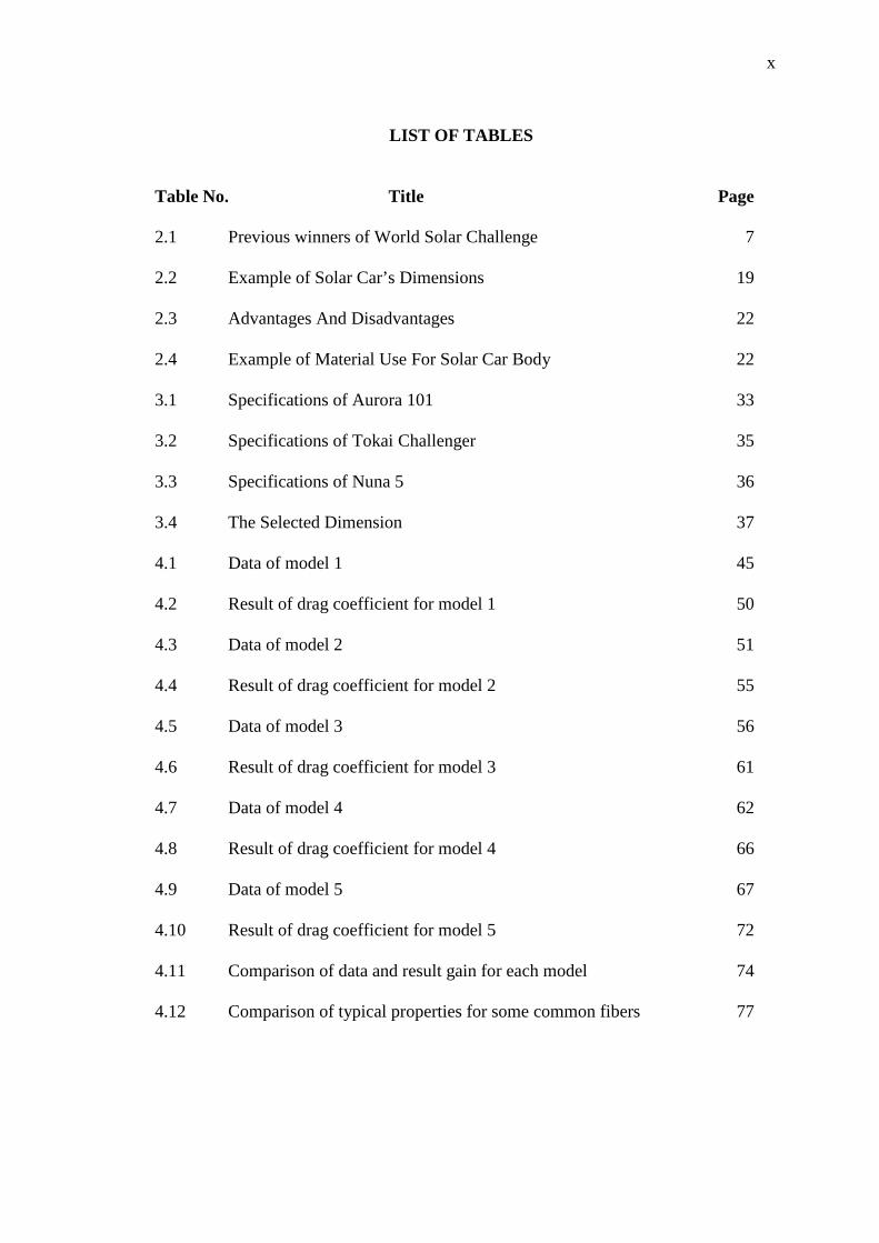
LIST OF TABLES
Table No. Title Page 2.1 Previous winners of World Solar Challenge 7 2.2 Example of Solar Car’s Dimensions 19 2.3 Advantages And Disadvantages 22 2.4 Example of Material Use For Solar Car Body 22 3.1 Specifications of Aurora 101 33 3.2 Specifications of Tokai Challenger 35 3.3 Specifications of Nuna 5 36 3.4 The Selected Dimension 37 4.1 Data of model 1 45 4.2 Result of drag coefficient for model 1 50 4.3 Data of model 2 51 4.4 Result of drag coefficient for model 2 55 4.5 Data of model 3 56 4.6 Result of drag coefficient for model 3 61 4.7 Data of model 4 62 4.8 Result of drag coefficient for model 4 66
4.9 Data of model 5 67 4.10 Result of drag coefficient for model 5 72 4.11 Comparison of data and result gain for each model
74
4.12 Comparison of typical properties for some common fibers 77

xi
LIST OF FIGURES
Figure No. Title Page 2.1 Body shape 9 2.2 Morelli’s streamlined car 10 2.3 Drawing of the new airliner car 12 2.4 Honda Insight with covered rare wheels 13 2.5 Spoiler 14 2.6 The Forces Acting On A Moving Car 16 2.7 Graph Power Require vs Speed 18 2.8 Pressure field of a helicopter 24 2.9 Temperature distribution of a mixing manifold 25 2.10 Pressure contours of a blood pump 25 3.1 Flow chart of the project methodology 30 3.2 Isometric view of Aurora 101 32 3.3 Side view of Aurora 101 35 3.4 Isometric view of Tokai Challenger 34 3.5 Side view of Tokai Challenger 34 3.6 Isometric view of Nuna 5 35 3.7 Side view of Nuna 5 36 3.8 Rough Sketching 38 3.9 CAD model of model 1 39 3.10 CAD model of model 2 40 3.11 CAD model of model 3 40 3.12 CAD model of model 4 41

xii
3.13 CAD model of model 5 42 3.14 CFD graphic user interface 42
3.15 One level of initial mesh 43 3.16 Two level of initial mesh 44 3.17 Three level of initial mesh 44
3.18 Four level of initial mesh 44
3.19 Five level of initial mesh 44 4.1 Velocity flow of model 1 46 4.2 Graft of drag force for model 1 47 4.3 Graft of coefficient of drag for model 1 50 4.4 Velocity flow of model 2 52 4.5 Graft of drag force for model 2 52 4.6 Graft of coefficient of drag for model 2 56 4.7 Velocity flow of model 3 57 4.8 Graft of drag force for model 3 58 4.9 Graft of coefficient of drag for model 3 61 4.10 Velocity flow of model 4 63 4.11 Graft of drag force for model 4 63 4.12 Graft of coefficient of drag for model 4 67 4.13 Velocity flow of model 5 68 4.14 Graft of drag force for model 5 69 4.15 Graft of coefficient of drag for model 5 72 4.16 Technical drawing of finalize model 75

xiii
LIST OF SYMBOLS
Cd Drag coefficient A Frontal area
� Density v Speed of the object relative to the air Fr
Rolling resistance

CHAPTER 1
INTRODUCTION
1.1 PROJECT BACKGROUND
Solar technology is not new in nowadays world. Its history spans from the 7th
Century B.C. until today. In 7th Century B.C., magnifying glass used to concentrate sun
array to make fire and to burn ants. In 3rd Century B.C., Greek and Romans use burning
mirrors to light torches for religious purposes. In 2nd Century B.C., the Greek scientist,
Archimedes, used the reflective properties of bronze shields to focus sunlight and to set
fire to wooden ships from the Roman Empire which were besieging Syracuse. Although
there is no such feat proof exist, the Greek navy recreated the experiment in 1973 and
successfully set fire to wooden boat at a distance of 50 meters (Hoyer, 2008). Today,
there are a lot application uses solar technologies from solar powered buildings to solar
powered vehicles.
Solar technology has developed from a century to another century. In 20th
century, Wilhelm Hallwachs discovered that a combination of copper and cuprous oxide
is photosensitive. Albert Einstein published his paper on the photoelectric effect and
wins the Nobel Prize for his theory explaining the photoelectric effect in 1921. In 1954,
photovoltaic technology was born in the United State when Daryl Chapin, Calvin Fuller
and Gerald Pearson develop the silicon photovoltaic (PV) cell at Bell labs where it is the
first solar cell capable of converting enough of the sun’s energy into power to run
everyday electrical equipment (Smestad, 2007).

2
In 21st century, the First Solar begins production in Perrysburg, Ohio, at the
world’s largest photovoltaic manufacturing plant with an estimated capacity of
producing enough solar panels each year to generate 100 megawatts of power. At the
International Space Station, Astronauts began installing solar panels on what will be the
largest solar power array deployed in space. The National Space Development Agency
of Japan (NASDA) announces plans to develop a satellite based solar power system that
would beam energy back to earth (Hardy, 2009).
Solar cars combine technology typically used in the alternative energy and
automotive industries. The solar car owes its existence to photovoltaic cell, a tiny piece
of silicon which transfers the power of the sun to the batteries. The photovoltaic cell
made its appearance in the United States in 1954. Solar cars depend on PV cells to
convert sunlight into electricity. Approximately, 51% of sunlight enters the Earth’s
atmosphere. When sunlight or photons strike PV cells, they excite electrons and allow
them to flow, creating an electrical current (Smestad, 2007).
In the early years of automobiles, the races were use as the laboratories where car
development often took place. In 1983, Hans Tholstrup and Larry Perkins opened up
solar car racing when they went on an epic Solar Trek from Perth to Sydney in Australia.
This vehicle was the world's first solar powered car. And its name fit the exploit 'Quiet
Achiever'. After that, the solar car races started crude and helped to propagate solar
energy as an alternative. The success of his first venture across the Australian outback
led Hans Tholstrup to start the World Solar Challenge in 1987. There are 23 participants
inaugurated the Australian World Solar Challenge. The leapfrog over the first effort
showed in 1987 when GM's Sunraycer won the event with an average speed of 67
km/hour. Today, the event is a biannual jamboree and also a barometer for the
developments in the field of solar cars. For instance, 2005 witnessed cars touching
speeds in excess of 100 km/hour. This lead to some major regulation changes
concerning safety (West, 1999).

3
The World Solar Challenge started it and soon others followed the lead. The
North American Solar Challenge brings numerous of University teams putting their idea,
creativity and brains as well as their skills against each other. The challenge started from
Dallas, Texas to Calgary, Alberta. General Motors had followed up its success in the
World Solar Challenge by starting this American/Canadian version. It was an
inspirational effort in order to promote auto engineering and solar energy among
students (Hoyer, 2008). It may not intruded into the popular races of Formula One but
with the races around the world such as Suzuki Circuit (Japan), World Solar Rally
(Taiwan) and others.
Nowadays, the solar car has become the popular mechanics. Practical on road
applications are looking to use solar energy in hybrid configurations. The France’s
Venturi AstroLab is being known as the world’s first electro solar hybrid car where it
has a top speed of 120 km/hour and a continuous run of 110 km. There are solar taxis or
Solartx in Swiss vision where the car attempts to be a trendsetter for a dependable
everyday automobile. It is powered by a 6 m2 area of solar array and it can go about 400
km without recharging. It also includes a trailer and its maximum speed hovers around
90 km/hour. Big company like Toyota is looking to add solar panels on its Prius.
Innovatively, the optional attachments can deliver 300 watts of energy and also act as
sunshades (Hoyer, 2008).
1.2 PROBLEM STATEMENT
Aerodynamics is a branch of dynamics concerned with studying the motion of
air, particularly when it interacts with a moving object such as solar cars. When drag is
high, the drag force will increase. Thus a lot of energy will use to overcome it. To
reduce amount of energy use when moving, the solar car must be more aerodynamics as
it can affect drag and friction. In order to overcome it, most solar car have been designed
more aerodynamics and streamline to get low drag.

4
1.3 PROJECT OBJECTIVE
There are two main objectives to achieve in this research. Firstly, the objective is
to design solar car’s body in order to get low the drag. Secondly, the objective is to
analyze drag coefficient of the models and justify the most aerodynamics model.
1.4 PROJECT SCOPE
In order to achieve the objectives, there are two scopes of project. Firstly, sketch
and design several solar car models according to aerodynamics concept by using Solid
Work engineering tool. Secondly, analyze the drag coefficient (Cd) of the model by
using COSMOSFloWorks software.

CHAPTER 2
LITERATURE REVIEW
2.1 INTRODUCTION
The design of solar car upper body is one of the important part in developing a
complete solar car. The upper body is the part where solar panel is being mounted and
gains power by transfer the sun light energy into electric energy. In designing a solar car,
as in any project, firstly is to identify the purpose of the car. For example the purpose is
to be race in the biennial American Solar Challenge. This specific goal will shape the
design priorities of the car and will impose in the form of the race regulation. The
regulation provides maximum dimensions, safety requirement and performance
requirements.
The most important part in understanding the design problem is how to design
the solar more aerodynamics in order to reduce the drag. The design of solar car is
connected with aerodynamics drag. When the aerodynamics drag is reduced, it will
improve fuel economy and higher top speed.
2.2 HISTORY OF SOLAR RACING
In the early years of automobiles, the races were used as the laboratories where
car development often took place. In 1983, Hans Tholstrup and Larry Perkins opened up
solar car racing when they went on an epic Solar Trek from Perth to Sydney in Australia.
The vehicle practically resembled a 16 foot open boat. But it did 4052 km in 20 days, at
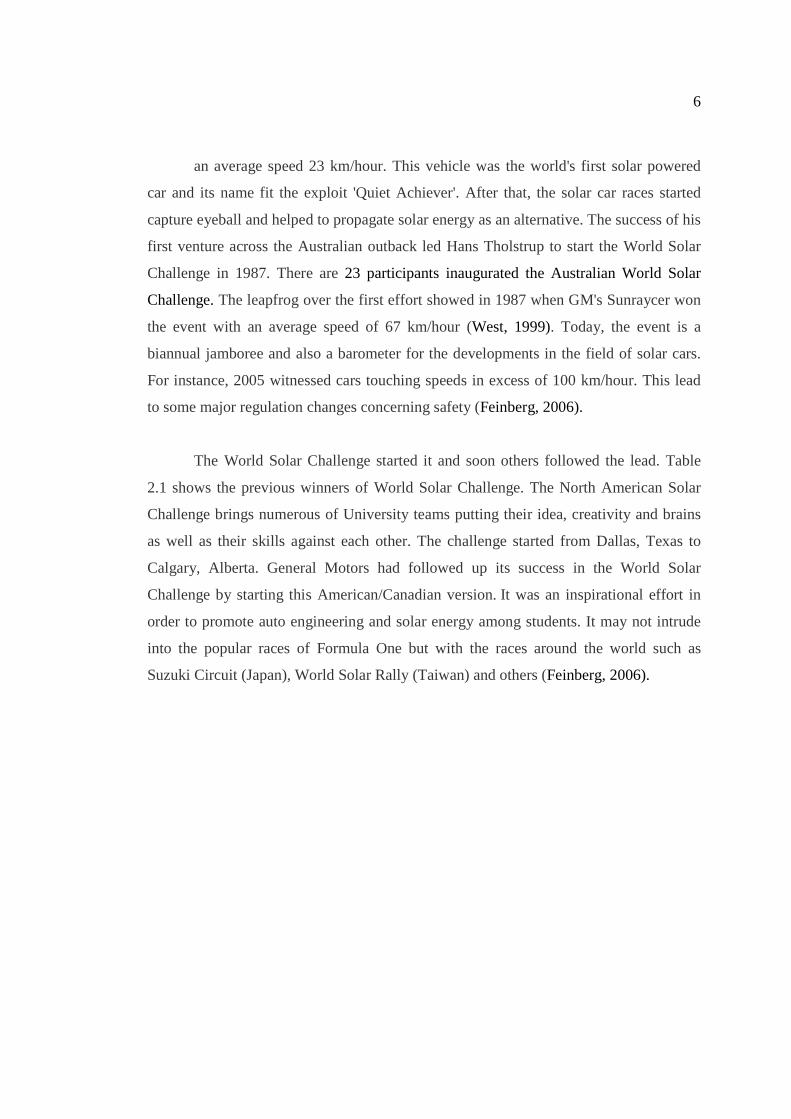
6
an average speed 23 km/hour. This vehicle was the world's first solar powered
car and its name fit the exploit 'Quiet Achiever'. After that, the solar car races started
capture eyeball and helped to propagate solar energy as an alternative. The success of his
first venture across the Australian outback led Hans Tholstrup to start the World Solar
Challenge in 1987. There are 23 participants inaugurated the Australian World Solar
Challenge. The leapfrog over the first effort showed in 1987 when GM's Sunraycer won
the event with an average speed of 67 km/hour (West, 1999). Today, the event is a
biannual jamboree and also a barometer for the developments in the field of solar cars.
For instance, 2005 witnessed cars touching speeds in excess of 100 km/hour. This lead
to some major regulation changes concerning safety (Feinberg, 2006).
The World Solar Challenge started it and soon others followed the lead. Table
2.1 shows the previous winners of World Solar Challenge. The North American Solar
Challenge brings numerous of University teams putting their idea, creativity and brains
as well as their skills against each other. The challenge started from Dallas, Texas to
Calgary, Alberta. General Motors had followed up its success in the World Solar
Challenge by starting this American/Canadian version. It was an inspirational effort in
order to promote auto engineering and solar energy among students. It may not intrude
into the popular races of Formula One but with the races around the world such as
Suzuki Circuit (Japan), World Solar Rally (Taiwan) and others (Feinberg, 2006).

7
Table 2.1 : Previous winners of World Solar Challenge
Place Winners
2003 Event
1st Place 2nd Place
Nuon "Nuna II" (NL) average speed 97.02 Km/h Aurora "Aurora 101" (AUS) average speed 91.90 Km/h
2005 Event
1st Place 2nd Place 3rd Place
Nuon "Nuna III" (NL) average speed 102.75 Km/h Aurora "Aurora 101" (AUS) average speed 92.03 Km/h University of Michigan "Momentum" (USA) average speed 90.03 Km/h
2007 Event
1st Place 2nd Place 3rd Place
Nuon "Nuna 4" (NL) average speed 90.87 Km/h Umicore "Umicar Infinity" (Belgium) average speed 88.05 Km/h Aurora "Aurora 101" (Australia) average speed 85 Km/h
Source : http://www.globalgreenchallenge.com.au/wsc-evolution/previous-winners
2.3 DEFINITION OF SOLAR CAR
A solar car is an electric vehicle powered by solar energy obtained from solar
panels on the car. Actually solar car is not a form of transportation yet because they can
only be operation during the day and can carry one or two passenger only. Solar cars
rely on Photovoltaic (PV) cells to convert sun energy into electricity which according to
the fact, 51% of sunlight actually enters the Earth's atmosphere. When the sunlight
strikes PV cells, they will activate electrons and allow them to flow by creating an
electrical current (Kalm, 2007). Nowadays, there are a lot of competition around the
worlds such as the American Solar Challenge, South African Solar Challenge and World
Solar Challenge. These events are usually sponsored by government agencies such as the
United State Department of Energy in order to promote the development of alternative
energy technology such as solar cell. Besides, it is also to promote the use of clean and
sustainable energy. As we know the energy we use now such as petrol is depleting. The

8
competitions are often participated by the universities to develop their students
engineering and technology (Dawson, 2007).
2.4 DESIGN CONCEPT
2.4.1 Aerodynamics
Low aerodynamic drag on land vehicles has been developed almost as long as
automobiles have graced our roads. Reducing aerodynamics drag is important for
improved fuel economy and higher top speeds, for a given power. There are usually two
ways to approach aerodynamics drag reduction for land vehicles (Kalm, 2007).
(i) The ground-up approach, where the main body is shaped for low drag and
then non-aerodynamics elements are designed within the body constraints
(ii) The improvement approach, where the designer starts with a vehicle that
already satisfies the non-aerodynamics constraints and finesses the details to
lower the drag as much as practical.
Figure 2.1 shows two body shapes where to prevent the drag in body shape (a)
increase, the body can be cambered just like in body shape (b).

9
Figure 2.1: Body shape
Source : Elle Kalm (2007)
The first known streamlined land vehicle was developed by Jaray and Klemperer
in 1920. They have discovered that, though an axisymmetric teardrop body has the
lowest drag in free air, when that body is brought close to the ground, the drag increases
dramatically. For example, in the ground clearances found in automobiles, the drag of
torpedo shape can increase 50%. If the ground clearance nears zero, the drag of a
torpedo shape car increase as much as 500%. To preserve the robustness, Jaray and
Klemperer invented the solution by cambering the body. To camber the body, the belly
can be flattened or the topside of the body can be arched higher as in figure above
(Kalm, 2007).
Around 1980s, a professor of the Turin Technical University (Italy), Professor A.
Morelli investigated whether it was possible for basic body, near the ground, to have a
drag equivalent to streamlined body in free air. The Morelli body achieved a minimum
drag coefficeint, based on frontal area of under 0.05, matching that streamlined bodies in
free air (Kalm, 2007).

10
Figure 2.2 : Morelli’s streamlined car
Source : Elle Kalm (2007)
Aerodynamic problems can be classified in external and internal aerodynamics.
External aerodynamics is the study of flow around solid object of various shapes.
Evaluating the lift and drag on an airplane, the shock wave that form in front of the nose
of a rocket or the flow of air over a hard drivehead are examples of external
aerodynamics. Internal aerodynamics is the study of flow through passages in solid
objects. For instance, internal aerodynamics encompasses the study of the airflow
through a jet engine or through an air conditioning pipe. (Kalm, 2007)
2.4.2 Air flow between underside and ground
The motion of the car on the ground introduces problem which differ greatly
from those of an aircraft, primarily because of interference with air flow between the car
underside and the ground. That is because the car moves very closely to the ground this
interference is one of the most important features of the air flow pattern around it
(Genese, 2006). Biggest problem with many cars on the road today is that most of them
have very rough undersides due of course to the presence of exhausts pipe and silencers,

11
overhung petrol tanks, wheel axels, differentials, suspensions, shock absorbers, brake
cables and wheel cavities. The average roughness is approximately 15 cm considered
from a main surface level. Airflow between the underside and the ground is therefore
affected by (Kalm, 2007),
(i) The distance between the undersides and the ground
(ii) The width, length and height ratio of the vehicle and the styling of the body
shape
(iii)The roughness of the underside
(iv) The lengthwise are crosswise curvature of the underside panel
2.4.3 Internal Airflow
The internal airflow is the problem which analyses of car aerodynamics cannot
avoid. In fact the car engine and sometimes the brakes, requires a quite considerable
mass of air to be drawn through the inside of the car. This mass of air is taken from the
outside flow and induced to pass through a system of internal ducts and cavities. A fan
operating within the internal duct is either assisted this airflow or it utilizes the external
pressure differences between the inlet and the outlet of the internal duct. The internal
airflow has a two-fold effect on the external airflow pattern (Kalm, 2007).
2.4.4 Styling Streamlined Back
In order to reduce the intensity of turbulence through discussing the general
airflow pattern over the car, the size of the wake behind the car is called ‘bobtailing’.
Therefore, it is better to style the rear surface because it can slopes gently backwards to
avoid premature flow separation. The separation would be inevitable at a line due to
viscous friction the shape is cut or ‘bobtailed’ (Kalm, 2007) in Figure 2.3.
Related Documents